

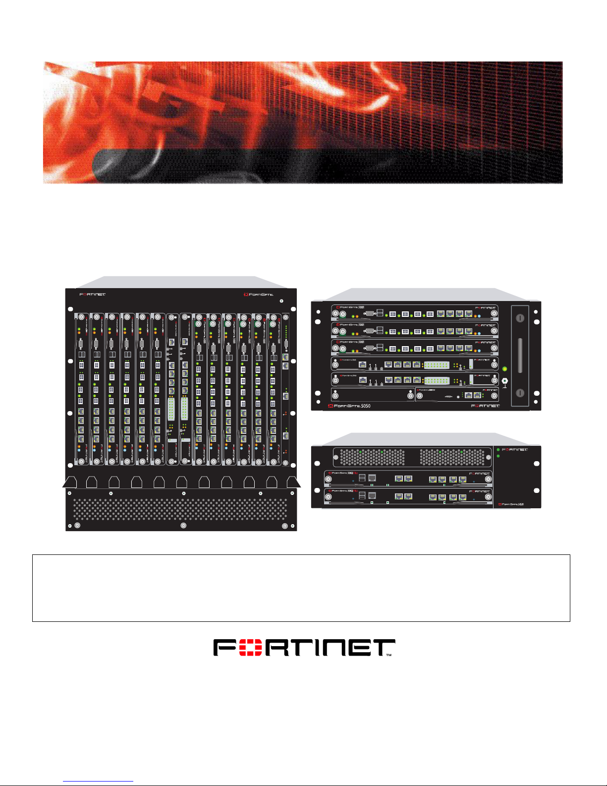
Fortinet FortiGate-5001SX, FortiGate-5001A, FortiGate-5020, FortiGate-5002FB2, FortiGate-5001FA2 Hardware Manual
...
5
5
HARDWARE GUIDE
13 11 9 7 5 3 1 2 4 6 8 10 12 14
PWR
PWR
PWR
PWR
PWR
PWR
ACC
ACC
CONSOLE
USB
1 2
3 4
5 6 7 8
STA IPM
STA IPM
ACC
ACC
CONSOLE
CONSOLE
USB
USB
1 2
1 2
3 4
3 4
5 6 7 8
5 6 7 8
STA IPM
STA IPM
ACC
ACC
CONSOLE
CONSOLE
USB
USB
1 2
1 2
3 4
3 4
5 6 7 8
5 6 7 8
STA IPM
MANAGEMENT
MANAGEMENT
CONSOLE
E
E
T
T
H
H
O
O
USB
SYSTEM
SYSTEM
CONSOLE
CONSOLE
R
R
S
S
1 2
2
2
3
3
2
2
Z
Z
R
R
E
E
0
0
Z
Z
R
R
E
E
1
1
3 4
Z
Z
R
R
E
E
2
2
E2
E1
E2
E1
1514
1514
1312
1312
1110
1110
98
98
76
76
5 6 7 8
54
54
32
32
10
10
ZRE
ZRE
OKCLK
OKCLK
INTEXT
INTEXT
FLT
FLT
FLT
FLT
HOT SWAP
HOT SWAP
RESET
RESET
LED MODE
LED MODE
STA IPM
PWRACC
PWRACC
PWRACC
CONSOLE
CONSOLE
USB
USB
1 2 3 4 5 6 7 8
1 2 3 4 5 6 7 8
STA IPM
STA IPM
STA IPM
PWRACC
PWRACC
CONSOLE
1 2 3 4 5 6 7 8
CONSOLE
CONSOLE
USB
USB
USB
1 2 3 4 5 6 7 8
1 2 3 4 5 6 7 8
STA IPM
STA IPM
FortiGate-5000 Series
5140
USB
1 2 3 4 5 6 7 8
CONSOLE
PWRACC
5
Crit.
Maj.
Min.
PWRACC
3
2
1
CONSOLE
Alarms
Rst
USB
1 2 3 4 5 6 7 8
4
3
2
1
Link
Act
100
ETH 0
Prim.
ShMC
Stat.
Link
Act
100
ETH 0
STA IPM
Sec.
ShMC
Stat.
ShMC
2
USB
1 2 3 4 5 6 7 8
CONSOLE
PWRACC
USB
1 2 3 4 5 6 7 8
CONSOLE
PWRACC
ETH
O
RS232ZRE0ZRE1ZRE2
SYSTEM
CONSOLE
MANAGEMENT
ETH
O
RS232ZRE0ZRE1ZRE2
SYSTEM
CONSOLE
MANAGEMENT
USB
CONSOLE
RESET
STATUS
PWR
USB
CONSOLE
RESET
STATUS
PWR
162
162
E1
9876543210
1514
1312
1110
E2
E1
9876543210
1514
1312
1110
E2
3 4 5 6
3 4 5 6
STA IPM
STA IPM
STA IPM
OKCLK
INTEXT
FLT
HOT SWAP
RESET
ZRE
FLT
OKCLK
INTEXT
FLT
HOT SWAP
RESET
ZRE
FLT
Critical
Major
Minor
Alarm
Alarm
Console Ethernet
Reset
ON/OFF
IPM
ON/OFF
IPM
POWER
LED MODE
LED MODE
ShMC
Hot Swap
Status
1
PSUA
PSU B
ALT
ALT
A detailed guide to all three F ortiGate-5000 series cha ssis and the FortiGate and FortiSwitch modules that you can install
in them. This document describes each chassis and all its components and provides information about how to connect
power to each chassis. For each FortiGate and FortiSwitch module, this document describes the module LEDs and
connectors, describes how to install each module in a FortiGate-5000 series chassis, and contains a brief
troubleshooting section to help you diagnose and fix problems with the module.
www.fortinet.com

FortiGate-5000 Series Hardware Guide
!
15 March 2006
01-00000-0293-20060315
© Copyright 2006 Fortinet, Inc. All rights reserved. No part of this
publication including text, examples, diagrams or illustrations may be
reproduced, transmitted, or translated in any form or by any means,
electronic, mechanical, manual, optical or otherwise, for any purpose,
without prior written permission of Fortinet, Inc.
Trademarks
Dynamic Threat Prevention System (DTPS), APSecure, FortiASIC,
FortiBIOS, FortiBridge, FortiClient, FortiGate, FortiGate Unified Threat
Management System, FortiGuard, FortiGuard-Antispam, FortiGuardAntivirus, FortiGuard-Intrusion, FortiGuard-Web, FortiLog, FortiAnalyzer,
FortiManager, Fortinet, FortiOS, FortiPartner, FortiProtect, FortiReporter,
FortiResponse, FortiShield, FortiVoIP, and FortiWiFi are trademarks of
Fortinet, Inc. in the United States and/or other countries. The names of
actual companies and products mentione d herein may be the trade marks
of their respective owners.
Regulatory compliance
FCC Class A Part 15 CSA/CUS
Note: If you install a battery that is not the correct type, it could explode.
Dispose of used batteries according to local regulations.
Version Date Description of changes
1 Feb 14, 2006 First release
2 March 15,
2006
• Corrected gigabit ethernet interface
specification (changed 1000Base-TX to
1000Base-T).
• Adjusted some page formatting.

Contents
Contents
Introduction........................................................................................ 7
About the FortiGate-5000 series chassis........................................................ 7
FortiGate-5140 chassis................................................................................. 7
FortiGate-5050 chassis................................................................................. 7
FortiGate-5020 chassis................................................................................. 8
About the FortiGate-5000 series modules....................................................... 8
FortiGate-5001SX module .. ... ... .... ... ... ... ....................................................... 8
FortiGate-5001FA2 module........................................................................... 8
FortiGate-5002FB2 module........................................................................... 8
FortiSwitch-5003 module .............................................................................. 8
Warnings and cautions..................................................................................... 9
About Data Center DC power ........................................................................... 9
Fortinet documentation................................................................................... 10
Fortinet Knowledge Center ......................................................................... 10
Comments on Fortinet technical documentation......................................... 10
Customer service and technical support...................................................... 10
FortiGate-5140 chassis.................................................................... 11
FortiGate-5140 chassis front panel................................................................ 12
FortiGate-5140 chassis back panel................................................................ 13
Physical description of the FortiGate-5140 chassis..................................... 14
Mounting the FortiGate-5140 chassis............................................................ 14
Air flow ......... .... ... ... ... ... ............................................................................... 14
Connecting a FortiGate-5140 chassis to Data Center DC power and Data
Center ground.................................................................................................. 15
Connecting FortiGate-5140 power zones ................................................... 15
Connecting a FortiGate-5140 PEM to Data Center DC power.................... 16
Connecting the FortiGate-5140 chassis to Data Center ground ................. 17
Connecting the FortiGate-5140 chassis to AC power using the
FortiGate-5053 power converter tray............................................................. 18
FortiGate-5053 power converter tray front and back panel......................... 18
Selecting the power supplies and power convertor trays that
you need for your FortiGate-5140 configuration ........ ... ... ... .... ... ... ... ... .... ... . 19
Connecting a FortiGate-5140 chassis to the FortiGate-5053 power
converter tray ................................... ... ... .... ... ... ... ... .... ................................. 23
Inserting FortiGate-5000 and FortiSwitch-5000 module s into a FortiGate-5140
chassis.............................................................................................................. 25
FortiGate-5000 Series Hardware Guide
01-00000-0293-20060315 3

Contents
FortiGate-5050 chassis.................................................................... 27
FortiGate-5050 front panel.............................................................................. 27
FortiGate-5050 back panel.............................................................................. 28
Physical description of the FortiGate-5050 chassis .................................... 29
Mounting the FortiGate-5050 chassis............................................................ 29
Air flow ........................................................................................................ 30
Connecting the FortiGate-5050 chassis to Data Center DC power
and Data Center ground.................................................................................. 30
Connecting the FortiGate-5050 chassis to AC power using the
FortiGate-5053 power converter tray............................................................. 32
FortiGate-5053 power converter tray front and back panel ........................ 32
Selecting the power supplies and power convertor trays that you
need for your FortiGate-5050 configuration......... ... ... ... .... ... ... ... ... .... ... ... ... . 33
Connecting a FortiGate-5050 chassis to the FortiGate-5053
power converter tray ................................................................................... 37
Inserting FortiGate-5000 and FortiSwitch-5000 modules into a
FortiGate-5050 chassis................................................................................... 38
FortiGate-5020 chassis.................................................................... 41
FortiGate-5020 front panel.............................................................................. 41
FortiGate-5020 back panel.............................................................................. 42
Physical description of the FortiGate-5020 chassis .................................... 43
Mounting the FortiGate-5020 chassis............................................................ 43
Air flow ........................................................................................................ 43
Connecting the FortiGate-5020 chassis to AC power.................................. 43
Inserting FortiGate-5000 modules into a FortiGate-5020 chassis .............. 44
FortiGate-5001SX security system................................................. 45
Front panel LEDs and connectors................................................................. 46
LEDs........................................................................................................... 46
Connectors.................................................................................................. 47
SFP transceiver options....................................... ... ... ... .... ... ... ... ... .............. 47
Installing the RAM DIMMs............................................................................... 47
Installing SFP transceivers............................................................................. 49
Changing jumper settings.............................................................................. 49
Inserting a FortiGate-5001SX module into a chassis................................... 51
Before inserting the FortiGate-5001SX module in a chassis ...................... 52
Insertion procedure.... ... ... ... .... ... ............................................................. ... . 52
Removing a FortiGate-5001SX module from a chassis............................... 55
FortiGate-5000 Series Hardware Guide
4 01-00000-0293-20060315

Contents
Troubleshooting .............................................................................................. 56
FortiGate-5001SX does not startup ............................................................ 57
FortiGate-5001SX cannot display chassis information ............................... 58
FortiGate-5001FA2 security system............................................... 59
Front panel LEDs and connectors................................................................. 60
LEDs ........................................................................................................... 60
Connectors.................................................................................................. 61
SFP transceiver options.............................................................................. 61
Installing the RAM DIMMs............................................................................... 61
Installing SFP transceivers............................................................................. 63
Changing jumper settings .............................................................................. 63
Inserting a FortiGate-5001FA2 module into a chassis................................. 65
Before inserting the FortiGate-5001FA2 module in a chassis..................... 66
Insertion procedure ..................................................................................... 66
Removing a FortiGate-5001FA2 module from a chassis ............................. 69
Troubleshooting .............................................................................................. 70
FortiGate-5001FA2 does not startup........................................................... 70
FortiGate-5001FA2 cannot display chassis information.............................. 72
FortiGate-5002FB2 security system............................................... 73
Front panel LEDs and connectors................................................................. 73
LEDs ........................................................................................................... 74
Connectors.................................................................................................. 74
Installing the RAM DIMMs............................................................................... 75
Inserting a FortiGate-5002FB2 module into a chassis................................. 77
Before inserting the FortiGate-5002FB2 module in a chassis..................... 77
Insertion procedure ..................................................................................... 77
Removing a FortiGate-5002FB2 module from a chassis ............................. 80
Troubleshooting .............................................................................................. 82
FortiGate-5002FB2 does not startup........................................................... 83
FortiSwitch-5003 module................................................................. 85
Front panel LEDs and connectors................................................................. 86
LEDs ........................................................................................................... 86
Connectors.................................................................................................. 87
Inserting a FortiSwitch-5003 module into a chassis .................................... 87
Removing a FortiSwitch-5003 module from a chassis................................. 90
Troubleshooting .............................................................................................. 92
FortiSwitch-5003 does not startup .............................................................. 92
Index.................................................................................................. 93
FortiGate-5000 Series Hardware Guide
01-00000-0293-20060315 5

Contents
FortiGate-5000 Series Hardware Guide
6 01-00000-0293-20060315

Introduction About the FortiGate-5000 series chassis
Introduction
This document describes the features of each FortiGate-5000 hardware
components. You can use this document to learn about the form and function of
all FortiGate-5000 series products. Special emphasis is placed on descriptions of
the components of the FortiGate-5140, 5050, and 5020 chassis and on how to
correctly connect these chassis to power systems.
This chapter includes the following topics:
• About the FortiGate-5000 series chassis
• About the FortiGate-5000 series modules
• Warnings and cautions
• Fortinet documentation
• Customer service and technical support
About the FortiGate-5000 series chassis
The FortiGate-5000 series Security Systems are chassis-based systems that
MSSPs and large enterprises can use to provide subscriber security services
such as firewall, VPN, antivirus protection, spam filtering, web filtering and
intrusion prevention (IPS). The wide variety of system configurations available
with FortiGate-5000 series provide flexibility to meet the changing needs of
growing high performance networks. The FortiGate-5000 series chassis support
multiple hot-swappable FortiGate-5000 series modules and power supplies. This
modular approach provides a scalable, high-performance and failure-proof
solution.
FortiGate-5140 chassis
You can install up to 14 FortiGate-5000 series modules in the 14 slots of the
FortiGate-5140 ATCA chassis. The FortiGate-5140 is a 12U chassis that contains
two redundant hot swappable DC power entry modules that connect to -48 VDC
Data Center DC power. The FortiGate-5140 chassis also includes three hot
swappable cooling fan trays. For details about the FortiGate-5140 chassis see
“FortiGate-5140 chassis” on page 11.
FortiGate-5050 chassis
You can install up to five FortiGate-5000 series modules in the five slots of the
FortiGate-5050 ATCA chassis. The FortiGate-5050 is a 5U chassis that contains
two redundant DC power connections that connect to -48 VDC Data Center DC
power. The FortiGate-5050 chassis also includes a hot swappable cooling fan
tray. For details about the FortiGate-5050 chassis, see “FortiGate-5050 chassis”
on page 27.
FortiGate-5000 Series Hardware Guide
01-00000-0293-20060315 7

About the FortiGate-5000 series modules Introduction
FortiGate-5020 chassis
You can install one or two FortiGate-5000 series modules in the two slots of the
FortiGate-5020 ATCA chassis. The FortiGate-5020 is a 4U chassis that contains
two redundant AC to DC power supplies that connect to AC power. The
FortiGate-5020 chassis also includes an internal cooling fan tray. For details
about the FortiGate-5020 chassis, see “FortiGate-5020 chassis” on page 41.
About the FortiGate-5000 series modules
Each FortiGate-5000 series module is a standalone FortiGate secu rity system that
can also function as part of a FortiGate HA cluster. All FortiGate-5000 series
modules are also hot swappable. All FortiGate-5000 series units are high capacity
security systems with multiple gigabit interfaces, multiple virtual domain capacity,
and other high end FortiGate features.
FortiGate-5001SX module
The FortiGate-5001SX module is an independent high-performance FortiGate
security system with eight Gigabit ethernet interfaces. The FortiGate
module supports high-end features including 802.1Q VLANs and multiple virtual
domains. For details about the FortiGate-5001SX module, see “FortiGate-5001SX
security system” on page 45.
-5001SX
FortiGate-5001FA2 module
The FortiGate-5001FA2 module is an independent high-performance FortiGate
security system with six Gigabit ethernet interfaces. The FortiGate-5001FA2
module is similar to the FortiGate-5001SX module except that two of the
FortiGate-5001FA2 interfaces include Fortinet technology to accelerate small
packet performance. For details about the FortiGate-5001FA2 module, see
“FortiGate-5001FA2 security system” on page 59.
FortiGate-5002FB2 module
The FortiGate-5002FB2 module is an independent high-performance FortiGate
security system with a total of 6 Gigabit ethernet interfaces. Two of the
FortiGate-5002FB2 interfaces include Fortinet technology to accelerate small
packet performance. For details about the FortiGate-5002FB2 module, see
“FortiGate-5002FB2 security system” on page 73.
FortiSwitch-5003 module
The FortiSwitch-5003 module provides HA heartbeat communication between
FortiGate security modules installed in FortiGate-5140 or FortiGate-50 50 chassis.
The FortiSwitch-5003 module can also provide HA heartbeat communication
between chassis. The FortiSwitch-5003 module is only used in FortiGate-5140
and FortiGate-5050 chassis. For details about the FortiGate-5002FB2 module,
see “FortiSwitch-5003 module” on page 85.
FortiGate-5000 Series Hardware Guide
8 01-00000-0293-20060315

Introduction Warnings and cautions
!
Warnings and cautions
Only trained and qualified personnel should be allowed to install or maintain
FortiGate-5000 series hardware. Read and comply with all warnings, cautions and
notices in this document.
Caution: You sh ould be aware of the following cautions and warnings before installing
FortiGate-5000 series hardware.
• Turning off all power switches may not turn off all power to the FortiGate unit.
Disconnect the FortiGate unit from its power source, telecommunications links
and networks before installing, removing FortiGate components, or performing
other maintenance tasks. Failure to do this can result in personal injury or
equipment damage. Some circuitry in the unit may continue to operate even
though all power switches are off.
• Install the FortiGate chassis at the lower positions in the rack to avoid making
the rack top-heavy and potentially falling over.
• Do not insert metal objects or tools in open slots.
• Electrostatic discharge (ESD) can damage FortiGate hardware. Only perform
the procedures described in this document from an ESD workstation. If no
such station is available, you can provide some ESD protection by wearing an
anti-static wrist or ankle strap and attaching it to an ESD connector or to a
metal part of the FortiGate chassis.
• Some FortiGate components may overload your supply circuit and impact your
overcurrent protection and supply wiring. Use appropriate equipment
nameplate ratings to address this concern.
• Make sure all FortiGate components have reliable grounding. Fortinet
recommends direct connections to the branch circuit.
• If you install a FortiGate component in a closed or multi-unit rack assembly,
the operating ambient temperat ur e of the rack en vir on m en t ma y be gre a ter
than room ambient. Make sure the operating ambient temperature does not
exceed the manufacturer's maximum rated ambient temperature.
About Data Center DC power
The FortiGate-5140 and FortiGate-5050 chassis are designed to be installed in a
Data Center or similar location that has available -48VDC power. Fortinet expects
that most FortiGate-5140 or FortiGate-5050 customers will be installing their
FortiGate equipment in a data center or similar location that is already equipped
with a -48VDC power system that provides power to existing networking or
telecom equipment. The FortiGate-5140 and FortiGate-5050 chassis are
designed to be connected directly to this DC power system.
In this document, Data Center DC power refers to a -48VDC power system that is
already available at the location at which the FortiGate-5140 or FortiGate-5050
chassis is being installed.
FortiGate-5000 Series Hardware Guide
01-00000-0293-20060315 9

Fortinet documentation Introduction
Fortinet documentation
The most up-to-date publications and previous releases of Fortinet product
documentation are available from the Fortinet Technical Documentation web site
at http://docs.forticare.com.
Fortinet Knowledge Center
Additional Fortinet technical documentation is available from the Fortinet
Knowledge Center. The knowledge center contains troubleshooting and how-to
articles, FAQs, technical notes, and more. Visit the Fortinet Knowledge Center at
http://kc.forticare.com.
The FortiGate Log Message Reference is available exclusively from the Fortinet
Knowledge Center , the FortiGate Log Message Refer ence describes the structure
of FortiGate log messages and provides information about the log messages that
are generated by FortiGate units.
Comments on Fortinet technical documentation
Please send information about any errors or omissions in this document, or any
Fortinet technical documentation, to techdoc@fortinet.com.
Customer service and technical support
Fortinet Technical Support provides services designed to make sure that your
Fortinet systems install quickly, configure easily, and operate reliably in your
network.
Please visit the Fortinet Technical Support web site at http://support.fortinet.com
to learn about the technical support services that Fortinet provides.
FortiGate-5000 Series Hardware Guide
10 01-00000-0293-20060315

FortiGate-5140 chassis
FortiGate-5140 chassis
The FortiGate-5140 chassis is a 12U 19-inch rack mount ATCA chassis that
includes 14 slots for up to 14 FortiGate-5000 series modules (such as the
FortiGate-5001SX, FortiGate-5001FA2, and the FortiGate-5002FB2). If each
FortiGate-5000 module is operating as a standalone system, you can install any
combination of FortiGate-5000 series modules in these 14 slots. If all 14 slots
contain FortiGate-5001SX modules, the FortiGate-5140 chassis provides a total
of 112 Gigabit ethernet FortiGate interfaces.
You can also install a FortiSwitch-5003 module in the FortiGate-5140 chassis to
provide HA heartbeat communications. A single FortiSwitch-5003 module can
provide HA heartbeat communications for up to 13 FortiGate-5000 series modules
installed in the chassis. You can add a second FortiSwitch-5003 module for
redundancy . The First FortiSwitch-5003 module is inst alled in slot 1, the second in
slot 2. If one FortiSwitch-5003 module is included you can install and provide HA
heartbeat communication for up to 13 FortiGate-5000 series modules in slot s 2 to
14. If two FortiSwitch-5003 modules are included, you can install and provide HA
heartbeat communication for up to 12 FortiGate-5000 series modules in slot s 3 to
14.
You can mix and match any combination of FortiGate-5000 series modules in the
FortiGate-5140 chassis. For example, you could install six FortiGate-5001SX
modules, three FortiGate-5001FA2 and three FortiGate-5002FB2 modules.
Some of the modules installed in a FortiGate-5140 chassis can be operating in a
FortiGate HA cluster and some can be operating as standalone FortiGate units.
You can also operate multiple HA clusters and standalone FortiGate units in a
single FortiGate-5140 chassis.
The FortiGate-5140 chassis requires -48VDC Data Center DC power . If DC power
is not available you can install a FortiGate-5053 power converter tray (purchased
separately) with FortiGate-5140 power supplies.
This chapter describes the FortiGate-5140 chassis and includes the following
sections:
• FortiGate-5140 chassis front panel
• FortiGate-5140 chassis back panel
• Physical description of the FortiGate-5140 chassis
• Mounting the FortiGate-5140 chassis
• Connecting a FortiGate-5140 chassis to Data Center DC power and Data
Center ground
• Connecting the FortiGate-5140 chassis to AC power using the FortiGate-5053
power converter tray
• Inserting FortiGate-5000 and FortiSwitch-5000 modules into a FortiGate-5140
chassis
FortiGate-5000 Series Hardware Guide
01-00000-0293-20060315 11
FortiGate-5140 chassis front panel FortiGate-5140 chassis
!
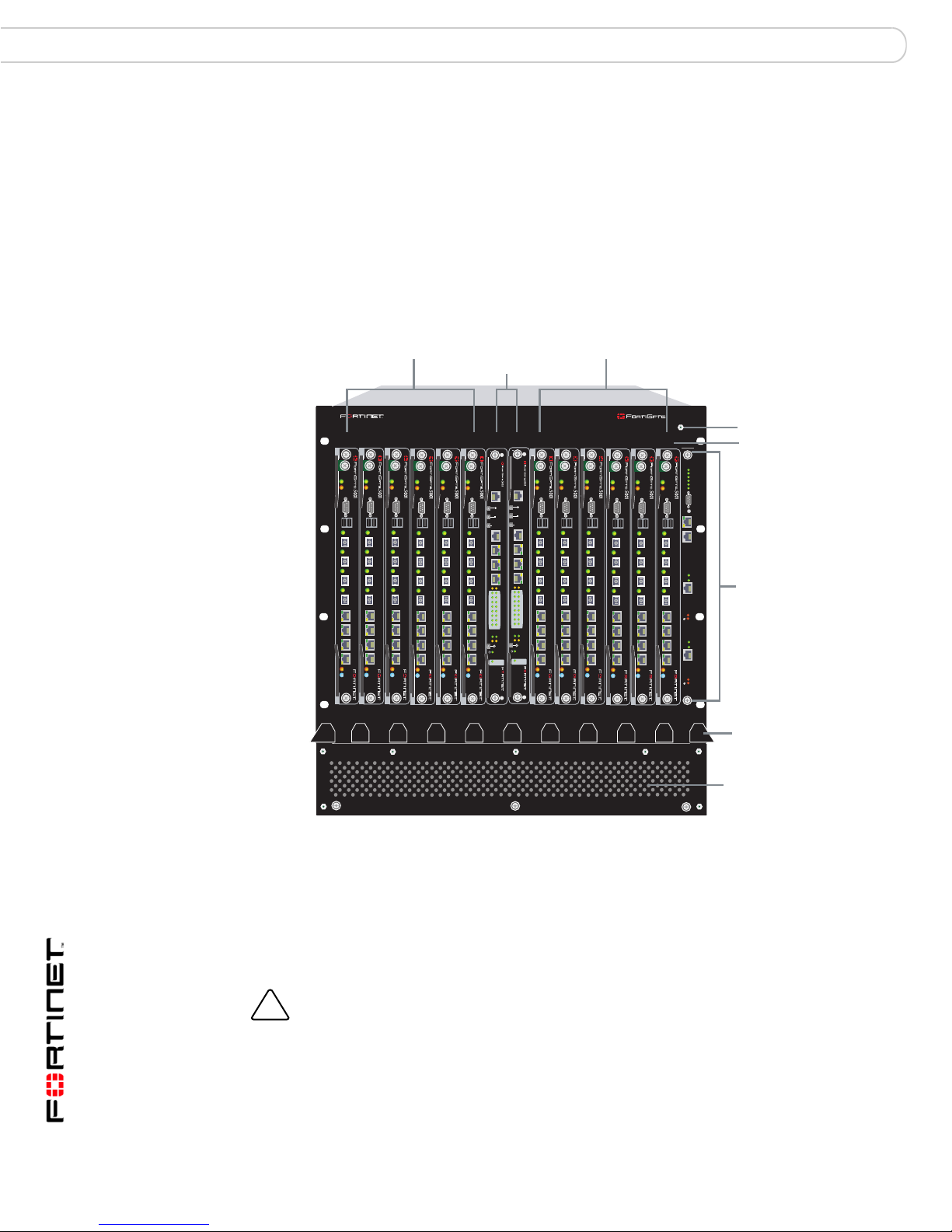
FortiGate-5140 chassis front panel
Figure 1 shows the front of a FortiGate-5140 chassis. Two FortiSwitch-5003
modules are installed in slots 1 and 2. Twelve FortiGate-5001SX modules are
installed in slots 3 to 14.
The FortiGate-5140 Shelf Manager is also visible. The FortiGate-5140 Shelf
Manager is a factory installed component that manages power distribution,
cooling, alarms, and shelf status for the FortiGate-5140 chassis.
Figure 1: FortiGate-5140 chassis front panel
FortiGate-5001SX
modules
slots 3, 5, 7, 9,
11, and 13
FortiSwitch-5003
modules
slots 1 and 2
FortiGate-5001SX
modules
slots 4, 6, 8, 10,
12, and 14
5140
ESD socket
13 11 9 7 5 3 1 2 4 6 8 10 12 14
PWRACC
PWRACC
PWRACC
CONSOLE
USB
1 2 3 4 5 6 7 8
STA IPM
STA IPM
PWRACC
CONSOLE
CONSOLE
USB
USB
1 2 3 4 5 6 7 8
1 2 3 4 5 6 7 8
STA IPM
STA IPM
PWRACC
PWRACC
MANAGEMENT
CONSOLE
CONSOLE
CONSOLE
USB
USB
USB
1 2 3 4 5 6 7 8
STA IPM
SYSTEM
CONSOLE
1 2 3 4 5 6 7 8
1 2 3 4 5 6 7 8
E2
ZRE
FLT
LED MODE
STA IPM
PWRACC
MANAGEMENT
E
E
T
T
H
H
O
O
SYSTEM
CONSOLE
R
R
S
S
2
2
3
3
2
2
Z
Z
R
R
E
E
0
0
Z
Z
R
R
E
E
1
1
Z
Z
R
R
E
E
2
2
E1
E2
E1
1514
1514
1312
1312
1110
1110
98
98
76
76
54
54
32
32
10
10
ZRE
OKCLK
OKCLK
INTEXT
INTEXT
FLT
FLT
FLT
HOT SWAP
HOT SWAP
RESET
RESET
LED MODE
STA IPM
PWRACC
PWRACC
CONSOLE
CONSOLE
USB
USB
1 2 3 4 5 6 7 8
1 2 3 4 5 6 7 8
STA IPM
STA IPM
PWRACC
PWRACC
CONSOLE
USB
1 2 3 4 5 6 7 8
CONSOLE
CONSOLE
USB
USB
1 2 3 4 5 6 7 8
1 2 3 4 5 6 7 8
STA IPM
STA IPM
Crit.
Maj.
Min.
PWRACC
3
2
1
CONSOLE
Alarms
Rst
USB
1 2 3 4 5 6 7 8
Link
Act
100
ETH 0
Prim.
ShMC
Stat.
Link
Act
100
ETH 0
STA IPM
Sec.
ShMC
Stat.
Slot
numbers
FortiGate-5140
Shelf Manager
Front cable
tray
3 hot-swappable
cooling fan trays
(numbered 0, 1, and
2 behind panel)
Also visible on the front of the FortiGate-5140:
• Electrostatic discharge (ESD) socket, used for connecting an ESD wrist or
ankle band when working with the chassis.
• Front cable tray, used for managing a nd securing ethernet and other cables.
• The location of the three hot swappable FortiGate-5140 cooling fan trays
behind the lower panel.
Caution: Do not operate the FortiGate-5140 chassis with open slots on the front panel. For
optimum cooling performance and safety, the slots must contain a FortiGate-5000 series
module or a cover and the removable power supply panel must be installed.
FortiGate-5000 Series Hardware Guide
12 01-00000-0293-20060315
FortiGate-5140 chassis FortiGate-5140 chassis back panel
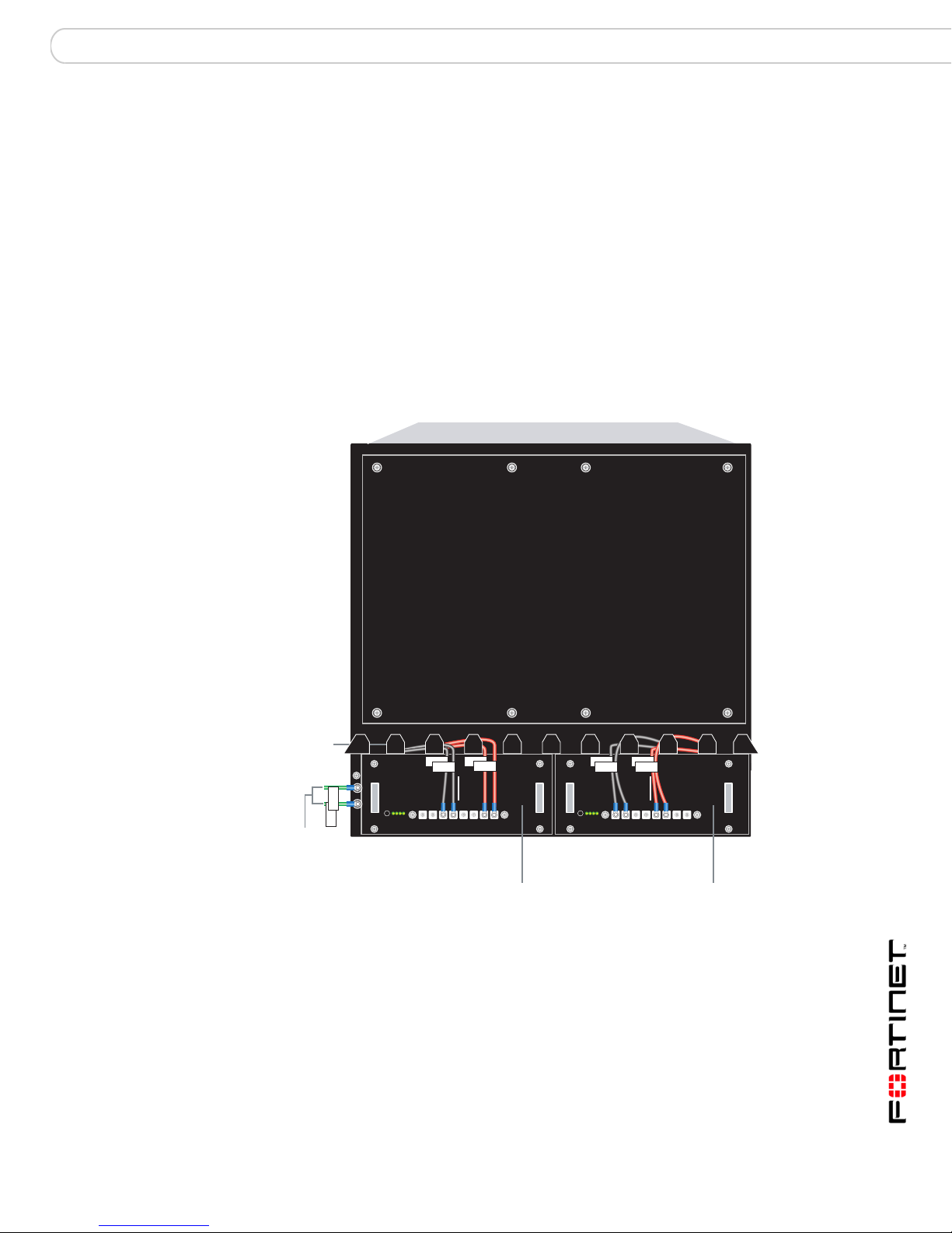
FortiGate-5140 chassis back panel
Figure 2 shows the back panel of the FortiGate-5140 chassis. The back panel
includes two hot-swappable redundant -48V/-60 VDC power entry modules
(PEMs) labelled PEM A and PEM B. Fortinet ships the FortiGate-5140 chassis
with PEM A and PEM B installed. The PEMs provide redundant DC power
connections for the FortiGate-5140 chassis and distribute DC powe r to the fan
trays and to the FortiGate-5000 series modules installed in the FortiGate-5140
chassis.
The power entry modules are hot swappable, which means yo u can remove and
replace a defective PEM while the FortiGate-5140 is operating assuming that the
FortiGate-5140 system has both PEMs connected to DC power for redundancy.
When operating, the power entry modules are covere d with protection pl ates. The
power entry modules are shown in the Figure 2 with protection plates removed.
Figure 2: FortiGate-5140 chassis back panel
Back cable
tray
GND
GND
Ground
connectors
(green)
-48V
-48V
-48V/-60 VDC nom RTN
HS
HS
Alarm
operate
-48V/-60 VDC
nom (black)
BPEM PEM
RTN
RTN
RTN
(red)
12341234
12341234
HS
-48V/-60 VDC
nom (black)
RTN
-48V
-48V
RTN
-48V/-60 VDC nom RTN
HS
Alarm
operate
Power
Entry Module B
(protection
plate removed)
(red)
A
12341234
12341234
RTN
Power
Entry Module A
(protection
plate removed)
The back panel also includes two ground connectors and the back cable tray.
Both ground connectors must be connected to Data Center ground. Use the back
cable tray for securing and managing DC power, RTN, and ground wires.
FortiGate-5000 Series Hardware Guide
01-00000-0293-20060315 13
Physical description of the FortiGate-5140 chassis FortiGate-5140 chassis
!
!
Physical description of the FortiGate-5140 chassis
The FortiGate-5140 chassis is a 12U chassis that can be installed in a standard
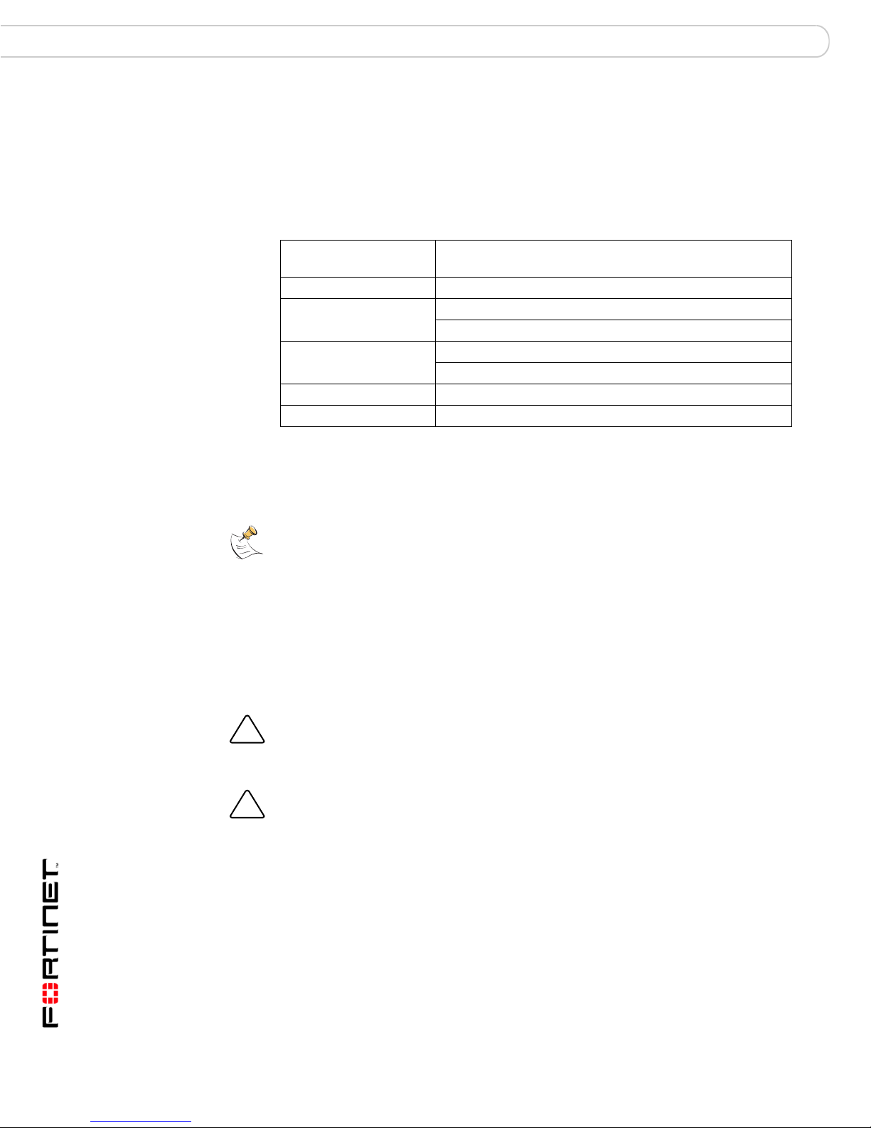
19-inch rack. Table 1 describes the physical characteristics of the FortiGate-5140
chassis.
Table 1: FortiGate-5140 chassis physical description
Dimensions 21 x 19 x 16.8 in. (53.3 x 48.3 x 42.7 cm)
(H x W x D)
Weight 64.5 lb. (29.3 kg)
Operating environment Temperature: 32 to 104°F (0 to 40°C)
Relative humidity: 5 to 95% (Non-condensing)
Storage environ m ent Temperature: -13 to 158 °F (-25 to 70°C)
Relative humidity: 5 to 95% (Non-condensing)
Power consumption Maximum: 2,980W DC
Power input 2x redundant -48VDC to -58VDC
Mounting the FortiGate-5140 chassis
Note: Mount the FortiGate chassis before installing the FortiGate-5000 series modules.
The FortiGate-5140 chassis must be mounted in a standard 19-inch rack. The
chassis requires 12U of vertical space in the rack.
If you install the FortiGate-5140 chassis in a closed or multi-unit rack assembly,
the operating ambient temperature of the rack environment may be greater than
room ambient temperature. Make sure the operating ambient temperature does
not exceed the manufacturer's maximum rated ambient temperature.
Caution: The FortiGate-5140 chassis should not be operated as a free-standing appliance.
Caution: Install the FortiGate-5140 chassis at the lower positions in the rack to avoid
making the rack top-heavy and potentially falling over.
Air flow
For rack installation, make sure that the amount of air flow required for safe
operation of the FortiGate-5140 chassis is not compromised.
FortiGate-5000 Series Hardware Guide
14 01-00000-0293-20060315

FortiGate-5140 chassis Connecting a FortiGate-5140 chassis to Data Center DC power and Data Center ground
Connecting a FortiGate-5140 chassis to Data Center DC power
and Data Center ground
Connect the FortiGate-5140 chassis to Data Center DC power (also called battery
power) using the redundant power entry modules (PEMs). Fortinet supplies and
recommends AWG-14 stranded wires for all power connections. Black for
-48VDC, red for RTN, and green for ground. If required, install term inal lugs on the
wires before connecting them to the PEM terminal strips. If you are connecting
both PEMs the -48VDC and RTN terminals on PEM A and PEM B must be wired
symmetrically.
This section describes:
• Connecting FortiGate-5140 power zones
• Connecting a FortiGate-5140 PEM to Data Center DC power
• Connecting the FortiGate-5140 chassis to Data Center ground
Connecting FortiGate-5140 power zones
Each FortiGate-5140 PEM includes 4 connectors that connect power to 4 differen t
power zones in the FortiGate-5140 chassis. Each power zone supplies power to
different FortiGate-5140 slo ts a nd cooling fan trays. You can connect the power in
a number of configurations depending on the requirements of a particular
installation.
Power zone 1 provides power to:
• Fan Tray 0 and Fan tray 1
• Slots 9, 11, 13 (see Figure 1)
Power zone 2 provides power to:
• Slots 1, 3, 5, 7 (see Figure 1)
Power zone 3 provides power to:
•Fan tray 2
• Slots 2, 4, 6, and 8 (see Figure 1)
Power zone 4 provides power to:
• Slots 10, 12, 14 (see Figure 1)
• Shelf manager
You can choose to connect power only to the power zones that you require. For
example, if your FortiGate-5140 chassis contains a FortiSwitch-5003 module in
slot 1 and four FortiGate-5001SX modules in slots 2, 3, 4, and 5 you would need
to connect the following power zones:
• Power zone 2 (for slots 1, 3, and 5)
• Power zone 3 (for fan tray 2 and slots 2 and 4)
• Power zone 4 (shelf manager)
This arrangement provides power to all occupied slots and should also p rovide
enough cooling for this configuration. If you want more or redundant cooling, you
can also connect power zone 1.
FortiGate-5000 Series Hardware Guide
01-00000-0293-20060315 15

Connecting a FortiGate-5140 chassis to Data Center DC power and Data Center ground FortiGate-5140 chassis
If you are connecting both PEMs the -48VDC and RTN terminals on PEM A and
PEM B must be wired symmetrically. This means that the connections must be the
same to both PEMs. For example, if you are planning on connecting powe r zones
1 and 2, you should use -48VDC and R TN connectors 1 and 2 on both PEM A and
PEM B. You should not connect to power zone 1 of PEM A and power zone 2 of
PEM B.
If a FortiGate-5140 chassis contains one FortiGate-5003 module it would be
installed in logical slot 1 and receive power from power zone 2. You could also
install two FortiGate-5001SX modules in logical slots 3 and 5 to also rece ive
power from power zone 2.
As a result, to supply power to this FortiGate-5140 configuration, you would need
to supply power to power zone 2 for the FortiGate-5003 and the FortiGate5001SX modules.You would also need to supply power to power zone 1 or 3 to
supply power to the fan trays.
FortiGate-5140 PEMs are hot-swappable, which means you can remove and
replace a defective PEM while the system is operating (assuming that the
FortiGate-5140 system has a DC PEM connected for redundancy). It is not
necessary to notify the software or reset the system power. You can add, remove,
or replace a second PEM while the system maintains all routing information and
ensures session preservation.
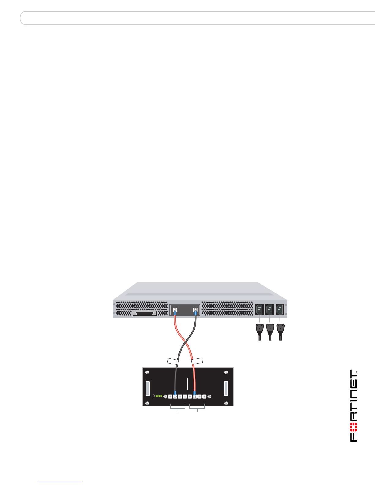
Connecting a FortiGate-5140 PEM to Data Center DC power
The following procedure describes how to connect power to power zones 1 and 2
of one PEM.
To connect a FortiGate-5140 PEM to Data Center DC power
You need the following tools and equipment to connect a FortiGate-5140 PEM to
Data Center DC power:
• A number 2 Phillips screwdriver.
• An electrostatic discharge (ESD) preventive wrist or ankle strap with
connection cord.
• The required number of red and black AWG-14 stranded wires with terminal
lugs attached.
FortiGate-5000 Series Hardware Guide
16 01-00000-0293-20060315
FortiGate-5140 chassis Connecting a FortiGate-5140 chassis to Data Center DC power and Data Center ground
Figure 3: Connecting a FortiGate-5140 PEM to Data Center DC power
Data Center
-48VDC
connector
Data Center
RTN connector
-48V/-60 VDC
black to Data
Center -48VDC
-48V
-48V
RTN (positive)
RTN
RTN
red to Data
Center RTN
-48V/-60 VDC nom RTN
HS
HS
Alarm
operate
-48V/-60 VDC nom
terminal strip
connectors
1, 2, 3, 4
12341234
12341234
RTN (positive)
terminal strip
connectors
1, 2, 3, 4
1 Attach the ESD wrist strap to your wrist and to an ESD socket or to a bare metal
surface on the chassis or frame.
2 Loosen the screws and remove the protection plate.
3 Connect the power wires. For example, to connect power zones 1 and 2 (see
Figure 3):
• Connect a black -48V power wire from the Data Center DC power source to
connector 1 on the FortiGate-5140 PEM terminal strip labeled -48V/-60 VDC
nom.
• Connect a black -48V power wire from the Data Center DC power source to
connector 2 on the FortiGate-5140 PEM terminal strip labeled -48V/-60 VDC
nom.
• Connect a red RTN return wire from Data Center RTN to connector 1 on the
FortiGate-5140 PEM terminal strip labeled RTN.
• Connect a red RTN return wire from Data Center RTN to connector 2 on the
FortiGate-5140 PEM terminal strip labeled RTN.
4 Secure the power cabling to the chassis using tie wraps and the back cable tray.
5 Optionally label the black wires -48V.
6 Optionally label the red wires RTN.
7 Re-attach the protection plate.
Connecting the FortiGate-5140 chassis to Data Center ground
The FortiGate-5140 chassis has two ground connections on the lowe r right side of
the FortiGate-5140 back panel (see Figure 2 on page 13). Both of these
connectors must be connected to Data Center ground.
FortiGate-5000 Series Hardware Guide
01-00000-0293-20060315 17
Connecting the FortiGate-5140 chassis to AC power using the FortiGate-5053 power converter tray FortiGate-5140 chassis
To connect the FortiGate-5140 chassis to Data Center ground
You need the following tools and equipment to connect the FortiGate-5140
chassis to ground:
• A number 2 Phillips screwdriver.
• An electrostatic discharge (ESD) preventive wrist or ankle strap with
connection cord.
• Two green AWG-14 stranded wires with terminal lugs attached.
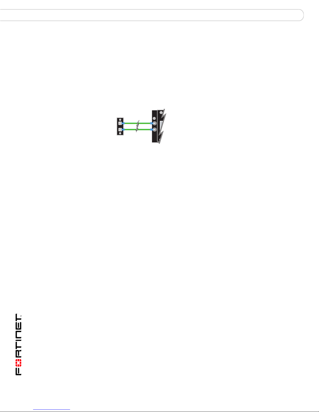
Figure 4: Connecting a FortiGate-5140 chassis to Data Center ground
FortiGate-5140
Ground
Data Center
ground
connectors
1 Attach the ESD wrist strap to your wrist and to an ESD socket or to a bare metal
surface on the chassis or frame.
2 Connect both green ground wires from the Data Center ground to the ground
connectors on the FortiGate-5140 chassis (see Figure 4).
3 Secure the ground wires to the chassis using tie wraps and the back cable tray.
connectors
4 Optionally label the wires GND.
Connecting the FortiGate-5140 chassis to AC power using the
FortiGate-5053 power converter tray
If Data Center DC power is not available, you can use the FortiGate-5053 power
converter tray with FortiGate-5140 power supplies (shown in Figure 5) to convert
AC power to DC power. The FortiGate-5053 power converter tray and the power
supplies are not supplied with the FortiGate-5140 chassis and must be purchased
separately.
This section contains the following information about the FortiGate-5140 chassis
and the FortiGate-5053 power converter tray:
• FortiGate-5053 power converter tray front and back panel
• Selecting the power supplies and power convertor trays that you need for your
FortiGate-5140 configuration
• Connecting a FortiGate-5140 chassis to the FortiGate-5053 power converter
tray
FortiGate-5053 power converter tray front and back panel
The front panel of the FortiGate-5053 power converter tray (shown in Figure 5)
provides access to the FortiGate-5140 power supplies.
FortiGate-5000 Series Hardware Guide
18 01-00000-0293-20060315
FortiGate-5140 chassis Connecting the FortiGate-5140 chassis to AC power using the FortiGate-5053 power converter tray
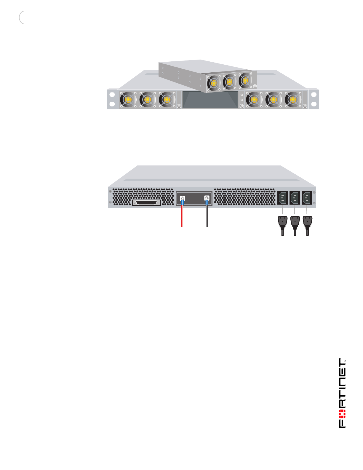
Figure 5: Front panel of the FortiGate-5053 power converter tray with one po wer
supply removed
Slot 3
The back panel of the FortiGate-5053 (shown in Figure 6) includes one DC power
connector terminal consisting of a RTN connector and a -48VDC connector. The
-48VDC connector is labelled -V. The RTN connector is not labelled.
Figure 6: Back panel of the FortiGate-5053 power converter tray
Slot 2
Slot 1
24 VAC 1 2 3
V-
Positive
(RTN)
(red)
-48V/-58 VDC
V-
(black)
DC out
AC in
The back panel also includes three AC power connectors, numbered 1, 2, 3.
The AC connector numbering corresponds to the slot numbering showing in
Figure 5. Each connector connects AC power directly to a FortiGate-5140 power
supply. The FortiGate-5053 can contain 1, 2, or 3 FortiGate-5140 power supplies
depending on your requirements. You should only connect AC power to the power
supplies that are installed.
AC input power characteristics:
• AC input voltage: 110 to 250 VAC
• AC input current: 10A
• Frequency: 47 to 63 Hz
Selecting the power supplies and power convertor trays that you need for
your FortiGate-5140 configuration
This section provides some basic information for determining how many
FortiGate-5053 power converter trays and FortiGate-5140 power supplies that
you need, depending on the power requirements of your FortiGate-5140 chassis.
This section provides guidelines only. Actual requirements may vary depending
on your installation requirements. Contact Fortinet Technical Support if you need
more information.
FortiGate-5000 Series Hardware Guide
01-00000-0293-20060315 19
Connecting the FortiGate-5140 chassis to AC power using the FortiGate-5053 power converter tray FortiGate-5140 chassis
The FortiGate-5053 power converter tray contains space for up to three
FortiGate-5140 power supplies. A FortiGate-5140 power supply converts AC
power to -48 VDC power. Each FortiGate-5140 power supply provides 1200W of
power.
The FortiGate-5053 power converter tray uses 2 + 1 power supply redundancy.
If three FortiGate-5140 power supplies are installed in a FortiGate-5053 power
converter tray, the first two power supplies provide a total of 2400W (2 x 1200W)
of power. The third power supply is the redundant backup.
The maximum power output for a FortiGate-5053 power converter tray with
FortiGate-5140 power supplies is 2400W; which can be achieved with two
FortiGate-5140 power supplies. If you need 2400W of power and power supply
redundancy, you can add a third FortiGate-5140 power supply.
Individual power requirements vary. If 1200W is enough power and redundancy is
not required, you require one FortiGate-5053 power converter tray and one
FortiGate-5140 power supply.
If 1200W is sufficient but a redundant power supply is required, you can add a
second FortiGate-5140 power supply . This second power supply will also cover
power requirements between 1200 and 2400W. If you require redundant power
greater than 1200W you can add a third FortiGate-5140 power supply.
Basic power requirements
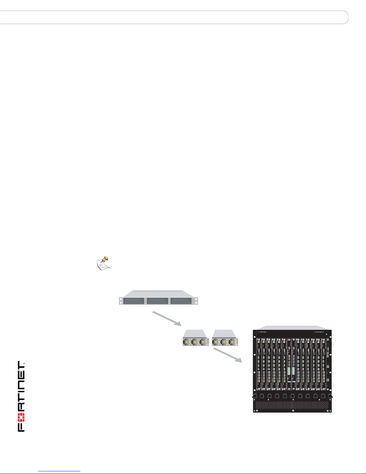
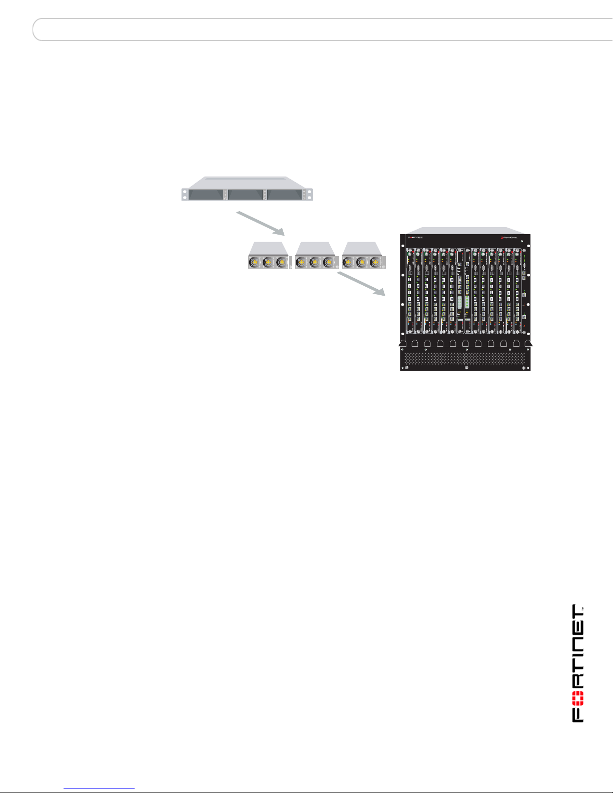
To supply enough power for a FortiGate-5140 chassis with a total of 14 FortiGate
and FortiSwitch modules you require one FortiGate-5053 power converter tray
and two FortiGate-5140 power supplies (see Figure 7). The FortiGate-5140 power
supplies are installed in FortiGate-5053 slots 1 and 2. This configuration supplies
2400W of power to the FortiGate-5140 chassis.
Note: If your will not be filling all of the FortiGate-5140 slots you may not need both
FortiGate-5140 power supplies.
Figure 7: Non-redundant power for all FortiGate-5140 chassis slots
1 FortiGate-5053
power convertor tray
1 FortiGate-5140
chassis
13 11 9 7 5 3 1 2 4 6 8 10 12 14
PWRACC
PWRACC
PWRACC
CONSOLE
CONSOLE
USB
USB
1 2 3 4 5 6 7 8
1 2 3 4 5 6 7 8
STAIPM
STAIPM
PWRACC
PWRACC
PWRACC
MANAGEMENT
CONSOLE
CONSOLE
CONSOLE
CONSOLE
USB
USB
USB
USB
SYSTEM
CONSOLE
1 2 3 4 5 6 7 8
1 2 3 4 5 6 7 8
1 2 3 4 5 6 7 8
1 2 3 4 5 6 7 8
E1
E2
1514
1312
1110
98
76
54
32
10
ZRE
OKCLK
INTEXT
FLT
FLT
HOT SWAP
RESET
STAIPM
LED MODE
STAIPM
STAIPM
STAIPM
PWRACC
PWRACC
PWRACC
MANAGEMENT
E
E
T
T
H
H
O
O
CONSOLE
USB
SYSTEM
CONSOLE
R
R
S
S
2
2
3
3
2
2
1 2 3 4 5 6 7 8
Z
Z
R
R
E
E
0
0
Z
Z
R
R
E
E
1
1
Z
Z
R
R
E
E
2
2
E1
E2
1514
1312
1110
98
76
54
32
10
ZRE
OKCLK
INTEXT
FLT
FLT
HOT SWAP
RESET
LED MODE
STAIPM
PWRACC
PWRACC
CONSOLE
CONSOLE
CONSOLE
CONSOLE
USB
USB
USB
USB
1 2 3 4 5 6 7 8
1 2 3 4 5 6 7 8
1 2 3 4 5 6 7 8
1 2 3 4 5 6 7 8
STAIPM
STAIPM
STAIPM
STAIPM
5140
Crit.
Maj.
Min.
PWRACC
3
2
1
CONSOLE
Alarms
Rst
USB
1 2 3 4 5 6 7 8
Link
Act
100
ETH 0
Prim.
ShMC
Stat.
Link
Act
100
ETH 0
STAIPM
Sec.
ShMC
Stat.
2 FortiGate-5140
power supplies
2 x 1200W = 2400W
Slot 1Slot 2Slot 3
FortiGate-5000 Series Hardware Guide
20 01-00000-0293-20060315
FortiGate-5140 chassis Connecting the FortiGate-5140 chassis to AC power using the FortiGate-5053 power converter tray
Redundant FortiGate-5140 power supplies
You can supply redundant power to a FortiGate-5140 chassis by adding a third
FortiGate-5140 power supply to the FortiGate-5053 power converter tray
(see Figure 8). If one of the FortiGate-5140 power supplies in the FortiGate-5053
power converter tray fails, the third power supply takes its place without a power
interruption.
Figure 8: 2 + 1 redundant FortiGate-5140 power supplies
1 FortiGate-5053
Slot 1Slot 2Slot 3
power convertor tray
3 FortiGate-5140
power supplies
2 x 1200W = 2400W
2 + 1 redundancy
1 FortiGate-5140
chassis
13 11 9 7 5 3 1 2 4 6 8 10 12 14
PWRACC
PWRACC
PWRACC
CONSOLE
CONSOLE
USB
USB
1 2 3 4 5 6 7 8
1 2 3 4 5 6 7 8
STAIPM
STAIPM
PWRACC
PWRACC
PWRACC
MANAGEMENT
CONSOLE
CONSOLE
CONSOLE
CONSOLE
USB
USB
USB
USB
SYSTEM
CONSOLE
1 2 3 4 5 6 7 8
1 2 3 4 5 6 7 8
1 2 3 4 5 6 7 8
1 2 3 4 5 6 7 8
E2
1514
1312
1110
98
76
54
32
10
ZRE
OKCLK
INTEXT
FLT
FLT
HOT SWAP
RESET
STAIPM
LED MODE
STAIPM
STAIPM
STAIPM
PWRACC
PWRACC
PWRACC
MANAGEMENT
E
E
T
T
H
H
O
O
CONSOLE
USB
SYSTEM
CONSOLE
R
R
S
S
2
2
3
3
2
2
1 2 3 4 5 6 7 8
Z
Z
R
R
E
E
0
0
Z
Z
R
R
E
E
1
1
Z
Z
R
R
E
E
2
2
E1
E2
E1
1514
1312
1110
98
76
54
32
10
ZRE
OKCLK
INTEXT
FLT
FLT
HOT SWAP
RESET
LED MODE
STAIPM
PWRACC
PWRACC
CONSOLE
CONSOLE
CONSOLE
CONSOLE
USB
USB
USB
USB
1 2 3 4 5 6 7 8
1 2 3 4 5 6 7 8
1 2 3 4 5 6 7 8
1 2 3 4 5 6 7 8
STAIPM
STAIPM
STAIPM
STAIPM
Crit.
Maj.
Min.
PWRACC
3
2
1
CONSOLE
Alarms
Rst
USB
1 2 3 4 5 6 7 8
Link
Act
100
ETH 0
Prim.
ShMC
Stat.
Link
Act
100
ETH 0
STAIPM
Sec.
ShMC
Stat.
Redundant FortiGate-5053 power converter trays
A single FortiGate-5053 power converter tray is usually only connected to one
FortiGate-5140 PEM. If this PEM or FortiGate-5053 power converter tray fails or is
disconnected the FortiGate-5140 chassis will loose power.
Y ou can sup ply redundant power to the entire FortiGate-5140 chassis by adding a
second FortiGate-5053 power converter containing two or three FortiGate-5140
power supplies and connected this FortiGate-5053 power converter tray to the
second FortiGate-5140 PEM.
5140
FortiGate-5000 Series Hardware Guide
01-00000-0293-20060315 21

Connecting the FortiGate-5140 chassis to AC power using the FortiGate-5053 power converter tray FortiGate-5140 chassis
Figure 9: Redundant FortiGate-5053 power converter trays
Slot 1Slot 2Slot 3
2 FortiGate-5053
power convertor trays
Slot 1Slot 2Slot 3
4 FortiGate-5140
power supplies
2 x 1200W = 2400W
13 11 9 7 5 3 1 2 4 6 8 10 12 14
PWRACC
PWRACC
2 x 1200W = 2400W
1 FortiGate-5140
chassis
PWRACC
CONSOLE
CONSOLE
USB
USB
1 2 3 4 5 6 7 8
1 2 3 4 5 6 7 8
STAIPM
STAIPM
PWRACC
PWRACC
PWRACC
MANAGEMENT
E
T
H
CONSOLE
USB
1 2 3 4 5 6 7 8
STAIPM
O
CONSOLE
CONSOLE
CONSOLE
USB
USB
USB
SYSTEM
CONSOLE
R
S
2
3
2
1 2 3 4 5 6 7 8
1 2 3 4 5 6 7 8
1 2 3 4 5 6 7 8
Z
R
E
0
Z
R
E
1
Z
R
E
2
E1
E2
1514
1312
1110
98
76
54
32
10
ZRE
OKCLK
INTEXT
FLT
FLT
HOT SWAP
RESET
LED MODE
STAIPM
STAIPM
STAIPM
PWRACC
PWRACC
PWRACC
MANAGEMENT
E
T
H
O
CONSOLE
USB
SYSTEM
CONSOLE
R
S
2
3
2
1 2 3 4 5 6 7 8
Z
R
E
0
Z
R
E
1
Z
R
E
2
E1
E2
1514
1312
1110
98
76
54
32
10
ZRE
OKCLK
INTEXT
FLT
FLT
HOT SWAP
RESET
LED MODE
STAIPM
PWRACC
PWRACC
CONSOLE
CONSOLE
CONSOLE
CONSOLE
USB
USB
USB
USB
1 2 3 4 5 6 7 8
1 2 3 4 5 6 7 8
1 2 3 4 5 6 7 8
1 2 3 4 5 6 7 8
STAIPM
STAIPM
STAIPM
STAIPM
Figure 10: Redundant FortiGate-5053 power converter trays and 2 + 1 redundant
FortiGate-5140 power supplies
5140
Crit.
Maj.
Min.
PWRACC
3
2
1
CONSOLE
Alarms
Rst
USB
1 2 3 4 5 6 7 8
Link
Act
100
ETH 0
Prim.
ShMC
Stat.
Link
Act
100
ETH 0
STAIPM
Sec.
ShMC
Stat.
2 x 1200W = 2400W
2 + 1 redundancy
2 x 1200W = 2400W
2 + 1 redundancy
Slot 1Slot 2Slot 3
Slot 1Slot 2Slot 3
2 FortiGate-5053
power convertor trays
6 FortiGate-5140
power supplies
1 FortiGate-5140
chassis
13 11 9 7 5 3 1 2 4 6 8 10 12 14
PWRACC
PWRACC
PWRACC
CONSOLE
CONSOLE
USB
USB
1 2 3 4 5 6 7 8
1 2 3 4 5 6 7 8
STAIPM
STAIPM
PWRACC
PWRACC
PWRACC
MANAGEMENT
CONSOLE
CONSOLE
CONSOLE
CONSOLE
USB
USB
USB
USB
SYSTEM
CONSOLE
1 2 3 4 5 6 7 8
1 2 3 4 5 6 7 8
1 2 3 4 5 6 7 8
1 2 3 4 5 6 7 8
E2
E1
1514
1312
1110
98
76
54
32
10
ZRE
OKCLK
INTEXT
FLT
FLT
HOT SWAP
RESET
STAIPM
LED MODE
STAIPM
STAIPM
STAIPM
PWRACC
PWRACC
PWRACC
MANAGEMENT
E
E
T
T
H
H
O
O
CONSOLE
USB
SYSTEM
CONSOLE
R
R
S
S
2
2
3
3
2
2
1 2 3 4 5 6 7 8
Z
Z
R
R
E
E
0
0
Z
Z
R
R
E
E
1
1
Z
Z
R
R
E
E
2
2
E1
E2
1514
1312
1110
98
76
54
32
10
ZRE
OKCLK
INTEXT
FLT
FLT
HOT SWAP
RESET
LED MODE
STAIPM
PWRACC
PWRACC
CONSOLE
CONSOLE
CONSOLE
CONSOLE
USB
USB
USB
1 2 3 4 5 6 7 8
1 2 3 4 5 6 7 8
1 2 3 4 5 6 7 8
1 2 3 4 5 6 7 8
STAIPM
STAIPM
STAIPM
STAIPM
5140
Crit.
Maj.
Min.
PWRACC
3
2
1
CONSOLE
Alarms
Rst
USB
USB
1 2 3 4 5 6 7 8
Link
Act
100
ETH 0
Prim.
ShMC
Stat.
Link
Act
100
ETH 0
STAIPM
Sec.
ShMC
Stat.
FortiGate-5000 Series Hardware Guide
22 01-00000-0293-20060315
FortiGate-5140 chassis Connecting the FortiGate-5140 chassis to AC power using the FortiGate-5053 power converter tray
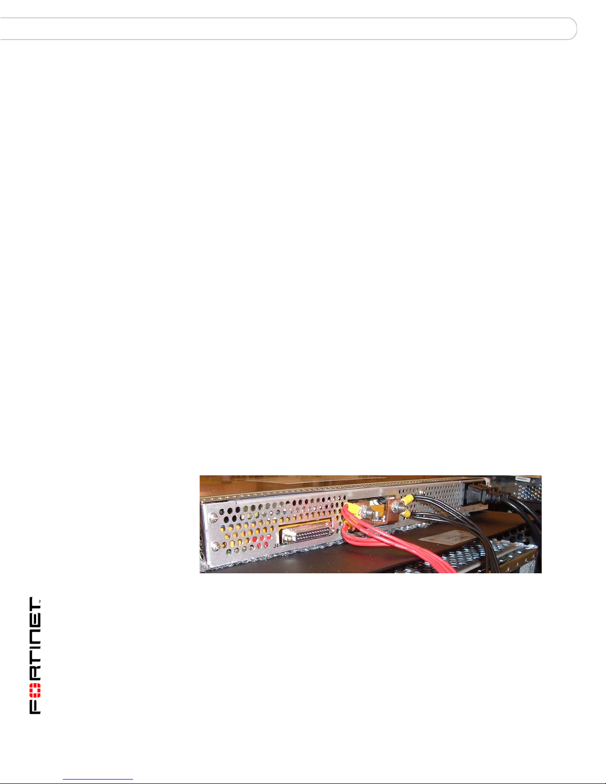
Connecting a FortiGate-5140 chassis to the FortiGate-5053 power converter
tray
To use a FortiGate-5053 power converter tray with the FortiGate-5140 chassis
you need to make DC power connections between the FortiGate-5140 chassis
and the FortiGate-5053 power converter tray. You also need to the connect the
FortiGate-5140 chassis to Data Center ground.
If you are connecting both PEMs and connecting mu ltip le power zo ne s, the
-48VDC and RTN terminals on PEM A and PEM B must be wired symmetrically.
See “Connecting FortiGate-5140 power zones” on page 15 for information about
FortiGate-5140 power zones.
To connect a FortiGate-5140 PEM to a FortiGate-5053 power converter tray
Each PEM includes four connectors that connect power to four different power
zones in the FortiGate-5140 chassis. Each power zone supplies power to dif ferent
FortiGate-5140 slots and cooling fan trays. Power can be co nnected in a number
of configurations depending on the requirements of a particular installation. The
following procedure describes how to connect power to power zones 3 and 4 of
one PEM.
You need the following tools and equipment to connect a FortiGate-5140 PEM to
a FortiGate-5053 power converter tray:
• A number 2 Phillips screwdriver.
• An electrostatic discharge (ESD) preventive wrist or ankle strap with
connection cord.
• The required number of red and black AWG-14 stranded wires with terminal
lugs attached.
• A FortiGate-5053 power converter tray containing two or th ree FortiGa te-5140
power supplies and mounted in a rack near the FortiG at e- 5 140 ch ass i s.
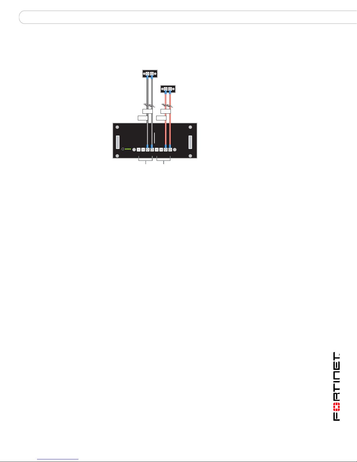
Figure 11: Connect a FortiGate-5140 PEM to a FortiGate-5053 power converter tray
24 VAC 1 2 3
V-
(RTN)
(Red)
-48V/-60 VDC Black to
FortiGate-5053
-48/-58 VDC
-48V
-48V/-60 VDC nom RTN
HS
HS
Alarm
operate
-48V/-60 VDC
terminal strip
connectors
1, 2, 3, 4
V-
(Black)
RTN Red to
FortiGate-5053
RTN
RTN
12341234
12341234
RTN (positive)
terminal strip
connectors
1, 2, 3, 4
AC in
FortiGate-5000 Series Hardware Guide
01-00000-0293-20060315 23
Connecting the FortiGate-5140 chassis to AC power using the FortiGate-5053 power converter tray FortiGate-5140 chassis
1 Attach the ESD wrist strap to your wrist and to an ESD socket or to a bare metal
surface on the chassis or frame.
2 Loosen the screws and remove the protection plate from the FortiGate -5140 PEM.
3 Connect the wires. For example, to connect power zone 3 (see Figure 11):
• Connect a black DC power wire from the FortiGate-5053 power converter tray
V- terminal (the right connector) to connector 3 on the FortiGate-5140 PEM
terminal strip labeled -48V/-60 VDC nom.
• Connect a red return wire from the FortiGate-5053 power converter tray
unmarked connector (the left connector) to connector 3 on the FortiGate-5140
PEM terminal strip labeled RTN.
4 Secure the power wires to the chassis using tie wraps and the back cable tray.
5 Optionally label the black wires -48V.
6 Optionally label the red wires RTN.
7 Re-attach the protection plate to the FortiGate-5140 PEM.
8 Connect the FortiGate-5053 power converter tray to AC power.
To connect the FortiGate-5140 chassis to Data Center ground
The FortiGate-5053 power converter tray does not have a ground connector. So,
even if you are using a FortiGate-5053 power converter tray to supply DC power
to your FortiGate-5140, you must us e th e pr oc ed u re “Connecting the FortiGate-
5140 chassis to Data Center ground” on pa ge 17 to connect the FortiGate-5140 to
Data Center ground.
To supply power to multiple power zones
Each FortiGate-5053 power converter tray can supply power to multiple
FortiGate-5140 power zones by connecting multiple FortiGate-5140 power zones
to the same FortiGate-5053 powe r ter m ina l. Fo r ex ample, Figure 12 shows two
power connections from a FortiGate-5053 DC power terminal.
Figure 12: FortiGate-5053 power converter connecting to multiple power zones.
FortiGate-5000 Series Hardware Guide
24 01-00000-0293-20060315

FortiGate-5140 chassis Inserting FortiGate-5000 and FortiSwitch-5000 modules into a FortiGate-5140 chassis
!
!
Inserting FortiGate-5000 and FortiSwitch-5000 modules into a
FortiGate-5140 chassis
You can insert FortiGate-5000 series and FortiSwitch-5003 modules into the
FortiGate-5140 chassis. Arrange the modules in slots as required for your
configuration. FortiGate-5000 series modules can be installed in any
FortiGate-5140 slots. FortiSwitch-5003 modules can only be installed in slots 1
and 2.
Caution: FortiGate-5000 series and FortiSwitch-5000 series modules must be protected
from static discharge and physical shock. Only handle or work with FortiGate-5000 series
and FortiSwitch-5000 series modules at a static-free workstation. Always wear a grounded
electrostatic discharge (ESD) preventive wrist or ankle strap when handling FortiGate-5000
series or FortiSwitch-5000 series modules.
Caution: Do not operate the FortiGate-5140 chassis with open slots on the front panel. For
optimum cooling performance and safety, the slots must contain a FortiGate-5000 series
module or a cover and the removable power supply panel must be installed.
See the following sections for information about installing and removing the
following FortiGate-5000 series and FortiSwitch-5000 series modules:
FortiGate-5001SX:
• “Inserting a FortiGate-5001SX module into a chassis” on page 51
• “Removing a FortiGate-5001SX module from a chassis” on page 55
FortiGate-5001FA2:
• “Inserting a FortiGate-5001FA2 module into a chassis” on page 65
• “Removing a FortiGate-5001FA2 module from a chassis” on page69
FortiGate-5002FB2:
• “Inserting a FortiGate-5002FB2 module into a chassis” on page 77
• “Removing a FortiGate-5002FB2 module from a chassis” on page 80
FortiSwitch-5003
• “Inserting a FortiSwitch-5003 module into a chassis” on page 87
• “Removing a FortiSwitch-5003 module from a chassis” on page 90
FortiGate-5000 Series Hardware Guide
01-00000-0293-20060315 25

Inserting FortiGate-5000 and FortiSwitch-5000 modules into a FortiGate-5140 chassis FortiGate-5140 chassis
FortiGate-5000 Series Hardware Guide
26 01-00000-0293-20060315

FortiGate-5050 chassis FortiGate-5050 front panel
FortiGate-5050 chassis
The FortiGate-5050 chassis is a 5U 19-inch rack mount ATCA chassis that
includes five slots for up to five FortiGate-5000 series modules. If each FortiGate5000 module is operating as a standalone FortiGate system, you can install any
combination of FortiGate-5000 series modules in these 5 slots. If all five slots
contain FortiGate-5001SX modules, the FortiGate-5050 chassis provides a total
of 40 Gigabit ethernet FortiGate interfaces.
You can also install a FortiSwitch-5003 module in the FortiGate-5050 chassis to
provide HA heartbeat communications. A single FortiSwitch-5003 module can
provide HA heartbeat communications for up to three FortiGate-5000 series
modules in the chassis. You can add a second FortiSwitch-5003 module for
redundancy. The first FortiSwitch-5003 module is installed in slot 2, the second in
slot 1. If FortiSwitch-5003 modules are included you can install up to three
FortiGate-5000 series modules in slots 3, 4, and 5.
The FortiGate-5050 chassis requires -48VDC Data Center DC power . If DC power
is not available you can install a FortiGate-5053 power converter tray (purchased
separately) with FortiGate-5020/5050 power supplies.
This chapter describes the FortiGate-5050 chassis and includes the following
sections:
• FortiGate-5050 front panel
• FortiGate-5050 back panel
• Physical description of the FortiGate-5050 chassis
• Mounting the FortiGate-5050 chassis
• Connecting the FortiGate-5050 chassis to Data Center DC power and Data
Center ground
• Connecting the FortiGate-5050 chassis to AC power using the FortiGate-5053
power converter tray
• Inserting FortiGate-5000 and FortiSwitch-5000 modules into a FortiGate-5050
chassis
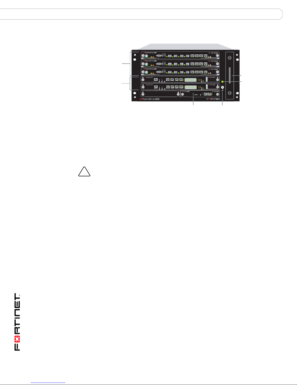
FortiGate-5050 front panel
Figure 13 shows the front of a FortiGate-5050 chassis. Two FortiSwitch-5003
modules are installed in slots 1 and 2. Three FortiGate-5001SX modules are
installed in slots 3, 4, and 5.
The FortiGate-5050 Shelf Manager is also visible. The FortiGate-5050 Shelf
Manager is a factory installed component that manages power distribution,
cooling, alarms, and shelf status for the FortiGate-5050 chassis.
FortiGate-5000 Series Hardware Guide
01-00000-0293-20060315 27
FortiGate-5050 back panel FortiGate-5050 chassis
!
Figure 13: FortiGate-5050 front panel
USB
1 2 3 4 5 6 7 8
FortiGate-5001SX
modules
slots 3, 4,
and 5
FortiSwitch-5003
modules
slots 1 and 2
CONSOLE
PWRACC
5
USB
1 2 3 4 5 6 7 8
4
3
2
1
ShMC
2
CONSOLE
PWRACC
USB
1 2 3 4 5 6 7 8
CONSOLE
PWRACC
ETH
O
MANAGEMENT
MANAGEMENT
ETH
O
RS232ZRE0ZRE1ZRE2
SYSTEM
CONSOLE
RS232ZRE0ZRE1ZRE2
SYSTEM
CONSOLE
E1
9876543210
1514
1312
1110
E2
E1
9876543210
1514
1312
1110
E2
STA IPM
STA IPM
STA IPM
OKCLK
INTEXT
FLT
HOT SWAP
RESET
ZRE
FLT
OKCLK
INTEXT
FLT
HOT SWAP
RESET
ZRE
FLT
Critical
Major
Minor
Alarm
Alarm
Console Ethernet
Reset
POWER
LED MODE
LED MODE
ShMC
Hot Swap
Status
1
Hot-swappable
cooling fan tray
Power LED
Also visible on the front of the FortiGate-5050:
• The location of the hot swappable FortiGate-5050 cooling fan tray behind
panel.
• Power LE D.
• ESD socket, used for connecting an ESD wrist or ankle band when working
with the chassis.
Caution: Do not operate the FortiGate-5050 chassis with open slots on the front panel. For
optimum cooling performance and safety, the slots must contain a FortiGate-5000 series
module or a cover and the removable power supply panel must be installed.
FortiGate-5050 back panel
The FortiGate-5050 chassis back panel includes two redundant -48V to - 58V DC
power input connectors labelled Input A and Input B. The power input connectors
provide redundant DC power connections for the FortiGate-5050 chassis and
distribute DC power to the fan tray and the FortiGate-5000 seri es modules
installed in the FortiGate-5050 chassis. Each power input connector includes a 25
Amp circuit breaker that also functions as an on/off switch for the power input
connector.
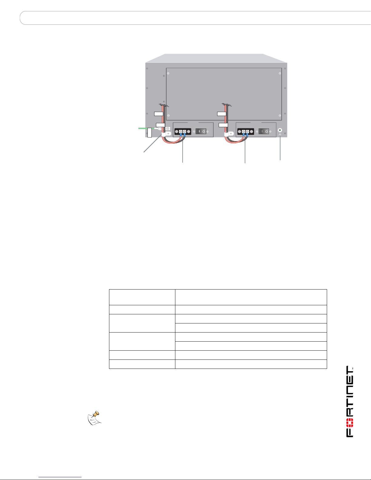
Figure 14 shows the ba ck of a FortiGate-5050 chassis. When operating, the
power input connectors are covered with clear protection plates.
FortiGate-5050
Shelf Manager
ESD socket
FortiGate-5000 Series Hardware Guide
28 01-00000-0293-20060315
FortiGate-5050 chassis Physical description of the FortiGate-5050 chassis
Figure 14: FortiGate-5050 chassis back panel
5
4
3
2
Ground
Connector
(green)
Power
fixture
wire
RTN
-48V
GND
Positive
1
(RTN)
(red)
INPUT A
DC VOLTAGE RANGE
-48V TO -58V
RTN (-DC IN)
-48V to -58V
(-DC in)
(black)
DC Power
Input A
25
AMP
RTN
-48V
Positive
(RTN)
(red)
INPUT B
DC VOLTAGE RANGE
-48V TO -58V
RTN (-DC IN)
-48V to -58V
(-DC in)
DC Power
Input B
(black)
25
AMP
ESD socket
The back panel also includes the FortiGate-5050 cha ssis ground connector which
must be connected to Data Center ground. Use the power wire fixtures for
securing and managing DC power wires. The FortiGate-5050 chassis also has a
second ESD socket on the back panel.
Physical description of the FortiGate-5050 chassis
The FortiGate-5050 chassis is a 5U chassis that can be installed in a standard
19-inch rack. Table 2 describes the physical characteristics of the FortiGate-5050
chassis.
Table 2: FortiGate-5050 chassis physical description
Dimensions 8.75 x 17 x 15.5 in. (13.3 x 43.2 x 39.4 cm)
(H x W x D)
Weight 26.75 lb. (12.1 kg)
Operating environment Temperature: 32 to 104°F (0 to 40°C)
Relative humidity: 5 to 95% (Non-condensing)
Storage environment Temperature: -13 to 158 °F (-25 to 70°C)
Relative humidity: 5 to 95% (Non-condensing)
Power consumption Maximum: 1,135 W
Power input 2x redundant -48VDC to -58VDC
Mounting the FortiGate-5050 chassis
Note: Mount the FortiGate chassis before installing the FortiGate-5000 series modules.
FortiGate-5000 Series Hardware Guide
01-00000-0293-20060315 29

Connecting the FortiGate-5050 chassis to Data Center DC power and Data Center ground FortiGate-5050 chassis
!
The FortiGate-5140 chassis must be mounted in a standard 19-inch rack. The
chassis requires 5U of vertical space in the rack.
If you install the FortiGate-5050 chassis in a closed or multi-unit rack assembly,
the operating ambient temperature of the rack environment may be greater than
room ambient temperature. Make sure the operating ambient temperature does
not exceed the manufacturer's maximum rated ambient temperature.
Caution: The FortiGate-5050 chassis should not be operated as a free-standing appliance.
Air flow
For rack installation, make sure that the amount of air flow required for safe
operation of the FortiGate-5050 chassis is not compromised.
Connecting the FortiGate-5050 chassis to Data Center DC power
and Data Center ground
Connect the FortiGate-5050 chassis to Data Center DC power (also called battery
power) using the redundant power input connectors. Fortinet supplies and
recommends AWG-14 stranded wires for all power connections. Black for
-48VDC, red for RTN, and green for ground. If require d, install terminal lugs on th e
wires before connecting them to the power input connectors.
To connect a FortiGate-5050 power input connector to Data Center DC
power
The following procedure describes how to connect one FortiGate-5050 power
input connector to Data Center DC power. For normal operation, only one power
input connector must be connected. For redundant DC power you can conn ect the
second power input connector to a dif ferent DC power source.
You need the following tools and equipment to connect a FortiGate-5050 power
input connector to Data Center DC power:
• A number 2 Phillips screwdriver.
• An electrostatic discharge (ESD) preventive wrist or ankle strap with
connection cord.
• The required number of red and black AWG-14 stranded wires with terminal
lugs attached.
FortiGate-5000 Series Hardware Guide
30 01-00000-0293-20060315
 Loading...