

Fortinet FortiGate-5000, FortiGate-5001SX, FortiGate-5001, FortiGate-5001A, FortiGate-5001FA2 Quick Manual
...Page 1
5
5
QUICK GUIDE
13 11 9 7 5 3 1 2 4 6 8 10 12 14
PWR
PWR
PWR
PWR
PWR
PWR
ACC
ACC
CONSOLE
USB
1 2
3 4
5 6 7 8
STA IPM
STA IPM
ACC
ACC
CONSOLE
CONSOLE
USB
USB
1 2
1 2
3 4
3 4
5 6 7 8
5 6 7 8
STA IPM
STA IPM
ACC
ACC
CONSOLE
CONSOLE
USB
USB
1 2
1 2
3 4
3 4
5 6 7 8
5 6 7 8
STA IPM
MANAGEMENT
MANAGEMENT
CONSOLE
E
E
T
T
H
H
O
O
USB
SYSTEM
SYSTEM
CONSOLE
CONSOLE
R
R
S
S
1 2
2
2
3
3
2
2
Z
Z
R
R
E
E
0
0
Z
Z
R
R
E
E
1
1
3 4
Z
Z
R
R
E
E
2
2
E2
E1
E2
E1
1514
1514
1312
1312
1110
1110
98
98
76
76
5 6 7 8
54
54
32
32
10
10
ZRE
ZRE
OKCLK
OKCLK
INTEXT
INTEXT
FLT
FLT
FLT
FLT
HOT SWAP
HOT SWAP
RESET
RESET
LED MODE
LED MODE
STA IPM
PWRACC
PWRACC
PWRACC
CONSOLE
CONSOLE
USB
USB
1 2 3 4 5 6 7 8
1 2 3 4 5 6 7 8
STA IPM
STA IPM
STA IPM
PWRACC
PWRACC
CONSOLE
1 2 3 4 5 6 7 8
CONSOLE
CONSOLE
USB
USB
USB
1 2 3 4 5 6 7 8
1 2 3 4 5 6 7 8
STA IPM
STA IPM
FortiGate-5000 Series
5140
USB
1 2 3 4 5 6 7 8
CONSOLE
PWRACC
5
Crit.
Maj.
Min.
PWRACC
3
2
1
CONSOLE
Alarms
Rst
USB
1 2 3 4 5 6 7 8
4
3
2
1
Link
Act
100
ETH 0
Prim.
ShMC
Stat.
Link
Act
100
ETH 0
STA IPM
Sec.
ShMC
Stat.
ShMC
2
USB
1 2 3 4 5 6 7 8
CONSOLE
PWRACC
USB
1 2 3 4 5 6 7 8
CONSOLE
PWRACC
ETH
O
RS232ZRE0ZRE1ZRE2
SYSTEM
CONSOLE
MANAGEMENT
ETH
O
RS232ZRE0ZRE1ZRE2
SYSTEM
CONSOLE
MANAGEMENT
USB
CONSOLE
RESET
STATUS
PWR
USB
CONSOLE
RESET
STATUS
PWR
162
162
E1
9876543210
1514
1312
1110
E2
E1
9876543210
1514
1312
1110
E2
3 4 5 6
3 4 5 6
STA IPM
STA IPM
STA IPM
OKCLK
INTEXT
FLT
HOT SWAP
RESET
ZRE
FLT
OKCLK
INTEXT
FLT
HOT SWAP
RESET
ZRE
FLT
Critical
Major
Minor
Alarm
Alarm
Console Ethernet
Reset
ON/OFF
IPM
ON/OFF
IPM
POWER
LED MODE
LED MODE
ShMC
Hot Swap
Status
1
PSUA
PSU B
ALT
ALT
A high-level guide to all three FortiGate-5000 series chassis and the FortiGate and FortiSwitch modules that you can
install in them. For detailed information about the FortiGate-5000 series hardware, see the FortiGate-5000 Series
Hardware Guide and the FortiGate-5000 Installation Guide.
www.fortinet.com
Page 2

FortiGate-5000 Series Quick Guide
!
15 March 2006
01-00000-0294-20060315
© Copyright 2006 Fortinet, Inc. All rights reserved. No part of this
publication including text, examples, diagrams or illustrations may be
reproduced, transmitted, or translated in any form or by any means,
electronic, mechanical, manual, optical or otherwise, for any purpose,
without prior written permission of Fortinet, Inc.
Trademarks
Dynamic Threat Prevention System (DTPS), APSecure, FortiASIC,
FortiBIOS, FortiBridge, FortiClient, FortiGate, FortiGate Unified Threat
Management System, FortiGuard, FortiGuard-Antispam, FortiGuardAntivirus, FortiGuard-Intrusion, FortiGuard-Web, FortiLog, FortiAnalyzer,
FortiManager, Fortinet, FortiOS, FortiPartner, FortiProtect, Forti Repor ter ,
FortiResponse, FortiShield, FortiVoIP, and FortiWiFi are trademarks of
Fortinet, Inc. in the United States and/or other countries. The names of
actual companies and products mentioned herein may be the trademarks
of their respective owners.
Regulatory compliance
FCC Class A Part 15 CSA/CUS
Caution: If you install a battery that is not the correct type, it could
explode. Dispose of used batteries according to local regulations.
Version Date Description of changes
1 Feb 14, 2006 First release
2 March 15,
2006
• Corrected gigabit ethernet interface
specification (changed 1000Base-TX to
1000Base-T).
• Adjusted some page formatting.
Page 3

Contents
Contents
Introduction........................................................................................ 5
FortiGate-5140 chassis...................................................................... 7
FortiGate-5050 chassis.................................................................... 13
FortiGate-5020 chassis.................................................................... 19
FortiGate-5001SX security system................................................. 21
FortiGate-5001FA2 security system............................................... 25
FortiGate-5002FB2 security system............................................... 29
FortiSwitch-5003 module................................................................. 33
FortiGate-5000 Series Quick Guide
01-00000-0294-20060315 3
Page 4

Contents
FortiGate-5000 Series Quick Guide
4 01-00000-0294-20060315
Page 5

Introduction Fortinet documentation
Introduction
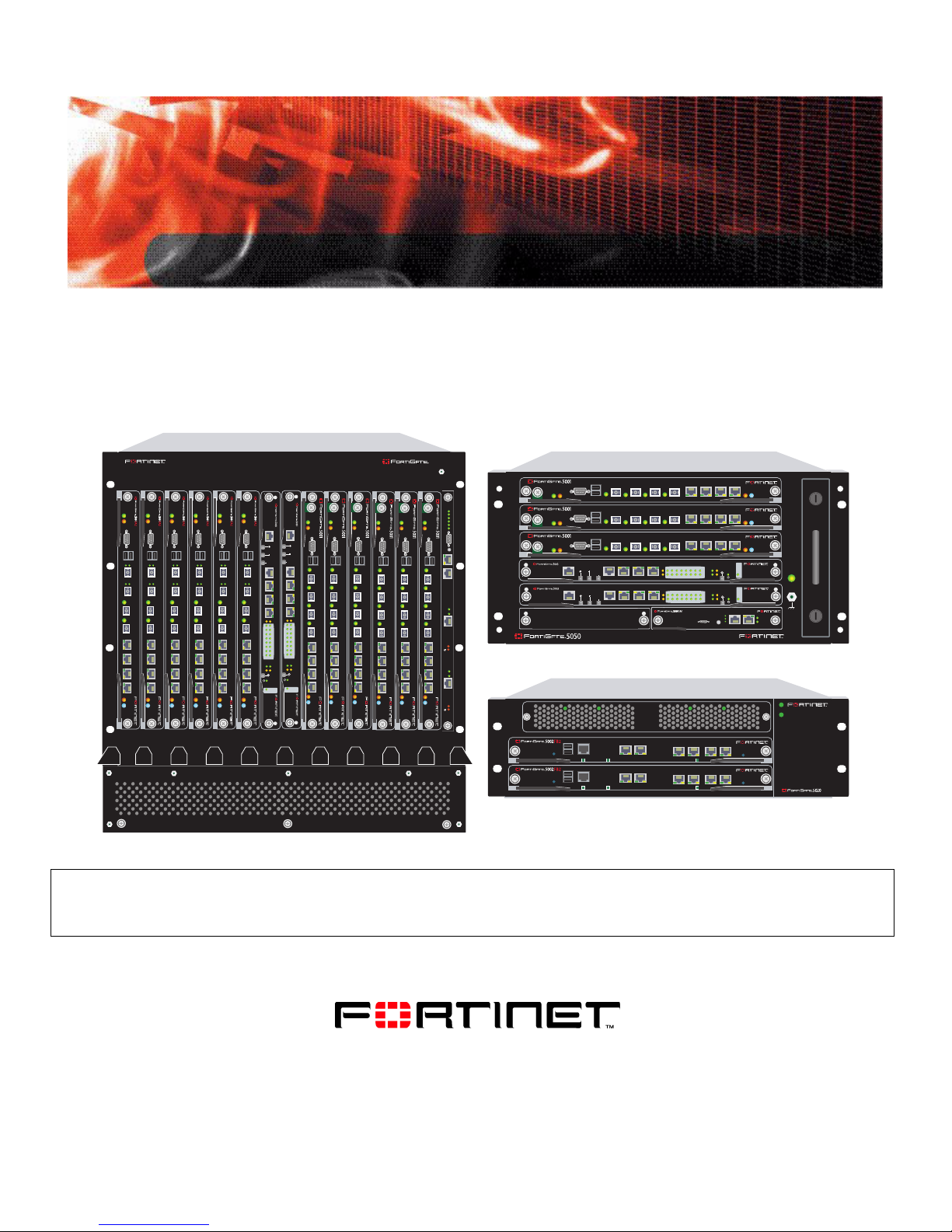
This FortiGate-5000 series Quick Guide is a high-level guide to all three
FortiGate-5000 series chassis and the FortiGate and FortiSwitch modules that
you can install in them. For detailed information about the FortiGate-5000 series
hardware, see the FortiGate-5000 Series Hardware Guide and the FortiGate-
5000 Installation Guide.
Fortinet documentation
The most up-to-date publications and previous releases of Fortinet product
documentation are available from the Fortinet Technical Documentation web site
at http://docs.forticare.com.
Fortinet Knowledge Center
Additional Fortinet technical documentation is available from the Fortinet
Knowledge Center. The knowledge center contains troubleshooting and how-to
articles, FAQs, technical notes, and more. Visit the Fortinet Knowledge Center at
http://kc.forticare.com.
Customer service and technical support
Fortinet Technical Support provides services designed to make sure that your
Fortinet systems install quickly, configure easily, and operate reliably in your
network.
Please visit the Fortinet Technical Support web site at http://support.fortinet.com
to learn about the technical support services that Fortinet provides.
FortiGate-5000 Series Quick Guide
01-00000-0294-20060315 5
Page 6

Customer service and technical support Introduction
FortiGate-5000 Series Quick Guide
6 01-00000-0294-20060315
Page 7
FortiGate-5140 chassis
FortiGate-5140 chassis
You can install up to 14 FortiGate-5000 series modules in the 14 slots of the
FortiGate-5140 ATCA chassis. The FortiGate-5140 is a 12U chassis that co ntains
two redundant hot swappable DC power entry modules that connect to -48 VDC
Data Center DC power. The FortiGate-5140 chassis also includes three hot
swappable cooling fan trays. If all 14 slots contain FortiGate-5001SX modules, the
FortiGate-5140 chassis provides a total of 112 Gigabit ethernet FortiGate
interfaces.
You can also install a FortiSwitch-5003 module in the FortiGate-5140 chassis to
provide HA heartbeat communications. You can add a second FortiSwitch-5003
module for redundancy. The First FortiSwitch-5003 module is installed in slot 1,
the second in slot 2.
The FortiGate-5140 chassis requires -48VDC Data Center DC power. If DC power
is not available you can install a FortiGate-5053 power converter tray (purchased
separately) with FortiGate-5140 power supplies.
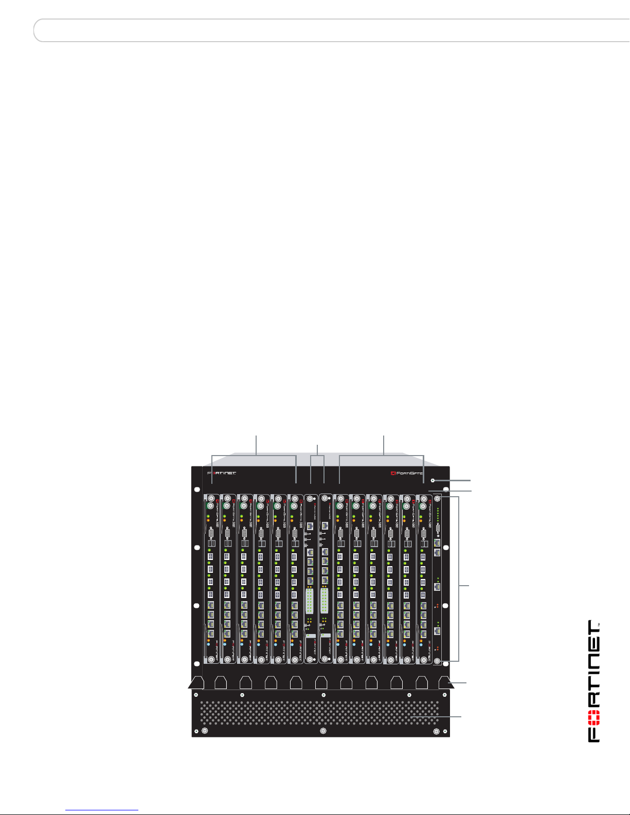
Figure 1 shows the front of a FortiGate-5140 chassis. Two FortiSwitch-5003
modules are installed in slots 1 and 2. Twelve FortiGate-5001SX modules are
installed in slots 3 to 14.
Figure 1: FortiGate-5140 chassis front panel
FortiGate-5001SX
modules
slots 3, 5, 7, 9,
11, and 13
FortiSwitch-5003
modules
FortiGate-5001SX
modules
slots 4, 6, 8, 10,
12, and 14
slots 1 and 2
13 11 9 7 5 3 1 2 4 6 8 10 12 14
PWRACC
PWRACC
PWRACC
CONSOLE
USB
1 2 3 4 5 6 7 8
STA IPM
STA IPM
PWRACC
CONSOLE
CONSOLE
USB
USB
1 2 3 4 5 6 7 8
1 2 3 4 5 6 7 8
STA IPM
STA IPM
PWRACC
PWRACC
MANAGEMENT
CONSOLE
CONSOLE
CONSOLE
USB
USB
USB
1 2 3 4 5 6 7 8
STA IPM
SYSTEM
CONSOLE
1 2 3 4 5 6 7 8
1 2 3 4 5 6 7 8
E2
ZRE
FLT
LED MODE
STA IPM
PWRACC
MANAGEMENT
E
E
T
T
H
H
O
O
SYSTEM
CONSOLE
R
R
S
S
2
2
3
3
2
2
Z
Z
R
R
E
E
0
0
Z
Z
R
R
E
E
1
1
Z
Z
R
R
E
E
2
2
E1
E2
E1
1514
1514
1312
1312
1110
1110
98
98
76
76
54
54
32
32
10
10
ZRE
OKCLK
OKCLK
INTEXT
INTEXT
FLT
FLT
FLT
HOT SWAP
HOT SWAP
RESET
RESET
LED MODE
STA IPM
PWRACC
PWRACC
CONSOLE
CONSOLE
USB
USB
1 2 3 4 5 6 7 8
1 2 3 4 5 6 7 8
STA IPM
STA IPM
PWRACC
PWRACC
CONSOLE
USB
1 2 3 4 5 6 7 8
CONSOLE
CONSOLE
USB
USB
1 2 3 4 5 6 7 8
1 2 3 4 5 6 7 8
STA IPM
STA IPM
PWRACC
STA IPM
5140
ESD socket
Slot
numbers
Crit.
Maj.
Min.
3
2
1
CONSOLE
Alarms
Rst
USB
1 2 3 4 5 6 7 8
Link
Act
100
ETH 0
Prim.
ShMC
Stat.
Link
Act
100
ETH 0
Sec.
ShMC
Stat.
FortiGate-5140
Shelf Manager
Front cable
3 hot-swappable
cooling fan trays
(numbered 0, 1, and
2 behind panel)
tray
FortiGate-5000 Series Quick Guide
01-00000-0294-20060315 7
Page 8
FortiGate-5140 chassis
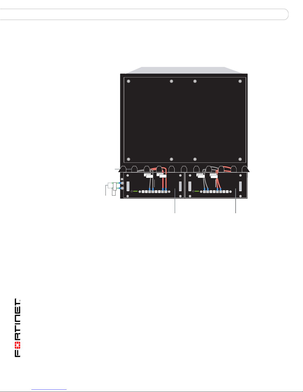
Figure 2 shows the back panel of the FortiGate-5140 chassis. The back panel
includes two hot-swappable redundant -48V/-60 VDC power entry modules
(PEMs) labelled PEM A and PEM B.
Figure 2: FortiGate-5140 chassis back panel
Back cable
tray
GND
Ground
connectors
(green)
GND
-48V
-48V
-48V/-60 VDC nom RTN
HS
HS
Alarm
operate
-48V/-60 VDC
nom (black)
BPEM PEM
RTN
RTN
RTN
(red)
12341234
12341234
HS
-48V/-60 VDC
nom (black)
RTN
-48V
-48V
RTN
-48V/-60 VDC nom RTN
HS
Alarm
operate
(red)
Power
Entry Module B
(protection
plate removed)
A
12341234
12341234
RTN
Power
Entry Module A
(protection
plate removed)
FortiGate-5000 Series Quick Guide
8 01-00000-0294-20060315
Page 9
FortiGate-5140 chassis Connecting a FortiGate-5140 chassis to Data Center DC power and Data Center ground
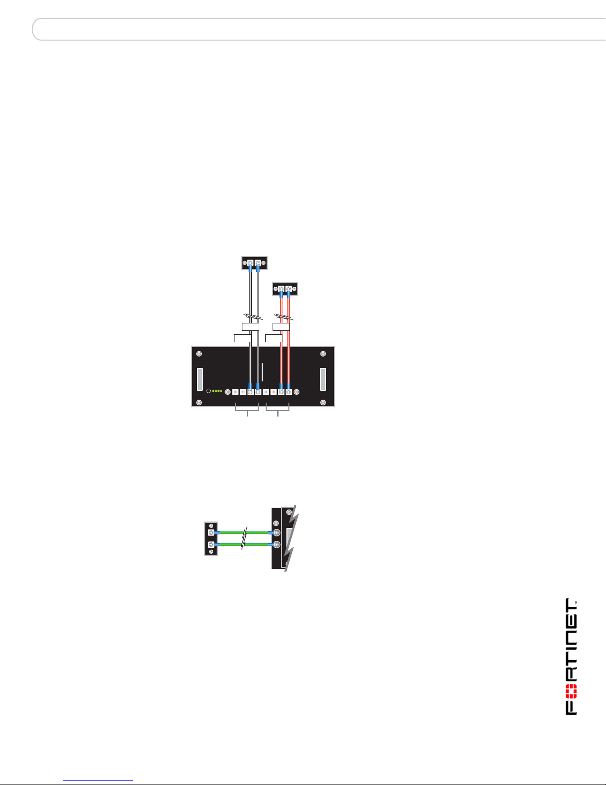
Connecting a FortiGate-5140 chassis to Data Center DC power
and Data Center ground
Connect the FortiGate-5140 chassis to Data Center DC power (also called battery
power) using the redundant power entry modules (PEMs). Fortinet supplies and
recommends AWG-14 stranded wires for all power connections. Black for
-48VDC, red for RTN, and green for ground. If required, install terminal lugs on the
wires before connecting them to the PEM terminal strips. If you are connecting
both PEMs the -48VDC and RTN terminals on PEM A and PEM B must be wired
symmetrically.
Figure 3: Connecting a FortiGate-5140 PEM to Data Center DC power
Data Center
-48VDC
connector
Data Center
RTN connector
-48V/-60 VDC
black to Data
Center -48VDC
-48V
-48V
RTN (positive)
RTN
RTN
red to Data
Center RTN
-48V/-60 VDC nom RTN
HS
HS
Alarm
operate
-48V/-60 VDC nom
terminal strip
connectors
1, 2, 3, 4
12341234
12341234
RTN (positive)
terminal strip
connectors
1, 2, 3, 4
Figure 4: Connecting a FortiGate-5140 chassis to Data Center ground
FortiGate-5140
Ground
connectors
Data Center
ground
connectors
FortiGate-5000 Series Quick Guide
01-00000-0294-20060315 9
Page 10

Connecting the FortiGate-5140 chassis to AC power using the FortiGate-5053 power converter tray FortiGate-5140 chassis
Connecting the FortiGate-5140 chassis to AC power using the
FortiGate-5053 power converter tray
If Data Center DC power is not available, you can use the FortiGate-5053 power
converter tray with FortiGate-5140 power supplies (shown in Figure 5) to convert
AC power to DC power. The FortiGate-5053 power converter tray and the power
supplies are not supplied with the FortiGate-5140 chassis and must be purchased
separately.
The front panel of the FortiGate-5053 power converter tray (shown in Figure 5)
provides access to the FortiGate-5140 power supplies.
Figure 5: Front panel of the FortiGate-5053 power converter tray with one power
supply removed
Slot 3
The back panel of the FortiGate-5053 (shown in Figure 6) includes one DC power
connector terminal consisting of a RTN connector and a -48VDC connector. The
-48VDC connector is labelled -V. The RTN connector is not labelled.
Figure 6: Back panel of the FortiGate-5053 power converter tray
Slot 2
Slot 1
24 VAC 1 2 3
V-
Positive
(RTN)
(red)
-48V/-58 VDC
V-
(black)
DC out
AC in
Selecting the power supplies and power convertor trays that you need for
your FortiGate-5140 configuration
The FortiGate-5053 power converter tray contains space for up to three
FortiGate-5140 power supplies. A FortiGate-5140 power supply converts AC
power to -48 VDC power. Each FortiGate-5140 power supply provides 1200W of
power.
The FortiGate-5053 power converter tray uses 2 + 1 power supply redundancy.
If three FortiGate-5140 power supplies are installed in a FortiGate-5053 power
converter tray, the first two power supplies provide a total of 2400W (2 x 1200W)
of power. The third power supply is the redundant backup.
FortiGate-5000 Series Quick Guide
10 01-00000-0294-20060315
Page 11
FortiGate-5140 chassis Connecting the FortiGate-5140 chassis to AC power using the FortiGate-5053 power converter tray
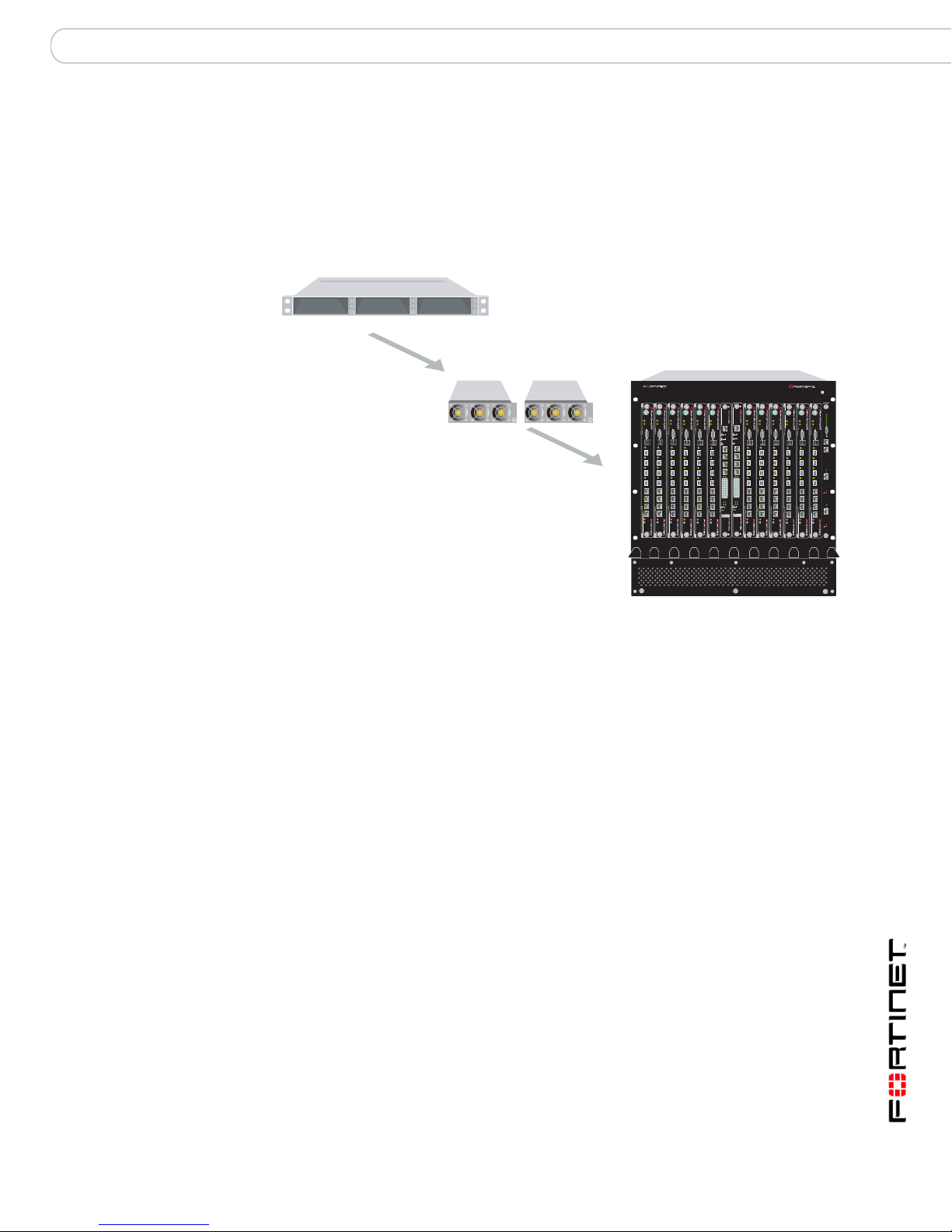
Basic power requirements
To supply enough power for a FortiGate-5140 ch assis with a total of 14 FortiGa t e
and FortiSwitch modules you require one FortiGate-5053 power converter tray
and two FortiGate-5140 power supplies (see Figure 7). The FortiGate-5140 power
supplies are installed in FortiGate-5053 slots 1 and 2. This configuration supplies
2400W of power to the FortiGate-5140 chassis.
Figure 7: Non-redundant power for all FortiGate-5140 chassis slots
1 FortiGate-5053
Slot 1Slot 2Slot 3
power convertor tray
2 FortiGate-5140
power supplies
2 x 1200W = 2400W
1 FortiGate-5140
chassis
13 11 9 7 5 3 1 2 4 6 8 10 12 14
PWRACC
PWRACC
PWRACC
CONSOLE
CONSOLE
USB
USB
1 2 3 4 5 6 7 8
1 2 3 4 5 6 7 8
STAIPM
STAIPM
PWRACC
PWRACC
PWRACC
MANAGEMENT
CONSOLE
CONSOLE
CONSOLE
CONSOLE
USB
USB
USB
USB
SYSTEM
CONSOLE
1 2 3 4 5 6 7 8
1 2 3 4 5 6 7 8
1 2 3 4 5 6 7 8
1 2 3 4 5 6 7 8
E1
E2
1514
1312
1110
98
76
54
32
10
ZRE
OKCLK
INTEXT
FLT
FLT
HOT SWAP
RESET
STAIPM
LED MODE
STAIPM
STAIPM
STAIPM
PWRACC
PWRACC
PWRACC
MANAGEMENT
E
E
T
T
H
H
O
O
CONSOLE
USB
SYSTEM
CONSOLE
R
R
S
S
2
2
3
3
2
2
1 2 3 4 5 6 7 8
Z
Z
R
R
E
E
0
0
Z
Z
R
R
E
E
1
1
Z
Z
R
R
E
E
2
2
E2
E1
1514
1312
1110
98
76
54
32
10
ZRE
OKCLK
INTEXT
FLT
FLT
HOT SWAP
RESET
LED MODE
STAIPM
PWRACC
PWRACC
CONSOLE
CONSOLE
CONSOLE
CONSOLE
USB
USB
USB
USB
1 2 3 4 5 6 7 8
1 2 3 4 5 6 7 8
1 2 3 4 5 6 7 8
1 2 3 4 5 6 7 8
STAIPM
STAIPM
STAIPM
STAIPM
For information about additional power configurations, see the FortiGate-5000
Series Hardware Guide.
5140
Crit.
Maj.
Min.
PWRACC
3
2
1
CONSOLE
Alarms
Rst
USB
1 2 3 4 5 6 7 8
Link
Act
100
ETH 0
Prim.
ShMC
Stat.
Link
Act
100
ETH 0
STAIPM
Sec.
ShMC
Stat.
FortiGate-5000 Series Quick Guide
01-00000-0294-20060315 11
Page 12
Connecting the FortiGate-5140 chassis to AC power using the FortiGate-5053 power converter tray FortiGate-5140 chassis
Connecting a FortiGate-5140 chassis to the FortiGate-5053 power converter
tray
To use a FortiGate-5053 power converter tray with the FortiGate-5140 chassis
you need to make DC power connections between the FortiGate-5140 chassis
and the FortiGate-5053 power converter tray. You also need to the connect the
FortiGate-5140 chassis to Data Center ground.
Figure 8: Connect a FortiGate-5140 PEM to a FortiGate-5053 power converter tray
24 VAC 1 2 3
V-
(RTN)
(Red)
V-
(Black)
-48V/-60 VDC Black to
FortiGate-5053
-48/-58 VDC
-48V
-48V/-60 VDC nom RTN
HS
HS
Alarm
operate
-48V/-60 VDC
terminal strip
connectors
1, 2, 3, 4
RTN Red to
FortiGate-5053
RTN
RTN
12341234
12341234
RTN (positive)
terminal strip
connectors
1, 2, 3, 4
AC in
FortiGate-5000 Series Quick Guide
12 01-00000-0294-20060315
Page 13

FortiGate-5050 chassis
FortiGate-5050 chassis
You can install up to five FortiGate-5000 series modules in the five slots of the
FortiGate-5050 ATCA chassis. The FortiGate-5050 is a 5U chassis that contains
two redundant DC power connections that connect to -48 VDC Data Center DC
power. The FortiGate-5050 chassis also includes a hot swappable cooling fan
tray. If all five slots contain FortiGate-5001SX modules, the FortiGate-5050
chassis provides a total of 40 Gigabit ethernet FortiGate interfaces.
You can also install a FortiSwitch-5003 module in the FortiGate-5050 chassis to
provide HA heartbeat communications. A single FortiSwitch-5003 module can
provide HA heartbeat communications for up to three FortiGate-5000 series
modules in the chassis. You can add a second FortiSwitch-5003 module for
redundancy. The first FortiSwitch-5003 module is installed in slot 2, the second in
slot 1.
The FortiGate-5050 chassis requires -48VDC Data Center DC power. If DC power
is not available you can install a FortiGate-5053 power converter tray (purchased
separately) with FortiGate-5020/5050 power supplies.
Figure 9 shows the front of a FortiGate-5050 chassis. Two FortiSwitch-5003
modules are installed in slots 1 and 2. Three FortiGate-5001SX modules are
installed in slots 3, 4, and 5.
Figure 9: FortiGate-5050 front panel
USB
1 2 3 4 5 6 7 8
FortiGate-5001SX
modules
slots 3, 4,
and 5
FortiSwitch-5003
modules
slots 1 and 2
CONSOLE
PWRACC
5
USB
1 2 3 4 5 6 7 8
4
3
2
1
ShMC
2
CONSOLE
PWRACC
USB
1 2 3 4 5 6 7 8
CONSOLE
PWRACC
ETH
O
MANAGEMENT
MANAGEMENT
ETH
O
RS232ZRE0ZRE1ZRE2
SYSTEM
CONSOLE
RS232ZRE0ZRE1ZRE2
SYSTEM
CONSOLE
E1
9876543210
1514
1312
1110
E2
E1
9876543210
1514
1312
1110
E2
FortiGate-5050
STA IPM
STA IPM
STA IPM
OKCLK
INTEXT
FLT
HOT SWAP
RESET
ZRE
FLT
OKCLK
INTEXT
FLT
HOT SWAP
RESET
ZRE
FLT
Critical
Major
Minor
Alarm
Alarm
Console Ethernet
Reset
POWER
LED MODE
LED MODE
ShMC
Hot Swap
Status
1
Hot-swappable
cooling fan tray
Power LED
ESD socket
Shelf Manager
The FortiGate-5050 chassis back panel includes two redundant - 48V to - 58V DC
power input connectors labelled Input A and Input B.
FortiGate-5000 Series Quick Guide
01-00000-0294-20060315 13
Page 14

Connecting the FortiGate-5050 chassis to Data Center DC power and Data Center ground FortiGate-5050 chassis
Figure 10: FortiGate-5050 chassis back panel
5
4
3
2
Ground
Connector
(green)
Power
fixture
wire
RTN
-48V
GND
Positive
1
(RTN)
(red)
INPUT A
DC VOLTAGE RANGE
-48V TO -58V
RTN (-DC IN)
-48V to -58V
(-DC in)
(black)
DC Power
Input A
25
AMP
RTN
-48V
Positive
(RTN)
(red)
INPUT B
DC VOLTAGE RANGE
-48V TO -58V
RTN (-DC IN)
-48V to -58V
(-DC in)
DC Power
Input B
(black)
25
AMP
ESD socket
Connecting the FortiGate-5050 chassis to Data Center DC power
and Data Center ground
Connect the FortiGate-5050 chassis to Data Center DC power (also ca lled battery
power) using the redundant power input connectors. Fortinet supplies and
recommends AWG-14 stranded wires for all power connections. Black for
-48VDC, red for RTN, and green for ground. If r equired, install terminal lugs on the
wires before connecting them to the power input connectors.
Figure 11: Connecting a FortiGate-5050 power input connector to Data Center DC
power
Data Center
Data Center
RTN connector
RTN (positive)
red to Data
Center RTN
Power wire
fixture
RTN
-48VDC
connector
-48V to -58V
-48V
(-DC in) black to
Data Center -48VDC
-48V TO -58V
RTN (-DC IN)
INPUT A
DC VOLTAGE RANGE
25
AMP
Positive
(RTN)
(-DC in)
(black)
(red)
FortiGate-5000 Series Quick Guide
14 01-00000-0294-20060315
-48V to -58V
Page 15

FortiGate-5050 chassis Connecting the FortiGate-5050 chassis to AC power using the FortiGate-5053 power converter tray
Figure 12: Connecting a FortiGate-5050 chassis to Data Center ground
Data Center
ground
connector
FortiGate-5050
Ground
connector
GND
Connecting the FortiGate-5050 chassis to AC power using the
FortiGate-5053 power converter tray
If Data Center DC power is not available, you can use the FortiGate-5053 power
converter tray with FortiGate-5020/5050 power supplies (shown in Figure13) to
convert AC power to DC power. The FortiGate-5053 power converter tray and the
power supplies are not supplied with the FortiGate-5050 chassis and must be
purchased separately. (FortiGate-5020/5050 power supplies are also used to
provide power to a FortiGate-5020 chassis.)
The front panel of the FortiGate-5053 power converter tray (shown in Figure 13)
provides access to the FortiGate-5020/5050 power supplies.
Figure 13: Front panel of the FortiGate-5053 power converter tray with on e power
supply removed
The back panel of the FortiGate-5053 (shown in Figure 14) includes one DC
power connector terminal consisting of a RTN connector and a -48VDC
connector. The -48VDC connector is labelled -V. The RTN connector is not
labelled.
Figure 14: Back panel of the FortiGate-5053 power converter tray
FortiGate-5000 Series Quick Guide
01-00000-0294-20060315 15
Slot 3
Positive
(RTN)
(red)
DC out
Slot 2
V-
V-
-48V/-58 VDC
(black)
Slot 1
24 VAC 1 2 3
AC in
Page 16

Connecting the FortiGate-5050 chassis to AC power using the FortiGate-5053 power converter tray FortiGate-5050 chassis
Selecting the power supplies and power convertor trays that you need for
your FortiGate-5050 configuration
The FortiGate-5053 power converter tray contains space for up to three
FortiGate-5020/5050 power supplies. A FortiGate-5020/5050 powe r supply
converts AC power to -48 VDC power. Each FortiGate-5020/5050 power supply
provides 800W of power.
The FortiGate-5053 power converter tray uses 2 + 1 power supply redundancy.
If three FortiGate-5020/5050 power supplies are installed in a FortiGate-5053
power converter tray, the first two power supplies provide a total of 1600W
(2 x 800W) of power. The third power supply is the redundant backup.
Basic power requirements
To supply enough power for a FortiGate-5050 chassis with a total of five Fort iGate
modules and FortiSwitch modules you require one FortiGate-5053 powe r
converter tray and two FortiGate-5020/5050 power supplies (see Figure 15). The
FortiGate-5020/5050 power supplies are inst alled in FortiGate-5053 slots 1 and 2.
This configuration supplies 1600W of power to the FortiGate-5020/5050 chassis.
Figure 15: Non-redundant power for all FortiGate-5050 chassis slots
1 FortiGate-5053
power convertor tray
Slot 1Slot 2Slot 3
2 FortiGate-5020/5050
power supplies
2 x 800W = 1600W
USB
1 2 3 4 5 6 7 8
1 FortiGate-5050
chassis
CONSOLE
PWRACC
5
4
3
2
1
ShMC
USB
1 2 3 4 5 6 7 8
CONSOLE
PWRACC
USB
1 2 3 4 5 6 7 8
CONSOLE
PWRACC
ETH
O
RS232ZRE0ZRE1ZRE2
E1
SYSTEM
CONSOLE
MANAGEMENT
ETH
O
MANAGEMENT
2
RS232ZRE0ZRE1ZRE2
SYSTEM
CONSOLE
E2
E1
E2
STAIPM
STAIPM
STAIPM
OKCLK
INTEXT
FLT
9876543210
1514
1312
1110
HOT SWAP
POWER
RESET
ZRE
LED MODE
FLT
OKCLK
INTEXT
FLT
9876543210
1514
1312
1110
HOT SWAP
RESET
ZRE
LED MODE
FLT
ShMC
Critical
Hot Swap
Major
Status
Minor
Alarm
Alarm
Console Ethernet
Reset
1
For information about additional power configurations, see the FortiGate-5000
Series Hardware Guide.
FortiGate-5000 Series Quick Guide
16 01-00000-0294-20060315
Page 17

FortiGate-5050 chassis Connecting the FortiGate-5050 chassis to AC power using the FortiGate-5053 power converter tray
Connecting a FortiGate-5050 chassis to the FortiGate-5053 power converter
tray
To use a FortiGate-5053 power converter tray with the FortiGate-5050 chassis
you need to make DC power connections between the FortiGate-5050 chassis
and the FortiGate-5053 power converter tray. You also need to the connect the
FortiGate-5050 chassis to Data Center ground.
Figure 16: Connecting a FortiGate-5050 power input connector to a FortiGate-5053
power converter tray
24 VAC 1 2 3
V-
(RTN)
(red)
RTN red to
FortiGate-5053
RTN
RTN
-48V
-48V/-58 VDC black to
V-
(black)
AC in
FortiGate-5053
-48/-58 VDC
Power wire
fixture
Positive (RTN) (red)
DC VOLTAGE RANGE
-48V TO -58V
RTN (-DC IN)
INPUT A
-48V/-58V
-DC in
(black)
25
AMP
FortiGate-5000 Series Quick Guide
01-00000-0294-20060315 17
Page 18

Connecting the FortiGate-5050 chassis to AC power using the FortiGate-5053 power converter tray FortiGate-5050 chassis
FortiGate-5000 Series Quick Guide
18 01-00000-0294-20060315
Page 19

FortiGate-5020 chassis
FortiGate-5020 chassis
You can install one or two FortiGate-5000 series modules in the two slots of the
FortiGate-5020 ATCA chassis. The FortiGate-5020 is a 4U chassis that contains
two redundant AC to DC power supplies that connect to AC power. The
FortiGate-5020 chassis also includes an internal cooling fan tray. If both slots
contain FortiGate-5001SX modules, the FortiGate-5020 chassis provides a total
of 16 Gigabit ethernet FortiGate interfaces.
If you install the same FortiGate-5000 series module in both slots, you can
configure the modules to operate as an HA cluster. HA heartbeat communications
between the modules uses the FortiGate-5020 backplane. No extra switching or
other connections are required.
The FortiGate-5020 chassis can only be connected to AC power. Two redundant
FortiGate-5020/5050 power supplies are factory installed in the FortiGate-5020
chassis.
Figure 17 shows the front of a FortiGate-5020 chassis. Two FortiGate-5001SX
modules are installed. The FortiGate-5020/5050 power supplies are factory
installed behind the panel at the top of the chassis. The power LEDs for the power
supplies are visible on the front panel as well.
Figure 17: FortiGate-5020 front panel with two FortiGate-5001SX modules
Hot-swappable
FortiGate-5020/5050
power supplies
(behind panel)
Power LEDs
PSU A PSU B
PSUA
PSU B
USB
1 2 3 4 5 6 7 8
USB
1 2 3 4 5 6 7 8
STA IPM
STA IPM
Hot swappable
cooling fan tray
FortiGate-5001SX
modules
PWRACC
PWRACC
CONSOLE
CONSOLE
(accessable from
back panel)
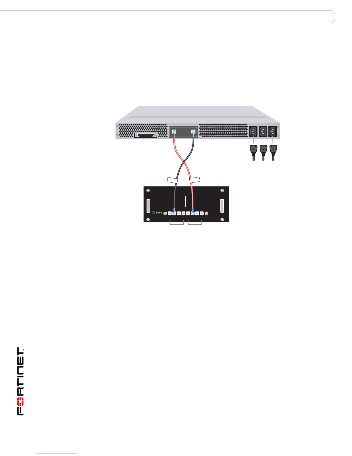
Figure 18 shows the back of a FortiGate-5020 chassis. The chassis back panel
includes two redundant AC power connectors and provides access to the hot
swappable cooling fan tray. Each AC power connector includes a 25 Amp circuit
breaker that also functions as the on/off switch for the AC power connector. You
can use the power wire fixtures to secure AC power wires to prevent the power
wires from being accidently disconnected.
FortiGate-5000 Series Quick Guide
01-00000-0294-20060315 19
Page 20

Connecting the FortiGate-5020 chassis to AC power FortiGate-5020 chassis
Figure 18: FortiGate-5020 chassis back panel
AC power
connector
Hot swappable
cooling fan tray
Power
wire
fixture
AC power
connector
Power
wire
fixture
Connecting the FortiGate-5020 chassis to AC power
The AC power connectors on the back of the FortiGate-5020 chassis provide
power to two factory installed redundant FortiGate-5020/5050 power supplies.
Each power supply distributes 800 W of 48VDC power to the entire
FortiGate-5020 chassis.
FortiGate-5000 Series Quick Guide
20 01-00000-0294-20060315
Page 21

FortiGate-5001SX security system
FortiGate-5001SX security system
The FortiGate-5001SX security system module is a high-performance FortiGate
security system with a total of 8 Gigabit ethernet interfaces. The
FortiGate-5001SX module supports high-end features including 802.1Q VLANs
and multiple virtual domains. You can also configure two or more
FortiGate-5001SX modules to create a high availability (HA) cluster to provide
failover protection and load balancing. HA clustering uses two internal gigabit
interfaces for HA communication through the FortiGate-5000 series chassis
backplane, leaving all eight front panel gigabit interfaces available for network
connections.
The FortiGate-5001SX module includes the following features:
• A total of eight gigabit interfaces
• Four gigabit interfaces that can accept Small Formfactor Pluggable (SFP)
fiber or copper transceivers (interfaces 1, 2, 3, and 4)
• Four 1000Base-T gigabit copper network interfaces (interfaces 5, 6, 7,
and 8)
• DB-9 RS-232 serial console connection
• USB connec tor
• Mounting hardware
• LED status indicators
The FortiGate-5001SX module comes supplied with four fiber or four copp er SFP
transceivers. Before you can connect FortiGate-5001SX interfaces 1 to 4, you
must insert the SPF transceivers into the FortiGate-5001SX front panel cage slots
numbered 1 to 4.
Figure 19: FortiGate-5001SX front panel
Module
PositionLink/Traffic
Status
STA IPM
Extraction
Lever
Mounting
Knot
Mounting
Knot
Locking
Power
Screw
Flash Disk
Access
ACC
PWR
Extraction
Lever
CONSOLE
RS-232
Serial
USB
USB
1 2 3 4 5 6 7 8
1 2 3 4
SFP Gigabit fiber
or copper
5 6 7 8
Gigabit Copper
Table 1 lists and describes the FortiGate-5001SX module LEDs.
Table 1: FortiGate-5001SX LEDs
LED State Description
PWR Green The FortiGate-5001SX module is powered on.
FortiGate-5000 Series Quick Guide
01-00000-0294-20060315 21
Page 22

Changing jumper settings FortiGate-5001SX security system
Table 1: FortiGate-5001SX LEDs (Continued)
LED State Description
ACC Off or
Flashing
red
STA Green Normal operation.
Red The FortiGate-5001SX is starting or a fault condition exists.
IPM Blue The FortiGate-5001SX is ready to be hot-swapped (removed
Flashing
Blue
Off Normal operation. The FortiGate-5001SX module is in contact
1, 2, 3, 4 Green The correct cable is connected to the gigabit SPF interface.
Flashing Network activity at the gigabit SPF interface.
5, 6, 7, 8 Green The correct cable is connected to the copper 1000Base-T
Flashing Network activity at this interface.
Amber The interface is connected at 1000 Mbps.
The ACC LED flashes red when the FortiGate-5001SX module
access the FortiOS flash disk.
from the chassis).
The FortiGate-5001SX is changing from hot swap to running
mode or from running mode to hot swap.
with the chassis backplane.
gigabit interface and the connected equipment has power.
Table 2 lists and describes the FortiGate-5001SX connectors.
Table 2: FortiGate-5001SX connec to rs
Connector Type Speed Protocol Description
1, 2, 3, 4 LC
SFP
5, 6, 7, 8 RJ-45 1000Base-T Ethernet Copper gigabit connection to
CONSOLE DB-9 9600 bps RS-232 serialSerial connection to the command line
USB USB USB key firmware updates and
Changing jumper settings
The JP3 jumper on the FortiGate-5001SX module is factory set by Fortinet into
one of two positions (see Figure 20 on page 23):
• For a FortiGate-5140 or FortiGate-5050 chassis, the jumper connects pins 2
and 3
• For a FortiGate-5020 chassis, the jumper connects pins 1 and 2
The jumper must connect pins 2 and 3 if the chassis contains a shelf manager.
Both the FortiGate-5140 and the FortiGate-5050 contain shelf managers, and the
FortiGate-5020 does not.
If the JP3 jumper settings are incorrect, when you insert the FortiGate-5001SX
module into a chassis the module may not start up or may not be able to
communicate with the chassis shelf manager.
1000Base-SX Ethernet Four gigabit SFP interfaces that can
accept fiber or copper gigabit
transceivers.
10/100/1000Base-T copper networks.
interface.
configuration backup (FortiOS v3.0).
FortiGate-5000 Series Quick Guide
22 01-00000-0294-20060315
Page 23

FortiGate-5001SX security system Inserting a FortiGate-5001SX module into a chassis
Normally, because the jumpers are factory set, you do not have to change them.
However, if you are moving a FortiGate-5001SX from a FortiGate-5140 or
FortiGate-5050 to a FortiGate-5020 or the reverse, you need to move the JP3
jumper.
Table 3: FortiGate-5001SX JP3 jumper settings for each chassis
Chassis Correct JP3
Result of wrong jumper setting
Jumper Setting
FortiGate-5140 pins 2 and 3 Shelf manager cannot find FortiGate-5001SX module.
No chassis information available
FortiGate-5050 pins 2 and 3 Shelf manager cannot find FortiGate-5001SX module.
No chassis information available
FortiGate-5020 pins 1 and 2 FortiGate-5001SX module will not start up.
Figure 20: FortiGate-5001SX jumper positions
Pins 2 and 3
5050 and 5140 chassis
Pins 1 and 2
JP3
5020 chassis
JP3
JP2
JP1
JP3
Inserting a FortiGate-5001SX module into a chassis
The FortiGate-5001SX module left extraction lever contacts to a hidden power
switch. The module must be fully installed in a chassis slot and this extraction
lever must be closed and locked for the FortiGate-5001SX module to receive
power and operate normally. If the FortiGate-5001SX module is not receiving
power, the IPM LED glows blue and all other LEDs remain off.
FortiGate-5000 Series Quick Guide
01-00000-0294-20060315 23
Front Faceplate
Page 24

Inserting a FortiGate-5001SX module into a chassis FortiGate-5001SX security system
Figure 21: FortiGate-5001SX module mounting components
Closed
Alignment Pin
Alignment Pin
Mounting
Knot
Locking
Screw
Left Extraction
Lever
Mounting Knot
Locking
Screw
Left Extraction
Lever
Open
Alignment Pin
Locking
Screw
Power
Mounting Knot
Left Extraction
Lever
Switch
Switch
Contact
Table 4: FortiGate-5001SX normal operating LEDs
LED State
PWR Green
ACC Off (Or flashing red when the system accesses the FortiGate-5001SX
flash disk.)
STA Green
IPM Off
FortiGate-5000 Series Quick Guide
24 01-00000-0294-20060315
Page 25

FortiGate-5001FA2 security system
FortiGate-5001FA2 security system
The FortiGate-5001FA2 security system module is a high-performance FortiGate
security system similar to the FortiGate-5001SX security system but with added
accelerated packet forwarding and policy enforcement for two of its eight Gigabit
ethernet interfaces. Accelerated packet forwarding and policy enforcement results
in accelerated small packet performance required for voice, video, and other
multimedia streaming applications.
The FortiGate-5001FA2 module includes the following features:
• A total of eight gigabit interfaces
• Two accelerated gigabit interfaces that can accept SFP fiber or copper
gigabit transceivers (interfaces 1 and 2)
• Two gigabit interfaces that can accept Small Formfactor Pluggable (SFP)
fiber or copper gigabit transceivers (interfaces 1 and 2)
• Four 1000Base-T gigabit copper network interfaces (interfaces 5, 6, 7, 8)
• DB-9 RS-232 serial console connection
• USB connec tor
• Mounting hardware
• LED status indicators
The FortiGate-5001FA2 module comes supplied with four fiber or four copper
SFP transceivers. Before you can connect FortiGate-5001FA2 interfaces 1 to 4,
you must insert the SPF transceivers into the FortiGate-5001FA2 front panel cage
slots numbered 1 to 4.
Figure 22: FortiGate-5001FA2 front panel
Mounting
Knot
Flash Disk
Access
Power
PWR
Extraction
Lever
ACC
CONSOLE
RS-232
Serial
USB
USB
Link/Traffic
1 2
1 2 SPF Gigabit
Fiber or Copper
Accelerated
3 4
3 4 SPF Gigabit
Fiber or Copper
5 6 7 8
5 6 7 8
Gigabit Copper
Status
Extraction
Table 5 lists and describes the FortiGate-5001FA2 module LEDs.
Table 5: FortiGate-5001FA2 module LEDs
LED State Description
PWR Green The FortiGate-50012FA2 module is powered on.
ACC Off or
Flashing
red
The ACC LED flashes red when the FortiGate-5001FA2
module access the FortiOS flash disk.
Module
Position
STA IPM
Lever
Mounting
Knot
FortiGate-5000 Series Quick Guide
01-00000-0294-20060315 25
Page 26

Changing jumper settings FortiGate-5001FA2 security system
Table 5: FortiGate-5001FA2 module LEDs
LED State Description
STA Green Normal operation.
Red The FortiGate-5001FA2 is booting or a fault condition exists.
IPM Blue The FortiGate-5001FA2 is ready to be hot-swapped (removed
Flashing
Blue
Off Normal operation. The FortiGate-5001FA2 module is in
1, 2, 3, 4 Green The correct cable is connected to the gigabit SPF interface.
Flashing Network activity at the gigabit SPF interface.
5, 6, 7, 8 Green The correct cable is connected to the copper 1000Base-T
Flashing Network activity at this interface.
Amber The interface is connected at 1000 Mbps.
from the chassis).
The FortiGate-5001FA2 is changing from hot swap to runni ng
mode or from running mode to hot swap.
contact with the chassis backplane.
gigabit interface and the connected equipment has power.
Table 6 lists and describes the FortiGate-5001FA2 connectors.
Table 6: FortiGate-5001FA2 connectors
Connector Type Speed Protocol Description
1 and 2 LC SFP 1000Base-SX Ethernet Two gigabit SFP interfaces that can
3 and 4 LC SFP 1000Base-SX Ethernet Two gigabit SFP interfaces that can
5, 6, 7, 8 RJ-45 1000Base-T Ethernet Copper gigabit connection to
CONSOLE DB-9 9600 bps RS-232
USB USB USB key firmware updates and
Changing jumper settings
The JP3 jumper on the FortiGate-5001FA2 module is factory set by Fortinet into
one of two positions (see Figure 23 on page 27):
• For a FortiGate-5140 or FortiGate-5050 chassis, the jumper connects pins 2
and 3
• For a FortiGate-5020 chassis, the jumper connects pins 1 and 2
The jumper must connect pins 2 and 3 if the chassis contains a shelf manager.
Both the FortiGate-5140 and the FortiGate-5050 contain shelf managers, and the
FortiGate-5020 does not.
serial
accept fiber or copper gigabit
transceivers.
accept fiber or copper gigabit
transceivers.
10/100/1000Base-T copper networks.
Serial connection to the command line
interface.
configuration backup (FortiOS v3.0).
If the JP3 jumper settings are incorrect, when you insert the FortiGate-5001FA2
module into a chassis the module may not start up or may not be able to
communicate with the chassis shelf manager.
FortiGate-5000 Series Quick Guide
26 01-00000-0294-20060315
Page 27

FortiGate-5001FA2 security system Changing jumper settings
Normally, because the jumpers are factory set, you do not have to change them.
However, if you are moving a FortiGate-5001FA2 from a FortiGate-5140 or
FortiGate-5050 to a FortiGate-5020 or the reverse, you need to move the JP3
jumper.
Also, if a new FortiGate-5001FA2 module does not function properly, you should
check the JP3 jumper settings.
Table 7: FortiGate-5001FA2 JP3 jumper settings for each chassis
Chassis Correct JP3
Result of wrong jumper setting
Jumper Setting
FortiGate-5140 pins 2 and 3 Shelf manager cannot find Forti Gate-5001FA2
module. No chassis information available
FortiGate-5050 pins 2 and 3 Shelf manager cannot find Forti Gate-5001FA2
module. No chassis information available
FortiGate-5020 pins 1 and 2 FortiGate-5001FA2 module will not start up.
Note: If the shelf manager in a FortiGate-5140 or FortiGate-5050 chassis is missing or not
functioning, FortiGate-5001FA2 modules with JP3 jumper connecting pins 2 and 3 will not
start up. To operate FortiGate-5001FA2 modules in a FortiGate-5140 or FortiGate-5050
chassis without a shelf manager, set the JP3 jumper to connect pins 1 and 2.
Figure 23: FortiGate-5001FA2 jumper positions
Pins 2 and 3
5050 and 5140 chassis
Pins 1 and 2
JP3
5020 chassis
JP3
JP2
FortiGate-5000 Series Quick Guide
01-00000-0294-20060315 27
JP1
JP3
Front Faceplate
Page 28

Inserting a FortiGate-5001FA2 module into a chassis FortiGate-5001FA2 security system
Inserting a FortiGate-5001FA2 module into a chassis
The FortiGate-5001FA2 module left extraction lever contacts to a hidden power
switch. The module must be fully installed in a chassis slot and this extraction
lever must be closed and locked for the FortiGate-5001FA2 module to receive
power and operate normally. If the FortiGate-5001FA2 module is not receiving
power, the IPM LED glows blue and all other LED s rem a in off .
Figure 24: FortiGate-5001FA2 module mounting components
Closed
Alignment Pin
Alignment Pin
Mounting
Knot
Extraction
Lever
Lock
Mounting
Knot
Extraction
Lever
Lock
Open
Left Extraction
Lever
Power
Switch
Lock
Switch Contact
Table 8: FortiGate-5001FA2 normal operating LEDs
LED State
PWR Green
ACC Off (Or flashing red when the system accesses the FortiGate-5001FA2
flash disk.)
STA Green
IPM Off
FortiGate-5000 Series Quick Guide
28 01-00000-0294-20060315
Page 29

FortiGate-5002FB2 security system
5
FortiGate-5002FB2 security system
The FortiGate-5002FB2 security system module is a high-performance FortiGate
security system with accelerated packet forwarding and policy enforcement for
two of its six Gigabit ethernet interfaces. Accelerated packet for warding and policy
enforcement results in accelerated small packet performance required for voice,
video, and other multimedia streaming applications.
The FortiGate-5002FB2 module supports high-end featur es including 802.1Q
VLANs and multiple virtual domains. You can also configure two or more
FortiGate-5002FB2 modules to create a high availability (HA) cluster to provide
failover protection and load balancing. HA clustering uses two internal gigabit
interfaces for HA communication through the FortiGate-5000 series chassis
backplane, leaving all eight front panel gigabit interfaces available for network
connections.
The FortiGate-5002FB2 module includes the following features:
• A total of six gigabit interfaces
• Two accelerated 1000Base-T gigabit copper network interfaces (interfaces
1 and 2)
• Four 1000Base-T gigabit copper network interfaces (interfaces 3, 4, 5, and
6)
• RJ-45 RS-232 serial console connection
• USB connec tor
• Mounting hardware
• LED status indicators
Figure 25: FortiGate-5002FB2 front panel
Alt On/Off
Mounting
ALT
ON/OFF
Extraction
Lever
Knot
Mounting
Knot
Extraction
Lever
RESET
Reset
RJ-45 Serial
USB
CONSOLE
STATUS
USB
Status
Power
162
PWR
1 2 Gigabit
Copper Accelerated
Module Position
3 4 5 6
IPM
3 4 5 6
Gigabit Copper
Table 9 lists and describes the FortiGate-5002FB2 module LEDs.
FortiGate-5000 Series Quick Guide
01-00000-0294-20060315 29
Page 30

FortiGate-5002FB2 security system
Table 9: FortiGate-5002FB2 module LEDs
LED State Description
STATUS Green Normal operation.
Red The FortiGate-5002FB2 is booting or a fault condition exists.
PWR Green The FortiGate-5002FB2 module is powered on.
IPM Blue The FortiGate-5002FB2 is ready to be hot-swapped (or card is
ready to be removed from the chassis).
Flashing
Blue
The FortiGate-5002FB2 is changing from hot swap to runni ng
mode or from running mode to hot swap.
Off Normal operation. The FortiGate-5002FB2 module is in
contact with the FortiGate chassis backplane.
Ports 1-6 Green The correct cable is connected to the copper 1000Base-T
gigabit interface and the connected equipment has power.
Flashing Network activity at this interface.
Amber The interface is connected at 1000 Mbps.
Table 10 lists and describes the FortiGate-5002FB2 connectors.
Table 10: FortiGate-5002FB2 connectors
Connector Type Speed Protocol Description
1, 2 RJ-45 1000Base-T Ethernet Copper gigabit connections to
10/100/1000Base-T copper networks.
3, 4, 5, 6 RJ-45 1000Base-T Ethernet Copper gigabit connection to
10/100/1000Base-T copper networks.
CONSOLE RJ-45 9600 bps RS-232
serial
Serial connection to the command line
interface.
USB USB USB key firmware updates and
configuration backup (FortiOS v3.0).
FortiGate-5000 Series Quick Guide
30 01-00000-0294-20060315
Page 31

FortiGate-5002FB2 security system Inserting a FortiGate-5002FB2 module into a chassis
Inserting a FortiGate-5002FB2 module into a chassis
The FortiGate-5002FB2 module left extraction lever contacts to a hidden power
switch. The module must be fully installed in a chassis slot and this extraction
lever must be closed and locked for the FortiGate-5002FB2 module to receive
power and operate normally. If the FortiGate-5002FB2 module is not receiving
power, the IPM LED glows blue and all other LEDs remain off.
Figure 26: FortiGate-5002FB2 module mounting components
Closed
Alignment Pin
Mounting
Knot
Extraction
Lever
Extraction Lever
Lock
Open
Alignment Pin
Mounting
Knot
Extraction
Lever
Extraction Lever
Switch
Contact
Power
Switch
Lock
Table 11: FortiGate-5002FB2 normal operating LEDs
LED State
STATUS Green
PWR Green
IPM Off
FortiGate-5000 Series Quick Guide
01-00000-0294-20060315 31
Page 32

Inserting a FortiGate-5002FB2 module into a chassis FortiGate-5002FB2 security system
FortiGate-5000 Series Quick Guide
32 01-00000-0294-20060315
Page 33

FortiSwitch-5003 module
FortiSwitch-5003 module
The FortiSwitch-5003 module provides switching for the FortiGate-5140 chassis
and the FortiGate-5050 chassis. This switching takes the form of backplane HA
heartbeat connections between FortiGate-5000 series modules installed in a
FortiGate-5140 chassis or a FortiGate-5050 chassis.
You can install a second FortiSwitch-5003 module in a FortiGate-5140 or
FortiGate-5050 chassis as a backup or redundant switch. In this configuration, if
one of the FortiSwitch-5003 modules fails, or is removed from the chassis, HA
heartbeat communication is not interrupted.
The FortiSwitch-5003 module includes the following features:
• A total of 16 1000Base-T gigabit ethernet interfaces:
• 13 backplane 1000Base-T gigabit interfaces for HA switching between
FortiGate-5000 series modules installed in the same chassis as the
FortiSwitch-5003
• Three front panel 1000Base-T gigabit interfaces for HA switching between
FortiGate-5000 series chassis
• One 100Base-TX out of band management ethernet interface
• RJ-45 RS-232 serial console connection
• Mounting hardware
• LED status indicators
Figure 27: FortiSwitch-5003 front panel
Out of Band Managemnt
Mounting
Knot
100Base-TX
Ethernet
MANAGEMENT
Extraction
Lever
ETH
O
RJ-45
Serial
RS232ZRE0ZRE1ZRE2
SYSTEM
CONSOLE
1000Base-T
Ethernet
Network
Activity LEDs
E1
9876543210
1514
1312
1110
E2
ZRE
LED Mode
OKCLK
INTEXT
FLT
HOT SWAP
FLT
Reset
Table 12 lists and describes the FortiSwitch-5003 module LEDs.
Table 12: FortiSwitch-5003 module LEDs
LED State Description
+ Green The FortiSwitch-5003 module is powered on.
+
System
Console
Yellow Caution status. Caution status is indicated by the fault condition
Yellow Out of service. Normally off. The LED is on when there is a
Green Normal operation.
of the CLOCK, OK or INT FLT LEDs.
switch failure.
RESET
LED MODE
Extraction
Lever
Mounting
Knot
FortiGate-5000 Series Quick Guide
01-00000-0294-20060315 33
Page 34

FortiSwitch-5003 module
Table 12: FortiSwitch-5003 module LEDs (Continued)
LED State Description
Yellow Link/Activity mode - Port is not forwarding packets.
Network
activity
LEDs
0-15
Green Link/Activity mode - Blinking LED indicates network traffic.
Off Link/Activity mode - No link.
Link/Speed mode - Indicates 1000 Mbps connection
Link/Speed mode - Indicates 100 Mbps connection.
Link/Speed mode - Indicates 10 Mbps connection.
Yellow Link/Activity mode - Port is not forwarding packets.
Link/Speed mode - Indicates 1000 Mbps connection
E1
Green Link/Activity mode - Blinking LED indicates network traffic.
Link/Speed mode - Indicates 100 Mbps connection.
Off Link/Activity mode - No link.
Link/Speed mode - Indicates 10 Mbps connection.
Yellow Link/Activity mode - Port is not forwarding packets.
Link/Speed mode - Indicates 1000 Mbps connection
E0
Green Link/Activity mode - Blinking LED indicates network traffic.
Link/Speed mode - Indicates 100 Mbps connection.
Off Link/Activity mode - No link.
Link/Speed mode - Indicates 10 Mbps connection.
OK Green Initialization completed successfully.
EXT FLT Yellow Cannot establish a link to a configured port or another
connection problem external to the adaptor.
INT FLT Yellow Failure of internal tests. Off during power up.
Hot Swap Blue Light on indicate s the switch is ready to remove. During a hot
swap, LED is on. LED turns off when the switch is correctly
installed.
Reset Press and hold Reset for three seconds to restart the switch.
LED Mode Change the port LED display function from Link/Activity mode
to Link/Speed mode.
Table 13 lists and describes the FortiSwitch-5003 connectors.
Table 13: FortiGate-5003 connectors
Connector Type Speed Protocol Description
ETH0 RJ-45 100Base-T Ethernet Ethernet out of band management
CONSOLE RJ-45 9600 bps RS-232
serial
ZRE0,
RJ-45 1000Base-T Ethernet Redundant connections to another
ZRE1,
ZRE2
34 01-00000-0294-20060315
connection.
Serial connection to the command line
interface.
FortiGate chassis.
FortiGate-5000 Series Quick Guide
Page 35

FortiSwitch-5003 module Inserting a FortiSwitch-5003 module into a chassis
Inserting a FortiSwitch-5003 module into a chassis
The FortiSwitch-5003 module left extraction lever contacts to a hidden power
switch. The module must be fully installed in a chassis slot and this extraction
lever must be closed and locked for the FortiSwitch-500 3 module to receive power
and operate normally. If the FortiSwitch-5003 module is not receiving power, the
Hot Swap LED glows blue and all other LEDs remain off.
Figure 28: FortiSwitch-5003 module mounting compone nts
Closed
Alignment Pin
Mounting
Knot
Extraction
Lever
Open
Alignment Pin
Mounting
Knot
Extraction
Lever
Table 14: FortiSwitch-5003 normal operating LEDs
LED State
+ Green
+
System
Console
Network
activity LEDs
0-15
OK Green
Off
Green
Off unless FortiGate-5000 series modules are operating in HA mode.
Switch
Contact
Power
Switch
FortiGate-5000 Series Quick Guide
01-00000-0294-20060315 35
Page 36

Inserting a FortiSwitch-5003 module into a chassis FortiSwitch-5003 module
FortiGate-5000 Series Quick Guide
36 01-00000-0294-20060315
Page 37

www.fortinet.com
 Loading...