

Fortinet Fortigate-3600A, Fortigate-3000, Fortigate-800, Fortigate-1000, Fortigate-500A Administration Manual
...Page 1

ADMINISTRATION GUIDE
FortiGate™
Version 3.0 MR4
www.fortinet.com
Page 2

FortiGate™ Administration Guide
Version 3.0 MR4
2 January 2007
01-30004-0203-20070102
© Copyright 2007 Fortinet, Inc. All rights reserved. No part of this
publication including text, examples, diagrams or illustrations may be
reproduced, transmitted, or translated in any form or by any means,
electronic, mechanical, manual, optical or otherwise, for any purpose,
without prior written permission of Fortinet, Inc.
Trademarks
Dynamic Threat Prevention System (DTPS), APSecure, FortiASIC,
FortiBIOS, FortiBridge, FortiClient, FortiGate, FortiGate Unified Threat
Management System, FortiGuard, FortiGuard-Antispam, FortiGuardAntivirus, FortiGuard-Intrusion, FortiGuard-Web, FortiLog, FortiAnalyzer,
FortiManager, Fortinet, FortiOS, FortiPartner, FortiProtect, FortiReporter,
FortiResponse, FortiShield, FortiVoIP, and FortiWiFi are trademarks of
Fortinet, Inc. in the United States and/or other countries. The names of
actual companies and products mentione d herein may be the trade marks
of their respective owners.
Page 3

Contents
Contents
Introduction...................................................................................... 17
Introducing the FortiGate units...................................................................... 18
FortiGate-5000 series chassis .................................................................... 18
About the FortiGate-5000 series modules .................................................. 19
FortiGate-3600A.......................................................................................... 19
FortiGate-3600............................................................................................ 20
FortiGate-3000............................................................................................ 20
FortiGate-1000A.......................................................................................... 20
FortiGate-1000AFA2................................................................................... 21
FortiGate-1000............................................................................................ 21
FortiGate-800.............................................................................................. 21
FortiGate-800F............................................................................................ 21
FortiGate-500A............................................................................................ 22
FortiGate-500.............................................................................................. 22
FortiGate-400A............................................................................................ 22
FortiGate-400.............................................................................................. 22
FortiGate-300A............................................................................................ 22
FortiGate-300.............................................................................................. 23
FortiGate-200A............................................................................................ 23
FortiGate-200.............................................................................................. 23
FortiGate-100A............................................................................................ 23
FortiGate-100.............................................................................................. 23
FortiGate-60/60M/ADSL.............................................................................. 24
FortiWiFi-60/60A/60AM............................................................................... 24
FortiGate-50B.............................................................................................. 24
FortiGate-50A.............................................................................................. 24
Fortinet family of products............................................................................. 25
FortiGuard Subscription Services ............................................................... 25
FortiAnalyzer............................................................................................... 25
FortiClient.................................................................................................... 25
FortiManager............................................................................................... 26
FortiBridge................................................................................................... 26
FortiMail ...................................................................................................... 26
FortiReporter............................................................................................... 26
About this document....................................................................................... 27
Document conventions................................................................................ 29
FortiGate documentation ............................................................................... 29
Fortinet Tools and Documentation CD........................................................ 31
Fortinet Knowledge Center ........................................................................ 31
Comments on Fortinet technical documentation ................................ ........ 31
Customer service and technical support...................................................... 31
FortiGate Version 3 .0 MR4 Administration Guide
01-30004-0203-20070102 3
Page 4

Contents
Web-based manager........................................................................ 33
Button bar features ......................................................................................... 34
Contact Customer Support ......................................................................... 34
Using the Online Help................................................................................. 34
Logout......................................................................................................... 36
Web-based manager pages............................................................................ 37
Web-based manager menu ........................................................................ 37
Lists............................................................................................................. 38
Icons ........................................................................................................... 38
System Status.................................................................................. 41
Status page.............. ... .... ... ... ... .... ... ... ... .... ....................................................... 41
Viewing system status ................................................................................ 41
Changing system information........................................................................ 49
Configuring system time ............................................................................. 49
Changing the FortiGate unit host name...................................................... 50
Changing the FortiGate firmware.................. ... ... .... ... ... ... .... ... ... ... ... .... ... ... ... . 51
Upgrading to a new firmware version ......................................................... 51
Reverting to a previous firmware version.................................................... 51
Viewing operational history............................................................................ 52
Manually updating FortiGuard definitions.................................................... 53
Viewing Statistics............................................................................................ 54
Viewing the session list.............................................................. ... .... ... ... ... . 54
Viewing the Content Archive information.................................................... 55
Viewing the Attack Log ............................................................................... 56
Topology viewer.............................................................................................. 58
The Topology Viewer window.............................. ... ... ... .... ... ... ... ... .... ... ... ... . 58
Customizing the topology diagram.............................................................. 60
........................................................................................................................... 60
Using virtual domains ..................................................................... 61
Virtual domains................................................................................................ 61
VDOM configuration settings ...................................................................... 62
Global configuration settings....................................................................... 63
Enabling VDOMs.............................................................................................. 64
Configuring VDOMs and global settings............................. ... ... ... ... .... ... ... ... . 64
Working with VDOMs and global settings................................................... 65
Adding interfaces to a VDOM ..................................................................... 65
Assigning an administrator to a VDOM....................................................... 66
Changing the Management VDOM...................................................... ... ... . 67
FortiGate Version 3 .0 MR4 Administration Guide
4 01-30004-0203-20070102
Page 5

Contents
System Network............................................................................... 69
Interface............................................................................................................ 69
Switch Mode........... ... ... .... ... ... ..................................................................... 71
Interface settings......................................................................................... 72
Configuring an ADSL interface.................................................................... 74
Creating an 802.3ad aggregate interface.................................................... 75
Creating a redundant interface............ ........................................................ 76
Creating a wireless interface....................................................................... 77
Configuring DHCP on an interface.............................................................. 78
Configuring an interface for PPPoE or PPPoA ........................................... 80
Configuring Dynamic DNS service for an interface..................................... 81
Configuring a virtual IPSec interface........................................................... 82
Additional configuration for interfaces......................................................... 83
Zone.................................................................................................................. 87
Zone settings............................................................................................... 87
Network Options.............................................................................................. 88
DNS Servers ............................................................................................... 89
Dead gateway detection.............................................................................. 89
Routing table (Transparent Mode)................................................................. 90
Transparent mode route settings ................................................................ 90
Configuring the modem interface.................................................................. 91
Configuring modem settings ....................................................................... 91
Redundant mode configuration................................................................... 93
Standalone mode configuration .................................................................. 94
Adding firewall policies for modem connections ......................................... 94
Connecting and disconnecting the modem............................. ... ... ... ... .... ... . 95
Checking modem status.............................................................................. 95
VLAN overview............................... .... ... ... ... .... ... ... ... ........................................ 96
FortiGate units and VLANs . ... ... .... ... ... ... .... ... .............................................. 96
VLANs in NAT/Route mode............................ ... ... ... ........................................ 97
Rules for VLAN IDs..................................................................................... 97
Rules for VLAN IP addresses ..................................................................... 97
Adding VLAN subinterfaces ........................................................................ 98
VLANs in Transparent mode .......................................................................... 99
Rules for VLAN IDs................................................................................... 101
Transparent mode virtual domains and VLANs ......... ... ... ... .... ... ... ... ... .... .. 101
Troubleshooting ARP Issues..................................................................... 104
FortiGate IPv6 support.................................................................................. 104
System Wireless............................................................................. 105
The FortiWiFi wireless LAN interface.......................................................... 105
Channel assignments.................................................................................... 106
System wireless settings (FortiWiFi-60)...................................................... 107
FortiGate Version 3 .0 MR4 Administration Guide
01-30004-0203-20070102 5
Page 6

Contents
System wireless settings (FortiWiFi-60A and 60AM)................................. 109
Wireless MAC Filter....................................................................................... 110
Wireless Monitor............................................................................................ 111
System DHCP................................................................................. 113
FortiGate DHCP servers and relays............................................................. 113
Configuring DHCP services........................... ... ... .... ..................................... 114
Configuring an interface as a DHCP relay agent...................................... 115
Configuring a DHCP server ...................................................................... 115
Viewing address leases................................................................................ 116
Reserving IP addresses for specific clients .................. .... ... ..................... 117
System Config................................................................................ 119
HA .......................... ... ... .... .......................................................................... ... .. 119
HA options ................................................................................................ 119
Cluster members list ..................................... ... ......................................... 122
Viewing HA statistics........... .... ... ... ... .... ... ... ... ... ......................................... 125
Changing subordinate unit host name and device priority........................ 126
Disconnecting a cluster unit from a cluster............................................. .. 126
SNMP........... .... ... ... ... ... .... ... ... ... ...................................................................... 127
Configuring SNMP .................................................................................... 127
Configuring an SNMP community............................................................. 128
Fortinet MIBs............................................................................................. 130
FortiGate traps.......................................................................................... 131
Fortinet MIB fields..................................................................................... 133
Replacement messages . ... ... ... .... ... ... ............................................................ 136
Replacement messages list...................................................................... 137
Changing replacement messages ....... ... .................................................. 138
Changing the authentication login page.................. ... ... .... ... ... ... ... ............ 139
Changing the FortiGuard web filtering block override page...................... 140
Changing the SSL-VPN login message.................. ... ............................... 140
Changing the authentication disclaimer page............................... .... ... ... .. 140
Operation mode and VDOM management access................. ... ... ... .... ... ... .. 141
Changing operation mode............. ... .... ... ... ... ... .... ... ... ... .... ... ..................... 141
Management access................................................................................. 142
System Admin................................................................................ 143
Administrators................................... ... .... ... ... ... ............................................ 143
Configuring RADIUS authentication for administrators............................. 144
Viewing the administrators list ...................................... .... ... ... ... ... .... ... ..... 144
Configuring an administrator account....................................................... 146
Access profiles.............................................................................................. 148
Viewing the access profiles list ........................ .... ... ... ... .... ... ... ... ............... 151
Configuring an access profile..... ... ... ......................................................... 152
FortiGate Version 3 .0 MR4 Administration Guide
6 01-30004-0203-20070102
Page 7

Contents
FortiManager.................................................................................................. 153
Settings........................................................................................................... 153
Monitoring administrators ................................................ ... ... .... ... ... ... ... ...... 154
System Maintenance...................................................................... 157
Backup and restore....................................................................................... 157
FortiGuard Center.......................................................................................... 161
FortiGuard Distribution Network................................................................ 161
FortiGuard Services .................................................................................. 161
Configuring the FortiGate unit for FDN and FortiGuard services.............. 162
Troubleshooting FDN connectivity ............................................................ 166
Updating antivirus and attack definitions................................................... 166
Enabling push updates.............................................................................. 168
License ........................................................................................................... 172
System Chassis (FortiGate-5000 series)...................................... 173
SMC (shelf manager card) ............................................................................ 173
Blades (FortiGate-5000 chassis slots)......................................................... 174
Chassis monitoring event log messages.................................................... 176
Router Static .................................................................................. 177
Routing concepts ......................................................................................... 177
How the routing table is built .................................................................... 178
How routing decisions are made .............................................................. 178
Multipath routing and determining the best route...................................... 178
How route sequence affects route priority ................................................ 179
Equal Cost Multipath (ECMP) Routes....................................................... 180
Static Route ...... .... ............................................................................. ... ... .... .. 180
Working with static routes .................................. ... .... ... ... ... ...................... 180
Default route and default gateway ........................................................... 181
Adding a static route to the routing table ............................ ....... ... ... ... .... .. 184
Policy Route .................................................................................................. 185
Adding a route policy ............. ... .... ............................................................ 186
Moving a route policy ................................................................................ 187
Router Dynamic.............................................................................. 189
RIP................................................................................................................... 189
How RIP works.......................................................................................... 190
Viewing and editing basic RIP settings..................................................... 190
Selecting advanced RIP options ............................................................... 192
Overriding the RIP operating parameters on an interface......................... 193
FortiGate Version 3 .0 MR4 Administration Guide
01-30004-0203-20070102 7
Page 8

Contents
OSPF ... ... ... .......................................................................... .... ... ... ... ... ............ 194
OSPF autonomous systems ..................................................................... 194
Defining an OSPF AS ............................................................................... 195
Viewing and editing basic OSPF settings ................................................. 196
Selecting advanced OSPF options ................................... ... ... .................. 198
Defining OSPF areas................. ... ............................................................ 199
Specifying OSPF networks ....................................................................... 200
Selecting operating parameters for an OSPF interface ............................ 201
BGP . .... ... .......................................................................... ... ............................ 202
How BGP works........................................................................................ 202
Viewing and editing BGP settings............................................................. 203
Multicast......................................................................................................... 204
Viewing and editing multicast settings ...................................................... 204
Overriding the multicast settings on an interface...................................... 206
Router Monitor............................................................................... 209
Displaying routing information.................................................................... 209
Searching the FortiGate routing table.......................................... ... .... ........ 211
Firewall Policy................................................................................ 213
About firewall policies ...................... ... .... ... ... ... ... .... ... ... ............................... 213
How policy matching works....................................................................... 214
Viewing the firewall policy list...................................................................... 214
Adding a firewall policy ............................................................................. 215
Moving a policy to a different position in the policy list ............................. 216
Configuring firewall policies ........................................................................ 216
Firewall policy options.......................................................... ... ... ... .... ... ... .. 219
Adding authentication to firewall policies ...................... .... ... ... ... ... .... ... ..... 222
Adding traffic shaping to firewall policies .................................................. 223
IPSec firewall policy options ................ ... ... ............................................... 226
SSL-VPN firewall policy options................................................................ 226
Options to check FortiClient on hosts ..................... ... ... .... ... ... ... ............... 227
Firewall policy examples .............................................................................. 228
Scenario one: SOHO sized business...... ... ... ... .... ... ... ... .... ... ... ... ... .... ... ... .. 228
Scenario two: enterprise sized business................................................... 231
Firewall Address............................................................................ 235
About firewall addresses......................................... ... .................................. 235
Viewing the firewall address list .................................................................. 236
Configuring addresses ........................ .... ... ... ... ... .... ... ... ... .... ... ... ... ... .... ... ..... 237
Viewing the address group list ............................... ... ... ... .... ... ... ... ... .... ... ... .. 237
Configuring address groups........................................................................ 238
FortiGate Version 3 .0 MR4 Administration Guide
8 01-30004-0203-20070102
Page 9

Contents
Firewall Service.............................................................................. 239
Viewing the predefined service list.............................................................. 239
Viewing the custom service list ................................................................... 243
Configuring custom services....................................................................... 243
Viewing the service group list...................................................................... 245
Configuring service groups.......................................................................... 245
Firewall Schedule........................................................................... 247
Viewing the one-time schedule list.............................................................. 247
Configuring one-time schedules.................................................................. 248
Viewing the recurring schedule list ............................................................. 248
Configuring recurring schedules................................................................. 249
Firewall Virtual IP........................................................................... 251
Virtual IPs.......... .... ... ... ... ... .... ......................................................................... 251
How virtual IPs map connections through the FortiGate unit.................... 251
Viewing the virtual IP list .............................................................................. 255
Configuring virtual IPs.................................................................................. 255
Adding a static NAT virtual IP for a single IP address............................... 256
Adding a static NAT virtual IP for an IP address range............................. 258
Adding static NAT port forwarding for a single IP address and a
single port.................................................................................................. 260
Adding static NAT port forwarding for an IP address range and a
port range.................................................................................................. 261
Adding a load balance virtual IP for an IP address range or real servers. 263
Adding a load balance port forwarding virtual IP....................................... 265
Adding dynamic virtual IPs........................................................................ 266
Virtual IP Groups ........................................................................................... 267
Viewing the VIP group list............................................................................. 267
Configuring VIP groups ................................................................................ 268
IP pools. .... ... .......................................................................... ... .... ... ... ... ......... 269
IP pools and dynamic NAT........................................................................ 269
IP Pools for firewall policies that use fixed ports....................................... 269
Viewing the IP pool list................................... ... ... ......................................... 270
Configuring IP Pools..................................................................................... 270
Firewall Protection Profile............................................................. 271
What is a protection profile .......................................................................... 271
Default protection profiles ......................................................................... 272
Viewing the protection profile list................................................................ 272
FortiGate Version 3 .0 MR4 Administration Guide
01-30004-0203-20070102 9
Page 10

Contents
Configuring a protection profile................................................................... 272
Antivirus options........................................................................................ 273
Web filtering options ................................................................................. 275
FortiGuard-Web filtering options............................. ... ... .... ... ... ... ... .... ... ... .. 276
Spam filtering options ............................................................................... 277
IPS options................................................................................................ 279
Content archive options ............................................................................ 279
IM and P2P options................................................................................... 280
Logging options......................................................................................... 281
VoIP options.............................................................................................. 282
Adding a protection profile to a policy........................................................ 282
Protection profile CLI configuration....................................... ... ... ... .... ... ... .. 283
VPN IPSEC ..................................................................................... 285
Overview of IPSec interface mode............................................................. .. 285
Auto Key......................................................................................................... 287
Creating a new phase 1 configuration ..................................................... 287
Defining phase 1 advanced settings............................. .... ... ..................... 290
Creating a new phase 2 configuration ..................................................... 292
Defining phase 2 advanced settings............................. .... ... ..................... 293
Internet browsing configuration.................................................. ... .... ... ..... 295
Manual Key ..................................... ... ... .... ... ... ... ... .... ... .................................. 296
Creating a new manual key configuration ................................................ 297
Concentrator ..................................... ............................................................ 299
Defining concentrator options .............................. ... ... ... .... ... ... ... ............... 299
Monitor .......................................................................................................... 300
VPN PPTP....................................................................................... 303
PPTP Range.......... ... .............................................................................. ........ 303
VPN SSL.......................................................................................... 305
Config ............................................................................................................ 305
Monitor ............................ ... ... ... .... ... ... ... .... ..................................................... 307
VPN Certificates............................................................................. 309
Local Certificates ..................................... ... ... ... ............................................ 309
Generating a certificate request........................................................ ... ... .. 310
Downloading and submitting a certificate request .................................... 312
Importing a signed server certificate......................................................... 313
Importing an exported server certificate and private key .......................... 313
Importing separate server certificate and private key files........................ 314
Remote Certificates........................................................................ ............... 314
Importing Remote (OCSP) certificates...................................................... 315
FortiGate Version 3 .0 MR4 Administration Guide
10 01-30004-0203-20070102
Page 11

Contents
CA Certificates............................................................................................... 315
Importing CA certificates........................................................................... 316
CRL ................................................................................................................. 317
Importing a certificate revocation list......................................................... 317
User................................................................................................. 319
Configuring user authentication.................................................................. 319
Setting authentication timeout................................................................... 320
Setting user authentication protocol support............................................. 320
Local user accounts...................................................................................... 321
Configuring a user account ....................................................................... 321
RADIUS servers.......... ... ... .... ... ... ... ................................................................ 322
Configuring a RADIUS server ................................................................... 322
LDAP servers.............. ... ... .... ... ... ... .... ............................................................ 323
Configuring an LDAP server ..................................................................... 324
PKI authentication......................................................................................... 325
Configuring PKI users ............................................................................... 326
Windows AD servers..................................................................................... 326
Configuring a Windows AD server ............................................................ 327
User group...................................................................................................... 327
User group types....................................................................................... 328
User group list........................................................................................... 329
Configuring a user group........................................................................... 330
Configuring FortiGuard override options for a user group......................... 331
Configuring SSL VPN user group options................................................. 332
Configuring peers and peer groups............................................................. 334
AntiVirus......................................................................................... 335
Order of operations....................................................................................... 335
Antivirus elements......................................................................................... 335
FortiGuard antivirus................................................................................... 336
Antivirus settings and controls.................................................................... 337
File pattern ..................................................................................................... 338
Viewing the file pattern list catalog............................................................ 338
Creating a new file pattern list................................................. .................. 339
Viewing the file pattern list ........................................................................ 339
Configuring the file pattern list................................................................... 340
Quarantine...................................................................................................... 341
Viewing the Quarantined Files list............................................................. 341
Viewing the AutoSubmit list....................................................................... 342
Configuring the AutoSubmit list................................................................. 343
Configuring quarantine options ................................................................. 343
FortiGate Version 3 .0 MR4 Administration Guide
01-30004-0203-20070102 11
Page 12

Contents
Config....... ... .... ... ... ... ... ........................................................................... ... ... .. 345
Viewing the virus list ........... .... ... ... ... .... ... ... ... ... .... ... ... ... .... ........................ 345
Viewing the grayware list .............................. ... .... ... ... ... ............................ 346
Antivirus CLI configuration................. ......................................................... 347
system global optimize.............................................................................. 347
config antivirus heuristic.......... ... ... ............................................................ 348
config antivirus quarantine........................................................................ 348
config antivirus service <service_name>................... ............................... 348
Intrusion Protection....................................................................... 349
About intrusion protection.. ... .... .................................................................. 349
IPS settings and controls ................................. .... ... ... ... .... ... ... ... ... .... ........ 350
When to use IPS....................................................................................... 350
Predefined signatures.................................................................... ... .... ... ... .. 351
Viewing the predefined signature list ................................ ... ... ... ... .... ... ..... 351
Configuring predefined signatures....................... ... ... ... .... ........................ 353
Fine tuning IPS predefined signatures for enhanced system performance 353
Custom signatures...................................... .................................................. 354
Viewing the custom signature list.............................................................. 354
Creating custom signatures ...................................................................... 355
Protocol Decoders......................................................................................... 356
Viewing the protocol decoder list ............................... ... .... ... ..................... 356
Upgrading IPS protocol decoder list ......................................................... 357
Anomalies ....................... ... ... ... .... ... ............................................................... 357
Viewing the traffic anomaly list.................................................................. 358
Configuring IPS traffic anomalies.............................................................. 358
IPS CLI configuration.................................................................................... 359
system autoupdate ips.............................................................................. 359
ips global fail-open............................... ... ... ... ... .... ... ... ... .... ........................ 359
ips global ip_protocol........................................... ... ... ... ............................ 359
ips global socket-size................................................................................ 359
(config ips anomaly) config limit................................................................ 359
Web Filter........................................................................................ 361
Order of web filtering.............. .... .................................................................. 361
How web filtering works ............................................................................... 361
Web filter controls............................................. ... .... ... ... ............................... 362
FortiGate Version 3 .0 MR4 Administration Guide
12 01-30004-0203-20070102
Page 13

Contents
Content block................................................................................................. 364
Viewing the web content block list catalog................................................ 364
Creating a new web content block list....................................................... 365
Viewing the web content block list ............................................................ 365
Configuring the web content block list....................................................... 366
Viewing the web content exempt list catalog ............................................ 367
Creating a new web content exempt list ................................................... 367
Viewing the web content exempt list......................................................... 368
Configuring the web content exempt list ................................................... 369
URL filter................................ ... ...................................................................... 369
Viewing the URL filter list catalog........... .... ... ... ... ...................................... 369
Creating a new URL filter list..................................................................... 370
Viewing the URL filter list .......................................................................... 370
Configuring the URL filter list .................................................................... 371
Moving URLs in the URL filter list ............................................................. 373
FortiGuard - Web Filter.................................................................................. 373
Configuring FortiGuard-Web filtering ........................................................ 374
Viewing the override list ............................................................................ 374
Configuring override rules......................................................................... 375
Creating local categories........ ... .... ... ... ... .... ... ... ... ... .... ... ... ... .... .................. 377
Viewing the local ratings list...................................................................... 377
Configuring local ratings............................................................................ 378
Category block CLI configuration.............................................................. 379
FortiGuard-Web Filter reports ................................................................... 379
Antispam......................................................................................... 381
Antispam ........................................................................................................ 381
Order of Spam Filtering............................................................................. 381
Anti-spam filter controls............................................................................. 382
Banned word.................................................................................................. 384
Viewing the antispam banned word list catalog ........................................ 384
Creating a new antispam banned word list............................................... 385
Viewing the antispam banned word list..................................................... 385
Configuring the antispam banned word list............................................... 386
Black/White List............................................................................................. 387
Viewing the antispam IP address list catalogue........................................ 387
Creating a new antispam IP address list................................................... 388
Viewing the antispam IP address list ........................................................ 388
Configuring the antispam IP address list................................................... 389
Viewing the antispam email address list catalog....................................... 389
Creating a new antispam email address list.............................................. 390
Viewing the antispam email address list ................................................... 390
Configuring the antispam email address list ............................................. 391
FortiGate Version 3 .0 MR4 Administration Guide
01-30004-0203-20070102 13
Page 14

Contents
Advanced antispam configuration................................ ... .... ... ... ... ... ............ 392
config spamfilter mheader......................................................................... 392
config spamfilter rbl................................................................................... 393
Using Perl regular expressions........................... .... ... ... ... .... ... ... ... ... .... ... ... .. 393
Regular expression vs. wildcard match pattern ......................... ... .... ... ... .. 393
Word boundary ...... .... ... ... ... .... ... ... ... .... ... ... ... ... .... ..................................... 394
Case sensitivity................ ... .... ... ............................................................... 394
Perl regular expression formats................................................................ 394
Example regular expressions........... .... ..................................................... 395
IM, P2P & VoIP................................................................................ 397
Overview............................. ... ... .... ... ... ... .... ..................................................... 397
Configuring IM/P2P protocols.............................................. ........................ 399
How to enable and disable IM/P2P options ............... ... .... ... ... .................. 399
How to configure IM/P2P options within a protection profile..................... 399
How to configure IM/P2P decoder log settings.......... ... .... ... ... ... ... .... ... ..... 400
How to configure older versions of IM/P2P applications........................... 400
How to configure protocols that are not supported ........... ... ... .................. 400
Statistics............................. ... ... .... ... ............................................................... 401
Viewing overview statistics ....................................................................... 401
Viewing statistics by protocol.................................................................... 402
User.................................. ... ... ......................................................................... 403
Viewing the Current Users list................................................................... 403
Viewing the User List........................................... ... ... ... .... ... ... .................. 404
Adding a new user to the User List........................................................... 404
Configuring a policy for unknown IM users................... .... ... ... ... ... .... ... ... .. 405
Log&Report.................................................................................... 407
FortiGate Logging ......................................................................................... 407
Log severity levels ........................................................................................ 408
Storing Logs ............................ .... ... ... ... .... ... ... ... ............................................ 409
Logging to a FortiAnalyzer unit......................................... ... ..................... 409
Connecting to FortiAnalyzer using Automatic Discovery .......................... 410
Testing the FortiAnalyzer configuration ........................................ .... ... ... .. 411
Logging to memory.............................................. ... .................................. 412
Logging to a Syslog server ........... ... .... ... ... ... ... .... ... ... ... .... ... ... ... ... .... ... ... .. 413
Logging to WebTrends............... ... ... .... ... ... ... ... .... ... ... ... .... ... ..................... 413
Logging to FortiGuard Log and Analysis server........................................ 414
High Availability cluster logging............................................................. ..... 415
FortiGate Version 3 .0 MR4 Administration Guide
14 01-30004-0203-20070102
Page 15

Contents
Log types.. ... ... ... .............................................................................. ............... 415
Traffic log .................................................................................................. 415
Event log................................................................................................... 416
Antivirus log............................................................................................... 417
Web filter log ....................................... ... .... ............................................... 417
Attack log .................................................................................................. 418
Spam filter log ........................................................................................... 418
IM and P2P log.......................................................................................... 418
VoIP log..................................................................................................... 419
Log Access............................... ... ... .... ... ... ... .... ............................................... 419
Accessing log messages stored in memory.............................................. 420
Accessing log message stored in the hard disk........................................ 420
Accessing logs stored on the FortiAnalyzer unit ....................................... 421
Accessing logs on the FortiGuard Log & Analysis server ......................... 422
Viewing log information............................................................................. 422
Column settings ........................................................................................ 423
Filtering log messages .............................................................................. 423
Deleting logs stored on the FortiGuard Log & Analysis server ................. 424
Content Archive............................................................................................. 425
Alert Email.......................................... ... ... ... .... ............................................... 426
Configuring Alert Email ............................................................................. 426
Reports........................................................................................................... 428
Basic traffic reports ................................................................................... 428
FortiAnalyzer reports................................................................................. 429
Configuring a FortiAnalyzer report ........................................................... 430
Editing FortiAnalyzer reports..................................................................... 437
Printing your FortiAnalyzer report ............................................................. 437
Viewing FortiAnalyzer reports from a FortiGate unit ................................. 438
Viewing parts of a FortiAnalyzer report..................................................... 438
Index................................................................................................ 439
FortiGate Version 3 .0 MR4 Administration Guide
01-30004-0203-20070102 15
Page 16

Contents
FortiGate Version 3 .0 MR4 Administration Guide
16 01-30004-0203-20070102
Page 17

Introduction
Introduction
Welcome and thank you for selecting Fortinet products for your real-time network
protection.
FortiGate™ ASIC-accelerated multi-threat security systems improve network
security, reduce network misuse and abuse, and help you use communications
resources more efficiently without compromising the performance of your
network. FortiGate Systems are ICSA-certified for Antivirus, Firewall, IPSec,
SSL-TLS, IPS, Intrusion detection, and AntiSpyware services.
FortiGate Systems are dedicated, easily managed security device that delivers a
full suite of capabilities including:
• Application-level services such as virus protection, intrusion protection, spam
• Network-level services such as firewall, intrusion detection, IPSec and SSL
• Management services such as user authentication, logging, reporting with
The FortiGate security system uses Fortinet’s Dynamic Threat Prevention System
(DTPS™) technology, which leverages breakthroughs in chip design, networking,
security and content analysis. The unique ASIC-accelerated architecture anal yzes
content and behavior in real-time, enabling key applications to be deployed right
at the network edge where they are most effective at protecting your networks.
filtering, web content filtering, IM, P2P, and VoIP filtering
VPN, and traffic shaping
FortiAnalyzer, administration profiles, secure web and CLI administrative
access, and SNMP
This chapter contains the following sections:
• Introducing the FortiGate units
• Fortinet family of products
• About this document
• FortiGate documentation
• Customer service and technical support
FortiGate Version 3.0 MR4 Administration Guide
01-30004-0203-20070102 17
Page 18
Introducing the FortiGat e un i ts Introduction
5
5
Introducing the FortiGate units
All FortiGate Unified Threat Management Systems from the FortiGate-50B to the
FortiGate-5000 series deliver similar SOHO or enterprise-class network-based
antivirus, content filtering, firewall, VPN, and network-based intrusion
detection/prevention features.
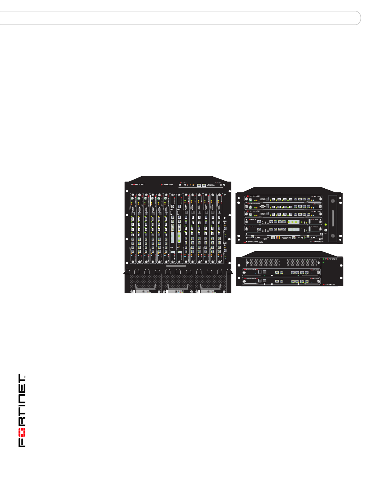
FortiGate-5000 series chassis
The FortiGate-5000 series Security Systems are chassis-based systems that
MSSPs and large enterprises can use to provide subscriber security services
such as firewall, VPN, antivirus protection, spam filtering, web filtering and
intrusion prevention (IPS). The wide variety of system configurations available
with FortiGate-5000 series provide flexibility to meet the changing needs of
growing high performance networks. The FortiGate-5000 series chassis support
multiple hot-swappable FortiGate-5000 series modules and power supplies. This
modular approach provides a scalable, high-performance and failure-proof
solution.
5140SAP
1311975312468101214
5140
PWR
PWR
PWR
PWR
PWR
ACC
ACC
ACC
CONSOLE
CONSOLE
USB
USB
1 2 3 4 5 6 7 8
1 2 3 4 5 6 7 8
STA IPM
STA IPM
STA IPM
PWR
ACC
ACC
ACC
MANAGEMENT
MANAGEMENT
E
T
H
CONSOLE
CONSOLE
USB
USB
1 2 3 4 5 6 7 8
1 2 3 4 5 6 7 8
STA IPM
O
CONSOLE
CONSOLE
USB
USB
SYSTEM
SYSTEM
CONSOLE
CONSOLE
R
S
2
3
2
1 2 3 4 5 6 7 8
1 2 3 4 5 6 7 8
Z
R
E
0
Z
R
E
1
Z
R
E
2
E1
E2
E2
1514
1312
1110
98
76
54
32
10
ZRE
ZRE
OKCLK
INTEXT
FLT
FLT
FLT
HOT SWAP
RESET
RESET
LED MODE
STA IPM
LED MODE
STA IPM
FILTER
012
FAN TRAY FAN TRAYFAN TRAY
SERIAL 1 SERIAL 2 ALARM
L
2
1
3
R
A
R
R
R
O
C
T
O
J
ER
E
E
N
TI
I
I
S
S
SE
A
S
R
U
U
U
M
E
M
C
R
USB
1 2 3 4 5 6 7 8
CONSOLE
5
ACC
PWR
PWR
PWR
PWR
PWR
ACC
ACC
ACC
CONSOLE
CONSOLE
E
T
H
O
R
S
2
3
2
Z
R
E
0
Z
R
E
1
Z
R
E
2
E1
1514
1312
1110
98
76
54
32
10
OKCLK
INTEXT
FLT
HOT SWAP
CONSOLE
USB
USB
1 2
1 2
3 4
3 4
5 6 7 8
5 6 7 8
STA IPM
STA IPM
STA IPM
PWR
ACC
ACC
ACC
CONSOLE
CONSOLE
USB
1 2
3 4
5 6 7 8
CONSOLE
USB
USB
USB
1 2
1 2
1 2
5000SM
ETH1
ETH0
10/100
10/100
link/Act
link/Act
3 4
3 4
3 4
ETH0
Service
RESET
STATUS
Hot Swap
5 6 7 8
5 6 7 8
5 6 7 8
12
5000SM
ETH0ETH1
10/100
10/100
link/Act
link/Act
ETH0
STA IPM
Service
STA IPM
STA IPM
RESET
STATUS
Hot Swap
PWR
USB
1 2 3 4 5 6 7 8
CONSOLE
4
ACC
PWR
USB
1 2 3 4 5 6 7 8
CONSOLE
ACC
PWR
3
ETH
O
RS232ZRE0ZRE1ZRE2
E1
1514
1312
2
1
5000SM
10/100
SMC
link/Act
ETH1
10/100
ETH0
link/Act
2
SYSTEM
CONSOLE
MANAGEMENT
ETH
O
RS232ZRE0ZRE1ZRE2
SYSTEM
CONSOLE
MANAGEMENT
5050SAP
ETH0
Service
SERIAL
STATUS
Hot Swap
RESET
1
USB
CONSOLE
RESET
STATUS
PWR
USB
CONSOLE
RESET
STATUS
PWR
1110
E2
E1
1514
1312
1110
E2
ALARM
162
162
OKCLK
9876543210
ZRE
OKCLK
9876543210
ZRE
SERIAL
2
3 4 5 6
IPM
3 4 5 6
IPM
STA IPM
STA IPM
STA IPM
INTEXT
FLT
HOT SWAP
RESET
POWER
LED MODE
FLT
INTEXT
FLT
HOT SWAP
RESET
LED MODE
FLT
5000SM
10/100
SMC
ETH0
Service
link/Act
STATUS
Hot Swap
10/100
RESET
ETH0ETH1
link/Act
1
PSU A
PSU B
ALT
ON/OFF
ALT
ON/OFF
FortiGate-5140 chassis
You can install up to 14 FortiGate-5000 series modules in the 14 slots of the
FortiGate-5140 ATCA chassis. The FortiGate-5140 is a 12U chassis that co nt a ins
two redundant hot swappable DC power entry modules that connect to -48 VDC
Data Center DC power. The FortiGate-5140 chassis also includes three hot
swappable cooling fan trays.
FortiGate-5050 chassis
You can install up to five FortiGate-5000 series modules in the five slots of the
FortiGate-5050 ATCA chassis. The FortiGate-5050 is a 5U chassis that contains
two redundant DC power connections that connect to -48 VDC Data Center DC
power. The FortiGate-5050 chassis also includes a hot swappable cooling fan
tray.
FortiGate Version 3 .0 MR4 Administration Guide
18 01-30004-0203-20070102
Page 19

Introduction Introducing the FortiGate units
FortiGate-5020 chassis
You can install one or two FortiGate-5000 series modules in the two slots of the
FortiGate-5020 ATCA chassis. The FortiGate-5020 is a 4U chassis that contains
two redundant AC to DC power supplies that connect to AC power. The
FortiGate-5020 chassis also includes an internal cooling fan tray.
About the FortiGate-5000 series modules
Each FortiGate-5000 series module is a standalone security system th at can also
function as part of an HA cluster. All FortiGate-5000 series modules are also hot
swappable. All FortiGate-5000 series units are high capacity security systems
with multiple gigabit interfaces, multiple virtual domain capacity, and other high
end FortiGate features.
FortiGate-5005FA2 module
The FortiGate-5001SX module is an independent high- performance security
system with eight Gigabit ethernet interfaces; two of which include Fortinet
technology to accelerate small packet performance. The FortiGate
module also supports high-end features including 802.1Q VLANs and multiple
virtual domains.
-5005FA2
FortiGate-5001SX module
The FortiGate-5001SX module is an independent high- performance security
system with eight Gigabit ethernet interfaces. The FortiGate
supports high-end features including 802.1Q VLANs and multiple virtual domains.
FortiGate-5001FA2 module
The FortiGate-5001FA2 module is an independent high-performance security
system with six Gigabit ethernet interfaces. The FortiGate-5001FA2 module is
similar to the FortiGate-5001SX module except that two of the FortiGate-5001FA2
interfaces include Fortinet technology to accelerate small packet performance.
FortiGate-5002FB2 module
The FortiGate-5002FB2 module is an independent high-performance FortiGate
security system with a total of 6 Gigabit ethernet interfaces. Two of the
FortiGate-5002FB2 interfaces include Fortinet technology to accelerate small
packet performance.
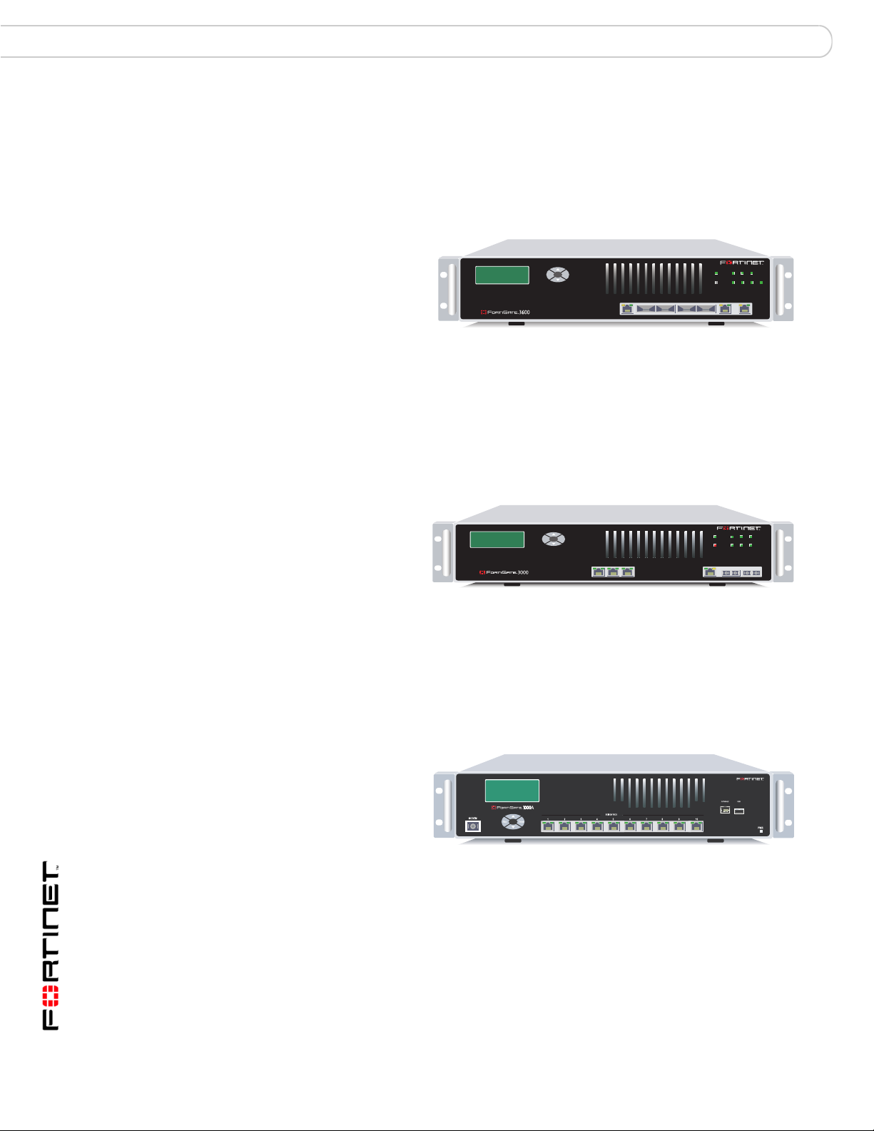
FortiGate-3600A
The FortiGate-3600A
unit provides carrierclass levels of
performance and
reliability demanded by
large enterprises and
service providers. The
unit uses multiple CPUs and FortiASIC chips to deliver throughput of 4Gbps,
Esc Enter
-5001SX module
2
7856341
CONSOLE
PWR
9
10
Hi-Temp
USB
MODEM
FortiGate Version 3 .0 MR4 Administration Guide
01-30004-0203-20070102 19
Page 20
Introducing the FortiGat e un i ts Introduction
meeting the needs of the most demanding applications. The FortiGate-3600A unit
includes redundant power supplies, which minimize single-point failures, and
supports load-balanced operation. The high-capacity, reliability and easy
management makes the FortiGate-3600A a natural choice for managed service
offerings.
FortiGate-3600
The FortiGate-3600
unit provides carrierclass levels of
performance and
reliability demanded by
Esc Enter
2
1
3 4 5/HA
large enterprises and
service providers. The
unit uses multiple CPUs and FortiASIC chips to deliver throughput of 4Gbps,
meeting the needs of the most demanding applications. The FortiGate-3600 unit
includes redundant power supplies, which minimize single-point failures, and
supports load-balanced operation. The high-capacity, reliability and easy
management makes the FortiGate-3600 a natural choice for managed service
offerings.
POWER
Hi-Temp 4
INTERNAL EXTERNAL
12
3
5/HA
EXT
INT
FortiGate-3000
The FortiGate-3000
unit provides the
carrier-class levels of
performance and
reliability demanded
by large enterprises
and service providers. The unit uses multiple CPUs and FortiASIC chips to deliver
a throughput of 3Gbps, meeting the needs of the most demanding applications.
The FortiGate-3000 unit includes redundant power supplies to minimize singlepoint failures, including load-balanced operation and redundant failover with no
interruption in service. The high capacity, reliability, and easy management of the
FortiGate-3000 makes it a natural choice for managed service offerings.
FortiGate-1000A
The FortiGate-1000A
Security System is a
high-performance
solution for the most
demanding large
enterprise and service
providers. The
FortiGate-1000A automatically keeps up to date information on Fortinet’s
FortiGuard Subscription Services by the FortiGuard Distribution Network,
ensuring around-the-clock protection against the latest viruses, worms, trojans
and other threats. The FortiGate-1000A has flexible architecture to quickly adapt
to emerging technologies such as IM, P2P or VOIP including identity theft
methods such as spyware, phishing and phar m i ng attacks.
Esc Enter
POWER
12
4/HA
Hi-Temp
INT
123 4/HA INTERNAL EXTERNAL
3
EXT
FortiGate Version 3 .0 MR4 Administration Guide
20 01-30004-0203-20070102
Page 21
Introduction Introducing the FortiGate units
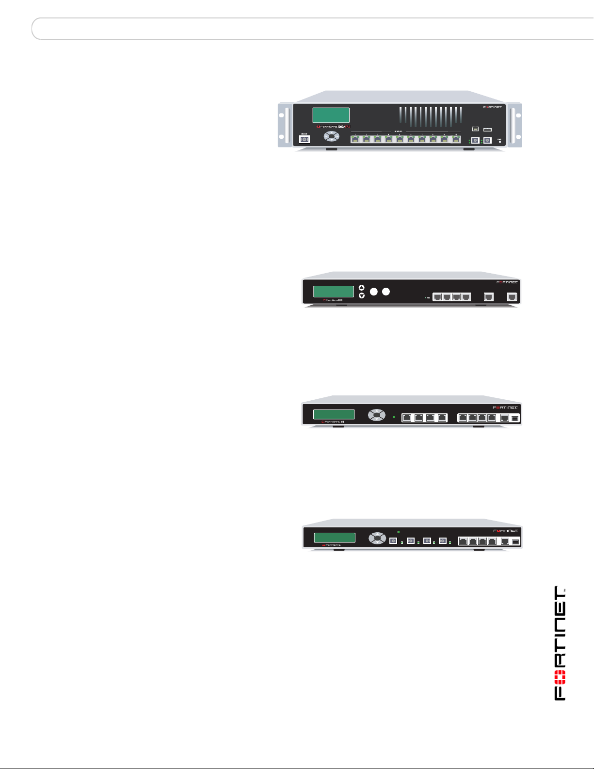
FortiGate-1000AFA2
The FortiGate1000AFA2 Security
System is a
high-performance
solution for the most
CONSOLE
USB
A2A1
demanding large
enterprise and service
providers. The FortiGate-1000AFA2 features two extra optical fiber ports with
Fortinet’s FortiAccel™ technology, enhancing small packet performance. The
FortiGate-1000AFA2 also delivers critical security functions in a hardened security
platform, tuned for reliability, usability, rapid deployment, low operational costs
and most importantly a superior detection rate against known and unknown
anomalies.
FortiGate-1000
The FortiGate-1000 unit is
designed for larger
enterprises. The FortiGate-
Enter
Esc
1000 meets the needs of
the most demanding applications, using multiple CPUs and FortiASIC chips to
deliver a throughput of 2Gps. The FortiGate-1000 unit includes support for
redundant power supplies to minimize single-port failures, load-balanced
operation, and redundant failover with no interruption in service.
1234 / HA
INTERNAL
EXTERNAL
FortiGate-800
FortiGate-800F
The FortiGate-800 provides
high throughput, a total of
eight network connections,
8
Esc Enter
INTERNAL EXTERNAL DMZ HA
PWR
123
4 USB
CONSOLE
(four of which are userdefined), VLAN support, and virtual domains. The FortiGate-800 also provides
stateful failover HA, when you are configuring a cluster of FortiGate units.The
FortiGate-800 is a natural choice for large enterprises, who demand top network
security performance.
The FortiGate-800F
provides the same features
as the FortiGate-800, using
800F
PWR
INTERNAL EXTERNAL DMZ HA 1 2 3
Esc Enter
CONSOLE
4 USB
four fibre-optic Internal,
External, DMZ and HA interfaces. The FortiGate-800F also provides stateful
failover HA, and support for the RIP and OSPF routing protocols. The FortiGate800F provides the flexibility, reliability and easy management large enterprises
are looking for.
FortiGate Version 3 .0 MR4 Administration Guide
01-30004-0203-20070102 21
Page 22
Introducing the FortiGat e un i ts Introduction
FortiGate-500A
The FortiGate-500A unit
provides the carrier-class
levels of performance and
reliability demanded by
CONSOLE
Esc Enter
A
USB LAN
L1 L2 L3
L4
12 3 4
10/100 10/100/1000
56
large enterprises and
service providers. With a total of 10 network connections, (including a 4-port LAN
switch), and high-availability features with automatic failover with no session loss,
the FortiGate-500A is the choice for mission critical applications. The flexibility,
reliability, and easy management of the FortiGate-500A makes it a natural choice
for managed service offerings.
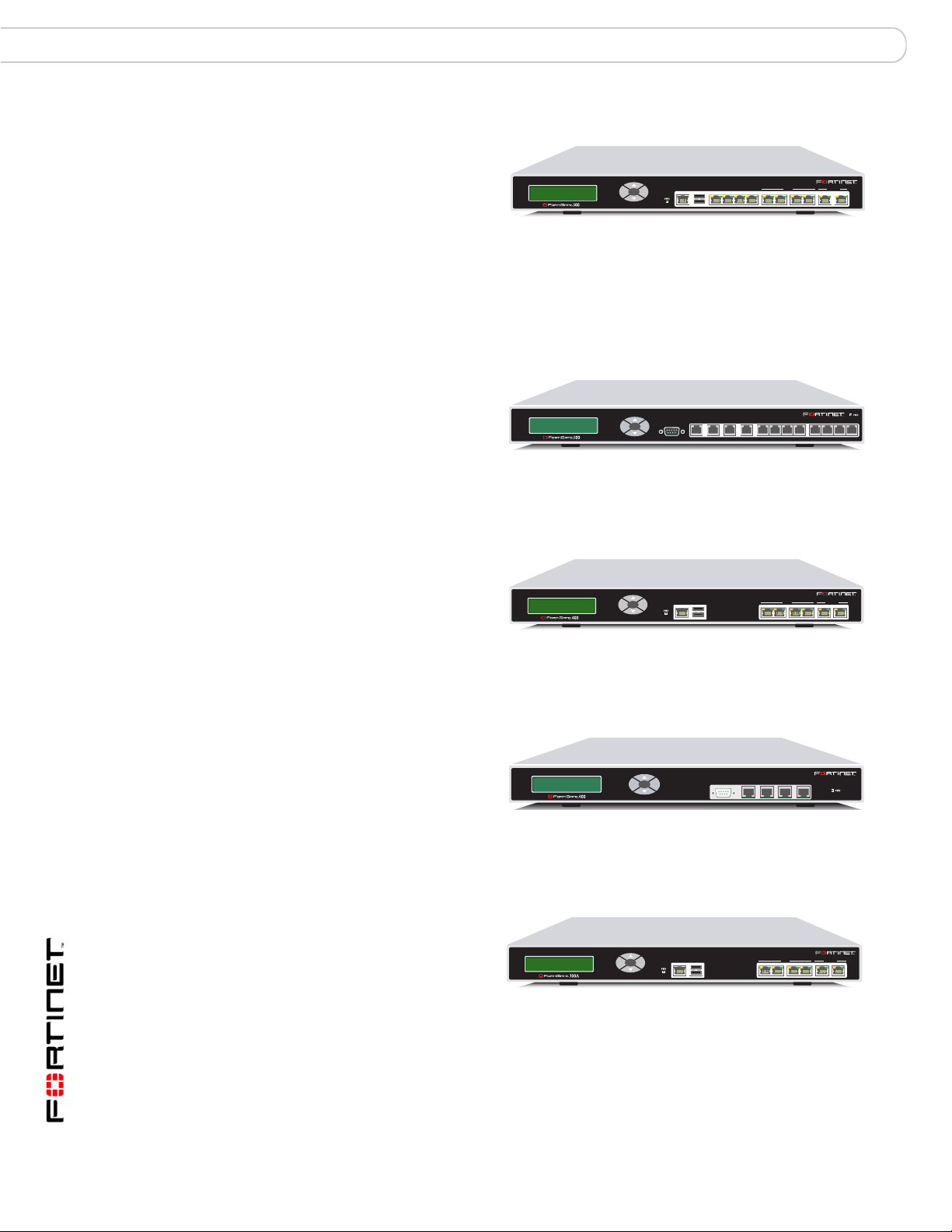
FortiGate-500
The FortiGate-500 unit is
designed for larger
INTERNAL
EXTERNAL 1 2 3 4 5 6 7 8
enterprises. The flexibility,
Esc Enter
reliability, and easy
management makes the
FortiGate-500 a natural choice for managed service offerings. The FortiGate-500
supports high availability (HA).
HADMZ
FortiGate-400A
FortiGate-400
FortiGate-300A
The FortiGate-400A unit
meets enterprise-class
requirements for
performance, availability,
Esc Enter
A
CONSOLE 10/100 10/100/1000USB
1 2 3 4 5 6
and reliability. The
FortiGate-400A also supports high availability (HA) and features automatic
failover with no session loss, making it the choice for mission critical applications.
The FortiGate-400 unit is
designed for larger
enterprises. The FortiGate-
Esc Enter
1
CONSOLE
4 / HA3
2
400 unit is capable of
throughput up to 500Mbps
and supports high availability (HA), which includes automatic failover with no
session loss.
The FortiGate-300A unit
meets enterprise-class
requirements for
Esc Enter
CONSOLE 10/100 10/100/1000USB
1 2 3 4 5 6
performance, availability,
and reliability. The
FortiGate-300A also supports high availability (HA) and includes automatic
failover with no session loss, making the FortiGate-300A a good choice for
mission critical applications.
FortiGate Version 3 .0 MR4 Administration Guide
22 01-30004-0203-20070102
Page 23
Introduction Introducing the FortiGate units
FortiGate-300
The FortiGate-300 unit is
designed for larger
enterprises. The FortiGate-
Esc Enter
300 unit features high
availability (HA), which
includes automatic failover with no session loss. This feature makes the
FortiGate-300 an excellent choice for mission-critical applications.
FortiGate-200A
The FortiGate-200A unit is
an easy-to-deploy and
easy-to-administer solution
that delivers exceptional
Esc Enter
A
1234
DMZ2DMZ1INTERNAL WAN1 WAN2CONSOLE USB
value and performance for
small office, home office and branch office applications.
FortiGate-200
The FortiGate-200 unit is
designed for small
INTERNALPOWER STATUS
DMZ
businesses, home offices or
EXTERNAL
even branch office
applications. The FortiGate200 unit is an easy-to-deploy and easy-to-administer solution. The FortiGate-200
also supports high availability (HA).
INTERNAL
CONSOLE
DMZ
EXTERNAL
FortiGate-100A
FortiGate-100
The FortiGate-100A unit is
designed to be an
easy-to-administer solution for
small offices, home offices, and
WAN 1 WAN 2
PWR STATUS
A
DMZ 1
LINK 100 LINK 100 LINK 100 LINK 100 LINK 100 LINK 100 LINK 100 LINK 100
DMZ 2
INTERNAL
4321
branch office applications.
The FortiGate-100A supports advanced features such as 80 2.1Q VLAN, virtu al
domains, and the RIP and OSPF routing protocols.
The FortiGate-100 unit is designed
for SOHO, SMB and branch office
applications.
The FortiGate-100 supports
INTERNAL
EXTERNAL
POWER
DMZ
STATUS
advanced features such as 802.1Q
VLAN, virtual domains, high availability (HA), and the RIP and OSPF routing
protocols.
FortiGate Version 3 .0 MR4 Administration Guide
01-30004-0203-20070102 23
Page 24
Introducing the FortiGat e un i ts Introduction
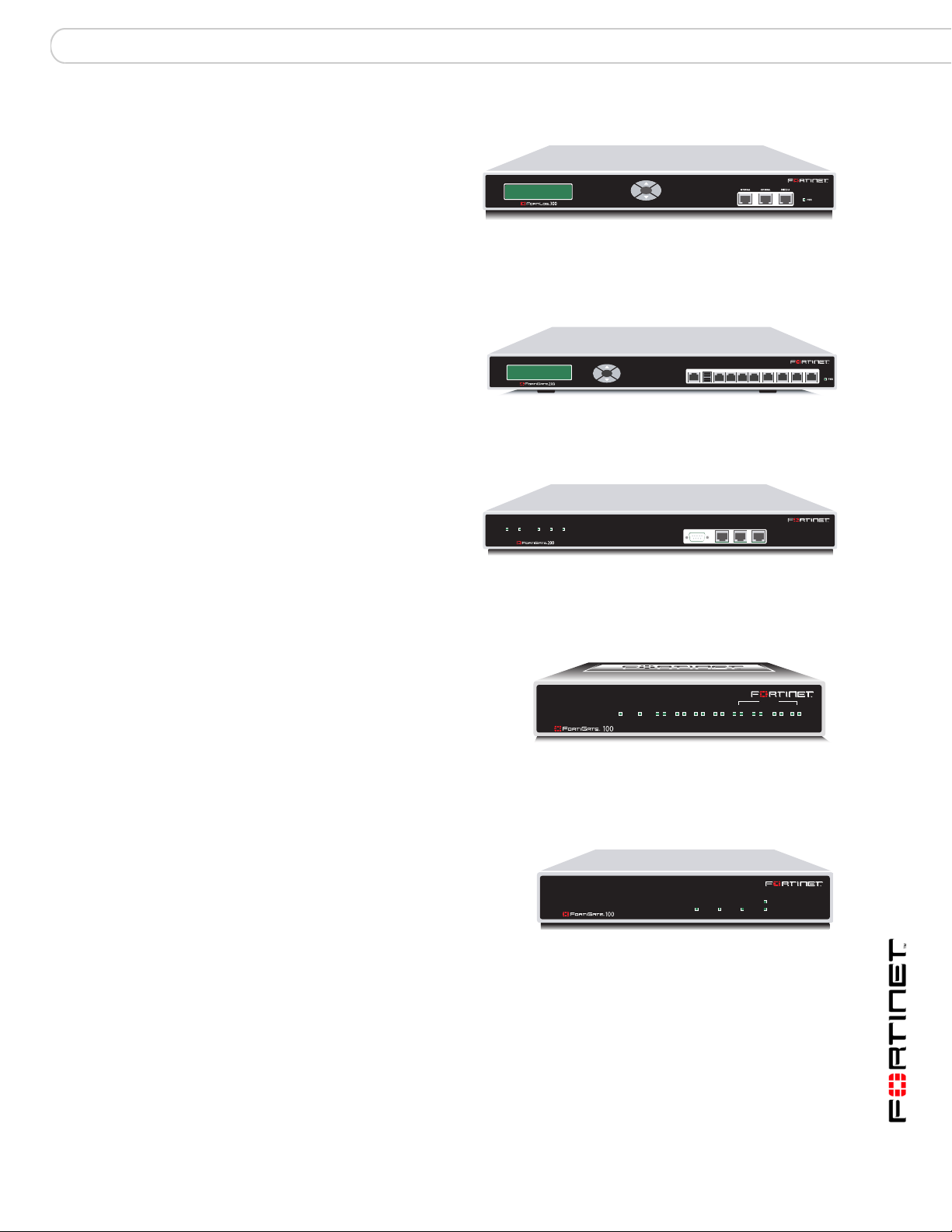
FortiGate-60/60M/ADSL
The FortiGate-60 unit is designed
for telecommuters remote offices,
and retail stores. The FortiGate-60
unit includes an external modem
PWR STATUS
INTERNAL
LINK 100 LINK 100 LINK 100 LINK 100 LINK 100 LINK 100 LINK 100
DMZ4321
WAN1 WAN2
port that can be used as a backup
or stand alone connection to the
Internet while the FortiGate-60M unit includes an internal mod em that can also be
used either as a backup or a standalone connection to the Internet. The FortiGate60ADSL includes an internal ADSL modem.
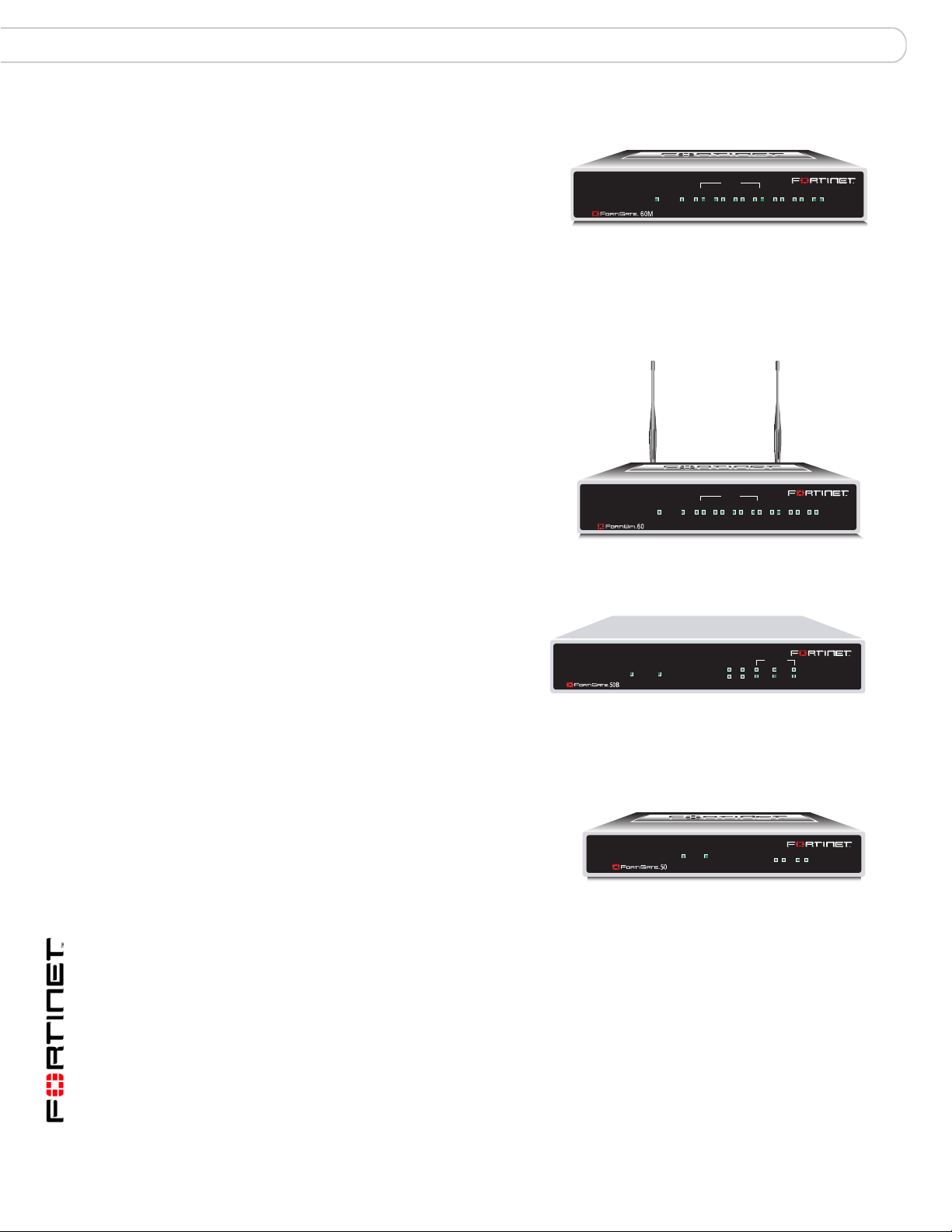
FortiWiFi-60/60A/60AM
The FortiWiFi-60 model provides a
secure, wireless LAN solution for
wireless connections. It combines
mobility and flexibility with FortiWiFi
Antivirus Firewall features, and can
be upgraded to future radio
technologies. The FortiWiFi-60
serves as the connection point
between wireless and wired networks
or the center-point of a standalone
wireless network.
PWR WLAN
INTERNAL
LINK 100 LINK 100 LINK 100 LINK 100 LINK 100 LINK 100 LINK 100
DMZ4321
WAN1 WAN2
FortiGate-50B
FortiGate-50A
The FortiGate-50B is designed for
telecommuters and small remote
offices with 10 to 50 employees.
The FortiGate-50B unit includes
POWER STATUS
WAN1 WAN2
INTERNAL
LINK / ACT
10/100
321
two WAN interfaces for redundant
connections to the Internet. The
FortiGate-50B unit also features a 3-port switch for internal network connections
and supports HA configurations with other FortiGate-50B units.
The FortiGate-50A unit is designed for
telecommuters and small remote
offices with 10 or fewer employees.
The FortiGate-50 unit includes an
STATUS
A
INTERNAL EXTERNAL
LINK 100 LINK 100
PWR
external modem port that can be used
as a backup or stand alone connection to the Internet.
FortiGate Version 3 .0 MR4 Administration Guide
24 01-30004-0203-20070102
Page 25

Introduction Fortinet family of products
Fortinet family of products
Fortinet offers a family of products that includes both software and hardware
appliances for a complete network security solution including mail, logging,
reporting, network management, and securi ty alon g with FortiGate Unified Threat
Manager Systems. For more information on the Fortinet product family, go to
www.fortinet.com/products.
FortiGuard Subscription Services
FortiGuard Subscription Services are security services created, updated and
managed by a global team of Fortinet security professionals. They ensure the
latest attacks are detected and blocked before harming your corporate resources
or infecting your end-user computing devices. These services are created with the
latest security technology and designed to operate with the lowest possible
operational costs.
FortiGuard Subscription Services includes:
• FortiGuard Antivirus Service
• FortiGuard Intrusion Prevention subscription services (IPS)
• FortiGuard Web Filtering
• FortiGuard Antispam Service
• FortiGuard Log and Analysis
• FortiGuard Premier Service
An online virus scan ner and virus encyclopedia is also available for yo ur reference
from the FortiGuard Center.
FortiAnalyzer
FortiClient
FortiAnalyzer™ provides network administrators with the info rmation they need to
enable the best protection and security for their networks against attacks and
vulnerabilities. FortiAnalyzer features include:
• collects logs from FortiGate devices and syslog devices and FortiClient
• creates hundreds of reports using collected log data
• scans and reports vulnerabilities
• stores files quarantined from a FortiGate unit
The FortiAnalyzer unit can also be configured as a network analyzer to capture
real-time traffic on areas of your network where firewalls are not employed. You
can also use the unit as a storage device where users can access and sh are files,
including the reports and logs that are saved on the FortiAnalyzer hard disk.
FortiClient™ Host Security software provides a secure computing environment for
both desktop and laptop users running the most popular Microsoft Windows
operating systems. FortiClient offers many features including:
• creating VPN connections to remote networks
• configuring real-time protection against viruses
• guarding against modification of the Windows registry
• virus scanning.
FortiGate Version 3 .0 MR4 Administration Guide
01-30004-0203-20070102 25
Page 26

Fortinet family of products Introduction
FortiClient also offers a silent installation feature, enabling an administrator to
efficiently distribute FortiClient to several users’ computers with preconfigured
settings.
FortiManager
FortiManager™ meets the needs of large enterprises (including managed security
service providers) responsible for establishing and maintaining security policies
across many dispersed FortiGate installations. With FortiManager you can
configure multiple FortiGate devices and monitor their status. You can also view
real-time and historical logs for FortiGate devices. FortiManager emp hasizes ease
of use, including easy integration with third party systems.
FortiBridge
FortiBridge™ products are designed to provide enterprise or ganizations operating
FortiGate units in Transparent mode with continuous network traffic flow in the
event of a power outage or a FortiGate system failure. The FortiBridge unit
bypasses the FortiGate unit to make sure that the network can continue
processing traffic. FortiBridge products are easy to use and deploy, including
providing customizable actions a FortiBridge unit takes in the event of a power
outage or FortiGate system failure.
FortiMail
FortiReporter
FortiMail™ provides powerful, flexible heuristic scanning and reporting capabilities
to incoming and outgoing email traffic. The FortiMail unit ha s reliable, high
performance features for detecting and blocking malicious att achments and sp am,
such as FortiGuard Antispam/Antivirus support, heuristic scanning, greylisting,
and Bayesian scanning. Built on Fortinet’s award winning For tiOS and FortiASIC
technology, FortiMail antivirus technology extends full content inspection
capabilities to detect the most advanced email threats.
FortiReporter Security Analyzer software generates easy-to-understand reports
and can collect logs from any FortiGate unit, as well as over 30 network and
security devices from third-party vendors. FortiReporter reveals network abuse,
manages bandwidth requirements, monitors web usage, and ensures employees
are using the office network appropriately. FortiReporter allows IT administrators
to identify and respond to attacks, including identifying ways to proactively secure
their networks before security threats arise.
FortiGate Version 3 .0 MR4 Administration Guide
26 01-30004-0203-20070102
Page 27

Introduction About this document
About this document
This FortiGate Version 3.0 MR4 Administration Guide provides detailed
information about FortiGate™ web-based manager options a nd ho w to use them.
This guide also contains some information about the FortiGate CLI.
This administration guide describes web-based manager functions in the same
order as the web-based manager menu. The document begins with a general
description of the FortiGate web-based manager and a description of FortiGate
virtual domains. Following these chapters, each item in the System menu, Router
menu, Firewall menu, and VPN menu gets a separate chapter. Then User,
AntiVirus, Intrusion Protection, Web Filter, AntiSpam, IM/P2P, and Log & Report
are all described in single chapters. The document concludes with a detailed
index.
The most recent version of this document is available from the FortiGate page of
the Fortinet Technical Documentation web site. The information in this document
is also available in a slightly different form as FortiGate web-based manager
online help.
You can find more information about FortiOS v3.0 from the FortiGate page of the
Fortinet T echnical Document ation web site as well as from the Fortinet Knowledge
Center.
This administration guide contains the following chapters:
• Web-based manager provides an introduction to the features of the FortiGate
web-based manager and includes information about how to register a
FortiGate unit and about how to use the web-based manager online help.
• System Status describes the System Status page, the dashboard of your
FortiGate unit. At a glance you can view the current system status of the
FortiGate unit including serial number, uptime, FortiGuard license information,
system resource usage, alert messages and network statistics. This section
also describes status changes that you can make, including changing the unit
firmware, host name, and system time.
• Using virtual domains describes how to use virtual domains to operate your
FortiGate unit as multiple virtual FortiGate units, providing separate firewall
and routing services to multiple networks.
• System Network explains how to configure physical and virtual interfaces an d
DNS settings on the FortiGate unit.
• System Wireless describes how to configure the Wireless LAN interface on a
FortiWiFi-60 unit.
• System DHCP provides information about how to configure a FortiGate
interface as a DHCP server or DHCP relay agent.
• System Config contains procedures for configuring HA and virtual clustering,
configuring SNMP and replacement messages, and changing the operation
mode.
• System Admin guides you through adding and editing administrator accounts,
defining access profiles for administrators, configuring Fo rtiManager™ access,
and defining general administrative settings such as language, timeouts, and
web administration ports.
• System Maintenance details how to back up and restore the system
configuration using a management computer or the FortiUSB device, enable
FortiGuard services and FortiGuard Distribution Network (FDN) updates, and
enter a license key to increase the maximum number of virtual domains.
FortiGate Version 3 .0 MR4 Administration Guide
01-30004-0203-20070102 27
Page 28

About this document Introduction
• System Chassis (FortiGate-5000 series) describes information displayed on
the system chassis web-based manager pages about all of the hardware
components in your FortiGate-5140 or FortiG at e- 50 5 0 cha ssis.
• Router Static explains how to define static routes and create route policies. A
static route causes packets to be forwarded to a destination other than the
factory configured default gateway.
• Router Static explains how to define static routes and create route policies. A
static route causes packets to be forwarded to a destination other than the
factory configured default gateway.
• Router Dynamic contains information about how to configure dynamic
protocols to route traffic through large or complex networks.
• Router Monitor explains how to interpret the Routing Monitor list. The list
displays the entries in the FortiGate routing table.
• Firewall Policy describes how to add firewall policies to control connections
and traffic between FortiGate interfaces, zones, and VLAN subinterfaces.
• Firewall Address describes how to configure addresses and address groups
for firewall policies.
• Firewall Service describes available services and how to configure service
groups for firewall policies.
• Firewall Schedule describes how to configure one-time and recurring
schedules for firewall policies.
• Firewall Virtual IP describes how to configure and use virtual IP addresses and
IP pools.
• Firewall Protection Profile describes how to configure protection profiles for
firewall policies.
• VPN IPSEC provides information about the tunnel-mode and route-based
(interface mode) Internet Protocol Security (IPSec) VPN options available
through the web-based manager.
• VPN PPTP explains how to use the web-based manager to spec ify a range of
IP addresses for PPTP clients.
• VPN SSL provides information about basic SSL VPN settings.
• VPN Certificates explains how to manage X.509 security certificates.
• User details how to control access to network resources through user
authentication.
• AntiVirus explains how to enable antivirus options when you create a firewall
protection profile.
• Intrusion Protection explains how to configure IPS options when a firewall
protection profile is created.
• Web Filter explains how to configure web filter options when a firewall
protection profile is created.
• Antispam explains how to configure spam filter options when a firewall
protection profile is created.
• IM, P2P & VoIP explains how to configure IM, P2P, and VoIP options when a
firewall protection profile is created. You can view IM, P2P, and VoIP statistics
to gain insight into how the protocols are being used within the network.
• Log&Report describes how to enable logging, view log files, and view the basic
reports available through the web-based manager.
FortiGate Version 3 .0 MR4 Administration Guide
28 01-30004-0203-20070102
Page 29

Introduction FortiGate documentation
Document conventions
The following document conventions are used in this guide:
• In the examples, private IP addresses are used for both private and public IP
addresses.
• Notes and Cautions are used to provide important information:
Note: Highlights useful additional information.
Caution: Warns you about commands or procedures that could have unexpected or
!
undesirable results including loss of data or damage to equipment.
Typographic conventions
Fortinet documentation uses the following typographical conventions:
Convention Example
Menu commands Go to VPN > IPSEC > Phase 1 and select Create New.
Keyboard input In the Gateway Name field, type a name for the remote VPN
Code examples config sys global
CLI command syntax config firewall policy
Document names FortiGate Administration Guide
File content <HTML><HEAD><TITLE>Firewall
Program output Welcome!
Variables
peer or client (for example, Central_Office_1).
set ips-open enable
end
edit id_integer
set http_retry_count <retry_integer>
set natip <address_ipv4mask>
end
Authentication</TITLE></HEAD>
<BODY><H4>You must authenticate to use this
service.</H4>
<address_ipv4>
FortiGate documentation
The most up-to-date publications and previous releases of Fortinet product
documentation are available from the Fortinet Technical Documentation web site
at http://docs.forticare.com.
The following FortiGate product documentation is available:
• FortiGate QuickStart Guide
Provides basic information about connecting and installing a FortiGate unit.
FortiGate Version 3 .0 MR4 Administration Guide
01-30004-0203-20070102 29
Page 30

FortiGate documentation Introduction
• FortiGate Installation Guide
Describes how to install a FortiGate unit. Includes a hardware reference,
default configuration information, installation procedures, connection
procedures, and basic configuration procedures. Choose the guide for you r
product model number.
• FortiGate Administration Guide
Provides basic information about how to configure a FortiGate unit, including
how to define FortiGate protection profiles and firewall policies; how to apply
intrusion prevention, antivirus protection, web content filtering, and spam
filtering; and how to configure a VPN.
• FortiGate online help
Provides a context-sensitive and searchable version of the Administration
Guide in HTML format. You can access online help from the web-based
manager as you work.
• FortiGate CLI Reference
Describes how to use the FortiGate CLI and contains a reference to all
FortiGate CLI commands.
• FortiGate Log Message Reference
Available exclusively from the Fortinet Knowledge Center, the FortiGate Log
Message Reference describes the structure of FortiGate log messages and
provides information about the log messages that are generated by FortiGate
units.
• FortiGate High Availability Overview and FortiGate High Availability User
Guide
These documents contain in-depth information about the F ort iG ate High
Availability (HA) feature and the FortiGate clustering protocol.
• FortiGate IPS User Guide
Describes how to configure the FortiGate Intrusion Preventio n System settings
and how the FortiGate IPS deals with some common attacks.
• FortiGate IPSec VPN User Guide
Provides step-by-step instructions for configuring IPSec VPNs using the webbased manager.
• FortiGate SSL VPN User Guide
Compares FortiGate IPSec VPN and FortiGate SSL VPN technology, and
describes how to configure web-only mode and tunnel-m ode SSL VPN access
for remote users through the web-based manager.
• FortiGate PPTP VPN User Guide
Explains how to configure a PPTP VPN using the web-based manager.
• FortiGate Certificate Management User Guide
Contains procedures for managing digital certificates including generating
certificate requests, installing signed certificates, importing CA root certificates
and certificate revocation lists, and backing up and resto ring installed
certificates and private keys.
• FortiGate VLANs and VDOMs User Guide
Describes how to configure VLANs and VDOMS in both NAT/Route and
Transparent mode. Includes detailed examples.
FortiGate Version 3 .0 MR4 Administration Guide
30 01-30004-0203-20070102
Page 31

Introduction Customer service and technical support
Fortinet Tools and Documentation CD
All Fortinet documentation is available from th e Fortinet Tools and Documentation
CD shipped with your Fortinet product. The documents on this CD are current for
your product at shipping time. For the latest versions of all Fortinet documentation
see the Fortinet Technical Documentation web site at http://docs.forticare.com.
Fortinet Knowledge Center
Additional Fortinet technical documentation is available from the Fortinet
Knowledge Center. The knowledge center contains troubleshooting and how-to
articles, FAQs, technical notes, and more. Visit the Fortinet Knowledge Center at
http://kc.forticare.com.
Comments on Fortinet technical documentation
Please send information about any errors or omissions in this document, or any
Fortinet technical documentation, to techdoc@fortinet.com.
Customer service and technical support
Fortinet Technical Support provides services designed to make sure that your
Fortinet systems install quickly, configure easily, and operate reliably in your
network.
Please visit the Fortinet Technical Support web site at http://support.fortinet.com
to learn about the technical support services that Fortinet provides.
FortiGate Version 3 .0 MR4 Administration Guide
01-30004-0203-20070102 31
Page 32

Customer service and technical support Introduction
FortiGate Version 3 .0 MR4 Administration Guide
32 01-30004-0203-20070102
Page 33

Web-based manager
Web-based manager
This section describes the features of the user-friendly web-b ased manager
administrative interface of your FortiGate unit.
Using HTTP or a secure HTTPS connection from any computer running a web
browser, you can configure and manage the FortiGate unit. The web-based
manager supports multiple languages. You can configure the FortiGate unit for
HTTP and HTTPS administration from any FortiGate interface.
Figure 1: Example FortiGate-5001SX Web-based manager dashboard
You can use the web-based manager to configure most FortiGate settings and to
monitor the status of the FortiGate unit. Configu ra tio n ch an ge s ma d e us in g the
web-based manager are effective immediately without resetting the firewall or
interrupting service. Once you are satisfied with a configuration, you can back it
up. The saved configuration can be restored at an y tim e.
The following topics are included in this section:
• Button bar features
• Web-based manager pages
FortiGate Version 3.0 MR4 Administration Guide
01-30004-0203-20070102 33
Page 34

Button bar features Web-based manager
Button bar features
The button bar in the upper right corner of the web-based manager provides
access to several important FortiGate features.
Figure 2: Web-based manager button bar
Contact Customer Support
Logout
Online Help
Contact Customer Support
The Contact Customer Support button opens the Fortinet Support web page in a
new browser window. From this page you can:
• Access the Fortinet Knowledge Center.
• Log into Customer Support (Support Login).
• Register your FortiGate unit (Product Registration).
• Find out about Fortinet Training and Certification.
•Visit the FortiGuard Center.
To register your FortiGate unit, go to Product Registration and follow the
instructions.
Using the Online Help
The Online Help button displays online help for the current web-based manag er
page. The online help page that is displayed cont ains info rmation a nd procedur es
related to the controls on the current web-based manager page. Most help pages
also contains hyperlinks to related topics. The online help system also includes a
number of controls that you can use to find additional information.
Figure 3: Viewing system status online help page
Show Navigation
Previous
Next
Bookmark
Print
Email
FortiGate Version 3 .0 MR4 Administration Guide
34 01-30004-0203-20070102
Page 35

Web-based manager Button bar features
Show
Navigation
Previous Display the previous page in the online help.
Next Display the next page in the online help.
Email Send an email to Fortinet Technical Documentation at
Print Print the current online help page.
Bookmark Add an entry for this online help page to your browser bookmarks or
Open the online help navigation pane. From the navigation pane you can
use the online help table of contents, index, and search to access all of
the information in the online help. The online help is organized in the
same way as the FortiGate web-based manager and the FortiGate
Administration Guide.
techdoc@fortinet.com. You can use this email address to let us know if
you have a comment about or correction for the online help or any other
Fortinet technical documentation product.
favorites list. Use this button to make it easier to find helpful online help
pages. You cannot use the Bookmark icon to add an entry to your
favorites list if you are viewing online help from Internet Explorer runnin g
on a management PC with Windows XP and service pack 2 installed.
Select Show Navigation to display the online help navigation pane.
Figure 4: Online help page with navigation pane
Contents SearchIndex Show in Contents
Contents Display the online help table of contents. You can navigate through the
Index Display the online help index. You can use the index to find information in
Search Display the online help search. See “About searching the online help” on
Show in
Contents
table of contents to find information in the online help. The online help is
organized in the same way as the FortiGate web-based manager and the
FortiGate Administration Guide.
the online help.
page 35 for information about how to search for information in the online
help.
If you have used the index, search, or hyperlinks to find information in the
online help, the table of contents may not be visible or the table of
contents may be out of sync with the current help page. You can select
Show in Contents to display the table of contents showing the location of
the current help page.
About searching the online help
Using the online help search, you can search for one word o r multiple words in the
full text of the FortiGate online help system. Please note the following about the
search:
• If you search for multiple words, the search finds help pages that co ntain all of
the words that you entered. The search does not find help pages that only
contain one of the words that you entered.
FortiGate Version 3 .0 MR4 Administration Guide
01-30004-0203-20070102 35
Page 36

Button bar features Web-based manager
• The help pages found by the search are ranked in orde r of rele van ce . Th e
higher the ranking, the more likely the help page includes useful or detailed
information about the word or words that you are searching for. Help pages
with one or more of the search words in the help page title are ranked highest.
• You can use the asterisk (*) as a search wildcard character that is replaced by
any number of characters. For example, if you search for auth* the search
finds help pages containing auth, authenticate, authentication,
authenticates, and so on.
• In some cases the search only finds exact matches. For example if you search
for windows the search may not find pages containing the word window. You
can work around this using the * wildcard (for example by searching for
window*).
To search in the help system
1 From any web-based manager page, select the online help button.
2 Select Show Navigation to display the online help navigation pane.
3 Select Search.
4 Type one or more words to search for in the search field and then press enter or
select Go.
The search pane lists the name s of all the on line help p ages tha t cont ain the wor d
or words that you entered. Select a name from the list to display that help page.
Logout
Using the keyboard to navigate in the online help
You can use the keyboard shortcuts listed in Table 1 to display and find
information in the online help.
Table 1: Online help navigation keys
Key Function
Alt+1 Display the table of contents.
Alt+2 Display the index.
Alt+3 Display the Search tab.
Alt+4 Go to the previous page.
Alt+5 Go to the next page.
Alt+7 Send an email to Fortinet Technical Documentation at
techdoc@fortinet.com. Y ou can use this email address to let us know if
you have a comment about or correction for the online help or any other
Fortinet technical documentation product.
Alt+8 Print the current online help page.
Alt+9 Add an entry for this online help page to your browser bookmarks or
favorites list. Use this button to make it easier to find helpful online help
pages.
The Logout button immediately logs you out of the web-based manager. Log out
before you close the browser window . If you simply close the browser or leave the
web-based manager, you remain logged-in until the idle timeout (default 5
minutes) expires.
FortiGate Version 3 .0 MR4 Administration Guide
36 01-30004-0203-20070102
Page 37

Web-based manager Web-based manager pages
Web-based manager pages
The web-based manager interface consists of a menu and pages, many of which
have multiple tabs. When you select a menu item, such as System, it expands to
reveal a submenu. When you select one of the submenu items, the associated
page opens at its first tab. To view a different tab, select the tab.
The procedures in this manual direct you to a page by specifying the menu item,
the submenu item and the tab, like this:
1 Go to System > Network > Interface.
Figure 5: Parts of the web-based manager (shown for the FortiGate-50B)
Menu
Web-based manager menu
The menu provides access to configuration options for all major features of the
FortiGate unit.
Tabs
Page
Button bar
System Configure system facilities, such as network interfaces, virtual domains,
Router Configure FortiGate static and dynamic routing.
Firewall Configure firewall policies and protection profiles that apply network
VPN Configure IPSec, SSL, and PPTP virtual private networking.
User Configure user accounts for use with firewall policies that require user
AntiVirus Configure antivirus protection.
Intrusion
Protection
Web Filter Configure web filtering.
FortiGate Version 3 .0 MR4 Administration Guide
01-30004-0203-20070102 37
DHCP services, High Availability (HA), system time and set system
options.
protection features. Also configure virtual IP addresses and IP pools.
authentication. Also configure external authentication servers such as
RADIUS, LDAP, and Windows AD.
Configure the FortiGate Intrusion Protection System (IPS).
Page 38

Web-based manager pages Web-based manager
AntiSpam Configure email spam filtering.
IM, P2P & VoIP Configure monitoring and control of internet messaging, peer-to-peer
Log & Report Configure logging, alert email, and FortiGuard Log and Analysis. View
messaging, and voice over IP (VoIP) traffic.
log messages and reports. Connect to a FortiAnalyzer to view log
messages and reports. View log messages stored by FortiGuard Log and
Analysis.
Lists
Many of the web-based manager pages are lists. There are lists of network
interfaces, firewall policies, administrators, users, and so on.
Figure 6: Example of a web-based manager list
Delete
Edit
Icons
The list shows some information about each item and the icons in the right-most
column enable you to take action on the item. In this example, you can select
Delete to remove the item or select Edit to modify the item.
To add another item to the list, you select Create New. This opens a dialog box in
which you define the new item. The dialog box for crea ting a new item is simila r to
the one for editing an existing item.
The web-based manager has icons in addition to buttons to enable you to interact
with the system. There are tooltips to assist you in underst anding the function of
the icon. Pause the mouse pointer over the icon to view the tooltip. Table 2
describes the icons that are available in the web-based manager.
Table 2: web-based manager icons
Icon Name Description
Change
Password
Clear Clear a log file.
Collapse Coll apse this section to hide some fields. This icon is used in
Change the administrator password. This icon appears in the
Administrators list if your access profile enables you to give
write permission to administrators.
some dialog boxes and some lists.
Column
Settings
Delete Delete an item. This icon appears in lists where the item can be
38 01-30004-0203-20070102
Select the columns to display. This icon is used in Log Access
and firewall Policy lists among others.
deleted and you have write permission on the page.
FortiGate Version 3 .0 MR4 Administration Guide
Page 39

Web-based manager Web-based manager pages
T able 2: web-based manager icons (Continued)
Icon Name Description
Description The tooltip for this icon displays the Description field for this
Download
or Backup
Download Download a Certificate Signing Request.
Edit Edit a configuration. This icon appears in lists where you have
Expand Expand this section to reveal more fields. This icon is used in
Filter Set a filter on one or more columns in this table. A dialog opens
Go Do a search.
Insert Policy
before
Move to Move item in list.
Next page View next page of list.
Previous
page
table entry.
Download a log file or back up a configuration file.
write permission on the page.
some dialog boxes and some lists.
in which you can specify filters. The icon is green on columns
where a filter is active, otherwise it is grey.
Create a new policy to precede the current one.
View previous page of list.
Refresh Update the information on this page.
Restore Restore a configuration from a file.
View View a configuration. This icon appears in list s instead of the
Edit icon when you do not have write permission on that page.
FortiGate Version 3 .0 MR4 Administration Guide
01-30004-0203-20070102 39
Page 40

Web-based manager pages Web-based manager
FortiGate Version 3 .0 MR4 Administration Guide
40 01-30004-0203-20070102
Page 41

System Status Status page
System Status
This section describes the System Status page, the dashboard of your FortiGate
unit. At a glance you can view the current system status of the FortiGate unit
including serial number, uptime, FortiGuard™ license information, system
resource usage, alert messages and network statistics.
Note: Your browser must support Javascript to view the System Status page.
The following topics are included in this section:
• Status page
• Changing system information
• Changing the FortiGate firmware
• Viewing operational history
• Manually updating FortiGuard definitions
• Viewing Statistics
• Topology viewer
Status page
Viewing system status
View the System Status page, also known as the system dashboard, for a
snapshot of the current operating status of the FortiGate unit. FortiGate
administrators whose access profiles permit read access to system configuration
can view system status information.
When the FortiGate unit is part of an HA cluster, the Status page includes basic
HA cluster status information including the name of the clu ste r an d th e clus te r
members including their hostnames. To view more complete status information for
the cluster, go to System > Config > HA. For more information, see “HA” on
page 119. HA is not available on FortiGate models 50A and 50AM.
FortiGate administrators whose access profiles permit write access to system
configuration can change or update FortiGate un it information . For infor mation on
access profiles, see “Access profiles” on page 148.
The System St atus page displays by default when you log in to the web-based
manager.
At any time, go to System > Status to view the System Status page.
To view this page, your access profile must permit read access to system
configuration. If you also have system configuration write access, you can modify
system information and update FortiGuard - AV and FortiGuard - IPS definitions.
For information on access profiles, see “Access profiles” on page 148.
FortiGate Version 3.0 MR4 Administration Guide
01-30004-0203-20070102 41
Page 42

Status page System Status
The System Status page is completely customizable. You can select which
displays to show, whe re they are located on the p age, and if they ar e minimized or
maximized. Each display has an icon associated with it for easy recognition when
minimized.
Figure 7: System Status page
Select Add Content to add any of the displays not currently shown on the System
Status p age. Any displays current on the System S tatus page will be greyed out as
you can only have one of each display on the System Status page. Optionally
select Back to default to restore the historic System Status page configuration.
Position your mouse over a display’s titlebar to see your available options for that
display. The options vary slightly from display to display.
Figure 8: A minimized display
Display title
Twistie arrow
Display Title Shows the name of the display
Twistie arrow Select to maximize or minimize the display.
Refresh icon Select to update the displayed information.
Close icon Select to close the display. You will be prompted to confirm the
close.
Refresh icon
Close icon
FortiGate Version 3 .0 MR4 Administration Guide
42 01-30004-0203-20070102
Page 43

System Status Status page
System information
Figure 9: Example FortiGate-5001 System Information
Serial Number The serial number of the current FortiGate unit. The seri al number is
Uptime The time in days, hours, and minutes since the FortiGate unit was last
System Time The current date and time according to the FortiGate unit internal
Host Name The host name of the current FortiGate unit.
Cluster Name The name of the HA cluster for this FortiGate unit. See “HA” on
Cluster Members The FortiGate units in the HA cluster. Information displayed about
Virtual Cluster 1
Virtual Cluster 2
Firmware Version The version of the firmware installed on the curr en t Fo rti Gate unit.
FortiClient Version The currently loaded version of FortiClient. Select Update to upload a
Operation Mode The operating mode of the current FortiGate unit. A FortiGate can
specific to the FortiGate unit and does not change with firmware
upgrades.
started.
clock.
Select Change to change the time or configure the FortiGate unit to
get the time from an NTP server. See “Configuring system time” on
page 49.
If the FortiGate unit is in HA mode, this field is not displayed.
Select Change to change the host name.
See “Changing the FortiGate unit host name” on page 50.
page 119.
The FortiGate unit must be operating in HA mode to display this field.
each member includes hostname, serial number, and if the unit is a
primary (master) or subordinate (slave) unit in the cluster. See “HA”
on page 119.
The FortiGate unit must be operating in HA mode with virtual
domains not enabled to display this field.
The role of each FortiGate unit in virtual cluster 1 and virtual cluster 2.
See “HA” on page 119.
The FortiGate unit must be operating in HA mode with virtual
domains enabled to display these fields.
Select Update to change the firmware.
See “Upgrading to a new firmware version” on page 51.
new FortiClient software image to this FortiGate unit from your
management computer.
This is available only on FortiGate models that provide a portal from
which hosts can download FortiClient software.
operated in NAT mode or T ransparent mode. Select change to switch
between NAT and Transparent mode. See “Changing operation
mode” on page 141
If virtual domains are enabled, this field shows the operating mode of
the current virtual domain. A virtual domain can be operating in either
NAT mode or Transparent mode.
FortiGate Version 3 .0 MR4 Administration Guide
01-30004-0203-20070102 43
Page 44

Status page System Status
Virtual Domain The status of virtual domains on your FortiGate unit. Select enable or
Current
Administrators
disable to change the status of virtual domains.
If you change the state of virtual domains, your session will be
terminated and you will need to login. For more information see
“Using virtual domains” on page 61.
The number of administrators currently logged into the FortiGate unit.
Select Details to view more information about each administrator that
is logged. The additional information includes user name, type of
connection, IP address they are connecting from, and when they
logged in.
License Information
License information displays the status of your FortiGate support contract, and
FortiGuard subscriptions. The FortiGate unit updates the license information
status indicators automatically by connecting to the FortiGuard network.
FortiGuard subscriptions status indicators are green for OK, grey if the FortiGate
unit cannot connect to the FortiGuard network, and yellow if the license has
expired.
Selecting any of the Configure options will take you to the maintenance page. For
more information, see “Syste m Ma in te na nc e” on page 157.
Figure 10: Example License Information
Support Contract The support contract number and expiry date.
If Not Registered is displayed, select Register to register the
unit.
If Renew is visible, you need to renew your support contract.
Contact your local reseller.
FortiGuard Subscriptions
AntiVirus The FortiGuard Antivirus license version, issue date and
AV Definitions The current installed version of the FortiGuard Antivirus
Intrusion Protection The FortiGuard intrusion protection license version, issue
IPS Definitions The current installed version of the Intrusion Prevention
44 01-30004-0203-20070102
service status. If your license has expired you can select
Renew two renew the license.
Definitions. To update the definitions manually, select
Update. For more information, see “Updating the FortiGuard
AV Definitions manually” on page 53.
date and service status. If your license has expired you can
select Renew two renew the license.
System (IPS) attack definitions. To update the definitions
manually, select Update. For more information, see
“Updating the FortiGuard IPS Definitions manually” on
page 53.
FortiGate Version 3 .0 MR4 Administration Guide
Page 45

System Status Status page
Web Filtering The FortiGuard Web Filtering license type, expiry date and
Antispam The FortiGuard Antispam license type, expiry date and
Log & Analysis The FortiGuard Log & Analysis license type, expiry date and
Virtual Domain The number of virtual domains the unit supports.
service status. If your license has expired you can select
Renew two renew the license.
service status. If your license has expired you can select
Renew two renew the license.
service status.
For FortiGate models 3000 or higher, you can select the
Purchase More link to purchase a license key through
Fortinet Support to increase the maximum number of
VDOMs. See “License” on page 172.
CLI Console
There are commands in FortiOS that are only accessible from the CLI. Generally
to use the CLI you connect via telnet or SSH using a 3rd party program.
The System Status page includes a fully functional CLI console. To use the
console, click on it and you are automatically logged in as the account you are
currently using in the GUI. The CLI console default view cannot be resized or
moved. You can cut & paste text from the CLI console.
Figure 11: CLI Console
Customize
icon
The two controls on the CLI console window are the customize icon, and the
Detach control.
The Detach control moves the CLI console into its own window that is free to
resize or be repositioned on your screen. The two controls on the detached CLI
console are Customize and Attach. Customize has been explained. Attach simply
puts the CLI console back in place on the System Status page.
The customize icon allows you to change the look of the console using fonts and
colors for the text and background.
FortiGate Version 3 .0 MR4 Administration Guide
01-30004-0203-20070102 45
Page 46

Status page System Status
Figure 12: Customize CLI Console window
Preview See how your changes will appear on the CLI console.
Text Select this control, then choose a color from the color matrix to the
Background Select this control, then choose a color from the color matrix to the
Use external
command input box
Console buffer length Select the number of lines the console buffer keeps in memory.
Font Select a font from the list.
Size Select the size of the font. The default size is 10.
Reset defaults Select to return to the default settings, discarding any changes.
OK Select to save your changes and return to the CLI console.
Cancel Select to discard your change and return to the CLI console.
right to change the color of the text in the CLI console.
right to change the color of the background in the CLI console.
Select to allow external input.
Valid numbers are from 20 to 9999.
System Resources
Any System Resources that are not displayed on the status page can be viewed
as a graph by selecting the History icon.
Figure 13: Example System Resources
History
FortiGate Version 3 .0 MR4 Administration Guide
46 01-30004-0203-20070102
Page 47

System Status Status page
History icon View a graphical representation of the last minute of CPU, memory,
CPU Usage The current CPU status displayed as a dial gauge and as a
Memory Usage The current memory status displayed as a dial gauge and as a
FortiAnalyzer Disk
Quota
sessions, and network usage. This page also shows the virus and
intrusion detections over the last 20 hours. For more information
see “Viewing operational history” on page 52.
percentage.
The web-based manager displays CPU usage for core processes
only. CPU usage for management processes (for example, for
HTTPS connections to the web-based manager) is excluded.
percentage.
The web-based manager displays memory usage for core
processes only. Memory usage for management processes (for
example, for HTTPS connections to the web-based manager) is
excluded.
The current status of the FortiAnalyzer disk quota used for the
FortiGate unit displayed as a pie chart and a percentage.
This is available only if you have configured logging to a
FortiAnalyzer unit.
Interface Status
An illustration of the FortiGate unit front panel shows the status of the unit’s
ethernet interfaces. If a network interface is shaded green, that interface is
connected. Pause the mouse pointer over the interface to view the IP address,
netmask and current status of the interface.
If you select Reboot or ShutDown a window will open allowing you to enter the
reason for the system event. Your reason will be added to the Disk Event Log.
Disk logging will need to be enabled in the CLI. Event Logging and Admin Events
need to be enabled. For more information on Event Logging, see “Event log” on
page 416.
Figure 14: Example FortiGate-800 interface status (with no FortiAnalyzer)
INT / EXT / DMZ / HA /
1 / 2 / 3 / 4
FortiAnalyzer The icon on the link between the FortiGate unit graphic and the
The ports on the FortiGate unit. The names and number of these
ports will vary with your unit.
The icon below the port name indicates its status by its color.
Green indicates the port is connected. Grey indicates there is no
connection.
For more information about a port’s configuration position your
mouse over the icon for that port. You will see the full name of the
interface, the IP address and netmask, the status of the link, the
speed of the interface, and the number of sent and received
packets.
FortiAnalyzer graphic indicates the status of their connection. An
‘X’ on a red icon indicates there is no connection. A check mark on
a green icon indicates there is communication between the two
units.
Select the FortiAnalyzer graphic to configure FortiAnalyzer logging
on your FortiGate unit. See “Log&Report” on page 407.
FortiGate Version 3 .0 MR4 Administration Guide
01-30004-0203-20070102 47
Page 48

Status page System Status
Reboot Select to shutdown and restart the FortiGate unit. You will be
Shutdown Select to shutdown the FortiGate unit. You will be prompted for
Reset Select to reset the FortiGate unit to factory default settings. You
prompted to enter a reason for the reboot that will be entered into
the logs.
confirmation. You will be prompted to enter a reason for the
shutdown that will be entered into the logs.
will be prompted for confirmation.
Alert Message Console
Alert messages help you track changes to your FortiGate unit. The following types
of messages can appear in the Alert Message Console:
Figure 15: Example Alert Message Console
System restart The system restarted. The restart could be due to
Firmware upgraded by
<admin_name>
Firmware downgraded by
<admin_name>
FortiGate has reached
connection limit for <n> seconds
Found a new FortiAnalyzer
Lost the connection to
FortiAnalyzer
operator action or power off/on cycling.
The named administrator upgraded the firmware to a
more recent version on either the active or non-active
partition.
The named administrator downgraded the firmware to
an older version on either the active or non-active
partition.
The antivirus engine was low on memory for the
duration of time shown. Depending on model and
configuration, content can be blocke d or pass
unscanned under these conditions.
Shows that the FortiGate unit has either found or lost
the connection to a FortiAnalyzer unit. See “Logging
to a FortiAnalyzer unit” on page 409.
Each message shows the date and time that it was posted. If there is insufficient
space for all of the messages, select Show All to view the entire list in a new
window.
T o clear alert messages, select All and then select Clear Alert Messages at the top
of the new window. This will delete all current alert messages from your FortiGate
unit.
Statistics
The statistics section of the status page is designed to allow you to see at a glance
what is happening on your FortiGate unit with regards to network traffic and
protection.
You can quickly see the amount and type of traffic as well as any attack attempts
on your system. To investigate an area that draws your attention, simply select
Details for a detailed list of the most recent activity.
FortiGate Version 3 .0 MR4 Administration Guide
48 01-30004-0203-20070102
Page 49

System Status Changing system information
The information displayed in the statistics section is saved in log files that can be
saved to a FortiAnalyzer unit, saved locally or backed up to an external source.
You can use this data to see trends in network activity or attacks over time and
deal with it accordingly.
For detailed procedures involving the statistics list, see “Viewing Statistics” on
page 54.
Figure 16: Example Statistics
Reset
Since The date and time when the counts were reset.
Counts are reset when the FortiGate unit reboots or when you
select to the reset icon.
Reset Icon Reset the Archive and Attack Log counts to zero.
Sessions The number of communications sessions being processed by the
Content Archive A summary of the HTTP, e-mail, FTP, and IM/P2P traffic that has
Attack Log A summary of viruses, attacks, spam email messages and URLs
FortiGate unit. Select Details for detailed information. See “Viewing
the session list” on page 54.
passed through the FortiGate unit. The Details pages list the last 64
items of the selected type and provide links to the FortiAnalyzer unit
where the archived traffic is stored. If logging to a FortiAnalyzer unit
is not configured, the Details pages provide a link to the
Log & Report > Log Config > Log Settings page.
the unit has intercepted. The Details pages list the most recent 10
items, providing the time, source, destination and other information.
Changing system information
FortiGate administrators whose access profiles permit write access to system
configuration can change the system time, host name and the operation mod e for
the VDOM.
Configuring system time
1 Go to System > Status.
2 In the System Information section, select Change on the System Time line.
3 Select the time zone and then either set the date and time manually or configure
synchronization with an NTP server.
FortiGate Version 3 .0 MR4 Administration Guide
01-30004-0203-20070102 49
Page 50

Changing system information System Status
Figure 17: Time Settings
System Time The current FortiGate system date and time.
Refresh Update the display of the current FortiGate system date and time.
Time Zone Select the current FortiGate system time zone.
Automatically adjust
clock for daylight
saving changes
Set Time Select to set the FortiGate system date and time to the values you
Synchronize with
NTP Server
Server Enter the IP address or domain name of an NTP server. To find an
Sync Interval Specify how often the FortiGate unit should synchronize its time
Select to automatically adjust the FortiGate system clock when your
time zone changes between daylight saving time and standard
time.
set in the Hour, Minute, Second, Year, Month and Day fields.
Select to use an NTP server to automatically set the system date
and time. You must specify the server and synchronization interval.
NTP server that you can use, see http://www.ntp.org.
with the NTP server. For example, a setting of 1440 minutes causes
the FortiGate unit to synchronize its ti me onc e a d ay.
Changing the FortiGate unit host name
The FortiGate host name appears on the Status page and in the FortiGate CLI
prompt. The host name is also used as the SNMP system name. For information
about SNMP, see “SNMP” on page 127.
The default host name is the FortiGate unit serial number. For example
FGT8002805030003 would be a FortiGate-800 unit.
Administrators whose access profiles permit system configuration write access
can change the FortiGate unit host name.
Note: If the FortiGate unit is part of an HA cluster, you should use a unique hostname to
distinguish the unit from others in the cluster.
To change the FortiGate unit host name
1 Go to System > Status.
2 In the Host Name field of the System Information section, select Change.
3 In the New Name field, type a new host name.
4 Select OK.
The new host name is displayed in the Host Name field, and in the CLI prompt,
and is added to the SNMP System Name.
FortiGate Version 3 .0 MR4 Administration Guide
50 01-30004-0203-20070102
Page 51

System Status Changing the FortiGate firmware
Changing the FortiGate firmware
FortiGate administrators whose access profiles permit maintenance read and
write access can change the FortiGate firmware.
Firmware changes either upgrade to a newer version or revert to an earlier
version. Follow the appropriate procedure for the firmware change you want to
perform:
• Upgrading to a new firmware version
• Reverting to a previous firmware version
Upgrading to a new firmware version
Use the following procedure to upgrade the FortiGate unit to a newer firmware
version.
Note: Installing firmware replaces the current antivirus and attack definitions with the
definitions included with the firmware release that you are installing. After you install new
firmware, use the procedure “To update antivirus and at tack definitions” on page 167 to
make sure that antivirus and attack definitions are up to date.
To upgrade the firmware using the web-based manager
1 Copy the firmware image file to your management computer.
2 Log into the web-based manager as the super admin, or a n administrator a ccount
that has system configuration read and write privileges.
3 Go to System > Status.
4 In the System Information section, select Update on the Firmware Version line.
5 Type the p ath and filename of the firmware image file, or select Browse and locate
the file.
6 Select OK.
The FortiGate unit uploads the firmware image file, upgrades to the new firmware
version, closes all sessions, restarts, and displays the FortiGate login. This
process takes a few minutes.
7 Log into the web-based manager.
8 Go to System > Status and check the Firmware Version to confirm that the
firmware upgrade is successfully installed.
9 Update antivirus and attack definitions. For information about updating antivirus
and attack definitions, see “FortiGuard Center” on page 161.
Reverting to a previous firmware version
Use the following procedure to revert your FortiGate unit to a previous firmware
version. This also reverts the FortiGate unit to its factory default configuration and
deletes IPS custom signatures, web content lists, email filtering list s, and cha nges
to replacement messages. Back up your FortiGate unit configuration to preserve
this information. For information, see “Backup and restore” on page 157.
If you are reverting to a previous FortiOS™ version (for example, reverting from
FortiOS v3.0 to FortiOS v2.8), you might not be able to restore the previous
configuration from the backup configuration file.
FortiGate Version 3 .0 MR4 Administration Guide
01-30004-0203-20070102 51
Page 52

Viewing operational history System Status
Note: Installing firmware replaces the current antivirus and attack definitions with the
definitions included with the firmware release that you are installing. After you install new
firmware, use the procedure “To update antivirus and attack definitions” on page 167 to
make sure that antivirus and attack definitions are up to date.
To revert to a previous firmware version using the web-based manager
1 Copy the firmware image file to the management computer.
2 Log into the web-based manager as the super admin, or an administrator account
that has system configuration read and write privileges.
3 Go to System > Status.
4 In the System Information section, select Update on the Firmware Version line.
5 Type the path and filename of the firmware image file, or select Br owse and locate
the file.
6 Select OK.
The FortiGate unit uploads the firmware image file, reverts to the old firmware
version, resets the configuration, restarts, and displays the FortiGate login. This
process takes a few minutes.
7 Log into the web-based manager.
8 Go to System > Status and check the Firmware Version to confirm that the
firmware is successfully installed.
9 Restore your configuration.
For information about restoring your configuration, see “Backup and restore” on
page 157.
10 Update antivirus and attack definitions.
For information about antivirus and attack definitions, se e “To update antivirus and
attack definitions” on page 167.
Viewing operational history
The System Resource History page displays six graphs representing system
resources and protection activity.
1 Go to System > Status.
2 Select History in the upper right corner of the System Resources section.
Time Interval Select the time interval that the graphs show.
CPU Usage History CPU usage for the preceding interval.
Memory Usage History Memory usage for the preceding interval.
Session History Number of sessions over the preceding interval.
Network Utilization History Network utilization for the preceding interval.
Virus History Number of Viruses detected over the preceding interval.
Intrusion History Number of intrusion attempts detected over the preceding
interval.
FortiGate Version 3 .0 MR4 Administration Guide
52 01-30004-0203-20070102
Page 53

System Status Manually updating FortiGuard definitions
Figure 18: Sample system resources history
Manually updating FortiGuard definitions
You can update your FortiGuard - AV and FortiGuard - Intrusion Protection
definitions at any time from the License Information section of the System Status
page.
Note: For information about configuring the FortiGate unit for auto matic AV and automatic
IPS (attack) definitions updates, see “FortiGuard Center” on page 161.
Updating the FortiGuard AV Definitions manually
1 Download the latest AV definitions update file from Fortinet and copy it to the
computer that you use to connect to the web-based manager.
2 Start the web-based manager and go to System > Status.
3 In the License Information section, in the AV Definitions field of the FortiGuard
Subscriptions, select Update.
The Anti-Virus Definitions Update dialog box appears.
4 In the Update File field, type the path and filename for the AV definitions update
file, or select Browse and locate the AV definitions update file.
5 Select OK to copy the AV definitions update file to the FortiGate unit.
The FortiGate unit updates the AV definitions. This takes about 1 minute.
6 Go to System > Status to confirm that the FortiGuard - AV Definitions version
information has updated.
Updating the FortiGuard IPS Definitions manually
1 Download the latest attack definitions update file from Fortinet and copy it to the
computer that you use to connect to the web-based manager.
2 Start the web-based manager and go to System > Status.
FortiGate Version 3 .0 MR4 Administration Guide
01-30004-0203-20070102 53
Page 54

Viewing Statistics System Status
3 In the License Information section, in the IPS Definitions field of the FortiGuard
Subscriptions, select Update.
The Intrusion Prevention System Definitions Update dialog box appears.
4 In the Update File field, type the path and filename for the attack definitions
update file, or select Browse and locate the attack definitions update file.
5 Select OK to copy the attack definitions update file to the FortiGate unit.
The FortiGate unit updates the attack definitions. This takes about 1 minute.
6 Go to System > Status to confirm that the IPS Definitions version information has
updated.
Viewing Statistics
The System Status Statistics provide information about sessions, content
archiving and network protection activity.
Viewing the session list
The session list displays information about the current communications sessions
on the FortiGate unit.
T o view the session list
1 Go to System > Status.
2 In the Statistics section, select Details on the Sessions line.
Figure 19: Session list
Virtual Domain Select a virtual domain to list the sessions being processed by that
Refresh Update the session list.
Page up View previous page in the session list.
Page down View the next page in the session list.
Line Enter the line number of the session to start the displayed session list.
Clear All Filters Select to reset any display filters that may have been set.
Filter Icon
virtual domain. Select All to view sessions being processed by all virtual
domains.
This is only available if multiple virtual domains are enabled.
For example if there are 5 sessions and you enter 3, only the sessions
numbered 3, 4 and 5 will be displayed.
The number following the ‘/’ is the number of active sessions on the
FortiGate unit.
The icon at the top of all columns except #, and Expiry. When
selected it brings up the Edit Filter dialog allowing you to set the
display filters by column.
Protocol The service protocol of the connection, for example, udp, tcp, or icmp.
Source Address The source IP address of the connection.
FortiGate Version 3 .0 MR4 Administration Guide
54 01-30004-0203-20070102
Page 55

System Status Viewing Statistics
Source Port The source port of the connection.
Destination
Address
Destination Port The destination port of the connection.
Policy ID The number of the firewall policy allowing this session or blank if the
Expiry (sec) The time, in seconds, before the connection expires.
Delete icon Stop an active communication session. Your access profile must
The destination IP address of the connection.
session involves only one FortiGate interface (admin session, for
example).
include read and write access to System Configuration.
Viewing the Content Archive information
From the Statistics section of the System Status page, you can view statistics
about HTTP, email, FTP and IM traffic through the FortiGate unit. You can select
the Details link beside each traffic type to view more information.
You can select Reset on the header of the Statistics section to clear the content
archive and attack log information and reset the counts to zero.
Viewing archived HTTP content information
1 Go to System > Status.
2 In the Content Archive section, select Details for HTTP.
Date and Time The time when the URL was accessed.
From The IP address from which the URL was accessed.
URL The URL that was accessed.
Viewing archived Email content information
1 Go to System > Status.
2 In the Content Archive section, select Details for Email.
Date and Time The time that the email passed through the FortiGate unit.
From The sender’s email address.
To The recipient’s email address.
Subject The subject line of the email.
FortiGate Version 3 .0 MR4 Administration Guide
01-30004-0203-20070102 55
Page 56

Viewing Statistics System Status
Viewing archived FTP content information
1 Go to System > Status.
2 In the Content Archive section, select Details for FTP.
Date and Time The time of access.
Destination The IP address of the FTP server that was accessed.
User The User ID that logged into the FTP server.
Downloads The names of files that were downloaded.
Uploads The names of files that were uploaded.
Viewing archived IM content information
1 Go to System > Status.
2 In the Content Archive section, select Details for IM.
Date / Time The time of access.
Protocol The protocol used in this IM session.
Kind The kind of IM traffic this transaction is.
Local The local address for this transaction.
Remote The remote address for this transaction
Direction If the file was sent or received.
Viewing the Attack Log
From the Statistics section of the System Status page, you can view statistics
about the network attacks that the FortiGate unit has stopped. You can select the
Details link beside each attack type to view more information.
You can select Reset on the header of the Statistics section to clear the content
archive and attack log information and reset the counts to zero.
Viewing viruses caught
1 Go to System > Status.
2 In the Attack Log section, select Details for AV.
Date and Time The time when the virus was detected.
From The sender’s email address or IP address.
FortiGate Version 3 .0 MR4 Administration Guide
56 01-30004-0203-20070102
Page 57

System Status Viewing Statistics
To The intended recipient’s email address or IP address.
Service The service type, such as POP or HTTP.
Virus The name of the virus that was detected.
Viewing attacks blocked
1 Go to System > Status.
2 In the Attack Log section, select Details for IPS.
Date and Time The time that the attack was detected.
From The source of the attack.
To The target host of the attack.
Service The service type.
Attack The type of attack that was detected and prevented.
Viewing spam email detected
1 Go to System > Status.
2 In the Attack Log section, select Details for Spam.
Date and Time The time that the spam was detected.
From->To IP The sender and intended recipient IP addresses.
From->To Email Accounts The sender and intended recipient email addresses.
Service The service type, such as SMTP, POP or IMAP.
SPAM Type The type of spam that was detected.
Viewing URLs blocked
1 Go to System > Status.
2 In the Attack Log section, select Details for Web.
Date and Time The time that the attempt to access the URL was detected.
From The host that attempted to view the URL.
URL Blocked The URL that was blocked.
FortiGate Version 3 .0 MR4 Administration Guide
01-30004-0203-20070102 57
Page 58

Topology viewer System Status
Topology viewer
The Topology viewer provides a way to diagram and document the networks
connected to your FortiGate unit. It is available on all FortiGate units except
models numbered 50 and 60.
The Topology Viewer window
The Topology window consists of a large “canvas” upon which you can draw a
network topology diagram for your FortiGate installation.
Figure 20: Topology viewer
View/edit controls
Text object
Subnet object
Main viewport
Viewport
control
Main viewport and viewport control
The main viewport is a portion of the total drawing area. It corresponds to the dark
rectangle in the viewport control. You can drag the main viewport rectangle within
the viewport control to determine which pa rt of the drawing area the main viewport
displays. The “+” and “-” buttons in the viewport control have the same function as
the Zoom in and Zoom out edit controls.
The FortiGate unit is a permanent part of the topology diagram. You can move it,
but not delete it.
FortiGate Version 3 .0 MR4 Administration Guide
58 01-30004-0203-20070102
Page 59

System Status Topology viewer
View and edit controls
The toolbar at the top left of the Topology page shows controls for viewing and
editing topology diagrams.
Table 3: View/Edit controls for Topology Viewer
Refresh the displayed diagram.
Zoom in. Select to show a smaller portion of the drawing area in the
main viewport, making objects appear larger.
Zoom out. Select to show a larger portion of the drawing area in the
main viewport, making objects appear smaller.
Edit. Select this button to begin editing the diagram.
The toolbar expands to show the editing controls described below:
Save any changes made to the diagram. You need to save changes
before you switch to any other page in the web-based manager.
Add a subnet object to the diagram. The subnet object is based on
the firewall address you select. The object has the name of the
firewall address and is connected by a line to the interface
associated with that address.
You can also create a new firewall address using this control, but it
must be associated with a specific interface. For more information
about firewall addresses, see “Firewall Address” on page 235.
Insert Text. Select this control and then click on the diagram where
you want to place the text object. Type the text and then click outside
the text box.
Delete. Select the object to delete and then select this control or
press the Delete key.
Customize. Select to change the colors and the thickness of lines
used in the drawing. See “Customizing the topology diagram” on
page 60.
Drag. Select this control and then drag objects in the diagram to
arrange them as needed.
Scroll. Select this control and then drag the drawing background to
move the main viewport within the drawing area. This has the same
effect as moving the main viewport rectangle in the viewport control.
Select. Select this control and then drag the mouse pointer to create
a selection rectangle. Objects in the rectangle are selected when you
release the mouse button.
Exit. Select this button to finish editing the diagram.
The toolbar contracts to show only the Refresh and Zoom controls.
FortiGate Version 3 .0 MR4 Administration Guide
01-30004-0203-20070102 59
Page 60

Customizing the topology diagram
Select the Customize button to open the Topology Customization window. Modify
the settings as needed and select OK when you are finished.
Figure 21: Topology Customization window
System Status
Preview A simulated topology diagram showing the effect of the selected
Canvas Size The size of the drawing in pixels.
Resize to Image If you selected an image as Backgrou nd, resize the diagram to fit
Background One of:
Background Color Select the color of the diagram background.
Image path If you selected Upload My Image for Background, enter the path to
Exterior Color Select the color of the border regi on outside your diagram.
Line Color Select the color of connecting lines between subnet objects and
Line Width Select the thickness of con necting lines.
Reset to Default Reset all settings to default.
appearance options.
within the image.
Solid - a solid color selected in Background Color
U.S. Map - a map of the United States.
World Map - a map of the world.
Upload My Image - upload the image from Image Path.
you image, or use the Browse button to find it.
interfaces.
FortiGate Version 3 .0 MR4 Administration Guide
60 01-30004-0203-20070102
Page 61

Using virtual domains Virtual domains
Using virtual domains
This section describes how to use virtual domains to operate your FortiGate unit
as multiple virtual units, providing separate firewall and routing services to multiple
networks.
The following topics are included in this section:
• Virtual domains
• Enabling VDOMs
• Configuring VDOMs and global settings
Virtual domains
Virtual domains (VDOMs) enable a FortiGate unit to function as multiple
independent units. A single FortiGa te unit is then flexible enough to ser ve multiple
departments of an organization, separate organizations or be the basis for a
service provider’s managed security service.
VDOMs provide separate security domains that allow separate zones, user
authentication, firewall policies, routing, and VPN configurations. Using VDOMs
can also simplify administration of complex configurations because you do not
have to manage as many routes or firewall policies at one time . See “VDOM
configuration settings” on page 62.
To configure and use VDOMs, you must enable virtual domain configuration. See
“Enabling VDOMs” on page 64.
When you create and configure a VDOM, you must assign interfaces or VLAN
subinterfaces to it. Optionally, you can assign an administrator account that can
log in only to that VDOM. If the VDOM is created to serve an organization, this
enables the organization to manage its conf iguration independently.The operating
mode, NAT/Route or Transparent, is independently selectable for each VDOM.
When a packet enters a VDOM, it is confined to tha t VDOM. In a VDOM, yo u can
create firewall policies for connections between VLAN subinterfaces or zones in
the VDOM. Packets do not cross the virtua l domain border internally. To travel
between VDOMs a packet must pass through a firewall on a physical interface.
The packet then arrives at another VDOM on a different interface where it must
pass through another firewall before entering. Both VDOMs are on the same
FortiGate unit.The one exception is if you configure inter-VDOM routing using CL I
commands.
The remainder of FortiGate functionality is global. It applies to all VDOMs. This
means that there is one intrusion prevention configuration, one antivirus
configuration, one web filter configuration, one protection profile configuration,
and so on. As well, VDOMs share firmware versions, antivirus and attack
databases. For a complete list of shared configuration settings, see “Global
configuration settings” on page 63.
FortiGate Version 3.0 MR4 Administration Guide
01-30004-0203-20070102 61
Page 62

Virtual domains Using virtual domains
By default, your FortiGate unit supports a maximum of 10 VDOMs in any
combination of NAT/Route and Transparent modes. For FortiGate models
numbered 3000 and higher, you can purchase a license key to increase the
maximum number of VDOMs to 25, 50, 100 or 250. For more information see
“License” on page 172.
If virtual domain configuration is enabled and you log in as the default super
admin, you can go to System > Status and look at Virtual Domain in the License
Information section to see the maximum number of virtual domains supported on
your FortiGate unit.
By default, each FortiGate unit has a VDOM named root. This VDOM includes all
of the FortiGate physical interfaces, VLAN subinterfaces, zones, firewall policies,
routing settings, and VPN settings.
Management systems such as SNMP, logging, alert email, FDN-based updates
and NTP-based time setting use addresses and routing in the man agement
VDOM to communicate with the network. They can connect only to network
resources that communicate with the management virtual domain. The
management VDOM is set to root by default, but can be changed. For more
information see “Changing the Management VDOM” on page 67
Once you add a VDOM you can configure it by adding VLAN subinterfaces,
zones, firewall policies, routing settings, and VPN settings. You can also move
physical interfaces from the root VDOM to other VDOMs and move VLAN
subinterfaces from one VDOM to another. For more information on VLANs, see
“VLAN overview” on page 96.
For more information on VDOMs, see the FortiGate VLANs and VDOMs Guide.
VDOM configuration settings
The following configuration settings are exclusively part of a virtual domain and
are not shared between virtual domains. A regular administrator for the VDOM
sees only these settings. The default super admin can also access these settings,
but must first select which VDOM to configure.
• System settings
• Zones
• DHCP services
• Operation mode (NAT/Route or Transpa rent)
• Management IP (Transparent mode)
• Router configuration
• Firewall settings
• Policies
• Addresses
• Service groups and custom services
• Schedules
• Virtual IPs
• IP pools
• VPN configuration
• IPSec
•PPTP
•SSL
FortiGate Version 3 .0 MR4 Administration Guide
62 01-30004-0203-20070102
Page 63

Using virtual domains Virtual domains
• User settings
•Users
•User groups
• RADIUS and LDAP servers
• Microsoft Windows Active Directory servers
• P2P Statistics (view/reset)
• Logging configuration, log access and log reports
Global configuration settings
The following configuration settings affect all virtual domains. When virtual
domains are enabled, only the default super admin can access global settings.
• System settings
• Physical interfaces and VLAN subinterfaces
(Each physical interface or VLAN subinterface belongs to only one VDOM.
Each VDOM can use or configure only its own interfaces.)
• DNS settings
• Host name, System time, Firmware version (on System Status page)
• Idle and authentication timeout
• Web-based manager language
• LCD panel PIN, where applicable
• Dead gateway detection
• HA configuration
• SNMP configuration
• Replacement messages
• Administrators
(Each administrator belongs to only one VDOM. Each VDOM can configure
only its own administrators.)
• Access profiles
• FortiManager configuration
• Configuration backup and restore
• FDN update configuration
• Bug reporting
• Firewall
• Predefined services
• Protection Profiles
• VPN certificates
• Antivirus configuration
• Intrusion Prevention configuration
• Web filter configuration
• Antispam configuration
• IM configuration
• Statistics
• User lists and policies
FortiGate Version 3 .0 MR4 Administration Guide
01-30004-0203-20070102 63
Page 64

Enabling VDOMs Using virtual domains
Enabling VDOMs
Using the default admin administration account, you can enable multiple VDOM
operation on the FortiGate unit.
To enable virtual domains
1 Log in to the web-based manager as admin.
2 Go to System > Status.
3 In System Information, next to Virtual Domain select Enable.
The FortiGate unit logs you off. You can now log in again as admin.
When virtual domains are enabled, the web-based manager and the CLI are
changed as follows:
• Global and per-VDOM configurations are separated.
• A new VDOM entry appears under System.
• Only the admin account can view or configure global options.
• The admin account can configure all VDOM configurations.
• The admin account can connect through any interface in the root VDOM or
though any interface that belongs to a VDOM for wh ich a regular a dministr ator
account has been assigned.
• A regular administrator account can configure only the VDOM to which it is
assigned and can access the FortiGate unit only through an interface that
belongs to that VDOM.
When virtual domains are enabled, you can see what the current virtual domain is
by looking at the bottom left of the screen. It will say Current VDOM: followed by
the name of the virtual domain.
Configuring VDOMs and global settings
When Virtual Domains are enabled, only the default super admin account can:
• configure global settings
• create or delete VDOMs
• configure multiple VDOMs
• assign interfaces to a VDOM
• assign an administrator to a VDOM
A VDOM is not useful unless it contains at least two physical interfaces or virtual
subinterfaces for incoming and outgoing traffic. Only the super admin can assign
interfaces or subinterfaces to VDOMs. A regular administrator accoun t can create
a VLAN subinterface on a physical interface within their own VDOM.
Only the super admin can configure a VDOM unless you create and assign a
regular administrator to that VDOM. Only the super admin can assign an
administrator to a VDOM. An administrator account whose access profile provides
read and write access to Admin Users can create additional administrators in its
own VDOM.
FortiGate Version 3 .0 MR4 Administration Guide
64 01-30004-0203-20070102
Page 65

Using virtual domains Configuring VDOMs and global settings
Working with VDOMs and global settings
When you log in as admin and virtual domains are enabled you are automatically
in global configuration, as demonstrated by the VDOM option under System.
Select System > VDOM to work with virtual domains.
Figure 22:VDOM list
Create New Select to add a new VDOM. Enter the new VDOM name and
Management Change the management VDOM to the selected VDOM. The
Delete Delete the selected VDOM.
Switch Select to enter that VDOM.
Name The name of the VDOM.
Operation Mode The VDOM operation mode, eithe r NAT or Transparent.
Interfaces The interfaces associated with this VDOM, including virtual
Management Virtual
Domain
select OK.
The VDOM must not have the same name as an existing VDOM,
VLAN or zone. The VDOM name can be a maximum of 11
characters long without spaces.
management VDOM is indicated in brackets. The default
management VDOM is root.
If more than one VDOM is selected when Set Management is
selected, the VDOM appearing first in the table will be assigned
as the management VDOM. For more information see “Changing
the Management VDOM” on page 67.
You cannot delete the root VDOM.
You can see which VDOM you are currently in by looking at the
left side of the screen at the bottom where the name of the VDOM
is displayed. The global settings screen does not have any
VDOM name in this location.
interfaces.
Indicates which VDOM is the management domain. All non-
management domains are indicated with a “no”.
Adding interfaces to a VDOM
A VDOM must contain at least two interfaces. These can be physical or virtual
interfaces such as VLAN subinterfaces. By default, all physical interfaces are in
the root virtual domain.
As of FortiOS v3.0 MR1, inter-VDOM routing enables you to communicate
between VDOMs internally without using a physical interface. This feature is only
configurable with the CLI. For information on configuring inter-VDOM interfaces,
see the FortiGate CLI Reference and the FortiGate VLANs and VDOMs Guide.
FortiGate Version 3 .0 MR4 Administration Guide
01-30004-0203-20070102 65
Page 66

Configuring VDOMs and global settings Using virtual domains
VLAN subinterfaces often need to be in a different VDOM than their physical
interface. To do this, the super admin must first create th e VDOM , th en cr ea te the
VLAN subinterface, and assign it to the required VDOM.
System > Network > Interfaces is only in global settings, and is not available
within any VDOM. For information on creating VLAN subinterfaces, see “Adding
VLAN subinterfaces” on page 98.
Assigning an interface to a VDOM
The following procedure describes how to reassign an existing interface from one
virtual domain to another. It assumes VDOMs are enabled and more than one
VDOM exists.
You cannot delete a VDOM if it is used in any configurations, such as having an
interface in that VDOM. You cannot remove an interface from a VDOM if the
interface is included in of any of the following configurations:
• DHCP server
•zone
•routing
• firewall policy
• IP pool
• proxy arp (only accessible through the CLI)
Delete these items or modify them to remove the interface before proceeding.
Note: An interface or subinterface is available for reassigning or removing once the delete
icon is displayed. Until then, the interface is used in a configuration somewhere.
To assign an interface to a VDOM
1 Log in as admin.
2 Go to System > Network > Interface.
3 Select Edit for the interface that you want to reassign.
4 Select the new Virtual Domain for the interface.
5 Configure other settings as required and select OK. For more information on the
other interfaces settings see “Interface settings” on page 72.
The interface is assigned to the VDOM. Existing firewall IP pools and virtual IP
addresses for this interface are deleted. You should manually delete any routes
that include this interface, and create new routes for this interface in the new
VDOM. Otherwise your network traffic will not be properly routed.
Assigning an administrator to a VDOM
If you are creating a VDOM to serve an organization that will be administering its
own resources, you need to create an administrator account for that VDOM.
A VDOM admin can change configuration settings within that VDOM but cannot
make changes that affect other VDOMs on the FortiGate unit.
FortiGate Version 3 .0 MR4 Administration Guide
66 01-30004-0203-20070102
Page 67

Using virtual domains Configuring VDOMs and global settings
A regular administrator assigned to a VDOM can log in to the web -based manager
or the CLI only on interfaces that belong to that VDOM. The super admin can
connect to the web-based manager or CLI thro ugh an y interface on th e Fo rtiGate
unit that permits management access. Only the super admin or a regular
administrator of the root domain can log in by connecting to the con sole interface.
To assign an administrator to a VDOM
1 Log in as the super admin.
Virtual domains must be enabled.
2 Go to System > Admin >Administrators.
3 Create and/or configure the new administrator account as required.
For detailed information about configuring an administrator account, see
“Configuring an administrator account” on page 146.
4 While configuring this admin account, select the VDOM this administrator
manages from the Virtual Domain list.
5 Select Apply .
Changing the Management VDOM
The management VDOM on your FortiGate unit is where some default types of traffic
originate. These types of traffic include:
•SNMP
• logging
•alert email
• FDN-based updates
• NTP-based time setting
Before you change the management VDOM, ensure virtual domains are enabled.
Only one VDOM can be the management VDOM at any given time. If you
accidently select more than one VDOM when setting the management VDOM, the
VDOM closest to the top of the list will become the management VDOM.
Note: You cannot change the management VDOM if any administrators are using RADIUS
authentication.
To change the management VDOM
1 Go to System > VDOM.
2 Select the VDOM that will be the new management VDOM.
3 Select Management to apply the changes.
Management traffic will now originate from the new management VDOM.
FortiGate Version 3 .0 MR4 Administration Guide
01-30004-0203-20070102 67
Page 68

Configuring VDOMs and global settings Using virtual domains
FortiGate Version 3 .0 MR4 Administration Guide
68 01-30004-0203-20070102
Page 69

System Network Interface
System Network
This section describes how to configure your FortiGate unit to operate in your
network. Basic network settings include configuring FortiGate interfaces and DNS
settings. More advanced configuration includes adding VLAN subinterfaces and
zones to the FortiGate network configuration.
The following topics are included in this section:
• Interface
• Zone
• Network Options
• Routing table (Transparent Mode)
• Configuring the modem interface
• VLAN overview
• VLANs in NAT/Route mode
• VLANs in Transparent mode
• FortiGate IPv6 support
Interface
Note: Where you can enter both an IP address and a netmask in the same field, you can
use the short form of the netmask. For example, 192.168.1.100/255.255.255.0 can also be
entered as 192.168.1.100/24.
In NAT/Route mode, go to System > Network > Interface to configure FortiGate
interfaces. You can
• modify the configuration of a physical interfa ce
• add and configure VLAN subinterfaces
• configure an ADSL interface
• aggregate several physical interfaces into an IEEE 802.3ad interface (models
800 and higher only)
• combine physical interfaces into a redundant interface
• add wireless interfaces (WiFi-60A and WiFi-60AM models only)
Note: Unless stated otherwise, in this section the term interface can refer to a physical
FortiGate interface or to a FortiGate VLAN subinterface.
For information about VLANs, see “FortiGate units and VLANs” on page 96.
FortiGate Version 3.0 MR4 Administration Guide
01-30004-0203-20070102 69
Page 70

Interface System Network
Figure 23: Interface list - regular administrator view
Figure 24: Interface list - admin view with virtual domains enabled
Create New Select Create New to create a VLAN subinterface.
On models 800 and higher, you can also create an IEEE 802.3ad
aggregated interface.
Switch Mode Select to change between switch mode and interface mode. Switch
show backplane
interfaces
Description icon The toolti p for this icon displays the Description field for this interface.
mode has the internal ports all on one interface. Interface mode gives
each port its own configurable interface.
Before switching modes, all references to ‘internal’ interfaces must be
removed.
This option is visible only on models 100A and 200A for Rev2.0 and
higher. For more information see “Switch Mode” on page 71.
Select to make the two backplane interfaces visible as port9 and port10.
Once visible these interfaces can be treated as regular physical
interfaces.
This option is available only on 5000 models.
FortiGate Version 3 .0 MR4 Administration Guide
70 01-30004-0203-20070102
Page 71

System Network Interface
Name The names of the physical interfaces on your FortiGate unit.
The name and number of a physical interface depends on the model.
Some names indicate the default function of the interface such as
Internal, External and DMZ. Other names are generic such as port1.
FortiGate models numbered 50 and 60 provide a modem interface. See
“Configuring the modem interface” on page 91.
The oob/ha interface is the FortiGate model 4000 out of band
management interface. Y ou can connect to this interface to manage the
FortiGate unit. This interface is also available as an HA heartbeat
interface.
On FortiGate 60ADSL units, you can configure the ADSL interface. See
“Configuring an ADSL interface” on page 74.
On FortiGate models 800 and higher, if you combine several interfaces
into an aggregate interface, only the aggregate interface is listed, not
the component interfaces. The same is true for redundant interfaces.
See “Creating an 802.3ad aggregate interface” on page 75 or “Creating
a redundant interface” on page 76.
If you have added VLAN subinterfaces, they also appear in the name
list, below the physical or aggregated interface to which they have been
added. See “VLAN overview” on page 96.
If virtual domain configuration is enabled, you can view information only
for the interfaces that are in your own virtual domain, unless you are the
super admin.
If you have Interface Mode enabled on a FortiGate model 100A or 200A
Rev2.0 or higher you will see multiple internal interfaces.
IP/Netmask The current IP address/netmask of the interface.
Access The administrative access configuration for the interface.
See “Additional configuration for interfaces” on page 83.
Virtual Domain The virtual domain to which the interface belongs. This column is visible
Status The administrative status for the interface.
Delete, edit, and
view icons
only to the super admin and only when virtual domain configuration is
enabled.
If the administrative status is a green arrow, the interface is up and can
accept network traffic. If the administrative status is a red arrow, the
interface is administratively down and cannot accept traffic. To change
the administrative status, select Bring Down or Bring Up.
Delete, edit, or view an entry.
Switch Mode
The internal interface on 100A and 200A FortiGate models is a four port switch.
Normally the internal interface is configured as one interface shared by all four
ports. Switch mode allows you to configure each interface on the switch
separately with their own interfaces.
Switch mode has two states - switch mode and interface mode. Switch mode is
the default mode with only one interface for the entire switch. Interface mode
allows you to configure each of the internal interfaces separately. This allows you
to assign different subnets and netmasks to each of the internal interfaces.
Switch mode is only available on 100A and 200A models of Rev2.0 and higher.
Selecting the Switch Mode control on the System > Network > Interface screen
takes you to the Switch Mode Management screen.
Caution: Before you are able to switch between Switch Mode and Interface Mode all
references to ‘internal’ interfaces must be removed. This includes references such as
!
firewall policies, VDOM interface assignments, VLANS, and routing.
FortiGate Version 3 .0 MR4 Administration Guide
01-30004-0203-20070102 71
Page 72

Interface System Network
Figure 25: Switch Mode Management
Switch Mode Select Switch Mode. Only one internal interface is displayed. This
Interface Mode Select Interface Mode. All internal interfaces on the switch are
OK Select to save your changes and return to the Interface screen.
Cancel Select to discard your changes and return to the Interface screen.
Interface settings
Go to System > Network > Interface. Select Create New to create a new
interface. To edit an existing interface, select the Edit icon for that interface.
You cannot create a virtual IPSec interface here, but you can specify its endpoint
addresses, enable administrative access and provide a description. For more
information, see “Configuring a virtual IPSec interface” on page 82.
Figure 26: Create New Interface settings
is the default mode.
displayed as individually configurable interfaces.
Figure 27: Edit Interface settings
FortiGate Version 3 .0 MR4 Administration Guide
72 01-30004-0203-20070102
Page 73

System Network Interface
Name Enter a name for the interface.
You cannot change the name of an existing interface.
Type On models 800 and higher, you can create VLAN, 802.3ad Aggregate,
Interface Select the name of the physical interface on which to create the VLAN.
Physical
Interface
Members
VLAN ID Enter the VLAN ID that matches the VLAN ID of the packets to be
Virtual Domain Select the virtual domain to which this VLAN subinterface belongs.
Addressing
mode
IP/Netmask Enter the IP address/subnet mask in the IP/Netmask field. The IP
DDNS Select DDNS to configure a Dynamic DNS service for this interface.
Ping Server T o enable dead gateway detection, enter the IP address of the next hop
Administrative
Access
HTTPS Allow secure HTTPS connections to the web-based manager through
and Redundant interfaces.
On models WiFi-60A and WiFi-60AM, you can create wireless interfaces
and VLAN subinterfaces.
On the 60ADSL model, you can configure an ADSL interface.
Other models support creation of VLAN interfaces only and have no
Type fi el d .
To configure an ADSL interface, see “Configuring an ADSL interface” on
page 74.
To create a VLAN subinterface, see “FortiGate units and VLANs” on
page 96.
To create an aggregate interface, see “Creating an 802.3ad aggregate
interface” on page 75.
To create a redundant interface, see“Creating a redundant interface” on
page 76.
To create a wireless interface, see “Creating a wireless interface” on
page 77.
You cannot change the type of an existing interface.
Once created, the VLAN subinterface is listed below its physical
interface in the Interface list.
You cannot change the interface of an existing VLAN subinterface.
This field is only displayed when Type is set to VLAN.
Move the interfaces to be included in the 802.3ad aggregate or
Redundant interface from the Available interfaces list to the Selected
interfaces list.
This field is only displayed when Type is set to either 802.3ad aggregate
or Redundant interface.
received by this VLAN subinterface. You cannot change the VLAN ID of
an existing VLAN subinterface.
The VLAN ID can be any number between 1 and 4096 and must match
the VLAN ID added by the IEEE 802.1Q-compliant router or switch
connected to the VLAN subinterface. See “VLAN overview” on page 96.
This field is only displayed when Type is set to VLAN.
This is available to the super admin account when virtual domain
configuration is enabled. See “Using virtual doma ins” on page 61.
To configure a static IP address for the interface, select Manual.
Y ou can also configure the interface for dynamic IP address assignment.
See “Configuring DHCP on an interface” on page 78 or “Configuring an
interface for PPPoE or PPPoA” on page 80.
address must be on the same subnet as the network to which the
interface connects.
Two interfaces cannot have IP addresses on the same subnet.
This field is only available when Manual addressing mode is selected.
Additional fields are displayed. See “Configuring Dynamic DNS service
for an interface” on page 81.
router on the network connected to the interface and select Enable. See
“Dead gateway detection” on page 89.
Select the types of administrative access permitted on this interface.
this interface.
FortiGate Version 3 .0 MR4 Administration Guide
01-30004-0203-20070102 73
Page 74

Interface System Network
PING Interface responds to pings. Use this sett ing to verify your installation
HTTP Allow HTTP connections to the web-based manager through this
SSH Allow SSH connections to the CLI through this interface.
SNMP Allow a remote SNMP manager to request SNMP information by
TELNET Allow Telnet connections to the CLI through this interface. Telnet
MTU To change the MTU, select Override default MTU value (1 500) and
Log Select Log to record logs for any traffic to or from the interface. T o record
Secondary IP
Address
Description Optionally, enter a description up to 63 characters long.
and for testing.
interface. HTTP connections are not secure and can be intercepted by a
third party.
connecting to this interface. See “Configuring SNMP” on page 127.
connections are not secure and can be intercepted by a third party.
enter the MTU size based on the addressing mode of the interface
• 68 to 1 500 bytes for static mode
• 57 6 to 1 500 byte s for DHCP mode
• 57 6 to 1 492 bytes for PPPoE mode
• up to 16 110 bytes for jumbo frames (FortiGate models numbered
3000 and higher)
This field is available only on physical interfaces. VLANs inherit the
parent interface MTU size by default.
For more information on MTU and jumbo frames, see “Interface MTU
packet size” on page 84.
logs you must also enable traffic log for a logging location and set the
logging severity level to Notification or lower. Go to Log&Report > Log
Config to configure logging locations and types. For information about
logging see “Log&Report” on page 407.
Select the blue arrow to expand or hide this section and add additional
IP addresses to this interface. See “Secondary IP Addresses” on
page 85.
Note: In Transparent mode, if you change the MTU of an interface, you must change the
MTU of all interfaces to match the new MTU.
Configuring an ADSL interface
The information that you need to provide for the ADSL interface depends on the
addressing mode your ISP requires you to use. Static addressing using IPOA or
EOA requires only an IP address and netmask. If you are usin g dyn ami c
addressing, you need to configure it as described in “Configuring DHCP on an
interface” on page 78 or “Configuring an interface for PPPoE or PPPoA” on
page 80.
To configure an ADSL interface, your FortiGate unit cannot be in Transparent
mode.
Go to System > Network > Interface. Select Create New or select the Edit icon
of an existing interface. In the Addressing mode section, select IPoA or EoA.
FortiGate Version 3 .0 MR4 Administration Guide
74 01-30004-0203-20070102
Page 75

System Network Interface
Figure 28: Settings for an ADSL interface
Address mode Select the addressing mode that your ISP specifies.
IPOA IP over ATM. Enter the IP address and netmask that your
EOA Ethernet over ATM, also known as Bridged mode. Enter
DHCP See
PPPoE See “Configuring an interface for PPPoE or PPPoA”
ISP provides.
the IP address and netmask that your ISP provides.
“Configuring DHCP on an interface” on page 78.
on page 80.
PPPoA See “Configuring an interface for PPPoE or PPPoA”
on page 80.
Gateway Enter the default gateway.
Connect to Server Enable Connect to Server so that the interface
Virtual Circuit Identification Enter the VPI and VCI values your ISP provides.
MUX Ty pe Select the MUX type: LLC Encap or VC Encap.
automatically attempts to connect. Disable this option if
you are configuring the interface offline.
Your ISP must provide this information.
Creating an 802.3ad aggregate interface
You can aggregate (combine) two or more physical interfaces to increase
bandwidth and provide some link redundancy. This has the benefit of higher
bandwidth but has more potential points of failure than redundant interfaces. The
interfaces must connect to the same next-hop routing destination.
FortiGate firmware on models 800 and higher implements
for link aggregation.
An interface is available for aggregation only if
• it is a physical interface, not a VLAN interface
• it is not already part of an aggregated or redundant interface
• it is in the same VDOM as the aggregated interface
• it has no defined IP address and is not configured for DHCP or PPPoE
• it has no DHCP server or relay configured on it
• it does not have any VLAN subinterfaces
• it is not referenced in any firewall policy, VIP, IP Pool or multicast policy
• it is not an HA heartbeat interface
• it is not one of the FortiGate 5000 series backplane interfaces
When an interface is included in an aggregate interface, it is not listed on the
System > Network > Interface page. It is no longer individually configurable and
is not available for inclusion in firewall policies, VIPs, IP pools or routing.
IEEE standard 802.3ad
FortiGate Version 3 .0 MR4 Administration Guide
01-30004-0203-20070102 75
Page 76

Interface System Network
Figure 29: Settings for an 802.3ad aggregate interface
To create an 802.3ad Aggregate interface
1 Go to System > Network > Interface.
2 Select Create New.
3 In the Name field, enter a name for the aggregated interface.
The interface name must not be the same as any other interface, zone or VDOM.
4 From the Type list, select 802.3ad Aggregate.
5 One at a time, in the Available Interfaces list, select each interface that you want
to include in the aggregate interface and then select the right arrow button to
move it to the Selected Interfaces list.
6 If this interface operates in NAT/Route mode, you need to configure addressing
for it. For information about dynamic addressing, see:
• “Configuring DHCP on an interface” on page 78
• “Configuring an interface for PPPoE or PPPoA” on page 80
7 Configure other interface options as required.
8 Select OK.
Creating a redundant interface
You can combine two or more physical interfaces to provide link r edundan cy. This
feature allows you to connect to two or mo re switches to ensure connectivity in the
event one physical interface or the equipment on that interface fails.
Redundant links differ from link aggregation in that traffic is only going over one
interface at any time (no matter how many ar e in the redu nd an t link ), bu t
redundant interfaces allow for more robust configurations with fewer possible
points of failure. This is important in a fully meshed HA configuration.
FortiGate firmware on models 800 and higher implements redundant interfaces.
An interface is available to be in a redundant interface only if
• it is a physical interface, not a VLAN interface
• it is not already part of an aggregated or redundant interface
• it is in the same VDOM as the redundant interface
• it has no defined IP address and is not configured for DHCP or PPPoE
• it has no DHCP server or relay configured on it
• it does not have any VLAN subinterfaces
FortiGate Version 3 .0 MR4 Administration Guide
76 01-30004-0203-20070102
Page 77

System Network Interface
• it is not referenced in any firewall policy, VIP, IP Pool or multicast policy
• it is not monitored by HA
When an interface is included in a redundant interface, it is not listed on the
System > Network > Interface page. It is no longer individually configurable and
is not available for inclusion in firewall policies, VIPs, IP pools or routing.
Figure 30: Settings for a redundant interface
To create a redundant interface
1 Go to System > Network > Interface.
2 Select Create New.
3 In the Name field, enter a name for the redundant interface.
The interface name must not be the same as any other interface, zone or VDOM.
4 From the Type list, select Redundant Interface
5 One at a time, in the Available Interfaces list, select each physical interface that
you want to include in the redundant interface and then select the right arrow
button to move it to the Selected Interfaces list. The interfaces you add will be
used in the order they appear in the Selected Interfaces list. For example if the
first interface in the list fails, the second interface is used.
6 If this interface operates in NAT/Route mode, you need to configure addressing
for it. For information about dynamic addressing, see:
• “Configuring DHCP on an interface” on page 78
• “Configuring an interface for PPPoE or PPPoA” on page 80
7 Configure other interface options as required.
8 Select OK.
Creating a wireless interface
On FortiWiFi-60A and FortiWiFi-60AM models, you can create wireless WLAN
interfaces. (To create a wireless interface on a FortiWiFi-60 unit, see “System
wireless settings (FortiWiFi-60)” on page 107.)
1 Go to System > Network > Interface.
2 Select Create New.
3 In the Name field, enter a name for the wireless interface.
The interface name must not be the same as any other interface, zone or VDOM.
4 From the Type list, select Wireless.
FortiGate Version 3 .0 MR4 Administration Guide
01-30004-0203-20070102 77
Page 78

Interface System Network
5 In the Wireless Settings section, enter the following information:
Figure 31: Wireless interface settings
SSID Enter the wireless network name that the FortiWiFi-60 unit
SSID Broadcast Select if you want the unit to broadcast its SSID. (Access
Security Mode To use WEP, select WEP64 or WEP128. To use WPA
Key For a 64-bit WEP key, enter 10 hexadecimal digits (0-9 a-
Pre-shared Key For WPA Pre-shared Key security mode, enter the pre-
RADIUS Server Name For WPA Radius security mode, choose the Radius server
Data Encryption This applies to WPA mode. Select either TKIP or AES
RTS Threshold The Request to Send (RTS) threshold sets the time the
Fragmentation Threshold Set the maximum size of a data packet before it is broken
broadcasts. Users who want to use the wireless network
must configure their computers to connect to the network
that broadcasts this network name.
Point mode only)
(available in Access Point mode only), select WPA Preshared Key or WPA_Radius. Users of the FortiWiFi-60
wireless network must configure their computers with the
same settings.
f). For a 128-bit WEP key, enter 26 hexadecimal digits (0-9
a-f). Users of the wireless network must configure their
computers with the same key.
shared key. Users of the wireless network should
configure their computers with the same key.
name from the list. The Radius server must be configured
in User > Radius. For more information, see “RADIUS
servers” on page 322.
(WP A2) data encryption.
unit waits for Clear to Send (CTS) acknowledgement from
another wireless device.
into two or more packets. Reducing the threshold can
improve performance in environments that have high
interference.
6 Configure other interface options as required.
7 Select OK.
Configuring DHCP on an interface
If you configure an interface to use DHCP, the FortiGate unit automatically
broadcasts a DHCP request. The interface is configured with the IP address and
optionally DNS server addresses and default gateway address that the DHCP
server provides.
Go to System > Network > Interface. Select Create New or select the Edit icon
of an existing interface. In the Addressing mode section, select DHCP.
FortiGate Version 3 .0 MR4 Administration Guide
78 01-30004-0203-20070102
Page 79

System Network Interface
Figure 32: Interface DHCP settings
Figure 33: ADSL interface DHCP settings
Status Displays DHCP status messages as the FortiGate unit connects to
Obtained
IP/Netmask
Renew Select to renew the DHCP license for this interface.
Expiry Date The time and date when the leased IP address and netmask is no
Default
Gateway
Distance Enter the administrative distance for the default gateway retrieved
Retrieve default
gateway from server
the DHCP server and gets addressing information. Select Status
to refresh the addressing mode status message.
This is only displayed if you selected Edit.
Status can be one of:
• initializing - No activity.
• connecting - The interface is attempting to connect to the
DHCP server.
• connected - The interface retrieves an IP address, netmask,
and other settings from the DHCP server.
•failed - The interface was unable to retrieve an IP address and
other information from the DHCP server.
The IP address and netmask leased from the DHCP server.
This is only displayed if Status is connected.
This is only displayed if Status is connected.
longer valid.
This is only displayed if Status is connected.
The IP address of the gateway defined by the DHCP server.
This is only displayed if Status is connected, and if Receive default
gateway from server is selected,.
from the DHCP server. The administrative distance, an integer
from 1-255, specifies the relative priority of a route when there are
multiple routes to the same destination. A lower administrative
distance indicates a more preferred route. The default distance for
the default gateway is 1.
Enable Retrieve default gateway from server to retrieve a default
gateway IP address from the DHCP server. The default gateway is
added to the static routing table.
FortiGate Version 3 .0 MR4 Administration Guide
01-30004-0203-20070102 79
Page 80

Interface System Network
Override internal DNS Enable Override internal DNS to use the DNS addresses retrieved
Connect to server Enable Connect to Server so that the interface automatically
from the DHCP server instead of the DNS server IP addresses on
the DNS page.
On models numbered 100 and lower, you should also enable
Obtain DNS server address automatically in System > Network >
Options. See “DNS Servers” on page 89.
attempts to connect to a DHCP server. Disable this option if you
are configuring the interface offline.
Configuring an interface for PPPoE or PPPoA
If you configure the interface to use PPPoE or PPPoA, the FortiGate unit
automatically broadcasts a PPPoE
Server if you are configuring the FortiGate unit offline and you do not want the
FortiGate unit to send the PPPoE
FortiGate units support many of the PPPoE RFC features (RFC 2516) including
unnumbered IPs, initial discovery timeout and PPPoE Active Discovery Terminate
(PADT).
PPPoA is only available on FortiGate models that support ADSL.
Go to System > Network > Interface. Select Create New or select the Edit icon
of an existing interface. In the Addressing mode section, select PPPoE
Figure 34: Interface PPPoE settings
or PPPoA request. You can disable Connect to
or PPPoA request.
or PPPoA.
Figure 35: ADSL interface PPPoE or PPPoA settings
FortiGate Version 3 .0 MR4 Administration Guide
80 01-30004-0203-20070102
Page 81

System Network Interface
Status Displays PPPoE or PPPoA status messages as the FortiGate unit
initializing No activity.
connecting The interface is attempting to connect to the PPPoE or PPPoA server.
connected The interface retrieves an IP address, netmask, and other settings
failed The interface was unable to retrieve an IP address and other
Reconnect Select to reconnect to the PPPoE or PPPoA server.
User Name The PPPoE or PPPoA account user name.
Password The PPPoE or PPPoA account password.
Unnumbered IP Specify the IP address for the interface. If your ISP has assigned you a
Initial Disc
Timeout
Initial PADT
timeout
Distance Enter the administrative distance for the default gateway retrieved from
Retrieve default
gateway from
server
Override internal
DNS
Connect to server Enable Connect to Server so that the interface automatically attempts
connects to the PPPoE or PPPoA server and gets addressing
information. Select Status to refresh the addressing mode status
message.
This is only displayed if you selected Edit.
Status can be one of the following 4 messages.
from the PPPoE server.
When the status is connected, PPPoE or PPPoA connection
information is displayed.
information from the PPPoE or PPPoA server.
This is only displayed if Status is connected.
block of IP addresses, use one of them. Otherwise, this IP address can
be the same as the IP address of another interface or can be any IP
address.
Initial discovery timeout. The time to wait before starting to retry a
PPPoE or PPPoA discovery. Set Initial Disc Timeout to 0 to disable.
Initial PPPoE Active Discovery Terminate (PADT) timeout in seconds.
Use this timeout to shut down the PPPoE or PPPoA session if it is idle
for this number of seconds. PADT must be supported by your ISP. Set
initial PADT timeout to 0 to disable.
the PPPoE or PPPoA server. The administrative distance, an integer
from 1-255, specifies the relative priority of a route when there are
multiple routes to the same destination. A lower administrative
distance indicates a more preferred route. The default distance for the
default gateway is 1.
Enable Retrieve default gateway from server to retrieve a default
gateway IP address from a PPPoE server. The default gateway is
added to the static routing table.
Enable Override internal DNS to replace the DNS server IP addresses
on the System DNS page with the DNS addresses retrieved from the
PPPoE or PPPoA server.
to connect to a PPPoE or PPPoA server when you select OK or Apply .
Disable this option if you are configuring the interface offline.
Configuring Dynamic DNS service for an interface
When the FortiGate unit has a static domain name and a dyna m ic public IP
address, you can use a DDNS service to update Internet DNS servers when the
IP address for the domain changes.
Dynamic DNS is available only in NAT/Route mo de.
Go to System > Network > Interface. Select Create New or select the Edit icon
of an existing interface. Enable DDNS, just below the Addressing mode section,
and configure the DDNS service using the information they have provided to yo u.
FortiGate Version 3 .0 MR4 Administration Guide
01-30004-0203-20070102 81
Page 82

Interface System Network
If at any time your Fortigate unit cannot contact the DDNS server, it will retry three
times at one minute intervals and then change to retrying at three minute intervals.
This is to prevent flooding the DDNS server.
Figure 36: DDNS service configuration
Server Select a DDNS server to use. The client software for these services is built
Domain The fully qualified domain name of the DDNS service.
Username The user name to use when connecting to the DDNS server.
Password The password to use when connecting to the DDNS server.
into the FortiGate firmware. The FortiGate unit can connect only to one of
these services.
Configuring a virtual IPSec interface
You create a virtual IPSec interface by selecting IPSec Interface Mode in
VPN > IPSec > Auto Key or VPN > IPSec > Manual Key when you create a
VPN. You also select a physical or VLAN interface from the Local Interface list.
The virtual IPSec interface is listed as a subinterface of that interface in
System > Network > Interface. For more information, see
• “Overview of IPSec interface mode” on page 285
• “Auto Key” on page 287 or “Manual Key” on page 296
Go to System > Network > Interface and select Edit on an IPSec interface to:
• configure IP addresses for the local and remote endpoints of the IPSec
interface so that you can run dynamic routing over the interface or use ping to
test the tunnel
• enable administrative access through the IPSec interface
• enable logging on the interface
• enter a description for the interface
Figure 37: Virtual IPSec interface settings
FortiGate Version 3 .0 MR4 Administration Guide
82 01-30004-0203-20070102
Page 83

System Network Interface
Name The name of the IPSec interface.
Virtual Domain Select the VDOM of the I PSec interface.
IP
Remote IP
Administrative
Access
HTTPS Allow secure HTTPS connections to the web-based manager
PING Interface responds to pings. Use this setting to verify your
HTTP Allow HTTP connections to the web-based manager through this
SSH Allow SSH connections to the CLI through this interface.
SNMP Allow a remote SNMP manager to request SNMP information by
TELNET Allow Telnet connections to the CLI through this interface. Telnet
Log Select Log to record logs for any traffic to or from the interface. To
Description Optionally, enter a description up to 63 characters long.
If you want to use dynamic routing with the tunnel or be able to ping
the tunnel interface, enter IP addresses for the local and remote
ends of the tunnel. These two addresses must not be used
anywhere else in the network.
Select the types of administrative access permitted on this
interface.
through this interface.
installation and for testing.
interface. HTTP connections are not secure and can be intercepted
by a third party.
connecting to this interface. See “Configuring SNMP” on page 127.
connections are not secure and can be intercepted by a third party.
record logs you must also enable traffic log for a logging location
and set the logging severity level to Notification or lower. Go to
Log&Report > Log Config to configure logging locations and
types. For information about logging see “Log&Report” on
page 407.
Additional configuration for interfaces
Once the interface is selected with the basic settings configured, some additional
configuration may be considered. Additional configuration for an interface consists
of setting:
• Administrative access to an interface
• Interface MTU packet size
• Traffic logging for an interface
• Secondary IP Addresses
Administrative access to an interface
For a VDOM running in NAT/Route mode, you can control administrative access
to the interfaces in that VDOM.
You can allow remote administration of the FortiGate unit. However, allowing
remote administration from the Internet could compromise the security of the
FortiGate unit. You should avoid this unless it is required for you r configuration. To
improve the security of a FortiGate unit that allows remote ad ministration from the
Internet:
Use secure administrative user passwords.
Change these passwords regularly.
Enable secure administrative access to this interface using only HTTPS or SSH.
FortiGate Version 3 .0 MR4 Administration Guide
01-30004-0203-20070102 83
Page 84

Interface System Network
Do not change the system idle timeout from the default value of 5 minutes (see
“Settings” on page 153).
For more information on configuring administrative access in Transparent mode,
see “Operation mode and VDOM management access” on page 141.
To control administrative access to an interface
1 Go to System > Network > Interface.
2 Choose an interface and select Edit.
3 Select the Administrative Access methods for the interface.
4 Select OK to save the changes.
Interface MTU packet size
To improve network performance, you can change the maximum tra nsmission unit
(MTU) of the packets that the FortiGate unit transmits. Ideally, the MTU should be
the same as the smallest MTU of all the networks between the FortiGate unit and
the destination of the packets. If the packets that the FortiGate unit sends are
larger, they are broken up or fragmented, which slows down transmission.
Experiment by lowering the MTU to find an MTU size for best network
performance.
FortiGate models numbered 3000 and higher support jumbo frames. Some
models support a limit of 9 000 bytes while others support 16 110 bytes. Jumbo
frames can be up to 9 000 bytes or 16110, much larger than standard Ethernet
frames. Standard Ethernet frames (packets) can be a maximum of 1 500 bytes
including header information. As new Ethernet stan dards have been imple mented
(such as Gigabit Ethernet), 1 500-byte frames have been kept for backward
compatibility.
To be able to send jumbo frames over a route, all Ethernet devices on that route
must support jumbo frames. Otherwise your jumbo frames are not recog nized and
they are dropped.
If you have standard ethernet and jumbo frame traffic on the same interface,
routing alone cannot route them to different routes based only on frame size.
However you can use VLANs to make sure the jumbo frame traffic is routed over
network devices that support jumbo frames. VLANs will inherit the MTU size from
the parent interface. You will need to configure the VLAN to include both ends of
the route as well as all switches and router s along the route. For more information
on VLAN configurations, see the VLAN and VDOM guide.
To change the MTU size of the packets leaving an interf ace
1 Go to System > Network > Interface.
2 Choose a physical interface and select Edit.
3 Select Override default MTU value (1500).
4 Set the MTU size.
If you select an MTU size larger than your FortiGate unit supports, an error
message will indicate this. In this situation, try a smaller MTU size until the value is
supported. Supported maximums are 16110, 9000, and 1500.
FortiGate Version 3 .0 MR4 Administration Guide
84 01-30004-0203-20070102
Page 85

System Network Interface
Note: If you change the MTU, you need to reboot the FortiGate unit to update the MTU
value of VLAN subinterfaces on the modified interface.
Note: In Transparent mode, if you change the MTU of an interface, you must change the
MTU of all interfaces to match the new MTU.
Traffic logging for an interface
You can enable traffic logging for any interface. See “Traffic log” on page 415 for
more information.
Secondary IP Addresses
An interface can be assigned more than one IP address. You can create and
apply separate firewall policies for each IP address on an interface. You can also
forward traffic and use RIP or OSPF routing with secondary IP addresses.
There can be up to 32 secondary IP addresses per interface. Primary and
secondary IP addresses can share the same ping generator.
The following restrictions must be in place before you are able to assign a
secondary IP address.
• A primary IP address must be assigned to the interface first.
• The interface must use manual addressing mode.
• By default, IP addresses cannot be part of the same subnet. To allow interface
subnet overlap use the CLI command:
config system global
(global)# set allow-interface-subnet-overlap enable
(global)#end
Secondary IP addresses cannot terminate a VPN tunnel.
You can use the CLI command config system interface to add a
secondary IP address to an interface. For more information, see config
secondaryip under system interface in the
Figure 38: Adding Secondary IP Addresses
FortiGate CLI Reference.
FortiGate Version 3 .0 MR4 Administration Guide
01-30004-0203-20070102 85
Page 86

Interface System Network
IP/Netmask Enter the IP address/subnet mask in the IP/Netmask field. The IP
Ping Server To enable dead gateway detection, enter the IP address of the
Administrative
Access
HTTPS Allow secure HTTPS connections to the web-based manager
PING Secondary IP responds to pings. Use this setting to verify your
HTTP Allow HTTP connections to the web-based manager through this
SSH Allow SSH connections to the CLI through this secondary IP.
SNMP Allow a remote SNMP manager to request SNMP information by
TELNET Allow Telnet connections to the CLI through this secondary IP.
Add Select Add to add the configured secondary IP address to the
Secondary IP table A table that shows all the secondary IP addresses that have been
# The number of the secondary IP address. There can be up to 32
IP/Netmask The IP address and netmask for this secondary IP.
Ping Server The IP address of the ping server for this address. The ping
Enable Indicates if the ping server option is selected.
Access The administrative access methods for this address. They can be
Delete Icon Select to remove this secondary IP entry.
address must be on the same subnet as the network to which the
interface connects.
Two interfaces cannot have IP addresses on the same subnet.
This field is only available when Manual addressing mode is
selected.
next hop router on the network connected to the interface and
select Enable. See “Dead gateway detection” on page 89.
Multiple addresses can share the same ping server. This field is
optional.
Select the types of administrative access permitted on the
secondary IP. These can be different from the primary address.
through this secondary IP.
installation and for testing.
secondary IP. HTTP connections are not secure and can be
intercepted by a third party.
connecting to this secondary IP. See “Configuring SNMP” on
page 127.
Telnet connections are not secure and can be intercepted by a
third party.
secondary IP table shown below.
Addresses in this table are not added to the interface until you
select OK or Apply at the bottom of this screen.
added to this interface.
These addresses are not permanently added to the interface until
you select OK or Apply at the bottom of the screen. Otherwise
some addresses may be removed from the table due to the above
restrictions.
additional IP addresses on an interface.
server can be shared by multiple addresses.
The ping server is optional.
different from the primary IP address.
Note: It is recommended that after adding a secondary IP, you return to the secondary IP
table and verify your new address is listed. If not, one of the restrictions prevented the
address from being added.
FortiGate Version 3 .0 MR4 Administration Guide
86 01-30004-0203-20070102
Page 87

System Network Zone
Zone
Y o u can use zones to group rela ted interfaces and VLAN subinterfaces. Gro uping
interfaces and VLAN subinterfaces into zones simplifies policy creation. If you
group interfaces and VLAN subinterfaces into a zone, you can configure policies
for connections to and from this zone, but not between interfaces in the zone.
You can add zones, rename and edit zones, and delete zones from the zone list.
When you add a zone, you select the names of the interfaces and VLAN
subinterfaces to add to the zone.
Zones are added to virtual domains. If you have added multiple virt ual domains to
your FortiGate configuration, make sure you are configuring the correct virtual
domain before adding or editing zones.
Figure 39: Zone list
Zone settings
Create New Select Create New to create a new zone.
Name The names of the zones that you have added.
Block intra-zone
traffic
Interface Members The names of the interfaces added to the zone. Interface names
Edit/View icons Edit or view a zone.
Delete icon Delete a zone.
Displays Y es if traf fic between interfaces in the same zone is blocked
and No if traffic between interfaces in the same zone is not blocked.
depend on the FortiGate model.
Go to System > Network > Zone to configure zones. Select Create New or select
the Edit icon for a zone to modify that zone.
Figure 40: Zone options
Name Ente r the name to identify the zone.
Block intra-zone
traffic
Interface members Select the interfaces that are part of this zone. This list includes
FortiGate Version 3 .0 MR4 Administration Guide
01-30004-0203-20070102 87
Select Block intra-zone traffic to block traffic between interfaces or
VLAN subinterfaces in the same zone.
configured VLANs.
Page 88

Network Options System Network
Network Options
Network options include DNS server and dead gateway detection settings. These
options are set on the Configuring Network Options screen.
Go to System > Network > Options to configure DNS servers and Dead
Gateway Detection settings.
Figure 41: Networking Options - FortiGate models 200 and higher
Figure 42: Networking Options - models numbered 100 and lower
Obtain DNS server address
automatically
Use the following DNS server
addresses
Primary DNS Server Enter the primary DNS server IP address.
Secondary DNS Server Enter the secondary DNS server IP address.
Local Domain Name Enter the domain name to append to addresses with no
This option applies only to FortiGate models 100 and
lower.
When DHCP is used on an interface, also obtain the DNS
server IP address. Available only in NAT/Route mode. Y ou
should also enable Override internal DNS in the DHCP
settings of the interface. See “Configuring DHCP on an
interface” on page 78.
This option applies only to FortiGate models 100 and
lower.
Use the specified Primary and Secondary DNS server
addresses.
domain portion when performing DNS lookups.
FortiGate Version 3 .0 MR4 Administration Guide
88 01-30004-0203-20070102
Page 89

System Network Network Options
DNS Servers
Enable DNS forwarding from T his option applies only to FortiGate models 100 and
lower operating in NAT/Route mode.
Select the interfaces that forward DNS requests they
receive to the DNS servers that you configured.
Dead Gateway Detection Dead gateway detecti on confirms connectivity using a
ping server added to an interface configuration. For
information about adding a ping server to an interface, see
“Dead gateway detection” on page 89.
Detection Interval Enter a number in seconds to specify how often the
FortiGate unit pings the target.
Fail-over Detection Enter the number of times that the ping test fails before
the FortiGate unit assumes that the gateway is no longer
functioning.
Several FortiGate functions use DNS, including alert email and URL blocking. You
can specify the IP addresses of the DNS servers to which your FortiGate unit
connects. DNS server IP addresses are usually supplied by your ISP.
You can configure FortiGate models numbered 100 and lower to obtain DNS
server addresses automatically. To obtain these addresses automatically, at least
one FortiGate unit interface must use the DHCP or PPPoE addressin g mode. See
“Configuring DHCP on an interface” on page 78 or “Configuring an interface for
PPPoE or PPPoA” on page 80.
FortiGate models 100 and lower can provide DNS Forwardin g on thei r in te rfaces.
Hosts on the attached network use the interface IP address as their DNS server.
DNS requests sent to the interface are forwarded to the DNS server addresses
that you configured or that the FortiGate unit obtained automatically.
Dead gateway detection
Dead gateway detection periodically pings a ping server to confirm network
connectivity. Typically, the ping server is the next-hop router that leads to an
external network or the Internet. The ping period (Detection Interval) and the
number of failed pings that is considered to indicate a loss of connectivity (Failover Detection) are set in System > Network > Options.
To apply dead gateway detection to an interface, you must configure a ping server
on it.
To add a ping server to an interface
1 Go to System > Network > Interface.
2 Choose an interface and select Edit.
3 Set Ping Server to the IP address of the next hop router on the network conne cted
to the interface.
4 Select the Enable check box.
5 Select OK to save the changes.
FortiGate Version 3 .0 MR4 Administration Guide
01-30004-0203-20070102 89
Page 90

Routing table (Transparent Mode) System Network
Routing table (Transparent Mode)
In Transparent mode, go to System > Network > Routing Table to add static
routes from the FortiGate unit to local routers.
Figure 43: Routing table
Create New Add a new route.
# Route number.
IP The destination IP address for this route.
Mask The netmask for this route.
Gateway The IP address of the next hop router to which this route directs traffic.
Distance The the relative preferability of this route. 1 is most preferred.
Delete icon Remove a route.
View/edit icon Edit or view a route.
Move To icon Change the position of a route in the list.
Transparent mode route settings
Go to System > Network > Routing Table and select Create New to add a route.
You can also select the Edit icon of an existing rout e to modi fy it.
Figure 44: Transparent mode route options
Destination IP
/Mask
Gateway Enter the IP address of the next hop router to which this route directs
Distance The relative preferability of this route. 1 is most preferred.
Enter the destination IP address and netmask for this route.
To create a default route, set the Destination IP and Mask to 0.0.0.0.
traffic. For an Internet connection, the next hop routing gateway routes
traffic to the Internet.
FortiGate Version 3 .0 MR4 Administration Guide
90 01-30004-0203-20070102
Page 91

System Network Configuring the modem interface
Configuring the modem interface
On FortiGate models with modem support, you can use the modem as either a
backup interface or a standalone interface in NAT/Route mode.
• In redundant (backup) mode, the modem interface automatically takes over
from a selected ethernet interface when that ethernet interface is unavailable.
• In standalone mode, the modem interface is the conne ction from the FortiGate
unit to the Internet.
When connecting to the ISP, in either configuration, the FortiGate unit modem can
automatically dial up to three dialup accounts until th e mo de m connects to an ISP.
FortiGate models 50AM and 60M have a built-in modem. For these models, you
can configure modem operation in the web-based manager. See “Configuring
modem settings”.
Models 50A and 60 can connect to an external modem through a USB-to-serial
converter. For these mo dels, you m ust configur e modem ope ration u sing the CLI.
See the system modem command in the
Note: The modem interface is not the AUX port which is a port that is used for a remote
console connection - it has no associated interface. The AUX port is only available on
FortiGate models 1000A, 1000AFA2, and 3000A. For more information, see the config
system aux command in the FortiGate CLI Reference.
FortiGate CLI Reference.
Configuring modem settings
Configure modem settings so that the FortiGate unit uses the modem to connect
to your ISP dialup accounts. You can configure up to three dialup accounts, select
standalone or redundant operation, and configure how the modem dials and
disconnects.
You can configure and use the modem in NAT/Route mode only.
Figure 45: Modem settings (Standalone)
FortiGate Version 3 .0 MR4 Administration Guide
01-30004-0203-20070102 91
Page 92

Configuring the modem interface System Network
Figure 46: Modem settings (Redundant)
Enable Modem Select to enable the FortiGate modem.
Modem status The modem status shows one of: “not active”, “connecting”,
Dial Now/Hang Up (Standalone mode only) Select Dial Now to manually connect to a
Mode Select Standalone or Redundant mode. In Standalone mode, the
Auto-dial (Standalone mode only) Select to dial the modem automatically if
Redundant for (Redundant mode only) Select the ethernet interface fo r which the
Dial on demand Select to dial the modem when packets are routed to the modem
Idle timeout Enter the timeout duration in minutes. After this period of inactivity,
Holddown
Timer
Redial Limit The maximum number of times (1-10) that the FortiGate unit
Dialup Account Configure up to three dialup accounts. The FortiGate unit tries
“connected”, “disconnecting” or “hung up” (Standalone mode only).
dialup account. If the modem is connected, you can select Hang
Up to manually disconnect the modem.
modem is an independent interface. In Redundant mode, the
modem is a backup facility for a selected Ethernet interface.
the connection is lost or the FortiGate unit is restarted. You cannot
select Auto-dial if Dial on demand is selected.
modem provides backup service.
interface. The modem disconnects after the idle timeout period if
there is no network activity. In S t andalone mode, you cannot select
Dial on demand if Auto-dial is selected.
the modem disconnects.
(Redundant mode only) Enter the time (1-60 seconds) that the
FortiGate unit waits before switching from the modem interface to
the primary interface, after the primary interface has been restored.
The default is 1 second. Configure a higher value if you find the
FortiGate unit switching repeatedly between the primary interface
and the modem interface.
modem attempts to reconnect to the ISP if the connection fails. The
default redial limit is 1. Select None to have no limit on redial
attempts.
connecting to each account in order until a connection can be
established.
FortiGate Version 3 .0 MR4 Administration Guide
92 01-30004-0203-20070102
Page 93

System Network Configuring the modem interface
Phone Number The phone number required to connect to the dialup account. Do
User Name The user name (maximum 63 characters) sent to the ISP.
Password The password sent to the ISP.
To configure the modem in Redundant mode, see “Redundant mode
configuration” on page 93.
To configure the modem in Standalone mode, see “Standalone mode
configuration” on page 94.
Redundant mode configuration
The modem interface in redundant mode backs up a selected ethernet interface. If
that ethernet interface disconnects from its network, the modem automatically
dials the configured dialup accounts. When the modem connects to a dialup
account, the FortiGate unit routes IP packets normally destined for the selected
ethernet interface to the modem interface.
The FortiGate unit disconnects the modem interface and switches back to the
ethernet interface when the ethernet interface can again connect to its network.
There is an optional timeout setting, after which the modem will disconnect if there
is no network activity. This is useful in saving money on dialup connection
charges.
For the FortiGate unit to be able to switch from an ethernet interface to the
modem you must select the name of the interface in the mo dem configuration and
configure a ping server for that interface. You must also configure firewall policies
for connections between the modem interface and other FortiGate interfaces.
not add spaces to the phone number. Make sure to include
standard special characters for pauses, country codes, and other
functions as required by your modem to connect to your dialup
account.
Note: Do not add policies for connections between the modem interface and the interface
that the modem is backing up.
To configure redundant mode
1 Go to System > Network > Modem.
2 Select Redundant mode.
3 Enter the following information:
Mode Redundant
Redundant for From the list, select the interface to back up.
Holddown timer Enter the number of seconds to continue using the modem after the
Redial Limit Enter the maximum number of times to retry if the ISP does not
Dialup Account 1
Dialup Account 2
Dialup Account 3
interface is restored.
answer.
Enter the ISP phone number, user name and password for up to
three dialup accounts.
4 Select Apply .
5 Configure a ping server for the ethernet interface the modem backs up.
See “To add a ping server to an interface” on page89.
FortiGate Version 3 .0 MR4 Administration Guide
01-30004-0203-20070102 93
Page 94

Configuring the modem interface System Network
6 Configure firewall policies for connections to the modem interface.
See “Adding firewall policies for modem connections” on page 94.
Standalone mode configuration
In standalone mode, the modem connects to a dialup account to provide a
connection to the Internet. You can configure the modem to dial when the
FortiGate unit restarts or when there are unrouted packets. You can also hang up
or redial the modem manually.
If the connection to the dialup account fails, the FortiGate unit will redial the
modem. The modem redials the number of times specified by the redial limit, or
until it connects to a dialup account.
There is an optional timeout setting, after which the modem will disconnect if there
is no network activity. This is useful in saving money on dialup connection
charges.
You must configure firewall policies for connections between the modem interface
and other FortiGate interfaces.
To operate in standalone mode
1 Go to System > Network > Modem.
2 Enter the following information:
Mode Standalone
Auto-dial Select if you want the modem to dial when the FortiGate unit restarts.
Dial on demand Select if you want the modem to connect to its ISP whenever there
Idle timeout Enter the timeout duration in minutes. After this period of inactivity,
Redial Limit Enter the maximum number of times to retry if the ISP does not
Dialup Account 1
Dialup Account 2
Dialup Account 3
are unrouted packets.
the modem disconnects.
answer.
Enter the ISP phone number, user name and password for up to
three dialup accounts.
3 Select Apply.
4 Configure firewall policies for connections to the modem interface.
See “Adding firewall policies for modem connections” on page 94.
Adding firewall policies for modem connections
The modem interface requires firewall addresses and policies. You can add one or
more addresses to the modem interface. For information about adding addresses,
see “To add an IP address, IP range, or FQDN, go to Firewall > Address, select
Create New.” on page 237. When you add addresses, the modem interface
appears on the policy grid.
You can configure firewall policies to control the flow of packets between the
modem interface and the other interfaces on the FortiGate unit. For information
about adding firewall policies, see “Adding a firewall policy” on page 215.
FortiGate Version 3 .0 MR4 Administration Guide
94 01-30004-0203-20070102
Page 95

System Network Configuring the modem interface
Connecting and disconnecting the modem
The modem must be in Standalone mode.
To connect to a dialup account
1 Go to System > Network > Modem.
2 Select Enable USB Modem.
3 Make sure there is correct information in one or more Dialup Accounts.
4 Select Apply if you make any configuration changes.
5 Select Dial Now.
The FortiGate unit initiates dialing into each dialup account in turn until the
modem connects to an ISP.
To disconnect the modem
Use the following procedure to disconnect the modem from a dialup account.
1 Go to System > Network > Modem.
2 Select Hang Up if you want to disconnect from the dialup account.
Checking modem status
You can determine the connection status of your modem and which dialup
account is active. If the modem is connected to the ISP, you can see the IP
address and netmask.
To check the modem status, go to System > Network > Modem.
Modem status is one of the following:
not active The modem is not connected to the ISP.
connecting The modem is attempting to connect to the ISP.
connected The modem is connecte d to the ISP.
disconnecting The modem is disconnecting from the ISP.
hung up The modem has disconnected from the ISP. (Standalone mode only)
A green check mark indicates the active dialup account.
The IP address and netmask assigned to the modem interface appears on the
System Network Interface page of the web-based manager.
The modem will not redial unless you select Dial Now.
FortiGate Version 3 .0 MR4 Administration Guide
01-30004-0203-20070102 95
Page 96

VLAN overview System Network
VLAN overview
A VLAN is group of PCs, servers, and other network devices that communicate as
if they were on the same LAN segment, independent of where they are located.
For example, the workstations and servers for an accounting d epartment co uld be
scattered throughout an office or city and connected to numerous network
segments, but still belong to the same VLAN.
A VLAN segregates devices logically instead of physically. Each VLAN is treated
as a broadcast domain. Devices in VLAN 1 can connect with other devices in
VLAN 1, but cannot connect with devices in other VLANs. The communication
among devices on a VLAN is independent of the physical network.
A VLAN segregates devices by adding 802.1Q VLAN tags to all of the pa ckets
sent and received by the devices in the VLAN. VLAN tags are 4-byte frame
extensions that contain a VLAN identifier as well as other information.
For more information on VLANs, see the FortiGate VLANs and VDOMs Guide.
Figure 47: Basic VLAN topology
Internet
VLAN 1 Network
FortiGate units and VLANs
In a typical VLAN configuration, 802.1Q-compliant VLAN layer-2 switches or
layer-3 routers or firewalls add VLAN tags to packets. Packets passing between
devices in the same VLAN can be handled by layer-2 switches. Packets p assing
between devices in different VLANs must be handled by a layer-3 device such as
router, firewall, or layer-3 switch.
Untagged packets
VLAN 1
VLAN 1
VLAN 2
VLAN Switch
Router
VLAN 2
VLAN 2 Network
FortiGate Version 3 .0 MR4 Administration Guide
96 01-30004-0203-20070102
Page 97

System Network VLANs in NAT/Route mode
Using VLANs, a single FortiGate unit can provide security services and control
connections between multiple security domains. T raffic from each security domain
is given a different VLAN ID. The FortiGate unit can recognize VLAN IDs and
apply security policies to secure network and IPSec VPN traffic between security
domains. The FortiGate unit can also apply authentication, protectio n profiles, and
other firewall policy features for network and VPN traffic that is allowed to pass
between security domains.
VLANs in NAT/Route mode
Operating in NAT/Route mode, the FortiGate unit functions as a layer-3 device to
control the flow of packets between VLANs. The FortiGate unit can also remove
VLAN tags from incoming VLAN packets and forward untagged packets to other
networks, such as the Internet.
In NAT/Route mode, the FortiGate units support VLANs for constructing VLAN
trunks between an IEEE 802.1Q-compliant switch (or router) and the FortiGate
units. Normally the FortiGate unit internal interface connects to a VLAN trunk on
an internal switch, and the external interface connects to an upstream Internet
router untagged. The FortiGate unit can then apply different policies for traffic on
each VLAN that connects to the internal interface.
In this configuration, you add VLAN subinterfaces to the FortiGate internal
interface that have VLAN IDs that match the VLAN IDs of packets in the VLAN
trunk. The FortiGate unit directs packets with VLAN IDs to subinterfaces with
matching VLAN IDs.
Y ou can also define VLAN subinterfaces on all FortiGate interfaces. The FortiGate
unit can add VLAN tags to packet s leaving a VL AN sub inter fa ce or r emo ve VLAN
tags from incoming packets and add a different VLAN tags to outgoing packets .
Rules for VLAN IDs
In NAT/Route mode, two VLAN subinterfaces added to the same physical
interface cannot have the same VLAN ID. However, you can add two or more
VLAN subinterfaces with the same VLAN IDs to different physical interfaces.
There is no internal connection or link between two VLAN subinterfaces with
same VLAN ID. Their relationship is the same as the relationship between any
two FortiGate network interfaces.
Rules for VLAN IP addresses
IP addresses of all FortiGate interfaces cannot overlap. That is, the IP addresses
of all interfaces must be on different subnets. This rule applies to both physical
interfaces and to VLAN subinterfaces.
Note: If you are unable to change your existing configurations to prevent IP overlap, enter
the CLI command config system global and set allow-interface-subnet-
overlap enable to allow IP address overlap. If you enter this command, multiple VLAN
interfaces can have an IP address that is part of a subnet used by another interface. This
command is recommended for advanced users only.
FortiGate Version 3 .0 MR4 Administration Guide
01-30004-0203-20070102 97
Page 98

VLANs in NAT/Route mode System Network
Figure 37 shows a simplified NAT/Route mode VLAN configuration. In this
example, the FortiGate internal interface connects to a VLAN switch using an
802.1Q trunk and is configured with two VLAN subinterfaces (VLAN 100 and
VLAN 200). The external interface connects to the Inter net. The external inter face
is not configured with VLAN subinterfaces.
When the VLAN switch receives packets from VLAN 100 and VLAN 200, it ap plies
VLAN tags and forwards the packets to local ports and across the trunk to the
FortiGate unit. The FortiGate unit is configured with policies that allow traffic to
flow between the VLANs and from the VLANs to the exte rn al ne two r k.
Figure 48: FortiGate unit in NAT/Route mode
Internet
Untagged packets
External 172.16.21.2
FortiGate unit
Internal 192.168.110.126
VLAN 100 VLAN 200
VLAN 100 Network
10.1.1.0
Adding VLAN subinterfaces
The VLAN ID of each VLAN subinterface must match the VLAN ID added by the
IEEE 802.1Q-compliant router. The VLAN ID can be any number between 1 and
4096. Each VLAN subinterface must also be configured with its own IP address
and netmask.
Note: A VLAN must not have the same name as a virtual domain or zone.
Fa 0/3
VLAN Switch
802.1Q
trunk
Fa 0/24
Fa 0/9
VLAN 200 Network
10.1.2.0
You add VLAN subinterfaces to the physical interface that receives VLAN-tagged
packets.
To add a VLAN subinterface in NAT/Route mode
1 Go to System > Network > Interface.
2 Select Create New to add a VLAN subinterface.
3 Enter a Name to identify the VLAN subinterface.
FortiGate Version 3 .0 MR4 Administration Guide
98 01-30004-0203-20070102
Page 99

System Network VLANs in Transparent mode
4 Select the physical interface that receives the VLAN packets intended for this
VLAN subinterface.
5 Enter the VLAN ID that matches the VLAN ID of the packets to be received by this
VLAN subinterface.
6 If you are the super admin, select the virtual domain to add this VLAN
subinterface to. Otherwise, you can only create VLAN subinterfaces in your own
VDOM.
See “Using virtual domains” on page 61 for information about virtual domains.
7 Configure the VLAN subinterface settings as you would for any FortiGate
interface.
See “Interface settings” on page 72.
8 Select OK to save your changes.
The FortiGate unit adds the new VLAN subinterface to the interface that you
selected in step 4.
To add firewall policies for VLAN subinterfaces
Once you have added VLAN subinterfaces you can add firewall policies for
connections between VLAN subinterfaces or from a VLAN subinterface to a
physical interface.
1 Go to Firewall > Address.
2 Select Create New to add firewall addresses that match the source and
destination IP addresses of VLAN packets.
See “About firewall addresses” on page 235.
3 Go to Firewall > Policy.
4 Create or add firewall policies as required.
VLANs in Transparent mode
In Transparent mode, the FortiGate unit can apply firewall policies and services,
such as authentication, protection profiles, and other firewall features, to traffic on
an IEEE 802.1 VLAN trunk. You can insert the FortiGate unit operating in
Transparent mode into the trunk without making changes to your network. In a
typical configuration, the FortiGate internal interface accepts VLAN packets on a
VLAN trunk from a VLAN switch or router connected to internal VLANs. The
FortiGate external interface forwards tagged packets through the trunk to an
external VLAN switch or router which could be connected to the Internet. The
FortiGate unit can be configured to apply different policies for traffic on each
VLAN in the trunk.
For VLAN traffic to be able to pass between the FortiGate Internal and external
interface you would add a VLAN subinterface to the internal interface and another
VLAN subinterface to the external interface. If the se VLAN subinterfaces have the
same VLAN IDs, the FortiGate unit applies firewall policies to the traffic on this
VLAN. If these VLAN subinterfaces have different VLAN IDs, or if you add more
than two VLAN subinterfaces, you can also use firewall policies to control
connections between VLANs.
FortiGate Version 3 .0 MR4 Administration Guide
01-30004-0203-20070102 99
Page 100

VLANs in Transparent mode System Network
If the network uses IEEE 802.1 VLAN tags to segment your network traffic, you
can configure a FortiGate unit operating in Transparent mode to provide secur ity
for network traffic passing between different VLANs. To support VLAN traffic in
Transparent mode, you add virtual domains to the FortiGate unit configuration. A
virtual domain consists of two or more VLAN subinterfaces or zones. In a virtual
domain, a zone can contain one or more VLAN subinterfaces.
When the FortiGate unit receives a VLAN tagged packet at an interface, the
packet is directed to the VLAN subinterface with matching VLAN ID. The VLAN
subinterface removes the VLAN tag and assigns a destination interface to the
packet based on its destination MAC address. The firewall policies for this source
and destination VLAN subinterface pair are applied to the packet. If the packet is
accepted by the firewall, the FortiGate unit forwards the packet to the destination
VLAN subinterface. The destination VLAN ID is added to the packet by the
FortiGate unit and the packet is sent to the VLAN trunk.
Note: There is a maximum of 255 interfaces total allowed per VDOM in Transparent mode.
This includes VLANs. If no other interfaces are configured for a VDOM, you can configure
up to 255 VLANs in that VDOM.
Figure 49: FortiGate unit with two virtual domains in Transparent mode
FortiGate unit
VLAN1
VLAN2
VLAN3
VLAN Switch
or router
Internal
VLAN1
VLAN2
VLAN3
VLAN
trunk
root virtual domain
VLAN1
New virtual domain
VLAN2
VLAN3
VLAN1
VLAN2
VLAN3
External
VLAN1
VLAN2
VLAN3
VLAN
trunk
VLAN Switch
or router
Internet
Figure 50 shows a FortiGate unit operating in Transparent mode and configured
with three VLAN subinterfaces. In this configuration the FortiGate unit could be
added to this network to provide virus scanning, web content filtering, and other
services to each VLAN.
FortiGate Version 3 .0 MR4 Administration Guide
100 01-30004-0203-20070102
 Loading...