

Page 1
FortiGate – 4000
KVM/ACCESS
PWR/KVMSTATUS
LAN 1 LAN 2
User Manual
KVM/ACCESS
KVM ACCESS
KVM/ACCESS
KVM/ACCESS
PWR/KVMSTATUS
PWR/KVMSTATUS
LAN 1 LAN 2
PWR/KVMSTATUS
LAN 1 LAN 2
LAN 1 LAN 2
KVM/ACCESS
PWR/KVMSTATUS
PWR/KVMSTATUS
LAN 1 LAN 2
LAN 1 LAN 2
POWER ON/OFF
POWER ON/OFF
POWER ON/OFF
POWER ON/OFF
POWER ON/OFF
POWER ON/OFF
Page 2

© Copyright 2004 Fortinet Inc. All rights reserved.
No part of this publication including text, examples, diagrams or illustrations may be reproduced,
transmitted, or translated in any form or by any means, electronic, mechanical, manual, optical or
otherwise, for any purpose, without prior written permission of Fortinet Inc.
FortiGate-4000 Installation and Configuration Guide
Version 2.50
February 5 2004
Trademarks
Products mentioned in this document are trademarks or registered trademarks of their respective
holders.
Regulatory Compliance
FCC Class A Part 15 CSA/CUS
CAUTION: RISK OF EXPLOSION IF BATTERY IS REPLACED BY AN INCORRECT TYPE.
DISPOSE OF USED BATTERIES ACCORDING TO THE INSTRUCTIONS.
For technical support, please visit http://www.fortinet.com.
Send information about errors or omissions in this document or any Fortinet technical documentation to
techdoc@fortinet.com.
Page 3

Table of Contents
Introduction .......................................................................................................... 15
Antivirus protection ........................................................................................................... 16
Web content filtering ......................................................................................................... 16
Email filtering .................................................................................................................... 17
Firewall.............................................................................................................................. 17
NAT/Route mode .......................................................................................................... 18
Transparent mode......................................................................................................... 18
VLANs and virtual domains............................................................................................... 18
Network intrusion detection............................................................................................... 18
VPN................................................................................................................................... 19
High availability ................................................................................................................. 19
Secure installation, configuration, and management ........................................................ 20
Web-based manager .................................................................................................... 20
Command line interface ................................................................................................ 21
Logging and reporting ................................................................................................... 21
Document conventions ..................................................................................................... 21
Fortinet documentation ..................................................................................................... 22
Comments on Fortinet technical documentation........................................................... 23
Customer service and technical support........................................................................... 23
Contents
Getting started ..................................................................................................... 25
Warnings and cautions ..................................................................................................... 26
Warning......................................................................................................................... 26
Package contents ............................................................................................................. 26
Physical description .......................................................................................................... 27
Front panel features.......................................................................................................... 28
FortiBlade-4010 module................................................................................................ 29
KVM switch module ...................................................................................................... 30
Rear panel features .......................................................................................................... 31
Power supplies and power connections........................................................................ 32
Cooling fan trays ........................................................................................................... 33
Management module .................................................................................................... 33
10/100 out of band management module ..................................................................... 34
Pass-through interface module ..................................................................................... 35
Switched interface module............................................................................................ 36
FortiGate-4000 Installation and Configuration Guide 3
Page 4

Contents
Installing hardware............................................................................................................ 37
Choosing a suitable environment.................................................................................. 37
Choosing a rack ............................................................................................................ 37
Attaching the mounting rail ........................................................................................... 37
Installing FortiBlade-4010 modules............................................................................... 38
FortiGate-4000P network connections.......................................................................... 39
FortiGate-4000S network connections.......................................................................... 39
Out of band management connections ......................................................................... 40
Console management connections............................................................................... 40
Turning FortiGate-4000 chassis power on and off............................................................ 40
Turning on FortiGate-4000 chassis power.................................................................... 40
Turning off FortiGate-4000 chassis power.................................................................... 41
Hot swapping modules...................................................................................................... 41
Hot swapping FortiBlade-4010 modules ....................................................................... 42
Hot swapping cooling fan trays ..................................................................................... 42
Hot swapping power supplies ....................................................................................... 42
Hot swapping interface modules ................................................................................... 43
Hot swapping the 10/100 out of band management module ........................................ 43
Hot swapping the management module ....................................................................... 44
Hot swapping the KVM switch module.......................................................................... 44
Connecting to the web-based manager............................................................................ 44
Connecting to the FortiGate-4000 internal interface module ........................................ 45
Connecting to the FortiGate-4000 10/100 out of band management module............... 46
Connecting to the Command Line Interface (CLI) ............................................................ 47
Factory default configuration............................................................................................. 48
Factory default NAT/Route mode network configuration .............................................. 48
Factory default Transparent mode network configuration............................................. 49
Factory default firewall configuration ............................................................................ 50
Factory default content profiles..................................................................................... 51
Planning the FortiGate configuration ................................................................................ 54
NAT/Route mode standalone configuration .................................................................. 54
Transparent mode standalone configuration ................................................................ 55
FortiGate-4000 HA configuration .................................................................................. 56
FortiGate-4000 units with external load balancers........................................................ 57
FortiGate model maximum values matrix ......................................................................... 59
Next steps......................................................................................................................... 60
NAT/Route mode installation.............................................................................. 61
Preparing to configure NAT/Route mode.......................................................................... 61
Advanced NAT/Route mode settings............................................................................ 62
Out of band management interface .............................................................................. 63
Using the setup wizard...................................................................................................... 63
Starting the setup wizard .............................................................................................. 63
Reconnecting to the web-based manager .................................................................... 63
4 Fortinet Inc.
Page 5

Using the command line interface..................................................................................... 64
Configuring the FortiGate unit to operate in NAT/Route mode ..................................... 64
Configuring the out of band management interface...................................................... 65
Connecting the FortiGate unit to your networks................................................................ 65
Configuring your networks ................................................................................................ 66
Completing the configuration ............................................................................................ 66
Configuring the out of band management interface...................................................... 66
Setting the date and time .............................................................................................. 66
Changing antivirus protection ....................................................................................... 66
Registering your FortiGate unit ..................................................................................... 67
Configuring virus and attack definition updates ............................................................ 67
Transparent mode installation............................................................................ 69
Preparing to configure Transparent mode ........................................................................ 69
Out of band management interface .............................................................................. 70
Using the setup wizard...................................................................................................... 70
Changing to Transparent mode using the web-based manager................................... 70
Starting the setup wizard .............................................................................................. 70
Reconnecting to the web-based manager .................................................................... 71
Using the command line interface..................................................................................... 71
Changing to Transparent mode using the CLI .............................................................. 71
Configuring the Transparent mode management IP address ....................................... 71
Configure the Transparent mode default gateway........................................................ 72
Configure the out of band management interface......................................................... 72
Completing the configuration ............................................................................................ 72
Setting the date and time .............................................................................................. 72
Enabling antivirus protection......................................................................................... 72
Registering your FortiGate unit ..................................................................................... 73
Configuring virus and attack definition updates ............................................................ 73
Connecting the FortiGate unit to your networks................................................................ 73
Transparent mode configuration examples....................................................................... 74
Default routes and static routes .................................................................................... 74
Example default route to an external network............................................................... 75
Example static route to an external destination ............................................................ 76
Example static route to an internal destination ............................................................. 78
Contents
High availability.................................................................................................... 81
Configuring an HA cluster ................................................................................................. 82
Configuring FortiGate units for HA operation ................................................................ 82
Connecting the cluster .................................................................................................. 84
Adding a new FortiGate unit to a functioning cluster .................................................... 86
FortiGate-4000 Installation and Configuration Guide 5
Page 6

Contents
Managing an HA cluster.................................................................................................... 87
Configuring cluster interface monitoring ....................................................................... 88
Viewing the status of cluster members ......................................................................... 88
Monitoring cluster members.......................................................................................... 89
Viewing cluster sessions............................................................................................... 90
Viewing and managing cluster log messages ............................................................... 90
Monitoring cluster units for failover ............................................................................... 91
Viewing cluster communication sessions...................................................................... 91
Managing individual cluster units .................................................................................. 92
Changing cluster unit host names................................................................................. 92
Synchronizing the cluster configuration ........................................................................ 93
Upgrading firmware....................................................................................................... 94
Replacing a FortiGate unit after failover ....................................................................... 95
Advanced HA options ....................................................................................................... 95
Selecting a FortiGate unit as a permanent primary unit................................................ 95
Configuring the priority of each FortiGate unit in the cluster ......................................... 96
Configuring weighted-round-robin weights ................................................................... 96
Active-Active cluster packet flow....................................................................................... 97
NAT/Route mode packet flow ....................................................................................... 97
Configuring switches to work with a NAT/Route mode cluster ..................................... 98
Transparent mode packet flow...................................................................................... 99
System status..................................................................................................... 101
Changing the FortiGate host name................................................................................. 102
Changing the FortiGate firmware.................................................................................... 102
Upgrading to a new firmware version ......................................................................... 103
Reverting to a previous firmware version.................................................................... 104
Installing firmware images from a system reboot using the CLI ................................. 107
Testing a new firmware image before installing it ....................................................... 109
Installing and using a backup firmware image ............................................................ 111
Manual virus definition updates ...................................................................................... 114
Manual attack definition updates .................................................................................... 115
Displaying the FortiGate serial number........................................................................... 115
Displaying the FortiGate up time..................................................................................... 115
Backing up system settings ............................................................................................ 115
Restoring system settings............................................................................................... 116
Restoring system settings to factory defaults ................................................................. 116
Changing to Transparent mode ...................................................................................... 117
Changing to NAT/Route mode........................................................................................ 117
Restarting the FortiGate unit........................................................................................... 118
Shutting down the FortiGate unit .................................................................................... 118
6 Fortinet Inc.
Page 7

System status ................................................................................................................. 118
Viewing CPU and memory status ............................................................................... 119
Viewing sessions and network status ......................................................................... 120
Viewing virus and intrusions status............................................................................. 121
Session list...................................................................................................................... 122
Virus and attack definitions updates and registration ................................... 123
Updating antivirus and attack definitions ........................................................................ 123
Connecting to the FortiResponse Distribution Network .............................................. 124
Manually initiating antivirus and attack definitions updates ........................................ 125
Configuring update logging ......................................................................................... 126
Scheduling updates ........................................................................................................ 126
Enabling scheduled updates....................................................................................... 126
Adding an override server........................................................................................... 127
Enabling scheduled updates through a proxy server.................................................. 128
Enabling push updates ................................................................................................... 128
Enabling push updates ............................................................................................... 129
Push updates when FortiGate IP addresses change.................................................. 129
Enabling push updates through a NAT device............................................................ 129
Registering FortiGate units ............................................................................................. 133
FortiCare Service Contracts........................................................................................ 134
Registering the FortiGate unit ..................................................................................... 134
Updating registration information .................................................................................... 136
Recovering a lost Fortinet support password.............................................................. 136
Viewing the list of registered FortiGate units .............................................................. 137
Registering a new FortiGate unit ................................................................................ 137
Adding or changing a FortiCare Support Contract number......................................... 138
Changing your Fortinet support password .................................................................. 138
Changing your contact information or security question ............................................. 138
Downloading virus and attack definitions updates ...................................................... 139
Registering a FortiGate unit after an RMA...................................................................... 140
Contents
FortiGate-4000 Installation and Configuration Guide 7
Page 8

Contents
Network configuration....................................................................................... 141
Configuring zones........................................................................................................... 141
Adding zones .............................................................................................................. 142
Deleting zones ............................................................................................................ 142
Configuring interfaces ..................................................................................................... 142
Viewing the interface list ............................................................................................. 143
Changing the administrative status of an interface ..................................................... 143
Adding an interface to a zone ..................................................................................... 143
Configuring an interface with a manual IP address .................................................... 144
Configuring an interface for DHCP ............................................................................. 144
Configuring an interface for PPPoE ............................................................................ 145
Adding a secondary IP address to an interface .......................................................... 146
Adding a ping server to an interface ........................................................................... 146
Controlling administrative access to an interface........................................................ 147
Changing the MTU size to improve network performance .......................................... 148
Configuring traffic logging for connections to an interface .......................................... 148
Configuring the management interface in Transparent mode..................................... 148
Out of band management ............................................................................................... 149
Out of band management interface CLI command ..................................................... 150
VLAN overview ............................................................................................................... 150
VLANs in NAT/Route mode ............................................................................................ 151
Rules for VLAN IDs..................................................................................................... 151
Rules for VLAN IP addresses ..................................................................................... 152
Adding VLAN subinterfaces ........................................................................................ 152
Virtual domains in Transparent mode ............................................................................. 153
Virtual domain properties ............................................................................................ 154
Configuring a virtual domain ....................................................................................... 154
Adding firewall policies for virtual domains ................................................................. 157
Deleting virtual domains.............................................................................................. 158
Adding DNS server IP addresses ................................................................................... 158
Configuring routing.......................................................................................................... 158
Adding a default route................................................................................................. 159
Adding destination-based routes to the routing table.................................................. 159
Adding routes in Transparent mode............................................................................ 160
Configuring the routing table....................................................................................... 161
Policy routing .............................................................................................................. 161
Configuring DHCP services ............................................................................................ 162
Configuring a DHCP relay agent................................................................................. 163
Configuring a DHCP server ........................................................................................ 163
8 Fortinet Inc.
Page 9

RIP configuration ............................................................................................... 167
RIP settings..................................................................................................................... 167
Configuring RIP for FortiGate interfaces......................................................................... 169
Adding RIP filters ............................................................................................................ 171
Adding a RIP filter list.................................................................................................. 171
Assigning a RIP filter list to the neighbors filter........................................................... 172
Assigning a RIP filter list to the incoming filter ............................................................ 172
Assigning a RIP filter list to the outgoing filter............................................................. 173
System configuration ........................................................................................ 175
Setting system date and time.......................................................................................... 175
Changing system options................................................................................................ 176
Adding and editing administrator accounts..................................................................... 178
Adding new administrator accounts ............................................................................ 178
Editing administrator accounts.................................................................................... 179
Configuring SNMP .......................................................................................................... 180
Configuring the FortiGate unit for SNMP monitoring .................................................. 180
Configuring FortiGate SNMP support ......................................................................... 180
FortiGate MIBs............................................................................................................ 182
FortiGate traps ............................................................................................................ 183
Fortinet MIB fields ....................................................................................................... 185
Replacement messages ................................................................................................. 187
Customizing replacement messages .......................................................................... 188
Customizing alert emails............................................................................................. 189
Contents
Firewall configuration........................................................................................ 191
Default firewall configuration........................................................................................... 192
Interfaces .................................................................................................................... 192
VLAN subinterfaces .................................................................................................... 193
Zones .......................................................................................................................... 193
Addresses ................................................................................................................... 193
Services ...................................................................................................................... 194
Schedules ................................................................................................................... 194
Content profiles........................................................................................................... 194
Adding firewall policies.................................................................................................... 194
Firewall policy options................................................................................................. 196
Configuring policy lists .................................................................................................... 200
Policy matching in detail ............................................................................................. 200
Changing the order of policies in a policy list.............................................................. 201
Enabling and disabling policies................................................................................... 201
FortiGate-4000 Installation and Configuration Guide 9
Page 10

Contents
Addresses ....................................................................................................................... 202
Adding addresses ....................................................................................................... 202
Editing addresses ....................................................................................................... 203
Deleting addresses ..................................................................................................... 204
Organizing addresses into address groups ................................................................ 204
Services .......................................................................................................................... 205
Predefined services .................................................................................................... 205
Adding custom TCP and UDP services ...................................................................... 208
Adding custom ICMP services .................................................................................... 209
Adding custom IP services.......................................................................................... 209
Grouping services ....................................................................................................... 209
Schedules ....................................................................................................................... 210
Creating one-time schedules ...................................................................................... 211
Creating recurring schedules ...................................................................................... 212
Adding schedules to policies....................................................................................... 213
Virtual IPs........................................................................................................................ 213
Adding static NAT virtual IPs ...................................................................................... 214
Adding port forwarding virtual IPs ............................................................................... 215
Adding policies with virtual IPs.................................................................................... 217
IP pools........................................................................................................................... 218
Adding an IP pool........................................................................................................ 218
IP Pools for firewall policies that use fixed ports ......................................................... 219
IP pools and dynamic NAT ......................................................................................... 219
IP/MAC binding ............................................................................................................... 220
Configuring IP/MAC binding for packets going through the firewall ............................ 220
Configuring IP/MAC binding for packets going to the firewall ..................................... 221
Adding IP/MAC addresses.......................................................................................... 221
Viewing the dynamic IP/MAC list ................................................................................ 222
Enabling IP/MAC binding ............................................................................................ 222
Content profiles............................................................................................................... 223
Default content profiles ............................................................................................... 224
Adding content profiles ............................................................................................... 224
Adding content profiles to policies .............................................................................. 226
Users and authentication .................................................................................. 227
Setting authentication timeout......................................................................................... 228
Adding user names and configuring authentication ........................................................ 228
Adding user names and configuring authentication .................................................... 228
Deleting user names from the internal database ........................................................ 229
Configuring RADIUS support .......................................................................................... 230
Adding RADIUS servers ............................................................................................. 230
Deleting RADIUS servers ........................................................................................... 230
10 Fortinet Inc.
Page 11

Configuring LDAP support .............................................................................................. 231
Adding LDAP servers.................................................................................................. 231
Deleting LDAP servers................................................................................................ 232
Configuring user groups.................................................................................................. 232
Adding user groups..................................................................................................... 233
Deleting user groups................................................................................................... 234
IPSec VPN........................................................................................................... 235
Key management............................................................................................................ 236
Manual Keys ............................................................................................................... 236
Automatic Internet Key Exchange (AutoIKE) with pre-shared keys or certificates ..... 236
Manual key IPSec VPNs................................................................................................. 237
General configuration steps for a manual key VPN .................................................... 237
Adding a manual key VPN tunnel ............................................................................... 237
AutoIKE IPSec VPNs ...................................................................................................... 239
General configuration steps for an AutoIKE VPN ....................................................... 239
Adding a phase 1 configuration for an AutoIKE VPN.................................................. 239
Adding a phase 2 configuration for an AutoIKE VPN.................................................. 244
Managing digital certificates............................................................................................ 246
Obtaining a signed local certificate ............................................................................. 246
Obtaining CA certificates ............................................................................................ 249
Configuring encrypt policies............................................................................................ 249
Adding a source address ............................................................................................ 250
Adding a destination address...................................................................................... 251
Adding an encrypt policy............................................................................................. 251
IPSec VPN concentrators ............................................................................................... 253
VPN concentrator (hub) general configuration steps .................................................. 254
Adding a VPN concentrator ........................................................................................ 255
VPN spoke general configuration steps...................................................................... 256
Monitoring and Troubleshooting VPNs ........................................................................... 257
Viewing VPN tunnel status.......................................................................................... 257
Viewing dialup VPN connection status ....................................................................... 258
Testing a VPN............................................................................................................. 258
Contents
PPTP and L2TP VPN .......................................................................................... 259
Configuring PPTP ........................................................................................................... 259
Configuring the FortiGate unit as a PPTP gateway .................................................... 260
Configuring a Windows 98 client for PPTP ................................................................. 262
Configuring a Windows 2000 client for PPTP ............................................................. 263
Configuring a Windows XP client for PPTP ................................................................ 263
Configuring L2TP............................................................................................................ 265
Configuring the FortiGate unit as an L2TP gateway ................................................... 265
Configuring a Windows 2000 client for L2TP.............................................................. 267
Configuring a Windows XP client for L2TP ................................................................. 268
FortiGate-4000 Installation and Configuration Guide 11
Page 12

Contents
Network Intrusion Detection System (NIDS) ................................................... 271
Detecting attacks ............................................................................................................ 271
Selecting the interfaces to monitor.............................................................................. 272
Disabling monitoring interfaces................................................................................... 272
Configuring checksum verification .............................................................................. 272
Viewing the signature list ............................................................................................ 273
Viewing attack descriptions......................................................................................... 273
Disabling NIDS attack signatures ............................................................................... 274
Adding user-defined signatures .................................................................................. 274
Preventing attacks .......................................................................................................... 276
Enabling NIDS attack prevention ................................................................................ 276
Enabling NIDS attack prevention signatures .............................................................. 276
Setting signature threshold values.............................................................................. 277
Logging attacks............................................................................................................... 278
Logging attack messages to the attack log................................................................. 278
Reducing the number of NIDS attack log and email messages.................................. 278
Antivirus protection........................................................................................... 281
General configuration steps............................................................................................ 281
Antivirus scanning........................................................................................................... 282
File blocking.................................................................................................................... 283
Blocking files in firewall traffic ..................................................................................... 284
Adding file patterns to block........................................................................................ 284
Blocking oversized files and emails ................................................................................ 285
Configuring limits for oversized files and email........................................................... 285
Exempting fragmented email from blocking.................................................................... 285
Viewing the virus list ....................................................................................................... 286
Web filtering ....................................................................................................... 287
General configuration steps............................................................................................ 287
Content blocking ............................................................................................................. 288
Adding words and phrases to the Banned Word list ................................................... 288
Clearing the Banned Word list .................................................................................... 289
Backing up the Banned Word list................................................................................ 290
Restoring the Banned Word list .................................................................................. 290
URL blocking................................................................................................................... 291
Configuring FortiGate Web URL blocking ................................................................... 291
Configuring FortiGate Web pattern blocking............................................................... 294
Configuring Cerberian URL filtering ................................................................................ 294
Installing a Cerberian license key ............................................................................... 295
Adding a Cerberian user ............................................................................................. 295
Configuring Cerberian web filter ................................................................................. 295
Enabling Cerberian URL filtering ................................................................................ 296
12 Fortinet Inc.
Page 13

Script filtering .................................................................................................................. 297
Enabling script filtering................................................................................................ 297
Selecting script filter options ....................................................................................... 297
Exempt URL list .............................................................................................................. 298
Adding URLs to the URL Exempt list .......................................................................... 298
Downloading the URL Exempt List ............................................................................. 299
Uploading a URL Exempt List..................................................................................... 299
Email filter........................................................................................................... 301
General configuration steps............................................................................................ 301
Email banned word list.................................................................................................... 302
Adding words and phrases to the email banned word list........................................... 302
Downloading the email banned word list .................................................................... 303
Uploading the email banned word list ......................................................................... 303
Email block list ................................................................................................................ 304
Adding address patterns to the email block list........................................................... 304
Downloading the email block list................................................................................. 304
Uploading an email block list ...................................................................................... 305
Email exempt list............................................................................................................. 305
Adding address patterns to the email exempt list ....................................................... 306
Adding a subject tag ....................................................................................................... 306
Contents
Logging and reporting....................................................................................... 307
Recording logs................................................................................................................ 307
Recording logs on a remote computer ........................................................................ 308
Recording logs on a NetIQ WebTrends server ........................................................... 308
Recording logs in system memory.............................................................................. 309
Log message levels .................................................................................................... 309
Filtering log messages .................................................................................................... 310
Configuring traffic logging ............................................................................................... 311
Enabling traffic logging................................................................................................ 312
Configuring traffic filter settings................................................................................... 313
Adding traffic filter entries ........................................................................................... 313
Viewing logs saved to memory ....................................................................................... 314
Viewing logs................................................................................................................ 314
Searching logs ............................................................................................................ 315
Configuring alert email .................................................................................................... 315
Adding alert email addresses...................................................................................... 316
Testing alert email....................................................................................................... 316
Enabling alert email .................................................................................................... 317
Glossary ............................................................................................................. 319
Index .................................................................................................................... 323
FortiGate-4000 Installation and Configuration Guide 13
Page 14

Contents
14 Fortinet Inc.
Page 15

FortiGate-4000 Installation and Configuration Guide Version 2.50
Introduction
FortiGate Antivirus Firewalls support network-based deployment of application-level
services, including antivirus protection and full-scan content filtering. FortiGate
Antivirus Firewalls improve network security, reduce network misuse and abuse, and
help you use communications resources more efficiently without compromising the
performance of your network. FortiGate Antivirus Firewalls are ICSA-certified for
firewall, IPSec, and antivirus services.
The FortiGate Antivirus Firewall is a dedicated easily managed security device that
delivers a full suite of capabilities that include:
• application-level services such as virus protection and content filtering,
• network-level services such as firewall, intrusion detection, VPN, and traffic
shaping.
The FortiGate Antivirus Firewall uses Fortinet’s Accelerated Behavior and Content
Analysis System (ABACAS™) technology, which leverages breakthroughs in chip
design, networking, security, and content analysis. The unique ASIC-based
architecture analyzes content and behavior in real-time, enabling key applications to
be deployed right at the network edge, where they are most effective at protecting
your networks. The FortiGate series complements existing solutions, such as hostbased antivirus protection, and enables new applications and services while greatly
lowering costs for equipment, administration, and maintenance.
The FortiGate-4000 model is a chassis
based system that broadband Service
providers can use to provide subscriber
security services such as firewall, VPN,
and antivirus protection. The
FortiGate-4000 system scales from 1 to
10 blades enabling customers to add
incremental performance. Two basic
system configurations provides flexibility to meet the network layout of high
performance networks. The FortiGate-4000 supports high-end features including
802.1Q VLAN support, redundant hot-swappable power supplies and cooling, and
stateful failover HA.
FortiGate-4000 Installation and Configuration Guide 15
Page 16

Antivirus protection Introduction
Antivirus protection
FortiGate ICSA-certified antivirus protection scans web (HTTP), file transfer (FTP),
and email (SMTP, POP3, and IMAP) content as it passes through the FortiGate unit. If
a virus is found, antivirus protection removes the file containing the virus from the
content stream and forwards a replacement message to the intended recipient.
For extra protection, you can configure antivirus protection to block specified file types
from passing through the FortiGate unit. You can use the feature to stop files that
might contain new viruses.
If the FortiGate unit contains a hard disk, infected or blocked files can be quarantined.
The FortiGate administrator can download quarantined files so that they can be virus
scanned, cleaned, and forwarded to the intended recipient. You can also configure the
FortiGate unit to automatically delete quarantined files after a specified time.
The FortiGate unit can send email alerts to system administrators when it detects and
removes a virus from a content stream. The web and email content can be in normal
network traffic or encrypted IPSec VPN traffic.
ICSA Labs has certified that FortiGate Antivirus Firewalls:
• detect 100% of the viruses listed in the current In The Wild List (www.wildlist.org),
• detect viruses in compressed files using the PKZip format,
• detect viruses in email that has been encoded using uuencode format,
• detect viruses in email that has been encoded using MIME encoding,
• log all actions taken while scanning.
Web content filtering
FortiGate web content filtering can scan all HTTP content protocol streams for URLs
or web page content. If there is a match between a URL on the URL block list, or a
web page contains a word or phrase that is in the content block list, the FortiGate unit
blocks the web page. The blocked web page is replaced with a message that you can
edit using the FortiGate web-based manager.
You can configure URL blocking to block all or some of the pages on a web site. Using
this feature, you can deny access to parts of a web site without denying access to it
completely.
To prevent unintentionally blocking legitimate web pages, you can add URLs to an
exempt list that overrides the URL blocking and content blocking lists.
Web content filtering also includes a script filter feature that can block unsecure web
content such as Java applets, cookies, and ActiveX.
You can use the Cerberian URL blocking to block unwanted URLs.
16 Fortinet Inc.
Page 17

Introduction Email filtering
Email filtering
FortiGate email filtering can scan all IMAP and POP3 email content for unwanted
senders or unwanted content. If there is a match between a sender address pattern
on the email block list, or an email contains a word or phrase in the banned word list,
the FortiGate adds an email tag to the subject line of the email. The recipient can use
the mail client software to filter messages based on the email tag.
You can configure email blocking to tag email from all or some senders within
organizations that are known to send spam email. To prevent unintentionally tagging
email from legitimate senders, you can add sender address patterns to an exempt list
that overrides the email block and banned words lists.
Firewall
The FortiGate ICSA-certified firewall protects your computer networks from Internet
threats. ICSA has granted FortiGate firewalls version 4.0 firewall certification,
providing assurance that FortiGate firewalls successfully screen and secure corporate
networks against a range of threats from public or other untrusted networks.
After basic installation of the FortiGate unit, the firewall allows users on the protected
network to access the Internet while blocking Internet access to internal networks. You
can configure the firewall to put controls on access to the Internet from the protected
networks and to allow controlled access to internal networks.
FortiGate policies include a range of options that:
• control all incoming and outgoing network traffic,
• control encrypted VPN traffic,
• apply antivirus protection and web content filtering,
• block or allow access for all policy options,
• control when individual policies are in effect,
• accept or deny traffic to and from individual addresses,
• control standard and user defined network services individually or in groups,
• require users to authenticate before gaining access,
• include traffic shaping to set access priorities and guarantee or limit bandwidth for
each policy,
• include logging to track connections for individual policies,
• include Network Address Translation (NAT) mode and Route mode policies,
• include mixed NAT and Route mode policies.
The FortiGate firewall can operate in NAT/Route mode or Transparent mode.
FortiGate-4000 Installation and Configuration Guide 17
Page 18

VLANs and virtual domains Introduction
NAT/Route mode
In NAT/Route mode, you can create NAT mode policies and Route mode policies.
• NAT mode policies use network address translation to hide the addresses in a
more secure network from users in a less secure network.
• Route mode policies accept or deny connections between networks without
performing address translation.
Transparent mode
Transparent mode provides the same basic firewall protection as NAT mode. Packets
that the FortiGate unit receives are forwarded or blocked according to firewall policies.
The FortiGate unit can be inserted in the network at any point without having to make
changes to your network or its components. However, VPN and some advanced
firewall features are available only in NAT/Route mode.
VLANs and virtual domains
Fortigate Antivirus Firewalls support IEEE 802.1Q-compliant virtual LAN (VLAN) tags.
Using VLAN technology, a single FortiGate unit can provide security services to, and
control connections between, multiple security domains according to the VLAN IDs
added to VLAN packets. The FortiGate unit can recognize VLAN IDs and apply
security policies to secure network and IPSec VPN traffic between each security
domain. The FortiGate unit can also apply authentication, content filtering, and
antivirus protection to VLAN-tagged network and VPN traffic.
The FortiGate unit supports VLANs in NAT/Route and Transparent mode. In
NAT/Route mode, you enter VLAN subinterfaces to receive and send VLAN packets.
In Transparent mode, you create virtual domains and then add VLAN subinterfaces to
those virtual domains.
Network intrusion detection
The FortiGate Network Intrusion Detection System (NIDS) is a real-time network
intrusion detection sensor that detects and prevents a variety of suspicious network
activity. NIDS uses attack signatures to identify more than 1000 attacks. You can
enable and disable the attacks that the NIDS detects. You can also write user-defined
detection attack signatures.
NIDS prevention detects and prevents many common denial of service and packetbased attacks. You can enable and disable prevention attack signatures and
customize attack signature thresholds and other parameters.
To notify system administrators of the attack, the NIDS records the attack and any
suspicious traffic to the attack log, and can be configured to send alert emails.
Fortinet updates NIDS attack definitions periodically. You can download and install
updated attack definitions manually or you can configure the FortiGate unit to
automatically check for and download attack definition updates.
18 Fortinet Inc.
Page 19

Introduction VPN
VPN
Using FortiGate virtual private networking (VPN), you can provide a secure
connection between widely separated office networks or securely link telecommuters
or travellers to an office network. Service providers can also use the FortiGate unit to
provide VPN services for their clients.
FortiGate VPN features include the following:
• Industry standard and ICSA-certified IPSec VPN, including:
• IPSec, ESP security in tunnel mode,
• DES, 3DES (triple-DES), and AES hardware accelerated encryption,
• HMAC MD5 and HMAC SHA1 authentication and data integrity,
• AutoIKE key based on pre-shared key tunnels,
• IPSec VPN using local or CA certificates,
• Manual Keys tunnels,
• Diffie-Hellman groups 1, 2, and 5,
• Aggressive and Main Mode,
• Replay Detection,
• Perfect Forward Secrecy,
• XAuth authentication,
• Dead peer detection.
• PPTP for easy connectivity with the VPN standard supported by the most popular
operating systems.
• L2TP for easy connectivity with a more secure VPN standard, also supported by
many popular operating systems.
• Firewall policy based control of IPSec VPN traffic.
• IPSec NAT traversal so that remote IPSec VPN gateways or clients behind a NAT
can connect to an IPSec VPN tunnel.
• VPN hub and spoke using a VPN concentrator to allow VPN traffic to pass from
one tunnel to another through the FortiGate unit.
• IPSec Redundancy to create a redundant AutoIKE key IPSec VPN connection to a
remote network.
High availability
High Availability (HA) provides failover between two or more FortiGate units. Fortinet
achieves HA by using redundant hardware: matching FortiGate models running in
NAT/Route mode. You can configure the FortiGate units for either active-passive (A-P)
or active-active (A-A) HA.
Both A-P and A-A HA use similar redundant hardware configurations. High availability
software guarantees that if one of the FortiGate units in the HA group fails, all
functions, established firewall connections, and IPSec VPN sessions are maintained.
FortiGate-4000 Installation and Configuration Guide 19
Page 20
Secure installation, configuration, and management Introduction
Secure installation, configuration, and management
The first time you power on the FortiGate unit, it is already configured with default IP
addresses and security policies. Connect to the web-based manager, set the
operating mode, and use the Setup wizard to customize FortiGate IP addresses for
your network, and the FortiGate unit is ready to protect your network. You can then
use the web-based manager to customize advanced FortiGate features.
Web-based manager
Using HTTP or a secure HTTPS connection from any computer running Internet
Explorer, you can configure and manage the FortiGate unit. The web-based manager
supports multiple languages. You can configure the FortiGate unit for HTTP and
HTTPS administration from any FortiGate interface.
You can use the web-based manager to configure most FortiGate settings. You can
also use the web-based manager to monitor the status of the FortiGate unit.
Configuration changes made using the web-based manager are effective immediately
without resetting the firewall or interrupting service. Once you are satisfied with a
configuration, you can download and save it. The saved configuration can be restored
at any time.
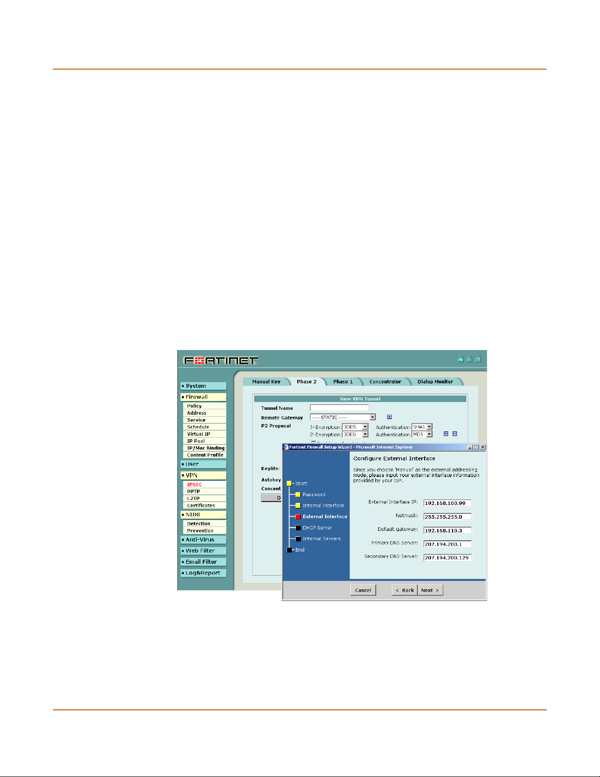
Figure 1: The FortiGate web-based manager and setup wizard
20 Fortinet Inc.
Page 21

Introduction Document conventions
Command line interface
You can access the FortiGate command line interface (CLI) by connecting a
management computer serial port to the FortiGate RS-232 serial console connector.
You can also use Telnet or a secure SSH connection to connect to the CLI from any
network that is connected to the FortiGate unit, including the Internet.
The CLI supports the same configuration and monitoring functionality as the
web-based manager. In addition, you can use the CLI for advanced configuration
options that are not available from the web-based manager.
This Installation and Configuration Guide contains information about basic and
advanced CLI commands. For a more complete description about connecting to and
using the FortiGate CLI, see the FortiGate CLI Reference Guide.
Logging and reporting
The FortiGate unit supports logging for various categories of traffic and configuration
changes. You can configure logging to:
• report traffic that connects to the firewall,
• report network services used,
• report traffic that was permitted by firewall policies,
• report traffic that was denied by firewall policies,
• report events such as configuration changes and other management events, IPSec
tunnel negotiation, virus detection, attacks, and web page blocking,
• report attacks detected by the NIDS,
• send alert email to system administrators to report virus incidents, intrusions, and
firewall or VPN events or violations.
Logs can be sent to a remote syslog server or a WebTrends NetIQ Security Reporting
Center and Firewall Suite server using the WebTrends enhanced log format. Some
models can also save logs to an optional internal hard drive. If a hard drive is not
installed, you can configure most FortiGate units to log the most recent events and
attacks detected by the NIDS to the system memory.
Document conventions
This guide uses the following conventions to describe CLI command syntax.
• angle brackets < > to indicate variable keywords
For example:
FortiGate-4000 Installation and Configuration Guide 21
Page 22

Fortinet documentation Introduction
execute restore config <filename_str>
You enter restore config myfile.bak
<xxx_str> indicates an ASCII string variable keyword.
<xxx_integer> indicates an integer variable keyword.
<xxx_ip> indicates an IP address variable keyword.
• vertical bar and curly brackets {|} to separate alternative, mutually exclusive
required keywords
For example:
set system opmode {nat | transparent}
You can enter set system opmode nat or set system opmode
transparent
• square brackets [ ] to indicate that a keyword is optional
For example:
get firewall ipmacbinding [dhcpipmac]
You can enter get firewall ipmacbinding or
get firewall ipmacbinding dhcpipmac
Fortinet documentation
Information about FortiGate products is available from the following FortiGate User
Manual volumes:
• Volume 1: FortiGate Installation and Configuration Guide
Describes installation and basic configuration for the FortiGate unit. Also describes
how to use FortiGate firewall policies to control traffic flow through the FortiGate
unit and how to use firewall policies to apply antivirus protection, web content
filtering, and email filtering to HTTP, FTP, and email content passing through the
FortiGate unit.
• Volume 2: FortiGate VPN Guide
Contains in-depth information about FortiGate IPSec VPN using certificates, preshared keys and manual keys for encryption. Also contains basic configuration
information for the Fortinet Remote VPN Client, detailed configuration information
for FortiGate PPTP and L2TP VPN, and VPN configuration examples.
• Volume 3: FortiGate Content Protection Guide
Describes how to configure antivirus protection, web content filtering, and email
filtering to protect content as it passes through the FortiGate unit.
22 Fortinet Inc.
Page 23

Introduction Customer service and technical support
• Volume 4: FortiGate NIDS Guide
Describes how to configure the FortiGate NIDS to detect and protect the FortiGate
unit from network-based attacks.
• Volume 5: FortiGate Logging and Message Reference Guide
Describes how to configure FortiGate logging and alert email. Also contains the
FortiGate log message reference.
• Volume 6: FortiGate CLI Reference Guide
Describes the FortiGate CLI and contains a reference to all FortiGate CLI
commands.
The FortiGate online help also contains procedures for using the FortiGate web-based
manager to configure and manage the FortiGate unit.
Comments on Fortinet technical documentation
You can send information about errors or omissions in this document, or any Fortinet
technical documentation, to techdoc@fortinet.com.
Customer service and technical support
For antivirus and attack definition updates, firmware updates, updated product
documentation, technical support information, and other resources, please visit the
Fortinet technical support web site at http://support.fortinet.com.
You can also register FortiGate Antivirus Firewalls from http://support.fortinet.com and
change your registration information at any time.
Fortinet email support is available from the following addresses:
amer_support@fortinet.com For customers in the United States, Canada, Mexico, Latin
apac_support@fortinet.com For customers in Japan, Korea, China, Hong Kong, Singapore,
eu_support@fortinet.com For customers in the United Kingdom, Scandinavia, Mainland
For information on Fortinet telephone support, see http://support.fortinet.com.
When requesting technical support, please provide the following information:
• Your name
• Company name
•Location
• Email address
• Telephone number
• FortiGate unit serial number
• FortiGate model
• FortiGate FortiOS firmware version
• Detailed description of the problem
America and South America.
Malaysia, all other Asian countries, and Australia.
Europe, Africa, and the Middle East.
FortiGate-4000 Installation and Configuration Guide 23
Page 24

Customer service and technical support Introduction
24 Fortinet Inc.
Page 25

FortiGate-4000 Installation and Configuration Guide Version 2.50
Getting started
This chapter describes unpacking, setting up, and powering on a FortiGate-4000
Antivirus Firewall. When you have completed the procedures in this chapter, you can
proceed to one of the following:
• If you are going to operate the FortiGate unit in NAT/Route mode, go to
“NAT/Route mode installation” on page 61.
• If you are going to operate the FortiGate unit in Transparent mode, go to
“Transparent mode installation” on page 69.
• If you are going to operate two or more FortiGate units in HA mode, go to “High
availability” on page 81.
This chapter describes:
• Warnings and cautions
• Package contents
• Physical description
• Front panel features
• Rear panel features
• Installing hardware
• Turning FortiGate-4000 chassis power on and off
• Hot swapping modules
• Connecting to the web-based manager
• Connecting to the Command Line Interface (CLI)
• Factory default configuration
• Planning the FortiGate configuration
• FortiGate model maximum values matrix
• Next steps
FortiGate-4000 Installation and Configuration Guide 25
Page 26

Warnings and cautions Getting started
!
Warnings and cautions
You should be aware of the following cautions and warnings before operating the
FortiGate-4000 antivirus firewall.
Warning
Turning off all power switches may not turn off all power to the FortiGate-4000 unit.
Disconnect the FortiGate-4000 unit from its power source and from any
telecommunications links and networks before installing and removing FortiGate-4000
components or performing other maintenance tasks. Failure to do this can result in
personal injury or equipment damage. Some circuitry in the unit may continue to
operate even though all power switches are off.
The procedures in this chapter are for qualified technical personnel with experience
installing and configuring servers. Read and adhere to all warnings, cautions, and
notices in this chapter.
Caution: Electrostatic discharge (ESD) can damage FortiGate-4000 components. You should
only perform the procedures described in this chapter from an ESD workstation. If no such
station is available, you can provide some ESD protection by wearing an anti-static wrist strap
and attaching it to a metal part of the FortiGate-4000 chassis.
Package contents
The FortiGate-4000 package consists of two or more packages. One or more of the
packages contains two FortiBlade-4010 modules. Each FortiBlade-4010 module is
capable of functioning as a standalone FortiGate-4000 antivirus firewall or being part
of a FortiGate-4000 HA cluster.
The other package contains the following components:
• FortiGate-4000 chassis which includes the following components (already
• Three power cables,
• One RJ-45 to DB-9 serial cable (only the black header works with the
• One mounting rail kit,
• One FortiGate-4000 QuickStart Guide,
• One documentation CD containing Fortinet user documentation.
installed).
• One KVM switch module (front panel),
• Ten FortiGate-4000 empty slot covers (front panel),
• One management module (rear panel),
• Seven power supply modules (rear panel),
• Four cooling fan trays (rear panel),
• Two pass-through interface modules (FortiGate-4000P rear panel), or
• Two switched interface modules (FortiGate-4000S rear panel),
• One 10/100 out of band management module (rear panel).
FortiGate-4000 unit),
26 Fortinet Inc.
Page 27

Getting started Physical description
Figure 2: FortiGate-4000 package contents
FortiGate-4000P Chassis (back view)
KVM/ACCESS
PWR/KVMSTATUS
LAN 1 LAN 2
POWER ON/OFF
Physical description
The FortiGate-4000 chassis is a 4U 19-inch rack mounted steel shelf with the
following features:
• High density design accommodates up to 10 FortiBlade-4010 modules,
• Gigabit LAN interfaces,
• SFP connectors for multimode fibre optic interfaces (FortiGate-4000S),
• Built-in KVM switch module,
• Hot-swappable FortiBlade-4010 modules, power modules, and cooling fan trays,
• Redundant power modules for high reliability.
FortiGate-4000 Installation and Configuration Guide 27
Page 28

Front panel features Getting started
Table 1: FortiGate-4000 chassis
Dimensions 42.6 x 17.7 x 67.0 cm 16.78 x 6.97 x 26.40 in.
Weight Minimum: 28 kg (61 lb) (no FortiBlade-4010 modules installed)
Operating Environment Temperature: 0 to 35°C
Storage Environment Temperature: -20 to 80°C
Power dissipation Minimum: 1050 watts
Power Requirements 100 ~ 230 VAC input
Power Consumption Minimum: 1.3 KVA (3+1 redundancy)
Front panel features
physical description
(W x H x D)
Maximum: 50 kg (110 lb) when full configured.
FortiBlade-4010: 2 kg
Relative humidity: 10% to 90% (Non-condensing)
Relative humidity: 10% to 90% (Non-condensing)
Maximum: 2100 watts
AC inlet x 3
Maximum: 2.6 KVA (6+1 redundancy)
Figure 3 shows the location of the FortiGate-4000 chassis front panel components.
The front panel contains and provides access to up to 10 FortiBlade-4010 modules
and the KVM switch module.
Figure 3: FortiGate-4000 chassis front panel
KVM/ACCESS
PWR/KVMSTATUS
LAN 1 LAN 2
POWER ON/OFF
Note: Do not operate the FortiGate-4000 chassis with open slots on the front panel. For
optimum cooling performance, all front panel slots must either contain a FortiBlade-4010
module or be covered by an empty slot cover.
28 Fortinet Inc.
Page 29
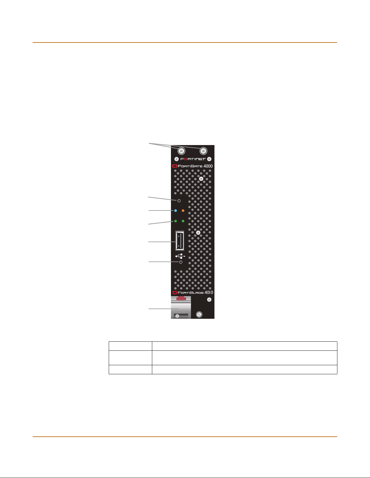
Getting started Front panel features
FortiBlade-4010 module
Each FortiBlade-4010 module is an independent FortiGate-4000 antivirus firewall
capable of operating at gigabit network speeds. You can install up to 10
FortiBlade-4010 modules in the FortiGate-4000 chassis. Each FortiBlade-4010
module can operate as a standalone FortiGate-4000 antivirus firewall or you can
group FortiBlade-4010 modules into high availability (HA) clusters. Each cluster
provides failover between the FortiBlade-4010 modules in the cluster. In addition,
when operating in active-active HA mode, the FortiBlade-4010 clusters provide
antivirus scanning load balancing to increase virus scanning performance.
Figure 4: FortiBlade-4010 front panel
Mounting Knots
KVM/ACCESS
button
PWR/KVM and
STATUS LEDs
LAN 1 and
LAN 2 LEDs
KVM/ACCESS
PWR/KVMSTATUS
LAN 1 LAN 2
Not used
Power button
POWER ON/OFF
Module lock
and handle
Table 2: FortiBlade-4010 module front panel buttons
Button Description
KVM/Access Press and hold for approximately 5 seconds for KVM access to a
FortiBlade-4010 module.
Power Power the FortiBlade-4010 module on or off.
FortiGate-4000 Installation and Configuration Guide 29
Page 30
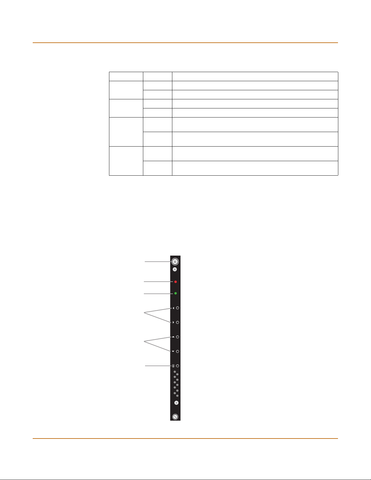
Front panel features Getting started
Table 3: FortiBlade-4010 module front panel LEDs
LED State Description
PWR/KVM Blue The FortiBlade-4010 module is powered on.
Green KVM access to this FortiBlade-4010 module is enabled.
STATUS Off Normal operation.
Red System Fault.
LAN 1 Green The correct cable is connected to the internal interface of this
FortiBlade-4010 module and the connected equipment has power.
Flashing Network activity at the internal interface of this FortiBlade-4010
module.
LAN 2 Green The correct cable is connected to the external interface of this
FortiBlade-4010 module and the connected equipment has power.
Flashing Network activity at the external interface of this FortiBlade-4010
module.
KVM switch module
Use the KVM switch module to switch serial connections to the CLI of each
FortiBlade-4010 module installed in the FortiGate-4000 chassis. To access the CLI,
connect the the black header of the RJ-45 to DB-9 serial cable to the management
module (see “Management module” on page 33) and to a management PC. You can
use the FortiBlade select buttons on the KVM switch module to select the FortiBlade4010 module that you can connect to.
Figure 5: KVM switch module front panel
Mounting Knot
ALARM
KVM
FortiBlade
select buttons
Not used
Not used
ALARM
KVM
30 Fortinet Inc.
Page 31

Getting started Rear panel features
Table 4: KVM switch module front panel buttons
Button Description
FortiBlade select buttons Use these buttons to switch console access to each
FortiBlade-4010 module.
Table 5: KVM switch module front panel LEDs
LED State Description
ALARM Off Normal operation.
Red FortiGate-4000
unit power fault resulting from a failed power supply.
KVM Green KVM switch module is powered on.
Rear panel features
The FortiGate-4000 chassis rear panel contains and provides access to 4 cooling fan
trays, 7 power supply modules, 3 power supply connectors, the management module,
and the 10/100 out of band management module. The rear panel also contains:
• The internal and external ethernet pass-through interface modules
(FortiGate-4000P),
• The internal and external ethernet switched interface modules (FortiGate-4000S).
Figure 6: FortiGate-4000P rear panel
LAN 9LAN 10 LAN 8 LAN 7 LAN 6 LAN 5 LAN 4 LAN 3 LAN 2 LAN 1 LAN 9LAN 10 LAN 8 LAN 7 LAN 6 LAN 5 LAN 4 LAN 3 LAN 2 LAN 1
LAN 2LAN 1
FortiGate-4000 Installation and Configuration Guide 31
Page 32

Rear panel features Getting started
Figure 7: FortiGate-4000S rear panel
ONON OFFOFF
LAN 2LAN 1
Power supplies and power connections
The FortiGate-4000 chassis contains 7 power supply modules. Each power supply
can provide a maximum of 350 watts for a total of 2100 watts, in 6+1 hot-swap
redundant configuration that includes load balancing. The voltage range is 100-230
Vac auto range.
The power connections supply AC power to the power supplies. Connect the three
power connections to three separate power outlets. Use the power switch on the
power connector module to turn the FortiGate-4000 chassis power on and off.
A power supply module is powered on when its power on LED turns green.
Figure 8 illustrates the power supply modules and the power connectors.
Figure 8: Power supply modules and power connectors
32 Fortinet Inc.
Page 33

Getting started Rear panel features
Cooling fan trays
The FortiGate-4000 chassis is cooled using four hot swappable cooling fan trays.
Each tray includes one 10-cm ball bearing fan unit.
Figure 9 illustrates a cooling fan tray.
Figure 9: Cooling fan tray
Fan handle
Management module
Use the KVM switch module to switch serial connections to the CLI of each
FortiBlade-4010 module installed in the FortiGate-4000 chassis. To access the CLI,
connect the black header of the RJ-45 to DB-9 serial cable to the management
module and to a management PC. You can use the FortiBlade select buttons on the
KVM switch module (see “KVM switch module” on page 30) to select the FortiBlade4010 module that you can connect to.
Figure 10: Management module
Mounting Knot
On/Off switch
ID dial
ERR LED
Not used
Console
port
Mounting Knot
ERRERR
ONON OFFOFF
Not used
FortiGate-4000 Installation and Configuration Guide 33
Page 34

Rear panel features Getting started
Table 6: Management module controls
Button Description
On/Off switch Turns the management module on and off. The management
ID dial Set to 0.
Console port Serial connection to the CLI of each FortiBlade-4010 module.
Table 7: KVM switch module LED
LED State Description
ERR Off Normal operation.
Yellow System fault. Contact Fortinet Technical Support.
module must be turned on to establish a serial connection to
the CLI of each FortiBlade-4010 module.
10/100 out of band management module
The 10/100 out of band management module provides dedicated ethernet connection
to manage each FortiBlade-4010 module installed in the FortiGate-4000 chassis. This
out of band connection is not shared by other network connections. The 10/100 out of
band management module contains two 10/100 ethernet interfaces that connect to the
management interface of each FortiBlade-4010 module.
Note: You can connect to the LAN 1 connector or to the LAN 2 connector but not both.
Figure 11: 10/100 out of band management module
LAN 2
Mounting Knot Mounting Knot
Table 8: 10/100 out of band management module LEDs
LED State Description
Interface LEDs
LAN 1
LAN 2LAN 1
Amber The correct cable is in use and the connected equipment has
Flashing
Amber
Green The interface is connected at 100 Mbps.
power.
Network activity at this interface.
34 Fortinet Inc.
Page 35

Getting started Rear panel features
Pass-through interface module
Two pass-through interface modules are installed on the FortiGate-4000P. The
internal pass-through interface module connects to each FortiBlade-4010 internal
interface. The external pass-through interface connects to each FortiBlade-4010
external interface. Each pass-through interface module contains ten gigabit copper
1000Base-T ethernet interfaces, one for each FortiBlade-4010 module.
Figure 12 shows the connections between the pass-through interface module ethernet
connectors and the FortiBlade-4010 modules installed in the FortiGate-4000 chassis.
The connections are arranged the same on the internal and external pass-through
interface modules.
Figure 12: Pass-through interface module showing interface correspondence
KVM/ACCESS
KVM/ACCESS
PWR/KVMSTATUS
PWR/KVMSTATUS
LAN 1 LAN 2
LAN 1 LAN 2
POWER ON/OFF
POWER ON/OFF
Table 9: Pass-through interface module LEDs
LED State Description
Amber The correct cable is in use and the connected equipment has
power.
Interface LEDs
Flashing
Network activity at this interface.
Amber
Green The interface is connected at up to 1000 Mbps.
Switched interface module
Two switched interface modules are installed on the FortiGate-4000S. Each switched
interface module contains two gigabit copper ethernet connectors. You can also
purchase and install optical connectors into the switched interface module small form
factor pluggable (SFP) interfaces. You cannot connect the copper interfaces and the
SPF interfaces at the same time.
FortiGate-4000 Installation and Configuration Guide 35
Page 36

Rear panel features Getting started
The internal switched interface module provides two gigabit connections to the
internal interfaces of the FortiBlade-4010 modules installed in the FortiGate-4000
chassis. The external switched interface module provides two gigabit connections to
the external interfaces of the FortiBlade-4010 modules installed in the FortiGate-4000
chassis. The switched interface modules act as layer 2 switches.
Figure 13: Switched interface module
LAN 1LAN 2COM
SFP
SFP
Table 10: Switched interface connectors
Connector Description
LAN1 and LAN2 10/100/1000 Mbit copper interfaces.
SFP Small form-factor pluggable (SFP) interface. You can install
ON OFF Turn the switched interface module on and off.
optical connectors into these interfaces to connect the
FortiGate-4000 unit to your optical network.
Table 11: Pass-through interface module LEDs
LED State Description
Amber The correct cable is in use and the connected equipment has
power.
Interface LEDs
Flashing
Network activity at this interface.
Amber
Green The interface is connected at up to 1000 Mbps.
Status Green System fault. Contact Fortinet technical support.
36 Fortinet Inc.
Page 37

Getting started Installing hardware
Installing hardware
This section describes how to install FortiGate-4000 hardware.
• Choosing a suitable environment
• Choosing a rack
• Attaching the mounting rail
• Installing FortiBlade-4010 modules
• FortiGate-4000P network connections
• FortiGate-4000S network connections
• Out of band management connections
• Console management connections
Choosing a suitable environment
Considering the following factors when selecting a suitable location for the
FortiGate-4000 unit:
• Install the FortiGate-4000 chassis on a flat, stable surface or in a suitable rack.
• Avoid a location that is exposed to strong vibration.
• Install the FortiGate-4000 chassis away from electromagnetic or radio frequency
interference.
• Avoid using or storing the FortiGate-4000 chassis where it can be exposed to
extreme temperatures. Do not leave the server in direct sunlight or near a heat
source for a long period. High temperature can damage the circuitry.
• Avoid exposing the FortiGate-4000 chassis to high or low humidity.
Choosing a rack
Install the FortiGate-4000 chassis in a rack or cabinet with a depth of more than
700 mm, excluding the front door depth. For better heat dissipation, the rear side of
the rack cabinet should be open.
Attaching the mounting rail
You can attach a mounting rail to the FortiGate-4000 chassis so that you can slide the
chassis out from the rack for maintenance. There are 11 mounting holes on the
FortiGate-4000 chassis that match different manufacturer mounting rails. Figure 14
shows the mounting locations to install the FortiGate-4000 mounting rail. Use the
three screws included with the FortiGate-4000 mounting rail kit.
FortiGate-4000 Installation and Configuration Guide 37
Page 38

Installing hardware Getting started
Figure 14: Rail mounting locations
Installing FortiBlade-4010 modules
Install a FortiBlade-4010 module by removing a FortiGate-4000 unit slot cover and
replacing it with a FortiBlade-4010 module. Begin installing the FortiBlade-4010
modules at slot number 1 and fill the FortiGate-4000 chassis from left to right (see
Figure 3 on page 28 for slot numbering).
Note: Do not operate the FortiGate-4000 unit with open slots on the front panel. For optimum
cooling performance, all front panel slots should either contain a FortiBlade-4010 module or be
covered by an empty slot cover.
1 Loosen the two screws both at the top and bottom of the FortiGate-4000 unit’s empty
slot cover that fastens the cover to the FortiGate-4000 chassis.
2 Remove the cover from the chassis.
3 Holding the FortiBlade-4010 module by the module lock and handle, insert the
FortiBlade-4010 module into the chassis. See Figure 15.
Figure 15: Inserting the FortiBlade-4010 module into the chassis
4 Slide the FortiBlade-4010 module into the slot until the lock clicks into place.
5 Tighten the mounting knots both at the top and bottom of the front panel of the
FortiBlade-4010 module.
38 Fortinet Inc.
Page 39

Getting started Installing hardware
FortiGate-4000P network connections
Use the following steps to connect your internal and external networks to the
FortiGate-4000P pass-through interface modules that support 1000Base-T
connections. This is a general connection procedure only. For information about how
to connect the FortiGate-4000 unit for different network configurations, see “Planning
the FortiGate configuration” on page 53.
1 Connect your internal network to the internal pass-through interface module.
The internal pass-through interface module is installed on the right rear panel of the
FortiGate-4000P (see Figure 6 on page 31).
You will need one network connection for each FortiBlade-4010 module installed in
the FortiGate-4000 chassis. Each FortiBlade-4010 module is connected to a different
interface on the pass-through interface module. See Figure 12 on page 35 for the
correspondence between the slots on the FortiGate-4000 chassis and the interfaces
on the pass-through interface module.
2 Connect your external network to the external pass-through interface module.
The external pass-through interface module is installed on the left rear panel of the
FortiGate-4000P (see Figure 6 on page 31).
You will need one network connection for each FortiBlade-4010 module installed in
the FortiGate-4000 chassis. Each FortiBlade-4010 module is connected to a different
interface on the pass-through interface module. See Figure 12 on page 35 for the
correspondence between the slots on the FortiGate-4000 chassis and the interfaces
on the pass-through interface module.
FortiGate-4000S network connections
Use the following steps to connect your internal and external networks to the
FortiGate-4000S switched interface modules that support 10/100/1000Base-T
connections. This is a general connection procedure only. For information about how
to connect the FortiGate-4000 unit for different network configurations, see “Planning
the FortiGate configuration” on page 53.
1 Connect your internal network to the internal switched interface module.
The internal switched interface module is installed on the right rear panel of the
FortiGate-4000S (see Figure 7 on page 32).
You can connect to the copper gigabit ethernet interfaces or to optical connectors
installed in the SFP interfaces. See Figure 13 on page 36 for the location of the
copper gigabit and SFP connectors.
2 Connect your external network to the external switched interface module.
The external switched interface module is installed on the left rear panel of the
FortiGate-4000S chassis (see Figure 7 on page 32).
FortiGate-4000 Installation and Configuration Guide 39
Page 40

Turning FortiGate-4000 chassis power on and off Getting started
Out of band management connections
You can manage the FortiBlade-4010 modules by connecting to the 10/100 out of
band management module. The 10/100 out of band management module provides
ethernet management connections for all of the FortiBlade-4010 modules installed in
the FortiGate-4000 chassis. See Figure 6 on page 31 or Figure 7 on page 32 for the
location of the 10/100 out of band management module.
Note: All FortiBlade-4010 modules are shipped with the same default IP address (172.16.1.2).
You need to change the IP address before trying to manage the modules.
Console management connections
You can connect to the CLI of each FortiBlade-4010 module by connecting the RJ-45
to DB-9 serial cable to the management module console port (see Figure 10 on
page 33). The management module provides console connections for all of the
FortiBlade-4010 modules installed in the FortiGate-4000 chassis.
Use the KVM switch module to switch serial connections to the CLI of each
FortiBlade-4010 module installed in the FortiGate-4000 chassis. To access the CLI,
connect the black header of the RJ-45 to DB-9 serial cable to the management
module (see “Management module” on page 33) and to a management PC. You can
use the KVM switch module (see “KVM switch module” on page 30) to select the
FortiBlade-4010 module that you can connect to.
Turning FortiGate-4000 chassis power on and off
Use the following procedures when turning on and off power to the FortiGate-4000
chassis. Turn power on and power off in the order specified in the following
procedures to avoid damaging FortiGate-4000 chassis components.
• Turning on FortiGate-4000 chassis power
• Turning off FortiGate-4000 chassis power
The FortiGate-4000 chassis automatically recovers from a power outage. When the
power restores, the FortiGate-4000 chassis takes a few seconds to power on. A few
seconds after the chassis is on, the FortiBlade-4010 modules power on automatically.
Turning on FortiGate-4000 chassis power
Turning on the FortiGate-4000 chassis power consists of making power connections,
turning on power supplies, and then turning on individual components.
1 Make sure all FortiGate-4000 chassis power switches are turned off.
Check the following:
• Power switch on each power supply module
• Chassis power switch on the power connector module
• On/off switch on the management module
• On/off switch on the switched interface module (FortiGate-4000S)
40 Fortinet Inc.
Page 41

Getting started Hot swapping modules
2 Connect the three power cables to the power connection module on the
FortiGate-4000 chassis back panel.
3 Connect the power cables to power outlets.
4 Turn on the power switch on each power supply module.
5 Press and hold the chassis power switch for a few seconds to turn it on to supply
power to the power supplies.
The Power LED on each power supply module lights.
6 Turn on the management module power switch.
7 Turn on the switched interface module power switch for each switched interface
module (FortiGate-4000S).
8 Press and hold the power button on each FortiBlade-4010 module for a few seconds.
The PWR LED on each FortiBlade-4010 module lights.
Turning off FortiGate-4000 chassis power
Turning off the FortiGate-4000 chassis power in the reverse order from turning power
on.
Note: Always wait at least five seconds after turning off FortiGate-4000 chassis power before
turning it back on. Turning the power on and off in rapid succession can damage
FortiGate-4000 electrical circuitry.
1 Press the power button on each FortiBlade-4010 module.
The PWR LED on each FortiBlade-4010 module goes out.
2 Turn off the switched interface module power switch for each switched interface
module (FortiGate-4000S).
3 Turn off the management module power switch.
4 Turn off the chassis power switch.
5 Turn off the power switch on each power supply module.
Hot swapping modules
This section describes how to hot swap the modules installed in the FortiGate-4000
chassis. Hot swapping refers to removing a failed module and replacing it with a new
version of the same module while the FortiGate-4000 chassis remains in operation.
This section describes:
• Hot swapping FortiBlade-4010 modules
• Hot swapping cooling fan trays
• Hot swapping power supplies
• Hot swapping interface modules
• Hot swapping the 10/100 out of band management module
• Hot swapping the management module
• Hot swapping the KVM switch module
FortiGate-4000 Installation and Configuration Guide 41
Page 42

Hot swapping modules Getting started
Hot swapping FortiBlade-4010 modules
Follow this procedure to hot swap the FortiBlade-4010 modules. For information about
the FortiBlade-4010 module, see “FortiBlade-4010 module” on page 29.
1 Press the power button on the front panel of the FortiBlade-4010 module that you
want to replace.
The PWR LED on the FortiBlade-4010 module goes out.
Note: Wait at least five seconds after turning off the power before removing the FortiBlade-4010
module from the chassis.
2 Loosen the two mounting knots that fasten the module system tray to the
FortiGate-4000 chassis. Do not remove the mounting knots.
3 Holding the FortiBlade-4010 module by the module lock and handle, slide it out of the
chassis.
4 Holding the new FortiBlade-4010 module by the module lock and handle, insert it into
the chassis.
5 Slide the FortiBlade-4010 module into the slot until the lock clicks into place.
6 Tighten the mounting knots on the top of the front panel of the FortiBlade-4010
module.
7 Press the power button on the FortiBlade-4010 module.
The PWR LED on the FortiBlade-4010 module lights.
Hot swapping cooling fan trays
Each FortiGate-4000 unit has four cooling fan trays. See “Cooling fan trays” on
page 33 for more information.
Follow this procedure to hot swap a cooling fan tray.
1 From the rear panel of the FortiGate-4000 chassis, pull out the cooling fan tray you
want to replace by the handle.
2 Holding the new fan tray by the handle, insert it into the chassis.
Hot swapping power supplies
The FortiGate-4000 power supply modules are secured to the chassis by a locking
handle and a locking strip located at the bottom of the modules. For more information,
see “Rear panel features” on page 31.
Follow this procedure to hot swap a power supply module.
1 On the power supply module that you want to replace, turn off the power supply.
2 From the rear panel of the FortiGate-4000 chassis, unscrew the two locking screws
that fasten the locking strip of the power supply modules. See Figure 8 on page 32.
3 Remove the locking strip.
4 Lift up the locking handle of the power supply to be removed.
5 Pull out the power supply module by the handle.
6 Holding the new power supply module by the handle, insert it into the chassis.
42 Fortinet Inc.
Page 43

Getting started Hot swapping modules
7 Slide the power supply module into the slot until the lock clicks into place.
8 Turn on the power supply.
9 Replace the locking strip.
10 Quickly toggle the chassis power supply switch to turn on the power supply module.
Note: If you press the chassis power supply switch for more than four seconds, the entire
FortiGate-4000 unit turns off.
Hot swapping interface modules
This procedure describes how to hot swap a pass-through interface module or a
switched interface module.
For more information on these modules, see “Pass-through interface module” on
page 35 and “Switched interface module” on page 35 respectively.
1 From the rear panel of the FortiGate-4000 chassis, loosen the two mounting knots that
fasten the pass-through interface module or the switched interface module that you
want to replace. Do not remove the mounting knots.
2 Do one of the following:
• For the pass-through interface module, pull it out.
• For the switched interface module, turn its power off and then pull it out.
3 Do one of the following:
• Insert the new pass-through interface module into the chassis.
• Insert the new switched interface module into the chassis, and turn on its power.
4 Tighten the mounting knots on the pass-through interface module or the switched
interface module.
Hot swapping the 10/100 out of band management module
Follow this procedure to hot swap a 10/100 out of band management module on the
rear panel of the FortiGate-4000 chassis.
For more information, see “10/100 out of band management module” on page 34.
1 From the rear panel of the FortiGate-4000 chassis, loosen the two mounting knots that
fasten the 10/100 out of band management that you want to replace. Do not remove
the mounting knots.
2 Pull the module out.
3 Insert the new switched interface module into the chassis.
4 Tighten the mounting knots on the module.
Hot swapping the management module
Follow this procedure to hot swap a management module on the rear panel of the
FortiGate-4000 chassis.
For more information on these modules, see “Management module” on page 33.
1 Power off the management module that you want to replace.
FortiGate-4000 Installation and Configuration Guide 43
Page 44

Connecting to the web-based manager Getting started
2 Unscrew the two locking screws to remove the module’s locking strip.
3 Loosen its two mounting knots. Do not remove the mounting knots.
4 Pull out the management module.
5 Insert the new management module into the chassis.
6 Slide the management module into the slot until the lock clicks into place.
7 Screw the locking screws to fasten the locking strip.
8 Tighten the two mounting knots.
9 Turn on the power of the management module.
Hot swapping the KVM switch module
Follow this procedure to hot swap a KVM switch module.
For more information on the KVM switch module, see “KVM switch module” on
page 30.
1 From the front panel of the FortiGate-4000 chassis, loosen the two mounting knots
that fasten the KVM switch module that you want to replace.
2 Pull out the KVM switch module.
3 Insert the new KVM switch module into the chassis.
4 Tighten the two mounting knots to fasten the KVM switch module to the chassis.
Connecting to the web-based manager
You can connect to the FortiGate-4000 web-based manager of each FortiGate-4000
unit installed in the FortiGate-4000 chassis by connecting to FortiGate-4000 internal
interface module or by connecting to the FortiGate-4000 10/100 out of band
management module.
Note: Each FortiBlade-4010 module is a FortiGate-4000 antivirus firewall.
To connect to the web-based manager you need:
• an ethernet connection between a management computer and the FortiGate-4000
unit.
• Internet Explorer version 4.0 or higher running on the management computer.
Note: You can use the web-based manager with recent versions of most popular web browsers.
The web-based manager is fully supported for Internet Explorer version 4.0 or higher.
• Connecting to the FortiGate-4000 internal interface module
• Connecting to the FortiGate-4000 10/100 out of band management module
• Connecting to the Command Line Interface (CLI)
44 Fortinet Inc.
Page 45

Getting started Connecting to the web-based manager
Connecting to the FortiGate-4000 internal interface module
To connect to the web-based manager of a FortiGate-4000 unit using the FortiGate4000 internal interface module, you must connect the FortiGate-4000 internal
interface module to the same network as your management computer.
To connect to the web-based manager
1 Connect the internal interface module to your network.
• For the FortiGate-4000P, each FortiGate-4000 unit is connected to a different
connector on the internal interface pass-through interface module. See Figure 6 on
page 31 for the location of the internal interface pass-through module. See
Figure 12 on page 35 for the correspondence between each pass-through
interface connector and each FortiGate-4000 unit .
• For the location of the FortiGate-4000 unit internal interface connections for the
FortiGate-4000S, see Figure 7 on page 32.
2 Power on the FortiGate-4000 unit that you want to connect to.
Note: When first installed, all FortiGate-4000 units installed in the FortiGate-4000 chassis have
the same internal, external, and out of band management IP addresses. To connect to a
specific FortiGate-4000 unit, you must turn on the power for this FortiGate-4000 unit. The power
to all of the other FortiGate-4000 units must be turned off.
Alternatively, you can use the CLI to change the default internal IP address of a specific
FortiGate-4000 unit to which you want to connect. This way, you do not need to power off all of
the other FortiGate-4000 units when connecting to that specific FortiGate-4000 unit.
3 Set the IP address of the management computer with an ethernet connection to the
static IP address 192.168.1.2 and a netmask of 255.255.255.0.
4 Start Internet Explorer and browse to the address https://192.168.1.99 (remember to
include the “s” in https://).
The FortiGate login is displayed.
5 Type admin in the Name field and select Login.
The Register Now window is displayed. Use the information in this window to register
your FortiGate unit so that Fortinet can contact you for firmware updates. You must
also register to receive updates to the FortiGate virus and attack definitions.
FortiGate-4000 Installation and Configuration Guide 45
Page 46

Connecting to the web-based manager Getting started
Figure 16: FortiGate login
Connecting to the FortiGate-4000 10/100 out of band management module
To connect to the web-based manager of a FortiGate-4000 unit using the
FortiGate-4000 10/100 out of band management module, you must connect the out of
band management module to the same network as your management computer.
For more information about the 10/100 out of band management module, see “10/100
out of band management module” on page 34 and “Out of band management
connections” on page 40.
To connect to the 10/100 out of band management module
1 Connect the 10/100 out of band management module to your network.
2 Power on the FortiGate-4000 unit that you want to connect to.
Note: When first installed, all FortiGate-4000 units installed in the FortiGate-4000 chassis have
the same internal, external, and out of band management IP addresses. To connect to a
specific FortiGate-4000 unit
power to all of the other FortiGate-4000 units must be turned off.
, you must turn on the power for this FortiGate-4000 unit. The
3 Set the IP address of the computer with an ethernet connection to the static IP
address 172.16.1.3 and a netmask of 255.255.255.0.
4 Start Internet Explorer and browse to the address https://172.16.1.2 (remember to
include the “s” in https://).
The FortiGate login is displayed.
5 Type admin in the Name field and select Login.
The Register Now window is displayed. Use the information in this window to register
your FortiGate unit so that Fortinet can contact you for firmware updates. You must
also register to receive updates to the FortiGate virus and attack definitions.
46 Fortinet Inc.
Page 47

Getting started Connecting to the Command Line Interface (CLI)
To change the out of band management IP address
1 After logging into the FortiGate-4000 unit, go to System > Network > OOB
Management.
2 Change the IP/Netmask addresses.
3 Select Apply to save the changes.
Connecting to the Command Line Interface (CLI)
Connect to the CLI of each FortiGate-4000 unit by connecting to the management
interface module. Use the KVM switch module to switch serial connections to the CLI
of each FortiGate-4000 unit installed in the FortiGate-4000 chassis. See Figure 5 on
page 30 for the description of the KVM switch module.
To connect to the CLI of each FortiGate-4000 unit , you need:
• a computer with an available communications port,
• a RJ-45 to DB-9 cable included in your FortiGate package,
• terminal emulation software such as HyperTerminal for Windows.
Note: The following procedure describes how to connect to the CLI using Windows
HyperTerminal software. You can use any terminal emulation program.
To connect to the CLI of each FortiGate-4000 unit
1 Connect the black header of the RJ-45 to DB-9 cable to the communications port of
your computer and to the management module console port.
2 Make sure that the FortiGate-4000 unit is powered on.
3 Use the KVM select buttons on the KVM switch module to select the FortiGate-4000
unit that you want to connect to.
4 On the front panel of the FortiGate-4000 unit you select, press and hold the
KVM/Access button for approximately 5 seconds for CLI access to the module.
The PWR/KVM LED turns green, and CLI access to the module is enabled.
5 Start HyperTerminal on your management computer, enter a name for the connection,
and select OK.
6 Configure HyperTerminal to connect directly to the communications port on the
computer to which you have connected the RJ-45 to DB-9 cable and select OK.
7 Select the following port settings and select OK.
Bits per second 9600
Data bits 8
Parity None
Stop bits 1
Flow control None
FortiGate-4000 Installation and Configuration Guide 47
Page 48

Factory default configuration Getting started
8 Press Enter to connect to the CLI of the FortiGate-4000 unit.
The following prompt is displayed:
FortiGate-4000 login:
9 Type admin and press Enter twice.
The following prompt is displayed:
Type ? for a list of commands.
For information about how to use the CLI, see the FortiGate CLI Reference Guide.
Factory default configuration
Each FortiGate-4000 unit in a FortiGate-4000 chassis is shipped with a factory default
configuration. The default configuration allows you to connect to and use the
FortiGate web-based manager to configure the FortiGate-4000 unit onto the network.
To configure the FortiGate-4000 unit onto the network, you add an administrator
password, change network interface IP addresses, add DNS server IP addresses, and
configure routing, if required.
If you plan to operate the FortiGate-4000 unit in Transparent mode, you can switch to
Transparent mode from the factory default configuration and then configure the
FortiGate-4000 unit onto the network in Transparent mode.
Once the network configuration is complete, you can perform additional configuration
tasks such as setting system time, configuring virus and attack definition updates, and
registering the FortiGate-4000 unit.
The factory default firewall configuration includes a single network address translation
(NAT) policy that allows users on your internal network to connect to the external
network, and stops users on the external network from connecting to the internal
network. You can add more policies to provide more control of the network traffic
passing through the FortiGate-4000 units.
The factory default content profiles can be used to apply different levels of antivirus
protection, web content filtering, and email filtering to the network traffic that is
controlled by firewall policies.
• Factory default NAT/Route mode network configuration
• Factory default Transparent mode network configuration
• Factory default firewall configuration
• Factory default content profiles
Factory default NAT/Route mode network configuration
When the FortiGate-4000 unit is first powered on, it is running in NAT/Route mode and
has the basic network configuration listed in Tab le 1 2. This configuration allows you to
connect to the FortiGate-4000 unit web-based manager and establish the
configuration required to connect the FortiGate-4000 unit to the network. In Ta b le 1 2,
HTTPS management access means you can connect to the web-based manager
using this interface. Ping management access means this interface responds to ping
requests.
48 Fortinet Inc.
Page 49

Page 50

Factory default configuration Getting started
Table 14: Factory default firewall configuration
Internal
Address
External
Address
Recurring
Schedule
Firewall
Policy
Internal_All
External_All
Always The schedule is valid at all times. This means that
Internal->External Firewall policy for connections from the internal
Source Internal_All The policy source address. Internal_All means that
Destination External_All The policy destination address. External_All means
Schedule Always The policy schedule. Always means that the policy
Service ANY The policy service. ANY means that this policy
Action ACCEPT The policy action. ACCEPT means that the policy
; NAT NAT is selected for the NAT/Route mode default
Traffic Shaping Traffic shaping is not selected. The policy does not
Authentication Authentication is not selected. Users do not have to
; Antivirus & Web Filter Antivirus & Web Filter is selected.
Content
Profile
Log Traffic Log Traffic is not selected. This policy does not
IP: 0.0.0.0 Represents all of the IP addresses on the internal
Mask: 0.0.0.0
IP: 0.0.0.0 Represents all of the IP addresses on the external
Mask: 0.0.0.0
Scan The scan content profile is selected. The policy
network.
network.
the firewall policy is valid at all times.
network to the external network.
the policy accepts connections from any internal IP
address.
that the policy accepts connections with a
destination address to any IP address on the
external network.
is valid at any time.
processes connections for all services.
allows connections.
policy so that the policy applies network address
translation to the traffic processed by the policy.
NAT is not available for Transparent mode policies.
apply traffic shaping to the traffic controlled by the
policy. You can select this option to control the
maximum or minimum amount of bandwidth
available to traffic processed by the policy.
authenticate with the firewall before connecting to
their destination address. You can configure user
groups and select this option to require users to
authenticate with the firewall before they can
connect through the firewall.
scans all HTTP, FTP, SMTP, POP3, and IMAP
traffic for viruses. See “Scan content profile” on
page 51 for more information about the scan
content profile. You can select one of the other
content profiles to apply different levels of content
protection to traffic processed by this policy.
record messages to the traffic log for the traffic
processed by this policy. You can configure
FortiGate logging and select Log Traffic to record all
connections through the firewall that are accepted
by this policy.
50 Fortinet Inc.
Page 51

Getting started Factory default configuration
Factory default content profiles
You can use content profiles to apply different protection settings for content traffic
that is controlled by firewall policies. You can use content profiles for:
• Antivirus protection of HTTP, FTP, IMAP, POP3, and SMTP network traffic
• Web content filtering for HTTP network traffic
• Email filtering for IMAP and POP3 network traffic
• Oversized file and email blocking for HTTP, FTP, POP3, SMTP, and IMAP network
traffic
• Passing fragmented emails in IMAP, POP3, and SMTP email traffic
Using content profiles, you can build protection configurations that can be applied to
different types of firewall policies. This allows you to customize types and levels of
protection for different firewall policies.
For example, while traffic between internal and external addresses might need strict
protection, traffic between trusted internal addresses might need moderate protection.
You can configure policies for different traffic services to use the same or different
content profiles.
Content profiles can be added to NAT/Route mode and Transparent mode policies.
Strict content profile
Use the strict content profile to apply maximum content protection to HTTP, FTP,
IMAP, POP3, and SMTP content traffic. You do not need to use the strict content
profile under normal circumstances, but it is available if you have extreme problems
with viruses and require maximum content screening protection.
Table 15: Strict content profile
Options HTTP FTP IMAP POP3 SMTP
Antivirus Scan ;;;;;
File Block ;;;;;
Web URL Block ;
Web Content Block ;
Web Script Filter ;
Web Exempt List ;
Email Block List ;;
Email Exempt List ;;
Email Content Block ;;
Oversized File/Email Block block block block block block
Pass Fragmented Emails
Scan content profile
Use the scan content profile to apply antivirus scanning to HTTP, FTP, IMAP, POP3,
and SMTP content traffic.
FortiGate-4000 Installation and Configuration Guide 51
Page 52

Factory default configuration Getting started
Table 16: Scan content profile
Web content profile
Use the web content profile to apply antivirus scanning and web content blocking to
HTTP content traffic. You can add this content profile to firewall policies that control
HTTP traffic.
52 Fortinet Inc.
Page 53

Getting started Planning the FortiGate configuration
Unfiltered content profile
Use the unfiltered content profile if you do not want to apply content protection to
traffic. You can add this content profile to firewall policies for connections between
highly trusted or highly secure networks where content does not need to be protected.
Planning the FortiGate configuration
Before you configure the FortiGate-4000 units in the FortiGate-4000 chassis, you
need to plan how to integrate them into your network. Among other things, you must
decide whether you want the FortiGate-4000 units to be visible to the network, which
firewall functions you want to provide, and how you want it to control the traffic flowing
between FortiGate-4000 unit interfaces.
This section contains overviews for installing a FortiGate-4000 unit with the following
configurations:
• NAT/Route mode standalone configuration
• Transparent mode standalone configuration
• FortiGate-4000 HA configuration
• FortiGate-4000P units with external load balancers
NAT/Route mode standalone configuration
FortiGate-4000 Installation and Configuration Guide 53
Page 54

Planning the FortiGate configuration Getting started
For each FortiGate-4000 unit, the following interfaces are available for processing
network traffic in NAT/Route mode:
• External: the interface to the external network (usually the Internet).
• Internal: the interface to the internal network.
In addition, the 10/100 out of band management interface is available for out of band
management. The out of band management IP address must not be on the same
subnet as the internal or external interfaces.
You can add security policies to control whether communications through the
FortiGate-4000 unit operate in NAT or Route mode. Security policies control the flow
of traffic based on the source address, destination address, and service of each
packet. In NAT mode, the FortiGate-4000 unit performs network address translation
before it sends the packet to the destination network. In Route mode, there is no
translation.
By default, the FortiGate-4000 unit has a NAT mode security policy that allows users
on the internal network to securely download content from the external network. No
other traffic is possible until you have configured further security policies.
You typically use NAT/Route mode when the FortiGate-4000 unit is operating as a
gateway between private and public networks. In this configuration, you would create
NAT mode policies to control traffic flowing between the internal, private network and
the external, public network (usually the Internet).
Figure 17: Example NAT/Route mode standalone network configuration
External
204.23.1.5
NAT mode policies controlling
traffic between internal and
external networks.
Transparent mode standalone configuration
In Transparent mode standalone configuration, each FortiGate-4000 unit in the
FortiGate-4000 chassis operates as a separate Transparent mode FortiGate-4000
antivirus firewall. Each of these FortiGate-4000 unit is invisible to the network. Similar
to a network bridge, the FortiGate internal and external interfaces must be on the
same subnet. You only have to configure a management IP address so that you can
make configuration changes. The management IP address is also used for antivirus
and attack definition updates.
In addition, the 10/100 out of band management interface is available for out of band
management. The out of band management IP address must not be on the same
subnet as the management IP address.
Internal network
192.168.1.3
54 Fortinet Inc.
Page 55

Getting started Planning the FortiGate configuration
You typically use a FortiGate-4000 unit in Transparent mode on a private network
behind an existing firewall or behind a router. The FortiGate-4000 unit performs
firewall functions as well as antivirus and content scanning but not VPN.
The following interfaces are available in Transparent mode:
• External: the interface to the external network (usually the Internet).
• Internal: the interface to the internal network.
Figure 18: Example Transparent mode standalone network configuration
FortiGate-4000 unit
in Transparent mode
Internet
Gateway to
public newtwork
204.23.1.5
(Firewall, router)
192.168.1.1
External
192.168.1.2
Management IP
Transparent mode policies controlling
traffic between internal and
external networks.
KVM/ACCESS
PWR/KVMSTATUS
LAN 1 LAN 2
POWER ON/OFF
Internal
Internal network
192.168.1.3
FortiGate-4000 HA configuration
Using HA, you can group two or more FortiGate-4000 units into an HA cluster. The HA
cluster can operate in active-active mode or active-passive mode.
An active-active HA cluster can increase virus scanning throughput by using load
balancing to distribute virus scanning to all of the FortiGate units in the cluster.
An active-passive HA cluster provides failover so that if a functioning FortiGate-4000
unit fails, processing is transferred to another FortiGate-4000 unit in the cluster
without interrupting network service.
Once the FortiGate-4000 units are added to the HA cluster, the cluster functions on
your network as a single FortiGate-4000 unit with one internal interface, one external
interface, and one out of band management IP address. The cluster manages
communication and load balancing between the FortiGate-4000 units in the cluster.
Because you can install up to 10 FortiGate-4000 units in a single FortiGate-4000
chassis, you can configure multiple HA clusters. Each FortiGate-4000 unit can only
belong to one cluster.
You can operate an HA cluster in NAT/Route or Transparent mode. A single
FortiGate-4000 chassis can contain clusters operating in NAT/Route mode and
clusters operating in Transparent mode. For more information on HA, see “High
availability” on page 81.
FortiGate-4000 Installation and Configuration Guide 55
Page 56

Planning the FortiGate configuration Getting started
Figure 19: HA network configuration in NAT/Route mode
Internet
External
204.23.1.5
KVM/ACCESS
KVM/ACCESS
PWR/KVMSTATUS
PWR/KVMSTATUS
LAN 1LAN 2
LAN 1LAN 2
POWER ON/OFF
POWER ON/OFF
NAT mode policies controlling
traffic between internal and
external networks.
Figure 20: HA network configuration in Transparent mode
FortiGate-4000P HA configuration
In the FortiGate-4000P HA configuration, you connect your internal pass-through
interface module to a switch or hub connected to the internal network, and your
external pass-through interface module to a switch or hub connected to the external
network. See Figure 21.
56 Fortinet Inc.
Page 57

Getting started Planning the FortiGate configuration
Figure 21: FortiGate-4000P HA configuration
FortiGate-4000P HA cluster
123
KVM/ACCESS
KVM/ACCESS
PWR/KVMSTATUS
PWR/KVMSTATUS
LAN 1LAN 2
LAN 1LAN 2
POWER ON/OFF
POWER ON/OFF
KVM ACCESS
PWR/KVMSTATUS
LAN 1LAN 2
POWER ON/OFF
ALARM
KVM
External
192.168.1.1
Hub or Switch
Internal
192.168.1.99
Hub or switch
192.168.1.3
Internal Network
FortiGate-4000S HA configuration
In the FortiGate-4000S HA configuration, all you need to do is to connect your internal
network to the internal switched interface module and your external network to the
external switched interface module. You do not need to connect to external switches
because the switched interface module acts as the switch.
FortiGate-4000P units with external load balancers
The FortiGate-4000P unit can use external load balancers to load balance the virus
scanning among all the FortiGate-4000P units in the cluster. Load balancers increase
the network’s overall security performance by distributing traffic across multiple
FortiGate units.
Each FortiGate unit connects directly to the load balancers to load balance internal
and external traffic.
With external load balancers, all FortiGate-4000P units in the cluster need to be
standalone and operate in NAT/Route mode.
204.23.1.5
Internet
FortiGate-4000 Installation and Configuration Guide 57
Page 58

Planning the FortiGate configuration Getting started
Figure 22: FortiGate-4000P configuration with load balancers
FortiGate-4000 Unit
Internal
Internal Network
58 Fortinet Inc.
Page 59

Getting started FortiGate model maximum values matrix
FortiGate model maximum values matrix
Table 19: FortiGate maximum values matrix
FortiGate model
50 60 100 200 300 400 500 800 1000 3000 3600 4000
Routes 500 500 500 500 500 500 500 500 500 500 500 500
Policy routing
gateways
Administrative
users
VLAN
subinterfaces
Zones N/A N/A N/A 100 100 100 100 100 200 300 500 500
Virtual domains N/AN/AN/A1632646464128512512512
DHCP address
scopes
DHCP reserved
IP/MAC pairs
Firewall policies 200 500 1000 2000 5000 5000 20000 20000 50000 50000 50000 50000
Firewall
addresses
Firewall address
groups
Firewall custom
services
Firewall service
groups
Firewall recurring
schedules
Firewall onetime
schedules
Firewall virtual
IPs
Firewall IP pools 50 50 50 50 50 50 50 50 50 50 50 50
IP/MAC binding
table entries
Firewall content
profiles
User names 20 500 1000 1000 1000 1000 1000 1000 1000 1000 1000 1000
Radius servers 666666666666
LDAP servers 666666666666
User groups 100 100 100 100 100 100 100 100 100 100 100 100
Tota l n u m b e r o f
user group
members
* Includes the number of physical interfaces.
500 500 500 500 500 500 500 500 500 500 500 500
500 500 500 500 500 500 500 500 500 500 500 500
N/A N/A N/A 4096* 4096* 4096* 4096* 4096* 4096* 4096* 4096* 4096*
32 32 32 32 32 32 32 32 32 32 32 32
10 20 30 30 50 50 100 100 200 200 200 200
500 500 500 500 3000 3000 6000 6000 10000 10000 10000 10000
500 500 500 500 500 500 500 500 500 500 500 500
500 500 500 500 500 500 500 500 500 500 500 500
500 500 500 500 500 500 500 500 500 500 500 500
256 256 256 256 256 256 256 256 256 256 256 256
256 256 256 256 256 256 256 256 256 256 256 256
500 500 500 500 500 500 500 500 500 500 500 500
500 500 500 500 500 500 500 500 500 500 500 500
32 32 32 32 32 32 32 32 32 32 32 32
300 300 300 300 300 300 300 300 300 300 300 300
FortiGate-4000 Installation and Configuration Guide 59
Page 60

Next steps Getting started
Table 19: FortiGate maximum values matrix
FortiGate model
50 60 100 200 300 400 500 800 1000 3000 3600 4000
IPSec remote
gateways
(Phase 1)
IPSec VPN
tunnels (Phase 2)
IPSec VPN
concentrators
PPTP users 500 500 500 500 500 500 500 500 500 500 500 500
L2TP users 500 500 500 500 500 500 500 500 500 500 500 500
NIDS user-defined
signatures
Antivirus file
block patterns
Web filter and
email filter lists
Log setting traffic
filter entries
* Includes the number of physical interfaces.
20 50 80 200 1500 1500 3000 3000 5000 5000 5000 5000
20 50 80 200 1500 1500 3000 3000 5000 5000 5000 5000
500 500 500 500 500 500 500 500 500 500 500 500
100 100 100 100 100 100 100 100 100 100 100 100
56 56 56 56 56 56 56 56 56 56 56 56
Limit varies depending on available system memory. Fortinet recommends limiting total size of web and
email filter lists to 4 Mbytes or less. If you want to use larger web filter lists, consider using Cerberian web
filtering.
50 50 50 50 50 50 50 50 50 50 50 50
Next steps
Now that your FortiGate unit is operating, you can proceed to configure it to connect to
networks:
• If you are going to operate the FortiGate unit in NAT/Route mode, go to
“NAT/Route mode installation” on page 61.
• If you are going to operate the FortiGate unit in Transparent mode, go to
“Transparent mode installation” on page 69.
• If you are going to operate two or more FortiGate units in HA mode, go to “High
availability” on page 81.
60 Fortinet Inc.
Page 61

FortiGate-4000 Installation and Configuration Guide Version 2.50
NAT/Route mode installation
This chapter describes how to install the FortiGate unit in NAT/Route mode. For
information about installing a FortiGate unit in Transparent mode, see “Transparent
mode installation” on page 69. For information about installing two or more FortiGate
units in HA mode, see “High availability” on page 81. For more information about
installing the FortiGate unit in NAT/Route mode, see “Planning the FortiGate
configuration” on page 54.
This chapter describes:
• Preparing to configure NAT/Route mode
• Using the setup wizard
• Using the command line interface
• Completing the configuration
• Connecting the FortiGate unit to your networks
• Configuring your networks
• Completing the configuration
Preparing to configure NAT/Route mode
Use Tab le 20 to gather the information that you need to customize NAT/Route mode
settings.
Table 20: NAT/Route mode settings
Administrator Password:
Internal interface
FortiGate-4000 Installation and Configuration Guide 61
IP: _____._____._____._____
Netmask: _____._____._____._____
Page 62

Preparing to configure NAT/Route mode NAT/Route mode installation
Table 20: NAT/Route mode settings (Continued)
IP: _____._____._____._____
Netmask: _____._____._____._____
External interface
Internal servers
Default Gateway: _____._____._____._____
Primary DNS Server: _____._____._____._____
Secondary DNS Server: _____._____._____._____
Web Server: _____._____._____._____
SMTP Server: _____._____._____._____
POP3 Server: _____._____._____._____
IMAP Server: _____._____._____._____
FTP Server: _____._____._____._____
If you provide access from the Internet to a web server, mail server,
IMAP server, or FTP server installed on an internal network, add the IP
addresses of the servers here.
Advanced NAT/Route mode settings
Use Tab le 21 to gather the information that you need to customize advanced
FortiGate NAT/Route mode settings.
Table 21: Advanced FortiGate NAT/Route mode settings
DHCP:
External
interface
PPPoE:
If your Internet Service Provider (ISP) supplies you with
an IP address using DHCP, no further information is
required.
User name:
Password:
If your ISP supplies you with an IP address using PPPoE, record your
PPPoE user name and password.
Starting IP: _____._____._____._____
Ending IP: _____._____._____._____
Netmask: _____._____._____._____
DHCP server
The FortiGate unit includes a DHCP server that you can configure to
automatically set the addresses of the computers on your internal network.
Default Route: _____._____._____._____
DNS IP: _____._____._____._____
62 Fortinet Inc.
Page 63

NAT/Route mode installation Using the setup wizard
Out of band management interface
Use Tab le 22 to record the IP address, netmask, and default gateway of the
FortiGate-4000 out of band management interface if you are configuring this interface
during installation.
.
Table 22: Out of band management interface (Optional)
IP: _____._____._____._____ Netmask: _____._____._____._____
Default Gateway: _____._____._____._____
Using the setup wizard
From the web-based manager, you can use the setup wizard to complete the initial
configuration of the FortiGate unit. For information about connecting to the web-based
manager, see “Connecting to the web-based manager” on page 44.
Starting the setup wizard
1 In the web-based manager, select Easy Setup Wizard (the middle button in the upper-
right corner of the web-based manager).
2 Select the Next button to step through the wizard pages.
3 Use the information that you gathered in Table 20 on page 61 to fill in the wizard fields.
You can also use the information in Table 21 on page 62.
4 Confirm the configuration settings, and then select Finish and Close.
Note: If you use the setup wizard to configure internal server settings, the FortiGate unit adds
port forwarding virtual IPs and firewall policies for each server. For example, for each server
located on the Internal network the FortiGate unit adds an External->Internal firewall policy.
Reconnecting to the web-based manager
If you connected to the FortiGate unit using the internal interface and you changed the
IP address of the internal interface while you were using the setup wizard, you must
reconnect to the web-based manager using a new IP address. Browse to https://
followed by the new IP address of the internal interface. Otherwise, you can reconnect
to the web-based manager by browsing to https://192.168.1.99.
The IP address of the out of band management interface is not changed from the
setup wizard. If you connected to the FortiGate unit using the out of band
management interface you do not have to reconnect after completing the wizard.
You are now finished the initial configuration of your FortiGate unit, and can proceed
to “Completing the configuration” on page 66.
FortiGate-4000 Installation and Configuration Guide 63
Page 64

Using the command line interface NAT/Route mode installation
Using the command line interface
As an alternative to using the setup wizard, you can configure the FortiGate unit using
the command line interface (CLI). For information about connecting to the CLI, see
“Connecting to the Command Line Interface (CLI)” on page 47.
Configuring the FortiGate unit to operate in NAT/Route mode
Use the information that you gathered in Table 20 on page 61 to complete the
following procedure.
Configuring NAT/Route mode IP addresses
1 Make sure that you are logged into the CLI.
2 Set the IP address and netmask of the internal interface to the internal IP address and
netmask that you recorded in Table 20 on page 61. Enter:
set system interface internal mode static ip <IP_address>
<netmask>
Example
set system interface internal mode static ip 192.168.1.1
255.255.255.0
3 Set the IP address and netmask of the external interface to the external IP address
and netmask that you recorded in Table 20 on page 61.
set system interface external mode static ip <IP_address>
<netmask>
Example
set system interface external mode
255.255.255.0
To set the external interface to use DHCP, enter:
set system interface external mode dhcp connection enable
To set the external interface to use PPPoE, enter:
set system interface external mode pppoe
password
Example
set system interface external mode pppoe username
user@domain.com password mypass connection enable
<password>
connection
static
enable
ip 204.23.1.5
username
<user name>
4 Confirm that the addresses are correct. Enter:
get system interface
The CLI lists the IP address, netmask, and other settings for each of the FortiGate
interfaces.
5 Set the primary DNS server IP addresses. Enter
set system dns primary <IP address>
Example
set system dns primary 293.44.75.21
64 Fortinet Inc.
Page 65

NAT/Route mode installation Connecting the FortiGate unit to your networks
6 Optionally, set the secondary DNS server IP addresses. Enter
set system dns secondary <IP address>
Example
set system dns secondary 293.44.75.22
7 Set the default route to the Default Gateway IP address (not required for DHCP and
PPPoE).
set system route number <route_no> dst 0.0.0.0 0.0.0.0 gw1
<gateway_ip>
Example
set system route number 0 dst 0.0.0.0 0.0.0.0 gw1 204.23.1.2
Configuring the out of band management interface
1 Make sure that you are logged into the CLI.
2 Set the out of band management IP address and netmask to the IP address and
netmask that you recorded in Table 22 on page 63. Enter:
set system oobmanagement ip <IP address> <netmask>
Example
set system oobmanagement ip 192.168.1.23 255.255.255.0
3 Set the out of band management default gateway if you must connect to the out of
band management interface through a router. Enter:
set system oobmanagement gw <IP address> <netmask>
Example
set system oobmanagement gw 192.168.1.1 255.255.255.0
4 Confirm that the out of band managment configuration is correct. Enter:
get system management
The CLI lists the management IP address and netmask.
Connecting the FortiGate unit to your networks
After you complete the initial configuration, you can connect the FortiGate unit
between your internal network and the Internet.
• To connect the FortiGate-4000P, see “FortiGate-4000P network connections” on
page 39
• To connect the FortiGate-4000S, see “FortiGate-4000S network connections” on
page 39
FortiGate-4000 Installation and Configuration Guide 65
Page 66

Configuring your networks NAT/Route mode installation
Configuring your networks
If you are running the FortiGate unit in NAT/Route mode, your networks must be
configured to route all Internet traffic to the IP address of the FortiGate interface to
which they are connected.
Make sure that the connected FortiGate unit is functioning properly by connecting to
the Internet from a computer on your internal network. You should be able to connect
to any Internet address.
Completing the configuration
Use the information in this section to complete the configuration of the FortiGate unit.
Configuring the out of band management interface
Use the following procedure to configure the out of band management interface:
1 Log into the web-based manager.
2 Go to System > Network > OOB Management.
3 Change the IP/Netmask addresses and the Default Gateway using the information in
Table 22 on page 63.
4 Select Apply.
Setting the date and time
For effective scheduling and logging, the FortiGate system date and time must be
accurate. You can either manually set the system date and time or configure the
FortiGate unit to automatically keep its time correct by synchronizing with a Network
Time Protocol (NTP) server.
For information about setting the FortiGate system date and time, see “Setting system
date and time” on page 175.
Changing antivirus protection
To change how antivirus protection to protects users on your internal network from
downloading a virus from the Internet:
1 Go to Firewall > Policy > Internal->External.
2 Select Edit to edit this policy.
3 Select Anti-Virus & Web filter to enable antivirus protection for this policy.
4 Select a different Content Profile to change how antivirus protection is applied for this
policy.
For a description of each of the content profiles, see “Content profiles” on page 223.
5 Select OK to save the changes.
66 Fortinet Inc.
Page 67

NAT/Route mode installation Completing the configuration
Registering your FortiGate unit
After purchasing and installing a new FortiGate unit, you can register the unit by going
to the System Update Support page, or using a web browser to connect to
http://support.fortinet.com and selecting Product Registration.
To register, enter your contact information and the serial numbers of the FortiGate
units that you or your organization have purchased. You can register multiple
FortiGate units in a single session without re-entering your contact information.
For more information about registration, see “Registering FortiGate units” on
page 133.
Configuring virus and attack definition updates
You can go to the System Update page to configure the FortiGate unit to automatically
check whether new versions of the virus definitions and attack definitions are
available. If it finds new versions, the FortiGate unit automatically downloads and
installs the updated definitions.
The FortiGate unit uses HTTPS on port 8890 to check for updates. The FortiGate
external interface must have a path to the FortiResponse Distribution Network (FDN)
using port 8890.
For information about configuring automatic virus and attack updates, see “Updating
antivirus and attack definitions” on page 123.
FortiGate-4000 Installation and Configuration Guide 67
Page 68

Completing the configuration NAT/Route mode installation
68 Fortinet Inc.
Page 69

FortiGate-4000 Installation and Configuration Guide Version 2.50
Transparent mode installation
This chapter describes how to install your FortiGate unit in Transparent mode. If you
want to install the FortiGate unit in NAT/Route mode, see “NAT/Route mode
installation” on page 61. If you want to install two or more FortiGate units in HA mode,
see “High availability” on page 81.
This chapter describes:
• Preparing to configure Transparent mode
• Using the setup wizard
• Using the command line interface
• Completing the configuration
• Connecting the FortiGate unit to your networks
• Transparent mode configuration examples
Preparing to configure Transparent mode
Use Ta bl e 23 to gather the information that you need to customize Transparent mode
settings.
Table 23: Transparent mode settings
Administrator Password:
IP: _____._____._____._____
Netmask: _____._____._____._____
Management IP
The management IP address and netmask must be valid for the network
from which you will manage the FortiGate unit. Add a default gateway if the
FortiGate unit must connect to a router to reach the management
computer.
DNS Settings
Default Gateway: _____._____._____._____
Primary DNS Server: _____._____._____._____
Secondary DNS Server: _____._____._____._____
FortiGate-4000 Installation and Configuration Guide 69
Page 70

Using the setup wizard Transparent mode installation
Out of band management interface
Use Tab le 24 to record the IP address, netmask, and default gateway of the
FortiGate-4000 out of band management interface if you are configuring this interface
during installation.
.
Table 24: Out of band management interface (Optional)
IP: _____._____._____._____ Netmask: _____._____._____._____
Default Gateway: _____._____._____._____
Using the setup wizard
From the web-based manager, you can use the setup wizard to begin the initial
configuration of the FortiGate unit. For information about connecting to the web-based
manager, see “Connecting to the web-based manager” on page 44.
Changing to Transparent mode using the web-based manager
The first time that you connect to the FortiGate unit, it is configured to run in
NAT/Route mode.
To switch to Transparent mode using the web-based manager
1 Go to System > Status.
2 Select Change to Transparent Mode.
3 Select Transparent in the Operation Mode list.
4 Select OK.
To reconnect to the web-based manager using the internal interface, change the IP
address of the management computer to 10.10.10.2. Connect to the internal interface
and browse to https:// followed by the Transparent mode management IP address.
The default FortiGate Transparent mode management IP address is 10.10.10.1.
To reconnect to the web-based manager using the out of band management interface,
change the IP address of the management computer to 172.16.1.3. Connect to the
out of band management interface and browse to https://172.16.1.2.
Starting the setup wizard
1 Select Easy Setup Wizard (the middle button in the upper-right corner of the
web-based manager).
2 Use the information that you gathered in Table 23 on page 69 to fill in the wizard fields.
Select the Next button to step through the wizard pages.
3 Confirm your configuration settings, and then select Finish and Close.
70 Fortinet Inc.
Page 71

Transparent mode installation Using the command line interface
Reconnecting to the web-based manager
If you changed the IP address of the management interface while you were using the
setup wizard, you must reconnect to the web-based manager using the new IP
address. Browse to https:// followed by the new IP address of the management
interface. Otherwise, you can reconnect to the web-based manager by browsing to
https://10.10.10.1. If you connect to the management interface through a router, make
sure that you have added a default gateway for that router to the management IP
default gateway field.
The IP address of the out of band management interface is not changed from the
setup wizard. If you connected to the FortiGate unit using the out of band
management interface you do not have to reconnect after completing the wizard.
Using the command line interface
As an alternative to the setup wizard, you can begin the initial configuration of the
FortiGate unit using the command line interface (CLI). To connect to the CLI, see
“Connecting to the Command Line Interface (CLI)” on page 47. Use the information
that you gathered in Table 23 on page 69 to complete the following procedures.
Changing to Transparent mode using the CLI
1 Make sure that you are logged into the CLI.
2 Switch to Transparent mode. Enter:
set system opmode transparent
After a few seconds, the login prompt appears.
3 Type admin and press Enter.
The following prompt appears:
Type ? for a list of commands.
4 Confirm that the FortiGate unit has switched to Transparent mode. Enter:
get system status
The CLI displays the status of the FortiGate unit. The last line shows the current
operation mode.
Operation mode: Transparent
Configuring the Transparent mode management IP address
1 Make sure that you are logged into the CLI.
2 Set the management IP address and netmask to the IP address and netmask that you
recorded in Table 23 on page 69. Enter:
set system management ip <IP address> <netmask>
Example
set system management ip 10.10.10.2 255.255.255.0
3 Confirm that the address is correct. Enter:
get system management
The CLI lists the management IP address and netmask.
FortiGate-4000 Installation and Configuration Guide 71
Page 72

Completing the configuration Transparent mode installation
Configure the Transparent mode default gateway
1 Make sure that you are logged into the CLI.
2 Set the default route to the default gateway that you recorded in Table 23 on page 69.
Enter:
set system route number <number> gw1 <IP address>
Example
set system route
number 0 gw1
204.23.1.2
Configure the out of band management interface
1 Make sure that you are logged into the CLI.
2 Set the out of band management IP address and netmask to the IP address and
netmask that you recorded in Table 24 on page 70. Enter:
set system oobmanagement ip <IP address> <netmask>
Example
set system oobmanagement ip 192.168.1.23 255.255.255.0
3 Set the out of band management default gateway if you must connect to the out of
band management interface through a router. Enter:
set system oobmanagement gw <IP address> <netmask>
Example
set system oobmanagement gw 192.168.1.1 255.255.255.0
4 Confirm that the out of band managment configuration is correct. Enter:
get system management
The CLI lists the management IP address and netmask.
Completing the configuration
Use the information in this section to complete the initial configuration of the FortiGate
unit.
Setting the date and time
For effective scheduling and logging, the FortiGate system date and time must be
accurate. You can either manually set the system date and time or configure the
FortiGate unit to automatically keep its time correct by synchronizing with a Network
Time Protocol (NTP) server.
For information about setting the FortiGate system date and time, see “Setting system
date and time” on page 175.
Enabling antivirus protection
You can protect users on your internal network from downloading a virus from the
Internet.
1 Go to Firewall > Policy > Internal->External.
2 Select Edit to edit this policy.
72 Fortinet Inc.
Page 73

Transparent mode installation Connecting the FortiGate unit to your networks
3 Select Anti-Virus & Web filter to enable antivirus protection for this policy.
4 Select the Scan Content Profile.
5 Select OK to save the changes.
Registering your FortiGate unit
After purchasing and installing a new FortiGate unit, you can register the unit by going
to the System Update Support page, or using a web browser to connect to
http://support.fortinet.com and selecting Product Registration.
To register, enter your contact information and the serial numbers of the FortiGate
units that you or your organization have purchased. You can register multiple
FortiGate units in a single session without re-entering your contact information.
For more information about registration, see “Registering FortiGate units” on
page 133.
Configuring virus and attack definition updates
You can configure the FortiGate unit to automatically check whether new versions of
the virus definitions and attack definitions are available. If it finds new versions, the
FortiGate unit automatically downloads and installs the updated definitions.
The FortiGate unit uses HTTPS on port 8890 to check for updates. The FortiGate
external interface must have a path to the FortiResponse Distribution Network (FDN)
using port 8890.
For information about configuring automatic virus and attack updates, see “Updating
antivirus and attack definitions” on page 123.
Connecting the FortiGate unit to your networks
After you complete the initial configuration, you can connect the FortiGate unit
between your internal network and the Internet.
• To connect the FortiGate-4000P, see “FortiGate-4000P network connections” on
page 39
• To connect the FortiGate-4000S, see “FortiGate-4000S network connections” on
page 39
FortiGate-4000 Installation and Configuration Guide 73
Page 74

Transparent mode configuration examples Transparent mode installation
Transparent mode configuration examples
A FortiGate unit operating in Transparent mode still requires a basic configuration to
operate as a node on the IP network. As a minimum, the FortiGate unit must be
configured with an IP address and subnet mask. These are used for management
access and to allow the unit to receive antivirus and definitions updates. Also, the unit
must have sufficient route information to reach:
• the management computer,
• The FortiResponse Distribution Network (FDN),
• a DNS server.
A route is required whenever the FortiGate unit connects to a router to reach a
destination. If all the destinations are located on the external network, you might be
required to enter only a single default route. If, however, the network topology is more
complex, you might be required to enter one or more static routes in addition to the
default route.
This section describes:
• Default routes and static routes
• Example default route to an external network
• Example static route to an external destination
• Example static route to an internal destination
Default routes and static routes
To create a route to a destination, you need to define an IP prefix which consists of an
IP network address and a corresponding netmask value. A default route matches any
prefix and forwards traffic to the next hop router (otherwise known as the default
gateway). A static route matches a more specific prefix and forwards traffic to the next
hop router.
Default route example
:
IP Prefix 0.0.0.0 (IP address)
0.0.0.0 (Netmask)
Next Hop 192.168.1.2
Static Route example
IP Prefix 172.100.100.0 (IP address)
255.255.255.0 (Netmask)
Next Hop 192.168.1.2
Note: When adding routes to the FortiGate unit, add the default route last so that it appears on
the bottom of the route list. This makes sure that the unit attempts to match more specific routes
before selecting the default route.
74 Fortinet Inc.
Page 75

Transparent mode installation Transparent mode configuration examples
Example default route to an external network
Figure 23 shows a FortiGate unit where all destinations, including the management
computer, are located on the external network. To reach these destinations, the
FortiGate unit must connect to the “upstream” router leading to the external network.
To facilitate this connection, you must enter a single default route that points to the
upstream router as the next hop/default gateway.
Figure 23: Default route to an external network
DNS
Gateway IP 192.168.1.2
FortiResponse
Distribution
Network (FDN)
Internet
Management
Computer
Upstream
Router
FortiGate-4000
Management IP 192.168.1.1
Internal Network
General configuration steps
1 Set the FortiGate unit to operate in Transparent mode.
2 Configure the Management IP address and Netmask of the FortiGate unit.
3 Configure the default route to the external network.
FortiGate-4000 Installation and Configuration Guide 75
Page 76

Transparent mode configuration examples Transparent mode installation
Web-based manager example configuration steps
To configure basic Transparent mode settings and a default route using the
web-based manager
1 Go to System > Status.
• Select Change to Transparent Mode.
• Select Transparent in the Operation Mode list.
•Select OK.
The FortiGate unit changes to Transparent mode.
2 Go to System > Network > Management.
• Change the Management IP and Netmask:
IP: 192.168.1.1
Mask: 255.255.255.0
• Select Apply.
3 Go to System > Network > Routing.
• Select New to add the default route to the external network.
Destination IP: 0.0.0.0
Mask: 0.0.0.0
Gateway: 192.168.1.2
•Select OK.
CLI configuration steps
To configure the Fortinet basic settings and a default route using the CLI:
1 Change the system to operate in Transparent Mode.
set system opmode transparent
2 Add the Management IP address and Netmask.
set system management ip 192.168.1.1 255.255.255.0
3 Add the default route to the external network.
set system route number 1 gw1 192.168.1.2
Example static route to an external destination
Figure 24 shows a FortiGate unit that requires routes to the FDN located on the
external network. The Fortigate unit does not require routes to the DNS servers or
management computer because they are located on the internal network.
To connect to the FDN, you typically enter a single default route to the external
network. However, for additional security, you can enter static routes to a specific
FortiResponse server in addition to a default route to the external network. If the static
route becomes unavailable (for example, because the IP address of the
FortiResponse server changes) the FortiGate unit can still receive antivirus and NIDS
updates from the FDN using the default route.
76 Fortinet Inc.
Page 77

Transparent mode installation Transparent mode configuration examples
Note: This is an example configuration only. To configure a static route, you require a
destination IP address.
Figure 24: Static route to an external destination
24.102.233.5
FortiResponse
Distribution
Internet
Network (FDN)
Gateway IP 192.168.1.2
Upstream
Router
FortiGate-4000
Management IP 192.168.1.1
KVM/ACCESS
PWR/KVMSTATUS
LAN 1 LAN 2
POWER ON/OFF
Internal Network
Management
Computer
General configuration steps
1 Set the FortiGate unit to operate in Transparent mode.
2 Configure the Management IP address and Netmask of the FortiGate unit.
3 Configure the static route to the FortiResponse server.
4 Configure the default route to the external network.
Web-based manager example configuration steps
To configure the basic FortiGate settings and a static route using the web-based
manager:
1 Go to System > Status.
• Select Change to Transparent Mode.
• Select Transparent in the Operation Mode list.
•Select OK.
The FortiGate unit changes to Transparent mode.
FortiGate-4000 Installation and Configuration Guide 77
Page 78

Transparent mode configuration examples Transparent mode installation
2 Go to System > Network > Management.
• Change the Management IP and Netmask:
IP: 192.168.1.1
Mask: 255.255.255.0
• Select Apply.
3 Go to System > Network > Routing.
• Select New to add the static route to the FortiResponse server.
Destination IP: 24.102.233.5
Mask: 255.255.255.0
Gateway: 192.168.1.2
•Select OK.
• Select New to add the default route to the external network.
Destination IP: 0.0.0.0
Mask: 0.0.0.0
Gateway: 192.168.1.2
•Select OK.
CLI configuration steps
To configure the Fortinet basic settings and a static route using the CLI:
1 Set the system to operate in Transparent Mode.
set system opmode transparent
2 Add the Management IP address and Netmask.
set system management ip 192.168.1.1 255.255.255.0
3 Add the static route to the primary FortiResponse server.
set system route number 1 dst 24.102.233.5 255.255.255.0 gw1
192.168.1.2
4 Add the default route to the external network.
set system route number 2 gw1 192.168.1.2
Example static route to an internal destination
Figure 25 shows a FortiGate unit where the FDN is located on an external subnet and
the management computer is located on a remote, internal subnet. To reach the FDN,
you need to enter a single default route that points to the upstream router as the next
hop/default gateway. To reach the management computer, you need to enter a single
static route that leads directly to it. This route points to the internal router as the next
hop. (No route is required for the DNS servers because they are on the same layer 3
subnet as the FortiGate unit.)
78 Fortinet Inc.
Page 79

Transparent mode installation Transparent mode configuration examples
Figure 25: Static route to an internal destination
FortiResponse
Internet
Distribution
Network (FDN)
Gateway IP 192.168.1.2
Internal Network A
Upstream
Router
FortiGate-4000
Management IP 192.168.1.1
KVM/ACCESS
PWR/KVMSTATUS
LAN 1 LAN 2
POWER ON/OFF
Gateway IP
192.168.1.3
Internal
Router
Internal Network B
Management Computer
172.16.1.11
General configuration steps
1 Set the unit to operate in Transparent mode.
2 Configure the Management IP address and Netmask of the FortiGate unit.
3 Configure the static route to the management computer on the internal network.
4 Configure the default route to the external network.
FortiGate-4000 Installation and Configuration Guide 79
Page 80

Transparent mode configuration examples Transparent mode installation
Web-based manager example configuration steps
To configure the FortiGate basic settings, a static route, and a default route using the
web-based manager:
1 Go to System > Status.
• Select Change to Transparent Mode.
• Select Transparent in the Operation Mode list.
•Select OK.
The FortiGate unit changes to Transparent mode.
2 Go to System > Network > Management.
• Change the Management IP and Netmask:
IP: 192.168.1.1
Mask: 255.255.255.0
• Select Apply.
3 Go to System > Network > Routing.
• Select New to add the static route to the management computer.
Destination IP: 172.16.1.11
Mask: 255.255.255.0
Gateway: 192.168.1.3
•Select OK.
• Select New to add the default route to the external network.
Destination IP: 0.0.0.0
Mask: 0.0.0.0
Gateway: 192.168.1.2
•Select OK.
CLI configuration steps
To configure the FortiGate basic settings, a static route, and a default route using the
CLI:
1 Set the system to operate in Transparent Mode.
set system opmode transparent
2 Add the Management IP address and Netmask.
set system management ip 192.168.1.1 255.255.255.0
3 Add the static route to the management computer.
set system route number 1 dst 172.16.1.11 255.255.255.0 gw1
192.168.1.3
4 Add the default route to the external network.
set system route number 2 gw1 192.168.1.2
80 Fortinet Inc.
Page 81

FortiGate-4000 Installation and Configuration Guide Version 2.50
High availability
Fortinet achieves high availability (HA) using redundant hardware and the FortiGate
Clustering Protocol (FGCP). Each FortiGate unit in an HA cluster uses the same
overall security policy and shares the same configuration settings. You can add up to
32 FortiGate units to an HA cluster. Each FortiGate unit in an HA cluster must be the
same model and must run the same FortiOS firmware image.
FortiGate HA is device redundant. If one of the FortiGate units in an HA cluster fails,
all functions, all established firewall connections, and all IPSec VPN sessions
maintained by the other FortiGate units in the HA cluster.
You manage the cluster by connecting to the cluster web-based manager from any
cluster interface configured for HTTPS administrative access. You can also manage
the cluster by connecting to the cluster CLI from any cluster interface configured for
SSH administrative access. All configuration changes made to the cluster are
automatically synchronized to all cluster members.
From the web-based manager you can monitor the status and log messages of the
cluster and of each of the FortiGate units in the cluster. You can also monitor the
cluster by using an SNMP manager to get SNMP information from or receive traps for
any cluster interface configured for SNMP administrative access.
The FortiGate units in the cluster use dedicated HA ethernet interfaces to
communicate cluster session information, synchronize the cluster configuration, and
report individual system status.The units in the cluster constantly communicate HA
status information to make sure that the cluster is operating properly. For this reason,
the connection between the HA interface of all the FortiGate units in the cluster must
be well maintained. An interruption of this communication can have unpredictable
results.
1
are
Note: The HA interfaces of the FortiGate units in a cluster are assigned IP addresses during
cluster negotiation. These IP addresses cannot be viewed using the web-based manager or the
CLI. Attempting to change the IP address of an HA interface using the web-based manager or
the CLI has no effect on the IP address assigned during cluster negotiation. HA interfaces only
accept connections used for HA communication between units in the cluster. You cannot
connect to the HA interfaces to manage the cluster or to manage individual FortiGate units in
the cluster.
FortiGate units can be configured to operate in active-passive (A-P) or active-active
(A-A) HA mode. Active-active and active-passive clusters can run in either NAT/Route
or Transparent mode.
1.HA does not provide session failover for PPPoE, DHCP, PPTP, and L2TP services.
FortiGate-4000 Installation and Configuration Guide 81
Page 82

Configuring an HA cluster High availability
An active-passive (A-P) HA cluster, also referred to as hot standby HA, consists of a
primary FortiGate unit that processes traffic, and one or more subordinate FortiGate
units. The subordinate FortiGate units are connected to the network and to the
primary FortiGate unit but do not process traffic.
Active-active (A-A) HA load balances virus scanning among all the FortiGate units in
the cluster. An active-active HA cluster consists of a primary FortiGate unit that
processes traffic and subordinate units that also process traffic. The primary FortiGate
unit uses a load balancing algorithm to distribute virus scanning to all the FortiGate
units in the HA cluster.
This chapter provides an overview of HA functionality and describes how to configure
and manage HA clusters in NAT/Route mode and Transparent mode.
• Configuring an HA cluster
• Managing an HA cluster
• Advanced HA options
• Active-Active cluster packet flow
Configuring an HA cluster
Use the following procedures to create an HA cluster consisting of two or more
FortiGate units. These procedures describe how to configure each of the FortiGate
units for HA operation and then how to connect the FortiGate units to form a cluster.
Once the cluster is connected you can configure it in the same way as you would
configure a standalone FortiGate unit.
This section describes:
• Configuring FortiGate units for HA operation
• Connecting the cluster
• Adding a new FortiGate unit to a functioning cluster
Configuring FortiGate units for HA operation
Each FortiGate unit in the cluster must have the same HA configuration. Use the
following procedure to configure each FortiGate unit for HA operation.
To configure a FortiGate unit for HA operation
1 Power on the FortiGate unit that you want to configure.
2 Connect to the web-based manager.
3 Give the FortiGate unit a unique host name.
See “Changing the FortiGate host name” on page 102. Use host names to identify
individual cluster units.
4 Go to System > Config > HA.
5 Select HA.
82 Fortinet Inc.
Page 83

High availability Configuring an HA cluster
6 Select the HA mode.
Select Active-Active mode to create an Active-Active HA cluster.
Select Active-Passive mode to create an Active-Passive HA cluster.
The HA mode must be the same for all FortiGate units in the HA cluster.
7 Enter and confirm a password for the HA cluster.
The password must be the same for all FortiGate units in the HA cluster.
8 Select a Group ID for the HA cluster.
The Group ID must be the same for all FortiGate units in the HA cluster.
9 If you are configuring Active-Active HA, select a schedule.
The schedule controls load balancing among the FortiGate units in the active-active
HA cluster. The schedule must be the same for all FortiGate units in the HA cluster.
None No load balancing. Select None when the cluster interfaces are
Hub Load balancing for hubs. Select Hub if the cluster interfaces are
Least Connection Least connection load balancing. If the FortiGate units are connected
Round Robin Round robin load balancing. If the FortiGate units are connected using
Weighted Round
Robin
Random Random load balancing. If the FortiGate units are connected using
IP Load balancing according to IP address. If the FortiGate units are
IP Port Load balancing according to IP address and port. If the FortiGate units
connected to load balancing switches.
connected to a hub. Traffic is distributed to units in a cluster based on
the Source IP and Destination IP of the packet.
using switches, select Least connection to distribute traffic to the cluster
unit with the fewest concurrent connections.
switches, select round robin to distribute traffic to the next available
cluster unit.
Weighted round robin load balancing. Similar to round robin, but
weighted values are assigned to each of the units in a cluster based on
their capacity and on how many connections they are currently
processing. For example, the primary unit should have a lower weighted
value because it handles scheduling and forwards traffic. Weighted
round robin distributes traffic more evenly because units that are not
processing traffic will be more likely to receive new connections than
units that are very busy.
switches, select random to randomly distribute traffic to cluster units.
connected using switches, select IP to distribute traffic to units in a
cluster based on the Source IP and Destination IP of the packet.
are connected using switches, select IP Port to distribute traffic to units
in a cluster based on the Source IP, Source Port, Destination IP, and
Destination port of the packet.
Note: Do not configure Monitor on Interface until the FortiGate cluster is connected and
functioning. See “Configuring cluster interface monitoring” on page 88.
10 Select Apply.
The FortiGate unit negotiates to establish an HA cluster. When you select apply you
might temporarily loose connectivity with the FortiGate unit as the HA cluster
negotiates.
FortiGate-4000 Installation and Configuration Guide 83
Page 84

Configuring an HA cluster High availability
Figure 26: Example Active-Active HA configuration
11 If you are configuring a NAT/Route mode cluster, power off the FortiGate unit and then
repeat this procedure for all the FortiGate units in the cluster. Once all the units are
configured, proceed to “Connecting the cluster” on page 84.
12 If you are configuring a Transparent mode cluster, reconnect to the web-based
manager.
You might have to wait a few minutes before you can reconnect.
13 Go to System > Status.
14 Select Change to Transparent Mode and select OK to switch the FortiGate unit to
Transparent mode.
15 Power off the FortiGate unit.
16 Repeat this procedure for all the FortiGate units in the cluster.
Connecting the cluster
Use the following procedure to connect a cluster operating in NAT/Route mode or
Transparent mode. Connect the FortiGate units in the cluster to each other and to
your network. You must connect all matching interfaces in the cluster to the same hub
or switch. Then you must connect these interfaces to their networks using the same
hub or switch.
Fortinet recommends using switches for all cluster connections for the best
performance.
The FortiGate units in the cluster use dedicated HA ethernet interfaces to
communicate HA status information to make sure the cluster is functioning properly.
For this reason, the connection between the HA interfaces of all the FortiGate units in
the cluster must be well maintained. An interruption of this communication can have
unpredictable results.
Inserting an HA cluster into your network temporarily interrupts communications on
the network because new physical connections are being made to route traffic through
the cluster. Also, starting the cluster interrupts network traffic until the individual
FortiGate units in the cluster are functioning and the cluster completes negotiation.
Cluster negotiation normally takes just a few seconds. During system startup and
negotiation all network traffic is dropped.
84 Fortinet Inc.
Page 85

High availability Configuring an HA cluster
To connect the cluster
1 Connect the cluster units:
For FortiGate-4000S:
• Connect your internal network to the internal switched interface module.
• Connect your external network to the external switched interface module.
For FortiGate-4000P:
• Connect the internal pass-through interface module of each FortiGate unit to a
switch or hub connected to your internal network.
• Connect the external pass-through interface module of each FortiGate unit to a
switch or hub connected to your external network.
2 Power on all the FortiGate units in the cluster.
As the units power on they negotiate to choose the primary cluster unit and the
subordinate units. This negotiation occurs with no user intervention.
When negotiation is complete the you can configure the cluster as if it was a single
FortiGate unit. Use the information in “NAT/Route mode installation” on page 61 or
“Transparent mode installation” on page 69 to configure the cluster interfaces,
configure your network, and complete the cluster configuration.
Note: Do not change the HA interface IP address. The HA interface of each FortiGate unit in the
cluster is assigned an IP address during cluster negotiation.
Use the information in “Managing an HA cluster” on page 87 to log into and manage
the cluster.
Figure 27: FortiGate-4000S HA network configuration
FortiGate-4000S rear panel
ONON OFFOFF
ERRERR
LAN 1LAN 2COM
SFP
External
Internet
SFP HiGig OUT HiGig IN
ON OFF
LAN 1LAN 2COM
SFP
SFP HiGig OUT HiGig IN
LAN 2LAN 1
Internal
Internal Network
ON OFF
FortiGate-4000 Installation and Configuration Guide 85
Page 86

Configuring an HA cluster High availability
Figure 28: FortiGate-4000P HA network configuration
LAN 9LAN 10 LAN 8 LAN 7 LAN 6 LAN 5 LAN 4 LAN 3 LAN 2 LAN 1 LAN 9LAN 10 LAN 8 LAN 7 LAN 6 LAN 5 LAN 4 LAN 3 LAN 2 LAN 1
LAN 2LAN 1
Adding a new FortiGate unit to a functioning cluster
You can add a new FortiGate unit to a functioning cluster at any time. The new
FortiGate unit must be the same model as the other units in the cluster and must be
running the same firmware version.
To add a new unit to the cluster
1 Configure the new FortiGate unit for HA operation with the same HA configuration as
the other units in the cluster.
See “Configuring FortiGate units for HA operation” on page 82.
2 If the cluster is running in Transparent mode, change the operating mode of the new
FortiGate unit to Transparent mode.
See “Changing to Transparent mode” on page 117.
3 Connect the new FortiGate unit to the cluster.
See “Connecting the cluster” on page 84.
4 Power on the new FortiGate unit.
When the unit powers on it negotiates to join the cluster. After it joins the cluster, the
cluster synchronizes the new unit configuration with the configuration of the primary
unit.
86 Fortinet Inc.
Page 87

High availability Managing an HA cluster
Managing an HA cluster
The configurations of all of the FortiGate units in the cluster are synchronized so that
the FortiGate units can function as a cluster. Because of this synchronization, you
manage the HA cluster instead of managing the individual FortiGate units in the
cluster. You manage the cluster by connecting to the web-based manager or CLI
using any interface configured for management access (except the HA interface). All
units in the cluster are synchronized with the same interface IP addresses.
Connecting to any interface IP address configured for management access connects
to that cluster interface, which automatically connects you to the primary FortiGate
unit in the cluster.
You can also use SNMP to manage the cluster by configuring a cluster interface for
SNMP administrative access. Using an SNMP manager you can get cluster
configuration information and receive traps.
Note: You cannot connect to the HA interfaces to manage the cluster or to manage individual
FortiGate units in the cluster.
You can change the cluster configuration by connecting to the cluster and changing
the configuration of the primary FortiGate unit. The cluster automatically synchronizes
all configuration changes to the subordinate units in the cluster as the changes are
made.
The only configuration change that is not synchronized is the FortiGate host name.
You can give each cluster unit a unique host name to help to identify cluster members.
For information about changing the host name of cluster members, see “Changing
cluster unit host names” on page 92.
You can use the web-based manager to monitor the status and logs of individual
cluster members. See “Monitoring cluster members” on page 89 and “Viewing and
managing cluster log messages” on page 90.
You can manage individual cluster units by using SSH to connect to the CLI of the
cluster. From the CLI you can use the execute ha manage command to connect to
the CLI of each unit in the cluster. You can also manage individual cluster units by
using a null-modem cable to connect to the primary cluster unit. From there you can
also use the execute ha manage command to connect to the CLI of each unit in the
cluster. See “Managing individual cluster units” on page 92 for more information.
FortiGate-4000 Installation and Configuration Guide 87
Page 88

Managing an HA cluster High availability
This section describes:
• Configuring cluster interface monitoring
• Viewing the status of cluster members
• Monitoring cluster members
• Viewing cluster sessions
• Viewing and managing cluster log messages
• Monitoring cluster units for failover
• Viewing cluster communication sessions
• Managing individual cluster units
• Changing cluster unit host names
• Synchronizing the cluster configuration
• Upgrading firmware
• Replacing a FortiGate unit after failover
Configuring cluster interface monitoring
Monitor FortiGate interfaces to make sure that they are functioning properly and that
they are connected to their networks. If a monitored interface fails or is disconnected
from its network, the FortiGate unit stops processing traffic and is removed from the
cluster. If you can re-establish traffic flow through the interface (for example, if you
reconnect a disconnected network cable) the FortiGate unit rejoins the cluster.
Note: Only monitor interfaces that are connected to networks. You should not configure cluster
interface monitoring until the cluster is connected to your network.
To monitor cluster interfaces
1 Connect to the cluster and log into the web-based manager.
2 Go to System > Config > HA.
3 In the Monitor on Interface section, select the names of the interfaces that you want to
monitor.
4 Select Apply.
The cluster synchronizes this configuration change to all cluster units.
Viewing the status of cluster members
The web-based manager lists the serial numbers of all the FortiGate units in the
cluster. The primary unit is identified as Local. For each cluster member, the list
includes the up time and status for that cluster member.
To view the status of each cluster member
1 Connect to the cluster and log into the web-based manager.
2 Go to System > Status > Cluster Members.
88 Fortinet Inc.
Page 89

High availability Managing an HA cluster
Figure 29: Example cluster members list
Monitoring cluster members
To monitor health information for each cluster member
1 Connect to the cluster and log into the web-based manager.
2 Go to System > Status > Monitor.
The cluster displays CPU, memory status, and hard disk status for each cluster
member. The primary unit is identified as Local and the other units in the cluster are
listed by serial number.
The display includes bar graphs of current CPU and memory usage as well as line
graphs of CPU and memory usage for the past minute.
For more information, see “Viewing CPU and memory status” on page 119.
3 Select Sessions & Network.
The cluster displays sessions and network status for each cluster member. The
primary unit is identified as Local and the other units in the cluster are listed by serial
number.
The display includes bar graphs of the current number of sessions and current
network utilization as well as line graphs of session and network utilization usage for
the last minute. The line graph scales are shown in the upper left corner of the graph.
For more information, see “Viewing sessions and network status” on page 120.
Figure 30: Example cluster CPU, memory, and hard disk display
FortiGate-4000 Installation and Configuration Guide 89
Page 90

Managing an HA cluster High availability
4 Select Virus & Intrusions.
The cluster displays virus and intrusions status for each cluster member. The primary
unit is identified as Local and the other units in the cluster are listed by serial number.
The display includes bar graphs of the number viruses and intrusions detected per
hour as well as line graphs of the number of viruses and intrusions detected for the
last 20 hours.
For more information, see “Viewing virus and intrusions status” on page 121.
5 Select Packets & Bytes.
The cluster displays the number of packets and bytes processed by each cluster
member.
To set the update frequency
1 Select the automatic refresh interval.
2 Select Go.
More frequent updates use more system resources and increase network traffic.
However, this only occurs when you are viewing the display using the web-based
manager.
Viewing cluster sessions
To view the cluster communication sessions
1 Connect to the cluster and log into the web-based manager.
2 Go to System > Status > Session.
The session table displays the sessions processed by the primary unit in the cluster,
including HA communication sessions between the primary unit and the subordinate
units. HA communications use:
• Port 702 as the destination port,
• From and To IP address on the 10.0.0.0 subnet.
During cluster negotiation, the HA interface of each cluster unit is assigned an IP
address. The IP address of the primary unit is 10.0.0.1. The IP address of the first
subordinate unit is 10.0.0.2. The IP address of the second subordinate unit is
10.0.0.3 and so on.
Viewing and managing cluster log messages
To view log messages for each cluster member
1 Connect to the cluster and log into the web-based manager.
2 Go to Log&Report > Logging.
The cluster displays the primary unit Traffic log, Event log, Attack log, Antivirus log,
Web Filter log, and Email Filter log.
The pull-down list at the upper right of the display identifies the unit for which logs are
displayed. The primary unit is identified as Local and the other units in the cluster are
listed by serial number.
90 Fortinet Inc.
Page 91

High availability Managing an HA cluster
3 Select the serial number of one of the units in the cluster to display the logs for this
cluster unit.
You can view logs saved to memory or logs saved to the hard disk, depending on the
configuration of the cluster unit.
4 For each cluster unit:
• If the cluster unit logs to memory you can view, search, and manage log
messages. For more information, see “Viewing logs saved to memory” on
page 314.
Monitoring cluster units for failover
If the primary unit in the cluster fails, the units in the cluster renegotiate to select a new
primary unit. Failure of the primary unit results in the following:
• If SNMP is enabled, the new primary FortiGate unit sends the trap message “HA
switch”. This trap indicates that the primary unit in an HA cluster has failed and has
been replaced with a new primary unit.
• The cluster contains fewer FortiGate units. The failed primary unit no longer
appears on the Cluster Members list.
• The host name and serial number of the primary cluster unit changes.
• The new primary unit logs the following messages to the event log:
HA slave became master
Detected HA member dead
If a subordinate unit fails, the cluster continues to function normally. Failure of a
subordinate unit results in the following:
• The cluster contains fewer FortiGate units. The failed unit no longer appears on the
Cluster Members list.
• The master unit logs the following message to the event log:
Detected HA member dead
Viewing cluster communication sessions
1 Connect to the cluster and log into the web-based manager.
2 Go to System > Status > Session.
The session table displays the sessions processed by the primary unit in the cluster,
including HA communication sessions between the primary unit and the subordinate
units. HA communications use:
• Port 702 as the destination port,
• From and To IP address on the 10.0.0.0 subnet.
During cluster negotiation, the HA interface of each cluster unit is assigned an IP
address. The IP address of the primary unit is 10.0.0.1. The IP address of the first
subordinate unit is 10.0.0.2. The IP address of the second subordinate unit is
10.0.0.3 and so on.
FortiGate-4000 Installation and Configuration Guide 91
Page 92

Managing an HA cluster High availability
Managing individual cluster units
You can connect to the CLI of each unit in the cluster. This procedure describes how
to log into the primary unit CLI and from there connect to the CLI of subordinate
cluster units. You log into the subordinate unit with the ha_admin administrator
account. This built-in administrator account gives you read & write permission on the
subordinate unit. For information about administration accounts and permissions, see
“Adding and editing administrator accounts” on page 178.
To manage a cluster unit
1 Use SSH to connect to the cluster and log into the CLI.
Connect to any cluster interface configured for SSH management to log into the
cluster.
You can also use a direct cable connection to log into the primary unit CLI. (To do this
you must know which unit is the primary unit. See “Selecting a FortiGate unit as a
permanent primary unit” on page 95 to control which FortiGate unit becomes the
primary unit).
2 Enter the following command followed by a space and type a question mark (?):
execute ha manage
The CLI displays a list of all the subordinate units in the cluster. Each cluster unit is
numbered, starting at 1. The information displayed for each cluster unit includes the
unit serial number and host name of the unit.
3 Complete the command with the number of the subordinate unit to log into. For
example, to log into subordinate unit 1, enter the following command:
execute ha manage 1
Press Enter and you are connected to and logged into the CLI of the selected
subordinate unit. If this subordinate unit has a different host name, the CLI prompt
changes to this host name. You can use CLI commands to manage this subordinate
unit.
4 Enter the following command to return to the primary unit CLI:
exit
You can use the execute ha manage command to log into the CLI of any of the
other subordinate units in the cluster.
Changing cluster unit host names
You can identify individual cluster units by giving each unit a unique host name. The
host name is the only configuration setting not synchronized by the cluster.
To set the host name of each cluster member
1 Use SSH to connect to the cluster and log into the CLI.
2 Enter the following command to change the host name of the primary unit:
set system hostname <hostname_str>
3 Use the information in “Managing individual cluster units” on page 92 to log into each
cluster member.
4 Enter the following command to change the host name of the cluster member.
set system hostname <hostname_str>
5 Repeat steps 3 and 4 for each cluster member.
92 Fortinet Inc.
Page 93

High availability Managing an HA cluster
Synchronizing the cluster configuration
Cluster synchronization keeps all units in the cluster synchronized with the master
unit. This includes:
• System configuration
• Virus definition updates
• Attack definition updates
• Web filter lists
• Email filter lists
• Replacement messages
• CA certificates
• Local certificates
Synchronization with all cluster members occurs in real time as the administrator
changes or adds configuration settings to the primary unit. When the primary unit
downloads antivirus or attack definition updates, all cluster members also receive
these updates.
From each subordinate unit, you can also use the execute ha synchronize
command to manually synchronize its configuration with the primary unit. Using this
command you can synchronize the following:
Table 25: execute ha synchronize keywords
Keyword Description
config Synchronize the FortiGate configuration. This includes normal system
avupd Synchronize the antivirus engine and antivirus definitions received by the
attackdef Synchronize NIDS attack definition updates received by the primary unit from
weblists Synchronize web filter lists added to or changed on the primary unit.
emaillists Synchronize email filter lists added to or changed on the primary unit.
resmsg Synchronize replacement messages changed on the primary unit.
ca Synchronize CA certificates added to the primary unit.
localcert Synchronize local certificates added to the primary unit.
all Synchronize all of the above.
configuration, firewall configuration, VPN configuration and so on stored in the
FortiGate configuration file.
primary unit from the FortiResponse Distribution Network (FDN).
the FDN.
To manually synchronize the configuration of subordinate units with the
primary unit
1 Connect to the cluster and log into the CLI.
2 Connect to the CLI of each of the subordinate units in the cluster.
For information about connecting to subordinate units, see “Managing individual
cluster units” on page 92.
3 Use the execute ha synchronize command to synchronize the configuration of
the subordinate unit.
4 Repeat steps 2 and 3 for all the subordinate units in the HA cluster.
FortiGate-4000 Installation and Configuration Guide 93
Page 94

Managing an HA cluster High availability
Upgrading firmware
To upgrade the firmware of the FortiGate units in a cluster, you must upgrade the
firmware of each unit separately. In most cases, if you are upgrading to a new
firmware build within the same firmware version (for example, upgrading from 2.50
build069 to 2.50 build070), you can do firmware upgrades using the following
procedure and without interrupting cluster operation. This procedure involves
uploading a new firmware image to the primary unit. Once the firmware image is
uploaded, the primary unit restarts, running the new firmware version. When the
primary unit restarts, it is removed from the cluster, which fails over to a new primary
unit. During the failover, service might be interrupted if the cluster is very busy.
Because of this interruption and in case the firmware upgrade fails, you should do this
procedure only during off peak times when the cluster is not busy.
Note: if you are upgrading to a new firmware version (for example, from 2.50 to 2.80) and in
some cases if you are upgrading to a new maintenance release of the same firmware version,
you must remove individual units from the cluster. For more information, see “Changing the
FortiGate firmware” on page 102.
To upgrade the firmware version for all the units in a cluster
1 Copy the firmware image file to your management computer.
2 Connect to the cluster and log into the web-based manager as the admin
administrative user.
3 Go to System > Status.
4 Select Firmware Upgrade .
5 Enter the path and filename of the firmware image file, or select Browse and locate the
file.
6 Select OK.
The primary FortiGate unit uploads the firmware image file, upgrades to the new
firmware version, and restarts. When this happens the primary FortiGate unit is
removed from the cluster and one of the subordinate units becomes the new primary
unit. After the failover occurs you can log into the cluster again to connect to the new
primary unit.
7 Connect to the cluster and log into the web-based manager as the admin
administrative user.
8 Repeat steps 3 to 7 for each cluster unit.
Once the firmware upgrade is finished for all the FortiGate units in the cluster, log into
the cluster and update antivirus and attack definitions for the cluster. For information
about updating antivirus and attack definitions, see “Manually initiating antivirus and
attack definitions updates” on page 125.
94 Fortinet Inc.
Page 95

High availability Advanced HA options
Replacing a FortiGate unit after failover
A failover can occur because of a hardware or software problem. When a failover
occurs, you can attempt to restart the failed FortiGate unit by cycling its power. If the
FortiGate unit starts up correctly, it rejoins the HA cluster, which then continues to
function normally. If the FortiGate unit does not restart normally or does not rejoin the
HA cluster, you must take it out of the network and either reconfigure or replace it.
Once the FortiGate unit is reconfigured or replaced, change its HA configuration to
match the FortiGate unit that failed and reconnect it to the network. The reconnected
FortiGate unit then automatically joins the HA cluster.
Advanced HA options
You can configure the following advanced HA options using the FortiGate CLI:
• Selecting a FortiGate unit as a permanent primary unit
• Configuring the priority of each FortiGate unit in the cluster
• Configuring weighted-round-robin weights
Selecting a FortiGate unit as a permanent primary unit
In a typical FortiGate cluster configuration, the primary unit is selected automatically.
In some situations, you might want to control which unit becomes the primary unit. You
can select a FortiGate unit as the permanent primary unit by changing its priority and
configuring it to override any other primary unit.
To select a permanent primary unit
1 Connect to the CLI of the FortiGate unit that you want to become the permanent
primary unit.
2 Set the priority of the permanent primary unit. Enter:
set system ha priority <priority_int>
Where <priority_int> is the priority to set for the permanent primary unit. The unit
with the lowest priority becomes the primary unit. The default priority is 128. Set the
priority of the permanent primary unit to a number lower than 128.
For example, to set the priority of the permanent primary unit to 10, enter the
command:
set system ha priority 10
3 Make sure that the priority of all the other units in the cluster is higher than the priority
of the permanent primary unit.
The command get system ha mode displays the current priority of the FortiGate
unit that you are connected to.
4 Configure the permanent primary unit to override an existing primary unit when it joins
the cluster. Use the following command to configure primary unit override:
set system ha override enable
Enable override so that the permanent primary unit overrides any other primary unit.
For example, if the permanent primary unit shuts down, one of the other units in the
cluster replaces it as the primary unit. When the permanent primary unit is restarted, it
can become the primary unit again only if override is enabled.
FortiGate-4000 Installation and Configuration Guide 95
Page 96

Advanced HA options High availability
Configuring the priority of each FortiGate unit in the cluster
In addition to selecting a permanent primary FortiGate unit, you can set the priorities
of each of the subordinate units in the cluster to control the failover path. For example,
if you have three FortiGate units in an HA cluster and you configured one as the
permanent primary FortiGate unit, you might always want the cluster to failover to the
same FortiGate unit if the primary unit fails.
If you have many FortiGate units in the cluster, you can assign a different priority to
each of them to create a failover path.
To set the priority of each FortiGate unit in a cluster
1 Connect to the cluster and log into the CLI.
2 Select a permanent primary unit by following all the steps in the procedure “Selecting
a FortiGate unit as a permanent primary unit” on page 95.
3 From the primary unit CLI, enter the following command to log into a subordinate
cluster member:
execute ha manage <cluster-member_int>
4 Set the priority of the cluster member. Enter:
set system ha priority <priority_int>
Where <priority_int> is the priority to set for the permanent primary unit. The
permanent primary unit must have the lowest priority. The unit with the second lowest
priority always becomes the new primary unit if the permanent primary unit fails. The
default priority is 128.
For example, to set the priority of a cluster unit to 20, enter the command:
set system ha priority 20
5 Enter the command exit to return to the primary unit CLI.
6 Repeat steps 3 to 5 for each cluster unit.
Configuring weighted-round-robin weights
By default, in active-active HA mode the weighted round-robin schedule assigns the
same weight to each FortiGate unit in the cluster. If you configure a cluster to use the
weighted round-robin schedule, you can use the set system ha weight
command to configure a weight value for each cluster unit. The weight value sets the
maximum number of connections that are sent to a cluster unit before a connection
can be sent to the next cluster unit. You can set weight values to control the number of
connections processed by each cluster unit. For example, you might want to reduce
the number of connections processed by the primary cluster unit by increasing the
weight assigned to the subordinate cluster units.
Weight values are entered in order according to the priority of the units in the cluster.
For example, if you have a cluster of three FortiGate units, you can enter the following
command to configure the weight values for each unit:
set system ha weight 1 3 3
96 Fortinet Inc.
Page 97

High availability Active-Active cluster packet flow
This command has the following results:
• The first connection is processed by the primary unit
• The next three connections are processed by the first subordinate unit
• The next three connections are processed by the second subordinate unit
The subordinate units process more connections than the primary unit, and both
subordinate units, on average, process the same number of connections.
Active-Active cluster packet flow
This section describes packet flow through an active-active HA cluster. The cluster
consists of two FortiGate units (primary and subordinate). Cluster interfaces are
connected using switches.
• NAT/Route mode packet flow
• Configuring switches to work with a NAT/Route mode cluster
• Transparent mode packet flow
Figure 31: Active-active HA packet flow
Switch 1
NAT/Route mode packet flow
In NAT/Route mode, five MAC addresses are involved in active-active communication
between a client and a server if the cluster routes the packets to the subordinate unit
in the cluster:
• Virtual cluster MAC address (MAC_V)
• Client MAC address (MAC_C),
• Server MAC address (MAC_S),
• Subordinate unit internal MAC address (MAC_S_I),
• Subordinate unit external MAC address (MAC_S_E).
HA cluster
Primary Unit
Subordinate Unit
Switch 2
ServerClient
FortiGate-4000 Installation and Configuration Guide 97
Page 98

Active-Active cluster packet flow High availability
In NAT/Route mode, the HA cluster works as a gateway when it responds to ARP
requests. Therefore, the client and the server only know the gateway MAC address
(MAC_V), which is a virtual MAC address created by the HA cluster. The virtual MAC
address is 00-09-0f-06-ff-00.
Switch 1 and 2 know where the virtual MAC address and the real MAC address are.
Packets are routed through the subordinate unit as follows.
A request packet from a client on the internal network to a server on the external
network:
1 Source is MAC_C and destination is MAC_V (from client to primary)
2 Source is MAC_V and destination is MAC_S_I (from primary to subordinate internal)
3 Source is MAC_S_E and destination is MAC_S (from subordinate external to server)
A response packet from a server on the external network to a client on the internal
network:
1 Source is MAC_S and destination is MAC_V (from server to primary)
2 Source is MAC_V and destination is MAC_S_E (from primary to subordinate external)
3 Source is MAC_S_I and destination is MAC_C (from subordinate internal to client)
Configuring switches to work with a NAT/Route mode cluster
Some switch vendors use a Global MAC address table for the entire switch instead of
multiple MAC address tables, one for each interface and VLAN. The Global MAC
address table feature causes interoperability problems with FortiGate HA. For a switch
to work with FortiGate HA, the switch should support and be configured to use
individual MAC address tables for each switch interface.
The following are examples of switches that are compatible with the FGCP because
they use a Global MAC address table:
• HP 4100 GL series,
• HP2628,
• HP5300,
• Cisco Catalyst,
• Cisco 2850,
• Cisco 3550,
• Nortel PP8600,
• Nortel XLR.
98 Fortinet Inc.
Page 99

High availability Active-Active cluster packet flow
Transparent mode packet flow
In transparent mode, six MAC addresses are involved in active-active communication
between a client and a server if the cluster routes the packets to the subordinate unit
in the cluster:
• Client MAC address (MAC_C),
• Server MAC address (MAC_S),
• Primary unit internal MAC address (MAC_P_I),
• Primary unit external MAC address (MAC_P_E),
• Subordinate unit internal MAC address (MAC_S_I),
• Subordinate unit external MAC address (MAC_S_E).
A request packet from a client on the internal network to a server on the external
network:
1 Source is MAC_C and destination is MAC_S (from client to primary)
2 Source is MAC_P_I and destination is MAC_S_I (from primary internal to subordinate
internal)
3 Source is MAC_S_E and destination is MAC_S (from subordinate external to server)
A response packet from a server on the external network to a client on the internal
network:
1 Source is MAC_S and destination is MAC_C (from server to primary)
2 Source is MAC_P_E and destination is MAC_S_E (from primary external to
subordinate external)
3 Source is MAC_S_I and destination is MAC_C (from subordinate internal to client)
FortiGate-4000 Installation and Configuration Guide 99
Page 100

Active-Active cluster packet flow High availability
100 Fortinet Inc.
 Loading...