

Page 1

FortiGate 400
Installation and
Configuration Guide
Esc Enter
CONSOLE
1
4 / HA3
2
FortiGate User Manual Volume 1
Version 2.50 MR2
18 August 2003
Page 2

© Copyright 2003 Fortinet Inc. All rights reserved.
No part of this publication including text, examples, diagrams or illustrations may be reproduced,
transmitted, or translated in any form or by any means, electronic, mechanical, manual, optical or
otherwise, for any purpose, without prior written permission of Fortinet Inc.
FortiGate-400 Installation and Configuration Guide
Version 2.50 MR2
18 August 2003
Trademarks
Products mentioned in this document are trademarks or registered trademarks of their respective
holders.
Regulatory Compliance
FCC Class A Part 15 CSA/CUS
CAUTION: RISK OF EXPLOSION IF BATTERY IS REPLACED BY AN INCORRECT TYPE.
DISPOSE OF USED BATTERIES ACCORDING TO THE INSTRUCTIONS.
For technical support, please visit http://www.fortinet.com.
Send information about errors or omissions in this document or any Fortinet technical documentation to
techdoc@fortinet.com.
Page 3

Table of Contents
Introduction .......................................................................................................... 15
Antivirus protection ........................................................................................................... 15
Web content filtering ......................................................................................................... 16
Email filtering .................................................................................................................... 16
Firewall.............................................................................................................................. 17
NAT/Route mode .......................................................................................................... 17
Transparent mode......................................................................................................... 18
VLAN................................................................................................................................. 18
Network intrusion detection............................................................................................... 18
VPN................................................................................................................................... 19
High availability ................................................................................................................. 19
Secure installation, configuration, and management ........................................................ 20
Web-based manager .................................................................................................... 20
Command line interface ................................................................................................ 21
Logging and reporting ................................................................................................... 21
What’s new in Version 2.50 .............................................................................................. 22
System administration................................................................................................... 22
Firewall.......................................................................................................................... 23
Users and authentication .............................................................................................. 23
VPN............................................................................................................................... 23
NIDS ............................................................................................................................. 24
Antivirus ........................................................................................................................ 24
Web Filter...................................................................................................................... 24
Email filter ..................................................................................................................... 24
Logging and Reporting.................................................................................................. 24
About this document ......................................................................................................... 25
Document conventions ..................................................................................................... 26
Fortinet documentation ..................................................................................................... 27
Comments on Fortinet technical documentation........................................................... 27
Customer service and technical support........................................................................... 28
Contents
Getting started ..................................................................................................... 29
Package contents ............................................................................................................. 30
Mounting ........................................................................................................................... 30
Powering on...................................................................................................................... 31
Connecting to the web-based manager............................................................................ 32
Connecting to the command line interface (CLI)............................................................... 33
Factory default FortiGate configuration settings ............................................................... 33
Factory default NAT/Route mode network configuration .............................................. 34
Factory default Transparent mode network configuration............................................. 35
Factory default firewall configuration ............................................................................ 35
Factory default content profiles..................................................................................... 36
FortiGate-400 Installation and Configuration Guide 3
Page 4

Contents
Planning your FortiGate configuration .............................................................................. 39
NAT/Route mode .......................................................................................................... 39
NAT/Route mode with multiple external network connections ...................................... 40
Transparent mode......................................................................................................... 41
Configuration options .................................................................................................... 41
FortiGate model maximum values matrix ......................................................................... 42
Next steps......................................................................................................................... 43
NAT/Route mode installation.............................................................................. 45
Preparing to configure NAT/Route mode.......................................................................... 45
Using the setup wizard...................................................................................................... 46
Starting the setup wizard .............................................................................................. 46
Reconnecting to the web-based manager .................................................................... 46
Using the front control buttons and LCD........................................................................... 47
Using the command line interface..................................................................................... 47
Configuring the FortiGate unit to operate in NAT/Route mode ..................................... 47
Connecting the FortiGate unit to your networks................................................................ 49
Configuring your network .................................................................................................. 50
Completing the configuration ............................................................................................ 50
Configuring interface 3.................................................................................................. 50
Configuring interface 4/HA............................................................................................ 51
Setting the date and time .............................................................................................. 51
Enabling antivirus protection......................................................................................... 51
Registering your FortiGate unit ..................................................................................... 51
Configuring virus and attack definition updates ............................................................ 52
Configuration example: Multiple connections to the Internet ............................................ 52
Configuring Ping servers............................................................................................... 53
Destination based routing examples............................................................................. 54
Policy routing examples ................................................................................................ 57
Firewall policy example................................................................................................. 58
Transparent mode installation............................................................................ 61
Preparing to configure Transparent mode ........................................................................ 61
Using the setup wizard...................................................................................................... 62
Changing to Transparent mode .................................................................................... 62
Starting the setup wizard .............................................................................................. 62
Reconnecting to the web-based manager .................................................................... 62
Using the front control buttons and LCD........................................................................... 63
Using the command line interface..................................................................................... 63
Changing to Transparent mode .................................................................................... 63
Configuring the Transparent mode management IP address ....................................... 64
Configure the Transparent mode default gateway........................................................ 64
4 Fortinet Inc.
Page 5

Completing the configuration ............................................................................................ 64
Setting the date and time .............................................................................................. 64
Enabling antivirus protection......................................................................................... 64
Registering your FortiGate............................................................................................ 65
Configuring virus and attack definition updates ............................................................ 65
Connecting the FortiGate unit to your networks................................................................ 65
Transparent mode configuration examples....................................................................... 66
Default routes and static routes .................................................................................... 67
Example default route to an external network............................................................... 67
Example static route to an external destination ............................................................ 69
Example static route to an internal destination ............................................................. 72
High availability.................................................................................................... 75
Active-passive HA............................................................................................................. 75
Active-active HA................................................................................................................ 76
HA in NAT/Route mode .................................................................................................... 77
Installing and configuring the FortiGate units................................................................ 77
Configuring the HA interfaces ....................................................................................... 77
Configuring the HA cluster ............................................................................................ 78
Connecting the HA cluster to your network................................................................... 80
Starting the HA cluster .................................................................................................. 82
HA in Transparent mode................................................................................................... 82
Installing and configuring the FortiGate units................................................................ 82
Configuring the HA interface and HA IP address.......................................................... 82
Configuring the HA cluster ............................................................................................ 83
Connecting the HA cluster to your network................................................................... 85
Starting the HA cluster .................................................................................................. 86
Managing the HA cluster................................................................................................... 86
Viewing the status of cluster members ......................................................................... 86
Monitoring cluster members.......................................................................................... 87
Monitoring cluster sessions........................................................................................... 88
Viewing and managing cluster log messages ............................................................... 88
Managing individual cluster units .................................................................................. 89
Synchronizing the cluster configuration ........................................................................ 89
Returning to standalone configuration .......................................................................... 90
Replacing a FortiGate unit after fail-over ...................................................................... 90
Advanced HA options ....................................................................................................... 91
Selecting a FortiGate unit to a permanent primary unit ................................................ 91
Configuring weighted-round-robin weights ................................................................... 92
Contents
FortiGate-400 Installation and Configuration Guide 5
Page 6

Contents
System status....................................................................................................... 93
Changing the FortiGate host name................................................................................... 94
Changing the FortiGate firmware...................................................................................... 94
Upgrade to a new firmware version .............................................................................. 95
Revert to a previous firmware version .......................................................................... 96
Install a firmware image from a system reboot using the CLI ....................................... 99
Test a new firmware image before installing it ............................................................ 101
Installing and using a backup firmware image ............................................................ 103
Manual virus definition updates ...................................................................................... 106
Manual attack definition updates .................................................................................... 107
Displaying the FortiGate serial number........................................................................... 107
Displaying the FortiGate up time..................................................................................... 107
Displaying log hard disk status ....................................................................................... 107
Backing up system settings ............................................................................................ 108
Restoring system settings............................................................................................... 108
Restoring system settings to factory defaults ................................................................. 108
Changing to Transparent mode ...................................................................................... 109
Changing to NAT/Route mode........................................................................................ 109
Restarting the FortiGate unit........................................................................................... 109
Shutting down the FortiGate unit .................................................................................... 110
System status ................................................................................................................. 110
Viewing CPU and memory status ............................................................................... 110
Viewing sessions and network status ......................................................................... 111
Viewing virus and intrusions status............................................................................. 112
Session list...................................................................................................................... 113
Virus and attack definitions updates and registration ................................... 115
Updating antivirus and attack definitions ........................................................................ 115
Connecting to the FortiResponse Distribution Network .............................................. 116
Configuring scheduled updates .................................................................................. 117
Configuring update logging ......................................................................................... 118
Adding an override server........................................................................................... 119
Manually updating antivirus and attack definitions...................................................... 119
Configuring push updates ........................................................................................... 119
Push updates through a NAT device .......................................................................... 120
Scheduled updates through a proxy server ................................................................ 124
Registering FortiGate units ............................................................................................. 125
FortiCare Service Contracts........................................................................................ 125
Registering the FortiGate unit ..................................................................................... 126
6 Fortinet Inc.
Page 7

Updating registration information .................................................................................... 128
Recovering a lost Fortinet support password.............................................................. 128
Viewing the list of registered FortiGate units .............................................................. 128
Registering a new FortiGate unit ................................................................................ 129
Adding or changing a FortiCare Support Contract number......................................... 129
Changing your Fortinet support password .................................................................. 130
Changing your contact information or security question ............................................. 130
Downloading virus and attack definitions updates ...................................................... 130
Registering a FortiGate unit after an RMA...................................................................... 131
Network configuration....................................................................................... 133
Configuring zones........................................................................................................... 133
Adding zones .............................................................................................................. 133
Adding interfaces to a zone ........................................................................................ 134
Adding VLAN subinterfaces to a zone ........................................................................ 134
Renaming zones ......................................................................................................... 134
Deleting zones ............................................................................................................ 135
Configuring interfaces ..................................................................................................... 135
Viewing the interface list ............................................................................................. 135
Bringing up an interface .............................................................................................. 135
Changing an interface static IP address ..................................................................... 136
Adding a secondary IP address to an interface .......................................................... 136
Adding a ping server to an interface ........................................................................... 136
Controlling management access to an interface ......................................................... 137
Configuring traffic logging for connections to an interface .......................................... 137
Changing the MTU size to improve network performance .......................................... 137
Configuring port4/ha ................................................................................................... 138
Configuring the management interface (Transparent mode) ...................................... 138
Configuring VLANs ......................................................................................................... 139
VLAN network configuration ....................................................................................... 139
Adding VLAN subinterfaces ........................................................................................ 141
Configuring routing.......................................................................................................... 143
Adding a default route................................................................................................. 143
Adding destination-based routes to the routing table.................................................. 143
Adding routes in Transparent mode............................................................................ 145
Configuring the routing table....................................................................................... 145
Policy routing .............................................................................................................. 146
Providing DHCP services to your internal network ......................................................... 147
Contents
RIP configuration ............................................................................................... 149
RIP settings..................................................................................................................... 150
Configuring RIP for FortiGate interfaces......................................................................... 152
Adding RIP neighbors..................................................................................................... 153
FortiGate-400 Installation and Configuration Guide 7
Page 8

Contents
Adding RIP filters ............................................................................................................ 154
Adding a single RIP filter............................................................................................. 154
Adding a RIP filter list.................................................................................................. 155
Adding a neighbors filter ............................................................................................. 156
Adding a routes filter ................................................................................................... 156
System configuration ........................................................................................ 157
Setting system date and time.......................................................................................... 157
Changing web-based manager options .......................................................................... 158
Adding and editing administrator accounts..................................................................... 160
Adding new administrator accounts ............................................................................ 160
Editing administrator accounts.................................................................................... 161
Configuring SNMP .......................................................................................................... 162
Configuring the FortiGate unit for SNMP monitoring .................................................. 162
Configuring FortiGate SNMP support ......................................................................... 162
FortiGate MIBs............................................................................................................ 163
FortiGate traps ............................................................................................................ 164
Customizing replacement messages.............................................................................. 164
Customizing replacement messages .......................................................................... 165
Customizing alert emails............................................................................................. 166
Firewall configuration........................................................................................ 169
Default firewall configuration........................................................................................... 170
Interfaces .................................................................................................................... 170
VLAN subinterfaces .................................................................................................... 170
Zones .......................................................................................................................... 171
Addresses ................................................................................................................... 171
Services ...................................................................................................................... 172
Schedules ................................................................................................................... 172
Content profiles........................................................................................................... 172
Adding firewall policies.................................................................................................... 172
Firewall policy options................................................................................................. 173
Configuring policy lists .................................................................................................... 177
Policy matching in detail ............................................................................................. 177
Changing the order of policies in a policy list.............................................................. 178
Enabling and disabling policies................................................................................... 178
Addresses ....................................................................................................................... 179
Adding addresses ....................................................................................................... 179
Editing addresses ....................................................................................................... 180
Deleting addresses ..................................................................................................... 180
Organizing addresses into address groups ................................................................ 181
8 Fortinet Inc.
Page 9

Services .......................................................................................................................... 182
Predefined services .................................................................................................... 182
Providing access to custom services .......................................................................... 184
Grouping services ....................................................................................................... 185
Schedules ....................................................................................................................... 186
Creating one-time schedules ...................................................................................... 186
Creating recurring schedules ...................................................................................... 187
Adding a schedule to a policy ..................................................................................... 188
Virtual IPs........................................................................................................................ 188
Adding static NAT virtual IPs ...................................................................................... 189
Adding port forwarding virtual IPs ............................................................................... 190
Adding policies with virtual IPs.................................................................................... 191
IP pools........................................................................................................................... 192
Adding an IP pool........................................................................................................ 192
IP Pools for firewall policies that use fixed ports ......................................................... 193
IP pools and dynamic NAT ......................................................................................... 193
IP/MAC binding ............................................................................................................... 193
Configuring IP/MAC binding for packets going through the firewall ............................ 194
Configuring IP/MAC binding for packets going to the firewall ..................................... 195
Adding IP/MAC addresses.......................................................................................... 195
Viewing the dynamic IP/MAC list ................................................................................ 196
Enabling IP/MAC binding ............................................................................................ 196
Content profiles............................................................................................................... 197
Default content profiles ............................................................................................... 197
Adding a content profile .............................................................................................. 197
Adding a content profile to a policy ............................................................................. 199
Contents
Users and authentication .................................................................................. 201
Setting authentication timeout......................................................................................... 202
Adding user names and configuring authentication ........................................................ 202
Adding user names and configuring authentication .................................................... 202
Deleting user names from the internal database ........................................................ 203
Configuring RADIUS support .......................................................................................... 204
Adding RADIUS servers ............................................................................................. 204
Deleting RADIUS servers ........................................................................................... 204
Configuring LDAP support .............................................................................................. 205
Adding LDAP servers.................................................................................................. 205
Deleting LDAP servers................................................................................................ 206
Configuring user groups.................................................................................................. 207
Adding user groups..................................................................................................... 207
Deleting user groups................................................................................................... 208
FortiGate-400 Installation and Configuration Guide 9
Page 10

Contents
IPSec VPN........................................................................................................... 209
Key management............................................................................................................ 210
Manual Keys ............................................................................................................... 210
Automatic Internet Key Exchange (AutoIKE) with pre-shared keys or certificates ..... 210
Manual key IPSec VPNs................................................................................................. 211
General configuration steps for a manual key VPN .................................................... 211
Adding a manual key VPN tunnel ............................................................................... 211
AutoIKE IPSec VPNs ...................................................................................................... 213
General configuration steps for an AutoIKE VPN ....................................................... 213
Adding a phase 1 configuration for an AutoIKE VPN.................................................. 213
Adding a phase 2 configuration for an AutoIKE VPN.................................................. 217
Managing digital certificates............................................................................................ 219
Obtaining a signed local certificate ............................................................................. 219
Obtaining a CA certificate ........................................................................................... 223
Configuring encrypt policies............................................................................................ 224
Adding a source address ............................................................................................ 225
Adding a destination address...................................................................................... 225
Adding an encrypt policy............................................................................................. 225
IPSec VPN concentrators ............................................................................................... 227
VPN concentrator (hub) general configuration steps .................................................. 227
Adding a VPN concentrator ........................................................................................ 229
VPN spoke general configuration steps...................................................................... 230
Redundant IPSec VPNs.................................................................................................. 231
Configuring redundant IPSec VPN ............................................................................. 231
Monitoring and Troubleshooting VPNs ........................................................................... 233
Viewing VPN tunnel status.......................................................................................... 233
Viewing dialup VPN connection status ....................................................................... 233
Testing a VPN............................................................................................................. 234
PPTP and L2TP VPN .......................................................................................... 235
Configuring PPTP ........................................................................................................... 235
Configuring the FortiGate unit as a PPTP gateway .................................................... 236
Configuring a Windows 98 client for PPTP ................................................................. 238
Configuring a Windows 2000 client for PPTP ............................................................. 239
Configuring a Windows XP client for PPTP ................................................................ 240
Configuring L2TP............................................................................................................ 241
Configuring the FortiGate unit as a L2TP gateway ..................................................... 242
Configuring a Windows 2000 client for L2TP.............................................................. 245
Configuring a Windows XP client for L2TP ................................................................. 246
10 Fortinet Inc.
Page 11

Network Intrusion Detection System (NIDS) ................................................... 249
Detecting attacks ............................................................................................................ 249
Selecting the interfaces to monitor.............................................................................. 250
Disabling the NIDS...................................................................................................... 250
Configuring checksum verification .............................................................................. 250
Viewing the signature list ............................................................................................ 251
Viewing attack descriptions......................................................................................... 251
Enabling and disabling NIDS attack signatures .......................................................... 252
Adding user-defined signatures .................................................................................. 252
Preventing attacks .......................................................................................................... 253
Enabling NIDS attack prevention ................................................................................ 253
Enabling NIDS attack prevention signatures .............................................................. 254
Setting signature threshold values.............................................................................. 254
Configuring synflood signature values ........................................................................ 256
Logging attacks............................................................................................................... 256
Logging attack messages to the attack log................................................................. 256
Reducing the number of NIDS attack log and email messages.................................. 257
Contents
Antivirus protection........................................................................................... 259
General configuration steps............................................................................................ 259
Antivirus scanning........................................................................................................... 260
File blocking.................................................................................................................... 261
Blocking files in firewall traffic ..................................................................................... 262
Adding file patterns to block........................................................................................ 262
Quarantine ...................................................................................................................... 263
Quarantining infected files .......................................................................................... 263
Quarantining blocked files........................................................................................... 263
Viewing the quarantine list .......................................................................................... 264
Sorting the quarantine list ........................................................................................... 264
Filtering the quarantine list.......................................................................................... 265
Deleting files from quarantine ..................................................................................... 265
Downloading quarantined files.................................................................................... 265
Configuring quarantine options ................................................................................... 265
Blocking oversized files and emails ................................................................................ 266
Configuring limits for oversized files and email........................................................... 266
Exempting fragmented email from blocking.................................................................... 266
Viewing the virus list ....................................................................................................... 266
Web filtering ....................................................................................................... 267
General configuration steps............................................................................................ 267
Content blocking ............................................................................................................. 268
Adding words and phrases to the banned word list .................................................... 268
FortiGate-400 Installation and Configuration Guide 11
Page 12

Contents
URL blocking................................................................................................................... 269
Using the FortiGate web filter ..................................................................................... 269
Using the Cerberian web filter..................................................................................... 272
Script filtering .................................................................................................................. 274
Enabling the script filter............................................................................................... 274
Selecting script filter options ....................................................................................... 274
Exempt URL list .............................................................................................................. 275
Adding URLs to the exempt URL list .......................................................................... 275
Email filter........................................................................................................... 277
General configuration steps............................................................................................ 277
Email banned word list.................................................................................................... 278
Adding words and phrases to the banned word list .................................................... 278
Email block list ................................................................................................................ 279
Adding address patterns to the email block list........................................................... 279
Email exempt list............................................................................................................. 279
Adding address patterns to the email exempt list ....................................................... 280
Adding a subject tag ....................................................................................................... 280
Logging and reporting....................................................................................... 281
Recording logs................................................................................................................ 281
Recording logs on a remote computer ........................................................................ 282
Recording logs on a NetIQ WebTrends server ........................................................... 282
Recording logs on the FortiGate hard disk ................................................................. 283
Recording logs in system memory.............................................................................. 284
Filtering log messages .................................................................................................... 284
Configuring traffic logging ............................................................................................... 286
Enabling traffic logging................................................................................................ 286
Configuring traffic filter settings................................................................................... 287
Adding traffic filter entries ........................................................................................... 288
Viewing logs saved to memory ....................................................................................... 289
Viewing logs................................................................................................................ 289
Searching logs ............................................................................................................ 289
Viewing and managing logs saved to the hard disk........................................................ 290
Viewing logs................................................................................................................ 290
Searching logs ............................................................................................................ 290
Downloading a log file to the management computer................................................. 291
Deleting all messages in an active log........................................................................ 291
Deleting a saved log file.............................................................................................. 292
Configuring alert email .................................................................................................... 292
Adding alert email addresses...................................................................................... 292
Testing alert email....................................................................................................... 293
Enabling alert email .................................................................................................... 293
12 Fortinet Inc.
Page 13

Glossary ............................................................................................................. 295
Index .................................................................................................................... 299
Contents
FortiGate-400 Installation and Configuration Guide 13
Page 14

Contents
14 Fortinet Inc.
Page 15

FortiGate-400 Installation and Configuration Guide Version 2.50 MR2
Introduction
The FortiGate Antivirus Firewall supports network-based deployment of
application-level services—including antivirus protection and full-scan content filtering.
FortiGate Antivirus Firewalls improve network security, reduce network misuse and
abuse, and help you use communications resources more efficiently without
compromising the performance of your network. FortiGate Antivirus Firewalls are
ICSA-certified for firewall, IPSec and antivirus services.
Your FortiGate Antivirus Firewall is a dedicated easily managed security device that
delivers a full suite of capabilities that include:
• application-level services such as virus protection and content filtering,
• network-level services such as firewall, intrusion detection, VPN, and traffic
shaping.
Your FortiGate Antivirus Firewall employs Fortinet’s Accelerated Behavior and
Content Analysis System (ABACAS™) technology, which leverages breakthroughs in
chip design, networking, security, and content analysis. The unique ASIC-based
architecture analyzes content and behavior in real-time, enabling key applications to
be deployed right at the network edge where they are most effective at protecting your
networks. The FortiGate series complements existing solutions, such as host-based
antivirus protection, and enables new applications and services while greatly lowering
costs for equipment, administration and maintenance.
The FortiGate-400 model meets
enterprise-class requirements for
performance, availability, and reliability.
With throughput up to 500Mbps and
high-availability features including
automatic failover with no session loss, the FortiGate-400 is the choice for mission
critical applications.
Antivirus protection
FortiGate ICSA-certified antivirus protection virus scans web (HTTP), file transfer
(FTP), and email (SMTP, POP3, and IMAP) content as it passes through the
FortiGate. If a virus is found, antivirus protection removes the file containing the virus
from the content stream and forwards an replacement message to the intended
recipient.
FortiGate-400 Installation and Configuration Guide 15
Page 16

Web content filtering Introduction
For extra protection, you also configure antivirus protection to block files of specified
file types from passing through the FortiGate unit. You can use the feature to stop files
that may contain new viruses.
If the FortiGate unit contains a hard disk, infected or blocked files can be quarantined.
The FortiGate administrator can download quarantined files, so that they can be virus
scanned, cleaned, and forwarded to the intended recipient. You can also configure the
FortiGate unit to automatically delete quarantined files after a specified time period.
The FortiGate unit can send email alerts to system administrators when it detects and
removes a virus from a content stream. The web and email content can be in normal
network traffic or in encrypted IPSec VPN traffic.
ICSA Labs has certified that FortiGate Antivirus Firewalls:
• detect 100% of the viruses listed in the current In The Wild List (www.wildlist.org),
• detect viruses in compressed files using the PKZip format,
• detect viruses in e-mail that has been encoded using uuencode format,
• detect viruses in e-mail that has been encoded using MIME encoding,
• log all actions taken while scanning.
Web content filtering
FortiGate web content filtering can be configured to scan all HTTP content protocol
streams for URLs or for web page content. If a match is found between a URL on the
URL block list, or if a web page is found to contain a word or phrase in the content
block list, the FortiGate blocks the web page. The blocked web page is replaced with a
message that you can edit using the FortiGate web-based manager.
You can configure URL blocking to block all or just some of the pages on a web site.
Using this feature you can deny access to parts of a web site without denying access
to it completely.
To prevent unintentional blocking of legitimate web pages, you can add URLs to an
Exempt List that overrides the URL blocking and content blocking lists.
Web content filtering also includes a script filter feature that can be configured to block
unsecure web content such as Java Applets, Cookies, and ActiveX.
You can also use the Cerberian URL blocking to block unwanted URLs.
Email filtering
FortiGate Email filtering can be configured to scan all IMAP and POP3 email content
for unwanted senders or for unwanted content. If a match is found between a sender
address pattern on the Email block list, or if an email is found to contain a word or
phrase in the banned word list, the FortiGate adds a Email tag to subject line of the
email. Receivers can then use their mail client software to filter messages based on
the Email tag.
16 Fortinet Inc.
Page 17

Introduction Firewall
You can configure Email blocking to tag email from all or some senders within
organizations that are known to send spam email. To prevent unintentional tagging of
email from legitimate senders, you can add sender address patterns to an exempt list
that overrides the email block and banned word lists.
Firewall
The FortiGate ICSA-certified firewall protects your computer networks from the hostile
environment of the Internet. ICSA has granted FortiGate firewalls version 4.0 firewall
certification, providing assurance that FortiGate firewalls successfully screen for and
secure corporate networks against a wide range of threats from public or other
untrusted networks.
After basic installation of the FortiGate unit, the firewall allows users on the protected
network to access the Internet while blocking Internet access to internal networks. You
can modify this firewall configuration to place controls on access to the Internet from
the protected networks and to allow controlled access to internal networks.
FortiGate policies include a complete range of options that:
• control all incoming and outgoing network traffic,
• control encrypted VPN traffic,
• apply antivirus protection and web content filtering,
• block or allow access for all policy options,
• control when individual policies are in effect,
• accept or deny traffic to and from individual addresses,
• control standard and user defined network services individually or in groups,
• require users to authenticate before gaining access,
• include traffic shaping to set access priorities and guarantee or limit bandwidth for
each policy,
• include logging to track connections for individual policies,
• include Network address translation (NAT) mode and Route mode policies,
• include Mixed NAT and Route mode policies.
The FortiGate firewall can operate in NAT/Route mode or Transparent mode.
NAT/Route mode
In NAT/Route mode, you can create NAT mode policies and Route mode policies.
• NAT mode policies use network address translation to hide the addresses in a
more secure zone from users in a less secure zone.
• Route mode policies accept or deny connections between zones without
performing address translation.
FortiGate-400 Installation and Configuration Guide 17
Page 18

VLAN Introduction
Transparent mode
Transparent mode provides the same basic firewall protection as NAT mode. Packets
received by the FortiGate unit are intelligently forwarded or blocked according to
firewall policies. The FortiGate unit can be inserted in your network at any point
without the need to make changes to your network or any of its components.
However, VPN, VLAN, multi-zone functionality, and some advanced firewall features
are only available in NAT/Route mode.
VLAN
Fortigate Antivirus Firewalls support IEEE 802.1Q-compliant virtual LAN (VLAN) tags.
Using VLAN technology a single FortiGate unit can provide security services to, and
control connections between multiple security domains according to the VLAN IDs
added to VLAN packets. The FortiGate unit can recognize VLAN IDs and apply
security policies to secure network and IPSec VPN traffic between each security
domain. It can also apply authentication, content filtering, and antivirus protection to
VLAN-tagged network and VPN traffic.
Network intrusion detection
The FortiGate Network Intrusion Detection System (NIDS) is a real-time network
intrusion detection sensor that detects and prevents a wide variety of suspicious
network activity. NIDS detection uses attack signatures to identify over 1000 attacks.
You can enable and disable the attacks that the NIDS detects. You can also write your
own user-defined detection attack signatures.
NIDS prevention detects and prevents many common denial of service and packetbased attacks. You can enable and disable prevention attack signatures and
customize attack signature thresholds and other parameters.
To notify system administrators of the attack, the NIDS records the attack and any
suspicious traffic to the attack log and can be configured to send alert emails.
Fortinet updates NIDS attack definitions periodically. You can download and install
updated attack definitions manually, or you can configure the FortiGate to
automatically check for and download attack definition updates.
18 Fortinet Inc.
Page 19

Introduction VPN
VPN
Using FortiGate virtual private networking (VPN), you can provide a secure
connection between widely separated office networks or securely link telecommuters
or travellers to an office network.
FortiGate VPN features include the following:
• Industry standard and ICSA-certified IPSec VPN including:
• IPSec, ESP security in tunnel mode,
• DES, 3DES (triple-DES), and AES hardware accelerated encryption,
• HMAC MD5 and HMAC SHA1 authentication and data integrity,
• AutoIKE key based on pre-shared key tunnels,
• IPSec VPN using local or CA certificates,
• Manual Keys tunnels,
• Diffie-Hellman groups 1, 2, and 5,
• Aggressive and Main Mode,
• Replay Detection,
• Perfect Forward Secrecy,
• XAuth authentication,
• Dead peer detection.
• PPTP for easy connectivity with the VPN standard supported by the most popular
operating systems.
• L2TP for easy connectivity with a more secure VPN standard also supported by
many popular operating systems.
• Firewall policy based control of IPSec VPN traffic.
• IPSec NAT traversal so that remote IPSec VPN gateways or clients behind a NAT
can connect to an IPSec VPN tunnel.
• VPN hub and spoke using a VPN concentrator to allow VPN traffic to pass from
one tunnel to another tunnel through the FortiGate unit.
• IPSec Redundancy to create a redundant AutoIKE key IPSec VPN connection to a
remote network.
High availability
High Availability (HA) provides fail-over between two or more FortiGate units. Fortinet
achieves HA through the use of redundant hardware: matching FortiGate models
running in NAT/Route mode. You can configure the FortiGate units for either
active-passive (A-P) or active-active (A-A) HA.
Both A-P and A-A HA use similar redundant high availability hardware configurations.
High availability software guarantees that if one of the FortiGate units in the HA group
fails, all functions, established firewall connections, and IPSec VPN sessions are
maintained.
FortiGate-400 Installation and Configuration Guide 19
Page 20
Secure installation, configuration, and management Introduction
Secure installation, configuration, and management
Installation is quick and simple. The first time you turn on the FortiGate unit, it is
already configured with default IP addresses and security policies. Connect to the
web-based manager, set the operating mode, and use the setup wizard to customize
FortiGate IP addresses for your network, and the FortiGate unit is set to protect your
network. You can then use the web-based manager to customize advanced FortiGate
features to meet your needs.
You can also create a basic configuration using the FortiGate front panel control
buttons and LCD.
Web-based manager
Using HTTP or a secure HTTPS connection from any computer running Internet
Explorer, you can configure and manage the FortiGate unit. The web-based manager
supports multiple languages. You can configure the FortiGate unit for HTTP and
HTTPs administration from any FortiGate interface.
You can use the web-based manager for most FortiGate configuration settings. You
can also use the web-based manager to monitor the status of the FortiGate unit.
Configuration changes made with the web-based manager are effective immediately
without the need to reset the firewall or interrupt service. Once a satisfactory
configuration has been established, it can be downloaded and saved. The saved
configuration can be restored at any time.
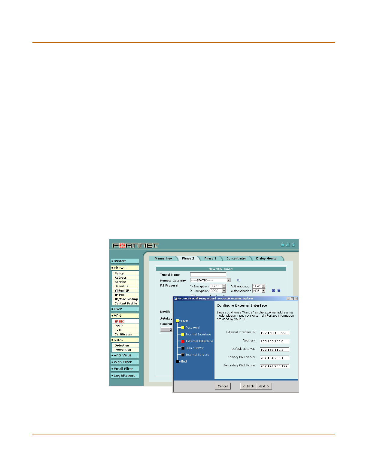
Figure 1: The FortiGate web-based manager and setup wizard
20 Fortinet Inc.
Page 21

Introduction Secure installation, configuration, and management
Command line interface
You can access the FortiGate command line interface (CLI) by connecting a
management computer serial port to the FortiGate RS-232 serial Console connector.
You can also use Telnet or a secure SSH connection to connect to the CLI from any
network connected to the FortiGate, including the Internet.
The CLI supports the same configuration and monitoring functionality as the
web-based manager. In addition, you can use the CLI for advanced configuration
options not available from the web-based manager. This Installation and
Configuration Guide contains information about basic and advanced CLI commands.
You can find a more complete description of connecting to and using the FortiGate CLI
in the FortiGate CLI Reference Guide.
Logging and reporting
The FortiGate supports logging of various categories of traffic and of configuration
changes. You can configure logging to:
• report traffic that connects to the firewall,
• report network services used,
• report traffic permitted by firewall policies,
• report traffic that was denied by firewall policies,
• report events such as configuration changes and other management events, IPSec
tunnel negotiation, virus detection, attacks, and web page blocking,
• report attacks detected by the NIDS,
• send alert email to system administrators to report virus incidents, intrusions, and
firewall or VPN events or violations.
Logs can be sent to a remote syslog server or to a WebTrends NetIQ Security
Reporting Center and Firewall Suite server using the WebTrends enhanced log
format. Some models can also save logs to an optional internal hard drive. If a hard
drive is not installed, you can configure most FortiGates to log the most recent events
and attacks detected by the NIDS to shared system memory.
FortiGate-400 Installation and Configuration Guide 21
Page 22

What’s new in Version 2.50 Introduction
What’s new in Version 2.50
This section presents a brief summary of some of the new features in FortiOS v2.50:
System administration
• Improved graphical FortiGate system health monitoring that includes CPU and
memory usage, session number and network bandwidth usage, and the number of
viruses and intrusions detected. See “System status” on page 110.
• Revised antivirus and attack definition update functionality that connects to a new
version of the FortiResponse Distribution network. Updates can now be scheduled
hourly and the System > Update page displays more information about the current
update status. See “Updating antivirus and attack definitions” on page 115.
• Direct connection to the Fortinet tech support web page from the web-based
manager. You can register your FortiGate unit and get access to other technical
support resources. See “Registering FortiGate units” on page 125.
Network configuration
• Changes have been made to how zones are added and used. See “Configuring
zones” on page 133.
• Changes have been made to how VLANs are added and used. See “Configuring
VLANs” on page 139.
• New interface configuration options. See “Configuring interfaces” on page 135.
• Ping server and dead gateway detection for all interfaces.
• HTTP and Telnet administrative access to any interface.
• Secondary IP addresses for all FortiGate interfaces.
Routing
• Simplified direction-based routing configuration.
• Advanced policy routing (CLI only).
DHCP server
• DHCP server for the internal network (CLI only).
• Reserve IP/MAC pair combinations for DHCP servers (CLI only).
Routing Information Protocol (RIP)
• New RIP v1 and v2 functionality. See “RIP configuration” on page 149.
SNMP
• SNMP v1 and v2 support.
• Support for RFC 1213 and RFC 2665
• Monitoring of all FortiGate configuration and functionality
•See “Configuring SNMP” on page 162
22 Fortinet Inc.
Page 23

Introduction What’s new in Version 2.50
HA
• Active-active HA using switches and with the ability to select the schedule
• Transparent mode HA
• A/V update for HA clusters
• Configuration synchronizing for HA
See “High availability” on page 75.
Replacement messages
You can customize messages sent by the FortiGate unit:
• When a virus is detected,
• When a file is blocked,
• When a fragmented email is blocked
• When an alert email is sent
See “Customizing replacement messages” on page 164.
Firewall
• The firewall default configuration has changed. See “Default firewall configuration”
on page 170.
• Add virtual IPs to all interfaces. See “Virtual IPs” on page 188.
• Add content profiles to firewall policies to configure blocking, scanning, quarantine,
web content blocking, and email filtering. See “Content profiles” on page 197.
Users and authentication
• LDAP authentication. See “Configuring LDAP support” on page 205.
VPN
See the FortiGate VPN Guide for a complete description of FortiGate VPN
functionality. New features include:
•Phase 1
• AES encryption
• Certificates
• Advanced options including Dialup Group, Peer, XAUTH, NAT Traversal, DPD
•Phase 2
• AES encryption
• Encryption policies select service
• Generate and import local certificates
• Import CA certificates
FortiGate-400 Installation and Configuration Guide 23
Page 24

What’s new in Version 2.50 Introduction
NIDS
See the FortiGate NIDS Guide for a complete description of FortiGate NIDS
functionality. New features include:
• Attack detection signature groups
• User-configuration attack prevention
• Monitor multiple interfaces for attacks
• Monitor VLAN subinterfaces for attacks
• User-defined attack detection signatures
Antivirus
See the FortiGate Content Protection Guide for a complete description of FortiGate
antivirus functionality. New features include:
• Content profiles
• Quarantine for files containing viruses or files that are blocked
• Blocking oversized files
Web Filter
See the FortiGate Content Protection Guide for a complete description of FortiGate
web filtering functionality. New features include:
• Cerberian URL Filtering
Email filter
See the FortiGate Content Protection Guide for a complete description of FortiGate
email filtering functionality.
Logging and Reporting
See the FortiGate Logging and Message Reference Guide for a complete description
of FortiGate logging.
• Log to remote host CSV format
• Log message levels: Emergency, Alert, critical, error, Warning, notification,
information
• Log level policies
• Traffic log filter
• New antivirus, web filter, and email filter logs
• Alert email supports authentication
• Suppress email flooding
• Extended WebTrends support for graphing activity
24 Fortinet Inc.
Page 25

Introduction About this document
About this document
This installation and configuration guide describes how to install and configure the
FortiGate-400. This document contains the following information:
• Getting started describes unpacking, mounting, and powering on the FortiGate.
• NAT/Route mode installation describes how to install the FortiGate if you are
planning on running it in NAT/Route mode.
• Transparent mode installation describes how to install the FortiGate if you are
planning on running it in Transparent mode.
• High availability describes how to install and configure the FortiGate in a high
availability configuration.
• System status describes how to view the current status of your FortiGate unit and
related status procedures including installing updated FortiGate firmware, backing
up and restoring system settings, and switching between Transparent and
NAT/Route mode.
• Virus and attack definitions updates and registration describes configuring
automatic virus and attack definition updates. This chapter also contains
procedures for connecting to the FortiGate tech support webs site and for
registering your FortiGate unit.
• Network configuration describes configuring interfaces, zones, and VLANs and
configuring routing.
• RIP configuration describes the FortiGate RIP2 implementation and how to
configure RIP settings.
• System configuration describes system administration tasks available from the
System > Config web-based manager pages. This chapter describes setting
system time, adding and changed administrative users, configuring SNMP, and
editing replacement messages.
• Firewall configuration describes how to configure firewall policies to control traffic
through the FortiGate unit and apply content protection profiles to content traffic.
• Users and authentication describes how to add user names to the FortiGate user
database and how to configure the FortiGate to connect to a RADIUS server to
authenticate users.
• IPSec VPN describes how to configure FortiGate IPSec VPN.
• PPTP and L2TP VPN describes how to configure PPTP and L2TP VPNs between
the FortiGate and a windows client.
• Network Intrusion Detection System (NIDS) describes how to configure the
FortiGate NIDS to detect and prevent network attacks.
• Antivirus protection describes how use the FortiGate to protect your network from
viruses and worms.
• Web filtering describes how to configure web content filtering to prevent unwanted
Web content from passing through the FortiGate.
• Email filter describes how to configure email filtering to screen unwanted email
content.
• Logging and reporting describes how to configure logging and alert email to track
activity through the FortiGate.
•The Glossary defines many of the terms used in this document.
FortiGate-400 Installation and Configuration Guide 25
Page 26

Document conventions Introduction
Document conventions
This guide uses the following conventions to describe CLI command syntax.
• angle brackets < > to indicate variable keywords
For example:
execute restore config <filename_str>
You enter restore config myfile.bak
<xxx_str> indicates an ASCII string variable keyword.
<xxx_integer> indicates an integer variable keyword.
<xxx_ip> indicates an IP address variable keyword.
• vertical bar and curly brackets {|} to separate alternative, mutually exclusive
required keywords
For example:
set system opmode {nat | transparent}
You can enter set system opmode nat or set system opmode
transparent
• square brackets [ ] to indicate that a keyword is optional
For example:
get firewall ipmacbinding [dhcpipmac]
You can enter get firewall ipmacbinding or
get firewall ipmacbinding dhcpipmac
26 Fortinet Inc.
Page 27

Introduction Fortinet documentation
Fortinet documentation
Information about FortiGate products is available from the following FortiGate User
Manual volumes:
• Volume 1: FortiGate Installation and Configuration Guide
Describes installation and basic configuration for the FortiGate unit. Also describes
how to use FortiGate firewall policies to control traffic flow through the FortiGate
unit and how to use firewall policies to apply antivirus protection, web content
filtering, and email filtering to HTTP, FTP and email content passing through the
FortiGate unit.
• Volume 2: FortiGate VPN Guide
Contains in-depth information about FortiGate IPSec VPN using certificates, preshared keys and manual keys for encryption. Also contains basic configuration
information for the Fortinet Remote VPN Client, detailed configuration information
for FortiGate PPTP and L2TP VPN, and VPN configuration examples.
• Volume 3: FortiGate Content Protection Guide
Describes how to configure antivirus protection, web content filtering, and email
filtering to protect content as it passes through the FortiGate unit.
• Volume 4: FortiGate NIDS Guide
Describes how to configure the FortiGate NIDS to detect and protect the FortiGate
unit from network-based attacks.
• Volume 5: FortiGate Logging and Message Reference Guide
Describes how to configure FortiGate logging and alert email. Also contains the
FortiGate log message reference.
• Volume 6: FortiGate CLI Reference Guide
Describes the FortiGate CLI and contains a reference to all FortiGate CLI
commands.
The FortiGate online help also contains procedures for using the FortiGate web-based
manager to configure and manage your FortiGate unit.
Comments on Fortinet technical documentation
You can send information about errors or omissions in this document or any Fortinet
technical documentation to techdoc@fortinet.com.
FortiGate-400 Installation and Configuration Guide 27
Page 28

Customer service and technical support Introduction
Customer service and technical support
For antivirus and attack definition updates, firmware updates, updated product
documentation, technical support information, and other resources, please visit the
Fortinet technical support web site at http://support.fortinet.com.
You can also register FortiGate Antivirus Firewalls from http://support.fortinet.com and
modify your registration information at any time.
Fortinet email support is available from the following addresses:
amer_support@fortinet.com For customers in the United States, Canada, Mexico, Latin
apac_support@fortinet.com For customers in Japan, Korea, China, Hong Kong, Singapore,
eu_support@fortinet.com For customers in the United Kingdom, Scandinavia, Mainland
For information on Fortinet telephone support, see http://support.fortinet.com.
When requesting technical support, please provide the following information:
• Your name
• Company name
•Location
• Email address
• Telephone number
• FortiGate unit serial number
• FortiGate model
• FortiGate FortiOS firmware version
• Detailed description of the problem
America and South America.
Malaysia, all other Asian countries, and Australia.
Europe, Africa, and the Middle East.
28 Fortinet Inc.
Page 29

FortiGate-400 Installation and Configuration Guide Version 2.50 MR2
Getting started
This chapter describes unpacking, setting up, and powering on your FortiGate
Antivirus Firewall. When you have completed the procedures in this chapter, you can
proceed to one of the following:
• If you are going to operate the FortiGate unit in NAT/Route mode, go to
“NAT/Route mode installation” on page 45.
• If you are going to operate the FortiGate unit in Transparent mode, go to
“Transparent mode installation” on page 61.
• If you are going to operate two or more FortiGate units in HA mode, go to “High
availability” on page 75.
This chapter describes:
• Package contents
• Mounting
• Powering on
• Connecting to the web-based manager
• Connecting to the command line interface (CLI)
• Factory default FortiGate configuration settings
• Planning your FortiGate configuration
• FortiGate model maximum values matrix
• Next steps
FortiGate-400 Installation and Configuration Guide 29
Page 30
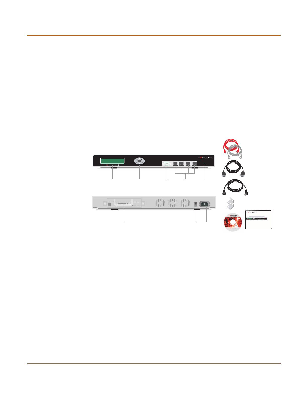
Package contents Getting started
Package contents
The FortiGate-400 package contains the following items:
• FortiGate-400 Antivirus Firewall
• one orange crossover ethernet cable
• one gray regular ethernet cable
• one null modem cable
• FortiGate-400 QuickStart Guide
• one power cable
• CD containing the FortiGate user documentation
• two 19-inch rack mount brackets
Figure 2: FortiGate-400 package contents
Ethernet Cables:
Orange - Crossover
Grey - Straight-through
Null-Modem Cable
(RS-232)
Esc Enter
Front
1
CONSOLE
4 / HA3
2
Mounting
LCD Control
Buttons
RS-232 Serial
Connection
Interface
1, 2, 3, 4/HA
Power
Light
Power Cable
Back
Rack-Mount Brackets
FortiGate-400
4 / HA3
1
CONSOLE
2
Esc Enter
QuickStart Guide
Copyright 2003 Fortinet Incorporated. All rights reserved.
Trademarks
Products mentioned in this document are trademarks.
Documentation
Removable
Hard Drive
Power
Switch
Power
Connection
USER MANUAL
The FortiGate-400 unit can be mounted in a standard 19-inch rack. It requires 1 U of
vertical space in the rack.
The FortiGate-400 unit can also be installed as a free-standing appliance on any
stable surface. For free-standing installation, make sure that the appliance has at least
1.5 in. (3.75 cm) of clearance on each side to allow for adequate air flow and cooling.
Dimensions
• 16.75 x 12 x 1.75 in. 42.7 x 30.5 x 4.5 cm
Weight
• 11 lb. (5 kg)
30 Fortinet Inc.
Page 31

Getting started Powering on
Power requirements
• Power dissipation: 180 W (max)
• AC input voltage: 100 to 240 VAC
• AC input current: 4 A
• Frequency: 47 to 63 Hz
Environmental specifications
• Operating temperature: 32 to 104°F (0 to 40°C)
• Storage temperature: -13 to 158°F (-25 to 70°C)
• Humidity: 5 to 95% non-condensing
Powering on
To power on the FortiGate-400 unit:
1 Make sure that the power switch on the back is turned off.
2 Connect the power cable to the power connection on the back of the FortiGate unit.
3 Connect the power cable to a power outlet.
4 Turn on the power switch.
After a few seconds, SYSTEM STARTING appears
on the LCD.
MAIN MENU appears on the LCD when the system
is up and running.
Table 1: FortiGate-400 LED indicators
LED State Description
Power Green The FortiGate unit is powered on.
Off The FortiGate unit is powered off.
1
2
3
4/HA
Amber The correct cable is in use, and the connected equipment has
Flashing
amber
Green The interface is connected at 100 Mbps.
Off No link established.
power.
Network activity at this interface.
FortiGate-400 Installation and Configuration Guide 31
Page 32
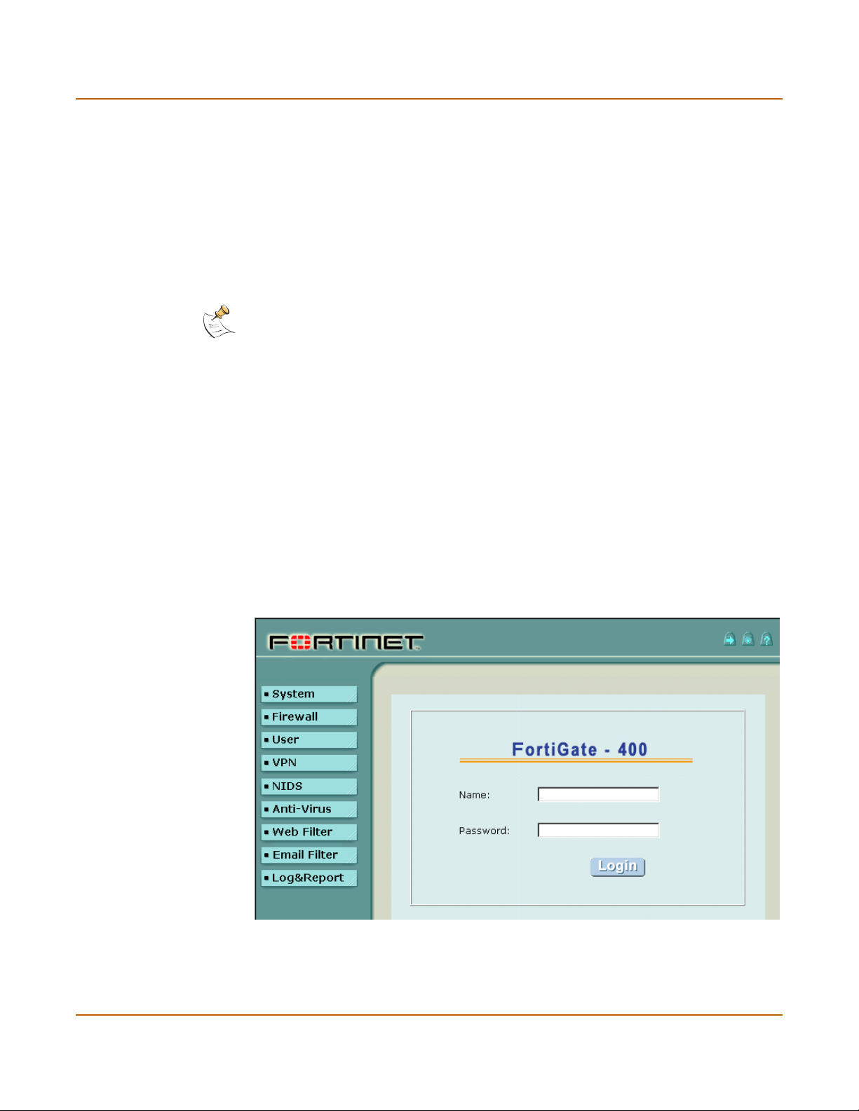
Connecting to the web-based manager Getting started
Connecting to the web-based manager
Use the following procedure to connect to the web-based manager for the first time.
Configuration changes made with the web-based manager are effective immediately
without the need to reset the firewall or interrupt service.
To connect to the web-based manager, you need:
• a computer with an ethernet connection,
• Internet Explorer version 4.0 or higher,
• a crossover cable or an ethernet hub and two ethernet cables.
Note: You can use the web-based manager with recent versions of most popular web browsers.
The web-based manager is fully supported for Internet Explorer version 4.0 or higher.
Connecting to the web-based manager
1 Set the IP address of the computer with an ethernet connection to the static IP
address 192.168.1.2 and a netmask of 255.255.255.0.
2 Using the crossover cable or the ethernet hub and cables, connect interface 1 of the
FortiGate unit to the computer ethernet connection.
3 Start Internet Explorer and browse to the address https://192.168.1.99 (remember to
include the “s” in https://).
The FortiGate login is displayed.
4 Type admin in the Name field and select Login.
The Register Now window is displayed. Use the information on this window to register
your FortiGate unit so that Fortinet can contact you for firmware updates. You must
also register to receive updates to the FortiGate virus and attack definitions.
Figure 3: FortiGate login
32 Fortinet Inc.
Page 33

Getting started Connecting to the command line interface (CLI)
Connecting to the command line interface (CLI)
As an alternative to the web-based manager, you can install and configure the
FortiGate unit using the CLI. Configuration changes made with the CLI are effective
immediately without the need to reset the firewall or interrupt service.
To connect to the FortiGate CLI, you need:
• a computer with an available communications port,
• the null modem cable included in your FortiGate package,
• terminal emulation software such as HyperTerminal for Windows.
Note: The following procedure describes how to connect to the CLI using Windows
HyperTerminal software. You can use any terminal emulation program.
To connect to the CLI:
1 Connect the null modem cable to the communications port of your computer and to
the FortiGate Console port.
2 Make sure that the FortiGate unit is powered on.
3 Start HyperTerminal, enter a name for the connection, and select OK.
4 Configure HyperTerminal to connect directly to the communications port on the
computer to which you have connected the null modem cable and select OK.
5 Select the following port settings and select OK.
Bits per second 9600
Data bits 8
Parity None
Stop bits 1
Flow control None
6 Press Enter to connect to the FortiGate CLI.
The following prompt appears:
FortiGate-400 login:
7 Type admin and press Enter twice.
The following prompt appears:
Type ? for a list of commands.
For information on how to use the CLI, see the FortiGate CLI Reference Guide.
Factory default FortiGate configuration settings
The FortiGate unit is shipped with a factory default configuration. This default
configuration allows you to connect to and use the FortiGate web-based manager to
configure the FortiGate unit onto your network. To configure the FortiGate unit onto
your network you add an administrator password, change network interface IP
addresses, add DNS server IP addresses, and configuring routing if required.
FortiGate-400 Installation and Configuration Guide 33
Page 34

Factory default FortiGate configuration settings Getting started
If you are planning on operating the FortiGate unit in Transparent mode, you can
switch to transparent mode from the factory default configuration and then configure
the FortiGate unit onto your network in Transparent mode.
Once the network configuration is complete, you can perform additional configuration
tasks such as setting system time, configuring virus and attack definition updates, and
registering the FortiGate unit.
The factory default firewall configuration includes a single network address translation
(NAT) policy that allows users on your internal network to connect to the external
network, and stops users on the external network from connecting to the internal
network. You can add more policies to provide more control of the network traffic
passing through the FortiGate unit.
The factory default content profiles can be used to quickly apply different levels of
antivirus protection, web content filtering, and email filtering to the network traffic
controlled by firewall policies.
• Factory default NAT/Route mode network configuration
• Factory default Transparent mode network configuration
• Factory default firewall configuration
• Factory default content profiles
Factory default NAT/Route mode network configuration
When the FortiGate unit is first powered on, it is running in NAT/Route mode and has
the basic network configuration listed in Ta bl e 2. This configuration allows you to
connect to the FortiGate unit web-based manager and establish the configuration
required to connect the FortiGate unit to your network. In Table 2 HTTPS
management access means you can connect to the web-based manager using this
interface. Ping management access means this interface responds to ping requests.
Table 2: Factory default NAT/Route mode network configuration
Administrator
account
Interface 1
Interface 2
Interface 3
IP: 192.168.1.99
Netmask: 255.255.255.0
Management Access: HTTPS, Ping
IP: 192.168.100.99
Netmask: 255.255.255.0
Default Gateway: 192.168.100.1
Primary DNS Server: 207.194.200.1
Secondary DNS Server: 207.194.200.129
Management Access: Ping
IP: 0.0.0.0
Netmask: 0.0.0.0
Management Access: HTTPS, Ping
User name: admin
Password: (none)
34 Fortinet Inc.
Page 35

Getting started Factory default FortiGate configuration settings
Table 2: Factory default NAT/Route mode network configuration (Continued)
IP: 0.0.0.0
Interface 4/HA
Netmask: 0.0.0.0
Management Access: Ping
Factory default Transparent mode network configuration
If you switch the FortiGate unit to Transparent mode, it has the default network
configuration listed in Ta bl e 3 .
Table 3: Factory default Transparent mode network configuration
Administrator
account
Management IP
DNS
Management access
User name: admin
Password: (none)
IP: 10.10.10.1
Netmask: 255.255.255.0
Primary DNS Server: 207.194.200.1
Secondary DNS Server: 207.194.200.129
Interface 1 HTTPS, Ping
Interface 2 Ping
Interface 3 Ping
Interface 4/HA Ping
Factory default firewall configuration
The factory default firewall configuration is the same in NAT/Route and Transparent
mode.
Table 4: Factory default firewall configuration
Port 1
Address
Port 2
Address
Recurring
Schedule
Firewall
Policy
Port1_All
Port2_All
Always The schedule is valid at all times. This means that
Port1->Port2 Firewall policy for connections from the internal
Source Port1_All The policy source address. Internal_All means that
Destination Port2_All The policy destination address. External_All means
Schedule Always The policy schedule. Always means that the policy
Service ANY The policy service. ANY means that this policy
IP: 0.0.0.0 Represents all of the IP addresses on the network
Mask: 0.0.0.0
IP: 0.0.0.0 Represents all of the IP addresses on the network
Mask: 0.0.0.0
connected to port 1.
connected to port 2.
the firewall policy is valid at all times.
network to the external network.
the policy accepts connections from any internal IP
address.
that the policy accepts connections with a
destination address to any IP address on the
external network.
is valid at any time.
processes connections for all services.
FortiGate-400 Installation and Configuration Guide 35
Page 36

Factory default FortiGate configuration settings Getting started
Table 4: Factory default firewall configuration (Continued)
Action ACCEPT The policy action. ACCEPT means that the policy
; NAT NAT is selected for the NAT/Route mode default
Traffic Shaping Traffic shaping is not selected. The policy does not
Authentication Authentication is not selected. Users do not have to
Antivirus & Web Filter Antivirus & Web Filter is not selected. This policy
Log Traffic Log Traffic is not selected. This policy does not
allows connections.
policy so that the policy applies network address
translation to the traffic processed by the policy.
NAT is not available for Transparent mode policies.
apply traffic shaping to the traffic controlled by the
policy. You can select this option to control the
maximum or minimum amount of bandwidth
available to traffic processed by the policy.
authenticate with the firewall before connecting to
their destination address. You can configure user
groups and select this option to require users to
authenticate with the firewall before they can
connect through the firewall.
does not include a content profile that applies
antivirus protection, web content filtering, or email
filtering to content traffic processed by this policy.
You can select this option and select a content
profile to apply different levels of content protection
to traffic processed by this policy.
record messages to the traffic log for the traffic
processed by this policy. You can configure
FortiGate logging and select Log Traffic to record all
connections through the firewall that are accepted
by this policy.
Factory default content profiles
You can use content profiles to apply different protection settings for content traffic
controlled by firewall policies. You can use content profiles for:
• Antivirus protection of HTTP, FTP, IMAP, POP3, and SMTP network traffic
• Web content filtering for HTTP network traffic
• Email filtering for IMAP and POP3 network traffic
• Oversized file and email blocking for HTTP, FTP, POP3, SMTP, and IMAP network
traffic
• Passing fragmented emails in IMAP, POP3, and SMTP email traffic
Using content profiles you can build up protection configurations that can be easily
applied to different types of Firewall policies. This allows you to customize different
types and different levels of protection for different firewall policies.
For example, while traffic between internal and external addresses might need strict
protection, traffic between trusted internal addresses might need moderate protection.
You can configure policies for different traffic services to use the same or different
content profiles.
Content profiles can be added to NAT/Route mode and Transparent mode policies.
36 Fortinet Inc.
Page 37

Getting started Factory default FortiGate configuration settings
Strict content profile
Use the strict content profile to apply maximum content protection to HTTP, FTP,
IMAP, POP3, and SMTP content traffic. You would not use the strict content profile
under normal circumstances, but it is available if you are having extreme problems
with viruses and require maximum content screening protection.
Table 5: Strict content profile
Options HTTP FTP IMAP POP3 SMTP
Antivirus Scan ;;;;;
File Block ;;;;;
Quarantine ;;;;;
Web URL Block ;
Web Content Block ;
Web Script Filter ;
Web Exempt List ;
Email Block List ;;
Email Exempt List ;;
Email Content Block ;;
Oversized File/Email Block block block block block block
Pass Fragmented Emails
Scan content profile
Use the scan content profile to apply antivirus scanning to HTTP, FTP, IMAP, POP3,
and SMTP content traffic. Quarantine is also selected for all content services. On
FortiGate models with a hard drive, if antivirus scanning finds a virus in a file, the file is
quarantined on the FortiGate hard disk. If required, system administrators can recover
quarantined files.
Table 6: Scan content profile
Options HTTP FTP IMAP POP3 SMTP
Antivirus Scan ;;;;;
File Block
Quarantine ;;;;;
Web URL Block
Web Content Block
Web Script Filter
Web Exempt List
Email Block List
Email Exempt List
Email Content Block
Oversized File/Email Block pass pass pass pass pass
Pass Fragmented Emails
FortiGate-400 Installation and Configuration Guide 37
Page 38

Factory default FortiGate configuration settings Getting started
Web content profile
Use the web content profile to apply antivirus scanning and Web content blocking to
HTTP content traffic. You can add this content profile to firewall policies that control
HTTP traffic.
Table 7: Web content profile
Options HTTP FTP IMAP POP3 SMTP
Antivirus Scan ;
File Block
Quarantine ;
Web URL Block ;
Web Content Block ;
Web Script Filter
Web Exempt List
Email Block List
Email Exempt List
Email Content Block
Oversized File/Email Block pass pass pass pass pass
Pass Fragmented Emails
Unfiltered content profile
Use the unfiltered content profile if you do not want to apply any content protection to
content traffic. You can add this content profile to firewall policies for connections
between highly trusted or highly secure networks where content does not need to be
protected.
Table 8: Unfiltered content profile
Options HTTP FTP IMAP POP3 SMTP
Antivirus Scan
File Block
Quarantine
Web URL Block
Web Content Block
Web Script Filter
Web Exempt List ;
Email Block List
Email Exempt List ;;
Email Content Block
Oversized File/Email Block pass pass pass pass pass
Pass Fragmented Emails ;;;
38 Fortinet Inc.
Page 39

Getting started Planning your FortiGate configuration
Planning your FortiGate configuration
Before beginning to configure the FortiGate unit, you need to plan how to integrate the
unit into your network. Among other things, you have to decide whether or not the unit
will be visible to the network, which firewall functions it will provide, and how it will
control the traffic flowing between its interfaces.
Your configuration plan is dependent upon the operating mode that you select. The
FortiGate unit can be configured in either of two modes: NAT/Route mode (the default)
or Transparent mode.
NAT/Route mode
In NAT/Route mode, the unit is visible to the network. Like a router, all of its interfaces
are on different subnets. The following interfaces are available in NAT/Route mode:
• Interfaces 1, 2, 3, and 4/HA can be connected to any networks. By default, the
FortiGate-400 interfaces have the following configuration
• Interface 1 is the default interface to the internal network (usually the Internet).
• Interface 2 is the default interface to the external network.
• Interface 3 can be connected to another network such as a DMZ network.
• Interface 4/HA can be connected to another network. Interface 4/HA can also
be connected to other FortiGate-400s if you are installing an HA cluster.
You can add security policies to control whether communications through the
FortiGate unit operate in NAT mode or in route mode. Security policies control the flow
of traffic based on each packet’s source address, destination address and service. In
NAT mode, the FortiGate performs network address translation before the packet is
sent to the destination network. In route mode, no translation takes place.
By default, the FortiGate unit has a NAT mode security policy that allows users on the
internal network to securely download content from the external network. No other
traffic is possible until you have configured more security policies.
You would typically use NAT/Route mode when the FortiGate unit is used as a
gateway between private and public networks. In this configuration, you would create
NAT mode policies to control traffic flowing between the internal, private network and
the external, public network (usually the Internet).
If you have multiple internal networks, such as a DMZ network in addition to the
internal, private network, you could create route mode policies for traffic flowing
between them.
FortiGate-400 Installation and Configuration Guide 39
Page 40
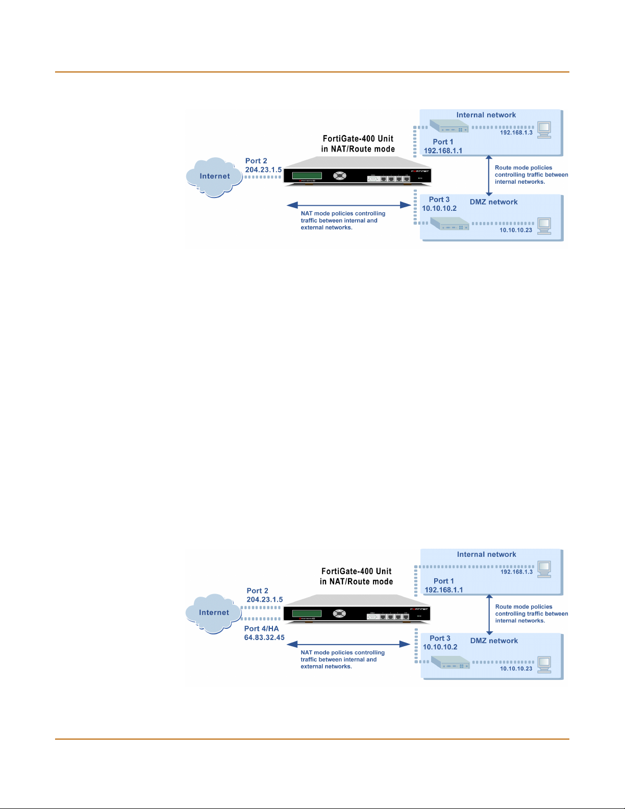
Planning your FortiGate configuration Getting started
Figure 4: Example NAT/Route mode network configuration
NAT/Route mode with multiple external network connections
In NAT/Route mode, you can configure the FortiGate unit with multiple redundant
connections to the external network (usually the Internet). For example, you could
create the following configuration:
• Interface 1 is the interface to the internal network.
• Interface 2 is the default interface to the external network (usually the Internet).
• Interface 3 is the interface to the DMZ network.
• Interface 4/HA is the redundant interface to the external network.
You must configure routing to support redundant internet connections. Routing can be
used to automatically re-direct connections from an interface if its connection to the
external network fails.
Otherwise, security policy configuration is similar to a NAT/Route mode configuration
with a single Internet connection. You would create NAT mode policies to control traffic
flowing between the internal, private network and the external, public network (usually
the Internet).
If you have multiple internal networks, such as a DMZ network in addition to the
internal, private network, you could create route mode policies for traffic flowing
between them.
Figure 5: Example NAT/Route multiple internet connection configuration
40 Fortinet Inc.
Page 41
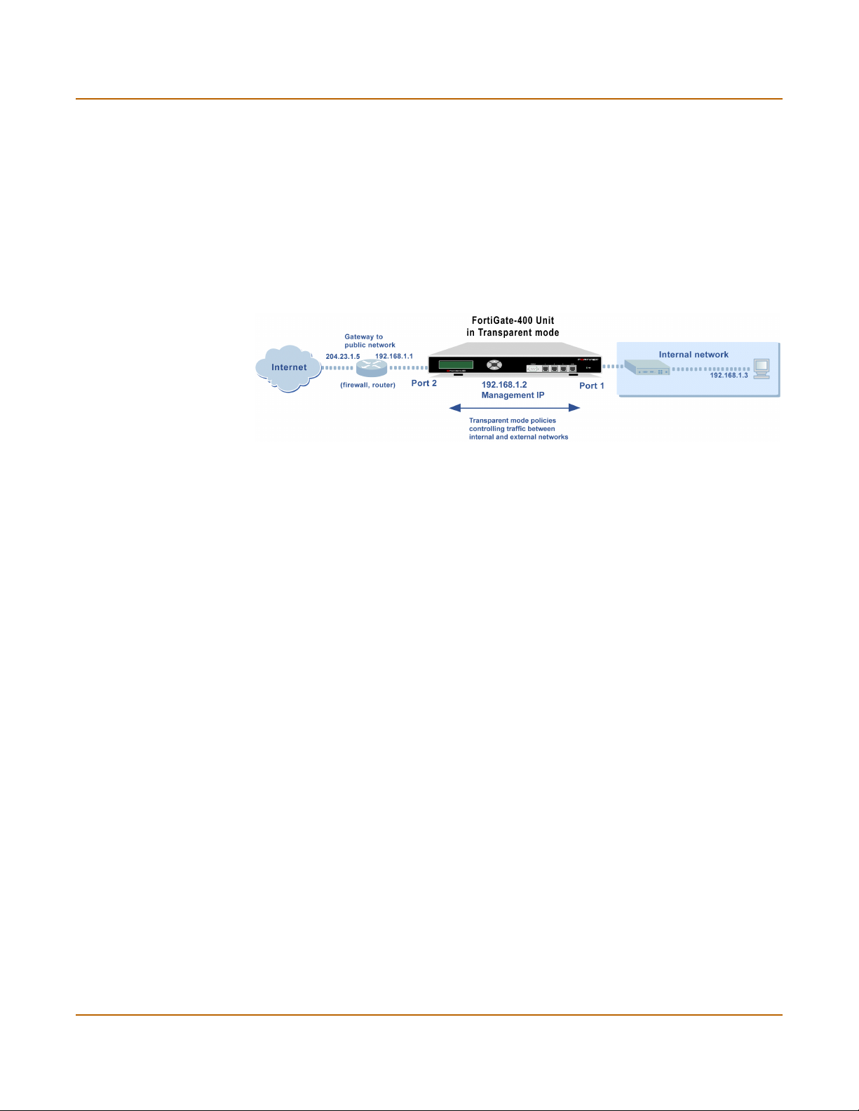
Getting started Planning your FortiGate configuration
Transparent mode
In Transparent mode, the FortiGate unit is invisible to the network. Similar to a
network bridge, all of FortiGate interfaces must be on the same subnet. You only have
to configure a management IP address so that you can make configuration changes.
The management IP address is also used for antivirus and attack definition updates.
You would typically use the FortiGate unit in Transparent mode on a private network
behind an existing firewall or behind a router. The FortiGate unit performs firewalling
as well as antivirus and content scanning but not VPN.
Figure 6: Example Transparent mode network configuration
You can connect up to four network segments to the FortiGate unit to control traffic
between these network segments.
• Interface 1 can connect to the internal firewall or router.
• Interface 2 can connect to the external network.
• Interface 3 can connect to another network.
• Interface 4/HA connect to another network. Interface 4/HA can also connect to
other FortiGate-400s if you are installing an HA cluster.
Configuration options
Once you have selected Transparent or NAT/Route mode operation, you can
complete your configuration plan, and begin configuring the FortiGate unit.
You can use the web-based manager setup wizard, the control buttons and LCD, or
the command line interface (CLI) for the basic configuration of the FortiGate unit.
Setup Wizard
If you are configuring the FortiGate unit to operate in NAT/Route mode (the default),
the Setup Wizard prompts you to add the administration password and the internal
and external interface addresses. Using the wizard, you can also add DNS server IP
addresses and a default route for the external interface.
In NAT/Route mode you can also configure the FortiGate to allow Internet access to
your internal Web, FTP, or email servers.
If you are configuring the FortiGate unit to operate in Transparent mode, you can
switch to Transparent mode from the web-based manager and then use the Setup
Wizard to add the administration password, the management IP address and
gateway, and the DNS server addresses.
FortiGate-400 Installation and Configuration Guide 41
Page 42

FortiGate model maximum values matrix Getting started
CLI
If you are configuring the FortiGate unit to operate in NAT/Route mode, you can add
the administration password and all interface addresses. Using the CLI, you can also
add DNS server IP addresses and a default route for the external interface.
If you are configuring the FortiGate unit to operate in Transparent mode, you can use
the CLI to switch to Transparent mode, Then you can add the administration
password, the management IP address and gateway, and the DNS server addresses.
Front keypad and LCD
If you are configuring the FortiGate unit to operate in NAT/Route mode, you can use
the control buttons and LCD to add the IP address of the FortiGate interfaces as well
as the external default gateway.
If you are configuring the FortiGate unit to operate in Transparent mode, you can use
the control buttons and LCD to switch to Transparent mode. Then you can add the
management IP address and default gateway.
FortiGate model maximum values matrix
Table 9: FortiGate maximum values matrix
FortiGate model
50 60 100 200 300 400 500 1000 2000 3000 3600
Policy 200 500 1000 2000 5000 5000 20000 50000 50000 50000 50000
Address 500 500 500 500 3000 3000 6000 10000 10000 10000 10000
Address group 500 500 500 500 500 500 500 500 500 500 500
Service 500 500 500 500 500 500 500 500 500 500 500
Service group 500 500 500 500 500 500 500 500 500 500 500
Recurring schedule 256 256 256 256 256 256 256 256 256 256 256
Onetime schedule 256 256 256 256 256 256 256 256 256 256 256
User 20 500 1000 1000 1000 1000 1000 1000 1000 1000 1000
User group 100 100 100 100 100 100 100 100 100 100 100
Group members 300 300 300 300 300 300 300 300 300 300 300
Virtual IPs 500 500 500 500 500 500 500 500 500 500 500
IP/MAC binding 50 100 1000 1000 2000 2000 2000 5000 5000 5000 5000
Route 500 500 500 500 500 500 500 500 500 500 500
Policy route gateway 500 500 500 500 500 500 500 500 500 500 500
Admin user 500 500 500 500 500 500 500 500 500 500 500
IPsec Phase 1 20 50 80 200 1500 1500 3000 5000 5000 5000 5000
VPN concentrator 500 500 500 500 500 500 500 500 500 500 500
VLAN subinterface N/A N/A N/A N/A N/A 1024* 1024* 2048* 2048* 8192* 8192*
Zone N/A N/A N/A N/A N/A 100 100 200 200 300 500
42 Fortinet Inc.
Page 43

Getting started Next steps
Table 9: FortiGate maximum values matrix
FortiGate model
50 60 100 200 300 400 500 1000 2000 3000 3600
IP pool 50 50 50 50 50 50 50 50 50 50 50
RADIUS server 66666666666
File pattern 56 56 56 56 56 56 56 56 56 56 56
PPTP user 500 500 500 500 500 500 500 500 500 500 500
L2TP user 500 500 500 500 500 500 500 500 500 500 500
URL block no limit no limit no limit no limit no limit no limit no limit no limit no limit no limit no limit
Content block no limit no limit no limit no limit no limit no limit no limit no limit no limit no limit no limit
Exempt URL no limit no limit no limit no limit no limit no limit no limit no limit no limit no limit no limit
Next steps
Now that your FortiGate unit is operating, you can proceed to configure it to connect to
networks:
• If you are going to operate the FortiGate unit in NAT/Route mode, go to
“NAT/Route mode installation” on page 45.
• If you are going to operate the FortiGate unit in Transparent mode, go to
“Transparent mode installation” on page 61.
• If you are going to operate two or more FortiGate units in HA mode, go to “High
availability” on page 75.
FortiGate-400 Installation and Configuration Guide 43
Page 44

Next steps Getting started
44 Fortinet Inc.
Page 45

FortiGate-400 Installation and Configuration Guide Version 2.50 MR2
NAT/Route mode installation
This chapter describes how to install your FortiGate unit in NAT/Route mode. To install
your FortiGate unit in Transparent mode, see “Transparent mode installation” on
page 61. To install two or more FortiGate units in HA mode, see “High availability” on
page 75.
This chapter describes:
• Preparing to configure NAT/Route mode
• Using the setup wizard
• Using the front control buttons and LCD
• Using the command line interface
• Completing the configuration
• Connecting the FortiGate unit to your networks
• Configuring your network
• Completing the configuration
• Configuration example: Multiple connections to the Internet
Preparing to configure NAT/Route mode
Use Tab le 10 to gather the information that you need to customize NAT/Route mode
settings.
Table 10: NAT/Route mode settings
Administrator Password:
Interface 1
Interface 2
Interface 3
(optionally connect
to a DMZ network)
FortiGate-400 Installation and Configuration Guide 45
IP: _____._____._____._____
Netmask: _____._____._____._____
IP: _____._____._____._____
Netmask: _____._____._____._____
Default Gateway: _____._____._____._____
Primary DNS Server: _____._____._____._____
Secondary DNS Server: _____._____._____._____
IP: _____._____._____._____
Netmask: _____._____._____._____
Page 46

Using the setup wizard NAT/Route mode installation
Table 10: NAT/Route mode settings (Continued)
Interface 4/HA
Internal servers
Using the setup wizard
From the web-based manager, you can use the setup wizard to create the initial
configuration of your FortiGate unit. To connect to the web-based manager, see
“Connecting to the web-based manager” on page 32.
Starting the setup wizard
To start the setup wizard:
IP: _____._____._____._____
Netmask: _____._____._____._____
Web Server: _____._____._____._____
SMTP Server: _____._____._____._____
POP3 Server: _____._____._____._____
IMAP Server: _____._____._____._____
FTP Server: _____._____._____._____
If you provide access from the Internet to a web server, mail server,
IMAP server, or FTP server installed on an internal network, add the IP
addresses of the servers here.
1 Select Easy Setup Wizard (the middle button in the upper-right corner of the
web-based manager).
2 Use the information that you gathered in Table 10 on page 45 to fill in the wizard fields.
Select the Next button to step through the wizard pages.
3 Confirm your configuration settings and then select Finish and Close.
Note: If you use the setup wizard to configure internal server settings, the FortiGate unit adds
port forwarding virtual IPs and firewall policies for each server. For each server located in your
Internal zone the FortiGate unit adds an External->Internal policy. For each server located in
your DMZ zone, the FortiGate unit adds an External->DMZ policy.
Reconnecting to the web-based manager
If you changed the IP address of interface 1 while you were using the setup wizard,
you must reconnect to the web-based manager using a new IP address. Browse to
https:// followed by the new IP address of interface 1. Otherwise, you can reconnect to
the web-based manager by browsing to https://192.168.1.99.
You have now completed the initial configuration of your FortiGate unit, and can
proceed to “Completing the configuration” on page 50.
46 Fortinet Inc.
Page 47

NAT/Route mode installation Using the front control buttons and LCD
Using the front control buttons and LCD
As an alternative to the setup wizard, use the information that you recorded in
Table 10 on page 45 to complete the following procedure. Starting with Main Menu
displayed on the LCD, use the front control buttons and LCD:
1 Press Enter three times to configure the PORT1 IP
address.
2 Set the PORT1 IP address.
Use the up and down arrow keys to increase or decrease the value of each IP address
digit. Press Enter to move to the next digit. Press Esc to move to the previous digit.
Note: When you enter an IP address, the LCD display always shows three digits for each part
of the address. For example, the IP address 192.168.100.1 appears on the LCD display as
192.168.100.001. The IP address 192.168.23.45 appears as 192.168.023.045.
3 When you have set the last digit of the IP address, press Enter.
4 Use the down arrow to highlight Netmask.
5 Press Enter and set the internal Netmask.
6 When you have set the last digit of the Netmask, press Enter.
7 Press Esc to return to the Main Menu.
8 Repeat these steps to configure PORT2, the PORT2 default gateway, PORT3, and
PORT4/HA if required.
You have now completed the basic configuration of your FortiGate unit, and you can
proceed to “Completing the configuration” on page 50.
Using the command line interface
As an alternative to using the setup wizard, you can configure the FortiGate unit using
the command line interface (CLI). To connect to the CLI, see “Connecting to the
command line interface (CLI)” on page 33.
Configuring the FortiGate unit to operate in NAT/Route mode
Use the information that you gathered in Table 10 on page 45 to complete the
following procedures.
Configuring NAT/Route mode IP addresses
1 Log into the CLI if you are not already logged in.
2 Set the IP address and netmask of interface 1 to the internal IP address and netmask
that you recorded in Table 10 on page 45. Enter:
set system interface port1 mode static ip <IP_address>
<netmask>
Example
set system interface port1 mode static ip 192.168.1.1
255.255.255.0
FortiGate-400 Installation and Configuration Guide 47
Page 48

Using the command line interface NAT/Route mode installation
3 Set the IP address and netmask of interface 2 to the external IP address and netmask
that you recorded in Table 10 on page 45.
set system interface port2 mode static ip <IP_address>
<netmask>
Example
set system interface port2 mode
255.255.255.0
4 Set the IP address and netmask of interface 3 or 4 to the IP addresses and netmasks
that you recorded in Table 10 on page 45.
set system interface <interface_name> mode static ip
<IP_address> <netmask>
Example
To set the IP address of interface 3 to 192.45.56.73 and netmask to 255.255.255.0,
enter
set system interface port3 mode
255.255.255.0
5 Confirm that the addresses are correct. Enter:
get system interface
The CLI lists the IP address, netmask and other settings for each of the FortiGate
interfaces.
6 Set the primary DNS server IP addresses. Enter
set system dns primary <IP address>
Example
set system dns primary 293.44.75.21
7 Optionally, set the secondary DNS server IP addresses. Enter
set system dns secondary <IP address>
Example
set system dns secondary 293.44.75.22
static
static
ip 204.23.1.5
ip 192.45.56.73
8 Set the default route to the Default Gateway IP address.
set system route number <route_no> dst 0.0.0.0 0.0.0.0 gw1
<gateway_ip>
Example
set system route number 0 dst 0.0.0.0 0.0.0.0 gw1 204.23.1.2
48 Fortinet Inc.
Page 49

NAT/Route mode installation Connecting the FortiGate unit to your networks
Connecting the FortiGate unit to your networks
When you have completed the initial configuration, you can connect the FortiGate unit
between your internal network and the Internet.
The FortiGate-400 has four 10/100Base-TX connectors that can be connected to up
to four different networks. You can connect them in any configuration. When you first
power on the FortiGate-400, the interfaces and zones are configured for the following
connections:
• interface 1 to connect to your internal network,
• interface 2 to connect to your public switch or router and the Internet,
• interface 3 to connect to a DMZ network,
• interface 4/HA to connect to another FortiGate-400 for high availability (see “High
availability” on page 75) or to connect to a fourth network.
Note: You can also create redundant connections to the internet by connecting two interfaces
to separate Internet connections. For example, you could connect interface 2 and 3 to different
Internet connections, each provided by a different service provider. See “Configuration
example: Multiple connections to the Internet” on page 52.
To connect the FortiGate unit running in NAT/Route mode:
1 Connect interface 1 to the hub or switch connected to your internal network.
2 Connect interface 2 to the public switch or router provided by your Internet Service
Provider.
3 Optionally connect interface 3 to your DMZ network.
You can use a DMZ network to provide access from the Internet to a web server or
other server without installing the servers on your internal network.
4 Optionally connect the 4/HA interface to a fourth network (not shown in Figure 7).
FortiGate-400 Installation and Configuration Guide 49
Page 50
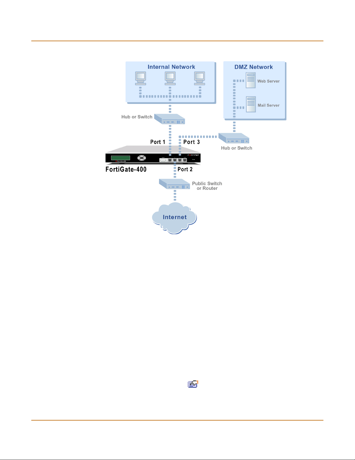
Configuring your network NAT/Route mode installation
Figure 7: FortiGate-400 NAT/Route mode connections
Configuring your network
If you are running the FortiGate unit in NAT/Route mode, your networks must be
configured to route all Internet traffic to the IP address of the FortiGate interface to
which they are connected.
Completing the configuration
Use the information in this section to complete the initial configuration of the FortiGate
unit.
Configuring interface 3
Use the following procedure to configure interface 3 to connect to a network:
1 Log into the web-based manager.
2 Go to System > Network > Interface.
3 Choose port3 and select Modify .
4 Change the IP address and Netmask as required.
5 Select Apply.
50 Fortinet Inc.
Page 51

NAT/Route mode installation Completing the configuration
Configuring interface 4/HA
Use the following procedure to configure interface 4/HA to connect to a network:
1 Log into the web-based manager.
2 Go to System > Network > Interface.
3 Choose port4/ha and select Modify .
4 Make sure that Work as HA is not selected.
5 Change the IP address and Netmask as required.
6 Select Apply.
Setting the date and time
For effective scheduling and logging, the FortiGate system date and time should be
accurate. You can either manually set the system date and time or you can configure
the FortiGate unit to automatically keep its time correct by synchronizing with a
Network Time Protocol (NTP) server.
To set the FortiGate system date and time, see “Setting system date and time” on
page 157.
Enabling antivirus protection
To enable antivirus protection to protect users on your internal network from
downloading a virus from the Internet:
1 Go to Firewall > Policy > port1->port2.
2 Select Edit to edit this policy.
3 Select Anti-Virus & Web filter to enable antivirus protection for this policy.
4 Select the Scan Content Profile.
5 Select OK to save your changes.
Registering your FortiGate unit
After purchasing and installing a new FortiGate unit, you can register the unit by going
to System > Update > Support, or using a web browser to connect to
http://support.fortinet.com and selecting Product Registration.
Registration consists of entering your contact information and the serial numbers of
the FortiGate units you or your organization have purchased. Registration is quick and
easy. You can register multiple FortiGate units in a single session without re-entering
your contact information. For more information about registration, see “Registering
FortiGate units” on page 125.
FortiGate-400 Installation and Configuration Guide 51
Page 52

Configuration example: Multiple connections to the Internet NAT/Route mode installation
Configuring virus and attack definition updates
You can go to System > Update to configure the FortiGate unit to automatically check
to see if new versions of the virus definitions and attack definitions are available. If it
finds new versions, the FortiGate unit automatically downloads and installs the
updated definitions.
The FortiGate unit uses HTTPS on port 8890 to check for updates. FortiGate interface
2 must have a path to the FortiResponse Distribution Network (FDN) using port 8890.
To configure automatic virus and attack updates, see “Updating antivirus and attack
definitions” on page 115.
Configuration example: Multiple connections to the Internet
This section describes some basic routing and firewall policy configuration examples
for a FortiGate unit with multiple connections to the Internet (see Figure 8). In this
topology, the organization operating the FortiGate unit uses two Internet service
providers to connect to the Internet. The FortiGate unit is connected to the Internet
using port 2 and port 3. Port 1 connects to gateway 1, operated by ISP1 and port 2
connects to gateway 2, operated by ISP2.
By adding ping servers to interfaces, and by configuring routing you can control how
traffic uses each Internet connection. With this routing configuration is place you can
proceed to create firewall policies to support multiple internet connections.
This section provides some examples of routing and firewall configurations to
configure the FortiGate unit for multiple internet connections. To use the information in
this section you should be familiar with FortiGate routing (see “Configuring routing” on
page 138) and FortiGate firewall configuration (see “Firewall configuration” on
page 169).
The examples below show how to configure destination-based routing and policy
routing to control different traffic patterns.
• Configuring Ping servers
• Destination based routing examples
• Policy routing examples
• Firewall policy example
52 Fortinet Inc.
Page 53

NAT/Route mode installation Configuration example: Multiple connections to the Internet
Figure 8: Example multiple Internet connection configuration
Configuring Ping servers
Use the following procedure to make Gateway 1 the ping server for port2 and
Gateway 2 the ping server for port3.
1 Go to System > Network > Interface.
2 For port2, select Modify .
• Ping Server: 1.1.1.1
• Select Enable Ping Server
•Select OK
3 For port3, select Modify .
• Ping Server: 2.2.2.1
• Select Enable Ping Server
•Select OK
FortiGate-400 Installation and Configuration Guide 53
Page 54

Configuration example: Multiple connections to the Internet NAT/Route mode installation
Using the CLI
1 Add a ping server to port2.
set system interface port2 config detectserver 1.1.1.1 gwdetect
enable
2 Add a ping server to port3.
set system interface port3 config detectserver 2.2.2.1 gwdetect
enable
Destination based routing examples
This section describes the following destination-based routing examples:
• Primary and backup links to the Internet
• Load sharing
• Load sharing and primary and secondary connections
Primary and backup links to the Internet
Use the following procedure to add a default destination-based route that directs all
outgoing traffic to Gateway 1. If Gateway 1 fails, all connections are re-directed to
Gateway 2. Gateway 1 is the primary link to the Internet and Gateway 2 is the backup
link.
1 Go to System > Network > Routing Table.
2 Select New.
• Destination IP: 0.0.0.0
• Mask: 0.0.0.0
• Gateway #1: 1.1.1.1
• Gateway #2: 2.2.2.1
• Device #1: port2
• Device #2: port3
•Select OK.
Using the CLI
1 Add the route to the routing table.
set system route number 0 dst 0.0.0.0 0.0.0.0 gw1 1.1.1.1
dev1 port2 gw2 2.2.2.1 dev2 dmz
Table 11: Route for primary and backup links
Destination IP Mask Gateway #1 Device #1 Gateway #2 Device #2
0.0.0.0 0.0.0.0 1.1.1.1 port2 2.2.2.1 port3
54 Fortinet Inc.
Page 55

NAT/Route mode installation Configuration example: Multiple connections to the Internet
Load sharing
You can also configure destination routing to direct traffic through both gateways at
the same time. If users on your internal network connect to the networks of ISP1 and
ISP2, you can add routes for each of these destinations. Each route can include a
backup destination to the network of the other ISP.
Table 12: Load sharing routes
Destination IP‘ Mask Gateway #1 Device #1 Gateway #2 Device #2
100.100.100.0 255.255.255.0 1.1.1.1 port2 2.2.2.1 port3
200.200.200.0 255.255.255.0 2.2.2.1 port3 1.1.1.1 port2
The first route directs all traffic destined for the 100.100.100.0 network out port2 to
gateway 1 with the IP address 1.1.1.1. If this router is down, traffic destined for the
100.100.100.0 network is re-directed out port3 to gateway 2 with the IP address
2.2.2.1.
Load sharing and primary and secondary connections
You can combine these routes into a more complete multiple internet connection
configuration. In the topology shown in Figure 8 on page 53, users on the internal
network would connect to the Internet to access web pages and other Internet
resources. However, they may also connect to services, such as email, provided by
their ISPs. You can combine the routes described in the previous examples to provide
users with a primary and backup connection to the Internet, while at the same time
routing traffic to each ISP network as required.
The routing described below allows a user on the internal network to connect to the
Internet through gateway 1 and ISP1. At the same time, this user can also connect
through to gateway 2 to access a mail server maintained by ISP2.
Adding the routes using the web-based manager
1 Go to System > Network > Routing Table.
2 Select New to add the default route for primary and backup links to the Internet.
• Destination IP: 0.0.0.0
• Mask: 0.0.0.0
• Gateway #1: 1.1.1.1
• Gateway #2: 2.2.2.1
• Device #1: port2
• Device #2: port3
•Select OK.
FortiGate-400 Installation and Configuration Guide 55
Page 56

Configuration example: Multiple connections to the Internet NAT/Route mode installation
3 Select New to add a route for connections to the network of ISP1.
• Destination IP: 100.100.100.0
• Mask: 255.255.255.0
• Gateway #1: 1.1.1.1
• Gateway #2: 2.2.2.1
• Device #1: port2
• Device #2: port3
4 Select New to add a route for connections to the network of ISP2.
• Destination IP: 200.200.200.0
• Mask: 255.255.255.0
• Gateway #1: 2.2.2.1
• Gateway #2: 1.1.1.1
• Device #1: port3
• Device #2: port2
•Select OK.
5 Change the order of the routes in the routing table to move the default route below the
other two routes.
• For the default route select Move to .
• Type a number in the Move to field to move this route to the bottom of the list.
If there are only 3 routes, type 3.
•Select OK.
Adding the routes using the CLI
1 Add the route for connections to the network of ISP2.
set system route number 1 dst 100.100.100.0 255.255.255.0 gw1
1.1.1.1 dev1 port2 gw2 2.2.2.1 dev2 port3
1 Add the route for connections to the network of ISP1.
set system route number 2 dst 200.200.200.0 255.255.255.0 gw1
2.2.2.1 dev1 port3 gw2 1.1.1.1 dev2 port2
2 Add the default route for primary and backup links to the Internet.
set system route number 3 dst 0.0.0.0 0.0.0.0 gw1 1.1.1.1
dev1 port2 gw2 2.2.2.1 dev2 port3
The routing table should have routes arranged as shown in Tab le 1 3.
Table 13: Example combined routing table
Destination IP‘ Mask Gateway #1 Device #1 Gateway #2 Device #2
100.100.100.0 255.255.255.0 1.1.1.1 port2 2.2.2.1 port3
200.200.200.0 255.255.255.0 2.2.2.1 port3 1.1.1.1 port2
0.0.0.0 0.0.0.0 1.1.1.1 port2 2.2.2.1 port3
56 Fortinet Inc.
Page 57

NAT/Route mode installation Configuration example: Multiple connections to the Internet
Policy routing examples
Policy routing can be added to increase the control you have over how packets are
routed. Policy routing works on top of destination-based routing. This means you
should configure destination-based routing first and then build policy routing on top to
increase the control provided by destination-based routing.
For example, if you have used destination-based routing to configure routing for dual
internet connections, you can use policy routing to apply more control to which traffic
is sent to which destination route. This section describes the following policy routing
examples, based on topology similar to that shown in Figure 8 on page 53.
Differences are noted in each example.
The policy routes described in these examples only work if you have already defined
destination routes similar to those described in the previous section.
• Routing traffic from internal subnets to different external networks
• Routing a service to an external network
For more information about policy routing, see “Policy routing” on page 146.
Routing traffic from internal subnets to different external networks
If the FortiGate provides internet access for multiple internal subnets, you can use
policy routing to control the route that traffic from each network takes to the Internet.
For example, if the internal network includes the subnets 192.168.10.0 and
192.168.20.0 you can enter the following policy routes:
1 Enter the following command to route traffic from the 192.168.10.0 subnet to the
100.100.100.0 external network:
set system route policy 1 src 192.168.10.0 255.255.255.0 dst
100.100.100.0 255.255.255.0 gw 1.1.1.1
2 Enter the following command to route traffic from the 192.168.20.0 subnet to the
200.200.200.0 external network:
set system route policy 2 src 192.168.20.0 255.255.255.0 dst
200.200.200.0 255.255.255.0 gw 2.2.2.1
Routing a service to an external network
You can use the following policy routes to direct all HTTP traffic (using port 80) to one
external network and all other traffic to the other external network.
1 Enter the following command to route all HTTP traffic using port 80 to the next hop
gateway with IP address 1.1.1.1.
set system route policy 1 src 0.0.0.0 0.0.0.0 dst 0.0.0.0
0.0.0.0 protocol 6 port 1 1000 gw 1.1.1.1
2 Enter the following command to route all other traffic to the next hop gateway with IP
address 2.2.2.1.
Set system route policy 2 src 0.0.0.0 0.0.0.0 dst 0.0.0.0
0.0.0.0 gw 2.2.2.1
FortiGate-400 Installation and Configuration Guide 57
Page 58

Configuration example: Multiple connections to the Internet NAT/Route mode installation
Firewall policy example
Firewall policies control how traffic flows through the FortiGate unit. Once routing for
multiple internet connections has been configured you must create firewall policies to
control which traffic is allowed through the FortiGate unit and the interfaces through
which this traffic can connect.
For traffic originating on the Internal network to be able to connect to the Internet
through both Internet connections, you must add redundant policies from the internal
interface to each interface that connects to the Internet. Once these policies have
been added, the routing configuration controls which internet connection is actually
used.
Adding a redundant default policy
Figure 8 on page 53 shows a FortiGate unit connected to the Internet using its port2
and port3 interfaces. The default policy allows all traffic from the port1 network to
connect to the Internet through the port2 interface. If you add a similar policy to the
port1 to port3 policy list, this policy will allow all traffic from the port1 network to
connect to the Internet through the port3 interface. With both of these policies added
to the firewall configuration, the routing configuration will determine which Internet
connection the traffic from the internal network actually uses. For more information
about the default policy, see “Default firewall configuration” on page 170.
To add a redundant default policy
1 Go to Firewall > Address > port3.
2 Add the following address to port3.
Address Name Port3_All
IP Address 0.0.0.0
Netmask 0.0.0.0
3 Go to Firewall > Policy > port1->port3.
4 Select New.
5 Configure the policy to match the default policy.
Source Port1_All
Destination Port3_All
Schedule Always
Service ANY
Action Accept
NAT Select NAT.
6 Select OK to save your changes.
58 Fortinet Inc.
Page 59

NAT/Route mode installation Configuration example: Multiple connections to the Internet
Adding more firewall policies
In most cases your firewall configuration includes more than just the default policy.
However, the basic premise of creating redundant policies applies even as the firewall
configuration becomes more complex. To configure the FortiGate unit to use multiple
Internet connections you must add duplicate policies for connections between the
internal network and both interfaces connected to the Internet. As well, as you add
redundant policies, you must arrange them in both policy lists in the same order.
Restricting access to a single Internet connection
In some cases you might want to limit some traffic to only being able to use one
Internet connection. For example, in the topology shown in Figure 8 on page 53 the
organization might want its mail server to only be able to connect to the SMTP mail
server of ISP1. To do this, you add a single port1->port2 firewall policy for SMTP
connections. Because redundant policies have not been added, SMTP traffic from the
Internet network is always connected to ISP1. If the connection to ISP1 fails the SMTP
connection is not available.
FortiGate-400 Installation and Configuration Guide 59
Page 60

Configuration example: Multiple connections to the Internet NAT/Route mode installation
60 Fortinet Inc.
Page 61

FortiGate-400 Installation and Configuration Guide Version 2.50 MR2
Transparent mode installation
This chapter describes how to install your FortiGate unit in Transparent mode. If you
want to install the FortiGate unit in NAT/Route mode, see “NAT/Route mode
installation” on page 45. If you want to install two or more FortiGate units in HA mode,
see “High availability” on page 75.
This chapter describes:
• Preparing to configure Transparent mode
• Using the setup wizard
• Using the front control buttons and LCD
• Using the command line interface
• Completing the configuration
• Connecting the FortiGate unit to your networks
• Transparent mode configuration examples
Preparing to configure Transparent mode
Use Ta bl e 1 4 to gather the information that you need to customize Transparent mode
settings.
Table 14: Transparent mode settings
Administrator Password:
IP: _____._____._____._____
Netmask: _____._____._____._____
Management IP
The management IP address and netmask must be valid for the network
from which you will manage the FortiGate unit. Add a default gateway if the
FortiGate unit must connect to a router to reach the management
computer.
DNS Settings
Default Gateway: _____._____._____._____
Primary DNS Server: _____._____._____._____
Secondary DNS Server: _____._____._____._____
FortiGate-400 Installation and Configuration Guide 61
Page 62

Using the setup wizard Transparent mode installation
Using the setup wizard
From the web-based manager, you can use the setup wizard to create the initial
configuration of your FortiGate unit. To connect to the web-based manager, see
“Connecting to the web-based manager” on page 32.
Changing to Transparent mode
The first time that you connect to the FortiGate unit, it is configured to run in
NAT/Route mode. To switch to Transparent mode using the web-based manager:
1 Go to System > Status.
2 Select Change to Transparent Mode.
3 Select Transparent in the Operation Mode list.
4 Select OK.
The FortiGate unit changes to Transparent mode.
To reconnect to the web-based manager, change the IP address of your management
computer to 10.10.10.2. Connect to interface 1, 2, or 3 and browse to https:// followed
by the Transparent mode management IP address. The default FortiGate Transparent
mode Management IP address is 10.10.10.1.
Starting the setup wizard
To start the setup wizard:
1 Select Easy Setup Wizard (the middle button in the upper-right corner of the
web-based manager).
2 Use the information that you gathered in Table 14 on page 61 to fill in the wizard fields.
Select the Next button to step through the wizard pages.
3 Confirm your configuration settings and then select Finish and Close.
Reconnecting to the web-based manager
If you changed the IP address of the management interface while you were using the
setup wizard, you must reconnect to the web-based manager using the new IP
address. Browse to https:// followed by the new IP address of the management
interface. Otherwise, you can reconnect to the web-based manager by browsing to
https://10.10.10.1. If you connect to the management interface through a router, make
sure that you have added a default gateway for that router to the management IP
default gateway field.
62 Fortinet Inc.
Page 63

Transparent mode installation Using the front control buttons and LCD
Using the front control buttons and LCD
This procedure describes how to use the control buttons and LCD to configure
Transparent mode IP addresses. Use the information that you recorded in Table 14 on
page 61 to complete this procedure. Starting with Main Menu displayed on the LCD,
use the front control buttons and LCD:
1 Press Enter three times to configure the
management interface IP address.
2 Set the manager interface IP address.
Use the up and down arrow keys to increase or decrease the value of each IP address
digit. Press Enter to move to the next digit. Press Esc to move to the previous digit.
Note: When you enter an IP address, the LCD display always shows three digits for each part
of the address. For example, the IP address 192.168.100.1 appears on the LCD display as
192.168.100.001. The IP address 192.168.23.45 appears as 192.168.023.045.
3 When you have set the last digit of the IP address, press Enter.
4 Use the down arrow to highlight Netmask.
5 Press Enter and set the management IP Netmask.
6 When you have set the last digit of the Netmask, press Enter.
7 Press Esc to return to the Main Menu.
8 Repeat these steps to configure the default gateway if required.
Using the command line interface
As an alternative to the setup wizard, you can configure the FortiGate unit using the
command line interface (CLI). To connect to the CLI, see “Connecting to the command
line interface (CLI)” on page 33. Use the information that you gathered in Table 14 on
page 61 to complete the following procedures.
Changing to Transparent mode
1 Log into the CLI if you are not already logged in.
2 Switch to Transparent mode. Enter:
set system opmode transparent
After a few seconds, the login prompt appears.
3 Type admin and press Enter.
The following prompt appears:
Type ? for a list of commands.
4 Confirm that the FortiGate unit has switched to Transparent mode. Enter:
get system status
The CLI displays the status of the FortiGate unit. The last line shows the current
operation mode.
Operation mode: Transparent
FortiGate-400 Installation and Configuration Guide 63
Page 64

Completing the configuration Transparent mode installation
Configuring the Transparent mode management IP address
1 Log into the CLI if you are not already logged in.
2 Set the management IP address and netmask to the IP address and netmask that you
recorded in Table 14 on page 61. Enter:
set system management ip <IP address> <netmask>
Example
set system management ip 10.10.10.2 255.255.255.0
3 Confirm that the address is correct. Enter:
get system management
The CLI lists the management IP address and netmask.
Configure the Transparent mode default gateway
1 Log into the CLI if you are not already logged in.
2 Set the default route to the default gateway that you recorded in Table 14 on page 61.
Enter:
set system route number <number> gw1 <IP address>
Example
set system route
You have now completed the initial configuration of the FortiGate unit.
number 0 gw1
204.23.1.2
Completing the configuration
Use the information in this section to complete the initial configuration of the FortiGate
unit.
Setting the date and time
For effective scheduling and logging, the FortiGate system date and time should be
accurate. You can either manually set the system date and time or you can configure
the FortiGate unit to automatically keep its time correct by synchronizing with a
Network Time Protocol (NTP) server.
To set the FortiGate system date and time, see “Setting system date and time” on
page 157.
Enabling antivirus protection
To enable antivirus protection to protect users on your internal network from
downloading a virus from the Internet:
1 Go to Firewall > Policy > port1->port2.
2 Select Edit to edit this policy.
3 Select Anti-Virus & Web filter to enable antivirus protection for this policy.
4 Select the Scan Content Profile.
5 Select OK to save your changes.
64 Fortinet Inc.
Page 65

Transparent mode installation Connecting the FortiGate unit to your networks
Registering your FortiGate
After purchasing and installing a new FortiGate unit, you can register the unit by going
to System > Update > Support, or using a web browser to connect to
http://support.fortinet.com and selecting Product Registration.
Registration consists of entering your contact information and the serial numbers of
the FortiGate units you or your organization have purchased. Registration is quick and
easy. You can register multiple FortiGate units in a single session without re-entering
your contact information.
For more information about registration, see “Registering FortiGate units” on
page 125.
Configuring virus and attack definition updates
You can go to System > Update to configure the FortiGate unit to automatically check
to see if new versions of the virus definitions and attack definitions are available. If it
finds new versions, the FortiGate unit automatically downloads and installs the
updated definitions.
The FortiGate unit uses HTTPS on port 8890 to check for updates. FortiGate interface
2 must have a path to the FortiResponse Distribution Network (FDN) using port 8890.
To configure automatic virus and attack updates, see “Updating antivirus and attack
definitions” on page 115.
Connecting the FortiGate unit to your networks
When you have completed the initial configuration, you can connect the FortiGate-400
unit to your networks.
The FortiGate-400 has four 10/100Base-TX connectors that can be connected to up
to four different networks. You can connect them in any configuration.
For example, you can connect the FortiGate-400 interfaces using the following steps:
1 Connect interface 1 to the hub or switch connected to your internal network.
2 Connect interface 2 to the public switch or router provided by your Internet Service
Provider.
3 Optionally connect interfaces 3 and 4/HA to hubs or switches connected to your other
networks (the example shows a connection to interface 3).
FortiGate-400 Installation and Configuration Guide 65
Page 66
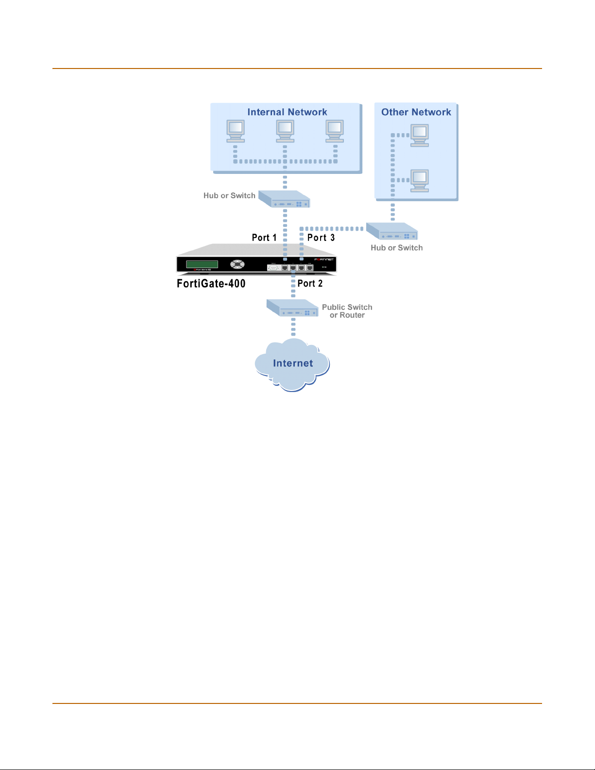
Transparent mode configuration examples Transparent mode installation
Figure 9: FortiGate-400 Transparent mode connections
Transparent mode configuration examples
A FortiGate unit operating in Transparent mode still requires a basic configuration to
operate as a node on the IP network. As a minimum, the FortiGate unit must be
configured with an IP address and subnet mask. These are used for management
access and to allow the unit to receive antivirus and definitions updates. Also, the unit
must have sufficient route information to reach:
• the management computer,
• The FortiResponse Distribution Network (FDN),
• a DNS server.
A route is required whenever the FortiGate unit connects to a router to reach a
destination. If all of the destinations are located on the external network, you may be
required to enter only a single default route. If, however, the network topology is more
complex, you may be required to enter one or more static routes in addition to the
default route.
66 Fortinet Inc.
Page 67

Transparent mode installation Transparent mode configuration examples
This section describes:
• Default routes and static routes
• Example default route to an external network
• Example static route to an external destination
• Example static route to an internal destination
Default routes and static routes
To create a route to a destination, you need to define an IP prefix which consists of an
IP network address and a corresponding netmask value. A default route matches any
prefix and forwards traffic to the next hop router (otherwise known as the default
gateway). A static route matches a more specific prefix and forwards traffic to the next
hop router.
Default route example:
IP Prefix 0.0.0.0 (IP address)
0.0.0.0 (Netmask)
Next Hop 192.168.1.2
Static Route example:
IP Prefix 172.100.100.0 (IP address)
255.255.255.0 (Netmask)
Next Hop 192.168.1.2
Note: When adding routes to the FortiGate unit, add the default route last so that it
appears on the bottom of the route list. This ensures that the unit will attempt to match
more specific routes before selecting the default route.
Example default route to an external network
Figure 10 shows a FortiGate unit where all destinations, including the management
computer, are located on the external network.To reach these destinations, the
FortiGate unit must connect to the “upstream” router leading to the external network.
To facilitate this connection, you must enter a single default route that points to the
upstream router as the next hop/default gateway.
FortiGate-400 Installation and Configuration Guide 67
Page 68
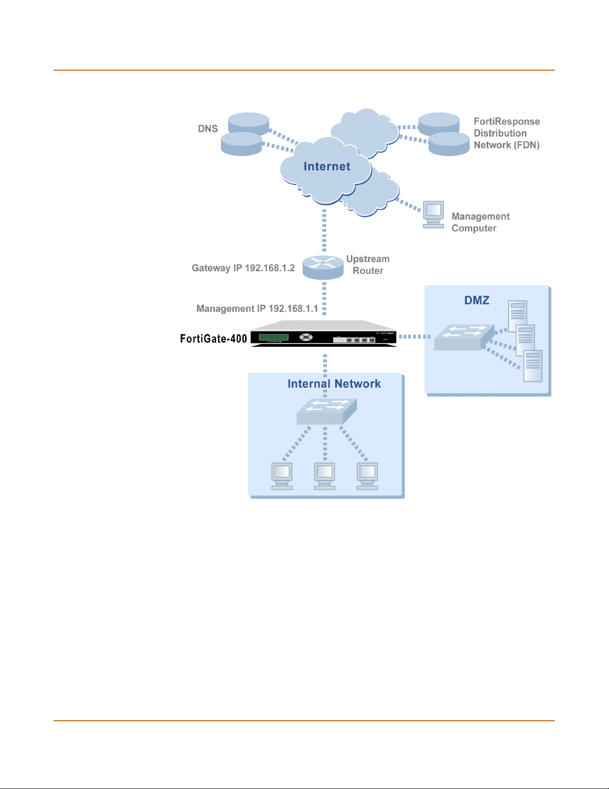
Transparent mode configuration examples Transparent mode installation
Figure 10: Default route to an external network
General configuration steps
1 Set the FortiGate unit to operate in Transparent mode.
2 Configure the Management IP address and Netmask of the FortiGate unit.
3 Configure the default route to the external network.
68 Fortinet Inc.
Page 69

Transparent mode installation Transparent mode configuration examples
Web-based manager example configuration steps
To configure basic Transparent mode settings and a default route using the
web-based manager:
1 Go to System > Status.
• Select Change to Transparent Mode.
• Select Transparent in the Operation Mode list.
•Select OK.
The FortiGate unit changes to Transparent mode.
2 Go to System > Network > Management.
• Change the Management IP and Netmask:
IP: 192.168.1.1
Mask: 255.255.255.0
• Select Apply.
3 Go to System > Network > Routing.
• Select New to add the default route to the external network.
Destination IP: 0.0.0.0
Mask: 0.0.0.0
Gateway: 192.168.1.2
•Select OK.
CLI configuration steps
To configure the Fortinet basic settings and a default route using the CLI:
1 Change the system to operate in Transparent Mode.
set system opmode transparent
2 Add the Management IP address and Netmask.
set system management ip 192.168.1.1 255.255.255.0
3 Add the default route to the external network.
set system route number 1 gw1 192.168.1.2
Example static route to an external destination
Figure 11 shows a FortiGate unit that requires routes to the FDN located on the
external network. The Fortigate unit does not require routes to the DNS servers or
management computer because they are located on the internal network.
To connect to the FDN, you would typically enter a single default route to the external
network. However, to provide an extra degree of security, you could enter static routes
to a specific FortiResponse server in addition to a default route to the external
network. If the static route becomes unavailable (perhaps because the IP address of
the FortiResponse server changes) the FortiGate unit will still be able to receive
antivirus and NIDS updates from the FDN using the default route.
FortiGate-400 Installation and Configuration Guide 69
Page 70
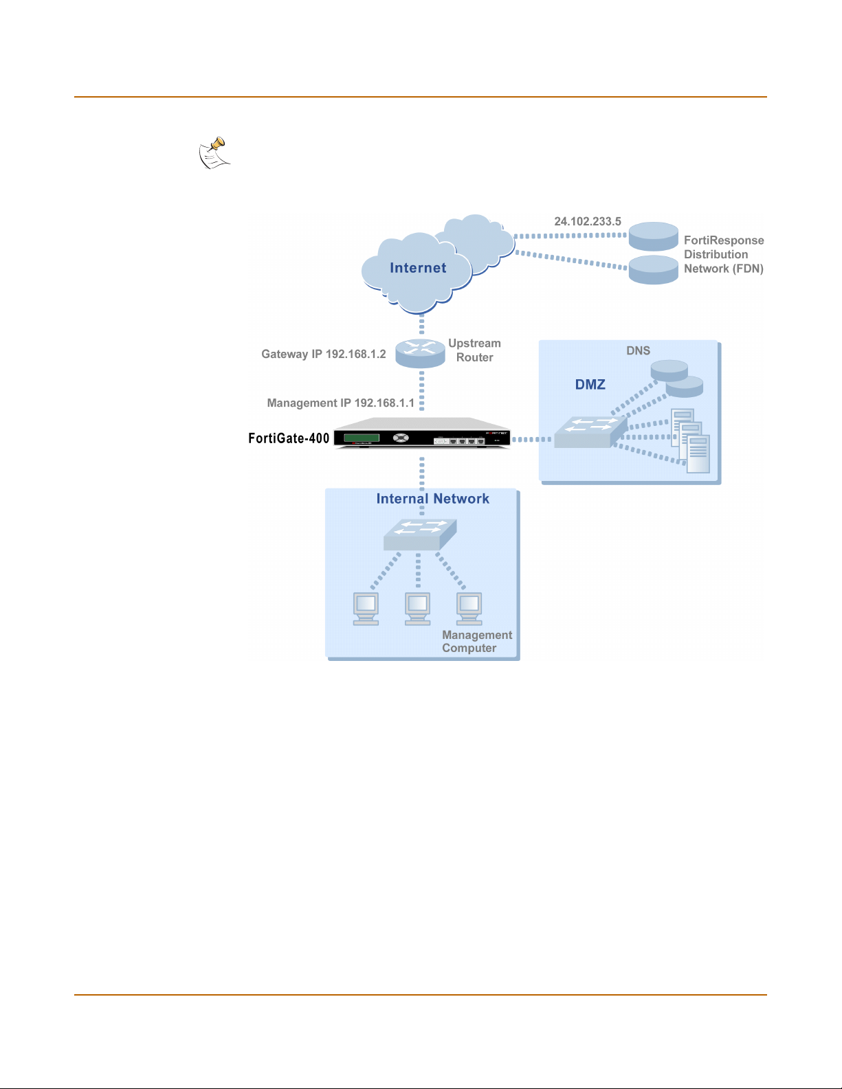
Transparent mode configuration examples Transparent mode installation
Note: This is an example configuration only. To configure a static route, you require a
destination IP address.
Figure 11: Static route to an external destination
General configuration steps
1 Set the FortiGate unit to operate in Transparent mode.
2 Configure the Management IP address and Netmask of the FortiGate unit.
3 Configure the static route to the FortiResponse server.
4 Configure the default route to the external network.
70 Fortinet Inc.
Page 71

Transparent mode installation Transparent mode configuration examples
Web-based manager example configuration steps
To configure the basic FortiGate settings and a static route using the web-based
manager:
1 Go to System > Status.
• Select Change to Transparent Mode.
• Select Transparent in the Operation Mode list.
•Select OK.
The FortiGate unit changes to Transparent mode.
2 Go to System > Network > Management.
• Change the Management IP and Netmask:
IP: 192.168.1.1
Mask: 255.255.255.0
• Select Apply.
3 Go to System > Network > Routing.
• Select New to add the static route to the FortiResponse server.
Destination IP: 24.102.233.5
Mask: 255.255.255.0
Gateway: 192.168.1.2
•Select OK.
• Select New to add the default route to the external network.
Destination IP: 0.0.0.0
Mask: 0.0.0.0
Gateway: 192.168.1.2
•Select OK.
CLI configuration steps
To configure the Fortinet basic settings and a static route using the CLI:
1 Set the system to operate in Transparent Mode.
set system opmode transparent
2 Add the Management IP address and Netmask.
set system management ip 192.168.1.1 255.255.255.0
3 Add the static route to the primary FortiResponse server.
set system route number 1 dst 24.102.233.5 255.255.255.0 gw1
192.168.1.2
4 Add the default route to the external network.
set system route number 2 gw1 192.168.1.2
FortiGate-400 Installation and Configuration Guide 71
Page 72
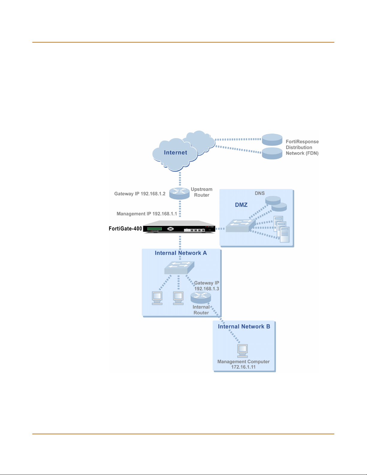
Transparent mode configuration examples Transparent mode installation
Example static route to an internal destination
Figure 12 shows a FortiGate unit where the FDN is located on an external subnet and
the management computer is located on a remote, internal subnet. To reach the FDN,
you need to enter a single default route that points to the upstream router as the next
hop/default gateway. To reach the management computer, you need to enter a single
static route that leads directly to it. This route will point to the internal router as the
next hop. (No route is required for the DNS servers because they are on the same
layer 3 subnet as the FortiGate unit.)
Figure 12: Static route to an internal destination
General configuration steps
1 Set the unit to operate in Transparent mode.
2 Configure the Management IP address and Netmask of the FortiGate unit.
3 Configure the static route to the management computer on the internal network.
4 Configure the default route to the external network.
72 Fortinet Inc.
Page 73

Transparent mode installation Transparent mode configuration examples
Web-based manager example configuration steps
To configure the FortiGate basic settings, a static route, and a default route using the
web-based manager:
1 Go to System > Status.
• Select Change to Transparent Mode.
• Select Transparent in the Operation Mode list.
•Select OK.
The FortiGate unit changes to Transparent mode.
2 Go to System > Network > Management.
• Change the Management IP and Netmask:
IP: 192.168.1.1
Mask: 255.255.255.0
• Select Apply.
3 Go to System > Network > Routing.
• Select New to add the static route to the management computer.
Destination IP: 172.16.1.11
Mask: 255.255.255.0
Gateway: 192.168.1.3
•Select OK.
• Select New to add the default route to the external network.
Destination IP: 0.0.0.0
Mask: 0.0.0.0
Gateway: 192.168.1.2
•Select OK.
CLI configuration steps
To configure the FortiGate basic settings, a static route, and a default route using the
CLI:
1 Set the system to operate in Transparent Mode.
set system opmode transparent
2 Add the Management IP address and Netmask.
set system management ip 192.168.1.1 255.255.255.0
3 Add the static route to the management computer.
set system route number 1 dst 172.16.1.11 255.255.255.0 gw1
192.168.1.3
4 Add the default route to the external network.
set system route number 2 gw1 192.168.1.2
FortiGate-400 Installation and Configuration Guide 73
Page 74

Transparent mode configuration examples Transparent mode installation
74 Fortinet Inc.
Page 75

FortiGate-400 Installation and Configuration Guide Version 2.50 MR2
High availability
Fortinet achieves high availability (HA) using redundant hardware and the FortiGate
Clustering Protocol (FGCP). The FortiGate units in the HA cluster enforce the same
overall security policy and share the same configuration settings. You can add up to
32 FortiGate units to an HA cluster. Each FortiGate unit in an HA cluster must be the
same model and be running the same FortiOS firmware image.
FortiGate HA is device redundant. If one of the FortiGate units in an HA cluster fails,
all functions, all established firewall connections, and all IPSec VPN sessions
maintained by the other FortiGate units in the HA cluster.
The FortiGate units in the cluster use dedicated HA ethernet interfaces to
communicate cluster session information and report individual system status. The
units in the cluster are constantly communicating HA status information to make sure
the cluster is functioning properly. For this reason, the connection between the HA
ports of all of the FortiGate units in the cluster must be well maintained. An interruption
of this communication can cause unpredictable results.
You can manage the cluster by connecting to any cluster interface configured for
management access.
FortiGate units can be configured to operate in active-passive (A-P) or active-active
(A-A) HA mode. Active-active and active-passive HA are supported in both NAT/Route
and Transparent modes.
1
are
This chapter provides an overview of HA functionality and describes how to configure
and manage HA clusters in NAT/Route mode and in Transparent mode.
• Active-passive HA
• Active-active HA
• HA in NAT/Route mode
• HA in Transparent mode
• Managing the HA cluster
• Advanced HA options
Active-passive HA
An Active-passive (A-P) HA cluster, also referred to as hot standby HA, consists of a
primary FortiGate unit that is processing traffic and one or more subordinate FortiGate
units connected to the network and to the primary FortiGate unit but not processing
traffic.
1.HA does not provide session failover for PPPoE, DHCP, PPTP, and L2TP services.
FortiGate-400 Installation and Configuration Guide 75
Page 76

Active-active HA High availability
During startup the members of an HA cluster negotiate to select the primary unit. The
primary unit allows other FortiGate units to join the HA cluster as subordinate units
and assigns each subordinate unit a priority.
The primary FortiGate unit sends session messages to the subordinate units through
the FortiGate HA interfaces. All FortiGate units in the cluster maintain all session
information. If the primary FortiGate unit fails, the subordinate units negotiate to select
a new primary unit. All connections are resumed by the new primary unit.
During a fail-over, the new primary unit notifies the adjacent networking devices so
that the entire network can quickly converge to the new data path. The new primary
unit also alerts administrators of the changes to the HA cluster by writing a message
to its event log, sending an SNMP trap (if SNMP is enabled), and sending an alert
email.
If a subordinate FortiGate unit fails, the primary FortiGate unit writes a message to its
event log, and sends an SNMP trap and an alert email. The primary FortiGate unit
also adjusts the priority of each of the remaining units in the HA cluster.
Active-active HA
Active-active (A-A) HA provides load balancing between all of the FortiGate units in an
HA cluster. An active-active HA cluster consists of a primary FortiGate unit and one or
more subordinate FortiGate units all processing traffic. The primary FortiGate unit
uses a load balancing algorithm to distribute sessions to all of the FortiGate units in
the HA cluster.
In active-active HA mode the primary unit uses one of the following scheduling
algorithms to distribute network sessions among the members of the HA cluster.
Table 15: Active-Active HA load balancing scheduling algorithms
Schedule Description
None No load balancing. Used when the cluster interfaces are connected to
Hub Used when the cluster interfaces are connected to a hub. Distributes
Least-Connection Distributes traffic to the cluster unit with the fewest concurrent
Round Robin Distributes traffic to the next available cluster unit.
Weighted Round
Robin
Random Randomly distributes traffic to cluster units.
IP Distributes traffic to units in a cluster based on the Source IP and
IP Port Distributes traffic to units in a cluster based on the Source IP, Source
load balancing switches.
traffic to units in the cluster based on the Source IP and Destination IP
of the packet.
connections.
Similar to Round Robin but weighted values are assigned to each of
the units in a cluster based on their capacity. For example, the primary
unit should have a lower weighted value because it handles scheduling
and forwards traffic.
Destination IP of the packet.
Port, Destination IP, and Destination port of the packet.
76 Fortinet Inc.
Page 77

High availability HA in NAT/Route mode
During startup the members of the HA cluster negotiate to select the primary unit. The
primary unit allows other FortiGate units to join the HA cluster as subordinate units
and assigns each subordinate unit a priority.
The FortiGate units in the HA cluster communicate status and session information
using their HA interfaces. All FortiGate units in the cluster maintain all session
information. For load balancing, when the primary FortiGate unit forwards a packet to
a subordinate unit it sends the packet back out the interface on which it received the
packet to the corresponding interface on the subordinate FortiGate unit.
If the primary FortiGate unit fails, the first subordinate unit to register that the primary
unit has failed becomes the new primary unit. The new primary unit notifies the other
FortiGate units that it is the new primary unit and resets the priority of each of the
remaining subordinate units. The new primary unit also redistributes communication
sessions among the units in the HA cluster.
During a fail-over, the new primary FortiGate unit notifies the adjacent networking
devices so that the entire network can quickly converge to the new data path. The new
primary unit also alerts administrators of the changes to the HA cluster by writing a
message to the event log, sending an SNMP trap (if SNMP is enabled), and sending
an alert email.
If a subordinate FortiGate unit fails, the primary unit writes a message to the event log,
and sends an SNMP trap and an alert email. The primary unit also adjusts the priority
of each of the remaining units in the HA cluster.
HA in NAT/Route mode
Use the following steps to configure a group of FortiGate units to operate as an HA
cluster in NAT/Route mode.
• Installing and configuring the FortiGate units
• Configuring the HA interfaces
• Configuring the HA cluster
• Connecting the HA cluster to your network
• Starting the HA cluster
Installing and configuring the FortiGate units
Follow the instructions in “NAT/Route mode installation” on page 45 to install and
configure the FortiGate units. All of the FortiGate units in the HA cluster should have
the same configuration. Do not connect the FortiGate units to the network. Instead,
proceed to “Configuring the HA interfaces”.
Configuring the HA interfaces
Configure the 4/HA interfaces of all of the FortiGate-400s in the HA cluster to operate
in HA mode. When you switch the 4/HA interface to HA mode, the System > Config >
HA options become active. When running in HA mode, the 4/HA interfaces cannot be
connected to a network because they are dedicated to HA communication.
FortiGate-400 Installation and Configuration Guide 77
Page 78

HA in NAT/Route mode High availability
The 4/HA interface of each FortiGate-400 unit must be configured with a different IP
address. The addresses of the 4/HA interfaces must be on the same subnet and they
must be configured for management access.
Repeat the following procedure for each FortiGate unit in the HA cluster:
1 Connect to the FortiGate unit and log into the web-based manager.
2 Go to System > Network > Interface.
3 For the port4/ha interface, select Modify .
4 Select Work as HA to configure port4/ha for HA operation.
When the FortiGate unit is configured for HA operation, you cannot connect a network
to the 4/HA interface.
5 Change the IP address and Netmask as required.
6 Select the management access methods for the HA interface.
HTTPS To allow secure HTTPS connections to the web-based manager through this
PING If you want this interface to respond to pings. Use this setting to verify your
HTTP To allow HTTP connections to the web-based manager through this interface.
SSH To allow secure SSH connections to the CLI through this interface.
SNMP To allow a remote SNMP manager to request SNMP information by connecting to
TELNET To allow Telnet connections to the CLI through this interface. Telnet connections
interface.
installation and for testing.
HTTP connections are not secure and can be intercepted by a third party.
this interface.
are not secure and can be intercepted by a third party.
7 Select Apply.
Now that you have configured the HA interfaces, proceed to “Configuring the HA
cluster”.
Configuring the HA cluster
Use the following procedure to configure each FortiGate unit for HA before connecting
the HA cluster to your network.
Note: These instructions describe configuring each of the FortiGate units in the HA cluster
before connecting the HA cluster to your network. You can also use the procedure “Connecting
the HA cluster to your network” on page 80 to connect the HA cluster to your network first.
1 Connect to the FortiGate unit and log into the web-based manager.
2 Go to System > Config > HA.
3 Select HA.
You can only select HA if the 4/HA interface is configured for HA operation. See
“Configuring the HA interfaces” on page 77.
78 Fortinet Inc.
Page 79

High availability HA in NAT/Route mode
4 Select the HA mode.
Select Active-Passive mode to create an Active-Passive HA cluster, in which one
FortiGate unit in the HA cluster is actively processing all connections and the others
are passively monitoring the status and remaining synchronized with the active
FortiGate unit.
Select Active-Active mode to create an Active-Active HA cluster, in which each
FortiGate unit in the HA cluster is actively processing connections and monitoring the
status of the other FortiGate units.
The HA mode must be the same for all FortiGate units in the HA cluster.
5 Enter and confirm a password for the HA cluster.
The password must be the same for all FortiGate units in the HA cluster.
6 Select a Group ID for the HA cluster.
The Group ID must be the same for all FortiGate units in the HA cluster.
7 If you are configuring Active-Active HA, select a schedule.
The schedule controls load balancing among the FortiGate units in the active-active
HA cluster. The schedule must be the same for all FortiGate units in the HA cluster.
None No load balancing. Select None when the cluster interfaces are
Hub Load balancing for hubs. Select Hub if the cluster interfaces are
Least Connection Least connection load balancing. If the FortiGate units are connected
Round Robin Round robin load balancing. If the FortiGate units are connected using
Weighted Round
Robin
Random Random load balancing. If the FortiGate units are connected using
IP Load balancing according to IP address. If the FortiGate units are
IP Port Load balancing according to IP address and port. If the FortiGate units
connected to load balancing switches.
connected to a hub. Traffic is distributed to units in a cluster based on
the Source IP and Destination IP of the packet.
using switches, select Least connection to distribute traffic to the cluster
unit with the fewest concurrent connections.
switches, select round robin to distribute traffic to the next available
cluster unit.
Weighted round robin load balancing. Similar to round robin, but
weighted values are assigned to each of the units in a cluster based on
their capacity and on how many connections they are currently
processing. For example, the primary unit should have a lower weighted
value because it handles scheduling and forwards traffic. Weighted
round robin distributes traffic more evenly because units that are not
processing traffic will be more likely to receive new connections than
units that are very busy.
switches, select random to randomly distribute traffic to cluster units.
connected using switches, select IP to distribute traffic to units in a
cluster based on the Source IP and Destination IP of the packet.
are connected using switches, select IP Port to distribute traffic to units
in a cluster based on the Source IP, Source Port, Destination IP, and
Destination port of the packet.
FortiGate-400 Installation and Configuration Guide 79
Page 80
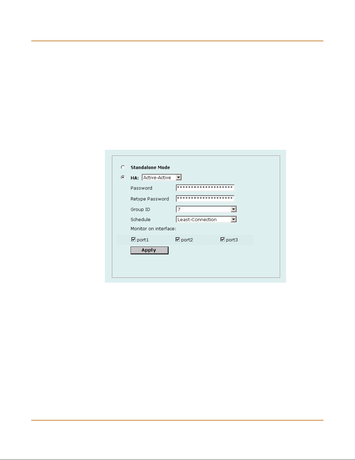
HA in NAT/Route mode High availability
8 Under Monitor on Interface, select the names of the interfaces to be monitored.
Monitor FortiGate interfaces to make sure they are functioning properly and that they
are connected to their networks. If a monitored interface fails or is disconnected from
its network, the FortiGate unit stops processing traffic and is removed from the cluster.
If you can re-establish traffic flow through the interface (for example, if you re-connect
a disconnected network cable) the FortiGate unit rejoins the cluster. You should only
monitor interfaces that are connected to networks.
9 Select Apply.
The FortiGate unit negotiates to establish an HA cluster. When you select apply you
may temporarily loose connectivity with the FortiGate unit as the HA cluster
negotiates.
Figure 13: Example Active-Active HA configuration
10 Repeat this procedure to add each FortiGate unit in the HA cluster.
When you have configured all of the FortiGate units, proceed to “Connecting the HA
cluster to your network”.
Connecting the HA cluster to your network
To connect the HA cluster to your network you must connect all matching interfaces in
the cluster to the same hub or switch. Then you must connect these interfaces to their
networks using the same hub or switch.
Also, you must connect all of the HA interfaces in the cluster to their own hub or
switch. You can also connect a management computer to this hub or switch. The units
in the cluster are constantly communicating HA status information to make sure the
cluster is functioning properly. For this reason, the connection between the HA ports of
all of the FortiGate units in the cluster must be well maintained. An interruption of this
communication can cause unpredictable results.
Switches are recommended for performance reasons.
80 Fortinet Inc.
Page 81
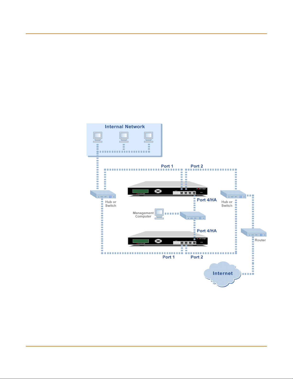
High availability HA in NAT/Route mode
The network equipment to use and the procedure to follow are the same, whether you
are configuring the FortiGate units for active-active HA or active-passive HA.
To connect the FortiGate units to your network:
1 Connect port 1 of each FortiGate unit to a switch or hub connected to your internal
network.
2 Connect port 2 of each FortiGate unit to a switch or hub connected to your external
network.
3 Optionally connect port 3 of each FortiGate unit to a switch or hub connected to
another network.
4 Connect the 4/HA interfaces of the FortiGate units to another switch or hub.
Figure 14: HA network configuration
When you have connected the cluster, proceed to “Starting the HA cluster”.
FortiGate-400 Installation and Configuration Guide 81
Page 82

HA in Transparent mode High availability
Starting the HA cluster
After all of the FortiGate units in the cluster are configured for HA and once the cluster
is connected, use the following procedure to start the HA cluster.
1 Power on all of the HA units in the cluster.
As the units power on they negotiate to choose the primary cluster unit and the
subordinate units. This negotiation occurs with no user intervention.
When negotiation is complete the cluster is ready to begin processing network traffic.
You can use the information in “Managing the HA cluster” on page 86 to log into and
manage the cluster.
HA in Transparent mode
Use the following steps to configure a group of FortiGate units to operate as an HA
cluster in Transparent mode.
• Installing and configuring the FortiGate units
• Configuring the HA interface and HA IP address
• Configuring the HA cluster
• Connecting the HA cluster to your network
• Starting the HA cluster
Installing and configuring the FortiGate units
Follow the instructions in “Transparent mode installation” on page 61 to install and
configure the FortiGate units. All of the FortiGate units in the HA cluster should have
the same configuration. Do not connect the FortiGate units to the network. Instead,
proceed to “Configuring the HA interface and HA IP address”.
Configuring the HA interface and HA IP address
Configure the 4/HA interfaces of all of the FortiGate-400s in the HA cluster to operate
in HA mode. When you switch the 4/HA interface to HA mode, the System > Config >
HA options become active. When running in HA mode, the 4/HA interfaces cannot be
connected to a network because they are dedicated to HA communication.
The 4/HA interface of each FortiGate-400 unit must be configured with a different IP
address. The addresses of the 4/HA interfaces must be on the same subnet and they
must be configured for management access.
Repeat the following procedure for each FortiGate unit in the HA cluster:
1 Connect to the FortiGate unit and log into the web-based manager.
2 Go to System > Network > Management.
3 For the port4/ha interface, select HA to configure port4/ha for HA operation.
4 Select the management Access methods for the port4/ha interface.
82 Fortinet Inc.
Page 83

High availability HA in Transparent mode
HTTPS To allow secure HTTPS connections to the web-based manager through this
PING If you want this interface to respond to pings. Use this setting to verify your
HTTP To allow HTTP connections to the web-based manager through this interface.
SSH To allow secure SSH connections to the CLI through this interface.
SNMP To allow a remote SNMP manager to request SNMP information by connecting to
TELNET To allow Telnet connections to the CLI through this interface. Telnet connections
interface.
installation and for testing.
HTTP connections are not secure and can be intercepted by a third party.
this interface.
are not secure and can be intercepted by a third party.
5 Change the HA IP address and Netmask as required.
6 Optionally configure management access for other interfaces.
7 Select Apply.
Now that you have configured the HA interfaces, proceed to “Configuring the HA
cluster”.
Configuring the HA cluster
Use the following procedure to configure each FortiGate unit for HA before connecting
the HA cluster to your network.
Note: These instructions describe configuring each of the FortiGate units in the HA cluster
before connecting the HA cluster to your network. You can also use the procedure “Connecting
the HA cluster to your network” on page 85 to connect the HA cluster to your network first.
1 Connect to the FortiGate unit and log into the web-based manager.
2 Go to System > Config > HA.
3 Select HA.
You can only select HA if the 4/HA interface is configured for HA operation. See
“Configuring the HA interface and HA IP address” on page 82.
4 Select the HA mode.
Select Active-Passive mode to create an Active-Passive HA cluster, in which one
FortiGate unit in the HA cluster is actively processing all connections and the others
are passively monitoring the status and remaining synchronized with the active
FortiGate unit.
Select Active-Active mode to create an Active-Active HA cluster, in which each
FortiGate unit in the HA cluster is actively processing connections and monitoring the
status of the other FortiGate units.
The HA mode must be the same for all FortiGate units in the HA cluster.
5 Enter and confirm a password for the HA cluster.
The password must be the same for all FortiGate units in the HA cluster.
6 Select a Group ID for the HA cluster.
The Group ID must be the same for all FortiGate units in the HA cluster.
FortiGate-400 Installation and Configuration Guide 83
Page 84

HA in Transparent mode High availability
7 If you are configuring Active-Active HA, select a schedule.
The schedule controls load balancing among the FortiGate units in the active-active
HA cluster. The schedule must be the same for all FortiGate units in the HA cluster.
None No load balancing. Select None when the cluster interfaces are
Hub Load balancing for hubs. Select Hub if the cluster interfaces are
Least Connection Least connection load balancing. If the FortiGate units are connected
Round Robin Round robin load balancing. If the FortiGate units are connected using
Weighted Round
Robin
Random Random load balancing. If the FortiGate units are connected using
IP Load balancing according to IP address. If the FortiGate units are
IP Port Load balancing according to IP address and port. If the FortiGate units
connected to load balancing switches.
connected to a hub. Traffic is distributed to units in a cluster based on
the Source IP and Destination IP of the packet.
using switches, select Least connection to distribute traffic to the cluster
unit with the fewest concurrent connections.
switches, select round robin to distribute traffic to the next available
cluster unit.
Weighted round robin load balancing. Similar to round robin, but
weighted values are assigned to each of the units in a cluster based on
their capacity and on how many connections they are currently
processing. For example, the primary unit should have a lower weighted
value because it handles scheduling and forwards traffic. Weighted
round robin distributes traffic more evenly because units that are not
processing traffic will be more likely to receive new connections than
units that are very busy.
switches, select random to randomly distribute traffic to cluster units.
connected using switches, select IP to distribute traffic to units in a
cluster based on the Source IP and Destination IP of the packet.
are connected using switches, select IP Port to distribute traffic to units
in a cluster based on the Source IP, Source Port, Destination IP, and
Destination port of the packet.
8 Under Monitor on Interface, select the names of the interfaces to be monitored.
Monitor FortiGate interfaces to make sure they are functioning properly and that they
are connected to their networks. If a monitored interface fails or is disconnected from
its network, the FortiGate unit stops processing traffic and is removed from the cluster.
If you can re-establish traffic flow through the interface (for example, if you re-connect
a disconnected network cable) the FortiGate unit rejoins the cluster. You should only
monitor interfaces that are connected to networks.
9 Select Apply.
The FortiGate unit negotiates to establish an HA cluster. When you select apply you
may temporarily loose connectivity with the FortiGate unit as the HA cluster
negotiates.
84 Fortinet Inc.
Page 85
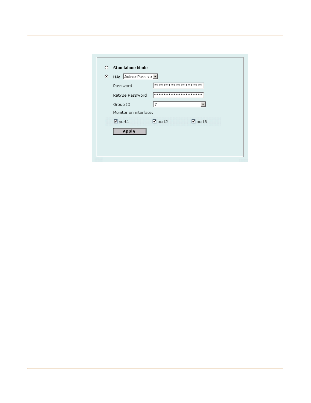
High availability HA in Transparent mode
Figure 15: Sample active-passive HA configuration
10 Repeat this procedure to add each FortiGate unit in the HA cluster.
When you have configured all of the FortiGate units, proceed to “Connecting the HA
cluster to your network”.
Connecting the HA cluster to your network
To connect the HA cluster to your network you must connect all matching interfaces in
the cluster to the same hub or switch. Then you must connect these interfaces to their
networks using the same hub or switch.
Also, you must connect all of the HA interfaces in the cluster to their own hub or
switch. You can also connect a management computer to this hub or switch. The units
in the cluster are constantly communicating HA status information to make sure the
cluster is functioning properly. For this reason, the connection between the HA ports of
all of the FortiGate units in the cluster must be well maintained. An interruption of this
communication can cause unpredictable results.
Switches are recommended for better performance.
The network equipment to use and the procedure to follow are the same, whether you
are configuring the FortiGate units for active-active HA or active-passive HA.
To connect the FortiGate units to your network:
1 Connect port 1 of each FortiGate unit to a switch or hub connected to your internal
network.
2 Connect port 2 of each FortiGate unit to a switch or hub connected to your external
network.
3 Optionally connect port 3 of each FortiGate unit to a switch or hub connected to
another network.
4 Connect the 4/HA interfaces of the FortiGate units to another switch or hub.
When you have connected the cluster, proceed to “Starting the HA cluster”.
FortiGate-400 Installation and Configuration Guide 85
Page 86

Managing the HA cluster High availability
Starting the HA cluster
After all of the FortiGate units in the cluster are configured for HA and once the cluster
is connected, use the following procedure to start the HA cluster.
1 Power on all of the HA units in the cluster.
As the units power on they negotiate to choose the primary cluster unit and the
subordinate units. This negotiation occurs with no user intervention.
When negotiation is complete the cluster is ready to begin processing network traffic.
You can use the information in “Managing the HA cluster” on page 86 to log into and
manage the cluster.
Managing the HA cluster
When a FortiGate cluster is up and running, you manage it as a cluster instead of a
group of individual FortiGate units. You manage the cluster by connecting to the
web-based manager or CLI using any interface configured for management access.
Since all units in the cluster are configured with the same interface IP addresses
(except for the HA interface), connecting to any interface IP address configured for
management access connects to that cluster interface; which automatically connects
you to the primary FortiGate unit.
You can also connect to and manage individual units in the cluster by connecting to
their HA interfaces (all of which are configured with a different IP address).
You can also manage individual cluster units by connect to the primary unit CLI. From
here you can use the execute ha manage command to connect to the CLI of each
unit in the cluster.
This section describes:
• Viewing the status of cluster members
• Monitoring cluster members
• Monitoring cluster sessions
• Viewing and managing cluster log messages
• Managing individual cluster units
• Synchronizing the cluster configuration
• Returning to standalone configuration
• Replacing a FortiGate unit after fail-over
Viewing the status of cluster members
To view the status of each cluster member.
1 Connect to the cluster and log into the web-based manager.
2 Go to System > Status > Cluster Members.
The web-based manager lists the serial numbers of all of the FortiGate units in the
cluster. The primary unit is identified as Local. For each cluster member, the list
includes the up time and status for that cluster member.
86 Fortinet Inc.
Page 87
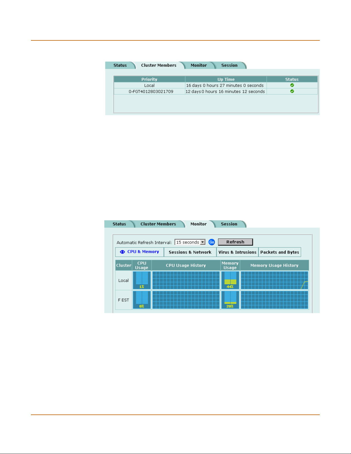
High availability Managing the HA cluster
Figure 16: Example cluster members list
Monitoring cluster members
To monitor health information for each cluster member.
1 Connect to the cluster and log into the web-based manager.
2 Go to System > Status > Monitor.
CPU, Memory Status, and Hard disk status is displayed for each cluster member. The
primary unit is identified as Local and the other units in the cluster are listed by serial
number.
The display includes bar graphs of current CPU and memory usage as well as line
graphs of CPU and memory usage for the last minute.
For more information, see “Viewing CPU and memory status” on page 110.
Figure 17: Example cluster Sessions & Network display
3 Select Sessions & Network.
Sessions and network status is displayed for each cluster member. The primary unit is
identified as Local and the other units in the cluster are listed by serial number.
The display includes bar graphs of the current number of sessions and current
network utilization as well as line graphs of session and network utilization usage for
the last minute. The line graph scales are shown in the upper left corner of the graph.
For more information, see “Viewing sessions and network status” on page 111.
FortiGate-400 Installation and Configuration Guide 87
Page 88

Managing the HA cluster High availability
4 Select Virus & Intrusions.
Virus and intrusions status is displayed for each cluster member. The primary unit is
identified as Local and the other units in the cluster are listed by serial number.
The display includes bar graphs of the number viruses and intrusions detected per
hour as well as line graphs of the number of viruses and intrusions detected for the
last 20 hours.
For more information, see “Viewing virus and intrusions status” on page 112.
5 Select Packets & Bytes.
The number of packets and bytes processed by each cluster member is displayed.
6 For each of these displays you can set the automatic refresh interval and select Go to
control how often the web-based manager updates the display.
More frequent updates use system resources and increase network traffic. However,
this only occurs when you are viewing the display using the web-based manager. The
line graph scales are shown on the upper right corner of the graph.
Monitoring cluster sessions
To view the current primary unit communication sessions.
1 Connect to the cluster and log into the web-based manager.
2 Go to System > Status > Session.
The session table displays the sessions processed by the primary unit in the cluster.
The sessions include HA communications between the primary unit and the
subordinate units.
Viewing and managing cluster log messages
To view log messages for each cluster member:
1 Connect to the cluster and log into the web-based manager.
2 Go to Log&Report > Logging.
The primary unit Traffic log, Event log, Attack log, Antivirus log, Web Filter log, and
Email Filter log are displayed.
The pull-down list at the upper right of the display identifies the unit for which logs are
displayed. The primary unit is identified as Local and the other units in the cluster are
listed by serial number.
3 Select the serial number of one of the units in the cluster to display the logs for this
cluster unit.
You can view logs saved to memory or logs saved to the hard disk, depending on the
configuration of the cluster unit.
4 For each cluster unit:
• You can view and search log messages (see “Viewing logs saved to memory” on
page 289 and “Viewing and managing logs saved to the hard disk” on page 290)
• If the cluster unit contains a hard disk you can manage log messages (see
“Downloading a log file to the management computer” on page 291, “Deleting all
messages in an active log” on page 291, and “Deleting a saved log file” on
page 292)
88 Fortinet Inc.
Page 89

High availability Managing the HA cluster
Note: Note you can view and manage log messages for all cluster members. However, from the
primary unit you can only configure logging for the primary unit. To configure logging for other
units in the cluster you must manage individual cluster units.
Managing individual cluster units
You can manage individual cluster units by connecting to each unit’s HA interface
using either the web-based manager or the CLI. To do this, the HA interfaces of each
unit have to be configured for HTTPS and SSH management access.
You can also use the following procedure to connect to the CLI of each unit in the
cluster:
Managing individual units from the web-based manager:
1 Use SSH to connect to the cluster and log into the web-based manager.
Connect to any cluster interface configured for SSH management to automatically log
into the primary unit.
You can also use a direct cable connection to log into the primary unit CLI (to do this
you must know which unit is the primary unit. See “Selecting a FortiGate unit to a
permanent primary unit” on page 91 to control which FortiGate unit becomes the
primary unit).
2 Enter the following command followed by a space and type a question mark (?):
execute ha manage
A list of all of the subordinate units in the cluster is displayed. Each cluster unit in the
list is numbered, starting at 1. The information displayed for each cluster unit includes
the unit serial number and host name of the unit.
3 Complete the command with the number of the subordinate unit to log into. For
example, to log into subordinate unit 1, enter the following command:
execute ha manage 1
You are connected to and logged into the CLI of the selected subordinate unit. If this
subordinate unit has a different host name, the CLI prompt changes to this host name.
You can use CLI commands to manage this subordinate unit.
4 Enter the following command to return to the primary unit CLI:
exit
You can use the execute manage ha command to log into the CLI of any of the
other subordinate units in the cluster.
Synchronizing the cluster configuration
For best results when operating a cluster you should make sure that the
configurations of all of the units in the cluster remain synchronized. You can do this by
making configuration changes to the primary unit and then using the execute ha
synchronize command from each subordinate unit in an HA cluster to manually
synchronize its configuration with the primary unit. Using this command you can
synchronize the following:
FortiGate-400 Installation and Configuration Guide 89
Page 90

Managing the HA cluster High availability
Table 16: execute ha synchronize keywords
Keyword Description
config Synchronize the FortiGate configuration. This includes normal system
avupd Synchronize the antivirus engine and antivirus definitions received by the
attackdef Synchronize NIDS attack definition updates received by the primary unit from
weblists Synchronize web filter lists added to or changed on the primary unit.
emaillists Synchronize email filter lists added to or changed on the primary unit.
resmsg Synchronize replacement messages changed on the primary unit.
ca Synchronize CA certificates added to the primary unit.
localcert Synchronize local certificates added to the primary unit.
all Synchronize all of the above.
configuration, firewall configuration, VPN configuration and so on stored in the
FortiGate configuration file.
primary unit from the FortiResponse Distribution Network (FDN).
the FDN.
Use the following procedure to make configuration changes to the primary FortiGate
unit and then synchronize the configuration of the subordinate units.
1 Connect to the cluster and log into the web-based manager or CLI.
2 Make configuration changes as required.
3 Connect to the CLI of each of the subordinate units in the cluster.
To connect to subordinate units, see “Managing individual cluster units” on page 89.
4 Use the execute ha synchronize command to synchronize the configuration of
the subordinate unit.
5 Repeat steps 3 and 4 for all of the subordinate units in the HA cluster.
Returning to standalone configuration
Repeat this procedure for each FortiGate unit in the HA cluster. To return to
standalone configuration:
1 Connect to the web-based manager.
2 Go to System > Config > HA.
3 Select Standalone Mode and select Apply.
The FortiGate unit exits from HA mode and returns to standalone mode.
Replacing a FortiGate unit after fail-over
A failover can occur due to a hardware or software problem. When a failover occurs,
you can attempt to restart the failed FortiGate unit by cycling its power. If the FortiGate
unit starts up correctly, it rejoins the HA cluster, which then continues to function
normally. If the FortiGate unit does not restart normally or does not rejoin the HA
cluster, you must take it out of the network and either reconfigure or replace it.
Once the FortiGate unit is reconfigured or replaced, change its HA configuration to
match that of the FortiGate unit that failed and connect it back into the network. The
reconnected FortiGate unit then automatically joins the HA cluster.
90 Fortinet Inc.
Page 91

High availability Advanced HA options
Advanced HA options
The following advanced HA options are available from the FortiGate CLI:
• Selecting a FortiGate unit to a permanent primary unit
• Configuring weighted-round-robin weights
Selecting a FortiGate unit to a permanent primary unit
In a typical FortiGate cluster configuration, the primary unit selection process is
automatic. The primary unit can be different each time the cluster starts up. In addition
the unit functioning as the primary unit can change from time to time (for example, if
the current primary unit restarts, one of the other units in the cluster replaces it as the
primary unit).
In some situations, you may want to control which unit becomes the primary unit. You
can configure a FortiGate unit to become the permanent primary unit by changing the
priority of this unit and configuring it to override any other primary unit.
When FortiGates units in a cluster are negotiating to be the primary unit, the one with
the lowest priority always becomes the primary unit. If two units have the same
priority, the standard negotiation process is used to select the primary unit.
To configure a FortiGate unit to be the permanent primary unit in an HA cluster:
1 Connect to the CLI of the permanent primary FortiGate unit.
2 Set the priority of the permanent primary unit. Enter:
set system ha priority <priority_int>
Where <priority_int> is the priority to set for the permanent primary unit. The unit
with the lowest priority becomes the primary unit. The default priority is 128. Set the
priority of the permanent primary unit to a number lower than 128.
For example, to set the priority of the permanent primary unit to 10, enter the
command:
set system ha priority 10
3 Make sure the priorities of all of the other units in the cluster are higher than the
priority of the permanent primary unit.
The command get system ha mode displays the current priority of the FortiGate
unit that you are connected to.
4 Configure the permanent primary unit to override an existing primary unit when it joins
the cluster. Use the following command to configure primary unit override:
set system ha override enable
Enable override so the that the permanent primary unit will always override any other
primary unit. For example, if the permanent primary unit shuts down, one of the other
units in the cluster replaces it as the primary unit. When the permanent primary unit is
restarted, it can become the primary unit again only if override is enabled.
FortiGate-400 Installation and Configuration Guide 91
Page 92

Advanced HA options High availability
Configuring weighted-round-robin weights
By default, in active-active HA mode the weighted round-robin schedule assigns the
same weight to each FortiGate unit in the cluster. Once the cluster is configured to use
the weighted round-robin schedule, you can use the set system ha weight
command to configure a weight value for each cluster unit. The weight value sets the
maximum number of connections that are sent to a cluster unit before a connection
can be sent to the next cluster unit. You can set weight values to control the number of
connections processed by each cluster unit. One use for this technique would be to
reduce the number of connections processed by the primary cluster unit, by
increasing the weight assigned to the subordinate cluster units.
Weight values are entered in order according to the priority of the units in the cluster.
For example, if you have a cluster of 3 FortiGate units, you can enter the following
command to configure the weight values for each unit:
set system ha weight 1 3 3
This command has the following results:
• The first connection is processed by the primary unit
• The next three connections are processed by the first subordinate unit
• The next three connections are processed by the second subordinate unit
The subordinate units will process more connections than the primary unit, and both
subordinate units will on average process the same number of connections.
92 Fortinet Inc.
Page 93

FortiGate-400 Installation and Configuration Guide Version 2.50 MR2
System status
You can connect to the web-based manager and go to System > Status to view the
current status of your FortiGate unit. The status information that is displayed includes
the current firmware version, the current virus and attack definitions, and the FortiGate
unit serial number.
If you have logged into the web-based manager using the admin administrator
account, you can use System Status to make any of the following changes to the
FortiGate system settings:
• Changing the FortiGate host name
• Changing the FortiGate firmware
• Manual virus definition updates
• Manual attack definition updates
• Backing up system settings
• Restoring system settings
• Restoring system settings to factory defaults
• Changing to Transparent mode
• Changing to NAT/Route mode
• Restarting the FortiGate unit
• Shutting down the FortiGate unit
If you log into the web-based manager with any other administrator account, you can
go to System > Status to view the system settings including:
• Displaying the FortiGate serial number
• Displaying the FortiGate up time
• Displaying log hard disk status
All administrative users can also go to System > Status > Monitor and view
FortiGate system status. System status displays FortiGate health monitoring
information including CPU and memory status, Session and network status.
• System status
All administrative users can also go to System > Status > Session and view the
active communication sessions to and through the FortiGate unit.
• Session list
FortiGate-400 Installation and Configuration Guide 93
Page 94

Changing the FortiGate host name System status
Changing the FortiGate host name
The FortiGate host name appears on the System > Status page and on the FortiGate
CLI prompt. The host name is also used as the SNMP System Name (see
“Configuring SNMP” on page 162).
The default host name is FortiGate-400.
To change the FortiGate host name:
1 Go to System > Status.
2 Select Edit Host Name .
3 Enter a new host name.
4 Select OK.
The new host name appears on the System Status page and is added to the SNMP
System Name.
Changing the FortiGate firmware
After you download a FortiGate firmware image from Fortinet, you can use the
procedures in Tab le 1 to install the firmware image on your FortiGate unit.
Table 1: Firmware upgrade procedures
Procedure Description
Upgrade to a new
firmware version
Revert to a previous
firmware version
Install a firmware
image from a system
reboot using the CLI
Test a new firmware
image before
installing it
Installing and using a
backup firmware
image
Commonly-used web-based manager and CLI procedures to
upgrade to a new FortiOS firmware version or to a more recent
build of the same firmware version.
Use the web-based manager or CLI procedure to revert to a
previous firmware version. This procedure reverts your FortiGate
unit to its factory default configuration.
Use this procedure to install a new firmware version or revert to a
previous firmware version. You must run this procedure by
connecting to the CLI using the FortiGate console port and a nullmodem cable. This procedure reverts your FortiGate unit to its
factory default configuration.
Use this procedure to test a new firmware image before installing it.
You must run this procedure by connecting to the CLI using the
FortiGate console port and a null-modem cable. This procedure
temporarily installs a new firmware image using your current
configuration. You can test the firmware image before installing it
permanently. If the firmware image works correctly you can use
one of the other procedures listed in this table to install it
permanently.
If your FortiGate unit is running BIOS version v3.x, you can install a
backup firmware image. Once the backup firmware image is
installed you can switch to this backup image when required.
94 Fortinet Inc.
Page 95

System status Changing the FortiGate firmware
Upgrade to a new firmware version
Use the following procedures to upgrade your FortiGate to a newer firmware version.
Upgrading the firmware using the web-based manager
Note: Installing firmware replaces your current antivirus and attack definitions with the
definitions included with the firmware release that you are installing. When you have installed
new firmware, use the procedure “Manually updating antivirus and attack definitions” on
page 119 to make sure that antivirus and attack definitions are up-to-date.
1 Copy the firmware image file to your management computer.
2 Login to the FortiGate web-based manager as the admin administrative user.
3 Go to System > Status.
4 Select Firmware Upgrade .
5 Enter the path and filename of the firmware image file, or select Browse and locate the
file.
6 Select OK.
The FortiGate unit uploads the firmware image file, upgrades to the new firmware
version, restarts, and displays the FortiGate login. This process takes a few minutes.
7 Login to the web-based manager.
8 Go to System > Status and check the Firmware Version to confirm that the firmware
upgrade has been installed successfully.
9 Use the procedure “Manually updating antivirus and attack definitions” on page 119 to
update antivirus and attack definitions.
Upgrading the firmware using the CLI
To use the following procedure you must have a TFTP server that you can connect to
from the FortiGate unit.
Note: Installing firmware replaces your current antivirus and attack definitions with the
definitions included with the firmware release that you are installing. When you have installed
new firmware, use the procedure “Manually updating antivirus and attack definitions” on
page 119 to make sure that antivirus and attack definitions are up-to-date. You can also use the
CLI command
definitions.
1 Make sure that the TFTP server is running.
2 Copy the new firmware image file to the root directory of the TFTP server.
3 Log into the CLI as the admin administrative user.
4 Make sure the FortiGate unit can connect to the TFTP server.
You can use the following command to ping the computer running the TFTP server.
For example, if the TFTP server's IP address is 192.168.1.168:
execute ping 192.168.1.168
execute updatecenter updatenow to update the antivirus and attack
FortiGate-400 Installation and Configuration Guide 95
Page 96

Changing the FortiGate firmware System status
5 Enter the following command to copy the firmware image from the TFTP server to the
FortiGate:
execute restore image <name_str> <tftp_ip>
Where <name_str> is the name of the firmware image file on the TFTP server and
<tftp_ip> is the IP address of the TFTP server. For example, if the firmware image
file name is FGT_300-v250-build045-FORTINET.out and the IP address of the
TFTP server is 192.168.1.168, enter:
execute restore image FGT_300-v250-build045-FORTINET.out
192.168.1.168
The FortiGate unit uploads the firmware image file, upgrades to the new firmware
version, and restarts. This process takes a few minutes.
6 Reconnect to the CLI.
7 To confirm that the new firmware image has been loaded, enter:
get system status
8 Use the procedure “Manually updating antivirus and attack definitions” on page 119 to
update antivirus and attack definitions, or from the CLI, enter:
execute updatecenter updatenow
9 To confirm that the antivirus and attack definitions have been updated, enter the
following command to display the antivirus engine, virus and attack definitions version,
contract expiry, and last update attempt information.
get system objver
Revert to a previous firmware version
Use the following procedures to revert your FortiGate unit to a previous firmware
version.
Reverting to a previous firmware version using the web-based manager
The following procedures return your FortiGate unit to its factory default configuration
and delete NIDS user-defined signatures, web content lists, email filtering lists, and
changes to replacement messages.
Before running this procedure you can:
• Backup the FortiGate unit configuration, use the procedure “Backing up system
settings” on page 108.
• Backup the NIDS user defined signatures, see the FortiGate NIDS Guide
• Backup web content and email filtering lists, see the FortiGate Content Protection
Guide.
If you are reverting to a previous FortiOS version (for example, reverting from FortiOS
v2.50 to FortiOS v2.36) you may not be able to restore your previous configuration
from the backup configuration file.
96 Fortinet Inc.
Page 97

System status Changing the FortiGate firmware
Note: Installing firmware replaces your current antivirus and attack definitions with the
definitions included with the firmware release that you are installing. When you have installed
new firmware, use the procedure “Manually updating antivirus and attack definitions” on
page 119 to make sure that antivirus and attack definitions are up-to-date.
1 Copy the firmware image file to your management computer.
2 Login to the FortiGate web-based manager as the admin administrative user.
3 Go to System > Status.
4 Select Firmware Upgrade .
5 Enter the path and filename of the previous firmware image file, or select Browse and
locate the file.
6 Select OK.
The FortiGate unit uploads the firmware image file, reverts to the old firmware version,
resets the configuration, restarts, and displays the FortiGate login. This process takes
a few minutes.
7 Login to the web-based manager.
For information about logging into the web-based manager when the FortiGate unit is
set to factory defaults, see “Connecting to the web-based manager” on page 32.
8 Go to System > Status and check the Firmware Version to confirm that the firmware
has been installed successfully.
9 Restore your configuration.
See “Restoring system settings” on page 108 to restore your previous configuration.
10 Use the procedure “Manually updating antivirus and attack definitions” on page 119 to
update antivirus and attack definitions.
Reverting to a previous firmware version using the CLI
This procedure reverts your FortiGate unit to its factory default configuration and
deletes NIDS user-defined signatures, web content lists, email filtering lists, and
changes to replacement messages.
Before running this procedure you can:
• Backup the FortiGate unit configuration using the command execute backup
config.
• Backup the NIDS user defined signatures using the command execute backup
nidsuserdefsig
• Backup web content and email filtering lists, see the FortiGate Content Protection
Guide.
If you are reverting to a previous FortiOS version (for example, reverting from FortiOS
v2.50 to FortiOS v2.36) you may not be able to restore your previous configuration
from the backup configuration file.
FortiGate-400 Installation and Configuration Guide 97
Page 98

Changing the FortiGate firmware System status
Note: Installing firmware replaces your current antivirus and attack definitions with the
definitions included with the firmware release that you are installing. When you have installed
new firmware, use the procedure “Manually updating antivirus and attack definitions” on
page 119 to make sure that antivirus and attack definitions are up-to-date. You can also use the
CLI command
definitions.
execute updatecenter updatenow to update the antivirus and attack
To use the following procedure you must have a TFTP server that you can connect to
from the FortiGate unit.
1 Make sure that the TFTP server is running.
2 Copy the new firmware image file to the root directory of the TFTP server.
3 Login to the FortiGate CLI as the admin administrative user.
4 Make sure the FortiGate unit can connect to the TFTP server.
You can use the following command to ping the computer running the TFTP server.
For example, if the TFTP server's IP address is 192.168.1.168:
execute ping 192.168.1.168
5 Enter the following command to copy the firmware image from the TFTP server to the
FortiGate unit:
execute restore image <name_str> <tftp_ip>
Where <name_str> is the name of the firmware image file on the TFTP server and
<tftp_ip> is the IP address of the TFTP server. For example, if the firmware image
file name is FGT_300-v250-build045-FORTINET.out and the IP address of the
TFTP server is 192.168.1.168, enter:
execute restore image FGT_300-v250-build045-FORTINET.out
192.168.1.168
The FortiGate unit uploads the firmware image file. Once the file has been uploaded a
message similar to the following is displayed:
Get image from tftp server OK.
This operation will downgarde the current firmware version!
Do you want to continue? (y/n)
6 Type Y
7 The FortiGate unit reverts to the old firmware version, resets the configuration to
factory defaults, and restarts. This process takes a few minutes.
8 Reconnect to the CLI.
For information about logging into the web-based manager when the FortiGate unit is
set to factory defaults, see “Connecting to the command line interface (CLI)” on
page 33.
9 To confirm that the new firmware image has been loaded, enter:
get system status
10 Restore your previous configuration. Use the following command:
execute restore config
11 Use the procedure “Manually updating antivirus and attack definitions” on page 119 to
update antivirus and attack definitions, or from the CLI, enter:
execute updatecenter updatenow
98 Fortinet Inc.
Page 99

System status Changing the FortiGate firmware
12 To confirm that the antivirus and attack definitions have been updated, enter the
following command to display the antivirus engine, virus and attack definitions version,
contract expiry, and last update attempt information.
get system objver
Install a firmware image from a system reboot using the CLI
This procedure installs a specified firmware image and resets the FortiGate unit to
default settings. You can use this procedure to upgrade to a new firmware version,
revert to an older firmware version, or to re-install the current firmware.
Note: There are a few variations on this procedure for different FortiGate BIOS versions. These
variations are explained in the procedure steps that are affected. The version of the BIOS
running on your FortiGate unit is displayed when you restart the FortiGate unit while accessing
the CLI by connecting to the FortiGate console port using a null-modem cable.
To run this procedure you:
• access the CLI by connecting to the FortiGate console port using a null-modem
cable,
• install a TFTP server that you can connect to from port1. The TFTP server should
be on the same subnet as port1.
Before running this procedure you can:
• Backup the FortiGate unit configuration, use the procedure “Backing up system
settings” on page 108.
• Backup the NIDS user defined signatures, see the FortiGate NIDS Guide
• Backup web content and email filtering lists, see the FortiGate Content Protection
Guide.
If you are reverting to a previous FortiOS version (for example, reverting from FortiOS
v2.50 to FortiOS v2.36) you may not be able to restore your previous configuration
from the backup configuration file.
Note: Installing firmware replaces your current antivirus and attack definitions with the
definitions included with the firmware release that you are installing. When you have installed
new firmware, use the procedure “Manually updating antivirus and attack definitions” on
page 119 to make sure that antivirus and attack definitions are up-to-date.
To install firmware from a system reboot
1 Connect to the CLI using the null modem cable and FortiGate console port.
2 Make sure that the TFTP server is running.
3 Copy the new firmware image file to the root directory of your TFTP server.
4 Make sure that port1 is connected to the same network as the TFTP server.
5 To confirm that the FortiGate unit can connect to the TFTP server, use the following
command to ping the computer running the TFTP server. For example, if the TFTP
server’s IP address is 192.168.1.168:
execute ping 192.168.1.168
FortiGate-400 Installation and Configuration Guide 99
Page 100

Changing the FortiGate firmware System status
6 Enter the following command to restart the FortiGate unit:
execute reboot
As the FortiGate units starts, a series of system startup messages are displayed.
When one of the following messages appears:
• FortiGate unit running v2.x BIOS
Press Any Key To Download Boot Image.
...
• FortiGate unit running v3.x BIOS
Press any key to enter configuration menu.....
......
7 Immediately press any key to interrupt the system startup.
I
Note: You only have 3 seconds to press any key. If you do not press any key soon enough, the
FortiGate unit reboots and you must log in and repeat the
execute reboot command.
If you successfully interrupt the startup process, one of the following messages
appears:
• FortiGate unit running v2.x BIOS
Enter TFTP Server Address [192.168.1.168]:
Go to step 9.
• FortiGate unit running v3.x BIOS
[G]: Get firmware image from TFTP server.
[F]: Format boot device.
[B]: Boot with backup firmware and set as default.
[Q]: Quit menu and continue to boot with default firmware.
[H]: Display this list of options.
Enter G,F,B,Q,or H:
8 Type G to get the new firmware image from the TFTP server.
9 Type the address of the TFTP server and press Enter.
The following message appears:
Enter Local Address [192.168.1.188]:
10 Type the address of port1 and press Enter.
Note: The local IP address is only used to download the firmware image. After the firmware is
installed the address of this interface is changed back to the default IP address for this interface.
The following message appears:
Enter File Name [image.out]:
100 Fortinet Inc.
 Loading...