

Page 1
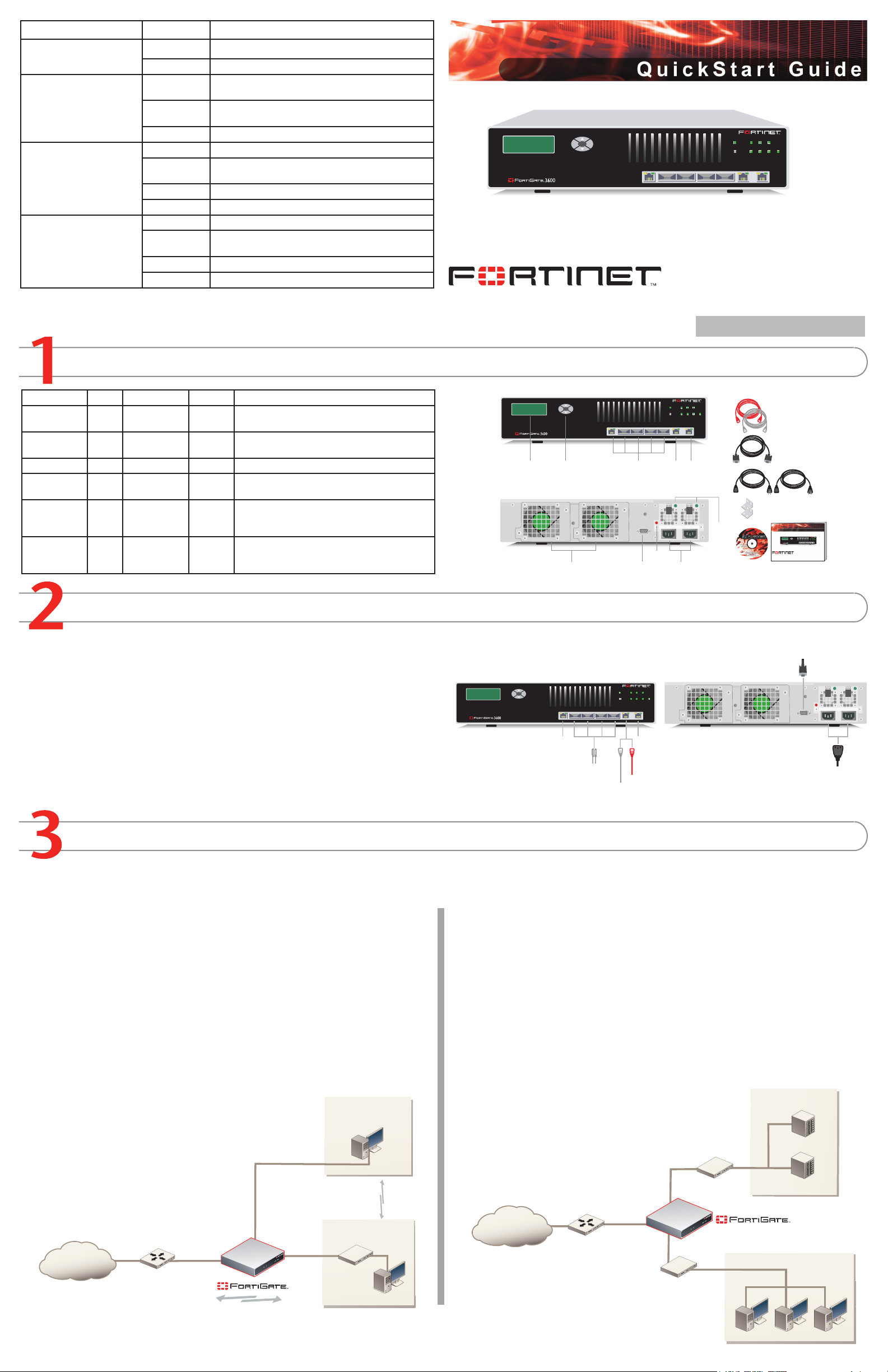
Checking the Package Contents
Connecting
Planning the Configuration
Internet
Router
Internal
network
Port 1
10.10.10.1
10.10.10.2
Internal Net wo rk
192.168.1.3
Internal
192.168.1.99
Routing policies controlling
traffic between internal
networks.
External
204.23.1.5
NAT mode policies controlling
traffic between internal
and external networks.
Internet
Router
DMZ net
w
ork
Web Server
Mail Server
Internal
network
Hub or switch
Port 1
External
Internal
Esc Enter
POWER
Hi-Temp 4
1 2
3
5/HA
INT
EXT
1
2
3 4 5/HA
INTERNAL EXTERNAL
Esc Enter
POWER
Hi-Temp 4
1 2
3
5/HA
INT
EXT
1
2
3 4 5/HA
INTERNAL EXTERNAL
Fron t
Back
Power Cables (2)
Rack-M ount Bracke ts
Null-M odem Cable
(RS-23 2)
Ethern et Cables:
Orange - Crossove r
Grey - Straight-t hrough
LCD
Displ ay
Contr ol
Butto ns
1, 2, 3, 4, 5/HA
Inter faces
Inter nal
Inter face
Exter nal
Inter face
RS-23 2 Seri al
Conne ction
Redun dant
Hot S wappab le
Power Suppl ies
Redun dant
Hot-S wappab le
Fan Asse mblie s
Power
Suppl y
LEDs
Alarm
Cance l
Butto n
Docume ntation
FortiGate-3600
Copyright 2006 Fortinet Incorporat ed. All rig hts reserve d.
Trademarks
Products mentioned in t his documen t are trade marks.
Qu i ck S ta r t G u i de
Esc Enter
POWER
Hi-Temp 4
1 2
3
5/HA
INT
EXT
123 4 5/HA INTERNAL EXTERNAL
Esc Enter
POWER
Hi-Temp 4
1 2
3
5/HA
INT
EXT
1
2
3 4 5/HA
INTERNAL EXTERNAL
Optio nal n ull modem cable conne cts
to se rial port on manageme nt co mpute r
Power cabl es connect to po wer o utlet s
Cross over Ethernet cable
conn ects to management co mpute r on inter nal network
Strai ght-t hrough Ethernet cable conn ects to LAN or switch on i ntern al ne twork
or
SC fi ber o ptic cables
conn ect t o other networks
Strai ght-t hrough Ethernet cable
conn ects
to In terne t (public switch , rou ter o r mod em)
Strai ght-t hrough Ethernet cable
conn ects
to an other network
LED State Description
Power
Display Panel LEDs:
1, 2, 3, 4
5/HA, INT, EXT
Port 1
Internal, External
Green The FortiGate unit is on.
Off The FortiGate unit is off.
Green The correct cable is in use and the connected equip-
ment has power.
Flashing
Network activity at this interface.
Green
Off No link established.
Amber The link is up.
Flashing
Network activity at this interface.
Amber
Green Link speed is 100Mb/s
Off Link speed is 10Mb/s
Amber The link is up.
Flashing
Network activity at this interface.
Amber
Green Link speed is 1000Mb/s
Off Link speed is 100Mb/s
© Copyright 2009 Fortinet Incorporated. All rights reserved.
Products mentioned in this document are trademarks or registered trademarks of their respective holders.
Regulatory Compliance
FCC Class A Part 15 CSA/CUS
23 January 2009
FortiGate-3600
01-30006-0041-20090123
Connector Type Speed Protocol Description
Internal SC 1000Base-SX Ethernet Copper gigabit connection to the internal
network.
External SC 1000Base-SX Ethernet Copper gigabit connection to the internet.
Port 1 RJ-45 10/100Base-T Ethernet Optional connection to a 10/100Base-T network.
Port 2 to 4 SC 1000Base-SC Ethernet Optional multimode ber optic connections to
other networks.
Port 5/HA SC 1000Base-SC Ethernet Optional multimode ber optic connection to an-
other network, or to other FortiGate-3600 units
for high availability (HA).
CONSOLE DB-9 9600 bps RS-232
serial
Optional connection to the management computer. Provides access to the command line
interface (CLI).
Connect the FortiGate unit to a power outlet and to the internal and external networks.
Place the unit on a stable surface.
•
The FortiGate unit requires 1.5 inches (3.75 cm) clearance above and on each side to
•
allow for cooling.
Make sure the power switch on the back of the unit is turned off before connecting the
•
power and network cables.
MAIN MENU appears when the unit is up and running.
•
If only one power supply is connected, an audible alarm sounds to indicate a failed
•
power supply. To stop this alarm, press the red alarm cancel button.
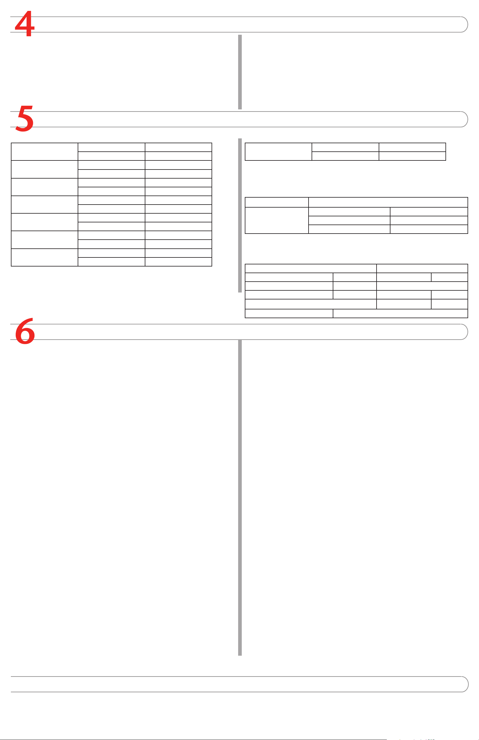
Before beginning to congure the FortiGate unit, you need to plan how to integrate the unit into your network. Your conguration plan is dependent upon the operating mode that you select:
NAT/Route mode (the default) or Transparent mode. Refer to the Documentation CD-ROM for information on how to control trafc, and how to congure HA, antivirus protection, FortiGuard,
Web content ltering, Spam ltering, intrusion prevention (IPS), and virtual private networking (VPN).
NAT/Route mode
In NAT/Route mode, each FortiGate unit is visible to the network that it is connected to. All
of its interfaces are on different subnets. Each interface connected to a network must be
congured with an IP address that is valid for that network.
You would typically use NAT/Route mode when the FortiGate unit is deployed as a gateway
between private and public networks. In its default NAT/Route mode conguration, the unit
functions as a rewall. Firewall policies control communications through the FortiGate unit.
No trafc can pass through the FortiGate unit until you add rewall policies.
Transparent mode
In Transparent mode, the FortiGate unit is invisible to the network. All of its interfaces are on
the same subnet. You only have to congure a management IP address so that you can make
conguration changes.
You would typically use the FortiGate unit in Transparent mode on a private network behind
an existing rewall or behind a router. In its default Transparent mode conguration, the unit
functions as a rewall. No trafc can pass through the FortiGate unit until you add rewall
policies.
In NAT/Route mode, rewall policies can operate in NAT mode or in Route mode. In NAT
mode, the FortiGate unit performs network address translation before IP packets are sent to
You can connect up to four network segments to the FortiGate unit to control trafc between
these network segments.
the destination network. In Route mode, no translation takes place.
Page 2
Completing the Configuration
7
Collecting Information
Configuring the FortiGate Unit
Choosing a Configuration Tool
Web-based manager
Command Line Interface (CLI)
The FortiGate web-based manager is an easy to use management tool.
Use it to congure the administrator password, the interface and default gateway addresses,
and the DNS server addresses.
Requirements:
An Ethernet connection between the FortiGate unit and management computer.
•
Internet Explorer 6.0 or higher on the management computer.
•
NAT/Route Mode
Internal IP: ____.____.____.____
Netmask: ____.____.____.____
External IP: ____.____.____.____
Netmask: ____.____.____.____
Port 1 IP: ____.____.____.____
Netmask: ____.____.____.____
Port 2 IP: ____.____.____.____
Netmask: ____.____.____.____
Port 3 IP: ____.____.____.____
Netmask: ____.____.____.____
Port 4 IP: ____.____.____.____
Netmask: ____.____.____.____
Port 5/HA IP: ____.____.____.____
Netmask: ____.____.____.____
The internal interface IP address and netmask must be valid for the internal network.
The CLI is a full-featured management tool. Use it to congure the administrator password,
the interface addresses, the default gateway address, and the DNS server addresses. To
congure advanced settings, see the Documentation CD-ROM.
Requirements:
The DB-9 serial connection between the FortiGate unit and management computer.
•
A terminal emulation application (HyperTerminal for Windows) on the management
•
computer.
Transparent mode
Management IP IP: ____.____.____.____
Netmask: ____.____.____.____
The management IP address and netmask must be valid for the network from which you will
manage the FortiGate unit.
General settings
Administrator password
Network Settings Default Gateway:
Primary DNS Server: ____.____.____.____
Secondary DNS Server: ____.____.____.____
A default gateway is required for the FortiGate unit to route connections to the Internet.
____.____.____.____
Factory default settings
NAT/Route mode Transparent mode
Internal interface 192.168.1.99 Management IP 0.0.0.0
External interface 192.168.100.99 Administrative account settings
Ports 1 to 5 0.0.0.0 User name admin
Password (none)
DHCP server on Internal interface 192.168.1.110 – 192.168.1.210
Web-based Manager
Connect the FortiGate internal interface to a management computer Ethernet interface.
1.
Use a cross-over Ethernet cable to connect the devices directly. Use straight-through
Ethernet cables to connect the devices through a hub or switch.
Congure the management computer to be on the same subnet as the internal
2.
interface of the FortiGate unit. To do this, change the IP address of the management
computer to 192.168.1.2 and the netmask to 255.255.255.0.
To access the FortiGate web-based manager, start Internet Explorer and browse to
3.
https://192.168.1.99 (remember to include the “s” in https://).
Type admin in the Name eld and select Login.
4.
NAT/Route mode
To change the administrator password
Go to System > Admin > Administrators.
1.
Select Change Password for the admin administrator and enter a new password.
2.
To congure interfaces
Go to System > Network > Interface.
1.
Select the edit icon for each interface to congure.
2.
Set the addressing mode for the interface. (See the online help for information.)
3.
For manual addressing, enter the IP address and netmask for the interface.
•
For DHCP addressing, select DHCP and any required settings.
•
For PPPoE addressing, select PPPoE, and enter the username and password
•
and any other required settings.
To congure the Primary and Secondary DNS server IP addresses
Go to System > Network > Options, enter the Primary and Secondary DNS IP ad-
1.
dresses that you recorded above and select Apply.
To congure a Default Gateway
Go to Router > Static and select Edit icon for the static route.
1.
Set Gateway to the Default Gateway IP address you recorded above and select OK.
2.
Transparent mode
To switch from NAT/route mode to transparent mode
Go to System > Cong > Operation Mode and select Transparent.
1.
Set the Management IP/Netmask to 192.168.1.99/24.
2.
Set a default Gateway and select Apply.
3.
To change the administrator password
Go to System > Admin > Administrators.
1.
Select Change Password for the admin administrator and enter a new password.
2.
To change the management interface
Go to System > Cong > Operation Mode.
1.
Enter the Management IP address and netmask that you recorded above and select
2.
Apply.
To congure the Primary and Secondary DNS server IP addresses
Go to System > Network > Options, enter the Primary and Secondary DNS IP ad-
1.
dresses that you recorded above and select Apply.
Command Line Interface
Use the DB9 serial cable to connect the FortiGate Console port to the management
1.
computer serial port.
Start a terminal emulation program (HyperTerminal) on the management computer. Use
2.
these settings:
Baud Rate (bps) 9600, Data bits 8, Parity None, Stop bits 1, and Flow Control None.
3.
At the Login: prompt, type admin and press Enter twice (no password required).
4.
NAT/Route mode
Congure the FortiGate internal interface.
1.
cong system interface
edit internal
set ip <intf_ip>/<netmask_ip>
end
Repeat to congure each interface, for example, to congure the WAN1 interface.
2.
cong system interface
edit wan1
...
Congure the primary and secondary DNS server IP addresses.
3.
cong system dns
set primary <dns-server_ip>
set secondary <dns-server_ip>
end
Congure the default gateway.
4.
cong router static
edit 1
set gateway <gateway_ip>
end
Transparent Mode
Change from NAT/Route mode to Transparent mode and congure the Management IP
1.
address.
cong system settings
set opmode transparent
set ip <mng_ip>/<netmask>
set gateway <gateway_ip>
end
Congure the DNS server IP address.
2.
cong system dns
set primary <dns-server_ip>
set secondary <dns-server_ip>
end
Congratulations!
You have nished conguring the basic settings. Your network is now protected from Internetbased threats. To explore the full range of conguration options, see the online help or the
Documentation CD-ROM.
Visit these links for more information and documentation for your Fortinet product.
Technical Documentation - http://docs.forticare.com
•
Fortinet Knowledge Center - http://kc.forticare.com
•
Fortinet Technical Support - http://support.fortinet.com
•
 Loading...