

Page 1
© Copyright 2010 Fortinet Incorporated. All rights reserved.
Products mentioned in this document are trademarks or registered trademarks
of their respective holders.
Regulatory Compliance
FCC Class B Part 15 CSA/CUS
29 March 2010
POWER
STATUS
HA
ALARM
FortiGate 200B-POE
USBCONSOLE
FortiASIC NP2 Powered
FSM
1 / 2 3 / 4 5 / 6 7 / 8 9 / 10 11 / 12 13 / 14 15 / 16
123 567
8
READY 4
POE PORTS
USB
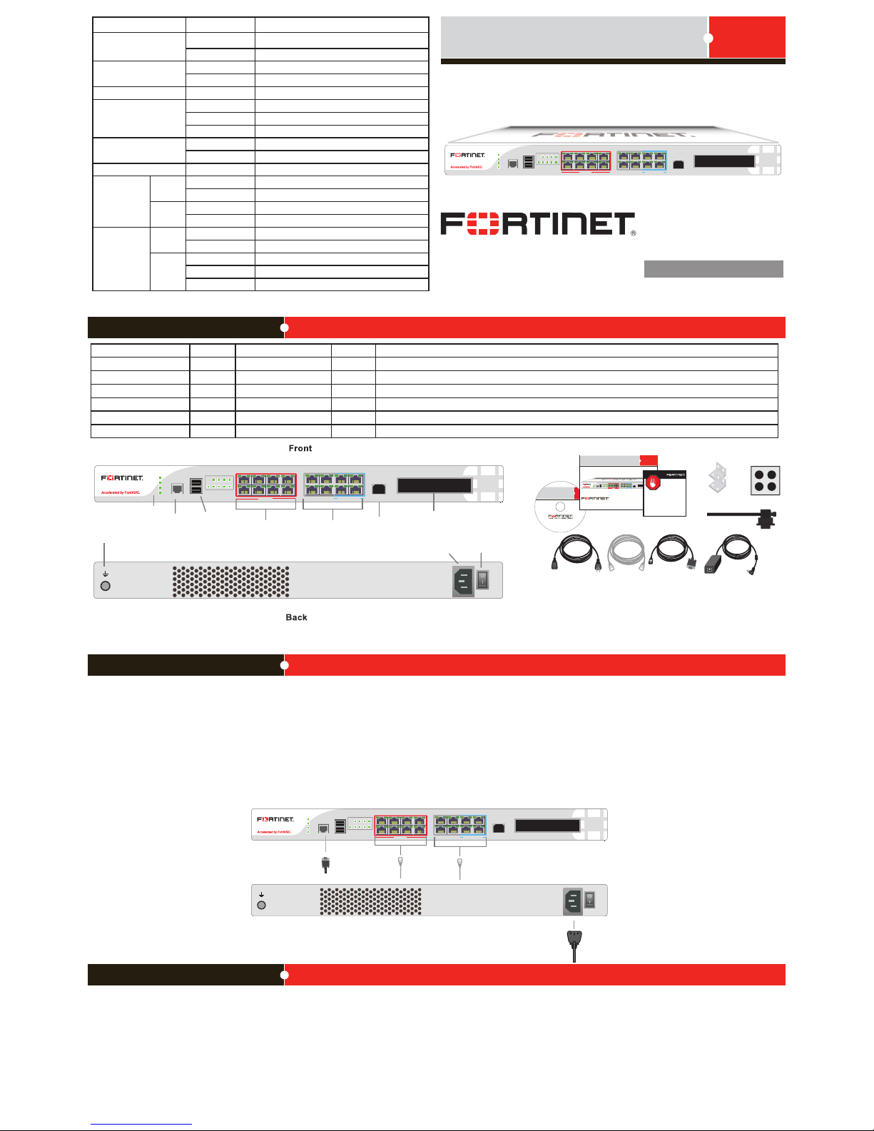
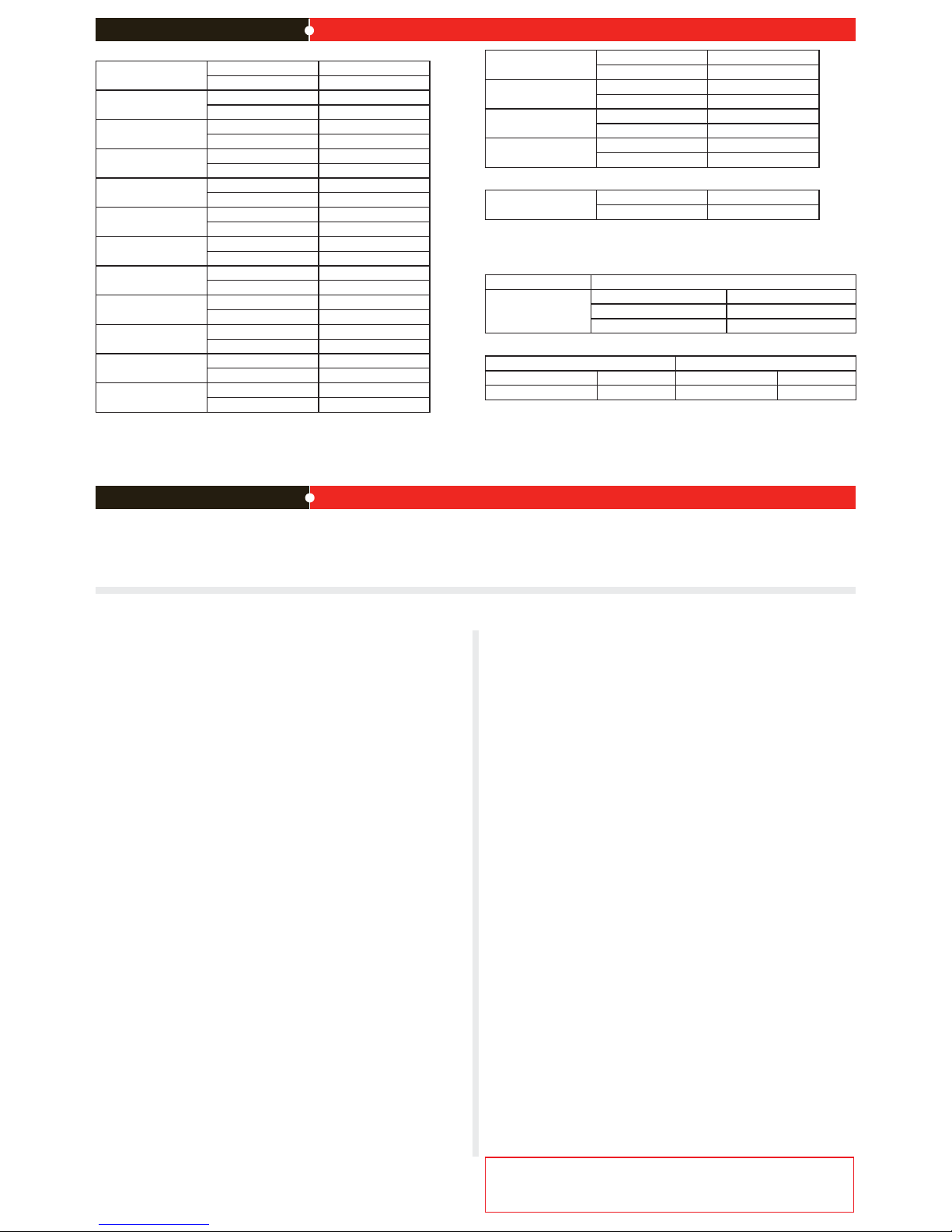
Connecting
POWER
STATUS
HA
ALARM
FortiGate 200B-POE
USBCONSOLE
FortiASIC NP2 Powered
FSM
1 / 2 3 / 4 5 / 6 7 / 8 9 / 10 11 / 12 13 / 14 15 / 16
123 567
8
READY 4
POE PORTS
USB
Console
port
USB
ports
POE ports
FSM
module slot
LEDs
Ports 9 to 16
USB port
(currently not
in use)
AC LINE
100-240V AC
60-50Hz 5-4A
Ground Power
button
AC power
connection
POWER
STATUS
HA
ALARM
FortiGate 200B-POE
USBCONSOLE
FortiASIC NP2 Powered
FSM
1 / 2 3 / 4 5 / 6 7 / 8 9 / 10 11 / 12 13 / 14 15 / 16
123 567
8
READY 4
POE PORTS
USB
RJ-45 to DB-9 cable
connects to serial
port on management
computer
Straight-through Ethernet
cable connects to hub or
switch on the network
Power cable connects to
power supply
AC LINE
100-240V AC
60-50Hz 5-4A
Ethernet cable or
POE
Straigh t-through
Etherne t cable
AC Powe r Cable
RJ-45 t o
DB-9 Se rial Cable
FortiGate-30B
Tools and Documenation
Copyright 2010 Forti net Incorpo rated. All ri ghts reserve d.
Trademarks
QuickStart Guide
Cable Tie
Power S upply (12V)
Rack-Mo unt
Bracket s
4 Rubbe r feet
POWER
STATUS
HA
ALARM
FortiGate 200B-POE
USBCONSOLE
FortiASIC NP2 Powered
FSM
1 / 2 3 / 4 5 / 6 7 / 8 9 / 10 11 / 12 13 / 14 15 / 16
123567
8
READY 4
POE PORTS
USB
REGISTER
Interface Type Speed Protocol Description
Console RJ-45 Ethernet Connection to the management computer. Provides access to the command line interface (CLI).
Ports 1 to 8 RJ-45 10/100 Base-T Ethernet POE source capable ports. Supports up to 15W POE devices.
Ports 9 to 12 RJ-45 10/100/1000 Base-T Ethernet Non-accelerated ports.
Ports 13 to 16 RJ-45 10/100/1000 Base-T Ethernet ASIC accelerated ports.
USB USB USB Two USB 2.0 ports for rmware backup and installation. One USB 2.0 Client port for management.
FSM FSM Fortinet Storage Module. One SATA hard disk drive slot supports 2.5 inch solid state drives.
Package Contents
FortiGate-200B-POE
01-413-117374-20100120
QuickStart Guide
Conguration Tools
Ensure the FortiGate unit is placed on a stable surface. Connect the following to the FortiGate unit:
• Connect the RJ-45 to DB-9 serial cable into the Console port on the unit. Insert the other end into the management computer.
• Insert an ethernet cable into Port 1-8. Insert the other end into a FortiWi-50B.
• Insert the ethernet cable into Port 9 to 16. Insert the other end to the router connected to the Internet, or to the modem.
• Connect the AC power cable to the power supply on the back of the unit.
• Connect the power cord to a surge protected power bar or power supply.
Note: The AC power supply supports 100-240VAC, 60-50 Hz, 5-4 Amp.
Web Cong
Web Cong is an easy to use management tool. Use it to congure the administrator password, the interface and default gateway addresses, and the DNS server addresses, add
devices for log collection and congure reports.
Requirements:
• An Ethernet connection between the Fortinet unit and management computer.
• A web browser such as FireFox or Internet Explorer on the management computer.
Command Line Interface (CLI)
The CLI is a full-featured management tool. Use it to congure the administrator password,
the interface addresses, the default gateway address, and the DNS server addresses. To congure advanced settings, see the Tools and Documentation CD-ROM.
Requirements:
• The RJ-45 to DB-9 serial connection between the Fortinet unit and the
management computer.
• A terminal emulation application (HyperTerminal for Windows) on the management computer.
LED State Description
Power
Green The unit is on.
Off The unit is off.
Status
Green ashing The unit is starting up.
Green The unit is running normally.
HA Green The unit is being used in an HA cluster.
Alarm
Red A critical error has occurred.
Amber A minor error has occurred.
Off No errors detected.
POE
Green POE is in use at that port.
Off POE is not in use at that port.
Ready Green Indicates that POE is available.
Ports 1 to 8
Link/
Activity
Green Port is online.
Flashing Port is sending or receiving data.
Speed Off Connected at 10 Mbps.
Amber Connected at 100 Mbps.
Ports 9 to 16
Link/
Activity
Green Port is online.
Flashing Port is sending or receiving data.
Speed Green Connected at 1000Mbps.
Amber Connected at 100 Mbps.
Off Connected at 10 Mbps.
Page 2
Visit these links for more information and documentation for your Fortinet product.
• Technical Documentation - http://docs.fortinet.com
• Knowledge Center - http://kb.fortinet.com
• Technical Support - http://support.fortinet.com
• Training Services - http://campus.training.fortinet.com
Collecting Information
Conguring
NAT/Route Mode
Port 1 IP: ____.____.____.____
Netmask: ____.____.____.____
Port 2 IP: ____.____.____.____
Netmask: ____.____.____.____
Port 3 IP: ____.____.____.____
Netmask: ____.____.____.____
Port 4 IP: ____.____.____.____
Netmask: ____.____.____.____
Port 5 IP: ____.____.____.____
Netmask: ____.____.____.____
Port 6 IP: ____.____.____.____
Netmask: ____.____.____.____
Port 7 IP: ____.____.____.____
Netmask: ____.____.____.____
Port 8 IP: ____.____.____.____
Netmask: ____.____.____.____
Port 9 IP: ____.____.____.____
Netmask: ____.____.____.____
Port 10 IP: ____.____.____.____
Netmask: ____.____.____.____
Port 11 IP: ____.____.____.____
Netmask: ____.____.____.____
Port 12 IP: ____.____.____.____
Netmask: ____.____.____.____
The internal interface IP address and netmask must be valid for the internal network. A default gateway is required for the FortiGate unit to route connections to the Internet.
Port 13 IP: ____.____.____.____
Netmask: ____.____.____.____
Port 14 IP: ____.____.____.____
Netmask: ____.____.____.____
Port 15 IP: ____.____.____.____
Netmask: ____.____.____.____
Port 16 IP: ____.____.____.____
Netmask: ____.____.____.____
Transparent mode
Management IP: IP: ____.____.____.____
Netmask: ____.____.____.____
The management IP address and netmask must be valid for the network from which you will
manage the FortiGate unit.
General settings
Administrator password:
Network Settings: Default Gateway: ____.____.____.____
Primary DNS Server: ____.____.____.____
Secondary DNS Server: ____.____.____.____
Factory default settings
NAT/Route mode Administrative account settings
Switch 192.168.1.99 User name admin
Port 9 192.168.100.99 Password (none)
To reset the FortiGate unit to the factory defaults, in the CLI type the command
execute factory reset
Web Cong
1. Connect the Fortinet unit’s internal interface to a management computer Ethernet
interface. Use a cross-over Ethernet cable to connect the devices directly. Use straightthrough Ethernet cables to connect the devices through a hub or switch.
2. Congure the management computer to be on the same subnet as the internal interface
of the Fortinet unit. To do this, change the IP address of the management computer to
192.168.1.2 and the netmask to 255.255.255.0.
3. To access the Fortinet web-based manager, start Internet Explorer and browse to
https://192.168.1.99 (remember to include the “s” in https://).
4. Type admin in the Name eld and leave the password eld blank. Click Login.
NAT/Route mode
To change the administrator password
1. Go to System > Admin > Administrators.
2. Select Change Password for the admin administrator and enter a new password.
To congure interfaces
1. Go to System > Network > Interface.
2. Select the edit icon for each interface to congure.
3. Set the addressing mode for the interface. (See the online help for information.)
• For manual addressing, enter the IP address and netmask for the interface.
• For DHCP addressing, select DHCP and any required settings.
• For PPPoE addressing, select PPPoE, and enter the username and password and
any other required settings.
To congure the Primary and Secondary DNS server IP addresses
1. Go to System > Network > Options, enter the Primary and Secondary DNS IP addresses that you recorded above and select Apply.
To congure a Default Gateway
1. Go to Router > Static and select Edit icon for the static route.
2. Set Gateway to the Default Gateway IP address you recorded above and select OK.
Transparent mode
To switch from NAT/route mode to transparent mode
1. Go to System > Cong > Operation Mode and select Transparent.
2. Set the Management IP/Netmask to 192.168.1.99/24.
3. Set a default Gateway and select Apply.
To change the administrator password
1. Go to System > Admin > Administrators.
2. Select Change Password for the admin administrator and enter a new password.
To change the management interface
1. Go to System > Cong > Operation Mode.
2. Enter the Management IP address and netmask that you recorded above and select
Apply.
To congure the Primary and Secondary DNS server IP addresses
1. Go to System > Network > Options, enter the Primary and Secondary DNS IP addresses that you recorded above and select Apply.
Command Line Interface
1. Use the RJ-45 to DB9 serial cable to connect the Fortinet unit’s Console port to the
management computer serial port.
2. Start a terminal emulation program (HyperTerminal) on the management computer. Use
these settings:
3. Baud Rate (bps) 9600, Data bits 8, Parity None, Stop bits 1, and Flow Control None.
4. At the Login: prompt, type admin and press Enter twice (no password required).
NAT/Route mode
1. Congure the Fortinet unit’s internal interface.
cong system interface
edit internal
set ip <intf_ip>/<netmask_ip>
end
2. Repeat to congure each interface, for example, to congure the Port 1 interface.
cong system interface
edit port1
...
3. Congure the primary and secondary DNS server IP addresses.
cong system dns
set primary <dns-server_ip>
set secondary <dns-server_ip>
end
4. Congure the default gateway.
cong router static
edit 1
set gateway <gateway_ip>
end
Transparent Mode
1. Change from NAT/Route mode to Transparent mode and congure the Management IP
address.
cong system settings
set opmode transparent
set manageip <mng_ip>/<netmask>
set gateway <gateway_ip>
end
2. Congure the DNS server IP address.
cong system dns
set primary <dns-server_ip>
set secondary <dns-server_ip>
end
NAT/Route mode
You would typically use NAT/Route mode when the Fortinet unit is deployed as a gateway
between private and public networks. In its default NAT/Route mode conguration, the unit
functions as a rewall. Firewall policies control communications through the Fortinet unit.
Transparent mode
You would typically use the Fortinet unit in Transparent mode on a private network behind
an existing rewall or behind a router. In its default Transparent mode conguration, the unit
functions as a rewall.
 Loading...