

Page 1

FortiGate 100A
Administration Guide
INTERNAL
PWR STATUS
A
WAN 1 WAN 2
DMZ 1
DMZ 2
LINK 100 LINK 100 LINK 100 LINK 100 LINK 100 LINK 100 LINK 100 LINK 100
4321
FortiGate-100A Administration Guide
Version 2.80 MR7
3 December 2004
01-28007-0068-20041203
Page 2

© Copyright 2004 Fortinet Inc. All rights reserved.
No part of this publication including text, examples, diagrams or illustrations may be reproduced,
transmitted, or translated in any form or by any means, electronic, mechanical, manual, optical or
otherwise, for any purpose, without prior written permission of Fortinet Inc.
FortiGate-100A Administration Guide
Version 2.80 MR7
3 December 2004
01-28007-0068-20041203
Trademarks
Products mentioned in this document are trademarks or registered trademarks of their respective holders.
Regulatory Compliance
FCC Class A Part 15 CSA/CUS
CAUTION: RISK OF EXPLOSION IF BATTERY IS REPLACED BY AN INCORRECT TYPE.
DISPOSE OF USED BATTERIES ACCORDING TO THE INSTRUCTIONS.
For technical support, please visit http://www.fortinet.com.
Send information about errors or omissions in this document or any Fortinet technical documentation to
techdoc@fortinet.com.
Page 3

Table of Contents
Introduction.......................................................................................................... 13
About FortiGate Antivirus Firewalls................................................................................... 13
Antivirus protection ....................................................................................................... 14
Web content filtering ..................................................................................................... 14
Spam filtering ................................................................................................................ 15
Firewall.......................................................................................................................... 15
VLANs and virtual domains........................................................................................... 16
Intrusion Prevention System (IPS)................................................................................ 17
VPN............................................................................................................................... 17
High availability ............................................................................................................. 18
Secure installation, configuration, and management .................................................... 18
Document conventions ..................................................................................................... 19
FortiGate documentation .................................................................................................. 21
Fortinet Knowledge Center ........................................................................................... 21
Comments on Fortinet technical documentation........................................................... 21
Related documentation ..................................................................................................... 22
FortiManager documentation ........................................................................................ 22
FortiClient documentation ............................................................................................. 22
FortiMail documentation................................................................................................ 22
FortiLog documentation ................................................................................................ 23
Customer service and technical support........................................................................... 23
Contents
System status....................................................................................................... 25
Console access................................................................................................................. 25
Status................................................................................................................................ 26
Viewing system status .................................................................................................. 26
Changing unit information ............................................................................................. 29
Session list........................................................................................................................ 32
Changing the FortiGate firmware...................................................................................... 33
Upgrading to a new firmware version ........................................................................... 33
Reverting to a previous firmware version...................................................................... 35
Installing firmware images from a system reboot using the CLI ................................... 38
Testing a new firmware image before installing it ......................................................... 41
Installing and using a backup firmware image .............................................................. 43
System network ................................................................................................... 47
Interface............................................................................................................................ 47
Interface settings........................................................................................................... 48
Configuring interfaces ................................................................................................... 53
Zone.................................................................................................................................. 58
Zone settings ................................................................................................................ 58
FortiGate-100A Administration Guide 01-28007-0068-20041203 3
Page 4

Contents
Management..................................................................................................................... 59
DNS .................................................................................................................................. 61
Routing table (Transparent Mode).................................................................................... 62
Routing table list ........................................................................................................... 62
Transparent mode route settings .................................................................................. 62
VLAN overview ................................................................................................................. 63
FortiGate units and VLANs ........................................................................................... 64
VLANs in NAT/Route mode .............................................................................................. 64
Rules for VLAN IDs....................................................................................................... 64
Rules for VLAN IP addresses ....................................................................................... 64
Adding VLAN subinterfaces .......................................................................................... 65
VLANs in Transparent mode............................................................................................. 66
Rules for VLAN IDs....................................................................................................... 68
Transparent mode virtual domains and VLANs ............................................................ 68
Transparent mode VLAN list......................................................................................... 69
Transparent mode VLAN settings................................................................................. 69
FortiGate IPv6 support...................................................................................................... 71
System DHCP ....................................................................................................... 73
Service.............................................................................................................................. 73
DHCP service settings .................................................................................................. 74
Server ............................................................................................................................... 75
DHCP server settings ................................................................................................... 76
Exclude range................................................................................................................... 77
DHCP exclude range settings....................................................................................... 78
IP/MAC binding................................................................................................................. 78
DHCP IP/MAC binding settings .................................................................................... 79
Dynamic IP........................................................................................................................ 79
System config ...................................................................................................... 81
System time ...................................................................................................................... 81
Options.............................................................................................................................. 82
HA..................................................................................................................................... 84
HA configuration ........................................................................................................... 85
Configuring an HA cluster ............................................................................................. 90
Managing an HA cluster................................................................................................ 94
SNMP................................................................................................................................ 97
Configuring SNMP ........................................................................................................ 98
SNMP community ......................................................................................................... 99
FortiGate MIBs............................................................................................................ 101
FortiGate traps ............................................................................................................ 102
Fortinet MIB fields ....................................................................................................... 103
4 01-28007-0068-20041203 Fortinet Inc.
Page 5

Replacement messages ................................................................................................. 106
Replacement messages list ........................................................................................ 106
Changing replacement messages .............................................................................. 107
FortiManager................................................................................................................... 108
System administration ...................................................................................... 109
Administrators................................................................................................................. 109
Administrators list........................................................................................................ 110
Administrators options ................................................................................................ 110
Access profiles................................................................................................................ 111
Access profile list ........................................................................................................ 112
Access profile options ................................................................................................. 112
System maintenance ......................................................................................... 115
Backup and restore......................................................................................................... 115
Backing up and Restoring........................................................................................... 116
Update center ................................................................................................................. 118
Updating antivirus and attack definitions .................................................................... 120
Enabling push updates ............................................................................................... 123
Support ........................................................................................................................... 125
Sending a bug report .................................................................................................. 126
Registering a FortiGate unit ........................................................................................ 127
Shutdown........................................................................................................................ 129
Contents
System virtual domain....................................................................................... 131
Virtual domain properties................................................................................................ 132
Exclusive virtual domain properties ............................................................................ 132
Shared configuration settings ..................................................................................... 133
Administration and management ................................................................................ 134
Virtual domains ............................................................................................................... 134
Adding a virtual domain .............................................................................................. 135
Selecting a virtual domain........................................................................................... 135
Selecting a management virtual domain..................................................................... 135
Configuring virtual domains ............................................................................................ 136
Adding interfaces, VLAN subinterfaces, and zones to a virtual domain ..................... 136
Configuring routing for a virtual domain ...................................................................... 138
Configuring firewall policies for a virtual domain......................................................... 138
Configuring IPSec VPN for a virtual domain ............................................................... 140
Router ................................................................................................................. 141
Static............................................................................................................................... 141
Static route list ............................................................................................................ 143
Static route options ..................................................................................................... 144
FortiGate-100A Administration Guide 01-28007-0068-20041203 5
Page 6

Contents
Policy .............................................................................................................................. 145
Policy route list............................................................................................................ 145
Policy route options..................................................................................................... 146
RIP.................................................................................................................................. 146
General ....................................................................................................................... 147
Networks list................................................................................................................ 148
Networks options ........................................................................................................ 149
Interface list................................................................................................................. 149
Interface options ......................................................................................................... 150
Distribute list ............................................................................................................... 151
Distribute list options................................................................................................... 152
Offset list ..................................................................................................................... 153
Offset list options ........................................................................................................ 153
Router objects................................................................................................................. 154
Access list ................................................................................................................... 154
New access list ........................................................................................................... 154
New access list entry .................................................................................................. 155
Prefix list ..................................................................................................................... 155
New Prefix list ............................................................................................................. 156
New prefix list entry..................................................................................................... 157
Route-map list............................................................................................................. 157
New Route-map .......................................................................................................... 158
Route-map list entry.................................................................................................... 159
Key chain list............................................................................................................... 160
New key chain............................................................................................................. 160
Key chain list entry...................................................................................................... 161
Monitor............................................................................................................................ 162
Routing monitor list ..................................................................................................... 162
CLI configuration............................................................................................................. 163
get router info ospf ...................................................................................................... 163
get router info protocols .............................................................................................. 163
get router info rip......................................................................................................... 164
config router ospf ....................................................................................................... 164
config router static6..................................................................................................... 187
Firewall................................................................................................................ 189
Policy .............................................................................................................................. 190
How policy matching works......................................................................................... 190
Policy list ..................................................................................................................... 190
Policy options.............................................................................................................. 191
Advanced policy options ............................................................................................. 194
Configuring firewall policies ........................................................................................ 196
Policy CLI configuration .............................................................................................. 197
6 01-28007-0068-20041203 Fortinet Inc.
Page 7

Address........................................................................................................................... 198
Address list ................................................................................................................. 199
Address options .......................................................................................................... 199
Configuring addresses ................................................................................................ 200
Address group list ....................................................................................................... 201
Address group options ................................................................................................ 201
Configuring address groups........................................................................................ 202
Service............................................................................................................................ 203
Predefined service list................................................................................................. 203
Custom service list...................................................................................................... 206
Custom service options............................................................................................... 207
Configuring custom services....................................................................................... 208
Service group list ........................................................................................................ 209
Service group options ................................................................................................. 209
Configuring service groups ......................................................................................... 210
Schedule......................................................................................................................... 211
One-time schedule list ................................................................................................ 211
One-time schedule options ......................................................................................... 212
Configuring one-time schedules ................................................................................. 212
Recurring schedule list................................................................................................ 213
Recurring schedule options ........................................................................................ 213
Configuring recurring schedules ................................................................................. 214
Virtual IP ......................................................................................................................... 214
Virtual IP list ................................................................................................................ 215
Virtual IP options......................................................................................................... 215
Configuring virtual IPs................................................................................................. 216
IP pool............................................................................................................................. 219
IP pool list ................................................................................................................... 220
IP pool options ............................................................................................................ 220
Configuring IP pools.................................................................................................... 220
IP Pools for firewall policies that use fixed ports ......................................................... 221
IP pools and dynamic NAT ......................................................................................... 221
Protection profile............................................................................................................. 222
Protection profile list.................................................................................................... 222
Default protection profiles ........................................................................................... 223
Protection profile options ............................................................................................ 223
Configuring protection profiles .................................................................................... 228
Profile CLI configuration.............................................................................................. 229
Contents
Users and authentication .................................................................................. 233
Setting authentication timeout......................................................................................... 234
Local ............................................................................................................................... 234
Local user list .............................................................................................................. 234
Local user options....................................................................................................... 234
FortiGate-100A Administration Guide 01-28007-0068-20041203 7
Page 8

Contents
RADIUS .......................................................................................................................... 235
RADIUS server list ...................................................................................................... 235
RADIUS server options............................................................................................... 236
LDAP............................................................................................................................... 236
LDAP server list .......................................................................................................... 237
LDAP server options ................................................................................................... 237
User group ...................................................................................................................... 239
User group list............................................................................................................. 239
User group options...................................................................................................... 240
CLI configuration............................................................................................................. 241
peer............................................................................................................................. 241
peergrp........................................................................................................................ 242
VPN...................................................................................................................... 245
Phase 1........................................................................................................................... 246
Phase 1 list ................................................................................................................. 246
Phase 1 basic settings ................................................................................................ 247
Phase 1 advanced settings......................................................................................... 249
Phase 2........................................................................................................................... 250
Phase 2 list ................................................................................................................. 251
Phase 2 basic settings ................................................................................................ 251
Phase 2 advanced options.......................................................................................... 252
Manual key...................................................................................................................... 253
Manual key list ............................................................................................................ 254
Manual key options ..................................................................................................... 255
Concentrator ................................................................................................................... 256
Concentrator list.......................................................................................................... 256
Concentrator options................................................................................................... 257
Ping Generator................................................................................................................ 257
Ping generator options................................................................................................ 258
Monitor............................................................................................................................ 258
Dialup monitor............................................................................................................. 259
Static IP and dynamic DNS monitor............................................................................ 259
PPTP............................................................................................................................... 260
PPTP range ................................................................................................................ 260
L2TP .............................................................................................................................. 261
L2TP range ................................................................................................................. 261
Certificates...................................................................................................................... 262
Local certificate list...................................................................................................... 262
Certificate request....................................................................................................... 263
Importing signed certificates ...................................................................................... 264
CA certificate list ......................................................................................................... 265
Importing CA certificates............................................................................................. 265
8 01-28007-0068-20041203 Fortinet Inc.
Page 9

VPN configuration procedures........................................................................................ 266
IPSec configuration procedures.................................................................................. 266
PPTP configuration procedures .................................................................................. 268
L2TP configuration procedures................................................................................... 268
CLI configuration............................................................................................................. 269
ipsec phase1............................................................................................................... 269
ipsec phase2............................................................................................................... 271
ipsec vip ...................................................................................................................... 272
IPS ....................................................................................................................... 277
Signature......................................................................................................................... 278
Predefined................................................................................................................... 278
Custom........................................................................................................................ 282
Anomaly.......................................................................................................................... 284
Anomaly CLI configuration.......................................................................................... 287
Configuring IPS logging and alert email.......................................................................... 288
Default fail open setting .................................................................................................. 288
Antivirus ............................................................................................................. 289
Contents
File block......................................................................................................................... 290
File block list ............................................................................................................... 291
Configuring the file block list ....................................................................................... 292
Quarantine ...................................................................................................................... 292
Quarantined files list ................................................................................................... 292
Quarantined files list options....................................................................................... 293
AutoSubmit list ............................................................................................................ 294
AutoSubmit list options ............................................................................................... 294
Configuring the AutoSubmit list................................................................................... 294
Config.......................................................................................................................... 295
Config.............................................................................................................................. 296
Virus list ...................................................................................................................... 296
Config.......................................................................................................................... 296
Grayware .................................................................................................................... 297
Grayware options........................................................................................................ 297
CLI configuration............................................................................................................. 299
config antivirus heuristic.............................................................................................. 299
config antivirus quarantine .......................................................................................... 300
config antivirus service http......................................................................................... 300
config antivirus service ftp........................................................................................... 302
config antivirus service pop3....................................................................................... 304
config antivirus service imap....................................................................................... 305
config antivirus service smtp....................................................................................... 307
FortiGate-100A Administration Guide 01-28007-0068-20041203 9
Page 10

Contents
Web filter............................................................................................................. 309
Content block.................................................................................................................. 311
Web content block list ................................................................................................. 311
Web content block options.......................................................................................... 311
Configuring the web content block list ........................................................................ 312
URL block ....................................................................................................................... 312
Web URL block list...................................................................................................... 313
Web URL block options .............................................................................................. 313
Configuring the web URL block list ............................................................................. 314
Web pattern block list.................................................................................................. 314
Web pattern block options .......................................................................................... 315
Configuring web pattern block .................................................................................... 315
URL exempt.................................................................................................................... 315
URL exempt list........................................................................................................... 316
URL exempt list options .............................................................................................. 316
Configuring URL exempt............................................................................................. 316
Category block................................................................................................................ 317
FortiGuard managed web filtering service .................................................................. 317
Category block configuration options.......................................................................... 318
Configuring web category block.................................................................................. 319
Category block reports................................................................................................ 319
Category block reports options ................................................................................... 320
Generating a category block report............................................................................. 320
Category block CLI configuration................................................................................ 320
Script filter....................................................................................................................... 321
Web script filter options............................................................................................... 322
Spam filter .......................................................................................................... 323
FortiShield....................................................................................................................... 325
FortiShield options ...................................................................................................... 326
Configuring the FortiShield cache............................................................................... 326
IP address....................................................................................................................... 327
IP address list ............................................................................................................. 327
IP address options ...................................................................................................... 327
Configuring the IP address list .................................................................................... 328
RBL & ORDBL ................................................................................................................ 328
RBL & ORDBL list....................................................................................................... 329
RBL & ORDBL options................................................................................................ 329
Configuring the RBL & ORDBL list ............................................................................. 329
Email address ................................................................................................................. 330
Email address list........................................................................................................ 330
Email address options................................................................................................. 330
Configuring the email address list............................................................................... 331
10 01-28007-0068-20041203 Fortinet Inc.
Page 11

MIME headers................................................................................................................. 331
MIME headers list ....................................................................................................... 332
MIME headers options ................................................................................................ 332
Configuring the MIME headers list.............................................................................. 333
Banned word................................................................................................................... 333
Banned word list ......................................................................................................... 334
Banned word options .................................................................................................. 334
Configuring the banned word list ................................................................................ 335
Using Perl regular expressions....................................................................................... 335
Log & Report ...................................................................................................... 339
Log config ....................................................................................................................... 340
Log Setting options ..................................................................................................... 340
Alert E-mail options..................................................................................................... 344
Log filter options.......................................................................................................... 345
Configuring log filters .................................................................................................. 348
Enabling traffic logging................................................................................................ 348
Log access...................................................................................................................... 349
Viewing log messages ................................................................................................ 349
Searching log messages............................................................................................. 351
CLI configuration............................................................................................................. 352
fortilog setting.............................................................................................................. 352
syslogd setting ............................................................................................................ 354
Contents
FortiGuard categories ....................................................................................... 357
Glossary ............................................................................................................. 363
Index .................................................................................................................... 367
FortiGate-100A Administration Guide 01-28007-0068-20041203 11
Page 12

Contents
12 01-28007-0068-20041203 Fortinet Inc.
Page 13

FortiGate-100A Administration Guide Version 2.80 MR7
Introduction
FortiGate Antivirus Firewalls support network-based deployment of application-level
services, including antivirus protection and full-scan content filtering. FortiGate
Antivirus Firewalls improve network security, reduce network misuse and abuse, and
help you use communications resources more efficiently without compromising the
performance of your network. FortiGate Antivirus Firewalls are ICSA-certified for
firewall, IPSec, and antivirus services.
This chapter introduces you to FortiGate Antivirus Firewalls and the following topics:
• About FortiGate Antivirus Firewalls
• Document conventions
• FortiGate documentation
• Related documentation
• Customer service and technical support
About FortiGate Antivirus Firewalls
The FortiGate Antivirus Firewall is a dedicated easily managed security device that
delivers a full suite of capabilities that include:
• application-level services such as virus protection and content filtering,
• network-level services such as firewall, intrusion detection, VPN, and traffic
shaping.
The FortiGate Antivirus Firewall uses Fortinet’s Accelerated Behavior and Content
Analysis System (ABACAS™) technology, which leverages breakthroughs in chip
design, networking, security, and content analysis. The unique ASIC-based
architecture analyzes content and behavior in real-time, enabling key applications to
be deployed right at the network edge, where they are most effective at protecting
your networks. The FortiGate series complements existing solutions, such as hostbased antivirus protection, and enables new applications and services while greatly
lowering costs for equipment, administration, and maintenance.
The FortiGate-100A model is an easy-todeploy and easy-to-administer solution that
delivers exceptional value and performance
for small office, home office, and branch
office applications. The FortiGate
installation wizard guides users through a simple process that enables most
installations to be up and running in minutes.
WAN 1 WAN 2
PWR STATUS
A
DMZ 1
LINK 100 LINK 100 LINK 100 LINK 100 LINK 100 LINK 100 LINK 100 LINK 100
INTERNAL
DMZ 2
4321
FortiGate-100A Administration Guide 01-28007-0068-20041203 13
Page 14

Antivirus protection Introduction
The FortiGate-100A also supports advanced features such as multiple WAN and DMZ
interfaces, 802.1Q VLAN, virtual domains, high availability (HA), and the RIP and
OSPF routing protocols.
Antivirus protection
FortiGate ICSA-certified antivirus protection scans web (HTTP), file transfer (FTP),
and email (SMTP, POP3, and IMAP) content as it passes through the FortiGate unit.
FortiGate antivirus protection uses pattern matching and heuristics to find viruses. If a
virus is found, antivirus protection removes the file containing the virus from the
content stream and forwards a replacement message to the intended recipient.
For extra protection, you can configure antivirus protection to block specified file types
from passing through the FortiGate unit. You can use the feature to stop files that
might contain new viruses.
FortiGate antivirus protection can also identify and remove known grayware
programs. Grayware programs are usually unsolicited commercial software programs
that get installed on PCs, often without the user’s consent or knowledge. Grayware
programs are generally considered an annoyance, but these programs can cause
system performance problems or be used for malicious means.
If the FortiGate unit contains a hard disk, infected or blocked files and grayware files
can be quarantined. The FortiGate administrator can download quarantined files so
that they can be virus scanned, cleaned, and forwarded to the intended recipient. You
can also configure the FortiGate unit to automatically delete quarantined files after a
specified time.
The FortiGate unit can send email alerts to system administrators when it detects and
removes a virus from a content stream. The web and email content can be in normal
network traffic or encrypted IPSec VPN traffic.
ICSA Labs has certified that FortiGate Antivirus Firewalls:
• detect 100% of the viruses listed in the current In The Wild List (www.wildlist.org),
• detect viruses in compressed files using the PKZip format,
• detect viruses in email that has been encoded using uuencode format,
• detect viruses in email that has been encoded using MIME encoding,
• log all actions taken while scanning.
Web content filtering
FortiGate web content filtering can scan all HTTP content protocol streams for URLs,
URL patterns, and web page content. If there is a match between a URL on the URL
block list, or a web page contains a word or phrase that is in the content block list, the
FortiGate unit blocks the web page. The blocked web page is replaced with a
message that you can edit using the FortiGate web-based manager.
FortiGate web content filtering also supports FortiGuard web category blocking. Using
web category blocking you can restrict or allow access to web pages based on
content ratings of web pages.
You can configure URL blocking to block all or some of the pages on a web site. Using
this feature, you can deny access to parts of a web site without denying access to it
completely.
14 01-28007-0068-20041203 Fortinet Inc.
Page 15

Introduction Spam filtering
To prevent unintentionally blocking legitimate web pages, you can add URLs to an
exempt list that overrides the URL blocking and content blocking lists. The exempt list
also exempts web traffic this address from virus scanning.
Web content filtering also includes a script filter feature that can block unsecure web
content such as Java applets, cookies, and ActiveX.
Spam filtering
FortiGate spam filtering can scan all POP3, SMTP, and IMAP email content for spam.
You can configure spam filtering to filter mail according to IP address, email address,
mime headers, and content. Mail messages can be identified as spam or clear.
You can also add the names of known Real-time Blackhole List (RBL) and Open
Relay Database List (ORDBL) servers. These services contain lists of known spam
sources.
If an email message is found to be spam, the FortiGate adds an email tag to the
subject line of the email. The recipient can use the mail client software to filter
messages based on the email tag. Spam filtering can also be configured to delete
SMTP email messages identified as spam.
Firewall
The FortiGate ICSA-certified firewall protects your computer networks from Internet
threats. ICSA has granted FortiGate firewalls version 4.0 firewall certification,
providing assurance that FortiGate firewalls successfully screen and secure corporate
networks against a range of threats from public or other untrusted networks.
After basic installation of the FortiGate unit, the firewall allows users on the protected
network to access the Internet while blocking Internet access to internal networks.
You can configure the firewall to put controls on access to the Internet from the
protected networks and to allow controlled access to internal networks.
FortiGate policies include a range of options that:
• control all incoming and outgoing network traffic,
• control encrypted VPN traffic,
• apply antivirus protection and web content filtering,
• block or allow access for all policy options,
• control when individual policies are in effect,
• accept or deny traffic to and from individual addresses,
• control standard and user defined network services individually or in groups,
• require users to authenticate before gaining access,
• include traffic shaping to set access priorities and guarantee or limit bandwidth for
each policy,
• include logging to track connections for individual policies,
• include Network Address Translation (NAT) mode and Route mode policies,
• include mixed NAT and Route mode policies.
The FortiGate firewall can operate in NAT/Route mode or Transparent mode.
FortiGate-100A Administration Guide 01-28007-0068-20041203 15
Page 16

VLANs and virtual domains Introduction
NAT/Route mode
In NAT/Route mode, the FortiGate unit is a Layer 3 device. This means that each of its
interfaces is associated with a different IP subnet and that it appears to other devices
as a router. This is how a firewall is normally deployed.
In NAT/Route mode, you can create NAT mode policies and Route mode policies.
• NAT mode policies use network address translation to hide the addresses in a
more secure network from users in a less secure network.
• Route mode policies accept or deny connections between networks without
performing address translation.
Transparent mode
In Transparent mode, the FortiGate unit does not change the Layer 3 topology. This
means that all of its interfaces are on the same IP subnet and that it appears to other
devices as a bridge. Typically, the FortiGate unit is deployed in Transparent mode to
provide antivirus and content filtering behind an existing firewall solution.
Transparent mode provides the same basic firewall protection as NAT mode. The
FortiGate unit passes or blocks the packets it receives according to firewall policies.
The FortiGate unit can be inserted in the network at any point without having to make
changes to your network or its components. However, some advanced firewall
features are available only in NAT/Route mode.
VLANs and virtual domains
Fortigate Antivirus Firewalls support IEEE 802.1Q-compliant virtual LAN (VLAN) tags.
Using VLAN technology, a single FortiGate unit can provide security services to, and
control connections between, multiple security domains according to the VLAN IDs
added to VLAN packets. The FortiGate unit can recognize VLAN IDs and apply
security policies to secure network and IPSec VPN traffic between each security
domain. The FortiGate unit can also apply authentication, content filtering, and
antivirus protection to VLAN-tagged network and VPN traffic.
The FortiGate unit supports VLANs in NAT/Route and Transparent mode. In
NAT/Route mode, you enter VLAN subinterfaces to receive and send VLAN packets.
FortiGate virtual domains provide multiple logical firewalls and routers in a single
FortiGate unit. Using virtual domains, one FortiGate unit can provide exclusive firewall
and routing services to multiple networks so that traffic from each network is
effectively separated from every other network.
You can develop and manage interfaces, VLAN subinterfaces, zones, firewall policies,
routing, and VPN configuration for each virtual domain separately. For these
configuration settings, each virtual domain is functionally similar to a single FortiGate
unit. This separation simplifies configuration because you do not have to manage as
many routes or firewall policies at one time.
16 01-28007-0068-20041203 Fortinet Inc.
Page 17

Introduction Intrusion Prevention System (IPS)
Intrusion Prevention System (IPS)
The FortiGate Intrusion Prevention System (IPS) combines signature and anomaly
based intrusion detection and prevention. The FortiGate unit can record suspicious
traffic in logs, can send alert email to system administrators, and can log, pass, drop,
reset, or clear suspicious packets or sessions. Both the IPS predefined signatures and
the IPS engine are upgradeable through the FortiProtect Distribution Network (FDN).
You can also create custom signatures.
VPN
Using FortiGate virtual private networking (VPN), you can provide a secure
connection between widely separated office networks or securely link telecommuters
or travellers to an office network.
FortiGate VPN features include the following:
• Industry standard and ICSA-certified IPSec VPN, including:
• IPSec VPN in NAT/Route and Transparent mode,
• IPSec, ESP security in tunnel mode,
• DES, 3DES (triple-DES), and AES hardware accelerated encryption,
• HMAC MD5 and HMAC SHA1 authentication and data integrity,
• AutoIKE key based on pre-shared key tunnels,
• IPSec VPN using local or CA certificates,
• Manual Keys tunnels,
• Diffie-Hellman groups 1, 2, and 5,
• Aggressive and Main Mode,
• Replay Detection,
• Perfect Forward Secrecy,
• XAuth authentication,
• Dead peer detection,
• DHCP over IPSec,
• Secure Internet browsing.
• PPTP for easy connectivity with the VPN standard supported by the most popular
operating systems.
• L2TP for easy connectivity with a more secure VPN standard, also supported by
many popular operating systems.
• Firewall policy based control of IPSec VPN traffic.
• IPSec NAT traversal so that remote IPSec VPN gateways or clients behind a NAT
can connect to an IPSec VPN tunnel.
• VPN hub and spoke using a VPN concentrator to allow VPN traffic to pass from
one tunnel to another through the FortiGate unit.
• IPSec Redundancy to create a redundant AutoIKE key IPSec VPN connection to a
remote network.
FortiGate-100A Administration Guide 01-28007-0068-20041203 17
Page 18

High availability Introduction
High availability
Fortinet achieves high availability (HA) using redundant hardware and the FortiGate
Clustering Protocol (FGCP). Each FortiGate unit in an HA cluster enforces the same
overall security policy and shares the same configuration settings. You can add up to
32 FortiGate units to an HA cluster. Each FortiGate unit in an HA cluster must be the
same model and must be running the same FortiOS firmware image.
FortiGate HA supports link redundancy and device redundancy.
FortiGate units can be configured to operate in active-passive (A-P) or active-active
(A-A) HA mode. Active-active and active-passive clusters can run in either NAT/Route
or Transparent mode.
An active-passive (A-P) HA cluster, also referred to as hot standby HA, consists of a
primary FortiGate unit that processes traffic, and one or more subordinate FortiGate
units. The subordinate FortiGate units are connected to the network and to the
primary FortiGate unit but do not process traffic.
Active-active (A-A) HA load balances virus scanning among all the FortiGate units in
the cluster. An active-active HA cluster consists of a primary FortiGate unit that
processes traffic and one or more secondary units that also process traffic. The
primary FortiGate unit uses a load balancing algorithm to distribute virus scanning to
all the FortiGate units in the HA cluster.
Secure installation, configuration, and management
The first time you power on the FortiGate unit, it is already configured with default IP
addresses and security policies. Connect to the web-based manager, set the
operating mode, and use the Setup wizard to customize FortiGate IP addresses for
your network, and the FortiGate unit is ready to protect your network. You can then
use the web-based manager to customize advanced FortiGate features.
Web-based manager
Using HTTP or a secure HTTPS connection from any computer running Internet
Explorer, you can configure and manage the FortiGate unit. The web-based manager
supports multiple languages. You can configure the FortiGate unit for HTTP and
HTTPS administration from any FortiGate interface.
You can use the web-based manager to configure most FortiGate settings. You can
also use the web-based manager to monitor the status of the FortiGate unit.
Configuration changes made using the web-based manager are effective immediately
without resetting the firewall or interrupting service. Once you are satisfied with a
configuration, you can download and save it. The saved configuration can be restored
at any time.
Command line interface
You can access the FortiGate command line interface (CLI) by connecting a
management computer serial port to the FortiGate RS-232 serial console connector.
You can also use Telnet or a secure SSH connection to connect to the CLI from any
network that is connected to the FortiGate unit, including the Internet.
18 01-28007-0068-20041203 Fortinet Inc.
Page 19

Introduction Secure installation, configuration, and management
The CLI supports the same configuration and monitoring functionality as the
web-based manager. In addition, you can use the CLI for advanced configuration
options that are not available from the web-based manager.
This Administration Guide contains information about basic and advanced CLI
commands. For a more complete description about connecting to and using the
FortiGate CLI, see the FortiGate CLI Reference Guide.
Logging and reporting
The FortiGate unit supports logging for various categories of traffic and configuration
changes. You can configure logging to:
• report traffic that connects to the firewall,
• report network services used,
• report traffic that was permitted by firewall policies,
• report traffic that was denied by firewall policies,
• report events such as configuration changes and other management events,
IPSec tunnel negotiation, virus detection, attacks, and web page blocking,
• report attacks detected by the IPS,
• send alert email to system administrators to report virus incidents, intrusions, and
firewall or VPN events or violations.
Logs can be sent to a remote syslog server or a WebTrends NetIQ Security Reporting
Center and Firewall Suite server using the WebTrends enhanced log format. Some
models can also save logs to an optional internal hard drive. If a hard drive is not
installed, you can configure most FortiGate units to log the most recent events and
attacks detected by the IPS to the system memory.
Document conventions
This guide uses the following conventions to describe CLI command syntax.
• Angle brackets < > to indicate variables.
For example:
execute restore config <filename_str>
FortiGate-100A Administration Guide 01-28007-0068-20041203 19
Page 20

Secure installation, configuration, and management Introduction
You enter:
execute restore config myfile.bak
<xxx_str> indicates an ASCII string that does not contain new-lines or carriage
returns.
<xxx_integer> indicates an integer string that is a decimal (base 10) number.
<xxx_octet> indicates a hexadecimal string that uses the digits 0-9 and letters
A-F.
<xxx_ipv4> indicates a dotted decimal IPv4 address.
<xxx_v4mask> indicates a dotted decimal IPv4 netmask.
<xxx_ipv4mask> indicates a dotted decimal IPv4 address followed by a dotted
decimal IPv4 netmask.
<xxx_ipv6> indicates a dotted decimal IPv6 address.
<xxx_v6mask> indicates a dotted decimal IPv6 netmask.
<xxx_ipv6mask> indicates a dotted decimal IPv6 address followed by a dotted
decimal IPv6 netmask.
• Vertical bar and curly brackets {|} to separate alternative, mutually exclusive
required keywords.
For example:
set opmode {nat | transparent}
You can enter set opmode nat or set opmode transparent.
• Square brackets [ ] to indicate that a keyword or variable is optional.
For example:
show system interface [<name_str>]
To show the settings for all interfaces, you can enter show system interface.
To show the settings for the internal interface, you can enter show system
interface internal.
• A space to separate options that can be entered in any combination and must be
separated by spaces.
For example:
set allowaccess {ping https ssh snmp http telnet}
You can enter any of the following:
set allowaccess ping
set allowaccess ping https ssh
set allowaccess https ping ssh
set allowaccess snmp
In most cases to make changes to lists that contain options separated by spaces,
you need to retype the whole list including all the options you want to apply and
excluding all the options you want to remove.
20 01-28007-0068-20041203 Fortinet Inc.
Page 21

Introduction Fortinet Knowledge Center
FortiGate documentation
Information about FortiGate products is available from the following guides:
• FortiGate QuickStart Guide
Provides basic information about connecting and installing a FortiGate unit.
• FortiGate Installation Guide
Describes how to install a FortiGate unit. Includes a hardware reference, default
configuration information, installation procedures, connection procedures, and
basic configuration procedures. Choose the guide for your product model number.
• FortiGate Administration Guide
Provides basic information about how to configure a FortiGate unit, including how
to define FortiGate protection profiles and firewall policies; how to apply intrusion
prevention, antivirus protection, web content filtering, and spam filtering; and how
to configure a VPN.
• FortiGate online help
Provides a context-sensitive and searchable version of the Administration Guide in
HTML format. You can access online help from the web-based manager as you
work.
• FortiGate CLI Reference Guide
Describes how to use the FortiGate CLI and contains a reference to all FortiGate
CLI commands.
• FortiGate Log Message Reference Guide
Describes the structure of FortiGate log messages and provides information about
the log messages that are generated by FortiGate units.
• FortiGate High Availability Guide
Contains in-depth information about the FortiGate high availability feature and the
FortiGate clustering protocol.
• FortiGate IPS Guide
Describes how to configure the FortiGate Intrusion Prevention System settings and
how the FortiGate IPS deals with some common attacks.
• FortiGate VPN Guide
Explains how to configure VPNs using the web-based manager.
Fortinet Knowledge Center
The most recent Fortinet technical documentation is available from the Fortinet
Knowledge Center. The knowledge center contains short how-to articles, FAQs,
technical notes, product and feature guides, and much more. Visit the Fortinet
Knowledge Center at http://kc.forticare.com.
Comments on Fortinet technical documentation
Please send information about any errors or omissions in this document, or any
Fortinet technical documentation, to techdoc@fortinet.com.
FortiGate-100A Administration Guide 01-28007-0068-20041203 21
Page 22

FortiManager documentation Introduction
Related documentation
Additional information about Fortinet products is available from the following related
documentation.
FortiManager documentation
• FortiManager QuickStart Guide
Explains how to install the FortiManager Console, set up the FortiManager Server,
and configure basic settings.
• FortiManager System Administration Guide
Describes how to use the FortiManager System to manage FortiGate devices.
• FortiManager System online help
Provides a searchable version of the Administration Guide in HTML format. You
can access online help from the FortiManager Console as you work.
FortiClient documentation
• FortiClient Host Security User Guide
Describes how to use FortiClient Host Security software to set up a VPN
connection from your computer to remote networks, scan your computer for
viruses, and restrict access to your computer and applications by setting up firewall
policies.
• FortiClient Host Security online help
Provides information and procedures for using and configuring the FortiClient
software.
FortiMail documentation
• FortiMail Administration Guide
Describes how to install, configure, and manage a FortiMail unit in gateway mode
and server mode, including how to configure the unit; create profiles and policies;
configure antispam and antivirus filters; create user accounts; and set up logging
and reporting.
• FortiMail online help
Provides a searchable version of the Administration Guide in HTML format. You
can access online help from the web-based manager as you work.
• FortiMail Web Mail Online Help
Describes how to use the FortiMail web-based email client, including how to send
and receive email; how to add, import, and export addresses; and how to configure
message display preferences.
22 01-28007-0068-20041203 Fortinet Inc.
Page 23

Introduction FortiLog documentation
FortiLog documentation
• FortiLog Administration Guide
Describes how to install and configure a FortiLog unit to collect FortiGate and
FortiMail log files. It also describes how to view FortiGate and FortiMail log files,
generate and view log reports, and use the FortiLog unit as a NAS server.
• FortiLog online help
Provides a searchable version of the Administration Guide in HTML format. You
can access online help from the web-based manager as you work.
Customer service and technical support
For antivirus and attack definition updates, firmware updates, updated product
documentation, technical support information, and other resources, please visit the
Fortinet Technical Support web site at http://support.fortinet.com.
You can also register Fortinet products and service contracts from
http://support.fortinet.com and change your registration information at any time.
Technical support is available through email from any of the following addresses.
Choose the email address for your region:
amer_support@fortinet.com For customers in the United States, Canada, Mexico, Latin
apac_support@fortinet.com For customers in Japan, Korea, China, Hong Kong, Singapore,
eu_support@fortinet.com For customers in the United Kingdom, Scandinavia, Mainland
For information about our priority support hotline (live support), see
http://support.fortinet.com.
When requesting technical support, please provide the following information:
• your name
• your company’s name and location
• your email address
• your telephone number
• your support contract number (if applicable)
• the product name and model number
• the product serial number (if applicable)
America and South America.
Malaysia, all other Asian countries, and Australia.
Europe, Africa, and the Middle East.
• the software or firmware version number
• a detailed description of the problem
FortiGate-100A Administration Guide 01-28007-0068-20041203 23
Page 24

FortiLog documentation Introduction
24 01-28007-0068-20041203 Fortinet Inc.
Page 25

FortiGate-100A Administration Guide Version 2.80 MR7
System status
You can connect to the web-based manager and view the current system status of the
FortiGate unit. The status information that is displayed includes the system status, unit
information, system resources, and session log.
This chapter includes:
• Console access
• Status
• Session list
• Changing the FortiGate firmware
Console access
An alternative to the web-based manager discussed in this manual is text-based
Console Access, using the FortiGate command line interface (CLI). You can get
console access by selecting Console Access button in the upper right corner of the
web-based manager. The management computer must have Java version 1.3 or
higher installed.
For information on how to use the CLI, see the FortiGate CLI Reference Guide.
Figure 1: Console access
FortiGate-100A Administration Guide 01-28007-0068-20041203 25
Page 26

Viewing system status System status
Connect Select Connect to connect to the CLI.
Disconnect Select Disconnect to disconnect from the CLI.
Clear screen Select Clear screen to start a new page.
Status
View the system status page, also known as the system dashboard, for a snap shot of
the current operating status of the FortiGate unit. All FortiGate administrators with
read access to system configuration can view system status information.
On HA clusters, the Status page shows the status of the primary unit. To view status
information for all members of the cluster, go to System > Config > HA and select
Cluster Members. For more information, see “HA configuration” on page 85.
FortiGate administrators whose access profiles contain system configuration write
privileges can change or update FortiGate unit information. For information on access
profiles, see “Access profiles” on page 111.
• Viewing system status
• Changing unit information
Viewing system status
Figure 2: System status
26 01-28007-0068-20041203 Fortinet Inc.
Page 27

System status Viewing system status
Automatic Refresh
Interval
Go Select to set the selected automatic refresh interval.
Refresh Select to manually update the system status display.
Select to control how often the web-based manager updates the system
status display.
System status
UP Time The time in days, hours, and minutes since the FortiGate unit was last
System Time The current time according to the FortiGate unit internal clock.
Log Disk Displays hard disk capacity and free space if the FortiGate unit contains a
Notification Contains reminders such as “Change Password” or “Product Registration”.
started.
hard disk or Not Available if no hard disk is installed. The FortiGate unit uses
the hard disk to store log messages and quarantine files infected with a virus
or blocked by antivirus file blocking.
Select the reminder to see the detailed reminder message.
Unit Information
Admin users and administrators whose access profiles contain system configuration
read and write privileges can change or update the unit information. For information
on access profiles, see “Access profiles” on page 111.
Host Name The host name of the current FortiGate unit.
Firmware Version The version of the firmware installed on the current FortiGate unit.
Antivirus Definitions The current installed version of the FortiGate Antivirus Definitions.
Attack Definitions The current installed version of the FortiGate Attack Definitions used by
Serial Number The serial number of the current FortiGate unit.
Operation Mode The operation mode of the current FortiGate unit.
the Intrusion Prevention System (IPS).
The serial number is
specific to the FortiGate unit and does not change with firmware
upgrades.
Recent Virus Detections
Time The time at which the recent virus was detected.
Src / Dst The source and destination addresses of the virus.
Service The service from which the virus was delivered; HTTP, FTP, IMAP,
Virus Detected The name of the virus detected.
POP3, or SMTP.
Content Summary
The Content Summary shows information about Content Archiving, configured in
firewall protection profiles. The Details pages provide a link to either the FortiLog unit
or to the Log & Report > Log Config > Log Setting page where you can configure
logging to a FortiLog unit.
FortiGate-100A Administration Guide 01-28007-0068-20041203 27
Page 28

Viewing system status System status
Reset Select to reset the count values in the table to zero.
HTTP The number of URLs visited. Select Details to see the list of URLs, the
Email The number of email sent and received. Select Details to see the date
FTP The number of URLs visited and the number of files uploaded and
time they were accessed and the IP address of the host that accessed
them.
and time, the sender, the recipient and the subject of each email.
downloaded. Select Details to see the FTP site URL, date, time, user
and lists of files uploaded and downloaded.
Interface Status
All interfaces in the FortiGate unit are listed in the table.
Interface The name of the interface.
IP / Netmask The IP address and netmask of the interface (NAT/Route mode only).
Status The status of the interface; either up (green up arrow) or down (red
down arrow).
System Resources
CPU Usage The current CPU status. The web-based manager displays CPU usage
Memory Usage The current memory status. The web-based manager displays memory
Hard Disk Usage The current hard disk (local disk) status. The web-based manager
Active Sessions The number of communications sessions being processed by the
Network Utilization The total network bandwidth being used through all FortiGate interfaces
History Select History to view a graphical representation of the last minute of
for core processes only. CPU usage for management processes (for
example, for HTTPS connections to the web-based manager) is
excluded.
usage for core processes only. Memory usage for management
processes (for example, for HTTPS connections to the web-based
manager) is excluded.
displays hard disk usage for core processes only. CPU usage for
management processes (for example, for HTTPS connections to the
web-based manager) is excluded.
FortiGate unit.
and the percentage of the maximum network bandwidth that can be
processed by the FortiGate unit.
CPU, memory, sessions, and network usage. This page also shows the
virus and intrusion detections over the last 20 hours.
28 01-28007-0068-20041203 Fortinet Inc.
Page 29
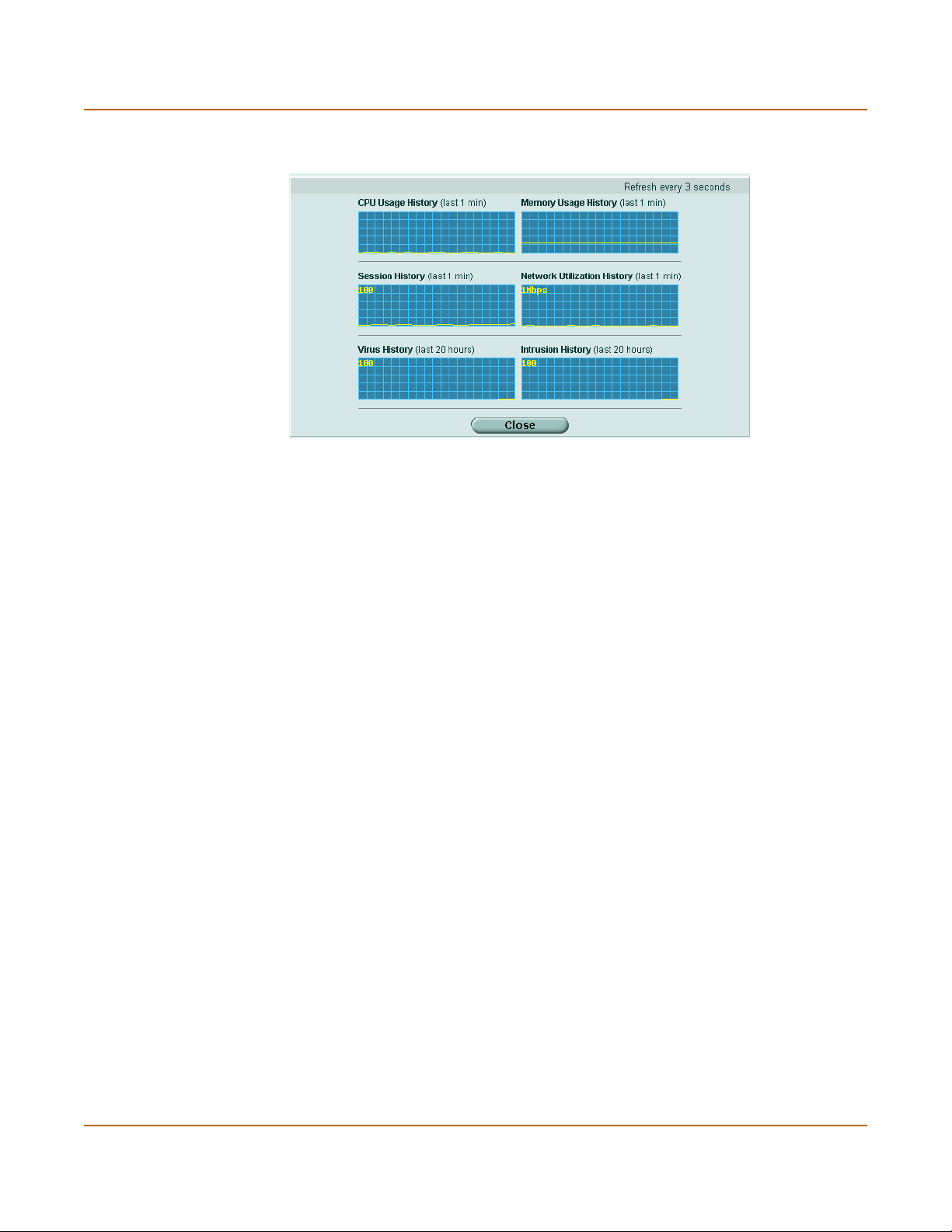
System status Changing unit information
Figure 3: Sample system resources history
History
The history page displays 6 graphs representing the following system resources and
protection:
CPU Usage History CPU usage for the previous minute.
Memory Usage History Memory usage for the previous minute.
Session History Session history for the previous minute.
Network Utilization
History
Virus History The virus detection history over the last 20 hours.
Intrusion History The intrusion detection history over the last 20 hours.
Recent Intrusion Detections
Time The time at which the recent intrusion was detected.
Src / Dst The source and destination addresses of the attack.
Service The service from which the attack was delivered; HTTP, FTP, IMAP,
Attack Name The name of the attack.
Changing unit information
Administrators with system configuration write access can use the unit information
area of the System Status page:
• To change FortiGate host name
• To update the firmware version
• To update the antivirus definitions manually
• To update the attack definitions manually
• To change to Transparent mode
• To change to NAT/Route mode
Network utilization for the previous minute.
POP3, or SMTP.
FortiGate-100A Administration Guide 01-28007-0068-20041203 29
Page 30

Changing unit information System status
To change FortiGate host name
The FortiGate host name appears on the Status page and in the FortiGate CLI
prompt. The host name is also used as the SNMP system name. For information
about the SNMP system name, see “SNMP” on page 97.
The default host name is FortiGate-100A.
Note: If the FortiGate unit is part of an HA cluster, you should set a unique name to distinguish
the unit from others in the cluster.
1 Go to System > Status > Status.
2 In the Host Name field of the Unit Information section, select Change.
3 In the New Name field, type a new host name.
4 Select OK.
The new host name is displayed in the Host Name field, and in the CLI prompt, and is
added to the SNMP System Name.
To update the firmware version
For information on updating the firmware, see “Changing the FortiGate firmware” on
page 33.
To update the antivirus definitions manually
Note: For information about configuring the FortiGate unit for automatic antivirus definitions
updates, see “Update center” on page 118.
1 Download the latest antivirus definitions update file from Fortinet and copy it to the
computer that you use to connect to the web-based manager.
2 Start the web-based manager and go to System > Status > Status.
3 In the Antivirus Definitions field of the Unit Information section, select Update.
4 In the Update File field, type the path and filename for the antivirus definitions update
file, or select Browse and locate the antivirus definitions update file.
5 Select OK to copy the antivirus definitions update file to the FortiGate unit.
The FortiGate unit updates the antivirus definitions. This takes about 1 minute.
6 Go to System > Status to confirm that the Antivirus Definitions Version information
has updated.
To update the attack definitions manually
Note: For information about configuring the FortiGate unit for automatic attack definitions
updates, see “Update center” on page 118.
1 Download the latest attack definitions update file from Fortinet and copy it to the
computer that you use to connect to the web-based manager.
2 Start the web-based manager and go to System > Status > Status.
30 01-28007-0068-20041203 Fortinet Inc.
Page 31

System status Changing unit information
3 In the Attack Definitions field of the Unit Information section, select Update.
The Intrusion Detection System Definitions Update dialog box appears.
4 In the Update File field, type the path and filename for the attack definitions update
file, or select Browse and locate the attack definitions update file.
5 Select OK to copy the attack definitions update file to the FortiGate unit.
The FortiGate unit updates the attack definitions. This takes about 1 minute.
6 Go to System > Status > Status to confirm that the Attack Definitions Version
information has updated.
To change to Transparent mode
After you change the FortiGate unit from the NAT/Route mode to Transparent mode,
most of the configuration resets to Transparent mode factory defaults, except for HA
settings (see “HA” on page 84).
1 Go to System > Status > Status.
2 In the Operation Mode field of the Unit Information section, select Change.
3 In the Operation Mode field, select Transparent.
4 Select OK.
The FortiGate unit changes operation mode.
5 To reconnect to the web-based manager, connect to the interface configured for
Transparent mode management access and browse to https:// followed by the
Transparent mode management IP address.
By default in Transparent mode, you can connect to port1. The default Transparent
mode management IP address is 10.10.10.1.
Note: If the web-based manager IP address was on a different subnet in NAT/Route mode, you
may have to change the IP address of your computer to the same subnet as the management
IP address.
To change to NAT/Route mode
After you change the FortiGate unit from the NAT/Route mode to Transparent mode,
most of the configuration resets to Transparent mode factory defaults, except for HA
settings (see “HA” on page 84).
1 Go to System > Status > Status.
2 In the Operation Mode field of the Unit Information section, select Change.
3 In the Operation Mode field, select NAT/Route.
4 Select OK.
The FortiGate unit changes operation mode.
5 To reconnect to the web-based manager, you must connect to the interface
configured by default for management access.
By default in NAT/Route mode, you can connect to port1. The default port1 IP address
is 192.168.1.99.
Note: If the management IP address was on a different subnet in Transparent mode, you may
have to change the IP address of your computer to the same subnet as the interface configured
for management access.
FortiGate-100A Administration Guide 01-28007-0068-20041203 31
Page 32

Changing unit information System status
Session list
The session list displays information about the communications sessions currently
being processed by the FortiGate unit. You can use the session list to view current
sessions.
Figure 4: Sample session list
From IP Set source IP address for list filtering
From Port Set source port for list filtering
To IP Set destination IP address for list filtering
To Po rt Set destination port for list filtering
Apply Filter Select to filter session list
Virtual Domain Select a virtual domain to list the sessions being processed by that virtual
Total Num ber of
Sessions
Protocol The service protocol of the connection, for example, udp, tcp, or icmp.
From IP The source IP address of the connection.
From Port The source port of the connection.
To IP The destination IP address of the connection.
To Po rt The destination port of the connection.
Expire The time, in seconds, before the connection expires.
domain. Select All to view sessions being processed by all virtual domains.
Total number of sessions currently being conducted through the FortiGate
unit.
Refresh icon. Select to update the session list
Page up icon. Select to view previous page in the session list
Page down icon. Select to view the next page in the session list.
Delete icon. Select to stop an active communication session.
To view the session list
1 Go to System > Status > Session.
The web-based manager displays the total number of active sessions in the FortiGate
unit session table and lists the top 16.
2 To navigate the list of sessions, select Page Up or Page Down.
3 Select Refresh to update the session list.
4 If you are logged in as an administrative user with read and write privileges or as the
admin user, you can select Delete to stop an active session.
32 01-28007-0068-20041203 Fortinet Inc.
Page 33

System status Upgrading to a new firmware version
Changing the FortiGate firmware
FortiGate administrators whose access profiles contain system configuration read and
write privileges and the FortiGate admin user can change the FortiGate firmware.
After you download a FortiGate firmware image from Fortinet, you can use the
procedures listed in Tab le 1 to install the firmware image on your FortiGate unit.
Table 1: Firmware upgrade procedures
Procedure Description
Upgrading to a new firmware version
Reverting to a
previous firmware
version
Installing firmware
images from a system
reboot using the CLI
Testing a new
firmware image before
installing it
Installing and using a
backup firmware
image
Use the web-based manager or CLI procedure to upgrade to a new
FortiOS firmware version or to a more recent build of the same
firmware version.
Use the web-based manager or CLI procedure to revert to a
previous firmware version. This procedure reverts the FortiGate
unit to its factory default configuration.
Use this procedure to install a new firmware version or revert to a
previous firmware version. To use this procedure you must connect
to the CLI using the FortiGate console port and a null-modem
cable. This procedure reverts the FortiGate unit to its factory
default configuration.
Use this procedure to test a new firmware image before installing it.
To use this procedure you must connect to the CLI using the
FortiGate console port and a null-modem cable. This procedure
temporarily installs a new firmware image using your current
configuration. You can test the firmware image before installing it
permanently. If the firmware image works correctly you can use
one of the other procedures listed in this table to install it
permanently.
If the FortiGate unit is running BIOS version v3.x, you can install a
backup firmware image. Once the backup firmware image is
installed you can switch to this backup image when required.
Upgrading to a new firmware version
Use the following procedures to upgrade the FortiGate unit to a newer firmware
version.
Upgrading the firmware using the web-based manager
Note: Installing firmware replaces the current antivirus and attack definitions with the definitions
included with the firmware release that you are installing. After you install new firmware, use the
procedure “To update antivirus and attack definitions” on page 120 to make sure that antivirus
and attack definitions are up to date.
To upgrade the firmware using the web-based manager
1 Copy the firmware image file to your management computer.
2 Log into the web-based manager as the admin administrative user.
Note: To use this procedure you must login using the admin administrator account, or an
administrator account that has system configuration read and write privileges.
FortiGate-100A Administration Guide 01-28007-0068-20041203 33
Page 34

Upgrading to a new firmware version System status
3 Go to System > Status.
4 Under Unit Information > Firmware Version, select Update.
5 Type the path and filename of the firmware image file, or select Browse and locate the
file.
6 Select OK.
The FortiGate unit uploads the firmware image file, upgrades to the new firmware
version, restarts, and displays the FortiGate login. This process takes a few minutes.
7 Log into the web-based manager.
8 Go to System > Status and check the Firmware Version to confirm that the firmware
upgrade is successfully installed.
9 Update antivirus and attack definitions. For information about updating antivirus and
attack definitions, see “Update center” on page 118.
Upgrading the firmware using the CLI
To use the following procedure you must have a TFTP server that the FortiGate unit
can connect to.
Note: Installing firmware replaces your current antivirus and attack definitions with the
definitions included with the firmware release that you are installing. After you install new
firmware, use the procedure “To update antivirus and attack definitions” on page 120 to make
sure that antivirus and attack definitions are up to date. You can also use the CLI command
execute update_now to update the antivirus and attack definitions.
To upgrade the firmware using the CLI
1 Make sure that the TFTP server is running.
2 Copy the new firmware image file to the root directory of the TFTP server.
3 Log into the CLI.
Note: To use this procedure you must login using the admin administrator account, or an
administrator account that has system configuration read and write privileges.
4 Make sure the FortiGate unit can connect to the TFTP server.
You can use the following command to ping the computer running the TFTP server.
For example, if the IP address of the TFTP server is 192.168.1.168:
execute ping 192.168.1.168
5 Enter the following command to copy the firmware image from the TFTP server to the
FortiGate unit:
execute restore image <name_str> <tftp_ipv4>
34 01-28007-0068-20041203 Fortinet Inc.
Page 35

System status Reverting to a previous firmware version
Where <name_str> is the name of the firmware image file and <tftp_ip> is the IP
address of the TFTP server. For example, if the firmware image file name is
FGT_300-v280-build183-FORTINET.out and the IP address of the TFTP server
is 192.168.1.168, enter:
execute restore image FGT_300-v280-build183-FORTINET.out
192.168.1.168
The FortiGate unit responds with the message:
This operation will replace the current firmware version!
Do you want to continue? (y/n)
6 Type y.
The FortiGate unit uploads the firmware image file, upgrades to the new firmware
version, and restarts. This process takes a few minutes.
7 Reconnect to the CLI.
8 To confirm that the new firmware image is successfully installed, enter:
get system status
9 Use the procedure “To update antivirus and attack definitions” on page 120 to update
antivirus and attack definitions, or from the CLI, enter:
execute update_now
Reverting to a previous firmware version
Use the following procedures to revert your FortiGate unit to a previous firmware
version.
Reverting to a previous firmware version using the web-based
manager
The following procedures revert the FortiGate unit to its factory default configuration
and deletes IPS custom signatures, web content lists, email filtering lists, and changes
to replacement messages.
Before beginning this procedure you can:
• Back up the FortiGate unit configuration.
• Back up the IPS custom signatures.
• Back up web content and email filtering lists.
For information, see “Backing up and Restoring” on page 116.
If you are reverting to a previous FortiOS version (for example, reverting from FortiOS
v2.80 to FortiOS v2.50), you might not be able to restore the previous configuration
from the backup configuration file.
Note: Installing firmware replaces the current antivirus and attack definitions with the definitions
included with the firmware release that you are installing. After you install new firmware, use the
procedure “To update antivirus and attack definitions” on page 120 to make sure that antivirus
and attack definitions are up to date.
To revert to a previous firmware version using the web-based manager
1 Copy the firmware image file to the management computer.
FortiGate-100A Administration Guide 01-28007-0068-20041203 35
Page 36

Reverting to a previous firmware version System status
2 Log into the FortiGate web-based manager.
Note: To use this procedure you must login using the admin administrator account, or an
administrator account that has system configuration read and write privileges.
3 Go to System > Status.
4 Under Unit Information > Firmware Version, select Update.
5 Type the path and filename of the firmware image file, or select Browse and locate the
file.
6 Select OK.
The FortiGate unit uploads the firmware image file, reverts to the old firmware version,
resets the configuration, restarts, and displays the FortiGate login. This process takes
a few minutes.
7 Log into the web-based manager.
8 Go to System > Status and check the Firmware Version to confirm that the firmware
is successfully installed.
9 Restore your configuration.
For information about restoring your configuration, see “Backup and restore” on
page 115.
10 Update antivirus and attack definitions.
For information about antivirus and attack definitions, see “To update antivirus and
attack definitions” on page 120.
Reverting to a previous firmware version using the CLI
This procedure reverts the FortiGate unit to its factory default configuration and
deletes IPS custom signatures, web content lists, email filtering lists, and changes to
replacement messages.
Before beginning this procedure you can:
• Back up the FortiGate unit system configuration using the command execute
backup config.
• Back up the IPS custom signatures using the command execute backup
ipsuserdefsig
• Back up web content and email filtering lists.
For information, see “Backing up and Restoring” on page 116.
If you are reverting to a previous FortiOS version (for example, reverting from FortiOS
v2.80 to FortiOS v2.50), you might not be able to restore your previous configuration
from the backup configuration file.
Note: Installing firmware replaces the current antivirus and attack definitions with the definitions
included with the firmware release that you are installing. After you install new firmware, use the
procedure “To update antivirus and attack definitions” on page 120 to make sure that antivirus
and attack definitions are up to date. You can also use the CLI command execute
update_now
to update the antivirus and attack definitions.
36 01-28007-0068-20041203 Fortinet Inc.
Page 37

System status Reverting to a previous firmware version
To use the following procedure you must have a TFTP server that the FortiGate unit
can connect to.
To revert to a previous firmware version using the CLI
1 Make sure that the TFTP server is running.
2 Copy the firmware image file to the root directory of the TFTP server.
3 Log into the FortiGate CLI.
Note: To use this procedure you must login using the admin administrator account, or an
administrator account that has system configuration read and write privileges.
4 Make sure the FortiGate unit can connect to the TFTP server.
You can use the following command to ping the computer running the TFTP server.
For example, if the TFTP server's IP address is 192.168.1.168:
execute ping 192.168.1.168
5 Enter the following command to copy the firmware image from the TFTP server to the
FortiGate unit:
execute restore image <name_str> <tftp_ipv4>
Where <name_str> is the name of the firmware image file and <tftp_ip> is the IP
address of the TFTP server. For example, if the firmware image file name is
FGT_300-v280-build158-FORTINET.out and the IP address of the TFTP server
is 192.168.1.168, enter:
execute restore image FGT_300-v280-build158-FORTINET.out
192.168.1.168
The FortiGate unit responds with the message:
This operation will replace the current firmware version!
Do you want to continue? (y/n)
6 Type y.
The FortiGate unit uploads the firmware image file. After the file uploads, a message
similar to the following is displayed:
Get image from tftp server OK.
Check image OK.
This operation will downgrade the current firmware version!
Do you want to continue? (y/n)
7 Type y.
The FortiGate unit reverts to the old firmware version, resets the configuration to
factory defaults, and restarts. This process takes a few minutes.
8 Reconnect to the CLI.
9 To confirm that the new firmware image has been loaded, enter:
get system status
10 To restore your previous configuration if needed, use the command:
execute restore config <name_str> <tftp_ipv4>
FortiGate-100A Administration Guide 01-28007-0068-20041203 37
Page 38

Installing firmware images from a system reboot using the CLI System status
11 Update antivirus and attack definitions.
For information, see “To update antivirus and attack definitions” on page 120, or from
the CLI, enter:
execute update_now
Installing firmware images from a system reboot using the CLI
This procedure installs a specified firmware image and resets the FortiGate unit to
default settings. You can use this procedure to upgrade to a new firmware version,
revert to an older firmware version, or re-install the current firmware version.
Note: This procedure varies for different FortiGate BIOS versions. These variations are
explained in the procedure steps that are affected. The version of the BIOS running on the
FortiGate unit is displayed when you restart the FortiGate unit using the CLI through a console
connection.
For this procedure you:
• access the CLI by connecting to the FortiGate console port using a null-modem
cable,
• install a TFTP server that you can connect to from port1. The TFTP server should
be on the same subnet as port1.
Before beginning this procedure you can:
• Back up the FortiGate unit configuration.
For information, see “Backing up and Restoring” on page 116.
• Back up the IPS custom signatures.
For information, see “Backing up and restoring custom signature files” on
page 283.
• Back up web content and email filtering lists.
For information, see “Web filter” on page 309 and “Spam filter” on page 323.
If you are reverting to a previous FortiOS version (for example, reverting from FortiOS
v2.80 to FortiOS v2.50), you might not be able to restore your previous configuration
from the backup configuration file.
Note: Installing firmware replaces the current antivirus and attack definitions with the definitions
included with the firmware release that you are installing. After you install new firmware, use the
procedure “To update antivirus and attack definitions” on page 120 to make sure that antivirus
and attack definitions are up to date.
To install firmware from a system reboot
1 Connect to the CLI using the null-modem cable and FortiGate console port.
2 Make sure that the TFTP server is running.
3 Copy the new firmware image file to the root directory of the TFTP server.
4 Make sure that port1 is connected to the same network as the TFTP server.
38 01-28007-0068-20041203 Fortinet Inc.
Page 39

System status Installing firmware images from a system reboot using the CLI
5 To confirm that the FortiGate unit can connect to the TFTP server, use the following
command to ping the computer running the TFTP server. For example, if the IP
address of the TFTP server is 192.168.1.168, enter:
execute ping 192.168.1.168
6 Enter the following command to restart the FortiGate unit:
execute reboot
The FortiGate unit responds with the following message:
This operation will reboot the system !
Do you want to continue? (y/n)
7 Type y.
As the FortiGate units starts, a series of system startup messages is displayed.
When one of the following messages appears:
• FortiGate unit running v2.x BIOS
Press Any Key To Download Boot Image.
...
• FortiGate unit running v3.x BIOS
Press any key to display configuration menu.....
......
Immediately press any key to interrupt the system startup.
Note: You have only 3 seconds to press any key. If you do not press a key soon enough, the
FortiGate unit reboots and you must log in and repeat the
execute reboot command.
If you successfully interrupt the startup process, one of the following messages
appears:
• FortiGate unit running v2.x BIOS
Enter TFTP Server Address [192.168.1.168]:
Go to step 9.
• FortiGate unit running v3.x BIOS
[G]: Get firmware image from TFTP server.
[F]: Format boot device.
[B]: Boot with backup firmware and set as default.
[Q]: Quit menu and continue to boot with default firmware.
[H]: Display this list of options.
Enter G,F,B,Q,or H:
8 Type G to get the new firmware image from the TFTP server.
The following message appears:
Enter TFTP server address [192.168.1.168]:
9 Type the address of the TFTP server and press Enter.
The following message appears:
Enter Local Address [192.168.1.188]:
FortiGate-100A Administration Guide 01-28007-0068-20041203 39
Page 40

Installing firmware images from a system reboot using the CLI System status
10 Type an IP address that the FortiGate unit can use to connect to the TFTP server.
The IP address can be any IP address that is valid for the network that the interface is
connected to. Make sure you do not enter the IP address of another device on this
network.
The following message appears:
Enter File Name [image.out]:
11 Enter the firmware image filename and press Enter.
The TFTP server uploads the firmware image file to the FortiGate unit and messages
similar to the following are displayed:
• FortiGate unit running v2.x BIOS
Do You Want To Save The Image? [Y/n]
Type Y.
• FortiGate unit running v3.x BIOS
Save as Default firmware/Run image without saving:[D/R]
or
Save as Default firmware/Backup firmware/Run image without
saving:[D/B/R]
12 Type D.
The FortiGate unit installs the new firmware image and restarts. The installation might
take a few minutes to complete.
Restoring the previous configuration
Change the internal interface address if required. You can do this from the CLI using
the command:
config system interface
edit internal
set ip <address_ipv4mask>
set allowaccess {ping https ssh telnet http}
end
After changing the interface address, you can access the FortiGate unit from the
web-based manager and restore the configuration.
• To restore the FortiGate unit configuration, see “Backup and restore” on page 115.
• To restore IPS custom signatures, see “Backing up and restoring custom signature
files” on page 283.
• To restore web content filtering lists, see “Backup and restore” on page 115.
• To restore email filtering lists, see “Backup and restore” on page 115.
• To update the virus and attack definitions to the most recent version, see “Updating
antivirus and attack definitions” on page 120.
If you are reverting to a previous firmware version (for example, reverting from
FortiOS v2.80 to FortiOS v2.50), you might not be able to restore your previous
configuration from the backup up configuration file.
40 01-28007-0068-20041203 Fortinet Inc.
Page 41

System status Testing a new firmware image before installing it
Testing a new firmware image before installing it
You can test a new firmware image by installing the firmware image from a system
reboot and saving it to system memory. After completing this procedure the FortiGate
unit operates using the new firmware image with the current configuration. This new
firmware image is not permanently installed. The next time the FortiGate unit restarts,
it operates with the originally installed firmware image using the current configuration.
If the new firmware image operates successfully, you can install it permanently using
the procedure “Upgrading to a new firmware version” on page 33.
For this procedure you:
• access the CLI by connecting to the FortiGate console port using a null-modem
cable,
• install a TFTP server that you can connect to from port1. The TFTP server should
be on the same subnet as port1.
To test a new firmware image
1 Connect to the CLI using a null-modem cable and FortiGate console port.
2 Make sure the TFTP server is running.
3 Copy the new firmware image file to the root directory of the TFTP server.
4 Make sure that port1 is connected to the same network as the TFTP server.
You can use the following command to ping the computer running the TFTP server.
For example, if the TFTP server's IP address is 192.168.1.168:
execute ping 192.168.1.168
5 Enter the following command to restart the FortiGate unit:
execute reboot
6 As the FortiGate unit reboots, press any key to interrupt the system startup.
As the FortiGate units starts, a series of system startup messages are displayed.
When one of the following messages appears:
• FortiGate unit running v2.x BIOS
Press Any Key To Download Boot Image.
...
• FortiGate unit running v3.x BIOS
Press any key to display configuration menu.....
......
7 Immediately press any key to interrupt the system startup.
Note: You have only 3 seconds to press any key. If you do not press a key soon enough, the
FortiGate unit reboots and you must log in and repeat the
FortiGate-100A Administration Guide 01-28007-0068-20041203 41
execute reboot command.
Page 42

Testing a new firmware image before installing it System status
If you successfully interrupt the startup process, one of the following messages
appears:
• FortiGate unit running v2.x BIOS
Enter TFTP Server Address [192.168.1.168]:
Go to step 9.
• FortiGate unit running v3.x BIOS
[G]: Get firmware image from TFTP server.
[F]: Format boot device.
[Q]: Quit menu and continue to boot with default firmware.
[H]: Display this list of options.
Enter G,F,Q,or H:
8 Type G to get the new firmware image from the TFTP server.
The following message appears:
Enter TFTP server address [192.168.1.168]:
9 Type the address of the TFTP server and press Enter.
The following message appears:
Enter Local Address [192.168.1.188]:
10 Type an IP address that can be used by the FortiGate unit to connect to the FTP
server.
The IP address must be on the same network as the TFTP server, but make sure you
do not use the IP address of another device on this network.
The following message appears:
Enter File Name [image.out]:
11 Enter the firmware image file name and press Enter.
The TFTP server uploads the firmware image file to the FortiGate unit and messages
similar to the following appear.
• FortiGate unit running v2.x BIOS
Do You Want To Save The Image? [Y/n]
Type N.
• FortiGate unit running v3.x BIOS
Save as Default firmware/Run image without saving:[D/R]
or
Save as Default firmware/Backup firmware/Run image without
saving:[D/B/R]
12 Type R.
The FortiGate image is installed to system memory and the FortiGate unit starts
running the new firmware image but with its current configuration.
13 You can log into the CLI or the web-based manager using any administrative account.
14 To confirm that the new firmware image has been loaded, from the CLI enter:
get system status
You can test the new firmware image as required.
42 01-28007-0068-20041203 Fortinet Inc.
Page 43

System status Installing and using a backup firmware image
Installing and using a backup firmware image
If the FortiGate unit is running BIOS version v3.x, you can install a backup firmware
image. Once the backup firmware image is installed you can switch to this backup
image when required.
• Installing a backup firmware image
• Switching to the backup firmware image
• Switching back to the default firmware image
Installing a backup firmware image
To run this procedure you:
• access the CLI by connecting to the FortiGate console port using a null-modem
cable,
• install a TFTP server that you can connect to from the FortiGate as described in
the procedure “Installing firmware images from a system reboot using the CLI” on
page 38.
To install a backup firmware image
1 Connect to the CLI using the null-modem cable and FortiGate console port.
2 Make sure that the TFTP server is running.
3 Copy the new firmware image file to the root directory of your TFTP server.
4 To confirm that the FortiGate unit can connect to the TFTP server, use the following
command to ping the computer running the TFTP server. For example, if the IP
address of the TFTP server is 192.168.1.168:
execute ping 192.168.1.168
5 Enter the following command to restart the FortiGate unit:
execute reboot
As the FortiGate unit starts, a series of system startup messages are displayed.
When of the following message appears:
Press any key to enter configuration menu.....
......
6 Immediately press any key to interrupt the system startup.
Note: You have only 3 seconds to press any key. If you do not press a key soon enough, the
FortiGate unit reboots and you must log in and repeat the execute reboot command.
If you successfully interrupt the startup process, the following message appears:
[G]: Get firmware image from TFTP server.
[F]: Format boot device.
[B]: Boot with backup firmware and set as default.
[Q]: Quit menu and continue to boot with default firmware.
[H]: Display this list of options.
Enter G,F,B,Q,or H:
FortiGate-100A Administration Guide 01-28007-0068-20041203 43
Page 44

Installing and using a backup firmware image System status
7 Type G to get the new firmware image from the TFTP server.
The following message appears:
Enter TFTP server address [192.168.1.168]:
8 Type the address of the TFTP server and press Enter.
The following message appears:
Enter Local Address [192.168.1.188]:
9 Type an IP address that can be used by the FortiGate unit to connect to the FTP
server.
The IP address can be any IP address that is valid for the network that the interface is
connected to. Make sure you do not enter the IP address of another device on this
network.
The following message appears:
Enter File Name [image.out]:
10 Enter the firmware image file name and press Enter.
The TFTP server uploads the firmware image file to the FortiGate unit and the
following message is displayed.
Save as Default firmware/Backup firmware/Run image without
saving:[D/B/R]
11 Type B.
The FortiGate unit saves the backup firmware image and restarts. When the FortiGate
unit restarts it is running the previously installed firmware version.
Switching to the backup firmware image
Use this procedure to switch the FortiGate unit to operating with a backup firmware
image that you previously installed. When you switch the FortiGate unit to the backup
firmware image, the FortiGate unit operates using the configuration that was saved
with that firmware image.
If you install a new backup image from a reboot, the configuration saved with this
firmware image is the factory default configuration. If you use the procedure
“Switching back to the default firmware image” on page 45 to switch to a backup
firmware image that was previously running as the default firmware image, the
configuration saved with this firmware image is restored.
To switch to the backup firmware image
1 Connect to the CLI using the null-modem cable and FortiGate console port.
2 Enter the following command to restart the FortiGate unit:
execute reboot
As the FortiGate units starts, a series of system startup messages are displayed.
When the following message appears:
Press any key to enter configuration menu.....
......
3 Immediately press any key to interrupt the system startup.
44 01-28007-0068-20041203 Fortinet Inc.
Page 45

System status Installing and using a backup firmware image
Note: You have only 3 seconds to press any key. If you do not press a key soon enough, the
FortiGate unit reboots and you must log in and repeat the
execute reboot command.
If you successfully interrupt the startup process, the following message appears:
[G]: Get firmware image from TFTP server.
[F]: Format boot device.
[B]: Boot with backup firmware and set as default.
[Q]: Quit menu and continue to boot with default firmware.
[H]: Display this list of options.
Enter G,F,B,Q,or H:
4 Type B to load the backup firmware image.
The FortiGate unit loads the backup firmware image and restarts. When the FortiGate
unit restarts, it is running the backup firmware version and the configuration is set to
factory default.
Switching back to the default firmware image
Use this procedure to switch the FortiGate unit to operating with the backup firmware
image that had been running as the default firmware image. When you switch to this
backup firmware image, the configuration saved with this firmware image is restored.
To switch back to the default firmware image
1 Connect to the CLI using the null-modem cable and FortiGate console port.
2 Enter the following command to restart the FortiGate unit:
execute reboot
As the FortiGate units starts, a series of system startup messages are displayed.
When the following message appears:
Press any key to enter configuration menu.....
......
3 Immediately press any key to interrupt the system startup.
Note: You have only 3 seconds to press any key. If you do not press a key soon enough, the
FortiGate unit reboots and you must log in and repeat the
execute reboot command.
If you successfully interrupt the startup process, the following message appears:
[G]: Get firmware image from TFTP server.
[F]: Format boot device.
[B]: Boot with backup firmware and set as default.
[Q]: Quit menu and continue to boot with default firmware.
[H]: Display this list of options.
Enter G,F,B,Q,or H:
4 Type B to load the backup firmware image.
The FortiGate unit loads the backup firmware image and restarts. When the FortiGate
unit restarts it is running the backup firmware version with a restored configuration.
FortiGate-100A Administration Guide 01-28007-0068-20041203 45
Page 46

Installing and using a backup firmware image System status
46 01-28007-0068-20041203 Fortinet Inc.
Page 47

FortiGate-100A Administration Guide Version 2.80 MR7
System network
System network settings control how the FortiGate unit connects to and interacts with
your network. Basic network settings start with configuring FortiGate interfaces to
connect to your network and configuring the FortiGate DNS settings.
More advanced network settings include adding VLAN subinterfaces and zones to the
FortiGate network configuration.
• Interface
• Zone
• Management
• DNS
• Routing table (Transparent Mode)
• VLAN overview
• VLANs in NAT/Route mode
• VLANs in Transparent mode
• FortiGate IPv6 support
Interface
In NAT/Route mode, go to System > Network > Interface to configure FortiGate
interfaces and to add and configure VLAN subinterfaces.
Note: Unless stated otherwise, in this section the term interface can refer to a physical
FortiGate interface or to a FortiGate VLAN subinterface.
• For information about VLANs in NAT/Route mode, see “VLANs in NAT/Route
mode” on page 64.
• For information about VLANs in Transparent mode, see “VLANs in Transparent
mode” on page 66.
FortiGate-100A Administration Guide 01-28007-0068-20041203 47
Page 48

Interface settings System network
Figure 5: Interface list
Create New Select Create New to create a VLAN.
Virtual Domain Select a virtual domain to display the interfaces added to this virtual domain.
Name The names of the physical interfaces available to your FortiGate unit.
IP The current IP address of the interface.
Netmask The netmask of the interface.
Access The administrative access configuration for the interface.
Status The administrative status for the interface.
Only available if you have added a virtual domain.
• Interface names indicate the default function of the interface (For
example, internal, dmz1, dmz2, wan1 and wan2)
If you have added VLAN subinterfaces, they also appear in the name list,
below the physical interface that they have been added to. See “VLAN
overview” on page 63.
See “To control administrative access to an interface” on page 57 for
information about administrative access options.
If the administrative status is a green arrow, the interface is up and can
accept network traffic. If the administrative status is a red arrow, the
interface is administratively down and cannot accept traffic. To change the
administrative status, select Bring Down or Bring Up. For more information,
see “To bring down an interface that is administratively up” on page 54 and
“To start up an interface that is administratively down” on page 54.
Delete, edit, and view icons.
Interface settings
Interface settings displays the current configuration of a selected FortiGate interface
or VLAN subinterface. Use interface settings to configure a new VLAN subinterface or
to change the configuration of a FortiGate interface or VLAN subinterface.
48 01-28007-0068-20041203 Fortinet Inc.
Page 49

System network Interface settings
Figure 6: Interface settings
See the following procedures for configuring interfaces:
• To bring down an interface that is administratively up
• To start up an interface that is administratively down
• To add interfaces to a zone
• To add an interface to a virtual domain
• To change the static IP address of an interface
• To configure an interface for DHCP
• To configure an interface for PPPoE
• To configure support for dynamic DNS services
• To add a secondary IP address
• To add a ping server to an interface
• To control administrative access to an interface
• To change the MTU size of the packets leaving an interface
• To configure traffic logging for connections to an interface
Name
The name of the Interface.
Interface
Select the name of the physical interface to add the VLAN subinterface to. All VLAN
subinterfaces must be associated with a physical interface. Once created, the VLAN is
listed below its physical interface in the Interface list.
VLAN ID
Enter the VLAN ID that matches the VLAN ID of the packets to be received by this
VLAN subinterface. You cannot change the VLAN ID of an existing VLAN
subinterface.
FortiGate-100A Administration Guide 01-28007-0068-20041203 49
Page 50

Interface settings System network
The VLAN ID can be any number between 1 and 4096 and must match the VLAN ID
added by the IEEE 802.1Q-compliant router or switch connected to the VLAN
subinterface.
For more information on VLANs, see “VLAN overview” on page 63.
Virtual Domain
Select a virtual domain to add the interface or VLAN subinterface to this virtual
domain. Virtual domain is only available if you have added a virtual domain.
For more information on virtual domains, see “System virtual domain” on page 131.
Addressing mode
Select Manual, DHCP, or PPPoE to set the addressing mode for this interface.
Manual
Select Manual and enter an IP address and netmask for the interface. The IP address
of the interface must be on the same subnet as the network the interface is connecting
to.
Note: Where you can enter both an IP address and a netmask in the same field, you can use
the short form of the netmask. For example, 192.168.1.100/255.255.255.0 can also be entered
as 192.168.1.100/24.
Two interfaces cannot have the same IP address and cannot have IP addresses on
the same subnet.
DHCP
If you configure the interface to use DHCP, the FortiGate unit automatically
broadcasts a DHCP request. You can disable Connect to server if you are configuring
the FortiGate unit offline and you do not want the FortiGate unit to send the DHCP
request.
Distance Enter the administrative distance for the default gateway retrieved from
Retrieve default
gateway from server
Override internal DNS Enable Override internal DNS to use the DNS addresses retrieved
Connect to server Enable Connect to Server so that the interface automatically attempts
Status Displays DHCP status messages as the FortiGate unit connects to the
the DHCP server. The administrative distance, an integer from 1-255,
specifies the relative priority of a route when there are multiple routes
to the same destination. A lower administrative distance indicates a
more preferred route. The default distance for the default gateway is 1.
Enable Retrieve default gateway from server to retrieve a default
gateway IP address from the DHCP server. The default gateway is
added to the static routing table.
from the DHCP server instead of the DNS server IP addresses on the
DNS page.
You should also enable Obtain DNS server address automatically in
System > Network > DNS. See “DNS” on page 61.
to connect to a DHCP server. Disable this option if you are configuring
the interface offline.
DHCP server and gets addressing information. Select Status to refresh
the addressing mode status message.
50 01-28007-0068-20041203 Fortinet Inc.
Page 51

System network Interface settings
initializing No activity.
connecting The interface is attempting to connect to the DHCP server.
connected The interface retrieves an IP address, netmask, and other settings
failed The interface was unable to retrieve an IP address and other
from the DHCP server.
information from the DHCP server.
PPPoE
If you configure the interface to use PPPoE, the FortiGate unit automatically
broadcasts a PPPoE request. You can disable connect to server if you are configuring
the FortiGate unit offline and you do not want the FortiGate unit to send the PPPoE
request.
FortiGate units support many of the PPPoE RFC features (RFC 2516) including
unnumbered IPs, initial discovery timeout that times and PPPoE Active Discovery
Terminate (PADT).
Figure 7: PPPoE settings
User Name The PPPoE account user name.
Password The PPPoE account password.
Unnumbered IP Specify the IP address for the interface. If your ISP has assigned you a
Initial Disc
Timeout
Initial PADT
timeout
Distance Enter the administrative distance for the default gateway retrieved from the
Retrieve default
gateway from
server
Override internal
DNS
FortiGate-100A Administration Guide 01-28007-0068-20041203 51
block of IP addresses, use one of them. Otherwise, this IP address can be
the same as the IP address of another interface or can be any IP address.
Initial discovery timeout. The time to wait before retrying to start a PPPoE
discovery. Set Initial Disc to 0 to disable.
Initial PPPoE Active Discovery Terminate (PADT) timeout in seconds. Use
this timeout to shut down the PPPoE session if it is idle for this number of
seconds. PADT must be supported by your ISP. Set initial PADT timeout to
0 to disable.
PPPoE server. The administrative distance, an integer from 1-255,
specifies the relative priority of a route when there are multiple routes to the
same destination. A lower administrative distance indicates a more
preferred route. The default distance for the default gateway is 1.
Enable Retrieve default gateway from server to retrieve a default gateway
IP address from a PPPoE server. The default gateway is added to the static
routing table.
Enable Override internal DNS to replace the DNS server IP addresses on
the DNS page with the DNS addresses retrieved from the PPPoE server.
Page 52

Interface settings System network
Connect to server Enable Connect to Server so that the interface automatically attempts to
Status Displays PPPoE status messages as the FortiGate unit connects to the
initializing No activity.
connecting The interface is attempting to connect to the PPPoE server.
connected The interface retrieves an IP address, netmask, and other settings from the
failed The interface was unable to retrieve an IP address and other information
connect to a PPPoE server. Disable this option if you are configuring the
interface offline.
PPPoE server and gets addressing information. Select Status to refresh the
addressing mode status message.
PPPoE server.
from the PPPoE server.
DDNS
Enable or disable updates to a Dynamic DNS (DDNS) service. When the FortiGate
unit has a static domain name and a dynamic public IP address, select DDNS Enable
to force the unit to update the DDNS server each time the address changes. In turn,
the DDNS service updates Internet DNS servers with the new IP address for the
domain.
Dynamic DNS is available only in NAT/Route mode.
Server Select a DDNS server to use. The client software for these services is built into the
Domain The domain name to use for the DDNS service.
Username The user name to use when connecting to the DDNS server.
Password The password to use when connecting to the DDNS server.
FortiGate firmware. The FortiGate unit can only connect automatically to a DDNS
server for the supported clients.
Ping server
Add a ping server to an interface if you want the FortiGate unit to confirm connectivity
with the next hop router on the network connected to the interface. Adding a ping
server is required for routing failover. See “To add or edit a static route” on page 144.
The FortiGate unit uses dead gateway detection to ping the Ping Server IP address to
make sure that the FortiGate unit can connect to this IP address. To configure dead
gateway detection, see “To modify the dead gateway detection settings” on page 84.
Administrative access
Configure administrative access to an interface to control how administrators access
the FortiGate unit and the FortiGate interfaces to which administrators can connect.
You can select the following administrative access options:
HTTPS To allow secure HTTPS connections to the web-based manager through this
PING If you want this interface to respond to pings. Use this setting to verify your
HTTP To allow HTTP connections to the web-based manager through this interface.
interface.
installation and for testing.
HTTP connections are not secure and can be intercepted by a third party.
52 01-28007-0068-20041203 Fortinet Inc.
Page 53

System network Configuring interfaces
SSH To allow SSH connections to the CLI through this interface.
SNMP To allow a remote SNMP manager to request SNMP information by connecting to
TELNET To allow Telnet connections to the CLI through this interface. Telnet connections
this interface. See “Configuring SNMP” on page 98.
are not secure and can be intercepted by a third party.
MTU
To improve network performance, you can change the maximum transmission unit
(MTU) of the packets that the FortiGate unit transmits from any interface. Ideally, this
MTU should be the same as the smallest MTU of all the networks between the
FortiGate unit and the destination of the packets. If the packets that the FortiGate unit
sends are larger, they are broken up or fragmented, which slows down transmission.
Experiment by lowering the MTU to find an MTU size for best network performance.
To change the MTU, select Override default MTU value (1500) and enter the
maximum packet size. For manual and DHCP addressing mode the MTU size can be
from 576 to 1500 bytes. For PPPoE addressing mode the MTU size can be from 576
to 1492 bytes.
Note: In Transparent mode, if you change the MTU of an interface, you must change the MTU
of all interfaces to match the new MTU.
Log
Select Log to record logs for any traffic to or from the interface. To record logs you
must also enable traffic log for a logging location and set the logging severity level to
Notification or lower. Go to Log & Report > Log Config to configure logging locations
and types. For information about logging see “Log & Report” on page 339.
Configuring interfaces
Use the following procedures to configure FortiGate interfaces and VLAN
subinterfaces.
• To bring down an interface that is administratively up
• To add interfaces to a zone
• To add an interface to a virtual domain
• To change the static IP address of an interface
• To configure an interface for DHCP
• To configure an interface for PPPoE
• To add a secondary IP address
• To configure support for dynamic DNS services
• To add a ping server to an interface
• To control administrative access to an interface
• To change the MTU size of the packets leaving an interface
• To configure traffic logging for connections to an interface
FortiGate-100A Administration Guide 01-28007-0068-20041203 53
Page 54

Configuring interfaces System network
To add a VLAN subinterface
See “To add a VLAN subinterface in NAT/Route mode” on page 65.
To bring down an interface that is administratively up
You can bring down physical interfaces or VLAN subinterfaces. Bringing down a
physical interface also brings down the VLAN subinterfaces associated with it.
1 Go to System > Network > Interface.
The interface list is displayed.
2 Select Bring Down for the interface that you want to stop.
To start up an interface that is administratively down
You can start up physical interfaces and VLAN subinterfaces. Starting a physical
interface does not start the VLAN subinterfaces added to it.
1 Go to System > Network > Interface.
The interface list is displayed.
2 Select Bring Up for the interface that you want to start.
To add interfaces to a zone
If you have added zones to the FortiGate unit, you can use this procedure to add
interfaces or VLAN subinterfaces to the zone. To add a zone, see “To add a zone” on
page 59. You cannot add an interface to a zone if you have added firewall policies for
the interface. Delete firewall policies for the interface and then add the interface to the
zone.
1 Go to System > Network > Zone.
2 Choose the zone to add the interface or VLAN subinterface to and select Edit.
3 Select the names of the interfaces or VLAN subinterfaces to add to the zone.
4 Select OK to save the changes.
To add an interface to a virtual domain
If you have added virtual domains to the FortiGate unit, you can use this procedure to
add an interface or VLAN subinterface to a virtual domain. To add a virtual domain,
see “To add a virtual domain” on page 135. You cannot add an interface to a virtual
domain if you have added firewall policies for the interface. Delete firewall policies for
the interface and then add the interface to the virtual domain.
1 Go to System > Network > Interface.
2 Choose the interface or VLAN subinterface to add to a virtual domain and select Edit.
3 From the Virtual Domain list, select the virtual domain that you want to add the
interface to.
4 Select OK to save the changes.
5 Repeat these steps to add more interfaces or VLAN subinterfaces to virtual domains.
54 01-28007-0068-20041203 Fortinet Inc.
Page 55

System network Configuring interfaces
To change the static IP address of an interface
You can change the static IP address of any FortiGate interface.
1 Go to System > Network > Interface.
2 Choose an interface and select Edit.
3 Set Addressing Mode to Manual.
4 Change the IP address and Netmask as required.
5 Select OK to save your changes.
If you changed the IP address of the interface to which you are connecting to manage
the FortiGate unit, you must reconnect to the web-based manager using the new
interface IP address.
To configure an interface for DHCP
You can configure any FortiGate interface to use DHCP.
1 Go to System > Network > Interface.
2 Choose an interface and select Edit.
3 In the Addressing Mode section, select DHCP.
4 Select the Retrieve default gateway and DNS from server check box if you want the
FortiGate unit to obtain a default gateway IP address and DNS server IP addresses
from the DHCP server.
5 Select the Connect to Server check box if you want the FortiGate unit to connect to
the DHCP server.
6 Select Apply.
The FortiGate unit attempts to contact the DHCP server from the interface to set the
IP address, netmask, and optionally the default gateway IP address, and DNS server
IP addresses.
7 Select Status to refresh the addressing mode status message.
8 Select OK.
To configure an interface for PPPoE
Use this procedure to configure any FortiGate interface to use PPPoE. See “PPPoE”
on page 51 for information on PPPoE settings.
1 Go to System > Network > Interface.
2 Choose an interface and select Edit.
3 In the Addressing Mode section, select PPPoE.
4 Enter your PPPoE account User Name and Password.
5 Enter an Unnumbered IP if required by your PPPoE service.
6 Set the Initial Disc Timeout and Initial PADT Timeout if supported by your ISP.
7 Select the Retrieve default gateway from server check box if you want the FortiGate
unit to obtain a default gateway IP address from the PPPoE server.
8 Select the Override Internal DNS check box if you want the FortiGate unit to obtain a
DNS server IP address from the PPPoE server.
FortiGate-100A Administration Guide 01-28007-0068-20041203 55
Page 56

Configuring interfaces System network
9 Select the Connect to Server check box if you want the FortiGate unit to connect to
the PPPoE server.
10 Select Apply.
The FortiGate unit attempts to contact the PPPoE server from the interface to set the
IP address, netmask, and optionally default gateway IP address and DNS server IP
addresses.
11 Select Status to refresh the addressing mode status message.
12 Select OK.
To add a secondary IP address
You can use the CLI to add a secondary IP address to any FortiGate interface. The
secondary IP address cannot be the same as the primary IP address but it can be on
the same subnet.
From the FortiGate CLI, enter the following commands:
config system interface
edit <intf_str>
config secondaryip
edit 0
set ip <second_ip> <netmask_ip>
Optionally, you can also configure management access and add a ping server to the
secondary IP address:
set allowaccess ping https ssh snmp http telnet
set gwdetect enable
Save the changes:
end
To configure support for dynamic DNS services
1 Go to System > Network > Interface.
2 Select the interface to the Internet and then select Edit.
3 Select DDNS Enable.
4 From the Server list, select one of the supported dynamic DNS services.
5 In the Domain field, type the fully qualified domain name of the FortiGate unit.
6 In the Username field, type the user name that the FortiGate unit must send when it
connects to the dynamic DNS server.
7 In the Password field, type the associated password.
8 Select OK.
To add a ping server to an interface
1 Go to System > Network > Interface.
2 Choose an interface and select Edit.
56 01-28007-0068-20041203 Fortinet Inc.
Page 57

System network Configuring interfaces
3 Set Ping Server to the IP address of the next hop router on the network connected to
the interface.
4 Select the Enable check box.
5 Select OK to save the changes.
To control administrative access to an interface
For a FortiGate unit running in NAT/Route mode, you can control administrative
access to an interface to control how administrators access the FortiGate unit and the
FortiGate interfaces to which administrators can connect.
Controlling administrative access for an interface connected to the Internet allows
remote administration of the FortiGate unit from any location on the Internet. However,
allowing remote administration from the Internet could compromise the security of
your FortiGate unit. You should avoid allowing administrative access for an interface
connected to the Internet unless this is required for your configuration. To improve the
security of a FortiGate unit that allows remote administration from the Internet:
• Use secure administrative user passwords,
• Change these passwords regularly,
• Enable secure administrative access to this interface using only HTTPS or SSH,
• Do not change the system idle timeout from the default value of 5 minutes (see “To
set the system idle timeout” on page 83).
To configure administrative access in Transparent mode, see “To configure the
management interface” on page 60.
1 Go to System > Network > Interface.
2 Choose an interface and select Edit.
3 Select the Administrative Access methods for the interface.
4 Select OK to save the changes.
To change the MTU size of the packets leaving an interface
1 Go to System > Network > Interface.
2 Choose an interface and select Edit.
3 Select Override default MTU value (1500).
4 Set the MTU size.
Note: You cannot set the MTU of a VLAN larger than the MTU of its physical interface. Nor can
you set the MTU of a physical interface smaller than the MTU of any VLAN on that interface.
To configure traffic logging for connections to an interface
1 Go to System > Network > Interface.
2 Choose an interface and select Edit.
3 Select the Log check box to record log messages whenever a firewall policy accepts a
connection to this interface.
4 Select OK to save the changes.
FortiGate-100A Administration Guide 01-28007-0068-20041203 57
Page 58

Zone settings System network
Zone
You can use zones to group related interfaces and VLAN subinterfaces. Grouping
interfaces and VLAN subinterfaces into zones simplifies policy creation. If you group
interfaces and VLAN subinterfaces into a zone, you can configure policies for
connections to and from this zone, rather than to and from each interface and VLAN
subinterface.
You can add zones, rename and edit zones, and delete zones from the zone list.
When you add a zone, you select the names of the interfaces and VLAN subinterfaces
to add to the zone.
Zones are added to virtual domains. If you have added multiple virtual domains to
your FortiGate configuration, make sure you are configuring the correct virtual domain
before adding or editing zones.
Figure 8: Zone list
Zone settings
Create New Select Create New to create a zone.
Name The names of the zones that you have added.
Block intra-zone
traffic
Interface Members The names of the interfaces added to the zone.
Figure 9: Zone options
Name Enter the name to identify the zone.
Block intra-zone
traffic
Interface members Enable check boxes to select the interfaces that are part of this zone.
Displays Yes if traffic between interfaces in the same zone is blocked and
No if traffic between interfaces in the same zone is not blocked.
Edit/View icons. Select to edit or view a zone.
Delete icon. Select to remove a zone.
Select Block intra-zone traffic to block traffic between interfaces or VLAN
subinterfaces in the same zone.
58 01-28007-0068-20041203 Fortinet Inc.
Page 59

System network Zone settings
To add a zone
1 If you have added a virtual domain, go to System > Virtual Domain > Current
Virtual Domain and select the virtual domain to which you want to add the zone.
2 Go to System > Network > Zone.
3 Select Create New.
4 In the New Zone dialog box, type a name for the zone.
5 Select the Block intra-zone traffic check box if you want to block traffic between
interfaces or VLAN subinterfaces in the same zone.
6 Select the names of the interfaces or VLAN subinterfaces to add to the zone.
7 Select OK.
To delete a zone
You can only delete zones that have the Delete icon beside them in the zone list.
1 If you have added a virtual domain, go to System > Virtual Domain > Current
Virtual Domain and select the virtual domain from which to delete the zone.
2 Go to System > Network > Zone.
3 Select Delete to remove a zone from the list.
Management
4 Select OK to delete the zone.
To edit a zone
1 If you have added a virtual domain, go to System > Virtual Domain > Current
Virtual Domain and select the virtual domain in which to edit the zone.
2 Go to System > Network > Zone.
3 Select Edit to modify a zone.
4 Select or deselect Block intra-zone traffic.
5 Select the names of the interfaces or VLAN subinterfaces to add to the zone.
6 Clear the check box for the names of the interfaces or VLAN subinterfaces to remove
from the zone.
7 Select OK.
Configure the management interface in Transparent mode to set the management IP
address of the FortiGate unit. Administrators connect to this IP address to administer
the FortiGate unit. The FortiGate also uses this IP address to connect to the FDN for
virus and attack updates (see “Update center” on page 118).
You can also configure interfaces to control how administrators connect to the
FortiGate unit for administration. See “To control administrative access to an interface”
on page 57.
FortiGate-100A Administration Guide 01-28007-0068-20041203 59
Page 60

Zone settings System network
Controlling administrative access to a FortiGate interface connected to the Internet
allows remote administration of the FortiGate unit from any location on the Internet.
However, allowing remote administration from the Internet could compromise the
security of the FortiGate unit. You should avoid allowing administrative access for an
interface connected to the Internet unless this is required for your configuration. To
improve the security of a FortiGate unit that allows remote administration from the
Internet:
• Use secure administrative user passwords,
• Change these passwords regularly,
• Enable secure administrative access to this interface using only HTTPS or SSH,
• Do not change the system idle timeout from the default value of 5 minutes (see “To
set the system idle timeout” on page 83).
Figure 10: Management
Management
IP/Netmask
Default
Gateway
Management
Virtual Domain
Enter the management IP address and netmask. This must be a valid IP
address for the network that you want to manage the FortiGate unit
from.
Enter the default gateway address.
Select the virtual domain from which you want to perform system
management.
To configure the management interface
1 Go to System > Network > Management.
2 Enter the Management IP/Netmask.
3 Enter the Default Gateway.
4 Select the Management Virtual Domain.
5 Select Apply.
The FortiGate unit displays the following message:
Management IP address was changed. Click here to redirect.
6 Click on the message to connect to the new Management IP.
60 01-28007-0068-20041203 Fortinet Inc.
Page 61

System network Zone settings
DNS
Several FortiGate functions, including Alert E-mail and URL blocking, use DNS. You
can add the IP addresses of the DNS servers to which your FortiGate unit can
connect. DNS server IP addresses are usually supplied by your ISP.
You can configure primary and secondary DNS server addresses, or you can
configure the FortiGate unit to obtain DNS server addresses automatically. To obtain
addresses automatically, at least one interface must use the DHCP or PPPoE
addressing mode. See “DHCP” on page 50. See “PPPoE” on page 51.
If you enable DNS Forwarding on an interface, hosts on the attached network can use
the interface IP address as their DNS server. DNS requests sent to the interface are
forwarded to the DNS server addresses you configured or that the FortiGate unit
obtained automatically.
Figure 11: DNS
Obtain DNS server
address automatically
Primary DNS Server Enter the primary DNS server IP address.
Secondary DNS Server Enter the secondary DNS server IP address.
Enable DNS
forwarding from
When DHCP is used on an interface, also obtain the DNS server IP
address. Available only in NAT/Route mode. You should also enable
Override internal DNS in the DHCP settings of the interface. See
“DHCP” on page 50.
Enable the check boxes of the interfaces to which DNS Forwarding
applies. Available only in NAT/Route mode.
To add DNS server IP addresses
1 Go to System > Network > DNS.
2 Change the primary and secondary DNS server IP addresses as required.
3 Select Apply to save the changes.
FortiGate-100A Administration Guide 01-28007-0068-20041203 61
Page 62

Routing table list System network
Routing table (Transparent Mode)
In Transparent mode, you can configure routing to add static routes from the FortiGate
unit to local routers.
Routing table list
Figure 12: Routing table
Create New Select Create New to add a new route.
# Route number.
IP The destination IP address for this route.
Mask The netmask for this route.
Gateway The IP address of the next hop router to which this route directs traffic.
Distance The the relative preferability of this route. 1 is most preferred.
Delete icon. Select to remove a route.
View/edit icon. Select to view or edit a route.
Move To icon. Select to change the order of a route in the list.
Transparent mode route settings
Figure 13: Transparent mode route options
Destination IP
/Mask
Gateway Enter the IP address of the next hop router to which this route directs traffic
Distance The the relative preferability of this route. 1 is most preferred.
To add a Transparent mode route
1 Go to System > Network > Routing Table.
2 Select Create New to add a new route.
3 Set the Destination IP and Mask to 0.0.0.0.
For the default route, set the Destination IP and Mask to 0.0.0.0.
Note: Only one default route can be active at a time. If two default routes are added to the
routing table, only the default route closest to the top of the routing table is active.
Enter the destination IP address and netmask for this route.
62 01-28007-0068-20041203 Fortinet Inc.
Page 63

System network Transparent mode route settings
4 Set Gateway to the IP address of the next hop routing gateway.
For an Internet connection, the next hop routing gateway routes traffic to the Internet.
5 Select OK to save the route.
VLAN overview
A VLAN is group of PCs, servers, and other network devices that communicate as if
they were on the same LAN segment, even though they may not be. For example, the
workstations and servers for an accounting department could be scattered throughout
an office, connected to numerous network segments, but they can still belong to the
same VLAN.
A VLAN segregates devices logically instead of physically. Each VLAN is treated as a
broadcast domain. Devices in VLAN 1 can connect with other devices in VLAN 1, but
cannot connect with devices in other VLANs. The communication among devices on a
VLAN is independent of the physical network.
A VLAN segregates devices by adding 802.1Q VLAN tags to all of the packets sent
and received by the devices in the VLAN. VLAN tags are 4-byte frame extensions that
contain a VLAN identifier as well as other information.
VLANs allow highly flexible, efficient network segmentation, enabling users and
resources to be grouped logically, regardless of physical locations.
Figure 14: Basic VLAN topology
Internet
Untagged
packets
Esc Enter
VLAN trunk
VLAN 1
VLAN 2
POWER
VLAN 1
VLAN 1 network VLAN 2 network
Firewall or
Router
VLAN Switch or router
VLAN 2
FortiGate-100A Administration Guide 01-28007-0068-20041203 63
Page 64

FortiGate units and VLANs System network
FortiGate units and VLANs
In a typical VLAN configuration, 802.1Q-compliant VLAN layer-2 switches or layer-3
routers or firewalls add VLAN tags to packets. Packets passing between devices in
the same VLAN can be handled by layer 2 switches. Packets passing between
devices in different VLANs must be handled by a layer 3 device such as router,
firewall, or layer 3 switch.
Using VLANs, a single FortiGate unit can provide security services and control
connections between multiple security domains. Traffic from each security domain is
given a different VLAN ID. The FortiGate unit can recognize VLAN IDs and apply
security policies to secure network and IPSec VPN traffic between security domains.
The FortiGate unit can also apply authentication, protection profiles, and other firewall
policy features for network and VPN traffic that is allowed to pass between security
domains.
VLANs in NAT/Route mode
Operating in NAT/Route mode, the FortiGate unit functions as a layer 3 device to
control the flow of packets between VLANs. The FortiGate unit can also remove VLAN
tags from incoming VLAN packets and forward untagged packets to other networks,
such as the Internet.
In NAT/Route mode, the FortiGate units support VLANs for constructing VLAN trunks
between an IEEE 802.1Q-compliant switch (or router) and the FortiGate unit. Normally
the FortiGate unit internal interface connects to a VLAN trunk on an internal switch,
and the external interface connects to an upstream Internet router untagged. The
FortiGate unit can then apply different policies for traffic on each VLAN that connects
to the internal interface.
In this configuration, you add VLAN subinterfaces to the FortiGate internal interface
that have VLAN IDs that match the VLAN IDs of packets in the VLAN trunk. The
FortiGate unit directs packets with VLAN IDs, to subinterfaces with matching VLAN
IDs.
You can also define VLAN subinterfaces on all FortiGate interfaces. The FortiGate
unit can add VLAN tags to packets leaving a VLAN subinterface or remove VLAN tags
from incoming packets and add a different VLAN tags to outgoing packets.
Rules for VLAN IDs
In NAT/Route mode, two VLAN subinterfaces added to the same physical interface
cannot have the same VLAN ID. However, you can add two or more VLAN
subinterfaces with the same VLAN IDs to different physical interfaces. There is no
internal connection or link between two VLAN subinterfaces with same VLAN ID. Their
relationship is the same as the relationship between any two FortiGate network
interfaces.
Rules for VLAN IP addresses
IP addresses of all FortiGate interfaces cannot overlap. That is, the IP addresses of all
interfaces must be on different subnets. This rule applies to both physical interfaces
and to VLAN subinterfaces.
64 01-28007-0068-20041203 Fortinet Inc.
Page 65

System network Adding VLAN subinterfaces
Note: If you are unable to change your existing configurations to prevent IP overlap, enter the
CLI command config system global and set ip-overlap enable to allow IP address
overlap. If you enter this command, multiple VLAN interfaces can have an IP address that is
part of a subnet used by another interface. This command is recommended for advanced users
only.
Figure 15 shows a simplified NAT/Route mode VLAN configuration. In this example,
FortiGate internal interface connects to a VLAN switch using an 802.1Q trunk and is
configured with two VLAN subinterfaces (VLAN 100 and VLAN 200). The external
interface connects to the Internet. The external interface is not configured with VLAN
subinterfaces.
When the VLAN switch receives packets from VLAN 100 and VLAN 200, it applies
VLAN tags and forwards the packets to local ports and across the trunk to the
FortiGate unit. The FortiGate unit is configured with policies that allow traffic to flow
between the VLANs and from the VLANs to the external network.
Figure 15: FortiGate unit in Nat/Route mode
POWER
Fa0/3 Fa0/9 Fa0/24
VLAN switch
802.1Q Trunk
FortiGate
Esc Enter
Internal
192.168.110.126
External
172.16.21.2
VLAN 100 VLAN 200
VLAN 100 network
10.1.1.0
10.1.1.2
Adding VLAN subinterfaces
The VLAN ID of each VLAN subinterface must match the VLAN ID added by the IEEE
802.1Q-compliant router. The VLAN ID can be any number between 1 and 4096.
Each VLAN subinterface must also be configured with its own IP address and
netmask.
Note: A VLAN must not have the same name as a virtual domain or zone.
You add VLAN subinterfaces to the physical interface that receives VLAN-tagged
packets.
To add a VLAN subinterface in NAT/Route mode
1 Go to System > Network > Interface.
2 Select Create New to add a VLAN subinterface.
3 Enter a Name to identify the VLAN subinterface.
VLAN 200 network
10.1.2.0
10.1.2.2
Internet
4 Select the physical interface that receives the VLAN packets intended for this VLAN
subinterface.
FortiGate-100A Administration Guide 01-28007-0068-20041203 65
Page 66

Adding VLAN subinterfaces System network
5 Enter the VLAN ID that matches the VLAN ID of the packets to be received by this
VLAN subinterface.
6 Select the virtual domain to which to add this VLAN subinterface.
See “System virtual domain” on page 131 for information about virtual domains.
7 Select the name of a zone if you want this VLAN subinterface to belong to a zone.
You can only select a zone that has been added to the virtual domain selected in the
previous step. See “Zone” on page 58 for information about zones.
8 Configure the VLAN subinterface settings as you would for any FortiGate interface.
See “Interface settings” on page 48.
9 Select OK to save your changes.
The FortiGate unit adds the new VLAN subinterface to the interface that you selected
in step 4.
To add firewall policies for VLAN subinterfaces
Once you have added VLAN subinterfaces you can add firewall policies for
connections between VLAN subinterfaces or from a VLAN subinterface to a physical
interface.
1 Go to Firewall > Address.
2 Select Create New to add firewall addresses that match the source and destination IP
addresses of VLAN packets.
See “Address” on page 198.
3 Go to Firewall > Policy.
4 Add firewall policies as required.
VLANs in Transparent mode
In Transparent mode, the FortiGate unit can apply firewall policies and services, such
as authentication, protection profiles, and other firewall features, to traffic on an IEEE
802.1 VLAN trunk. You can insert the FortiGate unit operating in Transparent mode
into the trunk without making changes to your network. In a typical configuration, the
FortiGate internal interface accepts VLAN packets on a VLAN trunk from a VLAN
switch or router connected to internal VLANs. The FortiGate external interface
forwards tagged packets through the trunk to an external VLAN switch or router which
could be connected to the Internet. The FortiGate unit can be configured to apply
different policies for traffic on each VLAN in the trunk.
For VLAN traffic to be able to pass between the FortiGate Internal and external
interface you would add a VLAN subinterface to the internal interface and another
VLAN subinterface to the external interface. If these VLAN subinterfaces have the
same VLAN IDs, the FortiGate unit applies firewall policies to the traffic on this VLAN.
If these VLAN subinterfaces have different VLAN IDs, or if you add more than two
VLAN subinterfaces, you can also use firewall policies to control connections between
VLANs.
66 01-28007-0068-20041203 Fortinet Inc.
Page 67

System network Adding VLAN subinterfaces
If the network uses IEEE 802.1 VLAN tags to segment your network traffic, you can
configure a FortiGate unit operating in Transparent mode to provide security for
network traffic passing between different VLANs. To support VLAN traffic in
Transparent mode, you add virtual domains to the FortiGate unit configuration. A
virtual domain consists of two or more VLAN subinterfaces or zones. In a virtual
domain, a zone can contain one or more VLAN subinterfaces.
When the FortiGate unit receives a VLAN tagged packet at an interface, the packet is
directed to the VLAN subinterface with matching VLAN ID. The VLAN subinterface
removes the VLAN tag and assigns a destination interface to the packet based on its
destination MAC address. The firewall policies for this source and destination VLAN
subinterface pair are applied to the packet. If the packet is accepted by the firewall,
the FortiGate unit forwards the packet to the destination VLAN subinterface. The
destination VLAN ID is added to the packet by the FortiGate unit and the packet is
sent to the VLAN trunk.
Figure 16: FortiGate unit with two virtual domains in Transparent mode
VLAN Switch or router
FortiGate unit
VLAN1
External
VLAN trunk
VLAN1
VLAN2
VLAN3
VLAN Switch
or router
Internet
VLAN2
Internal
VLAN1
VLAN2
VLAN3
VLAN trunk
root virtual domain
VLAN1
New virtual domain
VLAN2
VLAN3
VLAN1
VLAN2
VLAN3
VLAN3
Figure 17 shows a FortiGate unit operating in Transparent mode and configured with
three VLAN subinterfaces. In this configuration the FortiGate unit could be added to
this network to provide virus scanning, web content filtering, and other services to
each VLAN.
FortiGate-100A Administration Guide 01-28007-0068-20041203 67
Page 68

Rules for VLAN IDs System network
Figure 17: FortiGate unit in Transparent mode
VLAN 1
VLAN ID = 100
FortiGate unit
operating in
Transparent mode
VLAN
switch
VLAN 2
VLAN ID = 200
POWER
Esc Enter
VLAN
switch
POWER
VLAN
Trunk
Internal
External
VLAN 1
VLAN 2
VLAN 3
VLAN
Trunk
Untagged
packets
Router
VLAN 3
VLAN ID = 300
VLAN 1
VLAN 2
VLAN 3
Internet
Rules for VLAN IDs
In Transparent mode two VLAN subinterfaces added to the same physical interface
cannot have the same VLAN ID. However, you can add two or more VLAN
subinterfaces with the same VLAN IDs to different physical interfaces. There is no
internal connection or link between two VLAN subinterfaces with same VLAN ID. Their
relationship is the same as the relationship between any two FortiGate network
interfaces.
Transparent mode virtual domains and VLANs
VLAN subinterfaces are added to and associated with virtual domains. By default the
FortiGate configuration includes one virtual domain, named root, and you can add as
many VLAN subinterfaces as you require to this virtual domain.
You can add more virtual domains if you want to separate groups of VLAN
subinterfaces into virtual domains. For information on adding and configuring virtual
domains, see “System virtual domain” on page 131
68 01-28007-0068-20041203 Fortinet Inc.
Page 69

System network Transparent mode VLAN list
Transparent mode VLAN list
In Transparent mode, go to System > Network > Interface to add VLAN
subinterfaces.
Figure 18: Sample Transparent mode VLAN list
Create New Select Create New to add a VLAN subinterface to a FortiGate interface.
Virtual Domain Select a virtual domain to display the VLAN interfaces added to this virtual
Name The name of the interface or VLAN subinterface.
Access The administrative access configuration for the interface. See “To control
Status The administrative status for the interface.
domain.
administrative access to an interface” on page 57 for information about
administrative access options.
If the administrative status is a green arrow, the interface is up and can accept
network traffic. If the administrative status is a red arrow, the interface is
administratively down and cannot accept traffic. To change the administrative
status, see “To bring down an interface that is administratively up” on page 54
and “To start up an interface that is administratively down” on page 54.
Delete icon. Select to delete a VLAN subinterface.
View/Edit icon. Select to view or edit an interface or VLAN subinterface.
Transparent mode VLAN settings
VLAN settings displays the current configuration of a selected FortiGate interface or
VLAN subinterface. Use VLAN settings to configure a new VLAN subinterface or to
change the configuration of a FortiGate interface or VLAN subinterface.
Figure 19: VLAN settings
See “Interface settings” on page 48 for descriptions of all VLAN settings.
FortiGate-100A Administration Guide 01-28007-0068-20041203 69
Page 70

Transparent mode VLAN settings System network
To add a VLAN subinterface in Transparent mode
The VLAN ID of each VLAN subinterface must match the VLAN ID added by the IEEE
802.1Q-compliant router or switch. The VLAN ID can be any number between 1 and
4096. You add VLAN subinterfaces to the physical interface that receives VLAN-
tagged packets.
Note: A VLAN must not have the same name as a virtual domain or zone.
1 Go to System > Network > Interface.
2 Select Create New to add a VLAN subinterface.
3 Enter a Name to identify the VLAN subinterface.
4 Select the physical interface that receives the VLAN packets intended for this VLAN
subinterface.
5 Enter the VLAN ID that matches the VLAN ID of the packets to be received by this
VLAN subinterface.
6 Select the virtual domain to which to add this VLAN subinterface.
See “System virtual domain” on page 131 for information about virtual domains.
7 Enable or disable using a Dynamic DNS service (DDNS). If the FortiGate unit uses a
dynamic IP address, you can arrange with a DDNS service provider to use a domain
name to provide redirection of traffic to your network whenever the IP address
changes.
8 Configure the administrative access, MTU, and log settings as you would for any
FortiGate interface.
See “Interface settings” on page 48 for more descriptions of these settings.
9 Select OK to save your changes.
The FortiGate unit adds the new subinterface to the interface that you selected.
10 Select Bring up to start the VLAN subinterface.
To add firewall policies for VLAN subinterfaces
Once you have added VLAN subinterfaces you can add firewall policies for
connections between VLAN subinterfaces or from a VLAN subinterface to a physical
interface.
1 Go to Firewall > Address.
2 Select Create New to add firewall addresses that match the source and destination IP
addresses of VLAN packets.
See “Address” on page 198.
3 Go to Firewall > Policy.
4 Add firewall policies as required.
70 01-28007-0068-20041203 Fortinet Inc.
Page 71

System network Transparent mode VLAN settings
FortiGate IPv6 support
You can assign both an IPv4 and an IPv6 address to any interface on a FortiGate unit.
The interface functions as two interfaces, one for IPv4-addressed packets and
another for IPv6-addressed packets.
FortiGate units support static routing, periodic router advertisements, and tunneling of
IPv6-addressed traffic over an IPv4-addressed network. All of these features must be
configured through the Command Line Interface (CLI). See the FortiGate CLI
Reference Guide for information on the following commands:
Table 2: IPv6 CLI commands
Feature CLI Command
Interface configuration, including periodic
router advertisements
Static routing config router static6
IPv6 tunneling config system ipv6_tunnel
config system interface
See the keywords beginning with “ip6”.
config ip6-prefix-list
FortiGate-100A Administration Guide 01-28007-0068-20041203 71
Page 72

Transparent mode VLAN settings System network
72 01-28007-0068-20041203 Fortinet Inc.
Page 73

FortiGate-100A Administration Guide Version 2.80 MR7
System DHCP
You can configure DHCP server or DHCP relay agent functionality on any FortiGate
interface or VLAN subinterface.
A FortiGate interface can act as either a DHCP server or as a DHCP relay agent. An
interface cannot provide both functions at the same time.
Note: To configure DHCP server or DHCP relay functionality on an interface, the FortiGate unit
must be in NAT/Route mode and the interface must have a static IP address.
This section describes:
• Service
• Server
• Exclude range
• IP/MAC binding
• Dynamic IP
Service
Go to System > DHCP > Service to configure the DHCP service provided by each
FortiGate interface. You can configure each interface to be a DHCP relay or a DHCP
server or you can turn off DHCP services.
Figure 20: DHCP service list
Interface List of FortiGate interfaces.
Service The DHCP service provided by the interface (none, DHCP Relay, or DHCP
FortiGate-100A Administration Guide 01-28007-0068-20041203 73
Server).
Edit/View icon. Select to view or modify the DHCP service configuration for
an interface.
Page 74

DHCP service settings System DHCP
DHCP service settings
Go to System > DHCP > Service and select an edit or view icon to view to modify the
DHCP service configuration for an interface.
Figure 21: View or edit DHCP service settings for an interface
Interface The name of the interface.
None No DHCP services provided by the interface.
DHCP Relay Agent Select to configure the interface to be a DHCP relay agent.
Type Select the type of DHCP relay agent.
Regular Configure the interface to be a DHCP relay agent for computers on the
IPSEC Configure the interface to be a DHCP relay agent only for remote VPN
DHCP Server IP If you select DHCP Relay Agent, enter the IP address of the DHCP server
DHCP Server Select DHCP Server if you want the FortiGate unit to be the DHCP server.
network connected to this interface. See “To configure an interface as a
regular DHCP relay agent” on page 74.
clients with an IPSec VPN connection to this interface that uses DHCP
over IPSec.
used by the computers on the network connected to the interface.
See “To configure an interface to be a DHCP server” on page 75.
To configure an interface as a regular DHCP relay agent
In a DHCP relay configuration, the FortiGate interface configured for DHCP relay
forwards DHCP requests from DHCP clients through the FortiGate unit to a DHCP
server. The FortiGate unit also returns responses from the DHCP server to the DHCP
clients. The DHCP server must have a route to the FortiGate unit that is configured as
the DHCP relay so that the packets sent by the DHCP server to the DHCP client arrive
at the FortiGate performing DHCP relay.
1 Go to System > DHCP > Service.
2 Select Edit for the interface that you want to be a DHCP relay agent.
3 Select DHCP Relay Agent.
4 Set type to Regular.
5 Enter the DHCP Server IP address.
6 Select OK.
74 01-28007-0068-20041203 Fortinet Inc.
Page 75
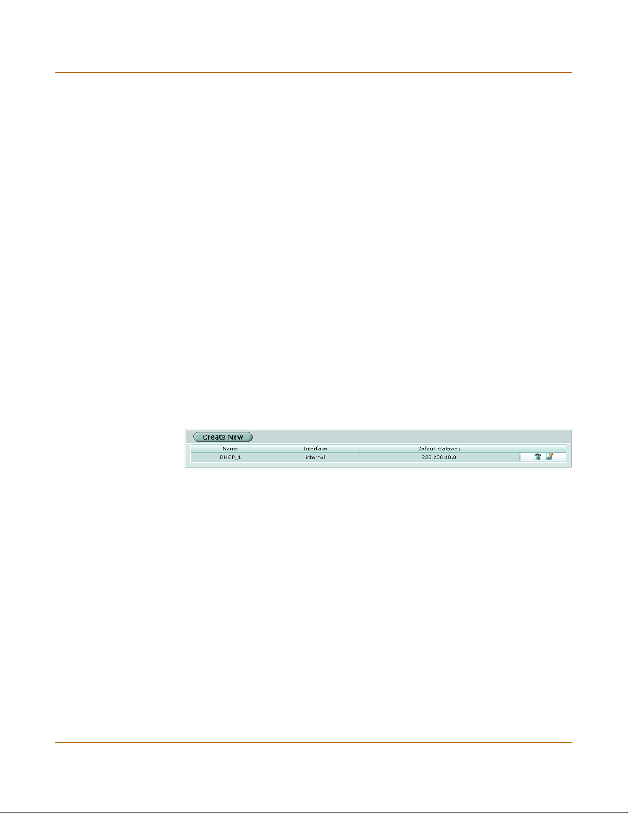
System DHCP DHCP service settings
To configure an interface to be a DHCP server
You can configure a DHCP server for any FortiGate interface. As a DHCP server, the
interface dynamically assigns IP addresses to hosts on the network connected to the
interface. You can also configure a DHCP server for more than one FortiGate
interface.
1 Go to System > DHCP > Service.
2 Select Edit beside the interface to which you want to add a DHCP server.
3 Select DHCP Server.
4 Select OK.
5 Add a DHCP server configuration for this interface.
See “To configure a DHCP server for an interface” on page 76.
Server
You can configure one or more DHCP servers for any FortiGate interface. As a DHCP
server, the interface dynamically assigns IP addresses to hosts on a network
connected to the interface.
You can add more than one DHCP server to a single interface to be able to provide
DHCP services to multiple networks. For more information, see “To configure multiple
DHCP servers for an interface” on page 77.
Figure 22: DHCP Server list
Create New Add a new DHCP server.
Name Name of the DHCP server.
Interface The interface for which the DHCP server is configured.
Default Gateway The DHCP server configuration default gateway
Delete Delete a DHCP server configuration.
Edit/View icon View or modify a DHCP server configuration.
FortiGate-100A Administration Guide 01-28007-0068-20041203 75
Page 76

DHCP server settings System DHCP
DHCP server settings
Figure 23: Server options
Name Enter a name for the DHCP server configuration.
Interface Select the interface for which to configure the DHCP server.
Domain Enter the domain that the DHCP server assigns to DHCP clients.
Default Gateway Enter the IP address of the default gateway that the DHCP server
IP Range Enter the starting IP and ending IP for the range of IP addresses that this
Network Mask Enter the netmask that the DHCP server assigns to DHCP clients.
Lease Time Select Unlimited for an unlimited lease time or enter the interval in days,
DNS Server Enter the IP addresses of up to 3 DNS servers that the DHCP server
WINS Server Add the IP addresses of one or two WINS servers that the DHCP server
Option Up to three custom DHCP options that can be sent by the DHCP server.
assigns to DHCP clients.
DHCP server assigns to DHCP clients.
hours, and minutes after which a DHCP client must ask the DHCP server
for new settings. The lease time can range from 5 minutes to 100 days.
assigns to DHCP clients.
assigns to DHCP clients.
Code is the DHCP option code in the range 1 to 255. Option is an even
number of hexadecimal characters and is not required for some option
codes. For detailed information about DHCP options, see RFC 2132,
DHCP Options and BOOTP Vendor Extensions.
To configure a DHCP server for an interface
After configuring an interface to be a DHCP server (using the procedure “To configure
an interface to be a DHCP server” on page 75), you must configure a DHCP server for
the interface.
1 Go to System > DHCP > Server.
2 Select Create New.
76 01-28007-0068-20041203 Fortinet Inc.
Page 77

System DHCP DHCP server settings
3 Add a name for the DHCP server.
4 Select the interface
5 Configure the DHCP server.
The IP range must match the subnet address of the network from which the DHCP
request was received. Usually this would be the subnet connected to the interface for
which you are added the DHCP server.
6 Select OK to save the DHCP server configuration.
To configure multiple DHCP servers for an interface
If an interface is connected to a network that includes routers connected to different
subnets, you can:
1 Configure computers on the subnets to get their IP configuration using DHCP.
The IP range of each DHCP server must match the subnet addresses.
2 Configure the routers for DHCP relay.
3 Add multiple DHCP servers to the interface, one for each subnet.
When a computer on one of the connected subnets sends a DHCP request it is
relayed to the FortiGate interface by the router, using DHCP relay. The FortiGate unit
selects the DHCP server configuration with an IP range that matches the subnet
address from which the DHCP request was received and uses this DHCP server to
assign an IP configuration to the computer that made the DHCP request. The DHCP
configuration packets are sent back to the router and the router relays them to the
DHCP client.
Exclude range
Add up to 16 exclude ranges of IP addresses that FortiGate DHCP servers cannot
assign to DHCP clients. Exclude ranges apply to all FortiGate DHCP servers.
Figure 24: Exclude range list
Create New Select Create New to add an exclude range.
# The ID number of each exclude range. ID numbers are assigned
sequentially by the web-based manager. When you add or edit exclude
ranges from the CLI you must specify the ID number.
Starting IP The starting IP of the exclude range.
Ending IP The ending IP of the exclude range.
Delete Delete an exclude range.
Edit/View icon View or modify an exclude range.
FortiGate-100A Administration Guide 01-28007-0068-20041203 77
Page 78

DHCP exclude range settings System DHCP
DHCP exclude range settings
The range cannot exceed 65536 IP addresses.
Figure 25: Exclude range settings
Starting IP Enter the starting IP of an exclude range.
Ending IP Enter the ending IP of an exclude range.
To add an exclusion range
1 Go to System > DHCP > Exclude Range.
2 Select Create New.
3 Add the starting IP and ending IP.
4 Select OK to save the exclusion range.
IP/MAC binding
If you have added DHCP servers, you can use DHCP IP/MAC binding to reserve an
IP address for a particular device on the network according to the MAC address of the
device. When you add the MAC address and an IP address to the IP/MAC binding list,
the DHCP server always assigns this IP address to the MAC address. IP/MAC binding
pairs apply to all FortiGate DHCP servers.
Figure 26: IP/MAC binding list
Create New Select Create New to add a DHCP IP/MAC binding pair.
Name The name for the IP and MAC address pair.
IP Address The IP address for the IP and MAC address pair. The IP address must be
within the configured IP range.
MAC Address The MAC address of the device.
Delete icon. Delete an IP/MAC binding pair.
Edit/View icon. View or modify an IP/MAC binding pair.
78 01-28007-0068-20041203 Fortinet Inc.
Page 79

System DHCP DHCP IP/MAC binding settings
DHCP IP/MAC binding settings
Figure 27: IP/MAC binding options
Name Enter a name for the IP/MAC address pair.
IP Address Enter the IP address for the IP and MAC address pair. The IP address must
MAC Address Enter the MAC address of the device.
To add a DHCP IP/MAC binding pair
1 Go to System > DHCP > IP/MAC Binding.
2 Select Create New.
3 Add a name for the IP/MAC pair.
4 Add the IP address and MAC address.
5 Select OK to save the IP/MAC pair.
be within the configured IP range.
Dynamic IP
You can view the list of IP addresses that the DHCP server has assigned, their
corresponding MAC addresses, and the expiry time and date for these addresses.
Interface Select to display its dynamic IP list.
IP The IP addresses that the DHCP server has assigned.
MAC The corresponding MAC addresses for the dynamic IP addresses.
Expire The expiry time and date for the dynamic IP addresses and their corresponding
MAC addresses.
To view the dynamic IP list
1 Go to System > DHCP > Dynamic IP.
2 Select the interface for which you want to view the list.
FortiGate-100A Administration Guide 01-28007-0068-20041203 79
Page 80

DHCP IP/MAC binding settings System DHCP
80 01-28007-0068-20041203 Fortinet Inc.
Page 81

FortiGate-100A Administration Guide Version 2.80 MR7
System config
Use the System Config page to make any of the following changes to the FortiGate
system configuration:
• System time
• Options
• HA
• SNMP
• Replacement messages
• FortiManager
System time
Go to System > Config > Time to set the FortiGate system time.
For effective scheduling and logging, the FortiGate system time must be accurate.
You can either manually set the FortiGate system time or you can configure the
FortiGate unit to automatically keep its system time correct by synchronizing with a
Network Time Protocol (NTP) server.
Figure 28: System time
System Time The current FortiGate system date and time.
Refresh Select Refresh to update the display of the current FortiGate system date
Time Zone Select the current FortiGate system time zone.
and time.
FortiGate-100A Administration Guide 01-28007-0068-20041203 81
Page 82

System config
Automatically
adjust clock for
daylight saving
changes
Set Time Select Set Time to set the FortiGate system date and time to the correct
Synchronize with
NTP Server
Server Enter the IP address or domain name of the NTP server that the
Syn Interval Specify how often the FortiGate unit should synchronize its time with the
Select the Automatically adjust clock for daylight saving changes check
box if you want the FortiGate system clock to be adjusted automatically
when your time zone changes to daylight saving time and back to
standard time.
date and time.
Select Synchronize with NTP Server to configure the FortiGate unit to
use NTP to automatically set the system date and time. For more
information about NTP and to find the IP address of an NTP server that
you can use, see http://www.ntp.org.
FortiGate unit can use to set its time and date.
NTP server. A typical Syn Interval would be 1440 minutes for the
FortiGate unit to synchronize its time once a day.
To manually set the FortiGate date and time
1 Go to System > Config > Time.
2 Select Refresh to display the current FortiGate system date and time.
3 Select your Time Zone from the list.
4 Optionally, select Automatically adjust clock for daylight saving changes check box.
5 Select Set Time and set the FortiGate system date and time.
6 Set the hour, minute, second, month, day, and year as required.
7 Select Apply.
Options
To use NTP to set the FortiGate date and time
1 Go to System > Config > Time.
2 Select Synchronize with NTP Server to configure the FortiGate unit to use NTP to
automatically set the system time and date.
3 Enter the IP address or domain name of the NTP server that the FortiGate unit can
use to set its time and date.
4 Specify how often the FortiGate unit should synchronize its time with the NTP server.
5 Select Apply.
Go to System > Config > Options to set the following options:
• Timeout settings including the idle timeout and authentication timeout
• The language displayed by the web-based manager
• Dead gateway detection interval and failover detection
82 01-28007-0068-20041203 Fortinet Inc.
Page 83

System config
Figure 29: System config options
Idle Timeout Set the idle time out to control the amount of inactive time before the
Auth Timeout Set the firewall user authentication timeout to control how long an
Language Select a language for the web-based manager to use. Choose from
Detection Interval Set the dead gateway detection failover interval. Enter a number in
Fail-over Detection Set the ping server dead gateway detection failover number. Enter the
administrator must log in again. The maximum admintimeout is 480
minutes (8 hours). To improve security keep the idle timeout at the default
value of 5 minutes.
authenticated connection can be idle before the user must authenticate
again. The maximum authtimeout is 480 minutes (8 hours). The
default Auth Timeout is 15 minutes.
For more information, see “Setting authentication timeout” on page 234.
English, Simplified Chinese, Japanese, Korean, or French.
seconds to specify how often the FortiGate unit pings the target.
number of times that ping fails before the FortiGate unit assumes that the
gateway is no longer functioning.
To set the system idle timeout
1 Go to System > Config > Options.
2 For Idle Timeout, type a number in minutes.
3 Select Apply.
To set the Auth timeout
1 Go to System > Config > Options.
2 For Auth Timeout, type a number in minutes.
3 Select Apply.
To select a language for the web-based manager
1 Go to System > Config > Options.
2 From the Languages list, select a language for the web-based manager to use.
3 Select Apply.
FortiGate-100A Administration Guide 01-28007-0068-20041203 83
Page 84

HA
System config
Note: You should select the language that the management computer operating system uses.
To modify the dead gateway detection settings
Modify dead gateway detection to control how the FortiGate unit confirms connectivity
with a ping server added to an interface configuration. For information about adding a
ping server to an interface, see “To add a ping server to an interface” on page 56.
1 Go to System > Config > Options.
2 For Detection Interval, type a number in seconds to specify how often the FortiGate
unit tests the connection to the ping target.
3 For Fail-over Detection, type a number of times that the connection test fails before
the FortiGate unit assumes that the gateway is no longer functioning.
4 Select Apply.
Fortinet achieves high availability (HA) using redundant hardware and the FortiGate
Clustering Protocol (FGCP). Each FortiGate unit in an HA cluster enforces the same
overall security policy and shares the same configuration settings. You can add up to
32 FortiGate units to an HA cluster. Each FortiGate unit in an HA cluster must be the
same model and must be running the same FortiOS firmware image.
The FortiGate units in the cluster use cluster ethernet interfaces to communicate
cluster session information, synchronize the cluster configuration, synchronize the
cluster routing table, and report individual cluster member status. The units in the
cluster are constantly communicating HA status information to make sure that the
cluster is operating properly. This communication is called the HA heartbeat.
FortiGate HA supports link failover, device failover, and HA heartbeat failover.
Link failover If one of the links to a FortiGate unit in an HA cluster fails, all functions, all
Device failover If one of the FortiGate units in an HA cluster fails, all functions, all established
HA heartbeat
failover
a.HA does not provide session failover for PPPoE, DHCP, PPTP, and L2TP services.
established firewall connections, and all IPSec VPN sessions
by the other FortiGate units in the HA cluster. For information about link
failover, see “Monitor priorities” on page 90.
firewall connections, and all IPSec VPN sessions are maintained by the other
FortiGate units in the HA cluster.
You can configure multiple interfaces to be HA heartbeat devices. If an
interface functioning as an HA heartbeat device fails, the HA heartbeat is
transferred to another interface also configured as an HA heartbeat device.
a
are maintained
FortiGate units can be configured to operate in active-passive (A-P) or active-active
(A-A) HA mode. Active-active and active-passive clusters can run in either NAT/Route
or Transparent mode.
84 01-28007-0068-20041203 Fortinet Inc.
Page 85

System config HA configuration
An active-passive (A-P) HA cluster, also referred to as hot standby HA, consists of a
primary FortiGate unit that processes traffic, and one or more subordinate FortiGate
units. The subordinate FortiGate units are connected to the network and to the
primary FortiGate unit but do not process traffic.
Active-active (A-A) HA load balances network traffic all the FortiGate units in the
cluster. An active-active HA cluster consists of a primary FortiGate unit that processes
traffic and one or more subordinate units that also process traffic. The primary
FortiGate unit uses a load balancing algorithm to distribute virus scanning to all the
FortiGate units in the HA cluster.
By default the FortiGate unit load balances virus scanning among all of the FortiGate
units in the cluster. Using the CLI, you can configure the FortiGate unit to load balance
all network traffic among the FortiGate units in the cluster. See the FortiGate CLI
Reference Guide for more information.
For more information about FortiGate HA and the FGCP, see the FortiGate High
Availability Guide.
HA configuration
Go to System > Config > HA and use the options described below to configure HA.
Figure 30: HA configuration
Standalone Mode
Standalone mode is the default operation mode. If Standalone mode is selected the
FortiGate unit is not operating in HA mode.
Select Standalone Mode if you want to stop a cluster unit from operating in HA mode.
High Availability
Select High Availability to operate the FortiGate unit in HA mode. After selecting High
Availability, complete the remainder of the HA configuration.
FortiGate-100A Administration Guide 01-28007-0068-20041203 85
Page 86

HA configuration System config
Cluster Members
When the cluster is operating, you can select Cluster Members to view the status of all
FortiGate units in the cluster. Status information includes the cluster ID, status, up
time, weight, and monitor information. For more information, see “To view the status of
each cluster member” on page 95.
Mode
All members of the HA cluster must be set to the same HA mode.
Active-Active Load balancing and failover HA. Each cluster unit actively processes
Active-Passive Failover HA. The primary FortiGate unit in the cluster processes all
connections and monitors the status of the other FortiGate units in the cluster.
The primary FortiGate unit in the cluster controls load balancing among all of
the cluster units.
connections. All other FortiGate units in the cluster passively monitor the
cluster status and remain synchronized with the primary FortiGate unit.
Group ID
The group ID range is from 0 to 63. All members of the HA cluster must have the
same group ID.
When the FortiGate units in the cluster are switched to HA mode, all of the interfaces
of all of the units in the cluster acquire the same virtual MAC address. This virtual
MAC address is set according to the group ID. Tab le 3 lists the virtual MAC address
set for each group ID.
Table 3: HA group ID and MAC address
Group ID MAC Address
0 00-09-0f-06-ff-00
1 00-09-0f-06-ff-01
2 00-09-0f-06-ff-02
3 00-09-0f-06-ff-03
… ...
63 00-09-0f-06-ff-3f
If you have more than one HA cluster on the same network, each cluster should have
a different group ID. If two clusters on the same network have the same group ID, the
duplicate MAC addresses cause addressing conflicts on the network.
Unit Priority
Optionally set the unit priority of the cluster unit. Each cluster unit can have a different
unit priority (the unit priority is not synchronized among cluster members). During HA
negotiation, the unit with the highest unit priority becomes the primary cluster unit. The
unit priority range is 0 to 255. The default unit priority is 128.
86 01-28007-0068-20041203 Fortinet Inc.
Page 87

System config HA configuration
You can use the unit priority to control the order in which cluster units become the
primary cluster unit when a cluster unit fails. For example, if you have three
FortiGate-3600s in a cluster you can set the unit priorities as shown in Ta bl e 4 . Cluster
unit A will always be the primary cluster unit because it has the highest priority. If
cluster unit A fails, cluster unit B becomes the primary cluster unit because cluster unit
B has a higher unit priority than cluster unit C.
Table 4: Example unit priorities for a cluster of three cluster units
Cluster unit Unit priority
A200
B100
C50
The unit priority is not synchronized to all cluster units. Each cluster unit can have a
different unit priority.
In a functioning cluster, if you change the unit priority of the current primary cluster
unit to a lower priority, when the cluster renegotiates a different cluster unit becomes
the primary cluster unit.
Override Master
Configure a cluster unit to always override the current primary cluster unit and become
the primary cluster unit. Enable override master for the cluster unit that you have given
the highest unit priority. Enabling Override Master means that this cluster unit always
becomes the primary cluster unit.
In a typical FortiGate cluster configuration, the primary unit is selected automatically.
In some situations, you might want to control which unit becomes the primary unit.
You can configure a FortiGate unit as the permanent primary unit by setting a high
unit priority and by selecting override master. With this configuration, the same cluster
unit always becomes the primary cluster unit.
If override master is enabled and the primary cluster unit fails another cluster unit
becomes the primary unit. When the cluster unit with override master enabled rejoins
the cluster it overrides the current primary unit and becomes the new primary unit.
When this override occurs, all communication sessions through the cluster are lost
and must be re-established.
Override master is not synchronized to all cluster units.
In a functioning cluster, if you select override master for a cluster unit the cluster
negotiates and may select a new primary cluster unit.
Password
Enter a password for the HA cluster. The password must be the same for all FortiGate
units in the HA cluster. The maximum password length is 15 characters.
If you have more than one FortiGate HA cluster on the same network, each cluster
should have a different password.
FortiGate-100A Administration Guide 01-28007-0068-20041203 87
Page 88

HA configuration System config
Schedule
If you are configuring an active-active cluster, select a load balancing schedule.
None No load balancing. Select None when the cluster interfaces are connected
Hub Load balancing if the cluster interfaces are connected to a hub. Traffic is
Least-
Connection
Round-Robin Round robin load balancing. If the cluster units are connected using
Weighted
Round-Robin
Random Random load balancing. If the cluster units are connected using switches,
IP Load balancing according to IP address. If the cluster units are connected
IP Port Load balancing according to IP address and port. If the cluster units are
to load balancing switches.
distributed to cluster units based on the Source IP and Destination IP of the
packet.
Least connection load balancing. If the cluster units are connected using
switches, select Least Connection to distribute network traffic to the cluster
unit currently processing the fewest connections.
switches, select Round-Robin to distribute network traffic to the next
available cluster unit.
Weighted round robin load balancing. Similar to round robin, but weighted
values are assigned to each of the units in a cluster based on their capacity
and on how many connections they are currently processing. For example,
the primary unit should have a lower weighted value because it handles
scheduling and forwards traffic. Weighted round robin distributes traffic more
evenly because units that are not processing traffic will be more likely to
receive new connections than units that are very busy.
select Random to randomly distribute traffic to cluster units.
using switches, select IP to distribute traffic to units in a cluster based on the
Source IP and Destination IP of the packet.
connected using switches, select IP Port to distribute traffic to units in a
cluster based on the source IP, source port, destination IP, and destination
port of the packet.
Priorities of Heartbeat Device
Enable or disable HA heartbeat communication and set the heartbeat priority for each
interface in the cluster.
By default HA heartbeat communication is set for two interfaces. You can disable HA
heartbeat communication for either of these interfaces or enable HA heartbeat for
other interfaces. In most cases you can maintain the default heartbeat device
configuration as long as you can connect the heartbeat device interfaces together.
To enable HA heartbeat communication for an interface, enter a priority for the
interface. To disable HA heartbeat communication for an interface, delete the priority
for the interface.
The HA heartbeat priority range is 0 to 512. The interface with the highest priority
handles all HA heartbeat traffic. If this interface fails or becomes disconnected, the
interface with the next highest priority handles all HA heartbeat traffic.
The cluster units use the ethernet interfaces configured with HA heartbeat priorities for
HA heartbeat communication. The HA heartbeat communicates cluster session
information, synchronizes the cluster configuration, synchronizes the cluster routing
table, and reports individual cluster member status. The HA heartbeat constantly
communicates HA status information to make sure that the cluster is operating
properly.
88 01-28007-0068-20041203 Fortinet Inc.
Page 89

System config HA configuration
You can enable heartbeat communications for physical interfaces, but not for VLAN
subinterfaces.
Enabling the HA heartbeat for more interfaces increases reliability. If an interface fails,
the HA heartbeat can be diverted to another interface.
HA heartbeat traffic can use a considerable amount of network bandwidth. If possible,
enable HA heartbeat traffic on interfaces only used for HA heartbeat traffic or on
interfaces connected to less busy networks.
Table 5: Default heartbeat device configuration
FortiGate model Default heartbeat device Default priority
FortiGate-100A External 50
DMZ 2 100
Change the heartbeat device priorities as required to control the interface that is used
for heartbeat traffic and the interface to which heartbeat traffic reverts if the interface
with the highest heartbeat priority fails or is disconnected.
Setting the heartbeat priority for more interfaces increases the reliability of the cluster.
To optimize bandwidth use, you can route most heartbeat traffic to interfaces that
handle less network traffic. You can also create a failover path by setting heartbeat
priorities so that you can control the order in which interfaces are used for heartbeat
traffic.
The heartbeat priority must be set for at least one cluster interface. If heartbeat
communication is interrupted the cluster stops processing traffic.
Heartbeat device IP addresses
You do not need to assign IP addresses to the heartbeat device interfaces for them to
be able to process heartbeat packets. In HA mode the cluster assigns virtual IP
addresses to the heartbeat device interfaces. The primary cluster unit heartbeat
device interface is assigned the IP address 10.0.0.1 and the subordinate unit is
assigned the IP address 10.0.0.2. A third cluster unit would be assigned the IP
address 10.0.0.3 and so on.
For best results, isolate each heartbeat device on its own network. Heartbeat packets
contain sensitive information about the cluster configuration. Also, heartbeat packets
may use a considerable amount of network bandwidth and it is preferable to isolate
this traffic from your user networks. The extra bandwidth used by heartbeat packets
could also reduce the capacity of the interface to process network traffic.
For most FortiGate models if you do not change the heartbeat device configuration,
you would isolate the HA interfaces of all of the cluster units by connecting them all to
the same switch. If the cluster consists of two FortiGate units you can connect the
heartbeat device interfaces directly using a crossover cable.
HA heartbeat and data traffic are supported on the same FortiGate interface. In
NAT/Route mode, if you decide to use the heartbeat device interfaces for processing
network traffic or for a management connection, you can assign the interface any IP
address. This IP address does not affect the heartbeat traffic. In Transparent mode,
you can connect the interface to your network.
FortiGate-100A Administration Guide 01-28007-0068-20041203 89
Page 90

Configuring an HA cluster System config
Monitor priorities
Monitor priorities and link failover is not supported for the internal interface.
Enable or disable monitoring a FortiGate interface to verify that the interface is
functioning properly and connected to its network. If a monitored interface fails or is
disconnected from its network the interface leaves the cluster. The cluster reroutes
the traffic being processed by that interface to the same interface of another cluster
unit in the cluster that still has a connection to the network. This other cluster unit
becomes the new primary cluster unit.
If you can re-establish traffic flow through the interface (for example, if you re-connect
a disconnected network cable) the interface rejoins the cluster. If Override Master is
enabled for this FortiGate unit (see “Override Master” on page 87), this FortiGate unit
becomes the primary unit in the cluster again.
Note: Only monitor interfaces that are connected to networks.
Note: You can monitor physical interfaces, but not VLAN subinterfaces.
Increase the priority of interfaces connected to higher priority networks or networks
with more traffic. The monitor priority range is 0 to 512.
If a high priority interface on the primary cluster unit fails, one of the other units in the
cluster becomes the new primary unit to provide better service to the high priority
network.
If a low priority interface fails on one cluster unit and a high priority interface fails on
another cluster unit, a unit in the cluster with a working connection to the high priority
interface would, if it becomes necessary to negotiate a new primary unit, be selected
instead of a unit with a working connection to the low priority interface.
Configuring an HA cluster
Use the following procedures to create an HA cluster consisting of two or more
FortiGate units. These procedures describe how to configure each of the FortiGate
units for HA operation and then how to connect the FortiGate units to form a cluster.
Once the cluster is connected you can configure it in the same way as you would
configure a standalone FortiGate unit.
To configure a FortiGate unit for HA operation
Each FortiGate unit in the cluster must have the same HA configuration. Use the
following procedure to configure each FortiGate unit for HA operation.
Note: The following procedure does not include steps for configuring interface heartbeat
devices and interface monitoring. Both of these HA settings should be configured after the
cluster is up and running.
90 01-28007-0068-20041203 Fortinet Inc.
Page 91

System config Configuring an HA cluster
Note: The following procedure does not include steps for configuring interface heartbeat
devices and interface monitoring. Interface monitoring should be configured after the cluster is
up and running.
1 Power on the FortiGate unit to be configured.
2 Connect to the web-based manager.
3 Give the FortiGate unit a unique host name.
See “To change FortiGate host name” on page 30. Use host names to identify
individual cluster units.
4 Go to System > Config > HA.
5 Select HA.
6 Select the HA mode.
7 Select a Group ID for the cluster.
The Group ID must be the same for all FortiGate units in the HA cluster.
8 Optionally change the Unit Priority.
See “Unit Priority” on page 86.
9 If required, select Override master.
See “Override Master” on page 87.
10 Enter and confirm a password for the HA cluster.
11 If you are configuring Active-Active HA, select a schedule.
See “Schedule” on page 88.
12 Select Apply.
The FortiGate unit negotiates to establish an HA cluster. When you select apply you
may temporarily lose connectivity with the FortiGate unit as the HA cluster negotiates.
13 If you are configuring a NAT/Route mode cluster, power off the FortiGate unit and
then repeat this procedure for all the FortiGate units in the cluster. Once all of the units
are configured, continue with “To connect a FortiGate HA cluster” on page 92.
14 If you are configuring a Transparent mode cluster, reconnect to the web-based
manager.
You may have to wait a few minutes before you can reconnect.
15 Go to System > Status.
16 Select Change to Transparent Mode and select OK to switch the FortiGate unit to
Transparent mode.
17 Power off the FortiGate unit.
18 Repeat this procedure for all of the FortiGate units in the cluster then continue with “To
connect a FortiGate HA cluster” on page 92.
FortiGate-100A Administration Guide 01-28007-0068-20041203 91
Page 92

Configuring an HA cluster System config
To connect a FortiGate HA cluster
Use the following procedure to connect a cluster operating in NAT/Route mode or
Transparent mode. Connect the FortiGate units in the cluster to each other and to
your network. You must connect all matching interfaces in the cluster to the same hub
or switch. Then you must connect these interfaces to their networks using the same
hub or switch.
Fortinet recommends using switches for all cluster connections for the best
performance.
The FortiGate units in the cluster use cluster ethernet interfaces to communicate
cluster session information, synchronize the cluster configuration, and report
individual cluster member status. The units in the cluster are constantly
communicating HA status information to make sure that the cluster is operating
properly. This cluster communication is also called the cluster heartbeat.
Inserting an HA cluster into your network temporarily interrupts communications on
the network because new physical connections are being made to route traffic through
the cluster. Also, starting the cluster interrupts network traffic until the individual
FortiGate units in the cluster are functioning and the cluster completes negotiation.
Cluster negotiation normally takes just a few seconds. During system startup and
negotiation all network traffic is dropped.
1 Connect the cluster units.
• Connect the internal interfaces of each FortiGate unit to a switch or hub connected
to your internal network.
• Connect the WAN1 interfaces of each FortiGate unit to a switch or hub connected
to your external network.
• Connect the DMZ2 interfaces of the FortiGate units to the same switch or hub. By
default the DMZ2 interfaces are used for HA heartbeat communication. These
interfaces should be connected together for the HA cluster to function.
• Optionally connect the WAN2 interfaces of each FortiGate unit to a switch or hub
connected a second external network.
• Optionally Connect the DMZ1 interfaces of the FortiGate units to another switch or
hub.
92 01-28007-0068-20041203 Fortinet Inc.
Page 93

System config Configuring an HA cluster
Figure 31: HA network configuration
Internet
Hub or
Switch
WAN1
WAN 1 WAN 2
PWR STATUS
LINK 100 LINK 100 LINK 100 LINK 100 LINK 100 LINK 100 LINK 100 LINK 100
A
DMZ 1
DMZ 2
DMZ 2
Internal
INTERNAL
4321
Hub or
Switch
DMZ 2
WAN 1 WAN 2
PWR STATUS
LINK 100 LINK 100 LINK 100 LINK 100 LINK 100 LINK 100 LINK 100 LINK 100
A
WAN1
INTERNAL
DMZ 1
DMZ 2
4321
Internal
Router
Internal Network
2 Power on all the FortiGate units in the cluster.
As the units start, they negotiate to choose the primary cluster unit and the
subordinate units. This negotiation occurs with no user intervention and normally just
takes a few seconds.
You can now configure the cluster as if it is a single FortiGate unit.
To add a new unit to a functioning cluster
1 Configure the new FortiGate unit for HA operation with the same HA configuration as
the other units in the cluster.
2 If the cluster is running in Transparent mode, change the operating mode of the new
FortiGate unit to Transparent mode.
3 Connect the new FortiGate unit to the cluster.
4 Power on the new FortiGate unit.
When the unit starts it negotiates to join the cluster. After it joins the cluster, the cluster
synchronizes the new unit configuration with the configuration of the primary unit.
FortiGate-100A Administration Guide 01-28007-0068-20041203 93
Page 94

Managing an HA cluster System config
To configure weighted-round-robin weights
By default, in active-active HA mode the weighted round-robin schedule assigns the
same weight to each FortiGate unit in the cluster. If you configure a cluster to use the
weighted round-robin schedule, from the CLI you can use config system ha
weight to configure a weight value for each cluster unit. The weight value sets the
maximum number of connections that are sent to a cluster unit before a connection
can be sent to the next cluster unit. You can set weight values to control the number of
connections processed by each cluster unit. For example, you might want to reduce
the number of connections processed by the primary cluster unit by increasing the
weight assigned to the subordinate cluster units.
Weight values are entered as two values; the priority order of the unit in the cluster (in
the range 0 to 31) followed by its weight (also in the range 0 to 31). For example, if you
have a cluster of three FortiGate units, you can enter the following command to
configure the weight values for each unit:
config system ha
set ha weight 0 1 1 3 2 3
end
This command has the following results:
• The first connection is processed by the primary unit (priority 0, weight 1)
• The next three connections are processed by the first subordinate unit (priority 1,
weight 3)
• The next three connections are processed by the second subordinate unit (priority
2, weight 3)
The subordinate units process more connections than the primary unit, and both
subordinate units, on average, process the same number of connections.
Managing an HA cluster
The configurations of all of the FortiGate units in the cluster are synchronized so that
the FortiGate units can function as a cluster. Because of this synchronization, you
manage the HA cluster instead of managing the individual FortiGate units in the
cluster. You manage the cluster by connecting to the web-based manager using any
cluster interface configured for HTTPS administrative access. You can also manage
the cluster by connecting to the CLI using any cluster interface configured for SSH
administrative access.
You can also use SNMP to manage the cluster by configuring a cluster interface for
SNMP administrative access. Using an SNMP manager you can get cluster
configuration information and receive traps. For a list of HA MIB fields, see “HA MIB
fields” on page 104 and “FortiGate HA traps” on page 103.
You can change the cluster configuration by connecting to the cluster and changing
the configuration of the primary FortiGate unit. The cluster automatically synchronizes
all configuration changes to the subordinate units in the cluster as the changes are
made.
The only configuration change that is not synchronized is the FortiGate host name.
You can give each cluster unit a unique host name to help to identify cluster members.
94 01-28007-0068-20041203 Fortinet Inc.
Page 95

System config Managing an HA cluster
You can use the web-based manager to monitor the status and logs of individual
cluster members. See “To view the status of each cluster member” on page 95 and “To
view and manage logs for individual cluster units” on page 96.
You can manage individual cluster units by using SSH to connect to the CLI of the
cluster. From the CLI you can use the execute ha manage command to connect to
the CLI of each unit in the cluster. You can also manage individual cluster units by
using a null-modem cable to connect to the primary cluster unit. From there you can
also use the execute ha manage command to connect to the CLI of each unit in the
cluster. See “To manage individual cluster units” on page 97 for more information.
To view the status of each cluster member
1 Connect to the cluster and log into the web-based manager.
2 Go to System > Config > HA.
3 Select Cluster Members.
A list of cluster members appears. The list includes the cluster ID of each cluster
member as well as status information for each cluster member.
Figure 32: Example cluster members list (active-active cluster)
Refresh every Select to control how often the web-based manager updates the system
Go Select to set the selected refresh interval.
Back to HA
configuration page
Cluster ID Use the cluster ID to identify each FortiGate unit in the cluster. The
Status Indicates the status of each cluster unit. A green check mark indicates
Up Time The time in days, hours, minutes, and seconds since the cluster unit was
Monitor Displays system status information for each cluster unit.
FortiGate-100A Administration Guide 01-28007-0068-20041203 95
status display.
Close the cluster members list and return to the HA configuration page.
cluster ID matches the FortiGate unit serial number.
that the cluster unit is operating normally. A red X indicates that the
cluster unit cannot communicate with the primary unit.
last started.
Page 96

Managing an HA cluster System config
CPU Usage The current CPU status of each cluster unit. The web-based manager
Memory Usage The current memory status of each cluster unit. The web-based manager
Active Sessions The number of communications sessions being processed by the each
Total Packets The number of packets that have been processed by the cluster unit
Virus Detected The number of viruses detected by the cluster unit.
Network Utilization The total network bandwidth being used by all of the cluster unit
Total Bytes The number of bytes that have been processed by the cluster unit since it
Intrusion Detected The number of intrusions or attacks detected by the cluster unit.
displays CPU usage for core processes only. CPU usage for
management processes (for example, for HTTPS connections to the
web-based manager) is excluded.
displays memory usage for core processes only. Memory usage for
management processes (for example, for HTTPS connections to the
web-based manager) is excluded.
cluster unit.
since it last started up.
interfaces.
last started up.
To view and manage logs for individual cluster units
1 Connect to the cluster and log into the web-based manager.
2 Go to Log&Report > Log Access.
The Traffic log, Event log, Attack log, Antivirus log, Web Filter log, and Email Filter log
for the primary unit are displayed.
The HA Cluster pull-down list displays the serial number of the FortiGate unit for which
logs are displayed.
3 Select the serial number of one of the FortiGate units in the cluster to display the logs
for that FortiGate unit.
You can view, search and manage logs saved to memory or logs saved to the hard
disk, depending on the configuration of the cluster unit.
To monitor cluster units for failover
If the primary unit in the cluster fails, the units in the cluster renegotiate to select a new
primary unit. Failure of the primary unit results in the following:
• If SNMP is enabled, the new primary FortiGate unit sends the trap message “HA
switch”. This trap indicates that the primary unit in an HA cluster has failed and has
been replaced with a new primary unit.
• The cluster contains fewer FortiGate units. The failed primary unit no longer
appears on the Cluster Members list.
• The host name and serial number of the primary cluster unit changes.
• The new primary unit logs the following messages to the event log:
HA slave became master
Detected HA member dead
96 01-28007-0068-20041203 Fortinet Inc.
Page 97

System config Managing an HA cluster
If a subordinate unit fails, the cluster continues to function normally. Failure of a
subordinate unit results in the following:
• The cluster contains fewer FortiGate units. The failed unit no longer appears on the
Cluster Members list.
• The master unit logs the following message to the event log:
Detected HA member dead
To manage individual cluster units
This procedure describes how to log into the primary unit CLI and from there to
connect to the CLI of subordinate cluster units. You log into the subordinate unit using
the ha_admin administrator account. This built-in administrator account gives you
read and write permission on the subordinate unit.
1 Use SSH to connect to the cluster and log into the CLI.
Connect to any cluster interface configured for SSH administrative access to log into
the cluster.
You can also use a direct cable connection to log into the primary unit CLI. To do this
you must know which unit is the primary unit.
2 Enter the following command followed by a space and type a question mark (?):
execute ha manage
The CLI displays a list of all the subordinate units in the cluster. Each cluster unit is
numbered, starting at 1. The information displayed for each cluster unit includes the
unit serial number and the host name of the unit.
SNMP
3 Complete the command with the number of the subordinate unit to log into. For
example, to log into subordinate unit 1, enter the following command:
execute ha manage 1
Press Enter to connect to and log into the CLI of the selected subordinate unit. If this
subordinate unit has a different host name, the CLI prompt changes to this host name.
You can use CLI commands to manage this subordinate unit.
4 Enter the following command to return to the primary unit CLI:
exit
You can use the execute ha manage command to log into the CLI of any of the
other subordinate units in the cluster.
You can configure the FortiGate SNMP agent to report system information and send
traps (alarms or event messages) to SNMP managers. Using an SNMP manager, you
can access SNMP traps and data from any FortiGate interface or VLAN subinterface
configured for SNMP management access.
The FortiGate SNMP implementation is read-only. SNMP v1 and v2c compliant SNMP
managers have read-only access to FortiGate system information and can receive
FortiGate traps. To monitor FortiGate system information and receive FortiGate traps
you must compile Fortinet proprietary MIBs as well as Fortinet-supported standard
MIBs into your SNMP manager.
FortiGate-100A Administration Guide 01-28007-0068-20041203 97
Page 98

Configuring SNMP System config
RFC support includes support for most of RFC 2665 (Ethernet-like MIB) and most of
RFC 1213 (MIB II) (for more information, see “FortiGate MIBs” on page 101).
This section describes:
• Configuring SNMP
• SNMP community
• FortiGate MIBs
• FortiGate traps
• Fortinet MIB fields
Configuring SNMP
Go to System > Config > SNMP v1/v2c to configure the SNMP agent.
Figure 33: Configuring SNMP
SNMP Agent Enable the FortiGate SNMP agent.
Description Enter descriptive information about the FortiGate unit. The description
Location Enter the physical location of the FortiGate unit. The system location
Contact Enter the contact information for the person responsible for this FortiGate
Apply Save changes made to the description, location, and contact information.
Create New Select Create New to add a new SNMP community.
Communities The list of SNMP communities added to the FortiGate configuration. You
Name The name of the SNMP community.
Queries The status of SNMP queries for each SNMP community. The query
Traps The status of SNMP traps for each SNMP community. The trap status
Enable Select Enable to activate an SNMP community.
Delete icon Select Delete to remove an SNMP community.
Edit/View icon View or modify an SNMP community.
can be up to 35 characters long.
description can be up to 35 characters long.
unit. The contact information can be up to 35 characters long.
can add up to 3 communities.
status can be enabled or disabled.
can be enabled or disabled.
98 01-28007-0068-20041203 Fortinet Inc.
Page 99

System config SNMP community
SNMP community
An SNMP community is a grouping of equipment for network administration purposes.
Add SNMP communities so that SNMP managers can connect to the FortiGate unit to
view system information and receive SNMP traps. You can add up to three SNMP
communities. Each community can have a different configuration for SNMP queries
and traps. Each community can be configured to monitor the FortiGate unit for a
different set of events. You can also add the IP addresses of up to 8 SNMP managers
to each community.
Figure 34: SNMP community options (part 1)
Figure 35: SNMP community options (part 2)
Community Name Enter a name to identify the SNMP community.
Hosts Identify the SNMP managers that can use the settings in this SNMP
FortiGate-100A Administration Guide 01-28007-0068-20041203 99
community to monitor the FortiGate unit.
Page 100

SNMP community System config
IP Address The IP address of an SNMP manager than can use the settings in this
Interface Optionally select the name of the interface that this SNMP manager uses
Add Select Add to add more SNMP managers. You can add up to 8 SNMP
Queries Enter the Port number (161 by default) that the SNMP managers in this
Traps Enter the Local and Remote port numbers (162 by default) that the
SNMP Event Enable each SNMP event for which the FortiGate unit should send traps
SNMP community to monitor the FortiGate unit. You can also set the IP
address to 0.0.0.0 to so that any SNMP manager can use this SNMP
community.
to connect to the FortiGate unit. You only have to select the interface if
the SNMP manager is not on the same subnet as the FortiGate unit. This
can occur if the SNMP manager is on the Internet or behind a router.
managers to a single community. Select the Delete icon to remove an
SNMP manager.
community use for SNMP v1 and SNMP v2c queries to receive
configuration information from the FortiGate unit. Select the Enable
check box to activate queries for each SNMP version.
FortiGate unit uses to send SNMP v1 and SNMP v2c traps to the SNMP
managers in this community. Select the Enable check box to activate
traps for each SNMP version.
to the SNMP managers in this community.
To configure SNMP access to an interface in NAT/Route mode
Before a remote SNMP manager can connect to the FortiGate agent, you must
configure one or more FortiGate interfaces to accept SNMP connections. See “To
control administrative access to an interface” on page 57.
1 Go to System > Network > Interface.
2 Choose an interface that an SNMP manager connects to and select Edit.
3 For Administrative Access, select SNMP.
4 Select OK.
To configure SNMP access to an interface in Transparent mode
Before a remote SNMP manager can connect to the FortiGate agent, you must
configure one or more FortiGate interfaces to accept SNMP connections. See “To
configure the management interface” on page 60.
1 Go to System > Network > Management.
2 Choose an interface that the SNMP manager connects to and select SNMP.
3 Select Apply.
To enable SNMP and configure basic SNMP settings
1 Go to System > Config > SNMP v1/v2c.
2 Select the Enable check box to enable the FortiGate SNMP Agent.
3 Configure the following SNMP settings: Description, Location, and Contact.
4 Select Apply.
5 Add one or more SNMP communities.
100 01-28007-0068-20041203 Fortinet Inc.
 Loading...