

Page 1
© Copyright 2009 Fortinet Incorporated. All rights reserved.
Products mentioned in this document are trademarks or registered trademarks
of their respective holders.
Regulatory Compliance
FCC Class B Part 15 CSA/CUS
22 July 2009
Visit these links for more information and documentation for your Fortinet product.
• Technical Documentation - http://docs.fortinet.com
• Knowledge Center - http://kb.fortinet.com
• Technical Support - http://support.fortinet.com
• Training Services - http://campus.training.fortinet.com
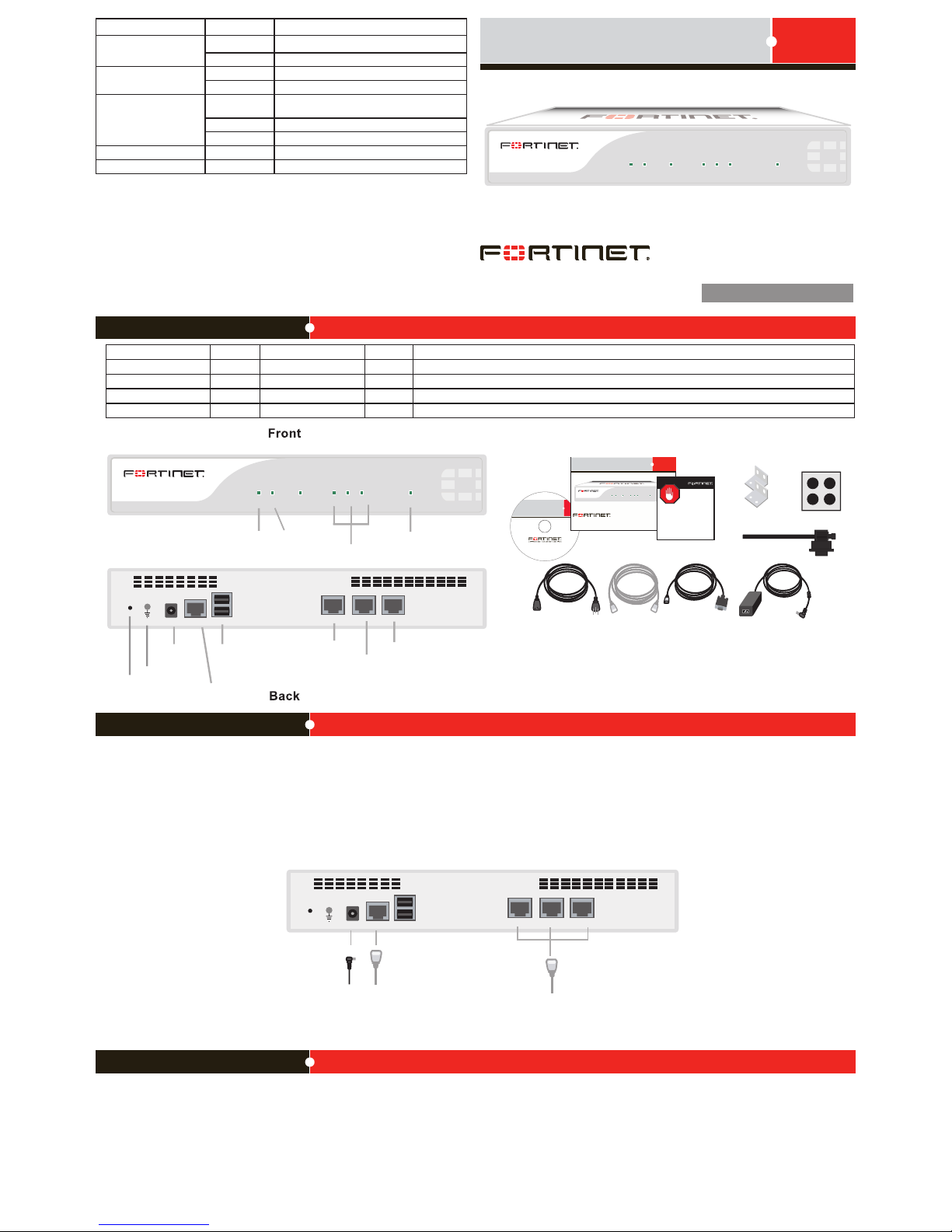
FortiAnalyzer 100C
POWER STATUS ALARM PORT1 PORT2 PORT3 HDD
Connecting
CONSOLE
PORT2 PORT1PORT3
USBDC+12V
FortiAnalyzer 100C
POWER STATUS ALARM PORT1 PORT2 PORT3 HDD
Power
LED
Statu s
LED
Power
Conne ction
RJ-45 Serial
Connection
USB
PORT2
PORT1
PORT3
Hard disk
drive LED
Inter face
Statu s LEDs
Cable Tie
mounting
hole
Ground
CONSOLE
PORT2 PORT1PORT3
USBDC+12V
Power cable
connects to
power supply
Serial cable
connects to serial
port on management computer
Straight-through
Ethernet cable
connects to Internet
Straig ht-through
Ethern et cable
AC Pow er Cable
RJ-45 to
DB-9 S erial Cable
FortiGate-30 B
Tools and Documenation
Copyright 2009 F ortinet Inc orporated. All rights res erved.
Trademarks
QuickStar t Guide
Cable Ti e
Power Supply (12V )
FortiAnalyzer 100C
POWERSTATUS ALARM PORT1PORT2 PORT3 HDD
REGISTER
Rack-M ount
Bracke ts
4 Rubb er feet
Interface Type Speed Protocol Description
Console RJ-45 Ethernet Connection to the management computer. Provides access to the command line interface (CLI).
PORT1 and PORT2 RJ-45 10/100/1000 Base-T Ethernet Connection to the network.
PORT3 RJ-45 10/100 Base-T Ethernet Connection to the network. The speed cannot be changed.
USB USB USB Two optional connections for the USB key, modem, or backup operation.
Package Contents
FortiAnalyzer-100C
05-40001-101293-20090722
QuickStart Guide
Conguration Tools
Connect the following to the FortiAnalyzer unit. Ensure the FortiAnalyzer unit is placed on a stable surface.
• Connect the RJ-45 to DB-9 serial cable into the Console port on the unit. Insert the other end into the management computer.
• Insert the ethernet cable into WAN1. Insert the other end to the router connected to the Internet, or to the modem.
• Connect the AC power cable to the Power Supply shipped with this product.
• Connect the AC power cable to a surge protected power bar or power supply.
• Insert the pointed end of the cable tie into the hole in the rear panel of the chassis to anchor the cable tie to the chassis.
• Loop the loose end around the adapter cable and insert the loose end into the locking latch.
• Pull the loose end to adjust the tightness of the loop around the adapter cable to prevent cable from being accidentally pulled out the unit.
Web-based manager
The FortiAnalyzer web-based manager is an easy to use management tool.
Use it to congure the administrator password, the interface and default gateway addresses,
and the DNS server addresses, add devices for log collection and congure reports.
Requirements:
• An Ethernet connection between the FortiAnalyzer unit and management computer.
• A web browser such as FireFox or Internet Explorer on the management computer.
Command Line Interface (CLI)
The CLI is a full-featured management tool. Use it to congure the administrator password,
the interface addresses, the default gateway address, and the DNS server addresses. To
congure advanced settings, see the Tools and Documentation CD-ROM.
Requirements:
• The RJ-45 to DB-9 serial connection between the FortiAnalyzer unit and the
management computer.
• A terminal emulation application (HyperTerminal for Windows) on the management
computer.
LED State Description
Power
Green The unit is on.
Off The unit is off.
Status
Flashing Green The unit is starting up.
Green The unit is running normally.
Port1, Port2, Port3*
Green The correct cable is in use and the connected
equipment has power.
Flashing green Network activity at this interface.
Off No link established.
Alarm Off Not in use.
HDD Flashing green The internal hard drive is in use.
*Port 3 LED is always green independant of the state.
Page 2

Collecting Information
Conguring
Fortinet Training Services provides classes that orient you quickly to your new equipment, and certications to verify your knowledge level. Fortinet provides a variety of training programs to serve the needs of our customers and partners world-wide.
To learn about the training services that Fortinet provides, visit the Fortinet Training Services web site at http://campus.training.fortinet.com.
Training Services
Port 1
IP: ____ . ____ . ____ . ____
Netmask: ____ . ____ . ____ . ____
Management Access:
Port 2
IP: ____ . ____ . ____ . ____
Netmask: ____ . ____ . ____ . ____
Management Access:
Port 3
IP: ____ . ____ . ____ . ____
Netmask: ____ . ____ . ____ . ____
Management Access:
Factory default settings
Administrator Account
User name: admin
Password: (none)
Port 1
IP: 192.168.1.99
Netmask: 255.255.255.0
Management Access: ping, https, http, ssh
Port 2
IP: 192.168.2.99
Netmask: 255.255.255.0
Management Access: ping, https, http, ssh
Port 3
IP: 192.168.3.99
Netmask: 255.255.255.0
Management Access: ping, https, http, ssh
To reset the FortiAnalyzer unit to the factory defaults, in the CLI type the command
execute factory reset
Web-based Manager
Use the following procedure to connect to the web-based manager for the rst time.
Conguration changes made with the web-based manager are effective immediately without
resetting the FortiAnalyzer unit or interrupting service.
To connect to the web-based manager
1. Connect the Port 1 interface of the FortiAnalyzer unit to Ethernet port of the management computer.
Use a cross-over Ethernet cable to connect the devices directly. Use straight-through
Ethernet cables to connect the devices through a hub or switch.
2. Congure the management computer to be on the same subnet as the FortiAnalyzer
Port 1 interface.
To do this, change the IP address of the management computer to 192.168.1.2 and the
netmask to 255.255.255.0.
3. To access the FortiAnalyzer web-based manager, in your browser, go to
https://192.168.1.99 (remember to include the “s” in https://).
4. Type admin in the Name eld and select Login.
After connecting to the Web-based manager, you can congure the FortiAnalyzer unit IP
address, DNS server IP address, and default gateway to connect the FortiAnalyzer unit to the
network.
To congure interfaces
1. Go to System > Network > Interface.
2. Select the edit icon for each interface to congure.
3. Set the IP address and netmask for the interface.
4. Select OK.
To congure the Primary and Secondary DNS server IP addresses
1. Go to System > Network > DNS, enter the Primary and Secondary DNS IP addresses
select Apply.
To congure a Default Gateway
1. Go to System > Network > Routing and select Create New.
2. Set Gateway to the Default Gateway IP address and select OK.
Command Line Interface
The FortiAnalyzer unit has serial port. Use the null modem cable to connect it to your management computer.
To connect to the FortiAnalyzer unit
1. Use a RJ-45 to DB-9 cable to connect the FortiAnalyzer serial port to the management
computer serial port.
2. Start a terminal emulation program (such as HyperTerminal) on the management computer. Use these settings: Baud Rate 9600, Data bits 8, Parity None, Stop bits 1, Flow
Control None.
3. At the login: prompt, type admin and press Enter twice.
(The login prompt is preceded by the server default host name.)
After connecting to the CLI, you can congure the FortiAnalyzer unit IP address, DNS server
IP address, and default gateway to connect the FortiAnalyzer unit to the network.
To congure the FortiAnalyzer unit using the CLI
1. Set the IP address and netmask of the Port1 interface.
cong system interface
edit port1
set ip <intf_ip>/<netmask_ip>
end
2. Congure the primary and secondary DNS server IP addresses.
cong system dns
set primary <dns-server_ip>
set secondary <dns-server_ip>
end
3. Congure the default gateway.
cong system route
edit 1
set device <interface>
set dst <destination_ip>
set gateway <gateway_ip>
end
Adding an administration password
By default, the admin user does not have a password. To restrict access to the FortiAnalyzer
unit management account, add password for the admin user account.
To add the admin user account password
1. Go to System > Admin.
2. For the admin user, select the Change Password icon.
3. Enter a new password in the New Password box.
4. Reenter the password to Conrm Password box.
5. Select OK.
Shutting down the FortiAnalyzer unit
When powering off the FortiAnalyzer unit, always shut down the unit using the following procedures before disconnecting the power supply. Not following this procedure can increase
the risk of damaging the FortiAnalyzer hard disk.
To power off the FortiAnalyzer unit
1. Go to System > Dashboard.
2. In the System Operation list, select Shut Down.
3. Once the indicates the shut down procedure has completed, disconnect the
FortiAnalyzer unit from the power source.
Shutting down the FortiAnalyzer unit using the CLI
Enter the following command at the prompt:
execute shutdown
 Loading...