

Page 1
FortiSwitch-5003A and 5003
Fabric and Base Backplane Communications Guide
FortiSwitch-5003A
ETH
O
MANAGEMENT
RS232ZRE0
SYSTEM
CONSOLE
ZRE
1
ZRE
2
E1
E0
1514
1312
1110
9876543210
OKCLK
INTEXT
FLT
HOT SWAP
ZRE
RESET
FLT
LED MODE
FortiSwitch-5003
This FortiSwitch-5003A and 5003 Fabric and Base Backplane Communications Guide describes using the
FortiSwitch-5003A board and FortiSwitch-5003 board for FortiGate-5000 series base and fabric backplane switching.
This document also contains the FortiSwitch-5003A CLI reference.
The most recent versions of this and all FortiGate-5000 series documents are available from the FortiGate-5000 page of
the Fortinet Technical Documentation web site (http://docs.forticare.com).
Visit http://support.fortinet.com to register your FortiSwitch-5003A and 5003 security system. By registering you can
receive product updates, technical support, and FortiGuard services.
FortiSwitch-5003A and 5003 Fabric and Base Backplane Communications Guide
01-30000-85717-20081205
Page 2

Warnings and cautions
!
!
Only trained and qualified personnel should be allowed to install or maintain FortiGate-5000 series
equipment. Read and comply with all warnings, cautions and notices in this document.
CAUTION: Risk of Explosion if Battery is replaced by an Incorrect Type. Dispose of Used Batteries According
to the Instructions.
Caution: You should be aware of the following cautions and warnings before installing FortiGate-5000 series
hardware
• Turning off all power switches may not turn off all power to the FortiGate-5000 series equipment. Some
circuitry in the FortiGate-5000 series equipment may continue to operate even though all power
switches are off.
• Many FortiGate-5000 components are hot swappable and can be installed or removed while the power
is on. But some of the procedures in this document may require power to be turned off and completely
disconnected. Follow all instructions in the procedures in this document that describe disconnecting
FortiGate-5000 series equipment from power sources, telecommunications links and networks before
installing, or removing FortiGate-5000 series components, or performing other maintenance tasks.
Failure to follow the instructions in this document can result in personal injury or equipment damage.
• Install FortiGate-5000 series chassis at the lower positions of a rack to avoid making the rack top-heavy
and unstable.
• Do not insert metal objects or tools into open chassis slots.
• Electrostatic discharge (ESD) can damage FortiGate-5000 series equipment. Only perform the
procedures described in this document from an ESD workstation. If no such station is available, you
can provide some ESD protection by wearing an anti-static wrist strap and attaching it to an available
ESD connector such as the ESD sockets provided on FortiGate-5000 series chassis.
• Make sure all FortiGate-5000 series components have reliable grounding. Fortinet recommends direct
connections to the building ground.
• If you install a FortiGate-5000 series component in a closed or multi-unit rack assembly, the operating
ambient temperature of the rack environment may be greater than room ambient. Make sure the
operating ambient temperature does not exceed Fortinet’s maximum rated ambient temperature.
• Installing FortiGate-5000 series equipment in a rack should be such that the amount of airflow required
for safe operation of the equipment is not compromised.
• FortiGate-5000 series chassis should be installed by a qualified electrician.
• FortiGate-5000 series equipment shall be installed and connected to an electrical supply source in
accordance with the applicable codes and regulations for the location in which it is installed. Particular
attention shall be paid to use of correct wire type and size to comply with the applicable codes and
regulations for the installation / location. Connection of the supply wiring to the terminal block on the
equipment may be accomplished using Listed wire compression lugs, for example, Pressure Terminal
Connector made by Ideal Industries Inc. or equivalent which is suitable for AWG 10. Particular attention
shall be given to use of the appropriate compression tool specified by the compression lug
manufacturer, if one is specified.
FortiSwitch-5003A and 5003 Fabric and Base Backplane Communications Guide
01-30000-85717-20081205
Page 3

Contents
Contents
Warnings and cautions ..................................................................................... 2
Introduction ........................................................................ 7
About this document......................................................................................... 7
Revision history................................................................................................. 8
FortiSwitch-5003A system ................................................ 9
Front panel LEDs and connectors ................................................................. 10
LEDs ........................................................................................................... 11
Base channel interfaces.............................................................................. 12
Fabric channel interfaces ............................................................................ 13
Front panel connectors ............................................................................... 14
FortiSwitch-5003A configurations ................................................................. 14
Base and fabric gigabit switching within a chassis...................................... 14
Fabric 10-gigabit switching within a chassis ............................................... 15
Layer-2 link aggregation and redundancy configurations ........................... 16
FortiSwitch-5003 system................................................. 17
Front panel LEDs and connectors ................................................................. 17
LEDs ........................................................................................................... 18
About the ZRE network activity LEDs ......................................................... 19
Connectors.................................................................................................. 20
Base backplane communications .................................................................. 20
FortiGate-5140 fabric backplane communication......... 23
Fabric gigabit switching within a chassis ..................................................... 24
Fabric channel connections between FortiSwitch-5003A boards .............. 27
Fabric gigabit switching between chassis .................................................... 27
Fabric gigabit switching to the network ........................................................ 29
Fabric 10-gigabit switching within a chassis................................................ 31
Fabric channel layer-2 link aggregation ........................................................ 33
Fabric channel layer-2 link aggregation and redundancy ........................... 36
Example active-passive redundant link configuration................................. 37
External switch configuration ...................................................................... 38
Example configuration for the FortiSwitch-5003A board in slot 1 ............... 39
Example configuration for the FortiSwitch-5003A board in slot 2 ............... 42
Example FortiGate-5001A configuration ..................................................... 43
Example active-active redundant link configuration.................................... 44
Verifying the spanning tree configuration of the FortiSwitch-5003A
board in slot 1.............................................................................................. 45
FortiSwitch-5003A and 5003 Fabric and Base Backplane Communications Guide
01-30000-85717-20081205 3
Page 4

Contents
FortiGate-5050 fabric backplane communication ........ 47
Fabric gigabit switching within a chassis..................................................... 48
Fabric channel connections between FortiSwitch-5003A boards .............. 50
Fabric gigabit switching between chassis.................................................... 50
Fabric gigabit switching to the network........................................................ 52
Fabric 10-gigabit switching within a chassis................................................ 54
Fabric channel layer-2 link aggregation........................................................ 56
Fabric channel layer-2 link aggregation and redundancy........................... 59
Example active-passive redundant link configuration ................................ 60
External switch configuration ...................................................................... 61
Example configuration for the FortiSwitch-5003A board in slot 1 ............... 62
Example configuration for the FortiSwitch-5003A board in slot 2 ............... 64
Example FortiGate-5001A configuration ..................................................... 65
Example active-active redundant link configuration ................................... 66
Verifying the spanning tree configuration of a FortiSwitch-5003A
board in slot 1 ............................................................................................. 66
FortiGate-5140 and 5050 base backplane
communication ................................................................ 67
Base channel connections between FortiSwitch-5003A boards ................ 68
Base backplane HA configurations ............................................................... 68
Two FortiSwitch boards per chassis ........................................................... 69
Heartbeat failover between channels.......................................................... 71
One FortiSwitch board per chassis ............................................................. 73
Choosing the slot position ........................................................................... 77
Slot position and HA heartbeat interface precedence................................. 77
Base backplane data configurations ............................................................. 79
Connecting FortiGate boards to each other ................................................ 79
Connecting FortiGate boards to the network .............................................. 80
FortiGate-5020 base backplane communication .......... 81
HA configurations ........................................................................................... 81
Heartbeat failover between channels.......................................................... 82
Inter-chassis HA configurations .................................................................... 84
Network configurations .................................................................................. 86
FortiSwitch-5003A CLI reference ................................... 89
Connecting to the CLI ..................................................................................... 89
Connecting to the FortiSwitch-5003A console ............................................ 89
Setting administrative access on the mgmt interface.................................. 90
Connecting to the FortiSwitch-5003A CLI using SSH ................................. 91
FortiSwitch-5003A and 5003 Fabric and Base Backplane Communications Guide
4 01-30000-85717-20081205
Page 5

Contents
config ................................................................................................................ 92
admin user .................................................................................................. 92
route static................................................................................................... 93
switch fabric-channel interface .................................................................... 94
switch fabric-channel physical-port ............................................................. 96
switch fabric-channel stp instance .............................................................. 98
switch fabric-channel stp settings ............................................................. 100
switch fabric-channel trunk........................................................................ 101
system global ............................................................................................ 103
system interface ........................................................................................ 104
execute ........................................................................................................... 105
backup....................................................................................................... 105
bootimage ................................................................................................. 106
date ........................................................................................................... 107
factory-reset .............................................................................................. 108
ping ........................................................................................................... 109
reboot ........................................................................................................ 110
restore ....................................................................................................... 111
shutdown................................................................................................... 112
time ........................................................................................................... 113
top ............................................................................................................. 114
traceroute .................................................................................................. 115
get ................................................................................................................... 116
system performance.................................................................................. 116
system status ............................................................................................ 117
diagnose ......................................................................................................... 118
Monitoring the status of trunk members.................................................... 118
spanning-tree instance fabric-channel ...................................................... 119
spanning-tree mst-config fabric-channel ................................................... 120
switch fabric-channel mac-address filter ................................................... 121
switch fabric-channel mac-address list ..................................................... 122
Index................................................................................ 123
For more information..................................................... 127
Fortinet documentation................................................................................. 127
Fortinet Tools and Documentation CD ...................................................... 127
Fortinet Knowledge Center ...................................................................... 127
Comments on Fortinet technical documentation ...................................... 127
Customer service and technical support .................................................... 127
Register your Fortinet product..................................................................... 127
FortiSwitch-5003A and 5003 Fabric and Base Backplane Communications Guide
01-30000-85717-20081205 5
Page 6

Contents
FortiSwitch-5003A and 5003 Fabric and Base Backplane Communications Guide
6 01-30000-85717-20081205
Page 7

Introduction About this document
Introduction
This FortiSwitch-5003A and 5003 Fabric and Base Backplane Communications
Guide contains information, instructions and example configurations for the base
and fabric backplane channels and interfaces of FortiGate-5000 ATCA chassis
and security systems.
FortiGate-5020 chassis is a 2-slot ATCA chassis. The FortiGate-5020 base
backplane provides 2 base backplane channels for the base backplane interfaces
of FortiGate-5000 boards installed in the chassis. The FortiGate-5020 chassis
does not include fabric backplane channels.
The FortiGate-5140 chassis is a 14-slot ATCA chassis and the FortiGate-5050
chassis is a 5-slot ATCA chassis. To support base backplane layer-2 switching for
FortiGate-5000 boards in slots 3 and up you can install FortiSwitch-5003A or
FortiSwitch-5003 boards in the first and second hub/switch base slots of these
chassis.To support fabric backplane layer-2 switching for FortiGate-5001A and
5005FA2 boards in slots 3 and up you can install FortiSwitch-5003A boards in the
first and second hub/switch fabric slots. For most versions of the FortiGate-5140
and 5050 chassis the hub/switch base and fabric slots are slots 1 and 2. For more
information about each chassis see the FortiGate-5140 Chassis Guide and the
FortiGate-5140 Chassis Guide.
FortiSwitch-5003A and 5003 boards can be used for fabric and base backplane
layer-2 switching within a single chassis and between multiple chassis.
Note: Installing a FortiSwitch-5003A board and a FortiSwitch-5003 board in the same
chassis is not supported.
Usually you would use the base channel for management traffic (for example, HA
heartbeat traffic) and the fabric channel for data traffic although this is not a
requirement.
This section includes the following topics:
• About this document
• Revision history
About this document
This document includes the following chapters:
• FortiSwitch-5003A system an overview of the FortiSwitch-5003A board.
• FortiSwitch-5003 system an overview of the FortiSwitch-5003 board.
• FortiGate-5140 fabric backplane communication describes supported
configurations and features for FortiGate-5140 chassis fabric backplane
communications.
• FortiGate-5050 fabric backplane communication describes supported
configurations and features for FortiGate-5050 chassis fabric backplane
communications.
FortiSwitch-5003A and 5003 Fabric and Base Backplane Communications Guide
01-30000-85717-20081205 7
Page 8
Revision history Introduction
• FortiGate-5140 and 5050 base backplane communication describes supported
configurations and features for FortiGate-5140 and 5050 chassis base
backplane communications.
• FortiGate-5020 base backplane communication describes supported
configurations and features for FortiGate-5020 chassis backplane
communications.
• FortiSwitch-5003A CLI reference describes the FortiSwitch-5003A CLI
commands.
Revision history
Table 1: Revision History
Version Description of changes
01-30005-0423-20070829 First version.
01-30000-85717-20081128 Re-written to include the FortiSwitch-5003A board, more
01-30000-85717-20081205 Improved the explanation of how the FortiSwitch-5003A
information about both FortiSwitch boards, fabric
backplane functionality and the FortiSwitch-5003A CLI
reference.
Note: The FortiSwitch-5003A board does not support Link
Aggregation Control Protocol (LACP). LACP is also called
802.3ad dynamic mode layer-2 link aggregation.
board supports link aggregation and LACP. The
FortiSwitch-5003A board supports 802.3ad static mode
link aggregation not LACP (which is also called dynamic
link aggregation). See “Fabric channel layer-2 link
aggregation” on page 33.
FortiSwitch-5003A and 5003 Fabric and Base Backplane Communications Guide
8 01-30000-85717-20081205
Page 9

FortiSwitch-5003A system
FortiSwitch-5003A system
The FortiSwitch-5003A board provides 10/1-gigabit fabric backplane channel
layer-2 switching and 1-gigabit base backplane channel layer-2 switching in a
dual star architecture for the FortiGate-5140 and FortiGate-5050 chassis. The
FortiSwitch-5003A board provides a total capacity of 200 Gigabits per second
(Gbps) throughput.
The FortiGate-5140 chassis is a 14-slot ATCA chassis and the FortiGate-5050
chassis is a 5-slot ATCA chassis. In both chassis the FortiSwitch-5003A board is
installed in the first and second hub/switch fabric slots. For most versions of the
FortiGate-5140 and 5050 chassis the hub/switch fabric slots are slots 1 and 2. For
more information about these chassis see the FortiGate-5140 Chassis Guide and
the FortiGate-5140 Chassis Guide.
You can use the FortiSwitch-5003A board for fabric and base backplane layer-2
switching for FortiGate-5000 boards installed in slots 3 and up in FortiGate-5140
and FortiGate-5050 chassis. Usually you would use the base channel for
management traffic (for example, HA heartbeat traffic) and the fabric channel for
data traffic. FortiSwitch-5003A boards can be used for fabric and base backplane
layer-2 switching within a single chassis and between multiple chassis.
The FortiSwitch-5003A system also supports 802.3ad static mode layer-2 link
aggregation, 802.1q VLANs, and 802.1s Multi-Spanning Tree Protocol (MSTP) for
the fabric channels. You can use these features to configure link aggregation and
support redundant FortiSwitch-5003A switch configurations to distribute traffic to
multiple FortiGate-5000 boards. The FortiGate-5000 boards must operate in
Transparent mode, all are managed separately and all must have the same
configuration.
A FortiSwitch-5003A board in hub/switch fabric slot 1 provides communications
on fabric channel 1 and base channel 1. A FortiSwitch-5003A board in hub/switch
fabric slot 2 provides communications on fabric channel 2 and base channel 2. If
your chassis includes one FortiSwitch-5003A board you can install it in hub/switch
fabric slot 1 or 2 and configure the FortiGate-5000 boards installed in the chassis
to use the correct fabric and base backplane interfaces.
For a complete 10-gigabit fabric backplane solution you must install
FortiGate-5000 hardware that supports 10-gigabit connections. For example, a
FortiGate-5001A board combined with a FortiGate-RTM-XB2 module provides
two 10-gigabit fabric interfaces. You can install the FortiGate-5001A boards in
chassis slots 3 and up and FortiGate-RTM-XB2 modules in the corresponding
RTM slots on the back of the chassis.
The FortiSwitch-5003A board includes the following features:
• One 1-gigabit base backplane channel for layer-2 base backplane switching
between FortiGate-5000 boards installed in the same chassis as the
FortiSwitch-5003A
• One 10/1-gigabit fabric backplane channel for layer-2 fabric backplane
switching between FortiGate-5000 boards installed in the same chassis as the
FortiSwitch-5003A
• Two front panel base backplane one-gigabit copper gigabit interfaces (B1 and
B2) that connect to the base backplane channel
FortiSwitch-5003A and 5003 Fabric and Base Backplane Communications Guide
01-30000-85717-20081205 9
Page 10
Front panel LEDs and connectors FortiSwitch-5003A system
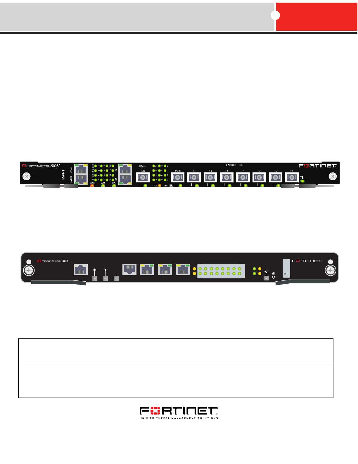
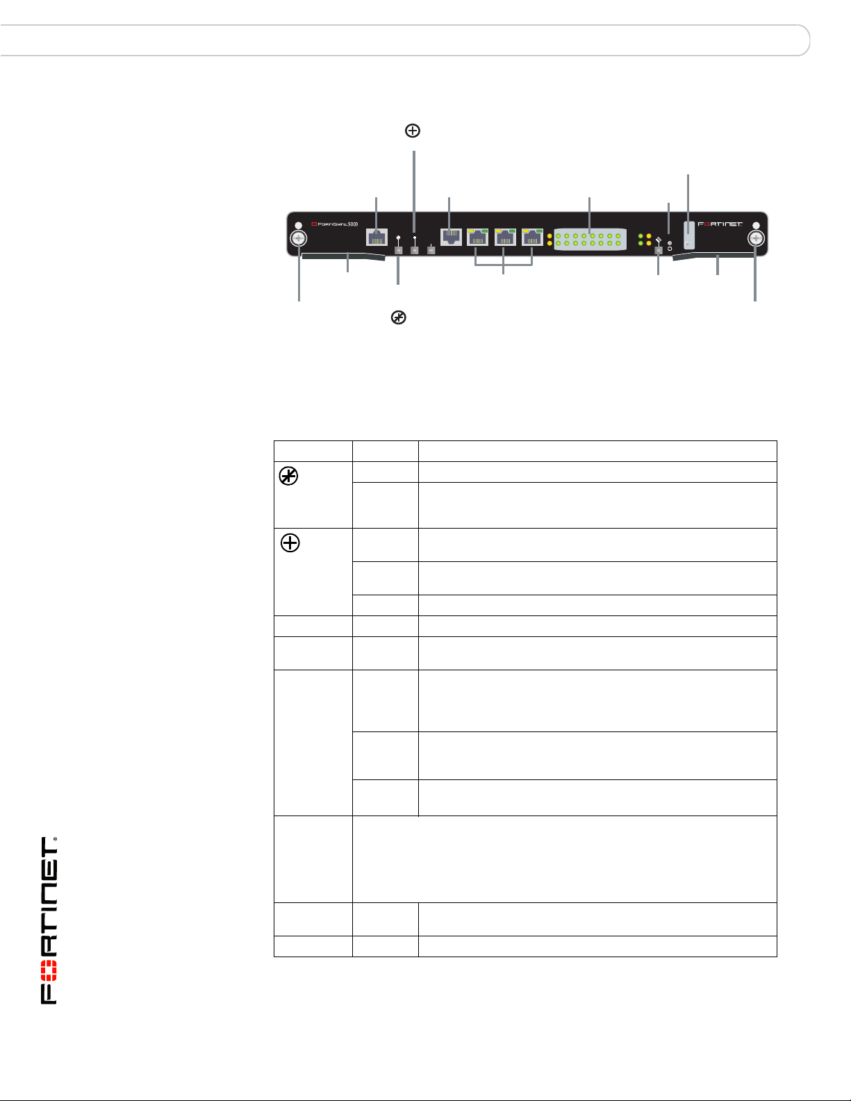
Figure 1: FortiSwitch-5003A front panel
Base Network
Activity LEDs
Fabric Network
Activity LEDs
B1 B2
Base 1G
Copper
Healthy
LED
Active
LED
BASE 10G Optical
or Copper SFP
Fault
LED
14/F8 F7 F6 F5 F4 F3 F2 F1
Fabric 10G Optical or Copper SFP
Reset
Switch
Hot Swap
LED
Retention
Screw
Extraction
Lever
Retention
Screw
Extraction
Lever
RJ-45 COM
Port
MGMT 1G
Copper
Interface
OOS
LED
• One front panel base backplane 10-gigabit optical or copper SFP+ interface
(BASE 10G) that connects to the base backplane channel
• Eight front panel fabric backplane 10-gigabit optical or copper SFP+ interfaces
(14/F8, F7, F6, F5, F4, F3, F2, and F1)
• One gigabit out of band management ethernet interface (MGMT)
• One RJ-45, RS-232 serial console connection (COM)
• Mounting hardware
• LED status indicators
• IEEE 802.1q VLANs
• IEEE 802.3ad static mode layer-2 link aggregation
• Link aggregation using a hash algorithm based on source and destination IP
addresses
• Multi-Spanning Tree Protocol (MSTP) (IEEE 802.1s) to support redundant
FortiSwitch-5003A boards and external MSTP-compatible switches
• Heartbeat between FortiGate-5001A and FortiGate-5005FA2 boards and the
FortiSwitch-5003A over the fabric channel to support MSTP (configurable from
the FortiGate-5001A and FortiGate-5005FA2 systems)
• Standard FortiOS command line interface (CLI) for configuring fabric switch
settings (VLANs, MSTP, trunks, and so on)
Front panel LEDs and connectors
From the FortiSwitch-5003A font panel you can view the status of the board LEDs
to verify that the board is functioning normally. The front panel includes a reset
switch for restarting the FortiSwitch-5003A board.
The front panel also contains connectors to the fabric and base channels, an out
of band management ethernet interface, and an RJ-45 RS-232 console port for
connecting to the FortiSwitch-5003A CLI.
FortiSwitch-5003A and 5003 Fabric and Base Backplane Communications Guide
10 01-30000-85717-20081205
Page 11
FortiSwitch-5003A system Front panel LEDs and connectors
LEDs
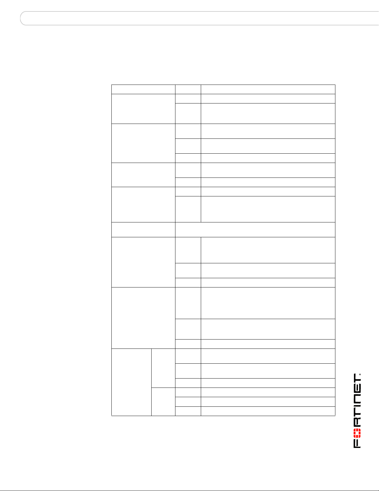
Ta bl e 2 lists and describes the FortiSwitch-5003A front panel LEDs.
Table 2: FortiSwitch-5003A front panel LEDs and switches
LED State Description
OOS (Out of Service) Off Normal operation.
Red Out of service. The LED turns on if the
ACT (Active) Green The FortiSwitch-5003A board is powered on and
Yellow Caution status. Caution status is indicated by the
Off The board is not connected to power.
HTY (Healthy) Green The FortiSwitch-5003A board is powered on and
Off The board health system has detected a fault.
FLT (Fault) Off Normal operation.
Yellow Cannot establish a link to a configured interface or
RST (Reset switch) Press and hold Reset for three seconds to restart the
Base Network Activity
LEDs
Fabric Network
Activity LEDs
MGMT, B1,
B2
(Management
and base
1-gigabit
LEDs)
Link/Act
(Left
LED)
Speed
(Right
LED)
FortiSwitch-5003A board.
Solid
Green
Blinking
Green
Off No link.
Solid
Green
Blinking
Green
Off No link.
Solid
Green
Blinking
Green
Off No Link
Green Connection at 1 Gbps.
Amber Connection at 100 Mbps.
Off Connection at 10 Mbps.
FortiSwitch-5003A board fails. The LED may also
flash briefly when the board is powering on.
operating normally.
fault condition of the HTY and FLT LEDs.
operating normally.
another connection problem external to the
FortiSwitch-5003A board. This LED may indicate
issues that do not affect normal operation.
Indicates this interface is connected to the 1-gigabit
base channel interface of a FortiGate-5000 board.
Table 3 on page 12 lists the base network activity
LEDs and the interface that each represents.
Indicates 1-gigabit network traffic on this interface.
Indicates this interface is connected to the
10/1-gigabit fabric channel interface of a
FortiGate-5000 board. Table 5 on page 14 lists the
fabric network activity LEDs and the interface that
each represents.
Indicates 10/1-gigabit network traffic on this interface.
Table 5 on page 14 lists the fabric network activity
LEDs and the interface that each represents.
Indicates this interface is connected with the correct
cable and the attached network device has power.
Indicates network traffic on this interface.
FortiSwitch-5003A and 5003 Fabric and Base Backplane Communications Guide
01-30000-85717-20081205 11
Page 12
Front panel LEDs and connectors FortiSwitch-5003A system
Table 2: FortiSwitch-5003A front panel LEDs and switches (Continued)
LED State Description
Solid
BASE 10G, 14/F8, F7,
F6, F5, F4, F3, F2, F1
(Base and Fabric 10
gigabit LEDs)
HS (Hot Swap) Blue The FortiSwitch-5003A is ready to be hot-swapped
Green
Blinking
Green
Off No link.
Flashing
Blue
Off Normal operation. The FortiSwitch-5003A board is in
Indicates this interface is connected to a 10-gigabit
network device with the correct cable and the
attached network device has power.
Indicates 10-gigabit network traffic on this interface.
(removed from the chassis). If the HS light is blue
and no other LEDs are lit the FortiSwitch-5003A
board has lost power
The FortiSwitch-5003A is changing from hot swap to
running mode or from running mode to hot swap.
This happens when the FortiSwitch-5003A board is
starting up or shutting down.
contact with the chassis backplane.
Base channel interfaces
Tab le 3 lists and describes the FortiSwitch-5003A base backplane channel
interfaces. The base backplane interfaces are not configurable or visible from the
FortiSwitch-5003A CLI.
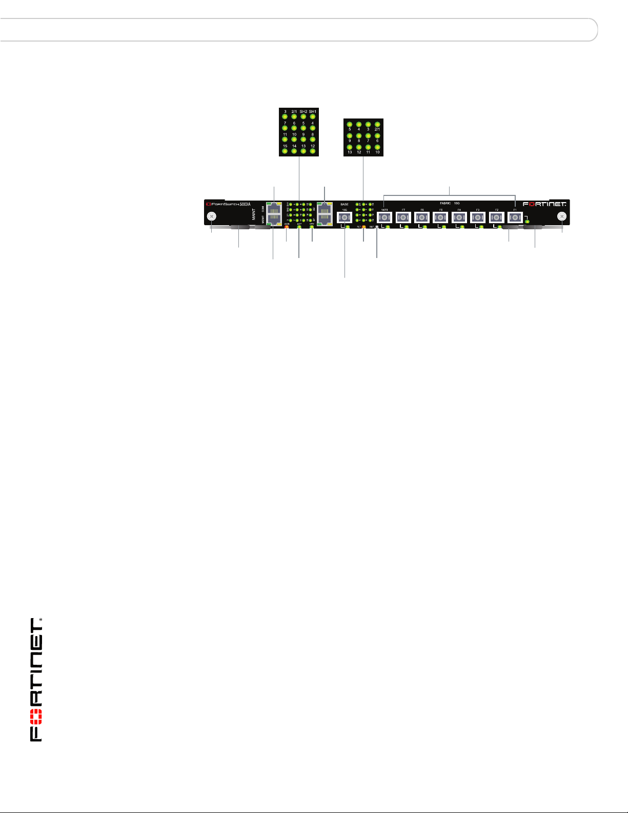
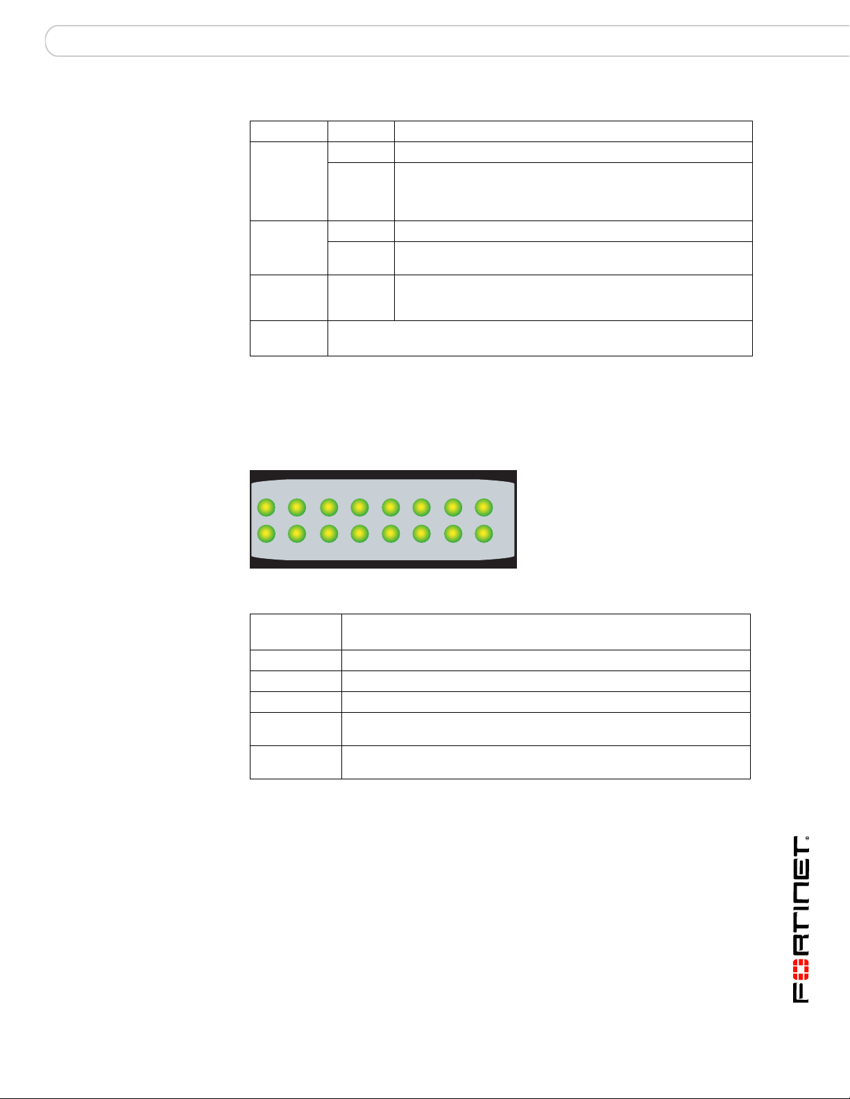
Figure 2: FortiSwitch-5003A base network activity LEDs
Table 3: Base channel interfaces and network activity LEDs
Interface
Name
SH1 If the FortiSwitch-5003A board is in the first hub/switch fabric slot, this
15 and SH2 Not used.
2/1 Base channel connection between base channels 1 and 2.
3 to 14 Base channel connection to FortiGate-5000 boards in chassis slots 3 to
Description
LED indicates a backplane connection to shelf manager 1. If the
FortiSwitch-5003A board is in second hub/switch fabric slot this LED
indicates a backplane connection to shelf manager 2.
This LED may not be lit even if a shelf manager is present if the shelf
manager is configured to use its front panel interface.
The 2/1 LED is lit if there is any board capable of connecting to the base
channel in the other slot. For example, if the FortiSwitch-5003A board is
installed in the first hub/switch fabric slot, this LED will be lit if any board
is installed in the second hub/switch fabric slot, including a
FortiSwitch-5003A board or any FortiGate-5000 board.
14.
FortiSwitch-5003A and 5003 Fabric and Base Backplane Communications Guide
12 01-30000-85717-20081205
Page 13
FortiSwitch-5003A system Front panel LEDs and connectors
Table 3: Base channel interfaces and network activity LEDs
Interface
Name
B1 and B2 Front panel gigabit base channel interfaces B1 and B2.
BASE 10G Front panel 10-gigabit base channel interface.
Fabric channel interfaces
Ta bl e 4 lists and describes the FortiSwitch-5003A fabric channel interfaces. You
can configure fabric interface settings, group fabric interfaces into trunks, and
configure MSTP spanning tree settings for fabric interfaces from the
FortiSwitch-5003A CLI.
Table 4: Fabric channel interfaces
Interface Name
Front Panel CLI*
2/1 slot-2/1 Interface between fabric channel 1 and fabric channel 2.
3 to 13 slot-3 to
14/F8 slot-14/f8 Front panel interface 14/F8.
F1 to F7 f1 to f7 Front panel 10-gigabit fabric interfaces F1 to F7.
* You can configure settings for FortiSwitch-5003A fabric interfaces from the
FortiSwitch-5003A CLI. The CLI columns show the names of the interfaces as they appear
on the FortiSwitch-5003A CLI.
Description
Use these interfaces to connect your network to the base channel, to
connect base channel 1 to base channel 2, or to connect a base channel
on one chassis to a base channel on another chassis.
Use this interface to connect a 10-gigabit network to the base channel.
10-gigabit communication is not supported across the base channels but
this interface is still available if you need to connect the base channel to
a 10-gigabit network.
Description
If there are two FortiSwitch-5003A boards installed in a
chassis this interface can be used to communicate between
them. In some configurations you may have to disable this
communication.
Fabric backplane slots 3 to 13.
slot-13
The 3 to 13 fabric network activity LEDs are lit if there are
FortiGate boards in chassis slots 3 to 13.
Fabric backplane slot 14 and front panel interface 14/F8
share the same FortiSwitch-5003A switch port. By default the
the front panel interface 14/F8 is enabled and fabric
backplane slot 14 is disabled. You can change this setting
using a switch on the FortiSwitch-5003A board.
Use these interfaces to connect your network to the fabric
channel, to connect fabric channel 1 to fabric channel 2, or to
connect a fabric channel on one chassis to a fabric channel
on another chassis.
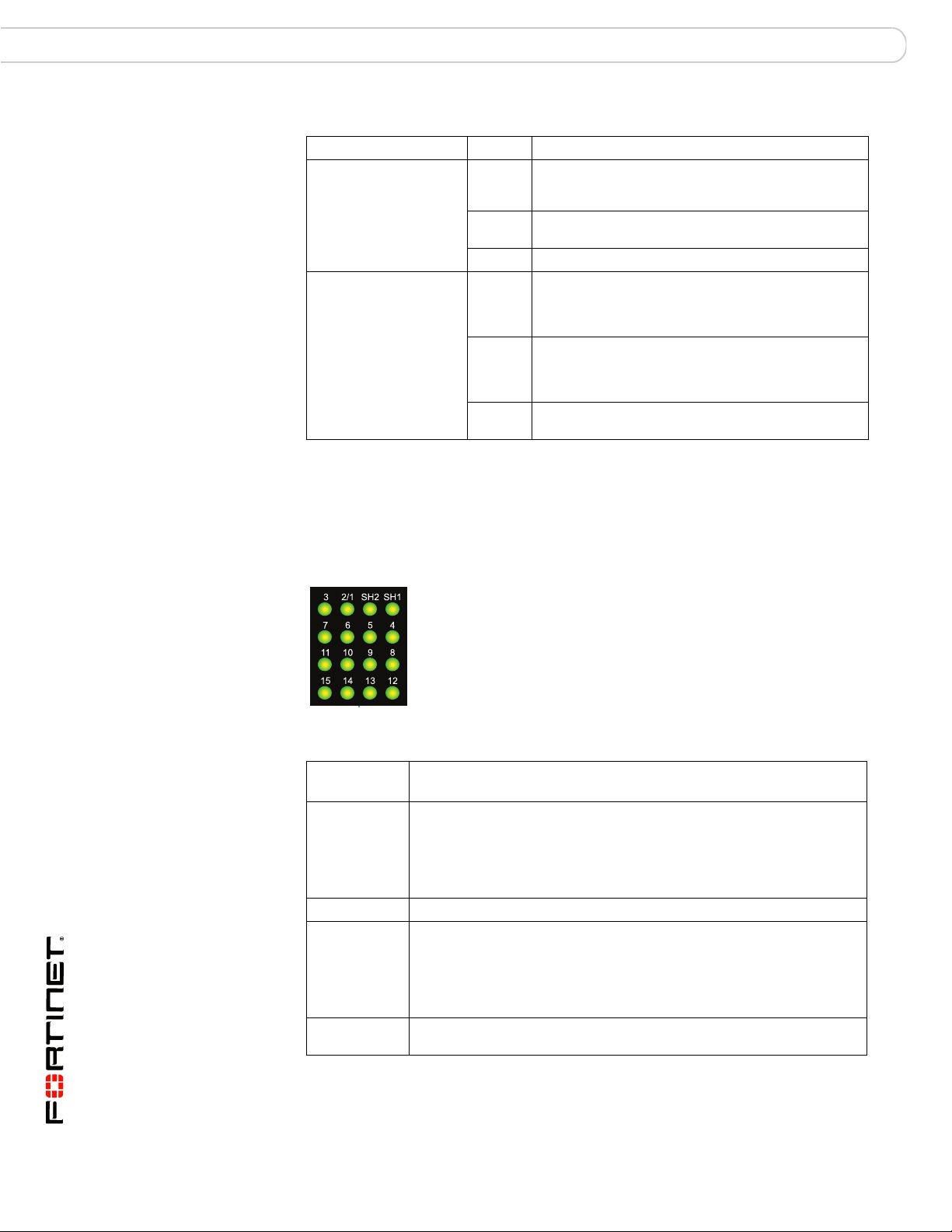
The fabric network activity LEDs show links and network activity for the interfaces
and connections listed in Tab le 5 .
Figure 3: FortiSwitch-5003A fabric network activity LEDs
FortiSwitch-5003A and 5003 Fabric and Base Backplane Communications Guide
01-30000-85717-20081205 13
Page 14
FortiSwitch-5003A configurations FortiSwitch-5003A system
Table 5: Fabric network activity LEDs
Fabric network
activity LED
2/1 Fabric channel connection between fabric channel 1 and fabric
3 to 13 Fabric backplane connection to FortiGate-5000 boards in chassis slots
Front panel connectors
Tab le 6 lists and describes the FortiSwitch-5003A front panel connectors.
Table 6: FortiSwitch-5003A connectors
Connector Type Speed Protocol Description
MGMT RJ-45 10/100/1000
COM RJ-45 9600 bps
B1, B2 RJ-45 10/100/1000
BASE 10G SFP+ 10 Gbps Ethernet SFP+ 10 gigabit connection to the base
FABRIC
10G, 14/F8,
F7, F6, F5,
F4, F3, F2,
F1
Interface or connection
channel 2. This LED is lit if there are two FortiSwitch-5003A boards
installed in the chassis to indicate fabric backplane communication
between them.
3 to 13.
Base-T
8/N/1
Base-T
SFP+ 10 Gbps Ethernet SFP+ 10 gigabit connection to the fabric
Ethernet Copper gigabit connection to out of band
RS-232
serial
Ethernet Copper gigabit connection to the base
management interface.
Serial connection to the command line
interface.
backplane channel.
backplane channel.
backplane channel.
FortiSwitch-5003A configurations
You can operate the FortiSwitch-5003A board as a fabric and base channel
layer-2 switch for any FortiGate-5000 board. The FortiSwitch-5003A board is
compatible with all FortiGate-5000 boards.
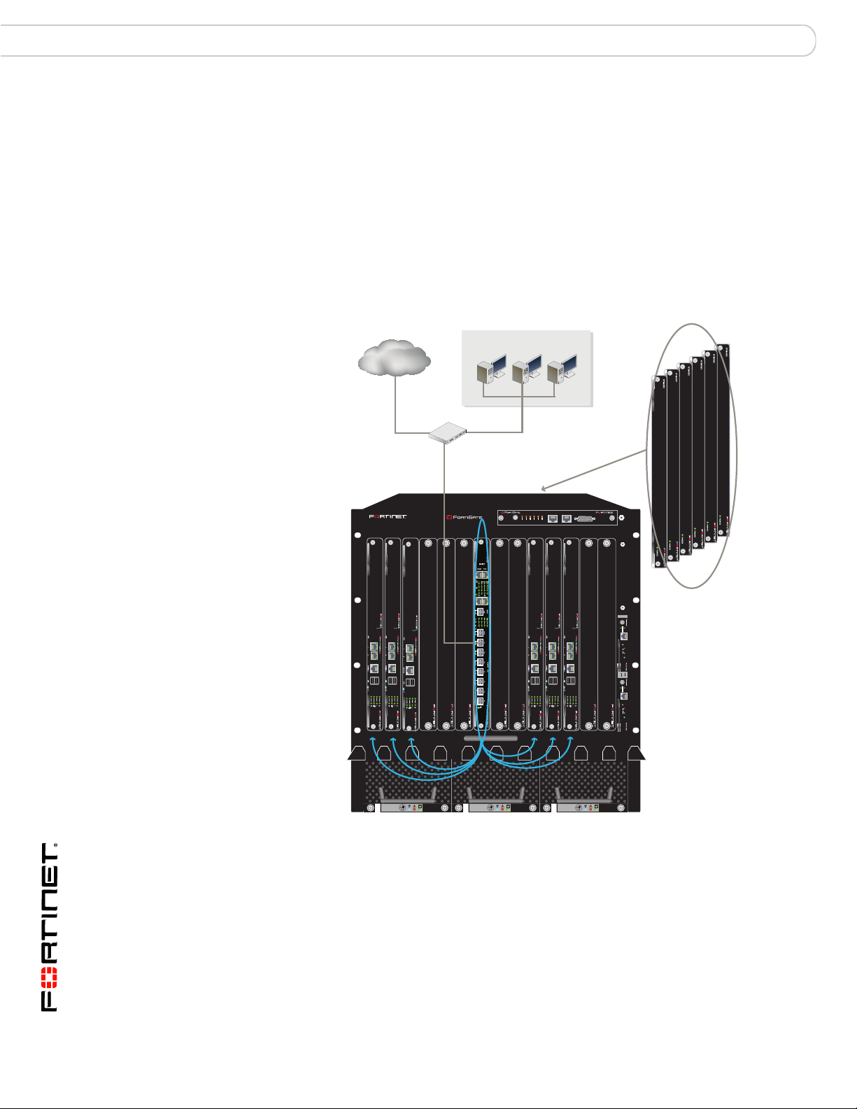
Base and fabric gigabit switching within a chassis
Figure 4 shows a FortiGate-5050 chassis with a FortiSwitch-5003A board in slot 1
and two FortiGate-5001A boards in slots 3 and 4. In this configuration the
FortiGate-5001A boards are using base channel 1 for HA heartbeat
communication. The FortiGate-5001A boards use base1 as the HA heartbeat
interface.
FortiSwitch-5003A and 5003 Fabric and Base Backplane Communications Guide
14 01-30000-85717-20081205
Page 15
FortiSwitch-5003A system FortiSwitch-5003A configurations
1
2
2
3
4
5
SMC
1
SMC
POWER
Base channel 1
HA Heartbeat
Communication
Figure 4: FortiSwitch-5003A base channel 1 HA heartbeat communication
5000SM
10/100
ETH0
Service
link/Act
ETH1
10/100
RESET
ETH0
link/Act
SERIAL
STATUS
Hot Swap
1
Fabric 10-gigabit switching within a chassis
One FortiGate-RTM-XB2 provides 10-gigabit connections to both
FortiGate-5001A fabric channels. The FortiGate-RTM-XB2 also provides NP2
packet acceleration for each fabric channel. To effectively use NP2 acceleration,
packets must be received by the FortiGate-5001A board on one fabric channel
and exit from the FortiGate-5001A board on the same fabric channel or on the
other fabric channel. See the FortiGate-RTM-XB2 System Guide for more
information.
Figure 5 shows a FortiGate-5050 chassis containing two FortiSwitch-5003A
boards and one FortiGate-5001A board. Using these components this chassis
supplies 10-gigabit connectivity between the external and internal network.
Figure 5: Example 10-gigabit connection between internal and external networks
Internal Network
Internal 10-gigabit
Network Connected
to Fabric Channel 2
5050SAP
ALARM
5000SM
10/100
ETH0
Service
link/Act
ETH1
SERIAL
2
FortiGate-RTM-XB2
module installed in RTM
slot 3 provides two
10-gigabit fabric channels
and NP2 acceleration for
the FortiGate-5001A board
STATUS
10/100
RESET
ETH0
link/Act
FortiGate-5001A Board
Installed in FortiGate-5050
front panel slot 3
Hot Swap
FortiSwitch-5003A and 5003 Fabric and Base Backplane Communications Guide
01-30000-85717-20081205 15
Fabric Channel 1
10 Gigabit Data
Communication
5
4
3
2
POWER
Fabric Channel 2
10-gigabit Data
Communication
1
5000SM
10/100
SMC
ETH0
Service
link/Act
ETH1
10/100
RESET
ETH0
link/Act
2
5050SAP
SERIAL
STATUS
Hot Swap
1
ALARM
External 10-gigabit
Network Connected
to Fabric Channel 1
5000SM
10/100
link/Act
ETH1
SERIAL
10/100
2
ETH0
link/Act
External
Network
SMC
ETH0
Service
STATUS
Hot Swap
RESET
1
Page 16
FortiSwitch-5003A configurations FortiSwitch-5003A system
Layer-2 link aggregation and redundancy configurations
The FortiSwitch-5003A board supports 802.3ad static mode layer-2 link
aggregation, 802.1q VLANs, and 802.1s Multi-Spanning Tree Protocol (MSTP) for
the fabric channels. You can use these features to configure link aggregation and
support redundant FortiSwitch-5003A configurations to distribute traffic to multiple
FortiGate-5001A or 5005FA2 boards.
Figure 6 shows a basic link aggregation configuration using a single
FortiSwitch-5003A board. In this configuration the external switch is connected to
FortiSwitch-5003A front panel f5 interface. The switch adds VLAN tags to traffic
from the internal and external networks.
Figure 6: Basic link aggregation configuration
External
Network
Internal and external
10-gigabit networks
connected to
FortiSwitch-5003A
front panel interface F7
and to fabric channel 1
1311975312468101214
External switch
VLAN
tagged
traffic
FILTER
Internal Network
5140SAP
5140
CAL
ITI
USER1
MINOR
MAJOR
CR
RESET
SERIAL 1 SERIAL 2 ALARM
USER2
USER3
Six FortiGate-RTM-XB2
modules installed in RTM
slots 6, 8, 9, 10, 11, and
5000SM
ETH1
ETH0
10/100
10/100
link/Act
link/Act
13 to provide 10-gigabit
fabric interfaces and
ETH0
Service
RESET
NP2 acceleration for each
STATUS
Hot Swap
FortiGate-5001A board
12
5000SM
ETH1
ETH0
10/100
10/100
link/Act
link/Act
ETH0
Service
RESET
STATUS
Hot Swap
0
Distributed 10-gigabit
data communication
on fabric channel 1
FAN TRAY FAN TRAYFAN TRAY
12
FortiSwitch-5003A and 5003 Fabric and Base Backplane Communications Guide
16 01-30000-85717-20081205
Page 17

FortiSwitch-5003 system Front panel LEDs and connectors
FortiSwitch-5003 system
The FortiSwitch-5003 board provides base backplane interface switching for the
FortiGate-5140 chassis and the FortiGate-5050 chassis. You can use this
switching for data communication or HA heartbeat communication between the
base backplane interfaces of FortiGate-5000 series boards installed in slots 3 and
up in these chassis. FortiSwitch-5003 boards can be used for base backplane
communication in a single chassis or between multiple chassis.
Install FortiSwitch-5003 boards in chassis slots 1 and 2. A FortiSwitch-5003 board
in slot 1 provides communications on base backplane interface 1. A
FortiSwitch-5003 board in slot 2 provides communications on base backplane
interface 2.
If your configuration includes only one FortiSwitch-5003 board you can install it in
slot 1 or slot 2 and configure the FortiGate-5000 boards installed in the chassis to
use the correct base backplane interface.
The FortiSwitch-5003 board includes the following features:
• A total of 16 10/100/1000Base-T gigabit ethernet interfaces:
• 13 backplane 10/100/1000Base-T gigabit interfaces for base backplane
switching between FortiGate-5000 series boards installed in the same
chassis as the FortiSwitch-5003
• Three front panel 10/100/1000Base-T gigabit interfaces (ZRE0, ZRE1,
ZRE2) for base backplane switching between two or more FortiGate-5000
series chassis
• One 100Base-TX out of band management ethernet interface (ETH0)
• RJ-45 RS-232 serial console connection (CONSOLE)
• Mounting hardware
• LED status indicators
Front panel LEDs and connectors
From the FortiSwitch-5003 font panel you can view the status of the board LEDs
to verify that the board is functioning normally. You can also connect the
FortiSwitch-5003 board in one chassis to a FortiSwitch-5003 board in another
chassis through the front panel ethernet connections. The front panel also
includes and out of band management ethernet interface and the RJ-45 console
port for connecting to the FortiSwitch-5003 CLI.
FortiSwitch-5003A and 5003 Fabric and Base Backplane Communications Guide
01-30000-85717-20081205 17
Page 18
Front panel LEDs and connectors FortiSwitch-5003 system
Figure 7: FortiSwitch-5003 front panel
Power LED
Management
100Base-TX
Ethernet
ETH
O
MANAGEMENT
CONSOLE
RJ-45
Serial
RS232ZRE0ZRE1ZRE2
SYSTEM
CONSOLE
ZRE Network
Activity LEDs
(ZRE 0 to 15)
E1
9876543210
1514
1312
1110
E0
LED Mode Switch
Reset
Switch
OKCLK
INTEXT
FLT
HOT SWAP
ZRE
RESET
LED MODE
FLT
LEDs
Mounting
Knot
Extraction
Lever
Out of
Service LED
ZRE0 ZRE1 ZRE2
base backplane interfaces
10/100/1000Base-T
Ethernet
Hot
Swap
LED
Extraction
Lever
Tab le 7 lists and describes the FortiSwitch-5003 board front panel LEDs.
Table 7: FortiSwitch-5003 board front panel LEDs and switches
LED State Description
Off Normal operation.
Red Out of service. The LED turns on if the FortiSwitch-5003 board
Green The FortiSwitch-5003 board is powered on and operating
Yellow Caution status. Caution status is indicated by the fault condition
Off The board is not connected to power.
System Off Normal operation.
E0, E1
ZRE 0-15
Yellow or
Green
Green Link/Activity mode: Blinking to indicate network traffic on this
(ZRE
network
activity
LEDs, LED
Yellow Link/Activity mode: The interface is disabled and cannot
Mode
switch
changes
Off Link/Activity mode: No link.
mode)
LED Mode
switch
Change the ZRE network activity LED display mode. Normally the ZRE
network activity LEDs operate in Link/Activity mode. In this mode the LEDs
flash green to indicate a link and to indicate network traffic.
Press this button to switch the ZRE LEDs to Link/Speed mode. In
Link/Speed mode the ZRE LEDs use a solid color to indicate a link. The
color of the LED indicates the speed of the link.
CLK Flashing
Green
OK Green Initialization completed successfully.
fails. The LED may also flash briefly when the board is
powering on.
normally.
of the CLOCK, OK or INT FLT LEDs.
Link status of out of band management interfaces (not used).
interface. Table 8 on page 19 lists the ZRE LEDs and the
interface that each represents.
Link/Speed mode: 100 Mbps connection.
forward packets. (not used)
Link/Speed mode: 1000 Mbps connection.
Link/Speed mode: 10 Mbps connection.
Initialization completed successfully.
Mounting
Knot
FortiSwitch-5003A and 5003 Fabric and Base Backplane Communications Guide
18 01-30000-85717-20081205
Page 19
FortiSwitch-5003 system Front panel LEDs and connectors
ZRE
1514
1312
1110
98
76
54
32
10
Table 7: FortiSwitch-5003 board front panel LEDs and switches (Continued)
LED State Description
EXT FLT Off Normal operation.
Yellow Cannot establish a link to a configured interface or another
INT FLT Off Normal operation.
Yellow Failure of internal tests. Indicates a hardware or software
Hot Swap Blue Indicates the FortiSwitch-5003 board is ready to be hot
Reset
switch
Press and hold Reset for three seconds to restart the FortiSwitch-5003
board.
connection problem external to the FortiSwitch-5003 board.
This LED may indicate issues that do not affect normal
operation.
problem with the FortiSwitch-5003 board.
swapped. During a hot swap, the LED is on. The LED turns off
when the FortiSwitch-5003 board is correctly installed.
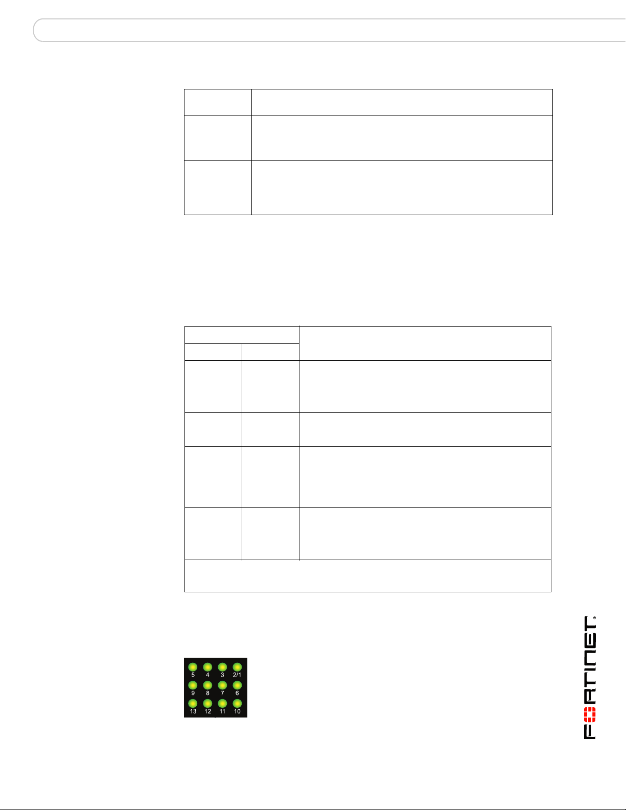
About the ZRE network activity LEDs
The ZRE network activity LEDs show links and network activity for the interfaces
and connections listed in Tab le 8 .
Figure 8: FortiSwitch-5003 ZRE network activity LEDs
Table 8: ZRE network activity LEDs FortiSwitch-5003 interfaces and connections
ZRE network
activity LED
0 ZRE0 front panel interface.
1 ZRE1 front panel interface.
2 ZRE2 front panel interface.
3 to 14 Base backplane connection to FortiGate-5000 series boards in chassis
15 Base backplane link. Indicates that the FortiSwitch-5003 board can
Interface or connection
slots 3 to 14.
connect to the base backplane interface.
FortiSwitch-5003A and 5003 Fabric and Base Backplane Communications Guide
01-30000-85717-20081205 19
Page 20
Base backplane communications FortiSwitch-5003 system
Connectors
Tab le 9 lists and describes the FortiSwitch-5003 front panel connectors.
Table 9: FortiSwitch-5003 connectors
Connector Type Speed Protocol Description
ETH0 RJ-45 100Base-T Ethernet Front panel out of band management
CONSOLE RJ-45 9600 bps RS-232
ZRE0,
ZRE1,
ZRE2
RJ-45 10/100/1000
Base-T
serial
Ethernet Redundant connections to another
interface. A second out of band
management interface, ETH1, connects to
the shelf managers. Neither of the out of
band management interfaces are used.
Serial connection to the command line
interface.
FortiSwitch-5003 board in an different
FortiGate-5140 or FortiGate-5050 chassis.
Use these interfaces for base backplane
interface connections between
FortiGate-5000 series chassis.
Base backplane communications
This section provides a brief introduction to using FortiSwitch-5003 boards for
base backplane communication.
FortiSwitch-5003 boards installed in a FortiGate-5140 or FortiGate-5050 chassis
in slot 1 or slot 2 provide base backplane switching for all of the FortiGate-5000
series boards installed in chassis slots 3 and above. Base backplane switching
can be used for HA heartbeat communication and for data communication
between FortiGate-5000 series boards.
The FortiGate-5000 series boards can all be installed in the same chassis, or you
can use the FortiSwitch-5003 front panel ZRE interfaces for base backplane
communication among multiple FortiGate-5140 and FortiGate-5050 chassis. The
communication can be among a collection of the same chassis (for example,
multiple FortiGate-5050 chassis) or among a mixture of FortiGate-5140 and
FortiGate-5050 chassis. In most cases you would connect the same base
backplane interfaces together, but you can also use the FortiSwitch-5003 front
panel ZRE interfaces for connections between base backplane interface 1 and
base backplane interface 2. Again these connections can be within the same
chassis or among multiple chassis.
A FortiSwitch-5003 board in slot 1 provides communications on base backplane
interface 1. The FortiGate-5001SX and the FortiGate-5001FA2 boards
communicate with base backplane interface 1 using the interface named port9.
The FortiGate-5005FA2 board communicates with base backplane interface 1
using the interface named base1.
A FortiSwitch-5003 board in slot 2 provides communications on base backplane
interface 2. The FortiGate-5001SX and the FortiGate-5001FA2 boards
communicate with base backplane interface 2 using the interface named port10.
The FortiGate-5005FA2 board communicates with base backplane interface 2
using the interface named base2.
FortiSwitch-5003A and 5003 Fabric and Base Backplane Communications Guide
20 01-30000-85717-20081205
Page 21

FortiSwitch-5003 system Base backplane communications
In a single chassis, more than one cluster can use the same base backplane
interface for HA heartbeat communication. To separate heartbeat communication
for multiple clusters on the same base backplane interface, configure a different
HA group name and password for each cluster.
In a single chassis, you can also use the same base backplane interface for data
and HA heartbeat communication. If you are operating multiple clusters and
multiple data paths on the same base backplane interface you may experience
some bandwidth limitations. To increase the amount of bandwidth available you
can add a second FortiSwitch-5003 board and use both backplane interfaces for
HA heartbeat and data communication.
If you have two FortiSwitch-5003 boards and two backplane interfaces available
you can balance the traffic between the base backplane interfaces by how you
configure your FortiGate-5000 board data interfaces and HA heartbeat interfaces.
For example, if you have two busy FortiGate-5001SX clusters you might configure
one cluster to use port9 for HA heartbeat traffic and the other to use port10. If you
have a number of data paths that use the same base backplane interfaces you
can change the configuration to distribute traffic between both base backplane
interfaces.
FortiSwitch-5003A and 5003 Fabric and Base Backplane Communications Guide
01-30000-85717-20081205 21
Page 22

Base backplane communications FortiSwitch-5003 system
FortiSwitch-5003A and 5003 Fabric and Base Backplane Communications Guide
22 01-30000-85717-20081205
Page 23
FortiGate-5140 fabric backplane communication
FortiGate-5140 fabric backplane
communication
The FortiGate-5140 chassis has two fabric backplane Ethernet channels that can
operate at 1 Gbps or 10 Gbps. Available connections to these channels vary by
chassis hub/switch slot number.
• Hub/switch slot 1 can connect to the first fabric backplane channel (channel 1),
and thereby all other chassis slots, except hub/switch slot 2.
• Hub/switch Slot 2 can connect the to the second fabric backplane channel
(channel 2), and thereby all other chassis slots, except hub/switch slot 1.
• Other slots can connect to either or both channels, but only directly reach
hub/switch slot 1 or hub/switch slot 2. Connections to other slots through the
fabric backplane channels must pass through hub/switch slot 1 or hub/switch
slot 2.
Note: For more information on chassis architecture, see ATCA (Advanced Telecom
Computing Architecture) specifications.
Because of the fabric backplane dual star topology, connecting to or through the
fabric backplane requires FortiSwitch-5003A boards installed in hub/switch slot 1,
hub/switch slot 2, or both. FortiSwitch-5003A front panel fabric interfaces can also
connect the chassis fabric backplane channels to external devices, such as a
management computer, the network, or the fabric backplane of another chassis.
Note: FortiSwitch-5003 boards do not support fabric backplane switching.
FortiGate-5001A boards and FortiGate-5005FA2 boards can connect to the fabric
backplane at 1 Gbps. With the addition of a FortiGate-RTM-XB2 modules,
FortiSwitch-5001A boards can also connect to the fabric backplane at 10 Gbps.
The FortiGate-5001SX board and FortiGate-5001FA2 board do not include fabric
backplane interfaces.
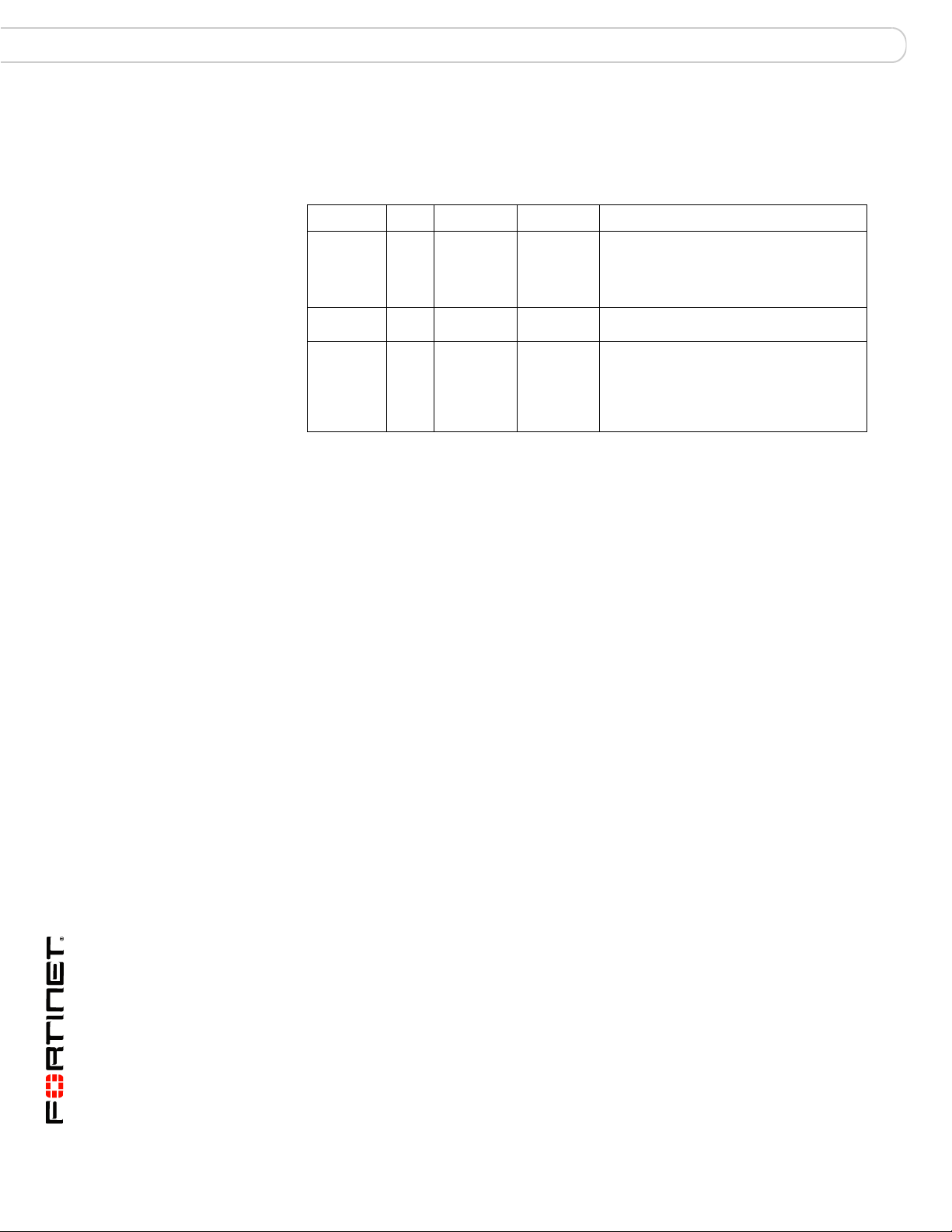
Table 10: Names of fabric backplane interfaces by FortiGate model
Model Name of fabric backplane
interface 1 (to slot 1)
FortiGate-5001A fabric1 fabric2
FortiGate-5005FA2 fabric1 fabric2
FortiGate-5001FA2 N/A N/A
FortiGate-5001SX N/A N/A
Name of fabric backplane
interface 2 (to slot 2)
FortiSwitch-5003A and 5003 Fabric and Base Backplane Communications Guide
01-30000-85717-20081205 23
Page 24
Fabric gigabit switching within a chassis FortiGate-5140 fabric backplane communication
1311975312468101214
5140
FILTER
12
0
12
Fabric channel 1
data communication
This section describes:
• Fabric gigabit switching within a chassis
• Fabric channel connections between FortiSwitch-5003A boards
• Fabric gigabit switching between chassis
• Fabric gigabit switching to the network
• Fabric 10-gigabit switching within a chassis
• Fabric channel layer-2 link aggregation
• Fabric channel layer-2 link aggregation and redundancy
• Example active-passive redundant link configuration
• Example active-active redundant link configuration
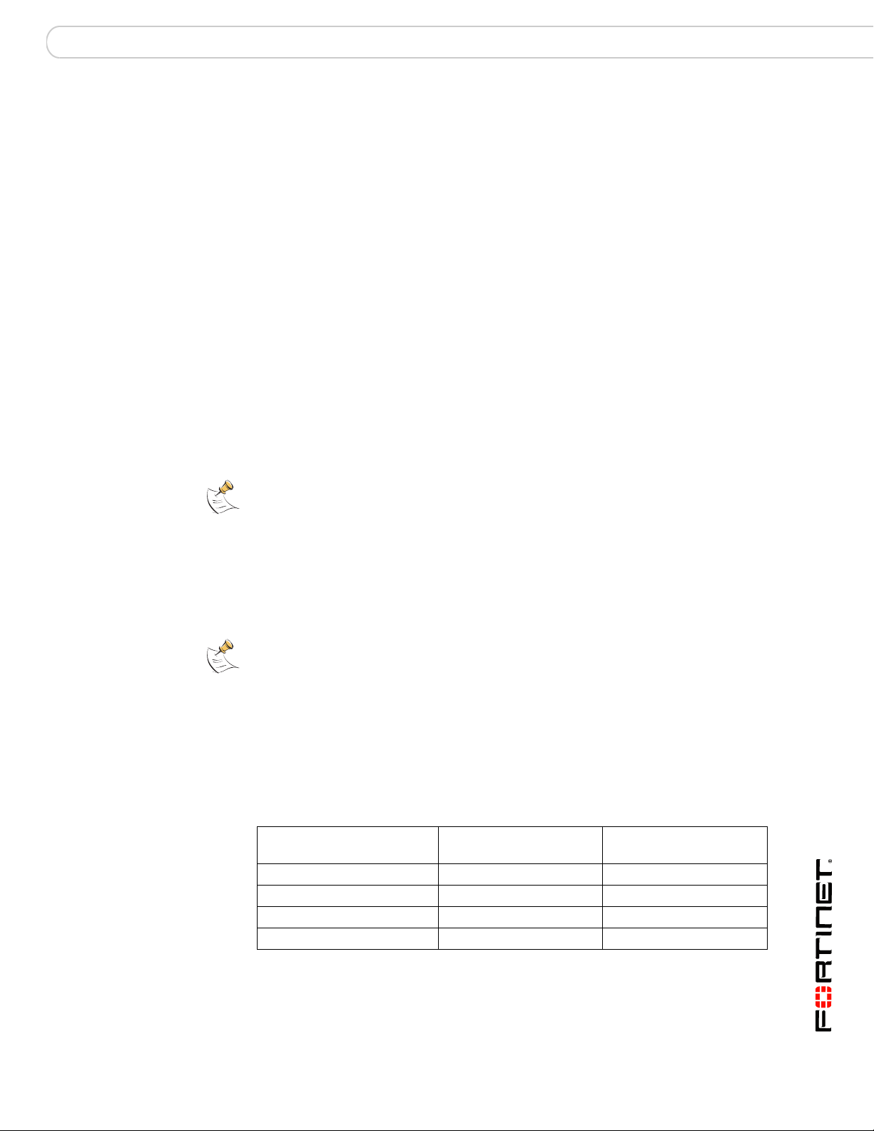
Fabric gigabit switching within a chassis
You can use FortiSwitch-5003A fabric channel switching for communication
between the fabric backplane interfaces of FortiGate-5001A or 5005FA2 boards
installed in a FortiGate-5140 chassis.
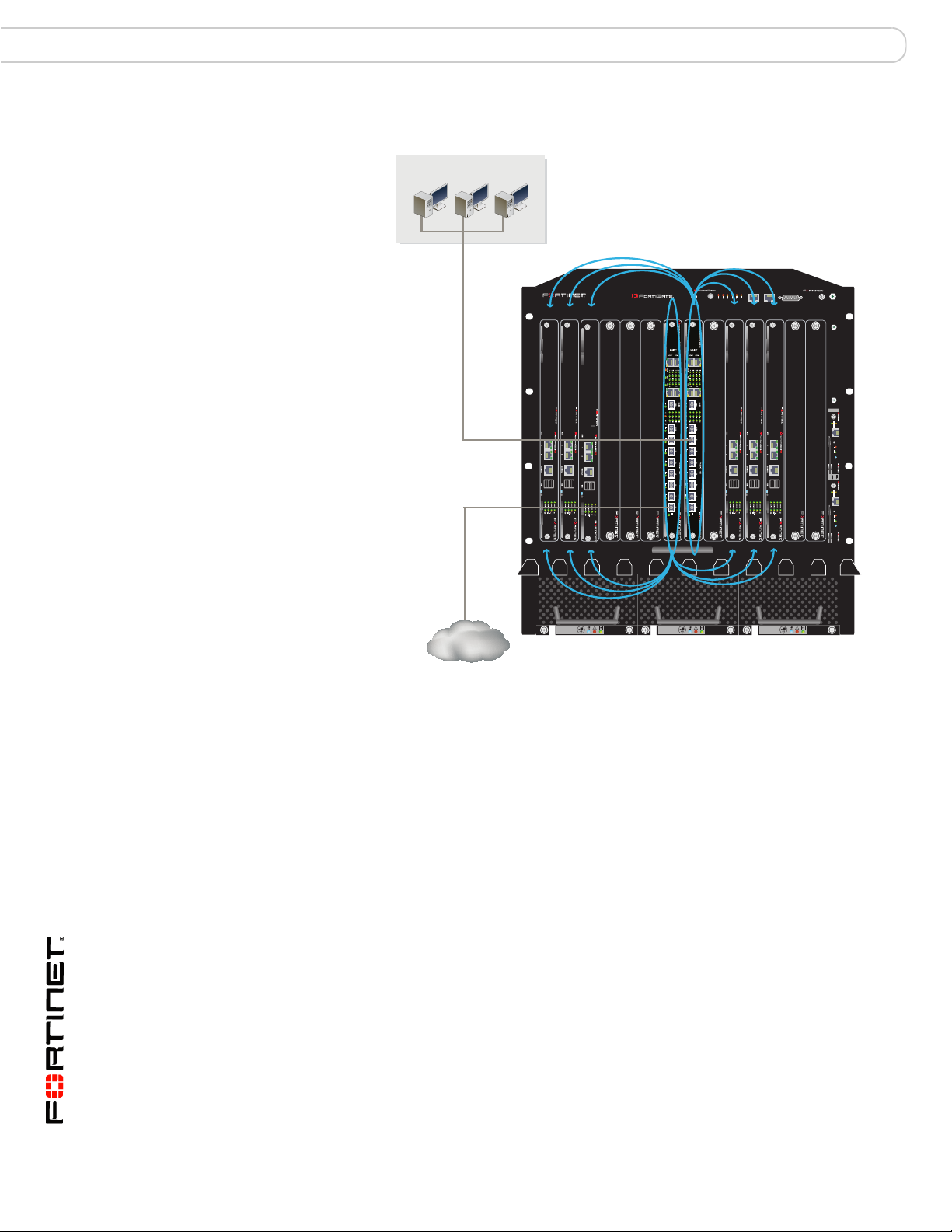
Figure 9 shows a FortiGate-5140 chassis with a FortiSwitch-5003A board in
hub/switch slot 1, and FortiGate-5001A boards in 6 other slots. In this
configuration the FortiSwitch-5003A board provides 1-gigabit fabric backplane
switching for the FortiGate-5001A fabric1 interfaces. The FortiSwitch-5003A
boards operate as layer-2 switches and the FortiGate-5001A boards operate as
typical standalone FortiGate units.
Figure 9: FortiGate-5140 fabric channel 1 data communication
5140SAP
SERIAL 1 SERIAL 2 ALARM
USER2
USER3
USER1
MINOR
MAJOR
CRITICAL
RESET
5000SM
ETH1
ETH0
10/100
10/100
link/Act
link/Act
ETH0
Service
RESET
STATUS
Hot Swap
5000SM
ETH1
ETH0
10/100
10/100
link/Act
link/Act
ETH0
Service
RESET
STATUS
Hot Swap
FAN TRAY FAN TRAYFAN TRAY
FortiSwitch-5003A and 5003 Fabric and Base Backplane Communications Guide
24 01-30000-85717-20081205
Page 25

FortiGate-5140 fabric backplane communication Fabric gigabit switching within a chassis
The chassis can be connected to the network using any of the FortiGate-5001A
front panel interfaces. You can also connect FortiSwitch-5003A front panel fabric
interfaces to the network. You can also install FortiGate AMC modules in the
FortiGate-5001A boards and connect the network to the AMC front panel
interfaces. The AMC modules and the network connections are not shown in
Figure 9.
For the FortiGate-5001A boards to use the fabric channel 1 for data
communication you must show backplane interfaces on the FortiGate-5001A
web-based manager and then configure firewall polices and routing for the fabric1
interfaces.
If the data traffic contains VLAN-tagged packets, you must add the VLAN tags to
the FortiSwitch-5003A interfaces that will handle the VLAN-tagged traffic. For
example, to allow VLAN tags 201 to 210 on slots 9, 11, and 13 from the
FortiSwitch-5003A CLI enter:
config switch fabric-channel interface
edit "slot-9"
set allowed-vlans 1,201-210
next
edit "slot-11"
set allowed-vlans 1,201-210
next
edit "slot-13"
set allowed-vlans 1,201-210
end
For more information about the FortiSwitch-5003A CLI, see “FortiSwitch-5003A
CLI reference” on page 89.
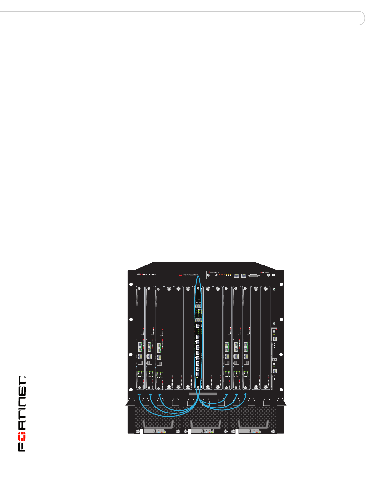
Figure 10 shows a FortiGate-5140 chassis with FortiSwitch-5003A boards in
hub/switch slots 1 and 2 and FortiGate-5001A and 5005FA2 boards in all of the
other slots. The FortiGate boards can use fabric channels 1 and 2 for data
communication among the FortiGate boards. In this configuration the
FortiSwitch-5003A boards are operating as layer-2 switches for fabric channels 1
and 2 and the FortiGate boards are operating as typical standalone FortiGate
units.
The chassis can be connected to the network using any of the FortiGate front
panel interfaces. You can also connect FortiSwitch-5003A front panel fabric
interfaces to the network. You can also install FortiGate AMC modules in the
FortiGate-5001A boards and connect the network to the AMC front panel
interfaces. The AMC modules and the network connections are not shown in
Figure 10.
FortiSwitch-5003A and 5003 Fabric and Base Backplane Communications Guide
01-30000-85717-20081205 25
Page 26
Fabric gigabit switching within a chassis FortiGate-5140 fabric backplane communication
Figure 10: FortiGate-5140 fabric channel 1 and 2 data communication
Fabric channel 2
data communication
5140SAP
5140
E
S
E
R
1311975312468101214
LINK
CONSOLE
OOS ACC STATUS
IPM
L
R
A
C
T
I
JO
IN
IT
A
R
M
M
C
LINK
ACT
ACT
FABRIC
BASE
OOS ACC STATUS
USB USB
3 412 56
IPM
78
2
1
R
R
R
O
E
E
S
S
U
U
LINK
LINK
ACT
FABRIC
BASE
CONSOLE
3 412 56
SERIAL 1 SERIAL 2 ALARM
3
R
E
S
U
LINK
LINK
ACT
ACT
ACT
FABRIC
BASE
CONSOLE
OOS ACC STATUS
USB USB
USB USB
3 412 56
IPM
78
78
LINK
ACT
FABRIC
BASE
CONSOLE
OOS ACC STATUS
IPM
LINK
LINK
LINK
ACT
ACT
FABRIC
BASE
CONSOLE
OOS ACC STATUS
USB USB
3 412 56
3 412 56
IPM
78
LINK
LINK
ACT
ACT
ACT
FABRIC
BASE
CONSOLE
OOS ACC STATUS
USB USB
USB USB
3 412 56
IPM
78
78
5000SM
ETH1
ETH0
10/100
10/100
link/Act
link/Act
ETH0
Service
RESET
STATUS
Hot Swap
12
5000SM
ETH1
ETH0
10/100
10/100
link/Act
link/Act
ETH0
Service
RESET
STATUS
Hot Swap
FILTER
0
FAN TRAY FAN TRAYFAN TRAY
12
Fabric channel 1
data communication
For the FortiGate boards to use the fabric channels 1 and 2 for data
communication you must show backplane interfaces on the FortiGate web-based
manager and then configure firewall polices and routing for the fabric1 and fabric2
interfaces.
If the data traffic contains VLAN-tagged packets, you must add the VLAN tags to
the FortiSwitch-5003A interfaces that will handle the VLAN-tagged traffic. For
example, to allow VLAN tag 400 on slots 4 and 12 from the FortiSwitch-5003A CLI
enter:
config switch fabric-channel interface
edit "slot-4"
set allowed-vlans 1,400
next
edit "slot-12"
set allowed-vlans 1,400
end
FortiSwitch-5003A and 5003 Fabric and Base Backplane Communications Guide
26 01-30000-85717-20081205
Page 27

FortiGate-5140 fabric backplane communication Fabric channel connections between FortiSwitch-5003A boards
Fabric channel connections between FortiSwitch-5003A boards
When two FortiSwitch-5003A boards are installed in a single chassis their fabric
channels are connected together. This means there is a data connection between
fabric channel 1 and fabric channel 2. Unless you are going to use this connection
you should disable it.
If one or more of the FortiGate-5001A or 5005FA2 boards are operating in
transparent mode, the connection between the fabric channels can cause looping.
If you have one or more FortiGate-5001A or 5005FA2 boards operating in
transparent mode with two FortiSwitch-5003A boards in the same chassis you
must disable communication between the FortiSwitch-5003A boards.
The fabric channel connection between the FortiSwitch-5003A boards uses an
internal FortiSwitch-5003A interface called slot-2/1. To disable the fabric channel
connection between two FortiSwitch-5003A boards you should set the status of
slot-2/1 to down for one of the boards. Connect to the CLI of one of the
FortiSwitch-5003A boards and enter the following command:
config switch fabric-channel physical-port
edit slot-2/1
set status down
end
Fabric gigabit switching between chassis
You can use the FortiSwitch-5003A front panel fabric interfaces to provide
10-gigabit data communications between the fabric channels of any combination
of FortiGate-5050 and FortiGate-5140 chassis.
Note: Its not required, but in most cases you would connect the same fabric channels
together. That is you would connect fabric channel 1 on one chassis to fabric channel 1 on
another. Usually you would not connect fabric channel 1 on one chassis to fabric channel 2
on another chassis. Also, you would usually not connect a base channel from one chassis
to a fabric channel on another chassis. You should be careful of looping when connecting
chassis together if some of the FortiGate boards in the chassis are operating in transparent
mode.
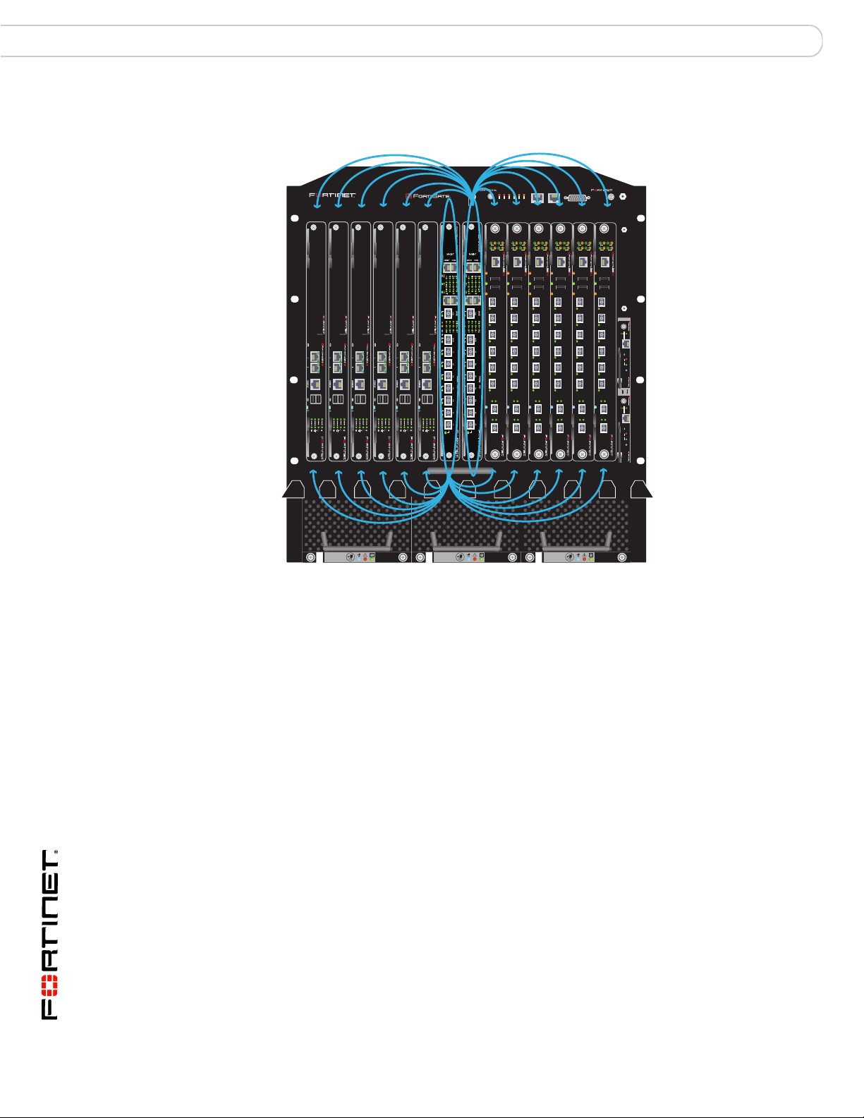
Figure 11 shows data communication between two FortiGate-5140 chassis using
fabric channel 1. The top chassis in the figure contains a FortiSwitch-5003A board
in hub/switch slot 1 and six FortiGate-5001A boards. The bottom chassis contains
a FortiSwitch-5003A board also in hub/switch slot 1 and four FortiGate-5005FA2
boards.
The chassis are connected together using the FortiSwitch-5003A F1 front panel
interface in the top chassis and the FortiSwitch-5003A F7 front panel interface in
the bottom chassis.
In this configuration the FortiSwitch-5003A boards are operating as layer-2
switches for fabric channel 1 and the FortiGate-5001A and 5005FA2 boards are
operating as typical standalone FortiGate units.
FortiSwitch-5003A and 5003 Fabric and Base Backplane Communications Guide
01-30000-85717-20081205 27
Page 28
Fabric gigabit switching between chassis FortiGate-5140 fabric backplane communication
The chassis can be connected to the network using any of the FortiGate front
panel interfaces. You can also connect FortiSwitch-5003A front panel fabric
interfaces to the network. You can also install FortiGate AMC modules in the
FortiGate-5001A boards and connect networks to the AMC front panel interfaces.
The AMC modules and the network connections are not shown in Figure 11.
Figure 11: Fabric channel 1 data communication between two FortiGate-5140
chassis
5140SAP
5140
1311975312468101214
FILTER
SERIAL 1 SERIAL 2 ALARM
USER2
USER1
USER3
MINOR
MAJOR
CRITICAL
RESET
5000SM
ETH1
ETH0
10/100
10/100
link/Act
link/Act
ETH0
Service
RESET
STATUS
Hot Swap
12
5000SM
ETH1
ETH0
10/100
10/100
link/Act
link/Act
ETH0
Service
RESET
STATUS
Hot Swap
0
Fabric channel 1
data communication
FAN TRAY FAN TRAYFAN TRAY
12
Fabric channel 1
10-gigabit data
communication
between 2 chassis
5140SAP
5140
1311975312468101214
LINK
LINK
LINK
LINK
ACT
ACT
ACT
ACT
FABRIC
FABRIC
BASE
BASE
CONSOLE
CONSOLE
OOS ACC STATUS
OOS ACC STATUS
USB USB
USB USB
3 412 56
3 412 56
IPM
IPM
78
78
SERIAL 1 SERIAL 2 ALARM
USER2
USER1
USER3
MINOR
MAJOR
CRITICAL
RESET
LINK
LINK
LINK
LINK
ACT
ACT
ACT
ACT
FABRIC
FABRIC
BASE
BASE
CONSOLE
CONSOLE
OOS ACC STATUS
OOS ACC STATUS
USB USB
USB USB
3 412 56
3 412 56
IPM
IPM
78
78
5000SM
ETH1
ETH0
10/100
10/100
link/Act
link/Act
ETH0
Service
RESET
STATUS
Hot Swap
12
5000SM
ETH1
ETH0
10/100
10/100
link/Act
link/Act
ETH0
Service
RESET
STATUS
Hot Swap
FILTER
0
Fabric channel 1
data communication
FAN TRAY FAN TRAYFAN TRAY
12
For the FortiGate-5001A and 50005FA2 boards to use fabric channel 1 for data
communication you must show backplane interfaces on the FortiGate web-based
manager and then configure firewall polices and routing for the fabric1 interfaces.
FortiSwitch-5003A and 5003 Fabric and Base Backplane Communications Guide
28 01-30000-85717-20081205
Page 29

FortiGate-5140 fabric backplane communication Fabric gigabit switching to the network
If the data traffic contains VLAN-tagged packets, you must add the VLAN tags to
the FortiSwitch-5003A interfaces that will handle the VLAN-tagged traffic. For
example, to allow VLAN tags 201 to 210 on slots 8 and 10 and the F7 front panel
interface, from the FortiSwitch-5003A CLI enter:
config switch fabric-channel interface
edit "slot-8"
set allowed-vlans 1,201-210
next
edit "slot-10"
set allowed-vlans 1,201-210
next
edit "f7"
set allowed-vlans 1,201-210
end
Fabric gigabit switching to the network
You can use the FortiSwitch-5003A fabric front panel interfaces to connect the
fabric channel of a chassis to your network. Most often you would do this for data
communication between the network and a fabric channel. For a simple 10-gigabit
connection from your network to a fabric channel you can connect your network
directly to a FortiSwitch-5003A fabric channel front panel interface. This
connection provides data communication to the fabric1 or fabric2 interfaces of the
FortiGate-5000 boards installed in the chassis.
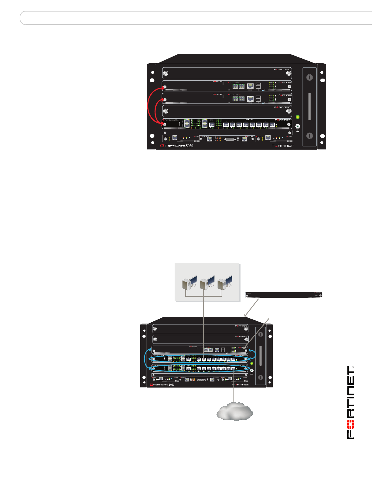
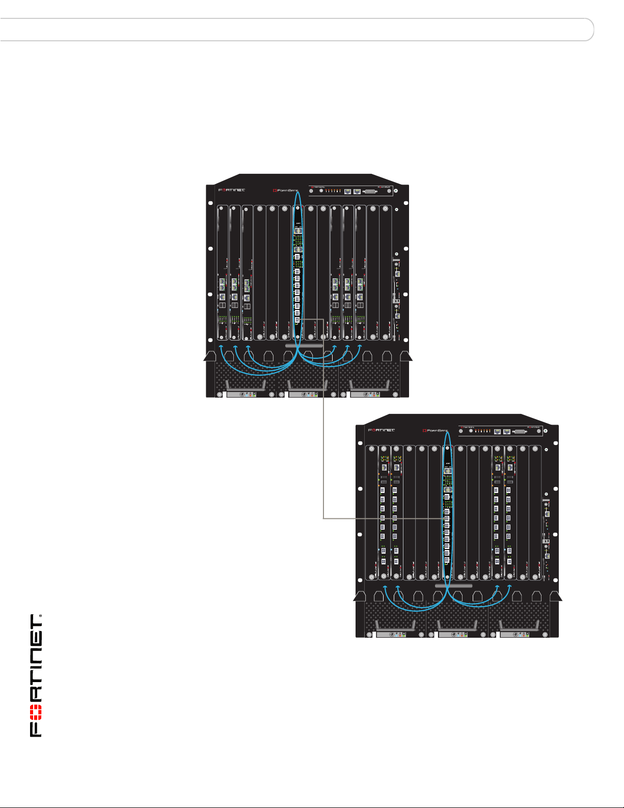
Figure 12 shows a FortiGate-5140 chassis containing two FortiSwitch-5003A
boards and 6 FortiGate-5001A boards. The chassis is connected to internal and
an external networks using FortiSwitch-5003A front panel fabric interfaces:
• The internal network is connected to fabric channel 2 using the F7 front panel
interface of the FortiSwitch-5003A board in hub/switch slot 2
• The external network is connected to fabric channel 1 using the F1 front panel
interface of the FortiSwitch-5003A board in hub/switch slot 1
In this configuration the FortiSwitch-5003A boards are operating as layer-2
switches and the FortiGate-5001A boards are operating as standalone FortiGate
units.
The chassis can also be connected to the network using any of the FortiGate front
panel interfaces. You can also install FortiGate AMC modules in the
FortiGate-5001A boards and connect networks to the AMC front panel interfaces.
The AMC modules and network connections to the AMC modules and FortiGate
boards are not shown in Figure 12.
If you have two FortiSwitch-5003A boards installed in a chassis you may need to
block communication between fabric channel 1 and fabric channel 2. See “Fabric
channel connections between FortiSwitch-5003A boards” on page 27 for more
information.
FortiSwitch-5003A and 5003 Fabric and Base Backplane Communications Guide
01-30000-85717-20081205 29
Page 30
Fabric gigabit switching to the network FortiGate-5140 fabric backplane communication
Figure 12: Fabric channel 2 connected to an internal network and fabric channel 1
connected to an external network
Internal Network
Fabric channel 2
Internal network connected
to the F7 front panel fabric
interface to connect to
fabric channel 2
1311975312468101214
data communication
5140
FILTER
5140SAP
SERIAL 1 SERIAL 2 ALARM
R3
R1
ET
USER2
USE
USE
MINOR
MAJOR
CRITICAL
RES
5000SM
ETH1
ETH0
10/100
10/100
link/Act
link/Act
ETH0
Service
RESET
STATUS
Hot Swap
12
5000SM
ETH1
ETH0
10/100
10/100
link/Act
link/Act
ETH0
Service
RESET
STATUS
Hot Swap
External network connected
to the F1 front panel fabric
interface to connect to
fabric channel 1
External
Network
0
Fabric channel 1
data communication
FAN TRAY FAN TRAYFAN TRAY
12
For the FortiGate-5001A boards to use the fabric channels for data
communication you must show backplane interfaces on the FortiGate web-based
manager and then configure firewall polices and routing for the fabric1 and fabric2
interfaces.
If the data traffic contains VLAN-tagged packets, you must add the VLAN tags to
the FortiSwitch-5003A interfaces that will handle the VLAN-tagged traffic. For
example, to allow VLAN tags 201 to 210 on slots 6, 8, and 10 and the F1 front
panel interface, from the FortiSwitch-5003A CLI enter:
config switch fabric-channel interface
edit "slot-6"
set allowed-vlans 1,201-210
next
edit "slot-8"
set allowed-vlans 1,201-210
next
edit "slot-10"
set allowed-vlans 1,201-210
next
edit "f1"
set allowed-vlans 1,201-210
end
FortiSwitch-5003A and 5003 Fabric and Base Backplane Communications Guide
30 01-30000-85717-20081205
Page 31

FortiGate-5140 fabric backplane communication Fabric 10-gigabit switching within a chassis
Fabric 10-gigabit switching within a chassis
All of the FortiSwitch-5003A fabric front panel interfaces are 10-gigabit interfaces
and the FortiSwitch-5003A board supports 10-gigabit communication across the
fabric backplane channels. The FortiGate-5001A board also supports 10-gigabit
communication on the fabric backplane with the addition of a FortiGate-RTM-XB2
module. You require one FortiGate-RTM-XB2 module for each FortiGate-5001A
board. The FortiGate-RTM-XB2 module must be installed in the chassis rear
transition module (RTM) slot that corresponds to the front panel slot containing
the FortiGate-5001A board. For example, if you install a FortiGate-5001A board in
slot 3 you must also install a FortiGateRTM-XB2 module in RTM slot 3. The RTM
slots are at the back of the FortiGate-5140 chassis.
One FortiGate-RTM-XB2 module provides 10-gigabit connections to both fabric
channels. The FortiGate-RTM-XB2 also provides NP2 packet acceleration for
both fabric channels. To effectively use NP2 acceleration, packets must be
received by the FortiGate-5001A board on one fabric channel and must exit from
the FortiGate-5001A board on the same fabric channel or on the other fabric
channel. See the FortiGate-RTM-XB2 System Guide for more information about
the FortiGate-RTM-XB2.
Note: A single FortiSwitch-5003A can provide simultaneous 10 Gbps connections to
FortiGate-5001A boards with FortiGate-RTM-XB2 modules, 1 Gbps connections to
FortiGate-5001A boards, and 1 Gbps connections to FortiGate-5005FA2 boards.
Figure 13 shows a FortiGate-5140 chassis containing two FortiSwitch-5003A
boards and six FortiGate-5001A boards. Using these components this chassis
supplies 10-gigabit connectivity between the external and internal networks. The
external network is connected to the F1 10-gigabit front panel interface of the
FortiSwitch-5003A board in slot 1, which connects the external network to fabric
channel 1. The internal network is connected to the F7 10-gigabit front panel
interface of the FortiSwitch-5003A board in slot 2, which connects the internal
network to fabric channel 2.
10-gigabit traffic from the external network enters the F1 10-gigabit
FortiSwitch-5003A front panel interface, passes through the FortiSwitch-5003A
board and through the FortiGate-RTM-XB2 modules to the fabric1 interfaces of
the FortiGate-5001A boards. Traffic accepted at the fabric1 interfaces is
processed by each FortiGate-5001A board. Traffic destined for the internal
network exits the fabric2 interfaces of the FortiGate-5001A boards, passes
through the FortiGate-RTM-XB2 modules and through the FortiSwitch-5003A
board and exits the F7 10-gigabit FortiSwitch-5003A front panel interface and is
received by the internal network.
The configuration shown in Figure 13 requires no configuration changes to the
FortiSwitch-5003A boards except to disable communication between the
FortiSwitch-5003A boards (if required, see “Fabric channel connections between
FortiSwitch-5003A boards” on page 27).
On the FortiGate-5001A boards, to allow traffic to pass between the internal and
external networks, the FortiGate-5001A boards would operate in NAT/Route
mode and you must configure firewall policies and routing for the fabric1 and
fabric2 interfaces. No configuration changes are required to use the
FortiGate-RTM-XB2 module. NP2 acceleration is automatically applied to traffic
passing between the internal and external networks by the FortiGate-RTM-XB2
module.
FortiSwitch-5003A and 5003 Fabric and Base Backplane Communications Guide
01-30000-85717-20081205 31
Page 32

Fabric 10-gigabit switching within a chassis FortiGate-5140 fabric backplane communication
Figure 13: Example 10-gigabit connection between internal and external networks
Internal Network
FortiGate-RTM-XB2
modules installed
in RTM slots 6, 8,
and 10 provide
two 10-gigabit fabric
channels and NP2
acceleration for each
FortiGate-5001A board
5000SM
ETH1
ETH0
10/100
10/100
link/Act
link/Act
ETH0
Service
RESET
STATUS
Hot Swap
12
5000SM
ETH1
ETH0
10/100
10/100
link/Act
link/Act
ETH0
Service
RESET
STATUS
Hot Swap
Internal 10-gigabit
network connected to
fabric channel 2
FortiGate-RTM-XB2
modules installed
in RTM slots 9, 11,
and 13 provide two
10-gigabit fabric
channels and NP2
acceleration
for each
FortiGate-5001A
board
Fabric channel 2
10-gigabit data
communication
5140SAP
5140
1311975312468101214
FILTER
SERIAL 1 SERIAL 2 ALARM
R
T
ER2
INO
AJOR
SE
US
USER3
USER1
M
M
CRITICAL
RE
External 10-gigabit
network connected
to fabric channel 1
External
Network
0
Fabric channel 1
10-gigabit data
communication
FAN TRAY FAN TRAYFAN TRAY
12
Note: On some versions of the FortiGate-5001A firmware, when a FortiGate-5001A board
starts up with a FortiGate-RTM-XB2 module installed, the fabric1 and fabric2 interfaces are
replaced with interfaces that are named RTM/1 and RTM/2 to indicate the presence of the
FortiGate-RTM-XB2 module. Configuration settings that include the fabric1 and fabric2
interface names will have to be changed to use the RTM/1 and RTM/2 interface names.
If the data traffic contains VLAN-tagged packets, you must add the VLAN tags to
the FortiSwitch-5003A interfaces that will handle the VLAN-tagged traffic. For
example, to allow VLAN tags 300 to 305 on slots 9, 11, and 13 and the F7 front
panel interface, from the FortiSwitch-5003A CLI enter:
config switch fabric-channel interface
edit "slot-9"
set allowed-vlans 1,300-305
next
edit "slot-11"
set allowed-vlans 1,300-305
next
edit "slot-13"
set allowed-vlans 1,300-305
next
edit "f7"
set allowed-vlans 1,300-305
end
FortiSwitch-5003A and 5003 Fabric and Base Backplane Communications Guide
32 01-30000-85717-20081205
Page 33

FortiGate-5140 fabric backplane communication Fabric channel layer-2 link aggregation
Fabric channel layer-2 link aggregation
FortiSwitch-5003A boards support 802.3ad static mode layer-2 link aggregation
and 802.1q VLANs for the fabric channels. You can use these features to
configure link aggregation to distribute traffic to multiple FortiGate-5001A or
5005FA2 boards. Link aggregation configurations also support IPv6 traffic and
traffic with jumbo frames up to 16 kbytes.
You can use link aggregation to increase the bandwidth capacity of a
FortiGate-5000 configuration by distributing network traffic among multiple
FortiGate-5001A or 5005FA2 boards. Adding a new FortiGate-5000 board to a
trunk results in an almost linear increase in performance. Link aggregation is
configured and functions the same way for 1-gigabit and 10-gigabit fabric
backplane networks. You can configure 1-gigabit configurations with FortiGate5001A or 5005FA2 boards. You can configure 10-gigabit configurations with
FortiGate-5001A boards combined with FortiGate-RTM-XB2 modules. FortiGateRTM-XB2 modules also increase performance by added NP2 acceleration to the
configuration.
You configure link aggregation by adding FortiSwitch-5003A interfaces to a link
aggregation trunk. The FortiSwitch-5003A board uses a hash algorithm based on
source and destination IP addresses to distribute sessions to the interfaces added
to the trunk. Each interface in the trunk usually corresponds to a slot in the
chassis in which a FortiGate-5001A or 5005FA2 board is installed. You can also
include FortiSwitch-5003A front panel interfaces in a trunk and distribute sessions
to FortiGate-5000 boards installed in multiple chassis.
Note: The FortiSwitch-5003A board does not support Link Aggregation Control Protocol
(LACP). LACP is also called 802.3ad dynamic mode layer-2 link aggregation.
You can add up to 8 interfaces to a trunk to distribute sessions among up to 8
FortiGate-5000 boards. You can also add multiple trunks to a single
FortiSwitch-5003A board. The total number of FortiGate-5000 boards in a trunk is
limited by the amount of bandwidth you are processing and the capacity of the
FortiSwitch-5003A board. Fortinet does not support mixing FortiGate-5001A and
5005FA2 boards in the same trunk.
If you add a FortiGate-5000 board to a trunk, or if you remove a FortiGate-5000
board from a trunk the link aggregation hash algorithm recalculates the session
distribution. If the FortiSwitch-5003A system is processing traffic when you add or
remove a FortiGate-5000 board, after sessions are redistributed the
FortiGate-5000 boards in the trunk will not necessarily continue to process the
same sessions. The same happens if a FortiGate-5000 board in a trunk fails. The
FortiSwitch-5003A system does not maintain a session table, so changes to a
trunk can result in communication being temporarily interrupted. As a result you
should only add or remove FortiGate-5000 boards from a trunk during off-peak
hours.
The FortiGate-5000 boards in a trunk must operate in transparent mode. All the
FortiGate-5000 boards in a trunk are managed separately and all must have the
same configuration. You can use the FortiManager system to maintain the same
configuration on the FortiGate-5000 boards.
Note: Due to the way the hash algorithm works, FortiGate-5000 boards in the lower
numbered chassis slots in a trunk may receive more traffic. The order of the interfaces in
the trunk does not matter, the numerically lowest slots will always be the ones to receive
more traffic if the number of interfaces in the trunk is not a power of 2.
FortiSwitch-5003A and 5003 Fabric and Base Backplane Communications Guide
01-30000-85717-20081205 33
Page 34
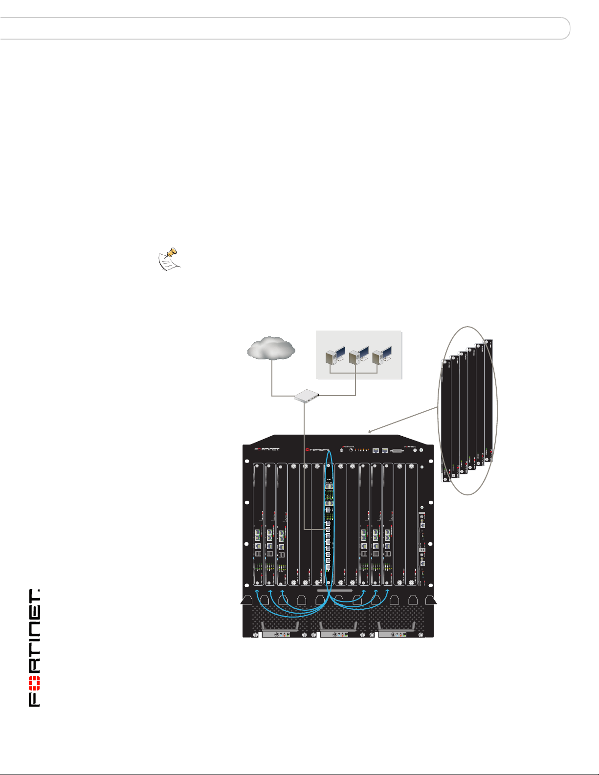
Fabric channel layer-2 link aggregation FortiGate-5140 fabric backplane communication
Distributed 10-gigabit
data communication
on fabric channel 1
Six FortiGate-RTM-XB2
modules installed in RTM
slots 6, 8, 9, 10, 11, and
13 to provide 10-gigabit
fabric interfaces and
NP2 acceleration for each
FortiGate-5001A board
Internal and external
10-gigabit networks
connected to
FortiSwitch-5003A
front panel interface F7
and to fabric channel 1
External switch
VLAN
tagged
traffic
External
Network
Internal Network
Because the FortiGate-5000 boards in a link aggregation configuration operate in
transparent mode, any routing, VPN or NAT requirements should be handed by an
external device (such as a router), before or after the traffic reaches the
FortiSwitch-5003A board.
If the traffic that you are distributing contains VLAN-tagged packets, you must add
the VLAN tags to the FortiSwitch-5003A interfaces and to the trunks that will
handle the VLAN-tagged traffic.
Figure shows a basic link aggregation configuration using a single
FortiSwitch-5003A board. In this configuration the external switch is connected to
the FortiSwitch-5003A F7 front panel interface. The external switch adds VLAN
tags to traffic from the internal and external networks. Packets from the internal
network are tagged as 100 and packets from the external network are tagged as
101.
Note: LInk aggregation does not require FortiGate-RTM-XB2 modules. If the example in
Figure did not include FortiGate-RTM-XB2 modules the configuration steps would be the
same and link aggregation would still function the same way. The only difference is without
the FortiGate-RTM-XB2 modules communication on the fabric channel would be 1Gbps
instead of 10 Gbps.
Figure 14: Fabric channel layer-2 link aggregation configuration
5140SAP
5140
1311975312468101214
FILTER
SERIAL 1 SERIAL 2 ALARM
USER2
USER3
USER1
MINOR
MAJOR
CRITICAL
RESET
5000SM
ETH1
ETH0
10/100
10/100
link/Act
link/Act
ETH0
Service
RESET
STATUS
Hot Swap
12
5000SM
ETH1
ETH0
10/100
10/100
link/Act
link/Act
ETH0
Service
RESET
STATUS
Hot Swap
0
FAN TRAY FAN TRAYFAN TRAY
12
FortiSwitch-5003A and 5003 Fabric and Base Backplane Communications Guide
34 01-30000-85717-20081205
Page 35

FortiGate-5140 fabric backplane communication Fabric channel layer-2 link aggregation
The FortiSwitch-5003A configuration consists of adding a trunk named trunk_6
that aggregates backplane slots 6, 8, 9, 10, 11, and 13:
config switch fabric-channel trunk
edit "trunk_6"
set members "slot-6" "slot-8" "slot-9" "slot-10"
"slot-11" "slot-13"
end
Allow VLAN packets on the FortiSwitch-5003A F7 front panel interface and the
trunk:
config switch fabric-channel interface
edit "f7"
set allowed-vlans 1,100-101
next
edit "trunk_6"
set allowed-vlans 1,100-101
end
The traffic enters and exits the FortiGate-5001A boards using the fabric1
interface. You must add two VLAN interfaces to the fabric1 interface, one for traffic
from the Internal network and one for traffic from the external network. Then you
must add firewall policies for traffic between these VLAN interfaces.
For example, you could name the VLAN interfaces vlan_fab1_100 and
vlan_fab1-101. From the FortiGate-5001A CLI enter:
config system interface
edit vlan_fab1_100
set interface fabric1
set vlanid 100
set vdom root
etc...
next
edit vlan_fab1_101
set interface fabric1
set vlanid 101
set vdom root
etc...
end
Then you can add vlan_fab1_100 to vlan_fab1-101 firewall policies the data
traffic.
Note: On some versions of the FortiGate-5001A firmware, when a FortiGate-5001A board
includes a FortiGate-RTM-XB2 module, the fabric1 and fabric2 interfaces are replaced with
interfaces that are named RTM/1 and RTM/2 to indicate the presence of the
FortiGate-RTM-XB2 module. Configuration settings that include the fabric1 and fabric2
interface names will have to be changed to use the RTM/1 and RTM/2 interface names.
You should also configure the FortiGate-5001A boards to send heartbeat packets
over the fabric1 channel so that the FortiSwitch-5003A board can verify that the
FortiGate-5001A boards are functioning. Each FortiGate-5001A board sends 10
heartbeat packets per second from each fabric interface. The packets are type
255 bridge protocol data unit (BPDU) packets. From the FortiGate-5001A CLI
enter:
config system global
set fortiswitch-heartbeat enable
end
FortiSwitch-5003A and 5003 Fabric and Base Backplane Communications Guide
01-30000-85717-20081205 35
Page 36

Fabric channel layer-2 link aggregation and redundancy FortiGate-5140 fabric backplane communication
You must also enable the FortiSwitch-5003A board to listen for heartbeat packets
on all of the interfaces connected to FortiGate-5001A boards:
config switch fabric-channel physical-port
edit "slot-6"
set heartbeat enable
next
edit "slot-8"
set heartbeat enable
next
edit "slot-9"
set heartbeat enable
next
edit "slot-10"
set heartbeat enable
next
edit "slot-11"
set heartbeat enable
next
edit "slot-13"
set heartbeat enable
end
Fabric channel layer-2 link aggregation and redundancy
In addition to 802.3adstatic mode layer-2 link aggregation and 802.1q VLANs the
FortiSwitch-5003A board also supports 802.1s Multi-Spanning Tree Protocol
(MSTP) for the fabric channels. You can use MSTP to add redundancy to a link
aggregation configuration. Redundancy consists of redundant FortiSwitch-5003A
boards that both distribute traffic to multiple FortiGate-5001A or 5005FA2 boards.
To be able to use redundant FortiSwitch-5003A boards in one chassis you must
configure MSTP to eliminate loops. You can also use MSTP settings to control
traffic flow and create different kinds of redundant configurations:
• An active-passive configuration where the active FortiSwitch-5003A board
receives all traffic and distributes it to the FortiGate-5001A or 5005FA2 boards.
If the active FortiSwitch-5003A board fails, all traffic is diverted to the passive
FortiSwitch-5003A board which takes over distributing traffic to the
FortiGate-5001A or 5005FA2 boards.
• An active-active configuration where both FortiSwitch-5003A boards receive
and distribute traffic. If one of the FortiSwitch-5003A boards fails, all traffic is
diverted to the remaining FortiSwitch-5003A board which takes over
distributing all traffic to the FortiGate-5001A or 5005FA2 boards.
Redundant configurations require a third-party switch that supports MSTP and is
used to connect the FortiSwitch-5003A boards to the networks. You configure
MSTP on the third-party switch and on the FortiSwitch-5003A boards to create
spanning tree instances on all three devices. All three devices must have the
same spanning tree instances. Depending on the requirement, the spanning tree
instances can have different priorities on each device. You can also use the
third-party switch to add and remove VLAN tags from incoming and outgoing
traffic.
FortiSwitch-5003A and 5003 Fabric and Base Backplane Communications Guide
36 01-30000-85717-20081205
Page 37

FortiGate-5140 fabric backplane communication Example active-passive redundant link configuration
The configuration of the spanning tree instances determines whether you create
an active-passive or active-active configuration:
• For an active-passive configuration, you can create one spanning tree
instance on all three devices and give one of the FortiSwitch-5003A boards a
higher priority. This board becomes the active board in the configuration
because spanning tree sends all traffic to the high priority spanning tree
instance. If the active board fails, spanning tree re-directs all traffic to the other
board.
• For an active-active configuration, you create two or more spanning tree
instances on all three devices and give some instances a higher priority on one
FortiSwitch-5003A board and give other instances a higher on the other
FortiSwitch-5003A board. While both FortiSwitch-5003A boards are, the
spanning tree configuration distributes traffic to both boards. If one of the
FortiSwitch-5003A boards fails, spanning tree redirects all of the traffic to the
board that is still operating.
Note: If you have more than one spanning tree instance you can still configure an
active-passive configuration by setting the priorities of all spanning tree instances to be
higher for the same FortiSwitch-5003A board.
In both active-passive or active-active configurations, if one of the
FortiSwitch-5003A boards fails, sessions are temporarily interrupted because the
FortiSwitch-5003A boards do not store session information.
Example active-passive redundant link configuration
Figure 15 shows an example redundant link aggregation configuration. In this
configuration an external switch is connected to two FortiSwitch-5003A front panel
F7 interfaces. The switch adds VLAN tags to traffic from two internal and two
external networks. Packets from each network get different VLAN tags. Packets
from internal networks are tagged as 103 and 104 and packets from the external
networks are tagged as 105 and 106.
To make this an active-passive configuration, the spanning tree instances on the
FortiSwitch-5003A board in slot 1 should have a higher priority than the spanning
tree instances on the FortiSwitch-5003A board in slot 2. The FortiSwitch-5003A
board in slot 1 becomes the root for both spanning tree instances. Because of the
priority settings, MSTP sends all packets to the FortiSwitch-5003A board in slot 1.
If this board fails, MSTP re-directs all packets to the FortiSwitch-5003A board in
slot 2.
For a given spanning tree instance, MSTP directs packets to the device with the
lowest priority value. To give a spanning tree instance a higher priority on a device
you must configure the instance on that device with a lower priority value. The
lower priority value gives the device a higher spanning tree priority for a given
spanning tree instance.
In this example the spanning tree priority values on the FortiSwitch-5003A board
in slot 1 are both set to 4096 and the spanning tree priority values on the
FortiSwitch-5003A board in slot 2 are both set to 40960. So spanning tree directs
all traffic to the FortiSwitch-5003A board in slot 1.
FortiSwitch-5003A and 5003 Fabric and Base Backplane Communications Guide
01-30000-85717-20081205 37
Page 38

Example active-passive redundant link configuration FortiGate-5140 fabric backplane communication
Distributed 10-gigabit
data communication
on fabric channel 1
Distributed 10-gigabit
data communication
on fabric channel 2
Six FortiGate-RTM-XB2
modules installed in RTM
slots 6, 8, 9, 10, 11, and 13 to
provide 10-gigabit
fabric interfaces and
NP2 acceleration for each
FortiGate-5001A board.
Internal and external
10-gigabit networks
connected to
FortiSwitch-5003A
front panel interface F7
and to fabric channels
1 and 2
External Switch
VLAN
Tagged
Traff ic
External Networks
Internal Networks
All of the FortiGate-5001A boards must be operating in transparent mode and all
must have the same configuration. In this redundant configuration, traffic can be
re-directed from one fabric channel to another after a FortiSwitch-5003A fails or if
you change the MSTP configuration. To make sure the FortiGate-5001A boards
can continue to process traffic after a failure or MSTP configuration change you
must add redundant configurations to both fabric interfaces. This means adding 4
VLAN interfaces to each fabric interface (one for each VLAN tag) and configuring
duplicate firewall policies and routing for both sets of VLAN interfaces.
Figure 15: Redundant link aggregation configuration
5140SAP
5140
1311975312468101214
SERIAL 1 SERIAL 2 ALARM
L
2
1
3
R
A
R
R
R
R
O
C
T
O
I
J
E
E
E
E
IN
IT
S
S
S
A
S
R
U
U
U
M
E
M
C
R
External switch configuration
The external switch requires the following configuration settings. Example
commands are shown for an HP procurve 3500yl switch with interfaces A1 and A4
connected to the FortiSwitch-5003A boards. The external switch acts as the root
for spanning tree instance 0.
1 Create an MSTP configuration that includes a name and a revision. For example,
if the name is tree_1 and the revision is 1:
spanning-tree config-name "tree_1"
spanning-tree config-revision 1
FILTER
0
12
5000SM
ETH1
ETH0
10/100
10/100
link/Act
link/Act
ETH0
Service
RESET
STATUS
Hot Swap
12
5000SM
ETH1
ETH0
10/100
10/100
link/Act
link/Act
ETH0
Service
RESET
STATUS
Hot Swap
FAN TRAY FAN TRAYFAN TRAY
38 01-30000-85717-20081205
FortiSwitch-5003A and 5003 Fabric and Base Backplane Communications Guide
Page 39

FortiGate-5140 fabric backplane communication Example active-passive redundant link configuration
2 Configure the switch to add VLAN tag 103 and 104 to packets from the internal
networks and VLAN tag 105 and 106 to packets from the external networks and to
send packets from all of these networks to the FortiSwitch-5003A board.
vlan 103
name "VLAN103"
tagged 6,8,19,A1,A4
exit
vlan 104
name "VLAN104"
tagged 5,7,20,A1,A4
no ip address
exit
vlan 105
name "VLAN105"
tagged 6,8,19,A1,A4
no ip address
exit
vlan 106
name "VLAN106"
tagged 5,7,20,A1,A4
no ip address
exit
3 Add spanning tree instance 3 for packets from the internal networks. Add VLAN
tags 103 and 104 to this spanning tree instance. Set the priority of this spanning
tree instance to 5.
spanning-tree instance 3 vlan 103 104
spanning-tree instance 3 priority 5
4 Add spanning tree instance 5 for packets from the external networks. Add VLAN
tags 105 and 106 to this spanning tree instance. Set the priority of this spanning
tree instance to 5, the same as instance 3.
spanning-tree instance 5 vlan 105 106
spanning-tree instance 5 priority 5
Example configuration for the FortiSwitch-5003A board in slot 1
The FortiSwitch-5003A board in slot 1 requires the following configuration
settings:
1 Disable communication between the FortiSwitch-5003A boards:
config switch fabric-channel physical-port
edit slot-2/1
set status down
end
2 Create an MSTP configuration that includes the same name and revision as was
added to the external switch. For example, if the name is tree_1 and the revision
is 1:
config switch fabric-channel stp settings
set name "tree_1"
set revision 1
end
FortiSwitch-5003A and 5003 Fabric and Base Backplane Communications Guide
01-30000-85717-20081205 39
Page 40

Example active-passive redundant link configuration FortiGate-5140 fabric backplane communication
3 Add two spanning tree instances numbered the same as the instances added to
the switch (3 and 5). Add the VLAN tags to the instances and set their priority
values to 4096:
config switch fabric-channel stp instance
edit 3
set priority 4096
set vlan-range 103-104
next
edit 5
set priority 4096
set vlan-range 105-106
end
Note: The priority values of both spanning tree instances should be lower on the
FortiSwitch-5003A board in slot 1 than on the board in slot 2 so that spanning tree directs
all traffic to the board in slot 1.
4 Add a trunk named trunk_6 that aggregates backplane slots 6, 8, 9, 10, 11, and
13:
config switch fabric-channel trunk
edit "trunk_6"
set members "slot-6" "slot-8" "slot-9" "slot-10"
"slot-11" "slot-13"
end
5 Allow VLAN packets on the FortiSwitch-5003A F7 front panel interface and the
trunk:
config switch fabric-channel interface
edit "f7"
set allowed-vlans 1,103-106
next
edit "trunk_6"
set allowed-vlans 1,103-106
end
6 Enable the FortiSwitch-5003A board to listen for heartbeat packets on all of the
interfaces connected to FortiGate-5001A boards:
config switch fabric-channel physical-port
edit "slot-6"
set heartbeat enable
next
edit "slot-8"
set heartbeat enable
next
edit "slot-9"
set heartbeat enable
next
edit "slot-10"
set heartbeat enable
next
edit "slot-11"
set heartbeat enable
next
edit "slot-13"
set heartbeat enable
end
FortiSwitch-5003A and 5003 Fabric and Base Backplane Communications Guide
40 01-30000-85717-20081205
Page 41

FortiGate-5140 fabric backplane communication Example active-passive redundant link configuration
Verifying the MSTP configuration of the FortiSwitch-5003A board in slot 1
Enter diagnose spanning-tree mst-config fabric-channel to display
the FortiSwitch-5003A fabric channel MSTP configuration.
diagnose spanning-tree mst-config fabric-channel
MST Configuration Identification Information
Unit: Fabric
MST Configuration Name: tree_1
MST Configuration Revision: 1
MST Configuration Digest:
Instance ID Mapped VLANs
____________________________________________________
3 103 104
5 105 106
Enter diagnose spanning-tree instance fabric-channel
<instance_integer> <interface> to display the configuration of a
spanning tree instance for an interface. For example, to display the configuration
of spanning tree instance 3 for the FortiSwitch-5003A F7 interface enter:
diagnose spanning-tree instance fabric-channel 3 f7
d397441fd8666b0abb8f5fab64b9d18a
MST Instance Information, Fabric-Channel:
Instance ID : 3
Mapped VLANs : 103 104
Switch Priority : 4096
Regional Root MAC Address : 003064058f87
Regional Root Priority: 4096
Regional Root Path Cost: 0
Regional Root Port: slot-2/1
Remaining Hops: 20
Port Speed Cost Priority Role State
__________ ______ ________ _________ __________ __________
f7 10G 2000 128 DESIGNATED FORWARDING
FortiSwitch-5003A and 5003 Fabric and Base Backplane Communications Guide
01-30000-85717-20081205 41
Page 42

Example active-passive redundant link configuration FortiGate-5140 fabric backplane communication
Example configuration for the FortiSwitch-5003A board in slot 2
The FortiSwitch-5003A board in slot 2 requires the same configuration settings as
the FortiSwitch-5003A board in slot 1 except that the priority values of both
spanning tree instances is set higher for the FortiSwitch-5003A board in slot 2:
config switch fabric-channel stp instance
edit 3
set priority 40960
set vlan-range 103-104
next
edit 5
set priority 40960
set vlan-range 105-106
end
Note: The priority values of both spanning tree instances should be higher on the
FortiSwitch-5003A board in slot 2 than on the board in slot 1 so that spanning tree directs
all traffic to the board in slot 1.
Verifying the MSTP configuration of the FortiSwitch-5003A board in slot 2
Enter diagnose spanning-tree mst-config fabric-channel to display
the FortiSwitch-5003A fabric channel MSTP configuration.
diagnose spanning-tree mst-config fabric-channel
MST Configuration Identification Information
Unit: Fabric
MST Configuration Name: tree_1
MST Configuration Revision: 1
MST Configuration Digest: 86a2448b88448fb7dbe0f8680e2d0fb5
Instance ID Mapped VLANs
____________________________________________________
3 103 104
5 105 106
To display the configuration of spanning tree instance 5 for the FortiSwitch-5003A
F7 interface enter:
diagnose spanning-tree instance fabric-channel 5 f7
MST Instance Information, Fabric-Channel:
Instance ID : 5
Mapped VLANs : 105 106
Switch Priority : 40960
Regional Root MAC Address : 00306407a1da
Regional Root Priority: 40960
Regional Root Path Cost: 0
Regional Root Port: slot-2/1
Remaining Hops: 20
Port Speed Cost Priority Role State
__________ ______ ________ _________ __________ __________
f7 10G 2000 128 DESIGNATED FORWARDING
FortiSwitch-5003A and 5003 Fabric and Base Backplane Communications Guide
42 01-30000-85717-20081205
Page 43

FortiGate-5140 fabric backplane communication Example active-passive redundant link configuration
Example FortiGate-5001A configuration
All of the FortiGate-5001A boards must be operating in transparent mode and all
must have the same configuration.
The spanning tree instances can send traffic to fabric channel 1 or fabric channel
2. As a result, traffic can enter and exit the FortiGate-5001A boards using the
fabric1 interface or the fabric2 interface. So you should create redundant
configurations for each fabric interface. For each fabric interface you must add
four VLAN interfaces, two for traffic from both Internal networks and two for traffic
from both external networks. Then for each fabric interface you must add firewall
policies for traffic between the four VLAN interfaces.
For example, for the fabric1 interface you could name the VLAN interfaces
vlan_fab1_103, vlan_fab1-104, vlan_fab1_105, and vlan_fab1-106.
From the FortiGate-5001A CLI enter:
config system interface
edit vlan_fab1_103
set interface fabric1
set vlanid 103
set vdom root
etc...
next
edit vlan_fab1_104
set interface fabric1
set vlanid 104
set vdom root
etc...
edit vlan_fab1_105
set interface fabric1
set vlanid 105
set vdom root
etc...
next
edit vlan_fab1_106
set interface fabric1
set vlanid 106
set vdom root
etc...
end
For the fabric2 interface you could name the VLAN interfaces vlan_fab2_103,
vlan_fab2-104, vlan_fab2_105, and vlan_fab2-106. From the
FortiGate-5001A CLI enter:
config system interface
edit vlan_fab2_103
set interface fabric2
set vlanid 103
set vdom root
etc...
next
edit vlan_fab2_104
set interface fabric2
set vlanid 104
set vdom root
etc...
FortiSwitch-5003A and 5003 Fabric and Base Backplane Communications Guide
01-30000-85717-20081205 43
Page 44

Example active-active redundant link configuration FortiGate-5140 fabric backplane communication
edit vlan_fab2_105
set interface fabric2
set vlanid 105
set vdom root
etc...
next
edit vlan_fab2_106
set interface fabric2
set vlanid 106
set vdom root
etc...
end
You should also configure the FortiGate-5001A boards to send heartbeat packets
over the fabric1 and fabric2 channels so that the FortiSwitch-5003A board can
verify that the FortiGate-5001A boards are functioning. Each FortiGate-5001A
board sends 10 heartbeat packets per second from each fabric interface. The
packets are type 255 bridge protocol data unit (BPDU) packets. From the
FortiGate-5001A CLI enter:
config system global
set fortiswitch-heartbeat enable
end
Example active-active redundant link configuration
You can make the previous example an active-active redundant link configuration
that sends all traffic from the internal networks to one FortiSwitch-5003A board
and all traffic from the external networks to the other FortiSwitch-5003A board by
changing the priorities of the spanning tree instances added to the
FortiSwitch-5003A boards. No other configuration changes are required.
To send all traffic from the internal networks to the FortiSwitch-5003A board in
slot 1 configure the spanning tree instances on this board with a lower priority
value for instance 3 which is used for VLAN 103 and 104 packets.
config switch fabric-channel stp instance
edit 3
set priority 4096
set vlan-range 103-104
next
edit 5
set priority 40960
set vlan-range 105-106
end
To send all traffic from the external networks to the FortiSwitch-5003A board in
slot 2 configure the spanning tree instances on this board with a lower priority
value for instance 5 which is used for VLAN 105 and 106 packets.
config switch fabric-channel stp instance
edit 3
set priority 40960
set vlan-range 103-104
next
FortiSwitch-5003A and 5003 Fabric and Base Backplane Communications Guide
44 01-30000-85717-20081205
Page 45

FortiGate-5140 fabric backplane communication Example active-active redundant link configuration
edit 5
set priority 4096
set vlan-range 105-106
end
Verifying the spanning tree configuration of the FortiSwitch-5003A board in slot 1
To display the configuration of spanning tree instance 3 for the FortiSwitch-5003A
F7 interface enter:
diagnose spanning-tree instance fabric-channel 3 f7
MST Instance Information, Fabric-Channel:
Instance ID : 3
Mapped VLANs : 103 104
Switch Priority : 4096
Regional Root MAC Address : 00306407a1da
Regional Root Priority: 4096
Regional Root Path Cost: 0
Regional Root Port: slot-2/1
Remaining Hops: 20
Port Speed Cost Priority Role State
__________ ______ ________ _________ __________ __________
f7 10G 2000 128 DESIGNATED FORWARDING
FortiSwitch-5003A and 5003 Fabric and Base Backplane Communications Guide
01-30000-85717-20081205 45
Page 46

Example active-active redundant link configuration FortiGate-5140 fabric backplane communication
FortiSwitch-5003A and 5003 Fabric and Base Backplane Communications Guide
46 01-30000-85717-20081205
Page 47

FortiGate-5050 fabric backplane communication
FortiGate-5050 fabric backplane
communication
The FortiGate-5505 chassis has two fabric backplane Ethernet channels that can
operate at 1 Gbps or 10 Gbps. Available connections to these channels vary by
hub/switch slot number.
• Hub/switch slot 1 can connect to the first fabric backplane channel (channel 1),
and thereby all other chassis slots, except hub/switch slot 2.
• Hub/switch Slot 2 can connect the to the second fabric backplane channel
(channel 2), and thereby all other chassis slots, except hub/switch slot 1.
• Other slots can connect to either or both channels, but only directly reach
hub/switch slot 1 or hub/switch slot 2. Connections to other slots through the
fabric backplane channels must pass through hub/switch slot 1 or hub/switch
slot 2.
Note: For more information on chassis architecture, see ATCA (Advanced Telecom
Computing Architecture) specifications.
Because of the fabric backplane dual star topology, connecting to or through the
fabric backplane requires FortiSwitch-5003A boards installed in hub/switch slot 1,
hub/switch slot 2, or both. FortiSwitch-5003A front panel fabric interfaces can also
connect the chassis fabric backplane channels to external devices, such as a
management computer, the network, or the fabric backplane of another chassis.
Note: FortiSwitch-5003 boards do not support fabric backplane switching.
FortiGate-5001A boards and FortiGate-5005FA2 boards can connect to the fabric
backplane at 1 Gbps. With the addition of a FortiGate-RTM-XB2 modules,
FortiSwitch-5001A boards can also connect to the fabric backplane at 10 Gbps.
The FortiGate-5001SX board and FortiGate-5001FA2 board do not include fabric
backplane interfaces.
Table 11: Names of fabric backplane interfaces by FortiGate model
Model Name of fabric backplane
interface 1 (to slot 1)
FortiGate-5001A fabric1 fabric2
FortiGate-5005FA2 fabric1 fabric2
FortiGate-5001FA2 N/A N/A
FortiGate-5001SX N/A N/A
Name of fabric backplane
interface 2 (to slot 2)
FortiSwitch-5003A and 5003 Fabric and Base Backplane Communications Guide
01-30000-85717-20081205 47
Page 48

Fabric gigabit switching within a chassis FortiGate-5050 fabric backplane communication
1
2
2
3
4
5
SMC
1
SMC
POWER
Fabric channel 2
data communication
This section describes:
• Fabric gigabit switching within a chassis
• Fabric channel connections between FortiSwitch-5003A boards
• Fabric gigabit switching between chassis
• Fabric gigabit switching to the network
• Fabric 10-gigabit switching within a chassis
• Fabric channel layer-2 link aggregation
• Fabric channel layer-2 link aggregation and redundancy
• Example active-passive redundant link configuration
• Example active-active redundant link configuration
Fabric gigabit switching within a chassis
You can use FortiSwitch-5003A fabric channel switching for communication
between the fabric backplane interfaces of FortiGate-5001A or 5005FA2 boards
installed in a FortiGate-5050 chassis.
Figure 16 shows a FortiGate-5050 chassis with a FortiSwitch-5003A board in
hub/switch slot 2, and FortiGate-5001A boards in slots 3, 4, and 5. In this
configuration the FortiSwitch-5003A board provides 1-gigabit fabric backplane
switching for the FortiGate-5001A fabric2 interfaces. The FortiSwitch-5003A
boards operate as layer-2 switches and the FortiGate-5001A boards operate as
typical standalone FortiGate units.
The chassis can be connected to the network using any of the FortiGate-5001A
front panel interfaces. You can also connect FortiSwitch-5003A front panel fabric
interfaces to the network. You can also install FortiGate AMC modules in the
FortiGate-5001A boards and connect the network to the AMC front panel
interfaces. The AMC modules and the network connections are not shown in
Figure 16.
Figure 16: FortiGate-5050 fabric channel 2 data communication
5000SM
10/100
ETH0
Service
link/Act
ETH1
STATUS
10/100
RESET
ETH0
link/Act
5050SAP
SERIAL
Hot Swap
1
ALARM
5000SM
10/100
ETH0
Service
link/Act
ETH1
SERIAL
2
STATUS
10/100
ETH0
link/Act
Hot Swap
RESET
48 01-30000-85717-20081205
FortiSwitch-5003A and 5003 Fabric and Base Backplane Communications Guide
Page 49

FortiGate-5050 fabric backplane communication Fabric gigabit switching within a chassis
For the FortiGate-5001A boards to use the fabric channel 2 for data
communication you must show backplane interfaces on the FortiGate-5001A
web-based manager and then configure firewall polices and routing for the fabric2
interfaces.
If the data traffic contains VLAN-tagged packets, you must add the VLAN tags to
the FortiSwitch-5003A interfaces that will handle the VLAN-tagged traffic. For
example, to allow VLAN tag 34 on slot 5 from the FortiSwitch-5003A CLI enter:
config switch fabric-channel interface
edit "slot-5"
set allowed-vlans 1,34
end
For more information about the FortiSwitch-5003A CLI, see “FortiSwitch-5003A
CLI reference” on page 89.
Figure 17 shows a FortiGate-5050 chassis with FortiSwitch-5003A boards in
hub/switch slots 1 and 2 and FortiGate-5001A boards in slots 3, 4, and 5. In this
configuration the FortiSwitch-5003A boards are operating as layer-2 switches for
fabric channels 1 and 2 and the FortiGate-5001A boards are operating as typical
standalone FortiGate units. The FortiGate-5001A boards can use fabric channels
1 and 2 for data communication among the FortiGate boards.
The chassis can be connected to the network using any of the FortiGate-5001A
front panel interfaces. You can also connect FortiSwitch-5003A front panel fabric
interfaces to the network. You can also install FortiGate AMC modules in the
FortiGate-5001A boards and connect the network to the AMC front panel
interfaces. The AMC modules and the network connections are not shown in
Figure 17.
Figure 17: FortiGate-5050 fabric channel 1 and 2 data communication
Fabric channel 1
data communication
5
4
3
2
1
5000SM
10/100
SMC
ETH0
link/Act
ETH1
10/100
ETH0
link/Act
2
Service
STATUS
RESET
5050SAP
SERIAL
Hot Swap
1
ALARM
5000SM
10/100
link/Act
ETH1
SERIAL
10/100
2
ETH0
link/Act
Fabric channel 2
data communication
POWER
ETH0
Service
SMC
STATUS
Hot Swap
RESET
1
For the FortiGate-5001A boards to use the fabric channels 1 and 2 for data
communication you must show backplane interfaces on the FortiGate-5001A
web-based manager and then configure firewall polices and routing for the fabric1
and fabric2 interfaces.
FortiSwitch-5003A and 5003 Fabric and Base Backplane Communications Guide
01-30000-85717-20081205 49
Page 50

Fabric channel connections between FortiSwitch-5003A boards FortiGate-5050 fabric backplane communication
If the data traffic contains VLAN-tagged packets, you must add the VLAN tags to
the FortiSwitch-5003A interfaces that will handle the VLAN-tagged traffic. For
example, to allow VLAN tags 200 to 205 on slots 3, 4, and 5 from the
FortiSwitch-5003A CLI enter:
config switch fabric-channel interface
edit "slot-3"
set allowed-vlans 1,200-205
next
edit "slot-4"
set allowed-vlans 1,200-205
next
edit "slot-5"
set allowed-vlans 1,200-205
end
Fabric channel connections between FortiSwitch-5003A boards
When two FortiSwitch-5003A boards are installed in a single chassis their fabric
channels are connected together. This means there is a data connection between
fabric channel 1 and fabric channel 2. Unless you are going to use this connection
you should disable it.
If one or more of the FortiGate-5001A or 5005FA2 boards are operating in
transparent mode, the connection between the fabric channels can cause looping.
If you have one or more FortiGate-5001A or 5005FA2 boards operating in
transparent mode with two FortiSwitch-5003A boards in the same chassis you
must disable communication between the FortiSwitch-5003A boards.
The fabric channel connection between the FortiSwitch-5003A boards uses an
internal FortiSwitch-5003A interface called slot-2/1. To disable the fabric channel
connection between two FortiSwitch-5003A boards you should set the status of
slot-2/1 to down for one of the boards. Connect to the CLI of one of the
FortiSwitch-5003A boards and enter the following command:
config switch fabric-channel physical-port
edit slot-2/1
set status down
end
Fabric gigabit switching between chassis
You can use the FortiSwitch-5003A front panel fabric interfaces to provide
10-gigabit data communications between the fabric channels of any combination
of FortiGate-5050 and FortiGate-5140 chassis.
Note: Its not required, but in most cases you would connect the same fabric channels
together. That is you would connect fabric channel 1 on one chassis to fabric channel 1 on
another. Usually you would not connect fabric channel 1 on one chassis to fabric channel 2
on another chassis. Also, you would usually not connect a base channel from one chassis
to a fabric channel on another chassis. You should be careful of looping when connecting
chassis together if some of the FortiGate boards in the chassis are operating in transparent
mode.
FortiSwitch-5003A and 5003 Fabric and Base Backplane Communications Guide
50 01-30000-85717-20081205
Page 51

FortiGate-5050 fabric backplane communication Fabric gigabit switching between chassis
Fabric channel 2
10-figabit data
ccommunication
between 2 chassis
1
2
2
3
4
5
SMC
1
SMC
POWER
1
2
2
3
4
5
SMC
1
SMC
POWER
Figure 18 shows data communication between two FortiGate-5050 chassis using
fabric channel 2. The top chassis in the figure contains a FortiSwitch-5003A board
in hub/switch slot 2 and three FortiGate-5001A boards. The bottom chassis
contains a FortiSwitch-5003A board also in hub/switch slot 2 and two
FortiGate-5005FA2 boards. The chassis are connected together using their
respective FortiSwitch-5003A F1 front panel interfaces.
In this configuration the FortiSwitch-5003A boards are operating as layer-2
switches for fabric channel 2 and the FortiGate-5001A and 5005FA2 boards are
operating as typical standalone FortiGate units.
The chassis can be connected to the network using any of the FortiGate front
panel interfaces. You can also connect FortiSwitch-5003A front panel fabric
interfaces to the network. You can also install FortiGate AMC modules in the
FortiGate-5001A boards and connect networks to the AMC front panel interfaces.
The AMC modules and the network connections are not shown in Figure 18.
Figure 18: Fabric channel 2 data communication between two FortiGate-5050
chassis
5000SM
10/100
ETH0
Service
link/Act
ETH1
STATUS
10/100
RESET
ETH0
link/Act
ACT
LINK
BASE
ACT
FABRIC
LINK
CONSOLE
ACT
LINK
BASE
ACT
FABRIC
LINK
CONSOLE
5000SM
10/100
ETH0
Service
link/Act
ETH1
STATUS
10/100
RESET
ETH0
link/Act
For the FortiGate-5001A and 50005FA2 boards to use fabric channel 2 for data
communication you must show backplane interfaces on the FortiGate web-based
manager and then configure firewall polices and routing for the fabric2 interfaces.
Hot Swap
USB USB
OOS ACC STATUS
USB USB
OOS ACC STATUS
Hot Swap
SERIAL
SERIAL
1
1
5050SAP
5050SAP
ALARM
3 412 56
3 412 56
ALARM
5000SM
10/100
ETH0
Service
link/Act
ETH1
SERIAL
2
SERIAL
2
10/100
ETH0
link/Act
78
IPM
78
IPM
5000SM
10/100
link/Act
ETH1
10/100
ETH0
link/Act
STATUS
Hot Swap
RESET
ETH0
Service
STATUS
Hot Swap
RESET
FortiSwitch-5003A and 5003 Fabric and Base Backplane Communications Guide
01-30000-85717-20081205 51
Page 52

Fabric gigabit switching to the network FortiGate-5050 fabric backplane communication
If the data traffic contains VLAN-tagged packets, you must add the VLAN tags to
the FortiSwitch-5003A interfaces that will handle the VLAN-tagged traffic. For
example, to allow VLAN tags 201 to 210 on slots 3, 4, and 5 and the F1 front panel
interface, from the FortiSwitch-5003A CLI enter:
config switch fabric-channel interface
edit "slot-3"
set allowed-vlans 1,201-210
next
edit "slot-4"
set allowed-vlans 1,201-210
next
edit "slot-5"
set allowed-vlans 1,201-210
next
edit "f1"
set allowed-vlans 1,201-210
end
Fabric gigabit switching to the network
You can use the FortiSwitch-5003A fabric front panel interfaces to connect the
fabric channel of a chassis to your network. Most often you would do this for data
communication between the network and a fabric channel. For a simple 10-gigabit
connection from your network to a fabric channel you can connect your network
directly to a FortiSwitch-5003A fabric channel front panel interface. This
connection provides data communication to the fabric1 or fabric2 interfaces of the
FortiGate-5000 boards installed in the chassis.
Figure 19 shows a FortiGate-5050 chassis containing two FortiSwitch-5003A
boards and three FortiGate-5001A boards. The chassis is connected to internal
and an external networks using FortiSwitch-5003A front panel fabric interfaces:
• The internal network is connected to fabric channel 2 using the F7 front panel
interface of the FortiSwitch-5003A board in hub/switch slot 2
• The external network is connected to fabric channel 1 using the F1 front panel
interface of the FortiSwitch-5003A board in hub/switch slot 1
In this configuration the FortiSwitch-5003A boards are operating as layer-2
switches and the FortiGate-5001A boards are operating as standalone FortiGate
units.
The chassis can also be connected to the network using any of the FortiGate front
panel interfaces. You can also install FortiGate AMC modules in the
FortiGate-5001A boards and connect networks to the AMC front panel interfaces.
The AMC modules and network connections to the AMC modules and FortiGate
boards are not shown in Figure 19.
FortiSwitch-5003A and 5003 Fabric and Base Backplane Communications Guide
52 01-30000-85717-20081205
Page 53

FortiGate-5050 fabric backplane communication Fabric gigabit switching to the network
Figure 19: Fabric channel 2 connected to an internal network and fabric channel 1
connected to an external network
Internal Network
Internal network connected to the F7
front panel fabric interface
to connect to fabric channel 2
5
Fabric channel 1
Data
Communication
4
3
2
POWER
Fabric channel 2
Data
Communication
1
5000SM
10/100
SMC
ETH0
Service
link/Act
ETH1
STATUS
10/100
RESET
ETH0
link/Act
2
5050SAP
SERIAL
Hot Swap
1
ALARM
5000SM
10/100
ETH0
link/Act
ETH1
SERIAL
10/100
2
ETH0
link/Act
SMC
Service
STATUS
Hot Swap
RESET
1
External network connected to the F1
front panel fabric interface
to connect to fabric channel 1
External
Network
If you have two FortiSwitch-5003A boards installed in a chassis you may need to
block communication between fabric channel 1 and fabric channel 2. See “Fabric
channel connections between FortiSwitch-5003A boards” on page 50 for more
information.
For the FortiGate-5001A boards to use the fabric channels for data
communication you must show backplane interfaces on the FortiGate web-based
manager and then configure firewall polices and routing for the fabric1 and fabric2
interfaces.
If the data traffic contains VLAN-tagged packets, you must add the VLAN tags to
the FortiSwitch-5003A interfaces that will handle the VLAN-tagged traffic. For
example, to allow VLAN tags 80 to 90 on slots 3, 4, and 5 and the F7 front panel
interface, from the FortiSwitch-5003A CLI enter:
config switch fabric-channel interface
edit "slot-3"
set allowed-vlans 1,80-90
next
edit "slot-4"
set allowed-vlans 1,80-90
next
edit "slot-5"
set allowed-vlans 1,80-90
next
edit "f7"
set allowed-vlans 1,80-90
end
FortiSwitch-5003A and 5003 Fabric and Base Backplane Communications Guide
01-30000-85717-20081205 53
Page 54

Fabric 10-gigabit switching within a chassis FortiGate-5050 fabric backplane communication
Fabric 10-gigabit switching within a chassis
All of the FortiSwitch-5003A fabric front panel interfaces are 10-gigabit interfaces
and the FortiSwitch-5003A board supports 10-gigabit communication across the
fabric backplane channels. The FortiGate-5001A board also supports 10-gigabit
communication on the fabric backplane with the addition of a FortiGate-RTM-XB2
module. You require one FortiGate-RTM-XB2 module for each FortiGate-5001A
board. The FortiGate-RTM-XB2 module must be installed in the chassis rear
transition module (RTM) slot that corresponds to the front panel slot containing the
FortiGate-5001A board. For example, if you install a FortiGate-5001A board in slot
3 you must also install a FortiGateRTM-XB2 module in RTM slot 3. The RTM slots
are at the back of the FortiGate-5050 chassis.
One FortiGate-RTM-XB2 module provides 10-gigabit connections to both fabric
channels. The FortiGate-RTM-XB2 also provides NP2 packet acceleration for
both fabric channels. To effectively use NP2 acceleration, packets must be
received by the FortiGate-5001A board on one fabric channel and must exit from
the FortiGate-5001A board on the same fabric channel or on the other fabric
channel. See the FortiGate-RTM-XB2 System Guide for more information about
the FortiGate-RTM-XB2.
Note: A single FortiSwitch-5003A can provide simultaneous 10 Gbps connections to
FortiGate-5001A boards with FortiGate-RTM-XB2 modules, 1 Gbps connections to
FortiGate-5001A boards, and 1 Gbps connections to FortiGate-5005FA2 boards.
Figure 20 shows a FortiGate-5050 chassis containing two FortiSwitch-5003A
boards and one FortiGate-5001A board. Using these components this chassis
supplies 10-gigabit connectivity between the external and internal networks. The
external network is connected to the F1 10-gigabit front panel interface of the
FortiSwitch-5003A board in slot 1, which connects the external network to fabric
channel 1. The internal network is connected to the F7 10-gigabit front panel
interface of the FortiSwitch-5003A board in slot 2, which connects the internal
network to fabric channel 2.
10-gigabit traffic from the external network enters the F1 10-gigabit
FortiSwitch-5003A front panel interface, passes through the FortiSwitch-5003A
board and through the FortiGate-RTM-XB2 module to the fabric1 interface of the
FortiGate-5001A board. Traffic accepted at the fabric1 interface is processed by
the FortiGate-5001A board. Traffic destined for the internal network exits the
fabric2 interface of the FortiGate-5001A board, passes through the
FortiGate-RTM-XB2 module and through the FortiSwitch-5003A board and exits
the F7 10-gigabit FortiSwitch-5003A front panel interface and is received by the
internal network.
FortiSwitch-5003A and 5003 Fabric and Base Backplane Communications Guide
54 01-30000-85717-20081205
Page 55

FortiGate-5050 fabric backplane communication Fabric 10-gigabit switching within a chassis
Fabric Channel 2
10-gigabit Data
Communication
FortiGate-RTM-XB2
module installed in RTM
slot 3 provides two
10-gigabit fabric channels
and NP2 acceleration for
the FortiGate-5001A board
FortiGate-5001A Board
Installed in FortiGate-5050
front panel slot 3
Fabric Channel 1
10 Gigabit Data
Communication
Internal 10-gigabit
Network Connected
to Fabric Channel 2
External 10-gigabit
Network Connected
to Fabric Channel 1
Internal Network
External
Network
Figure 20: Example 10-gigabit connection between internal and external networks
5
4
3
2
1
5000SM
10/100
SMC
ETH0
Service
link/Act
ETH1
STATUS
10/100
RESET
ETH0
link/Act
2
5050SAP
SERIAL
Hot Swap
1
ALARM
5000SM
10/100
link/Act
ETH1
SERIAL
10/100
2
ETH0
link/Act
POWER
SMC
ETH0
Service
STATUS
Hot Swap
RESET
1
The configuration shown in Figure 20 requires no configuration changes to the
FortiSwitch-5003A boards except to disable communication between the
FortiSwitch-5003A boards (if required, see “Fabric channel connections between
FortiSwitch-5003A boards” on page 50).
On the FortiGate-5001A board, to allow traffic to pass between the internal and
external networks, the FortiGate-5001A board would operate in NAT/Route mode
and you must configure firewall policies and routing for the fabric1 and fabric2
interfaces. No configuration changes are required to use the FortiGate-RTM-XB2
module. NP2 acceleration is automatically applied to traffic passing between the
internal and external networks by the FortiGate-RTM-XB2 module.
Note: On some versions of the FortiGate-5001A firmware, when a FortiGate-5001A board
starts up with a FortiGate-RTM-XB2 module installed, the fabric1 and fabric2 interfaces are
replaced with interfaces that are named RTM/1 and RTM/2 to indicate the presence of the
FortiGate-RTM-XB2 module. Configuration settings that include the fabric1 and fabric2
interface names will have to be changed to use the RTM/1 and RTM/2 interface names.
If the data traffic contains VLAN-tagged packets, you must add the VLAN tags to
the FortiSwitch-5003A interfaces that will handle the VLAN-tagged traffic. For
example, to allow VLAN tags 80 to 90 on slots 1 and the F7 front panel interface,
from the FortiSwitch-5003A CLI enter:
config switch fabric-channel interface
edit "slot-1"
set allowed-vlans 1,80-90
next
edit "f7"
set allowed-vlans 1,80-90
end
FortiSwitch-5003A and 5003 Fabric and Base Backplane Communications Guide
01-30000-85717-20081205 55
Page 56

Fabric channel layer-2 link aggregation FortiGate-5050 fabric backplane communication
Fabric channel layer-2 link aggregation
FortiSwitch-5003A boards support 802.3ad static mode layer-2 link aggregation
and 802.1q VLANs for the fabric channels. You can use these features to
configure link aggregation to distribute traffic to multiple FortiGate-5001A or
5005FA2 boards. Link aggregation configurations also support IPv6 traffic and
traffic with jumbo frames up to 16 kbytes.
You can use link aggregation to increase the bandwidth capacity of a
FortiGate-5000 configuration by distributing network traffic among multiple
FortiGate-5001A or 5005FA2 boards. Adding a new FortiGate-5000 board to a
trunk results in an almost linear increase in performance. Link aggregation is
configured and functions the same way for 1-gigabit and 10-gigabit fabric
backplane networks. You can configure 1-gigabit configurations with FortiGate5001A or 5005FA2 boards. You can configure 10-gigabit configurations with
FortiGate-5001A boards combined with FortiGate-RTM-XB2 modules. FortiGateRTM-XB2 modules also increase performance by added NP2 acceleration to the
configuration.
You configure link aggregation by adding FortiSwitch-5003A interfaces to a link
aggregation trunk. The FortiSwitch-5003A board uses a hash algorithm based on
source and destination IP addresses to distribute sessions to the interfaces added
to the trunk. Each interface in the trunk usually corresponds to a slot in the chassis
in which a FortiGate-5001A or 5005FA2 board is installed. You can also include
FortiSwitch-5003A front panel interfaces in a trunk and distribute sessions to
FortiGate-5000 boards installed in multiple chassis.
Note: The FortiSwitch-5003A board does not support Link Aggregation Control Protocol
(LACP). LACP is also called 802.3ad dynamic mode layer-2 link aggregation.
You can add up to 8 interfaces to a trunk to distribute sessions among up to 8
FortiGate-5000 boards. You can also add multiple trunks to a single
FortiSwitch-5003A board. The total number of FortiGate-5000 boards in a trunk is
limited by the amount of bandwidth you are processing and the capacity of the
FortiSwitch-5003A board. Fortinet does not support mixing FortiGate-5001A and
5005FA2 boards in the same trunk.
If you add a FortiGate-5000 board to a trunk, or if you remove a FortiGate-5000
board from a trunk the link aggregation hash algorithm recalculates the session
distribution. If the FortiSwitch-5003A system is processing traffic when you add or
remove a FortiGate-5000 board, after sessions are redistributed the
FortiGate-5000 boards in the trunk will not necessarily continue to process the
same sessions. The same happens if a FortiGate-5000 board in a trunk fails. The
FortiSwitch-5003A system does not maintain a session table, so changes to a
trunk can result in communication being temporarily interrupted. As a result you
should only add or remove FortiGate-5000 boards from a trunk during off-peak
hours.
The FortiGate-5000 boards in a trunk must operate in transparent mode. All the
FortiGate-5000 boards in a trunk are managed separately and all must have the
same configuration. You can use the FortiManager system to maintain the same
configuration on the FortiGate-5000 boards.
FortiSwitch-5003A and 5003 Fabric and Base Backplane Communications Guide
56 01-30000-85717-20081205
Page 57

FortiGate-5050 fabric backplane communication Fabric channel layer-2 link aggregation
Note: Due to the way the hash algorithm works, FortiGate-5000 boards in the lower
numbered chassis slots in a trunk may receive more traffic. The order of the interfaces in
the trunk does not matter, the numerically lowest slots will always be the ones to receive
more traffic if the number of interfaces in the trunk is not a power of 2.
Because the FortiGate-5000 boards in a link aggregation configuration operate in
transparent mode, any routing, VPN or NAT requirements should be handed by
an external device (such as a router), before or after the traffic reaches the
FortiSwitch-5003A board.
If the traffic that you are distributing contains VLAN-tagged packets, you must add
the VLAN tags to the FortiSwitch-5003A interfaces and to the trunks that will
handle the VLAN-tagged traffic.
Figure 21 shows a basic link aggregation configuration using a single
FortiSwitch-5003A board. In this configuration the external switch is connected to
the FortiSwitch-5003A F5 front panel interface. The external switch adds VLAN
tags to traffic from the internal and external networks. Packets from the internal
network are tagged as 100 and packets from the external network are tagged as
101.
Note: LInk aggregation does not require FortiGate-RTM-XB2 modules. If the example in
Figure 21 did not include FortiGate-RTM-XB2 modules the configuration steps would be the
same and link aggregation would still function the same way. The only difference is
communication on the fabric channel would be 1 Gbps instead of 10 Gbps without the
FortiGate-RTM-XB2 modules.
Figure 21: Fabric channel layer-2 link aggregation configuration
External
Internal Network
Network
Internal and external
10-gigabit networks
connected to
FortiSwitch-5003A
front panel interface F5
and to fabric channel 2
5
4
3
2
1
5000SM
10/100
SMC
ETH0
Service
link/Act
ETH1
10/100
ETH0
link/Act
2
SERIAL
STATUS
Hot Swap
RESET
5050SAP
1
External switch
ALARM
VLAN
tagged
traffic
SERIAL
2
POWER
Distributed 10-gigabit
data communication
on fabric channel 2
5000SM
10/100
ETH0
link/Act
ETH1
10/100
ETH0
link/Act
SMC
Service
STATUS
Hot Swap
RESET
1
Three FortiGate-RTM-XB2
modules installed in RTM
slots 3, 4, and 5 to
provide 10-gigabit
fabric interfaces and
NP2 acceleration for each
FortiGate-5001A board.
FortiSwitch-5003A and 5003 Fabric and Base Backplane Communications Guide
01-30000-85717-20081205 57
Page 58

Fabric channel layer-2 link aggregation FortiGate-5050 fabric backplane communication
The FortiSwitch-5003A configuration consists of adding a trunk named
trunk_345 that aggregates backplane slots 3, 4, and 5:
config switch fabric-channel trunk
edit "trunk_345"
set members "slot-3" "slot-4" "slot-5"
end
Allow VLAN packets on the FortiSwitch-5003A F5 front panel interface and the
trunk:
config switch fabric-channel interface
edit "f5"
set allowed-vlans 1,100-101
next
edit "trunk_345"
set allowed-vlans 1,100-101
end
The traffic enters and exits the FortiGate-5001A boards using the fabric2
interface. You must add two VLAN interfaces to the fabric2 interface, one for traffic
from the Internal network and one for traffic from the external network. Then you
must add firewall policies for traffic between these VLAN interfaces.
For example, you could name the VLAN interfaces vlan_fab2_100 and
vlan_fab2-101. From the FortiGate-5001A CLI enter:
config system interface
edit vlan_fab2_100
set interface fabric2
set vlanid 100
set vdom root
etc...
next
edit vlan_fab2_101
set interface fabric2
set vlanid 101
set vdom root
etc...
end
Then you can add vlan_fab2_100 to vlan_fab2-101 firewall policies the data
traffic.
Note: On some versions of the FortiGate-5001A firmware, when a FortiGate-5001A board
includes a FortiGate-RTM-XB2 module, the fabric1 and fabric2 interfaces are replaced with
interfaces that are named RTM/1 and RTM/2 to indicate the presence of the
FortiGate-RTM-XB2 module. Configuration settings that include the fabric1 and fabric2
interface names will have to be changed to use the RTM/1 and RTM/2 interface names.
You should also configure the FortiGate-5001A boards to send heartbeat packets
over the fabric1 channel so that the FortiSwitch-5003A board can verify that the
FortiGate-5001A boards are functioning. Each FortiGate-5001A board sends 10
heartbeat packets per second from each fabric interface. The packets are type
255 bridge protocol data unit (BPDU) packets. From the FortiGate-5001A CLI
enter:
config system global
set fortiswitch-heartbeat enable
end
FortiSwitch-5003A and 5003 Fabric and Base Backplane Communications Guide
58 01-30000-85717-20081205
Page 59

FortiGate-5050 fabric backplane communication Fabric channel layer-2 link aggregation and redundancy
You must also enable the FortiSwitch-5003A board to listen for heartbeat packets
on all of the interfaces connected to FortiGate-5001A boards:
config switch fabric-channel physical-port
edit "slot-3"
set heartbeat enable
next
edit "slot-4"
set heartbeat enable
next
edit "slot-5"
set heartbeat enable
end
Fabric channel layer-2 link aggregation and redundancy
In addition to 802.3ad static mode layer-2 link aggregation and 802.1q VLANs the
FortiSwitch-5003A board also supports 802.1s Multi-Spanning Tree Protocol
(MSTP) for the fabric channels. You can use MSTP to add redundancy to a link
aggregation configuration. Redundancy consists of redundant FortiSwitch-5003A
boards that both distribute traffic to multiple FortiGate-5001A or 5005FA2 boards.
To be able to use redundant FortiSwitch-5003A boards in one chassis you must
configure MSTP to eliminate loops. You can also use MSTP settings to control
traffic flow and create different kinds of redundant configurations:
• An active-passive configuration where the active FortiSwitch-5003A board
receives all traffic and distributes it to the FortiGate-5001A or 5005FA2 boards.
If the active FortiSwitch-5003A board fails, all traffic is diverted to the passive
FortiSwitch-5003A board which takes over distributing traffic to the FortiGate5001A or 5005FA2 boards.
• An active-active configuration where both FortiSwitch-5003A boards receive
and distribute traffic. If one of the FortiSwitch-5003A boards fails, all traffic is
diverted to the remaining FortiSwitch-5003A board which takes over
distributing all traffic to the FortiGate-5001A or 5005FA2 boards.
Redundant configurations require a third-party switch that supports MSTP and is
used to connect the FortiSwitch-5003A boards to the networks. You configure
MSTP on the third-party switch and on the FortiSwitch-5003A boards to create a
spanning tree region consisting of spanning tree instances on all three devices. All
three devices must have the same spanning tree instances. Depending on the
requirement, the spanning tree instances can have different priorities on each
device. You can also use the third-party switch to add and remove VLAN tags
from incoming and outgoing traffic.
The configuration of the spanning tree instances on each device determines
whether you create an active-passive or active-active configuration:
• For an active-passive configuration, you can create one spanning tree
instance on all three devices and give one of the FortiSwitch-5003A boards a
higher priority. This board becomes the active board in the configuration
because spanning tree sends all traffic to the high priority spanning tree
instance. If the active board fails, spanning tree re-directs all traffic to the other
board.
FortiSwitch-5003A and 5003 Fabric and Base Backplane Communications Guide
01-30000-85717-20081205 59
Page 60

Example active-passive redundant link configuration FortiGate-5050 fabric backplane communication
• For an active-active configuration, you create two or more spanning tree
instances on all three devices and give some instances a higher priority on one
FortiSwitch-5003A board and give other instances a higher on the other
FortiSwitch-5003A board. While both FortiSwitch-5003A boards are operating,
the spanning tree configuration distributes traffic to both boards. If one of the
FortiSwitch-5003A boards fails, spanning tree redirects all of the traffic to the
board that is still operating.
Note: If you have more than one spanning tree instance you can still configure an
active-passive configuration by setting the priorities of all spanning tree instances to be
higher for the same FortiSwitch-5003A board.
In both active-passive or active-active configurations, if one of the
FortiSwitch-5003A boards fails, sessions are temporarily interrupted because the
FortiSwitch-5003A boards do not store session information.
Example active-passive redundant link configuration
Figure 22 shows an example redundant link aggregation configuration. In this
configuration an external switch is connected to two FortiSwitch-5003A front panel
F5 interfaces. The switch adds VLAN tags to traffic from the internal and external
networks. Packets from the internal network are tagged as 100 and packets from
the external network are tagged as 101.
To make this an active-passive configuration, the spanning tree instances on the
FortiSwitch-5003A board in slot 1 should have a higher priority than the spanning
tree instances on the FortiSwitch-5003A board in slot 2. The FortiSwitch-5003A
board in slot 1 becomes the root for both spanning tree instances. Because of the
priority settings, MSTP sends all packets to the FortiSwitch-5003A board in slot 1.
If this board fails, MSTP re-directs all packets to the FortiSwitch-5003A board in
slot 2.
For a given spanning tree instance, MSTP directs packets to the device with the
lowest priority value. To give a spanning tree instance a higher priority on a device
you must configure the instance on that device with a lower priority value. The
lower priority value gives the device a higher spanning tree priority for a given
spanning tree instance.
In this example the spanning tree priority values on the FortiSwitch-5003A board
in slot 1 are both set to 4096 and the spanning tree priority values on the
FortiSwitch-5003A board in slot 2 are both set to 40960. Spanning tree directs all
traffic to the FortiSwitch-5003A board in slot 1.
All of the FortiGate-5001A boards must be operating in transparent mode and all
must have the same configuration. In this redundant configuration, traffic can be
re-directed from one fabric channel to another after a FortiSwitch-5003A fails or if
you change the MSTP configuration. To make sure the FortiGate-5001A boards
can continue to process traffic after a failure or NSTP configuration change you
must add redundant configurations to both fabric interfaces. This means adding 2
VLAN interfaces to each fabric interface (one for each VLAN tag) and configuring
duplicate firewall policies and routing for both sets of VLAN interfaces.
FortiSwitch-5003A and 5003 Fabric and Base Backplane Communications Guide
60 01-30000-85717-20081205
Page 61

FortiGate-5050 fabric backplane communication Example active-passive redundant link configuration
Distributed 10-gigabit
data communication
on fabric channels 2
and 3
Three FortiGate-RTM-XB2
modules installed in RTM
slots 3, 4, and 5 to
provide 10-gigabit
fabric interfaces and
NP2 acceleration for each
FortiGate-5001A board.
External switch
VLAN
tagged
traffic
Internal and external
10-gigabit networks
connected to
FortiSwitch-5003A
front panel interface F5
and to fabric channels
1 and 2
External
Network
Internal Network
Figure 22: Redundant link aggregation configuration
5
4
3
2
POWER
1
5000SM
10/100
SMC
ETH0
Service
link/Act
ETH1
STATUS
10/100
RESET
ETH0
link/Act
2
5050SAP
SERIAL
Hot Swap
1
ALARM
5000SM
10/100
link/Act
ETH1
SERIAL
10/100
2
ETH0
link/Act
SMC
ETH0
Service
STATUS
Hot Swap
RESET
1
External switch configuration
The external switch requires the following configuration settings. Example
commands are shown for an HP procurve 3500yl switch with interfaces A1 and A4
connected to the FortiSwitch-5003A boards. This external switch acts as the root
for spanning tree instance 0.
1 Create an MSTP configuration that includes a name and a revision. For example,
if the name is tree_1 and the revision is 11:
spanning-tree config-name "tree_1"
spanning-tree config-revision 1
2 Configure the switch to add VLAN tag 100 to packets from the internal network
and VLAN tag 101 to packets from the external network and to send packets from
both networks to the FortiSwitch-5003A board.
3 Add spanning tree instance 3 for packets from the internal network. Add VLAN tag
FortiSwitch-5003A and 5003 Fabric and Base Backplane Communications Guide
01-30000-85717-20081205 61
vlan 100
name "VLAN100"
tagged 6,8,19,A1,A4
exit
vlan 101
name "VLAN101"
tagged 5,7,20,A1,A4
no ip address
exit
100 to this spanning tree instance. Set the priority of this spanning tree instance to
5.
spanning-tree instance 3 vlan 100
spanning-tree instance 3 priority 5
Page 62

Example active-passive redundant link configuration FortiGate-5050 fabric backplane communication
4 Add spanning tree instance 5 for packets from the external networks. Add VLAN
tags 101 to this spanning tree instance. Set the priority of this spanning tree
instance to 5, the same as instance 3.
spanning-tree instance 5 vlan 101
spanning-tree instance 5 priority 5
Example configuration for the FortiSwitch-5003A board in slot 1
The FortiSwitch-5003A board in slot 1 requires the following configuration
settings:
1 Disable communication between the FortiSwitch-5003A boards:
config switch fabric-channel physical-port
edit slot-2/1
set status down
end
2 Create an MSTP configuration that includes the same name and revision as was
added to the external switch. For example, if the name is tree_1 and the revision
is 1:
config switch fabric-channel stp settings
set name "tree_1"
set revision 1
end
3 Add two spanning tree instances numbered the same as the instances added to
the switch (3 and 5). Add the VLAN tags to the instances and set their priority
values to 4096:
config switch fabric-channel stp instance
edit 3
set priority 4096
set vlan-range 100
next
edit 5
set priority 4096
set vlan-range 101
end
Note: The priority values of both spanning tree instances should be lower on the
FortiSwitch-5003A board in slot 1 than on the board in slot 2 so that MSTP directs all traffic
to the board in slot 1.
4 Add a trunk named trunk_345 that aggregates backplane slots 3, 4, and 5:
config switch fabric-channel trunk
edit "trunk_345"
set members "slot-3" "slot-4" "slot-5"
end
5 Allow VLAN packets on the FortiSwitch-5003A F5 front panel interface and the
trunk:
config switch fabric-channel interface
edit "f5"
set allowed-vlans 1,100-101
next
edit "trunk_345"
set allowed-vlans 1,100-101
end
FortiSwitch-5003A and 5003 Fabric and Base Backplane Communications Guide
62 01-30000-85717-20081205
Page 63

FortiGate-5050 fabric backplane communication Example active-passive redundant link configuration
6 Enable the FortiSwitch-5003A board to listen for heartbeat packets on the
interfaces connected to FortiGate-5001A boards:
config switch fabric-channel physical-port
edit "slot-3"
set heartbeat enable
next
edit "slot-4"
set heartbeat enable
next
edit "slot-5"
set heartbeat enable
end
Verifying the MSTP tree configuration of the FortiSwitch-5003A board in slot 1
Enter diagnose spanning-tree mst-config fabric-channel to display
the FortiSwitch-5003A fabric channel MSTP configuration.
diagnose spanning-tree mst-config fabric-channel
MST Configuration Identification Information
Unit: Fabric
MST Configuration Name: tree_1
MST Configuration Revision: 1
MST Configuration Digest:
Instance ID Mapped VLANs
____________________________________________________
3 100
5 101
Enter diagnose spanning-tree instance fabric-channel
<instance_integer> <interface> to display the configuration of a
spanning tree instance for an interface. For example, to display the configuration
of spanning tree instance 5 for the FortiSwitch-5003A F5 interface enter:
diagnose spanning-tree instance fabric-channel 5 f5
MST Instance Information, Fabric-Channel:
Instance ID : 5
Mapped VLANs : 101
Switch Priority : 4096
Regional Root MAC Address : 003064058f87
Regional Root Priority: 4096
Regional Root Path Cost: 0
Regional Root Port: slot-2/1
Remaining Hops: 20
d397441fd8666b0abb8f5fab64b9d18a
Port Speed Cost Priority Role State
__________ ______ ________ _________ __________ __________
f5 10G 2000 128 DESIGNATED FORWARDING
FortiSwitch-5003A and 5003 Fabric and Base Backplane Communications Guide
01-30000-85717-20081205 63
Page 64

Example active-passive redundant link configuration FortiGate-5050 fabric backplane communication
Example configuration for the FortiSwitch-5003A board in slot 2
The FortiSwitch-5003A board in slot 2 requires the same configuration settings as
the FortiSwitch-5003A board in slot 1 except that the priority values of both
spanning tree instances are set higher for the FortiSwitch-5003A board in slot 2:
config switch fabric-channel stp instance
edit 3
set priority 40960
set vlan-range 100
next
edit 5
set priority 40960
set vlan-range 101
end
Note: The priority values of both spanning tree instances should be higher on the
FortiSwitch-5003A board in slot 2 than on the board in slot 1 so that spanning tree directs
all traffic to the board in slot 1.
Verifying the MSTP configuration of the FortiSwitch-5003A board in slot 2
Enter diagnose spanning-tree mst-config fabric-channel to display
the FortiSwitch-5003A fabric channel MSTP configuration.
diagnose spanning-tree mst-config fabric-channel
MST Configuration Identification Information
Unit: Fabric
MST Configuration Name: tree_1
MST Configuration Revision: 1
MST Configuration Digest: 86a2448b88448fb7dbe0f8680e2d0fb5
Instance ID Mapped VLANs
____________________________________________________
3100
5101
To display the configuration of spanning tree instance 3 for the FortiSwitch-5003A
F5 interface enter:
diagnose spanning-tree instance fabric-channel 3 f5
MST Instance Information, Fabric-Channel:
Instance ID : 3
Mapped VLANs : 100
Switch Priority : 40960
Regional Root MAC Address : 00306407a1da
Regional Root Priority: 40960
Regional Root Path Cost: 0
Regional Root Port: slot-2/1
Remaining Hops: 20
Port Speed Cost Priority Role State
__________ ______ ________ _________ __________ __________
f5 10G 2000 128 DESIGNATED FORWARDING
FortiSwitch-5003A and 5003 Fabric and Base Backplane Communications Guide
64 01-30000-85717-20081205
Page 65

FortiGate-5050 fabric backplane communication Example active-passive redundant link configuration
Example FortiGate-5001A configuration
All of the FortiGate-5001A boards must be operating in transparent mode and all
must have the same configuration.
The spanning tree instances can send traffic to fabric channel 1 or fabric channel
2. As a result, traffic can enter and exit the FortiGate-5001A boards using the
fabric1 interface or the fabric2 interface. So you should create redundant
configurations for each fabric interface. For each fabric interface you must add
two VLAN interfaces, one for traffic from the Internal network and one for traffic
from the external network. Then for each fabric interface you must add firewall
policies for traffic between the VLAN interfaces.
For example, for the fabric1 interface you could name the VLAN interfaces
vlan_fab1_100 and vlan_fab1-101. From the FortiGate-5001A CLI enter:
config system interface
edit vlan_fab1_100
set interface fabric1
set vlanid 100
set vdom root
etc...
next
edit vlan_fab1_101
set interface fabric1
set vlanid 101
set vdom root
etc...
end
For the fabric2 interface you could name the VLAN interfaces vlan_fab2-100
and vlan_fab2-101. From the FortiGate-5001A CLI enter:
config system interface
edit vlan_fab2_100
set interface fabric2
set vlanid 100
set vdom root
etc...
next
edit vlan_fab2_101
set interface fabric2
set vlanid 104
set vdom root
etc...
end
You should also configure the FortiGate-5001A boards to send heartbeat packets
over the fabric1 and fabric2 channels so that the FortiSwitch-5003A board can
verify that the FortiGate-5001A boards are functioning. Each FortiGate-5001A
board sends 10 heartbeat packets per second from each fabric interface. The
packets are type 255 bridge protocol data unit (BPDU) packets. From the
FortiGate-5001A CLI enter:
config system global
set fortiswitch-heartbeat enable
end
FortiSwitch-5003A and 5003 Fabric and Base Backplane Communications Guide
01-30000-85717-20081205 65
Page 66

Example active-active redundant link configuration FortiGate-5050 fabric backplane communication
Example active-active redundant link configuration
You can make the previous example an active-active redundant link configuration
that sends all traffic from the internal network to one FortiSwitch-5003A board and
all traffic from the external network to the other FortiSwitch-5003A board by
changing the priorities of the spanning tree instances added to the
FortiSwitch-5003A boards.
To send all traffic from the internal network to the FortiSwitch-5003A board in
slot 1 configure the spanning tree instances on this board with a lower priority
value for instance 3 which is used for VLAN 100 packets.
config switch fabric-channel stp instance
edit 3
set priority 4096
set vlan-range 100
next
edit 5
set priority 40960
set vlan-range 101
end
To send all traffic from the external network to the FortiSwitch-5003A board in slot
2 configure the spanning tree instances on this board with a lower priority value for
instance 5 which is used for VLAN 101 packets.
config switch fabric-channel stp instance
edit 3
set priority 40960
set vlan-range 100
next
edit 5
set priority 4096
set vlan-range 101
end
Verifying the spanning tree configuration of a FortiSwitch-5003A board in slot 1
To display the configuration of spanning tree instance 3 for the FortiSwitch-5003A
F5 interface enter:
diagnose spanning-tree instance fabric-channel 3 f5
MST Instance Information, Fabric-Channel:
Instance ID : 3
Mapped VLANs : 100
Switch Priority : 4096
Regional Root MAC Address : 00306407a1da
Regional Root Priority: 4096
Regional Root Path Cost: 0
Regional Root Port: slot-2/1
Remaining Hops: 20
Port Speed Cost Priority Role State
__________ ______ ________ _________ __________ __________
f5 10G 2000 128 DESIGNATED FORWARDING
FortiSwitch-5003A and 5003 Fabric and Base Backplane Communications Guide
66 01-30000-85717-20081205
Page 67

FortiGate-5140 and 5050 base backplane communication
FortiGate-5140 and 5050 base
backplane communication
The FortiGate-5140 chassis and the FortiGate-5050 chassis have two base
backplane Ethernet channels. Available connections to these channels vary by
hub/switch slot number.
• Hub/switch slot 1 can connect to the first base backplane channel, and thereby
all other chassis slots, except hub/switch slot 2.
• Hub/switch Slot 2 can connect the to the second base backplane channel, and
thereby all other chassis other slots, except hub/switch slot 1.
• Other slots can connect to either or both channels, but only directly reach
hub/switch slot 1 or hub/switch slot 2. Connections to other slots through the
base backplane channels must pass through hub/switch slot 1 or hub/switch
slot 2.
Note: For more information on chassis architecture, see ATCA (Advanced Telecom
Computing Architecture) specifications.
Because of the base backplane dual star topology, connecting to or through the
base backplane requires FortiSwitch-5003A or 5003 boards installed in
hub/switch slot 1, hub/switch slot 2, or both.
FortiSwitch-5003A boards switch base backplane traffic between boards in other
slots. FortiSwitch-5003A front panel base interfaces can also connect the chassis
base backplane to external entities, such as a management computer, the
network, or the base backplane of another chassis.
FortiSwitch-5003 boards switch base backplane traffic between boards in other
slots. FortiSwitch-5003 front panel ZRE interfaces can also connect the chassis
base backplane to external entities, such as a management computer, the
network, or the base backplane of another chassis.
Note: The FortiSwitch-5003A board and the FortiSwitch-5003 board provide the same
base backplane switching capabilities. All of the configurations described in this section
could be accomplished with either of these boards. The only exception is that the
FortiSwitch-5003A board supports VLAN-tagged traffic on the base channel while the
FortiSwitch-5003 board does not.
Table 12: Names of base backplane interfaces by FortiGate model
Model Name of base backplane
interface 1 (to slot 1)
FortiGate-5001A base1 base2
FortiGate-5005FA2 base1 base2
FortiGate-5001FA2 port9 port10
FortiGate-5001SX port9 port10
Name of base backplane
interface 2 (to slot 2)
FortiSwitch-5003A and 5003 Fabric and Base Backplane Communications Guide
01-30000-85717-20081205 67
Page 68

Base channel connections between FortiSwitch-5003A boards FortiGate-5140 and 5050 base backplane communication
This section contains example base channel HA and network configurations for
each hardware combination. It also discusses how to choose an appropriate
amount and slot number of FortiSwitch boards for base backplane HA.
This section describes:
• Base channel connections between FortiSwitch-5003A boards
• Base backplane HA configurations
• Base backplane data configurations
Base channel connections between FortiSwitch-5003A boards
Two FortiSwitch-5003A boards in the same chassis are connected together
across the base backplane channel. For some versions of the FortiSwitch-5003A
firmware, this connection cannot be disabled. The base channel connection
between the FortiGate boards is not usually a problem if the FortiGate-5000
boards in the chassis are operating in NAT/Route mode and the base channels
are being used for HA heartbeat packets. However, you should avoid using the
base channels for data traffic unless it is acceptable for traffic to go between the
base channels.
If the FortiGate-5000 boards are operating in transparent mode, the connection
between the base channels can cause looping. So if you have FortiGate-5000
boards operating in transparent mode with two FortiSwitch-5003A boards you
should disable the base interfaces on the FortiGate boards and you should not
use the FortiSwitch-5003A boards for HA traffic. Alternatively, you could disable
just one of the base interfaces on all of the FortiGate-5000 boards and use the
other base interface for the HA heartbeat.
Base backplane HA configurations
Valid HA hardware configurations can be formed from FortiGate boards located in
either the same or multiple FortiGate-5050 or FortiGate-5140 chassis, with either
one or two FortiSwitch boards per chassis.
Inter-chassis HA configuration requirements are identical to HA configuration
within the same chassis, except for these additional requirements.
• Link multiple chassis base backplanes by connecting FortiSwitch-5003A base
front panel interfaces that have the same slot number.
• Link multiple chassis base backplanes by connecting FortiSwitch-5003 ZRE
interfaces that have the same slot number.
• You can also connect FortiSwitch-5003A base front panel interfaces to
FortiSwitch-5003 ZRE interfaces that have the same slot number.
• If each chassis contains only one FortiSwitch board, install each FortiSwitch
board in matching slot numbers. For example, you could link HA members in
separate FortiGate-5140 and FortiGate-5050 chassis. If one chassis has only
one FortiSwitch board installed in hub/switch slot 2, the other chassis
FortiSwitch board must also be installed in hub/switch slot 2. For details, see
“Choosing the slot position” on page 77.
If you do not install each FortiSwitch board in matching slot numbers, instead
of forming a single cluster, this forms multiple clusters, some using port9 or
base1 for HA heartbeat communication, and some using port10 or base2.
FortiSwitch-5003A and 5003 Fabric and Base Backplane Communications Guide
68 01-30000-85717-20081205
Page 69

FortiGate-5140 and 5050 base backplane communication Base backplane HA configurations
1311975312468101214
5140
FILTER
12
0
12
Base channel 1
Base channel 2
It makes no difference which FortiSwitch-5003A base front panel interfaces you
use to link the base channels. You can connect an Ethernet cable, either straightthrough or crossover, from any base front panel interface on one
FortiSwitch-5003A board to any base front panel interface on another
FortiSwitch-5003A board installed in the other chassis. You can also use the base
front panel interfaces to connect more than two chassis together. The same
applies to the FortiSwitch-5003 ZRE0, ZRE1, or ZRE2 interfaces and to
connections between FortiSwitch-5003A and FortiSwitch-5003 boards.
Default heartbeat interfaces vary by the model of the FortiGate boards, and are
not always base backplane interfaces. For example, FortiGate-5005FA2 boards
use fabric1 and fabric2, the fabric backplane rather than the base backplane, as
the default heartbeat interfaces. To send heartbeat communications through the
base backplane, you must enable and configure the priority of base1 and base2
as heartbeat interfaces.
Figure 23: FortiGate-5140 HA cluster with two available base backplane heartbeat
interfaces (through FortiSwitch-5003A boards in hub/switch slots 1 and 2)
Two FortiSwitch boards per chassis
5140SAP
SERIAL 1 SERIAL 2 ALARM
L
2
3
1
R
A
R
R
R
R
O
C
T
O
I
J
E
E
E
E
IN
IT
S
S
S
A
S
R
U
U
U
M
E
M
C
R
5000SM
ETH1
ETH0
10/100
10/100
link/Act
link/Act
ETH0
Service
RESET
STATUS
Hot Swap
5000SM
ETH1
ETH0
10/100
10/100
link/Act
link/Act
ETH0
Service
RESET
STATUS
Hot Swap
FAN TRAY FAN TRAYFAN TRAY
Installing two FortiSwitch-5003 boards provides two base backplane HA heartbeat
channels and two configuration options:
• Configure heartbeat interface failover to maintain communications through the
base backplane. For example, if you have a FortiGate-5001A cluster, you
could configure the cluster to use base1 as the primary heartbeat interface,
and base2 as a backup if base1 fails.
FortiSwitch-5003A and 5003 Fabric and Base Backplane Communications Guide
01-30000-85717-20081205 69
Page 70

Base backplane HA configurations FortiGate-5140 and 5050 base backplane communication
• Separate multiple sensitive or high volume communications, such as HA
communications for multiple clusters. For example, if you have two busy
FortiGate-5005FA2 clusters, you might configure one cluster to use base1 for
HA heartbeat traffic and the other to use base2.
Note: More than one cluster can use the same base backplane channel for HA
communication. To separate HA communications of multiple clusters using the same
channel, configure a different HA Group Name and Password for each cluster.
Figure 24: FortiGate-5050 HA cluster with two available base backplane heartbeat
interfaces (through FortiSwitch-5003A boards in hub/switch slots 1 and 2)
Base channel 1
HA heartbeat
5
4
3
Base channel 2
HA heartbeat
2
POWER
1
5000SM
10/100
SMC
ETH0
Service
link/Act
ETH1
STATUS
10/100
RESET
ETH0
link/Act
2
5050SAP
SERIAL
Hot Swap
1
ALARM
5000SM
10/100
ETH0
Service
link/Act
ETH1
SERIAL
10/100
2
ETH0
link/Act
SMC
STATUS
Hot Swap
RESET
1
Figure 25: FortiGate-5050 inter-chassis HA cluster using both base backplane
heartbeat interfaces (through FortiSwitch-5003A boards in hub/switch
slots 1 and 2)
Internal Network
External switch
5
4
3
2
POWER
1
5000SM
10/100
SMC
link/Act
ETH1
10/100
ETH0
link/Act
2
5050SAP
ETH0
Service
SERIAL
STATUS
Hot Swap
RESET
1
ALARM
5000SM
10/100
SMC
ETH0
Service
link/Act
ETH1
SERIAL
STATUS
Hot Swap
10/100
RESET
2
ETH0
link/Act
1
5
4
3
2
1
5000SM
10/100
SMC
link/Act
ETH1
10/100
ETH0
link/Act
2
5050SAP
ETH0
Service
SERIAL
STATUS
Hot Swap
RESET
1
ALARM
5000SM
10/100
ETH0
Service
link/Act
ETH1
SERIAL
STATUS
Hot Swap
10/100
RESET
2
ETH0
link/Act
POWER
SMC
1
Slot 1 inter-chasis heartbeat
Slot 2 inter-chasis heartbeat
External switch
External
Network
FortiSwitch-5003A and 5003 Fabric and Base Backplane Communications Guide
70 01-30000-85717-20081205
Page 71

FortiGate-5140 and 5050 base backplane communication Base backplane HA configurations
Internal Network
Slot 1 inter-chasis heartbeat
Slot 2 inter-chasis heartbeat
External
Network
External switch
External switch
1311975312468101214
5140
FILTER
12
0
12
Figure 26: FortiGate-5140 inter-chassis HA cluster using both base backplane
heartbeat interfaces (through FortiSwitch-5003A boards in hub/switch
slots 1 and 2)
5140SAP
1311975312468101214
5140
SERIAL 1 SERIAL 2 ALARM
L
2
1
3
R
A
R
R
R
R
O
C
T
O
I
J
E
E
E
E
N
T
I
I
S
S
S
A
S
R
U
U
U
M
E
M
C
R
FILTER
0
FAN TRAY FAN TRAYFAN TRAY
12
Heartbeat failover between channels
5140SAP
SERIAL 1 SERIAL 2 ALARM
L
2
1
3
R
A
R
R
R
R
O
C
T
O
I
J
E
E
E
E
N
T
I
I
S
S
S
A
S
R
U
U
U
M
E
M
C
R
5000SM
ETH1
ETH0
10/100
10/100
link/Act
link/Act
ETH0
Service
RESET
STATUS
Hot Swap
12
5000SM
ETH1
ETH0
10/100
10/100
link/Act
link/Act
ETH0
Service
RESET
STATUS
Hot Swap
FAN TRAY FAN TRAYFAN TRAY
5000SM
ETH1
ETH0
10/100
10/100
link/Act
link/Act
ETH0
Service
RESET
STATUS
Hot Swap
5000SM
ETH1
ETH0
10/100
10/100
link/Act
link/Act
ETH0
Service
RESET
STATUS
Hot Swap
FortiSwitch-5003A and 5003 Fabric and Base Backplane Communications Guide
01-30000-85717-20081205 71
To configure your HA cluster with a heartbeat that fails over between the two base
channels, both base backplane interfaces must be enabled and:
• if priorities are not equal, must have the highest priorities of all heartbeat
interfaces
• if priorities are equal, be the first interfaces on the indexed heartbeat Interface
list
If you also want to specify which FortiSwitch board is used as the primary or
backup, its priority must be greater than the failover interface, or it must have a
higher position in the heartbeat Interface list. Position in the heartbeat interface list
varies by the model of the FortiGate boards.
You can satisfy these requirements in multiple ways by adjusting interface priority
or by disabling heartbeats over other interfaces. Required steps vary by the model
of your FortiGate boards, and the number and heartbeat interface list position of
other interfaces enabled as HA heartbeat interfaces.
Page 72

Base backplane HA configurations FortiGate-5140 and 5050 base backplane communication
Figure 27: FortiGate-5005FA2 heartbeat failover from hub/switch slot 1 (base1) to
hub/switch slot 2 (base2)
Figure 28: FortiGate-5001SX/FortiGate-5001FA2 heartbeat failover from hub/switch
slot 2 (port10) to hub/switch slot 1 (port9)
FortiSwitch-5003A and 5003 Fabric and Base Backplane Communications Guide
72 01-30000-85717-20081205
Page 73

FortiGate-5140 and 5050 base backplane communication Base backplane HA configurations
To configure HA interface failover to use two FortiSwitch boards
1 Insert the FortiSwitch boards into chassis hub/switch slot 1 and hub/switch slot 2.
If you want to form an HA cluster between FortiGate boards in separate chassis,
link the base backplanes of each chassis by connecting FortiSwitch boards front
panel base or ZRE interfaces with an Ethernet cable.
For example hardware installations, see Figure 23 on page 69, Figure 24 on
page 70, Figure 25 on page 70, and Figure 26 on page 71.
2 Insert FortiGate boards into the required chassis slots.
3 On each FortiGate board to be included in the HA cluster, go to System > Config
> HA.
4 Select the HA Mode, then enter the Group Name, and Password.
5 Set other HA options as required.
6 Configure the base backplane interfaces as heartbeat interfaces.
7 Set the priority of the base backplane interfaces to be higher than the priority of all
other interfaces so that they are selected as the primary and first failover
heartbeat interfaces.
Note: Heartbeat interface precedence can be determined by multiple factors, including
Priority and position in the Heartbeat Interface list. For details, see “Slot position and HA
heartbeat interface precedence” on page 77.
• If interface priorities are not all equal, set the base backplane interface priority
to a higher value than all other interfaces.
• If interface priorities are all equal, set the base backplane interface priority to a
higher value than all other interfaces, or disable interfaces listed above the
base backplane interfaces in the heartbeat Interface list. For some FortiGate
models, FortiSwitch slot positions, or configurations of other HA interfaces, this
may mean that no change is required.
8 If you want to select a different base backplane interface as the primary heartbeat
interface, increase its priority.
9 Select OK.
One FortiSwitch board per chassis
Installing a single FortiSwitch board provides a single base backplane HA
heartbeat and synchronization channel.
Note: More than one cluster can use the same base backplane channel for HA
communication. To separate HA communications of multiple clusters using the same
channel, configure a different HA Group Name and Password for each cluster.
Unlike hardware configurations involving two FortiSwitch boards per chassis,
when installing only one FortiSwitch board per chassis, the slot position of the
FortiSwitch board becomes an important consideration. A single FortiSwitch
board should usually be installed in hub/switch slot 1 for FortiGate-5001A or
FortiGate5005FA2 clusters and hub/switch slot 2 for FortiGate-5001SX and
FortiGate-5001FA2 clusters. For details on the effects of slot positioning of a
single FortiSwitch board in HA configurations, see “Slot position and HA heartbeat
interface precedence” on page 77
.
FortiSwitch-5003A and 5003 Fabric and Base Backplane Communications Guide
01-30000-85717-20081205 73
Page 74
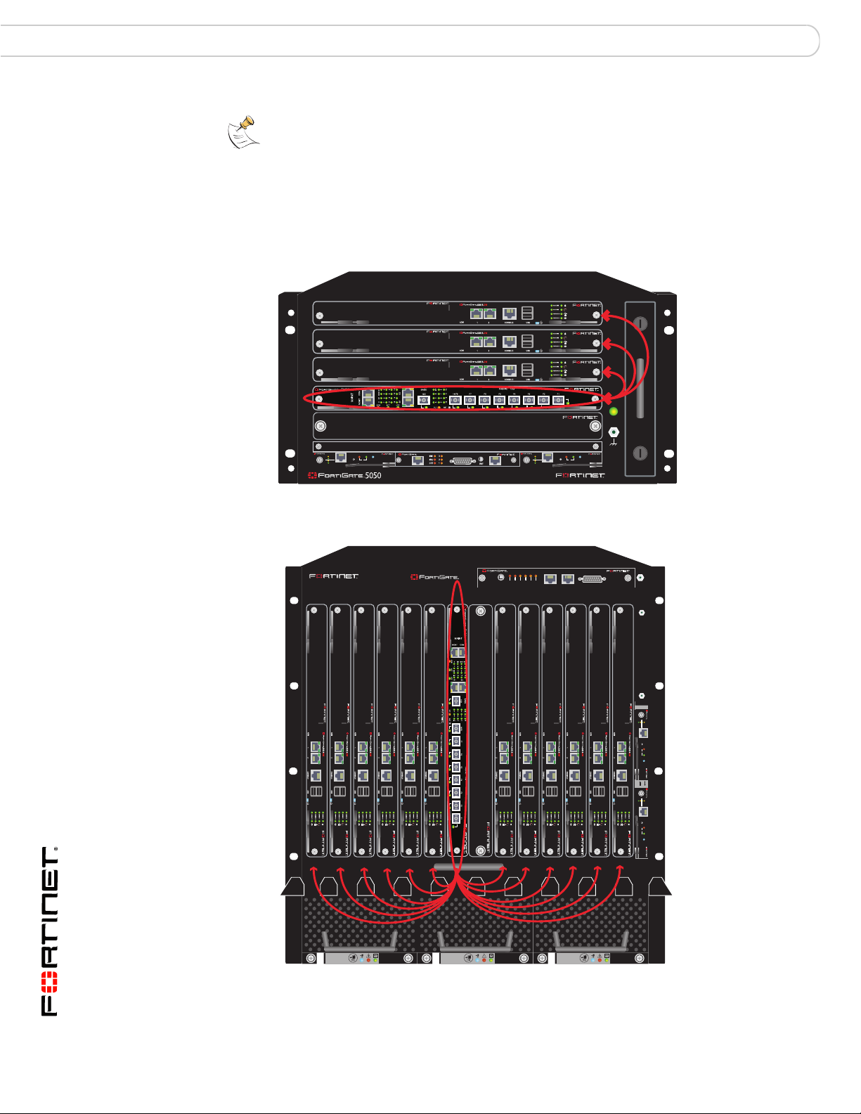
Base backplane HA configurations FortiGate-5140 and 5050 base backplane communication
1311975312468101214
5140
FILTER
12
0
12
Base channel 1
Note: Using a single FortiSwitch board for HA heartbeat communication introduces a single
point of failure. If this FortiSwitch board fails or is removed, HA heartbeat communication
will be interrupted. For enhanced reliability, you can add a second FortiSwitch board. You
can also improve reliability by connecting and configuring one or more other heartbeat
interfaces.
Figure 29: FortiGate-5050 HA cluster with one available base backplane heartbeat
interface (through a FortiSwitch-5003A board in slot 2)
Base channel 2
HA heartbeat
5
4
3
2
1
5000SM
10/100
SMC
ETH0
Service
link/Act
ETH1
10/100
RESET
ETH0
link/Act
2
Figure 30: FortiGate-5140 HA cluster with one available base backplane heartbeat
interface (through a FortiSwitch-5003A board in slot 1)
POWER
5050SAP
SERIAL
STATUS
Hot Swap
1
ALARM
5000SM
10/100
ETH0
Service
link/Act
ETH1
SERIAL
10/100
2
ETH0
link/Act
5140SAP
SERIAL 1 SERIAL 2 ALARM
USER2
USER1
USER3
MINOR
MAJOR
CRITICAL
RESET
SMC
STATUS
Hot Swap
RESET
1
5000SM
ETH1
ETH0
10/100
10/100
link/Act
link/Act
ETH0
Service
RESET
STATUS
Hot Swap
5000SM
ETH1
ETH0
10/100
10/100
link/Act
link/Act
ETH0
Service
RESET
STATUS
Hot Swap
FAN TRAY FAN TRAYFAN TRAY
FortiSwitch-5003A and 5003 Fabric and Base Backplane Communications Guide
74 01-30000-85717-20081205
Page 75
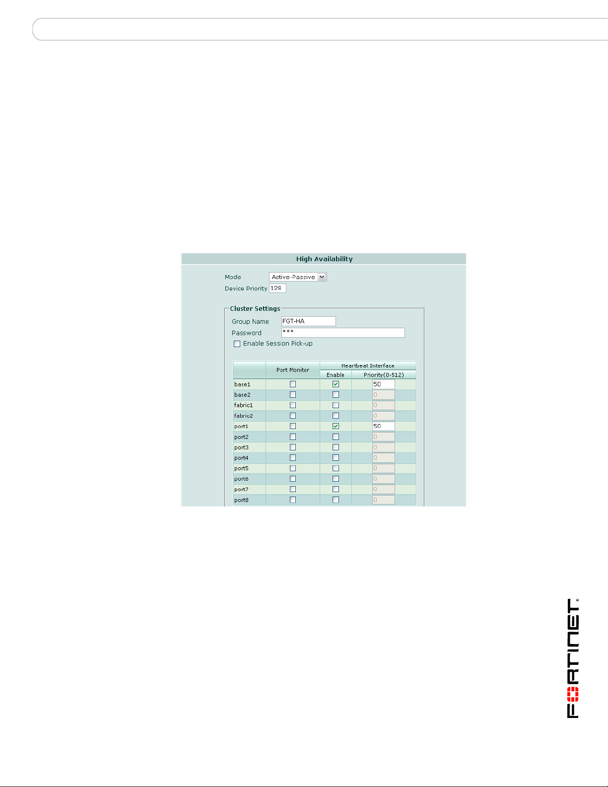
FortiGate-5140 and 5050 base backplane communication Base backplane HA configurations
To configure your HA cluster to use the base backplane interface connected
through a single FortiSwitch, the base backplane interface must be enabled as a
heartbeat interface and:
• if priorities are not equal, have the highest priority of all heartbeat interfaces
• if priorities are equal, be the first interface on the indexed heartbeat interface
list
You can satisfy these requirements in multiple ways by adjusting interface priority
or by disabling heartbeats for other interfaces. Required steps vary by the slot
position of the FortiSwitch board, the model of your FortiGate boards, and the
number and heartbeat interface list position of other interfaces enabled as
heartbeat interfaces.
Figure 31: FortiGate-5005FA2 HA through slot 1 (base1) with failover to a non-base
backplane interface (port1)
FortiSwitch-5003A and 5003 Fabric and Base Backplane Communications Guide
01-30000-85717-20081205 75
Page 76
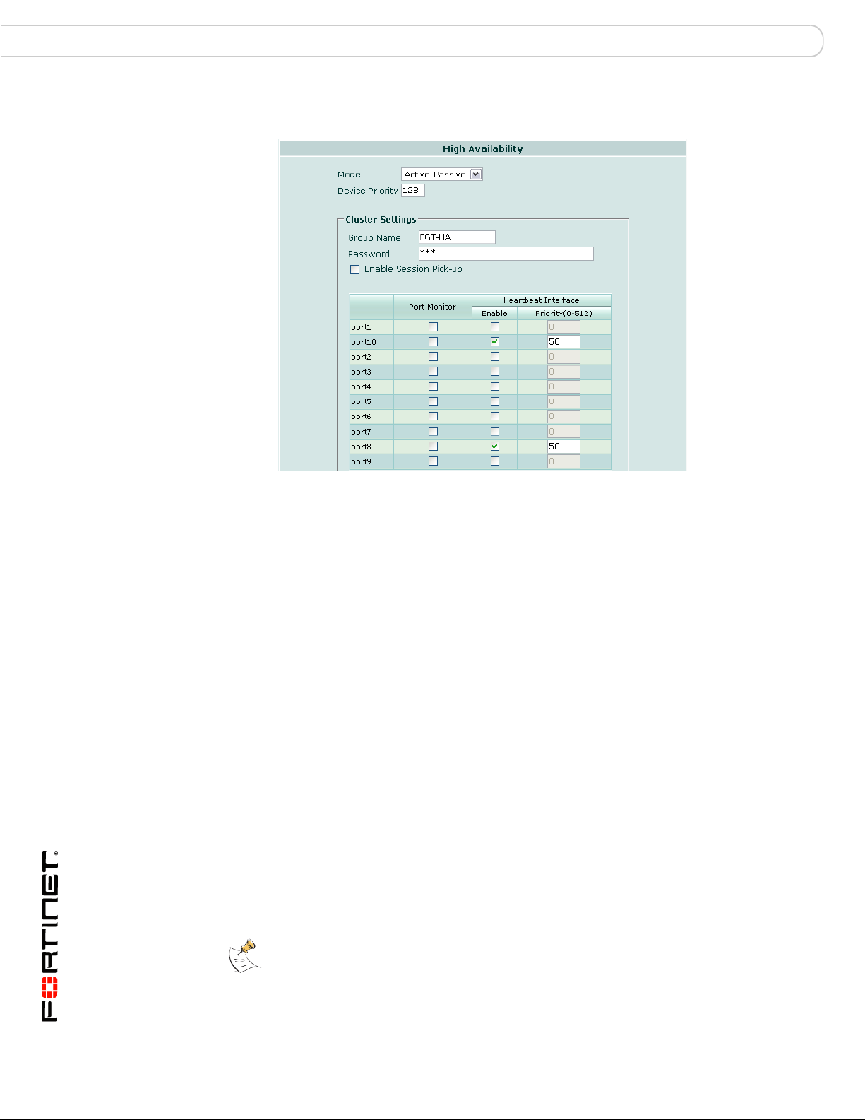
Base backplane HA configurations FortiGate-5140 and 5050 base backplane communication
Figure 32: FortiGate-5001SX/FortiGate-5001FA2 HA through slot 2 (port10) with
failover to a non-base backplane interface (port8)
To configure HA communications to use one FortiSwitch board
1 Insert the FortiSwitch board into chassis hub/switch slot 1 or hub/switch slot 2.
When installing only one FortiSwitch board per chassis, recommended slot
number varies by the model of the FortiGate boards. For details on the effects of
slot number, see “Slot position and HA heartbeat interface precedence” on
page 77.
If you want to form HA clusters between FortiGate boards in separate chassis,
install each FortiSwitch board into the matching slot number in each chassis, then
link the base backplanes of each chassis by connecting FortiSwitch boards front
panel base or ZRE interfaces with an Ethernet cable.
For example hardware installations, see Figure 30 on page 74 and Figure 29 on
page 74.
2 Insert FortiGate boards into the required chassis slots.
3 On each FortiGate board to be included in the HA cluster, go to System > Config
> HA.
4 Select the HA Mode, then enter the Group Name, and Password.
5 Set other HA options as required.
6 Enable the appropriate base backplane interfaces as heartbeat interfaces.
7 If the base backplane interface does not have heartbeat interface precedence,
increase the precedence of the base backplane interface so that it is selected as
the primary heartbeat interface.
Note: Heartbeat interface precedence can be determined by multiple factors, including
Priority and position in the Heartbeat Interface list. For details, see “Slot position and HA
heartbeat interface precedence” on page 77.
FortiSwitch-5003A and 5003 Fabric and Base Backplane Communications Guide
76 01-30000-85717-20081205
Page 77

FortiGate-5140 and 5050 base backplane communication Base backplane HA configurations
• If interface priorities are not all equal, set the base backplane interface priority
to a higher value than all other interfaces.
• If interface priorities are all equal, set the base backplane interface priority to a
higher value than all other interfaces, or disable interfaces listed above the
base backplane interface in the Heartbeat Interface list. For some FortiGate
models, FortiSwitch slot positions, or configurations of other HA interfaces, this
may mean that no change is required.
8 Select OK.
Choosing the slot position
Depending on the types of communications, HA or other, that you want to pass
through the base channels, you may choose to install FortiSwitch boards in
different slots: base hub/switch slot 1, base hub/switch slot 2, or both.
When using FortiSwitch boards to provide a network connection to the base
channels, hub/switch slot position does not matter. However, you can improve
robustness by installing FortiSwitch boards in both slots and providing a
redundant link.
For all types of communication, using both slots has the advantage of improving
reliability of communications through or to the base backplane because no
FortiSwitch is a single point of failure. Using both slots also provides the option of
separating multiple sensitive or high volume communications, such as HA
communications for multiple clusters.
Note: For HA configurations, you can further improve fault tolerance by adding one or more
non-base backplane interfaces as heartbeat interface failovers.
However, if you install only one FortiSwitch board, in addition to fault tolerance
considerations, the slot position has additional effects specific to HA.
• Inter-chassis HA configurations require that the switch use the same slot
number in each chassis so that each cluster member’s configuration uses the
same heartbeat interface.
• Slot position affects HA heartbeat interface selection and failover order.
Slot position and HA heartbeat interface precedence
When installing only one FortiSwitch board with an HA cluster of FortiGate-5001A
or FortiGate-5005FA2 boards, it is usually preferable to use hub/switch slot 1. This
allows you to connect one or more of the other FortiGate-5001A or
FortiGate-5005FA2 interfaces as backup HA heartbeat interfaces.
The preferred FortiSwitch board slot is different for FortiGate-50051SX and
FortiGate-5001FA2 board HA clusters. In this case, it is usually preferable to use
hub/switch slot 2.
The reason for selecting different slots is related to the mechanism for heartbeat
interface selection, which is indirectly tied to slot number.
During heartbeat interface selection, the heartbeat interface with the highest
priority is selected first. If multiple heartbeat interfaces have highest priority,
including when all have equal priority, the HA cluster chooses a heartbeat
interface using the Heartbeat Interface list.
FortiSwitch-5003A and 5003 Fabric and Base Backplane Communications Guide
01-30000-85717-20081205 77
Page 78

Base backplane HA configurations FortiGate-5140 and 5050 base backplane communication
This list is sorted into hash map order, rather than purely by alphabetical order or
purely by interface number value comparisons. As a result, the list is sorted
primarily alphabetical by interface name (for example, base1 is before port1), then
secondarily by index numbers:
•1
•10
• 2 through 8
•9
Note: For FortiOS versions 3.0 MR7 and earlier, the FortiGate web-based manager and
CLI list interfaces in sort order.
Because interface names, and therefore sort order, vary by FortiGate model, the
preferred slot number for single FortiSwitch boards varies by FortiGate model.
For example, a FortiGate-5001SX or FortiGate-5001FA2 board has interfaces
named port1 through port10; port9 and port10 are equally weighted heartbeat
interfaces, connected to the hub/switch slot 1 FortiSwitch and the hub/switch
slot 2 FortiSwitch, respectively. In the Heartbeat Interface list, port1 is first.
However, port10 is not last: due to hash map lookup,port10 is selected after port1
and before port2, not after port9. Failover passes heartbeat communications from
the FortiSwitch board in hub/switch slot 2 to hub/switch lot 1.
There are additional considerations if you create additional heartbeat backup
interfaces connecting FortiGate board interfaces port2 through port8. In this case,
if the FortiSwitch board in hub/switch slot 2 fails or is removed, the FortiGate
cluster could fail over to port2 through port8, and lastly fail over to the interface
connected to the FortiSwitch board in hub/switch slot 1.
Because of this behavior, if you install a single FortiSwitch board in hub/switch
slot 1 with those two models of FortiGate boards, and want to give heartbeat
selection precedence to the base backplane interface, you must set its heartbeat
interface priority to a greater value than the other interfaces. Otherwise, by
default, when priorities are equal, the heartbeat link through the base backplane
interface will be used only in failover, rather than primary, conditions. This is
typically the inverse of intended behavior.
For FortiGate-5001A and FortiGate-5005FA2 boards, the base backplane
interfaces are named base1 and base2. These interface names are always sorted
to the top of the interface list. So for a cluster of these boards, if you have a single
FortiSwitch board it doesn’t matter which slot you install it in because both base
interfaces are sorted to the top of the interface list.
FortiSwitch-5003A and 5003 Fabric and Base Backplane Communications Guide
78 01-30000-85717-20081205
Page 79

FortiGate-5140 and 5050 base backplane communication Base backplane data configurations
Base backplane data configurations
In addition to HA traffic, FortiSwitch boards can pass other traffic types through or
to the base backplane.
Note: FortiSwitch-5003 boards do not support VLAN-tagged packets, so if you are using
the FortiSwitch-5003 board base backplane traffic cannot include VLAN-tagged packets.
FortiSwitch-5003A boards do support VLAN-tagged packets over the base channels.
Like HA scenarios, network configurations can involve one or two FortiSwitch
boards per chassis, and one or more chassis.
However, unlike HA scenarios, boards connecting to transfer other traffic types
need not use identical interface numbers on each side of the connection, and
therefore they do not require FortiSwitch boards installed in the same slot
numbers. Because of this, by connecting one of the front panel base or ZRE
interfaces on each slot’s FortiSwitch board to another, you can send data traffic
between FortiGate boards that use different base backplane interfaces.
For example, if an HA cluster of FortiGate-5005FA2 boards using
hub/switchbase1 (hub/switch slot 1) for heartbeat traffic need to send some traffic
to a second HA cluster of boards in the same chassis that use base2 (hub/switch
slot 2) for their heartbeat traffic, you can connect the two clusters across the two
base backplane channels by linking one of the front panel base or ZRE interfaces
on the hub/switch slot 1 FortiSwitch board to one of the front panel base or ZRE
interfaces on the hub/switch slot 2 FortiSwitch board.
In addition to linking base backplane traffic between FortiGate boards, you can
use FortiSwitch boards to link traffic between FortiGate base backplane interfaces
and your network. Connecting a front panel base or ZRE interface to the network
links the base backplane, and any connected FortiGate boards, to the network.
Required steps vary by whether you want to use the base backplane interfaces to
connect FortiGate boards to each other, or to the network. These scenarios are
not mutually exclusive; you can simultaneously provide both.
Note: You can also combine network configurations with HA configurations to send both
traffic types through the base backplane channel(s). However, because heavy heartbeat or
network traffic load can interfere with the other traffic type’s performance, it is generally
preferable to separate those traffic types to different base backplane interfaces. This
requires two FortiSwitch boards per chassis.
Connecting FortiGate boards to each other
By installing one or two FortiSwitch boards per chassis, you can connect
FortiGate boards to each other through their base backplane interfaces.
Hardware configurations are identical to single and multiple chassis
configurations for HA traffic, except the additional possibility of connecting
FortiSwitch boards that have been installed in different slot numbers. Connecting
FortiSwitch boards located in different slot numbers allows communication
between the two base backplane channels.
Configure FortiGate boards to communicate through the base backplane
interfaces as you would other interfaces.
FortiSwitch-5003A and 5003 Fabric and Base Backplane Communications Guide
01-30000-85717-20081205 79
Page 80

Base backplane data configurations FortiGate-5140 and 5050 base backplane communication
Connecting FortiGate boards to the network
By installing one or two FortiSwitch boards per chassis, you can connect
FortiGate boards to the network or Internet through their base backplane
interfaces.
There are several ways you can connect FortiGate boards to the network,
depending on your available hardware and other goals such as hardware
redundancy.
• The most basic way to connect FortiGate boards to the network through the
base backplane is to connect one of the FortiSwitch front panel base or ZRE
interfaces to the network.
• By installing a second FortiSwitch board per chassis, you can provide a
redundant network connection.
• By connecting front panel base or ZRE interfaces of other chassis FortiSwitch
boards to the front panel base or ZRE interface of the FortiSwitch board
connected to the network, you can provide a shared network.
Configure FortiGate boards to communicate with the network through the base
backplane interfaces as you would other interfaces.
FortiSwitch-5003A and 5003 Fabric and Base Backplane Communications Guide
80 01-30000-85717-20081205
Page 81

FortiGate-5020 base backplane communication HA configurations
FortiGate-5020 base backplane communication
The FortiGate-5020 chassis has two base backplane Ethernet channels.
FortiGate modules installed in each slot can directly connect to the other slot
through either channel.
Because of the base backplane’s topology, connecting FortiGate modules to each
other through the base backplane does not require any additional hardware (that
is, FortiSwitch modules are not required). Modules connect to each other directly
through the base backplane as soon as they are installed.
The FortiGate-5020 base backplane can only be used to connect FortiGate
modules located in the same chassis. You cannot link the base backplanes of
multiple chassis to form inter-chassis HA clusters, and you cannot connect
FortiGate modules to the network through their base backplane interfaces.
Instead, inter-chassis HA or network traffic must pass through a FortiGate module
front panel interface. In these cases, additional hardware, such as an external
switch or Ethernet cables, may be required.
This section includes the following topics:
• HA configurations
• Inter-chassis HA configurations
• Network configurations
HA configurations
For a single FortiGate-5020 chassis, configuring HA between two FortiGate
modules through their base backplane interfaces is identical to configuring HA
between their front panel interfaces, except that their base backplane interfaces
are used. No additional hardware or cabling is required.
Because there are two available base backplane interfaces, you can configure
heartbeat interface failover to maintain communications through the base
backplane in the event of interface failure. For example, if you have a
FortiGate-5001SX cluster, you could configure the cluster to use port10 as the
primary heartbeat interface, and port9 as a backup if port10 fails.
Note: For enhanced reliability, connect and configure heartbeat failover to one or more
non-base backplane interfaces.
Heartbeat interface failover order is contingent on heartbeat interface Priority
and/or position in the Heartbeat Interface list. For details, see “Slot position and
HA heartbeat interface precedence” on page 77.
FortiSwitch-5003A and 5003 Fabric and Base Backplane Communications Guide
01-30000-85717-20081205 81
Page 82

HA configurations FortiGate-5020 base backplane communication
Heartbeat failover between channels
To configure your HA cluster with a heartbeat that fails over between the two base
backplane interfaces, both base backplane interfaces must be enabled and:
• if priorities are not equal, must have the highest priorities of all heartbeat
interfaces
• if priorities are equal, be the first interfaces on the indexed Heartbeat Interface
list
If you also want to specify which base backplane channel is used as the primary
or failover, its priority must be greater than the failover interface, or it must have a
higher position in the Heartbeat Interface list. Position in the Heartbeat Interface
list varies by the model of the FortiGate modules.
You can satisfy these requirements in multiple ways by adjusting interface priority
or by disabling heartbeats over other interfaces. Required steps vary by the model
of your FortiGate modules, and the number and Heartbeat Interface list position of
other interfaces enabled as heartbeat interfaces.
Default heartbeat interfaces vary by the model of the FortiGate modules, and are
not always base backplane interfaces. For example, FortiGate-5005FA2 modules
use the fabric backplane (fabric1 and fabric2), rather than the base backplane, by
default. If this is the case, to send heartbeat traffic through the base backplane,
you must enable and adjust the priority of the base backplane interfaces.
Conversely, FortiGate-5001SX and FortiGate-5001FA2 modules use base
backplane heartbeat interfaces by default, and do not require modification.
Figure 33: HA cluster with two available base backplane heartbeat interfaces
(directly connected through the base backplane)
PSU A
PSU B
USB
1 2 3 4 5 6 7 8
base
backplane
channel 1
CONSOLE
ACC
PWR
USB
1 2 3 4 5 6 7 8
CONSOLE
ACC
PWR
STA IPM
STA IPM
base
backplane
channel 2
FortiSwitch-5003A and 5003 Fabric and Base Backplane Communications Guide
82 01-30000-85717-20081205
Page 83

FortiGate-5020 base backplane communication HA configurations
Figure 34: FortiGate-5005FA2 heartbeat failover between base backplane channels
Figure 35: FortiGate-5001SX/FortiGate-5001FA2 heartbeat failover between base
backplane channels
To configure heartbeat interface failover between two base backplane
channels
1 Insert FortiGate modules into the chassis slots.
For details on hardware installation and related warnings and cautions, see the
FortiGate-5000 Series Introduction.
2 Power on each chassis.
FortiSwitch-5003A and 5003 Fabric and Base Backplane Communications Guide
01-30000-85717-20081205 83
Page 84

Inter-chassis HA configurations FortiGate-5020 base backplane communication
3 On each FortiGate module to be included in the HA cluster, go to System >
Config > HA.
4 Select the Mode, then enter the Group Name, and Password.
You may also want to set other options, such as the Device Priority or session
pick-up. For detailed instructions, see the FortiGate HA Guide.
5 If the base backplane interfaces do not have heartbeat interface precedence,
increase the precedence of the base backplane interfaces so that they are
selected as the primary and first failover heartbeat interface.
Note: Heartbeat interface precedence can be determined by multiple factors, including
Priority and position in the Heartbeat Interface list. For details, see “Slot position and HA
heartbeat interface precedence” on page 77.
• If interface priorities are not all equal, set the base backplane interfaces’
priority to a higher value than all other interfaces.
• If interface priorities are all equal, set the base backplane interfaces’ priority to
a higher value than all other interfaces, or disable interfaces listed above the
base backplane interfaces in the Heartbeat Interface list. For some FortiGate
models or configurations of other HA interfaces, this may mean that no change
is required. The table below describes where changes are required, and if so,
what kind.
6 If you want to select a different base backplane interface as the primary heartbeat
interface, increase its priority.
7 Select OK.
Inter-chassis HA configurations
Base backplane HA clustering between multiple FortiGate-5020 chassis is not
supported. To configure HA for FortiGate modules installed in separate
FortiGate-5020 chassis, you must instead connect the heartbeat through
FortiGate module front panel interfaces.
Note: For enhanced reliability, connect and configure heartbeat failover between two or
more non-base backplane interfaces.
Figure 36 on page 85 shows an HA cluster of four FortiGate-5001SX modules
installed in two separate FortiGate-5020 chassis. For each FortiGate module in
the example cluster:
• port1 connects to an internal network switch
• port2 connects to an external network switch, which is connected to the
Internet
• port7 and port8 connect to switches that handle only heartbeat traffic
• port3 to port6 are not used
FortiSwitch-5003A and 5003 Fabric and Base Backplane Communications Guide
84 01-30000-85717-20081205
Page 85

FortiGate-5020 base backplane communication Inter-chassis HA configurations
Figure 36: FortiGate-5020 inter-chassis network and heartbeat connections
Internal Network
internal network
CONSOLE
ACC
PWR
CONSOLE
ACC
PWR
USB
1 2 3 4 5 6 7 8
USB
1 2 3 4 5 6 7 8
Internet
switch
switch
PSU A
PSU B
STA IPM
STA IPM
ACC
PWR
ACC
PWR
switch
switch
Internet
USB
1 2 3 4 5 6 7 8
CONSOLE
USB
1 2 3 4 5 6 7 8
CONSOLE
inter-chassis heartbeat
STA IPM
STA IPM
inter-chassis heartbeat
PSU A
PSU B
Figure 37: FortiGate-5001SX/FortiGate-5001FA2 inter-chassis heartbeat interface
configuration
By default, FortiGate-5001SX modules use port9 and port10 (the base backplane
interfaces) as heartbeat interfaces. Because base backplane interfaces cannot be
used in inter-chassis configurations, if you want to form an inter-chassis HA
cluster, these default heartbeat interfaces should be disabled. In the above
example, the front panel interfaces port7 and port8 are enabled as heartbeat
interfaces, and port9 and port10 are disabled.
FortiSwitch-5003A and 5003 Fabric and Base Backplane Communications Guide
01-30000-85717-20081205 85
Page 86

Network configurations FortiGate-5020 base backplane communication
Network configurations
In addition to HA traffic, the FortiGate-5020chassis base backplane can pass
other traffic types, including VLAN tagged network traffic.
FortiGate modules do not necessarily have to be the same model. For example, if
you install a FortiGate-5005FA2 and a FortiGate-5001SX module in the same
FortiGate-5020 chassis, you can send network traffic between base1 of the
FortiGate-5005FA2 module and port9 of the FortiGate-5001SX module. You can
also send network traffic between base2 of the FortiGate-5005FA2 and port10 on
the FortiGate-5001SX module.
Traffic cannot traverse base backplane channels. For example, if you have
installed two FortiGate-5001SX modules in the same FortiGate-5020 chassis,
port9 on the module in slot1 can only send traffic to port9 in slot 2; port9 in slot 1
cannot send traffic to port10 in slot 2.
The FortiGate-5020 chassis base backplane only supports networking between
FortiGate modules located in the same FortiGate-5020 chassis. Unlike
FortiGate-5140 and FortiGate-5050 chassis, you cannot use the FortiGate-5020
base backplane to connect FortiGate modules to modules in another chassis, or
to the network, through their base backplane interfaces. Inter-chassis traffic and
traffic with the Internet or internal network must pass through a FortiGate module
front panel interface. In these cases, additional hardware, such as an external
switch or Ethernet cables, may be required.
Configure FortiGate modules to send network traffic through the base backplane
interfaces as you would other interfaces.
Figure 38: Network connection between modules in separate chassis, to the Internet,
and to the internal network
Internal Network
internal network
switch
CONSOLE
ACC
PWR
CONSOLE
ACC
PWR
USB
1 2 3 4 5 6 7 8
USB
1 2 3 4 5 6 7 8
Internet
PSU A
PSU B
STA IPM
STA IPM
switch
Internet
CONSOLE
ACC
PWR
CONSOLE
ACC
PWR
USB
1 2 3 4 5 6 7 8
USB
1 2 3 4 5 6 7 8
PSU A
PSU B
STA IPM
STA IPM
FortiSwitch-5003A and 5003 Fabric and Base Backplane Communications Guide
86 01-30000-85717-20081205
Page 87

FortiGate-5020 base backplane communication Network configurations
base
backplane
channel 1
base
backplane
channel 2
Figure 39: Network connection between two modules in the same chassis
PSU A
PSU B
USB
1 2 3 4 5 6 7 8
CONSOLE
ACC
PWR
USB
1 2 3 4 5 6 7 8
CONSOLE
ACC
PWR
STA IPM
STA IPM
FortiSwitch-5003A and 5003 Fabric and Base Backplane Communications Guide
01-30000-85717-20081205 87
Page 88

Network configurations FortiGate-5020 base backplane communication
FortiSwitch-5003A and 5003 Fabric and Base Backplane Communications Guide
88 01-30000-85717-20081205
Page 89

FortiSwitch-5003A CLI reference Connecting to the CLI
FortiSwitch-5003A CLI reference
This chapter describes the FortiSwitch-5003A CLI config, execute, and get commands and some
diagnose commands. This chapter also describes how to connect to the FortiSwitch-5003A CLI.
Working with the FortiSwitch-5003A CLI is the same as working with the FortiOS CLI. For information
about CLI command syntax, CLI objects and other CLI basics see the FortiGate CLI Reference.
This chapter describes:
• Connecting to the CLI
• config
• execute
• get
• diagnose
Connecting to the CLI
You can use a direct console connection, SSH, Telnet or the web-based manager to connect to the
FortiSwitch-5003A CLI. Using SSH or Telnet you connect to the CLI through the mgmt interface.
• Connecting to the FortiSwitch-5003A console
• Setting administrative access on the mgmt interface
• Connecting to the FortiSwitch-5003A CLI using SSH
Connecting to the FortiSwitch-5003A console
Connect to the FortiSwitch-5003A console using the FortiSwitch-5003A front panel COM port. You
need:
• a computer with an available communications port
• a null modem cable, with an RJ-45 connector as provided with your FortiSwitch-5003A board
• terminal emulation software such as HyperTerminal for Windows
Note: The following procedure describes how to connect to the FortiSwitch-5003A CLI using Windows
HyperTerminal software. You can use any terminal emulation program.
To connect to the CLI
1 Connect the FortiSwitch-5003A RJ-45 COM port to the available communications port on your
computer.
2 Make sure the FortiSwitch-5003A board is powered on.
3 Start HyperTerminal, enter a name for the connection, and select OK.
4 Configure HyperTerminal to connect directly to the communications port on the computer to which you
have connected the FortiSwitch-5003A COM port.
5 Select OK.
FortiSwitch-5003A and 5003 Fabric and Base Backplane Communications Guide
01-30000-85717-20081205 89
Page 90

Connecting to the CLI FortiSwitch-5003A CLI reference
6 Select the following port settings and select OK.
Bits per second 9600
Data bits 8
Parity None
Stop bits 1
Flow control None
7 Press Enter to connect to the FortiSwitch-5003A CLI.
A prompt similar to the following appears.
FS5A033E08000111 login:
The prompt includes the FortiSwitch-5003A host name. The default host name is the
FortiSwitch-5003A serial number.
8 Type a valid administrator name and press Enter.
The default administrator name is admin.
9 Type the password for this administrator and press Enter.
The default is no password.
A prompt similar to the following appears:
FS5A033E080001~#
Setting administrative access on the mgmt interface
To perform administrative functions through a the FortiSwitch-5003A mgmt network interface, you must
enable the required types of administrative access. Access to the CLI requires SSH or Telnet access.
To use the CLI to configure SSH or Telnet access
1 Connect and log into the FortiSwitch-5003A console.
2 Use the following command to configure the mgmt interface to accept SSH connections:
config system interface
edit mgmt
set allowaccess ping ssh telnet
end
3 To confirm that you have configured SSH or Telnet access correctly, enter the following command to
view the access settings for the interface:
get system interface mgmt
The CLI displays the settings, including allowaccess, for the named interface:
name : mgmt
status : up
ip : 172.20.120.178 255.255.255.0
allowaccess : ping ssh telnet
FortiSwitch-5003A and 5003 Fabric and Base Backplane Communications Guide
90 01-30000-85717-20081205
Page 91

FortiSwitch-5003A CLI reference Connecting to the CLI
Connecting to the FortiSwitch-5003A CLI using SSH
Secure Shell (SSH) provides strong secure authentication and secure communications to the
FortiSwitch-5003A CLI from your internal network or the internet. Once the FortiSwitch-5003A board is
configured to accept SSH connections, you can run an SSH client on your management computer and
use this client to connect to the FortiSwitch-5003A CLI.
To connect to the CLI using SSH
1 Install and start an SSH client.
2 Connect to the FortiSwitch-5003A mgmt interface.
3 Type a valid administrator name and press Enter.
4 Type the password for this administrator and press Enter.
A prompt similar to the following appears:
FS5A033E080001~#
You have connected to the FortiSwitch-5003A CLI, and you can enter CLI commands.
FortiSwitch-5003A and 5003 Fabric and Base Backplane Communications Guide
01-30000-85717-20081205 91
Page 92

config FortiSwitch-5003A CLI reference
config
The following config commands are available:
• admin user
• route static
• switch fabric-channel interface
• switch fabric-channel physical-port
• switch fabric-channel stp instance
• switch fabric-channel stp settings
• switch fabric-channel trunk
• system global
• system interface
admin user
Use this command to add and configure FortiSwitch-5003A administrator accounts. You cannot set
different access levels for FortiSwitch-5003A administrators.
Syntax
config admin user
edit <administrator_name>
set description <description_str>
set password <admin_password>
end
Variables Description Default
edit
<administrator_name>
description
<description_str>
password
<admin_password>
Enter a new administrator name to add or enter the name of
an administrator to edit. The <administrator_name> can
be up to 35 characters.
Describe the administrator account. The description can be up
to 128 characters.
Enter the password for this administrator. The password can
be up to 19 characters.
Example
This example shows how to add a new administrator called new_admin.
config admin user
edit new_admin
set description "A new administrator"
set password 123456
end
FortiSwitch-5003A and 5003 Fabric and Base Backplane Communications Guide
92 01-30000-85717-20081205
Page 93

FortiSwitch-5003A CLI reference config
route static
Use this command to add, edit, or delete static routes for the mgmt interface.
Syntax
config route static
edit <sequence_number>
set device <interface_name>
set dst <destination-address_ipv4mask>
set gateway <gateway-address_ipv4>
end
Variables Description Default
edit <sequence_number>
device <interface_name> The device name is always mgmt because you cannot
dst <destinationaddress_ipv4mask>
gateway <gatewayaddress_ipv4>
Enter a sequence number to identify the static route. No default.
configure routing for other FortiSwitch-5003A interfaces.
Enter the destination IP address and network mask for this
route.
You can enter 0.0.0.0 0.0.0.0 to create a default route.
Enter the IP address of the next-hop router to which traffic is
forwarded by this route.
mgmt
0.0.0.0
0.0.0.0
0.0.0.0
Example
This example shows how to add a default route for the mgmt interface that points to 192.168.22.44.
config route static
edit 2
set device mgmt
set dst 0.0.0.0 0.0.0.0
set gateway 192.168.22.44
end
Related topics
• config system interface
• execute traceroute
FortiSwitch-5003A and 5003 Fabric and Base Backplane Communications Guide
01-30000-85717-20081205 93
Page 94

config FortiSwitch-5003A CLI reference
switch fabric-channel interface
Use this command to configure the VLANs allowed on FortiSwitch-5003A fabric channel interfaces.
You can also change the native VLAN for each interface and disable or enable MSTP for each
interface.
Syntax
config switch fabric-channel interface
edit <interface_name>
set native-vlan <id_number>
set allowed-vlans <id_numbers>
set stp-state {disable | enable}
end
Variables Description Default
edit <interface_name> Enter the name of the FortiSwitch-5003A fabric channel
native-vlan <id_number> Change the IEEE 802.1Q native VLAN ID for this interface.
allowed-vlans
<id_numbers>
stp-state {disable |
enable}
interface or trunk to configure. The interfaces added to a trunk
do not appear in this list. You cannot edit an interface that has
been added to a trunk.
For the fabric channel <interface_name> can be:
• slot-2/1 used to connect the fabric channels of two
FortiSwitch-5003A boards installed in the same chassis.
• slot-3 FortiGate chassis slot 3.
• slot-4 FortiGate chassis slot 4.
• slot-5 FortiGate chassis slot 5.
• slot-6 FortiGate-5140 chassis slot 6.
• slot-7 FortiGate-5140 chassis slot 7.
• slot-8 FortiGate-5140 chassis slot 8.
• slot-9 FortiGate-5140 chassis slot 9.
• slot-10 FortiGate-5140 chassis slot 10.
• slot-11 FortiGate-5140 chassis slot 11.
• slot-12 FortiGate-5140 chassis slot 12.
• slot-13 FortiGate-5140 chassis slot 13.
• slot-14/f8 FortiGate-5140 chassis slot 14 or
FortiSwitch-5003A front panel slot 14/F8.
• f7 FortiSwitch-5003A front panel slot F7.
• f6 FortiSwitch-5003A front panel slot F6.
• f5 FortiSwitch-5003A front panel slot F5.
• f4 FortiSwitch-5003A front panel slot F4.
• f3 FortiSwitch-5003A front panel slot F3.
• f2 FortiSwitch-5003A front panel slot F2.
• f1 FortiSwitch-5003A front panel slot F1.
Packets tagged with the native VLAN ID are not modified when
sent or received by the interface. If an untagged packet is
received by the interface, the packet is tagged with the native
VLAN ID.
Specify the IEEE 802.1Q VLAN IDs that can be added to
VLAN-tagged packets that this interface can receive and
transmit. Packets tagged with other VLAN IDs are dropped by
the interface. Untagged packets are not affected.
You can enter any combination of single VLAN IDs and ranges
of VLAN IDs. Use a hyphen to specify ranges. Separate each
single ID or range with a comma. Do not include spaces. For
example: 1,3-4,6,7,9-100.
Enable or disable Multi-Spanning Tree Protocol (MSTP) for this
interface. If MSTP is disabled you cannot use this interface in
MSTP configurations.
1
enable
FortiSwitch-5003A and 5003 Fabric and Base Backplane Communications Guide
94 01-30000-85717-20081205
Page 95

FortiSwitch-5003A CLI reference config
Example
This example shows how to allow VLAN tags 201 to 210 on slots 6, 8, and 10 and the F1 front panel
interface.
config switch fabric-channel interface
edit "slot-6"
set allowed-vlans 1,201-210
next
edit "slot-8"
set allowed-vlans 1,201-210
next
edit "slot-10"
set allowed-vlans 1,201-210
next
edit "f1"
set allowed-vlans 1,201-210
end
Related topics
• config switch fabric-channel physical-port
• config switch fabric-channel stp instance
• config switch fabric-channel stp settings
• config switch fabric-channel trunk
FortiSwitch-5003A and 5003 Fabric and Base Backplane Communications Guide
01-30000-85717-20081205 95
Page 96

config FortiSwitch-5003A CLI reference
switch fabric-channel physical-port
Use this command to change the administrative status of FortiSwitch-5003A fabric channel interfaces
(bring each interface up or down) and configure each fabric channel interface to receive heartbeat
packets from FortiGate-5001A or 5005FA2 fabric channel interfaces.
Syntax
config switch fabric-channel physical-port
edit <interface_name>
set native-vlan <id_number>
set allowed-vlans <id_numbers>
set stp-state {disable | enable}
end
Variables Description Default
edit <interface_name> Enter the name of the FortiSwitch-5003A fabric channel
heartbeat {disable |
enable}
status {down | up} Bring the interface up or down. up
interface to configure. You cannot configure physical port
settings for a trunk. You can configure physical port settings for
interfaces that have been added to a trunk.
For the fabric channel <interface_name> can be:
• slot-2/1 used to connect the fabric channels of two
FortiSwitch-5003A boards installed in the same chassis.
• slot-3 FortiGate chassis slot 3.
• slot-4 FortiGate chassis slot 4.
• slot-5 FortiGate chassis slot 5.
• slot-6 FortiGate-5140 chassis slot 6.
• slot-7 FortiGate-5140 chassis slot 7.
• slot-8 FortiGate-5140 chassis slot 8.
• slot-9 FortiGate-5140 chassis slot 9.
• slot-10 FortiGate-5140 chassis slot 10.
• slot-11 FortiGate-5140 chassis slot 11.
• slot-12 FortiGate-5140 chassis slot 12.
• slot-13 FortiGate-5140 chassis slot 13.
• slot-14/f8 FortiGate-5140 chassis slot 14 or
FortiSwitch-5003A front panel slot 14/F8.
• f7 FortiSwitch-5003A front panel slot F7.
• f6 FortiSwitch-5003A front panel slot F6.
• f5 FortiSwitch-5003A front panel slot F5.
• f4 FortiSwitch-5003A front panel slot F4.
• f3 FortiSwitch-5003A front panel slot F3.
• f2 FortiSwitch-5003A front panel slot F2.
• f1 FortiSwitch-5003A front panel slot F1.
Enable or disable listening for heartbeat packets from
FortiGate-5001A or 5005FA2 fabric interfaces.
If you enable listening for heartbeat packets on interfaces
added to link aggregation trunks the FortiSwitch-5003A board
can detect if a FortiGate-5001A or 5005FA2 board is no longer
available. You must configure the FortiGate-5001A or 5005FA2
board to send heartbeat packets using the following
FortiGate-5001A or 5005FA2 CLI command:
config system global
set fortiswitch-heartbeat enable
end
disable
FortiSwitch-5003A and 5003 Fabric and Base Backplane Communications Guide
96 01-30000-85717-20081205
Page 97

FortiSwitch-5003A CLI reference config
Examples
This example shows how to enable the FortiSwitch-5003A board to listen for heartbeat packets on the
interfaces for chassis slots 6, 8, and 10:
config switch fabric-channel physical-port
edit "slot-6"
set heartbeat enable
next
edit "slot-8"
set heartbeat enable
next
edit "slot-10"
set heartbeat enable
end
This example shows how to bring down the slot-2/1 FortiSwitch-5003A interface. You may need to
bring this interface down to disable communication between fabric channel 1 and fabric channel 2.
config switch fabric-channel physical-port
edit slot-2/1
set status down
end
Related topics
• config switch fabric-channel interface
• config switch fabric-channel stp instance
• config switch fabric-channel stp settings
• config switch fabric-channel trunk
FortiSwitch-5003A and 5003 Fabric and Base Backplane Communications Guide
01-30000-85717-20081205 97
Page 98

config FortiSwitch-5003A CLI reference
switch fabric-channel stp instance
Use this command to add and configure 802.1s Multi-Spanning Tree Protocol (MSTP) spanning tree
instances. A spanning tree instance consists of the following:
• An instance ID
• A priority value
• A VLAN range
• A cost and priority value for each FortiSwitch-5003A interface (configured with the
config stp-port command).
Syntax
config switch fabric-channel stp instance
edit <instance_id>
set priority <priority_value>
set vlan-range <id_numbers>
config stp-port
edit <interface_name>
set cost <cost_int>
set priority <priority_value>
end
end
Variables Description Default
edit <instance_id> Enter a numeric spanning tree instance number in the range 0
priority <priority_value> The priority value of the FortiSwitch-5003A spanning tree
vlan-range <id_numbers> Specify the IEEE 802.1Q VLAN IDs that can be added to
to 15. All devices participating in an MSTP region must have
the same spanning tree instances.
The default configuration includes spanning tree instance 0 that
has a <priority_value> of 32768 and does not include a
vlan-range setting. The stp-port configuration of spanning
tree instance 0 sets the cost of all FortiSwitch-5003A interfaces
to 0 and the priority of all interfaces to 128.
32768
instance.
MSTP regions include multiple devices with the same spanning
tree instances. The different priority values of the same
instances on different devices determines how spanning tree
routes packets to the different devices. The device with the
spanning tree instance with the lowest priority value is more
likely to be the root device and to process all packets.
The <priority_value> range is 0 to 61440 in increments of
4096. Valid priority values are: 0, 4096, 8192, 12288, 16384,
20480, 24576, 28672, 32768, 36864, 40960, 45056, 49152,
53248, 57344, and 61440.
No default.
VLAN-tagged packets that this spanning tree instance can
receive and transmit. Only packets with these VLAN IDs are
affected by this spanning tree instance.
You can enter any combination of single VLAN IDs and ranges
of VLAN IDs. Use a hyphen to specify ranges. Separate each
single ID or range with a comma. Do not include spaces. For
example: 1,3-4,6,7,9-100.
FortiSwitch-5003A and 5003 Fabric and Base Backplane Communications Guide
98 01-30000-85717-20081205
Page 99

FortiSwitch-5003A CLI reference config
config stp-port
Use this command to change the spanning tree cost and priority for each FortiSwitch-5003A interface
in a spanning tree instance. When you add a new spanning tree instance the cost of each interface in
the spanning tree instance is set to 0 and the priority is set to 128.
Syntax
config stp-port
edit <interface_name>
set cost <cost_int>
set priority <priority_value>
end
Variables Description Default
edit <interface_name> Enter the name of the FortiSwitch-5003A fabric channel
cost <cost_int> Enter the cost for the FortiSwitch-5003Ainterface in the range
priority <priority_value> The priority value of the FortiSwitch-5003A interface in the
interface to configure. You cannot edit an interface that has
been added to a trunk. Edit the interface to change its spanning
tree cost and priority.
0
from 1 to 200000000. Spanning tree selects the interface with
the lowest cost.
Suggested values for different interface speeds:
• 10 Mbps: 20000000
• 100 Mbps: 200000
• 1 Gbps: 20000
• 10 Gbps: 2000
128
spanning tree instance. Spanning tree selects the interface with
the lowest priority.
The <priority_value> range is 0 to 240 in increments of
16. Valid priority values are 0, 16, 32, 64, 80, 96, 112, 128, 144,
160, 176, 192, 208, 224, and 240.
Example
This example shows how to add spanning tree instance 10 with priority 4096 and with a VLAN ID
range that includes 1, 200-210, and 23, 54, and 68. This instance also changes the cost and priority of
interface slot-13.
config switch fabric-channel stp instance
edit 10
set priority 4096
set vlan-range 1,200-210,23,54,68
config stp-port
edit slot-13
set cost 2000
set priority 16
end
end
Related topics
• config switch fabric-channel interface
• config switch fabric-channel physical-port
• config switch fabric-channel stp settings
• config switch fabric-channel trunk
FortiSwitch-5003A and 5003 Fabric and Base Backplane Communications Guide
01-30000-85717-20081205 99
Page 100

config FortiSwitch-5003A CLI reference
switch fabric-channel stp settings
Use this command to change MSTP spanning tree timers, specify an MSTP region name and use a
revision number to track changes to the MSTP configuration. All of these MSTP settings should be the
same on all of the devices in an MSTP region. These settings apply to all MSTP instances added to a
FortiSwitch-5003A board.
Syntax
config switch fabric-channel stp settings
set forward-time <delay_time_int>
set hello-time <hello_time_int>
set max-age <age_time_int>
set max-hops <hops_int>
set name <name_str>
set revision <number_str>
end
Variables Description Default
forward-time
<delay_time_int>
hello-time
<hello_time_int>
max-age
<age_time_int>
max-hops <hops_int> The maximum number of hops in a MSTP region. The range is 1 to 40.
name <name_str> Enter a region name for the spanning tree configuration. The name is
revision
<number_str>
The MSTP forward delay time in seconds. The forward delay time is
the number of seconds that spanning tree spends in the listening and
learning state. The range is 4 to 30 seconds.
Enter the time between sending bridge protocol data units (BPDUs).
The range is 1 to 10 seconds.
The max age timer controls the maximum length of time in seconds
that passes before a device saves its configuration BPDU information.
The range is 6 to 40 seconds.
The root bridge sends BPDUs with the hop count set to this maximum
value. When a device receives a BPDU, it decrements the remaining
hop count by one and includes this lower hop count in its BPDUs.
When a device receives a BPDU with a hop count of zero, the device
discards the BPDU.
optional. All devices in the same MSTP region should have the same
name. The region name is added to BPDUs.
Enter a revision number of up to 4 digits. All devices in an MSTP region
must have the same revision number. Change the revision number
manually whenever you change the MSTP configuration.
You can use the revision number to keep track of changes in the MSTP
configuration and to help confirm that the MSTP configurations of all of
the devices in a region are in sync.
15
2
20
20
0
Example
This example shows how to set the name of an MSTP region to "MSTP_test", set the revision to
1 and change the max-hops value to 4.
config switch fabric-channel stp instance
set name "MSTP_test"
set revision 1
set max-hops 4
end
Related topics
• config switch fabric-channel interface
• config switch fabric-channel physical-port
• config switch fabric-channel stp instance
• config switch fabric-channel trunk
FortiSwitch-5003A and 5003 Fabric and Base Backplane Communications Guide
100 01-30000-85717-20081205
 Loading...