

Page 1

FON-450i and FON-550i Telephones
User Guide
Page 2

FON-450i and FON-550i Telephones User Guide
July 12, 2012
27-400-166720-20120712
Copyright © 2012 Fortinet, Inc. All rights reserved. Fortinet®, FortiGate®, and FortiGuard®, are
registered trademarks of Fortinet, Inc., and other Fortinet names herein may also be trademarks
of Fortinet. All other product or company names may be trademarks of their respective owners.
Performance metrics contained herein were attained in internal lab tests under ideal conditions,
and performance may vary. Network variables, different network environments and other
conditions may affect performance results. Nothing herein represents any binding commitment
by Fortinet, and Fortinet disclaims all warranties, whether express or implied, except to the
extent Fortinet enters a binding written contract, signed by Fortinet’s General Counsel, with a
purchaser that expressly warrants that the identified product will perform according to the
performance metrics herein. For absolute clarity, any such warranty will be limited to
performance in the same ideal conditions as in Fortinet’s internal lab tests. Fortinet disclaims in
full any guarantees. Fortinet reserves the right to change, modify, transfer, or otherwise revise
this publication without notice, and the most current version of the publication shall be
applicable.
Technical Documentation docs.fortinet.com
Knowledge Base kb.fortinet.com
Customer Service & Support support.fortinet.com
Training Services training.fortinet.com
FortiGuard fortiguard.com
Document Feedback techdocs@fortinet.com
Page 3

Table of contents
Introduction....................................................................................................... 1
Phone Features........................................................................................................ 1
Requirements........................................................................................................... 1
Programmable/Flexible Key States ......................................................................... 3
LCD Layout .............................................................................................................. 3
Installing the FON-450i/FON-550i ................................................................... 5
Connecting the IP Phone......................................................................................... 5
Attaching the Stand ................................................................................................. 6
Wall Mounting .......................................................................................................... 7
Provisioning the FON-450i/FON-550i with FortiVoice ............................................. 7
Provisioning the FON-450i/FON-550i for use with an alternate system.................. 7
Personalizing your Phone................................................................................ 9
How to Navigate through Menus ............................................................................. 9
Entering Values with the Dial Pad and Softkeys...................................................... 9
Setting a Hunt Group as an Access Code Prefix..................................................... 9
Configuration Overview ......................................................................................... 10
Network Configuration........................................................................................... 10
Network Mode ................................................................................................. 10
IP Address........................................................................................................ 11
Subnet Mask.................................................................................................... 11
Default Gateway............................................................................................... 11
Primary DNS Address ...................................................................................... 12
Secondary DNS Address ................................................................................. 12
MAC Address................................................................................................... 12
VLAN Settings.................................................................................................. 12
VLAN Priority (LAN) .................................................................................... 13
VLAN ID (LAN)............................................................................................ 13
VLAN Priority (PC) ...................................................................................... 14
VLAN ID (PC).............................................................................................. 14
CDP.................................................................................................................. 15
SIP Configuration................................................................................................... 15
SIP Configuration, Line Parameters................................................................. 15
SIP Server Address .................................................................................... 15
Proxy Port .................................................................................................. 16
Display Name ............................................................................................. 17
User Name ................................................................................................. 17
Fortinet Technologies Inc. Page iii FON-450i and FON-550i Telephones User Guide
Page 4

Authentication User Name ......................................................................... 18
Authentication Password ........................................................................... 18
Registration Status..................................................................................... 19
Line Type.................................................................................................... 19
Extension for DSS Line .............................................................................. 20
SIP Configuration, General Parameters........................................................... 20
Outbound Proxy Address........................................................................... 20
Outbound Proxy Port ................................................................................. 21
Backup Proxy Address .............................................................................. 21
Backup Proxy Port ..................................................................................... 21
Local UDP Port .......................................................................................... 22
RTP Start Port ............................................................................................ 22
Proxy Registration...................................................................................... 23
Registration Expiry ..................................................................................... 23
Voicemail URL............................................................................................ 23
Domain....................................................................................................... 24
STUN Server .............................................................................................. 24
Phone Settings....................................................................................................... 24
LCD Contrast ................................................................................................... 25
Ring Settings.................................................................................................... 25
Default Ring Type....................................................................................... 25
Line Ring Setting........................................................................................ 25
Delayed Ring.............................................................................................. 26
Disable Ringer.................................................................................................. 26
Headset Auto Mode......................................................................................... 26
Flexible Key Setting ......................................................................................... 27
Time Configuration........................................................................................... 27
Speed Dial Number.......................................................................................... 27
Key Tone .......................................................................................................... 28
Language ......................................................................................................... 28
Backlight .......................................................................................................... 28
Bluetooth (FON-550i only, visible if optional Bluetooth module is installed) ... 28
Pairing a Bluetooth headset............................................................................. 29
Bluetooth Headset Status Indicators............................................................... 29
Connecting or Disconnecting a Paired Headset.............................................. 29
Deleting a Headset from the Paired List .......................................................... 30
Bluetooth Module Information ......................................................................... 30
Connect Mode ................................................................................................. 31
Call Preferences..................................................................................................... 31
Do Not Disturb ................................................................................................. 31
Fortinet Technologies Inc. Page iv FON-450i and FON-550i Telephones User Guide
Page 5

Call Waiting ...................................................................................................... 31
Call Waiting Tone............................................................................................. 32
Call Hold Ringback .......................................................................................... 32
Message Waiting Tone .................................................................................... 33
Auto Answer..................................................................................................... 33
Anonymous Call Block..................................................................................... 33
Access Code Prefix.......................................................................................... 34
Directory ................................................................................................................ 34
Phone Book ..................................................................................................... 34
Adding a Phone Book Record ................................................................... 34
Loading a Contact List using a Web Browser ................................................. 35
To add entries to the Phone Book using the telephone interface ................... 36
Editing a Contact ....................................................................................... 36
Deleting a Phone Book Record.................................................................. 37
Deleting All Records................................................................................... 37
Searching the Phone Book ........................................................................ 38
Dialing from the Phone Book ..................................................................... 38
Call Log............................................................................................................ 39
Dialing from a Log...................................................................................... 39
Deleting (single or all entries) ..................................................................... 39
Saving an Entry to the Phone Book ........................................................... 39
Set to Defaults ....................................................................................................... 40
Lock/Unlock Config ............................................................................................... 40
Information............................................................................................................. 41
Reboot ................................................................................................................... 41
Using Web Manager for Configuration......................................................... 42
Login & Site Map ................................................................................................... 42
VoIP Configuration ................................................................................................ 44
Line based parameters .................................................................................... 45
General Parameters ......................................................................................... 45
LAN Configuration ................................................................................................ 46
LAN Configuration............................................................................................ 46
Call Preferences .................................................................................................... 47
Call Preferences............................................................................................... 47
Dial Plan................................................................................................................. 48
Routing Table .................................................................................................. 49
Simple Dial Plan ......................................................................................... 50
Complex Dial Plan...................................................................................... 50
2nd Dial Tone ............................................................................................. 50
Digit Map Table ............................................................................................... 51
Fortinet Technologies Inc. Page v FON-450i and FON-550i Telephones User Guide
Page 6

Simple Dial Plan ......................................................................................... 52
Complex Dial Plan...................................................................................... 52
2nd Dial Tone ............................................................................................. 52
Phone Information ................................................................................................. 53
Phone Settings ...................................................................................................... 54
Phone Settings................................................................................................. 54
Functions ......................................................................................................... 55
Ring Settings.................................................................................................... 55
User Define Rings (RTTTL)............................................................................... 55
Phone Book .......................................................................................................... 56
Loading a contact list using a web browser .................................................... 57
Downloading the phone book to a file on a PC using a web browser............. 57
Multicast Paging ................................................................................................... 58
Paging Prefix.................................................................................................... 58
Priority Paging Group....................................................................................... 58
General Paging Group ..................................................................................... 58
Programmable Keys ............................................................................................. 59
Call Log ................................................................................................................. 60
Network Time Configuration ................................................................................. 61
Configurable Parameters ................................................................................. 61
Upgrade Configuration ......................................................................................... 62
QoS Configuration ................................................................................................ 64
Diffserv Configuration ...................................................................................... 64
IEEE 802.1Q..................................................................................................... 64
Jitter Buffer Configuration................................................................................ 64
Load Default .......................................................................................................... 65
Reboot .................................................................................................................. 65
Using the FON-450i/FON-550i Phone ........................................................... 66
Receiving a Call ..................................................................................................... 66
Placing a Call ......................................................................................................... 66
Putting a Call on Hold............................................................................................ 67
Attended Call Transfer ........................................................................................... 67
Blind Call Transfer.................................................................................................. 67
To transfer a call without announcing the transfer .......................................... 67
Manual method .......................................................................................... 67
Simple method........................................................................................... 67
3-Party Conference................................................................................................ 68
Method 1: Setting up a conference call........................................................... 68
Method 2: Conferencing a second person with first person already on hold..... 68
Ending a conference call............................................................................ 68
Fortinet Technologies Inc. Page vi FON-450i and FON-550i Telephones User Guide
Page 7

Call Waiting............................................................................................................ 68
Redial ..................................................................................................................... 68
Preprogrammed Speed Dial Keys ......................................................................... 69
Dialing using a Speed Dial Number ....................................................................... 69
DND (Do Not Disturb)............................................................................................. 69
Muting a Call.......................................................................................................... 69
Accessing Your Voicemail ..................................................................................... 70
Line/Extension Appearance Coverage .................................................................. 70
Hotline/Warm-Line................................................................................................. 70
Using your FON-450i/FON-550i Phone with FortiVoice .............................. 71
Access an outside line ........................................................................................... 71
ACCESSING Features ........................................................................................... 71
Voicemail................................................................................................................ 72
Updating the Firmware .......................................................................................... 72
Troubleshooting ............................................................................................. 73
Information............................................................................................................. 73
Troubleshooting Guide .......................................................................................... 74
Appendix A. Specifications — FON-450i/FON-550i..................................... 75
Hardware Specifications........................................................................................ 75
Appendix B. Character Table for Dial Pad Model........................................ 76
Regulatory and Safety Notices...................................................................... 77
Radio Frequency Emissions .................................................................................. 77
FCC Compliance Statement ............................................................................ 77
Canadian Compliance Statement .................................................................... 77
European Union Declarations of Conformity ................................................... 77
Product Safety Instructions ................................................................................... 78
E-911 and use of the FON-450i/FON-550i with Multi-Line Telephone Systems... 78
Privacy ................................................................................................................... 78
Limited Warranty ............................................................................................ 79
Warranty Repair Services ...................................................................................... 79
Fortinet Technologies Inc. Page vii FON-450i and FON-550i Telephones User Guide
Page 8

Introduction
Congratulations on your purchase of the FortiFone FON-450i/ or FON-550i phone! The
FortiFone-450i and FON-550i are sophisticated SIP-based IP phones that can be used with
phone systems and service providers. This user guide provides detailed information on
configuration via the telephone interface and web interface. It also provides information on how
to use the phone with a FortiVoice phone system.
Phone Features
• 3.75” x 1.00” backlit LCD display (FON-450i),
3.5” x 1.25” backlit LCD display (FON-550i)
• 10 flexible keys with LEDs (FON-450i),
22 flexible keys with LEDs (FON-550i)
• Up to 34* line/extension/queue appearance options with LEDs (FON-450i),
Up to 46* line/extension/queue appearance options with LEDs (FON-550i)
• Message waiting with indicator lamp and tone
• Full duplex speakerphone
• Intercom paging with other FortiVoice extensions
• Built-in two-port, 10/100 Ethernet switch. Lets you share a connection with your computer.
• Inline PoE support eliminates the need for power adapters.
• Optional Bluetooth® module compatible with supported headset models (FON-550i only)
* Using two FortiFone FF-50e expansion modules
Requirements
• SIP based phone system such as the FortiVoice™ series of phone systems or a VoIP service
• Ethernet or fast Ethernet network for connection (10/100 Mbps)
• Power Source
provider account.
For Ethernet networks that supply in-line power:
• The network devices must conform to IEEE 802.3af specifications for PoE (Power over
Ethernet). Most PoE switches should be able to power up the phones since they draw
less than 6 watts.
For Ethernet networks that do not supply power to the phone:
• Use only the FON-450i/FON-550i power supply designed for the region you intend to use
the product. This adapter is rated with an output of 48v DC at 0.3 A and a positive tip.
Fortinet Technologies Inc. Page 1 FON-450i and FON-550i Telephones User Guide
Page 9
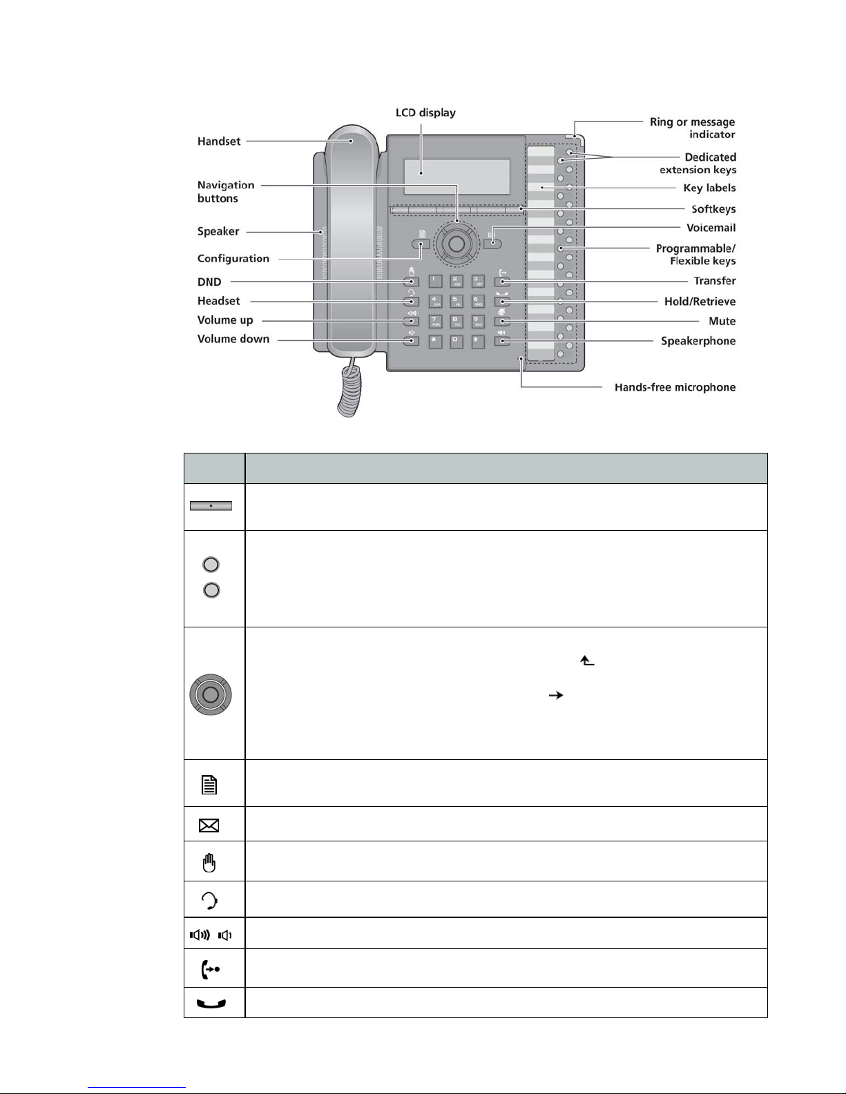
Figure 1: FON-550i front (FON-450i is the same with fewer programmable keys)
Item Function
Softkeys — Softkeys are interactive and change function based on the state of
the phone.
Programmable/Flexible keys — Multi-colored LED keys that can be assigned to
engage and monitor lines, extensions or queues. They can also be programmed as
function and speed dial keys. Keys 1 and 2 are reserved for primary and secondary
line appearance for the extension. Keys 3–12 (FON-450i) and 3–24 (FON-550i) are
programmable.
Navigation buttons
Left — use to view previous menu when return arrow appears in LCD menu.
Press to go back to previous menus while in the configuration menus.
Right — use to see additional menu items when appears in LCD menu.
Up — use to view Call Log when phone is idle.
Down — use to access Phone Book while phone is idle.
OK — center button, use to select current item or save value in LCD menu.
Configuration — Pressing this button accesses the menu for making changes to the
IP phone configuration.
Voicemail — Use to access voicemail status and access messages.
DND (Do Not Disturb) — Use to toggle on/off the DND feature of the phone system.
Headset — Toggles the headset on and off-hook.
Volume control — Use to adjust ring, headset, handset, and speaker volume.
Transfer — Use to transfer an active call.
Hold/Retrieve — Use to place or retrieve a call on hold.
Fortinet Technologies Inc. Page 2 FON-450i and FON-550i Telephones User Guide
Page 10
Item Function
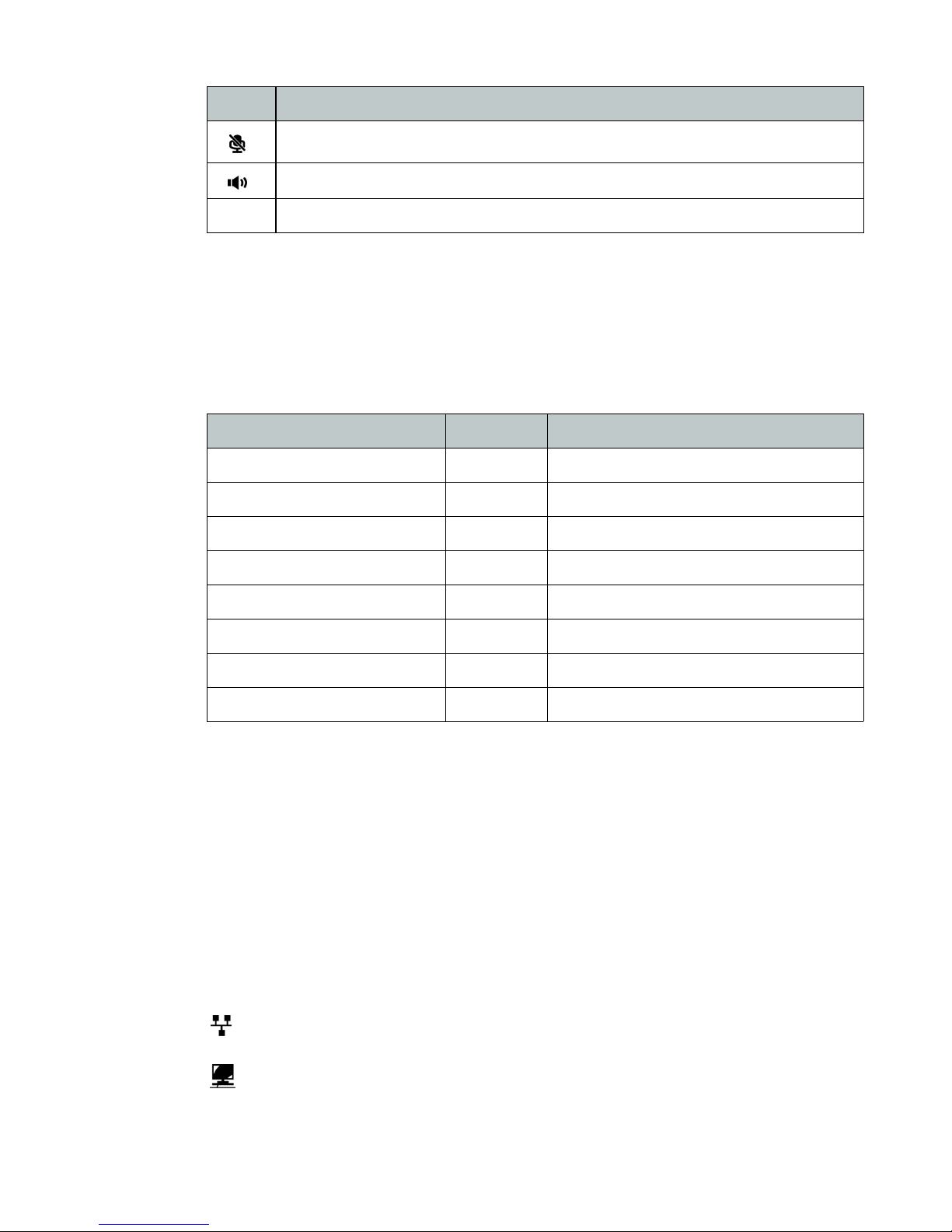
Mute — Use to mute and unmute the microphone during calls.
Speakerphone — Press to engage the speakerphone and to hang up after the call.
Dial pad — Use to dial a number, select a menu item, or input a value.
Programmable/Flexible Key States
The flexible keys access lines, extensions and features based on the IP phone configuration.
Flexible keys assigned for line, extension or queue appearances will monitor the state of those
resources and allow access to those resources at anytime unless the call is engaged by another
user or the system. Keys designated to monitor lines, extensions or queues indicate call status
as indicated below.
Status LED Color LED Pattern
Incoming call Green Flashing approx. once every 1/2 second
Line in use on this phone Green On solid
Call on hold at extension Green Flashing approx. once every second
LCD Layout
Line/Extension/Queue ringing Green Flashing approx. once every 1/2 second
Line/Extension/Queue in use Red On solid
Line/Extension/Queue on hold Red Flashing approx. once every second
Extension/Line not registered Red/Yellow Alternating Red and Yellow
Do Not Disturb (DND) enabled Yellow On solid
Flexible keys not assigned for line access may access features such as Speed dial, Intercom,
Park and others.
The FON-450i phone has a 240x42 dot graphic LCD arranged to show 3 lines of text and is
used to display information to the user. The bottom line shows choices associated with the
three context-sensitive softkeys located just below the LCD.
The FON-550i phone has a 240x56 dot graphic LCD that shows 4 lines of text. The top-bar
status line displays icons, date and time. The bottom line shows choices associated with the
three context-sensitive softkeys located just below the LCD.
Below is a list of icons and their meaning (FON-550i only).
LAN or Network connection icon, indicates the status of the LAN connection to the IP
phone. If the icon is blinking, check the LAN connection.
PC port icon, when displayed, indicates a device such as a PC is connected to the PC
port of the IP phone.
Fortinet Technologies Inc. Page 3 FON-450i and FON-550i Telephones User Guide
Page 11

Bluetooth icon, indicates the optional Bluetooth module is properly installed with no
headsets paired to the phone. When blinking rapidly, the FON-550i is searching or
attempting to pair with a headset.
Bluetooth paired icon, indicates one or more (maximum 5) headsets are paired with the
module but none are active. When blinking rapidly, the FON-550i is attempting to pair or
connect a headset.
Bluetooth connected icon, indicates a headset is connected to the FON-550i. When
blinking rapidly, the FON-550i is searching or attempting to pair or disconnect a headset.
When blinking slowly, the Bluetooth headset is in use.
Fortinet Technologies Inc. Page 4 FON-450i and FON-550i Telephones User Guide
Page 12
Installing the FON-450i/FON-550i
Connecting the IP Phone
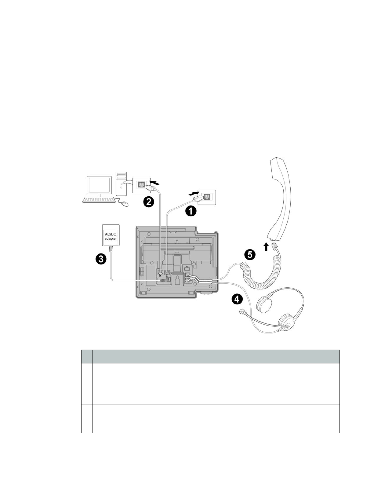
The figure below shows the cable connections for your IP phone. The LAN and desktop
PC connections employ standard Category 5 cables terminated with RJ-45 connectors. The
FON-450i/FON-550i supports PoE (Power over Ethernet) in accordance with the IEEE-802.1af
Class 2 standard. When connected to a PoE compliant LAN port, the IP Phone derives power
from the port. If the LAN port does not support PoE, use the AC/DC adaptor. The handset
connects to the base with the coiled handset cord.
Figure 2: IP phone connections
1 LAN Connect the IP phone LAN port to the LAN wall jack with the provided
2PC Optionally connect the IP phone PC port to your desktop PC with an Ethernet
3 Power If the LAN port supports PoE then the power adapter is not required. If PoE is
Fortinet Technologies Inc. Page 5 FON-450i and FON-550i Telephones User Guide
Wiring Chart
Ethernet cable.
cable (not supplied).
not supported on the LAN, connect the power adapter to the power jack on
phone.
Page 13
4 Headset Optionally connect a headset to the RJ22 headset jack on the phone.
5 Handset Connect the handset cord to the handset and the handset jack on the phone.
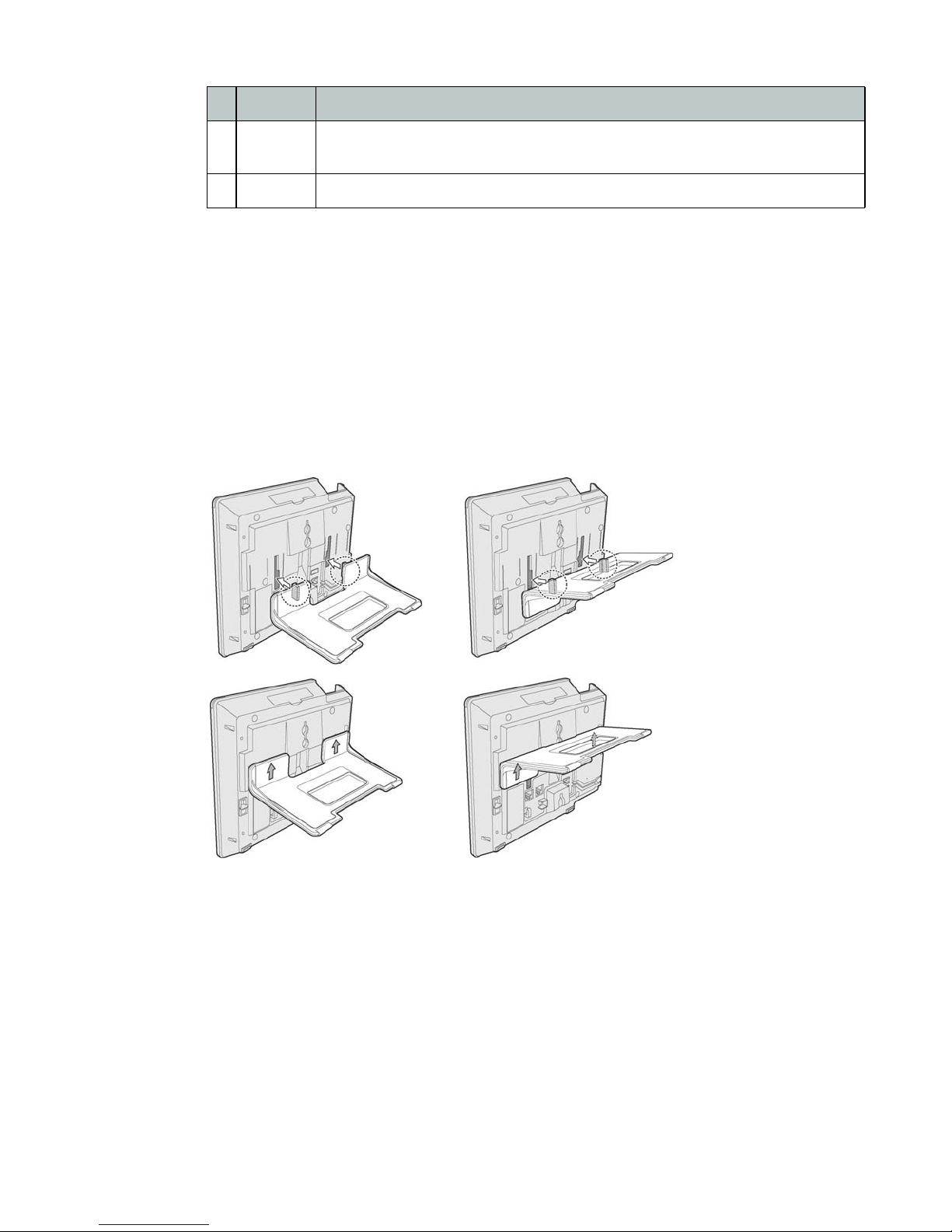
Attaching the Stand
The angle of the phone is set by the attachment of the provided stand in one of two positions
(30° or 55°).
To attach the stand,
1. Choose the desired angle for the phone.
2. Align the tabs on the stand with the notches in the base of the phone.
3. Push the stand upward in the slot as far as it can go until properly attached.
Figure 3: Installing the foot stand
Wiring Chart
We strongly recommend the use of an amplified headset.
55° angle 30° angle
Fortinet Technologies Inc. Page 6 FON-450i and FON-550i Telephones User Guide
Page 14
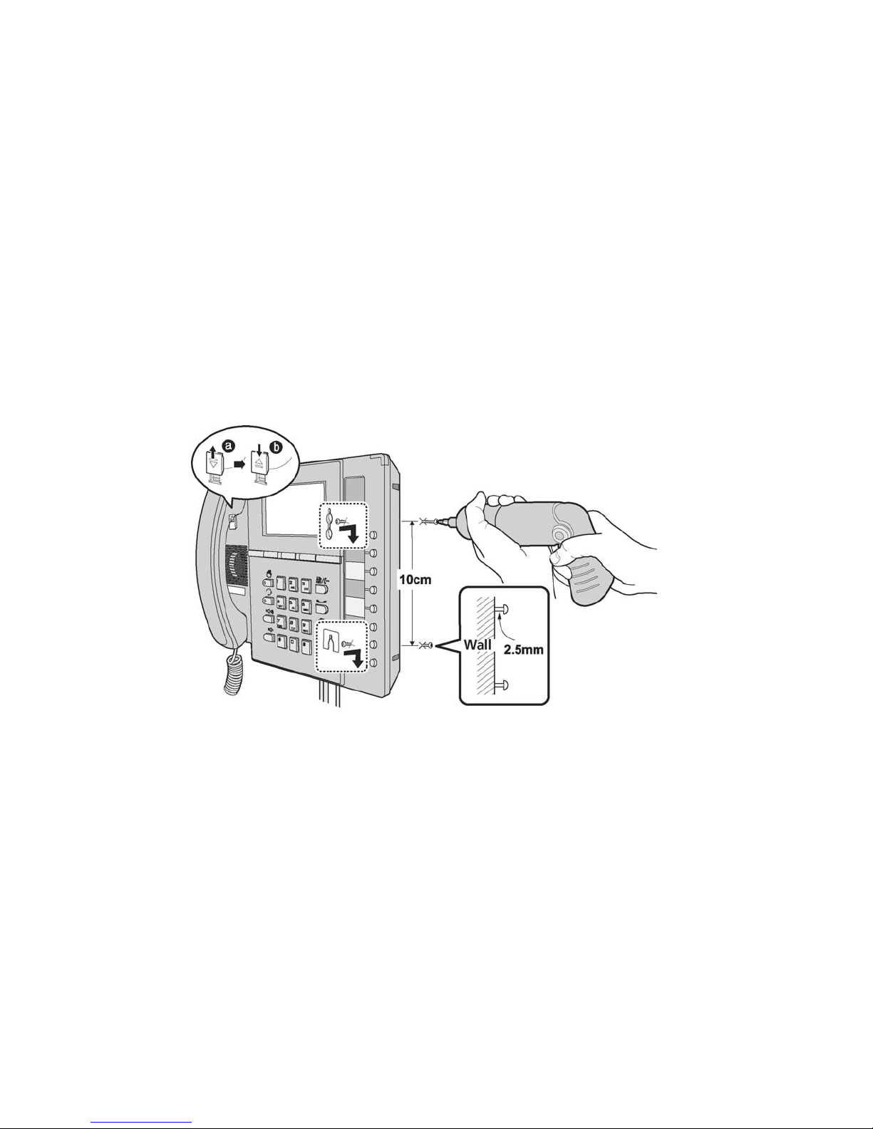
Wall Mounting
The FON-450i/FON-550i phone supports wall mounting via the base of the phone housing. Wall
mount the FON-450i/FON-550i using the instructions below in Figure 4.
• Mark and drill two 7 mm (5/16”) holes for plastic wall anchors (not included) with a vertical
• Insert two anchors into the holes, then insert and tighten the two screws (not included)
• Attach all wiring to the phone.
• Slide the phone over the screws and ensure the phone is secure. Note it may be necessary
• Remove the handset hook from the phone as shown in the figure below. Reverse the hook
• Complete all wiring.
Figure 4: FON-450i/FON-550i wall mount installation
separation of 10 cm (4”).
leaving about 2.5 mm (1/8”) exposed.
to remove the phone and tighten or loosen the screws for secure mounting. Also note, the
stand must not be attached to the phone when mounting on a wall.
and re-install in the phone so that the hook catches the groove in the handset receiver.
Provisioning the FON-450i/FON-550i with FortiVoice
If using the phone with FortiVoice, please refer to “Adding IP Phones” in Chapter 2 of the
FortiVoice User Guide for configuring the extensions in the FortiVoice software.
Provisioning the FON-450i/FON-550i for use with an alternate system
The FON-450i/FON-550i phone supports manual configuration when the automated process is
not available. As a minimum, the FON-450i/FON-550i requires the information below for proper
operation.
Line 1 SIP parameters including:
• Line 1 SIP call server IP address
• Line 1 Name (SIP user id)
• Line 1 Authentication user name
• Line 1 Authentication password
Fortinet Technologies Inc. Page 7 FON-450i and FON-550i Telephones User Guide
Page 15

In addition, using static IP addressing requires manual entry of the following IP network
configuration data.
• IP address of the phone
• Default gateway address
• Subnet mask
Two methods are available for manual configuration. The LCD Configuration Menu permits local
configuration using the dial pad and softkeys. The second method employs the
FON-450i/FON-550i Web Manager, which allows access to the IP phone configuration using a
Web browser. If configuring the phone for the first time, it is recommended that you use the Web
browser as it will save considerable time for the setup process.
Fortinet Technologies Inc. Page 8 FON-450i and FON-550i Telephones User Guide
Page 16

Personalizing your Phone
How to Navigate through Menus
To access the configuration menu:
• Press the button.
To select an item:
• Dial the digit associated with the menu item; or
• Use the Down softkey to move the cursor to the next item or alternatively use the navigation
up and down keys, then press the Select softkey or center navigation key to select an
option.
The bottom line of the display shows three (3) softkey functions at a time. Additional softkey
functions are available when the appears right of the softkey options on the LCD. Use the
Right navigation button to scroll through additional options.
To return to a previous branch in the menu, press the Back softkey, or left navigation button.
To exit the configuration menu, press the button.
Entering Values with the Dial Pad and Softkeys
Use the dial pad to input numbers, letters, special characters, and a period. The Mode softkey
displays to indicate a parameter can accept an alphanumeric entry. Selecting the Mode softkey
switches the dial pad mode. The dial pad mode displays in the right of the LCD above the
softkeys as for numeric, for upper case characters, for lower case characters and
for special characters.
To enter characters with the dial pad, use the digit with the desired character. Press the same
digit repeatedly until the desired character appears in the LCD. After entering a character, pause
to allow the cursor to move to next character position. Other special entries include:
• To enter a period or dot (for example, to input an IP address), press _ on the dial pad.
• To delete a letter in front of the cursor, press the softkey.
• To clear an entire string, press the Clear softkey.
• To enter a space, press ? on the dial pad.
Prior to saving an entry, you may discard changes by pressing the left navigation button to
move to the previous menu, or press the button to exit the Settings menu.
Setting a Hunt Group as an Access Code Prefix
If you need to dial 9 or 81–88 to access an outside line, then you will want to program your
phone to automatically insert a hunt group number before all calls placed from the Missed and
Received call logs as well as from the Phone Book. To set an Access Code:
• Press the button, select 4. Call Preferences, then 8. Access Code Prefix.
• Enter the hunt group you normally use to place outgoing calls (example: 9), then press the
OK softkey.
Fortinet Technologies Inc. Page 9 FON-450i and FON-550i Telephones User Guide
Page 17

Configuration Overview
The FON-450i/FON-550i supports the access and configuration of many parameters directly
from the Telephone User Interface. To access the Configuration menu, press the button while
the phone is not in use.
The configuration menu consists of several sub menus as listed below:
1. Network Configuration
2. SIP Configuration
3. Phone Settings
4. Call Preferences
5. Directory
6. Set to Defaults
7. Lock/Unlock Config
8. Information
9. Reboot Phone
Network Configuration
The Network Configuration menu allows the access and configuration of the network
parameters for the phone.
After any network configuration changes, you will receive a reboot notice. Changing network parameters
requires a reboot of the phone before the new values can be used. Networking parameters can only be
changed when the mode is set to Static.
Network Mode
The phone is capable of obtaining all of its IP configuration data from a DHCP server. When a
DHCP server is not available, static address parameters can be used. Selecting Static requires
the manual entry of other several network parameters including:
• IP address of the phone
• Default gateway IP address
• Subnet mask
• DNS address
To set the Network Mode:
• Press the button, then select 1. Network Configuration, then 1. Network Mode.
• Scroll the Network Mode options using the Down softkey and
press Select to select a Mode.
Fortinet Technologies Inc. Page 10 FON-450i and FON-550i Telephones User Guide
FON-550i screen
Page 18
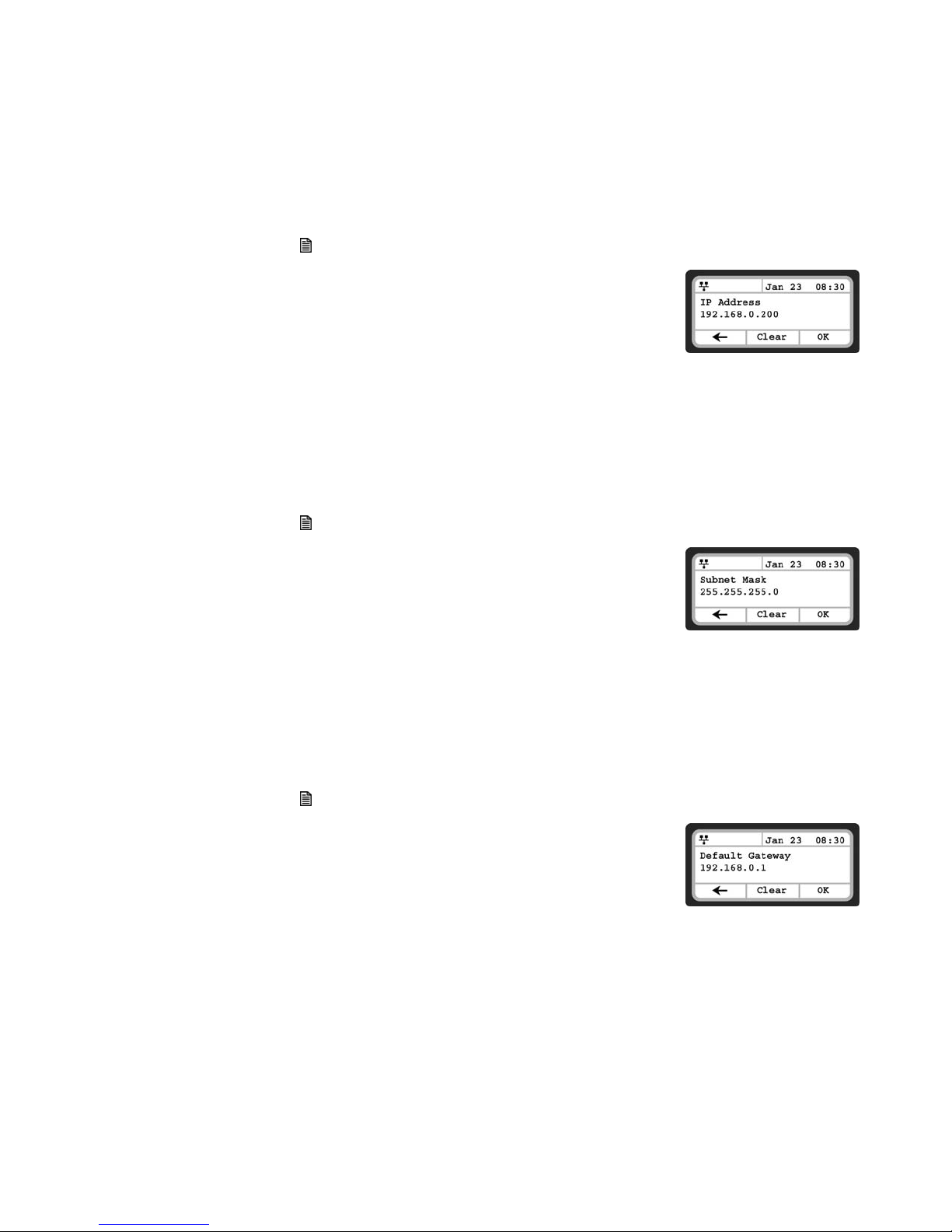
IP Address
By default the phone is configured to use DHCP to automatically assign an IP address and
other LAN parameters. Assigning a static address for the Network Mode requires manual entry
of an IP address and other parameters stated in the previous section. The phone requires a
valid available IP address for proper operation.
To set the IP Address:
• Press the button, then select 1. Network Configuration, then 2. IP Address.
• Input the IP Address using the dial pad and press the OK
softkey to save the changes.
Subnet Mask
Selecting static addressing for the Network Mode requires manual entry of a subnet mask. The
IP phone requires a valid subnet for proper operation.
To enter the Subnet Mask:
• Press the button, then select 1. Network Configuration, then 3. Subnet.
• Input the Subnet Mask using the dial pad and press the OK
softkey to save the changes.
FON-550i screen
Default Gateway
Selecting static addressing for the Network Mode requires manual entry of a default gateway
address. The IP Phone requires a valid default gateway address for proper operation.
To assign the Default Gateway address:
• Press the button, then select 1. Network Configuration, then 4. Default Gateway.
• Input the Default Gateway IP address using the dial pad and
press the OK softkey to save the changes.
FON-550i screen
FON-550i screen
Fortinet Technologies Inc. Page 11 FON-450i and FON-550i Telephones User Guide
Page 19
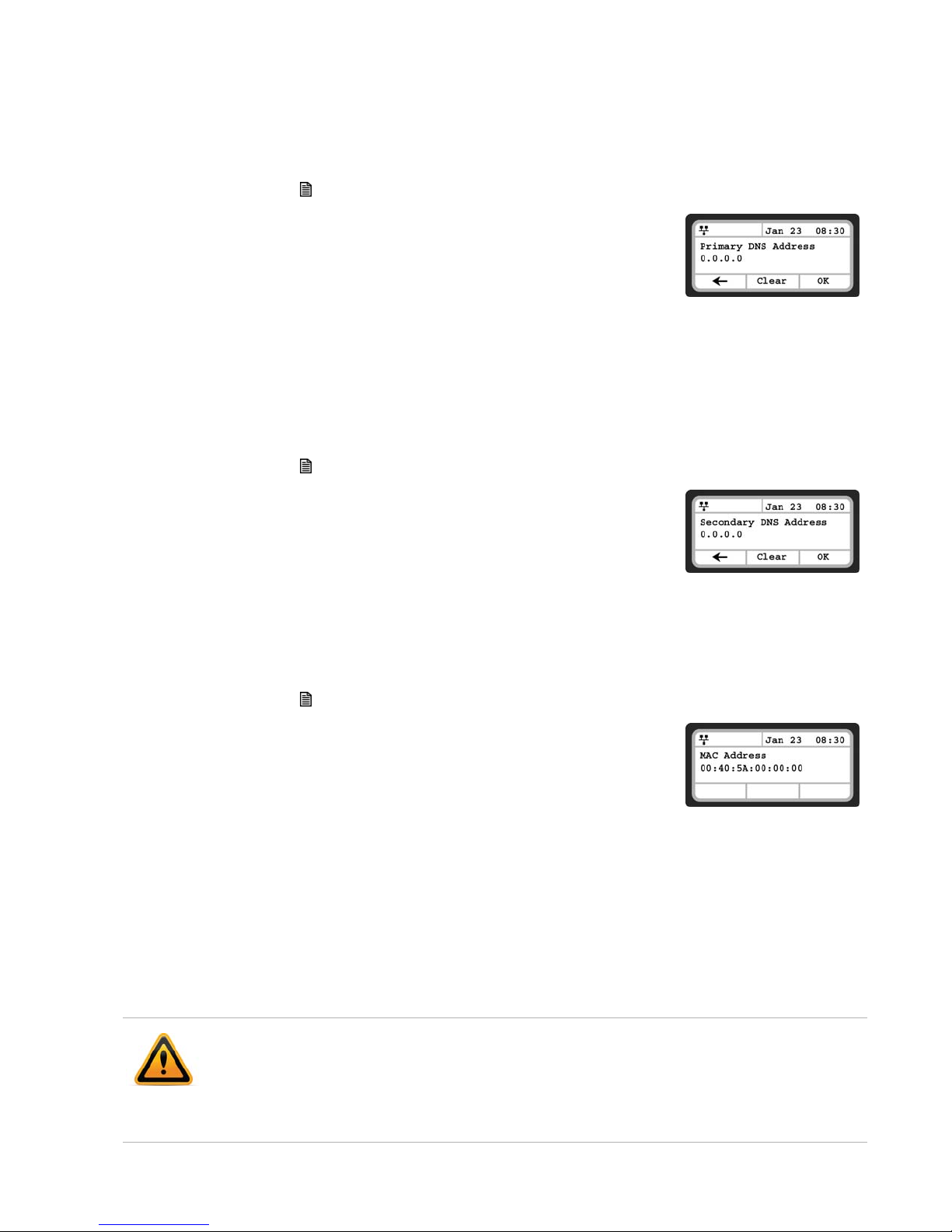
Primary DNS Address
The phone uses the primary DNS server to resolve any FQDN entries to an IP address.
To assign the Primary DNS Address:
• Press the button, then select 1. Network Configuration, then 5. Primary DNS Address.
• Input the Primary DNS Address using the dial pad and press the
OK softkey to save the changes.
Secondary DNS Address
Should the primary not respond, the phone will use the secondary DNS for FQDN resolution.
This is an optional but recommended setting.
To assign the Secondary DNS Address:
• Press the button, then select 1. Network Configuration, then 6. Secondary DNS Address.
• Input the Secondary DNS Address using the dial pad and press
the OK softkey to save changes.
FON-550i screen
MAC Address
To view the MAC address assigned and used by the phone:
• Press the button, then select 1. Network Configuration, then 7. MAC Address.
• The MAC address of the phone will be visible and should match
the one listed on the label on the bottom of the phone.
VLAN Settings
VLAN settings define the Ethernet frame priority and VLAN identification in accordance with IEEE
802.1p/Q standards. Separate VLAN tags are assigned for the IP phone PC port and the LAN
(voice) port. With a VLAN ID assigned, only frames with the assigned ID are accepted, and all SIP
and voice frames sent by the FON-450i/FON-550i include the VLAN ID assigned to the LAN port.
FortiVoice phone systems do not support VLAN tagging so this should not be used with FortiVoice
phone system deployments.
For proper operation, other network elements (LAN switches and default gateway) must
support and be configured with proper VLAN parameters.
FON-550i screen
FON-550i screen
VLAN settings are overwritten if CDP is enabled.
Changing the VLAN parameters requires a reboot of the IP phone. When you exit the menu, you
will receive a reboot notice. The phone must be rebooted to use the new values.
Fortinet Technologies Inc. Page 12 FON-450i and FON-550i Telephones User Guide
Page 20
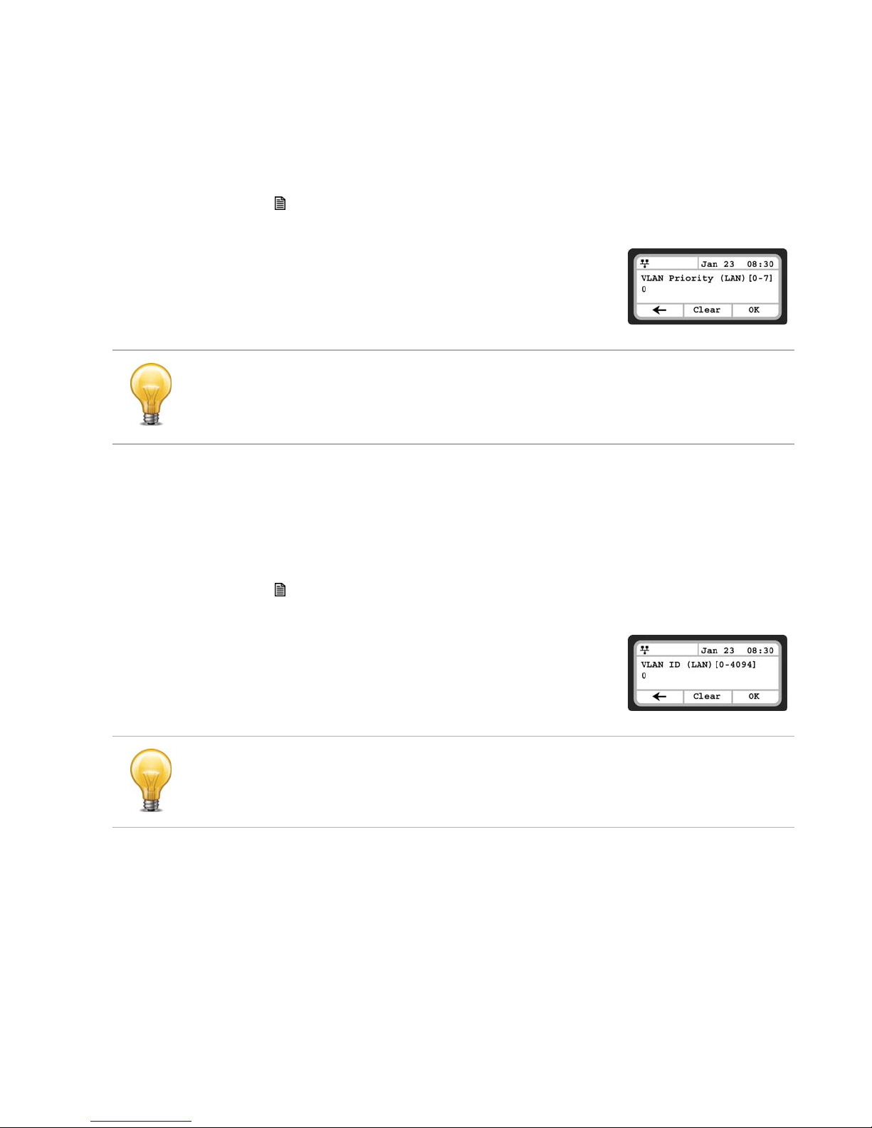
VLAN Priority (LAN)
The VLAN Priority (LAN) establishes the priority for Ethernet frames from the LAN port including
signaling and voice packets. Setting the VLAN ID to zero (0) disables VLAN framing and the IP
phone uses only standard Ethernet frames.
To assign VLAN Priority for the LAN (voice) port:
• Press the button, then select 1. Network Configuration, then 8. VLAN Settings.
• Select 1. VLAN Priority (LAN).
• Input the VLAN Priority for the LAN port using the dial pad and
press the OK softkey to save your entry.
FON-550i screen
Changing the VLAN Priority requires a reboot of the IP phone. When you leave the menu, you
will receive a reboot notice.
The recommended value for VLAN Priority (LAN) port is 5.
To disable VLANs, assign the VLAN ID as zero (0).
VLAN ID (LAN)
The VLAN ID (LAN) assigns the identification for Ethernet frames for the phone LAN port
including signaling and voice payloads. Setting the VLAN ID to zero (0) disables the VLAN
framing and the IP phone and uses only standard Ethernet frames.
To assign the VLAN ID for the LAN (voice) port:
• Press the button, then select 1. Network Configuration, then 8. VLAN Settings.
• Select 2. VLAN ID (LAN).
• Input the VLAN ID for the LAN port using the dial pad and press
the OK softkey to save your entry.
FON-550i screen
Changing the VLAN ID requires a reboot of the phone. When you exit the menu, you will receive
a reboot notice.
To disable VLANs, assign the VLAN ID as zero (0).
Fortinet Technologies Inc. Page 13 FON-450i and FON-550i Telephones User Guide
Page 21

VLAN Priority (PC)
The VLAN Priority (PC) establishes the priority for Ethernet frames for the phone PC port.
Setting the VLAN ID to zero (0) disables VLAN framing and the phone will use only standard
Ethernet frames.
To assign the VLAN Priority for the PC port:
• Press the button, then select 1. Network Configuration, then 8. VLAN.
• Select 3. VLAN Priority (PC).
• Input the VLAN Priority for the PC port using the dial pad and
press the OK softkey to save your entry.
FON-550i screen
Changing the VLAN Priority requires a reboot of the phone. When you exit the menu, you will
receive a reboot notice.
To disable VLANs, assign the VLAN ID as zero (0).
The recommended value for the VLAN Priority for the PC port is 3.
VLAN ID (PC)
The VLAN ID (PC) assigns the identification for Ethernet frames for the phone PC port. Setting
the VLAN ID to zero (0) disables VLAN framing and the phone will only use standard Ethernet
frames.
To assign the VLAN ID (PC) port:
• Press the button, then select 1. Network Configuration, 8. VLAN Settings.
• Select 4. VLAN ID (PC).
• Input the VLAN ID (PC) port using the dial pad and press the OK
softkey to save your entry.
FON-550i screen
Changing the VLAN ID (PC) requires a reboot of the phone. When you exit the menu, you will
receive a reboot notice.
To disable VLANs, assign the VLAN ID as zero (0).
Fortinet Technologies Inc. Page 14 FON-450i and FON-550i Telephones User Guide
Page 22

CDP
The FON-450i/FON-550i can be assigned to employ the Cisco® Discovery Protocol to
determine if VLANs are to be used and the associated VLAN ID. The CDP selection displays
only if function_cdp is enabled in the configuration file. As a default, the CDP parameter is
disabled since FortiVoice does not use VLAN tagging.
To set the CDP status:
• Press the button, then select 1. Network Configuration, then 9. CDP.
• Select the desired softkey (Yes or No) to enable or disable CDP.
Changing the CDP status requires a reboot of the phone. When you leave the menu, you will
receive a reboot notice.
When CDP is enabled, VLAN settings are overwritten.
SIP Configuration
FON-550i screen
The SIP Configuration section contains parameters related to SIP accounts, line appearance,
and other parameters that allow the phone to register and, if required, subscribe for the line
appearance with the appropriate SIP server or PBX.
Lines are assigned to the phone’s flexible buttons in consecutive order from the first button. For
each line, the following parameters are available:
• Call Server IP address
• Authorization ID and password
• Line type
• Special line attributes
As a default, the maximum number of lines is two. When the IP phone requires more than
two (2) lines, use the Web Manager or configuration file to change the number of lines and line
parameters.
At a minimum, assign the first line button as an appearance of the user's line. For features
where the IP phone uses one-button line access such as Speed Dial, the IP phone uses the first
line button for the call.
SIP Configuration, Line Parameters
Assign parameters in this section for each SIP line.
SIP Server Address
The SIP Server Address is the IP address or FQDN of the SIP server or PBX. Different SIP
servers can be defined for each line.
Fortinet Technologies Inc. Page 15 FON-450i and FON-550i Telephones User Guide
Page 23
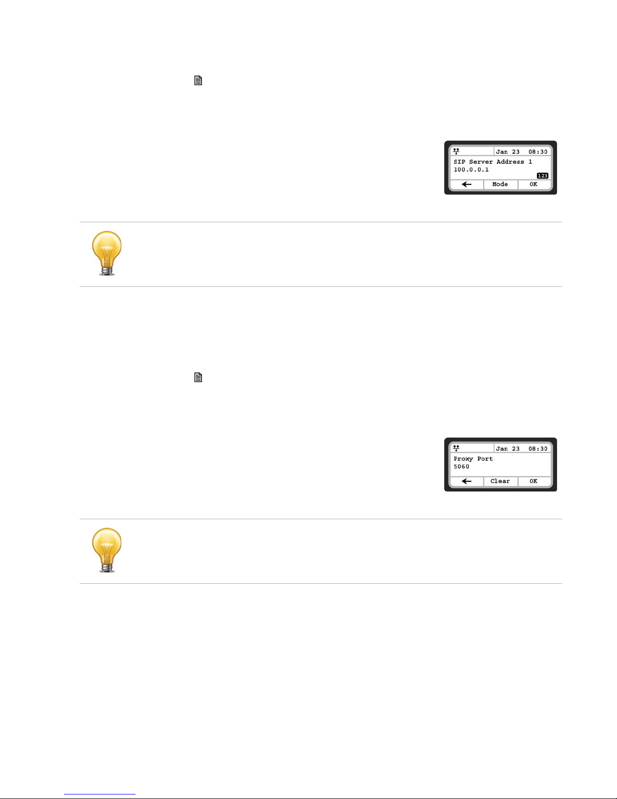
To assign the Call Server address:
• Press the button, then select 2. SIP Configuration, then 1. Line Configuration.
• Enter the line button number or move the cursor using the Down softkey and press the
Select softkey to select a line.
• Select 1. SIP Server Address.
• Input the SIP Server Address or FQDN using the dial pad and
press the OK softkey to save your entry.
FON-550i screen
Changing the SIP Server Address requires a reboot of the phone. When you exit the menu, you
will receive a reboot notice.
To enter alphanumeric characters select the Mode softkey.
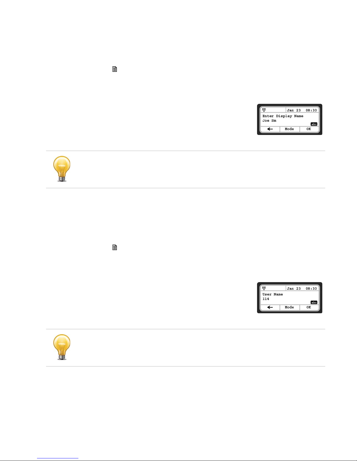
Proxy Port
The Proxy Port defines the UDP port number employed for SIP signaling transport. In common
practice, the port number 5060 is used.
To change the Proxy Port number:
• Press the button, then 2. SIP Configuration, then 1. Line Configuration.
• Enter the line button number or move the cursor using the Down softkey and press the
Select softkey to select a line.
• Select 2. Proxy Port.
• Input the Proxy Port number using the dial pad and press the
OK softkey to save your entry.
FON-550i screen
Changing the Proxy Port requires a reboot of the phone. When you exit the menu, you will
receive a reboot notice.
Fortinet Technologies Inc. Page 16 FON-450i and FON-550i Telephones User Guide
Page 24
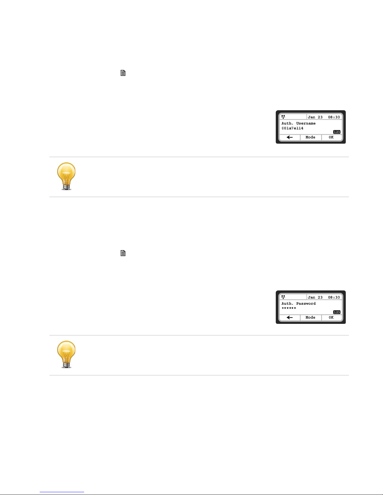
Display Name
When assigned, the Display Name is used in SIP calls as the Caller ID name.
To enter the Display Name:
• Press the button, then 2. SIP Configuration, then 1. Line Configuration.
• Enter the line button number or move the cursor using the Down softkey and press the
Select softkey to select a line.
• Select 3. Display Name.
• Input the Display Name using the dial pad and press the OK
softkey to save your entry.
FON-550i screen
To enter alphanumeric characters, select the Mode softkey.
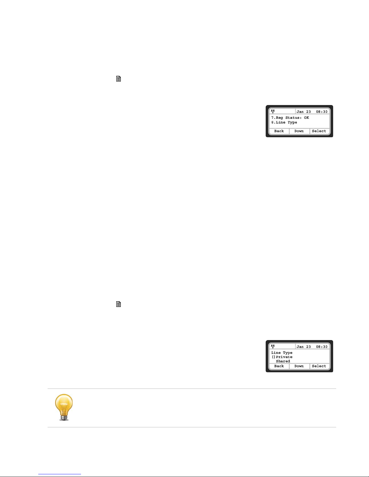
User Name
A User Name (extension or phone number) is required for proper operation and must match the
user ID or account assigned in the SIP server. This is usually the number dialed to reach this line
on the phone.
To enter the User Name:
• Press the button, then 2. SIP Configuration, then 1. Line Configuration.
• Enter the line button number or move the cursor using the Down softkey and press the
Select softkey to select a line.
• Select 4. User Name.
• Input the Name using the dial pad and press the OK softkey to
save your entry.
To enter alphanumeric characters, select the Mode softkey.
Fortinet Technologies Inc. Page 17 FON-450i and FON-550i Telephones User Guide
FON-550i screen
Page 25
Authentication User Name
Authentication of the line with the SIP call server requires an Authentication User Name.
• To assign the Authentication User Name:
• Press the button, then 2. SIP Configuration, then 1. Line Configuration.
• Enter the line button number or move the cursor using the Down softkey and press the
Select softkey to select a line.
• Select 5. Auth. Username.
• Input the Authentication User Name, as is spec if ed in the SIP
server, using the dial pad and press the OK softkey to save your
entry.
FON-550i screen
To enter alphanumeric characters, select the Mode softkey.
Authentication Password
Authentication of the line with the SIP call server requires an Authentication Password in
conjunction with the User Name.
To assign the Authentication Password:
• Press the button, then 2. SIP Configuration, then 1. Line Configuration.
• Enter the line button number or move the cursor using the Down softkey and press the
Select softkey to select a line.
• Select 6. Auth. Password.
• Input the Authentication Password using the dial pad and press
the OK softkey to save your entry.
FON-550i screen
To enter alphanumeric characters, select the Mode softkey.
Fortinet Technologies Inc. Page 18 FON-450i and FON-550i Telephones User Guide
Page 26
Registration Status
The status of the line registration with the SIP call server can be viewed from this menu. The
status is displayed as OK, NOK (Not registered) or undefined (not assigned).
To view the Registration status for a line:
• Press the button, then 2. SIP Configuration, then 1. Line Configuration.
• Enter the line button number or move the cursor using the Down softkey and press the
Select softkey to select a line.
• Select 7. Reg. Status to view the status.
• The status is actually shown next to the menu title.
FON-550i screen
Line Type
Each line represents a SIP account in the SIP server. A line must have a Line Type assignment.
The three line types available are private, shared or BLA (Bridged Line Appearance) and DSS
(Direct Station Selection). A private line generally appears on line buttons of one phone but may
appear at multiple phones as a Multiple Line Appearance (MLA). While incoming calls on a
private line ring at all phones with an appearance, an active or held private line call is accessible
only to the associated phone. In addition, the status of an active or held private line call displays
only at the associated phone. Only the active user may transfer or conference calls on a private
line.
A BLA appears at line buttons of more than one phone. All phones with an appearance can
access incoming and held calls on the BLA and receive status information for the call. Note for
proper operation, assign the line as a BLA in the call server as well as the IP Phone.
A DSS line incorporates three functions associated with the needs of an answering position:
• DSS — while the line is idle, the button calls the associated extension.
• BLF — the Busy Lamp Field LEDs of the line button display the line status.
• Call Coverage — incoming calls on the line are answered using the button.
To assign the Line Type:
• Press the button, then 2. SIP Configuration, then 1. Line Configuration.
• Enter the line button number or move the cursor using the Down softkey and press the
Select softkey to select a line.
• Select 8. Line Type.
• Select the type for the line using the Down softkey and press
the Select softkey to save the selection.
FON-550i screen
Changing the Line Type requires a reboot of the IP phone. When you exit the menu, you will be
prompted to reboot the phone.
Fortinet Technologies Inc. Page 19 FON-450i and FON-550i Telephones User Guide
Page 27

Extension for DSS Line
A DSS Line requires entry of the associated extension number. Note: do not assign a DSS
extension number for a private or shared line type.
• To assign an extension number for a DSS line,
• Press the button, then 2. SIP Configuration, then 1. Line Configuration.
• Enter the line button number or move the cursor using the Down softkey and press the
Select softkey to select a line.
• Select 9. Extension for key.
• Input the extension number for the DSS line using the dial pad
and press the OK softkey to save your entry.
FON-550i screen
Extension numbers cannot be assigned for a private or shared lines.
SIP Configuration, General Parameters
Parameters in this section are required for the overall SIP operation of the phone.
Outbound Proxy Address
If required, an Outbound Proxy Address can be defined so that the phone sends all SIP
requests to the proxy instead of the SIP server configured in the section “SIP Server Address”
on page 15. The address can be an IP address or FQDN.
To assign an Outbound Proxy Address
• Press the button, then select 2. SIP Configuration, then 2. Outbound Proxy Addr.
• Input the Outbound Proxy Address using the dial pad and press
the OK softkey to save your entry.
To enter alphanumeric characters select the Mode softkey.
Changing the Outbound Proxy Address requires a reboot of the IP phone.
FON-550i screen
Fortinet Technologies Inc. Page 20 FON-450i and FON-550i Telephones User Guide
Page 28

Outbound Proxy Port
With the Outbound Proxy Server defined, the associated port must be defined as the Outbound
Proxy Port. All SIP requests are sent to the assigned port instead of the proxy port configured in
the section “Proxy Port” on page 16.
To assign the Outbound Proxy Port:
• Press the button, then select 2. SIP Configuration, then 3. Outbound Proxy Port.
• Input the Outbound Proxy Port using the dial pad and press the
OK softkey to save your entry.
FON-550i screen
Changing the Outbound Proxy Port requires a reboot of the IP phone.
Backup Proxy Address
When using an outbound proxy, a backup proxy can be defined for use should the primary
proxy fail to respond. The Backup Proxy Address can be an IP address or FQDN.
• To assign a Backup Proxy Address:
• Press the button, then select 2. SIP Configuration, then 4. Backup Proxy Address.
• Input the Backup Proxy Address using the dial pad and press
the OK softkey to save your entry.
FON-550i screen
Changing the Backup Proxy Address requires a reboot of the IP phone.
To enter alphanumeric characters select the Mode softkey.
Backup Proxy Port
The Backup Proxy Port defines the port used when sending SIP messages to the backup proxy
defined in the section “Backup Proxy Address” on page 21.
To assign the Backup Proxy Port:
• Press the button, then select 2. SIP Configuration, then 5. Backup Proxy Port.
• Input the Backup Proxy Port using the dial pad and press the
OK softkey to save your entry.
Fortinet Technologies Inc. Page 21 FON-450i and FON-550i Telephones User Guide
FON-550i screen
Page 29

Changing the Backup Proxy Port requires a reboot of the IP phone.
Local UDP Port
The Local UDP Port defines the port, normally 5060, that the phone uses to send and receive
SIP signaling packets. In some instances, particularly when behind a firewall, port 5060 may
already be in use or problematic with SIP aware routers.
To change the Local UDP Port:
• Press the button, then select 2. SIP Configuration, then 6. Local UDP Port.
• Input the Local UDP Port using the dial pad and press the OK
softkey to save your entry.
FON-550i screen
Changing the Local UDP Port requires a reboot of the IP phone.
RTP Start Port
When a SIP call is established, Real-Time Transport Protocol (RTP) packets transport media
(voice). The default port used for RTP packets is 23000.
To change an RTP Start Port:
• Press the button, then select 2. SIP Configuration, then 7. RTP Start Port.
• Input the RTP Start Port using the dial pad and press the OK
softkey to save your entry.
FON-550i screen
Changing the RTP Start Port requires a reboot of the IP phone.
Fortinet Technologies Inc. Page 22 FON-450i and FON-550i Telephones User Guide
Page 30

Proxy Registration
If Proxy Registration is set to Yes, the phone will register with the appropriate SIP or proxy
server upon initial power-up, during a reboot and at periodic intervals based on the timer
defined by the server.
To enable Proxy Registration:
• Press the button, then select 2. SIP Configuration, then 8. Proxy Registration.
• To enable registration, press the Yes softkey. To disable SIP
registration, press the No softkey.
FON-550i screen
Registration Expiry
To ensure a regular connection, the phone periodically re-registers with the proxy or SIP server.
Unless defined by the host server during registration, the Register Expires timer determines the
interval between registration attempts and can be set from 0 to 86400 seconds. The default is
3600 seconds (1 hour).
To modify the Registration Expires timer:
• Press the button, then select 2. SIP Configuration, then 9. Register Expires.
• Input the registration expiration time using the dial pad and
press the OK softkey to save your entry.
FON-550i screen
Voicemail URL
The Voicemail URL is used to access the voicemail of a host service or PBX. If not configured by
the host service or PBX, then it should be configured accordingly.
To assign the Voicemail URL:
• Press the button, then select 2. SIP Configuration, then 10. Voicemail URL.
• Input the Voicemail URL using the dial pad and press the OK
softkey to save your entry.
To enter alphanumeric characters, select the Mode softkey.
FON-550i screen
Fortinet Technologies Inc. Page 23 FON-450i and FON-550i Telephones User Guide
Page 31

Domain
The Domain specifies the domain for SIP service when the provider desires to use a specific SIP
domain for the phone.
To assign the Domain:
• Press the button, then select 2. SIP Configuration, then 11. Domain.
• Input the Domain name using the dial pad and press the OK
softkey to save your entry.
FON-550i screen
To enter alphanumeric characters, select the Mode softkey.
STUN Server
When the phone is located behind NAT and a STUN server is required, enter a STUN server IP
address or FQDN to enable this feature that helps traverse firewalls in limited conditions.
• To assign a STUN server:
• Press the button, then select 2. SIP Configuration, then 12. Stun Server.
• Input the Stun Server using the dial pad and press the OK
softkey to save your entry.
FON-550i screen
To enter alphanumeric characters, select the Mode softkey
Phone Settings
Under the Phone Settings menu item, the user parameters listed below can be changed.
— LCD Contrast
— Ring Settings
— Disable Ringer
— Headset Auto Mode
— Programmable/Flexible Key Settings
— Time Configuration
— Firmware Update
— Speed Dial Number
— Key Tone
— Language
— Backlight
— Bluetooth (Optional on FON-550i only)
Fortinet Technologies Inc. Page 24 FON-450i and FON-550i Telephones User Guide
Page 32

LCD Contrast
The contrast of the LCD is adjustable for best viewing angle.
To adjust the LCD contrast:
• Press the button, select 3. Phone Settings then 1. LCD Contrast.
• Press the Down softkey to decrease the contrast, or press the
Up softkey to increase the contrast.
• To configure another parameter, press the Back softkey to
continue or press the button to exit the configuration menu.
Ring Settings
The IP phone has 9 ring tones and a no ring (Disable Ringer) option for incoming call
notification. There is also the option to assign each phone book record one of the ring tones for
inbound calls. The Default Ring Tone is used when a ring tone is Set as Default or not defined for
a line or phone book record.
In quieter environments, it might be useful to delay the ring signal on incoming calls. Ringing
can be delayed by up to 10 seconds. The LED light associated to your extension will flash
immediately for all incoming calls.
FON-550i screen
Default Ring Type
To change the Default Ring Type for the IP phone:
• Press the button, then select 3. Phone Settings then 2. Ring Settings.
• Select 1. Default Ring Type.
• Scroll through Ring Types using the Down softkey. Press the
Play softkey to hear the selected tone.
• Press the Select softkey to change to the selected Ring Type.
• To configure another parameter, press the Back softkey to
continue or press the button to exit the configuration menu.
FON-550i screen
Line Ring Setting
To adjust the Ring Type for a line:
• Press the button, then select 3. Phone Settings then 2. Ring Settings.
• Dial the line number plus one (2 for Line 1 or 3 for Line 2), or move the cursor to Line n
Configuration using the Down softkey and press the Select softkey. The value of n is the line
button number.
• Press the digit, or move the cursor to 1. Ring Type using the Down softkey and press the
Select softkey.
• Select the Ring Type using the Down softkey. Press the Play
softkey to hear the selected tone. The Disable Ringer selection
turns the ringer off for incoming calls on the line. The Set as
Default uses the Default Ring Type for incoming calls on the line
as specified in the previous Default Ring Type section.
• Press the Select softkey to save the selection.
FON-550i screen
• To configure another parameter, press the Back softkey to continue or press the button to
exit the configuration menu.
Fortinet Technologies Inc. Page 25 FON-450i and FON-550i Telephones User Guide
Page 33

Delayed Ring
The phone can delay when the audible ring tone is played for incoming calls by up to 10
seconds. To configure the Delayed Ring option:
• Press the button, then select 3. Phone Settings then 2. Ring Settings.
• Move the cursor to Line 1 Settings using the Down softkey and press the Select softkey.
Repeat for Line 2.
• Press or move the cursor to 2. Delayed Ring Timer using the Down softkey and press the
Select softkey.
• Enter the delay time as 0 to 10 seconds in 1-second
increments. 0 provides no delay; the ring signal is immediate.
• Press the OK softkey to save the delayed ring setting.
• To configure another parameter, press the Back softkey to
continue or press the button to exit the configuration menu.
Disable Ringer
The FON-450i/FON-550i can be programmed not to ring when an incoming call is received. It
will still light up the LCD, light up the Incoming Call Indicator and show the Caller ID.
To disable the ringer:
• Press the button, then select 3. Phone Settings, then 3. Disable Ringer.
• Press the Yes softkey to turn the ringer off, or press the No softkey to leave the ringer
enabled.
• To configure another parameter, press the Back softkey to
continue or press the button to exit the configuration menu.
FON-550i screen
Headset Auto Mode
The FON-450i/FON-550i supports the use of headsets that have a standard RJ22 jack. With
Headset Auto Mode enabled, all calls automatically use the headset when engaging lines,
redial, speed dials etc.
To enable Headset Auto Mode:
• Press the button, then select 3. Phone Settings, then 4. Headset Auto Mode.
• Press the On softkey to enable the Headset Auto Mode or press the Off softkey to disable
the Headset Auto Mode.
• To configure another parameter, press the Back softkey to
continue or press the button to exit the configuration menu.
FON-550i screen
FON-550i screen
Fortinet Technologies Inc. Page 26 FON-450i and FON-550i Telephones User Guide
Page 34

Flexible Key Setting
The flexible keys can be programmed with to access one of several functions. They include Line
Appearance, Extension Appearance, Queue Appearance, Phone Book access, System and
Personal Speed Dial, Park, Unpark, Call Pickup (any or specific extension), Intercom Page,
Group Page and Overhead Page. These keys are configured via the FortiVoice management
software except for setting a key for Speed Dial use. This can be programmed via the phone
interface or phone's web interface.
Local settings will be overridden by the FortiVoice settings when a configuration file is
downloaded to the phone if the key was not configured by the administrator as User Defined.
Time Configuration
Within the Time Configuration menu, the IP Address or FQDN of the desired Simple Network
Time Protocol (SNTP) server and the local time zone are defined. In addition, Daylight Saving
Time (DST) is enabled. These settings are all automatically configured by the FortiVoice phone
system and do not require manual configuration.
Speed Dial Number
The FON-450i/FON-550i phone includes a Directory Phone Book of Speed Dial numbers that
supports up to 80 entries. Each phone book record includes a speed dial number consisting of
two (2) digits. Dialing the speed dial number (00–79) then pressing the Dial softkey, places a call
using the contact information from the associated phone book record.
To enable/disable Speed Dial Number operation:
• Press the button, then select 3. Phone Settings, then 8. Speed Dial Number.
• Press the On softkey to enable the Speed Dial Number, or press
the Off softkey to disable the Speed Dial Number.
• To configure another parameter, press the Back softkey to
continue or press the button to exit the configuration menu.
FON-550i screen
When enabled, dialing an empty Speed Dial Number terminates the call and the LCD will show
Disconnected.
Fortinet Technologies Inc. Page 27 FON-450i and FON-550i Telephones User Guide
Page 35

Key Tone
If desired, a tone can be played out when a button on the phone is pressed.
To enable/disable the Key Tone:
• Press the button, then select 3. Phone Settings, then 9. Key Tone.
• Press the On softkey to enable the Key Tone, or press the Off
• To configure another parameter, press the Back softkey to
Language
The FON-450i/FON-550i ships with 3 supported languages — English, Spanish and French. The
default language is English. Languages are configured in the FortiVoice management software
for the extension. Please contact your administrator.
Backlight
The LCD on the FON-450i/FON-550i supports a backlight option. The option can be adjusted to
have the backlight remain on after any phone activity for a range of 10 seconds to 3 minutes.
There is also the option to have it always on. The default setting is 10 seconds.
softkey to disable the Key Tone.
continue or press the button to exit the configuration menu.
FON-550i screen
To adjust the backlight setting:
• Press the button.
• Press Dto access the Phone Settings menu.
• Press AAto access the Backlight menu.
• Use the Up and Down softkeys to see other options, then press the OK softkey to enable the
new setting.
• Press the button to exit the configuration session.
Bluetooth (FON-550i only, visible if optional Bluetooth module is installed)
The FON-550i phone can be equipped with an optional Bluetooth module. With the module
installed, up to 5 Bluetooth headsets can be paired with the phone. When using a good quality
headset, you will be able to control the On/Off hook status of the phone using the headset. The
range of a Bluetooth headset used with the FON-550i is approximately 30 feet (10m). Range
and quality will vary depending on the obstacles and other wireless devices in close proximity.
• Headsets must support Bluetooth v1.2 or higher.
• Stereo headsets are not supported.
• We recommend headsets with a built-in volume control.
• We recommend headsets with echo cancellation technology to ensure optimum quality.
• If used in noisy environments, a headset with noise cancellation technology is also
recommended.
Fortinet Technologies Inc. Page 28 FON-450i and FON-550i Telephones User Guide
Page 36

Pairing a Bluetooth headset
A Bluetooth headset must be paired with the FON-550i before it can be connected (activated).
Up to five (5) headsets may be paired with the phone at one time. Only one headset can be
used at a time.
A Bluetooth headset must be paired with the FF-60b Bluetooth module before it can be
connected (activated). Up to five (5) headsets may be paired with the FON-550i at one time.
Only one headset can be used at a time. Once paired, the phone can be placed on and off hook
using a compatible Bluetooth headset.
To pair and connect a new headset with the FON-550i:
• Press the button.
• Press Dto access the Phone Settings menu.
• Press ASto access the Bluetooth menu.
• Press Ato access Headset Management.
• Press the Search softkey. The IP phone will search for nearby
Bluetooth headsets.
FON-550i screen
• Select a Bluetooth headset from the list of headsets using the
Down softkey, and select the Select softkey.
• When the Enter PIN Code message displays, input the PIN
associated with the headset and press the OK softkey. If a valid
PIN is entered, it will show Headset Connected. Please refer to
your headset’s user guide for the PIN code.
• Press the button to exit the configuration session.
Bluetooth Headset Status Indicators
Bluetooth icon, indicates the optional Bluetooth module is properly installed with no
headsets paired to the phone. When blinking rapidly, the FON-550i is searching or
attempting to pair with a headset.
Bluetooth paired icon, indicates one or more (maximum 5) headsets are paired with the
module but none are active. When blinking rapidly, the FON-550i is attempting to pair or
connect a headset.
Bluetooth connected icon, indicates a headset is connected to the FON-550i. When
blinking rapidly, the FON-550i is searching or attempting to pair or disconnect a headset.
When blinking slowly, the Bluetooth headset is in use.
Connecting or Disconnecting a Paired Headset
FON-550i screen
FON-550i screen
When one or more headsets are paired with the FON-550i phone, the headset must be
connected (activated) prior to use. When it is desired to change the active headset to an
alternate headset, the presently active headset must be disconnected (deactivated) prior to
connecting the new headset.
The following procedure describes the steps required to connect or disconnect a headset that is
already paired to the FON-550i.
Fortinet Technologies Inc. Page 29 FON-450i and FON-550i Telephones User Guide
Page 37

To connect a paired headset and disconnect an active headset:
• Press the button.
• Dial D to access 3. Phone Settings, then dial AS to access 12. Bluetooth.
• Dial A to access 1. Headset Management to display a list of paired headsets.
• Select a Bluetooth headset from the list of paired headsets using the navigation keys.
• Press the Connect softkey to disconnect the current headset and connect to the alternate
headset.
• Press the button to exit the menu.
Deleting a Headset from the Paired List
A Bluetooth headset can be removed from the Paired list. This is most useful when replacing an
older or lost headset with a new one.
To remove a headset from the Paired list:
• Press the button.
• Dial Dto access 3. Phone Settings, then dial ASto access 12. Bluetooth.
• Dial Ato access 1. Headset Management to display a list of paired headsets.
• Scroll through the list using the navigation keys to the Bluetooth headset you wish to
remove. Do not press the Select softkey.
• Press the Right navigation button, then press the Delete softkey to remove this headset from
the list of paired headsets.
• Press the button to exit the menu.
Bluetooth Module Information
The Bluetooth module has a universally unique identifier assigned to it.
Example: 00:22:A5:21:AA:C1.
To view the UUID for the Bluetooth module installed in a FON-550i:
• Press the button.
• Dial D to access 3. Phone Settings, then dial AS to access 12. Bluetooth.
• Dial S to access 2. Local Device Info. to display the UUID.
• Press the button to exit the menu.
Fortinet Technologies Inc. Page 30 FON-450i and FON-550i Telephones User Guide
Page 38

Connect Mode
The Bluetooth module supports a Connect Mode that can, in some cases, save or reduce
battery consumption on headsets. By default, the setting is Off. If enabled, there may be
connectivity issues with certain headsets. If this is the case, please ensure this setting is set
to Off.
To enable/disable the Connect Mode:
• Deactivate the headset by turning it off. Leave powered off for 2-3 minutes so feature can be
enabled or disabled.
• Press the button.
• Dial D to access 3. Phone Settings, then dial AS to access 12. Bluetooth.
• Dial D to access 3. Connect Mode.
• Press the On or Off softkey.
• Press the button to exit the menu.
Call Preferences
Call Preferences define various call handling features of the phone.
Do Not Disturb
When the DND (Do Not Disturb) feature is active, the phone does not notify the user of an
incoming call. The phone system configuration determines routing of the incoming call while
your phone is in DND mode.
Do Not Disturb is easiest enabled and disabled by pressing the button. When enabled, the
LED on the key will be on. The LCD will also show a DnD enabled message.
An alternative method to toggle DND on or off is via the Do Not Disturb menu under Call
Preferences.
To enable the DND operation:
• Press the button, then select 4. Call Preferences, then 1. Do Not Disturb.
• Press the On softkey to enable DND, or press the Off softkey to
disable DND.
Call Waiting
With Call Waiting configured for a FortiVoice extension, notification of a new incoming call is
indicated via several methods. The dedicated extension button flashes to indicate the new call,
and an optional beep tone is delivered over the existing conversation. In addition, the LCD
displays the incoming Caller ID during the notification.
FON-550i screen
If Call Waiting is disabled, the phone will return a busy status to the phone system and it will
handle the call accordingly. By default, Call Waiting is enabled on all FON-450i/FON-550i
phones.
Fortinet Technologies Inc. Page 31 FON-450i and FON-550i Telephones User Guide
Page 39

To enable/disable Call Waiting:
• Press the button, then select 4. Call Preferences, then 2. Call Waiting.
• Press the On softkey to enable Call Waiting, or press the Off softkey to disable Call Waiting.
• Press the Back softkey or the button to exit the menu.
Call Waiting Tone
While in a call, the phone can provide a tone over the existing conversation to indicate a call
waiting. To receive the tone, Call Waiting must also be enabled.
To enable/disable Call Waiting Tone:
• Press the button, then select 4. Call Preferences, then 3. Call Waiting Tone.
• Press the On softkey to enable Call Waiting Tone, or press the Off softkey to disable Call
Waiting Tone.
• Press the Back softkey or the button to exit the menu.
FON-550i screen
Call Hold Ringback
With Call Hold Ringback enabled, the phone rings if the first call is placed on hold then a
second call is taken and terminated by hanging up the phone. It is a reminder that there is still a
call on hold.
To enable/disable Call Hold Ringback:
• Press the button, then select 4. Call Preferences, then 4. Call Hold Ringback.
• Press the On softkey to enable hold ringback, or press the Off softkey to disable hold
ringback.
• Press the Back softkey or the button to exit the menu.
FON-550i screen
FON-550i screen
Fortinet Technologies Inc. Page 32 FON-450i and FON-550i Telephones User Guide
Page 40

Message Waiting Tone
When the notification of a new message is received, the Message LED flashes. As an option, a
brief “stutter” dial tone will provide an audible indication for a message waiting when going off
hook to place calls.
To enable/disable stutter dial tone for a message wait indication:
• Press the button, then select 4. Call Preferences, then 5. Msg Waiting Tone.
• Press the On softkey to enable stutter dial tone, or press the Off softkey to disable stutter
dial tone.
• Press the Back softkey or the button to exit the menu.
Auto Answer
For incoming calls, the phone can automatically engage the speakerphone or headset.
To enable/disable Auto Answer:
• Press the button, then select 4. Call Preferences, then 6. Auto Answer.
• Press the On softkey to enable Auto Answer, or press the Off softkey to disable Auto Answer.
FON-550i screen
• Press the Back softkey or the button to exit the menu.
Anonymous Call Block
The FON-450i/FON-550i phone can block incoming calls with an anonymous caller ID.
To enable/disable Anonymous Call Blocking:
• Press the button, then select 4. Call Preferences, then 7. Anonymous Call Block.
• Press the On softkey to enable or press the Off softkey to disable Anonymous Call Blocking.
• Press the Back softkey or the button to exit the menu.
FON-550i screen
FON-550i screen
Fortinet Technologies Inc. Page 33 FON-450i and FON-550i Telephones User Guide
Page 41

Access Code Prefix
The FON-450i/FON-550i phone can automatically prepend digits* to a phone number dialed
from the Missed Calls log, Received Calls log or Phone Book. For example, you should program
a Hunt Group (ie. 9) if you normally dial L to reach an outside line. This will ensure that calls
placed from the Call Logs or Phone Book are properly dialed out of the system.
To program an Access Code:
• Press the button, then select 4. Call Preferences, then 8. Access Code Prefix.
• Enter the digits that need to be prepended to all numbers dialed
from the Call Logs or Phone Book.
• Press the OK softkey when complete.
If you use Direct Line Access (No Hunt Group required to place calls), then nothing needs to be
programmed.
* There is a configurable parameter in the web interface under Call Preferences to change the length of a
number dialed before the phone will insert the Access Code. The default length is 6. Any numbers stored
in a log or phone book will have the Access Code prepended if 6 or more digits in length.
FON-550i screen
Directory
Phone Book
The phone supports 80 contacts that can be entered via the phone or via the web interface.
Each contact can have a ring type assigned. When a call is received from the contact, the
specified ring signal is used to override the default ring type.
The Phone Book menu is accessed through the LCD menu or when assigned, a Phone Book
flexible button. From the Phone Book menu, records may be added, edited, deleted or
searched.
Adding a Phone Book Record
To simplify the addition of many contacts to the Phone Book, a comma delimited contact list file
can be uploaded directly to the phone using the web interface.
Fortinet Technologies Inc. Page 34 FON-450i and FON-550i Telephones User Guide
Page 42

Loading a Contact List using a Web Browser
The contact list must use the following format:
SpeedNumber,Name,PhoneNumber,Information (optional)
Example:
SpeedNumber,Name,PhoneNumber,Information
1,Joe Smith,5555555555,Head Office
2,Jane Mbete,5555555555,Ottawa
3,Samantha Park,8883331234
4,Scott Duff,8004441111,sduff@example.com
• The file must be saved in .csv format.
• The phone number field cannot contain spaces, dashes, decimals or other characters.
Only use numbers.
• If a single digit is specified under the SpeedNumber column, then it will automatically be
prepended with '0'. Example: 1 will be stored as speed dial 01.
• The number of entries cannot exceed 80.
• An optional header can be included at the beginning of the CSV file as shown above. It is not
required.
To load a CSV file to a phone from a PC located on the same LAN as the phone:
• Log in to the phone via a web browser. To check the IP address of the phone, press the
button, then select 8. Information. The IP address of the phone will be visible. Write it down.
• From a web browser, enter the IP address of the phone in the address bar.
Example: http://192.168.1.111
• Click on Login.
• Enter the user name and password as required. User name: admin, Password: 23646.
• Once logged in, select Phone Book from the left navigation area.
• Click on the Browse… button and locate the CSV file for upload to the phone.
• Once selected, click the Upload button. Once uploaded, the new data should be visible in
the Phone Book table.
• Check all entries to ensure they are properly imported. If the file did not upload, please check
the file contents to ensure no conditions exist that might cause the phone to reject the file.
Fortinet Technologies Inc. Page 35 FON-450i and FON-550i Telephones User Guide
Page 43

To add entries to the Phone Book using the telephone interface
• Press the button, then select 5. Directory, then 1. Phone Book.
• Press the Add softkey.
• Enter a name for the new contact, then press the OK softkey.
FON-550i screen
• Enter a phone number, then press the OK softkey.
FON-550i screen
• Select the Ring tone to use when receiving a call from this
contact, then press the Select softkey.
• Enter a Speed Number (00–79), then press the OK softkey.
FON-550i screen
The phone adds the new contact to the Phone Book and returns to
the Phone Book list.
FON-550i screen
To enter alphanumeric characters, select the Mode softkey.
If no ring tone is defined for a Phone Book entry, the default ring tone is used.
Editing a Contact
If logged in via the web interface, then click the Modify button next to the contact you wish to
edit, then change the information as required and save.
To edit a Phone Book contact from the phone:
• Press the button, then select 5. Directory, then 1. Phone Book.
• Select a contact to edit using the Up and Down navigation
keys.
• Press the Right navigation button to scroll to the additional
softkey options.
• Press the Edit softkey.
• If required, edit the name of the contact and press the OK
softkey.
FON-550i screen
Fortinet Technologies Inc. Page 36 FON-450i and FON-550i Telephones User Guide
FON-550i screen
Page 44

• If required, edit the phone number and press the OK softkey.
FON-550i screen
• Select the Ring Tone to use when receiving a call from this
contact and press the OK softkey.
FON-550i screen
• If required, enter a new Speed Dial Number for the contact and
press the OK softkey.
FON-550i screen
To enter alphanumeric characters, select the Mode softkey.
If no ring tone is defined for a Phone Book entry, the default ring tone is used.
Deleting a Phone Book Record
To delete a Phone Book record:
• Press the button, then select 5. Directory then 1. Phone Book.
• Select a contact to delete using the Down softkey.
• Press the Right navigation button to scroll to the additional
softkey options.
• Press the Delete softkey.
• Confirm by selecting the Yes softkey. Caution: this action
deletes the record from the Phone Book.
Deleting All Records
To delete all Phone Book records:
• Press the button, then select 5. Directory then 1. Phone Book.
• Press the Right navigation button to scroll to the additional
softkey options.
• Press the DelAll softkey.
• Press the Yes softkey to confirm deletion of all contacts or No
to retain the contacts and return to the Phone Book.
FON-550i screen
FON-550i screen
Fortinet Technologies Inc. Page 37 FON-450i and FON-550i Telephones User Guide
FON-550i screen
Page 45

Searching the Phone Book
To search for the Phone Book using either Name or Number:
• Press the button, then select 5. Directory then 1. Phone Book.
• Press the Right navigation button to scroll to the additional
softkey options.
• Press the Find softkey.
• Input a search keyword, and press the OK softkey.
FON-550i screen
FON-550i screen
• The search result displays showing the Speed Number Name
and number.
FON-550i screen
To enter alphanumeric characters, select the Mode softkey. Refer to “Appendix B. Character
Table for Dial Pad Model” on page 76 for the character mapping of dial pad digits.
Dialing from the Phone Book
To dial a number from the Phone Book:
• Press the button, then select 5. Directory then 1. Phone Book.
• Select a contact to dial using the Down softkey or search using the Find softkey.
• Press the Dial softkey to place the call.
To dial a contact using a flexible button programmed for Phone
Book access:
• Press the button while the phone is idle.
• Select a contact to dial using the Down softkey or search using the Find softkey.
• Press the Dial softkey to place the call.
Fortinet Technologies Inc. Page 38 FON-450i and FON-550i Telephones User Guide
FON-550i screen
FON-550i screen
Page 46

Call Log
The phone stores logs to track inbound and outbound calls. There are 3 separate logs that
support 30 entries each. The memory for the logs is circular so if the logs are not cleared when
the capacity reaches 30, the oldest entries are automatically overwritten by new entries.
Missed Calls stores any calls that were unanswered.
Received Calls stores calls that were answered.
Outgoing Calls stores all calls placed from this phone.
To access the Call Logs:
• Press the Call Logs softkey while the phone is idle.
• Alternatively, press the button, then select 5. Directory then 2. Call Log.
• Press Ato access Missed Calls, Sto access Received Calls or Dto access Outgoing Calls.
Dialing from a Log
Calls can be made directly from the logs. In the case of the Missed and Received call logs, the
Access Code Prefix is automatically inserted if configured. This is important if you normally are
required to dial a hunt group to access an outside line. For the Outgoing Calls log, the number is
dialed exactly as shown.
To dial from a log:
• While viewing an entry, press the Dial softkey.
To edit an entry before placing a call:
• While viewing an entry, press the Right navigation button, then press the Edit softkey.
• A cursor is placed at the beginning of the phone number. Enter the digits required, then
press the Dial softkey.
Deleting (single or all entries)
To delete a single entry:
• While viewing an entry, press the Right navigation button, then press the Delete softkey.
• Press Yes to delete the entry or No to keep the entry.
To delete all entries:
• While viewing an entry, press the Right navigation button twice, then press the Del All
softkey.
• Press Yes to delete the entire log or No to keep the log.
Saving an Entry to the Phone Book
To save an entry to the phone book:
• While viewing an entry, press the Right navigation button, then press the Save softkey.
• Press OK to store the current name or edit/add a name, then
press OK.
• Confirm the phone number or edit as is necessary. If an Access
Code Prefix (hunt group number) has been configured for the
phone, do not add a hunt group prefix. Calls placed from the
Phone Book will automatically have the configured Access
Code Prefix inserted. Press OK to continue.
FON-550i screen
Fortinet Technologies Inc. Page 39 FON-450i and FON-550i Telephones User Guide
Page 47

• Optionally, select a ring tone that will be used when the Call ID is matched for inbound calls.
Set to Defaults will use the default ring cadence and tone. Press Select to continue.
• Assign an available 2-digit speed dial number (00–79), then press OK. This number can be
used to quick dial. For example, if stored as 02, simply dial :Sthen lift the receiver to
place the speed dial call.
Set to Defaults
If required, the phone configuration can be returned to the original factory default settings.
To default the configuration:
• Press the button, then select 6. Default.
• Press the Yes softkey to set the phone to factory defaults, or
press No to cancel.
Defaulting the phone requires a reboot. When you leave the menu (press the Back softkey), you
will receive a reboot notice. Press the Yes softkey to reboot the phone now. The configuration
will not use default values until the phone is rebooted. If looking to re-register the phone that
has been preconfigured as an extension to a FortiVoice system on the same LAN, reboot the
phone again by pressing the button, then select 9. Reboot. Press the Yes softkey to reboot
the phone.
FON-550i screen
Returning the phone to factory defaults deletes any previously customized settings.
Lock/Unlock Config
If required, some of the critical configuration parameters can be locked to prevent accidental
changes. These include Network settings, SIP setting and Flexible key assignments.
To lock portions of the configuration:
• Press the button, then select 7. Lock/Unlock Config.
• Enter a password then press OK.
• Confirm the password then press OK.
• Store the password somewhere for future reference.
• Once assigned, select 7. Lock/Unlock Config to lock the
configuration.
• To unlock the configuration, press the button, then select 7. Lock/Unlock Config.
• Enter the password, then press OK.
FON-550i screen
Fortinet Technologies Inc. Page 40 FON-450i and FON-550i Telephones User Guide
Page 48

Information
The FON-450i/FON-550i phone provides the means to quickly view the network parameters (IP
address, default gateway address, and subnet-mask), server IP addresses (SIP servers, TFTP
server, and SNTP server), results of the last file download attempt, boot version, hardware and
firmware version.
• Press the button, then select 8. Information.
• Press the Up or Down softkeys to scroll through the parameters.
Reboot
FON-550i screens
• Press the button to exit the menu.
After changing certain parameters, the phone will require a reboot to utilize the settings.
These settings include the following:
— Network Configuration settings
— TFTP Server Address settings
— Software Update settings
— Default settings
— After a FortiVoice phone system firmware update, new features might be enabled so a reboot
is a good idea to ensure consistent behavior.
To reboot the phone:
• Press the button, then select 9. Reboot.
• Press the Yes softkey to reboot the phone, or press No to
cancel this menu.
• If you press No, any parameter changes will only update after
the next reboot.
Fortinet Technologies Inc. Page 41 FON-450i and FON-550i Telephones User Guide
FON-550i screen
Page 49

Using Web Manager for Configuration
The Web Manager is a web-based tool for configuring phone parameters. The Web Manager
has access to all parameters including some not available through the LCD Configuration Menu.
It also provides for an easier method to view, make changes or load a contact list to the phone
book. Please note that if used with a FortiVoice phone system (or other system) which
automatically provides the configuration for the phone, then many key parameters should not
be changed as they will revert to their preconfigured settings after the phone is rebooted and
retrieves a configuration file.
Login & Site Map
• Point your browser at the IP address currently assigned to the FON-450i/FON-550i phone.
Example: http://10.10.10.1.
• To confirm the address from the phone, press the button, then K. Upon a successful
attempt, the following page will be visible.
FON-550i screen
• Click LOGIN
• Enter admin for the User name and 23646 for the password to gain access.
Fortinet Technologies Inc. Page 42 FON-450i and FON-550i Telephones User Guide
Page 50

• Once logged in, the following Site Map page is loaded.
FON-550i screen
The Site Map page is divided into 2 sections: the left hand navigation menu and page content
on the right side for the various sections. Select the desired page from either the navigation
menu or the site map.
Fortinet Technologies Inc. Page 43 FON-450i and FON-550i Telephones User Guide
Page 51

VoIP Configuration
At the top of the VoIP Configuration page is a table indicating the SIP lines available. Selecting a
line from the list will display the characteristics assigned for the line. If the phone is provisioned
with a FortiVoice system, these values will automatically be assigned.
Fortinet Technologies Inc. Page 44 FON-450i and FON-550i Telephones User Guide
Page 52

Line based parameters
• Proxy Address: The IP address or FQDN of the phone system, SIP server or SIP proxy.
• Proxy Port: The server port for incoming SIP requests and outgoing responses.
• Display Name: The name used for outgoing Caller ID. The display name assigned for Line 1
also displays on the LCD display when idle.
• Name: The name (phone number) used during registration. The name is generally the
telephone number or the SIP user ID assigned by the administrator or service provider.
• Authentication Name: The user ID for authentication of the line with the phone system or SIP
server/service.
• Authentication Password: The password for authentication of the line with the phone system
or SIP server/service.
• Line Type: The type of line. Private, Shared (BLA), or DSS line.
• BLA Primary Address: If the line is set to BLA, enter the IP address or FQDN of the server
providing BLA status to the phone.
• Extension for DSS: The extension number associated with the line when the type is DSS. Do
not enter an extension number unless the Line Type is set to DSS.
• Ring Type: Sets the ring tone for incoming calls on the line. The Ring Type can be Set as
Default, Ringer Off or Ring type 1 to 4, 101 to 105 or 201 to 205. The default ring is
configured under the Phone Settings menu.
• Delayed Ring: Delays the audible notification (ring) for a line. The delay is set in 1-second
increments from 0 (no delay) to 10 seconds.
• Auto Answer: If enabled, the phone will automatically enter speakerphone mode for
incoming calls on this line.
• Registration Status: Shows the registration status of the phone. Refresh the page if it doesn’t
match the status indicated on the phone.
General Parameters
• Outbound Proxy Address: The IP address or FQDN of the outbound proxy server to receive
SIP requests in place of the line-based Proxy Server.
• Outbound Proxy Port: The port of the outbound proxy server.
• Backup Proxy Address: The IP address or FQDN of the backup proxy server, used when the
connection with the primary proxy times-out.
• Backup Proxy Port: The port of the backup proxy server.
• Domain: The domain for SIP service when the service provider desires to use a specific SIP
domain.
• VMS Address: The address (IP or phone number) of the Voice Mail Server.
• Proxy Registration: Enables SIP registration to the proxy. This parameter is ignored if an
Outbound Proxy Address is not defined.
• Registration Timer: Sets the interval (in seconds) between SIP registration renewal attempts.
• Local UDP Port: The UDP port used on the LAN for sending and receiving SIP packets.
• Local TCP Port: The TCP port used on the LAN for sending and receiving SIP packets.
• Local TLS Port: The TLS port used on the LAN for sending and receiving SIP packets.
• TCP Port: The TCP port used on the LAN for sending and receiving SIP packets.
• TLS Port: The TLS port used on the LAN for sending and receiving SIP packets.
• Transport Mode: The packet transport mode for voice traffic. UDP is most widely used by
most services. FortiVoice phone systems use UDP.
Fortinet Technologies Inc. Page 45 FON-450i and FON-550i Telephones User Guide
Page 53

• Start RTP Port: The starting port for used for Real-time Transport Protocol (voice) packets.
• SRTP: Enable if required by the system or service provider.
• Codec Priority: Select the priority for audio codecs.
• Centralized Conference: This parameter enables or disables server control and processing of
conferences. When enabled, the server provides a single RTP stream for the conference.
When disabled, the phone processes separate RTP streams for each participant, maximum
3-parties. A URL is required for centralized conference. FortiVoice does not use centralized
conference.
• Dialog BLF: This parameter enables or disables use of the Broadsoft BLF function that
provides a location for BLF (Busy Lamp Field) indications for all DSS line types. If enabled,
enter the URL of BLF server where the status information will be retrieved.
• Options Timer: This timer sets the SIP options interval.
• STUN Server Address: If required, enter a STUN server IP address or FQDN.
• MWI Usage: Enable for indication of new messages for the registered voicemail system.
When done, press the Save button to store settings to the phone.
Changing the proxy server address, proxy port, outbound proxy, backup proxy, VMS address or
local UDP port requires a reboot of the phone.
LAN Configuration
The LAN Configuration page is used to set the network parameters required for proper
operation when connected to a LAN. If using DHCP, then the values should be automatically
filled and no edits required. For manual configuration, see the network administrator for IP
information.
LAN Configuration
• Network Selection: Select Static or DHCP. If Static selected, then manually assign the
required IP parameters.
• IP address: A valid IP address is required for the phone.
• Subnet Mask: Enter the subnet mask for the LAN.
• Default Gateway: Enter the default gateway IP address of the LAN.
• Mac Address: Shows the MAC address of the phone LAN port. Not editable.
Fortinet Technologies Inc. Page 46 FON-450i and FON-550i Telephones User Guide
Page 54

• Primary DNS: IP address of the primary DNS server.
• Secondary DNS: IP address of an auxiliary DNS server. Optional
• Domain Name: Domain name for the LAN. Optional
• CDP: Enable or disable for the use of the Cisco Discovery Protocol used for VLAN ID.
When complete, select the Save button to store the new values to the phone.
The MAC address is fixed and cannot be modified.
The IP address, subnet mask, etc. can only be changed if the static Network Mode is assigned.
Changing any values on the LAN page requires a reboot.
Call Preferences
Most of the call preference parameters can be altered according to the user’s requirements.
Call Preferences
• Anonymous Call Block: When enabled, the phone blocks incoming calls with an anonymous
Caller ID.
• Call Waiting Function: When enabled, the phone will accept additional calls and notify the
user visually of the incoming call while in a conversation. If disabled, no additional calls are
accepted and the system will follow the busy response configuration.
• Call Waiting Tone: When enabled, a tone is played to the user along with Caller ID
information to announce the new call.
• Call Hold Ringback: When enabled, the phone rings if the user has taken a 2nd call then
terminated the call with another caller still on hold.
Fortinet Technologies Inc. Page 47 FON-450i and FON-550i Telephones User Guide
Page 55

• Message Waiting Tone: When enabled, a stutter dial tone is played when first going off-hook
and a new message is waiting. The visual LED notification is always enabled for voicemail
notification.
• Auto Answer: When enabled, it will automatically activate the speakerphone or headset
when an incoming call is received.
• Access Code Prefix: To simplify dialing from the Phonebook or Call Logs, enter a hunt group
(9, 81-88) that you would like the phone to use as a prefix to place calls using the specified
hunt group. If direct line access is enabled for the extension, then leave blank.
• Call Forwarding: is not supported directly by the FortiVoice phone. Call forwarding is
configured in the FortiVoice system for busy, no answer and DND conditions for the
extension.
• Direct Call (Hotline/Warm-Line): When used with the FortiVoice system, the feature is
controlled by the configuration in the software for this extension. No configuration is
required.
• Direct Call: when enabled, places a call to a predefined destination automatically when
the phone goes off hook.
• Direct Call Number: defines the destination for a direct call.
• Direct Call Timer: sets a delay timer for Warm-Line operation. The timer specifies the
period before placing a direct call. The timer supports 1 second increments from zero (0)
to ten (10) seconds. For Hotline operation, set the timer to zero (0) seconds.
To modify parameters on the Call Preferences screen:
Dial Plan
• Select the desired parameter and enter or select the new values.
• When complete, select the Save button to save the new values to the phone.
The phone incorporates a dial plan, which monitors the user-dialed digits for patterns matching
the dial plan number. If a match occurs, the phone modifies the digits and processes the call
using the configured script in the dial plan. The phone supports a digit map plan or routing table
plan. If used with the FortiVoice system, then these maps are automatically generated.
Fortinet Technologies Inc. Page 48 FON-450i and FON-550i Telephones User Guide
Page 56

Routing Table
Up to fifty (50) dial plan numbers may be defined in the Routing Table. Specific entries for the
Routing Table are:
• Number: The digit pattern to match with the user-dialed digits.
• TRNC: Defines the number of digits to delete (truncate) from the number dialed.
• Pre: Defines the digits to insert in front of the number (including if truncated).
• Post: Defines the digits to insert at the end of the number (including if truncated).
• Pause: Defines the position in the number where, if matched, the phone will pause for
additional digits before processing the call. The pause duration is programmable under the
Dial section of the configuration file and has a default of 5 seconds.
• Extra: IP address of SIP device to send a call if a match occurs. The call is placed to the IP
address in place of the modified number.
Special characters can be used for special cases.
? matches any single digit.
~ matches a string of characters of any length.
, locates the position of a pause.
. returns dial tone.
Fortinet Technologies Inc. Page 49 FON-450i and FON-550i Telephones User Guide
Page 57

The following are examples of dial plans using the Routing Table.
Simple Dial Plan
Customer requirements
Process the call after any seven-digit number is dialed or if the Operator is dialed - 0.
Number TRNC Pre Post Pause Extra
0?????? 0 NULL NULL ?, 0.0.0.0
??????? 0 NULL NULL NULL 0.0.0.0
From the above table, if the user dials 0 as the first digit, the phone will pause for additional
digits. After the pause, if no additional digits are dialed, the phone places a call to the Operator.
In addition, after the user dials any seven digits, the call is processed.
Complex Dial Plan
Customer requirements
Process the call after the local Operator at 0, long distance Operator at 00, a four-digit local
extension number starting with 3, 4, or 5, a seven-digit local number prefixed by an 8, two-digit
number preceded by star (*), a 10-digit long distance number prefixed by 91, or an international
number starting with 9011 is dialed.
Number TRNC Pre Post Pause Extra
0? 0 NULL NULL ?, 0.0.0.0
00 0 NULL NULL NULL 0.0.0.0
3??? 0 NULL NULL NULL 0.0.0.0
4??? 0 NULL NULL NULL 0.0.0.0
5??? 0 NULL NULL NULL 0.0.0.0
8??????? 0 NULL NULL NULL 0.0.0.0
*?? 0 NULL NULL NULL 0.0.0.0
91?????????
?
0 NULL NULL NULL 0.0.0.0
0 9011~ 0 NULL NULL NULL 0.0.0.0
2nd Dial Tone
Customer requirements
To provide second dial tone after a 9 is dialed, establish a Dial Plan as below.
Number TRNC Pre Post Pause Extra
9.~ 0 NULL NULL ?, 0.0.0.0
Fortinet Technologies Inc. Page 50 FON-450i and FON-550i Telephones User Guide
Page 58

To change Routing Table parameters:
• Select Routing Table under the Dial Plan Type.
• Enter the desired values into the respective boxes.
• Select the Add Entry button.
To delete an entry from the Current Routing Table:
• Select the check box in front of the desired entry.
• Click the Delete Entry button.
To delete all the entries:
• Enter all as the index.
• Click the Delete Entry button.
Digit Map Table
Using the Digit Map Table, a string of 512 characters may be entered to define the dial plan.
Within the string, individual numbers are entered, separated by a '|'. In addition to dial pad
digits, special characters may be entered as follows:
x matches any single digit (0 to 9).
T inserts a timed pause for additional digits.
matches any number of occurrences of a digit, including zero occurrences and includes
.
special character matches.
matches any number of occurrences of the previous match, including special
+
characters.
matches a digit from a group of digits. This character combination is used with "." to
[ ]
define a range, [2-6] matches any digit from 2 to 6 inclusive.
Fortinet Technologies Inc. Page 51 FON-450i and FON-550i Telephones User Guide
Page 59

The dial plan can include modification of a matching dialed number before call set-up. The Digit
Map Process defines the modification procedures for a number. The process may include:
• TRNC: Defines the number of digits to delete (truncate) from the number dialed.
• Pre: Defines the digits to insert in front of the number (including if truncated).
• Post: Defines the digits to insert at the end of the number (including if truncated).
The following are examples of dial plans using the digit map tables.
Simple Dial Plan
Customer requirement
Process the call after any seven-digit number is dialed or if the Operator is dialed - 0.
Digit map routing entry
The digit map of this Dial Plan is (0T|xxxxxxx).
From this map, if the user dials 0 as the first digit, the phone will wait for the pause time for
additional digits. After the pause, if no additional digits are dialed, the phone places a call to the
Operator. In addition, after the user dials any seven digits, the call is processed.
Complex Dial Plan
Customer requirement
Process the call after the local Operator at 0, long distance Operator at 00, a four-digit local
extension number starting with 3, 4 or 5, a seven-digit local number prefixed by an 8, two-digit
number preceded by star (*), a ten digit long distance number prefixed by 91, or an international
number starting with 9011 is dialed.
Digit map routing entry
The dial plan for this is (0T|00T|[3-5]xxx|8xxxxxxx|*xx|91xxxxxxxxxx|9011x.T).
2nd Dial Tone
A second 512-character string map is employed to provide 2nd Dial Tone.
Customer requirements
To provide second dial tone after a 9 is dialed, establish a Dial Plan as below.
In the Digit Map (2nd Dial Tone) text box, the dial plan for this is (9|).
To change Digit Map Table parameters:
• Select Digit Map under the Dial Plan Type.
• Enter the desired values into the Digit Map (Routing) box.
• Select the Save button.
To set-up or change a Digit Map to provide 2nd Dial Tone.
• Enter the digits in the Digit Map (2nd Dial Tone) box.
• Select the Save button.
To modify a Digit Map process:
• Enter the digits in the Digit Map (Process) boxes.
• Select the Save button.
Fortinet Technologies Inc. Page 52 FON-450i and FON-550i Telephones User Guide
Page 60

To delete a Digit Map process:
• Select the DEL check box.
• Select the Save button.
Phone Information
The Phone Information page displays useful information for the FON-450i/FON-550i phone.
In addition, it is possible to change the Web Manager password from this page.
To change the phone name:
• Enter the desired name.
• When complete, press the Save button.
To change the password:
• Enter the existing password.
• Enter the new password then confirm.
• When complete, press the Save button.
Fortinet Technologies Inc. Page 53 FON-450i and FON-550i Telephones User Guide
Page 61

Phone Settings
The Phone Settings page contains a mix of parameters that should only be changed if familiar
with the resulting change.
Phone Settings
• Frame Duration: Sets the interval to send/receive RTP packets in milliseconds. Do not
change this value if you do not understand the settings.
• Headset Auto Mode: When enabled, the phone will switch to the headset port when calls are
placed from the phone book or call logs.
• DTMF Relay: Configure the method for DTMF signaling (in-band, out-of-band or negotiate).
Do not change this value if you do not understand the settings.
• DTMF Payload: Configure the payload type for DTMF signals according to RFC 2833. Do not
change this value if you do not understand the settings.
• DTMF Duration: Configure the duration of DTMF signals sent from the phone in milliseconds.
Do not change this value if you do not understand the settings.
• The Number of Lines: Sets the number of flexible buttons allocated for lines. The minimum is
one (1). The maximum number of line buttons is the maximum number of buttons available
on the phone. If using buttons for SIP accounts, then set the number of lines to match the
number of accounts to be used or depth per account. For example, selecting 2 lines but
configuring the same phone number for both lines will allow for 2 calls per button to be
handled for a total of 4 calls. Do not change this value if you do not understand the settings.
• Use Speed Number: Enable or disable using 2-digit dialing to dial contacts from the
Phone Book.
• Key Tone: enables or disables the tone generated when a button on the phone is pressed.
Fortinet Technologies Inc. Page 54 FON-450i and FON-550i Telephones User Guide
Page 62

• End of Digit: A digit can be specified for terminating a dialing string. ? is the default.
• Backlight: Set the duration that the backlight will remain on after any interaction with the
phone.
Functions
• Download Flag: Enables the visibility of the S/W and configuration download flags functions
under the LCD Configuration Menu.
• One-touch Pickup: When enabled, pressing a line button will connect the call to the
speakerphone or headset. If One-touch Pickup is disabled, the phone will instead display
the call status when a line button is pressed. The call does not connect to the speakerphone
or handset unless the button is pressed a second time.
• Display DTMF: If disabled, digits entered after a call is placed will not appear. This is useful
for security purposes where a PIN code or Access Code is required to gain access to
external lines or features.
Ring Settings
• Ringer Type: Sets the default ring type from one of 14 ring signals.
• Ringer: Set to On to enable the ringer or Off for no ring. The phone will still show Caller ID
and flash the LED light associated to the line.
User Define Rings (RTTTL)
• Add and delete user-defined rings (RTTTL text format). The Browse button can be used to
find and upload an RTTTL file for use. The RTTTL file must be uploaded before it can be
assigned for use as the Ring Type. Up to five (5) RTTTL ring types, no greater than 512
characters, may be stored in the phone. Do not change this value if you do not understand
the settings.
To modify Phone Setting parameters:
• Select the parameter.
• Enter the new value or select a value from the drop-down menu.
• When complete, press the Save button.
Changing DTMF Payload, Frame Duration or DTMF Relay requires a reboot of the phone.
Fortinet Technologies Inc. Page 55 FON-450i and FON-550i Telephones User Guide
Page 63

Phone Book
The phone includes an internal Phone Book with 80 contact records. Calls to a contact can be
made using the Speed number (00–79). Records may be added, edited, deleted or searched
from the phone interface via the Phone Book section under the Directory.
To add a Phone Book entry:
• Click the Add button and enter the new values. Information is purely an optional field. For
example, you might enter company names or e-mail addresses if desired.
• When complete, select the Save button to store the record.
To modify an entry:
• Select Modify for the desired record and enter the new values in the Phone Book Entry
screen.
• When complete, select Save to store the modified record.
To place a call using the Phone Book:
• Click the Dial button for the desired contact.
To delete specific entries from the Phone Book:
• Click the Clear box for the desired records and select the Clear button to delete checked
records.
To delete all entries from Phone Book:
• Select the ClearAll button.
Fortinet Technologies Inc. Page 56 FON-450i and FON-550i Telephones User Guide
Page 64

The Phone Book can be downloaded or uploaded to and from a comma-separated value (CSV)
file. To upload/download:
• Click the Browse button and locate the desired CSV file on your PC.
• Select Upload or Download, as desired.
Loading a contact list using a web browser
Note: The contact list must use the following format:
SpeedNumber,Name,PhoneNumber,Information (optional)
Example:
SpeedNumber,Name,PhoneNumber,Information
1,Joe Smith,5555555555,Head Office
2,Jane Mbete,5555555555,Ottawa
3,Samantha Park,8883331234
4,Scott Duff,8004441111,sduff@example.com
• The file must be saved in .csv format.
• The phone number field cannot contain spaces, dashes, decimals or other characters.
Only use numbers.
• If a single digit is specified under the SpeedNumber column, then it will automatically be
prepended with 0. Example: 1 will be stored as speed dial 01.
• The number of entries cannot exceed 80.
• An optional header can be included at the beginning of the CSV file as shown above. It is
not required.
Downloading the phone book to a file on a PC using a web browser
To backup the phone book to a file:
• Press the Download button to save the records in a CSV format.
• We recommend you select the option to save to a location on the PC rather than open
directly to ensure data integrity in case any phone numbers begin with zeros as Microsoft
Excel and other applications will strip the zeros from the beginning of any numerical string.
Note for importing CSV files into Excel™ that contain phone numbers which have a leading 0:
1. Open Excel™ and create a new worksheet.
2. From the Excel™ menu, select Data > Import External Data.
3. Select the csv file to import and proceed.
4. Select comma as the delimiter (if csv).
5. For column values, select Text format for the column containing the phone number.
Once imported, the phone numbers with leading zeros should be in the proper format.
Fortinet Technologies Inc. Page 57 FON-450i and FON-550i Telephones User Guide
Page 65

Multicast Paging
The phone supports multicast paging. It can be configured to listen for paging announcements
made on a specific multicast IP address and port.
Pages received on a matching multicast IP address and port will play through the speakerphone
when the phone is idle. In the case where the phone is already in use, the user will see softkey
options to accept or reject the page.
Paging Prefix
Enter the prefix that will be sent from the phone when initiating a group page.
Priority Paging Group
A priority page will override any general page in progress. For example one might want to
configure all phones to accept a priority page in case of a fire. When a page is made to this
group, it will override all other pages in progress.
General Paging Group
The phone support up to 10 general paging groups. Program the dial code, name, multicast IP
address and port.
Fortinet Technologies Inc. Page 58 FON-450i and FON-550i Telephones User Guide
Page 66

Programmable Keys
The FON-450i has 10 flexible keys (FON-550i has 22) that can be assigned to various functions.
When programmed by a phone system, these keys are usually defined via the configuration file.
For keys set to user defined in FortiVoice software (shown as None in the web interface of the
phone), these keys can be programmed from the phone or web interface and will not be
overwritten when a configuration file is loaded onto the phone via the FortiVoice system.
To change key functions:
• Select the function from the drop-down menu next to the key.
• For a Speed dial key, enter the contact number.
• For a Message key, enter the phone number of the voicemail server.
• When complete, press the Save button.
To delete the functions assigned to all flexible keys:
• Select the ClearAll button.
Selecting ClearAll will immediately clear all programmed keys on the phone so ensure this is an
intended action.
Fortinet Technologies Inc. Page 59 FON-450i and FON-550i Telephones User Guide
Page 67
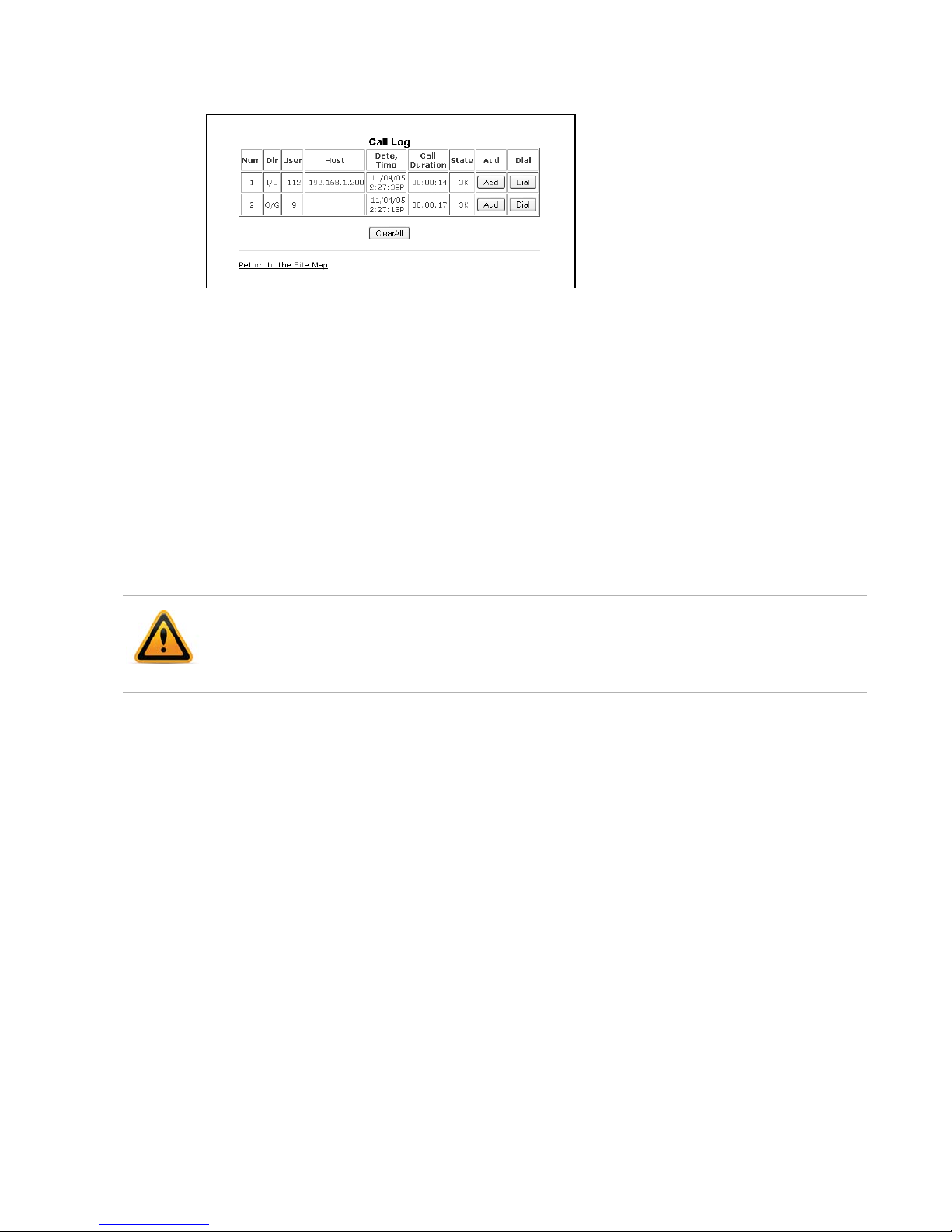
Call Log
The Call Log page provides a list of all calls (incoming, outgoing or missed) for the extension.
The log is organized to show the type of call — IC (incoming/received), OG (Outgoing) and M
(Missed), the contact name and contact information, date and time, duration, and state of the
call — Connected (OK), no call established (NOK). From the Call log, the user can call a contact
or store a record directly to the Phone Book.
To add a number from the Call Log to the Phone Book list:
• Select the Add button.
• If an Access Code Prefix, such as a Hunt Group, has been programmed into the phone, then
it will be inserted when an outbound call is placed from the Phone Book. Do not add to the
phone book entry.
To delete all Call logs:
• Select the ClearAll button.
Selecting the ClearAll button will delete all records in the Call Log.
To call a party from the Call Log:
• Click the Dial button associated with the desired Call log record. If an Access Code Prefix,
such as a Hunt Group, has been programmed into the phone, then it will automatically be
inserted when dialed.
Fortinet Technologies Inc. Page 60 FON-450i and FON-550i Telephones User Guide
Page 68

Network Time Configuration
The Network Time Configuration page allows you to configure the parameters required for
proper maintenance of the time and date on the phone. If provisioned by FortiVoice, nothing
needs to be changed on this page.
Configurable Parameters
• SNTP Server Address: Enter the URL or IP address of the SNTP server that will be used to
synchronize the date and time for the phone. Example: time.nrc.ca
• Time Zone: Select the time zone that matches the location of the phone.
• DST (Daylight Savings Time): Enable DST if applicable in your region. Ensure DST
configuration parameters are properly configured for the start and end of the DST cycle.
• Time Format: Sets the format of the LCD time display. Options include: Off, 12-hour or
24-hour.
• Date Format: Permits the configuration of the date format as will be shown on the LCD of the
phone.
• DST Configuration: If DST is enabled, then rules for when it is engaged and disengaged need
to be configured. DST can be configured to start and end on specific dates or switch
according to a day of the week in a certain month (typically used in North America).
Fortinet Technologies Inc. Page 61 FON-450i and FON-550i Telephones User Guide
Page 69

Known public SNTP servers that can be used:
— ntp.nasa.gov
— pool.ntp.org
— tick.ucla.edu
— time.nrc.ca
• To modify parameters on the Network Time screen, select the desired parameter and enter
new values or select values from the drop-down menus. When complete, press the Save
button.
Upgrade Configuration
If using with FortiVoice, these parameters should never need to be altered. When performing a
firmware update, refer to the phone system management software. Go to Tools > Update
Phones and follow the instructions.
On the Upgrade Configuration page, the results of the most recent download attempt are
displayed at the top. In addition, the following parameters can be modified:
• TFTP/HTTPS: Select the protocol that will be used to connect to the server where
configuration and software files are stored.
Fortinet Technologies Inc. Page 62 FON-450i and FON-550i Telephones User Guide
Page 70

• TFTP Server Address: Enter the IP address or FQDN of the TFTP server where configuration
and firmware files are located. Select the Received by DHCP on boot checkbox if the phone
will use DHCP option 66 or 150 to populate this field.
• HTTPS URL: is the URL of the HTTP/HTTPS server where configuration and software files
are located. Select the Received by DHCP on boot checkbox if the phone will use the DHCP
Option defined to retrieve the URL. If the option is present, the provisioning type is changed
automatically to HTTP/HTTPS using the URL from the DHCP option and default option 160.
Note: Port 80 is used for HTTP and 443 for HTTPS.
• ID: If required, enter the user name for HTTPS authentication.
• Password: If required, enter the password for HTTPS authentication
• MAC Cfg. Format: Define the format of the MAC (phone specific) configuration filename.
$MAC is replaced with the MAC address of the phone and must be included as part of the
file name or path to the configuration file on the HTTP/HTTPS server.
• Verifying Cert.: Enables the verification of the Certificate of Authority (CA) on the HTTPS
server. When enabled, the phone checks the CA signature. When Server name verification is
checked, the phone checks whether the name of the server sending the CA is valid. When
Expiration is checked, the phone checks the certification expiration date.
• Root CA: Defines a Certificate of Authority (CA) other than the internal CAs, which include
Verisign®, to use for verifying the CA from the server. When the CA is not available in the
phone memory, paste the Root CA in this area of web page.
• File to Upgrade: Select the S/W checkbox if the phone should check for new firmware files
on bootup. Select the Configuration checkbox if the phone should check and download
during bootup. We recommend you leave both enabled. If no new files are found, no
changes are made.
• Decryption Key: If required, enter the hexadecimal key required to decrypt configuration
files.
• Smart Upgrade: Enables periodic checks for new software on the provisioning server. Two
methods of smart upgrade are available; one checks the server at the interval in hours, the
second checks daily at the time specified in a 24-hour clock format. Select enable from the
Use Smart Upgrade drop-down menu, then select the method with the radial button and
enter the interval or time as appropriate.
If the phone finds a new version of software during the smart upgrade, the phone either
downloads the file or displays the availability of the new version and awaits confirmation to
download. To await confirmation, select the If discovered, confirm downloading checkbox.
To modify the configuration:
• Select the parameter and enter the new value or select the checkbox.
• When complete, press the Save button.
If the Received by DHCP on boot box is checked and there is an address specified for TFTP or
HTTPS, then it is ignored since the server information retrieved from the DHCP server is used.
Changes made to the Upgrade section require a reboot of the phone.
Fortinet Technologies Inc. Page 63 FON-450i and FON-550i Telephones User Guide
Page 71

QoS Configuration
Only make adjustments if you understand how these features work.
Diffserv Configuration
DiffServ Code Point (DSCP) or ToS establishes the priority of voice packets. Compatible routers
apply the DSCP for packet priority, handling higher priority packets first. However, at congested
routers, higher priority packets are discarded first. Thus, a median value for DSCP is
recommended.
IEEE 802.1Q
The VLAN tag defines the priority for Ethernet frames and the VLAN ID based on IEEE 802.1p/q.
If using with FortiVoice phone systems, 802.1p/q tagging is not currently supported. The phone
PC and LAN (voice) ports use separate VLAN tags. With a VLAN ID assigned, only frames with
the ID are accepted and frames sent from the phone include the LAN port ID and priority. In
addition, the PC, LAN ports and the default gateway must be assigned to employ the VLAN
tags for proper operation.
Jitter Buffer Configuration
A jitter buffer stores incoming packets to allow for re-sequencing of packets received out of
order. The jitter buffer configuration controls the size of the buffer used. The minimum, normal
and maximum delays expected can be changed. Using larger values produce less packet loss
as the phone waits longer to receive packets before processing. Note that large values may
delay voice packet processing and smaller values may produce more packet loss but quicker
voice packet processing. We recommend you use the default settings.
• When done making changes, press the Save button.
Modifications made to the IEEE 802.1p/Q configuration require a reboot of the phone.
If CDP is enabled, manual VLAN settings are overwritten during a reboot of the phone. To use
manually defined VLAN settings, disable CDP.
Fortinet Technologies Inc. Page 64 FON-450i and FON-550i Telephones User Guide
Page 72

Load Default
The Load Default page provides an option to return the phone configuration to factory default
values.
To set the phone to the default configuration:
• Select the Load button. Note: All settings will be lost!
• The phone will load the default configuration and automatically reboot.
Reboot
To reboot the phone:
• Select the Reboot button.
• The phone will reboot.
Fortinet Technologies Inc. Page 65 FON-450i and FON-550i Telephones User Guide
Page 73

Using the FON-450i/FON-550i Phone
Receiving a Call
When you receive a call, the phone rings while the LCD displays the incoming call information
and the associated extension button flashes.
To answer an incoming call:
• Lift the handset. You may press the button, line button or the Answer softkey to activate
the speakerphone. To use a headset, press the headset button.
To end a call:
• Hang up the handset. If using the speakerphone, press the button. If using the headset,
press the button.
To refuse a call:
• Press the Refuse softkey. The phone system or service will handle the call according to the
‘busy’ settings.
Placing a Call
Calls can be placed with the handset on-hook or off-hook. This is similar to a mobile phone. The
phone supports a technique called ‘store and forward dialing’. After you dial a digit, the IP
phone waits about 5 seconds for additional digits. If you do not dial additional digits, the phone
sends the digits you dialed to the phone system for processing. When done dialing, press the
Dial softkey or ?key to place the call immediately.
To place a call:
• Lift the handset or press the button or line button to activate the speakerphone. To use a
headset, press the button.
• Dial the destination number. After a short delay, the phone will send the number. Optionally,
press the Dial softkey or press ?to place the call immediately.
• When connected to the remote party, the LCD displays the elapsed call time and provides
softkey options for call control.
To end a call:
• Hang up the handset. If using the speakerphone, press the button. If using the headset,
press the button.
Fortinet Technologies Inc. Page 66 FON-450i and FON-550i Telephones User Guide
Page 74

Putting a Call on Hold
When placing a call on hold, the held party cannot hear you and you will not hear the held party.
The held party will hear MOH (Music On Hold), if configured with the phone system.
While a call is on hold, you can answer or place other calls and can toggle between held calls on
the same dedicated extension key. With Call Hold Ringback enabled, the phone rings as a
reminder of calls on hold when you hang up after completing the other call.
To place a call on hold:
• Press the button or the Hold softkey. The call status changes to hold and you receive
dial tone. You can then select another line to answer or place a call.
To toggle between two calls on the same line:
• Press the button or the Resume softkey.
To retrieve a call held on a different line:
• Press the flashing flexible key associated with the call on hold.
Attended Call Transfer
Calls can be announced to a transfer party before making the transfer.
To transfer an active call:
• Press the button or the Transfer softkey. The active call status changes to hold and you
receive dial tone to dial an alternate extension/number.
• Dial the extension or phone number, or press a preprogrammed flexible key linked to an
extension.
• Wait for the remote party to answer and announce the transfer.
• Hang up the handset to complete the transfer, or press the EndCall softkey to cancel the
transfer.
Blind Call Transfer
You can transfer an active call to another extension without talking to the party receiving the
call. The call transfers to the new party without verifying that the new party is there or willing to
receive the call.
To transfer a call without announcing the transfer
Manual method
• Press the Transfer softkey.
• Dial the extension or phone number, or press a preprogrammed flexible key linked to an
extension.
• Hang up the handset to complete the transfer, or press the EndCall softkey to cancel the
transfer.
Simple method
If flexible keys are programmed to monitor extensions, the blind transfer process becomes a
one-touch process.
• To blind transfer while on a call, simply press a flexible key associated with an extension and
the call is transferred.
Fortinet Technologies Inc. Page 67 FON-450i and FON-550i Telephones User Guide
Page 75

3-Party Conference
The phone supports conferencing with two other parties. There are 2 methods for setting up a
conference.
Method 1: Setting up a conference call
• Place the first call.
• Press the Right navigation button to scroll to the next softkey option, then press the Conf
softkey to place the first call on hold and get dial tone.
• Dial the second party for the conference, then press the Dial softkey.
• When the party answers, press the Join softkey to join all parties into a conference call.
Method 2: Conferencing a second person with first person already on hold
• With one caller already on hold and the second call in progress, simply press the Right
navigation button twice to scroll to the next softkey option, then press the Join softkey to
establish the conference.
Ending a conference call
To end a conference and disconnect all parties:
• Hang up the handset or press the EndCall softkey.
Call Waiting
Redial
If the extension is configured in the phone system for Call Waiting, while on a call, the line
button flashes and a beep tone is played to you over the active conversation to indicate the new
call. In addition, the LCD displays the incoming Caller ID so you know who is calling before
deciding to interrupt the current call.
To answer an incoming call while on a call:
• Press the Answer softkey. The first call will be placed on hold and you will be connected to
the second caller.
The FON-450i/FON-550i saves the last number dialed and allows you to redial the number with
the touch of a button.
To redial a call:
• Press the Redial softkey. The phone activates the speakerphone and places the call.
• For privacy, lift the handset or press the button, then press the Redial softkey.
Fortinet Technologies Inc. Page 68 FON-450i and FON-550i Telephones User Guide
Page 76

Preprogrammed Speed Dial Keys
Flexible keys can be programmed by the administrator for system or personal speed dial use.
To place a call using a speed dial key:
• Press the desired flexible key preprogrammed as a speed dial. The phone activates the
speakerphone and places the call according to the outgoing line hunting rules programmed
in the phone system for the extension. You can also select a different line button on the
phone prior to selecting the speed dial key.
• For privacy prior to placing the call, lift the handset or press the button.
Dialing using a Speed Dial Number
The FON-450i/FON-550i has a Phone Book that can store up to 80 contacts. Each record
includes a name, contact information and a speed dial number (00–79). When you dial a speed
dial number, the phone initiates a call to the contact. By default, the speed dialing feature is
enabled. If disabled, this feature will not work.
To place a call using a speed dial number:
• Dial the speed dial number (00–79), then press the Dial softkey or press ?to place the call to
the desired contact. The phone will dial the number programmed in the phone book. If an
access code has been preprogrammed for the phone (example: 9 for gaining access to
outside lines), the access code will automatically be prepended to the programmed speed
dial entry for placing the call.
DND (Do Not Disturb)
When the DND (Do Not Disturb) feature is activated, the phone will not notify you of an incoming
call thus allowing you to work without interruptions from incoming calls. Calls will be routed
according to the settings programmed for your extension or service.
To activate DND:
• While the phone is idle, press the button. When active, the button LED illuminates red,
and Do not disturb is displayed on the LCD.
To deactivate DND:
• Press the illuminated button again.
Muting a Call
Mute toggles the microphone of the handset, speakerphone and headset off or on. When mute
is active, the connected party will not hear anything from the FON-450i/FON-550i.
To mute the microphone:
• Press the button. The button LED illuminates red indicating mute is active.
To unmute the microphone:
• Press the illuminated button again. The other person will hear audio once the mute LED
is off.
Fortinet Technologies Inc. Page 69 FON-450i and FON-550i Telephones User Guide
Page 77

Accessing Your Voicemail
When you have a message waiting, the Message LED flashes to indicate you have new
messages in your mailbox.
To access your voice mailbox:
• Press the button. The display indicates the number of new and old messages that reside
in your mailbox.
• To access the voicemail system, press the Dial softkey. Follow the instructions from your
voicemail system to listen to messages.
Alternatively, press the Vmail softkey to immediately access the voicemail system.
Line/Extension Appearance Coverage
The FON-450i/FON-550i has BLF/DSS line functionality that addresses the special needs
typically associated with an Attendant or Secretarial answering position but may be used for
any employee. Options to monitor lines, extensions or queues are programmed on a key-by-key
basis in the phone system.
The specific needs for these users are:
• Direct Station Selection (DSS) — one-touch calling and transfers to extensions.
• Busy Lamp Field (BLF) — visual status indication of lines, extensions or queues.
• Coverage — the ability to pick up calls ringing at monitored extensions.
To call an idle monitored extension:
• Press the flexible key associated with the extension you wish to call. For privacy, lift the
handset or press the button.
To blind transfer a call:
• Press the flexible key associated with the extension. The phone will transfer the call.
To answer a call ringing at a monitored extension:
• Press the flexible key associated with the extension that is ringing (flashing green). For
privacy, lift the handset or press the button.
Hotline/Warm-Line
With Hotline/Warm-Line operation configured, the FON-450i/FON-550i automatically calls the
defined destination when you take the handset off-hook or press the button. Hotline means
the call is made immediately, while warm-line provides a delay of up to 10 seconds before
placing the call. The latter provides time to access a system feature or line as might be required.
Note that with Hotline configured, speed dial, redial and other automated dialing features will
not operate.
Fortinet Technologies Inc. Page 70 FON-450i and FON-550i Telephones User Guide
Page 78

Using your FON-450i/FON-550i Phone
with FortiVoice
Access an outside line
Dial hunt group L or KA–KK (Americas, UK), dial : or KA–KK (other countries). No
hunt group is required if Direct Line Access is enabled. You can select a line directly if it has a
programmed key.
Accessing Features
If Direct Line Access is enabled, dial __ to access features indicated with a , unless you
are using a programmed key.
Do not disturb
Press the button to toggle on/off.
Pick up — Any ringing extension
Press the programmed Pickup key, or dial _L+ ?.
Pick up — Specific extension
Press the programmed key associated with the extension ringing or dial _J+ extension + ?.
Place a caller on hold
Press the button.
Retrieve a caller on hold
Press the button or press the flashing key associated with the call on hold.
Answer queued call
Press the flashing key associated with the call in the queue. Otherwise, dial J+ ? to retrieve
the next caller in your queue.
Answer FortiVoice call waiting
Press the Answer softkey or press the flashing line appearance key.
Screened transfer
Press the button + extension (or outside number) + ?. To complete the transfer, press the
Transfer softkey or hang up. To cancel transfer, press the EndCall softkey and then the Resume
softkey to connect to the caller on hold.
Blind transfer
Press the button + extension (or outside number) + Dial softkey, then hang up. If an
extension is tied to a programmable key, then during the call, press that key to transfer.
Voicemail transfer
Press the button + _ + extension + Dial softkey, then hang up.
Fortinet Technologies Inc. Page 71 FON-450i and FON-550i Telephones User Guide
Page 79

Conference call
Press the softkey then press the Conf. softkey to put the first party on hold. Call the second
party (for external calls, first access an outside line). Press the Join softkey to connect to all
parties.
Park a caller
Press the programmed Park key. Otherwise, press the button + _GA: + ?.
The system will respond with a parking orbit.
Retrieve a parked caller
At the dial tone, press the programmed UnPark key, then dial orbit + ?.
Otherwise, dial __ + orbit + ?.
Two-way intercom/group paging to FortiVoice phones
Press the programmed Intercom or Group Page key + extension + Dial softkey.
Otherwise dial _KF (Intercom) or _KG (Paging) + extension + ?.
PA overhead paging
Press the programmed Overhead Paging key, or dial _0 + ?.
Attach account code to last call
At dial tone, dial _KK + ?. When prompted, enter <Account code> + ?.
CDR logging must be active.
Voicemail
Access Mailbox — Locally Press the Vmail softkey or the button.
Access Mailbox — Remotely __ + <mailbox number>
Change greeting options S
Change personal options (password, date stamp, remote notification options) D
MESSAGE PLAYBACK CONTROLS
Rewind 10 seconds A
Go to beginning AA
Skip ahead 10 seconds D
Skip to end of message DD
Check time and date stamp G
Forward message H
Delete message J
Save message L
Skip to next message ?
Updating the Firmware
In the system management software, go to Tools > Update Phones and follow the instructions.
Fortinet Technologies Inc. Page 72 FON-450i and FON-550i Telephones User Guide
Page 80

Troubleshooting
Information
The FON-450i/FON-550i phone provides the means to quickly view the network parameters (IP
address, default gateway address, and subnet-mask), server IP addresses (SIP servers, TFTP
server, and SNTP server), results of the last file download attempt, boot version, and hardware
and firmware version. This information may be useful if calling Fortinet Support.
• Press the button, then select 8. Information.
• Press the Up or Down softkeys to scroll through the parameters.
FON-550i screen
• Press the button to exit the menu.
Fortinet Technologies Inc. Page 73 FON-450i and FON-550i Telephones User Guide
Page 81

Troubleshooting Guide
Symptom Corrective Action
LCD Off 1. Ensure PoE cable or power adapter is properly connected.
Handset off-hook, no dial tone 1. Ensure the RJ-45 cable is correctly connected.
2. Check/replace AC/DC adapter.
2. Make sure that the SIP Server IP Address is correct.
Button LEDs flash
alternating red/yellow
Phone is stuck displaying
“Obtaining IP Address”
No audio during a call If the phone is outside the LAN where the phone system
The phone has locked up or
the screen is blank but there
is power.
Line not registered with the SIP server (FortiVoice phone
system)
1. Check the SIP configuration parameters are correct.
2. Check network connections.
3. Check the phone system / SIP server is operational.
The DHCP server is not responding.
1. Check the DHCP server is functional.
2. If enabled, check VLAN settings.
To exit the DHCP searching mode, press the button
3 times to complete the bootup. Manually assign an IP
address or reboot the phone to try having the DHCP
server assign an IP address.
resides, then ensure the proper ports are open on the firewall
to ensure calls can make it through.
A phone lock-up may be caused by a communications error
during a firmware upgrade. To correct this problem:
1. Disconnect power from the phone.
2. Press and hold the volume up and S button while
re-applying power.
3. Release the buttons when the Message LED in the top
corner turns off.
4. When the BootC screen appears, enter the digits A, S,
D, F.
5. Follow the prompts to configure IP parameters for the
phone.
6. At the Server Addr? prompt, enter the TFTP server
address where the phone can find the firmware files. If
already correct, press the Next softkey.
7. At the Do you want to apply default? prompt, select the
Yes softkey to use defaults or No softkey to use previously
assigned parameters.
Fortinet Technologies Inc. Page 74 FON-450i and FON-550i Telephones User Guide
The phone will reboot, perform the update and return to
normal operation.
Page 82

Appendix A. Specifications
— FON-450i/FON-550i
Hardware Specifications
Item FON-450i/FON-550i
Network Interface RJ-45 IEEE 802.3 Ethernet/Fast Ethernet switch port
PC/Workstation Interface RJ-45 IEEE 802.3 Ethernet/Fast Ethernet switch port
Power 802.3af or AC/DC power adapter
Message indicator, speakerphone, mute, DND, headset, red
LEDs
LED Indicators
LCD
Physical Size (H x W x D)
Weight 1.3 Kg
AC/DC Adapter
Operation Temperature 0 – 40° C
Storage Temperature -20 – 60° C
Operation Humidity 10 – 85% RH, non-condensing
Audio Acoustic Echo Canceller & Voice Active Detection
10 programmable buttons with multi-colored LEDs
(FON-450i)
22 programmable buttons with multi-colored LEDs
(FON-550i)
240 x 42 dot graphic (FON-450i)
240 x 56 dot graphic (FON-550i)
20.8 x 22.3 x 10.5 cm
8.1 x 9.25 x 2 inches
Output: 48VDC, 0.3A (max.)
Input: 100-240 VAC, 50/60 Hz.
Codecs G.711, G.723.1/a, G.729a, and G.722
Fortinet Technologies Inc. Page 75 FON-450i and FON-550i Telephones User Guide
Page 83

Appendix B. Character Table for
Dial Pad Model
The FON-450i/FON-550i supports a special character mode for en terni ng non-numeric
characters. The table below covers all possible character options.
Digit DIal Pad Mode
Upper Case
‘[A]’
1 @ : / @ : / @ : /
2 A B C a b c | $ %
3 D E F d e f ^ & _
4 G H I g h i ( ) ?
5 J K L j k l - + , /
6 M N O m n o < > =
7 P Q R S p q r s ; :
8 T U V t u v ’ ” `
9 W X Y Z w x y z { }
0 . , ? ! . , ? ! . , ? !
* . * . * . *
# Space (‘ ‘) Space (‘ ‘) # [ ]
Lower Case
‘[a]’
Symbols
‘[*]’
Fortinet Technologies Inc. Page 76 FON-450i and FON-550i Telephones User Guide
Page 84

Regulatory and Safety Notices
Radio Frequency Emissions
FCC Compliance Statement
This device complies with Part 15 rules. Operation is subject to the following two conditions:
1. This device may not cause harmful interference, and
2. This device must accept any interference received, including interference that may cause
undesired operation.
This equipment has been tested and found to comply with the limits for a Class B digital device,
pursuant to Part 15 of the FCC rules. These limits are designed to provide reasonable protection
against harmful interference in a residential installation. This equipment generates, uses and
can radiate radio frequency energy and, if not installed and used in accordance with the
instructions, may cause harmful interference to radio communications. However, there is no
guarantee that interference will not occur in a particular installation. If this equipment does
cause harmful interference to radio or television reception, which can be determined by turning
the equipment off and on, the user is encouraged to try to correct the interference by one of the
following measures:
• Reorient or relocate the receiving antenna.
• Increase the separation between the equipment and the receiver.
• Connect the equipment into an outlet on a different circuit from that to which the receiver
is connected.
If problems persist, consult the dealer or an experienced radio/TV technician for help.
Canadian Compliance Statement
This Class B digital apparatus complies with Canadian ICES-003.
Cet appareil numérique de la classe B est conforme à la norme NMB-003 du Canada.
This device complies with Class B Limits of Industry Canada. Operation is subject to the
following two conditions:
1. This device may not cause harmful interference, and
2. This device must accept any interference received, including interference that may cause
undesired operation.
European Union Declarations of Conformity
Fortinet declares that the equipment specified in this document, which bears the “CE” mark,
conforms to the European Union Radio and Telecommunications Terminal Equipment Directive
(R&TTE 1999/5/EC) including,
• Electromagnetic Compatibility Directive (89/336/EEC) and
• Low Voltage Directive (73/23/EEC)
The product fulfills the essential requirements of the harmonized standards shown above.
Fortinet Technologies Inc. Page 77 FON-450i and FON-550i Telephones User Guide
Page 85

Product Safety Instructions
This product complies with and conforms to the following international Product Safety
standards as applicable:
• Safety of Information Technology Equipment, IEC 60950-1, including
• Relevant national deviations as listed in Compliance with IEC for Electrical
Equipment (IECEE)
• Safety of Information Technology Equipment, CAN/CSA-C22.2 No. 60950-1/UL 60950-1
E-911 and use of the FON-450i/FON-550i with Multi-Line
Telephone Systems
Please note the use and operation of this phone as part of a multi-line telephone system (MLTS)
may be subject to state and/or federal E-911 MLTS laws that require the MLTS to provide a
caller’s telephone number, extension, and physical location to applicable state and/or local
emergency services when a caller initiates a 911 call. The MLTS may not provide a caller’s
telephone number, extension, or physical location information to emergency services when a
caller dials 911, and compliance with state and/or federal E-911 MLTS laws is the sole
responsibility of the purchaser of this phone.
Privacy
FON-450i/FON-550i implements security and encryption technologies. However, privacy of
communications may not be ensured when using this telephone.
Fortinet Technologies Inc. Page 78 FON-450i and FON-550i Telephones User Guide
Page 86

Limited Warranty
For detailed warranty information, please visit Fortinet Technical Support at:
http://www.fortinet.com/fortivoice
Warranty Repair Services
Should the set fail during the warranty period:
• In North America, please call 1-866-393-9960 for further information.
• Outside North America, contact your sales representative for return instructions.
You will be responsible for shipping charges, if any. When you return this telephone for warranty
service, you must present proof of purchase.
Fortinet Technologies Inc. Page 79 FON-450i and FON-550i Telephones User Guide
Page 87

 Loading...