

Page 1
Page 2
Page 3

3
TABLE OF CONTENTS
Warranty ..............................................2
Safety Summary ..................................4
Safety Information ..............................4
Shock Hazards ..................................5
Flash Hazards ....................................5
Fire Hazards ......................................6
Fume Hazards....................................7
Additional Safety Information ............8
Welder Specifications ........................9
Description ........................................9
Duty Cycle ..........................................9
Internal Thermal Protection ................9
Know Your Welder ..............................10
Welder Installation ..............................11
Power Source Connection ................11
Extension Cords ..............................11
Assembling the Welder ......................11
Unpacking the Welder......................11
Packing List......................................11
Installing the Handle ........................11
Assemble the Face Shield ..............12
Selecting the Welding Wire..............12
Installing the Welding Wire ..............12
Operation ............................................14
Controls and Indicators ......................14
Power Switch ..................................14
Voltage Selector ..............................14
Preparations for Welding....................14
Setting Up the Workpiece ................14
Preparing the Joint ..........................14
Ground Clamp Connection ..............15
Learning to Weld ................................16
Holding the Gun ................................16
Welding Techniques ..........................17
Moving the Gun................................17
Types of Weld Beads ......................17
Welding Positions ............................18
Multiple Pass Welding......................19
Special Welding Methods ................19
Spot Welding..................................19
Maintenance ........................................20
General ..............................................20
Consumable Maintenance..................20
Maintaining the Contact Tip................20
Maintaining the Nozzle ......................21
Testing for a Shorted Nozzle..............21
Replace a Gun Liner ..........................21
Troubleshooting..................................23
Wiring Diagram....................................24
Parts List ..............................................25
Suggested Settings ............................29
Page 4
4
TABLE OF CONTENTS
Every welder respects the tools with which
they work. They know that the tools represent years of constantly improved designs
and developments. The true craftsman also
knows that tools are dangerous if misused or
abused.
Reading this operator’s manual before using
the welder will enable you to do a better,
safer job. Learn the welder’s applications
and limitations as well as the specific potential hazards peculiar to welding.
IMPORTANT SAFETY INFORMATION
The following safety information is provided
as guidelines to help you operate your new
welder under the safest possible conditions.
Any equipment that uses electrical power
can be potentially dangerous to use when
safety or safe handling instructions are not
known or not followed. The following safety
information is provided to give the user the
information necessary for safe use and
operation.
A procedure step preceded by a WARNING
is an indication that the next step contains a
procedure that might be injurious to a person
if proper safety precautions are not heeded.
A procedure preceded by a CAUTION is an
indication that the next step contains a procedure that might damage the equipment
being used.
A NOTE may be used before or after a procedure step to highlight or explain something
in that step.
READ ALL SAFETY INSTRUCTIONS
CAREFULLY before attempting to install,
operate, or service this welder. Failure to
comply with these instructions could result in
personal injury and/or property damage.
RETAIN THESE INSTRUCTIONS FOR
FUTURE REFERENCE.
Note:
• The following safety alert symbols identify
important safety messages in this manual.
• When you see one of the symbols shown
here, be alert to the possibility of personal
injury and carefully read the message that
follows.
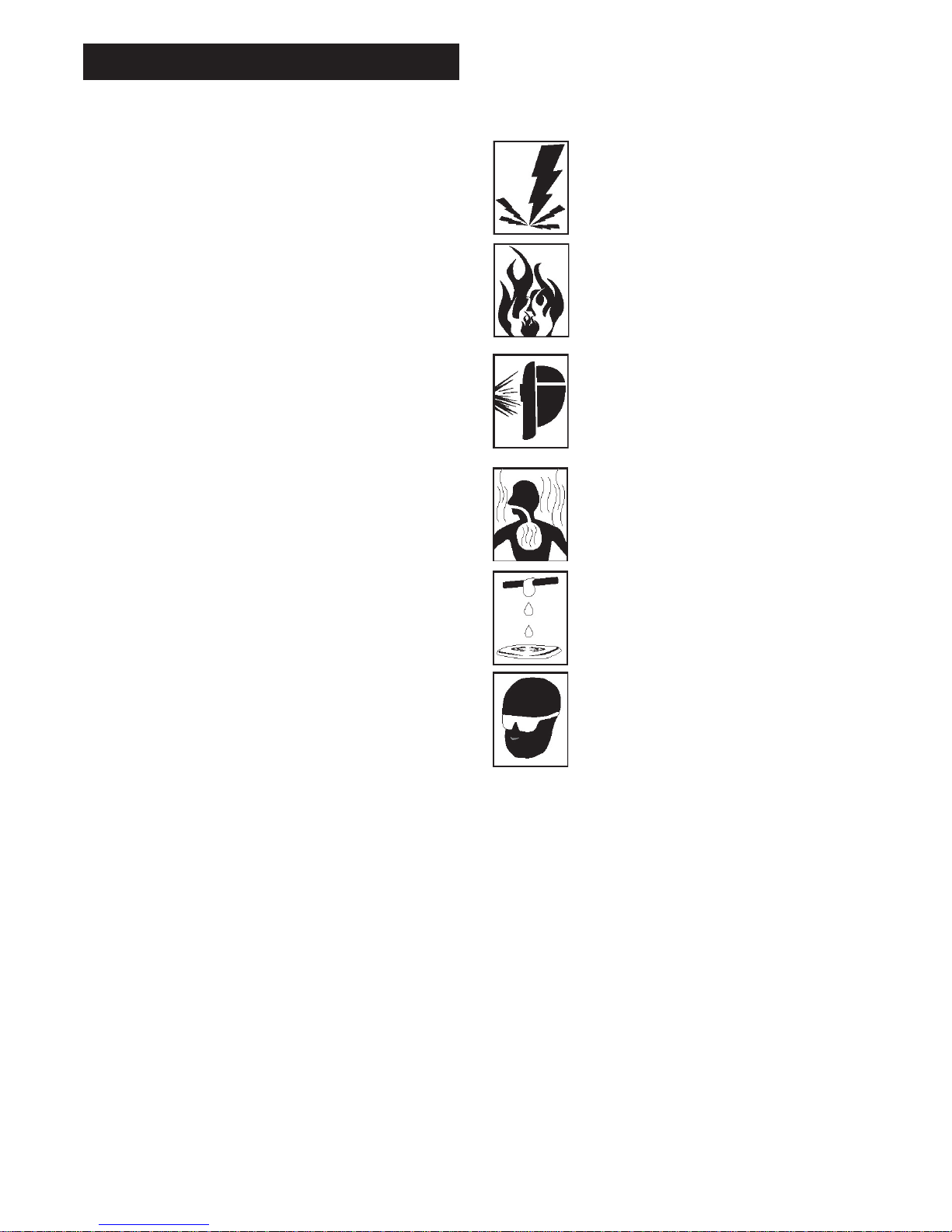
This symbol indicates that the possibility of electric shock hazard
exists during the operation of the
step(s) that follow.
This symbol indicates that the possibility of fire hazard exists during
the operation of the step(s) that
follow.
This symbol indicates that the helmet must be worn during the
step(s) that follow to protect
against eye damage and burns
due to flash hazard.
This symbol indicates that the possibility of toxic gas hazard exists
during operation of the step(s) that
follow.
This symbol indicates that the possibility of being burned by hot slag
exists during operation of the
step(s) that follow.
This symbol indicates that the eye
protection should be worn to protect against flying debris in the following step(s).
• Published standards on safety are avail-
able. They are listed in ADDITIONAL
SAFETY INFORMATION at the end of this
SAFETY SUMMARY.
The National Electrical Code, Occupation
Safety and Health Act regulations, local
industrial codes and local inspection requirements also provide a basis for equipment
installation, use, and service.
SAFETY SUMMARY
Page 5
5
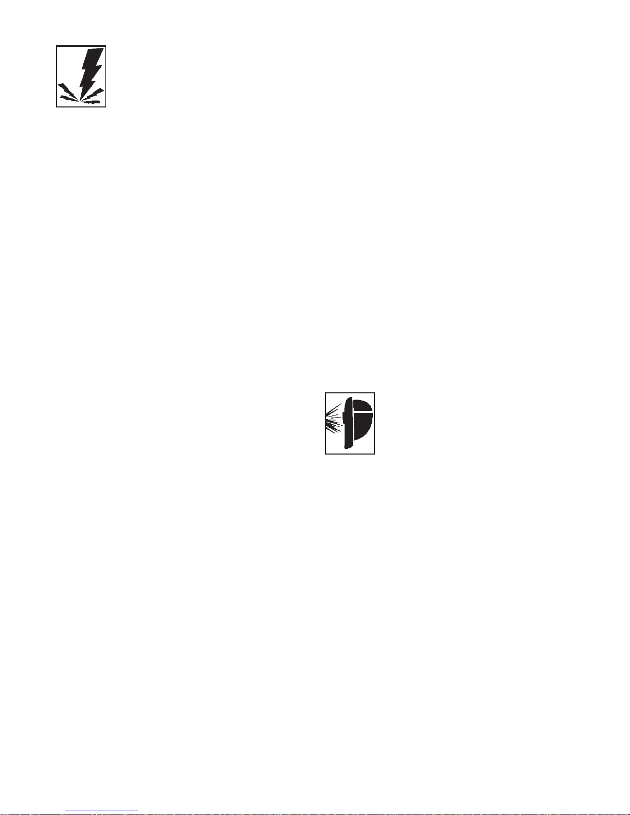
SHOCK HAZARD
WARNING
ELECTRIC SHOCK CAN KILL! To reduce
the risk of death or serious injury from shock,
read, understand, and follow the following
safety instructions. In addition, make certain
that anyone else who uses this welding
equipment, or who is a bystander in the
welding area understands and follows these
safety instructions as well.
• IMPORTANT! TO REDUCE THE RISK
OF DEATH, INJURY, OR PROPERTY
DAMAGE, DO NOT ATTEMPT OPERATION of this welding equipment until you
have read and understand the following
safety summary.
• Do not, in any manner, come into physical contact with any part of the welding
current circuit. The welding current circuit
includes:
a. the work piece or any conductive
material in contact with it,
b. the ground clamp,
c. the electrode or welding wire,
d. any metal parts on the electrode
holder, or wire feed gun.
• Do not weld in a damp area or come in
contact with a moist or wet surface.
• Do not attempt to weld if any part of
clothing or body is wet.
• Do not allow the welding equipment to
come in contact with water or moisture.
• Do not drag welding cables, wire feed
gun, or welder power cord through or
allow them to come into contact with
water or moisture.
• Do not touch welder, attempt to turn
welder on or off if any part of the body or
clothing is moist or if you are in physical
contact with water or moisture.
• Do not attempt to plug the welder into the
power source if any part of body or clothing is moist, or if you are in physical contact with water or moisture.
• Do not connect welder work piece clamp
to or weld on electrical conduit.
• Do not alter power cord or power cord
plug in any way.
• Do not attempt to plug the welder
into the power source if the ground prong
on power cord plug is bent over, broken
off, or missing.
• Do not allow the welder to be connected
to the power source or attempt to weld if
the welder, welding cables, welding site,
or welder power cord are exposed to any
form of atmospheric precipitation, or salt
water spray.
• Do not carry coiled welding cables around
shoulders, or any other part of the body,
when they are plugged into the welder.
• Do not modify any wiring, ground
connections, switches, or fuses in this
welding equipment.
• Wear welding gloves to help insulate
hands from welding circuit.
• Keep all liquid containers far enough
away from the welder and work area so
that if spilled, the liquid can not possibly
come in contact with any part of the
welder or electrical welding circuit.
• Replace any cracked or damaged parts
that are insulated or act as insulators
such as welding cables, power cord, or
electrode holder IMMEDIATELY.
FLASH HAZARDS
WARNING
ARC RAYS CAN INJURE EYES AND
BURN SKIN! To reduce the risk of injury
from arc rays, read, understand, and follow
the following safety instructions. In addition,
make certain that anyone else that uses this
welding equipment, or is a bystander in the
welding area understands and follows these
safety instructions as well. Headshields and
filter should conform to ANSI Z87.1 standards.
• Do not look at an electric arc without proper
protection. A welding arc is extremely bright
and intense and, with inadequate or no eye
protection, the retina can be burned, leaving a permanent dark spot in the field of
vision. A shield or helmet with a number 10
shade filter lens (minimum) must be used.
• Do not strike a welding arc until all
bystanders and you (the welder) have
welding shields and/or helmets in place.
• Do not wear a cracked or broken
Page 6
6
helmet and replace any cracked or broken filter lenses IMMEDIATELY.
• Do not allow the uninsulated portion
of the wire feed gun to touch the ground
clamp or grounded work to prevent an
arc flash from being created on contact.
• Provide bystanders with shields or helmets fitted with a #10 shade filter lens.
• Wear protective clothing. The intense
light of the welding arc can burn the skin
in much the same way as the sun, even
through light-weight clothing. Wear dark
clothing of heavy material. The shirt worn
should be long sleeved and the collar
kept buttoned to protect chest and neck.
• Protect against REFLECTED ARC RAYS.
Arc rays can be reflected off shiny surfaces such as a glossy painted surface,
aluminum, stainless steel, and glass. It is
possible for your eyes to be injured by
reflected arc rays even when wearing a
protective helmet or shield. If welding with
a reflective surface behind you, arc rays
can bounce off the surface, then off the filter lens on the inside of your helmet or
shield, then into your eyes. If a reflective
background exists in your welding area,
either remove it or cover it with something
non-flammable and non-reflective.
Reflective arc rays can also cause skin
burn in addition to eye injury.
FIRE HAZARDS
WARNING
FIRE OR EXPLOSION CAN CAUSE
DEATH, INJURY, AND PROPERTY DAMAGE! To reduce the risk of death, injury, or
property damage from fire or explosion, read,
understand, and follow the following safety
instructions. In addition, make certain that
anyone else that uses this welding equipment, or is a bystander in the welding area,
understands and follows these safety instructions as well. REMEMBER! Arc welding by
nature produces sparks, hot spatter, molten
metal drops, hot slag, and hot metal parts that
can start fires, burn skin, and damage eyes.
• Do not wear gloves or other clothing that
contains oil, grease, or other flammable
substances.
• Do not wear flammable hair preparations.
• Do not weld in an area until it is checked
and cleared of combustible and/or flammable materials. BE AWARE that sparks
and slag can fly 35 feet and can pass
through small cracks and openings. If
work and combustibles cannot be separated by a minimum of 35 feet, protect
against ignition with suitable, snug-fitting,
fire resistant, covers or shields.
• Do not weld on walls until checking for
and removing combustibles touching the
other side of the walls.
• Do not weld, cut, or perform other such
work on used barrels, drums, tanks, or
other containers that had contained a
flammable or toxic substance. The techniques for removing flammable substance and vapors, to make a used container safe for welding or cutting, are
quite complex and require special education and training.
• Do not strike an arc on a compressed
gas or air cylinder or other pressure vessel. Doing so will create a brittle area that
can result in a violent rupture immediately or at a later time as a result of rough
handling.
• Do not weld or cut in an area where the
air may contain flammable dust (such as
grain dust), gas, or liquid vapors (such as
gasoline).
• Do not handle hot metal, such as the
work piece or electrode stubs, with bare
hands.
• Wear leather gloves, heavy long sleeve
shirt, cuffless trousers, high-topped
shoes, helmet, and cap. As necessary,
use additional protective clothing such as
leather jacket or sleeves, fire resistant
leggings, or apron. Hot sparks or metal
can lodge in rolled up sleeves, trouser
cuffs, or pockets. Sleeves and collars
should be kept buttoned and pockets
eliminated from the shirt front.
• Have fire extinguisher equipment handy
for immediate use! A portable chemical
fire extinguisher, type ABC, is recommended.
• Wear ear plugs when welding overhead to
prevent spatter or slag from falling into ear.
• Make sure welding area has a good,
solid, safe floor, preferably concrete or
masonry, not tiled, carpeted, or made of
Page 7
7
any other flammable material.
• Protect flammable walls, ceilings, and
floors with heat resistant covers or
shields.
• Check welding area to make sure it
is free of sparks, glowing metal or slag,
and flames before leaving the welding
area.
FUME HAZARDS
WARNING
FUMES, GASSES, AND VAPORS CAN
CAUSE DISCOMFORT, ILLNESS, AND
DEATH! To reduce the risk of discomfort, ill-
ness, or death, read, understand, and follow
the following safety instructions. In addition,
make certain that anyone else that uses this
welding equipment or is a bystander in the
welding area, understands and follows these
safety instructions as well.
• Do not weld in an area until it is checked
for adequate ventilation as described in
ANSI standard #Z49.1. If ventilation is
not adequate to exchange all fumes and
gasses generated during the welding
process with fresh air, do not weld unless
you (the welder) and all bystanders are
wearing air-supplied respirators.
• Do not heat metals coated with, or that
contain, materials that produce toxic
fumes (such as galvanized steel), unless
the coating is removed. Make certain the
area is well ventilated, and the operator
and all bystanders are wearing air-supplied respirators.
• Do not weld, cut, or heat lead, zinc, cadmium, mercury, beryllium, or similar metals without seeking professional advice
and inspection of the ventilation of the
welding area. These metals produce
EXTREMELY TOXIC fumes which can
cause discomfort, illness, and death.
• Do not weld or cut in areas that are near
chlorinated solvents. Vapors from chlorinated hydrocarbons, such as trichloroethylene and perchloroethylene, can be
decomposed by the heat of an electric
arc or its ultraviolet radiation. These
actions can cause PHOSGENE, a HIGH-
LY TOXIC gas to form, along with other
lung and eye-irritating gasses. Do not
weld or cut where these solvent vapors
can be drawn into the work area or
where the ultraviolet radiation can penetrate to areas containing even very small
amounts of these vapors.
• Do not weld in a confined area unless it
is being ventilated or the operator (and
anyone else in the area) is wearing an
air-supplied respirator.
• Stop welding if you develop momentary
eye, nose, or throat irritation as this indicates inadequate ventilation. Stop work
and take necessary steps to improve
ventilation in the welding area. Do not
resume welding if physical discomfort
persists.
WARNING
This product contains chemicals, including
lead, or otherwise produces chemicals
known to the State of California to cause
cancer, birth defects and other reproductive
harm. Wash hands after Handling.
(California Health & Safety Code Sec.
25249.5 et seq.)
Page 8

8
ADDITIONAL SAFETY INFORMATION
For additional information concerning welding safety, refer to the following standards
and comply with them as applicable.
• ANSI Standard Z49.1 – SAFETY IN
WELDING AND CUTTING – obtainable
from the American Welding Society, 550
NW Le Jeune Road, Miami, FL 33126
Telephone (800) 443-9353, Fax (305)
443-7559 – www.amweld.org or
www.aws.org
• ANSI Standard Z87.1 – SAFE PRACTICE FOR OCCUPATION AND EDUCATIONAL EYE AND FACE PROTECTION
– obtainable from the American National
Standards Institute, 11 West 42nd St.,
New York, NY 10036 Telephone (212)
642-4900,
Fax (212) 398-0023 – www.ansi.org
• NFPA Standard 51B – CUTTING AND
WELDING PROCESS – obtainable from
the National Fire Protection Association,
1 Batterymarch Park, P.O. Box 9101,
Quincy, MA 02269-9101 Telephone (617)
770-3000
Fax (617) 770-0700 – www.nfpa.org
• OSHA Standard 29 CFR, Part 1910,
Subpart Q., WELDING, CUTTING AND
BRAZING – obtainable from your state
OSHA office or U.S. Dept. of Labor
OSHA, Office of Public Affairs, Room
N3647, 200 Constitution Ave.,
Washington, DC 20210 – www.osha.gov
• CSA Standard W117.2 – Code for SAFETY IN WELDING AND CUTTING. –
obtainable from Canadian Standards
Association, 178 Rexdale Blvd.,
Etobicoke, Ontario M9W 1R3 –
www.csa.ca
• American Welding Society Standard
A6.0. WELDING AND CUTTING CONTAINERS WHICH HAVE HELD COMBUSTIBLES. – obtainable from the
American Welding Society, 550 NW Le
Jeune Road, Miami, FL 33126 Telephone
(800) 443-9353, Fax (305) 443-7559 –
www.amweld.org or www.aws.org
Page 9

9
WELDER SPECIFICATIONS
DESCRIPTION
Your new flux core (FCAW) wire feed welder
is designed for maintenance and sheet metal
fabrication. The welder consists of a singlephase power transformer, and a unique builtin control/feeder. This welder is capable of
welding with 0.030 (0.8mm) and 0.035
(0.9mm) self-shielding flux-core wire. Now
you can weld sheet metal from 18 gauge up
to 3/16 inch thick with a single pass. You can
weld 1/4 inch steel with beveling and multiple
pass techniques. Table 1 lists your wire feed
welder specifications.
Table 1. Welder Specifications
Primary (input) volts 120 VAC
Welding Range 20-95Amps
Primary (input) Amps 13
Phase Single
Frequency 60Hz
Secondary (output) volts 21
CSA rated output amps 60
Open Circuit Volts (Max.) 27 VDC
Duty Cycle Rating 20%
DUTY CYCLE
The duty cycle rating of a welder defines
how long the operator can weld and how
long the welder must be rested and cooled.
Duty cycle is expressed as a percentage of
10 minutes and represents the maximum
welding time allowed. The balance of the 10minute cycle is required for cooling.
Your new welder has a duty cycle rating of
20% at the rated output. This means that you
can weld for two (2) minutes out of 10 with
the remaining eight (8) minutes required for
cooling. (See Table 2).
Table 2. Duty Cycle Ratings
Duty Maximum Required
Cycle Welding Resting
Rating Time Time
20% 2 minutes 8 minutes
40% 4 minutes 6 minutes
60% 6 minutes 4 minutes
80% 8 minutes 2 minutes
100% 10 minutes 0 minutes
INTERNAL THERMAL PROTECTION
CAUTION
Do not constantly exceed the duty cycle or
damage to the welder can result. If you
exceed the duty cycle of the welder, an internal thermal protector will open, shutting off
all welder functions. After cooling, the thermal protector will automatically reset and the
welder will function normally again. However
you should wait at least ten minutes after the
thermal protector opens before resuming
welding. You must do this even if the thermal
protector resets itself before the ten minutes
is up or you may experience less than specified duty cycle performance.
Page 10
10
KNOW YOUR WELDER
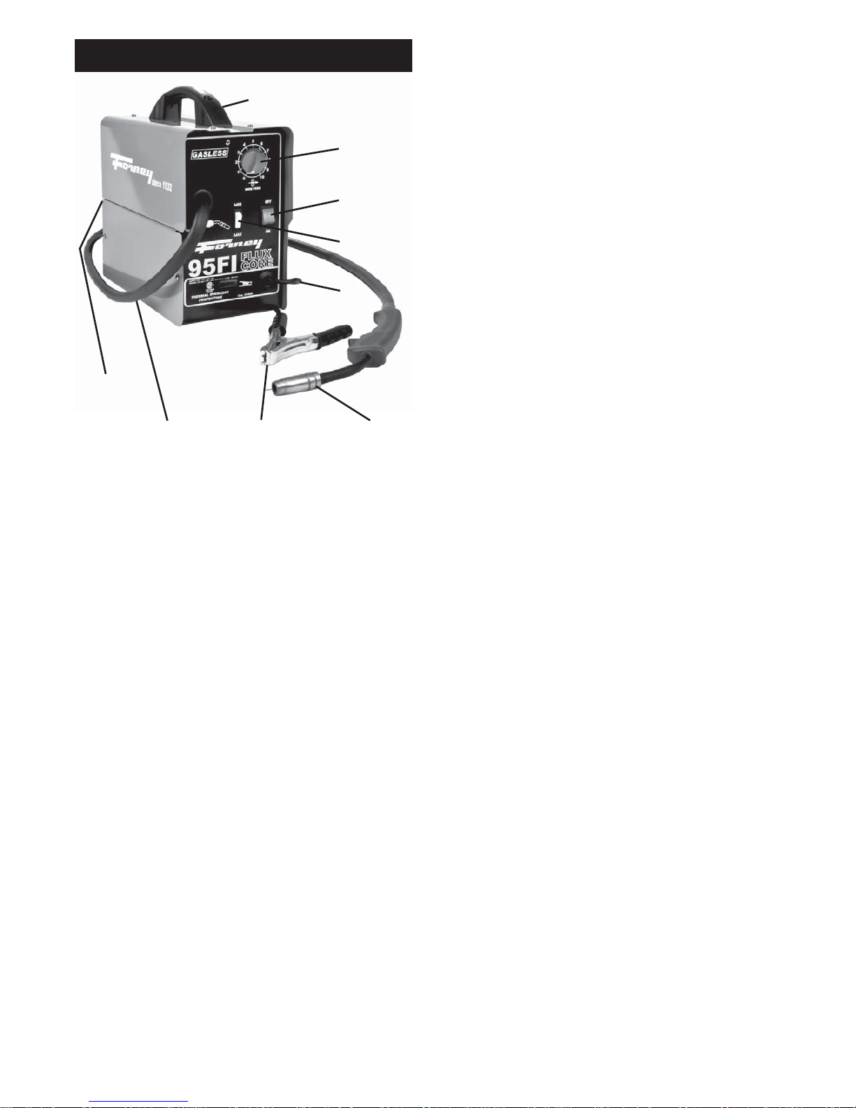
Handle – Rugged, top mounted handle
allows for easy transport of your welder.
Wire Speed Control – Use this dial to adjust
the speed at which the welder feeds wire to
the gun. 1 is the slowest wire feed speed, 10
is the highest. You will need to adjust or
“tune-in” your wire speed for different welding
conditions (thickness of metals, metal type,
wire size, etc.). When the wire speed is properly “tuned-in” the welding wire will melt into
the material you are welding as quickly as it is
fed through the welding gun.
Voltage Selector – This two position switch
adjusts the voltage or “heat” of your welder.
Select MIN setting for lower voltage and
MAX setting for higher voltage. Different
materials and material thickness will require
different voltage settings. You will need to
adjust your voltage accordingly for different
welding conditions. By properly adjusting
your voltage settings and wire feed speed,
you will enable clean, precision welds. (Refer
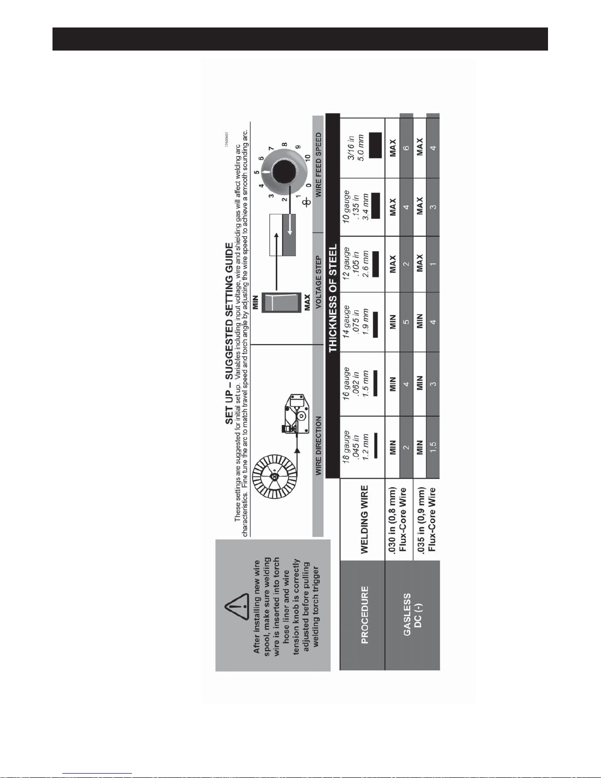
to the Suggested Settings Chart on p.29 of
this manual.)
Power Switch – This switch turns the welder
ON and OFF. (Make sure the power switch is
in the OFF position before performing any
maintenance on the welder.)
Power Cord – This is a standard, grounded
120 volt power cord. (Make sure you are
using a properly grounded 120 Vac, 60Hz,
single phase, 20 amp power source.)
Ground Clamp – Attaching the ground
clamp to your work piece “completes” the
welding current circuit. You must attach the
ground clamp to the metal you are welding. If
the ground clamp is not connected to the
metal work piece you intend to weld, the
welder will not have a completed circuit and
you will be unable to weld. A poor connection
at the ground clamp will waste power and
heat. Scrape away dirt, rust, scale, oil or
paint before attaching the ground clamp.
Ground Cable – The ground cable connects
the ground clamp to the internal workings of
the welder.
Welding Gun and Cable – The welding gun
controls the delivery of the welding wire to
the material to be welded. The welding wire
is fed through the welding cable and welding
gun when the welding gun trigger is pulled.
You will need to install a contact tip and
welding nozzle to the end of the welding gun,
as described later in this manual, prior to
welding.
Welding Terms -Now that you are familiar
with the main parts of the welder, make note
of the following terms. You will see them
used throughout this manual.
weld puddle: The localized volume
of molten metal in a weld prior to its
solidification.
weld angle: The angle of the welding wire,
as it extends from the welding gun, in relation to the item being welded.
slag: The protective coating that forms on
the surface of molten metal.
arc: A sustained luminous discharge of electricity across a gap in a circuit.
welding bead: The extended build up of a
weld, made by pushing or pulling the weld
puddle.
Figure 1. Model Cat. 00304
Welding
Gun
Ground
Clamp
Power
Cable
Ground
Cable
Voltage
Selector
Power
Switch
Wire
Speed
Gun Cable
Handle
Page 11
11
POWER SOURCE CONNECTION
WARNING
High voltage danger from power source!
Consult a qualified electrician for proper
installation of receptacle at the power source.
• This welder must be grounded while in
use to protect the operator from electrical
shock. If you are not sure if your outlet is
properly grounded, have it checked by a
qualified electrician. Do not cut off the
grounding prong or alter the plug in any
way and do not use any adapters
between the welder’s power cord and the
power source receptacle.
Make sure the POWER switch is OFF then
connect your welder’s power cord to a properly
grounded 120 Vac, 60 Hz, single phase, 20
amp power source. Do not operate this welder
if the source voltage is less than 105 Vac or
greater than 132 Vac. Contact a qualified electrician if this problem exists. Improper performance and/or damage to the welder will result if
operated on inadequate or excessive power.
EXTENSION CORDS
For optimum welder performance, an extension
cord should not be used unless absolutely necessary. If necessary, care must be taken in
selecting an extension cord appropriate for use
with your specific welder.
Select a properly grounded extension cord
that will mate directly with the ac power
source receptacle and the welder power cord
without the use of adapters. Make certain
that the extension cord is properly wired and
in good electrical condition.Extension cords
must fit the following wire size guidelines:
• 0-25 ft. requires #12 gauge
• Do not use an extension cord over
25 ft. in length.
ASSEMBLING THE WELDER
The following procedures describe the process
required to assemble, install, maintain, and prepare to weld with your new wire feed welder.
UNPACKING THE WELDER
1. Remove any cartons or bags containing
parts/accessories. (Most parts are
shipped inside the welder door.)
2. Open the cartons or bags packed with
your welder and inspect their contents for
damage.
3. Layout the parts and compare them to
the the packing list in Table 3 to familiarize yourself with the parts and what they
are called. This will help you when reading the manual.
PACKING LIST
Table 3 contains a list of the items you will
find packed in the carton.
Table 3. Packing List
ITEM QTY.
Welder 1
Face Shield 1
Face Shield Handle 1
Face Shield Handle Cover 1
Face Shield Retaining Clips 2
Shaded Lens 1
Welder Handle 1
Handle Screws 2
Handle Caps 2
Wire Brush/Hammer 1
Parts Bag 1
Spool Holder Locking Pin 1
Contact Tip .040 1
Wire .035 Fluxcore 1/2 lb.
Manual, Instruction 1
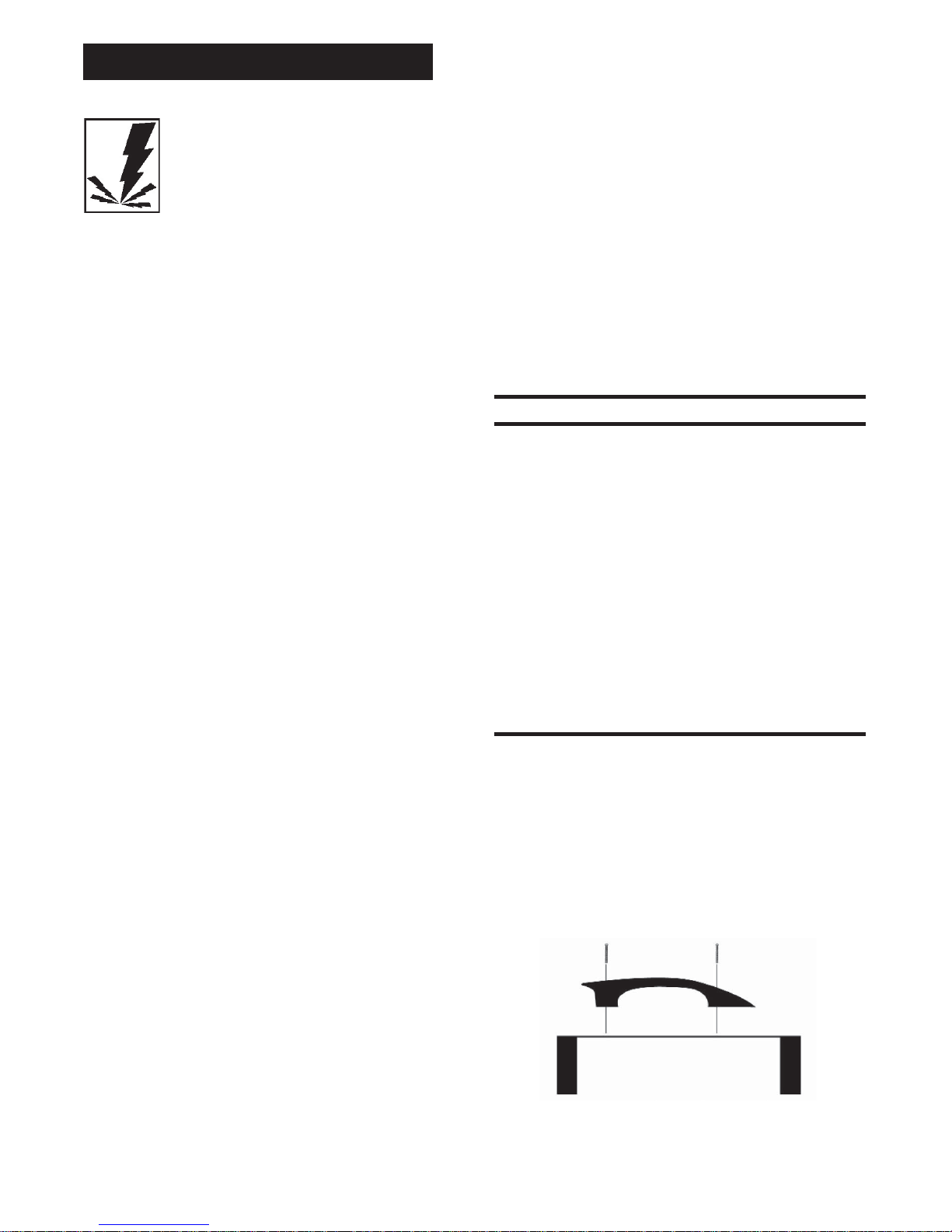
INSTALLING THE HANDLE
1. Insert the tabs of the welder handle into
the slots provided on the top of the welder.
2. Insert a large flat head screw (included in
the accessories bag) into each hole on
the top of the welder handle.
3. With a flat tip screwdriver, securely tighten both screws. (see Figure 3)
WELDER INSTALLATION
Figure 3. Handle Installation
Page 12
12
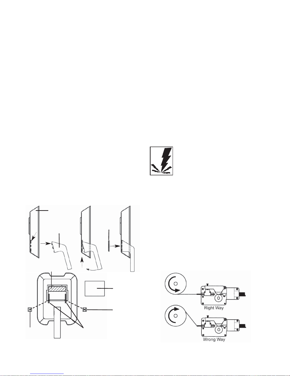
ASSEMBLE THE FACE SHIELD
1. Insert the upper tongue of the handle into
the upper slot on the face shield.
2. Align the second tab on the handle with the
second slot in the face shield by pushing the
bottom of the handle in towards the face
mask, while at the same time pushing
upwards. (Alignment of the second tab is
made easier by applying pressure to the
point shown below.)
3. Once the handle tabs are properly seated in
the face shield slots, install the handle cover
by firmly pushing it into the recessed area on
the face shield.
4. Install the dark glass by sliding it into place
behind the glass retaining tabs.
Note: if your face shield was supplied with a 3” x
3.8” dark glass you may choose to remove the
extra material from the face shield to allow a
larger field of vision when welding. To remove
the extra material, remove the glass from the
face shield and carefully cut the material out of
the face shield with a utility knife.
5. Once protective dark glass has been
installed into face shield, secure it in place
with the retaining clips. Align the holes on
each of the retaining clips with the pins on
the retaining tabs and firmly press into place.
SELECTING THE WELDING WIRE
This welder uses only four inch spools of 0.030
inch (0.8mm) or 0.035 inch (0.9mm) self shielding flux-core wire. Steel from 18 gauge up to
3/16 inch thick can be welded with this wire.
NOTE:
• Metal thinner than 18 gauge cannot be
welded with this machine. Attempting to do
so will cause burn through (blowing holes)
in the metal you are intending to weld.
• If a spool has developed heavy oxidation,
the only solution to the problem is to discard the spool of wire.
If you have an oxidized spool of wire, do not
discard it until you have unspooled a few
turns of wire to see if the wire further down
on the spool is in usable condition, if not, –
discard the spool.
INSTALLING THE WELDING WIRE
WARNING
Electric shock can kill! Always turn the
POWER switch OFF and unplug the welder’s
power cord from the ac power source before
installing wire.
1. Remove the nozzle and contact tip from
the end of the gun assembly.
2. Remove the spindle cap from spindle.
3. Unwrap the spool of wire and then find
the leading end of the wire (it goes
through a hole in the outer edge of the
spool and is bent over the spool edge to
prevent the wire from unspooling) BUT
DO NOT UNHOOK IT YET.
4. Place the spool on the spindle in such a
Figure 2. Face Shield Assembly
Figure 4. Wire Installation
Face Shield
Handle
Handle
Cover
Retaining
Tabs
Retaining
Clip
Retaining
Clip
Dark
Glass
Extra
Material
Page 13

13
manner that when the wire comes off the
spool, it will look like the top illustration in
Figure 4.
5. Insert the spool retaining tab into the
spool shaft. The tab will lock into place,
prohibiting the spool from coming loose
during operation.
6. Use a wire cutter, cut the bent end off the
leading end of the wire so that only a
straight leading end remains.
7. Hold the tension arm up off the drive
roller and insert the leading end of the
wire into the inlet guide tube. Then push
it across the drive roller and into the gun
assembly about six inches.
8. Line the wire up in the outside groove of
the drive roller, then allow the drive tension
arm to drop onto the drive roller.
9. Tighten (turn clockwise) the tension
adjusting screw until the tension roller is
applying enough force on the wire to prevent it from slipping out of the drive
assembly.
9. Let go of the wire.
10. Plug the welder’s power cord into the ac
power source. Adjust the HEAT selection
switch, on the front of the welder, to either
of the two heat settings.
WARNING
ARC RAYS CAN INJURE EYES!
To reduce the risk of arc flash, make certain
that the welding wire, when it finally comes
out of the end of the gun, does not touch the
ground clamp or any grounded piece of
metal. IMPORTANT! The welding wire is car-
rying welding current whenever the welder is
turned on.
11. Pull the trigger on the welding gun to feed
the wire through the gun assembly.
12. When at least an inch of wire sticks out
past the end of the gun, release the trigger.
13. Install the supplied 0.040 inch (1.0mm)
size contact tip.
Note: Due to inherent variances in fluxcored welding wire, it may be necessary
to use a welding tip one size larger than
your flux-core wire if jams occur.
14. Slide the contact tip over the wire (protruding from the end of the gun). Screw
the contact tip into the end of the gun
and hand tighten securely.
15. Install the nozzle on the gun
assembly.
16. Cut off the excess wire that extends past
the end of the nozzle.
WARNING
ARC RAYS CAN INJURE EYES!
To reduce the risk of arc flash, make certain
that the wire coming out of the end of the
gun does not come in contact with the
ground clamp or any grounded material during the drive tension setting process.
17. Set the wire drive tension.
a. Pull the trigger on the gun.
b. Turn the drive tension adjustment
knob clockwise, increasing the drive
tension until the wire seems to feed
smoothly without slipping.
Note: If TOO MUCH tension is applied, the
wire will slip on the drive roller or will not be
able to feed at all. If TOO LITTLE tension is
applied, the spool of wire will want to
unspool itself.
When the drive tension is set correctly, there
should be no slippage between the wire and
the drive roller. But if an obstruction occurs
along the wire feed path, the wire should
then slip on the drive roller.
Page 14
14
Operation of this welder consists of selecting
and adjusting operating controls for optimum
voltage (welding heat) and wire speed settings.
CONTROLS AND INDICATORS
WARNING
ELECTRIC SHOCK CAN KILL!
To remove the risk of electric shock, be
aware that the POWER switch, when OFF,
does not remove power from all internal circuitry in the welder.
The POWER SWITCH controls the main
power to the welder and lights up when the
welder is ON. When the switch is OFF, there
is still power to some areas of the welder.
When working inside the welder or when
removing panels on the welder, make sure
the welder is unplugged from the wall outlet.
The VOLTAGE SELECTOR allows you to
select minimum and maximum heat settings.
Refer to the Suggested Settings Chart on
p.29 of this manual for suggestions on which
heat setting to use for your welding job.
PREPARATIONS FOR WELDING
An important factor in making a satisfactory
weld is preparation. This includes studying
the process and equipment and then practice
welding before attempting to weld finished
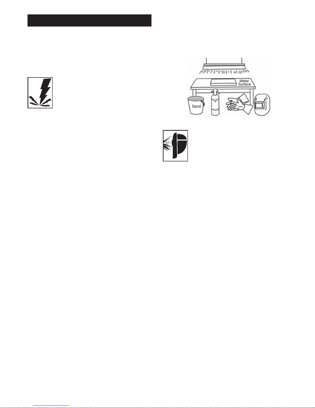
product. An organized, safe, convenient,
comfortable, well-lighted work area should be
available to the operator. The work area
should specifically be free of all flammables
with both a fire extinguisher and bucket of
sand available.
To properly prepare for welding, it is
necessary to:
• Prepare an organized, well lit work area
(see Figure 5).
• Provide protection for the eyes and skin
of the operator and bystanders.
• Set up the work piece and make the
ground clamp connection.
• Select the electrode.
• Adjust the heat control.
WARNING
Exposure to a welding arc is extremely
harmful to the eyes and skin. Prolonged
exposure to a welding arc can cause blindness and burns. Never strike an arc or begin
welding unless you are adequately protected. Wear flameproof welding gloves, heavy
long sleeved shirt, cuffless trousers, high
topped shoes and a welding helmet.
SETTING UP THE WORK PIECE
Welding Positions
Welding with an ac wire welder can be done
in any of three basic positions: Flat,
Horizontal, and Vertical. Flat welding is generally easier, faster and allows for better penetration. The heat (amperage) selections will
be affected by the positions. Vertical welding
is usually only attempted when using a dc
welder. If possible, the work piece should be
positioned so that the bead will run on a flat
surface.
PREPARING THE JOINT
For effective welding, the surfaces to be
joined must be free of dirt, rust, scale, oil or
paint. Welding on metals not properly
cleaned will cause a brittle and porous weld.
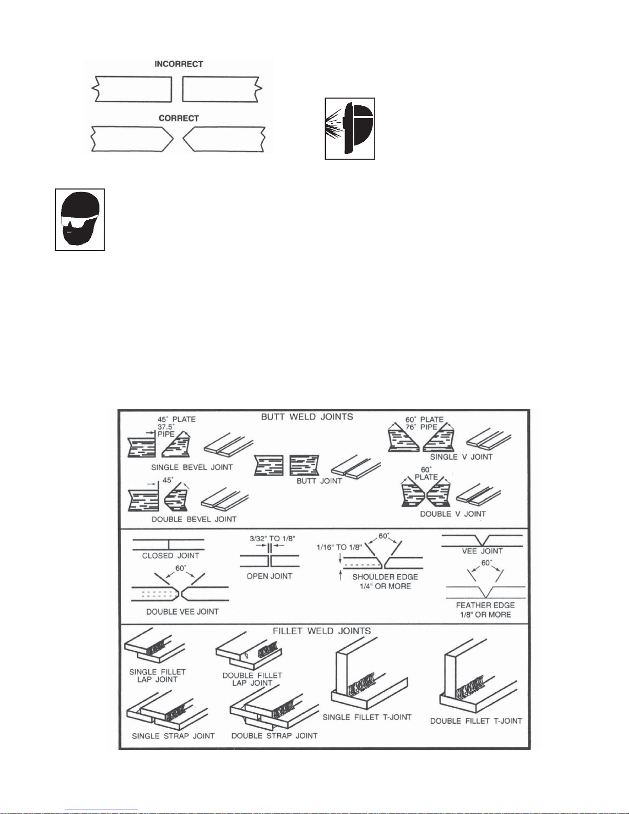
If the base metal pieces to be joined are thick
or heavy, it may be necessary to bevel the
edges, with a metal grinder, at the point of
OPERATION
Figure 5. Work Area
Page 15
15
contact, as in Figure 6. The angle of the bevel
should be approximately 60 degrees.
WARNING
To help prevent eye injuries when
grinding, always wear goggles. The grinder
must also be inspected to verify that it is in
good condition.
See the chart, TYPES OF WELD JOINTS, in
Figure 6, for detailed instructions for preparing the weld joint.
During the welding, the work pieces will
become hot and will tend to expand. The
expansion may cause the pieces to shift from
the regular position. If possible, the work
pieces should be clamped into the position
they are to occupy when the welding is complete.
WARNING
ARC RAYS CAN INJURE EYES AND
BURN SKIN! To reduce the risk of injury
from arc rays, never strike a welding arc until
you, and all bystanders in the welding area,
have welding helmet or shield in place and
are wearing the recommended protective
clothing. DO NOT CONTINUE unless you
have read, understand and intend to follow
the entire SAFETY SUMMARY provided at
the front of this manual.
GROUND CLAMP CONNECTION
The ground clamp connection is part of the
current circuit. A poor connection at the
ground clamp will waste power and heat.
Scrape away dirt, rust, scale, oil or paint.
Make sure the ground clamp touches the
metal of the workpiece.
Figure 6. Edge Preparation
Figure 7. Types of Weld Joints
Page 16
16
LEARNING TO WELD
Flux core wire welding (FCAW) is the
process of uniting metallic parts by heating
and allowing the metals to flow together
through the use of an electrical arc. The
electrical arc is created between a continuous consumable wire electrode (the welding
wire) and the work piece. An atmosphere
created by the burning flux protects the weld
puddle from contamination and enhance the
welding capabilities of the electrical arc.
Whether you have welded before or not, it is
important that you become familiar with your
new welder, its controls, and the results
achieved at different settings. We strongly
recommend that you practice with your new
welder on scrap metal trying different heat
settings, base metal thicknesses, and welding positions for each type and size of wire
you will be using. By doing this you will gain
a feel for how changes in these welding variables affect the weld.
Of course, if you have not welded before,
you will need to develop welding skills and
techniques as well.
The self-taught welder learns through a
process of trial and error. The best way to
teach yourself how to weld is with short periods of practice at regular intervals. All practice welds should be done on scrap metal
that can be discarded. Do not attempt to
make any repairs on valuable equipment
until you have satisfied yourself that your
practice welds are of good appearance and
free of slag or gas inclusions. What you fail
to learn through practice will be learned
through mistakes and re-welds later on.
HOLDING THE GUN
The best way to hold the welding gun is the
way that feels most comfortable to you.
While practicing to use your new welder,
experiment holding the gun in different positions until you find the one that seems to
work best for you.
Position the Gun to the Work Piece
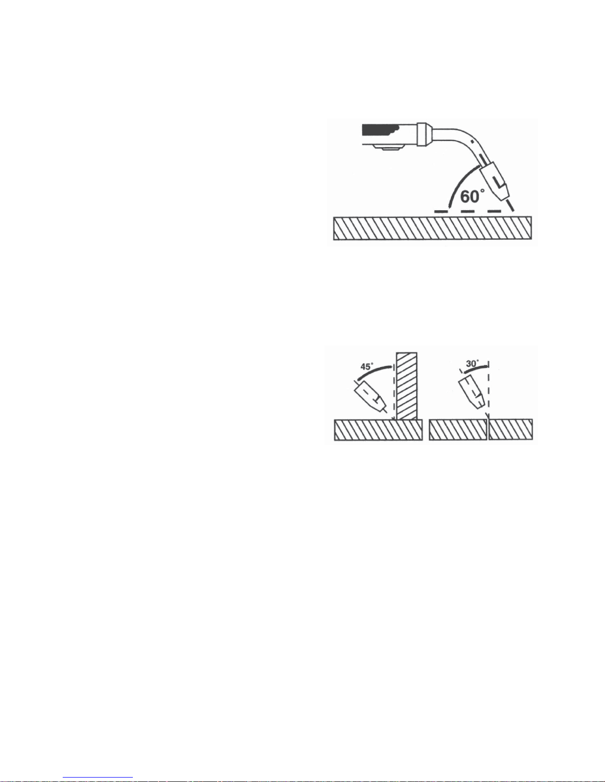
There are two angles of the gun nozzle in
relation to the work piece that must be considered when welding.
1. Angle A (Figure 8) can be varied, but in
most cases the optimum angle will be 60
degrees. The point at which the gun handle is parallel to the work piece. If angle A
is increased, penetration will increase. If
angle A is decreased, penetration will
decrease also.
2. Angle B (Figure 9) can be varied for two
reasons: to improve the ability to see the
arc in relation to the weld puddle and to
direct the force of the arc.
The force of the welding arc follows a
straight line out of the end of the nozzle.
If angle B is changed, so will the direction of
arc force and the point at which penetration
will be concentrated.
On a butt weld joint, the only reason to vary
angle B from perpendicular (straight up) to
the work piece would be to improve visibility
of the weld puddle. In this case, angle B can
be varied anywhere from zero to 45 degrees
with 30 degrees working about the best.
On a fillet weld joint, the nozzle is generally
positioned in such a manner so as to split
the angle between the horizontal and vertical
members of the weld joint. In most cases, a
fillet weld will be 45 degrees.
Angle A
Figure 8. Gun Position, Angle A
Angle B
Figure 9. Gun Position, Angle B
Page 17
17
Distance from the Work Piece
The end of the welding gun is designed with
the contact tip recessed from the end of the
nozzle and the nozzle electrically insulated
from the rest of the gun. This permits the
operator to actually rest the nozzle on the
work piece and drag it along while welding.
This can be very helpful to beginning welders
to steady the gun, allowing the welder to
concentrate on welding technique. If the nozzle is held off the work piece, the distance
between the nozzle and the work piece
should be kept constant and should not
exceed 1/4 inch or the arc may begin sputtering, signaling a loss in welding performance
LAYING A BEAD
WARNING
EXPOSURE TO A WELDING ARC IS
EXTREMELY HARMFUL TO THE EYES
AND SKIN! Prolonged exposure to the weld-
ing arc can cause blindness and burns.
Never strike an arc or begin welding until you
are adequately protected. Wear flameproof
welding gloves, a heavy long sleeved shirt,
cuffless trousers, high topped shoes and a
welding helmet.
WARNING
ELECTRIC SHOCK CAN KILL! To prevent
ELECTRIC SHOCK, do not perform any
welding while standing, kneeling, or lying
directly on the grounded work.
WELDING TECHNIQUES
MOVING THE GUN
Gun travel refers to the movement of the gun
along the weld joint and is broken into two elements: Direction and Speed. A solid weld bead
requires that the welding gun be moved
steadily and at the right speed along the weld
joint. Moving the gun too fast, too slow, or
erratically will prevent proper fusion or create a
lumpy, uneven bead.
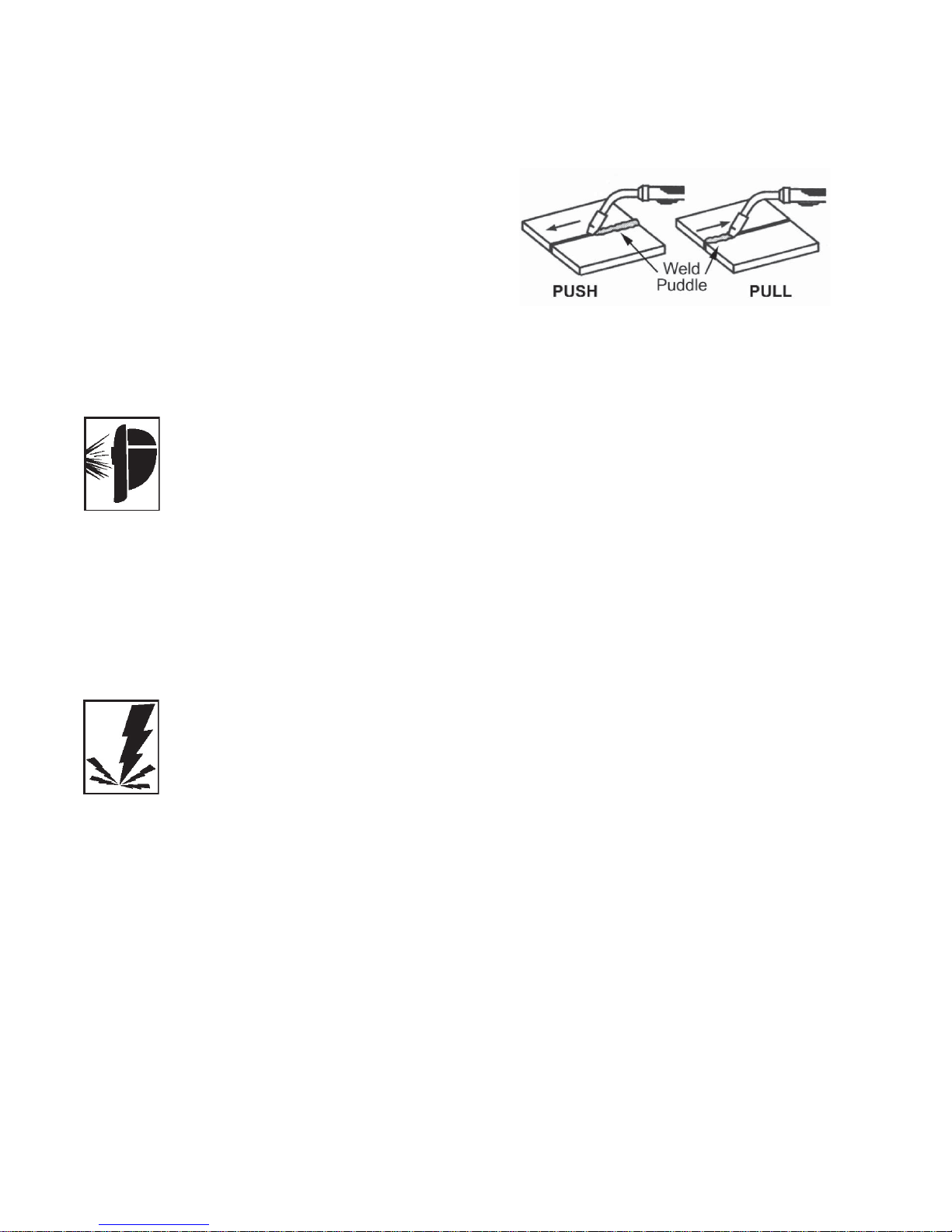
1. TRAVEL DIRECTION is the direction the
gun is moved along the weld joint in relation to the weld puddle. The gun is either
PUSHED (see Figure 10) into the weld
puddle or PULLED away from the weld
puddle.
For most welding jobs you will pull the gun
along the weld joint to take advantage of the
greater weld puddle visibility.
2. TRAVEL SPEED is the rate at which the
gun is being pushed or pulled along the
weld joint. For a fixed heat setting, the
faster the travel speed, the lower the penetration and the lower and narrower the
finished weld bead. Likewise, the slower
the travel speed, the deeper the penetration and the higher and wider the finished
weld bead.
TYPES OF WELD BEADS
The following paragraphs discuss the most
commonly used welding beads.
Once you have the gun in position with the
wire lined up on the weld joint, lower your
helmet, pull the trigger and the arc will start.
In a second or two you will notice a weld
puddle form and the base of the bead beginning to build. It is now time to begin to move
with the gun. If you are just learning to weld,
simply move the gun in a straight line and at
a steady speed along the weld joint. Try to
achieve a weld with the desired penetration
and a bead that is fairly flat and consistent in
width.
You can begin to try some different weld
bead types.
There are two basic types of weld beads, the
stringer bead and the weave bead.
Figure 10. Travel Direction
Page 18
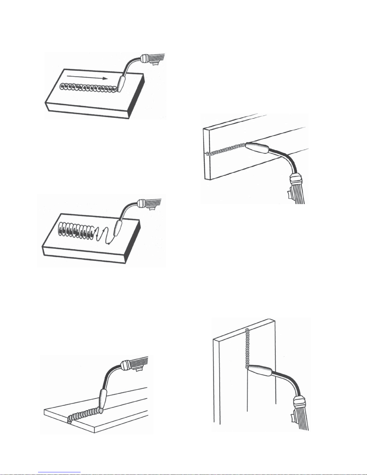
Figure 12. Weave Bead
18
Figure 13. Flat Position
1. The STRINGER BEAD (Figure 11) is
formed by traveling with the gun in a straight
line while keeping the wire and nozzle centered over the weld joint. This is the easiest
type of bead to make.
2. The WEAVE BEAD (Figure 12) is used
when you want to deposit metal over a wider
space than would be possible with a stringer
bead. It is made by weaving from side to
side while moving with the gun. It is best to
hesitate momentarily at each side before
weaving back the other way.
WELDING POSITIONS
There are three basic welding positions: flat,
horizontal, and vertical.
1. The FLAT POSITION (Figure 13) is the
easiest of the welding positions and is probably the one you have been using thus far. It
is best if you can weld in the flat position if at
all possible as good results are easier to
achieve.
2. The HORIZONTAL POSITION (Figure 14)
is next in difficulty level. It is performed very
much the same as the flat weld except that
angle B (see POSITION THE GUN TO THE
WORK PIECE - p16) is such that the wire,
and therefore the arc force, is directed more
toward the metal above the weld joint. This is
to help prevent the weld puddle from running
downward while still allowing slow enough
travel speed to achieve good penetration. A
good starting point for angle B is about 30
degrees DOWN from being perpendicular to
the work piece.
3. The VERTICAL POSITION (Figure 15) is
the next most difficult position. Pulling the gun
from top to bottom may be easier for many
people, but in some instances it can be difficult
to prevent the puddle from running downward.
Pushing the gun from bottom to top may provide better puddle control and allow slower
rates of travel speed to achieve deeper penetration. When vertical welding, angle B (see
POSITION THE GUN TO THE WORK PIECE
- p16) is usually always kept at zero, but angle
A will generally range from 45 to 60 degrees to
provide better puddle control.
Figure 11. Stringer Bead
Figure 15. Vertical Position
Figure 14. Horizontal Position
Page 19
19
MULTIPLE PASS WELDING
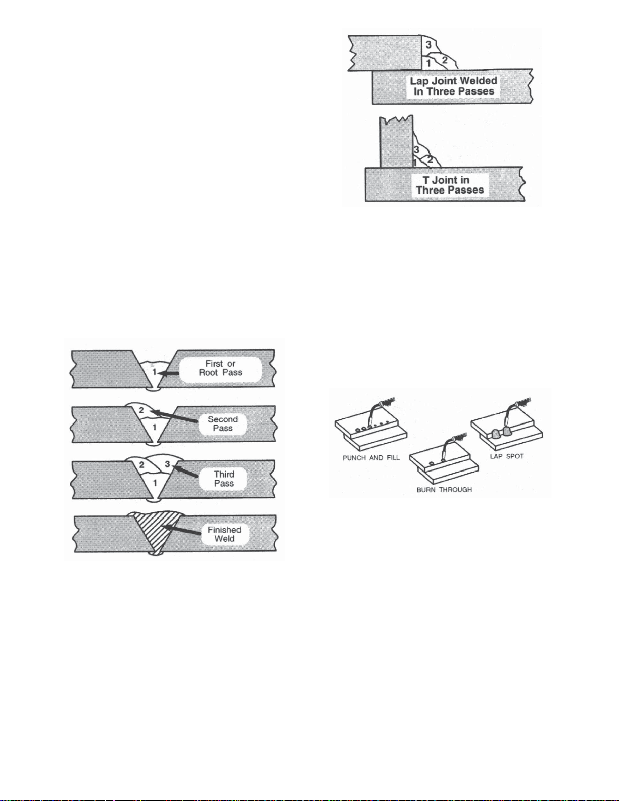
Butt Weld Joints. When butt welding thicker
materials, you will need to prepare the edges
of the material to be joined by grinding a
bevel on the edge of one or both pieces of
the metal being joined. When this is done, a
V is created between the two pieces of
metal, that will have to be welded closed. In
most cases more than one pass or bead will
need to be laid into the joint to close the V.
Laying more than one bead into the same
weld joint is known as a multiple-pass weld.
The illustrations in Figure 16 show the
sequence for laying multiple pass beads into
a single V butt joint.
NOTE: WHEN USING SELF-SHIELDING
FLUX-CORE WIRE it is very important to
thoroughly chip and brush the slag off each
completed weld bead before making another
pass or the next pass will be of poor quality.
Fillet Weld Joints. Most fillet weld joints, on
metals of moderate to heavy thickness, will
require multiple pass welds to produce a
strong joint. The illustrations in Figure 17
show the sequence of laying multiple pass
beads into a T fillet joint and a lap fillet joint.
SPECIAL WELDING METHODS
SPOT WELDING
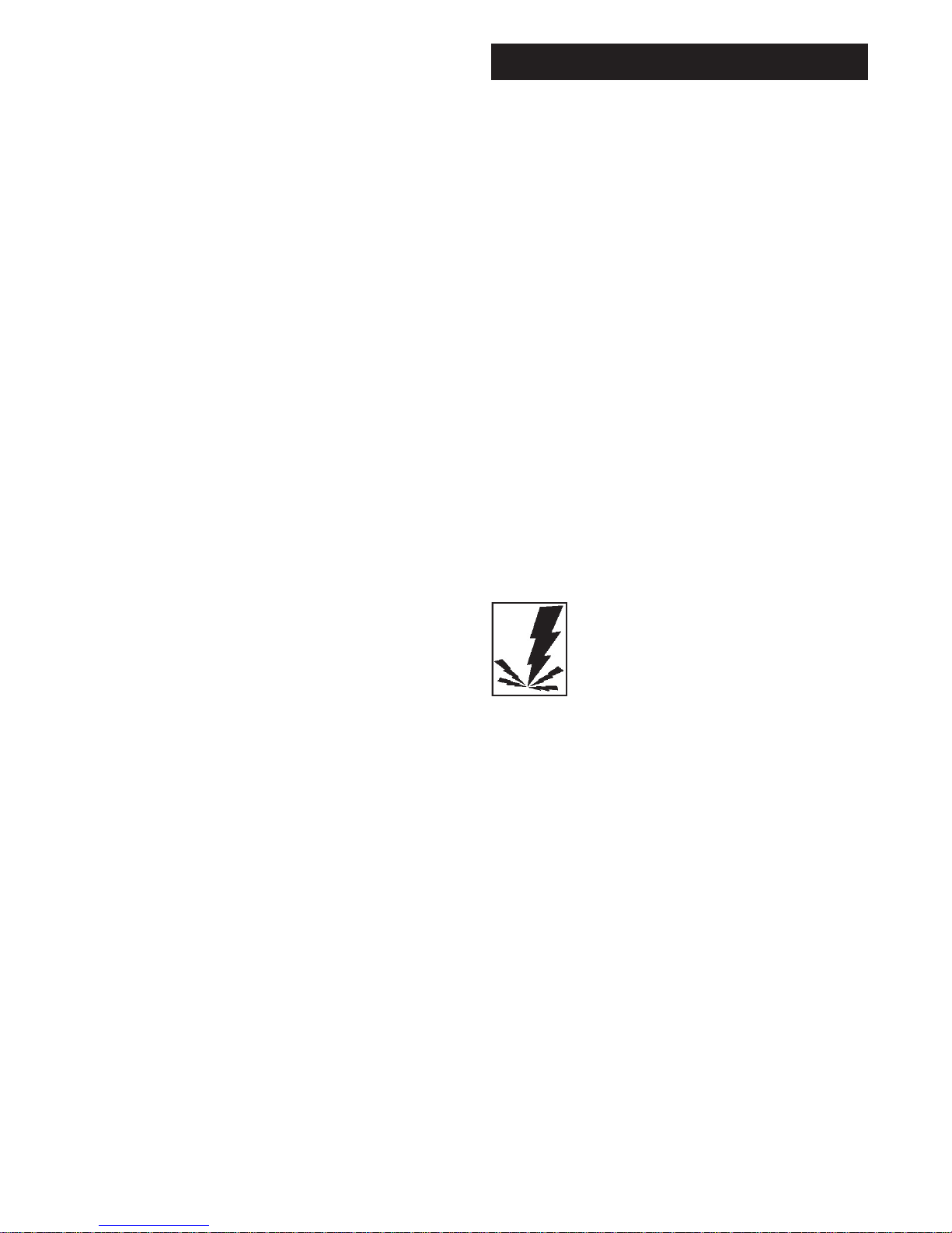
The purpose of a spot weld is to join pieces
of metal together with a spot of weld instead
of a continuous weld bead. There are three
methods of spot welding: Burn-Through,
Punch and Fill, and Lap (see Figure 18).
Each has advantages and disadvantages
depending on the specific application as well
as personal preference.
1. The BURN-THROUGH METHOD welds
two overlapped pieces of metal together
by burning through the top piece and into
the bottom piece.
With the burn-through method, larger wire
diameters tend to work better than smaller
diameters because they have greater current carrying capabilities allowing the arc
to burn through very quickly while leaving
a minimal amount of filler metal build up.
Figure 16. Butt Joints
Figure 17. Fillet Weld Joints
Figure 18. Spot Welding
Page 20
20
Do not use 0.030 inch self-shielding flux-core
wires when using the burn-through method
unless the metal is VERY thin or excessive
filler metal build-up and minimal penetration
is acceptable.
Always select the HIGH heat setting with the
burn-through method and tune-in the wire
speed prior to making a spot weld.
2. The PUNCH AND FILL METHOD produces a weld with the most finished
appearance of the three spot weld methods. In this method, a hole is punched or
drilled into the top piece of metal and the
arc is directed through this hole to penetrate into the bottom piece. The puddle is
allowed to fill up the hole leaving a spot
weld that is smooth and flush with the surface of the top piece.
Select the wire diameter, heat setting, and
tune-in the wire speed as if you were
welding the same thickness material with
a continuous bead.
3. The LAP SPOT METHOD directs the
welding arc to penetrate the bottom and
top pieces, at the same time, right along
each side of the lap joint seam.
Select the wire diameter, heat setting, and
tune-in the wire speed as if you were
welding the same thickness material with
a continuous bead.
SPOT WELDING INSTRUCTIONS
1. Select the wire diameter and heat setting
recommended above for the method of
spot welding you intend to use.
2. Tune in the wire speed as if you were
going to make a continuous weld.
3. Hold the nozzle piece completely perpendicular to and about 1/4 inch off the work
piece.
4. Pull the trigger on the gun and release it
when it appears that the desired penetration has been achieved.
5. Make practice spot welds on scrap metal,
varying the length of time you hold the
trigger, until a desired spot weld is made.
6. Make spot welds on the actual work piece
at desired locations.
GENERAL MAINTENANCE
This welder has been engineered to give
many years of trouble-free service providing
that a few very simple steps are taken to
properly maintain it.
1. Keep the wire drive compartment lid
closed at all times unless the wire needs
to be changed or the drive tension needs
adjusting.
2. Keep all consumables (contact tips, nozzles, and gun liner) clean and replace when
necessary. See CONSUMABLE MAINTENANCE and TROUBLESHOOTING later in
this section for detailed information.
3. Replace power cord, ground cable,
ground clamp, or gun assembly when
damaged or worn.
4. Periodically clean dust, dirt, grease, etc.
from your welder. Every six months or as
necessary, remove the side panels from
the welder and air-blow any dust and dirt
that may have accumulated inside the
welder.
WARNING
ELECTRIC SHOCK CAN KILL! To
reduce the risk of electric shock, always
unplug the welder from its ac power source
before removing side panels.
CONSUMABLE MAINTENANCE
IT IS VERY IMPORTANT TO MAINTAIN THE
CONSUMABLES TO AVOID THE NEED
FOR PREMATURE REPLACEMENT OF
THE GUN ASSEMBLY.
MAINTAINING THE CONTACT TIP
The purpose of the CONTACT TIP is to
transfer welding current to the welding wire
while allowing the wire to pass through it
smoothly.
Always use a contact tip stamped with the
same diameter as the wire it will be used with.
Note: Due to inherent variances in flux-cored
welding wire, it may be necessary to use a
contact tip one size larger than your flux core
wire if wire jams occur.
MAINTENANCE
Page 21

21
1. If the wire burns back into the tip, remove
the tip from the gun and clean the hole
running through it with an oxygen-acetylene torch tip cleaner or tip drill.
2. Over time, the hole in the contact tip will
become worn by the wire passing through
it. The more worn this hole becomes, the
less efficient is the transfer of welding current to the wire and eventually arc breakage and difficult arc starting will result.
Replace contact tips when signs of wear
become apparent.
CAUTION
KEEP THE NOZZLE CLEAN!
During the welding process, spatter and slag
will build up inside the nozzle and must be
cleaned out periodically. Failure to clean
and/or replace the nozzle in a timely fashion
WILL CAUSE DAMAGE TO THE FRONTEND OF THE GUN ASSEMBLY, which is
NOT REPLACEABLE. The results of the
inaction will REQUIRE THE REPLACEMENT
OF THE ENTIRE GUN ASSEMBLY.
1. Stop welding and clean any accumulated
slag or spatter from the nozzle every 5 to
10 minutes of welding time.
2. If slag cannot be thoroughly cleaned from
the nozzle, REPLACE THE NOZZLE!
Failure to keep the nozzle adequately
cleaned can result in the following problems:
A SHORTED nozzle results when spatter
buildup bridges the insulation in the nozzle
allowing welding current to flow through it as
well as the contact tip. When shorted, a nozzle will steal welding current from the wire
whenever it contacts the grounded work
piece. This causes erratic welds and reduced
penetration. In addition, a shorted nozzle
overheats the end of the gun which can
DAMAGE the front-end of the gun.
TESTING FOR A SHORTED NOZZLE
Arcing between the nozzle and the work
piece ALWAYS means the nozzle is shorted,
but this can be hard to detect through the
lens of a welding helmet. The following testing method is another way to tell if a nozzle
is shorted.
With the welder unplugged from the ac power
source, touch the probes of an ohmmeter or
continuity tester to the end of the contact tip
and the outside of the nozzle. If there is any
continuity at all, the nozzle IS shorted. Clean
or replace as needed.
REPLACE A GUN LINER
When installing a new gun liner, care must
be taken not to kink or otherwise damage the
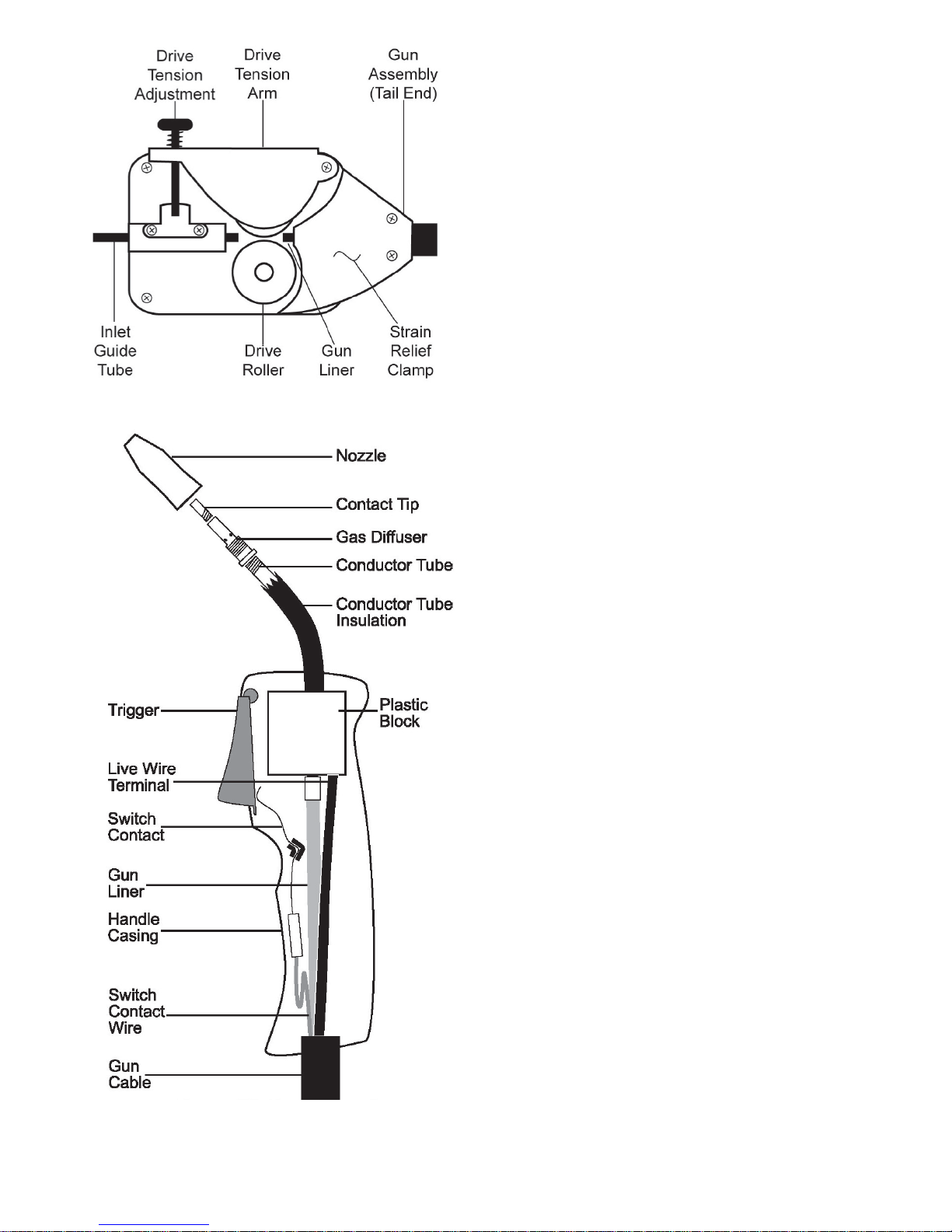
gun liner. See Figure 19 for the drive assembly and Figure 20 for the gun assembly.
1. Turn OFF welder POWER SWITCH and
unplug welder from power supply.
2. Open the welder side panel.
3. Loosen the tension arm and lift it up off
the drive roller.
4. Turn the wire spool counter-clockwise (be
sure to hold onto the wire itself while turning the spool or the wire will unspool itself
when it becomes free of the gun liner),
and remove wire from gun assembly.
5. Lay gun cable and gun handle straight
out in front of unit.
6. Remove the 3 self tapping screws which
secure the gun sleeve to the Feed Motor
Assembly.
7. Take gun handle halves apart by
removing five self tapping screws.
8. Unscrew the gun liner hexagonal nut.
Note: By removing the liner from the gun,
the live wire terminal will also be removed.
9. Remove liner from outer gun sleeve by
pulling it out from the handle end.
10. Install new liner, starting from handle end
and feeding towards unit with fitting end
of liner going towards the block.
11. Return all components to the handle casing and realign them as they were originally. Be sure to also install the live wire
terminal. Note: Be sure to assemble the
new liner and live wire terminal as they
were originally.
12. With both halves of the handle case in
place, tighten the five self tapping
screws.
13. Fit liner for length at feeder end by cutting liner with wire cutters.
14. Reinstall holding clamp at feeder, tightening the 3 self tapping screws.
15. Reinstall the welding wire according to
specifications in INSTALL THE WELDING
WIRE section.
16. Close side panel.
17. Plug welder into power supply and turn
POWER SWITCH to ON position.
Page 22
22
The following paragraphs describe the procedures required to maintain and troubleshoot
your welder.
MAINTAINING THE WELDER
Except for internal and external cleaning,
cleaning the nozzle, and occasionally retightening screws, there is no periodic maintenance recommended for your welder.
TROUBLESHOOTING
The TROUBLESHOOTING information on
the next page is provided as a guide to help
resolve some of the more common problems
that could be encountered.
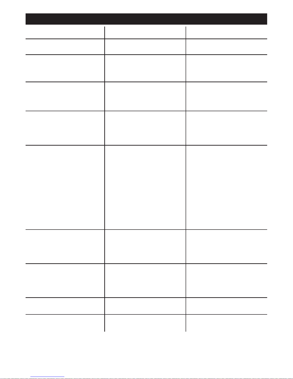
Table 4 is a troubleshooting table provided to
help you determine a possible remedy when
you are having a problem with your welder.
This table does not provide all possible solutions, only those possibilities considered to
likely be common faults. The table consists
of a TROUBLE or symptom, a POSSIBLE
CAUSE for that symptom, and a POSSIBLE
REMEDY for that symptom.
Figure 19. Drive Assembly
Figure 20. Gun Assembly
Page 23
23
TABLE 4 – TROUBLESHOOTING
TROUBLE
Dirty, porous, brittle weld
Wire feed works but no arc
Arc works but no feeding wire
Nothing works
Low output or nonpenetrating weld
Wire is jamming or “birdnesting” at
the drive roller
Wire burns back to contact tip
Ground clamp and/or ground cable
gets hot
Gun nozzle arcs to work surface
POSSIBLE CAUSE
Plugged welding nozzle
1. Bad ground or loose connection
2. Bad connection to gun or faulty
gun
1. Faulty wire speed circuit board
2. No tension on the drive roller
3. Faulty drive motor ( very rare )
1. Faulty trigger on gun
2. Exceeded duty cycle; thermal
protector opened
3. Faulty transformer ( rare )
1. Loose connection inside
machine
2. Too long or improper extension
cord
3. Wrong type or size wire
4. Poor ground connection
5. Wrong size contact tip
6. Loose gun connection or faulty
gun assembly
1. Too much tension on drive roller
2. Gun liner worn or damaged
3. Contact tip is clogged or damaged
4. Liner stretched or is too long
1. Gun liner is worn or damaged
2. Liner stretched or is too long
3. Wrong size contact tip
4. Contact tip is clogged or damaged
Bad connection from cable to
clamp
Slag building inside nozzle or nozzle is shorter
POSSIBLE REMEDY
Clean or replace nozzle.
1. Check ground and connections.
Tighten as necessary.
2. Check connection to gun or
replace gun
1. Replace wire speed circuit board
2. Adjust the drive tension
3. Replace the drive motor
1. Replace trigger
2. Allow welder to cool at least 10
minutes ( observe and maintain
proper duty cycle )
3. Replace transformer
1. Blow inside of machine out with
compressed air, clean and tighten
all connections
2. See EXTENSION CORDS in this
manual.
3. Use 0.030 inch ( 0.8mm ) or
0.035 inch ( 0.9 mm ) E71T-GS self
shielding flux-core wire
4. Reposition clamp and check
cable to clamp connection
5. Use 0.030 inch ( 0.8 mm ) or
0.035 inch ( 0.9 mm ) contact tip
6. Tighten gun or replace gun.
1. Adjust the drive tension. ( See
INSTALLING THE WELDING WIRE )
2. Replace gun liner
3. Replace contact tip
4. Trim liner to proper length
1. Replace gun liner
2. Trim liner to proper length
3. Use correct size contact tip
4. Replace contact tip
Tighten connection or replace cable
Clean or replace nozzle as needed
Page 24
24
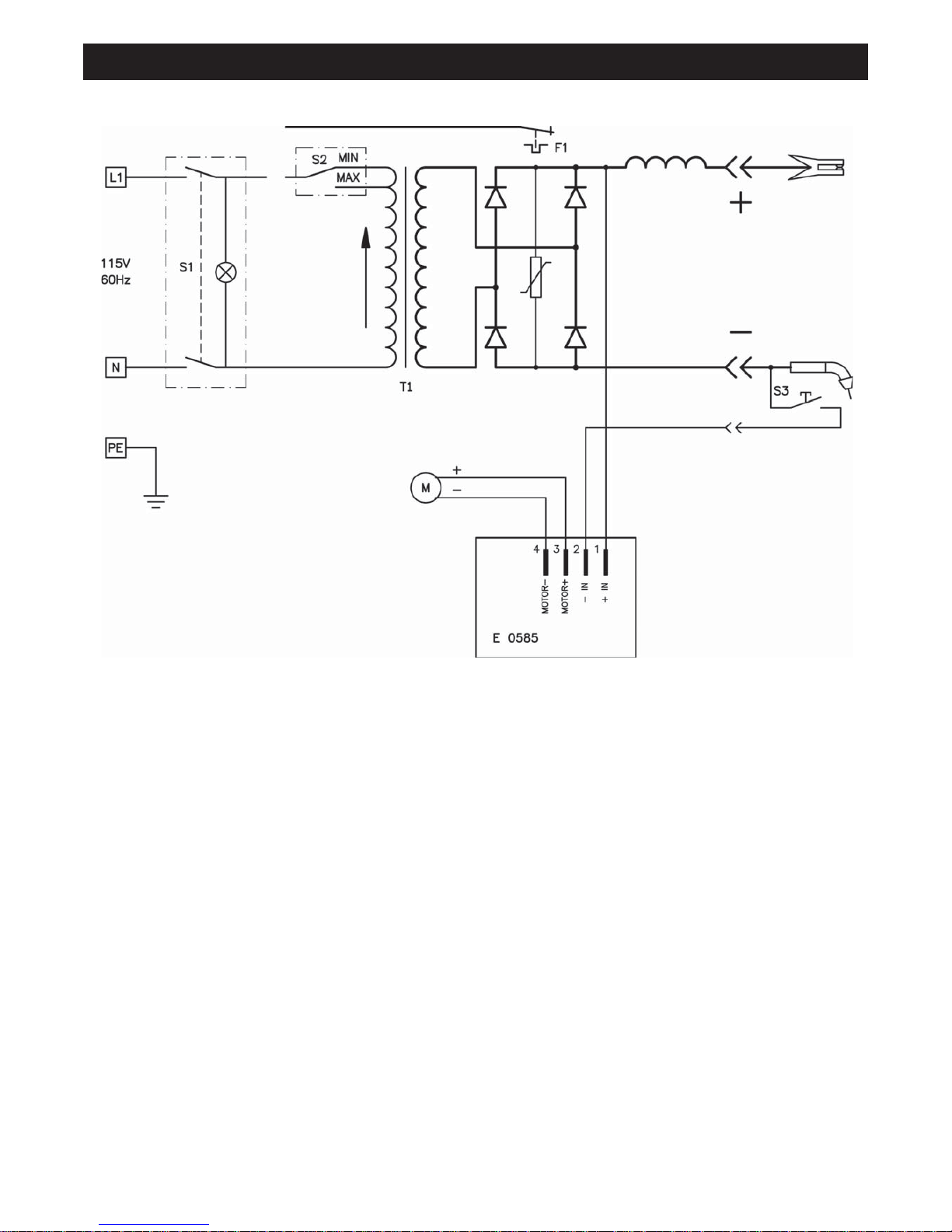
WIRE FEED WELDER WIRING DIAGRAM
Page 25

25
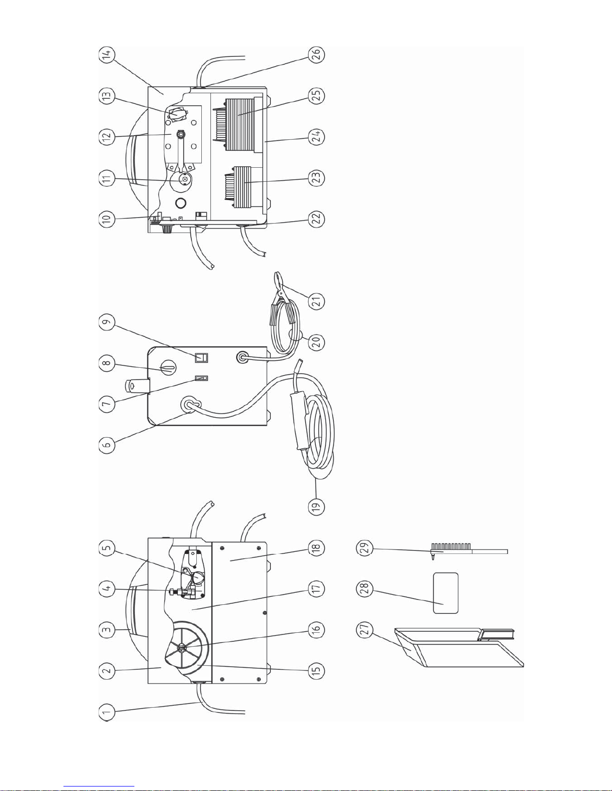
WIRE FEED WELDER PARTS LIST
01 20220018 POWER CABLE 3X14 AWG 2.5M+5-15P PLUG 1
02 05000174 SIDE PANEL W/SCREEN PRINTING+LABEL 1
03 21600036 HANDLE 1
04 44400018 PLASTIC WIRE FEEDER ø28 1
05 33805074 WIRE FEED ROLL ø.7X25 1
06 21690458 TORCH GROMMET (D.40 OPEN ) 1
07 22200038 HIGH/LOW POWER SWITCH 16A 250V 1
08 04600323 KNOB FOR POTENTIOMETER ø38, WIRE SPEED 1
09 22200039 GREEN PILOT LIGHT SWITCH 16A-250V ON/OFF 1
10 22710001 P.C. BOARD E0585.1 220V 1
11 04600144 MOTOR ø28 +PINION 1
12 22400083 RECTIFIER PMS 30B F/1 TYPE 1
13 04600113 COMPLETE THERMOSTAT 100° + SUPPORT 1
14 05000173 RIGHT SIDE PANELW/SCREEN PRINTING+LABEL 1
15 21910046 FLUX CORED WIRE SPOOL 0.035 1/2LB 1
16 04600108 SPOOL HOLDER 1
17 05000175 DIVIDING PANEL +LABEL 1
18 33705325 5015 LEFT SIDE PANEL 1
19 23000094 TORCH AND CABLE ASSY. COMPLETE 2MM² 2M 1
20 43210021 EARTH CABLE 10MM² M1.6 C.120/CONN 1
21 22110005 EARTH CLAMP 120A 1
22 04600233 CABLE CLAMP + SCREW 1
23 44135097 CHOKE 40X25 AL 1
24 05000172 FRONT,BOTTOM,REAR PANEL 1
25 44120131 TRANSFORMER 60HZ 110V 40X60AL 1
26 04600234 CABLE CLAMP ø10 + SCREW 1
27 21905041 PLASTIC MASK 50X105 1
28 21905007 DARK GLASS 75X98 1
29 21905039 HAMMER - BRUSH 1
Page 26
26
Page 27

27
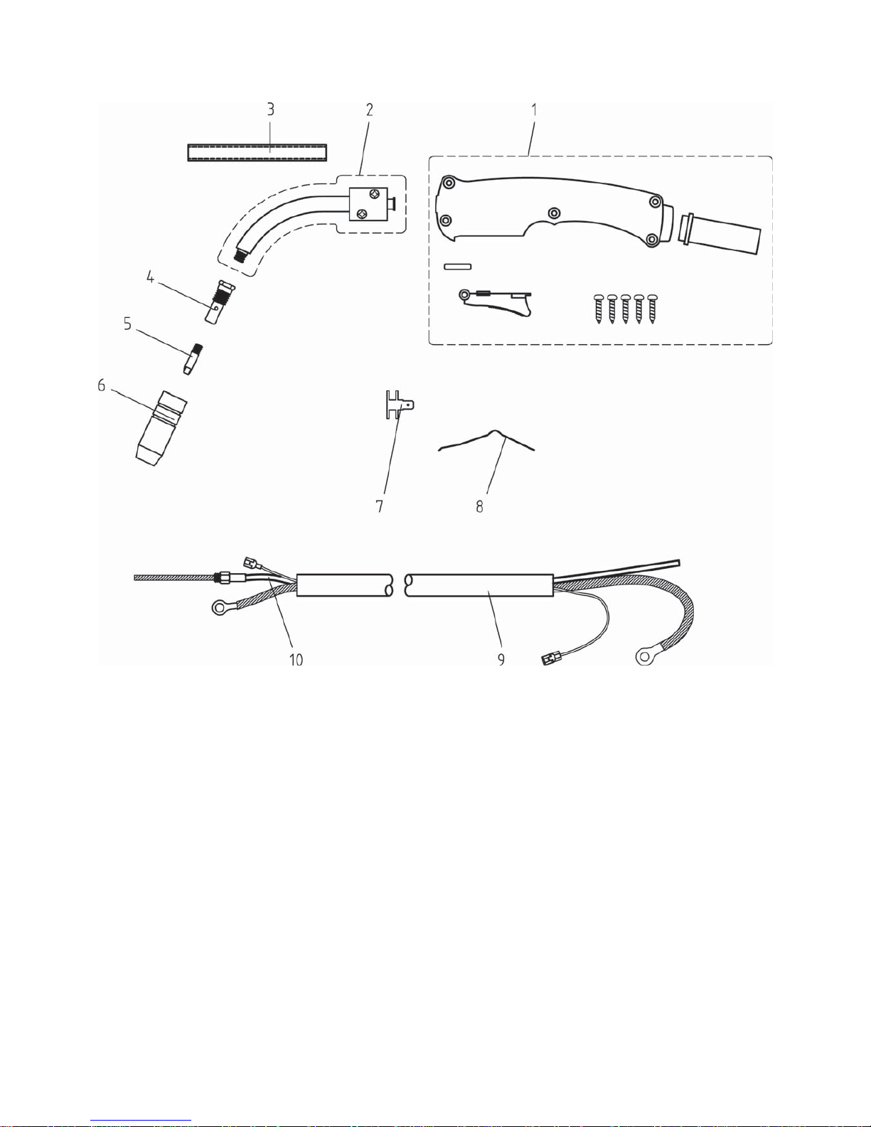
WIRE FEED WELDER GUN PARTS LIST
01 04600163 HANDLE ASSY. BLUE 1
02 23005342 SWAN NECK AND PLASTIC TORCH BODY 1
03 23005285 ISOLATING COVER FOR NECK 1
04 23005316 CONTACT TIP HOLDER 1
05 23005020 0.040 CONTACT TIP 1
06 23005147 TORCH GAS NOZZLE 1
07 21200010 FAST-ON CONTACT 6,3X0,8 1
08 33800032 TORCH CONTACT SPRING 1
09 30900019 RUBBER SLEEVE ø17,5+HOSE 1.7M 1
10 23005354 WIRE LINER 1.4X4.0 WITH CONNECTOR, 2.1 M 1
11 23005322 PLASTIC BLOCK + NECK + DIFFUSER 1
Page 28
28
Page 29
29
SUGGESTED SETTINGS
Page 30

30
NOTES
Page 31

Page 32

 Loading...