

Page 1
COMPANY SPECIALIZING IN BUILT-IN OVENS
AND HOBS
HOBS
PGA 45
FIERO
FIERO BL
FIERO WH
GAS HOB
EN
User’s Manual
Page 2

HOBS
Installation and operation instructions Installation and operation instructions
Dear Customer!
Thank you for purchasing a “FORNELLI” product. We hope, this appliance will meet your
expectations and be a reliable assistant of yours in your kitchen. For correct and safe operation
of the appliance, please carefully read all the chapters in the present manual. Keep your manual for the entire service life of the product you have purchased.
Reading the first part of the manual, you will learn some important conditions of safe operation
of the appliance. To keep your appliance in good condition for a long time, we oer you a lot
of helpful advices and hints on the product care and cleaning. In the manual you can also find
some hints on energy saving.
On the last pages of the manual you can find recommendations which will help you eliminate
minor failures, if any, during use of your appliance.
Your new appliance is made of high-quality materials and fully conforms to any standard of the
European Economic Community.
The manufacturer reserves the right to make changes to the product design to improve its performance. Our household appliances are subject to continual improvement, the performance
is enhanced, and their design is updated. Therefore, drawings and symbols in the manual may
dier from those used for a model you have purchased.
Enjoy your meal!
The manufacturer reserves the right to make changes to the product design in order
to improve its performance.
The appliance has been manufactured in line with European standards and is CE, TUV,
ISO 9001 and EAC certified
The manufacturing date is in the serial number of the product. The serial number is on the internal label.
Serial number explanation: SPG/201408C/0001-50
SPG / 201408C / 0001 - 50
code year month
manufacturing
This example: the appliance was manufactured in August 2014.
order number
in the batc h
number of this
specification
in the batch
Page 3

HOBS
CONTENTS
SAFETY STATEMENTS AND HINTS
Prior to connecting a new appliance ...............................................2
Safety statements .................................................................2
Disposal recommendations ........................................................5
Scope of supply ..................................................................5
Technical data of gas hob .........................................................6
YOUR NEW GAS HOB
Gas hob control ..................................................................8
Electrically-ignited gas burners ....................................................8
Choosing a gas burner for food preparation .......................................10
Use of dishware support grids ....................................................10
INSTALLATION OF GAS HOB
Installation areas ................................................................. 11
Attaching the hob to the tabletop .................................................12
Connection to a gas supply system ...............................................13
Connection to the mains .........................................................14
Setting to various types of gases .................................................15
Adjustment of air supply to gas burners ...........................................15
Minimum flame adjustment ......................................................15
CLEANING AND CARE
Enameled parts .................................................................16
Hobs made of stainless steel .....................................................16
Dishware support grids ..........................................................16
Gas burners .....................................................................16
PERIODIC MAINTENANCE AND REPAIRS
Troubleshooting .................................................................18
1
Page 4

Installation and operation instructions
SAFETY STATEMENTS AND HINTS
HOBS
Attention!
To avoid breakdown of the appliance, keep
in unpacked at a room temperature within 2
hours at least prior to switching on in cold
months.
PRIOR TO CONNECTING
A NEW APPLIANCE
Upon removal of package, make sure that the
appliance and the power cable are not damaged. If any damages, please contact your
sales agency prior to connection to the mains
and gas supply system.
Please bear in mind that making any changes,
or trying to make changes to the technical
data of the present appliance is risk bearing.
Do not disassemble the hob; do not touch any
parts inside it.
Whenever necessary, feel free to contact the
Technical Support.
Prior to connection, make sure that your gas
hob is designed for operation with the type of
gas (G20: main pipeline gas; G30/G31: liquefied gas) being supplied to the appliance. If
the present requirements are not met, for
safety reasons and in order to ensure compliance with local oicial regulations, contact
an oicial authorized expert who will install
the hob and redesign it for another type of
gas.
Information on the type of gas your hob is designed for can be found on the rear side of its
built-in part, close to the gas supply connection point.
Using the gas hob for food preparation might lead to a higher temperature and moisture
content in the premises, where it is installed.
This makes it important to install the hob,
where required ventilation can be provided.
Intensive or prolonged use of the appliance
may require some extra airing or a more
eective ventilation system (for instance, you
may have to open the windows or increase
the kitchen hood ventilation rate).
It is not advisable to install the hob in a strong
draught, because it can blow out gas burner
flames.
SAFETY STATEMENTS
The user shall become informed of safe handling regulations with regard to gas- and electrically-operated household appliances.
These are only qualified professionals who
are permitted to mount and connect the appliance to the mains and gas supply system,
in compliance with the instructions and a
connection diagram. The appliance shall be
connected to a reliable grounding system to
conform to the valid norms of electrical safety.
Prior to any intervention, please make sure
that the appliance is DISCONNECTED from
the mains.
The manufacturer disclaims all liabilities for
damage to humans and property, if the appliance is not or improperly connected to a
grounding system.
These are only adults who are allowed to use
the hob. Take care to ensure that children do
not touch the control console and do not play
with the appliance.
External elements of the appliance have open
flames and heat up to high temperatures.
They remain hot even for some period of time
upon switching o. Do not allow children to
come close to the appliance until it completely cools down.
When using a socket which is in close vicinity
2
Page 5

HOBS
to the appliance, make sure that power cables of electrical appliances being used do not
touch those areas on the hob that may become heated and are laid far enough from hot
surfaces of the appliance. The power cables
shall be attached to the kitchen table and not
touch hot parts of the hob.
At regular intervals (but twice a year at least)
check the technical condition of the power
supply cable and flexible gas supply hose (if
this hose is used for gas supplies). Should
you happen to find any defects (cracks, melting or hardening of materials), contact your
service center immediately. To avoid hazards
of any kind, let your service provider replace
the cable, or a professional of similar qualification.
This gas hob is only designed for food preparation. It shall never be used for heating premises or drying laundry above it.
When overheated, fats and sunflower oil
become inflammable. Preparing your food
with use of fats or sunflower oil (for instance,
frying potatoes in frying oil), do not leave the
appliance unattended.
KEEP IN MIND!
Never use water to extinguish inflamed
fats or sunflower oil! Tightly cap the dishware with inflamed oil or fat, or cover
it with a material which would prevent
access of oxygen to flames.
Keep the appliance clean. Food residues may
cause fire.
Upon each use make sure that the position
of any switch on the control console of hob
(and, as may be required, on that of the gas
supply) is OFF or CLOSED.
In the event of breakdown disconnect the
hob from the mains and gas supply system.
Do not operate the faulty appliance for it
may be dangerous. Do not try to repair the
equipment yourself. Repairs performed by
non-qualified persons may result in damage
to the appliance and injuries. The first thing
to do is to refer to the user’s manual.
Should you fail to have found information
required, feel free to contact the nearest
service center. The appliance may only be
repaired by experts of an authorized service
center.
Demand the use of branded spare parts only!
When connecting the hob to a liquefied gas
supply system, arrange and operate gas bottles in line with the Fire Safety Regulations
(in Russia they are named “PPB 01-03 P.111”).
ATTENTION!
IT IS EXPRESSLY PROHIBITED TO CARRY OUT A LEAKAGE TEST USING MATCHES OR OPEN FLAMES!
ATTENTION!
Upon occurrence of gas odor, turn o the
gas delivery cock (shut o the gas bottle
valve). Upon that, turn o any cock at the
hob. Open the windows, do not take any
action which may result in occurrence of
sparks or fire before gas escape is completely eliminated: do not strike matches,
do not smoke, do not switch on / o the
lighting and electrical appliances.
If you are unable to detect and eliminate gas escape, immediately call the gas
emergency service.
3
Page 6
Installation and operation instructions
HOBS
RECOMMENDATIONS
ON DISPOSAL
Any material used for manufacture of the gas
hob is environmentally sound and recyclable.
Observe the Environment Protection Rules,
use appropriate methods of separate waste
collection.
Used appliances or those which have become unfit for further use are considered as
useless waste. Various materials used for
manufacture of your appliance may be subject to disposal.
You may become informed of disposal options, contacting your sales agency or local
authority.
Prior to disposing the appliance for scrap,
please bear in mind that in children’s hands
its further use may result in an accident.
Take care to make it as safe as possible. Cut
the power cable o and make the appliance
completely inoperable.
Make sure to carefully follow the instructions
in the present manual.
SCOPE OF SUPPLY
Your gas hob is classified as a built-in appliance.
The manufacturer’s plate to indicate the
model of the hob is on the rear panel of its
built-in part, where another plate is located
to indicate the type of gas your appliance is
designed for (G20, G30/G31).
The scope of supply includes as follows:
1 Gas hob – 1 piece;
2 Connecting piece to be used for various
gas supply sources – 1 piece;
3 Additional bottled gas nozzles – 3 pieces;
4 Clamp to be attached to a piece of kitchen
furniture, including a set of screws –
4 pieces;
5 Sealing gasket – 1 piece;
6 Cast-iron grill – 3 pieces;
7 User’s manual.
STORAGE
Keep the appliance in a dry place, away from
sources of high temperatures and sunlight. During storage, avoid rapid temperature
changes. Storage of an unpackaged product
is not permitted.
TRANSPORTATION
During the transport of the package, it must
be avoided from falling or other mechanical
influences.
4
Page 7

HOBS
TECHNICAL DATA
The present equipment meets the EEC standards as follows:
• 90/396/EEC — gas-fired equipment;
• 73/23/EEC — low voltage equipment;
• 89/336/EEC — EMC;
• 93/68/EEC — general standards;
• 89/109/EEC — food contact materials or subjects.
Electrical ignition system supply voltage: 220–240 V~, 50–60 Hz
Protection Rating: 1.
Net weight, kg: 10,2.
Dimensions of the Hob and the Opening for Building-in of the Hob
Dimensions, mm Height Width
(length)
Visible part 8 450 510
Built-in part 58 426 485
Niche 35–45* 430 490
* With a width of the tabletop less than 35 mm, use an additional space plate (not included).
Power of gas burners: max. 6,55 kW
Parameter Power
Gas burner type max ./min.
kW
Small 1,0/0,35
Middle sized 1,75/0,6 5
WOK 3,8/1,9
Depth
5
Page 8
HOBS
Installation and operation instructions
YOUR NEW GAS HOB
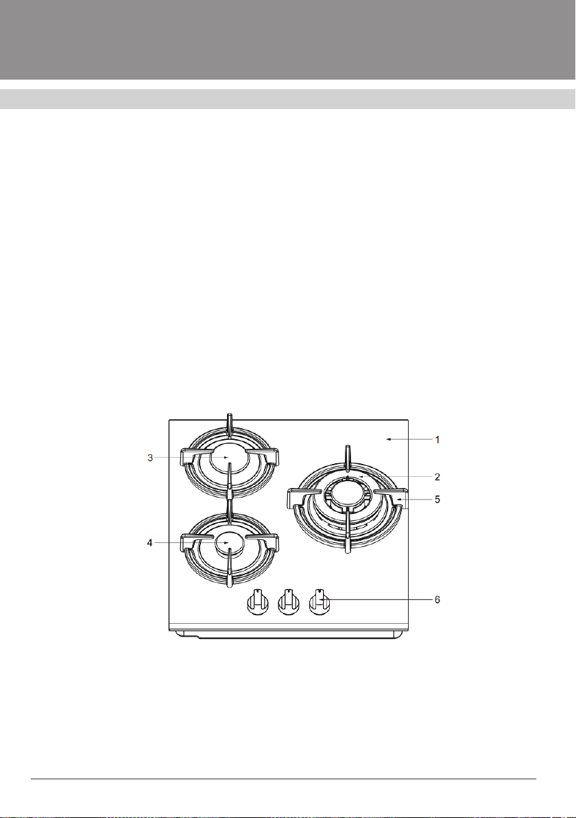
MODEL PGA 45 FIERO
General view of this modification is presented in Figure 1, where the specific components
are designated with position numbers as follows:
1. Gas hob surface
2. WOK gas burner
3. Middle-sized gas burner
4. Small gas burner
5. Dishware support grid
6. Gas burner control knobs .
Fig. 1
6
Page 9

HOBS
GAS HOB CONTROL
Gas flow to burners (gas burner capacity) is
regulated by means of knobs (Figure 2). The
knobs, in turn, are controlled by cocks.
Symbols “Max. flame” , “Min. flame” and
“Flame OFF” are on the hob, close to cont-
rol knobs. Close to the symbol “Max. flame”
there is the “Ignition sparks” symbol which
means that the appliance is equipped with an
automated system of electrical ignition.
Attention! Any operating position of a
control knob shall be selected between
“Max. flame” and “Min. flame” . Between these positions one can smoothly
adjust continuous and stable supply of
gas to gas burners of the hob. In no circumstances select an operating positi-
on between “Max. flame” and “Flame
OFF” .
For a more convenient flame control ignite gas
prior to putting the dishware onto the grid.
Any model described herein is equipped with
electrically-ignited gas burners, but some models have, in addition to that, a gas escape prevention system (alternatively, it is called “gas
control”). Figure 3 presents a general view of a
disassembled gas burner. Its main components
as follows can be highlighted:
Fig. 2
1. Gas burner cap
2. Flame spreader
3. Igniter
4. Thermoelement of “gas control”.
Let us consider specifics of gas ignition in
both cases.
Fig. 3
7
Page 10

Installation and operation instructions
HOBS
ELECTRICALLY-IGNITED
GAS BURNERS
These gas burners do not have Position 4, as
shown in Figure 3.
To ignite a gas burner, press the
selected gas burner control knob,
turn it counterclockwise to the positi-
on of the symbol “Max. flame” that
corresponds to maximum gas supply.
Do not try to turn the knob without
pressing it for this may result in damage
to the gas valve.
To ensure stable gas inflammation, press
and hold the control knob within 3 seconds
approximately. The inflammation process is
attended by typical clicks caused by electric
discharges within the igniters (Pos. 3, Figure
3). Upon gas inflammation, select any position of the control knob between symbols
“Max. flame” and “Min. flame” to have a
flame of desired intensity. If you have failed to
ignite the gas burner, try it again proceeding
in the same way.
If the igniter is contaminated, electrical ignition may not function properly. Therefore, it
is highly recommended to keep the hob as
clean as possible. Use a small brush to clean
the igniter, as it may be required. Please bear
in mind that it is not at all necessary to apply
much force for cleaning. If, for some reason
or other, electric power is not supplied or
is cut o, you can ignite the gas burner the
old-fashioned way – just lighting and setting
a match. For that, press the control knob of
the selected gas burner, turn it countercloc-
kwise up to the position “Max. flame” .
To turn o gas supply, rotate the control knob
to the right, up to the position “Flame OFF”
(See Figure 2).
ATTENTION! Electrical ignition process
shall not last longer than 15 sec.
If you have failed to ignite the gas burner
after this time, or the flame has accidentally extinguished, wait a minute prior to
trying again.
If you have failed to ignite the gas burner
upon several attempts, please check the
position of the gas burner cap (Pos. 1, Figure 3) and flame spreader (Pos. 2, Figure
3).
Pay attention to the following:
If the gas pressure of the gas supply network
of your location is above the standard one, it
will be easier to ignite the gas burner with a
lesser volume of gas to be supplied. In this
connection we recommend you to ignite the
gas burner prior to putting the dishware onto
the hob. We also recommend you to select
the control knob position between “Max. fla-
me” and “Min. flame” or bring it to the
“Min. flame” position.
8
Page 11

HOBS
HOW TO CHOOSE A GAS BURNER
FOR FOOD PREPARATION
Symbols printed close to the control knobs
(to the left and above) of the gas burners (Figure 2) show which knob regulates a specific
gas burner.
The gas burner controlled by a specific knob
is marked with a darkened section.
To ensure decreased gas consumption and
higher eiciency of gas burners, use flat dishware the size of which corresponds to that
of gas burners. Flame intensity and sizes of
dishware shall be chosen in such a way that
the flame does not reach the side walls of the
dishware. Table 1 presents recommended
use of gas burners depending upon the dishware sizes.
Use the dishware with covers – this would
significantly reduce the cooking time.
Upon boiling, reduce the flame intensity so
that it can be enough to keep the food boiling
and you do not have to move or take o the
cover.
USE OF SUPPORT GRIDS
The support grids are designed to ensure horizontal and stable position of dishware above the gas burners, for more convenient and
safer operation of hobs. Every time you use
your hob, make sure that the support grids
are stable. Always check proper positioning
of rubber end pieces beneath, take care to
ensure they are not damaged.
Table 1
Gas burner
Small-sized 60 mm or less 140 mm
Middle-sized 160 mm 200 mm
Large 200 mm 240 mm
Minimum dishware
diameter
Maximum dishware
diameter
9
Page 12

Installation and operation instructions
750 mm
HOBS
GAS HOB
INSTALLATION
ATTENTION! These are only qualified
professionals who are permitted to
install hob.
The appliance shall be installed in line with
valid norms and regulations.
The hob for building-in the appliance shall
resist temperatures of up to 100ºC.
Any works shall be performed with the appliances disconnected from the mains and gas
supply system.
Removal of combustion by-products
and installation area
The appliance shall be installed and used in
a suitable environment and in line with valid
and relevant norms and regulations.
The installer shall observe the laws applied
to ventilation and removal of combustion
by-products.
Please keep in mind that a volume of air
required for gas combustion is calculated as
follows: 2 m3 / hour / gas burner wattage.
Removal of combustion
by-products
During operation of gas-fired appliances, combustion by-products release which must be
removed by means of ventilation or a kitchen
hood (See Figure 4).
Figure 4 shows components as follows:
A – natural air flow
E – ventilation
C – kitchen hood for removal of combustion
by-products.
Fig. 4
C
E
A
Note:
minimum distance between the kitchen
hood and gas hob shall be 750 mm.
Installation area
The gas equipment shall be installed, where
natural air flow is available required for gas
combustion (standards UNI-CIG 7129 and
7131). At that, one shall observe all the norms
and regulations that apply to installation of
household gas-fired appliances in a country,
where they are purchased and used.
The gas hob may be built-in into any piece
of kitchen furniture able to resist high temperatures. The size of a recess in the surface
of that furniture piece (tabletop), as well as
minimum distances between the rear part
and surfaces adjoining aside, are shown in
Figure 5. Figure 6 presents a method to attach the hob to the tabletop.
10
Page 13

HOBS
120 min
Please keep in mind:
To ensure suicient air circulation above the
gas ob, it is required to keep a minimum distance of 10 mm to any drawer, any partition
wall, or any oven that may be located beneath
the hob.
Should the as hob be installed combined with
an oven, you have to follow the guidelines of
the oven manufacturer which is to ensure
required ventilation as shown in Figure 7. At
that, gaps “C” and “E” shall make 30 mm at
least.
Any way, if you are going to use a gas-fired
oven, both parts of the equipment shall be
connected to the mains and gas pipeline
separately.
Gas hob attachment
to the tabletop
Cut out a recess in your tabletop on the basis of dimensions shown in Figure 5.
Wood fibres used for manufacture of tabletops can quickly swell if exposed to moisture. In this connection, a special adhesive
or sealant shall be applied onto the side
surface of the recess cut to protect it from
vapors or moisture condensed on the underside of the tabletop.
Prior to installation of the hob into a recess
prepared (Figure 6), it is necessary to attach
a self-adhesive sealing gasket “C” onto the
lower edge of the hob. The gasket shall be
uniformly attached along the entire perimeter, without breaking or overlapping that.
For that, you should remove support grids,
gas burner cap and flame spreaders.
510
426
430
450
58
485
490
55
Fig. 6.Fig. 5
11
Page 14

Installation and operation instructions
HOBS
Turn over the hob avoiding not to damage
igniters and thermoelements of “gas control”. Attach the sealing gasket “C” along the
entire lower edge of the hob which is to be
recessed.
Place the hob into the recess prepared, it
its center, supporting the hob from below.
Then, press on it to make it stably rest upon
the piece of furniture. Have someone to assist you – in that case the work will be more
convenient and you will not move the sealing gasket.
Attach the hob to the tabletop, using clamps
“A” and screws “B” (included).
If the sealing gasket “C” sits properly, it will
provide complete protection against penetration of liquids under the hob. This is particularly topical for cleaning and care.
Fig. 7.
Connection to a gas supply system
These works can only be performed
by a representative of a state-run gas
service in your location. An act shall
be drawn up to confirm performance of
the works, on the company's letterhead
and in two copies, one for each party.
The appliance shall be connected to a gas
supply system according to valid norms and
regulations of the country, where a hob is
installed by qualified experts. At the end of a
supply pipeline there must be a safety valve
installed.
The appliance was subject to factory acceptance tests and set to that type of gas which
is indicated in the manufacturer’s plate. That
plate is on the rear panel of the hob, close to a
connecting gas pipe line. Make sure that gas
being supplied corresponds to that indicated
in the manufacturer’s plate.
12
If not, follow the instructions from “Setting to
various types of gases”.
To ensure maximum eiciency and minimum
gas consumption, make sure that gas supply
pressure has parameters as follows:
Main pipeline gas: G20 - 2,0 kPa;
Liquefied gas: G30 - 2,8-3,0 kPa,
G31 - 3,7 kPa,
(attention: these values may slightly vary).
Page 15

HOBS
If gas pressure parameters dier from values
recommended (or pressure is subject to fluctuations), there must be a pressure regulating
device to be installed at the intake pipeline.
Connect the appliance to a local gas supply
system, using a rigid metal pipe and pipe
connections, or a flexible pipe made of stainless steel (pipes of both types shall conform
to valid standards). Make sure that flexible
metal pipes do not come into contact with
movable parts. They also must be neither damaged nor squeezed.
The outer thread size of the connecting gas
pipe line is ½’’. Avoid any force impact upon
the gas hob when connecting it.
Attention!
Upon completion of installation, it is a
must to check leak tightness of connections, using soap solution!
DO NOT CHECK LEAK TIGHTNESS OF
CONNECTIONS USING A FLAME!
CONNECTION TO THE MAINS
The present appliance is designed for 220–
240 V, 50 / 60 Hz. It must be connected to
the mains subject to valid norms, regulations
and laws.
The plug and power cable shall conform to
relevant standards and power consumed by
the appliance.
The yellow-green earth wire shall not be interrupted by a breaker switch.
The power cable shall anyway be laid in such
a way so that the temperature at any point of
it does not exceed the ambient one by more
than 50°C.
Attention! Do not use extension cables
to connect to the mains. They can overheat and inflame!
Grounding is an obligatory condition!
The manufacturer shall in no circumstances be liable for ignoring the instructions by a user.
If the power cable turns out to be damaged, it is a qualified professional of the
service center who has to replace it.
Is the power cable subject to replacement,
use only those cables providing for the proper operation of the appliance at existing
loads and operating temperatures. The earth
wire (yellow-green) shall be 20 cm longer
than any other one. For this equipment cables are used, the cross-section area of which
makes 3 x 0.75 mm.
13
Page 16

Installation and operation instructions
HOBS
SETTING TO VARIOUS TYPES
OF GASES
If the type of gas you are going to use diers
from that your gas hob is set to, you will have
to replace gas nozzles. For that, do the following:
• Remove the support grids; take out flame spreaders and gas burner caps.
• Unscrew “J” gas nozzles (Figure 8), using
an Allen wrench, and replace them with
appropriate ones (See Table “Diameters
of gas nozzles, mm”). The value of the diameter is marked in the upper part of the
nozzle and indicated in mm.
• Carefully assemble all the components
of the hob in reversed order.
Reminder: if gas pressure diers from
that in the manufacturer’s plate you will
have to install an appropriate pressure
regulating device according to local standards of use of gas supply systems.
Adjustment of air flow to gas burners
Not required.
Fig. 8
Minimum flame adjustment
This adjustment is required upon replacement of gas nozzles, or whenever necessary.
The sequence of actions is as follows:
• Ignite the gas burner; turn the control
knob to the position “Min. flame”.
• Take o the control knob.
• Insert a small-sized screwdriver with a
flat shrank into the valve core (see Figure
10). In valves equipped with a safety device of “gas control”, the adjusting screw
may be outside the valve core.
• Unscrew to increase the flame, and
screw in to decrease it. The flame has
been adjusted properly, if the flame is
uniform over the whole circumference
of the gas burner, and its height makes
approximately 3–4 mm.
• With liquefied gas used, the adjusting
screw must be screwed in all the way.
• Make sure that the flame does not extinguish with rapid changes from “Max.
flame” to “Min. flame” and vice versa.
14
Page 17

HOBS
• If the “gas control” safety system fails to
activate with a minimum volume of gas
to be supplied to a gas burner, increase
that volume using the adjusting screw.
• Check whether the adjustment procedure has been carried out in a proper way:
let the gas burner operate for several minutes. Increase the minimum, if the flame
extinguishes.
CLEANING AND CARE
Before you begin care or cleaning, disconnect your hob from the mains and let it cool
down. To keep the hob in good condition, clean it after each use.
Enameled parts
All the enameled parts shall be only cleaned
with a sponge and soapy water, or specially
developed commercially available non-abrasives. Do never use steel wools, abrasives or
stain removers for baths or wash sinks.
Prior to installation, dry out the washed parts
or wipe them dry.
Support grids
To clean them, use a sponge, water and soap.
Clean them only when cold. Do not use any
abrasives or cutting tools. The grid size enables to wash them in a dishwasher.
Gas burners
Gas burners consisting of two parts (cap +
flame spreader) can be removed, cleaned
and washed for which appropriate cleaning
agents must be used.
Models with automated ignition systems
have ceramic igniters within an area of gas
burners. Inside these igniters there are metal
electrodes (“E” elements in Figure 9).
Fig. 9
Stainless steel surface
Stainless steel may darken due to long-term
contact with water or aggressive cleaning
agents to contain sodium hydroxide or phosphorus. Therefore its condition must be focus of
much attention of yours.
To clean a surface made of stainless steel use a
wet cloth and special cleaning agents. Upon rinsing, wipe it dry with a piece of chamois-leather
or soft cloth.
For maximum eect we recommend you to use a
special, branded professional agent for stainless
steel care.
Those models that are equipped with the
“gas control” system” also have thermoelements within an area of gas burners (“T”
elements in Figure 9). These are sensors of
safety valves.
15
Page 18

Installation and operation instructions
HOBS
To ensure reliable operation of both gas burners automated ignition and “gas control”
systems, clean the igniter and thermoelement of the hob at regular intervals, proceeding with extreme caution.
Attention!
To avoid damage to the electric ignition system, do not use it with the flame
spreaders removed
Upon cleaning and washing the gas burner
elements dry them out and place them
back, carefully and properly.
PERIODICAL MAINTENANCE
AND REPAIRS
It is required, on a time basis, to carry out tests
of the gas pipe line to check its integrity and
eiciency, as well gas pressure regulating device tests (if installed). Should any failures be
detected, please contact experts and demand
complete replacement of defective or faulty
parts, not just their repairs.
To provide for proper functioning of the gas
hob, you have to regularly lubricate valves to
adjust gas supply to gas burners.
The valves shall be regularly lubricated
by qualified professionals of the gas service who are also able to solve problems
related to failures and defects detected.
Before shipping to a customer, the appliance
is subject to factory acceptance tests and settings. These works are fulfilled by experienced
specialists to make the equipment operation
more eective. Repairs or settings that thereafter may be required shall be performed
with care and caution.
16
In this connection we recommend you to
always contact a sales agency where you
have purchased the appliance, or to the nearest service center. State the kind of failure,
equipment model and serial number of the
product. This information can be found in the
manufacturer’s plate.
Page 19

HOBS
TROUBLESHOOTING
Upon occurrence of any failure, or if the hob goes wrong, read this paragraph before calling
your service center. Probably, you can solve problems encountered yourself.
First, make sure that gas is supplied normally. Check the power. Then, check, if the gas valve
is open or not.
Failure detected Possible causes
The gas burner does not ignite, or
the flame is not uniformly distributed
over its circumference.
The flame extinguishes (models with
“gas control”).
The gas burner extinguishes with
the control knob in the “Min. flame”
position.
- clogged openings in the flame spreader
- removable parts have not been properly installed
- the appliance is in a strong draught
- you do not press the control knob all the time
when turning it
- you do not press and hold the control knob long
enough to make the thermoelement heat
- clogged openings in the flame spreader (on the
thermoelement side)
- clogged openings in the flame spreader
- the appliance is in a strong draught
- minimum supply has not been adjusted in
a proper way (See “Minimum flame adjustment”)
Dishware is not stable on the hob.
Gas valves rotate heavily or get
stuck.
If you did not manage to correct the trouble, feel free to contact any service center to
provide maintenance of “FORNELLI” products.
If your appliance is under warranty, provide
information as follows: number of your warranty certificate, failure type, model and serial number of the product in the manufactu-
- the dishware bottom is not perfectly flat
- the dishware is not centered relative to the gas
- the support grid is not properly placed
- gas valves are contaminated
- gas valves are not lubricated
burner
rer’s plate that is at the bottom of your hob.
If the warranty period has already expired,
the information on the model and failure
description will be suicient.
Avoid services provided by unauthorized
persons.
17
Page 20

Warranty service conditions
Installation and operation instructions
HOBS
The products are subject to free repair, if used only
for personal, family or other needs, not related to
business activities, or satisfying household requirements in an oice of a company, institution or
enterprise. The use of the products for purposes
diering from above is deemed violation of the
operation regulations.
The warranty certificate confers a right on free
repair of the product within 12 months from the
purchase date. Should you have any questions regarding the maintenance service, please contact
the oicial representative of the brand. The contact details are on the web site of our partner krona-steel.com. Within the warranty period defective
parts of the products are subject to free repair or
replacement with new ones. It is the Service Center that has to decide whether the defective products shall be repaired or replaced.
The service life of the product is 7 (seven) years.
The service life starts on the purchase date. If it
turns out to be impossible to determine the purchase date, the service life shall star t on the manufacturing date, encoded in the product serial number which is on the manufacturer's plate.
The manufacturer’s plate availability is an obligatory condition! Make sure it is available and keep
it for the entire service life of the product. If it is
not available, it may turn out impossible to determine the product model, manufacturing date. As
a consequence, a request for a free repair may be
declined.
The free repair is only possible with a properly and
duly filled in warranty certificate, sale receipt for
a product purchased, other documents to confirm
the warranty period of the product submitted for
repairs or diagnostics.
When buying a product, make sure the warrant
certificate is duly filled in, contains no corrections
and bears the purchase date, the stamp of a sales
agency and signature of a sales assistant (including a tear-o card), model and the serial number
of the product.
Before you call a Service Center specialist, please
carefully read the operation regulations. If the product turns out to be non-defective upon diagnostics performed by the specialist, the Service Center reserves the right to demand an ungrounded
call payment from the customer, basing upon the
current price list.
For your safety, these are only licensed and authorized specialists and companies who are permitted to carry out installation and connection of gas
operating equipment.
Please keep receipts and other documents with
regard to installation and connection of your product for its entire service life.
Any complaints with regard to quality of the components are subject to consideration only upon the
quality inspection (technical condition inspection)
to be conducted by a representative of the authorized Service Center.
Kõik pretensioonid toote k valiteedi ja detailide
komplektsuse suhtes vaadatakse läbi pärast (tehnilise olukorra) kvaliteedikontrolli hoolduskeskuse
autoriseeritud esindaja poolt.
The manufacturer shall not be liable for any damage to a customer or property of a customer and not
be obliged to perform free repairs on the occurrence of any of the following:
– documents are missing to confirm the right for
free repairs;
– repairs have not been performed by authorized
persons, the product design has been changed, the product intervention is found, conflicting with the operation regulations;
– the operation regulations have been violated,
stated in the product manual;
* Except backlight lamps, unless its replacement procedure is described in the operation manual.
It is only the replacement procedure that is free, not the lamp itself.
18
Page 21

HOBS
Warranty service conditions
– installation regulations have been violated, as
stated in the product manual;
– the product has not been timely serviced and
maintained, as the product manual requires;
– the components and consumables have been
replaced (accessories, lighting lamps*, filters,
catalyst pads, plates, roasting jacks, grids, dishes and holders for microwave ovens, remote
control devices, accumulators, batteries, etc.,
plastic parts handled manually;
– consumables have been used, of improper qua-
lity;
– defects and damages have been found cau-
sed by extreme conditions and force majeure
circumstances (fire, Acts of God, etc.);
– impact of water and solutions upon mechanical
and electrical components of the product;
– negligent storage and / or negligent transpor-
tation have been proved;
– damages (failures) of the equipment, its mal-
function due to animals or insects;
– remains of food being cooked inside the pro-
duct;
– mechanical damage to the product (scratches,
cracks, spalls, etc.);
– loss of the saleable condition due to impact of
chemicals;
– use of cleaning / detergent agents, non-confor-
ming to the type of the product;
– thermal, mechanical and other damage of that
kind that appeared while in operation;
– the product uninstallation by a specialist of
the Service Center turns out to be impossible
(complex uninstallation procedures are subject
to reassignment to the company that has ins-
talled the product);
– unintended use of the product;
– the warranty terms and conditions have been
violated, as stated in the warranty document.
The following is not subject to warranty services: adjustments, installation, cleaning and
connection.
19
Page 22

Installation and operation instructions
HOBS
20
Page 23

Page 24

www.fornelli-tech.com
 Loading...