

Page 1

Cut-True 27S
Semi-Automatic Electric Paper Cutter
9/2014
OPERATOR MANUAL
FIRST EDITION
Page 2

Page 3

TABLE OF CONTENTS
TOPIC PAGE
Specications 1
Safety Guidelines 1
Installation / Assembly 2
Overview 3
Description of Equipment Parts 3 - 4
Operation 4
Replacing the Cutting Stick 5
Adjusting Blade Height - Cutting Depth 5
General Maintenance 5
Cutting Blade Maintenance 6
Troubleshooting 6
Replacing the Cutting Blade 6 - 8
Maintenance 9 - 11
Page 4
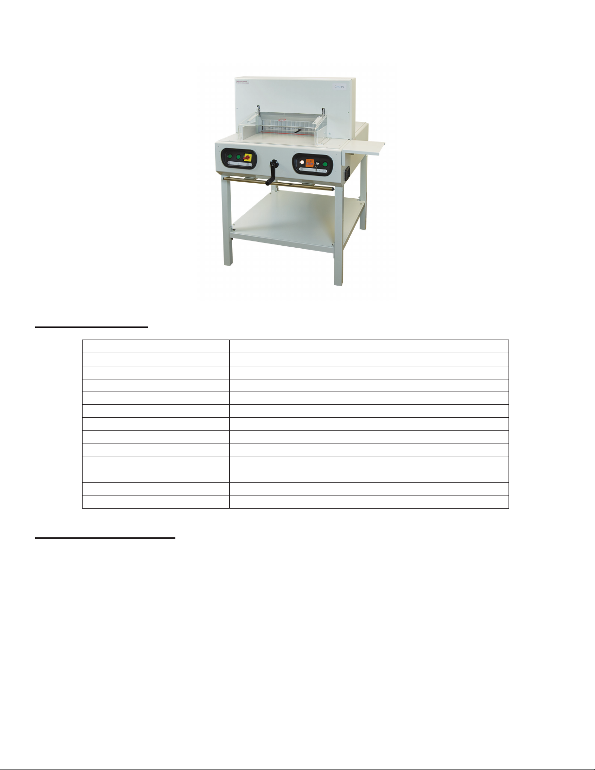
Cut-True 27S Guillotine Cutter
SPECIFICATIONS
Cutting Action: Dual-button electric
Maximum Cutting Width: 18.9” (480mm)
Maximum Paper Stack Height: 3.15” (80mm)
LED / Laser Cut Line: Yes
Clamp Style: Automatic
Back Gauge Adjustment: Manual crank
Back Gauge Reading: Digital readout, in both inches and metric
Blade Change Safety Tool: Included
Dimensions: 51” H x 36” W x 39” D (1300mm H x 920mm W x 1000mm D)
Weight: 595 lbs.
Power Supply: 110V
Safety Certications: CE approved, UL pending
Metal Stand with Shelf: Included, some assembly required
SAFETY GUIDELINES
* Operators should read this manual prior to using the cutter.
* The Cut-True 27S should only be used by one person at a time.
* Keep hands away from the cutting area. The cutter is operated by pressing two “enable switches” simultaneously.
* Do not disassemble Plexiglas safety covers, and never attempt to change the settings of any protective devices.
* Do not grasp underneath the blade edge.
* When changing the blade, carefully follow the instructions in this manual, and be sure to use the supplied Blade
Change Safety Tool. Wear leather gloves to provide additional safety.
* The Cut-True 27S is designed to cut only paper. DO NOT attempt to cut non-paper materials including metal sheets,
wood, plastic or anything other than paper. Machine damage and/or personal injury may occur.
* Be sure to check the safety devices before each operating session.
1
Page 5

INSTALLATION
Please use caution when moving the cutter, and be sure to utilize appropriate lifting devices
when attaching to the stand.
The cutter can be moved by using an overhead motorized lift, pallet jacks, or by hand.
NOTE: Four people are required to move the cutter by hand.
To move the cutter by hand, utilize
the lifting handles located on the front
and back of the machine. To adjust
the handles, loosen the knobs on the
underside and slide the handles to out
to a comfortable position. Retighten
the knobs.
When the cutter is in place and securely attached to the stand, loosen
the knobs, adjust the handles to
their storage position and tighten the
knobs.
Lifting handle
Adjustment knob Adjustment knob
Lifting handles
ASSEMBLY
The side panel, wooden paper pusher, blade safety device, and back gauge crank with screw are packed separately in
the box with the machine. Please set these aside and install after connecting the cutter to the stand.
The cutter should be installed in a location with sufcient space to permit efcient assembly, operation and maintenance.
Do not install in locations with direct sunlight or near a heat source.
The chassis and stand of the machine should be connected as follows:
1. Set the legs so the 4 threaded pins point upward.
2. Assemble the crossbars of the stand so the color labels on each match the corresponding legs. Fasten stand
securely with hexagonal screws.
3. Place the chassis correctly onto the assembled stand.
4. Tighten the four hexagonal nuts.
5. Position stand shelf in place and fasten securely with enclosed screws.
2
Page 6

OVERVIEW
21
1
2
3
4
5
6
2
7
11
8
9
10
12
13
14
15
16
17
18
19
20
22
23
10
24
DESCRIPTION OF EQUIPMENT PARTS
1. Cover Attached to the cutter with four screws. Disassemble only in case of blade
change or maintenance.
2. Enable Switches These switches must be pushed simultaneously to operate the paper clamp
and cutting blade.
3. Power Switch Used to turn on and off power to the cutter.
4. Back Gauge Crank Used to adjust back gauge to appropriate paper size and cut length. It is
indirectly connected with the Back Gauge: to engage the crank, simply
push it towards the machine, then turn. To release, pull the crank toward the
operator.
To move the back gauge toward the operator, turn clockwise.
To move the back gauge away from the operator, turn counterclockwise.
5. Power Light Shows when machine is powered on.
6. Key-Activated Mode Select Switch Turn to right for cutting. Turn to left for blade replacement. Turn to middle to
stop all operations.
7. Digital Measurement Readout Shows the current position of the back gauge, in mm and inches.
8. Rear Safety Cover Clear plexi cover is provided for operator safety and helps to prevent dust
buildup.
9. Front Safety Cover Prevents operators from placing hands or other objects in the cutting area.
Must be in the lowered/closed position in order to operate the cutter. The
guard can only be reopened when the blade is in the upright position.
10. Side Interlock Device A The cutter will not operate if the 6mm T-wrench used for blade adjustments
is still in the adjustment slot.
11. Side Panel Additional workspace.
12. Carrier (support) Carries the blade holder and the entire mechanism of the machine.
13. Safety Interlock Device B The machine can only be operated when the safety guard is closed.
14. Three Socket Headless Screws Adjustable screws for even cutting.
15. Cutting Blade Made of high-quality carbon steel.
3
Page 7

16. Paper Alignment Bars Steel side bar helps to align the paper prior to cutting.
17. Blade Holder Holds blade in place. There are ve screws for blade positioning, (which
should be set up and released step-by-step following the blade replacement
instructions) and adjusting the blade for even operation.
18. Cutting Stick Plastic stick which protects the edge of the blade during cutting. Can be
repositioned and used on all four sides before being replaced.
19. Cutting Stick Access Slot Insert screwdriver here in order to lift and remove cutting stick.
20. Stand Steel stand, assembly required.
21. Side Gauge with Scale In mm/cm and inches.The indicator on the back-gauge shows the mea-
surement. Fine adjustment is done via the back gauge crank (4). Minimum
adjustment is 0.5mm.
22. Back Gauge This is moved by rotating the Back Gauge Crank. Used to move the paper
stack into the appropriate cutting position.
23. LED Laser Cutting Line Shows operator exactly where the blade will cut the paper stack.
24. Blade Adjustment Access The blade height can be adjusted up to 2mm by using the adjustment screw.
To lower the blade (+), turn to the left. To raise the blade (-), turn to the right.
NOTE: If the blade is adjusted too low, it will cut deeply into the cutting stick,
damaging not only the stick but the cutting blade. The optimal blade height
is when the last sheet in a stack is cut accurately.
Wooden Push Block (not shown) Used to help align paper stacks for precise cutting.
Blade Change Safety Tool
(not shown)
Tool Kit (not shown) Includes T-wrench and interchangeable bits for use in adjustments and
This device is used to safely remove the blade when it needs to be
sharpened or replaced.
blade replacement.
OPERATION
1. Plug in the cutter to an appropriate power outlet.
2. Turn on the red power switch.
3. Raise the front safety cover. Slide the paper stack into the cutter along the left edge, using the alignment bar for
guidance. Push it as far back as possible toward the back gauge, without placing hands under the cutting blade.
4. To change the back gauge LED readout between standard and metric, insert
a pin or straightened paper clip into the access hole just above the LED, as
shown in the diagram at right.
5. Push in the back gauge crank to engage the handle, then turn it clockwise
to bring the back gauge toward the front until the paper is properly matched
with the measurement guide on the side of the machine. The LED digital
readout will indicate the position of the cut. The LED Laser Light will indicate
the position of the blade to help with paper positioning.
6. Release the back gauge crank handle by pulling it toward you. This disengages the crank and prevents unintentional movement.
7. Use the wooden push block to align the front and right edges of the paper stack.
8. Lower the front safety cover.
9. Turn the Mode Select Switch key to the right.
10. Press and hold the two clamp engage switches to clamp the paper securely in place. The clamp switches are
indicated by this icon
Insert pin
here
12.25
inch
cm
11. Press and hold the two blade engage switches to cut the paper. The blade switches are indicated by this icon
After cutting, the blade and clamp will each return to the upright position.
12. Lift the front safety cover and remove the paper stack.
4
Page 8

ROTATING / REPLACING THE CUTTING STICK
The cutting stick is the surface the blade contacts during the cutting process. It can be rotated and used on each side,
4 times altogether.
If the last piece of paper in the stack is not cut through cleanly, and the blade depth has been adjusted properly, the cutting stick should be rotated or replaced.
The cutting stick sits in a channel in the base of the cutter, just below the blade carrier. To remove it, rst turn off the
power. Then insert the 5mm screwdriver into the cutting stick access slot (see photo below left) and lift up. Grasp the
cutting stick and remove (see photo below right). Rotate the cutting stick to a new side and re-install.
NOTE: When the cutting stick is rotated or replaced, the blade height must be readjusted. See the next page for blade
height adjustment instructions.
ADJUSTING BLADE HEIGHT / CUTTING DEPTH
When the cutting stick is rotated or replaced, or the blade is replaced, the blade height must be readjusted. A blade which
cuts too deeply damages not only the cutting stick but the blade itself. The optimal blade height is when the last sheet in a
stack is cut accurately. The blade height can be adjusted up to 2mm.
1. The blade adjustment access is on the right side of the cutter, just behind the fuse panel (see picture, below left).
2. Slide the nger knob down and hold in place to open the access door.
3. Insert the T-wrench from the tool kit into the adjustment slot. To lower the blade (+), turn to the left. To raise the
blade (-), turn to the right.
4. NOTE: You must remove the T-wrench before operating to avoid injury or damage to the cutter.
Front of Cutter
GENERAL MAINTENANCE
All moving parts with screws should be checked periodically to be sure the screws are tight. They may become loose in
the process of transportation. Users should also check and tighten the screws after more than 200 cutting cycles.
All moving parts should be lubricated and oiled periodically to maintain performance and equipment life. Before lubricating, these parts should be cleaned to remove paper dust and old deposits of oil and grease.
5
Page 9

CUTTING BLADE MAINTENANCE
The cutting blade is made of heat-treated high-carbon steel and is designed for repeated use. However, over time the
blade will become dull, and not perform to the highest standards. Cutting heavy paper or cardboard will dull the blade
more quickly than thinner paper stock. A dull blade will not cut accurately. Blade lifetime with normal paper is approximately 1,500 cuts (tested in maximum capacity).
NOTE: If the blade jams in the paper stack or leaves a groove in the paper, it should be changed immediately.
If “CUT1500” appears in the LED display, the blade has completed 1,500 cutting passes. Check the blade to see if it is dull
or still sharp enough to cut through one sheet of copy paper.
If the blade is still sharp and does not need to be replaced, reset the counter with the following steps:
1. Turn the select switch key to the right.
2. Press and hold the right enable switch for at least 5 seconds, while simultaneously turning the select switch key
back to the middle position until the message “CAT” appears in the LED display.
3. Release the right enable switch.
If the blade is not making clean, accurate cuts, check the following:
* Have you rotated or replaced the cutting stick?
* Have you correctly adjusted the height of the blade?
If so, the blade will need to be replaced. The blade can either be re-sharpened by a professional, or it can be replaced
with a new blade. To avoid injury, follow the Blade Changing Procedure and use the Blade Change Safety Tool, included
with the cutter.
TROUBLESHOOTING
Blade doesn’t move Check if the main motor magnetic contact is activated.
No power Check power source and all control circuit fuses.
Overload Wait until the breaker automatically resets, which takes around 30-60 seconds.
The indicator light will be off. Reduce size of paper stack or change blade.
Cutter won’t operate after
closing front safety guard
Other issues Please contact your Formax dealer for service.
Press the two “enable switches” again, and check if the safety guard is completely
closed.
Blade Replacement Procedure
1. Remove screws at both ends of the cover.
Lift off and remove the cover.
Select switch in blade change position
2. Turn the power switch ON, and turn the select
switch to the left.
Power switch in ON position
6
Page 10

3. Press two enable switches simultaneously to
move the blade down to the bottom position.
4. Turn the select switch to the middle and turn
off the power. Then lift the plexi safety cover to
remove the rst screw from the right side of the
blade (A).
5. Close the safety cover and turn the select switch
to the left. Then turn on the power. The blade will
move up automatically. Turn the select switch to
the middle and turn off the power.
A
6. Raise the safety cover and remove the rst
screw from the left side (B). Remove the screws
to the left and right of center (C & D), but leave
the center screw in place.
NOTE: Do not remove the center screw.
7. Remove the blade change safety tool from the
tool box and screw the handles into the two holes
to the left and right of center (see photo). Screw
them in tightly, to prevent the blade from falling
out of the holder.
B C D
Center screw
7
Page 11

Blade change safety tool in place
8. Remove the center screw.
9. Grip and loosen both of the blade change tool
handles by turning just a half reverse turn to
remove the blade from the machine. Carefully
move the blade and holder downward in order
to remove it safely from the machine. NOTE: Be
careful to avoid injury from the very sharp blade.
10. Carefully remove the old blade from the blade
change safety tool. Set it on a at surface and
unscrew the handles. Cap the old blade with a
protective pad to prevent injury.
11. Place the new blade with the beveled cutting
edge facing up, and the screw holes at the top,
as shown here. Remove the protective pad
from the new blade.
To attach the blade change tool, place it over
the blade and screw the handles into the lower
set of screw holes. Then reverse the procedure
to install the new blade.
Beveled cutting edge
8
 Loading...