

Page 1

Formax Atlas C200 High-
Speed Automatic Creaser
Instruction Manual
Page 2

Atlas C200
Auto-Feed High-Speed Creaser
9/2016
OPERATOR MANUAL
First Edition
Page 3

INDEX
INTRODUCTION
SAFETYDo’s&Don’ts4
THE ATLAS C200
LabeledPhotograph
THECONTROLS
Theswitchpanel
Featuresontheswitchpanel
QUICKSTARTGUIDE9
OPERATING
Settingthemachine
Programmingthemachine
Readingstoredprogrammes
Paperjamming
PAGE3
6
7
7
20
26
27
29
THESTACKERASSEMBLY
SettingtheStackerunit
PERFORATING
Equipment,spares
Settingthemachine
THEBLADEASSEMBLY
Settingthebladepressure
Settingthebladealignment
REPLACINGCREASINGBLADESETS
Installingnewbladesets
Spares
TROUBLESHOOTING40
DISPATCHKIT48
ACCESSORIES&OPTIONS49
RECOMMENDEDSPARES50
FUSEPOSITIONSANDRATINGS52
PRODUCTRECYCLINGANDDISPOSAL53
30
32
33
35
36
37
39
Page2
CREASING
Page 4

INTRODUCTION
7hH$WODV&Lsafullyautomaticsuctionfeedingcreasing
systemdesignedforusewithbothconventionallithoanddigitalprinters.
ThefeedonthH$WODV&canalsobemanuallyoperatedforuse
withheavystock,verysmallorverylargesheets,embossedorevenirregular
sheets.
Thecreaseisprogrammedfromtheleadingedgeofthesheetusingthe
controlsonthefrontpanel.
Thebladeandanvilaremechanicallycontrolledovertheirentirelength
andcanbeadjustedtoaccommodatevariousweightsofmedia.
IMPORTANT
Theoperatingenvironmentshouldbecontrolledtoatemperaturebetween
16°Cand27°CMaximum
Specification
FeedingSystem................................................Bottomsuctionfeed
Max.SheetSize................................................700mmx500mm(27.5”x19.7”)[900mmx
500mm(35.4”x19.7”)withOptional
extensiontable].
Min.SheetSize(inautomaticmode).................210mmx140mm(8.5”x5.5”)
Max.PaperThickness........................................0.4mm(variesaccordingtohardness,
typeoffold,andsubstrate)
Max.No.CreasesperSheet............................16
Min.DistanceBetweenCreases.......................0.1mm
Max.No.StoredProgrammes..........................Unlimited
Min.CreaseDistancefromLeadingEdge........2.5mm
Min.CreaseDistancefromTailEdge................35mm
InHandFeedModeupto2499.9mmtoLastCreasecanbeProgrammed.
SpeedperHour(A4inhalf)..............................8500
SpeedperHour(A5inhalf)..............................11000
Dimensions.......................................................L:1500mmH:1224mmW:682mm
L:(59”)H:(48.2”)W:(26.8”)
Weight...............................................................156Kgs(+50Kgspacking)
PowerRequirement..........................................1phase230v50Hz
1phase220v60Hz
SoundPowerLevel................................78.5decibels
*Aspartofourcontinuedproductimprovementplan,specificationsandinformation
publishedinthismanualaresubjecttochangewithoutnotice.
Allspecificationsaredependantonapplication,typeofstock,temperature,RHandprint
engineused.
Specificationsquotedweremeasuredonuncoatedandunprintedstock.E&OE.
Page3SYSTEM
Page 5

SafetyDo’s&Don’ts
SafetyDo’s&Don’ts
REGLESDESECURITE:«AFAIRE»ET«ANEPASFAIRE»
Do-readthisoperatormanualfullybeforeoperatingthemachine.
Lirecemoded'emploiavantd'utiliserlamachine.
Do-operatewiththedesignatedACcurrentonly.Useanexclusiveoutlet,as
overloadingmaycausefireoranelectricshock.
Respecterl'alimentationélectriqueindiquée.Branchersurunepriseséparée
carunesurchargepeutentraînerunincendieouunchocélectrique.
Do-installthepowercordoutofthewaytoavoidatrippinghazard.
Installerlecordond'alimentationdemanièreànepaspouvoir
trébucherpardessus.
Do-makesurethatthemainsinletconnectorisalwayseasilyaccessible.
Ménagerunaccèslibreàlaprisedecourant.
Donot-installthemachineinanunstableplacesuchthatittiltsorshakes.
Nepasinstallerlamachinesurunesurfacenonplane,afind'éviter
qu'ellenepencheounevibre.
Donot-unplugtheplugorunplugthepowercordfromtheoutletwithawethand,
thiscancauseanelectricshock.
Nepasinstallerlamachinesurunesurfacenonplane,afind'éviter
qu'ellenepencheounevibre.
Donot-unscrewandremoveanycoversfromthemachine,asitcancausean
electricshockorinjury.
Nedémonteretenleveraucuncarterdelamachine,parcraintededécharge
électriqueoudeblessure.
Donot-placereceptaclescontainingliquidsonanysurface.
Nepasplacerderécipientcontenantunliquidesurlamachine.
Donot-adjustanypartofthemachinewhilstrollersarerunning
N'effectueraucunréglagependantquelesrouleauxfonctionnent.
Donot-operatethemachinewithlooseortrailingclothingorloosehair.
Nepasporterdevêtementsflottantsetrassemblerlescheveuxlongs
lorsdel'utilisationdelamachine.
Donot-underanycircumstancesadjustthepapergatewhenthemachineis
switchedon.
Enaucunecirconstance,réglerleséparateurdepapierlorsquela
machineestbranchée.
Page4
CREASING
Page 6
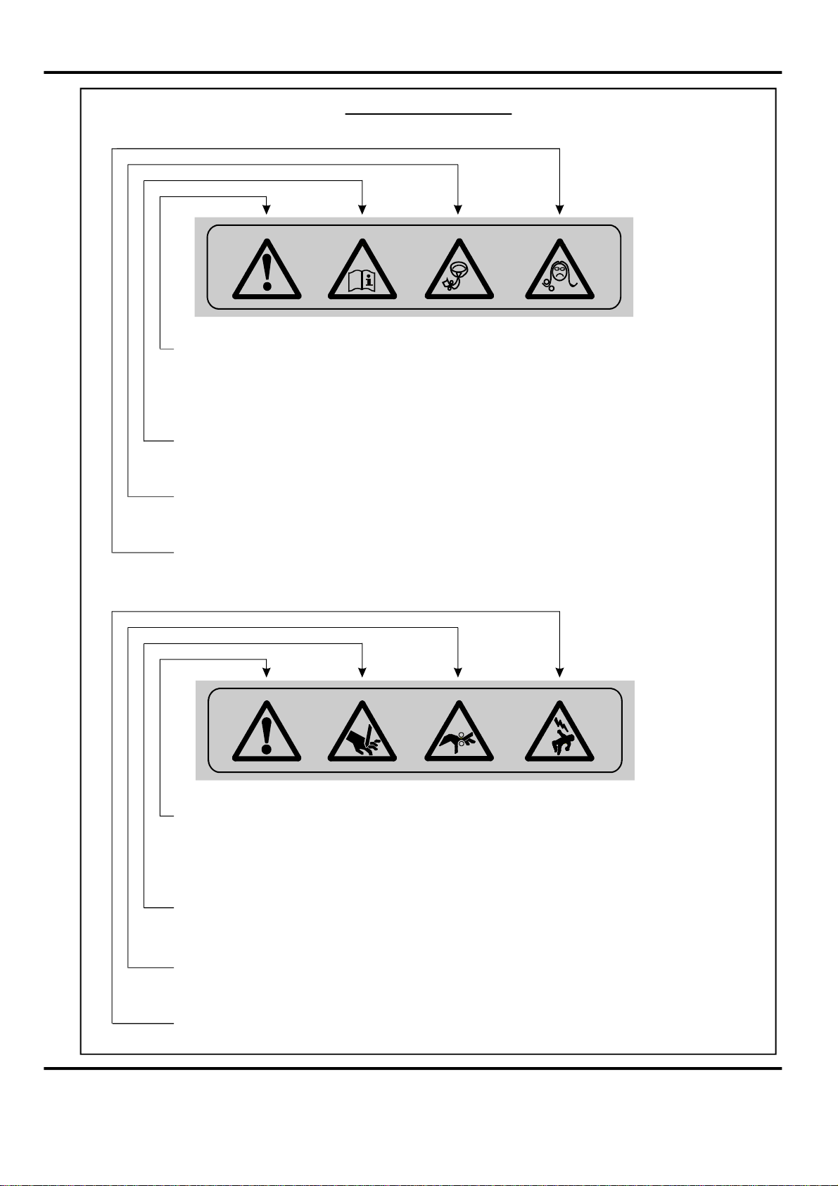
WarningLabels
Do-beawareofanyfingertrapsandrotatingpartswhenoperating
themachine.
Attentionaurisquedesecoincerlesdoigts,etauxpiècesen
mouvementlorsdufonctionnementdelamachine.
Do-readthisoperatormanualfullybeforeoperatingthemachine.
Lirecemoded’emploiavantd’utiliserlamachine.
Donot-operatethemachinewithlooseortrailingclothing.
Nepasporterdevêtementsflottantslorsdel'utilisationdelamachine
Donot-operatethemachinewithloosehair.
Rassemblerlescheveuxlongslorsdel'utilisationdelamachine.
Do-beawareofanyfingertrapsandrotatingpartswhenoperating
themachine.
Attentionaurisquedesecoincerlesdoigts,etauxpiècesen
mouvementlorsdufonctionnementdelamachine.
Do-beawareofsharppointsandblades.
Attentionauxélémentstranchantsetauxcouteaux.
Do-beawareofrotatingrollers.
Attentionauxrouleauxenfonctionnement
Do-beawareoflowcurrentanti-staticshock.
Attentionauxfaibleschocsd'électricitéstatique
Page5SYSTEM
Page 7
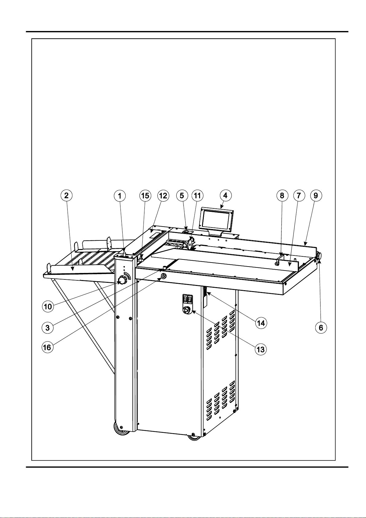
DOCUMENTCREASINGMACHINE
Keytophotographbelow
1Rollertilthandle7Adjustablesidelay13SwitchPanel
2Stackerassembly8BackStop14Fuses
3Suctionslotknob9Fixedsidelay15GapSetKnobandLever
4Touchscreen10Rollertiltknob16VacuumBleedKnob
5Airseparationknob11PaperGate
6Airdistributionknob12ExitGuard
Page6
CREASING
Page 8
THECONTROLS
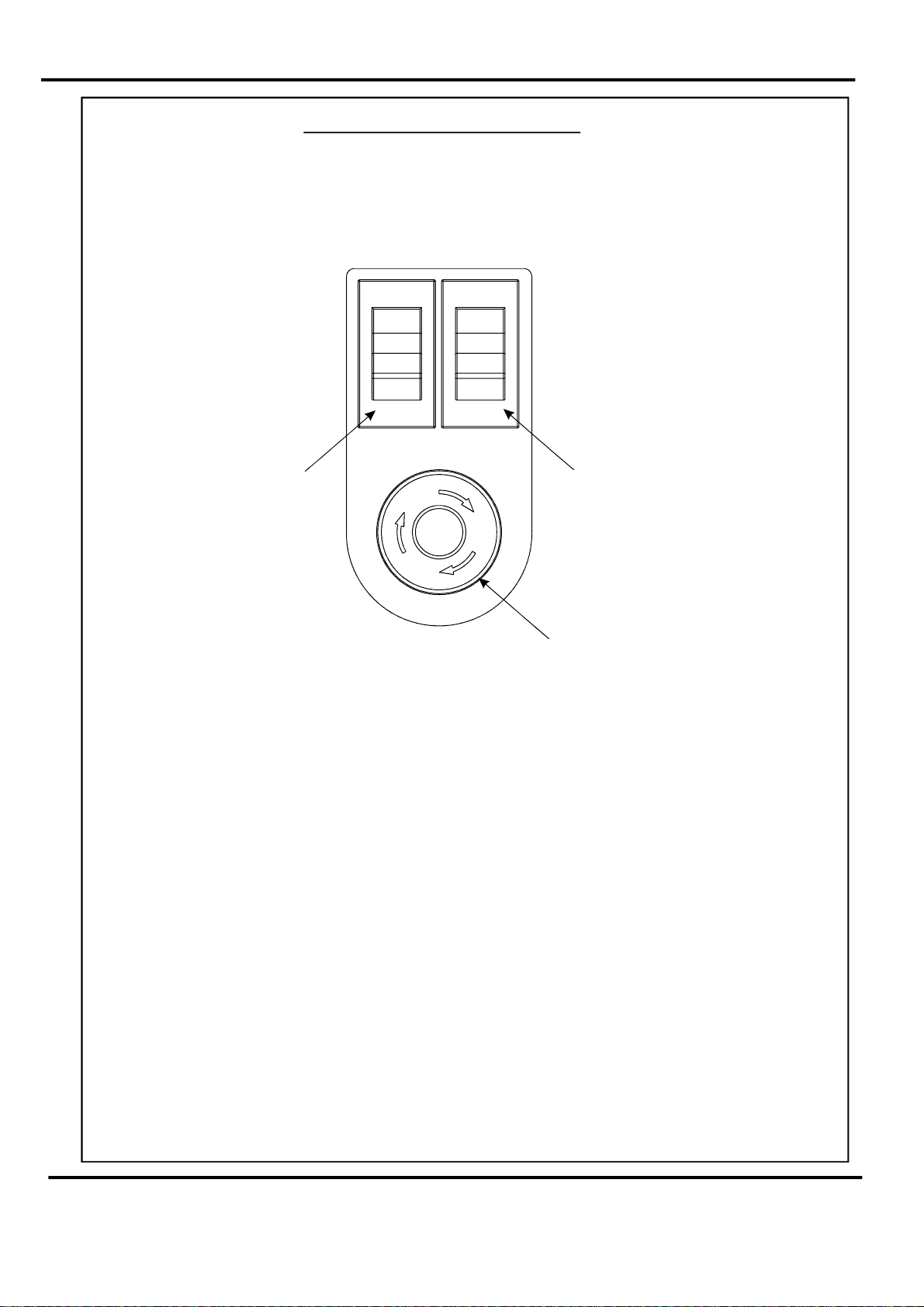
THESWITCHPANEL
TheSwitchPanelhouses
industrystandardEmergencyStopswitchwhichwillstopallpowergoingto
hemachinewhenactivated.
t
Co
mpressorSwitch
theCompressorswitch,Systemswitch,andan
SystemSwitch
EmergencyStopSwitch
FeaturesontheSwitchPanel
System
Whenactivat
creasin
Compressorswitch
Allowstheoperatortoswitchoffthecompressorunitinordertoutilisethemachine
tomanuallyfeedsheets.
switch
edthesystemswitchwilloperatethemotorsinordertobeginthe
gsequence.
Page7SYSTEM
Page 9

THECONTROLS
BLANK
PAGE
Page8
CREASING
Page 10

QuickStartGuide
Settingthemachinetooperateinautomaticsheetfeedmode
1.Setthegapbetweenthepapergateandthevacuumrollertoapproximatelytwice
thethicknessofthestocktobecreased.
2.Placethestocktobecreasedontotheloadingtableagainstthefixedsidelay.
3.Releasetheclampsontheadjustablesidelayandslideuptothepaperstack
allowingagapofapproximately0.5mm(1/64inch)betweenthepaperandtheside
lay.
4.Positionthebackstopandslideituptothepaperstack,alsoallowingagap(as
statedintheabovestep).
5.TurntheEmergencyStopbuttonclockwisetoswitchthepoweron.Afterthe
systemstartupprocedurethetouchscreenwillbedisplayedasshownbelow.
IMPORTANT.
Ifyouhavenotbeentrainedtooperatethismachine,westronglyadvisethatyouselect
theredcrossicon.
Werecommendthatyoueitherseektrainingoraskatrainedoperatortorunthemachine
foryou.
Selectthegreentickicononlyifyouhavebeentrainedtooperatethismachine.
Ifyouhavenotbeentrainedtooperatethismachineandyouselectthegreentickicon,
)RUPD[acceptnoresponsibilityforpersonalinjury,damagetothe
machineordamagetomaterialsbeingprocessedbythemachine.
WARNING:-
Waitatleast10seconds,aftermakinganyselectionontheTouchscreen
panel,beforeswitchingthemachineOFF.Failuretodosocouldresultinthe
datastoragebeingcorrupted,andthemachinenotoperating.
Page9SYSTEM
Page 11
QuickStartGuide
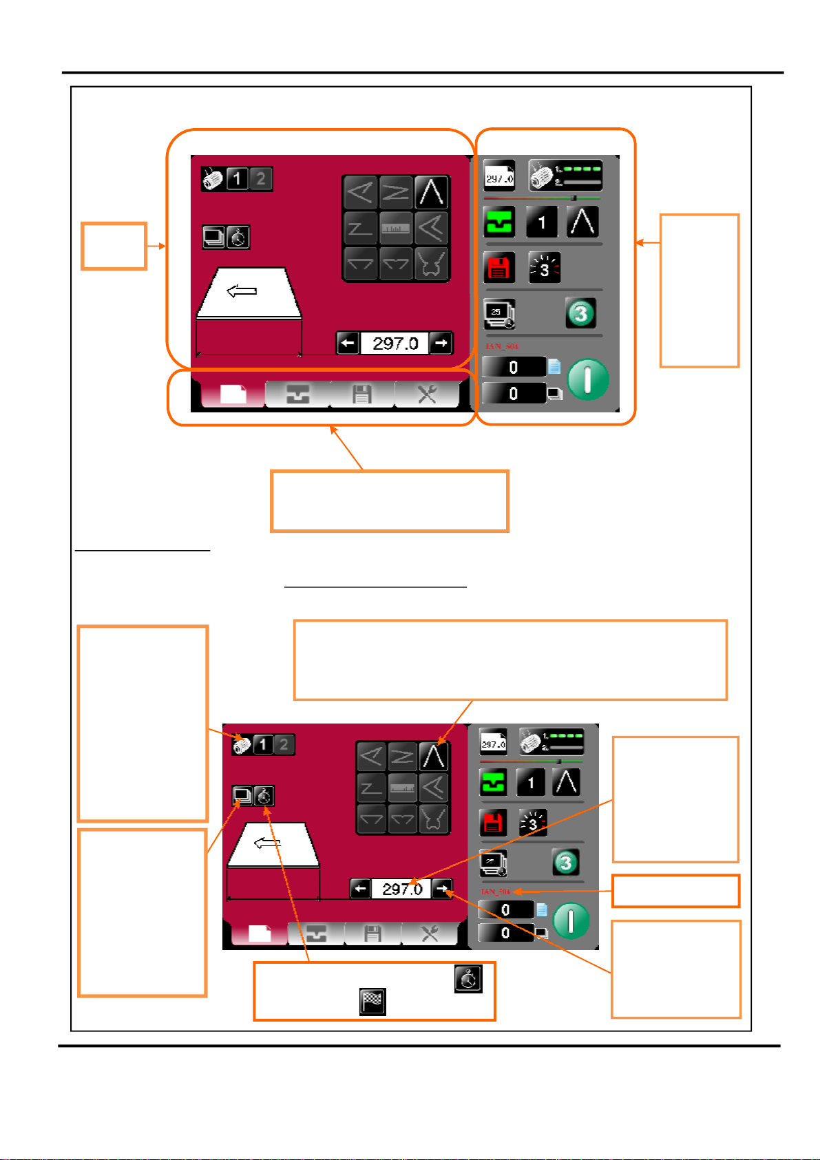
Thetouchscreenislaidoutinto3mainareasasshownbelow:
Setting
page
SettingsPages.
Tabstoenableswitchingbetweensetting
chooseeitherPaper
pages
-
CreaseSetting,StoreorTools
Settings,
PaperSettingsPage.
Statusof
machine
dataentry
area.Also
usedfor
quicklinks
tosetting
pages.
&
VacuumSuck-There
aretwoselections
available-1short
suck&2continuous
forstreamfeeding.
Highlightednumberis
typecurrently
selected.Thestatus
areaalsoshows
currentlyselected
suck.
BatchButton-Image
isidenticaltothat
showninthestatus
area.Onselectionthe
statusareaisreplaced
withacalculatorfor
inputtingnewvalues.
Batchesofany
numericalvalue.
FoldSelection-Forquicksettingofcreasepositionsonstandardsizesheets.
Highlightedfoldistypecurrentlyselected,otherfoldsmaybeselected.
Currentlyselectedfoldisshowninthestatusarea.
Togglebetween,Delaybetweenbatches
andstopafterbatch
PageLength - On
selectionthestatus
areaisreplacedwith
acalculatorfor
inputtingnewvalues.
MinLength=190mm
CurrentJobName
Arrowsmaybe
selectedtoincrease
ordecreasethepage
sizein0.1mm
increments
Page10
CREASING
Page 12
QuickStartGuide
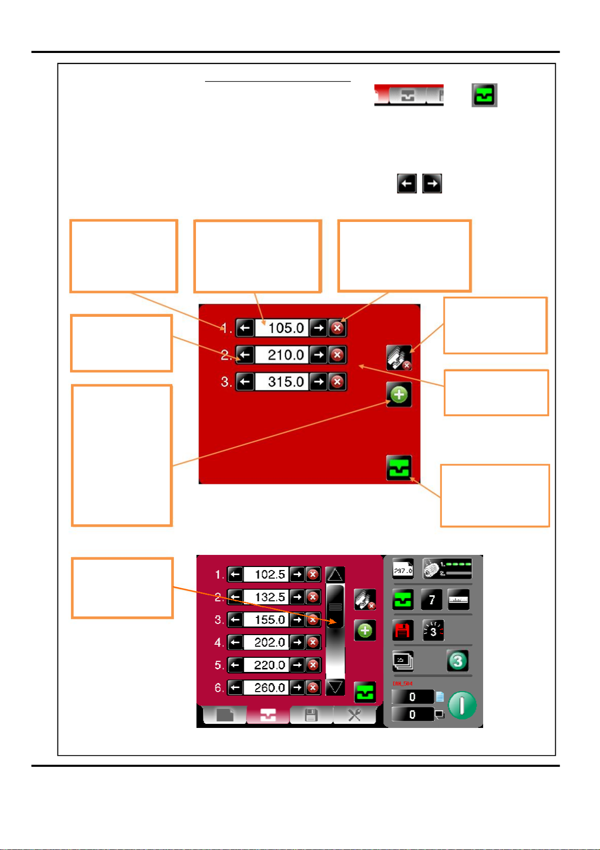
CreasesettingsPages.
Togettothecreasesettingpageclickthelowertaborfrom
thestatusarea.
Ifyouhaveselectedapredefinedstandardcreasetypefromthepapersettings
pagethecreasepositionswillbesetforyou.Thesepositionscanbefinetuned
by±0.1mmincrementsbypressingsidearrowbuttonsforeachcrease.
Numberofcreases–if
morethan6creasesare
addedascrollbarwill
appeartoenable
viewingofallcreases
Arrowsmaybeselected
toincreaseordecrease
thecreaseposition
in0.1mmincrements
Plusboxforinserting
additionalcreases.On
selectionfollowing
creaseswillmovedown
byoneplacea
maximumnumberof6
creasescanbeseenat
anyonetimefurther
creasescanbe
accessedbyuseofthe
scrollbar.
Creaseposition-Onselection
thestatusareaisreplacedwith
acalculatorforinputtingnew
values.
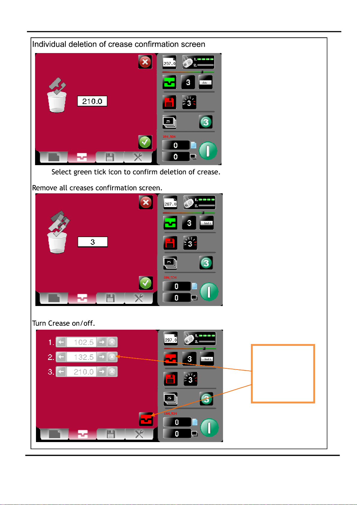
Crossboxfordeletionofcrease.
Ondeletionofcreasefollowing
creaseswillmoveupbyone
place.Youwillbeaskedto
confirmdeletionofthecrease.
Presstoremoveall
creases–youwillbe
askedtoconfirm
deletion.
Scrollbar-usetobring
requiredcreaseinto
view.
Creaseon/offselector
greenison&redisoff.
Thisisalsoindicatedin
thestatusarea.
Additionalcreases
added–scrollbar
appearsformorethan
sixcreases.
Page11SYSTEM
Page 13
QuickStartGuide
Page12
CreasingturnedoffGreyedoutareasare
unselectable.Status
areawillshow
creasingisoffwith
redicon
CREASING
Page 14
RunJob
SystemSwitchNotOn
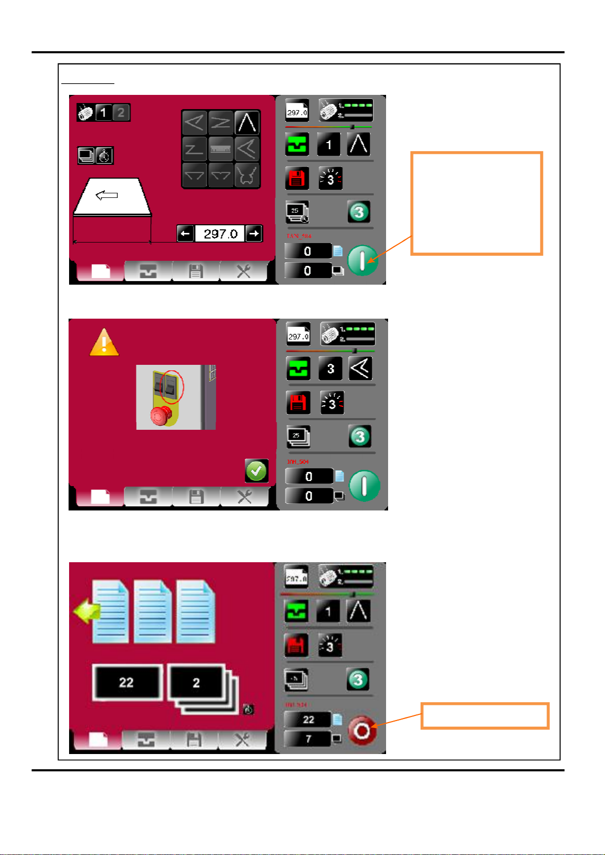
QuickStartGuide
Clicktostartmachinewith
settingscurrentlyshown-
youwillreceivea
notificationifsystem
switchisnoton.Press
againtostopJob
PushSystemSwitchdowntostartthemachine.
Themachinerunningscreenwillappear.
Clicktostopmachine
Page13SYSTEM
Page 15
QuickStartGuide
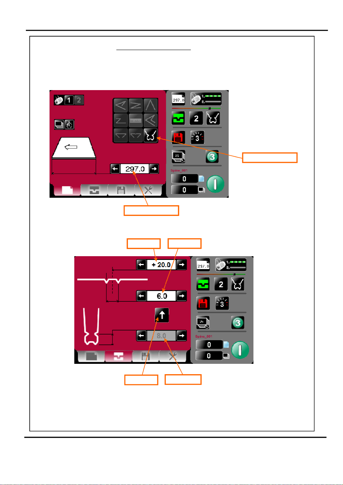
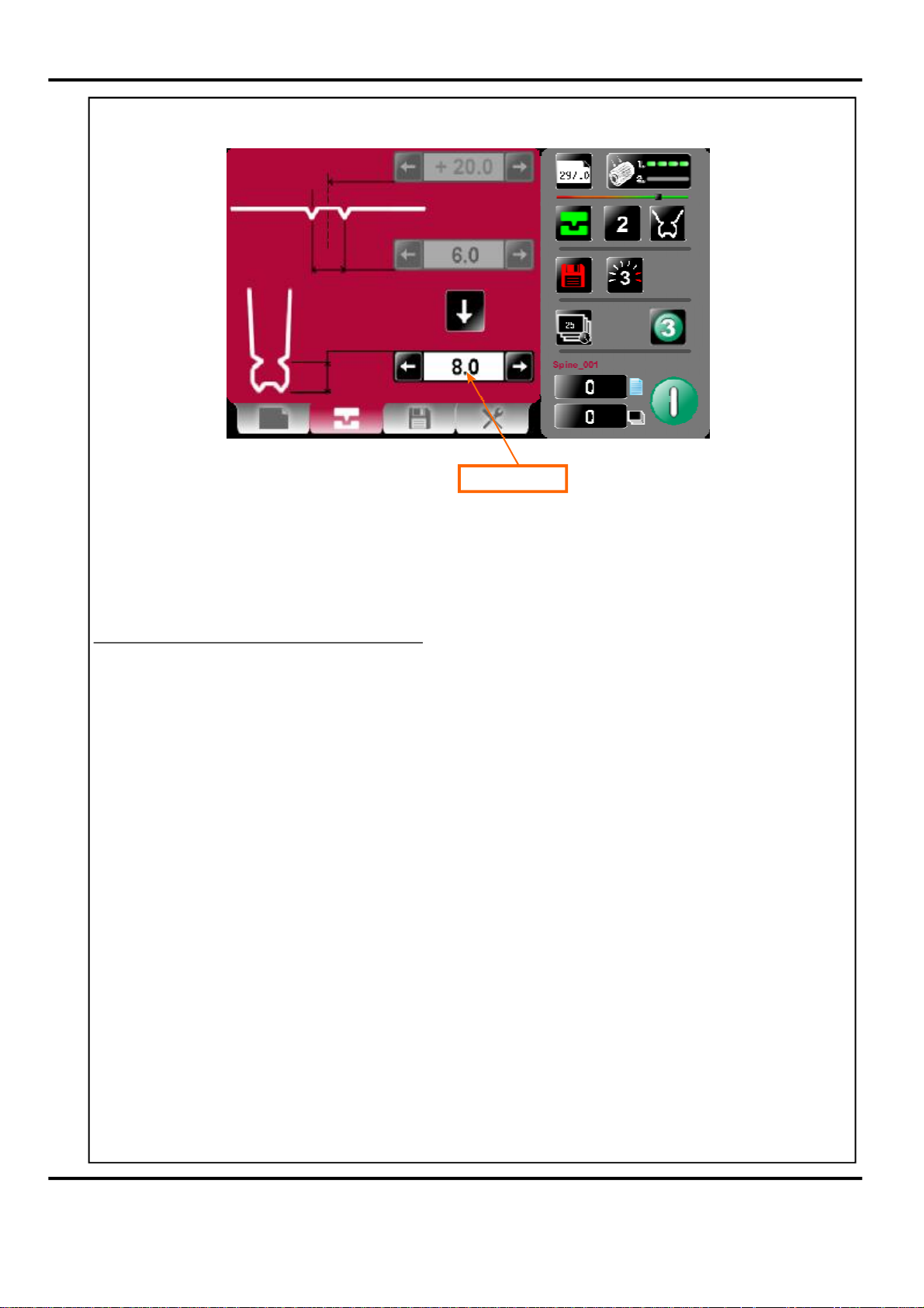
CoverCreaseMode.
1.SelectthePaperSettingsTab.
2.EnterthePaperLengthandthenselecttheCoverCreasebutton.
CoverCreasebutton
PaperLength
3.SelecttheCreaseSettingsTab.
SpineOffset
SpineWidth
ArrowButton
HingeDistance
4.EntertheSpineWidthdimension.Ifnecessary,adjusttheSpineOffsetfromthe
centreofthesheet.
5.SelectthearrowbuttontosetthehingeDimension.
Page14
CREASING
Page 16
6.EntertheHingeDimension.
QuickStartGuide
HingeDimension
7.SelectthearrowbuttontohighlighttheSpineOffsetandtheSpineWidth
dimensions.
8.RunthesheetsofpaperthroughthemachinetomaketheSpinecreases.
TOMAKETHEHINGECREASES.
9.Removethesheetsofpaperfromthestackertray.,
andputthembackontotheloadingtable.
OFTHESHEETSPOINTINTHESAMEDIRECTIONASBEFORE.
10.SelectthearrowbuttontohighlighttheHingeDimension.
11.RunthesheetsofpaperthroughthemachinetomaketheHingecreases.
MAKESURETHATTHELEADEDGE
TURNTHESHEETSOVER
Page15SYSTEM
Page 17
QuickStartGuide
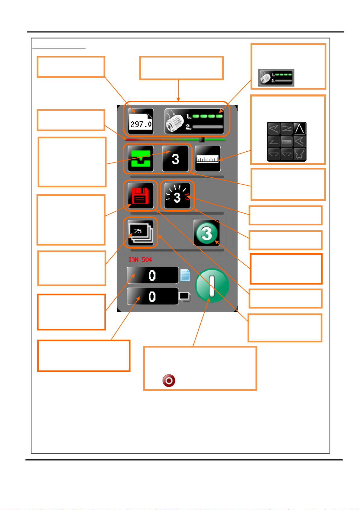
StatusScreen
Paperlength-inputfrom
thepapersettingscreen
LeadEdgeSensorStrength,
IndicatorBar
Numberofcreases-this
mayalterautomaticallyif
apre-definedfoldis
selected.Adjustments
maybemadeinthe
creasesettingscreen
Greeniconindicates
settingsaresaved-ared
iconwouldshowthat
settingshavebeen
changedbutthejobhas
notbeensaved.
Clickinginthisareawilltakeyou
tothepapersettingpage
CurrentlyselectedVacuum
Sucksetting-forstream
settingchooseselection2
Currentlyselectedfoldtype
-canbeoneofthe
following.
Clickinginthisareawilltake
youtotheCreasesetting
page
Currentmachinespeedsetting
Clickinginthisareawilltake
youtotheToolspage
Batchquantity-thisis
inputfromthebatch
calculatoronthepaper
settingscreen-max.999
Sheetcount-clicktozero
Ascreenwillappearto
confirmthatyouwantto
resetthecount.
Batchcount-clicktozero
Ascreenwillappeartoconfirmthat
youwanttoresetthecount.
Selectthisbuttontoproduce
3testsheetswiththe
settingscurrentlyshown.
Clickinginthisareawilltake
youtotheJobStorepage
Clickinginthisareawilltake
youtothepapersetting
page.
Clicktostartmachinewithsettingscurrently
shown-youwillreceiveanotificationif
systemswitchisnoton.Pressagaintostop
Job
Page16
CREASING
Page 18

QuickStartGuide
TheStatusScreenwillonoccasionsbereplacedwithanInputCalculatorScreen
asshownbelow.
Pre-setPapersizesforquick
insertion–Standardsizesfor
countryoriginwouldbeshown
PapersizeBatchsizeCreaseposition
inputcalculatorinputcalculatorinputcalculator
Pre-setBatchsizesforquick
insertion.
NOTE:
ThegreentickortheredcrossmustbeselectedontheCalculatorScreento
makethelefthandsideofthetouchscreenactiveagain.
Page17SYSTEM
Page 19

ToolsScreen
Inchpaperindirection
ofarrowtoclearjams
QuickStartGuide
MachineSpeedAdjustment:Speedsetting3willgivethefastestthroughputof
stockthroughthemachine.
Usespeedsetting1or2fortroublesomestocks,
ortosynchronisethespeeĚ
ClickonUpArrowto
putAnvilintoTop
DeadCentreposition
(TDC)
CleanLeadEdgeSensor
TouchScreenCalibration
SeePage19
ChangeMachinemeasurement
settings,Imperial/Metric
Inchpaperindirection
ofarrowtoclearjams
Clickingthisiconwill
showMachine
programrevision&
TouchScreen
softwarerevision.
Page18
Touchscreensoftware
version
MainProcessorProgram
version
CREASING
Page 20

QuickStartGuide
TouchScreenCalibration.
1.Switchthemainspoweronandwaitforthemainscreentoappearbefore
commencingtocheckthehorizontalandverticalpositionofthedisplay.
Thepositionofthedisplaywithinthesurroundisachievedbyoperatingthebutton
attherearofthehousing,pressthisanumberoftimestoobtainthecorrect
orientationrequired,movetothenextbuttontomovethepositiontocentralize
horizontal.
2.(i)Selectthetoolsmenutab,andthenSelecttheTouchScreencalibrationicon.
(ii)Usingaplasticpointer,softleadedpencil,birocapetc.andwithgentlepressure.
TouchthecentreofthecrossineachcorneroftheTouchScreen,asprompted,by
thehandgraphics.ThisprocedurewillcalibratetheTouchScreen.
Page19SYSTEM
Page 21

SettingtheMachine
AdjustingthePaperGate
SettheheightofthePaperGatetoapproximatelytwothicknessesofpaper,byturningthe
discj.Anexcessivegapisamostlikelycauseofdoublesheetfeeding.
Thissettingisonlyintendedasaguide,forinstance,sheetswithanupwardcurlwill
requirethissettingtobeincreased.
J
TWOTHICKNESSES
OFPAPER
WARNING.
DONOTADJUSTTHE
PAPERGATEWHILETHE
MACHINEISRUNNINGOR
THESUCTIONDRUMMAY
BECOMEDAMAGED.
SettingtheSuctionSlot
Thesuctionslotislocatedinsidethevacuumrollerandcanbeadjustedbyreleasingand
movingthesuctionknobhorizontallyineitherdirectiontotherequiredposition.
Forlightstockssettheknobtotheleftandforheavierstockssettheknobtotheright.
FIG8.1
Adjustable
SideLay
Suction
SlotKnob
Page20
CREASING
Page 22

SettingtheAdjustableSideLay
Placethepaperstackontotheloadingtableandslideuptothefixedsidelayandpaper
gate.Releasetheclampslocatedateachendofthesidelayandslideuptowardsthe
paperstackasdemonstratedinfig8.1.Allowagapofapproximately0.5mm(1/64inch)
betweenthepaperandthesidelay.
SettingtheBackStop
Positionthebackstopandslideuptowardsthepaperstackallowingagap(asspecified
intheabovestep).
SettingtheAirDistribution
Dependingonthelengthofthesheettobecreased,theairdistributionknobcanbe
rotatedtovariouspositionsinordertosupplyairtodifferentports.Position2is
recommendedformostsheetsizes.However,abetterresultmaybeobtainedbyusing
thesettingsbeloworbyexperimentation.
Position1-
2345-
0-
Port1
ForsheetslongerthanA3(17”)inordertosupplyairtothecentreofthe
stack,ports2,3and4open.
ForA5sheetsor8incheslong,ports1and2open.
ForA4sheetsor11incheslong,ports1and3open.
ForA3sheetsor17incheslong,ports1and4open.
ForsheetslongerthanA3(17”)inordertosupplyairtotheendsofthestack,
ports1and5open.
ForsheetslongerthanA3(17”)inordertosupplyairevenlyalongthestack,
ports1,3and5open.
Port5
AirDistribution
KnobShown
SetToPosn.1
SettingtheAirSeparationPressure
Tocontroltheamountofairsuppliedtotheports,theairseparationknobcanberotated
clockwisetodecreasethepressureoranti-clockwisetoincreasethepressure.
Page21SYSTEM
Page 23

SettingtheRollerTiltMechanism
Therollertiltmechanismhasbeendesignedtocompensateforwhenthecreasing
positiononthesheetisnotsquare.Thiscouldbeduetoaninaccuracyinthemediaorif
therollertiltmechanismhasbeenincorrectlyset.Themechanismwillbesettozero
(square)whenthemachineissupplied.
Tosetthemechanism,unlocktherollertiltknoblocatedbelowtherollertiltinghandleby
turninganti-clockwise.Movetherollertilthandleleftorrightinordertocompensatefor
anyinaccuracy.Whenthepositionisset,ensuretolocktherollertiltknobbefore
operatingthemachine.Repeattheaboveprocedureuntilthecreasingpositionissquare.
Settingthepositionsofdrivewheelsandhubs
Itisimportantthatthedrivewheelsanddrivehubsontherollershaftsarearrangedevenly
acrossthewidthofthemediabeingcreased.Thisisdonetoensurethatthemediais
accuratelydrivenandsupportedthroughtherollers.
Thedrivewheelsandhubsarefixedtotherollersbymeansofagrubscrew.Tolocatethis
grubscrewtherollerscanberotatedbyoperatingthemotormanually.
DONOTROTATETHEDRIVEROLLERSBYHAND.
Tooperatethemotorsmanually,switchthemachine‘on’attheEmergencyStopswitch.
SelecttheToolstabatthebottomofthetouchscreen,thedisplaywillchangeto
thatshownbelow.
Inchpaperindirection
ofarrowtoclearjams
Pressthesystemswitchdownandthenselecttherightorleftarrows,torotatetherollersin
shortpulses.
Lifttheexitguardtoseeifthegrubscrewsinthedrivewheelsandhubscanbeseen.Ifthe
grubscrewscannotbeseen,lowertheexitguardandrotatetherollersbyselectingthe
rightorleftarrows.Loosenthedrivewheelsandhubswitha2mmallenkey.Arrangethe
drivewheelsandhubsasshowninFIG10.1.Inordertoavoidmarkingonsometypesof
mediaensureagapbetweenthedrivewheelsandhubs.
Thisprocedureshouldberepeatedwheninstallingperforatingbladesandanvilsontothe
drivewheelsandhubs.
Leftarrow
Inchpaperindirection
ofarrowtoclearjams
Rightarrow
Page22
CREASING
Page 24

FIG10.1
SetFeed
Thelengthofsuctiononthesheetofpaperbeingfedcanbeadjustedbysettingthefeed
typeasfollows:-
Select1forshortsuck,select2forcontinuoussuck(streamfeeding).
VacuumSuck
Select1forshortsuck
Select2forcontinuoussuck
(Streamfeeding)
NOTES.
1.willgivethequickestthroughputofstockthroughthemachine.
StreamFeed
2.Whenthefirstcreaseislessthan37mmfromtheleadingedgeofthepaperthefeedwill
benoticeablyslowerwhenusingspeeds2and3.
3.Whenthefirstcreaseislessthan50mmfromtheleadingedgeofthepaperthefeedwill
benoticeablyslowerwhenusingspeed3.
Page23SYSTEM
Page 25

Settingtheinfeedrollergapset
Thegapbetweentheinfeedrollersmustbeadjustedtosuitthestockbeingused.Thegap
setcanbeadjustedasfollows:-
1.Placeasamplesheetofthestocktobeusedontothefeedbed.
2.SelecttheToolstabatthebottomofthetouchscreen,thedisplaywill
changetothatshownbelow.
3.Pressthesystemswitchdownandthenselecttheleftarrowonthetouchscreen,to
rotatetherollersinshortpulsesuntilthesheetisgrippedintheinfeedrollers..
4.Testthegripofthesheetintherollersbytryingtoremovethesheetbyhand,the
sheetshouldbelightlygrippedbytherollers.Ifthegriponthesheetistoolightortoo
heavyitcanbeadjustedasfollows:-
(i)Turnthegapsetlockingknobanti-clockwisetounlock.
(ii)Movethegapsetleveruptoincreasethegapordowntodecreasethegap.
(iii)Turnthegapsetlockingknobclockwisetolock.
GapSet
Lever
GapSet
Locking
Knob
Page24
CREASING
Page 26

Page25SYSTEM
Page 27

Programmingthemachine
1.Switchthepower‘on’byturningtheEmergencystopbuttonclockwise
toreleasethesafetylatch.
Settingthepagelength
2.Setthepagelengthofthepaperasdescribedonpage10.
Settingthevacuumsuck
3.Setthevacuumsuckasdescribedonpage10.Settingnumber1forshortsuckand
settingnumber2forcontinuoussuck(streamfeed).
Settingthebatchquantity
4.Selectthebutton.Onselectionthestatusareaisreplacedwithacalculatorfor
inputtingnewvalues.
Settingthecreasepositions
5.(i)Selectthelowertaborfromthestatusareatogettothe
CreaseSettingsPage.
(ii)Setthecreasesasdescribedonpages11and12.
StoringtheJob
6.Thejobthathasbeensetcannowbestoredasfollows.
(i)Selectthelowertaborfromthestatusareatogettothe
StoreSettingsPage.
(ii)Thejobcanbegivenanameandstoredasdescribedbelow.Youcanalsoretrieve
previouslysavedjobs,modifythemordeletejobsthatarenolongerrequired.
Tocreateanewjobnameclickintextarea&
keyboardwillopentoinputjobname.
Loadexistingjobfrom
store
Clickingtosearch
currentlystoredjobs
Clickingtodelete
currentlystoredjobs
Page26
CurrentJobName
YellowTextDenotesSavedJob
RedTextDenotesUnsavedJob
Clickingtosavejob
shown.
CREASING
Page 28

Keyboardf
orenteringjobname.
Saveconfirmationscreen.
DeletelastcharacterDeleteallcharacters
clicksav
jobtostore
eicon
tosave
Toconfirmsaving
ofJobclickhere.
Searchforcurrentjobstoloadormodify.
Youcansearchforjobsbyclickingthesearchicon,thiswillbringupthesearch
keyboardfortextinput.
Typeinjobdescription
o
rfirstfewcharacters
Presssearchicon
tostartsearch
Tochangeyourmind&
ret
urntotheprevious
screenclickhere.
Page27SYSTEM
Page 29

Jobsmatching
charactersintextbox
willbeshowninthis
area-selectingjob
fromthisareawill
showjobsettingsin
therighthandstatus
area.Jobselectedwill
beshownintextbox.
Loadingjobconfirmationscreen.
Togglebetweensearch
results&fulllistof
jobs
Presstoloadjob
shownintextbox.
Theloadedjobcanberunormodifiedandsavedasthesamejobname.
Overwritejobconfirmationscreen.
Tocanceloverwriteof
Jobpresshere.
Toconfirmoverwrite
ofJobpresshere.
Page28
CREASING
Page 30

Deletejobconfirmationscreen.
Tocanceldeletionof
Jobpresshere.
Toconfirmdeletionof
Jobpresshere.
Runningthemachine
Runthejobasdescribedonpage13.Themachinewillcompleteitscreasingoperationifa
sheethasalreadybeenfedthroughthepapergate.
Paperjamming
Intheeventofapaperjamoccurringwhilstthemachineisoperating,selecttheTools
tabatthebottomofthetouchscreen,thedisplaywillchangetothatshown
below.Pressthesystemswitchdownandthenselecttherightorleftarrows,toinchthe
paperforwardsorbackwards.
Inchpaperindirection
ofarrowtoclearjams
Inchpaperindirection
ofarrowtoclearjams
Settingthemachinetooperateinmanualsheetfeedmode
Inordertofeedheavystock,verysmallorverylargesheets,embossedorevenirregular
shapedsheets,itmaybenecessarytofeedthesheetsmanually.Themachinecanbe
programmedandsetupinexactlythesamewayasexplainedwhenoperatingthemachine
automatically.However,thepapergatemustberaisedtoitshighestpositionforthesheets
tobefedfreely.Operatingthemachineinmanualsheetfeedmodewillalsorequirethe
suctionlengthtobecontinuousinordertoaccommodatevarioustypesofstock.Therefore,
thefeedshouldbesetto(VacuumDrumposition2)seepage10.
ThemachinecannowbestartedbyactivatingtheSystemswitchto‘on’.
theCompressorswitch.
StreamFeed
Donotactivate
Selecttheicononthetouchscreenandbegintoslidethesheetsindividuallythrough
thepapergateuntiltheyaredrivenbythedrivebelts.
Tostopfeedingthesheets,selecttheicononthetouchscreenandswitchthe
SystemSwitchoff.
Page29SYSTEM
Page 31

TheStackerAssembly
Thestackerunitonthemachineisusedtocatchthesheetsoncetheyhavebeen
creasedorperforated.
SettingtheStackerassembly
1.Assemblethestackerunittothemachineasshowninfig13.1below.
Important
Ensurethatthestackerunithasbeenassembledtothemachineproperly.However,
ifithasnot,theconnectiononthemagneticswitchwillbebrokenandthemachine
willnotoperate(seeTroubleshootingpagesfordetails).
Therearetwosideguidesonthestackerunit;alefthanded(fixed)guideandaright
handed(movable)guideheldonbyamagneticstrip.Thereisalsoalefthandextension
guide.Theguideswillcontrolthewayinwhichthepaperiscollatedbysettingtheir
positionsonthestackerbed.
2.Placeasinglesheet(fromthestacktobecreased/perforated)ontothestackerbed
againstthefixed‘lefthand’guide.
3.Positionthe‘righthand’sideguideontothestackerbedleavingaminimum
clearanceofapproximately1mmeachsideofthesheet.
LEFTHAND
BACKSTOP
LEFTHAND
SIDEGUIDE
Page30
RIGHTHAND
SIDEGUIDE
RIGHTHAND
BACKSTOP
CREASING
Page 32

TheStackerAssembly
4.Whilstthesheetisbetweenthetwoguidesonthestackerbed,setthedistance
betweenthetopofthesheetandthebackstopflangestoapproximately5mm.
5.Forshortersheets,thebackstopcanbeused(asshowninFIG13.1)toadjustthe
positionofthepaperstack.
TIPS
l
Oneofthebackstopssuppliedwiththemachine(onthe
stackerassembly)canalsobeusedasatoolholderas
demonstratedinthephotograph(left).
l
Thescaleonthebedcanbeusedtomeasurethedesired
creasingorperforatingpositiononthesheet.
Page31SYSTEM
Page 33

Perforating
Note
Perforatingandcreasingcanbecarriedoutsimultaneously.However,ifany
adjustmentismadetotherollertiltmechanisminordertocompensateforthe
perforationlinebeing’outofsquare’,thismayeffecttheaccuracyofthecrease.If
thisoccurscreasingandperforatingmustbecarriedoutasseparateoperations.
Thecomponentsandtoolsrequiredtoinstalltheperforatorarecontainedinthedespatch
kitsuppliedwiththemachine,theyarelistedbelow.
1offSetofstandardperforation‘56tooth’blades.
1offSetofstandardhardenedanvils.
1offPerforatorstripper.
1off3mmbondhuswrench/allenkey
1off2mmbondhuswrench/allenkey
Theperforatorbladesaresplitintotwomatchinghalves
andarefittedtothedrivewheelsasshowninthe
photographusingthefourscrewssupplied.
Ahardenedanvilisfittedtothedrivehubasshowninthe
photographalsousingthefourscrewssupplied.Againthe
anvilsaremadefrommatchinghalves.
Important:Theperforatorbladesareverysharpand
caremustbetakenwhilsthandling.
Donotmixthematchingpairsofbladesoranvils.
Perforating‘Spares’kits
Forperforatingandothertypesofpaper,variousspareskitsareavailablewhichcanbe
assembledtothemachineinthesamefashion.Theyarelistedbelowalongwitharange
ofscoringwheels,
Perforatingblades1-99-41
Anvils1-99-35
56teethPartNumber-Standardstock/
fineperforations.
28teethPartNumber-Mediumstock/
20teethPartNumber-Heavystock/
StandardPartNumber-Forallbladetypes
1-99-12
mediumperforations.
1-99-10
coarseperforations.
Page32
CREASING
Page 34

Allofthebladesandanvilsaresuppliedwithfixings.
Perforating
*Perforatorstripper78-013
*Itisrecommendedthatformultipleperforations,aseparateperforatorstripperisusedfor
everyperforatingbladesetfittedinthecreasingunit.
StandardPartNumber
Settingthemachine
1.Turnthemainssupplytothemachine‘off’.
2.Removethestackerunitandopentheexitguard.
3.Locateandremovetheblades/anvilsfromthedespatchkitsuppliedwiththe
machine.
4.Usingthe2mmallenkey(supplied),loosenthedrivewheelthatistoaccommodate
theblades.
5.Slidethedrivewheelawayfromanyobstructingdrivewheelsorhubsinorderto
mounttheblades.
6.Usingthe2.5mmallenkey(supplied),takeone
ofthematchingpairsandmountontothedrive
FIG16.1
wheel.Donotsecuretheblade.
FIG16.2
7.Mounttheothermatchingpairtothedrivewheel
asshown(fig16.1).Securethebladestothe
wheelensuringnottoovertightengrubscrew.
8.Markonasinglesheetthedesiredperforating
position.Feedthesheetthroughthemachine
manuallyuntilthemarkcanbeseen.Usethis
marktoassistinfixingthepositionofthe
perforatingdrivewheeltotherollerdriveshaft.
9.Usingthe2mmallenkey,loosenthedrivehub
nearesttheperforatingdrive.Slidethedrivehub
awayfromanyobstructingdrivewheelsorhubs
inordertomounttheanvils.
10.Usingthe2.5mmallenkey,takeoneofthe
matchingpairsofanvilsandmounttothedrive
hub.Donotsecuretheanvil.
Page33SYSTEM
Page 35

Perforating
11.Mounttheotheranvilensuringthattheyhavematchedonthedrivehub.Securethe
anviltothehubensuringnottoovertightengrubscrewasshowninfig16.2.
12.Slidethedrivehubtowardstheperforatingdrivewheeluntilthereisaclearance
of0.5mm.
13.Topreventdamagetothebladesortheanvils,donotforcethedrivewheelagainst
thehub.
14.Fixtheperforatorstripperadjacenttothedrivewheelandbladeasshown.
15.Operatethemachineandtesttheperforationsforform.
Itisimportantthatthedrivehubsarearrangedevenlyacrossthewidthofthepaper
inordertoreducetheriskofjamming.
Formultipleperforationsrepeattheaboveprocedure.
Shaftsupportblocksaremountedonthetopandbottomshafts.Iftheyareina
positionthatobstructsperforating,theycanbeslidalongjustenoughtoclearthehubs.
Theyshouldbemountedasneartothecentreofthemachineaspossible,to
maximisesupport.Thedepthofperforationcanbeadjustedbyfirstlooseningthe
socketsetscrews,inthesupportblock,witha2.5mmallenkey.Insertthe2.5mm
allenkeyintothegrubscrew,pushtheallenkeyuptodecreasetheperforatingdepth
ordowntoincreasethedepthofperforation.Re-tightenthesocketsetscrews.
(Note.Thisadjustmentcanalsobecarriedoutonthebottomshaft)
Typicalset-upforperforatingsheets.
2 3
1
4
6
8
5
7
8
FIG17.1
PerforatingdrivewheelwithmountedbladesStandarddrivehub
1-5-
PerforatorstripperUppershaftsupportblock
2-6-
StandarddrivewheelLowershaftsupportblock
3-7-
DrivewheelwithmountedanvilsGrubscrew
4-8Alwaysremovebladesandanvilsoncetheperforatingoperationhasbeen
completedtoavoidmarkingondigitalordelicatemedia.
Page34
CREASING
Page 36

TheBladeAssembly
Adjustingthebladepressure(nopaperrequired)
1.(i)Switchthepower‘on’byturningtheEmergencystopbuttonclockwisetoreleasethe
safetylatch.
(ii)SelecttheToolstabatthebottomofthetouchscreen,thedisplaywill
changetothatshownbelow.
(iii)SelecttheuparrowtomovethebladetotheTopDeadCentreposition.
ClickonUpArrowto
putAnvilintoTop
DeadCentreposition
(TDC)
2.Raisetheexitguard
3.Usinga6mmallenkey,unlocktheshoulderbolts(labelledwithscaletransfer)
positionedateachendofthecreasingblade.
4.Turntheadjustmentcamtoadjustthebladepressure.Increasingthegradientonthe
scalewillincreasethebladepressure.
5.Ensurethattheshoulderboltsarelockedaftersetting.
Thediagrambelowdemonstratestheadjustmentofthebladepressure
Page35SYSTEM
Page 37

TheBladeAssembly
Adjustingthebladealignment
Itisextremelyimportantthatthebladeandanvilassemblywithinthecreasingunitis
correctlyaligned.Misalignmentofthebladeoranvilcanleadtodamagedprofilesand
subsequentlypoorqualitycreasingsoitmust,therefore,becorrectedimmediately.
Ifthebladesetismisaligned,themediabeingdrivenwillbesubjecttoscoringoreven
tearingatanypointalongthecreaseline.
bladeset,adjustmentshouldonlybemadeinsmallincrements.
demonstrateshowthebladealignmentcanbecarriedout.
Adjustmentcanbemadeateitherofthebladeoranvil.Thetwoclearanceholespositionedabovetherollertiltmechanismarethefrontalignment(oneforblade,oneforanvil).
Thetwoholesarerepeatedonthebackofthemachineforthebackalignment.
1.Removethestackerunitfromthemachine
2.Unlockandcentralisetherollertiltmechanisminordertolocatetheheadsofthe
frontalignmentscrews.
3.Usinga3mmallenkey,loosenthecapheadtypelockingscrewslocatedonthe
frontfaceatbothendsoftheblade/anvilasshownbelow.
Pleasenotethattoavoiddamagetothe
Thebelowsketch
4.Usinga4mmallenkey,locatethetwofrontorbackalignmentscrewsintheside
frameinordertoadjusttheblade/anvil.
5.Theupperscrewofthetwo,willadjusttheupperblade/anvilwhereasthe
lowerscrewwilladjustthelowerblade/anvilbothinverysmallincrements.
6.Inordertoobtaintherequiredposition,adjusteitherthebladeortheanvilbya
smallamountandthenoperatethemachinetotesttheformofthecrease.
Repeattheexerciseuntilcentralisationislocated.
7.Usinga3mmallenkey,lockthecapheadtypescrews(asperstep3)onboththe
upperandlowerblade/anvil.
Page36
CREASING
Page 38

1.Beforeremovingthebladeassembly,ensurethatthelowerblade/anvilisNOT
at‘topdeadcentre’,Switchthemachineoff.
2.Removethestackerunitandlifttheexitguard.
ReplacingBladeSet
BladeExtractorTools
3.Usinga6mmallenkey,loosenthesocket
headscrewslocatedinsidetheblade
adjustmentcams.Removethescrewsand
thebladeadjustmentcams.
4.Insertthebladeextractortools(70-055-01&
70-055-02)intotheholesintheadjustment
links,asshown.Pushdownwardsonthe
handlesofthebladeextractortoolsto
releasethebladeassemblyfromthepower
links.
5.Slidethebladeassemblyoutofthecreasing
unitandlayitonaflatsurface.
6.Slidetheadjustmentlinksawayfromthe
dowelslocatedintheendsoftheblades/
anvilsasshowninthephotograph(left)
7.Placethenewbladesetintoposition.
Checkthattheeccentricshoulderboltson
thelinkplateshavebeenpositionedas
showninfig20.1.
8.(Upperblade/anvilonly)
Slidetheadjustmentlinksontothedowels.
FIG20.1
Page37SYSTEM
Page 39

TheBladeAssembly
9.Slidethenewbladesetintotheslotsofthecreasingunitasshowninfig.21.1.
FIG21.1
NOTE.
ThebladesetcanbefittedwiththeANVILatthebottomorwiththeANVILatthetop.
ThebladesetissuppliedfromthefactorywiththeANVILatthebottomasshownin
FIG22A.
ThebladesetcanbechangedtohavetheANVILatthetop(asshowninFIG22B),thiscan
improvetherepeatabilityofthefoldrelativetothecreaseforcertainfoldtypesorwhen
usinglighterstocks.
FIG22BFIG22A
Locatethebladeextractortoolsintotheholesintheadjustmentlinksasshown.Pullthe
handlesofthebladeextractortoolsupwardstoengagethebladeassemblybackintothe
powerlinks.
10.Setthecamgraphicsforbothendsoftheblade/anviltotheirlowestpointonthe
scale(ie.Whenthemarkonthescalereachesthemarkoncamholder)Fastenthesocket
headscrewsontheadjustmentcamsuntiltheyaretight.
Page38
CREASING
Page 40

ro50
11. Pushtheexitguarddownandreplacethestackerassemblybeforeoperatingthe
machine.
12.Switchthemachineonandtestthecreaseforform.
Ifthepressureandthealignmentofthecreaseisnottoasatisfactorylevel,
seepages33-35toadjustthecreasingline.
ReplacingBladeSet
‘Spares’kits
Intheeventofanydamagedorlostcomponentswithinthebladeassembly,spareskits
areavailableonrequest.However,componentswithinthebladesetcannotbeordered
separatelyiesinglebladeoranvil.
ThefollowingBladesetsaresuppliedwiththe$WOas&standard.
StandardBladeset
Consistingofastandardbladeandanvil,bladebrushes,bladelinksandalignmentbolts.
Whenrunninglighterstocksitisrecommendedthatanisused,
thiscanbepurchasedfroP)250$;
NarrowBladeSet
Partnumber76-237-03
.
Page39SYSTEM
Page 41

TroubleShooting
Papercreaseoutofsquare
l
Checkthatthesheetsareallsquareandexactlythesamesizebeforeloadingthe
stackontothetable.
l
l
Checkthattherollertiltmechanismiscorrectlysetandlockedinposition.
Checkthattheadjustablesidelayhasbeencorrectlypositionedie.Nofurtherthan
0.5mmfromthepaperstack.
Paperjamming
l
l
Checkthattheleadingedgeofthepaperisnotbeingdamagedbythepapergate.If
thisisoccurring,checkthatthesuctionslotandthepapergatehavebeencorrectly
set.
Checkthatthefirstcreasepositionisnottooclosetotheleadingedgeofthepaper.
Aminimumdistanceof32mmisrecommended.
Machinewillnotstart
l
l
l
l
Checkthepowersupplytothemachine.
Checkthattheemergencystopbuttonhasbeenreleased.
Checkthattheexitguardisdown.
Checkthatthestackerunitislocatedcorrectlyandhasnotbeendisconnectedfrom
themagneticswitch.
l
Checkthatthelowerblade/anvilisconnectingtothehomeswitch(mountedbelow
thelowerblade/anvil).
Papernotfeeding
l
l
l
l
Checkthatthepaperstackisnottoohighortooheavyforthefeeder.Theheightof
thepaperstackshouldbedefinedbytheweightandthesizeofthestockbeing
creased.
Ensurethattheadjustablesidelayisnotpressedagainstthepaperstack.However,
iftheclearancebetweentheadjustablesidelayandthepaperstackistoogreat,the
airsupplywillescapeinsteadofblowingthroughthepaperthusmakingitdifficultto
feed.
Checkthattheclearancebetweenthepapergateandthesuctionrollerisnotsettoo
low.
Ondigitalmedia,thefeedingperformancemaybeimprovediftheleadingedgeof
thestackistrimmedbeforeloadingontotheMachine.
Page40
CREASING
Page 42

Pro50
l
Checkthattheairdistributionhasbeencorrectlyset.
l
Checkthattheairseparationhasbeensethighenoughtofeedthesheets.
l
Forheavystocks,verysmallorverylargesheets,embossedorevenirregularstock,
itmayberequiredtofeedthesheetsmanually-seepage29forinstructions.
TroubleShooting
Machinenotcounting
Opentheexitandremovethebladeset
(seepages37-39)toaccessthedual
sensorpostlocatedinbetweenthedrive
rollers.Usingasoftbrush,cleanthe
visiblesensorontheendofthepost.
Usethebrushtocleanthesensors
betweenthepostandthebottompaper
guidewhicharenotvisible.
Photograph(left)showsthedualsensor
postcontainingthesensors.
Paperjammedunderpapergate.
Ifpapergetsjammedunderthepapergatethevacuumdrumwillstoprotating,thisisa
safetyfeature.Removethepaperandre-adjustthepapergate.
Page41SYSTEM
Page 43

TroubleShooting
ErrorScreens
Sheetdidnotarrive.
Ifthemachinestopsanderrormessage01isdisplayedonthetouchscreen,this
indicatesthatthepaperdidnotarriveattheendofthesuckprocess;sothemachine
timedout.Pressthegreentickbuttonandthenpressthestartbutton.
PaperCrunch
Ifthemachinestopsanderrormessage02isdisplayedonthetouchscreen,this
indicatesthatapaperjamhasbeendetected.
Pressthesystemswitchdownandthenselecttherightorleftarrows,toinchthe
paperforwardsorbackwards.Seepage29thatdescribeshowtoremovepaperjams.
Pressthegreentickbuttonandthenpressthestartbutton.
Thiserrormessagecouldalsomeanthatthecrunchsensorsarefaultyorneed
cleaning.
DoubleSheetFeed
Ifthemachinestopsanderrormessage03isdisplayedonthetouchscreen,this
indicatesthatadoublesheetfeedhasbeendetected.Checkthatthepapergatehas
beensetcorrectly.Pressthegreentickbuttonandthenpressthestartbutton.
Page42
CREASING
Page 44

TroubleShooting
ErrorScreens(Continued)
BladeNotHome
Ifthemachinestopsanderrormessage04isdisplayedonthetouchscreen,this
indicatesthatthelowerblade/anvilhasnotmadecontactwiththeHOMEswitch.
i.e.bladestillintopposition.Switchthemachineoffandremovethebladesetand
ensurethattheareaisfreefromobstructions.Returnthebladesettothecreasingunit
andswitchthemachineon.Operatethemachineinthenormalsequence,ifthe
displaycontinuestoreaderrormessage04itisadvisedtocontactaServiceEngineer
immediately.
Overlap
Ifthemachinestopsanderrormessage13isdisplayedonthetouchscreen,this
indicatesthatthe‘LeadEdgeSensor’hasseenasheetsubsequenttothefirst
oneasbeinglonger.Againthiscouldactuallybealongersheet,ORitcouldbea
sensorproblem(ifitisarecurringproblem).Checkthatthepapergatehasbeenset
correctly.
dE
Lea
Ifthemachinestopsanderrormessage60isdisplayedonthetouchscreen,this
indicatesthattheleadedgesensorisblocked.
Pressthesystemswitchdownandthenselecttherightorleftarrows,toinchthe
paperforwardsorbackwards.
Pressthegreentickbuttonandthenpressthestartbutton.
Thiserrormessagecouldalsomeanthattheleadedgesensorsarefaultyorneed
cleaning.
dgeSensorBlocked
Page43SYSTEM
Page 45

TroubleShooting
ErrorScreens(Continued)
CleanLeadEdgeSensor-WarningScreens.
1.TheCleanLeadEdgeSensorwarningscreen,shownbelow,willappearwhenthe
RunbuttonispressedandthestrengthoftheLeadEdgeSensorBeamisatabout
50%(i.e.thesliderisataboutthemid-pointpositionalongtheIndicatorScale).
SENSORCLEANINGWARNINGSCREEN
PresstheToolsbuttontocleanthe
Sensors,asdescribedonPages45&46.
PresstheRunbuttontoignoretheWarning,
andcontinuerunningthejob.
2.TheCleanSensor,Error65warningscreen,shownbelow,willappearifthestrength
oftheLeadEdgeSensorBeamisallowedtogetdowntoabout25%.TheLeadEdge
Sensorsshouldideallybecleanedbeforethiswarningscreenappears.
NOTE.
TheLeadEdgeSensorscanbecleanedatanytimebyselectingtheToolsTab
atthebottomoftheTouchscreenandcleaningtheSensorsasdescribedonPages45&
46.
Page44
CREASING
Page 46

TroubleShooting
ErrorScreens(Continued)
LeadEdgeSensorCleaning.
SelecttheToolsmenuontheTouchscreenDisplay,andthenselectthecleansensor
icon
ThescreennowshownisavisualindicationofthestrengthoftheLeadEdgeSensorbeam.
FLASHING(GREEN/BLACK)TO
INDICATETHATTHESOFTWARE
ISINTERROGATINGTHESENSOR
BEAM
SLIDER
INDICATORSCALE
Theverticalindicatorscaleisdividedintofoursections,thepositionofthesliderindicates
thestrengthofthebeam.Thestrengthofthebeamisatitsstrongesttowardsthetophalfof
theindicatorscale(green)andatitsweakesttowardsthebottomhalfoftheindicatorscale
(red).Notethepositionofthesliderontheindicatorscaleandthencleanthesensorsas
describedonPage46.
NOTE:-
handsideoftheTouchscreenDisplayasshownbelow.
Thisverticalindicatorscaleisrepeatedasahorizontalindicatorscaleontheright
HORIZONTALINDICATORSCALE
Page45SYSTEM
Page 47

TroubleShooting
ErrorScreens(Continued)
Tocleantheleadedgesensorsopentheexitguardtoexposethebladeset.Usingthe
SensorCleaningBrush,suppliedinthedispatchkit,insert
thebrushbetweenthebladebrushesandthetopandbottombladestoreachtheupper
andlowerleadedgesensors.(SeeFIG.1andFIG.2below).Movethebrushbackwards
andforwardsseveraltimesacrossthesensorstocleanthem.Notethepositionoftheslider
ontheindicatorscale;theslidershouldhavemovednearertothetopofthescale,
indicatingthatdusthasbeenremovedfromthesensors.Thissensorcleaningoperation
canberepeatedagaintoseeifthesensorbeamstrengthcanbefurtherimproved.The
SensorscanalsobecleanedwithacanofcompressedairpurchasedfromFarnell(Farnell
PartNo.166-3191),oranequivalentproduct.
Page46
CREASING
Page 48

TroubleShooting
Recommendedweeklyoperatormaintenance
l
Cleanallsensors
l
Cleaninfeedrollersandoutputdrivehubsusingthecleaningkitprovided
(Cleaningkitpartnumber90-018)
l
Removeandcleanthebladeassembly
l
Withthebladeassemblyremoved,cleantheslotsandsurroundingareawithin
thecreasingunit.
TechnicianMaintenance
Itisrecommendedthatyourmachineisfullyservicedatleastonceeverysixmonths
byafactorytrainedServiceEngineer.
Page47SYSTEM
Page 49

7-95-29
ITEM PARTNUMBER QTY DESCRIPTION
DISPATCHKIT
70-171
1
2 90-018 1 ROLLERCLEANINGKIT
3
650-040 1 POWERCORDCEUKC193Pin16A2.5Mtrs.
4
403-01-030-006
5
409-01-040-004
620-007 1 HEXAGONBALLDRIVER2mm
6
7
620-020 HEXAGONBALLDRIVER2.5mm
8
620-004 1 ALLENKEY4mm
9
620-026 1 BONDUSLWRENCH4mm
1 OPERATORSMANUAL
12 SCREW-SOCKETCAPHEAD-M3x6LG
1 SCREW-SKT.SETFLATPT.-M4x4LG
1
-
10
11
12
13
14
15
16
620-028 1 BONDUSLWRENCH3mm
620-033 1 BONDUSLWRENCH6mm
624-018 1 DISPATCHBOX
70-055-01 1 BLADEEXTRACTIONTOOL-OPSIDE
70-055-02 1 BLADEEXTRACTIONTOOL-LAYSIDE
08-041-02 1 SLITTINGANVIL-UNDERSIZE.
1-99-12 1 SLITTERPERFBLADE28T
WARNING......
THEBLADESFORANVILANDPERFORATINGSETSARESUPPLIEDAS
MATCHINGPAIRSANDSHOULDNOTBEMIXEDORLEFT
UNPROTECTEDORSERIOUSDAMAGEMAYRESULT.
Page48
CREASING
Page 50

rPro50
ITEM PARTNUMBER DESCRIPTION
1-99-10 PERFORATINGBLADESET20T(Card)1
1-99-12 PERFORATINGBLADESET28T(Singlesheets)2
1-99-41 PERFORATINGBLADESET56T(Fineperforations)3
1-99-35 ANVILSETUSEDWITHABOVEBLADESETS4
76-237-03 BLADESET-NARROW5
70-134 ANTI-STATICKIT6 6
172-04-01 NARROWSHEETKIT7
ACCESSORIES....OPTIONS....
....Maybeobtainedfrom....Mayalsobeobtainedand
yourdealerandfittedtoyourfittedbyyourdealer.Youshould
machineusingtheinstructionsnotattempttofitoptionsas
supplied,orbyreadingyourspecialisttoolsandknowledgeare
operatorsmanual.required.
ACCESSORIESANDOPTIONS
Page49SYSTEM
Page 51

RECOMMENDEDSPARES
PARTNUMBER DESCRIPTION
93-021 FEEDBELT
607-017 TIMINGBELT-120XL037
609-011 ‘O’RINGØ20
94-028 LOCKPINASSEMBLY-SideLay
613-365 EMERGENCYSTOPSWITCH
652-011 SWITCH-LOWCURRENTCOIL-BLACKROCKER
75-500-06 MINIITXMOTHERBOARD-
75-430-01 CONTROLPCBASSEMBLY
174-06-01 SMALLSTEPPERDRIVER-LOWPOWER-PCBASSY
174-19-01 RS232ADAPTORPCBASSY
125-21-02 DUALSTEPPERDRIVERPCBASSEMBLY
75-06-02
76-272 PSUASSEMBLY-ATX12V-300W
655-015 PSUUNIT-SWITCHMODE-24V
655-016
76-230-02 PAPERGUIDEASSEMBLY-BottomSensor
76-155 PAPERJAMSENSORASSEMBLY
76-154 UPPERSENSORASSEMBLY
76-156 BLADEPOSITIONSENSORLEAD
98-013-03 ANTI-STATICBRUSH
609-022 ‘O’RINGØ32
606-035 KNOB-RollerTilt
76-109 POWERLINKBEARING
76-237-02 BLADESET-Standard
76-042 DRIVEBELT-FEEDBED
607-042 TIMINGBELT160XL
607-048 TIMINGBELTTWINGRIP-200DXL050
TOUCHSCREENASSY-7”(NEWCONTROLLER)
PSUUNIT-SWITCHMODE-48V
608-019 SHOULDERBOLT
76-082 PERFORATOR-DRIVEHUBASSEMBLY
76-083 PERFORATOR-DRIVEWHEEL
76-177-02
76-175-02
76-019-02
78-013
613-351
613-191
INPUTROLLER-Upper
INPUTROLLER-Lower
OUTPUTSHAFT-Wide
PERFORATORSTRIPPERASSEMBLY
MICROSWITCH-GuardCircuit
MICROSWITCH-HomeCircuit
Page50
CREASING
Page 52

RECOMMENDEDSPARES
PARTNUMBER DESCRIPTION
75-040 STACKERSWITCHASSEMBLY
602-056 BEARING-DRAWNCUPNEEDLEROLLER-Ø15XØ21X12
602-085 BEARING-DRAWNCUPNEEDLEROLLERØ10XØ14X10
76-145-02 GAPCONTROLHUB-LAYSIDE
76-148-01 GAPSETLEVERASSY-OPSIDE
76-148-02 GAPSETLEVERASSY-LAYSIDE
76-149-01 LOCKINGLINK-GAPCONTROL
76-150-01 LOCKINGKNOB-GAPCONTROL
76-255 LEAD-FOLDCOMPENSATIONSENSOR
75-427 LEAD-VALVESENSOR
609-024 ‘O’RINGØ6xØ2.5
175-28-01 BUTTERFLYVALVE
76-240 STEPPERDRIVEMOTORASSEMBLY
76-241 STEPPERBLADEMOTORASSEMBLY
681-020
681-011
681-015
652-047
75-530-01 TRANSFORMERASSEMBLY230VTO110V
FUSE500mA-AntI-surge
FUSE315mA-Anti-surge
FUSE4A-Anti-surge
FUSE15A-Anti-surge
NOTE.....
Theitemslistedaboverepresentpartswhicharesubjecttowear,loss,oraccidental
damage,andisincludedforyourguidanceonly.
Replacementofpartsfittedtoyourmachinerequirespecialistknowledgeandshould
thereforebeentrustedtoyourdealer.
Page51SYSTEM
Page 53

FUSEPOSITIONS&RATINGS
(POSITIONETCLASSIFICATIONDESFUSIBLES)
TRANSFORMERASSY.
T500mAH250V(681-020)
PSUs(24V&48V)
(FUSIBLEPSUs(24V&48V)
T4.0AH250V(681-015)
ANTI-STATICUNIT
(IFFITTED)
(FUSIBLEANTI-STATIQUE
(siinstallé)
T315mAH250V(681-011)
MAINSIN
F15AH250V(652-047)
Page52
CREASING
Page 54

PRODUCTRECYCLING&DISPOSAL
EuropeanUnion
DisposalInformationforCommercialUsers
Applicationofthissymbolonyourequipmentisconfirmationthatyou
mustdisposeofthisequipmentincompliancewithagreednational
Procedures.
InaccordancewithEuropeanlegislationendoflifeelectricaland
electronicequipmentsubjecttodisposalmustbemanagedwithin
agreedprocedures.
Priortodisposalpleasecontactyourlocaldealerorrepresentativefor
endoflifetakebackinformation.
DisposalInformationforDomesticUsers
Applicationofthissymbolonyourequipmentisconfirmationthat
youshouldnotdisposeoftheequipmentinthenormalhousehold
wastestream.
InaccordancewithEuropeanlegislation,endoflifeelectricaland
electronicequipmentsubjecttodisposalmustbesegregated
fromhouseholdwaste.
PrivatehouseholdswithinEUMemberStatesmayreturnused
electricalandelectronicequipmenttodesignatedcollection
facilitiesfreeofcharge.Pleasecontactyourlocaldisposal
authorityforinformation.
InsomeMemberStateswhenyoupurchasenewequipmentyour
localretailermayberequiredtotakebackyouroldequipment
freeofcharge.Pleaseaskyourretailerforinformation.
OtherCountries
Pleasecontactyourlocalwasteauthoritiesandrequestdisposalinformation.
Page53SYSTEM
Page 55

REVISIONHISTORY
ModNo.Rev. ModDescription Date ModBy
ScreenshotgraphicschangedtoshowtheLeadEdgeSensorIndicator
Bar,onallrelativepages.Newpagesinsertedtodescribehowtousethe
4 ECO2809 02/01/13 BAL
CoverCreaseModeforPerfectBoundCovers.(Pages14&15).New
pagesinsertedtoshowtheCleanLeadEdgeSensorWarningScreens
andhowtocleantheLeadEdgeSensors.(Pages44to46)
Page54
CREASING
 Loading...