

Page 1

7200 Series
Mid-Volume Modular Inserting System
12/2011
OPERATOR MANUAL
FIRST EDITION
Page 2

Table Of Contents
1 Introduction ........................................................................................ 3
1.1 Pictograms ........................................................................... 3
1.2 Notes on the use of this handbook ............................................. 4
2 Safety notes ........................................................................................ 4
2.1 General safety notes ................................................................ 5
2.2 End of life ............................................................................... 6
3 Description of machine ........................................................................8
3.1 Description of operation ............................................................ 8
3.2 Identication of parts ............................................................... 9
4 Control Panel ..................................................................................... 11
4.1 The Job Screen .......................................................................11
4.2 The Run Screen ......................................................................12
4.3 The Menu Screen ....................................................................16
4.2.1 The Run Screen displayed .............................................12
4.2.2 To adjust the Envelope Inserter settings ..........................13
4.2.3 To adjust the Document Unit settings ..............................15
5 Running an existing job ..................................................................... 17
6 Switching the user ............................................................................. 19
6.1 How to switch the user ............................................................19
6.2 User access rights ...................................................................19
7 Creating a job .................................................................................... 21
7.1 Creating the Job Settings .........................................................21
7.1.1 Dening the mailset .....................................................22
7.1.2 Dening the fold ..........................................................31
7.1.3 Dening the output settings ..........................................33
7.1.4 Saving the job .............................................................35
7.2 Creating an envelope ..............................................................36
7.3 Creating a document ...............................................................38
7.4 Creating an enclosure .............................................................40
8 Loading the paper hoppers ................................................................ 41
8.1 Loading the envelope hopper ....................................................41
8.2 Loading the versatile feeder hopper ..........................................42
8.3 Loading the ex folder hoppers .................................................45
8.4 Paper Control Lever ................................................................48
8.5 Daily Mail (Handfeed) ..............................................................49
8.5.1 Stapling Restrictions .....................................................49
8.5.2 Using Daily Mail ...........................................................49
8.5.3 Setting the Separator Gap (see also section 8.2 ‘Adjusting the
Separator’). .........................................................................50
1
Page 3

2
9 Operator Maintenance ....................................................................... 51
9.1 Cleaning the sensors ...............................................................51
9.2 Clearing paper jams ................................................................57
9.3 Changing the feed tyres ..........................................................59
9.4 Adjust the CIS reader ..............................................................60
10 Technical Specication .................................................................... 61
10.1 Inserter head .......................................................................61
10.2 Flex tower ............................................................................66
10.3 Versatile feeder ....................................................................68
10.4 Mechanical & Electrical ..........................................................69
11 Glossary of terms ............................................................................ 70
Page 4

3
1 Introduction
With this inserter you have an advanced, medium-volume folding and inserting machine.
Its modular construction allows up to 8 feed units to be tted, with a maximum of 11 feed
trays. Its sophisticated software control optimises the order and ow of documents for
collating at the insert head before insertion into the envelope. All fold and adjustments take
place automatically according to the requirements programmed in by the operator.
In order to ensure the long usage of this machine and its components, and above all the
safe use of the machine, you must read and adhere to the operating instructions and safety
notes. Always be aware of all warnings and notes that are mounted or noted on the machine
itself.
All persons entrusted with the handling of this machine must also be familiar with the
operating manual.
Save this handbook carefully, so that the information it contains may be available at all
times.
1.1 Pictograms
General Warnings
Warning of danger from electricity or electrical shock
Information / Note indicating important information regarding the handling of
the machine.
Page 5

4
1.2 Notes on the use of this handbook
This document contains all general information and explanatory text necessary in order to
be able to carry out the operation of the machine.
When some action is expected from the operator, this will always be explicitly stated, and
where relevant, accompanied by an illustration or graphic.
Always read through each step, so that you will obtain all of the necessary information. Do
not anticipate what you believe will follow in the handbook: It will prevent you from making
mistakes!
Chronology and Reference
This handbook is structured chronologically, and therefore ordered sequentially for the
operationally ready machine. It assumes that the machine has been installed in the
correct environment by an Authorised Service Engineer and that the operator or his or her
supervisor has had a degree of operator training.
When you are unfamiliar with the machine, it is best to read through the handbook from
beginning to end. You will be guided step by step, and in this way you can easily and quickly
have the machine in operation.
If you are already familiar with the machine, it will make thing easy if you use this
handbook as a reference work.
2 Safety notes
For your own safety and the operating safety of the machine, read the following notes
carefully before starting your machine. Always be aware of all warnings and notes that
are mounted or noted on the machine itself. Save this handbook carefully, so that the
information it contains may be available at all times.
The machine is of advanced construction and reliable in operation. Nevertheless, the device
does present hazards when operated by untrained personnel. The same applies to use that
is inappropriate and not in keeping with its intended purpose.
In not adhering to this handbook, there is the danger of
• an electrical shock,
• injuries from the intake at the rotating rollers,
• damage to the machine.
IMPORTANT: To stop the machine in an emergency,
open any cover.
Page 6

5
2.1 General safety notes
Caution!
Please, read these notes with care.
Save these instructions for later use.
All notes and warnings found on the machine are to be followed.
Important! The machine must be installed only by an Authorised
Installing
the
machine
Ensure there is at least 1 metre of free space between the operator side of
The machine may only be connected to a voltage of 230V/50Hz or 115V/60
Electrical
danger
The mains plug may only be connected with a socket having an installed
Service Engineer. A safe, level position is necessary, when installing the
machine, with sufcient space all round to operate it. The machine is to be
protected from moisture. If moving the machine, ensure that the castor
brakes are off, and push on the stand, not the machine.
the machine and a wall or barrier. To provide access to the mains switch, the
opposite side of the machine must be at least 150mm from a wall or barrier.
Do not place surrounding furniture or other objects where your path may be
obstructed.
Hz,depending upon model.
protective contact! The protective effect will be compromised by the use of
an extension line without a protective grounding conductor. All interruptions
of the protective grounding conductor, within or outside of the machine,
are prohibited. The device is double pole fused! When fuse failure occurs,
electrical machine parts can still carry voltage. When making the connection
to the mains power, be aware of the connection values on the nameplate.
Inspect the voltage setting on the device’s power input module. Run the
supply lines in such a way, that no-one may trip over them. Do not place any
objects upon the supply line. When the machine is not in use over a long
period of time, it should be disconnected from the power supply. In this way,
damage would be prevented in the event of excess voltage. Protect the device
from moisture. When moisture enters the machine, there is the danger of
electrical shock. Never open the machine except the top cover. For reasons
of electrical safety, the machine may only be opened by authorized Service
Agents.
Never reach into the machine when it is running! This could only occur if a
Operating
safety
The danger of injuries exists, through pulling in and crushing on the rotating
In order to prevent damage to the machine, only factory authorized accessory
Prior to cleaning the exterior of the machine, it should be disconnected from
Cleaning
the
machine
When cleaning sensors use only non-ammable airdusters, eg. part number
Cleaning
sensors
safety interlock were to fail.
rollers. In addition, keep long hair and parts of loose clothing far from the
machine in operation. If a safety interlock fails, your Service Agent must
be contacted immediately!
parts should be used.
the power supply. When cleaning the machine, do not use liquid or spray
cleaners, but only a cloth dampened with water.
9103707C. Other types may use ammable propellants, which could result in
re or explosion.
Page 7

6
In the following cases, the mains plug must be unplugged and the device
Allow
machine to
• When the mains cable or plug is worn or damaged.
be checked
• When water or other liquid has entered the device.
by the
• When the device does not function properly, in spite of
Service
Agent
• When the device has fallen down or the housing is
• When there are noticeable differences in the normal
When repair work is carried out, only original spare parts or spare parts
Spare Parts
Do not disassemble the machine any further than is described in this
Repairs
Modication is not permitted:
For safety reasons, your own reworking and modications are not
Please contact your Service Agent, for all questions relating to service and
left for the authorized Service Agents:
following the instructions provided.
damaged.
operation of the machine.
corresponding to the original parts may be used.
handbook. Other than the top cover, the opening of the machine by
unauthorized personnel is not permitted. Repairs may only be carried out
by an authorized Service Agent.
permitted.
repair. In this way, you ensure the operational safety of your machine.
2.2 End of life
The objectives of the European Community’s environment policy are, in particular, to
preserve, protect and improve the quality of the environment, protect human health and
utilise natural resources prudently and rationally. That policy is based on the precautionary
principle and principles that preventive action should be taken, that environmental damage
should as a priority be rectied at source.
Separate collection of waste is the precondition to ensure reuse and recycling of waste that
is generated at the disposal of electrical or electronic equipment and is necessary to achieve
the chosen level of protection of human health and the environment in the European
Community.
More particularly, certain materials and components of waste electrical and electronic
equipment needs selective treatment as their injudicious handling or disposing of on or into
land, water or air would represent a major threat to the environment and human health.
Page 8

7
In order to facilitate collection and treatment separated from normal domestic waste,
electrical and electronic equipment is marked with the following logo:
Do not mix with normal domestic waste.
Please use the subjoined return or
collection system dedicated to electrical
and electronic waste.
Equipment produced after
August 13 2005
Not only are you by law not allowed to dispose of the waste equipment via other wastestreams, but we encourage you to actively contribute to the success of such collection and
to the common good and better quality of life of present and future generations.
For more information on the correct disposal of this product please contact your local dealer.
Page 9

8
3 Description of machine
3.1 Description of operation
The function of the machine is to fold forms
to ‘C’, ‘Z’, ‘V’ or double forward fold, ei-
ther singly, in xed multiples or in varying
groups. Enclosures such as inserts, BR envelopes etc. may be added. Folded forms and
enclosures are collated in the collation area
in the inserter head before insertion into the
envelope. Forms may be inserted without
sealing the envelope for subsequent checking or hand insertion.
There is a batch processing facility, allowing
a preset number of cycles to be completed
before the machine automatically stops.
The machine is OMR/Barcode compatible
for use with a mark-reading feeder or tower
folder, allowing a group of forms to be collated on the track prior to folding. A number
of barcode symbologies may be read.
The machine consists of a number of modules, depending upon the build ordered -
these modules are briey described below:
• - Collates all documents
Inserter head
in a pocket before insertion, feeds the
envelope, inserts the pack and seals the
ap.
Versatile-Feeder - Feeds shortform inserts
(cards, BR envelopes, booklets etc.) onto
the track for subsequent insertion. Available as a single feeder with one feed
hopper or a double feeder with two feed
hoppers. An OMR/Barcode version (with
one feed hopper) is also available.
Feeder Folder• - Mounts on the track,
either in conjunction with a tower (see
below) or as the last station. Fitted with
one feed hopper, and folds forms up to
14” long using a 2-plate folding mechanism. An OMR/Barcode version is also
available.
Tower• - Mounts at the end of the
machine. Folds documents either separately or in groups, using an accumulator if required. Fitted with either one or
two feed pods, each consisting of either
2 x 500 sheet trays or 1 x 1000 sheet
tray. Uses a 3-plate folding mechanism.
An OMR/Barcode version is also available.
The machine is equipped with PC controlled
operating software from where jobs can be
programmed and run. The number of jobs
that can be programmed is limited only by
the capacity of the PC. Input is via touchscreen monitor or keyboard/mouse.
A daily post function can be used as an
otional feature on a tower. This allows
groups of documents, stapled or loose, to
be hand-fed; they will then be folded and
inserted into an envelope. If other hoppers
are loaded, further forms can be collated.
No manual setting of the fold plates or
envelope closer is required, these being
adjusted automatically according to the
settings in the selected program.
An optional output conveyor can be speci-
ed, to replace the standard receiving tray.
This is available in two lengths.
Page 10

9
3.2 Identication of parts
The main parts of the machine are shown below.
1
2
3
4
5
6
8
1 Envelope feeder
Holds up to 800 envelopes (DL). Fiited with a sensing conveyor that operates
on demand to move the envelope stack forward.
2 Touch-screen monitor
Runs the IMOS operating software and responds to button pushes. A key-
board and mouse are also included.
7
3 Collation and insertion area
Folded forms, either singly or in groups, are collated here into one pack,
along with enclosures. The pack in then inserted into the envelope.
Note: Items 1, 2, 3 & 8 are all part of the Insertion Head Unit.
4 Versatile Feeder
These are track mounted units, with an end-station variant also available. Up
to 8 may tted (7 if a ex tower unit is tted - see below).
The Versatile Feeder feeds enclosures such as inserts, yers, BREs etc. The
hopper holds up to 1000 80gsm inserts. A mark reading variant for OMR/
Barcode/2D is also available.
5 Flex Tower
This is a folder unit and is only available as an end module. It can be tted
to the insertion head on its own, or in conjunction with Versatile Feeders. It
is tted with various options of feed trays and an accumulator (see following
page).
Page 11

10
6 Feed Pods
Fitted to the Flex Tower. Either a 1-Tray or a 2-Tray Flex Tower is available.
Each one is tted with either 2 x 500-sheet trays, or 1 x 1000-sheet tray;
both variants can be mark reading as an option.
7 Accumulator
Fitted to the Flex Tower and allows groups of forms to be collated together
before folding as a group. It is an optional item, it is also tted with a divert-
er tray.
8 Closer/Eject Area
This is where the envelope ap is closed and sealed before ejected the lled
envelope into a receiving tray or onto a conveyor.
Page 12
11
4 Control Panel
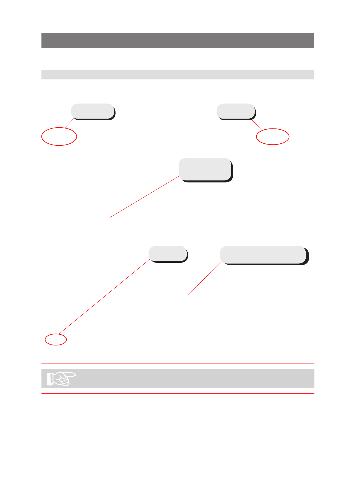
4.1 The Job Screen
This is the screen displayed when the machine starts up.
See
section 5
See
section 7
See
section 6
List of
existing jobs–
see section 5
Graphic shows machine
conguration
See section 5 for running an existing job directly from this screen.
Page 13
12
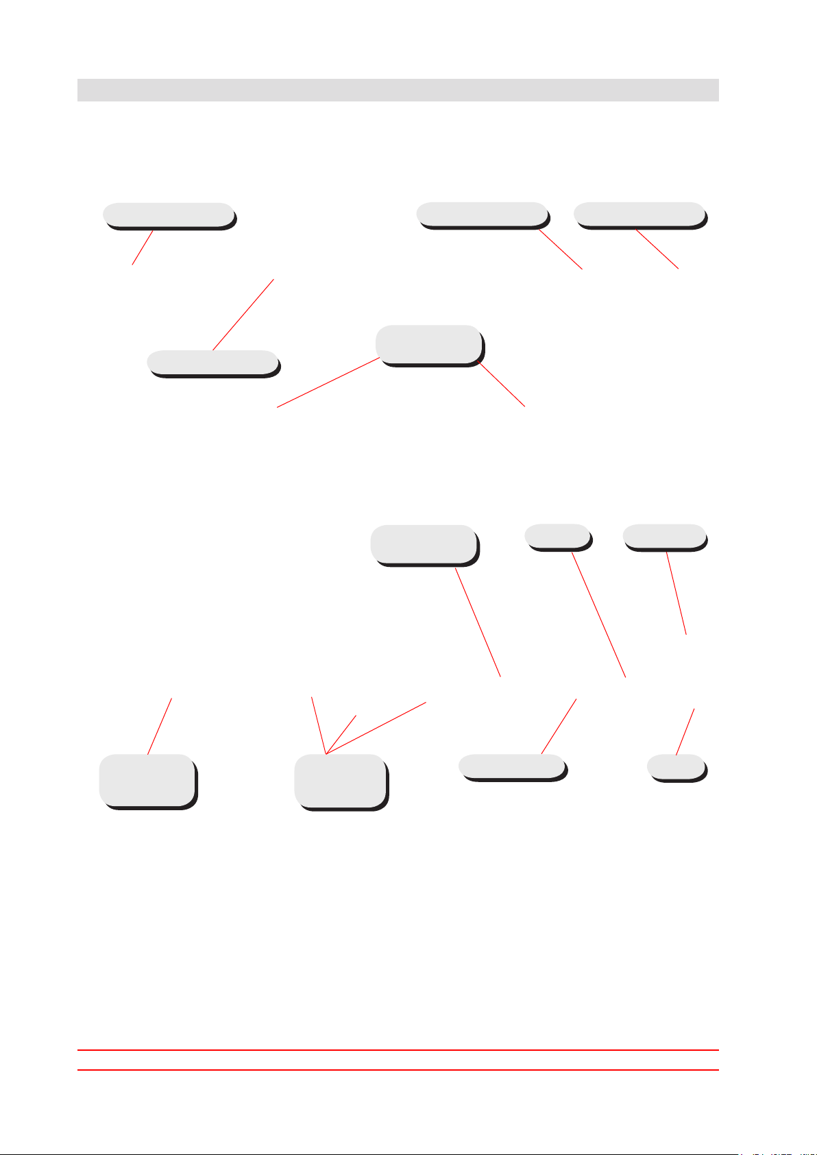
4.2 The Run Screen
4.2.1 The Run Screen displayed
This is the screen you will see after an existing job has been selected in the Job
Menu.
See section 4.1
See section 3
See section 6
Paper load
indicators
Zero the
counts etc.
Pause
Close IMOS*
Autoend
Speed
controls &
indicator
Count
& time
indicators
Single cycle
Run
* This button closes down the IMOS operating software - it does not switch the
machine off.
To change the current user or job, click on the buttons and you will be presented
with a list of all those that have been created, and allow you to select any one.
Note that to change to a different user will require the appropriate password to be
entered. To view and adjust the settings for the envelope and document inserters,
click on the relevant part of the machine graphic (see the following pages for details).
Page 14

13
4.2.2 To adjust the Envelope Inserter settings
Unit Fine Tuning
All ne adjustments apply only to the current job and will not
affect any other jobs.
Select the inserter icon on
the machine graphic in the
Run screen to display the
ne tuning screen. Select
Hardware Fine Tuning to
display further information.
You can change:
a: The width of the collate
pocket guides.
b: The overall width of the
insert ngers.
c: The time allowed for
the ap to seal before the
envelope is ejected.
d: Adjustment of the point
at which the wetter beam
drops to wet the ap. +ve
increases wetting in 1mm
steps (moves start point
towards insertion area).
e: Adjustment of the point at which the wetter beam lifts. +ve increases duration,
ie. a greater length of ap is wetted befor the beam is lifted.
f. Adjustment of the amount of envelope travel into the sealing rollers. +ve = fur-
ther forward, away from exit direction.
g. Adjustment of the envelope stop position for insertion. +ve = further forwards,
towards exit direction.
h. Adjustment of the amount of insertion of the insert pack into the env
= further forwards past the ap crease.
i. Adjustment of the amount of envelope foward tra
reversing to enter the sealing rollers. +ve = further forward into the output rollers,
towards the exit direction. Note: for high-window envelopes, this should be
set to 20 - 50mm +ve.
vel after ap wetting, before
elope. +ve
When all adjustments are complete, select the ‘Unit’ button for hopper settings, as described overleaf.
Page 15

14
Hopper Fine Tuning
From here you can adjust
hopper settings. Select the
envelope icon on the machine graphic in the Run
screen then Document
Fine Tuning to display
further information. You
can change:
a: Whether or not the envelope is sealed. Select ‘Off’ if, for example, later hand
insertion of an insert or any other item will be required.
b: The setting of the amount of envelope deskew required. Note a higher level will
slow the machine more.
Important: All ne adjustments apply only to the current job and will not
affect any other jobs.
Important: All ne adjustments apply only to the current job
and will not affect any other jobs
Page 16

15
4.2.3 To adjust the Document Unit settings
Unit Fine Tuning
The ne tuning options available will depend upon whether a
Versatile Feeder or Flex Folder is tted.
Select the document or insert icon on the machine graphic in the Run
screen to display the ne tuning screen.
Hopper Fine Tuning
From here you can adjust
hopper settings. You can
select:
a: Feed Always or not. If you
select Off, the unit is disused
until it is turned back on
again.
b: Whether doubles detection
is turned on or off. Turn off if
booklets or very thick inserts
are being fed. Note: refers only to optical detection - mechanical detection may also be tted.
c: Only for Reading units. Retrieve CIS Image - if selected, images of the label as seen
by the CIS reader will be displayed. The images will be of the nal 2 documents in the group
and can be useful for error checking by conrming that the whole label was read, for exam-
ple, or comparing the 2 images.
Important: All ne adjustments apply only to the current job
and will not affect any other jobs
Page 17

16
4.3 The Menu Screen
The Menu screen allows various functions to be selected. These functions are described in detail further in this document.
Page 18

17
5 Running an existing job
This section describes running an existing pre-programmed job. To create a new
job, see section 7.
If the IMOS operating software is not already running, it must be started using the
icon on the monitor screen. To access the PC to switch it on, open the cupboard
below the inserter head.
Before running a job, the paper hoppers must be loaded with stationery - see section 8 for details.
1 If the Job screen
is not already displayed,
press the Jobs button
at the top and select the
required job from the list
(use the scroll arrows if
needed).
2 Summary of se-
lected job is shown.
3 If you are happy
with your selection, press
Accept, otherwise, select
another job.
Page 19

18
4 Load the paper and
envelopes in the hoppers
indicated.
5 Press the Run but-
ton to begin operating.
See also section 4.2 for
a full description of the
controls.
Paper is normally loaded in the Tower face-up and feet-rst if non-
reading, face down and head-rst if reading. This may vary: see
also appendix A.
Page 20

19
6 Switching the user
6.1 How to switch the user
Each user has their own password and access rights, allocated by the Supervisor. To
switch user, the password must be known.
1 Press the Switch
User button in the Job
screen
2 Select the user
from the list. Use the
scroll arrows if necessary.
3 Press the Logon
button.
Page 21

20
4 Press the Login button.
6.2 User Access Rights
4 Enter the password
using either the keyboard
or the on-screen keypad.
The user has now
changed.
There are 4 levels of access rights that can be allocated to each user. These are
described below:
Rights Operator Expert
Operator
Change Jobs Y Y Y Y
Run Machine Y Y Y Y
Programme Jobs
with Wizard
Add items to
Libraries from
Wizard
Add Items to
Libraries from
Outside Wizard
Mechanical Fine
tuning
Document Fine
tuning
Enter Service Menu N N Y X
Enter Admin Menu N N X Y
Avoid PC shutdown
on IMOS Exit
N Y Y Y
N Y Y Y
N N Y Y
N N Y Y
N Y Y Y
N Y Y
Engineer Supervisor
Page 22

21
7 Creating a job
Creating a job consists of a number of steps:
Dening the Mailset (Envelope, document & enclosures)•
Dening the Fold Settings•
Setting required Output Options•
Saving the Job to a Jobname•
When dening the Document in the Mailset, OMR or Barcode denitions can be enabled if required.
Note that for an OMR of Barcode denition to be used it must rst have
been created - see section 7.3.
7.1 Creating the Job Settings
1 Press the Cre-
ate Job button in the Job
screen.
2 Press the Auto-
matic button.
You will now need to dene the mailset (envelope, documents and enclosures). This
is described on the following page.
Page 23

22
7.1.1 Dening the mailset
Selecting the envelope
3 Press the Select
button to choose an envelope from the available
library.
4 Select the required
envelope from the library
and press the OK button.
If there are no envelopes in the library, or if you wish to create a new
one, see section 7.3.
Page 24

23
5 You now have a
choice: carry on to select
a document, or further
dene the envelope usage, ie. sealing mode and
deskew.
The following assumes
you want to further dene
the envelope usage. When
you have nished you
will return to the screen
shown here.
Press the Settings button.
6 Select the required
Sealing mode (usually this
will be ‘Always on’).
Press the Edit advanced
button if you wish to
change the deskew setting.
Page 25

24
7 From here, you
can turn adjust the degree
of deskew, or turn it off if
you require. This might be
done to speed the ma-
chine up if, for example,
an envelope is unlikely to
skew, eg. a C5 or other
longer envelope.
The default deskew setting is ‘Low’.
Page 26

25
Selecting the document
8 Press the Select
button to choose a document from the available
library.
9 Select the required
document from the library
and press the OK button.
If there are no documents in the library, or if you wish to create a
new one, see section 7.4.
Page 27

26
10 You now have a
choice: carry on to select
enclosures, or further de-
ne the document usage,
eg. form count, cascading,
hand-feed etc.
The following assumes you
want to further dene the
document usage. When
you have nished you
will return to the screen
shown here.
Press the Settings button.
11 Adjust the forms
count if using mutliples,
whether or not cascading
is to be used, and whether
or not daily mail (handfeed) is to be used. Press
the OK button when done.
For further settings, press
the Edit Advanced button.
Page 28

27
12 If you wish to
choose an orientation other than the auto-selected
default, press Auto to enable the selector button.
If required adjust the
degree of deskew, or turn
it off if you require, for example if a document type
is found to feed reliably
without skewing.
Thickness doubles can
currently be checked opti-
cally only on a ex folder,
or turned off, if for exam-
ple, documents are substantially different from
the calibration document,
such as abnormally dark
with heavy printing.
Selecting ‘Auto’ allows the software to choose between optical and mechanical
checking if the document is moved to a versatile feeder tted with a mechanical
system.
Feed control mode is ‘Feed Always’ as default, but can be turned off to disable the
hopper. It can also e set to ‘Selective Feed’ for reading-enabled units. This works in
conjunction with ‘Item ID’ - see below.
Item ID allows you to dene an ID number for the document which accords with
the relevant Select mark in the OMR or Barcode label. This will then feed the document when that mark is read.
Sequence handling mode determines how sequence marks (if used) are handled
when a document set is broken up (for example, to change a job in the middle of a
document set). The mode must be det to ‘Full’ for the rst pass, and then changed
to ‘Mailset’ for the second pass after the job has been changed. The machine will
not then expect an unbroken sequence.
Page 29

28
Selecting the enclosure
13 If you are using
enclosures (inserts, BREs,
booklets etc.), press the
Select button.
14 Select the required
enclosure from the library
and press the OK button.
If there are no enclosures in the library, or if you wish to create a new
one, see section 7.5.
Page 30

29
15 You now have a
choice: carry on to select
further enclosures if required, remove the enclosure you have selected,
or further dene the enclosure usage, eg. form
count, cascading, handfold etc.
The following assumes you
want to further dene the
enclosure usage. When
you have nished you
will return to the screen
shown here.
Press the Settings button. Settings and Advanced Settings are same for en-
closures as for documents - see steps 12 & 13.
Paper is normally loaded in the Tower face-up and feet-rst if non-
reading, face down and head-rst if reading. This may vary: see
also orientation chart in section 8.3.
Page 31

30
16 If further enclo-
sures are required, press
the Add button and repeat
steps 13 to 18.
Repeat as required up to
the limit of available stations.
You now have a choice: to
proceed and move on to
Fold Settings, or to assign
the documents/enclosures
to specic hoppers.
The following assumes
you want to assign the
documents/enclosures to
specic hoppers. This will
override the hopper that
the software automatically
assigns.
If you do not want to assign the documents/enclosures to specic hoppers, press the Next button shown in the previous screen.
Otherwise, press the Document Placement button shown in the previous screen.
This will display a selector box:
17 Deselect ‘Auto’ to
enable the selector box.
Select the hopper that you
wish to assign the relevant
document to and press
the Ok button.
The hopper is now assigned to that document.
Page 32

31
The mailset is now dened, and the screen will show that this is ticked.
You will now dene the fold settings.
7.1.2 Dening the fold
18 The machine will
automatically select the
optimum fold type. If you
wish to change this, deselect ‘Auto’ and set the
required fold. Caution:
the machine may not
perform properly if you
change the fold type
wrongly.
If you wish to make adjustments to the fold
lengths, or just check
them, press the Adjust
fold button.
19 Make adjustments
as required and press the
OK button.
Page 33

32
20 If you wish to
make adjustments to the
collation mode or Max no.
of sheets folded together,
press the Edit advanced
settings button.
21 Choose whether to
collate leading edges of
documents as they feed
through the folder, then
folded together without
entering the accumulator, or to feed separately
into the accumulator before folding. Sheets are
fed singly by default, so
each sheet is folded and
inserted separately. Set
max number for folding
together. Groups bigger
than this will be split into
a) max number, followed
by b) remainder.
The maximum that can be fed into the accumulator defaults to 9, but can be up to
25. Note: This will depend upon the paper type.
Multi-envelope mode allows two separate jobs to be run in succession using the
same document set. If set to ‘Split Oversize’, this splits, folds and inserts as for
‘Max Fold’ described above. If set to ‘Divert Oversize’, all groups numbering greater
than the number set in ‘Divert/Split Threshold’ will be diverted to the divert tray,
and if set to ‘Divert Undersize’, the same will apply for groups below the threshold.
The machine is then stopped, the job is changed and the forms in the divert tray
are put back into the document set, and the new job is run.
‘Divert Action’ allows the option of the machine stopping automatically upon divert,
or to continue, allowing the operator to intervene.
When you have nished, fold settings are now complete and the screen will show
that this is ticked. You will now dene the output settings.
Page 34

33
7.1.3 Dening the output settings
22 Select whether
batch mode is to be used,
and the quantity. The
machine will then process
this number of cycles,
then stop. This will be
repeated until the machine
is stopped.
To dene the batch jog
steps, franker and MPPC
modes, press the Edit ad-
vanced settings button.
23 Select batch jog
steps and pause time. This
means that as each batch
is fed onto the conveyor,
it will move the specied
amount (the steps are
unitless), and pause for
the specied time.
The franking machine
mode and job are described on the following
page.
Page 35

34
Mode Options
• The franking conveyor will be run continuously while the in-
• Level 2/3 function – envelopes will not be franked.
• Level 2/3 function – envelopes will be franked
Not Used:• The franking conveyor will be driven like a standard con-
veyor, pulsed on each envelope.
Dumb:
serter is running.
Pass-through:
Franking Machine:
according to the program settings in the franking machine.
Job Options
Current Job:• Run the currently selected job ‘as-is’.
For most purposes, Mode will be set to ‘Franking Machine’ and Job
will be set to ’Current Job’.
Page 36

35
The output settings are now dened, and the screen will show that this is ticked.
You will now save the job.
7.1.4 Saving the job
24 Press the keyboard
icon to display the virtual
keyboard.
25 Enter a name for
the job using either the
virtual or physical keyboard.
Repeat steps 26 & 27 to
enter a brief description
for the job. This is the description that will appear
in the job list when the
machine is started.
26 Enter a name for
the job using either the
virtual or physical keyboard.
You have now successfully created a new job
and it will appear in the job list.
Page 37

36
7.2 Creating an envelope
In order for an envelope to appear in the envelope library, it must rst be created.
1 Begin creating a
job (see section 7.1)
2 At the point where
you need to select an envelope, press the Create
button.
3 Enter a name for
the envelope: press the
virtual keyboard icon and
enter the name using either the physical or virtual
keyboard.
Select an envelope type.
The default width and
height for that type will
then be shown. If you
want to adjust the size,
the type will change to
‘Custom’.
If you want to adjust the
envelope weight and ap
depth, press the Edit Advanced button.
Page 38

37
4 Adjust the weight
as required. Note that the
weight is the actual weight
of the envelope, not the
paper weight.
Press the Save button
when done.
The envelope will now be
available in the envelope
library under the name
you have given it.
The envelope is now fully dened and is available for use.
Page 39

38
7.3 Creating a document
In order for a document to appear in the document library, it must rst be created.
1 Begin creating a
job (see section 7.1).
2 At the point where
you need to select a document, press the Create
button.
3 Enter a name for
the document: press the
virtual keyboard icon and
enter the name using either the physical or virtual
keyboard.
Select a document type
and size. The default
width and height for that
type will then be shown.
If you want to adjust the
size, the type will change
to ‘Custom’.
If you want to make further adjustments, or se-
lect a reading denition,
press the Edit Advanced
button.
Page 40

39
4 Select the address
position. This defaults to
‘Top’; specify middle, bottom or none if required.
Specify whether the document is to be folded (eg. a
booklet iwould not be) and
its thickness and weight.
Note this is the actual
weight of the document,
not the paper weight.
The thickness is more applicable to booklets - if no
gure is specied, 80gsm
paper will be assumed.
If the document uses an OMR or barcode label, select a reading denition. Note:
this is obtained under licence as an option and must already exist on the
machine.
If the document does not use an OMR or barcode label, press the Save button, otherwise, proceed as follows.
5 Press the Region of Interest button to specify the position of the label.
6 Specify the posi-
tion of the label and press
the Save button when
done.
The document is now fully dened and is available for use.
Page 41

40
7.4 Creating an enclosure
In order for an enclosure to appear in the enclosure library, it must rst be created.
1 Begin creating a
job (see section 7.1).
2 At the point where
you need to select an enclosure, press the Create
button.
3 The procedure for
dening an enclosure is
the same as that for a
document, described in
section 7.3. It is the document type that you select
that determines whether it
appears in the document
or enclosure library.
See section 7.3 for the
remainder of the settings.
The enclosure is now fully dened and is available for use.
Page 42

41
8 Loading the paper hoppers
8.1 Loading the envelope hopper
Using the black knob,
adjust the side guide to
give 1-1.5mm clearance
each side of the
envelope.
Adjust the angle of the
backrest (see below) and
load the envelopes into
the hopper, aps forward
so that the lower edges
follow the contour of the
surface and down into
the pick-up roller. Move
the backrest forward
(see below) so the the
envelopes are fully
forward, but not tightly
packed.
Move the backrest forward by squeezing
the roller bar upwards to release the
rollers from the track.
Adjust the angle by slackening the knob
each side.
C4: Fully raised
DL/DL+: Fully lowered
Note:
If the envelopes feed erratically, try a
backrest angle in-between.
Page 43

42
8.2 Loading the versatile feeder hopper
1. Slacken the black knob
next to the side guides
(arrowed) and move the
guides to give 1-1.5mm
clearance each side of
the enclosure. Tighten
the knob.
2. Slacken the black
knob under the backrest
(arrowed) and move it
forwards to support the
enclosures as shown.
Ensure the enclosures are
directed down into the
feed rollers. Tighten the
knob.
Adjusting the separator
The separator prevents more than one enclosure being fed at a time.
To adjust the separator, turn the knob on
the back of the feed hopper.
Clockwise decreases the gap,
anti-clockwise increases it.
To set the separator gap, empty the
hopper, then slide an enclosure into the
gap and turn the knob until the separator
will just grip the enclosure as you
withdraw it.
To help you establish an initial setting,
there is a setting gauge on the separator
unit, visible after opening the feeder side
cover. See following page.
Page 44

43
1. Look into the aperture
shown and you will see
the setting gauge on the
side of the separator unit.
There is an 80gsm mark
as a starting point for
single sheets, and mm
settings underneath the 0
line for booklets etc. See
also section 8.5 ‘Daily
Post’.
2. Now adjust the gap as
previously described to
set it precisely.
For problem enclosures, the feed rollers can be changed to optional
alternatives; see section 9.3
See following page for load capacities of different stationery types.
Note: these are a guideline only - actual quantities may vary. The
label on the side quide will also provide an indication.
Page 45

44
1000 Sheets of 80gsm (20lbs
bond) or 400 BRE (DL)
130 x 2.5mm A5 Booklets
40 x 6mm A4 Booklets
500 x 0.5mm A5 Booklets
Page 46

45
8.3 Loading the ex folder hoppers
The ex folder may be tted with 500-sheet or 1000-sheet hoppers, or only a single
500-sheet hopper. The example shown has 2 x 500-sheet and 1 x 1000-sheet
hoppers.
1. On 500-sheet hoppers, slacken the black knob next to the side guides (arrowed)
and move the guides to give 1-1.5mm clearance each side.
On 1000-sheet hoppers,
slacken the black knob
above the hopper
(arrowed) and use
the tabs to move the
guides to give 1-1.5mm
clearance each side.
2. Tighten the knobs.
Paper orientation in the hoppers will depend upon the job
requirement - see the paper orientation charts on page 50.
Accumulator
If the ex folder is titted with an optional accumulator, the side guides must be
adjusted to suit the paper.
Raise the top of the accumulator so that
it locks in place and place a piece of
paper between the side guides.
Slacken the black knob next to the side
guides (arrowed) and move the guides
to give 1-1.5mm clearance each side.
Actuate the latch (arrowed) to lower the
accumulator top.
Page 47

46
Fold Plate 2
If fold-plate 2 is being used in the folding operation, it must be adjusted as shown
below (see chart on the following page for guide on fold plate usage).
1. Open the side cover on
the ex folder. Slacken
the fold plate knob
indicated and adjust it
according to the length
setting on the scale.
2. Tighten the knob.
3. Raise the two transport
assemblies so that they
latch in place, and lift the
roller assembly below
them.
4. Slide the indicated
latch away from you. This
will open fold plate 2 for
use (most applications do
not use fold plate 2).
5. Lower the roller and
transport assemblies,
ensuring they are latched
in place.
Page 48

47
Paper Orientations
Paper orientations for various applications are shown below.
European Sizes:
American Sizes:
Page 49

48
8.4 Paper Control Lever
The paper control lever is located in the collate area, and raises or lowers overguide
strips in the paper path. For normal running, the overguide strips should be lowered
to assist paper movement. However, in some cases (such as a single lightweight
sheet, or a thick pack with a lightweight prime document on top), it may assist
paper movement to raise the overguide strips.
1. Raise the perspex top cover to
obtain access to the collate area.
2. Move the lever rearwards (ie.
away from the envelope feeder)
for normal running.
3. Move the lever forwards (ie.
towards the envelope feeder) for
single sheets, lightweight prime
documents etc.
4. Lower the perspex top cover.
Page 50

49
8.5 Daily Mail (Handfeed)
Daily post allows a group of forms to be hand-fed, folded and inserted on a
Versatile Feeder. A group of forms up to a total of 6mm thick may be fed, but be
aware of the folding capacity of 8 forms of 80gsm (20lbs bond). The forms may be
stapled or not, as required (see below for stapling restrictions).
8.5.1 Stapling Restrictions
No staples in
area shown
8.5.2 Using Daily Mail
To use daily mail, dene a new mailset (as described in section 7.1.1) or edit the
document settings in an existing job.
Select Settings for the document and set ‘Daily Mail’ to Yes.
Save the document settings, then press Next until you reach the Save button to
save the job.
cont.
Page 51

50
8.5.3 Setting the Separator Gap (see also section 8.2 ‘Adjusting the Separator’).
Now set the separator gap to suit the daily mail. As a general guide, the gap should
be set to approx. 1mm greater than the pack or booklet thickness. If the document
is an 80gsm sheet, set the gap to 1mm.
If the thickness is unknown, proceed as follows:
Open the separator gap wide •
enough to allow the document
to pass through. Insert a
corner of the document
between the separator
wheels as shown - this avoids
snagging the grooves in the
tyres (particularly useful for
thin documents).
Close the separator gap until •
there is some friction on the
document, then rotate the
separator knob in reverse
direction 1 turn (this will give
clearance of 1mm).
When daily mail has been enabled as described, and the gap has been set, press
the Run button and feed the post into the hopper tray. The machine will wait
for 30 seconds after pressing the button - if you exceed this before inserting the
documents, press the button again.
To turn the function off, switch ‘Daily Mail’ back to No in Document Settings.
Page 52

51
9 Operator Maintenance
9.1 Cleaning the sensors
The optical sensors consist of two halves: emitter and receiver. These can become
obstructed due to paper dust and should periodicaly be cleaned using a non-
ammable airduster. Both halves must be cleaned.
This section shows where the sensors are located. For most sensors, an indicator
arrow is pierced showing you where the jet of the airduster should be directed. For
some sensors, the retaining bush is visible next to the lens: ensure you spray into
the lens, not the bush.
Insertion head
Sensors are retained with a bush next to the lens: where this is
visible, ensure that you spray into the lens (arrowed), not the bush.
Direct the airduster into the openings arrowed and spray liberally.
Open the perspex top
cover and raise the collate
clamshell (closest to the
envelope hopper) so that
it locks in place.
Picture shown is viewed
looking inside the collation
area towards the envelope
hopper.
Page 53

52
Picture is viewed looking
inside the collation area
away from the envelope
hopper.
Clean all sensors arrowed.
Lower the collate clamshell
and open the upper
conveyor (furthest from
the envelope hopper) so
that it locks in place.
Picture is viewed looking
inside the collation area
away from the envelope
hopper.
Insert the airduster nozzle
deep into the hole and
spray liberally. Note the
the upper sensor half is
not easy to see and is
mounted on a bar.
Lower the conveyor.
Lower the side cover and
raise the overguide inside
the closer cavity, latching
it in place.
Clean the sensors
arrowed.
Page 54

53
Picture is viewed looking
down on the envelope
hopper, at the front.
Clean the one-piece
reective sensor.
Page 55

54
Versatile Feeder
Open the feeder top
covers at the front, if the
feeder is the rst station.
If a subsequent station,
open the side cover and
approach from the side.
Picture is viewed looking
towards the front.
Clean the sensor arrowed.
The upper half is located
on a bracket above the
lower half.
Open the feeder top
covers at the front. Picture
is viewed from the side.
Clean the one-piece
reective sensor.
Page 56

55
Open the side cover and
push the lowermost lever
forward to lower the
conveyor.
Clean the sensor located
in the centre of the track
as shown, with the upper
half directly above it.
Page 57

56
Flex Folder
Open the folder top cover
and clean the sensors
indicated.
For the two sensors shown
side-by-side, direct the
nozzle of the airduster into
the gap at the front of the
them and spray liberally.
TRANSPORT
VERTICAL
TRANSPORT
ASSEMBLY
Open the side cover and
raise the two transport
assemblies so that they
latch.
Swing forward the vertical
transport assembly and
clean the sensor halves
indicated. Note: these
are not easy to see, and
a separate light such as a
torch may help.
When returning the
transport assemblies,
ensure that they latch
back into place properly.
Page 58

57
9.2 Clearing paper jams
If paper jams occur, the area affected will normally be shown in the error message
on the screen. Use one of the clearance methods described below to clear the
jammed paper.
Inserter head
Open the side cover on the operator side of the machine.
Versatile Feeder
Open the side cover on the versatile feeder.
Push forward the levers
indicated to open the
cavities and access the
jammed paper.
If the paper is not fully
visible, turn the blue
knobs to wind it into view.
Flex Folder
Open the side cover on the ex folder.
Base Unit
Using the release handles,
raise the 2 upper plattens
indicated and latch them
in place. Raise the roller
assembly below them to
access the jammed paper.
Note: the roller assembly
does not latch in place.
If the paper is not fully
visible, turn the blue
knobs to wind it into view.
Page 59

58
Tower Unit
Using the release handle,
swing open the vertical
platten indicated and latch
it in place. Raise the roller
assembly below them to
access the jammed paper.
Note: the roller assembly
does not latch in place.
If the paper is not fully
visible, turn the blue
knobs to wind it into view.
Page 60

59
9.3 Changing the feed tires
Certain documents (eg. glossy materials) may not not feed properly with the
standard feed rollers. Sets of optional feed tires are available to assist feeding.
These can be tted as follows.
Remove the 3 knobs
indicated and open the
side guides to their widest
extent.
Lift the feed bed out of the
chassis to access the feed
shafts beneath.
Slide the spring-loaded
collars inboard and lift the
feed shafts out of their
bearing hubs. The feed
tires can be pried off the
rollers and replaced with
alternative items.
When replacing the shafts,
ensure that the drive pins
are properly located in the
hubs.
Page 61

60
9.4 Adjusting the CIS reader
If a CIS reader is tted to a Flex Folder, it must be adjusted to align with the label,
as described below
On a 500-sheet hopper
pod, remove both feed
trays to access the CIS
reader as shown.
Slacken the knob and slide
the reader as required,
using the tabs. Tighten the
knob.
Note: the CIS reader
should be moved fully
left or right, depending
upon which side of the
paper the label is on.
On a 1000-sheet hopper
pod, remove all paper
from the machine and
operate a single cycle to
raise the tray.
From below the tray,
slacken the knob securing
the cover as shown, and
lift the cover out to access
the CIS reader.
Adjust the reader as
described above and
replace the cover.
Page 62

61
10 Technical Specication
Width Clearance
Envelope
Insert
Depth Clearance
10.1 Inserter head
Pack thickness Maximumpackthicknessisdenedastheinternal
dimensionofarigidopeningthatalledenvelopewillfall
throughunderitsownweight.
#10&DLEnvelopes: upto6mm(¼”)
C5/C4Envelopesandabove: upto6mm(¼”)
Pack clearance Theminimumclearancesrequiredbetweentheinsertsand
envelopesaredependentoninsertpackthickness.
Clearanceisthetotalclearanceandisdenedasthe
differencebetweenthelargestoveralldimensionsofthe
packandtheinternaldimensionsoftheenvelope(see
below).Therequiredclearancesaresummarisedas
follows:
Pack<3mm:Depth6mm(¼”)Width16mm(5/8”)
Pack>3mm<6mm:Depth12mm(½”)Width19mm(¾”)
Cycling speed Upto4800envelopesperhour(basedon1xA4folded
sheetintoaC5/C65orDLor#10(114mmx229mm)
envelope).
Upto3900envelopesperhour(basedon1xA4folded
sheetwith1xenclosureintoaC5/C6orDLor#10
(114mmx229mm)envelope).
Speedsforotherconditionsavailableonrequest.
Page 63

62
Monthly volume Up to 200,000 lled envelopes per month.
C5 or below - up to 800 of 90gsm (20lbs bond)
Envelope
C4 (at type) - up to 100gsm (28lbs bond)
Hopper
capacity
Envelope weight Minimum: C5 or below - 70gsm (18lbs bond)
Minimum: Above C5 - 90gsm (24lbs bond)
Maximum: 110gsm (28lbs bond)
General
envelope
requirements
• Envelope to be good quality machine-ll type.
Dimensions and quality to be consistent across
manufactured batches.
•
Side seams must be securely glued to the top of the
seam.
Flap crease must be pre-scored to enable the
•
envelope ap to open at.
no glue seepage must be evident on interior or •
exterior of envelope.
cont.
Page 64

63
Envelope details
Horizontal portion of throat
Max. = Envelope Width - 75mm(3")
Flap Shoulder Angle
Min.70mm (2
3
4
")
Minimum open
throat area
50°Min. 90°Max.
Min.
(
13
32
")
10mm
Throat angle
5°Min. 20°Max.
(
13
32
")
Min. 10mm
Max. = Envelope Width - 75mm(3")
Envelope Width Max. 330mm(13") Min. 225.5mm(8 7/8")
Min.70mm (2
3
4
")
Horizontal portion of throat
Flap Shoulder Angle
Body Depth
Max. 254mm(10")
Min. 98.5mm(3 7/8")
Minimum open
throat area
Min.
50°Min. 90°Max.
(
13
32
")
10mm
Throat angle
5°Min. 20°Max.
Min. 10mm
(
13
32
")
Flap Length
Max. 65mm (2½")
Min. 32mm (1
1
4
")
Side Seam style envelope
Commercial style envelope
Body Depth
Max. 254mm(10")
Min. 98.5mm(3 7/8 ")
Flap Length
Max. 65mm (2½")
Min. 32mm (1
1
4
")
Min. 10mm (
13
32
")
Max. 25mm (1")
Throat Depth
Envelope Width Max. 330mm(13") Min. 225.5mm(8 7/8")
Throat Depth
Max. 25mm (1")
Min. 10mm (
13
32
")
Page 65

64
Glue area
The bottom flap of the envelope
should be in-line or below the top of
the seam shoulders
Good example
Top edge of window to be flat
and free from puckering
Bad example - Out of
Specification
Windows to be securely affixed to
within 1.5mm (
1
16
") of top and side
edges.
Position of internal side seams to
give a minimum of 5mm (
3
16
")
clearance or overlap to the edge of
any insert
20mm minimum
14mm minimum to edge
of address carrier
Flap crease to be scored sufficiently to prevent distortion of envelope
between window and flap crease when closing and sealing.
Window width to be less than
40% of envelope width.
Page 66

65
Maximum distortion allowable on a
twisted envelope to be 10mm
(
3
8
") when envelope measured
sitting flat on a table
Built-in wetter tank, automatically pump-fed by 10-litre
Envelope
sealing uid
wetter container located in stand. Optional low-level oat
switch available.
Page 67

66
10.2 Flex tower
Paper Size Minimim width: 148mm (5¾”)
Maximum width: 305mm (12”)
Minimum length: 93mm (3 ⅝”)
Maximum length: 406mm (16”)
Paper weight Minimum 70gsm (18lbs bond)
Maximum 120gsm (32lbs bond)
Folding capacity C, Z or V-fold: 8 sheets 80gsm (18lbs bond)*
Double-forward fold: 4 sheets 80gsm (18lbs bond)*
* Multiple folded sets dependent upon pack thickness.
Hopper capacity Tower can be ordered with 1 or 2 pods, each tted with 1
or 2 hoppers as follows:
2 x 500 sheets of 80gsm (18lbs bond)
1 x 1000 sheets of 80gsm (18lbs bond)
Examples shown above are for illustration only. Other
congurations are available.
cont.
Page 68

67
Daily mail Up to 8 sheets of 80gsm (20lbs bond) for C, Z or V fold,
up to 4 sheets of 80gsm (20lbs bond) for double forward
fold, up tp 25 sheets of 80gsm (20lbs bond) unfolded.
May be stapled or not. Max. thickness of staple 3mm.
Allowable staple positions are shown below.
No staples in
area shown
Page 69

68
10.3 Versatile feeder
Enclosure Size Minimim width: 148mm (5¾”)
Maximum width: 305mm (12”)
Minimum length: 93mm (3 ⅝”)
Maximum length: 216mm (8½”)
Enclosure weight Minimum 80gsm (20lbs bond)
Maximum 6mm (¼”) thickness
Hopper capacity 1000 sheets of A4 80gsm (18lbs bond)
500 sheets of A4 Z-folded 80gsm (18lbs bond)
250 x 2.4mm booklets
400 x C5 envelopes
270 x DL envelopes
Note: quantities shown above are maxima. Depending
upon other conditions, actual quantities may be lower
than those shown.
Requirements
Some enclosures may require special tyres.
Daily mail Up to 25 sheets of 80gsm (20lbs bond) unfolded. May be
Enclosures must be exible enough to suit path
constraints.
stapled or not. Max. thickness of staple 3mm. Allowable
staple positions are shown below.
No staples in
area shown
Page 70

69
10.4 Mechanical & Electrical
Noise level:
xxdbA (3 x Versatile feeders, 1 x Flex tower, measured at 1.6m
height, 1m from nearest cover).
Heat Output (BTU/Hour):
Rated current x rated volts x 3.412 (eg. 2464 BTU/Hour for typical
conguration of 3 x versa feeders + ex tower folder).
Heat Output (Watts):
Rated current x rated volts (eg. 722W for typical conguration of 3 x
Versatile feeders + Flex tower folder).
Electrical:
230VAC 115VAC
Frequency 50Hz 60Hz
Input Current Head: 0.85A Head: 1.6A
Versa Feeder: 0.58A Versa Feeder: 1A
CIS Feeder: 0.58A CIS Feeder: 1A
Flex Tower: 0.55A Flex Tower: 1.4A
Fuse Rating T6.3A T10A
(Insert Head)
Weights:
Unpackaged Packaged
Inserter Head 97Kg 122Kg
Versatile Feeder 60Kg TBA
Flex Tower* 120Kg TBA
Conveyor 20Kg TBA
Stand Units 35Kg ea. TBA
* 2-pod version (each with 2 x 500 sheet-trays), and including accu-
mulator with diverter tray.
Sizes:
Inserter Head 1150L 550W 600H
Versatile Feeder 700L 550W 800H
Flex Folder* 1000L 550W 900H
* Fitted with 4 x 500-sheet trays and accumulator
Page 71

70
11 Glossary of terms
Term Description
Address carrier The address carrier is the document that carries the address of
the person for who the mail set is meant. The address carrier
can consist of one or more sheets, from which at least the rst
sheet must contain the address. The address must remain visible
while enclosures are added and the document set is folded. The
fold type and selected envelope must ensure that the address
is visible behind the window in the envelope. For personalized
mailings there is always an address carrier present as long as
envelope printing is not supported. Normally there is one address
carrier.
Address
position
Automatic The feature of an inserting system to automatically determine its
job settings by measuring the sizes of documents and envelope.
From all feeders that are loaded one sheet will be taken. Based
on the maximum document length (which is also the length of
the document set) and the length of the envelope the fold type is
determined.
Automatic job A job that is created with the Automatic job functionality.
Barcode
Reading (BCR)
Business Reply
Envelope (BRE)
Cascading See Feeder linking.
C-fold See Letter fold.
Daily Post Capability of an inserting system to manually insert mail sets one
Deskew A system of straightening a skewed document or enclosure
Document A document is one of the components of a mail set. A document
Barcode Reading is intended for reading and interpreting printed
barcodes. The codes give information to the inserting system
about how to build-up and handle a set.
Envelope included in outgoing mail sets for addressee response
purposes.
by one into the system, which are then inserted into an envelope.
Optionally, depending on settings, additional enclosures can be
added and the mail set can be folded. This function is intended
for small amounts of mail that each can have a different build-up.
by driving it into a set of drive rollers that have been briey
stopped. This removes the skew, and after a set period of time,
the rollers restart. Deskew slows the machine down and can be
disabled or adjusted for amount of deskew for forms that are not
prone to skewing.
can consist of one or more sheets. Documents can be divided
into address carriers and enclosures. For personalized mailings
there is always one address carrier and an optional number of
enclosures.
Position of the address on the address carrier,
measured from the upper left corner. The address
position consists of a horizontal x coordinate, a
vertical y coordinate, a horizontal width w and a
vertical height h.
Page 72

71
Term Description
Document set The document set is the physical collection of address carrier and
enclosure(s) that is under production in the inserting system.
The document set is completed during production and is to be
inserted into the envelope. The number of enclosures can range
from 0 to the limit imposed by the number of available feeders,
whilst observing the overall pack thickness. Once the document
set has been inserted into an envelope it is called mail set.
Double
Document
Detection
Double parallel
fold
Double Document Detection is the sensor that measures the
thickness of a sheet to check if the inserting system does not
accidentally take more sheets than intended. DD sensors exist
on feeders (double sheet detection). Currently DD detection
on Neopost inserting systems perform relative measurements,
which means that they need a cycle to ‘learn' the thickness of
a sheet. Also the length of the document is measured so partly
overlapping sheets will be detected.
The double parallel fold is a type of fold where the document is
rst folded halfway and the resulting folded set is again folded
halfway. This fold is illustrated in the picture below. The position
of both folds is adjustable.
Envelope The envelope is the packaging of a mail set. Window envelopes
are envelopes that have a transparent section through which the
address on the address carrier can be read. Besides the normal
top closing window envelopes there are also bottom closing
envelopes.
Face down Situation in which the front of a sheet is facing downwards when
placed in a document feeder.
Face down
leading
Face down
trailing
Face up Situation in which the front of a sheet is facing upwards when
Face up leading Situation in which the front of a sheet is facing upwards and the
Face up trailing Situation in which the front of a sheet is facing upwards and
Feeder A feeder is a module for the input of documents to the inserting
Situation in which the front of a sheet is facing downwards
and the top of the sheet is closest to the separation unit in a
document feeder, ie. the front end of the tray.
Situation in which the front of a sheet is facing downwards and
the bottom of the sheet is closest to the separation unit in a
document feeder, ie. the front end of the tray.
placed in a document feeder.
top of the sheet is closest to the separation unit in a document
feeder, ie. the front end of the tray.
the bottom of the sheet is closest to the separation unit in a
document feeder, ie. the front end of the tray.
system. The feeder separates documents sheet by sheet from the
stack of documents in the feeder tray.
Page 73

72
Term Description
Feeder linking
(Cascading)
Feeder tray Part of the feeder that contains the stack of documents or
Flexcode OMR An OMR code for which the meaning of the OMR marks can be
FlexFeed® The exFeed® is the feeding part of the system.
High Capacity
Feeder
High Capacity
Vertical Stacker
Insert To insert is the action of inserting a document set into an
Inserter An inserter is the module where the document set is inserted into
Inserting
system
Insert‘n
Frank™
(mailing
system)
Job A job is an actually produced collection of mail sets based on
Job counter The counter that registers the number of mail sets that is
Letter fold
(also known as
C-fold)
Linking See Cascade.
+LFDSIHHGHU Feeder with high capacity feeder tray.
Multiples The feature of an inserting system in which more than one sheet
OMR Optical Mark Recognition (see further table entry).
OMR code
denition
Operator The person operating an inserting system.
The ability to load two feeders with the same document type
where the inserting system automatically switches to a second
feeder when the rst feeder is empty and vice versa. In the mean
time the rst feeder can be relled, so the inserting system can
keep running without having to stop for relling the feeders.
envelopes.
programmed in a dedicated way for a specic customer. This is
normally used to support the OMR codes from other suppliers.
Feeder that has a capacity up to 1000 sheets (on a Tower unit).
Optional stacker that is mounted on the exit of the system, to
stack lled envelopes.
•
envelope.
For native English speaking customers an insert is also a short •
document, not to be folded, usually an enclosure.
the envelope, the envelope is closed and if necessary sealed.
The system of all the modules that cooperate to perform the
inserting function (accumulate document set, fold and insert) and
have a single point of control.
Interface for the Neopost franking system.
a certain job denition at a certain point in time for a specic
purpose. It consists of:
•
The job denition used for the production
Information about the batch size•
produced as part of a specic job.
Fold type in which a document set is folded twice in which the
folded aps are on top of each other. This fold is illustrated
below. The position of both folds is adjustable.
is taken from a feeder.
Standard 1-track OMR code denition. Species the amount
of reading marks used and the functionality linked to each of
them (how each should be interpreted). A denition is a licenced
option.
Page 74

73
Term Description
Optical Mark
Recognition
(OMR)
Output
Conveyor
Pod The feed hopper unit tted to a Tower. A Tower is available with
Reading error Condition in which the system could not reliably read or interpret
Reading marks Marks added to documents containing nishing instructions that
Receiving tray Fitted at the output for lled envelopes to be ejected into. Basic
Remote
diagnostics
Service
engineer
Single fold A single fold implies the document set is folded once. The fold
Optical Mark Recognition is intended for reading and interpreting
printed codes. These codes are one or more black marks which
are read from a document. These marks give information to the
inserting system about how to build-up and handle a set.
Fitted at the output for lled envelopes to be ejected onto. Higher
capacity alternative to a receiving tray. 2 lengths are available.
either 1 or 2 pods, each one consisting of either 2 x 500-sheet
trays or 1 x 1000-sheet tray.
the OMR reading marks or barcode from a sheet.
can be identied by an reading head and interpreted according to
the used OMR code denition.
alternative to an Output Conveyor.
The feature that makes it is possible to analyze a problem on an
inserting system from a remote location.
Technical engineer whose task it is to resolve problems with
systems in the eld. Besides dealing with problems, service
engineers are also responsible for preventive maintenance.
position is adjustable. This fold is illustrated below:
Stop counter Counter which sets the amount of envelopes to be lled. After
lling this amount of envelopes the system will stop.
Supervisor Person who is responsible for the technical state of the system.
Normally a supervisor has access to programming functions,
which are restricted for standard users.
Test run A test run is intended to validate the settings of the inserting
system:
•
Inspect and adjust the stop position of the envelope.
Check the fold settings for one set.•
Check whether the address is correctly positioned behind the •
envelope window.
Tray (or
hopper)
Vertical
transport
Contains a stack of paper for a printer or inserter. This paper is
supplied to the system for further processing.
The vertical transport section between hoppers and folder/
collator below .
Page 75

74
Term Description
Z-fold (also
known as
zigzag fold)
A Z-fold means that a document is folded twice in such a
way that each folded ap is on a different size of the folded
document, resulting in a Z-shape. This fold is illustrated below.
The position of both folds is adjustable.
Page 76

Page intentionally
left blank
76
 Loading...