

Page 1

7102 Series / 7102XT Series
High-Capacity Modular Inserter Systems
11/2014
OPERATOR MANUAL
Page 2

Table of Contents
Introduction ...................................................................................................11
Introduction.......................................................................................................1
Safety notes ...................................................................................................32
Safety notes.....................................................................................................3
Description of machine ................................................................................73
Description of operation...................................................................................7
Identification of parts........................................................................................8
Control Panel ...............................................................................................104
The Job Screen..............................................................................................10
The Run Screen.............................................................................................11
The Menu Screen...........................................................................................20
Running an existing job .............................................................................215
Running an existing job..................................................................................21
Switching the user ......................................................................................236
How to switch the user...................................................................................23
User Access Rights........................................................................................24
Creating a job ..............................................................................................267
Creating a job.................................................................................................26
Creating the Job Settings...............................................................................26
Creating an envelope.....................................................................................45
Creating a document......................................................................................47
Creating an enclosure....................................................................................50
Loading the paper hoppers ........................................................................518
Loading the envelope hopper.........................................................................51
Loading the feeder hopper.............................................................................54
Loading the tower folder hoppers...................................................................56
Page 3

Daily Mail (Tower Folder)................................................................................66
Adjusting the catch tray..................................................................................69
Operator Maintenance ................................................................................709
Cleaning the sensors......................................................................................70
Clearing paper jams.......................................................................................78
Technical Specification ..............................................................................8110
Inserter head..................................................................................................81
Tower Folder...................................................................................................84
Insert Feeder..................................................................................................86
Feeder Folder.................................................................................................87
Mechanical & Electrical..................................................................................88
Glossary of terms .......................................................................................9111
Glossary of terms...........................................................................................91
Page 4
Introduction1
Introduction
With this inserter you have an advanced, medium-volume folding and inserting machine.
Its modular construction allows multiple feed units to be fitted, with a maximum of 17 feed
units for 7102XT and 9 feed units for 7102. Its sophisticated software control optimises
the order and flow of documents for collating at the insert head before insertion into the
envelope. All fold and adjustments take place automatically according to the requirements
programmed in by the operator.
In order to ensure the long usage of this machine and its components, and above all the
safe use of the machine, you must read and adhere to the operating instructions and safety
notes. Always be aware of all warnings and notes that are mounted or noted on the machine
itself.
All persons entrusted with the handling of this machine must also be familiar with the
operating manual.
Save this handbook carefully, so that the information it contains may be available at all
times.
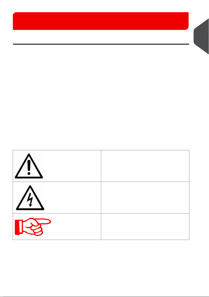
Pictograms
General Warnings
1
English
Warning of danger from electricity or electrical shock
Information / Note indicating important information regarding the handling of the machine.
1
Page 5

Notes on the use of this handbook
This document contains all general information and explanatory text necessary in order to
1
be able to carry out the operation of the machine.
When some action is expected from the operator, this will always be explicitly stated, and
where relevant, accompanied by an illustration or graphic.
Always read through each step, so that you will obtain all of the necessary information. Do
English
not anticipate what you believe will follow in the handbook: It will prevent you from making
mistakes!
Chronology and Reference
This handbook is structured chronologically, and therefore ordered sequentially for the
operationally ready machine. It assumes that the machine has been installed in the correct
environment by an Authorised Service Engineer and that the operator or his or her supervisor
has had a degree of operator training.
When you are unfamiliar with the machine, it is best to read through the handbook from
beginning to end. You will be guided step by step, and in this way you can easily and quickly
have the machine in operation.
If you are already familiar with the machine, it will make things easy if you use this handbook
as a reference work.
2
Page 6

Safety notes2
Safety notes
For your own safety and the operating safety of the machine, read the following notes
carefully before starting your machine. Always be aware of all warnings and notes that are
mounted or noted on the machine itself. Save this handbook carefully, so that the information
it contains may be available at all times.
The machine is of advanced construction and reliable in operation. Nevertheless, the device
does present hazards when operated by untrained personnel. The same applies to use
that is inappropriate and not in keeping with its intended purpose.
In not adhering to this handbook, there is the danger of
• An electrical shock.
• Injuries from the intake at the rotating rollers.
• Damage to the machine.
To stop the machine in an emergency, open any cover.
General safety notes
Please, read these notes with care.
Save these instructions for later use.
All notes and warnings found on the machine are to be followed.
2
English
Installing the machine
The machine must be installed only by an Authorised Service
Engineer.
3
Page 7

A safe, level position is necessary, when installing the machine, with sufficient space all
round to operate it. The machine is to be protected from moisture. If moving the machine,
ensure that the castor brakes are off, and push on the stand, not the machine.
Ensure there is at least 1 metre of free space between the operator side of the machine
and a wall or barrier. To provide access to the mains switch, the opposite side of the machine
must be at least 150mm from a wall or barrier. Do not place surrounding furniture or other
objects where your path may be obstructed.
2
Electrical danger
The machine may only be connected to a voltage of 230V/50Hz or 115V/60 Hz,depending
upon model.
English
The mains plug may only be connected with a socket having an installed protective contact!
The protective effect will be compromised by the use of an extension line without a protective
grounding conductor. All interruptions of the protective grounding conductor, within or
outside of the machine, are prohibited. The device is double pole fused! When fuse failure
occurs, electrical machine parts can still carry voltage. When making the connection to the
mains power, be aware of the connection values on the nameplate. Inspect the voltage
setting on the device’s power input module. Run the supply lines in such a way, that no-one
may trip over them. Do not place any objects upon the supply line. When the machine is
not in use over a long period of time, it should be disconnected from the power supply. In
this way, damage would be prevented in the event of excess voltage. Protect the device
from moisture. When moisture enters the machine, there is the danger of electrical shock.
Never open the machine except the top cover. For reasons of electrical safety, the machine
may only be opened by authorized Service Agents.
Operating safety
Never reach into the machine when it is running! This could only occur if a safety interlock
were to fail.
The danger of injuries exists, through pulling in and crushing on the rotating rollers. In
addition, keep long hair and parts of loose clothing far from the machine in operation. If a
safety interlock fails, your Service Agent must be contacted immediately!
In order to prevent damage to the machine, only factory authorized accessory parts should
be used.
Cleaning the machine
Prior to cleaning the exterior of the machine, it should be disconnected from the power
supply. When cleaning the machine, do not use liquid or spray cleaners, but only a cloth
dampened with water.
Cleaning sensors
When cleaning sensors use only non-flammable airdusters.
Other types may use flammable propellants, which could result in fire or explosion.
Allow machine to be checked by the Service Technician
In the following cases, the mains plug must be unplugged and the device left for the
authorized Service Technician:
• When the mains cable or plug is worn or damaged.
• When water or other liquid has entered the device.
• When the device does not function properly, in spite of following the instructions
provided.
• When the device has fallen down or the housing is damaged.
• When there are noticeable differences in the normal operation of the machine.
4
Page 8

Spare Parts
When repair work is carried out, only original spare parts or spare parts corresponding to
the original parts may be used.
Repairs
Do not disassemble the machine any further than is described in this handbook. Other than
the top cover, the opening of the machine by unauthorized personnel is not permitted.
Repairs may only be carried out by an authorized Service Technician.
Modification is not permitted:
For safety reasons, your own reworking and modifications are not permitted.
Please contact your Service Techncian, for all questions relating to
service and repair. In this way, you ensure the operational safety
of your machine.
End of life
The objectives of the European Community’s environment policy are, in particular, to
preserve, protect and improve the quality of the environment, protect human health and
utilise natural resources prudently and rationally. That policy is based on the precautionary
principle and principles that preventive action should be taken, that environmental damage
should as a priority be rectified at source.
Separate collection of waste is the precondition to ensure reuse and recycling of waste
that is generated at the disposal of electrical or electronic equipment and is necessary to
achieve the chosen level of protection of human health and the environment in the European
Community.
More particularly, certain materials and components of waste electrical and electronic
equipment needs selective treatment as their injudicious handling or disposing of on or into
land, water or air would represent a major threat to the environment and human health.
In order to facilitate collection and treatment separated from normal domestic waste,
electrical and electronic equipment is marked with the following logo:
2
English
Not only are you by law not allowed to dispose of the waste equipment via other
wastestreams, but we encourage you to actively contribute to the success of such collection
and to the common good and better quality of life of present and future generations.
For more information on the correct disposal of this product please contact your local dealer.
5
Page 9

FCC Compliance
This equipment has been tested and found to comply with the limits
for a Class B digital device, pursuant to Part 15 of the FCC Rules.
2
This equipment generates, uses and can radiate radio frequency energy and, if not installed
English
and used in accordance with the instructions, may cause harmful interference to radio
communications. However there is no guarantee that interference will not occur in a particular
installation.
If this equipment does cause harmful interference to radio or television reception, which
can be determined by turning the equipment off and on, the user is encouraged to try to
correct the interference by one or more of the following measures:
• Increase the separation between the equipment and receiver.
• Connect the equipment into an outlet on a circuit different from that to which the
receiver is connected.
• Consult the Technical Support department for help.
These limits are designed to provide reasonable protection against
harmful interference in a residential installation.
Changes or modifications not expressly approved by the party
responsible for compliance could void the user’s authority to operate
the equipment.
6
Page 10

Description of machine3
Description of operation
The function of the machine is to fold forms to ‘C’, ‘Z’, ‘V’ or double forward fold, either
singly, in fixed multiples or in varying groups. Enclosures such as inserts, BR envelopes
etc. may be added. Folded forms and enclosures are collated in the collation area in the
inserter head before insertion into the envelope. Forms may be inserted without sealing
the envelope for subsequent checking or hand insertion.
There is a batch processing facility, allowing a preset number of cycles to be completed
before the machine automatically stops.
The machine is OMR/Barcode/2D compatible for use with a reading feeder or tower folder,
allowing a group of forms to be collated on the track prior to folding. A number of barcode
symbologies may be read.
The machine consists of a number of modules, depending upon the build ordered - these
modules are briefly described below:
• Inserter head - Collates all documents in a pocket before insertion, feeds the
envelope, inserts the pack and seals the flap.
• Feeder - Feeds shortform inserts (cards, BR envelopes, booklets etc.) onto the track
for subsequent insertion. Available with single or twin feed hoppers. An
OMR/Barcode/2D version is also available.
• Feeder Folder - Track mounted folder for folding document inserts. Fitted with a
2-plate folder mechanism for C, Z or V folds. Single hopper only.
• Tower Folder - Mounts at the end of the machine. Folds documents either separately
or in groups, using an accumulator if required. Fitted with either a 1 x 1000, 3 x 500
or 1 x 1000 plus 1 x 500 sheet trays. Uses a 3-plate folding mechanism. An
OMR/Barcode version is also available (top or bottom read).
The machine is equipped with PC controlled operating software from where jobs can be
programmed and run. The number of jobs that can be programmed is limited only by the
capacity of the PC. Input is via touchscreen monitor.
A daily mail function can be used as an optional feature on a flex folder or versatile feeder.
This allows groups of documents, stapled or loose, to be hand-fed; they will then be folded
and inserted into an envelope (flex folder only). If other hoppers are loaded, further forms
can be collated.
No manual setting of the fold plates or envelope closer is required, these being adjusted
automatically according to the settings in the selected program.
The envelope output conveyor replace a standard receiving tray, and can be installed
in two possible orientations, straight-on or at a 90-degree angle to the system.
3
English
7
Page 11
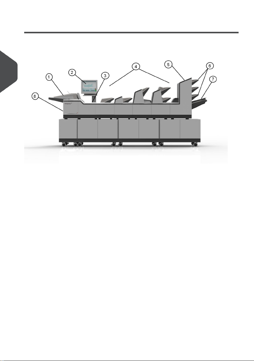
Identification of parts
The main parts of the machine are shown below.
3
English
8
Page 12

1. Envelope feeder
Holds up to RU800 envelopes (;7). Fitted with aVHQVLQJ conveyor
that operates ondemand to move the envelope stack forward.
2. Touch-sensitive monitor
Runs the IMOS operating software and responds to button pushes.
3. Collation and insertion area
Folded forms, either singly or in groups, are collated here into one pack, along with
enclosures. The pack in then inserted into the envelope.
4. Feeders/Folders
These are track mounted units, with an end-station variant also available. Up to 17
feed trays for a ;7 for a may be fitted.
The feeder (single or twin) feeds enclosures such as inserts, flyers, BREs etc. The
hopper holds up to 1000 inserts. A reading variant for OMR/ BCR/2D is
also available, as is a feeder folder for long documents.
5. Tower Folder
This is a folder unit and is only available as an end module. It can be fitted to the
insertion head on its own, or in conjunction with feeders. It is fitted with various options
of feedWUD\V and an accumulator (see following page).
6. Feed Trays
Fitted to the Tower Folder. 3 options available: 3 x 500-Tray, 1 x 500 with 1 x
1000-Trays & 1 x00-Tray; all variants can be mark reading as an option.
7. Accumulator
$WWDFKHG to the Flex Tower and allows groups of forms to be collated together before
folding as a group.,W is also fitted with a diverter tray
8. Closer/Eject Area
This is where the envelope flap is closed and sealed before ejected the filled envelope
into a receiving tray or onto a conveyor.
3
English
Items 1, 2, 3 & 8 are all part of the Insertion Head Unit.
9
Page 13
Control Panel4
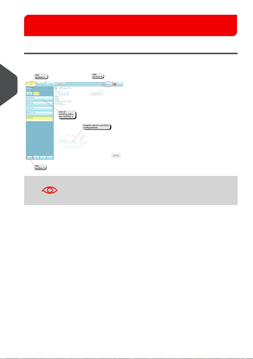
The Job Screen
This is the screen displayed when the machine starts up.
4
English
See Running an Existing Job on page 21 for running an existing
job directly from this screen.
10
Page 14
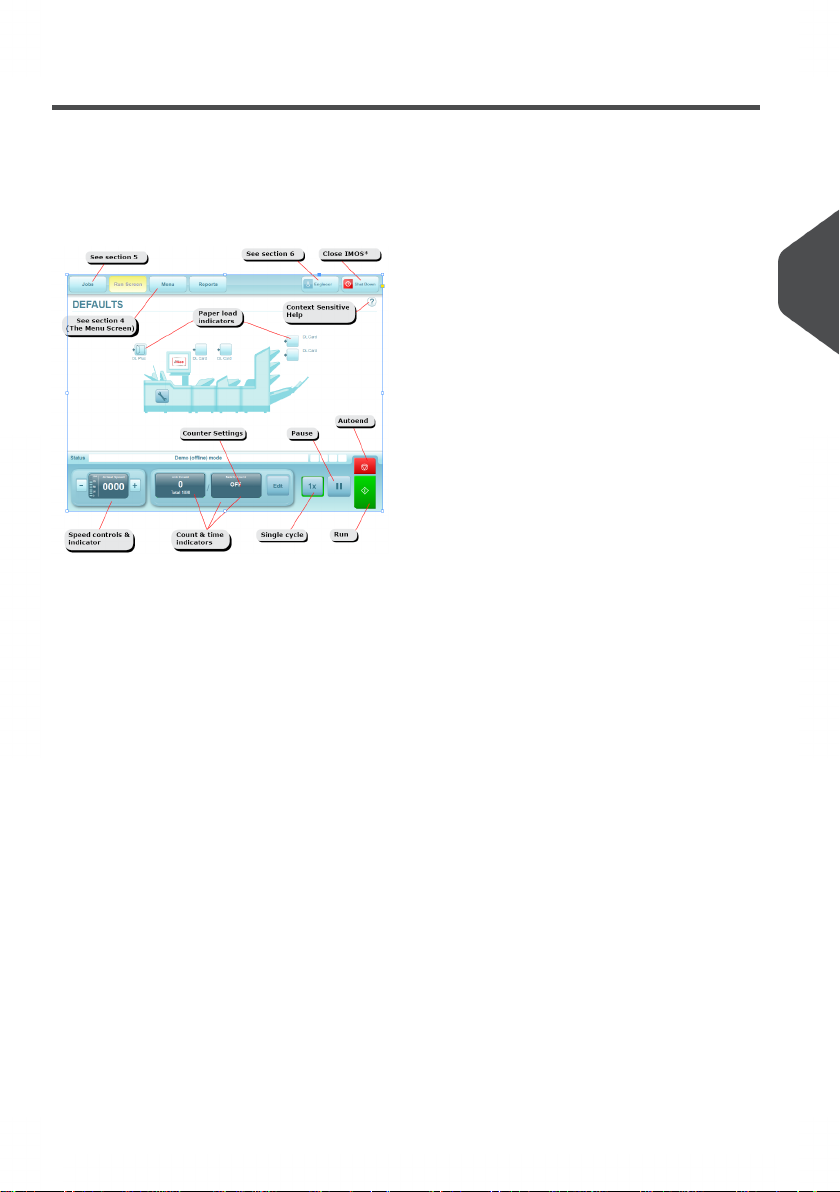
The Run Screen
The Run Screen displayed
This is the screen you will see after an existing job has been selected in the Job Menu.
* This button closes down the IMOS operating software - it does not switch the machine
off.
To change the current user or job, click on the buttons and you will be presented with a list
of all those that have been created, and allow you to select any one. Note that to change
to a different user will require the appropriate password to be entered. To view and adjust
the settings for the envelope and document inserters, click on the relevant part of the
machine graphic (see the following pages for details).
Important: you must be logged in as Supervisor to change the current user or job.
4
English
11
Page 15
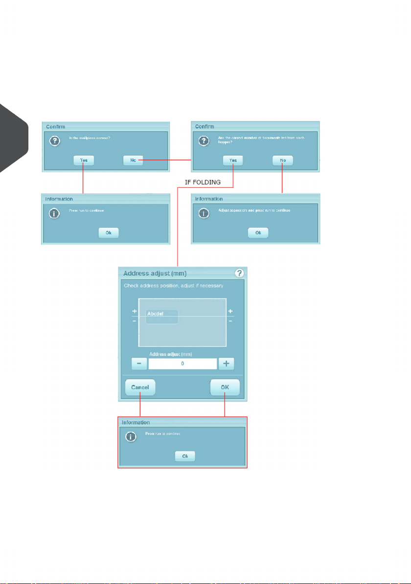
Address adjustment
After pressing the Run button, the first piece will be processed and the machine will stop
to allow you to adjust the vertical alignment of the address, if required.
Remove the filled envelope and adjust as necessary, as shown below:
4
English
12
Page 16
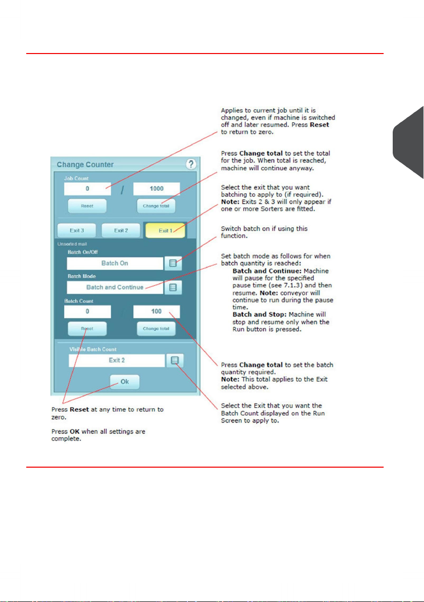
Counters Settings
Press the Edit button next to the counters to display the Change Counter box as
1.
follows:
4
English
13
Page 17

Adjusting the Envelope Inserter settings
Unit Fine Tuning
All fine adjustments apply only to the current job and will not affect
any other jobs. Note also that settings available will depend upon
user access rights (see User Access Right on page 24).
4
1. Select the inserter icon on the machine graphic in the Run screen to display the fine
tuning screen.
English
14
Page 18
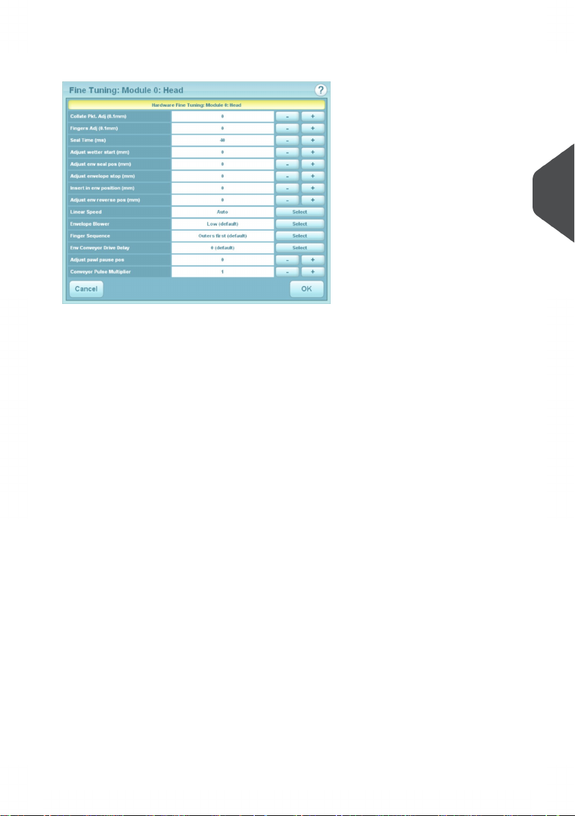
2. Select Hardware Fine Tuning to display further information.
You can change:
- The width of the collate pocket guides.
- The overall width of the insert fingers.
- The time allowed for the flap to seal before the envelope is ejected.
- Adjustment of the point at which the wetter beam drops to wet the flap. +ve
increases wetting in 1mm steps (moves start point towards insertion area).
- Adjustment of the amount of envelope travel into the sealing rollers. +ve = further
forward, away from exit direction.
- Adjustment of the envelope stop position for insertion. +ve = further forwards,
towards exit direction.
- Adjustment of the amount of insertion of the insert pack into the envelope. +ve
= further forwards past the flap crease.
- Adjustment of the amount of envelope forward travel after flap wetting, before
reversing to enter the sealing rollers. +ve = further forward into the output rollers,
towards the exit direction. for high-window envelopes, this should be set to
20 - 50mm +ve.
- Adjustment of inserter head speed. Set a lower speed if insert packs are not
being fully inserted, eg. for long packs.
- Control of blower fan which assists envelope opening. Increase to open envelope
more, eg. for thick packs, decrease for single sheets or thin packs.
- Changing finger sequence if envelopes are not opening properly. Try other
settings if this is the case.
- Adjustment of number of envelopes that will feed before the detection flags
switches the conveyor back on after it has stopped. Increase number if envelopes
are ‘bunching’.
- Adjustment of degree of pause of the insertion pawls after inserting pack.
Increase if pawls start moving too soon and contacting inserted pack before it
has moved towards closer.
- Control of the overlap of sealed packs on the output conveyor. Higher number
will increase conveyor speed and reduce overlap.
- Collate Slowdown: Select ‘Not on Last Form’ for thick packs if the final document
in the pack does not feed fully into the collate pocket.
4
English
15
Page 19

3. When all adjustments are complete, select the 'Unit' button for hopper settings, as
described below.
Hopper Fine Tuning
1. From here you can adjust hopper settings. Select the envelope icon on the machine
graphic in the Run screen then Document Fine Tuning to display further information.
4
English
You can change:
- Whether or not the envelope is sealed. Select ‘Off’ if, for example, later hand
insertion of an insert or any other item will be required.
- The setting of the amount of envelope deskew required. use higher settings
only when necessary – machine operates faster on lower settings.
All fine adjustments apply only to the current job and will not affect
any other jobs
16
Page 20

Adjusting the Document Unit settings
Unit Fine Tuning
The fine tuning options available will depend upon whether a
Feeder or Tower Folder is fitted. Note also that settings available
will depend upon user access rights (see User Access Rights on
page 24).
1. Select the document or insert icon on the machine graphic in the Run screen to display
the fine tuning screen.
4
English
17
Page 21

Hopper Fine Tuning
1. From here you can adjust hopper settings (depends per module due to DFC).
4
English
18
Page 22
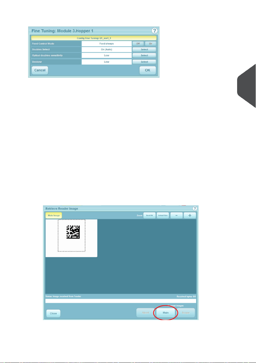
You can select:
- Feed Always or not. If you select Off, the unit is disused until it is turned back
on again.
- Whether doubles detection is turned on or off. Turn off if booklets or very thick
inserts are being fed. If turned on, select whether Optical or Mechanical detection,
or Auto (software decides).
- Optical doubles sensitivity (valid only if Optical Doubles On is selected). Low
set-ting is more tolerant to high contrast printing.
- Amount of deskew; use higher settings only when necessary – machine operates
faster on lower settings.
- Only for Reading units. Reset Seq. Count - if Sequence OMR marks are being
used and the job is disrupted for any reason, select this button to reset the
sequence.
- Only for Reading units. Retrieve CIS Image - if selected, images of the label
as seen by the CIS reader will be displayed. The images will be of the final 2
documents in the group and can be useful for error checking by confirming that
the whole label was read, for example, or comparing the 2 images.
-
4
English
19
Page 23
All fine adjustments apply only to the current job and will not affect
any other jobs
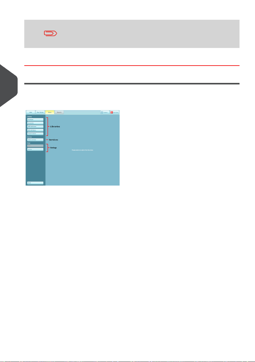
The Menu Screen
4
The Menu screen allows various functions to be selected. These functions are described
in detail further in this document.
English
20
Page 24
Running an existing job5
Running an existing job
This section describes running an existing pre-programmed job. To create a new job, see
Creating a job on page 26.
If the IMOS operating software is not already running, it must be started using the icon on
the monitor screen. To access the PC to switch it on, open the cupboard door below the
inserter head.
Before running a job, the paper hoppers must be loaded with stationery - see Loading the
paper hoppers on page 51 for details.
5
Paper is normally loaded in the Tower face-up and feet-first if
non-reading, but may be either way up if reading, depending upon
whether top or bottom reading. See also appendix A.
When using the cascade function, the Run button must be pressed
while the machine is still running, after you have reloaded the empty
hopper. This ensures the paper is fed to its pre-load position.
If this is not carried out the machine will stop, even though the
hopper is full: if this happens, press the Run button to continue.
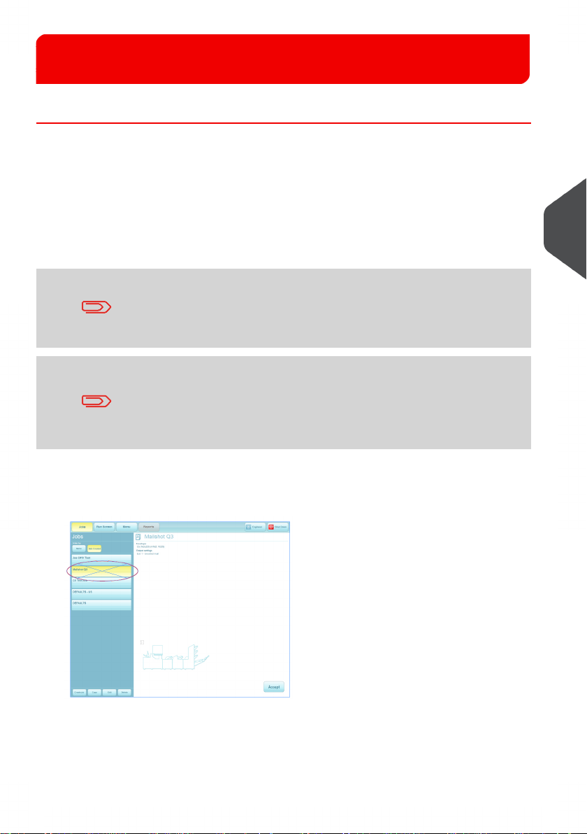
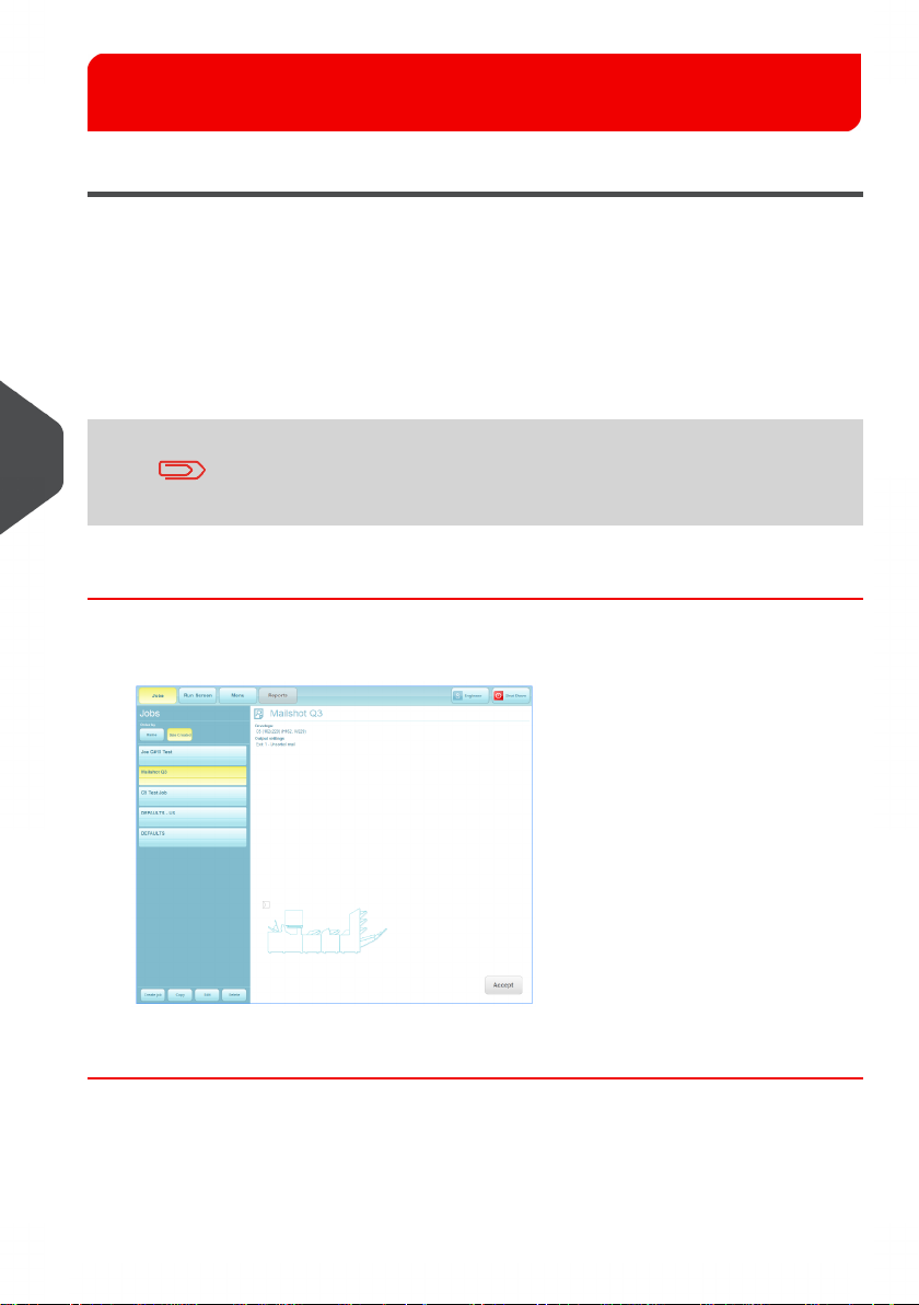
1. If the Job screen is not already displayed, press the Jobs button at the top and select
the required job from the list (use the scroll arrows if needed).
English
2. Summary of selected job is shown.
21
Page 25
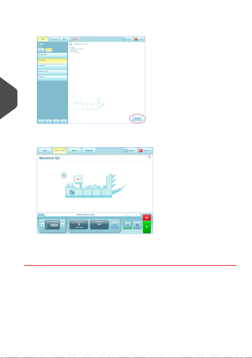
3. If you are happy with your selection, press Accept, otherwise, select another job.
5
English
4. Load the paper and envelopes in the hoppers indicated.
5. Press the Run button to begin operating.
See also The Run Screen on page 11 for a full description of the controls.
22
Page 26
Switching the user6
How to switch the user
Each user has their own password and access rights, allocated by the Supervisor. To switch
user, the password must be known.
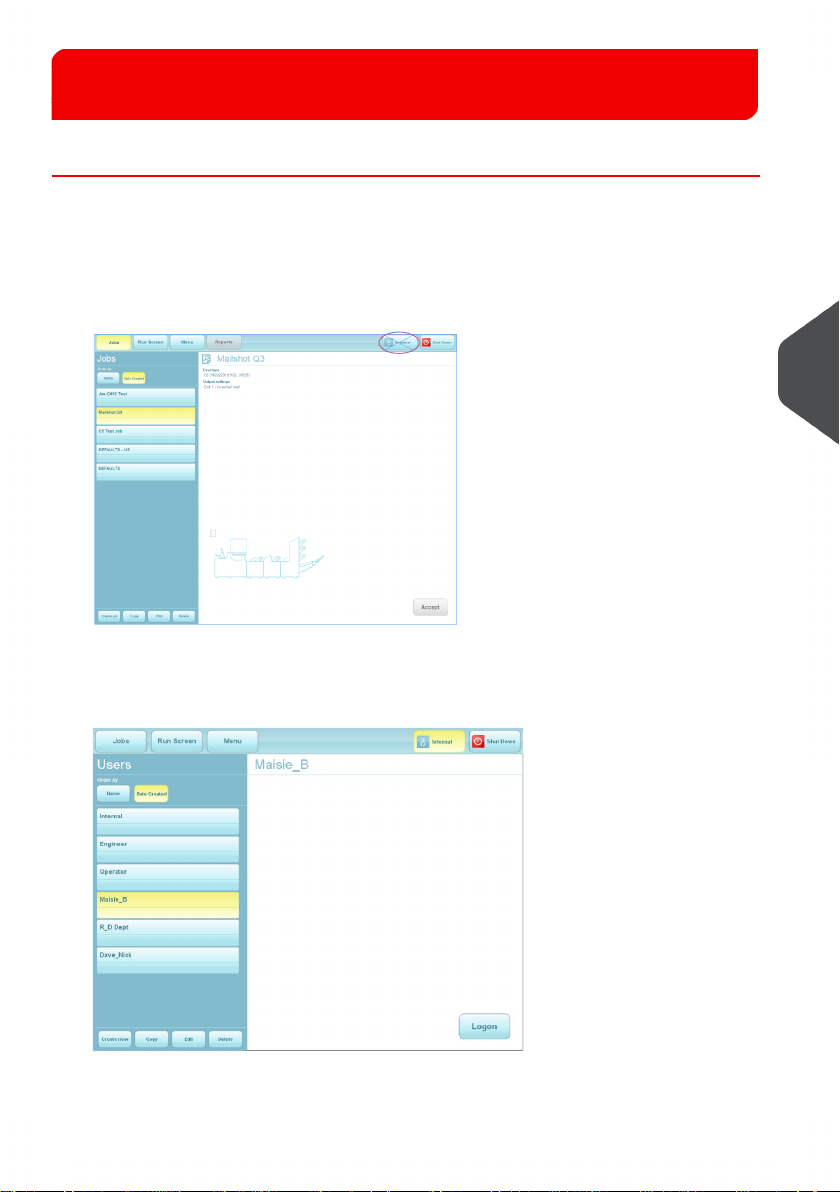
Press the Switch User button in the Job screen1.
2. Select the user from the list. Use the scroll arrows if necessary.
3. Press the Logon button.
6
English
23
Page 27
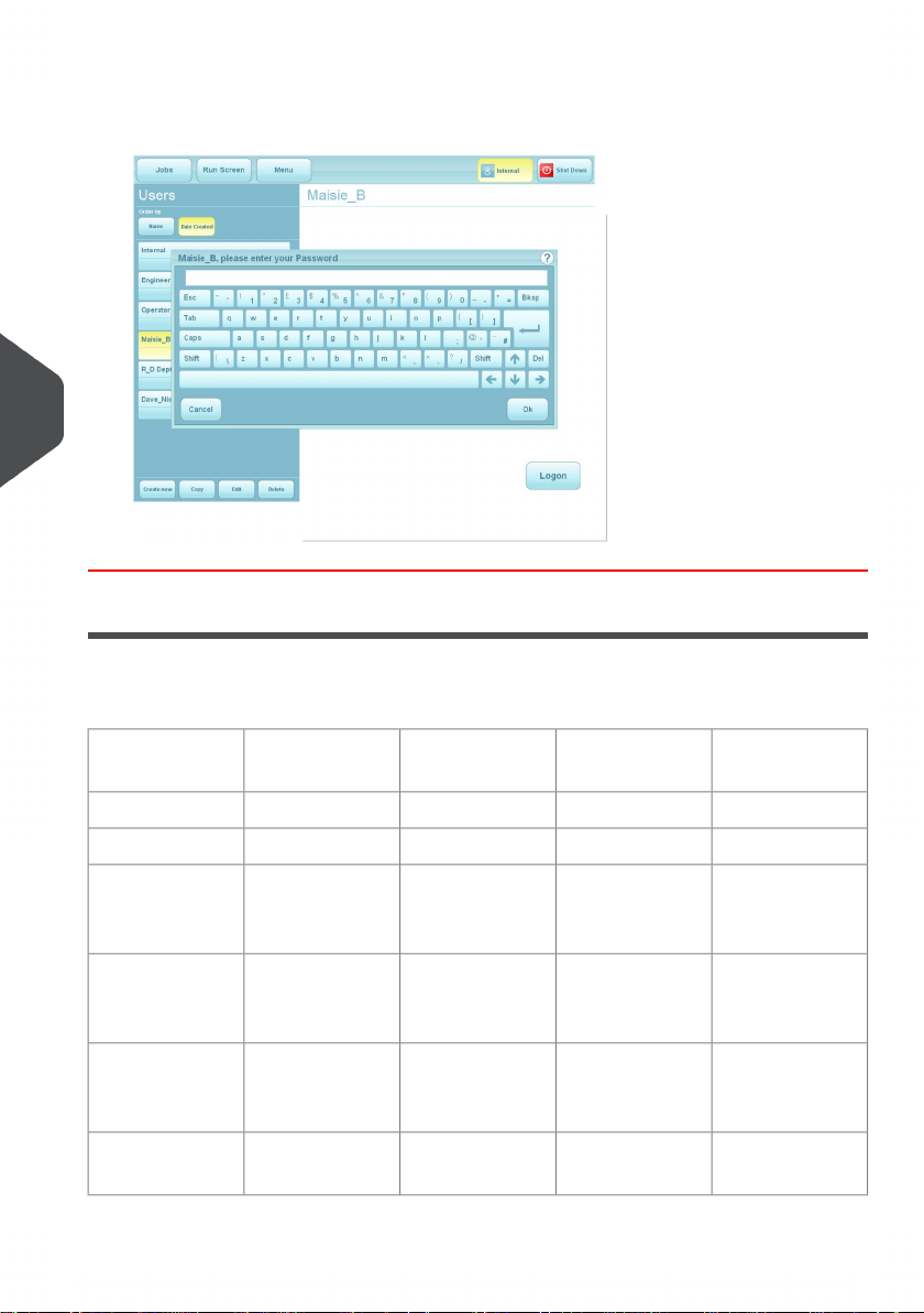
4. Enter the password using either the keyboard or the on-screen keypad. The user has
now changed.
6
English
User Access Rights
There are 4 levels of access rights that can be allocated to each user. These are described
below:
with
Wizard
raries
from Wizard
Libraries from
Outside Wizard
tuning
24
OperatorRights
Operator
SupervisorEngineerExpert
YYYYChange Jobs
YYYYRun Machine
YYYNProgramme Jobs
YYYNAdd items to Lib-
YYNNAdd Items to
YYNNMechanical Fine
Page 28

YYYNDocument Fine
tuning
YYNNEnter Service
Menu
YYNNEnter Admin
Menu
YYNNPC Shutdown
on Exit?
Additionally, the ‘System Security Level’ can be set by a Supervisor. This is the level where
a user does not have to enter a password to perform certain operations. Any access rights
needed above this level will require the user to logon with a password.
Level
of ‘Operator’
Expert OperatorLeast secureLow (default)
More secureMedium
Standard Operator
Operator can
run/edit/
create jobs but
cannot access
the main menu.
Operator can
only run jobs.
On StartupDescriptionEffective role
Job screen
displayed
Job screen displayed
6
English
NoneMost secureHigh
Operator’ has no
access
to the system. All
users
have to logon.
User screen
displayed
25
Page 29
Creating a job7
Creating a job
Creating a job consists of a number of steps:
• Defining the Mailset (Envelope, document & enclosures)
• Defining the Fold Settings
• Setting required Output Options
• Saving the Job to a Jobname
When defining the Document in the Mailset, OMR or Barcode definitions can be enabled
if required.
7
For an OMR of Barcode definition to be used it must first have been
created - see Creating a document
English
Creating the Job Settings
Press the Create Job button in the Job screen.
1.
You will now need to define the mailset (envelope, documents and enclosures). This
is described on the following page.
26
Page 30
Defining the mailset
Selecting the envelope
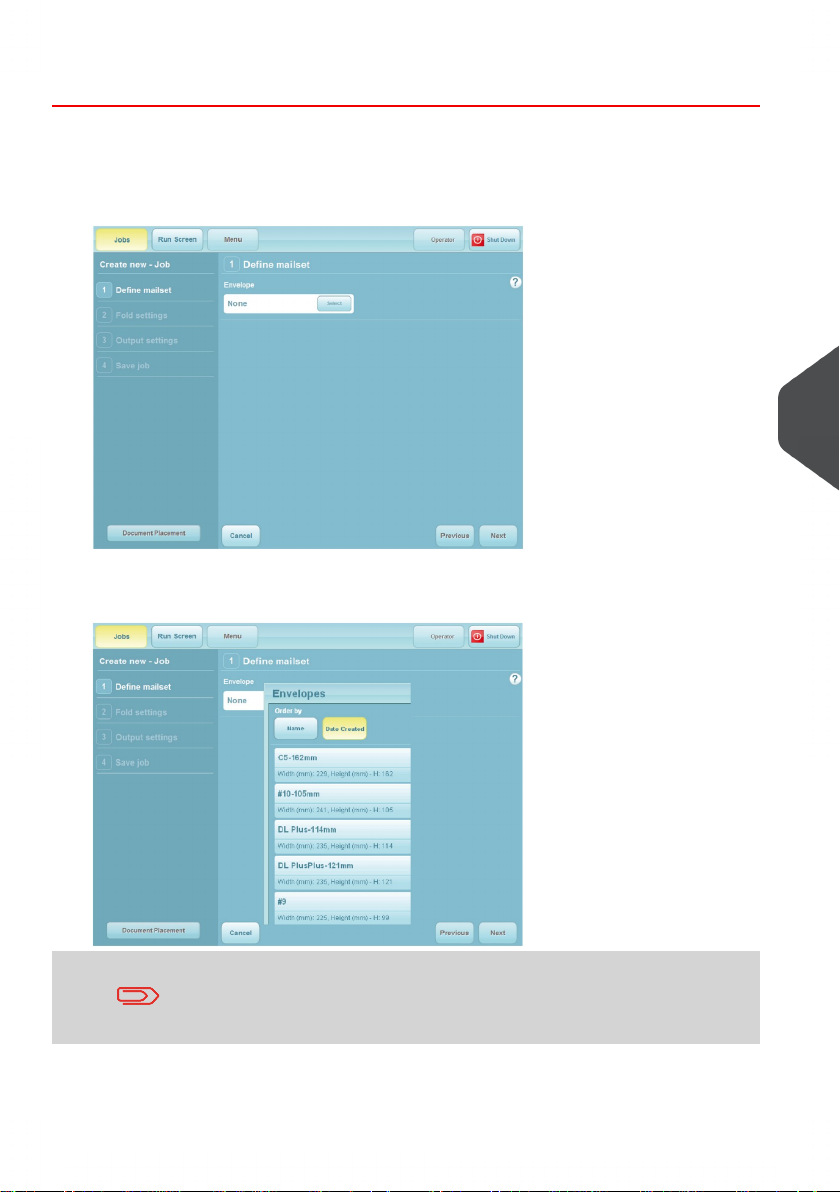
1. Press the Select button to choose an envelope from the available library.
2. Select the required envelope from the library and press the OK button.
7
English
If there are no envelopes in the library, or if you wish to create a
new one, see Creating an envelope on page 45.
27
Page 31

3. You now have a choice: carry on to select a document, or further define the envelope
usage, ie. sealing mode and deskew.
The following assumes you want to further define the envelope usage. When you have
finished you will return to the screen shown here.
Press the Settings button.
7
English
4. Select the required Sealing mode (usually this will be ‘Always’).Press the Edit
advanced button if you wish to change the deskew setting.
28
Page 32

5. From here, you can turn adjust the degree of deskew, or turn it off if you require. This
might be done to speed the machine up if, for example, an envelope is unlikely to
skew, eg. a C5 or other longer envelope. The default deskew setting is ‘Low’.
Selecting the document
1. Press the Select button to choose a document from the available library.
7
English
29
Page 33

2. Select the required document from the library and press the OK button.
7
English
3. You now have a choice: carry on to select enclosures, or further define the document
usage, eg. form count, cascading, hand-feed etc.
The following assumes you want to further define the document usage. When you
have finished you will return to the screen shown here.
Press the Settings button.
If there are no documents in the library, or if you wish to create a
new one, see Creating a document on page 47
30
Page 34

4. Adjust the forms count if using multiples, whether or not cascading is to be used,
whether or not daily mail (hand-feed) is to be used or whether or not External feed
(FFPD) is to be used. Press the OK button when done. For further settings, press the
Edit Advanced button.
7
English
31
Page 35

5. If you wish to choose an orientation other than the auto-selected default, press Auto
to enable the selector button.
7
English
If required adjust the degree of deskew, or turn it off if you require, for example if a
document type is found to feed reliably without skewing.
Thickness doubles can currently be checked optically only on a flex folder, or turned
off, if for example, documents are substantially different from the calibration document,
such as abnormally dark with heavy printing.
Selecting ‘Auto’ allows the software to choose between optical and mechanical
checking if the document is moved to a versatile feeder fitted with a mechanical system.
Feed control mode is ‘Feed Always’ as default, but can be turned off to disable the
hopper. It can also e set to ‘Selective Feed’ for reading-enabled units. This works in
conjunction with ‘Item ID’ .
Item ID allows you to define an ID number for the document which accords with the
relevant Select mark in the OMR or Barcode label. This will then feed the document
when that mark is read.
Sequence handling mode determines how sequence marks (if used) are handled
when a document set is broken up (for example, to change a job in the middle of a
document set). The mode must be set to ‘Full’ for the first pass, and then changed to
‘Mailset’ for the second pass after the job has been changed. The machine will not
then expect an unbroken sequence.
32
Page 36

Selecting the enclosure
1. If you are using enclosures (inserts, BREs, booklets etc.), press the Select button.
7
2. Select the required enclosure from the library and press the OK button.
If there are no enclosures in the library, or if you wish to create a
new one, see section Creating an enclosure on page 50.
English
33
Page 37

3. You now have a choice: carry on to select further enclosures if required, remove the
enclosure you have selected, or further define the enclosure usage, eg. form count,
cascading, handfold etc.
The following assumes you want to further define the enclosure usage. When you
have finished you will return to the screen shown here.
Press the Settings button. Settings and Advanced Settings are same for
enclosures as for documents- see steps 4,5 of section Selecting the document
7
English
Paper is normally loaded in the Tower face-up and feet-first if nonreading, face down and head-first if reading. This may vary: see
also orientation chart in Loading the flex folder hoppers
34
Page 38

4. If further enclosures are required, press the Select button and repeat steps 1 to 4.
Repeat as required up to the limit of available stations.
You now have a choice: to proceed and move on to Fold Settings, or to assign the
documents/enclosures to specific hoppers.
The following assumes you want to assign the documents/enclosures to specific
hoppers. This will override the hopper that the software automatically assigns.
If you do not want to assign the documents/enclosures to specific hoppers,
press the Next button shown in the previous screen.
Otherwise, press the Document Placement button shown in the previous screen.
This will display a placement box:
7
English
35
Page 39

5. Select the document that you want to move, then select the hopper that you want to
assign it to.
If you want to undo a manual placement, press ‘Auto place documents’ to revert.
Otherwise press ‘Save’.
7
English
The mailset is now defined, and the screen will show that this is chosen.
36
Page 40

Defining the fold
You will now define the fold settings.
The machine will automatically select the optimum fold type. If you wish to change
1.
this, deselect ‘Auto’ and set the required fold.
The machine may not perform properly if you change the fold
type incorrectly.
7
English
If you wish to make adjustments to the fold lengths, or just check them, press the
Adjust fold button.
37
Page 41

2. Make adjustments as required and press the OK button.
For Max. & Min. fold lengths for each fold plate, see ‘Technical
Specifications on page 81'.
7
English
3. If you wish to make adjustments to the collation mode or Max no. of sheets folded
together, press the Edit advanced button.
38
Page 42

4. Choose whether to collate leading edges of documents as they feed through the folder,
then folded together without entering the accumulator, or to feed separately into the
accumulator before folding. Sheets are fed singly by default, so each sheet is folded
and inserted separately. Set max number for folding together. Groups bigger than this
will be split into a) max number, followed by b) remainder.
The maximum that can be fed into the accumulator defaults to 9 (Max. collate), but
can be up to 25.
This will depend upon the paper type.
7
English
Multi-envelope mode allows two separate jobs to be run in succession using the same
document set. If set to ‘Split Oversize’, this splits, folds and inserts as for ‘Max Fold’
described above. If set to ‘Divert Oversize’, all groups numbering greater than the
number set in ‘Divert/Split Threshold’ will be diverted to the divert tray, and if set to
‘Divert Undersize’, the same will apply for groups below the threshold.
The machine is then stopped, the job is changed and the forms in the divert tray are
put back into the document set, and the new job is run.
‘Divert Action’ allows the option of the machine stopping automatically upon divert, or
to continue, allowing the operator to intervene.
When you have finished, fold settings are now complete and the screen will show that
this is ticked.See also Table 1 on the following page.
Table 1
Handling of folded forms
Shown below are handling of oversized/undersized groups under different
circumstances.
39
Page 43

7
English
Multi envelope
mode
Split oversized
Divert oversized
Divert undersized
Maximum Fold
When folding,
the group or
sub-group is folded on reaching
this limit
Not used (As for
Split Oversize if
oversize not yet
detected).
Not used (As for
Split Oversize if
undersize not
yet detected).
Maximum in
accumulator
When not folding or diverting,
the group or
subgroup is
ejected towards
divert or head
unit on reaching
this limit
Not used (As for
Split Oversize).
Not used (As for
Split Oversize).
Divert/Split
threshold
Not used
The complete
group is assembled in the
accumulator
and then diverted if prime document count is
equal or greater
than this limit
The complete
group is assembled in the
accumulator
and then diverted if prime document count is
less than this
limit
Comment
Mechanical limits of folder and
accumulator for
given stationery
Typically used
for diverting
large groups for
re-processing
into a larger envelope
Typically used
for diverting
small groups for
re-processing
into a smaller
envelope
40
Page 44

Defining the output settings
Select Settings for Unsorted Mail in the Output Settings screen.1.
7
English
41
Page 45

2. Set Batching to Batch On if required and set required quantity in Batch Quantity.Set
Batch Mode as follows:
Batch and Continue:
Machine will pause for the specified pause time, and then resume.
Conveyor will continue to run during the pause time.
Batch and Stop:
Machine will stop and resume only when the Run button is pressed.
Select Envelope Count under Batch Control, currently the only available option.
Set the Batch Complete Pause Time as described in Batch and Continue above.
When settings are complete, press the Save button.
7
3. If a conveyor is fitted, select Conveyor Settings to adjust the Jog functions as follows:
Single Jog Adjust: Adjusts default jog step (gap) between mailpieces. Note that steps
English
are unitless.
Batch Complete Jog Step: Adjusts gap before machine performs action described
in ‘Batch Mode’.
Mark Reading Jog Step: Adjusts gap created after Jog mark is read.
Autoend Jog Step: Adjusts gap created before machine autoends.
When settings are complete, press the Save button.
42
Page 46

Output Settings for unsorted mail are now complete. If you are using Mail Sorting,
refer to the INF Output Sorter Operator Manual.
The output settings are now defined, and the screen will show that this is ticked.
You will now save the job.
7
English
43
Page 47

Saving the job
Press the keyboard icon to display the virtual keyboard.1.
7
English
2. Enter a name for the job using either the virtual or physical keyboard.
Repeat steps 1 & 2 to enter a brief description for the job. This is the description that
will appear in the job list when the machine is started.
3. Enter a name for the job using either the virtual or physical keyboard.
You have now successfully created a new job and it will appear in the job list.
44
Page 48

Creating an envelope
In order for an envelope to appear in the envelope library, it must first be created.
Begin creating a job (see Creating the Job Settings on page 26)1.
2. At the point where you need to select an envelope, press the Create New button.
3. Enter a name for the envelope: press the virtual keyboard icon and enter the name
using either the physical or virtual keyboard.
Select an envelope type. The default width and height for that type will then be shown.
If you want to adjust the size, the type will change to ‘Custom’.
If you want to adjust the envelope weight and flap depth, press the Edit Advanced
button.
7
English
45
Page 49

4. Adjust the weight as required. Note that the weight is the actual weight of the envelope,
not the paper weight.
Adjust the wetting rate if required. The number shown is the quantity of envelopes
sealed before the pump tops up the wetter tank. Default is 25.
Press the Save button when done.
The envelope will now be available in the envelope library under the name you have
given it.
7
English
The envelope is now fully defined and is available for use.
46
Page 50

Creating a document
In order for a document to appear in the document library, it must first be created.
Begin creating a job (see Creating the Job Settings on page 26)1.
2. At the point where you need to select a document, press the Create New button.
3. Enter a name for the document: press the virtual keyboard icon and enter the name
using either the physical or virtual keyboard.
Select a document type and size and orientation. The default width and height for that
type will then be shown. If you want to adjust the size, the type will change to ‘Custom’.
Change the thickness for thick documents, eg. booklets. If you want to make further
adjustments, or select a reading definition, press the Edit Advanced
7
English
47
Page 51

4. Select the address position. This defaults to ‘Top’; specify middle, bottom or none if
required.
Specify whether the document is to be folded (eg. a booklet would not be) and its
thickness and weight. Note this is the actual weight of the document, not the paper
weight.
The thickness is more applicable to booklets - if no figure is specified, 80gsm paper
will be assumed.
If the document uses an OMR or barcode label, select a reading definition.
This is obtained under licence as an option and must already
exist on the machine.
7
English
If the document does not use an OMR or barcode label, press the Save button,
otherwise, proceed as follows.
48
Page 52

5. Press the Region of Interest button to specify the position of the label.
6. Specify the position of the label and select whether edge detection is required – this
detects the edge of the paper and should normally be On.
Turn Off if coloured or densely printed paper is giving false readings: the machine
will then use default dimensions for label position. Press the Save button when done.
The document is now fully defined and is available for use.
7
English
49
Page 53

Creating an enclosure
In order for an enclosure to appear in the enclosure library, it must first be created.
Begin creating a job (see Creating the Job Settings on page 26)1.
2. At the point where you need to select an enclosure, press the Create New button.
7
English
3. The procedure for defining an enclosure is the same as that for a document, described
in Creating a document on page 47. It is the document type that you select that
determines whether it appears in the document or enclosure library.
See Creating a document on page 47 for the remainder of the settings.
The enclosure is now fully defined and is available for use.
50
Page 54

Loading the paper hoppers8
Loading the envelope hopper
Using the black knob, adjust the side guide to give 1-1.5mm clearance each side of
1.
the envelope.
8
English
51
Page 55

2. Adjust the angle of the backrest (see below) and load the envelopes into the hopper,
flaps forward, so that the lower edges follow the contour of the surface and down into
the pick-up roller. Move the backrest forward (see below) so the the envelopes are
fully forward, but not tightly packed.
8
English
3. Move the backrest forward by squeezing the handle upwards to release the rollers
from the track.
Adjust the width of the panels to suit the envelope.
Adjust the angle by loosening the knob each side.
C4: Fully raised
DL/DL+: Fully lowered
52
If the envelopes feed erratically, try a backrest angle in-between.
Page 56

Adjusting the envelope separator
The separator prevents more than one envelope being fed at a time.
1. To adjust the separator, open the side cover on the insertion head; the adjustor knob
is visible below the envelope conveyor. Turning clockwise decreases the gap,
anti-clockwise increases it.
2. To set the separator gap, empty the hopper, then slide an envelope into the gap and
turn the knob until the separator will just grip the envelope as you withdraw it.
3. Close the side cover when you have finished.
8
English
53
Page 57

Loading the feeder hopper
Move the guides to give 1 - 1.5mm clearance each side of the insert.1.
8
English
2. Draw back the weighted rollers and load the insert pack so that the leading edge is
feeding into the nip of the feed rollers. Move the weighted roller forward to support
the pack.
Tower feeder is shown; single feeder is similar, with one hopper
only.
Adjusting the separator
The separator prevents more than one enclosure being fed at a time.
1. The feeder separator has 4 settings, marked A to C on the slide. Before running the
job, the gap must be set to suit the thickness of material being processed - this prevents
54
Page 58

more than one item being fed at a time. Note that there is an intermediate setting
between each marked position, allowing finer adjustment.
Slide positions:
A = 0 to 0.75mm
B = 0.75 to 1.5mm
C = 1.5 to 2.5mm
D = 2.5 to 4.0mm
(A - C only on Tower Feeder)
Most jobs will use position A. If you use the wrong setting, an error
will appear on the control panel.
8
English
For problem enclosures, the feed rollers can be changed to optional
alternatives.
55
Page 59

Loading the tower folder hoppers
The tower folder may be fitted with 500-sheet or 1000-sheet hoppers, or only a single
00-sheet hopper. The example shown has 1 x 500-sheet and 1 x 1000-sheet hoppers.
1. On 500-sheet hoppers, ORRVHQ the black knob next to the side guides (arrowed) and
move the guides to give 1-1.5mm clearance each side.
On 1000-sheet hoppers, press down on the tray to lower it. /RRVHQ the black knob
above the hopper (arrowed) and use the tabs to move the guides to give 1-1.5mm
clearance each side. The tray will raise automatically when the machine is started.
8
2. Tighten the knobs.
56
Paper orientation in the hoppers will depend upon the job
requirement - see the paper orientation chart.
Page 60

Accumulator
7KH accumulatorVide guides must be adjusted
to suit the paper - use the preset size markings to set the paper width.
8
1. Raise the top of the accumulator so that it locks in place and place a piece of paper
between the side guides.
2. Loosen the black knob next to the side guides (arrowed) and move the guides to give
1-1.5mm clearance each side.
3. Pull out the handle at the end (arrowed) to lower the accumulator top.
English
57
Page 61

Adjusting the separator
The separator prevents more than one document being fed at a time.
1. Open the side cover on the operator side and turn the knob in the required direction
to open or close the gap. The markings next to the knob indicate which direction to
turn it.
8
English
58
Page 62

2. To set the separator gap, empty the hopper, then slide a form into the gap and turn
the knob until the separator will just grip the form as you withdraw it.
Table 2
Paper Orientations
Paper orientations for various applications are shown below.
European Sizes:
Tower Fold
Configurations
UK & European Sizes
Job
Code
CF1
CF2
Job
Description
A4
Form
(297mm
x
210mm)
Document
printed
with
top address
A4
Form
(297mm
x
210mm)
Document
middle
address
Fold
Type
"C"
Fold
"C"
Fold
Face
Down
Head
First
Face
Down
Feet
First
Face
Up
Feed
First
Fold Pannel LengthsForm Input Orientation
Fold
Plate
1
68mm
(121mm
long
envelope
90mm
(110mm
envelope)
183mm
(121mm
long
envelope)
194mm
(110mmprinted
envelope)
FoldPlate
2
115mm
(121mm
long
envelope )
104mm
(110mm
longlongwith
envelope)
FoldPlate
3
115mm
(121mm
long
envelope)
104mm
(110mm
longlong
envelope)
8
English
59
Page 63

8
English
CF3
ZF1
ZF2
A4
Form
(297mm
x
210mm)
Document
printed
with
bottom
address
Address
upside
down
in window
A4
Form
(297mm
x
210mm)
Document
printed
with
top address
A4
Form
(297mm
x
210mm)
Document
printed
with
top address
"C"
Fold
"Z"
Fold
"Z"
Fold
60mm
(121mm
long
envelope)
90mm
(110mm
long
envelope)
229mm
(121mm
long
envelope)
103mm
(110mm
long
envelope)
68mm
(121mm
long
envelope
90mm
(110mm
long
envelope)
115mm
(121mm
long
envelope)
104mm
(110mm
long
envelope)
115mm
(121mm
long
envelope)
104mm
(110mm
long
envelope)
115mm
(121mm
long
envelope)
104mm
(110mm
long
envelope)
60
ZF3
"Z"
Fold
Page 64

VF1
VF2
A4
Form
(297mm
x
210mm)
Document
printed
with
bottom
address
A4
Form
(297mm
x
210mm)
Document
printed
with
top address
A4
Form
(297mm
x
210mm)
Document
printed
with
bottom
address
Address
upside
down
in window
"V"
Fold
"V"
Fold
114mm
(121mm
long
envelope)
103mm
(110mm
long
envelope)
149mm
149mm
115mm
(121mm
long
envelope)
104mm
(110mm
long
envelope)
8
English
61
Page 65

8
English
DFF1
DFF2
Europcon
16"
torm
(106mm
x
210mm)
Document
printed
with
top address
Europcon
16"
torm(106mm
x
210mm)
Document
printed
with
bottom
address
Address
upside
down
in window
Double
Forward
Fold
Double
Forward
Fold
177mm
(121mm
long
envelope)
199mm
(110mm
long
envelope)
177mm
(121mm
long
envelope)
199mm
(110mm
long
envelope)
115mm
(121mm
long
envelope)
104mm
(110mm
long
envelope)
115mm
(121mm
long
envelope)
104mm
(110mm
long
envelope)
62
American Sizes:
Page 66

D16403 Tower Fold
Configurations
American Sizes
Job
Code
ACF1
ACF2
Job
Description
US Letter
format
(11" x
8½")
Document
printed
with
top address
US Letter
format
(11" x
8½")
Document
printed
with
middle
address
Fold
Type
Fold
"C"
Fold
Face
Down
Head
First
Face
Down
Feet
First
Face
Up
Feed
First
Fold Pannel LengthsOrientation In Hopper
Fold
Plate
1
02mm
(#10"C"
Envelope)
181mm
(#10
Envelope)
FoldPlate
2
99mm
(#10
Envelope)
FoldPlate
3
99mm
(#10
Envelope)
8
English
63
Page 67

8
English
ACF3
AZF1
AZF2
AZF3
US Letter
format
(11" x
806")
Document
printed
with
bottom
address
US Letter
format
(11" x
8½")
Document
printed
with
top address
US Letter
format
(11" x
806")
Document
printed
with
top address
US Letter
format
(11" x
8½")
Document
printed
with
bottom
address
"C"
Fold
"Z"
Fold
"Z"
Fold
"Z"
Fold
82mm
(#10
Envelope)
197mm
(#10
Envelope)
98mm
(#10
Envelope)
140mmAVF1
82mm
(#10
Envelope)
33mm
(#10
Envelope)
99mm
(#10
Envelope)
99mm
(#10
Envelope)
99mm
(#10
Envelope)
64
Page 68

AVF2
AD-
FF1
US Letter
format
(11" x
8½")
Document
printed
with
top address
US Letter
format
(11" x
8½")
Document
printed
with
bottom
address
Address
upside
down
in window
US
Legal
format
(14" x
8½")
Document
printed
with
top address
"V"
Fold
"V"
Fold
Double
Forward
Fold
110mm
197mm
(# Envelope)
8
English
99mm
(#10
Envelope)
65
Page 69

US
Legal
format
(14" x
8½")
Document
ADFF2
printed
with
bottom
address
Address
upside
down
in window
Double
Forward
Fold
197mm
(# Envelope)
8
English
Daily Mail (Tower Folder)
Daily mail allows a group of forms to be hand-fed, folded and inserted on a Flex Folder or
Versatile Feeder. This section descibes the Flex Folder – see Flex Folder for Versatile
Feeder.
A group of forms up to a total of 6mm thick may be fed, but be aware of the folding capacity
of 8 forms of 80gsm (20lbs bond). The forms may be stapled or not, as required (see below
for stapling restrictions).
99mm
(#10
Envelope)
Stapling Restrictions
66
Page 70

Using Daily Mail
To use daily mail, define a new mailset (as described in Defining the mailset on page 27)
or edit the document settings in an existing job.
Select Settings for the document and set ‘Hopper feed mode’ to Daily Mail.
8
English
67
Page 71

When daily mail has been enabled as described, press the Run button and feed the post
into the accumulator tray. The machine will wait for 30 seconds after pressing the button if you exceed this before inserting the documents, press the button again.
To turn the function off, switch ‘Hopper feed mode’ back to Default in Document Settings.
You may find it easier to feed the paper by unhooking the divert
tray and removing it.
8
English
68
Page 72

Adjusting the catch tray
If a Catch Tray is being used for ejected envelopes, it should be adjusted to suit the
ejected envelopes.
8
English
69
Page 73

Operator Maintenance9
Cleaning the sensors
The optical sensors consist of two halves: emitter and receiver. These can become
obstructed due to paper dust and should periodicaly be cleaned using a nonflammable
airduster. Both halves must be cleaned.
This section shows where the sensors are located. For most sensors, an indicator arrow
is pierced showing you where the jet of the airduster should be directed. For some sensors,
the retaining bush is visible next to the lens: ensure you spray into the lens, not the bush.
Cleaning the sensors
Sensors are retained with a bush next to the lens: where this is
visible, ensure that you spray into the lens (arrowed), not the bush.
9
Insertion head
English
Direct the airduster into the openings arrowed and spray liberally.
1. Open the perspex top cover and raise the collate clamshell (closest to the envelope
hopper) so that it locks in place.
Picture shown is viewed looking inside the collation area towards the envelope hopper
70
Page 74

2. Picture is viewed looking inside the collation area away from the envelope hopper.
Clean all sensors arrowed.
3. Lower the collate clamshell and open the upper conveyor (furthest from the envelope
hopper) so that it locks in place.
Picture is viewed looking inside the collation area away from the envelope hopper.
Insert the airduster nozzle deep into the hole and spray liberally. Note the the upper
sensor half is not easy to see and is mounted on a bar.
Lower the conveyor.
9
English
71
Page 75

4. Lower the side cover and raise the overguide inside the closer cavity, latching it in
place.
Clean the sensors arrowed.
9
5. Picture is viewed looking down on the envelope hopper, at the front.
English
Clean the one-piece reflective sensor.
72
Page 76

6. Lower the front output cover below the envelope feeder.
Clean the sensors indicated. Note that the upper sensor is in two halves. The lower
sensor is a one-piece reflective type.
Feeder
There is a sensor on the feed hopper of a feeder, and a pair located in the lower
conveyor section.
1. Remove all paper from the feed hopper and direct the airduster into the cutout indicated.
9
English
73
Page 77

2. Open the side cover and push the lowermost lever forward to lower the conveyor.Clean
the sensor located next to the gearwheel in the centre of the track as shown, with the
upper half directly above it.
9
A single feeder is shown, twin-feeder is similar. Conveyor sensor
English
applies also to feederfolder.
Feeder-Folder
There is a sensor in the front transport assembly on a feeder-folder, and another two
on the top. There is also one in the lower conveyor (see Feeder).
1. Raise the cover at the front of the feederfolder. Using the blue tab, release the latch
of the transport assembly and lift it upwards. Direct the airduster into the cutouts
indicated.
74
Page 78

Ensure the lever is fully latched when closing.
2. Raise the top cover. Direct the airduster into the cutout (the lower sensor in the picture),
and into the gap to clean both halves of the upper sensor.
9
English
75
Page 79

Flex Folder
1. Open the folder top cover and clean the sensors indicated.Direct the jet into the gap
under the sensors, or into the hole indicated.
9
English
76
Page 80

2. Open the top cover open, direct the jet into the holes indicated.
Note: The sensors are in two halves, with the opposite halves located in the cover.
9
English
77
Page 81

Clearing paper jams
If paper jams occur, the area affected will normally be shown in the error message on the
screen. Use one of the clearance methods described below to clear the jammed paper.
Inserter Head
1. Open the side cover on the operator side of the machine, and lower the front sealer
cover.
9
English
Check for jammed paper in the open cavities.
If the paper is not fully visible, turn the blue knobs to wind it into view.
Open the front closer cover using the blue tab and check for jammed paper.
78
Page 82

Feeder (Single and Twin) & Feeder Folder
1. Open the side cover on the feeder.
Use the blue tabs to push forward the levers indicated to open the cavities and access
the jammed paper.
If the paper is not fully visible, turn the blue knobs to wind it into view.
single feeder is shown; twin-feeder and feeder-folder are similar.
9
Tower Folder
1. Open the side cover on the flex folder.
Base Unit
Using the blue tab, open the folder assembly to access the jammed paper.
If the paper is not fully visible, turn the blue knobs to wind it into view.
Page 83

9
English
When closing the folder assembly, ensure it is fully latched on both sides.
Tower Unit
Using the release handle, open the top cover to access the jammed paper.
If the paper is not fully visible, turn the blue knobs to wind it into view.
80
Page 84

Technical Specification10
Inserter head
Parameters
Pack thickness
Maximum pack thickness is defined as the internal dimension of
a rigid opening that a filled envelope will fall through under its
own weight.
up to 6mm (¼”)All envelope sizes:
Pack clearance
10
Cycling speed
Monthly volume
The minimum clearances required between the inserts and envelopes
are dependent on insert pack thickness.
Clearance is the total clearance and is defined as the difference between
the largest overall dimensions of the pack and the internal dimensions
of the envelope (see below). The required clearances are summarised
as follows:
Pack <3mm: Depth 6mm (¼”) Width 16mm (5/8”)
Pack >3mm <6mm: Depth 12mm (½”) Width 19mm (¾”)
English
Series: Up to 4500 envelopes per hour (based on 1 xOHWWHU folded
sheet into a envelope).
;7 Series: Up to 5500 envelopes per hour (based on 1 xOHWWHU folded
sheet into a envelope).
Speeds for other conditions available on request.
Series: Up to 150,000 filled envelopes per month.
;7 Series: Up to 180,000 filled envelopes per month.
81
Page 85

Envelope
weight
General envelope requirements
-er capacity)
Envelope details
10
English
Minimum: 70gsm (18lbs bond)
Maximum: 100gsm (28lbs bond)
• Envelope to be good quality machine-fill type. Dimensions and
quality to be consistent across manufactured batches.
• Side seams must be securely glued to the top of the seam.
• Flap crease must be pre-scored to enable the envelope flap to
open flat.
• No glue seepage must be evident on interior or exterior of envelope.
• Windows to be securely affixed to within 1.5mm
(1/16”) of top and side edges. Top edge to be flat and
free from puckering.
Up to 00 filled envelopes (assumes 1 document inserted)2XWSXWFRQYH\
82
Page 86

10
English
83
Page 87

Envelope sealing fluid
10
Tower Folder
English
Parameters
Paper Size
Paper weight
Built-in wetter tank, automatically pump-fed by 10-litre wetter container
located in stand. Optional low-level float switch available.
Minimum width: 140mm (5½”)
Maximum width: 228mm (9”)
Minimum length: 140mm (5½”)
Maximum length: 406mm (16”)
Note: The maximum suggested width difference between inserts is
32mm (1¼”): this may be increased subject to test. If this difference
is exceeded, the insertion fingers will not cover the edges of the narrow
insert and may cause insertion problems. Sandwiching a narrow insert between two wider ones may resolve this.
Minimum 60gsm (16lbs bond)
Maximum 120gsm (32lbs bond) for folded documents
Maximum 4mm thick for unfolded inserts (subject to test)
84
Page 88

Folding capa-
1000
city
Fold lengths
Hopper capacity
C, Z or V-fold: 8 sheets 80gsm (20lbs bond)*
Double-forward fold: 4 sheets 80gsm (20lbs bond)*
* Up to 2 x 8 split sets into one envelope dependent upon
pack thickness.
Fold Plate 1: 229mm Max, 48mm Min.
Fold Plate 2: 229mm Max, 50mm Min.
Fold Plate 3: 202mm Max, 50mm Min.
Tower Folder can be ordered in 3 configurations as follows:
3 x 500 sheets of 80gsm (20lbs bond)
1 x 1000 sheets of 80gsm (20lbs bond)
1 x 500 + 1 x 1000 sheets of 80gsm (20lbs bond)
10
English
Daily mail
Up to 8 sheets of 80gsm (20lbs bond) for C, Z or V fold, up to 4 sheets
of 80gsm (20lbs bond) for double forward fold. May be stapled or not.
Max. thickness of staple 3mm. Allowable staple positions are shown
below.
85
Page 89

Insert Feeder
Insert Sizes(Single hopper)
Paper weight
Hopper capacity
10
Insert Sizes(Tower hopper)
English
Paper weight
Hopper capacity
Parameter
Minimum width: 140mm (5½”)*
Maximum width: 241mm (9½”)
Minimum length: 76mm (3”) for module 1
89mm (3½”) for following
modules
Maximum length: 152mm (6”)
*For individual items. Min. pack width:
210mm (8¼”)
Minimum 60gsm (16lbs bond) min.
Maximum 4mm (5/32”) thickness
Up to 300 BREs or 150 2mm booklets
Note: Quantities shown above are maxima.
Depending
upon other conditions, actual quantities may
be lower
than those shown.
Minimum width: 140mm (5½”)*
Maximum width: 241mm (9½”)
Minimum length: 76mm (3”) for module 1
89mm (3½”) for following
modules
Maximum length: 152mm (6”)
*For individual items. Min. pack width:
210mm (8¼”)
Minimum 60gsm (16lbs bond) min.
Maximum 2mm (5/64”) thickness (top tray)
Maximum 4mm (5/32”) thickness (lower tray)
Up to 200 BREs or 100 2mm booklets
Note: Quantities shown above are maxima.
Depending
upon other conditions, actual quantities may
be lower
than those shown.
86
Page 90

Requirements
Feeder Folder
Parameters
Depth:
Width:
Thickness:
Enclosures must be flexible enough to suit
path constraints.
Some enclosures may require special tyres.
140mm (51/2”) min. (89mm (3½”) for unfolded inserts)
406mm (16”) max. (139mm (5½”) for unfolded inserts)
140mm (51/2”) min. (Widths below 168mm
(6.6”) require narrow finger kit A3348A).
229mm (9”) max.
60gsm (16lbs bond) min.
70gsm (18lbs bond) min. for OMR/Barcode
paper
120gsm (32lbs bond) max.
10
Depth of output doc:
Daily Post:
89mm (31/2”) min.
152mm (6”) max.
Up to 500 sheets of 80gsm (20lbs bond)Hopper capacity:
Up to 3 sheets (C or Z fold) or 5 sheets (V
fold) of 80gsm (20lbs bond). May be stapled
or not, but staples on ‘Z’ fold only. Max.
thickness of staple 2mm. Allowable staple
positions shown below. Note: all daily post
forms must be the same length.
Note: Daily Post is not available as an option
if a CIS reader is fitted.
English
87
Page 91

Mechanical & Electrical
Noise level:
<73dbA (following ISO 11202).
Electrical:
115VAC230VAC
60Hz50HzFrequency
2AHead: 1AInput Current
1ASingle Feeder: 0.5A
1ATwin Feeder: 0.5A
1ACIS Feeder: 0.5A
2ATower Folder: 1A
10
Power Requirement and Voltage Tolerance:
230V / 50 Hz (voltage tolerance +10%/10%)
115V / 50/60 Hz (voltage tolerance +6%/10%)
Operating Temperature:
English
10 - 40 deg C (50 - 104 deg F)
Operating humidity:
30 - 80% RH
Display Properties:
Dimensions:
Inserter Head
15”Screen Size:
1024 x 768 pixelsScreen Resolution:
Full Colour Touch ScreenScreen Technology:
720mm (28.3”)Length:
475mm (18.7”)Width:
88
Page 92

Tower Folder
Feeder Folder
Reading Feeder
600mm (23.6”)Height:
56Kg (123lbs)Weight:
490mm (19.3”)Length:
475mm (18.7”)Width:
915mm (36.0”)Height:
75Kg (165lbs)Weight:
408mm (16.0”)Length:
475mm (18.7”)Width:
710mm (27.9”)Height:
43Kg (95lbs)Weight:
10
408mm (16.0”)Length:
475mm (18.7”)Width:
550mm (21.6”)Height:
25Kg (55lbs)Weight:
English
Single Feeder
Twin Feeder
408mm (16.0”)Length:
475mm (18.7”)Width:
520mm (20.4”)Height:
25Kg (55lbs)Weight:
408mm (16.0”)Length:
89
Page 93

Processing Speed
Ambient light:
Although the machine may operate in sunlight, it is not designed for use in direct sunlight,
or where sunlight is exposed to the machine through windows or skylights. The light-sensitive
sensors can be affected in these conditions. It is therefore recommended to:
1. Locate the machine out of direct sunlight
2. Protect the machine from direct sunlight using blinds or similar blocking devices.
10
If the machine can only be located where it may be exposed to direct sunlight, then please
contact Technical Support department, who may be able to advise on the use of blocking
material on the inside of the Perspex cover where necessary.
English
475mm (18.7”)Width:
700mm (27.6”)Height:
25Kg (55lbs)Weight:
4500 filled envelopes per hour.6HULHV:
5500 filled envelopes per hour. ;76HULHV:
1. All stationery should be allowed to acclimatise near the
machine for at least 24 hours before use to prevent rapid
absorption of moisture in the material, or condensation forming
on the machine. Failure to acclimatise the material may cause
pre-gumming of envelopes or otherwise impair machine
performance.
2. The machine will function with humidity levels lower than 30%
RH, but high levels of static may be generated, impairing
machine performance.
3. The machine will function with humidity levels higher than 80%
RH, but moisture absorption into the material may impair
machine performance.
4. Condensation must not be present under any circumstances.
5. The machine will function at temperature levels above 28 deg
C (82 deg F) and below 18 deg C (64 deg F). However,
temperature levels outside these limits may impair the machine
performance.
6. Material processed directly from laser printers may have high
levels of static causing material to stick together. If double
feeding occurs, then Hi-Grip separators may be required contact IPSS department.
90
Page 94

Glossary of terms11
Glossary of terms
Address carrier
Address position
DescriptionTerm
The address carrier is the document that
carries the address of the person for who the
mail set is meant. The address carrier can
consist of one or more sheets, from which
at least the first sheet must contain the address. The address must remain visible while
enclosures are added and the document set
is folded. The fold type and selected envelope must ensure that the address is visible
behind the window in the envelope. For personalized mailings there is always an address carrier present as long as envelope
printing is not supported. Normally there is
one address carrier.
11
Automatic
English
Position of the address on the address carrier, measured from the upper left corner. The
address position consists of a horizontal x
coordinate, a vertical y coordinate, a horizontal width w and a vertical height h.
The feature of an inserting system to automatically determine its job settings by
measuring the sizes of documents and envelope. From all feeders that are loaded one
sheet will be taken. Based on the maximum
document length (which is also the length of
the document set) and the length of the envelope the fold type is determined.
91
Page 95

Automatic job
Barcode Reading (BCR)
Business Reply Envelope (BRE)
Daily Mail
Deskew
11
English
Document
A job that is created with the Automatic job
functionality.
Barcode Reading is intended for reading and
interpreting printed barcodes. The codes give
information to the inserting system about
how to build-up and handle a set.
Envelope included in outgoing mail sets for
addressee response purposes.
See Feeder linking.Cascading
See Letter fold.C-fold
Capability of an inserting system to manually
insert mail sets one by one into the system,
which are then inserted into an envelope.
Optionally, depending on settings, additional
enclosures can be added and the mail set
can be folded. This function is intended for
small amounts of mail that each can have a
different build-up.
A system of straightening a skewed document or enclosure by driving it into a set of
drive rollers that have been briefly stopped.
This removes the skew, and after a set period of time, the rollers restart. Deskew slows
the machine down and can be disabled or
adjusted for amount of deskew for forms that
are not prone to skewing.
A document is one of the components of a
mail set. A document can consist of one or
more sheets. Documents can be divided into
address carriers and enclosures. For personalized mailings there is always one address
carrier and an optional number of enclosures.
92
Page 96

Document set
Double Document Detection
Double parallel fold
The document set is the physical collection
of address carrier and enclosure(s) that is
under production in the inserting system. The
document set is completed during production
and is to be inserted into the envelope. The
number of enclosures can range from 0 to
the limit imposed by the number of available
feeders, whilst observing the overall pack
thickness. Once the document set has been
inserted into an envelope it is called mail set.
Double Document Detection is the sensor
that measures the thickness of a sheet to
check if the inserting system does not accidentally take more sheets than intended. DD
sensors exist on feeders (double sheet detection). Currently DD detection on Neopost
inserting systems perform relative measurements, which means that they need a cycle
to ‘learn' the thickness of a sheet. Also the
length of the document is measured so partly
overlapping sheets will be detected.
The double parallel fold is a type of fold
where the document is first folded halfway
and the resulting folded set is again folded
halfway. This fold is illustrated in the picture
below. The position of both folds is adjustable.
11
English
Envelope
Face down
The envelope is the packaging of a mail set.
Window envelopes are envelopes that have
a transparent section through which the address on the address carrier can be read.
Besides the normal top closing window envelopes there are also bottom closing envelopes.
Situation in which the front of a sheet is facing downwards when placed in a document
feeder.
93
Page 97

Face down leading
Face down trailing
Face up
Face up leading
Face up trailing
Feeder
11
English
Feeder linking (Cascading)
Feeder tray
Flexcode OMR
Situation in which the front of a sheet is facing downwards and the top of the sheet is
closest to the separation unit in a document
feeder, ie. the front end of the tray
Situation in which the front of a sheet is facing downwards and the bottom of the sheet
is closest to the separation unit in a document feeder, ie. the front end of the tray.
Situation in which the front of a sheet is facing upwards when placed in a document
feeder.
Situation in which the front of a sheet is facing upwards and the top of the sheet is
closest to the separation unit in a document
feeder, ie. the front end of the tray.
Situation in which the front of a sheet is facing upwards and the bottom of the sheet is
closest to the separation unit in a document
feeder, ie. the front end of the tray.
A feeder is a module for the input of documents to the inserting system. The feeder
separates documents sheet by sheet from
the stack of documents in the feeder tray.
The ability to load two feeders with the same
document type where the inserting system
automatically switches to a second feeder
when the first feeder is empty and vice versa.
In the mean time the first feeder can be refilled, so the inserting system can keep running without having to stop for refilling the
feeders.
Part of the feeder that contains the stack of
documents or envelopes.
An OMR code for which the meaning of the
OMR marks can be programmed in a dedicated way for a specific customer. This is
normally used to support the OMR codes
from other suppliers
94
Page 98

FlexFeed
High Capacity Feeder
High Capacity Vertical Stacker
Insert
Inserter
Inserting system
Job
Job counter
Letter fold (also known as C-fold)
Multiples
The flexFeed is the feeding part of the
system.
Feeder that has a capacity up to 1000 sheets
(on a Tower unit).
Optional stacker that is mounted on the exit
of the system, to stack flled envelopes.
• To insert is the action of inserting a
document set into an envelope.
• For native English speaking customers an insert is also a short document,
not to be folded, usually an enclosure.
An inserter is the module where the document set is inserted into the envelope, the
envelope is closed and if necessary sealed.
The system of all the modules that cooperate
to perform the inserting function (accumulate
document set, fold and insert) and have a
single point of control.
Interface for the Neopost franking system.InsertnFrank™ (mailing system)
A job is an actually produced collection of
mail sets based on a certain job definition at
a certain point in time for a specific purpose.
It consists of:
• The job definition used for the production
• Information about the batch size
The counter that registers the number of mail
sets that is produced as part of a specific
job.
Fold type in which a document set is folded
twice in which the folded flaps are on top of
each other. This fold is illustrated below. The
position of both folds is adjustable.
See CascadeLinking
Feeder with high capacity feeder tray.MaxiFeeder™
The feature of an inserting system in which
more than one sheet is taken from a feeder.
11
English
95
Page 99

OMR
OMR code definition
Optical Mark Recognition
(OMR)
Output Conveyor
Pod
11
Reading error
English
Reading marks
Receiving tray
Remote diagnostics
Service engineer
Optical Mark Recognition (see further table
entry).
Standard 1-track OMR code definition. Specifies the amount of reading marks used and
the functionality linked to each of them (how
each should be interpreted). A definition is
a licenced option.
The person operating an inserting system.Operator
Optical Mark Recognition is intended for
reading and interpreting printed codes.
These codes are one or more black marks
which are read from a document. These
marks give information to the inserting system about how to build-up and handle a set.
Fitted at the output for filled envelopes to be
ejected onto. Higher capacity alternative to
a receiving tray. 2 lengths are available.
The feed hopper unit fitted to a Tower. A
Tower is available with either 1 or 2 pods,
each one consisting of either 2 x 500-sheet
trays or 1 x 1000-sheet tray.
Condition in which the system could not reliably read or interpret the OMR reading marks
or barcode from a sheet.
Marks added to documents containing finishing instructions that can be identified by an
reading head and interpreted according to
the used OMR code definition.
Fitted at the output for filled envelopes to be
ejected into. Basic alternative to an Output
Conveyor.
The feature that makes it is possible to analyze a problem on an inserting system from
a remote location.
Technical engineer whose task it is to resolve
problems with systems in the field. Besides
dealing with problems, service engineers are
also responsible for preventive maintenance.
96
Page 100

Single fold
A single fold implies the document set is folded once. The fold position is adjustable.
This fold is illustrated below:
Stop counter
Supervisor
Test run
Tray (or hopper)
Vertical transport
Z-fold (also known as zigzag fold)
Counter which sets the amount of envelopes
to be filled. After filling this amount of envelopes the system will stop.
Person who is responsible for the technical
state of the system. Normally a supervisor
has access to programming functions, which
are restricted for standard users.
A test run is intended to validate the settings
of the inserting system:
• Inspect and adjust the stop position of
the envelope.
• Check the fold settings for one set.
• Check whether the address is correctly
positioned behind the envelope window.
Contains a stack of paper for a printer or inserter. This paper is supplied to the system
for further processing.
The vertical transport section between hoppers and folder/ collator below .
A Z-fold means that a document is folded
twice in such a way that each folded flap is
on a different size of the folded document,
resulting in a Z-shape. This fold is illustrated
below.
The position of both folds is adjustable.
11
English
97
 Loading...