

Page 1

6900 Series
Folder/Inserter
OPERATOR MANUAL FIRST EDITION
Page 2

INSERTER IN-3 6900 Series
OPERATOR MANUAL
OPERATOR MANUAL
OPERATOR MANUALOPERATOR MANUAL
1.
1. GENERAL
GENERAL
1.1.
GENERALGENERAL
The
6900
within the mailing process, such as feeding, folding,
collating of documents and inserting and sorting of filled
envelopes a module is available. In this way the 6900 Series adapts
to the customers' needs.
The whole system is operated and programmed via the
central operator panel of the base module, the inserter
(IN-3).
Ser
ies
is a modular mailing system. For each stage
Fig. 1
1/40
1/40
1/401/40
Page 3
Before using this system thoroughly read the operating
instructions. In the European Union an operator manual
printed in the national language(s) is supplied with the
system. If it is not, contact your authorized distributor.
Wa rn i n gs
Wa rn i n gs
Wa rn i n gs Wa rn i n gs
• Before connecting check whether the system is suitable for
the local mains voltage; refer to the type plate. The mains
plug shall be connected only to a socket outlet provided
with a protective earth contact.
• The socket outlet shall be installed near the equipment
and shall be easily accessible.
• The following part is considered the equipment
disconnect device: power supply cord plug.
Safety precautions
Safety precautions
Safety precautions Safety precautions
•This system is only to be operated by fully trained
personnel. The manufacturer accepts no responsibility for
injuries caused by unauthorized operation.
• The opening of covers (except the top and side cover)
must be carried out only by a skilled and authorized
person who is aware of the hazard involved. The system
will not operate with the covers opened.
• Keep long hair, fingers, jewelry, etc. away from turning
parts of the system.
Used symbols
Used symbols
Used symbols Used symbols
In this manual the following symbols are used.
Warning, this symbol indicates a wrong action
which can cause a hazard to health or
damage the system.
Warning, this symbol indicates a hazard to life
because of high voltage.
NOTE
Additional information (Italic)
CONTENTS
CONTENTS
CONTENTSCONTENTS
Section
Section Page
SectionSection
1.
1. GENERAL
GENERAL 1
1.1.
GENERALGENERAL
2.
2. HOW TO USE THE OPERATOR MANUALS
HOW TO USE THE OPERATOR MANUALS 3333
2.2.
HOW TO USE THE OPERATOR MANUALS HOW TO USE THE OPERATOR MANUALS
3.
3. ACCESSORIES
ACCESSORIES 3333
3.3.
ACCESSORIESACCESSORIES
4.
4. UNDERSTANDING THE MACHINE
UNDERSTANDING THE MACHINE 4444
4.4.
UNDERSTANDING THE MACHINE UNDERSTANDING THE MACHINE
4.1 Function 4
4.2 Overview 4
4.3 User interface 4
4.4 Operating controls 5
4.5 Power inlet 5
4.6 Display keys 6
5.
5. OPERATING THE SYSTEM
OPERATING THE SYSTEM 6666
5.5.
OPERATING THE SYSTEM OPERATING THE SYSTEM
5.1 Preparations inserter module 6
5.2 Switching on 7
5.3 Entering the personal pin code 7
5.4 The main menu 7
5.4.1 Job info screen overview 8
5.4.2 Schematic view 10
5.4.3 Selecting a job 11
5.4.4 Test run menu 11
5.4.5 Counters menu 14
5.4.6 Settings menu 14
5.5 Entry to job menu 15
5.6 Operator menu structure 16
5.7 Envelope hopper adjustment 17
5.7.1 Side guides adjustment hopper A 17
5.7.2 Envelope separation hopper A 17
5.7.3 Side guides hopper B 18
5.7.4 Envelope separation hopper B 18
6.
6. PERFORMING A JOB
PERFORMING A JOB 19
6.6.
PERFORMING A JOBPERFORMING A JOB
6.1 Setting up the system 19
6.2 Running a job 22
6.3 Changing settings of a module 23
6.4 Additional functions 23
Page
PagePage
1
1 1
19
19 19
Section
Section Page
SectionSection
7.
7. FAULT FINDING
FAULT FINDING 24
7.7.
FAULT FINDING FAULT FINDING
7.1 General 24
7.1.1 The error screen 24
7.1.2 The information screen 25
7.1.3 The warning screen 25
7.1.4 The call screen 26
7.2 Clearing stoppages 26
7.2.1 Removing documents 26
7.2.2 Stoppage in the document end feed 26
7.2.3 Stoppage at the document feed 26
7.2.4 Removing documents from the hopper 27
7.2.5 Removing envelopes from the insert or sealing table 27
7.2.6 Stoppage on the insert table or sealing table 27
7.2.7 Stoppage in the envelope track 28
8.
8. ERROR CODES
ERROR CODES 29
8.8.
ERROR CODESERROR CODES
8.1 General 29
8.2 Additions to the error lists of other modules 30
9.
9. MAINTENANCE
MAINTENANCE 31
9.9.
MAINTENANCE MAINTENANCE
9.1 General 31
9.2 General cleaning 31
9.3 Cleaning the brushes 31
9.4 Cleaning the sealing roller 31
9.5 Cleaning the moistening cloth 31
10.
10. OPTIONS
OPTIONS 32
10.10.
OPTIONS OPTIONS
10.1 General 32
10.2 More options 32
690 Options 35
10.3
11.
11. SPECIFICATIONS
SPECIFICATIONS 38
11.11.
SPECIFICATIONSSPECIFICATIONS
Page
PagePage
24
2424
29
29 29
31
3131
32
3232
38
38 38
2/40
2/402/40
Page 4
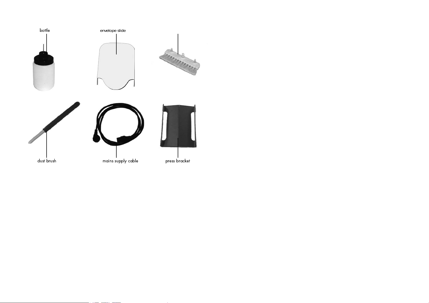
bottle
dust brush mains supply cable press bracket
envelope slide set brushes (3 pcs.)
Fig. 2
2.
2. HOW TO USE THE OPERATOR MANUALS
HOW TO USE THE OPERATOR MANUALS
2.2.
HOW TO USE THE OPERATOR MANUALSHOW TO USE THE OPERATOR MANUALS
This manual, existing of two parts, describes the
inserter (IN-3) module and operating (part 1: operator
manual) and programming of the system (part 2: guide for
job menu).
Use the 6900 Series manual as the main guide. In the text of this
manual we will refer to the other operator manuals if
required.
3.
3. ACCESSORIES
ACCESSORIES
3.3.
ACCESSORIESACCESSORIES
The IN-3 is delivered with the accessories shown in Fig. 2.
3/40
3/40
3/403/40
Page 5
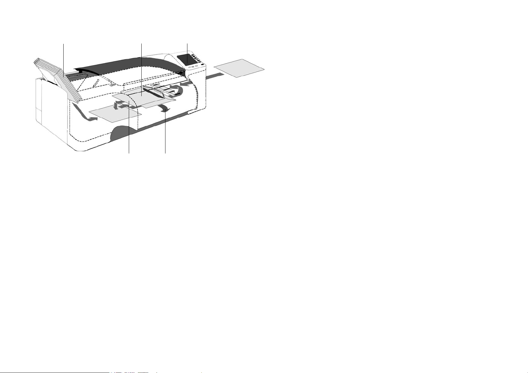
envelope hopper insert position user interface
sealing area exit
4.
4. UNDERSTANDING THE MACHINE
UNDERSTANDING THE MACHINE
4.4.
UNDERSTANDING THE MACHINEUNDERSTANDING THE MACHINE
4.1
4.1 Function
Function
4.14.1
Function Function
4.3
4.3 User interface
User interface
4.34.3
User interface User interface
The user interface of the inserter exists of two menus; the
"main menu" and the "job" menu. These menus are
The inserter inserts documents into envelopes and then seals
the envelopes (or not). Via the central operator panel the
6900 Series system can be operated and programmed.
Settings of a
4.2
4.2 Overview
4.24.2
ll modules are stored centrally at the inserter.
Overview
Overview Overview
See Fig. 3 .
Envelopes are fed from a stack to the insert position. During
this transport the flap is opened. After the envelope has
arrived at the insert position a document is fed to the inserter
and then inserted into the envelope. After insertion, the
envelope flap is moistened (or not) and closed. Then the
envelope is exited.
accessible via a personal pin code.
• The "main" menu is accessible for all operating personnel
and the supervisor. In the main menu jobs can be selected
and performed. After selecting a particular job, all
modules will be set automatically according the job data.
• The "job" menu is only accessible by an authorized user,
the "supervisor", via the supervisor pin code. In the job
menu jobs can be programmed, deleted etc. In a job the
settings of the modules within the system (type of
envelopes, type of documents, type of fold and way to
sort) are recorded. There are more functions in the job
menu. For a description of the job menu see the “Guide
for job menu”.
Fig. 3
The service engineer has access to all menus.
The system can be started, stopped or cleared by pressing
the concerned key located below the display of the inserter,
see section 4.6 page 6.
When a stoppage occurs, the IN-3 operator panel
automatically signals the operator and gives a suggestion
about solving the problem. See chapter 7 and 8.
4/40
4/404/40
Page 6
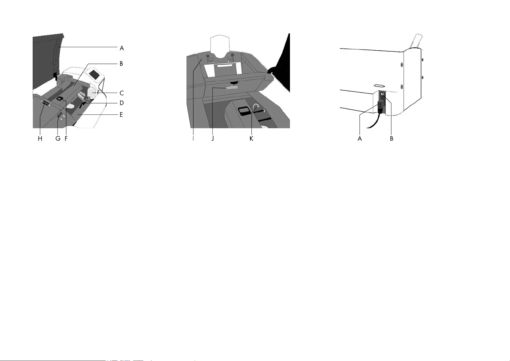
Fig. 4
Fig. 5
Fig. 6
4.4
4.4 Operating controls
Operating controls
4.44.4
Operating controls Operating controls
A: Top cover
B: Loc
C: Bottle
D : Release handle sealing table
E : Sealing table
F : Release handle loc
G: Hopper side guide adjustment wheel
H : Separation adjustment wheel
I : Envelope hopper
J : Release handle hopper
K : Release handle sealing table rollers
4.5
4.5 Power inlet
Power inlet
4.54.5
Power inlet Power inlet
See Fig. 6 . The power inlet B is located at the rear side of
the machine. It contains the power on/off switch and the
main fuse.
See "Warnings", page 2. Connect the main supply cable A
to the power inlet then connect the mains plug to the wall
socket.
5/40
5/40
5/405/40
Page 7
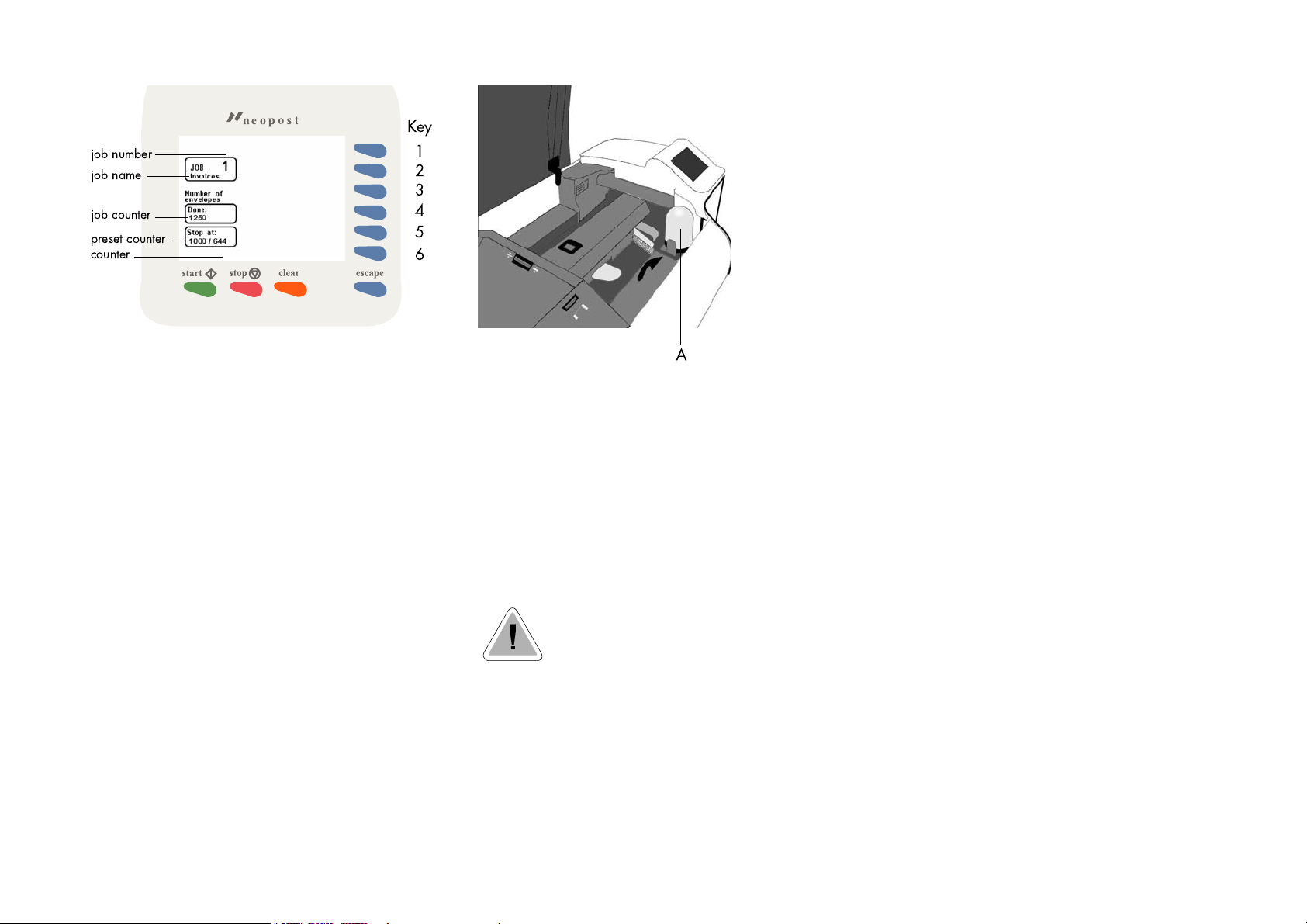
job number
job name
job counter
preset counter
counter
Key
1
2
3
4
5
6
Fig. 7
4.6
4.6 Display keys
Display keys
4.64.6
Display keys Display keys
Key 1 through 6
Key 1 through 6
Key 1 through 6Key 1 through 6
See Fig. 7 . These keys correspond with the function in the
display.
Start key
Start key
Start keyStart key
The system will start to operate.
For more details see 6.2 on page 22.
Stop key
Stop key
Stop keyStop key
The system will stop operating.
Clear key
Clear key
Clear keyClear key
The system will first finish all documents sets that have
already been fed (e.g. to the transport track) by the feed
units, then it stops.
Esc. key
Esc. key
Esc. keyEsc. key
Use this key to exit a (sub) menu without saving any
(altered) settings.
Fig. 8
5.
5. OPERATING THE SYSTEM
OPERATING THE SYSTEM
5.5.
OPERATING THE SYSTEMOPERATING THE SYSTEM
5.1
5.1 Preparations inserter module
Preparations inserter module
5.15.1
Preparations inserter module Preparations inserter module
The bottle A (Fig. 8) must always be filled with water and
the brushes must be moistened. An extra set of brushes is
provided so that one set can be soaked in water whilst the
other set is used. This means there is always a clean set of
brushes ready for usage.
Before moving the system, the bottle and
watertray must be removed.
Refer to the other operator manuals of the used modules for
the required preparations.
If the system is switched off after, for example, a paper
stoppage, the brushes will not rest on the watertray. This
causes the brushes to dry if usage is interrupted for a longer
period.
Always take care that the brushes rest on the watertray.
Therefore the system must be switched on again so that the
brushes will rest on the watertray. The system can then be
switched off.
6/40
6/40
6/406/40
Page 8

Key
1
2
3
4
5
6
Key
1
2
3
4
5
6
Fig. 9
5.2
5.2 Switching on
Switching on
5.25.2
Switching on Switching on
Switch on the inserter using the power switch A, see Fig. 9.
If the AS-1A, PS-3 or franking machine etc. are part of the
system switch these on. Refer to the operator manuals of the
used modules if necessary.
After switching on the pin code screen or the main menu will
appear. In case the pin code screen appears, see section
5.3 for further instructions. In case the main menu screen
appears, see section 5.4 for further instructions.
Fig. 10
5.3
5.3 Entering the personal pin code
Entering the personal pin code
5.35.3
Entering the personal pin code Entering the personal pin code
In Fig. 10 the pin code screen is shown.
Enter your pincode using the keys 1 to 6. If the code is not
correct, a warning “wrong code, try again” will be
displayed. This warning disappears immediately when a
key is pressed.
The pincode screen is not displayed if only the supervisor
code is defined. In this case the main menu as shown in Fig.
11 will be displayed after switching on the system.
5.4
5.4 The main menu
The main menu
5.45.4
The main menu The main menu
The main menu is shown in Fig. 11.
The "main menu" shows 6 different functions:
• go to job info screen (key 1).
• go to the "select job" menu (key 2).
• go to the "test run" menu (key 3).
• go to the "change counters" menu (key 4).
• go to the "settings"menu (key 5).
• go to the "entry to the job menu" (key 6).
Fig. 11
7/40
7/40
7/407/40
Page 9
Key
1
2
3
4
5
6
Key
1
2
3
4
5
6
Key
1
2
3
4
5
6
Fig. 12
5.4.1
5.4.1 Job info screen overview
5.4.15.4.1
Job info screen overview
Job info screen overview Job info screen overview
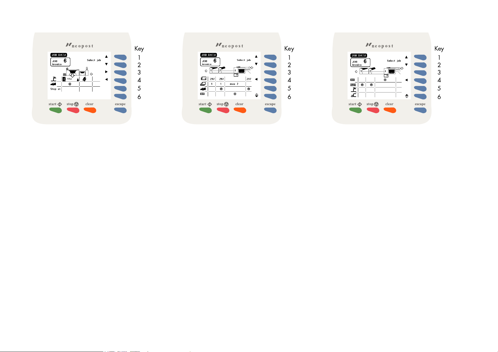
When key 1 is pressed in the “main menu”, the job info
screen will be displayed (see Fig. 12). The job info screen
shows the following functions:
• select a higher job number (key 1).
• select a lower job number (key 2).
• go to the job data of the upstream (transport) module (key
3).
• go to the job data of the downstream (sorting) module
(key 4) (the job data of the downstream (sorting) module
is shown in Fig. 15).
Press the escape key to go back to the main menu.
Because of the modularity of the system, different
configurations are possible. So take in account that the job
data can differ from which is shown in this job info screen
overview.
Fig. 13
When key 3 is pressed in the “job data” menu the upstream
(transport) module screen is displayed (see Fig. 13). The
screen shows the following functions:
• select a higher job number (key 1).
• select a lower job number (key 2).
• go back to the inserting module (key 4).
• go to next job data screen of the upstream (transport)
module (key 6).
Press the escape key to go back to the main menu.
Fig. 14
When key 6 is pressed in the upstream (transport) module
screen, the screen in Fig. 14 is displayed. The screen shows
the following functions:
• select a higher job number (key 1).
• select a lower job number (key 2).
• go back to the inserting module (key 4).
• go to previous job data screen of the upstream (transport)
module (key 6).
Press the escape key to go back to the main menu.
8/40
Page 10

Key
1
2
3
4
5
6
Fig. 15
When key 4 is pressed in the “job data” menu the
downstream (sorting) module screen is displayed (see Fig.
15). The screen shows the following functions:
• select a higher job number (key 1).
• select a lower job number (key 2).
• go back to the inserter module (key 3).
Press the escape key to go back to the main menu.
9/40
9/409/40
Page 11
5.4.2
5.4.2 Schematic view
5.4.25.4.2
Schematic view
Schematic view Schematic view
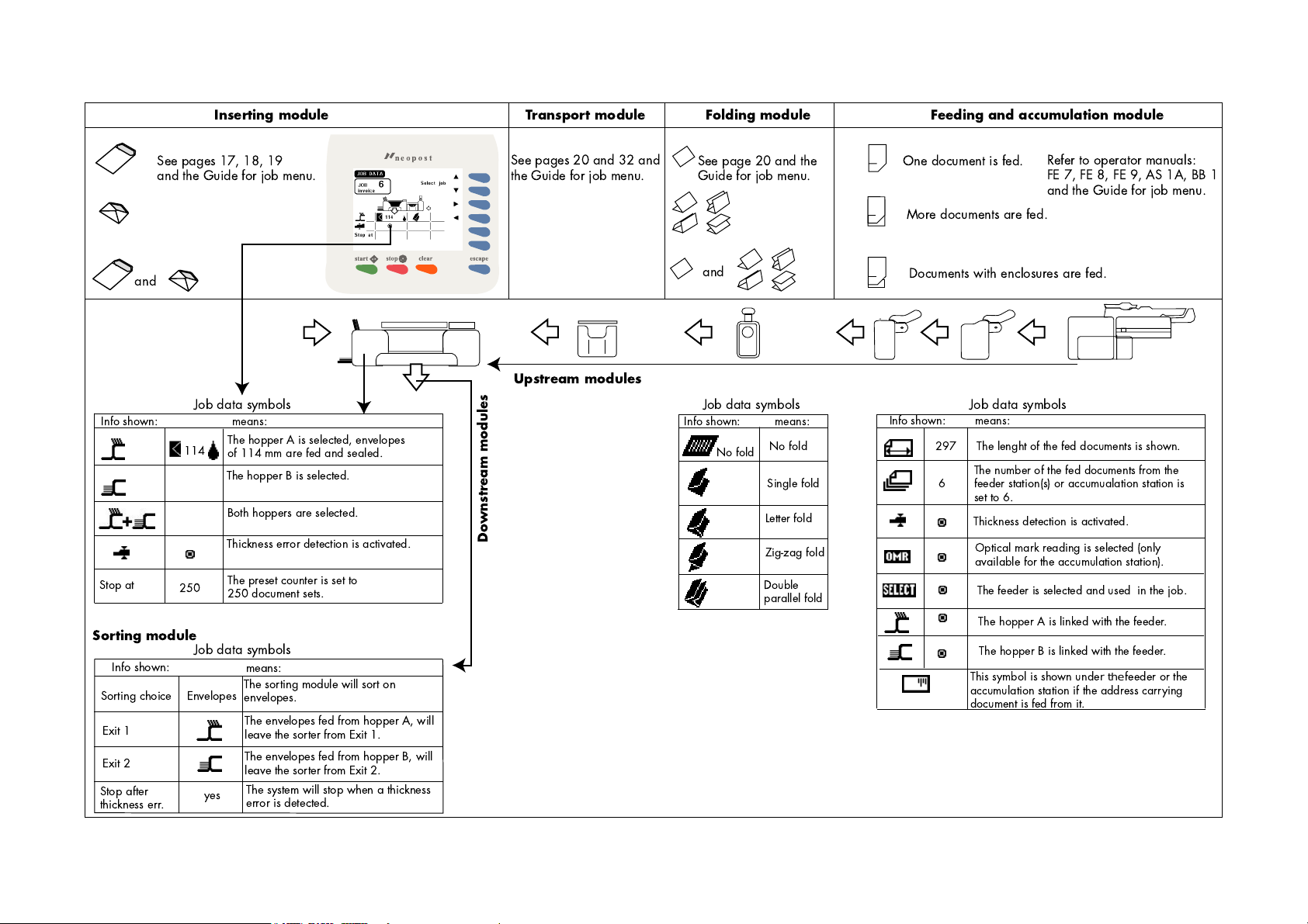
Inserting module Folding module Feeding and accumulation module
Transport module
See pages 17, 18, 19
and the Guide for job menu.
and
Info shown:
Stop at
250
Sorting module
Info shown:
Sorting choice
Exit 1
Exit 2
Stop after
thickness err.
See pages 20 and 32 and
the Guide for job menu.
See page 20 and the
Guide for job menu.
One document is fed.
More documents are fed.
and
Documents with enclosures are fed.
Upstream modules
Job data symbols Job data symbols Job data symbols
means:
The hopper A is selected, envelopes
114
of 114 mm are fed and sealed.
The hopper B is selected.
Both hoppers are selected.
Thickness error detection is activated.
The preset counter is set to
250 document sets.
Job data symbols
means:
Envelopes
The sorting module will sort on
envelopes.
The envelopes fed from hopper A, will
leave the sorter from Exit 1.
The envelopes fed from hopper B, will
leave the sorter from Exit 2.
The system will stop when a thickness
yes
error is detected.
Downstream modules
Info shown:
No fold
means:
No fold
Single fold
Letter fold
Zig-zag fold
Double
parallel fold
Info shown:
means:
The lenght of the fed documents is shown.
297
The number of the fed documents from the
6
feeder station(s) or accumualation station is
set to 6.
Thickness detection is activated.
Optical mark reading is selected (only
available for the accumulation station).
The feeder is selected and used in the job.
The hopper A is linked with the feeder.
The hopper B is linked with the feeder.
Thissymbolisshownunde
accumulation station if the address carrying
document is fed from it.
Refer to operator manuals:
FE 7, FE 8, FE 9, AS 1A, BB 1
and the Guide for job menu.
rthe
feederorthe
10/40
10/4
10/4010/40
Page 12
Key
1
2
3
4
5
6
Key
1
2
3
4
5
6
Fig. 16
5.4.3
5.4.3 Selecting a job
5.4.35.4.3
Selecting a job
Selecting a job Selecting a job
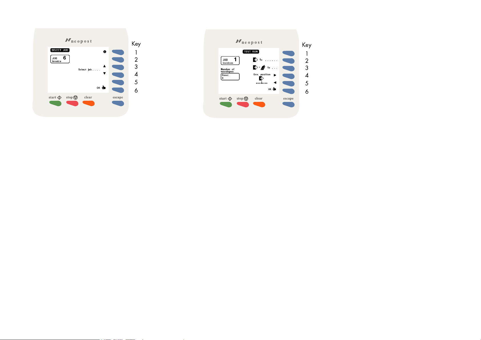
After pressing key 2 in the "main menu", the display shows
the "select job" menu (see Fig. 16). The "select job" menu
shows the following functions:
• job data (key 1).
• select a higher job number (key 3).
• select a lower job number (key 4).
• confirm with "OK" (key 6) which will get you back to the
"main menu".
Only programmed jobs can be selected (maximum of 9
jobs).
Fig. 17
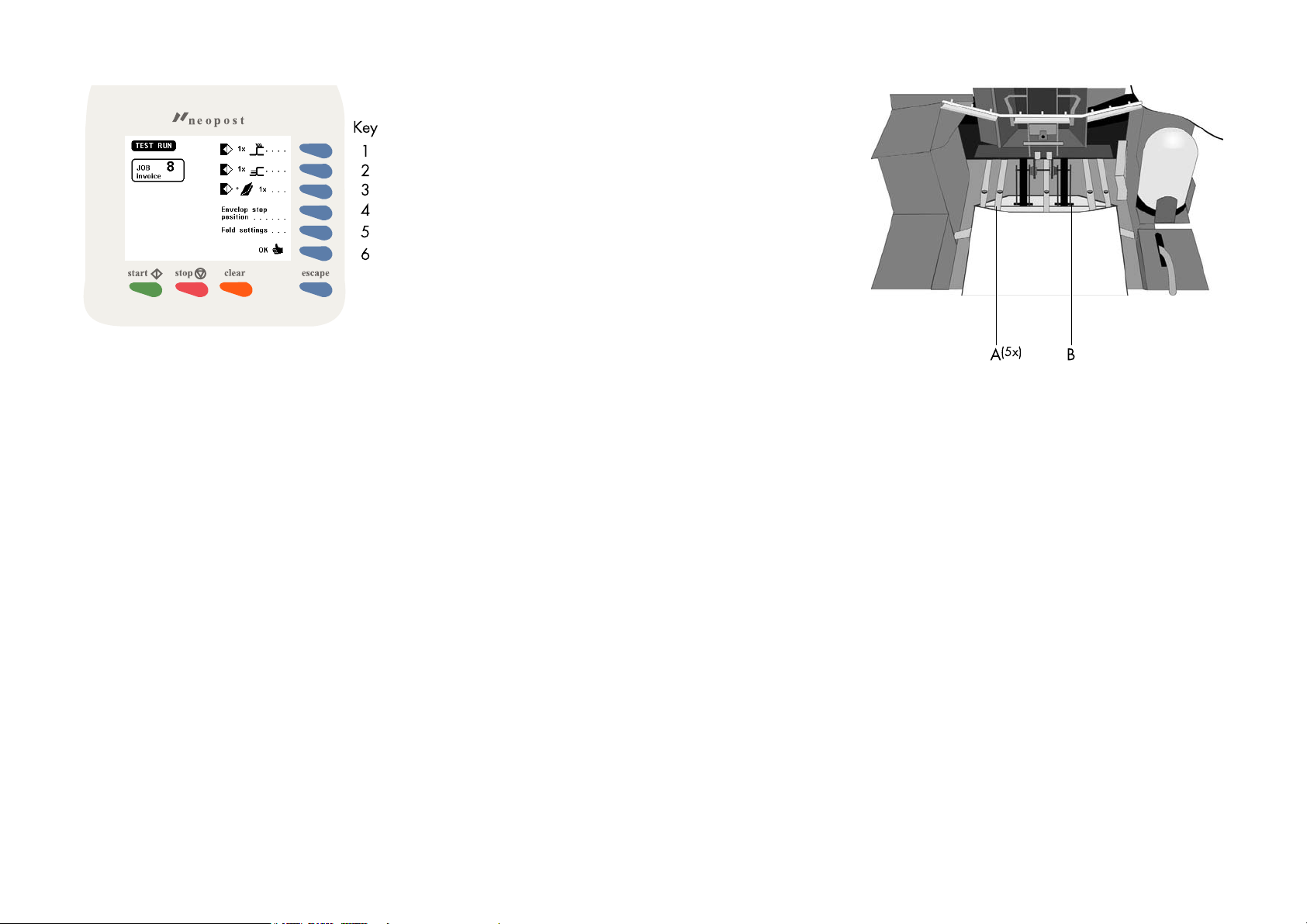
5.4.4
5.4.4 Test run menu
5.4.45.4.4
Test run menu
Test run menu Test run menu
After pressing key 3 in the "main menu" a test run screen will
be displayed. In case an FO-2A is used the screen as
shown in fig. 17 will appear. The purpose of the test run
menu is to check proper envelope feed and to make
adjustments to the envelope stop settings.
The "test run" menu shows the following functions:
• feed one envelope (key 2).
• insert one document (key 3).
• envelope stop position to the right (key 4).
• envelope stop position to the left (key 5).
• confirm settings and return to the main menu (key 6).
In case an FO-3 is used, a screen as shown in fig. 18 will be
displayed. The envelope position keys 4 and 5 of figure 17
have moved to a new submenu (see fig. 18, key 4): after
pressing key 4 this submenu will be entered and the
possibility of adjusting the envelope stop position to the left
or right is available again.
After pressing key 5 a submenu will be entered for fine
tuning the folder settings. For more information see "Fine
tuning the folder settings".
In case the inserter is equipped with a second envelope
hopper (EF-3) the test run menu has been extended and the
following functions for key 1 and 2 have become available
(see fig. 18 for an example):
•
feed one envelope from the standard hopper (key 1).
•
feed one envelope from the second hopper EF-3 (key 2).
11/40
11/40
11/4011/40
Page 13
Feed one envelope
Feed one envelope
Feed one envelope Feed one envelope
Key
1
2
3
4
5
6
Fig. 18
Insert one document
Insert one document
Insert one document Insert one document
(5x)
Envelope stop position adjustment
Envelope stop position adjustment
Envelope stop position adjustment Envelope stop position adjustment
Fig. 19
With this function the proper feed of envelopes can be
tested. First carry out the envelope hopper adjustments, see
section 5.7 on page 17. Then put a stack of envelopes in
the hopper. Use key 1 or key 2 to feed one envelope onto
the insert table. Each time the key is pressed a new
envelope will be fed. No insertion will take place.
The “feed one envelope” function can be used when
adjusting the envelope stop position, see “Envelope stop
position adjustment” on the next page.
12/40
12/40
12/4012/40
With this function the proper functioning of the whole
document and envelope transport will be tested. First carry
out all adjustments, see section 5.7 on page 17. Then load
the system with documents and envelopes.
Use key 3 to make one insert cycle. Each time the key is
pressed another insert cycle will be made. When there is no
envelope waiting on the insert table, the machine feeds one
envelope waiting on the insert table. The document will be
inserted and filled envelope is ejected.
If there are documents on the collating area, these
documents will be inserted and the filled envelope is ejected
(and counted). If there is an empty envelope in the inserter,
this envelope will be ejected.
See notes mentioned in section 6.2 on page 22.
The flap folding line must be positioned under the green
indicator B (Fig. 19). This indicator can be seen after
opening the transparent cover and releasing and lifting the
loc by pulling the release handle of the loc (see page 5).
If necessary, adjust the folding line position by pressing “to
the right” (key 4) or the “to the left” (key 5). Each press
stops the next envelope 1 mm (0,04 inch) to the right (later)
or left (earlier).
Adjustments to the envelope stop position can be made with
the system operating.
Page 14

Envelope fingers adjustment
Envelope fingers adjustment
Envelope fingers adjustment Envelope fingers adjustment
When the envelope stop position is correct the insert fingers
A (Fig. 19) can be adjusted. Adjust the fingers by loosening
the thumb screw on top of each finger (5 in total). Slide the
finger until the tip has entered about 5 mm (0,2 inch) into
the envelope. Re- tighten the screw. The fingers on either
side of the loc can be moved sideways to the desired
position. Place the outer fingers about 10 mm (0,4 inch)
from the edges of the envelope.
Check the finger positions when changing to a different type
of envelope.
Key
1
2
3
4
5
6
Fig. 20
Fine tuning the folder settings
Fine tuning the folder settings
Fine tuning the folder settings Fine tuning the folder settings
In the 6900 Series, if and when the electronic folder FO-3 is used,
the operator has the possibility to adjust the (mechanical) folder
settings during the execution of a specific job. This might be
neccesary for instance when adapting the fold settings to
the current mechanical paper parameters (thickness,
sturdiness et cetera).
After pressing key 5 in figure 18 the menu of figure 20
appears.
The following functions are available:
• test for a folded document 1x (key 1). It makes sense to
do this in the same menu screen.
• Increase/ decrease value of fold setting A (keys 2 and
3). Basically there is no limitation in the values. The
possibilities are same as in the equivalent settings of the
job menu (FO settings).
• as keys 2 and 3, for fold setting B, if relevant (keys 4 and
5). This depends on the fold type. Setting B is relevant for
all fold types except single fold. Note that you cannot
change the fold type in this menu.
• enter and effectuate the settings (key 6). Back to the menu
"test run" menu of figure 18.
• discard the settings (Esc). Back to the "test run" menu of
figure 18.
13/40
13/40
13/4013/40
Page 15

Key
1
2
3
4
5
6
Key
1
2
3
4
5
6
Fig. 21
5.4.5
5.4.5 Counters menu
5.4.55.4.5
Counters menu
Counters menu Counters menu
After pressing key 4 in the "main menu", the display shows
the "change counters" menu (Fig. 21). The "change
counters" menu shows the following functions:
• increase the counters (key 1).
• decrease the counters (key 2).
• reset counters to zero (key 3).
• increase the preset counters (key 4).
• decrease the preset counters (key 5).
• save the counter settings with "OK" (key 6) which will get
you back to the "main menu".
Increase/decrease counters
Increase/decrease counters
Increase/decrease counters Increase/decrease counters
The following counters will be increased or decreased:
•job counter.
•counter.
Reset counters to zero
Reset counters to zero
Reset counters to zero Reset counters to zero
The following counters will be set to zero:
•job counter.
•counter.
Increase and decrease preset counter
Increase and decrease preset counter
Increase and decrease preset counter Increase and decrease preset counter
By pressing key 4 or key 5 the preset counter will be
increased or decreased.
The counter will only be displayed when the preset counter
is set higher than zero.
When pressing key 4 or key 5, the stop counter will initially
be increased or decreased with one unit at a time. When
the key is pressed longer the counter will be raised with ten
units at a time.
Fig. 22
5.4.6
5.4.6 Settings menu
5.4.65.4.6
Settings menu
Settings menu Settings menu
After pressing key 5 in the “main menu”, the screen as
shown in Fig. 22 will be displayed. The “settings” menu
shows the following functions:
• job data (key 1).
• decrease contrast of the display (key 2).
• increase contrast of the display (key 3).
• thickness detection on or off (key 4).
• reset thickness detection (key 5).
• save the counter settings with "OK" (key 6) which will get
you back to the "main menu".
Display contrast
Display contrast
Display contrast Display contrast
By pressing key 2 the display contrast will be decreased. By
pressing key 3 the display contrast will be increased.
14/40
14/4014/40
Page 16

Thickness detection
Thickness detection
Thickness detection Thickness detection
Reset thickness detection
Reset thickness detection
Reset thickness detection Reset thickness detection
5.5
5.5 Entry to job menu
Entry to job menu
5.55.5
Entry to job menu Entry to job menu
Key
1
2
3
4
5
6
Fig. 23
The IN-3 is equipped with a document thickness detector.
The thickness detector controls the thickness of the
document. In this way the machine checks if the envelope
will be filled with the correct amount of documents. The
detector will stop the machine if a document is too thick or
too thin and an error message will be displayed.
The thickness detector is self-setting. After switching on (or
after resetting the thickness detection) the thickness of the
first document passing under the detector is memorized and
compared with the following inserts.
If the thickness of the documents can vary, for example
when a small card is used that can shift in place, it is
recommended to switch off the thickness detection or shift it
to a stable section of the document. The thickness detection
measurement area can only be adjusted by the supervisor.
See section 2.4.3 in the “Guide for job menu”.
By pressing key 5 the thickness detection will be reset.
If the thickness detection is switched off, the text “reset
thickness det.....” will not be displayed in the screen.
When key 6 in the “main menu” is pressed the display
shows the screen in Fig. 23. Only the supervisor can get
access to the job settings after entering the correct code.
Enter your pincode using the keys 1 to 6. If the code is not
correct, a warning “wrong code, try again” will be
displayed. This warning disappears immediately when a
key is pressed.
15/40
15/40
15/4015/40
Page 17

5.6
5.6 Operator menu structure
Operator menu structure
5.65.6
Operator menu structure Operator menu structure
Key
Start key
Start processing
Stop key
Stop processing
Clear key
Empty the system and stop
Escape key
Exit a menu without saving any
altered settings
Select a job number for job
data, see page 8
Select (upstream) transport module data
Select (downstream) sorter module data
1
2
3
4
5
6
Job data, page 8
Select a job
Confirm selected job and go to main menu
Feed one envelope from hopper A, page 12
Feed one envelope from hopper B
Insert one document
Envelope stop position to the right
Envelope stop position to the left
Confirm settings and back to main menu
Increase counters, page 14
Decrease counters
Reset counters to zero
Increase preset counter
Decrease preset counter
Confirm settings and back to main menu
Job data, page 8Enter pincode, page 15
Adjust display contrast, page14
Select thickness detection on or off
Reset thickness detection
Confirm settings and back to main menu
16/40
16/4016/40
Page 18

5.7
5.7 Envelope hopper adjustment
Envelope hopper adjustment
5.75.7
Envelope hopper adjustment Envelope hopper adjustment
Fig. 24
5.7.1
5.7.1 Side guides adjustment hopper A
5.7.15.7.1
Side guides adjustment hopper A
Side guides adjustment hopper A Side guides adjustment hopper A
Fig. 25
5.7.2
5.7.2 Envelope separation hopper A
5.7.25.7.2
Envelope separation hopper A
Envelope separation hopper A Envelope separation hopper A
The IN-3 can be equipped with a second hopper, the EF-3
(see section 10.2 page 32). This hopper is then called
“hopper B”. The IN-3 standard hopper is called “hopper
A”. Although an operator manual is delivered with the EF-3,
on this page you will also find a description of the hopper
adjustments.
Take a stack of about 20 envelopes. Fan the envelopes a bit
(see Fig. 24) and place the envelopes upright in the system
with the flap to the back. Place the press bracket C on the
envelopes.
Adjust the envelope hopper side guides B by turning the
thumbwheel A, to provide just enough space for the
envelopes to move freely. Too much play causes skewing.
When using C4 envelopes check if the blade spring on the
sealing table is up. The spring is visible after lifting the loc.
The purpose of the spring blade is to obtain better support
when using thin A4 sized documents.
Adjust the envelope separation by turning thumbwheel D
(see Fig. 25) until one envelope is just about to be pulled in.
After starting the system it may occur that more than one
envelope at a time is pulled in. If this happens, rotate the
thumbwheel slightly until only one envelope at a time is
pulled in. Adjustments can be made with the system
operating.
17/40
17/40
17/4017/40
Page 19

5.7.3
5.7.3 Side guides hopper B
5.7.35.7.3
Side guides hopper B
Side guides hopper B Side guides hopper B
Fig. 26
5.7.4
5.7.4 Envelope separation hopper B
5.7.45.7.4
Envelope separation hopper B
Envelope separation hopper B Envelope separation hopper B
Take a stack of about 20 envelopes. Fan the envelopes a bit
and place the envelopes in the system with the flap to the
bottom side and trailing.
Adjust the envelope hopper side guides A (Fig. 26) by
turning the thumbwheel C, to provide just enough space for
the envelopes to move freely. Too much play causes
skewing.
18/40
18/4018/40
Adjust the envelope separation by turning knob B (Fig. 26)
counter clockwise until two envelopes, one on top of the
other, can be moved backwards and forwards between the
rollers without resistance. Then turn knob B clockwise until
one envelope will pass between the rollers.
After starting the system it may occur that more than one
envelope at a time is pulled in. If this happens, rotate knob B
clockwise a quarter turn. Repeat if necessary to obtain
correct operation.
Once the envelope separation has been set, a wide variety
of envelopes can be handled.
Page 20

6.
6. PERFORMING A JOB
PERFORMING A JOB
6.6.
PERFORMING A JOBPERFORMING A JOB
6.1
6.1 Setting up the system
Setting up the system
6.16.1
Setting up the system Setting up the system
Switch on the inserter IN-3 and, if part of the system, the AS-1A and PS-3 etc.
Refer to the operator manuals of the used modules.
Inserter IN-3
Inserter IN-3
Inserter IN-3 Inserter IN-3
Action
Action Refer to..
ActionAction
• Check the waterlevel, refill if necessary Refer to section 5.1 Preparations inserter module on page 6
• If required, enter pincode to gain access to the main menu Refer to section 5.3 Entering the personal pin code on page 7
Refer to..
Refer to..Refer to..
• Select the required job
To recognize the correct job number, all jobs should have been given names. If so, the name is visible in the
framework under JOB X.
• Press the Job info key. Use the job info facility as a guide to put the envelopes at the correct enve-
lope hoppers and the documents at the correct feed stations.
• After the correct job has been selected press the OK key to confirm. Now the job information will
be sent to all modules.
• Set the envelope hopper side guides and separation Refer to section 5.7 Envelope hopper adjustment on page 17
• Enter the test menu, press the 1x envelope key to bring an envelope onto the insert table.
• Check the envelope stop position, adjust if necessary.
• Set the envelope fingers
• If necessary, enter the counters menu to change or reset the counters. Refer to section 5.4.5 Counters menu on page 14
• If necessary, enter the settings menu to check the thickness detector settings. Refer to section 5.4.6 Settings menu on page 14
Refer to section 5.4.3 Selecting a job on page 11
Refer to section 5.4.1 Job info screen overview on page 8
Refer to section 5.4.3 Selecting a job on page 11
Refer to section 5.4.4 Test run menu on page 11
19/40
19/40
19/4019/40
Page 21

Transport unit TR-7A, TR-1B
Transport unit TR-7A, TR-1B
Transport unit TR-7A, TR-1B Transport unit TR-7A, TR-1B
Action
Action Refer to..
ActionAction
Refer to the operator manuals of these modules if required.
Refer to..
Refer to..Refer to..
• If necessary adjust the module TR-7A.
Note 1: With the 6900 Series selection of a mode at the TR-7A is not applicable.
Note 2: Information about where to put the address carrying documents and the enclosures can be
found in the job info menu of the inserter.
Note 3: It is possible that there is no TR-7A fold/no fold selector available. In that case the TR-7A is
equipped with so called Twin cycle facility that automizes this setting (see options).
• If necessary adjust the module TR-1B. Refer to the chapter “Adjustments” and follow the instructions.
Fold unit FO-3, FO-2A
Fold unit FO-3, FO-2A
Fold unit FO-3, FO-2A Fold unit FO-3, FO-2A
Action
Action Refer to..
ActionAction
Refer to the operator manuals of these modules if required.
• For the FO-3 no adjustments have to be made. -
• The fold unit has to be set such that the folded documents fit in to the envelope. Refer to the chapter “Adjustments” and follow the instructions.
Feed stations FE-1M, FE-8, FE-7, FE-9, ST-1, PF-45A, PF-65A, SF-4/6
Feed stations FE-1M, FE-8, FE-7, FE-9, ST-1, PF-45A, PF-65A, SF-4/6
Feed stations FE-1M, FE-8, FE-7, FE-9, ST-1, PF-45A, PF-65A, SF-4/6 Feed stations FE-1M, FE-8, FE-7, FE-9, ST-1, PF-45A, PF-65A, SF-4/6
Action
Action Refer to..
ActionAction
Refer to the operator manuals of these modules if required.
• If necessary adjust the modules FE-7, FE-8, ST-1, PF-45A, PF-65A. Refer to the chapter “Adjustments” and follow the instructions.
Refer to the chapter “Adjustments” and follow the instructions.
Refer to..
Refer to..Refer to..
Refer to..
Refer to..Refer to..
• If necessary adjust the module FE-9. Refer to the chapter “Settings” and follow the instructions.
• If necessary adjust the module FE-1M. Set the document hopper guides and the separation.
• Fill the hoppers of the feed units with documents. Refer to the operator manuals of the feed units.
20/40
20/4020/40
Refer to the sections “Side guide adjustment” and “Separation
adjustment”.
Page 22

AS-1A
AS-1A
AS-1A AS-1A
Action
Action Refer to..
ActionAction
Refer to the operator manuals of these module if required.
• If necessary adjust the module AS-1A. Refer to the chapter “Adjustments” and follow the instructions.
3d Party device
3d Party device
3d Party device 3d Party device
Action
Action Refer to..
ActionAction
Refer to the operator manuals of these modules if required.
Refer to..
Refer to..Refer to..
Refer to..
Refer to..Refer to..
21/40
21/40
21/4021/40
Page 23

Key
1
2
3
4
5
6
Fig. 27
6.2
6.2 Running a job
Running a job
6.26.2
Running a job Running a job
Start
Start
StartStart
Test cycle
After all settings have been carried out a few test cycles can
be made by using the "insert one document" function, see
section 5.4.4 page 12 or see fig 27.
Automatic operation
When correct insertion is obtained, start automatic
operation by pressing the "Start" key.
When the “start” key is pressed (after switching on and no
other job is selected), the job information is sent to all
machines in the system. During this time an egg timer will
appear for about 10 seconds. When ready, the system
starts operating.
If documents from a previous job are detected on the
transport track (TR-7A), these are transported to the
collating area of the TR-7A. The system then stops and
indicates that these documents have to be removed.
Remove and press the start key again.
Stop
Stop
Stop Stop
Press the stop key to stop the system.
Job finishing
Job finishing
Job finishingJob finishing
The system can be cleared during the running of a job or
after running out of address carrying documents.
To clear the system, press the clear key. The system will finish
all documents sets that have already been fed (e.g. to the
transport track) by the feed units. Then the system stops.
In case a transport unit is part of the system, see TR-7A
operator manual chapter 6.
With the 6900 Series, use the inserter clear key instead of
using the TR-7A reset key.
With the 6900 Series, remarks about the inserter "pause"key
are not applicable.
Stoppages
Stoppages
StoppagesStoppages
In case of a stoppage, refer to chapter 7 and 8.
22/40
22/4022/40
Page 24

6.3
6.3 Changing settings of a module
Changing settings of a module
6.36.3
Changing settings of a module Changing settings of a module
The settings of feed modules including the AS-1A are stored
in jobs. To provide extra flexibility, it is possible to change
the settings on a module locally (after selecting the job). In
this way it is possible to run different applications using just
one job.
These changes will not be memorized and are lost after
selecting another job or switching off the system.
Below the possible changes in settings are listed:
• all feed modules including AS-1A can be switched on or
off.
• at the FE-7, FE-9 and ST-1 the double document detector
can be switched on or off. Also the value of the multifeed
counter can be changed.
• at FE-8 changes in the "set" menu can be made.
• at the AS-1A all settings mentioned in chapter 4 can be
changed.
6.4
6.4 Additional functions
Additional functions
6.46.4
Additional functions Additional functions
The 6900 Series provides additional operating functions.
They are listed below:
AS-1A
AS-1A
AS-1AAS-1A
• The AS-1A can be locally switched on or off (toggle
function). To switch on or off, press and hold the “Pause”
key for one second. The AS-1A display shows an “u”
when switched off. This “u” is also visible when the AS-1A
is switched off by the IN-3.
• Extra functionality Automix
SF/FS interface box
SF/FS interface box
SF/FS interface boxSF/FS interface box
TM
", see chapter 10.
• The SF/FS interface box (used with crossfold applications
or foot switch) can be locally switched on or off. To switch
the interface box on or off, press and hold the blue reset
key (toggle function) for one second. When switched on,
a yellow (on the interface box) lamp will light.
23/40
23/40
23/4023/40
Page 25

Options
Options
Options Options
7.
7. FAULT FINDING
FAULT FINDING
7.7.
FAULT FINDINGFAULT FINDING
7.1.1
7.1.1 The error screen
7.1.17.1.1
The error screen
The error screen The error screen
Key
1
2
3
4
5
6
Fig. 28
See chapter 10.
24/40
24/4024/40
7.1
7.1 General
General
7.17.1
General General
The IN-3 detects the following error types:
• errors in the paperflow.
• technical errors.
• changes in configuration.
When an error (for example running out of envelopes) is
about to occur a warning screen is displayed.
The error screen (an example is shown in Fig. 28) provides
the following information:
• the error location, indicated by an arrow in the machine
symbol (C).
• the error description (A).
• the suggested solution (B).
Resetting the machine
Resetting the machine
Resetting the machine Resetting the machine
After solving the problem the machine can be reset by
pressing key 6. The error screen will disappear.
Page 26

Key
1
2
3
4
5
6
Key
1
2
3
4
5
6
Fig. 29
7.1.2
7.1.2 The information screen
7.1.27.1.2
The information screen
The information screen The information screen
By pressing key 1 in the error screen, an additional
information screen as shown in Fig. 29 is displayed.
This screen shows more information about the cause of the
error. In this screen also the error code of the error is
displayed. For a complete description of the error codes
chapter 8.
7.1.3
7.1.3 The warning screen
7.1.37.1.3
The warning screen
The warning screen The warning screen
A warning screen is displayed when a refill is necessary. An
example of a message screen is shown in Fig. 30.
Resetting the machine
Resetting the machine
Resetting the machine Resetting the machine
After refilling, the machine can be reset by pressing key 6.
The message screen will disappear.
Fig. 30
Configuration message
Configuration message
Configuration message Configuration message
The following message can occur if a job is selected in the
“job edit” menu:
“System differs from job data. Not corresponding modules
need to be set”.
When selecting a job, the system checks the current device
configuration with the device configuration as stored in the
job.
The operator can either ignore the message and continue
(soft key 6) or cancel the job editing.
This message is not displayed if the replaced or removed
device is switched off for this job, or if the replaced or
removed device has no job settings (i.e. FO-2A or TR-1B
plus foot switch).
If an FO-2A is replaced by an FO-3, the following default
settings for the FO-3 will be used:
• Envelope length > document length A4 + 6 mm margin.
No fold.
• Envelope length > document length ½A4 + 6 mm margin.
Single fold with A = 149 mm.
• Envelope length > document length 1/3 A4 + 6 mm
margin. Letter fold with A = 97 mm and B = 197 mm.
• Envelope length < document length 1/3 A4 + 6 mm
margin. Double parallel fold with A = 200 mm and B =
100 mm.
If the envelope length isn't yet known, the default envelope
length is used.
25/40
25/40
25/4025/40
Page 27

Key
1
2
3
4
5
6
Fig. 31
7.1.4
7.1.4 The call screen
7.1.47.1.4
The call screen
The call screen The call screen
When a technical error occurs the error screen will not
display the machine symbol. Instead a message “Technical
error, call service” will be displayed (see Fig. 31).
This screen indicates that the occured error can not be
solved by operating personnel. Assistance of service
support is needed.
First write down the error code, than switch the inserter off
and on again, to verify system operation. When the error
still occurs contact your service organization.
7.2
7.2 Clearing stoppages
Clearing stoppages
7.27.2
Clearing stoppages Clearing stoppages
When an error in the paperflow occurs, the machine can
give the following suggested solutions:
• remove the document(s).
• remove the envelope.
Fig. 32
7.2.1
7.2.1 Removing documents
7.2.17.2.1
Removing documents
Removing documents Removing documents
When an error occurs in the document feed the error screen
can show the following symbols:
stoppage in the document end feed.
stoppage in the document feed.
Fig. 33
7.2.2
7.2.2 Stoppage in the document end feed
7.2.27.2.2
Stoppage in the document end feed
Stoppage in the document end feed Stoppage in the document end feed
Remove documents in the following way:
• remove documents from the document feed end.
• press the reset key.
7.2.3
7.2.3 Stoppage at the document feed
7.2.37.2.3
Stoppage at the document feed
Stoppage at the document feed Stoppage at the document feed
Remove documents in the following way:
• lift the loc by pulling the release handle A of the loc (see
Fig. 32).
• remove the document.
• close the loc.
• press the reset key.
26/40
26/4026/40
Page 28

Fig. 34
7.2.4
7.2.4 Removing documents from the hopper
7.2.47.2.4
When an error occurs in the hopper the error screen shows
the following symbol:
The envelopes can be removed in the following way:
• remove all envelopes from the hopper.
• open the hopper by pulling release handle A of the
• remove the envelopes from the lower part of the hopper.
• close the hopper with a firm click.
• press the reset key.
Removing documents from the hopper
Removing documents from the hopper Removing documents from the hopper
stoppage in the hopper.
hopper upwards (see Fig. 33 and Fig. 34).
7.2.5
7.2.5 Removing envelopes from the insert or
7.2.57.2.5
When an error occurs in the inner part of the machine, the
error screen can show the following symbols:
Removing envelopes from the insert or
Removing envelopes from the insert or Removing envelopes from the insert or
sealing table
sealing table
sealing table sealing table
stoppage on the insert table.
stoppage on the sealing table.
stoppage in the envelope track.
7.2.6
7.2.6 Stoppage on the insert table or sealing table
7.2.67.2.6
Remove envelopes in the following way:
• lift the loc by pulling the release handle A of the loc (see
• remove the envelope.
• close the loc.
• press the reset key.
Stoppage on the insert table or sealing table
Stoppage on the insert table or sealing table Stoppage on the insert table or sealing table
Fig. 32).
27/40
27/40
27/4027/40
Page 29

7.2.7
7.2.7 Stoppage in the envelope track
7.2.77.2.7
Remove envelopes in the following way:
• lift the loc by pulling the release handle A of the loc (see
• lift the sealing table by pulling the locking handle B of the
• remove the envelope.
• close the sealing table and the loc.
• press the reset key.
28/40
28/4028/40
Stoppage in the envelope track
Stoppage in the envelope track Stoppage in the envelope track
Fig. 32).
sealing table.
Page 30

8.
8. ERROR CODES
ERROR CODES
8.8.
ERROR CODESERROR CODES
8.1
8.1 General
General
8.18.1
General General
The central display of the inserter will display all system-wide errors that occur. When an error occurs, read the information on the screen, press the info key for more information. Follow the
instructions. Generally an error number will be given. This number can be used for reference.
error description
error description suggested solution
error descriptionerror description
suggested solution see also....
suggested solutionsuggested solution
see also.... information
see also....see also....
information Error code
informationinformation
Error code
Error codeError code
Envelope stoppage. Remove envelope,
readjust the envelope separation.
Envelope stoppage. Remove envelope,
readjust the envelope separation.
Envelope stoppage. Remove envelope. Page 26. Envelope doesn’t reach the “track” sensor. 4
Envelope stoppage. Remove envelope. Page 26. Envelope doesn’t reach the “flap” sensor. 5
Envelope stoppage. Remove envelope. Page 26. Envelope not opened or already opened in the
Wrong envelope size or too many envelopes fed
Closed envelope ? Put an open envelope in the hopper. probably closed envelope in hopper. 8
Document stoppage. Remove document. Page 26. Document doesn’t reach the “input” sensor. 9
Document stoppage. Remove document. Page 26. Document doesn’t clear the “input” sensor. 10
Document stoppage. Remove document. Page 26. Insert failure: Document is not clearing the “loc” sen-
Not enough documents inserted Remove envelope and check contents,
To many documents inserted Remove envelope and check contents,
Remove envelope,
place the correct envelopes in the hopper.
reset thickness detection.
reset thickness detection.
Page 7.
Page 17.
Page 6.
Page 17.
Page 17.
Page 26.
Page 15
Page 26.
Page 15
Page 26.
Envelope longer than reference length.
Envelope doesn’t reach the “track” sensor.
envelope hopper.
Wrong envelope size or separation not correctly
adjusted. 7
sor.
Document too thin.
Document too thick.
11
12
13
1
3
6
Envelope stoppage. Remove envelope. Page 26. Document doesn’t clear the “eject” sensor. 14
Envelope stoppage. Remove envelope. Page 26. Document doesn’t reach the “exit” sensor. 15
Envelope stoppage. Remove envelope. Page 26. Document doesn’t clear the “exit” sensor. 16
29/40
29/40
29/4029/40
Page 31

error description
error description suggested solution
error descriptionerror description
suggested solution see also....
suggested solutionsuggested solution
see also.... information
see also....see also....
information Error code
informationinformation
Error code
Error codeError code
Unknown set. Remove set. Page 26. During the system startup a set has been detected.
Remove this set.
Configuration does not match. Switch the inserter off and restore the
configuration.
System can not be set. Select job again. The job settings can not be transmitted correctly.
8.2
8.2 Additions to the error lists of other modules
Additions to the error lists of other modules
8.28.2
Additions to the error lists of other modules Additions to the error lists of other modules
error description
error description suggested solution
error descriptionerror description
Document stoppage. Remove documents. The document (that has been delivered by the Side
Document stoppage. Remove documents. The document to be delivered by the Side Feed unit
Feeding failure. Remove documents. The Side Feed Unit (PF) is empty. Refill the document
System blocked. Remove envelope and check contents,
reset thickness detection.
suggested solution see also....
suggested solutionsuggested solution
see also.... information
see also....see also....
A module of the system has been removed.The configuration is not corresponding with the selected job.
Check if of all covers are closed.
information Error code
informationinformation
Feed unit) does not move during a TR-7A finger
cycle. Clear the paper jam.
does not reach the TR-7A track. Remove paper jam
and adjust arm height of the Side Feed unit.
hopper.
The fold unit (FO-2A, FO-3) is either not present or
not correctly placed (this is indicated by a
microswitch that blocks FO operation). Place or correctly place the fold unit.
62
67
68
Error code
Error codeError code
80
81
120
1
Document stoppage. Remove envelope and check contents,
reset thickness detection.
30/40
30/4030/40
The document does not reach the output of the
folder. This is likely caused by a paper jam in the
FO.
2
Page 32

9.
9. MAINTENANCE
MAINTENANCE
9.9.
MAINTENANCEMAINTENANCE
Fig. 35
9.2
9.2 General cleaning
General cleaning
9.29.2
General cleaning General cleaning
Fig. 36
9.4
9.4 Cleaning the sealing roller
Cleaning the sealing roller
9.49.4
Cleaning the sealing roller Cleaning the sealing roller
Fig. 37
9.1
9.1 General
General
9.19.1
General General
The IN-3 requires just a few maintenance activities for the
operating personnel. These are:
• general cleaning.
• cleaning the brushes.
• cleaning the moistening cloth.
• cleaning the sealing roller.
Disconnect the mains supply before performing
any maintenance.
The user must not attempt to service the
appliance beyond that described in this
operator manual. All other servicing must be
carried out by qualified service personnel only.
Please contact your authorized distributor.
The machine must be kept in proper condition by regularly
removing dust, paper remains, etc. Clean the sealing table
and rubber rollers when dirty. This can be done by using a
slightly wetted cloth.
9.3
9.3 Cleaning the brushes
Cleaning the brushes
9.39.3
Cleaning the brushes Cleaning the brushes
Clean the brushes when dirty or saturated with glue. An
extra set of brushes is provided. The best procedure is to
always soak one set of brushes and use the other set. In that
way there is always a clean set of brushes ready for usage.
To replace the brushes the transparent cover and loc must
be lifted. The loc can be released by pulling the release
handle of the loc (see Fig. 32). The brushes can be removed
one by one by pulling them straight off the brush holder (see
Fig. 35). When replacing the brushes, align the studs on
each brush with the respective holes in the holder.
The sealing roller A (Fig. 36) must be cleaned regularly with
a slightly wetted cloth.
9.5
9.5 Cleaning the moistening cloth
Cleaning the moistening cloth
9.59.5
Cleaning the moistening cloth Cleaning the moistening cloth
Clean the moistening cloth A (Fig. 37) and water tray when
dirty or saturated with glue. To remove the watertray the
transparent cover, loc (by pulling the release handle) and
sealing table (by pulling the locking handle) must be lifted.
Remove the bottle C and then remove the watertray B by
pulling it towards the hopper. Clean the water tray under
running water.
31/40
31/40
31/4031/40
Page 33

Fig. 38
10.
10. OPTIONS
OPTIONS
10.10.
OPTIONSOPTIONS
10.1
10.1 General
General
10.110.1
General General
If applicable, the individual operator manuals will mention
options or special functions (e.g. TR-7A, AS-1A). In general
these options can be installed by the service organisation.
Some options can be activated bij the operator or
supervisor after installation.
10.2
10.2 More options
More options
10.210.2
More options More options
Inserter IN-3
Inserter IN-3
Inserter IN-3 Inserter IN-3
The inserter IN-3 can be equipped with a second envelope
feed hopper, the EF-3 (see Fig. 38). Depending on the way
it is used, it will double the hopper capacity, reduce settings
and/or allow to feed two different envelope sizes (Automix
See page 35.
Transport unit TR-7A
Transport unit TR-7A
Transport unit TR-7A Transport unit TR-7A
See TR-7A operator manual section 4.6. The TR-7A can be
equipped with the so called "Twin cycle" option. With this
option installed the fold/no fold deflector for station 2(3
and 4) is automatically operated. Knob A (Fig. 39) is not
applicable anymore.
On standard transport units the documents fed by station 2,
3 and 4 must have the same type of format in case folding
of (one of) these documents is required. With the "Twin
cycle" option installed it is possible to feed different
document sizes from station 2, 3 and 4. Small documents
that do not require folding and large documents that require
folding can be processed in one run, provided that the
documents that require folding must have the same format
because these are all folded the same way.
TM
).
Fig. 39
These are the possibilities with twin cycle:
• all documents from stations 2, 3 and/or 4 have the same
format and are all folded (no twin cycle).
• all documents from stations 2, 3 and/or 4 bypass the
folder (no twin cycle).
• documents from station 2 bypass the folder, documents
from station 3 (and 4) are folded.
• documents from station 2 are folded, documents from
station 3 (and 4) bypass the folder.
• documents from station 2 and 3 bypass the folder,
documents from station 4 are folded.
• documents from station 2 and 3 are folded, documents
from station 4 bypass the folder.
32/40
32/4032/40
Page 34

When twin cycle is active the automatic deflector inside fold
unit option is not available (See TR-7A operator manual
chapter 8). In that case the equal number of folds rule
applies to all TR-7A stations that process documents that
must be folded.
TM
Twin cycle option is required for Automix
.
Fig. 40
Feed unit FE-7, FE-9, ST-1
Feed unit FE-7, FE-9, ST-1
Feed unit FE-7, FE-9, ST-1 Feed unit FE-7, FE-9, ST-1
Refer to FE-7/FE-9 (see Fig. 40) and operator manual
section 5.3. The display A can be set to P. Service personnel
can program P for any figure between 10 and 25.
Feed unit FE-8
Feed unit FE-8
Feed unit FE-8 Feed unit FE-8
OMR reading code
The OMR reading code of the FE-8 can contain additional
marks to:
• select other feed units on the transport unit to feed.
• control the moistening system of the inserter.
• select the exit of the sorter.
• select the hopper of the inserter (Automix
TM
) see page
35.
• check the sequence of the pages fed (additional security).
• check the OMR reading code (additional security).
33/40
33/40
33/4033/40
Page 35

50 sheets
Matching of two personalised documents
AS-1A
AS-1A
AS-1A AS-1A
Fig. 41
See FE-8 operator manual, section 5.3. The maximum
amount of pages in a set can now be set to 50.
Flexible reading
The FE-8 is capable of reading OMR codes other than the
standard built-in Formax code. Besides that, more than one
reading code can be programmed. If this is the case, the
Settings menu, see FE-8 operator manual section 5.3, will
contain an additional sub menu "6. Flex reading", "Code
x", where x is a number. Using the + and - key a number
corresponding to the appropriate code can be selected.
34/40
34/4034/40
To solve applications where the enclosure must match the
address, the transport unit TR-7A can accommodate two
OMR systems. The most upstream OMR system (FE-8 or
AS-1A) will feed and read the address carrier with OMR
code while the second - downstream- OMR system (FE-8)
will feed and read the enclosure with OMR code.
This matching of two document streams means that both
OMR systems control the integrity of the stack, by means of
a sequence check, independently from each other. This
means that at the start of a job the operator must check that
the first documents fed from both feeders match.
OMR reading code
The OMR reading code of the AS-1A can contain
additional marks to:
• select other feed units on the transport unit to feed.
• control the moistening system of the inserter.
• select the exit of the sorter.
• select the hopper of the inserter (Automix
TM
).
• check the sequence of the pages fed (additional security).
• check the OMR reading code (additional security).
Page 36

Fig. 42
Fig. 43
Automatic selective feeding
With this option active, the other feed units (stations 1 and
2) on the transport unit will feed an enclosure depending on
the number of pages collated by the AS-1A. If the number
of pages in a set, collated by the AS-1A is less than the
number shown by the overflow display, station 1 and
possibly station 2 are allowed to feed a document. The total
number of pages, including enclosures, will not exceed the
number shown by the overflow display.
Flexible reading
The AS-1A is capable of reading OMR codes other than
the standard built in Formax code. Besides that, more than
one reading code can be programmed. If this is the case, a
submenu can be entered to select the appropriate code. To
do so, press both key A and the key B at the same time, see
Fig. 41 and Fig. 42 . The display C (Fig. 43) will indicate a
number. Using the + and - key below display C the number
corresponding to the appropriate code can be selected.
Then again press both key A and the key B at the same time,
to leave the submenu.
Matching of two personalized documents
See section10.2, Feed unit FE-8.
10.3
10.3
10.310.3
6900 Series Options
®
Automix
The Automix
TM
feature enables automatic processing, in
1 run, of a batch of documents which requires inserting into
different sizes of envelopes. For a specific document set an
envelope from either hopper A or hopper B from the IN-3 is
selected. Together with envelope hopper selection, if
required, via the TR-7A "twin cycle" option, documents from
station 2 (3 and 4) are automatically folded/not folded
depending on the type of envelope.
TM
Automix
can be based on:
• OMR mark (hopper selection mark).
• Type of enclosure to be added (selective feed mark).
• Number of pages in a set (AS-1A only, IN-3 dongle level
3 only).
• Combination of selection criteria.
35/40
35/40
35/4035/40
Page 37

The throats of both envelopes should have an equal shape.
Minimum requirements for Automix
TM
- IN-3 equipped with EF-3.
- IN-3 equipped with dongle level 2 or 3.
- TR-7A equipped with "twin cycle" option.
- FE-8 or AS-1A.
OMR mark (hopper selection mark)
OMR mark (hopper selection mark)
OMR mark (hopper selection mark) OMR mark (hopper selection mark)
The reading code of both the AS-1A and the FE-8 can
contain a mark to control from which hopper the inserter
should feed the envelope that belongs to the document.
36/40
36/4036/40
Type of enclosure (selective feed mark)
Type of enclosure (selective feed mark)
Type of enclosure (selective feed mark) Type of enclosure (selective feed mark)
The reading code of both the AS-1A and the FE-8 can
contain marks to control the other feed units on the transport
track. This allows to select for each set the enclosures to be
added. A job can be programmed such that one of the
envelope feed hoppers is linked to one of the feed stations.
If the feed station is selected to feed by the OMR code, then
automatically an envelope will be picked up from the
hopper that has been linked to that feed station.
Number of pages in a set (AS-1A only)
Number of pages in a set (AS-1A only)
Number of pages in a set (AS-1A only) Number of pages in a set (AS-1A only)
Document sets that contain a number of sheets up to the
actual overflow counter setting, will be folded and inserted
in the "small" envelope. If a set exceeds the actual overflow
counter setting, it will not be folded and it will be inserted in
the "big" (C4 size) envelope. Via service an internal set limit
counter can be set to a maximum of documents that are
allowed to be inserted, as desired by the customer. If a set
exeeds this number, the AS-1A will consider the set as an
overflow and will indicate error 60.
Page 38

Optionally this function can be combined with split set. Then
document sets that contain a number of sheets up to twice
the actual overflow counter setting, will be folded and
inserted in the "small" envelope, whereby, depending on
the number of sheets, the set is temporary split in two groups
during the folding process. If a set exceeds twice the actual
overflow counter setting, it will not be folded and it will be
inserted in a "big" (C4 size) envelope. Via service, in the set
up menu an internal set limit counter can be set to a
maximum of documents that are allowed to be inserted, as
desired by the customer. If a set exeeds this number, the
AS-1A will consider the set as an overflow and will indicate
error 60.
To allow processing of thicker sets that are to be inserted in
"big" envelopes, the system can decide to temporary split
up these sets in two parts during the transport to the
collating area of the TR-7A. This depends on the number of
pages within the set and the value of the internal set limit
counter.
If the system encounters a combination of selection criteria,
it will react as follows: the 'big' envelope will be selected if
at least one these criteria indicates the use of a 'big'
envelope. The criteria are evaluated in the following order:
number of pages in a set, OMR hopper selection mark,
selective feed mark.
TM
AS-1A functions extended for
AS-1A functions extended for Automix
AS-1A functions extended for AS-1A functions extended for
"insert arrow key"
Per job, service can set the AS-1A options for either "split
set, Automix
TM
or the combination of these functions. The
operator can then activate or de-activate this functionallity
using the key K, see fig. 11 page 5/12 of the AS-1A
operator manual. The function is active in case yellow led L
is on. In the job data menu the programmed settings will be
displayed below the AS-1A symbol.
Error 60
Error 60 means "Split set too big" and is an overflow
message in case documents are split up in parts. This error
can also appear in case Automix
TM
is active and the set
exceeds the "set limit counter". The part of the set that is
located in the exit track can be removed by pressing key K
(see fig. 11 page 5/12 of the AS-1A operator manual).
Now the AS-1A can behave in two ways:
• if the material is partly ejected but held by the exit rollers,
only these pages should be removed. Pages that are
located on the TR-7A transport track belong to the
previous set and should not be removed.
• if the material is fully ejected onto the TR-7A transport
track, so on top of the pages that are already on the
track, these pages belong to the same set. All material
should be removed.
37/40
37/40
37/4037/40
Page 39

11.
11. SPECIFICATIONS
SPECIFICATIONS
11.11.
SPECIFICATIONSSPECIFICATIONS
This operator manual refers to machines as from serial number 02 BL-5191, IN-3. Refer to the operator manuals of the modules part of the configuration for specifications.
Machine specifications
Machine specifications Paper insert specifications
Machine specificationsMachine specifications
Model
Model
ModelModel
: IN-3 (inserter head of 6900 Series)
Paper insert specifications
Paper insert specificationsPaper insert specifications
Paper qualities
Paper qualitiesPaper qualities
: according to existing feeding equipment (FE-7 and FE-1M)
≤ C5 envelopemin. 45 gsm
> C5 envelopemin. 65 gsm (> 1 sheet)
or min. 80 gsm (1 sheet)
Type
Type
TypeType
Power consumption
Power consumption
Power consumptionPower consumption
Dimensions
Dimensions
DimensionsDimensions
We ig h t
We ig h t
We ig h tWe ig ht
Speed
Speed
SpeedSpeed
: inserting machine for medium office use
: 115 V, 4,6 A, 60 Hz
220 -240 V, 2,3 - 2,5 A, 50 Hz
: IN-3 only 941 x 611 x 400 mm (36.8 x 23.9 x 15.6 inch)
(l x w x h)
Length 690 Series 2223 mm (87.5 inch) (2 stations)
3239 mm (127.5 inch) (4 stations)
: 75 kg
: C5/C6 envelopes up to 4300/hr.
C5 envelopes up to 3200/hr.
C4 envelopes up to 2500/hr.
Envelope quality
Envelope quality
Envelope qualityEnvelope quality
Paper sizes
Paper sizes
Paper sizesPaper sizes
Insert thickness
Insert thickness
Insert thicknessInsert thickness
Folds
Folds
FoldsFolds
Jobs
Jobs
JobsJobs
: 45 to 120 gsm
: minimal (w x h)
130 - 80 mm
(5.1 - 3.1 inch)
: max. 5 mm (0.2 inch) (50 sheets A4, 80 gsm.)
: according to (cross)folding equipment (FO-2A, FO-3,
PF-45A (via SF-4), PF-65A (via SF-6) up to 8 sheets of
80 gsm at once (FO-2A/FO-3)
: 9 jobs programmable via LCD-screen.
maximal (w x h)
243 - 340 mm
(9.55 -13.4 inch)
Noise level
Noise level
Noise levelNoise level
Furniture
Furniture
FurnitureFurniture
38/40
38/4038/40
:
≤ 70 dBA
: special furniture (console-look) is delivered with the 6900 Series.
Hopper capacity
Hopper capacity
Hopper capacityHopper capacity
Options
OptionsOptions
Life expectancy
Life expectancy
Life expectancyLife expectancy
: 450 C5/C6 envelopes (800 w/EF-3)
250 C4 envelopes (475 w/EF-3)
documents: according to existing feeding equipment
: extended OMR-reading, cross folding
: 5 years at 120.000 inserts per month (7.2 million cycles)
Page 40

Envelope and insert specifications
Envelope and insert specifications
Envelope and insert specificationsEnvelope and insert specifications
Maximum insert specifications are based on single sheets. When multiples are handled, more room inside the envelope is needed
depending on application.
Manufacturer: Neopost Industrie BV
Address: De Tijen 3, 9201 BX Drachten
The Netherlands
AAAAB
mm140903232102080130
minimum size
inches 5.5 3.55 1.25 1.25 0.4 0.8 3.15 5.11
mm 255 345 90 90 50 70 B-5 A-12 5
maximum size
inches 10 13.6 3.5 3.5 1.95 2.75 B-0.2 A-0.47 0.2
Remarks
• If J exceeds 2 mm (0.08”) then the maximum size of G and H should be B-15 (0.6”) respectively A-25 (1”).
• The specification of the paper handling equipment is often wider than that of the envelopes and documents handled. The
condition of material handled will limit the specified environmental conditions.
• We recommend that materials to be handled are stored at a temperature of 20°C (68°F) with a relative humidity factor of 50%.
If difference in temperature occurs between store room and mailing area, the material has to stored near the machine at least 24
hours before use.
BC
BB
CD
CC
DE
DD
EF
EE
FG
FF
GH
GG
HJ
HH
J
JJ
45 g/m2
Note: this equipment has been tested and found to comply
with the limits for class A digital device, pursuant to Part 15 of
the FCC Rules. These limits are designed to provide
reasonable protection against harmful interference when the
equipment is operated in a commercial environment. This
equipment generates, uses, and can radiate radio frequency
energy and, if not installed and used in accordance with this
instruction manual, may cause harmful interference to radio
communications. Operation of this equipment in a residential
area is likely to cause harmful interference in which case the
user will be required to correct the interference at his own
expense.
39/40
39/40
39/4039/40
89.41.02 index A - 06/02 Specifications and design are subject to chanche without prior notice.
Page 41

40/40
40/4040/40
 Loading...