

Page 1

6404 Series
Mid-Volume Inserter
2/2012
OPERATOR MANUAL
Page 2

Table of Contents
1 Read this First ..............................................................................................1
Warning............................................................................................................1
About this manual............................................................................................1
Safety...............................................................................................................2
Country Specific Conditions.............................................................................3
End of Life........................................................................................................4
2 Meet your Document System ......................................................................5
Overview..........................................................................................................5
Operating Controls...........................................................................................8
Control Panel...................................................................................................9
Installing the Document Feed Trays...............................................................10
High Capacity Vertical Stacker.......................................................................11
Power Up........................................................................................................11
Home Menu....................................................................................................12
Job Info..........................................................................................................13
Side Guides...................................................................................................15
Document Orientation....................................................................................16
Filling the Document Feeder Tray...................................................................17
Loading Envelopes.........................................................................................17
Sealing Envelopes.........................................................................................19
Filling the Sealing Liquid Reservoir................................................................20
Shut Down the System...................................................................................20
3 Options ........................................................................................................21
Production Feeder.........................................................................................21
Installing the Production Feeder....................................................................21
Adjusting the Side Guides..............................................................................22
Adjusting the Document Separation...............................................................23
Feeding documents with Production Feeder..................................................24
High Capacity Document Feeder (HCDF)......................................................24
Page 3

Installing the HCDF........................................................................................25
Adjusting the HCDF Side Guides...................................................................25
Document Separation for the HCDF..............................................................26
Feeding documents (HCDF)..........................................................................26
Conveyor Stacker...........................................................................................27
Side Exit.........................................................................................................27
insert'n Frank / insert'n Mail ..........................................................................28
Mail Piece Production Control........................................................................28
4 Processing Mail Sets .................................................................................29
Introduction....................................................................................................29
Processing a Basic Mail Set ..........................................................................30
Processing a Mail Set with BRE or Inser ts....................................................31
Document Separation....................................................................................32
Adjustment of the Document Stoppers..........................................................33
Processing Daily Mail.....................................................................................34
Test Run.........................................................................................................35
Adjusting the Address P osition......................................................................35
Adjusting the Envelope Insert Fingers...........................................................36
Verifying the Insert Position............................................................................37
5 Working with Jobs .....................................................................................38
What is a job..................................................................................................38
Creating a new job.........................................................................................38
Performing a test run......................................................................................40
Adjusting the Envelope Position.....................................................................41
Using a job.....................................................................................................42
Editing a job...................................................................................................42
Copying a job.................................................................................................43
Deleting a job.................................................................................................45
Job settings....................................................................................................46
Envelope settings...........................................................................................46
Document settings.........................................................................................48
Fold settings...................................................................................................50
Page 4

Reading settings (option)...............................................................................52
Double feed control settings...........................................................................55
Job name.......................................................................................................56
Mailing/Franking settings (option)..................................................................57
Mail Piece Production Control settings (option).............................................58
6 Advanced Settings .....................................................................................59
What are Advanced Setting?.........................................................................59
Opening the Advanced Settings.....................................................................60
Changing the Display Settings.......................................................................60
Viewing System info and Software versions..................................................61
What are licensed options?............................................................................62
Activating an option........................................................................................62
Test Menu.......................................................................................................63
Running diagnostics.......................................................................................64
Job Settings (Supervisor)...............................................................................65
Flap Closer Offset..........................................................................................66
Envelope Clearing..........................................................................................66
System Output...............................................................................................67
Changing Document Offset............................................................................68
Changing BRE Offset.....................................................................................68
7 Reading .......................................................................................................70
Introduction....................................................................................................70
Reverse reading.............................................................................................71
Document Orientation....................................................................................72
BCR Code Description...................................................................................73
Reading a configuration sheet (BCR only).....................................................74
Running a BCR test.......................................................................................76
OMR Code Descr iption..................................................................................77
Running an OMR test ....................................................................................80
8 Online Ser vices ..........................................................................................82
Online Services..............................................................................................82
Start-up Online Services................................................................................82
Page 5

Connecting to the server................................................................................83
Viewing the histor y.........................................................................................83
Viewing messages.........................................................................................84
Installing a new job or new software..............................................................85
Configuration Menu........................................................................................86
Changing the telephone number....................................................................87
Changing the prefix........................................................................................87
Selecting the countr y.....................................................................................88
Entering date and time...................................................................................88
Setting the dial tone detection........................................................................89
Setting the modem volume............................................................................89
9 Operator Maintenance ...............................................................................90
Maintenance Schedule..................................................................................90
Clean and replace br ushes............................................................................91
Replace or clean moistening cloth.................................................................91
Clean the sensors on the envelope or document path...................................92
Clean the exit sensors....................................................................................92
Resetting Photocells......................................................................................93
10 Fault Finding ...............................................................................................94
Error Messages..............................................................................................94
Clearing Stoppages.......................................................................................95
Exit, Sealing and Inserting Area.....................................................................97
Envelope Hopper...........................................................................................98
Lower Envelope Track....................................................................................98
PowerFold......................................................................................................99
FlexFeed......................................................................................................100
Collating Area..............................................................................................100
Operator Troubleshooting.............................................................................101
Trouble Shooting Table.................................................................................101
11 Specifications ...........................................................................................105
Technical Specifications...............................................................................105
Hopper and feeder capacity.........................................................................106
Page 6
Configuration Dimensions............................................................................106
Document and Inser t Specifications............................................................106
Envelope and Document Set Specifications ................................................107
maxiFeeder Specifications...........................................................................108
High Capacity Vertical Stacker Specifications..............................................109
12 Terminology ..............................................................................................110
Terminology..................................................................................................110
13 EC Declaration of Conformity .................................................................116
EC Declaration of Conformity DS-85, M8500, FPi 5600, FD6404...............116
EC Declaration of Conformity HCVS-1........................................................117
EC Declaration of Conformity MF-1.............................................................118
Page 7

Page 8
Read this First1
Warning
Ensure you have read and fully understood the safety requirements
in this section.
About this manual
Languages
According to the EC (European Commission) declaration following the Low Voltage Directive
(2006/95/EC), this operator manual must be available in the national language(s) of the
country where the system is delivered. Therefore, if you do not have an operator manual
in your country’s language(s), contact your authorized distributor.
Software
The software used for the reading option is based in part on the work of the Independent
JPEG Group.
Audience
1
English
This manual is meant for operators of the document system.
Trademarks
maxiFeeder™, insert'n Frank™, powerFold™, intelliDeck™, flexFeed™ and versaFeeder™
are trademarks of Neopost however the affix ™ will not be used further in this manual.
1
Page 9

1
Symbols
This manual uses the symbols listed below.
WARNING : Indicates a human safety hazard.
English
ATTENTION : A risk to the equipment or mail could result from an
action you may perform.
NOTE : A remark that explains different cases or specificities.
TIP : Advice to help save you time when processing your mail.
SUPERVISOR : Indicates that you have to use the supervisor
menu to perform the procedure.
Safety
Warnings
• Disconnect the power supply before performing any maintenance.
• Before connecting the system to the electrical supply, Ensure that the system is
suitable for the local mains voltage. Refer to the serial plate on your system for voltage
requirements.
2
Page 10

Safety Precautions
• Only competent, trained personnel should operate this system. If non-trained
personnel do operate this system, the manufacturer will not accept responsibility
for any resulting accidents or injuries.
• Only skilled persons, who are aware of the risks involved, may open the protective
covers.
For safety reasons, the system will not function when the covers are open.
• Keep long hair, fingers, jewelry, etc. away from rotating and moving parts.
• The power connection must be easily accessible, preferably close to the system.
For safety reasons, it is essential that the system is connected to a socket outlet that
has a protective earth (ground) connection.
• Overcurrent protection in the equipment also relies on the branch circuit protection
(max. 20 A).
• The following part(s) is (are) considered the equipment disconnect device(s):
- Power supply cord plug or appliance coupler.
- 12-pole connector, located on the right-hand side.
Country Specific Conditions
Denmark
In Denmark, certain types of Class 1 appliances may be provided with a plug that does not
provide an adequate earth (ground) connection when inserted into a Danish socket outlet.
Make sure the system has a good functioning connection that has protective earthing (the
plug and socket outlet must match).
1
English
Japan
• Establish an earth (ground) connection before connecting the mains plug to the power
supply.
• First disconnect the power supply before removing the earth (ground) connection.
3
Page 11
End of Life
1
English
The objectives of the European Community's environment policy are, in particular, to
preserve, protect and improve the quality of the environment, protect human health and
utilize natural resources prudently and rationally. That policy is based on the precautionary
principle and principles that preventive action should be taken, that environmental damage
should as a priority be rectified at source.
Separating waste during collection is the precondition to ensure reuse and recycling of waste.
The proper disposal of electrical or electronic equipment is necessary to achieve the chosen
level of protection of human health and the environment in the European Community.
More particularly, certain materials and components of waste electrical and electronic
equipment need special treatment as improper handling or disposal on or into land, water
or air would represent a major threat to the environment and human health.
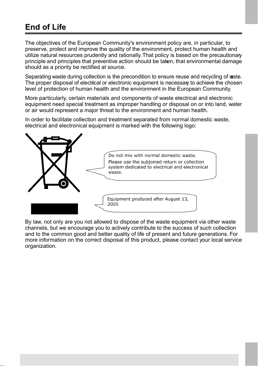
In order to facilitate collection and treatment separated from normal domestic waste,
electrical and electronical equipment is marked with the following logo:
By law, not only are you not allowed to dispose of the waste equipment via other waste
channels, but we encourage you to actively contribute to the success of such collection
and to the common good and better quality of life of present and future generations. For
more information on the correct disposal of this product, please contact your local service
organization.
4
Page 12

Meet your Document System2
Overview
Introduction
2
The system is a folding and inserting system for processing mail easily. The system:
• Feeds documents
• Folds the documents
• Inserts the documents into envelopes
• Seals the envelopes
• Stacks the envelopes
Automatic monitoring ensures the correct number of documents per envelope. The system
can be operated by means of a user friendly interface.The settings of the system (types
of documents, type of envelopes and the type of fold) is recorded in so called jobs. These
jobs can be programmed by an authorized user.
The system is equipped with a variety of special features, such as:
• Document thickness detection
• Programmable jobs
• Automatic jobs
• flexFeed
• Double feed control
• Hopper swap
• Multifeed
• Daily mail
• intelliDeck
• powerFold.
English
5
Page 13

2
English
The figure shows an overview of the system.
Document Feeders (Tower) (1)
This is the feeding part of the system.There are two types of feeders: the automatic
and the special feeder. The automatic feeder does not require any adjustments for the
separation. From a feeder you can feed one or more documents (multi feed). The feeders
have a double feed control (DFC). DFC detects if more documents are fed instead of one.
You can link feeders. This means that two feeders can be linked as pairs. When the first
feeder is empty, the system switches to the other feeder. Meanwhile the empty feeder can
be refilled without stopping the system.
The upper automatic feeder is equipped with a 'daily mail' function.You can use this feeder
to process sets of documents that you cannot process automatically (stapled documents
and sets with varying thickness).
Collating Area (2)
All documents of a document set are collated and aligned in the collating area.
Divert Deck (3)
The Divert Deck automatically throws out incorrect sets of documents. In this way the system
does not need to stop. Correct sets will be transported to the Fold unit.
6
Page 14

Folding unit (4)
The fold unit folds the documents. The following fold types are possible (see Terminology
on page 110):
• No fold
• V-fold
• C-fold
• Z-fold
• Double V-fold
Envelope feeder (5)
Envelopes that are placed on a stack by the user, are fed one by one into the system by
the envelope feeder.
Inserter (6)
After the documents are folded, the documents are transported to the inserter.The inserter
inserts the documents into a waiting envelope. The inserter seals the envelope or not,
depending on the settings. Automatic monitoring ensures the correct number of inserts per
envelope.
Stacker (7)
If you have a High Capacity Vertical Stacker installed on your system, the envelope is
stacked in the stacker, when it leaves the system.The vertical stacker can store up to 325
filled envelopes.
2
English
7
Page 15

2
English
Operating Controls
A - High Capacity Vertical Stacker
B - loc cover
C - unlocking lever for loc
D - power inlet, power switch
E - inserter cover
F - RS232 connector / USB / modem
G - display (operator panel)
H - hand grip vertical transport cover
I - document feed tray
J - collator arm
K - Divert Deck
L - Folding unit
8
M - locking handle Folding unit
N - handle for manual transport of the enve-
lope
O - air plugs for cleaning the sensors
P - handle for manual transport of the mail
set
Q - unlocking handles for rollers envelope
track
R - sealing liquid reservoir
S - bellows for cleaning sensors
T - side cover (opened)
U - thumb wheel for side guide adjustment
V - side guides envelope feed tray
W - lever for envelope separation adjust-
ment
X - envelopes support
Page 16

Control Panel
The control panel consists of the touch screen and the following buttons:
A: On/Off ( ): Switches the system on or off. If the system is not used for one hour,
the system switches to the power save mode. Press the On/Off button to switch back to
the user mode.
B: Stop ( ): The system completes the current mail set and stops, leaving the system
empty and ready for a new set.
C: Start ( ): The system starts to process mail sets.
2
English
The display is covered with a thin pressure-sensitive layer.To avoid
permanent damage of the display, do not use sharp objects to press
on the display.
9
Page 17

2
English
Installing the Document Feed Trays
Place the document feed trays in position:
1. Hold the document feeder slightly inclined as shown in the figure.
2. Place the front end of the document feed tray underneath the two black rollers.
3. Move the document feed tray upwards (lifting the black rollers), until it is possible to
‘hook’ the feeder into place.
4. Move the document feed tray towards the machine and move the hooks over the
mounting points (on both sides).
5. Let the document feed tray rest on the machine.
10
Page 18
High Capacity Vertical Stacker
The High Capacity Vertical Stacker can be used to stack filled envelopes. The vertical
stacker can store up to 325 filled envelopes. The vertical stacker can be equipped with
Mail Piece Production Control (MPPC). In case you have a High Capacity Vertical Stacker,
install it as follows on your system:
1. Move the stacker as indicated by the arrow.
2. Lift the stacker with the suspension hooks over the two rods (upper and lower) and
lower it.
3. Connect the connector
4. Adjust the side guides with wheel A until a margin of 3 to 5 mm is left between the
envelopes and the side guides.
5. For small envelopes it can be necessary to remove the extensions B from the envelope
support.
2
English
Power Up
To start up the system:
You can severely damage the machine if it is connected to the
incorrect power supply. Before plugging in the machine, check if
the local voltage is the same as the voltage mentioned on the type
plate.
1. Connect the system to the mains power supply.
11
Page 19

2. Use the power switch to switch the system on. The power switch is located on the
back of the system.
3.
Press the on/off button next to the display. (Only necessary when the system is
in standby mode.)
2
English
The touch screen shows the home menu.
Home Menu
When you start up the system, the ‘home’ menu appears. With the arrows you can scroll
through the jobs. If you want more information on a job, select the job.
If you just want to start without job definition, press [New job] and select [Automatic] (see
Processing mail sets).
With the home button ( ) you get back to the home menu.The [Menu] button opens
the advanced settings menu (see Opening the Advanced Settings on page 60).
12
Page 20

Job Info
If you want more information on a job, select the job in the ‘home’ menu.
The ‘current job’ menu shows the following information of the selected job:
• Job number and Job name
• Total: total number of envelopes that have been processed using this job
• To do: number of envelopes to do. Only indicated if a ‘stop at’ value is set.
• Stop at: number of processed envelopes at which the system stops.You can set this
number with the [Counters] button.
You can set it between 0 (switched off) and 9999. The system will continue until the
job counter reaches the stop counter value. The system stops and can be restarted.
The stop counter is switched off when it is set to zero.
If you want to reset the daily job counter and the stop counter, press the [Reset TOTAL
Counter] button in the ‘counters’ menu.
2
English
The counter settings are job related.
13
Page 21
2
English
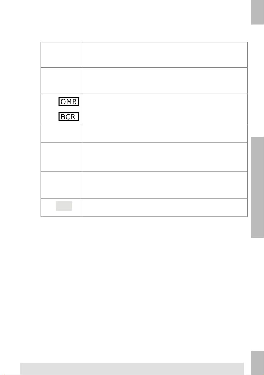
A picture of the system with symbols for the selected features. The following
symbols can be used:
•
Shows the feeders selected to pick documents from (black
is selected). Every selected feeder shows how many sheets
will be fed from the feeder and the length of the sheets.
This sign indicates that the relevant feeders are linked. This
means that when one feeder is empty, the system automatically starts picking documents from the other feeder.
This sign indicates that for the selected feeder OMR or BCR
is switched on (optional).
This sign indicates that the relevant feeder is set for daily
mail.
Gives information about the envelope size (ISO format or
height in mm). An envelope with a cross means that no envelopes are used.
Shows the type of fold, in this case C-fold.
The sign indicates that for the relevant feeder the double
feed detection is switched on.
• [Edit]: use this button to edit the job (see Editing a job on page 42).
• [Info]: if you press the [Info] button, the screen shows how to position the envelope
and documents in the feeders. From this menu you can press a button to view the
reading settings and insert'n Frank / insert'n Mail settings.
14
Page 22

Side Guides
To adjust the side guides it is best to remove the document feed tray from the feeder as
follows:
1. Push handle A downwards.
2. Lift the document feed tray upwards to unhook it and then pull it out from the feeder.
3. Loosen the knob B half a turn.
2
English
4. Grab the side guides in the middle and push them apart as far as possible.
5. Put a small stack of documents between the side guides.
6. Grab the side guides in the middle and push them towards the documents.The space
between the side guides and the documents should be such that the documents have
just enough play to move freely.
7. Re-tighten knob B.
8. Remove the stack of documents.
9. Replace the document feed tray (see Installing document feeders on page 10).
15
Page 23
2
English
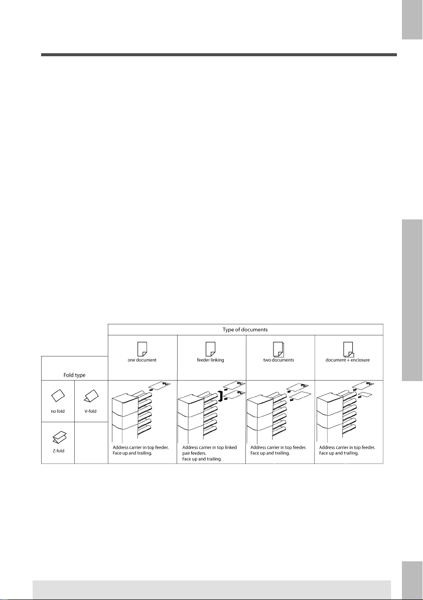
Document Orientation
In case the optional extended powerFold is installed, the following feeding rules apply to
documents with bottom address position:
16
Page 24

Filling the Document Feeder Tray
Fill the document feeder tray as follows:
1. Open the left-hand side guide A by turning it downwards.
The feed rollers will automatically be lifted.
2. Place a stack of documents between the side guides.
3. Turn the left side guide upwards again.
4. Feed the documents (depending on the type of documents and the type of fold) (see
Document Orientation on page 16).
Loading Envelopes
2
English
Before you load the envelopes, make sure the envelope separation and side guides are
correctly set. Proceed as follows:
1. Rotate thumb wheel D to move the side guides C apart.
2. Put a small stack of envelopes between the side guides.
17
Page 25

2
English
3. Move the side guides towards the envelopes. The space between the side guides and
the envelopes should be such that the envelopes have just enough play to move
freely.
If the distance between the side guides is too large, the envelopes
will twist sidewards, when transported into the machine.
4. Pull down small lever A to set the separation.
5. Insert one envelope up to the stoppers. The position of the envelope is flap down and
trailing (bottom side of the envelope pointing to the system).
6. Return lever A.
7. Loosen the stack of envelopes and place the stack on top of the bottom envelope.
8. Shift envelope support B in or out. The top side of the envelope must touch the dotted
line on the support.
9. Turn envelope support B to distribute the weight of the envelopes evenly on both
sides.
18
Page 26

Sealing Envelopes
Switch the envelope sealing on or off:
1. Lift the handgrip to open the top cover.
Shift the blue handle A towards
2.
2
to disable the envelope sealing or towards
to enable the envelop sealing.
3. Close the top cover.
Before you start a job with sealing, wait approximately 5 minutes for the brushes to moisten
or use moistened brushes. For instructions on the installation of brushes, see Clean and
replace brushes on page 91.
English
19
Page 27

2
English
Filling the Sealing Liquid Reservoir
1. Open the front cover A.
2. Fill the reservoir B to the "Max" lip with sealing liquid.
3. Close the front cover A.
Before starting the job, wait approximately 5 minutes for the brushes to moisten or use
moistened brushes. For instructions on the installation of brushes, see Clean and replace
brushes on page 91.
If the liquid reservoir is almost empty the touchscreen shows a message to warn you that
you should refill the reservoir.
Shut Down the System
1.
Press the [On/Off] button to shut down the system.
When the system is busy, it completes and inserts the current set, stops and will be shut
down.
20
Page 28

Options3
Production Feeder
The production feeder is a feeder that can be loaded with a high number of documents. This
feeder is intended to be used for Business Reply Envelopes (BRE), but also 'standard'
documents up to 356 mm (14") length can be processed with it.
Installing the Production Feeder
The production feeder should be installed at the position of feeder no. 1 and/or 4. If you
install it on position 4, you cannot use position 2 and 3 for document feeders.
To install the production feeder as follows:
1. Lift the paper feed rollers with the front edge of the production feeder.
2. Move the production feeder forward until it hooks behind the frame axle.
3. Connect the connector A to the socket B.
3
The production is auto-detected by the system when the system is switched on. This
makes it easy to switch over from the standard document feeder tray to the production
feeder and vice versa.
To make use of a production feeder it is not necessary to (re-)program the jobs.
To allow easier hooking on of the production feeder it is advised
to put the feeding plate in the rear position.
21
Page 29

3
English
Adjusting the Production Feeder Side Guides
Adjust the side guides:
1. Take a stack of documents/BREs and place them in the feeder tray.
BREs with flap down and leading (top side pointing to system).
2. Adjust the side guides by turning the thumb wheel A so the documents/BREs just fit
and can move without resistance.
Too much play causes skewing.
22
Page 30

Adjusting the Production Feeder Document Separation
When the production feeder is used at an automatic separation feeder, the separation is set
automatically.
It can also be used on a feeder position with a manually adjusted separation.
To adjust, proceed as follows:
1. Remove the document feeder trays 2 and 3.
The lowest feeder is feeder 1.
2. Squeeze the two blue handles A and B and shift the feeding plate C as far as possible
to the front.
3. Push knob D forward until it clicks.
4. Place a document/BRE on the feeder tray and slide it in the system till the leading
edge is not visible anymore. Turn knob D counterclockwise if the separation is set to
narrow.
5. Push the document/BRE between the rollers.
6. Turn knob D clockwise to get more resistance and counterclockwise if the separation
is set to narrow.
The separation is adjusted correctly when a slight resistance is felt on the
document/BRE.
7. Pull knob D back when ready.
8. Replace the document feeder trays 2 and 3.
3
English
23
Page 31

3
Feeding documents (Production Feeder)
To feed documents:
When filling the production feeder, make sure that the
document/BREs are positioned parallel in relation to the
feed plate to ensure correct feeding.
The feeding plate assembly will be shifted up automatically (when the system starts
processing) until documents/BREs are underneath the rubber paper pullers.
1. Squeeze the two blue handles A and B.
2. Shift the feeding plate C to the rear position.
3. Loosen the stack of documents and place them in the feeder.
BREs with flap down and leading (top side pointing to system).
High Capacity Document Feeder (HCDF)
The High Capacity Document Feeder is an option that can be delivered from factory, or
added to a 2 or 4 station version by a service engineer.The High Capacity Document
Feeder has a capacity for up to 725 sheets. The normal document feeder tray has a capacity
of 325 sheets.
24
Page 32

Installing the HCDF
To install the feeder tray of the HCDF:
1. Pull down lever A.
2. Hook in the feeder tray.
3. Release lever A.
Adjusting the HCDF Side Guides
To adjust the side guides B:
3
English
1. Loosen the knob D half a turn.
2. Put a small stack of documents between the side guides.
25
Page 33

3. Rotate wheel E.
The space between the side guides and the documents should be such that the
documents have just enough play to move freely.
4. Re-tighten knob D.
Document Separation for the HCDF
3
English
The document separation is set automatically. There are no manual adjustments needed.
Feeding documents (HCDF)
To fill the document feeder tray:
1. Pull down lever A.
The feeder rollers C move up to filling level.
2. Place a stack of documents between the side guides (max. 725 sheets, 80 g/m²).
Feed the documents (depending on the type of documents and the type of fold) (see
Document Orientation on page 16).
3. Release lever A.
26
Page 34

Conveyor Stacker
3
In case you have a conveyor stacker, install it as follows on your system:
1. Position the fork in a forward direction.
2. Move the conveyor as indicated by the arrows.
3. Lift the conveyor with the suspension hooks over the two rods (upper and lower) and
lower it.
Ensure that the fork hooks onto the eccentric.
4. Loosen finger knob A (located below the envelope support) and carefully rotate the
envelope support until it is fitted correctly.
5. Fasten the finger knob.
6. Connect the connector.
Side Exit
The system can be equipped with a side exit and catch tray. The side exit can be fitted
instead of the standard envelope receiving tray. The side exit allows a conveyor or a franking
system to be fitted in line with the system.
The side exit can also be used with a catch tray to achieve vertical stacking. The catch tray
is delivered with the side exit.
English
27
Page 35

3
English
insert'n Frank / insert'n Mail
If this system is connected to a mailing/franking system, insert'n Frank / insert'n Mail allows
you to:
• Switch automatic mailing/franking on or off
• Remotely select a mailing/franking job
• Set the printing/franking value (option)
• Automatically set the printing/franking value using the inserter data
For programming this option, see Mailing and Franking settings on page 57. Refer to the
appendix for an extensive description of the mailing (franking) option.
Mail Piece Production Control
The document system can be equipped with Mail Piece Production Control. This option
enables the system to verify the inserted documents or sets of documents with a database,
which is generated when printing the documents. The system will give a warning when a
mail piece is missing at the exit of the inserter.
Refer to the appendix “Mail Piece Production Control” for an extensive description of this
option.
28
Page 36

Processing Mail Sets4
Introduction
With the system you can process mail sets in the following ways:
• Automatic job: The system automatically picks one sheet from each filled feeder
and processes them into mail sets.
The automatic feature is described in this chapter.
• Manual job: various settings, not available in an Automatic job, can be stored for
re-use in user-programmable jobs (Manual jobs).This includes the use of daily mail.
Working with manual jobs is described in What is a job on page 38.
Automatic job processes mail sets according to the following rules:
• The machine picks one sheet from each filled feeder;
• The picked documents will be folded (if necessary) and inserted into an envelope;
• Only the feeders that feed successfully will be selected;
• Only the Double Feed Control (DFC) of the upper feeder will be selected (this is done
automatically).
The following features are not supported with Automatic job processing:
• Linked feeders (the option where, if one feeder is empty, the system automatically
continues using another feeder);
• Multifeed (picking more than one sheet from a certain feeder);
• Daily mail (see Processing Daily Mail on page 34);
• Reading functionality (see Reading Introduction on page 70);
• No envelope mode (see Envelope settings on page 46);
• Envelopes with open flap (see Envelope settings on page 46).
If you want to use any of these features, you have to use Manual jobs to process the mail
set (see What is a job on page 38).
4
English
29
Page 37

4
English
Processing a Basic Mail Set
A basic mail set consists of documents from one or more document feeders. This set is
inserted into an envelope.
Before you start, make sure you have read the Introduction on processing mail sets on
page 29.
1. From the home menu, press the [New job] button.
2. Choose [Automatic] to start an Automatic job.
3. Load the documents and envelopes into the feeders.
4. Press the [1x] test run button to create one mail set and follow the instructions on
screen.
After a successful test run, it is possible to use the [Save] button
to save the settings of the Automatic job to a new job.
5. Press the [start] button to start the mail set production.
The system stops producing mail sets when one of the feeders is empty or the [stop] button
is pressed.
30
Page 38

Processing a Mail Set with BRE or Inserts
A mail set with BRE consists of documents from one or more document feeders and an
insert/BRE from the BRE feeder. This set is inserted into an envelope.
Before you start, make sure you have read the Introduction on processing mail sets on
page 29.
Load the BREs with the flap down (flap leading).
1. From the home menu, press the [New job] button.
2. Choose [Automatic] to start an Automatic job.
3. Load the documents, BREs or inserts and envelopes into the feeders.
4
English
4. Press the [1X] test run button to create one mail set and follow the instructions on
screen.
5. Press the [start] button to start the mail set production.
The system stops producing mail sets when one of the feeders is empty or the [stop] button
is pressed.
31
Page 39

4
English
Document Separation
The term ‘Document separation’ refers to the adjustment required for separating the upper
document from the rest of the documents in the stack. This prevents pulling too many
documents from the stack at the same time.
The document separation for the automatic feeders is set automatically; there are no manual
adjustments needed.
Feeders 1 and 2 (the feeders in the two lowest positions) can be special feeders. The
document separation for special feeders must be adjusted manually.While special feeder
trays fit in all positions, adjusting the separation is only possible when they are fitted on
position 1 and 2.
Adjust the separation of special feeders as follows:
Adjusting the separation (using a special feeder) is especially
important when you want to process glossy materials.
1. Push the knob A forward until it clicks.
2. Place a document on the feed tray and slide it about 60 mm (2.4 inch) into the system
(turn the knob A counter clockwise if the separation is set too narrow).
3. Push the document between the separation rollers, which are behind the rubber paper
pullers.
4. Turn the knob A clockwise to get more resistance or counter clockwise to lower the
resistance.
The separation is adjusted correctly when a slight resistance is felt on the document.
5. Pull the knob A back again when ready.
32
Page 40

Adjustment of the Document Stoppers
The document stoppers mark the position at which the documents coming from the feeder
turn towards the folding area. The position of the document stoppers is automatically
determined by the system during the job programming.
Initially the document stoppers are adjusted for position B. In this position a wide variety
of documents can be handled (max. 297 mm; 11.7 inch) and adjustment is not needed.
When a job is selected in which a different stopper position has been programmed, the
operator has to put the document stoppers in the correct position as indicated by the display.
To adjust the stopper position:
1. Lift and hold the collator arm D.
2. Squeeze the stopper and pull the front side tab up.
3. Place the flat back tab into the correct slotted hole.
4. Push the stopper into position.
4
English
Stop position A can handle documents up to 148 mm (5.8 inch), stop position B can handle
documents up to 297 mm (11.7 inch) and stop position C can handle documents up to 356
mm (14 inch).
33
Page 41

4
English
Processing Daily Mail
The daily mail function is only available when reading is not
activated. When daily mail is set, the links to the daily mail feeder
will be deselected automatically.
When the daily mail function is selected DFC is not available.
To process documents or sets of documents, which can not be processed automatically
(e.g. stapled documents), the top feeder is equipped with a daily mail switch.
To use the Daily Mail function:
Select a job where the daily mail function is selected. You can recognize the daily
1.
mail by the icon in the job information menus.
2. Turn down the left side guide A of the upper tray. Now you can see the Daily Mail
handle B.
3. Move the handle to the right to enable the Daily Mail function.
4. Turn side guide A upwards.
5. Press the [start] button to start the job.
6. Place the document or document set in the feeder (see Filling the Document Feeder
Tray on page 17).
The document or document set will be folded and inserted into the envelope as
described in the selected job.
7. Place the next document or document set in the feeder. The system will keep running
to process the inserted document or document set.
34
Page 42

8. When finished with Daily Mail, press the [stop] button to stop the job.
9. Set the Daily Mail handle B to the ‘AUTO’ position to disable the Daily Mail and enable
the automatic document separation.
Test Run
Before starting an Automatic job, it is possible to perform a single test run.
This test run is intended to validate the settings of the Inserting System:
• Inspect and adjust the stop position of the envelope.
• Check the fold settings for one set.
• Check if the address is correctly positioned behind the envelope window.
Adjusting the Address Position
If the address on your mail is not correctly positioned behind the envelope window, change
the address position as follows:
Adjusting the address position is only possible after running a test
run (by using the [1x] button).
1. Choose a job and press the [1x] button.
4
English
2. Press No if asked if the mail set is correct.
3. Press Yes if asked if the documents are inserted correctly.
4. Press No if asked if the address is readable.
5. Follow the steps in the wizard.
35
Page 43

4
English
Adjusting the Envelope Insert Fingers
To make a good insert of the document set into the envelope, the insert fingers A should
be about 5 mm (0.2 inch) inside the envelope.
The outer fingers should be about 5 to 10 mm (0.2 to 0.4 inch) from the edges of the
envelope.
To verify that the position of the fingers is correct:
1. Choose a job and press the [1x] button.
2. Follow the steps in the wizard.
To adjust the envelope insert fingers:
1. Loosen the knurled knob D on top of each finger.
2. Adjust each finger so that the tip enters about 5 mm (0.2 inch) into the envelope.
3. Re-tighten the knurled knob.The fingers can be moved sideways to the desired position.
4. Place the outer fingers about 5 to 10 mm (0.2 to 0.4 inch) from the edges of the
envelope.
36
When adjusting the fingers sideways, make sure that finger A is
not positioned over sensor B.
Check the position of the insert fingers when changing to a different
type of envelope.
Page 44

Verifying the Insert Position
To make a good insert of the document set into the envelope, the envelope should be
positioned correctly.
The document set is inserted correctly if the flap folding line of the envelope is positioned
underneath the green roller C.
To verify the insert position:
This adjustment must only be checked in case of problems or when
changing the envelope type.
1. Choose a job and press the [1x] button.
2. Lift the locking lever of the loc and pull the loc into the vertical position.
3. Press No until the question about envelope position appears.
4
English
4. Press No again and follow the instructions on screen.
37
Page 45

5
English
Working with Jobs5
What is a job
If you have to process a lot of mail sets of the same type (for example bills), you can save
the settings to a 'job'. The next time you just select the job and immediately start without
defining any settings.
The following settings are saved in a job:
• Envelope type/size;
• Which document feeders should be used, how many documents should be fed from
each feeder and document height for each feeder;
• Feeder linking on/off;
• If BREs or insert cards should be included;
• Address position;
• Fold settings;
• Double feed control settings;
• Reading settings (option);
• Mailing and Franking settings (option);
• Mail Piece Production Control settings (option);
• Batch Counter, defining the number of mail sets that the job must process. The job
will automatically stop processing when this number is reached.
Creating a new job
To create a new job:
1. From the home menu, press the [New job] button.
38
Page 46

2. Press [Manual] to create a new job.
For [Automatic], see Processing a basic mail set on page 30.
3. Enter the pin code 2546.
4. Press [OK] to confirm the selected free job number.
A new selected job number starts with default settings.
The job settings menu opens. The meaning of all buttons and settings is explained in
Job settings on page 46.
5
English
39
Page 47

5
English
5. Press [Save] to save the job with the entered settings under the specified job number
and name.
To name a job, see Job name settings on page 56.
6. Press the [1x] button to verify that the insert position and address position are correct
(see Verifying the Insert Position on page 37 and Adjusting the address position on
page 35).
Performing a test run
Before starting a job, it is possible to perform a single test run with the settings of the current
job.
To perform a test run:
1. In the home menu, use the arrows to scroll through the Job selection list.
2. Select the job you want to use.
3. Click the [1x] button.
40
Page 48

4.
Press the button if you want to adjust the envelope position before running
the test run (see Adjusting the Envelope Position on page 41).
5. Press the [1x] button to perform the test run.
Adjusting the Envelope Position
Before performing a test run, it is possible to adjust the envelope position.
To adjust the envelope position:
1.
Press the button to start adjusting the envelope position.
2. Use the arrows beneath the ruler to adjust the envelope position.
3.
Press the to check the new alignment.
5
English
4. Press the [OK] button to accept the new alignment.
41
Page 49

5
English
Using a job
If you want to use an existing job:
1. From the home menu, select the job you want to use.
2. If you want to perform a test run:
Press the [1x] button to do a test run.
3. If you want to change the counter for this job:
Press the [Counters] button to make changes to the amount of mail sets that the job
produces.
4. Press the [Start] button to start the job.
Editing a job
To edit an existing job:
1. From the home menu, select a job you want to edit.
2. Press the [Edit] button.
42
Page 50

3. Enter the pin code 2546.
The job settings menu opens. See Job settings on page 46 for the meaning of all
buttons and settings.
4. Press [Save] to save the job with the entered settings under the specified job number
and name.
5. Press the [1x] button to verify that the insert position and address position are correct
(see Verifying the Insert Position on page 37 and Adjusting the address position on
page 35).
Copying a job
To copy existing job settings to a new job:
1. Press the [Supervisor] menu button from the main menu.
2. Enter the pin code 2546.
5
English
43
Page 51

3. Press the [Job] menu button.
The job menu opens.
5
English
4. Press the [Copy job] button.
The copy job menu appears.
5. Press the arrows if you want to select another job number to copy from or to copy to.
You can only copy job settings to new jobs.
6.
Press the button for details of the job to copy from.
7. Press [OK] to copy the job settings.
If all jobs are programmed the touch screen shows “No more free jobs”.
It is possible to copy an Automatic job into a job. Before an Automatic job can be
copied, it has to be defined successfully (see Processing a basic mail set).
44
Page 52

Deleting a job
To delete an existing job:
1. Press the [Supervisor menu] button from the main menu.
2. Enter the pin code 2546.
3. Press the [Job menu] button.
The job menu opens.
5
English
4. Press the [Delete job] button.
The delete job menu appears.
When you press [OK], the job is deleted without a warning.
45
Page 53

5. Select a job number and press [OK].
Job settings
From the job settings menu the following settings are available:
•
Envelope settings (see Envelope settings on page 46);
•
Document settings (see Document settings on page 48);
•
Fold settings (see Fold settings on page 50);
5
English
•
Reading settings (if installed, see Reading settings on page 52);
•
Double feed control settings (see Double feed control settings on page 55);
•
Job name settings (see Job name settings on page 56);
•
Mailing/Franking settings (if installed) (see Mailing and Franking settings on
page 57);
•
Mail Piece Production Control (MPPC) settings (if installed) See the appendix
operator manual Mail Piece Production Control.
If you want to view the job details of the current job, press the button. If you want to
run a test, press the [1x] button.
Envelope settings
In the ‘envelope settings’ menu you can define the envelope properties and switch the
sealing on and off.
46
Page 54

In the top of the screen, three selection buttons are displayed, from which one can be
selected. The selected settings button will be highlighted.
•
Press the button to select an envelope with closed flap. This means that the
envelopes are fed with closed flap.
Use the button to enter the applicable dimensions. It is also possible to select
ISO standard envelopes or dimensions in inches (depends on the installation settings).
The envelope height can be set between 90 mm (3.5 inch) and 162 mm (6.38 inch).
•
Press the button to select an envelope with open flap. This means that envelopes
are fed with open flap. Use the upper button to enter the applicable dimensions.
The envelope height can be set between 90 mm (3.5 inch) and 162 mm (6.38 inch).
It is also possible to select ISO standard envelopes or dimensions in inches (depends
5
on the installation settings). Use the second button to enter the flap height.The
flap height can be set between 32 mm and the envelope height minus 32 mm (1.26
inch).
•
Press the button to define a job without inserting the documents in envelopes
(no envelope mode). This can be useful for jobs, where documents only have to be
sorted and/or folded.
English
47
Page 55

5
Document settings
In the ‘document settings’ menu you define the document formats and the number of
documents that must be picked from the different feeders.
English
•
Press the button to set the number of sheets for the different feeders.
•
Press the button to select a feeder. The selected feeder is highlighted.
• You can feed more than one document for your document set from each feeder. This
is called Multi Feed.
Press the arrows to change the number of sheets that must be picked from the
highlighted feeder. When the number of documents is 0, the selected feeder will be
deselected.
When a feeder is set to daily mail the number of documents is
always 1 and can not be set in this menu.
The maximum number of sheets in a set is 25. When folding is
used the maximum set thickness is 8 sheets in letter fold and 10
sheets (80 gr./m2) in single fold.
48
Page 56

•
Press the button to enter the document height. The height or the ISO format of
the document will be displayed next to the relevant feeder.
•
Press the button to select a feeder. The selected feeder is highlighted.
•
Press the button to show a numeric keypad to enter the exact dimension of the
document.
Dimensions can be entered in mm, inches or as standard ISO paper dimensions
(depending on installation settings). The system will not allow entering dimensions
out of technical ranges. The document size can be set between 90 mm (3.54 inch)
and 356 mm (14 inch).
The default document size setting of a new job is 297 mm (11.7 inch).
•
Press the button to link two feeders. This function enables to fill two adjacent
feeders with the same documents. When the first feeder is empty, the system
automatically swaps to the other feeder.
5
English
•
Press the button to select two adjacent feeders. The selected feeders will be
highlighted.
•
Press the button to link two highlighted feeders.The link-symbol will be displayed
between the selected feeders.
When linking two feeders, the program will automatically apply the
number and format of the documents of the lowest feeder to the
other feeder.
49
Page 57

5
When a feeder is selected for reading, the feeder below can not be
linked to this reading feeder. The reading feeder can be linked to
a feeder above when it is not selected for selective feeding.
•
Press the button to enter the setting of the daily mail function.
This function enables to process documents or sets of documents, which can not be
processed automatically (see Processing Daily Mail on page 34). The upper feeder
is automatically selected.
•
Press the button to enable the daily mail function.The icon appears behind
the upper feeder. If you press the button again the daily mail function will be
disabled.
English
The daily mail function is only available when reading is not
activated. When daily mail is set, the links to the daily mail feeder
will be deselected automatically.
When the daily mail function is selected DFC is not available.
Fold settings
In the fold settings menu you can adjust the folding dimensions and folding type.
Select the Address type. In case the system is equipped with the optional bottom address
application you can switch between Top and Bottom address position.
50
Page 58

Select the fold type. The following choices are available for top address:
•
No fold (no settings required)
•
V-fold
•
C-fold
•
Double V-fold
•
Z-fold
For Bottom address only three fold types are possible.
Except when no fold is required, the touch screen shows a simple diagram of the document
with the fold positions.
To change the fold positions press the button next to a fold. Enter the required position
of the relevant fold.
5
English
51
Page 59

5
English
The touch screen will indicate when entered positions are out of
range.
Reading settings (option)
For a full function description of reading, see Reading Introduction on page 70. In the
‘reading settings’ menu it is possible to enable or disable the Optical Mark Recognition
(OMR) or Barcode Reading (BCR) function and to adjust the basic settings. The first ‘reading
settings’ menu covers the following settings:
52
Page 60

Code type: default is the setting ‘none’: reading is disabled.
•
Change the setting with the button. The following codes are possible:
- 1-track OMR
- BCR for reading barcodes
- Flex 1-9 for reading customer specific codes (only if flex dongle is installed)
•
Reverse reading: press the button to set reverse reading on or off (see Reverse
reading on page 71).
•
Read from feeder: press the button to select a feeder to activate reading on.
By pressing the [Next] button the next reading settings menu appears.
In this menu you can define the location and the width of the OMR code. The position from
top should be between 15 mm (0.6 inch) and the document length minus 20 mm (0.8 inch).
If you press [Next], you can load an OMR sheet to verify the OMR settings. The system
processes the OMR sheet and shows the read marks. The information button shows the
interpretation of the marks.
If you selected BCR, you can update your barcode definition with a configuration sheet or
load a sample BCR sheet to learn the BCR location.The system processes the BCR sheet
and shows the read code. The information button shows the interpretation of the code.
By pressing the [Next] button the next reading settings menu appears.
5
English
53
Page 61

5
English
• Stop on misread: define if the system should stop or not when a code is misread. In
case of “yes”, the system stops after a misread. The incorrect set is diverted. After
resetting the system, the final part of the set is also diverted and the system starts
processing again. The diverted set should be checked by the operator.
When “stop on misread” is set to “no”, the system does not stop after a misread.
The incorrect set is diverted. The final part of the set is also diverted and then the
system starts processing again. After 5 misreads in a row, the system stops and
an error code is generated.
• Stop on sheet overflow: define if the system should stop or not when a set exceeds
the maximum number of sheets, as defined at the "Max. sheets setting". In case of
“yes”, the system stops when the number is exceeded.The incorrect set is diverted.
After resetting the system, the final part of the set is also diverted and the system
starts processing again. The diverted set should be checked by the operator.
When “stop on sheet overflow” is set to “no”, the system does not stop when a set
exceeds the maximum number of sheets.The incorrect set is diverted. The final part
of the set is also diverted and then the system starts processing again.
• Max. sheets: use the arrow buttons to select the maximum amount of sheets in the
set of documents.
The maximum number of sheets in a set is 25. When the number
of sheets exceeds 8 or 10, depending on the fold, the document
can not be folded anymore. In this case, the maximum length of
sheets is 148 mm for a C5/6 envelope. Also make sure that the
fold is set to No fold. Ignoring this will certainly lead to stoppages.
When the maximum number of sheets exceeds the programmed
maximum number of sheets in a set, the system stops and
error VS:110 will be displayed. After removing the set and pressing
the [Reset] button, the system will start and repeat the process
until an insert or divert mark is encountered, error VS:135 (final set
part) will be displayed.
54
Page 62

Double feed control settings
In the ‘DFC settings’ menu you can set Double Feed Control (DFC) for the different feeders
on or off.
5
•
Press the button to select a feeder.
•
Press the button to switch the DFC on or off.
When switched on, the icon is displayed. When a job is started, the first document
taken per feeder is used for a reference measurement.
When a document is exceeding that reference thickness an error will be displayed.
•
Press the button to set Continue on double on or off. If Continue on double is on
(“yes”), the machine will not stop if two sheets are feeded instead of one. The
document-set containing the double sheets will be diverted.
When Daily mail is selected, the DFC of the upper (Daily mail)
feeder is switched off automatically.
English
55
Page 63

5
English
Job name
It is possible to store the job with a meaningful job name, to easily recognize the job. This
name is displayed at job selection. Enter a job name with the alpha-numeric keypad.
•
Use the button to clear a character left of the cursor position (backspace).
• Use the [CE] button to clear all entered characters and start again.
56
Page 64

Mailing/Franking settings (option)
If this machine is connected to a mailing/franking machine, this option allows you to select
the franking mode.
Use the button to choose between:
• Pass through: franking off
• Franking: the mailing (franking) system will print/frank the envelopes according to
the local mailing (franking) system settings. When you press the [Ok] button, you
can choose a franking job from the franking machine.
• Inserter: the mailing (franking) system will print/frank the envelopes according to the
size data communicated by the inserter. When you press the [Ok] button, you can
enter the weight of single documents and envelopes and the envelope width.
To link a mailing (franking) job to the inserter job, use the arrow buttons to select a
job. If no link is required, select ‘Current job’.
5
English
Refer to the appendix for an extensive description of the mailing (franking) option.
57
Page 65

5
English
Mail Piece Production Control settings (option)
For Mail Piece Production Control settings, see the appendix operator manual Mail Piece
Production Control.
58
Page 66

Advanced Settings6
What are Advanced Settings?
Advanced Settings are all settings that can be found under the Display Settings Menu and
the Supervisor Menu.
The Display Settings menu contains the following settings:
6
English
• Set screen brightness (see Changing the Display Settings on page 60);
• Set interface volume (see Changing the Display Settings on page 60);
• Change screen orientation (see Changing the Display Settings on page 60).
The Supervisor Menu contains the following settings:
59
Page 67

6
English
• System info (see Viewing System info and Software versions);
• Options (see Activating an option on page 62);
• Test (see Test menu on page 63);
• Online Services (see Start-up Online Services on page 82);
• Job menu (see What is a job on page 38);
• Read config sheet (see Reading a configuration sheet on page 74);
• Job settings (see Job Settings on page 65).
Opening the Advanced Settings
If you want to see or edit any of the Anvanced Settings:
1. From the home menu, press the [Menu] button.
2. Choose if you want to see the Display Settings or the Supervisor Menu. Press the
according button to enter that menu. Please note: to access the Supervisor Menu,
enter the PIN-code 2546. After entering the correct pin code the Supervisor Menu
appears.
Changing the Display Settings
From the Display Settings screen, you can change various settings.
To change the Display Settings:
1. Use the arrows next to the brightness symbol to increase or decrease the display
brightness.
60
Page 68

2. Use the arrows next to the volume symbol to increase or decrease the interface
volume.
3.
Press the button to toggle the orientation of the display screen. This function is
useful in case of applications when the operator is working on the backside of the
system.
Viewing System info and Software versions
From the Supervisor menu, you can view the System info and Software versions.
Proceed as follows:
1. From the Supervisor menu, press the [System info] button.
The System info menu opens.
Here, the following information is shown:
- Flex certificate - this option is used for OMR;
- Counter since last visit - the counter value since the last service visit;
- Last error - The last error generated by the system.
6
English
2. Press the [Software versions] button to view information on the version of the installed
software.
The ‘software versions’ menu opens.
This screen shows the software versions that are present in the total system.
Pressing the [i] button shows the subversion revision numbers instead of the standard
software version numbers. Generally these are used for development reasons, but
sometimes it’s convenient to have them for trouble shooting reasons.
61
Page 69

What are licensed options?
The Option menu shows the following information:
6
English
• Chip ID
• System ID
• Installed options.
These software options are enabled using license codes. These license codes,
together with the identification number of the machine enable the relevant options.
The enabled and available software options are displayed in this screen. Contact
your dealer for information about these license codes.
The system supports the following licensed options:
- Advanced reading (see Reading Introduction on page 70);
- OMR 1 track (see OMR Code Description on page 77);
- BCR 1D (see BCR Code Description on page 73);
- Flex reading (see Reading Introduction on page 70);
- insert'n Frank / insert'n Mail (INF) (see Mailing and Franking settings on page
57);
- MPPC (see the operator manual 'Mail Piece Production Control');
- OLS (see Online Services introduction on page 82).
Activating an option
To add a licensed option:
1. In the Options screen, press the [Add] button.
62
Page 70

2. Use the keypad to enter the license key code that you received from the supplier to
activate the relevant option on this machine.
If needed, use the arrow keys to navigate through the entered characters.
3. Press the [OK] button to add the licensed option.
The system will now verify the license key.
4. Switch the system off and on.
Test Menu
The Test menu can be used to check the system, reset all photocells and execute reading
tests.
The menu consists of the following functions:
• Diagnostics - Use this function to check if all motors, clutches and sensors are
correctly connected. This test derives the status of the actuators and clutches by
briefly activating the actuators and then measuring the current (see Running
diagnostics on page 64);
• Reset photocells - Use this function to calibrate all photocells (see Resetting photocells
on page 93);
• OMR test - Use this function to test the OMR functionality (see Running an OMR test
on page 80);
• BCR test - Use this function to test the BCR functionality (see Running a BCR test
on page 76).
6
English
63
Page 71

6
English
Running diagnostics
To run a diagnostics of the system:
1. In the Test menu, press the [Diagnostics] button. The Hardware test screen appears.
2. Remove all documents and envelopes and close all covers before starting the diagnose.
3. In the Hardware test menu, press the [Start diagnose] button.
When the test is finished, the Status report is shown, showing a list of all problems
found during diagnostics.
4. If no problems were found, press the [OK] button.
If problems have been found that can not be solved, call your service organization.
64
Page 72

Job Settings (Supervisor)
Job settings normally will be changed by a service engineer only.
Therefore first consult the supplier’s Helpdesk before changing any
settings. Changes to the job settings can result in malfunctioning
of jobs.
The "job settings" menu (supervisor) can be opened from the "supervisor menu". From this
menu system parameters can be set.
The "job settings" menu shows the following functions:
• Flap Closer - Use this option to improve the envelope sealing process by changing
the flap closer offset for one or more defined jobs (see Changing the Flap Closer
Offset on page 66);
• Envelope clearing - Use this option to define when envelopes are cleared from the
system (see Changing the Envelope Clearing on page 66);
• System output - Use this option to change the output mode for one or more defined
jobs (see Changing the System Output on page 67);
• Document offset - Use this option to change the document offset for one or more
defined jobs (see Changing the Document Offset on page 68);
• BRE offset - Use this option to change the BRE offset for one or more defined jobs
(see Changing the BRE Offset on page 68).
6
English
65
Page 73

6
English
Flap Closer Offset
To change the flap closer offset for a selected job:
1. Use the arrows next to "Select job" to select for which job (Job 1-25 or Auto) you want
to make the changes.
2. Use the arrows next to "Flap Closer offset" to change the Flap closer offset for the
selected job.
The offset can be varied between -20 and 20. If for example the offset is set to +10
the sealing process will be activated 10 pulses later than initially.
3. Press the [Save] button to save the changes to the selected job.
Envelope Clearing
To define when envelopes are cleared:
1.
Use the next to "Job selection" to set wether the envelopes should be cleared
(always, never or only after asking) when the operator selects a job.
2.
Use the next to "Edit job" to set wether the envelopes should be cleared (always,
never or only after asking) after the operator has edited a job.
3. Press the [OK] button to accept the changes.
66
Page 74

System Output
To change the output mode for a selected job:
1. Use the arrows next to "Select job" to select for which job (Job 1-25 or Auto) you want
to make the changes.
6
2.
Use the next to Output to change the Output mode for the selected job.
Mode 1 focuses on the versatility of paper parameters (paper thickness; document
length), i.e. correct operation under even extreme paper conditions.
Mode 2 is the default mode, and focuses on high speed and is achieved as follows:
- During multi feed (more than one page from one feeder) the movement on the
collator is minimal. In mode 1 the divert unit will be used for completing the
collating process.
- During the transportation of a set from the collator into the powerFold, the next
set is going into the collator already. This results in temporary overlapping sets
with two different transport directions. In mode 1 the set has left the collator
completely before the next set enters the collator.
- Anticipation call for the envelope is used. That means that a (folded) set is
leaving the powerFold already before the envelope is ready on the insert position.
In mode 1 the envelope is on the insert position already before the set leaves
the powerFold.
It is advised to use Mode 1 with a paper thickness of 65 g/m2 or less, a document
length of 12 inch (305 mm) or higher, and for situations where Mode 2 is not functioning
properly. In all other cases Mode 2 is advised.
3.
Use the next to BRE with window to select if the reply envelope has a window or
not.
This option is only available for Output mode 2.
English
4. Press the [Save] button to save the changes to the selected job.
67
Page 75

6
English
Changing Document Offset
To change the document offset for a selected job:
1. Use the arrows next to "Select job" to select for which job (Job 1-25 or Auto) you want
to make the changes.
2. Use the arrows next to "Document offset" to change the Document offset for the
selected job.
The vertical transport of documents fed by the various feeders is arranged in such a
way that the documents are partially overlapping each other.This overlapping scheme
ensures that the documents are properly aligned in the collator area.
In the “document offset” menu you can set the extend to which the documents are
not overlapping each other, i.e. the document offset value.The default value is 50
mm (2.0 inch). The document offset can be varied between 20 mm (0.8 inch) and 250
mm (9.8 inch).
3. Press the [Save] button to save the changes to the selected job.
Changing BRE Offset
To change the BRE offset for a selected job:
1. Use the arrows next to "Select job" to select for which job (Job 1-25 or Auto) you want
to make the changes.
68
Page 76

2.
Use the button next to BRE with window to set the BRE offset to On of Off.
If a document is longer than the set address fold but shorter than the envelope height,
this document sometimes will be unnecessarily folded. Under certain conditions this
document can be prevented from being folded. This can be implemented with the
menu “BRE offset” (BRE means Business Reply Envelope).
For each of the jobs 1 through 25 and Automatic an offset can be switched on or off
using the button.
In the case of offset “on” the last document that was added to the set will be shifted
from the rest of the set (offsetting). This document will be held back during a certain
distance. This means that the trailing edge of this upper document leaves the collator
at last. This document will not be folded. During the insertion into the envelope the
documents of the set will be realigned.
The conditions are:
- The feeder that supplies this upper document (BRE) is set to one document per
set (no multi feeding).
- The document directly beneath this document must be at least 60 mm (2.4 inch)
longer than the BRE.
- The upper document must be longer than the set address fold.
- The folding mode is either V-fold or C-fold (no Z-fold).
- The upper document must be shorter than the envelope height.
The whole BRE offset is based on friction between documents within a set.Therefore
it is necessary to make use of these conditions to reduce the risk of bad transporting,
folding and inserting.
It is possible to use the BRE offset for a BRE and an enclosure
(card) in one set. The extra condition is that this enclosure is equal
to or smaller than the set address fold and should be placed direct
underneath the BRE in the set.
6
English
3. Press the [Save] button to save the changes to the selected job.
69
Page 77

7
English
Reading7
Introduction
The folding and inserting system can be equipped with reading. This allows the system to
read special codes that have been printed on the documents. These codes contain
information about the processing of the sheets. Three types of codes are available:
• 1-track OMR: Optical Mark Recognition
• BCR: BarCode Reading
• Flex 1-9
Depending on the settings, the code tells the system if:
• The document set is complete
• Enclosures must be added to the set
• The system must stop
• The set is complete (no pages are missing)
The sheets with the printed code are placed in a feeder. Depending on the programmed
code, the other feeders can be used as selective feeders to add enclosures.
In case of a Z-fold, the address has to be printed on the last page of the set (see Document
orientation on page 72 for the code position). With the other fold types, the first sheet of a
set always contains the address. A full length code is printed on every sheet of a set. The
code must appear at the same location on every page regardless of the actual code length.
The code on the last sheet of the set contains the insert instruction (unless reverse reading
is used, see Reverse reading on page 71).The other sheets carry the accumulate
instruction. If a parity check is used with OMR, this is checked on each sheet. If the “page
n of m” code is used with BCR, the set will be inserted when n equals m.
70
Page 78

General requirements for printing codes
If you print documents for reading:
• Make sure the ribbon or toner quality is sufficient.
• Print the code in black.
• Codes on the same sheet must have equal intensity.
• Print the code at the same position on every sheet.
• Be aware of "background noise".The reading function can be disturbed by: color
changes on the form, background design and a logo or copy on the opposite side of
the sheet that will bleed through.
• For matrix printers near letter quality (NLQ) printed characters are preferred to obtain
maximum blackness (double strike).
For more information on how to print a reading code on your
document, contact your service organization.
7
Reverse reading
Reverse reading means that the insert mark (OMR) is on the first page of the set. The
system will detect the end of a set by detecting the first page of the next set. In case of
BCR use the Customer ID to complete a set. If the ID changes, the set is inserted.
When reverse reading is used, the reverse reading symbol is shown in the "Job info" screen.
In case the feeder runs empty, the last set is still on the collator because the beginning of
the next set could not be detected. In this case the feeder empty message contains
an [Ignore] function. By pressing the [Ignore] button the set on the collator will be inserted.
Because of the feeding and collating principle, reverse reading has the following limitations:
• The last mark of the code should be printed maximally 85 mm (3.3 inch) from the
top.
• Enclosures and selective enclosures cannot be handled.
English
71
Page 79

7
English
Document Orientation
Switch on the reading function and set the position of the reading marks as described in
BCR Code Description on page 73 and OMR Code Description on page 77.
Document orientation:
72
Page 80

BCR Code Description
Position of the code on the document.
7
English
Minimum line thickness of a bar: 0.25 mm (0.01 inch)
The thickness ratio of thick bars versus thin bars: 2.2
The white area in the picture shows the limits where the code can be printed.
BCR license types
There are two BCR license types:
• Basic
• Advanced
73
Page 81

7
English
BCR basic license
For the BCR basic license the following functions are available:
• Page N of M: as long as N is below M, the document set is not complete. As soon
as N=M, the set is complete and will be inserted into an envelope.
• Insert/Accumulate: defines when a document set is complete and must be inserted
into an envelope.
• Customer ID: BCR uses the Customer ID code to complete a set.This is only possible
with reverse reading. If the ID changes, the set is inserted.
At least codes for accumulate and insert are required.
BCR advanced license
For the BCR advanced license the following functions are available:
• The basic functions (page N of M, insert/accumulate, Customer ID)
• Sheet sequence - every sheet has a number, regardless of the document set it is
part of. If a sheet is missing, an error is generated.
• Group sequence - every document in a set has the same group number. If one
document set is missing, an error is generated.
• Selective feed - if the system reads the command, an enclosure from the enclosure
feeder is added to the set. This function is printed on the last sheet of a set.
• Divert (Divert & Continue) - The set will be diverted and the system continues.
• Stop (Divert & Stop) - The set will be diverted and the system stops indicating error
(VS:113 - Reading stop - Stop mark read).
Reading a configuration sheet (BCR only)
If you want to set the code definition for BCR, you can use a BCR configuration sheet.
To read a configuration sheet:
1. In the Supervisor menu, press the [Read config sheet] button.The Barcode
configuration sheet menu appears.
2. Load the barcode configuration sheet in the top feeder.
74
Page 82

3. Press the [Run sheet] button.The BCR settings screen appears.
4. In the BCR settings screen, confirm that all settings are read correctly.
Note that this screen consists of two parts. Use the arrows at the bottom of the screen
to navigate between the two parts of this screen.
5. Press the [Back] button to leave the BCR settings menu.
6. Press the [Save] button to save the BCR settings that were read from the configuration
sheet.
7
English
Saving these settings will change the barcode definition for ALL
jobs where reading is used.
75
Page 83

7
English
Running a BCR test
To run a BCR test:
Before running a BCR test, select a job that uses BCR reading.
1. In the Test menu, press the [BCR test] button. The BCR test menu appears.
2. Press the [Test] button to start the BCR test. After the test is finished, the Result
screen appears.
3. In the Results screen, evaluate the test results.
Use the button to see the BCR info, or use the button to cycle through all
BCR codes that were detected during the test. Select the one you want to use for
reading.
4. Press the [Back] button to return to the BCR test menu.
76
Page 84

OMR Code Description
Position of the code on the document:
7
English
Minimum line thickness of a mark: 0.2 mm (0.008 inch)
Default the first mark from the top is set to: 100 mm (3.9 inch).This parameter is set in the
job settings.
The code must have a consistent number of marks on every page.
The white area in the picture shows the limits where the code can be printed.
OMR license types
There are two OMR license types:
• Basic
• Advanced
77
Page 85

7
English
OMR basic license
For the OMR basic license the following functions are available:
• Start mark: indicates the start of the code.
• Insert/Accumulate: defines when a document set is complete and must be inserted
into an envelope.
• Parity check: by adding a parity mark the reading code can be checked. The sum of
the marks must be even.
• Safety Mark: is used as an extra security.With skewed paper the reading head can
miss part of the reading code. In these situations the safety mark is not read, and
the system will give an error. The safety mark also indicates the end of the reading
code. This mark must always be present on the document if it is part of the code
definition.
The minimum code is one mark in one line (insert). However for reliability it is advised to
use at least 2 marks. The first line is the start mark. A mark printed on the second line
means insert. No mark on the second line means accumulate.
78
In some cases, on request of the customer, the reading of the basic
commands can be reversed by the service organization.This means
that no mark is interpreted as an insert command and that for the
accumulate command a mark has to be printed.
Page 86

OMR advanced license
For the OMR advanced license the following functions are available:
• The basic functions (Start, Insert, Parity, Safety)
• Divert (Divert & Continue) - The set will be diverted and the system continues.
• Stop (Divert & Stop) - The set will be diverted and the system stops indicating error
(VS:113 - Reading stop - Stop mark read).
• Selective Feed - The machine will selectively feed an enclosure when commanded
so.
• Sequence Check - Sheets in a stack can accidentally get out of sequence or can be
missing. This can be detected by the sequence check. Each sheet has a binary code
that is a part of the reading code. Depending on the application one, two or three
marks are used by sequence check.
OMR general remarks
General remarks:
• In case of OMR the marks must always be used in the sequence as shown in the
figure.
• If a function is suppressed the following function will move upwards one line.
• The mark definition is a service setting.
7
English
79
Page 87

7
English
An Example of OMR Code
In the figure the legend for the following example is shown. In this example, a set of 8
sheets with one selective feed and three sequence check marks is shown.
• The first position is used for the start mark which must be printed on every sheet.
• The second mark position is used for the insert/accumulate command. A printed
mark means insert, no mark means accumulate. Therefore the mark is printed on
the last sheet of the set.
• Position 3 is reserved for selective feed from the enclosure feeder. Print a mark on
position 3 when a selective feed from the enclosure feeder is required. The marks
are printed on the last sheet of the set.
• Position 4, 5 and 6 are used for the sequence check marks. In this case a three mark
sequence check is used.
Running an OMR test
To run an OMR test:
Before running an OMR test, select a job that uses OMR reading.
1. In the Test menu, press the [OMR test] button. The OMR test menu appears.
80
Page 88

2. Press the [Test] button to start the OMR test. After the test is finished, the Result
screen appears.
3. In the Results screen, evaluate the test results.
Use the button to see the OMR info.
4. Press the [Back] button to return to the OMR test menu.
7
English
81
Page 89

8
English
Online Services8
Online Services
The folding and inserting system can be equipped with Online Services.This option enables
the system to connect to a central server. During the connection data is downloaded to
and uploaded from the system.The system always initiates the connection, it is not possible
to make a connection from outside to the system.
Ask your supplier if this option is available.
Start-up Online Services
To start-up Online Services:
1. From the supervisor menu choose [Online services].
The ‘Online Services’ menu shows the following functions:
- Connection: opens the ‘connection’ menu to create a connection to a central
server and to view the connection history (see Connecting to the server on page
83).
- Messages: opens the ‘messages’ menu to view received messages (see Viewing
messages on page 84).
- Configuration: opens the ‘configuration’ menus to change Online Services
settings (see Configuration Menu on page 86).
82
Page 90

Connecting to the server
The system makes a connection on fixed times. It is possible that you manually connect
the system to the server.
To connect to the server:
1. Press [Connection] in the Online Services menu. The touch screen shows the
connection menu.
2. Press [Connect] to manually connect the system to the OLS server.You can view the
status of the connection on the screen.The text on the button changes to Disconnect.
3. Press [Disconnect] to terminate connection with the server.
The ‘connection’ menu shows the following functions:
- History: opens the ‘history’ menu to view the connection history (see Viewing
the history on page 83).
- New messages: this button appears when the system received new messages
and opens the ‘messages’ menu (see Viewing messages on page 84).
8
English
Viewing the history
The ‘history’ menu shows previous connections of the system to the server.
To view the history:
1. Press the arrows to select a previous connection.
83
Page 91

2.
Press the button to view details on selected previous connection.
Viewing messages
After pressing Messages in the ‘Online Services’ menu the touch screen will show messages
received from the server. A message has content like a new job or new software.
8
English
To view the messages:
1. Press the arrows to select a message.
In case a new job or new software can be installed the Continue button appears.
2.
Press the button for more information over a selected message.
84
Page 92

Installing a new job or new software
After pressing Messages in the ‘Online Services’ menu the touch screen will show messages
received from the server.
In case a new job or new software can be installed the Continue button appears.
To install a new job or new software:
1. Press [Continue].The new job available menu or new software menu appears.
2.
Press the button for more information on the new job or new software.
3. Press [Install] to install the new job or new software
or
press [Reject] to reject it.After pressing [Install] a confirmation menu opens:
8
English
85
Page 93

8
English
4. In case of a new job:
Press the arrows to select a free job number (see Creating a new job on page 38).
and
Press [OK] to confirm the selected job number or press Cancel to return to the ‘new
job available’ menu.
5. In case of new software:
Press [OK] to confirm the installation or [Cancel] to return to the new software menu.
After confirming the installation of the new job or new software the ‘message’ menu
appears.
Configuration Menu
After pressing Configuration in the ‘Online Services’ menu the ‘configuration’ menu opens.
Use this menu to modify the OLS settings.
The menu consists of two submenus containing the following functions:
• Telephone number of server: contact your supplier for the telephone number of the
OLS server.
• Prefix: use this function in case you need to dial a certain number or string to access
an outside line.
• Country: the country from where you are dialing.
• Date and time: current date and time.
• Dial tone detection on/off : This setting is required if no dial tone is heard during
establishing a connection. The default value is on. This setting is relevant to some
PABX telephone switch systems.
• Volume of modem: set the modem volume.
86
Page 94

Changing the telephone number
To change the number:
1.
Press the button next to the telephone number.
2. Enter the correct number using the numeric keypad.
3. Press [OK] to confirm the new number.
4. Press [OK] to confirm the modified settings and leave the Configuration Menu.
Changing the prefix
To change the prefix:
1.
Press the button next to the prefix.
8
English
2. Enter the correct prefix using the numeric keypad.
3. Press [OK] to confirm the new prefix.
4. Press [OK] to confirm the modified settings and leave the Configuration Menu.
87
Page 95

8
English
Selecting the country
To select a country from where you are dialing:
1. Use the up and down arrows to select the country from where you are dialing.
2. Press [OK] to confirm the modified settings and leave the Configuration Menu.
Entering date and time
To enter the current date and time:
1.
Press the button next to the date/time.
2. Enter the correct date/time using the numeric keypad.
3. Press [OK] to confirm the new date/time.
4. Press [OK] to confirm the modified settings and leave the Configuration Menu.
88
Page 96

Setting the dial tone detection
To toggle the dial tone detection:
1.
Press the button next to dialtone detection to toggle the dial tone detection on/off.
2. Press [OK] to confirm the modified settings and leave the Configuration Menu.
Setting the modem volume
8
To set the modem volume:
1.
Press the button next to the volume symbol to increase/decrease the modem
volume. Do not set the volume to zero as the sound of the modem is helpful during
remote assistance.
2. Press [OK] to confirm the modified settings and leave the Configuration Menu.
English
89
Page 97

9
English
Operator Maintenance9
Maintenance Schedule
Disconnect the mains power supply before performing any
maintenance.
The user must not attempt to service the appliance beyond that
described in this operator manual. All other servicing must be carried
out by qualified service personnel only. Please contact your
authorized distributor.
Maintenance Maintenance
frequency
Daily • Check the system functions.
• Keep the system in proper condition by removing
dust, paper remains, etc.
Weekly
When necessary
The machine is delivered with an extra set of brushes.
To always have one clean set available, it is recommended to soak one set in water and use the other set.
• When dirty or saturated, clean the brushes of the
envelope sealing or replace them (see Clean and
replace brushes on page 91).
• When dirty or saturated, clean the moistening cloth
or replace if necessary (see Replace moistening
cloth on page 91).
• Clean feed and insert rollers as instructed by the
Service Engineer.
When the display warns about dusty sensors, certain
sensors have to be cleaned. After cleaning, always calibrate the photocells (see Resetting photocells on page
93).
For the sensors on the envelope or document path, see
Clean the sensors on the envelope or document path on
page 92.
For the exit sensors, see Clean exit sensors on page 92.
90
Page 98

Clean and replace brushes
When dirty or saturated, clean the brushes of the envelope sealing or replace them as
follows:
1. Moisten the new brushes in water.
2. Remove the brushes one by one by pulling them down from the brush holder.
3. Replace the brushes. Make sure that the studs on the brushes are fitted in the
corresponding holes in the brush holder.
Replace or clean moistening cloth
9
English
When dirty or saturated, clean the moistening cloth or replace if necessary. Proceed as
follows:
1. Remove the sealing liquid reservoir from the system.
2. Remove the cover with moistening cloth B.
3. Remove clips A to remove the moistening cloth.
4. Clean or replace the cloth.
91
Page 99

9
English
Clean the sensors on the envelope or document path
When the display warns about dusty sensors in the envelope or document path, clean them
as follows:
1. Open side cover A.
2. Place bellows B in the upper air plug C and firmly squeeze a few times to blow the
dust from the document path sensor.
3. Place the bellows in the lower air plug and firmly squeeze a few times to blow the
dust from the envelope path sensor.
4. Calibrate the photocells (see Resetting photocells on page 93).
Clean the exit sensors
To clean the exit sensors:
1. Rotate a slightly moistened cotton swab in the lower hole, to clean the lower exit
sensor.
92
Page 100

2. Rotate a slightly moistened cotton swab in the upper hole, to clean the upper exit
sensor.
3. Calibrate the photocells (see Resetting photocells on page 93).
Resetting Photocells
To calibrate all photocells:
1. In the Test menu, press the [Reset photocells] button. The Calibrate photocells menu
appears.
2. Remove all documents and envelopes and close all covers before starting the
calibration.
3. In the Calibrate photocells menu, press the [Cal.] button.
When the calibration is finished, the system returns to the Calibrate photocells menu.
9
English
93
 Loading...