

Page 1

6402 Series
Inserters
5/2007
OPERATOR MANUAL
FIRST EDITION
Page 2

Page 3

TABLE OF CONTENTS
1 Health, Safety and Environment ...................................................... 3
1.1 Precautions and Safety Issues ................................................... 3
2 Functional Description..................................................................... 6
2.1 Overview ............ .......................... .......................................... 7
2.1.1 FlexFeed
2.1.2 Collating Area (2) ...................................................... .. .. 8
2.1.3 IntelliDeck
2.1.4 PowerFold
®
(1) ................................................................ 7
®
(3) ............................................................. 8
®
(4) .............................................................. 8
2.1.5 Inserter (6) .................................................................. 8
2.2 Operating Controls .................................................................. 9
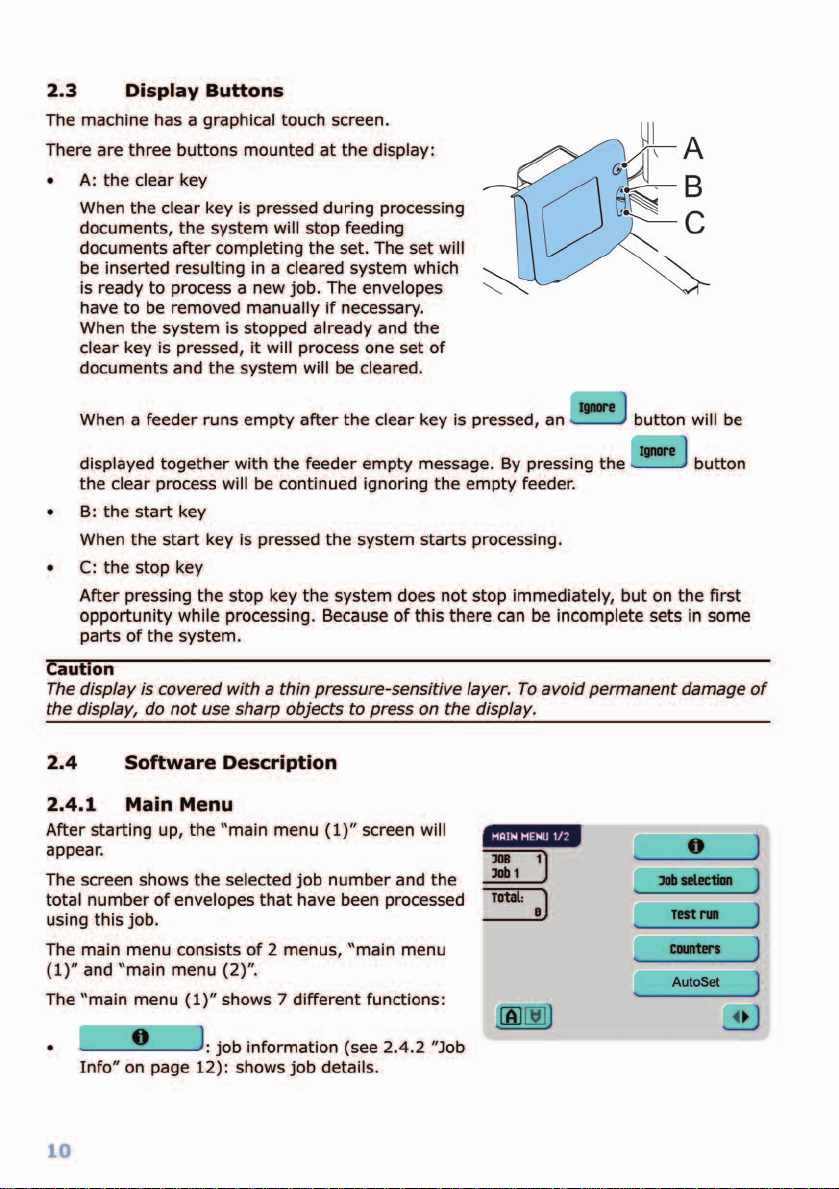
2.3 Display Buttons ...................................................................... 10
2.4 Software Description ....................... .. ... .. ................................. 10
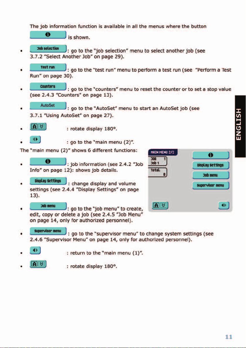
2.4.1 Main Menu ................................................................... 10
2.4.2 Job Info ...................................................................... 12
2.4.3 Counters ..................................................................... 13
2.4.4 Display Settings ........................................................... 13
2.4.5 Job Menu ..................................................................... 14
2.4.6 Supervisor Menu ............................. ...................... .. ..... 14
3 Operating Instructions .................................................................. 20
3.1 Installation ............................................................................ 20
3.2 Preparation ........................................................................... 20
3.2.1 Document Feed Trays ................................................... 20
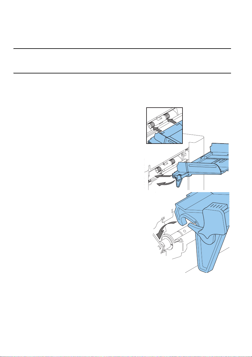
3.2.2 Conveyor Stacker ......................................................... 21
3.3 Starting Up ............................................................................ 21
3.4 Loading Documents ................................................................ 22
3.4.1 Document Orientation ................................................... 22
3.4.2 Side Guides ................................................................. 23
3.4.3 Document Separation .................................................... 23
3.4.4 Filling the Document Feed Tray ...................................... 24
3.4.5 Adjustment of the Document Stoppers ............................ 24
3.5 Loading Envelopes .................................................................. 25
3.5.1 Adjusting Side Guides ................................................... 25
3.5.2 Envelope Separation ..................................................... 25
3.5.3 Feeding Envelopes ........................................................ 26
3.6 Sealing Envelopes .................................................................. 26
3.7 Job Selection or AutoSet
...................................................... 27
3.7.1 Using AutoSet .............................................................. 27
3.7.2 Select Another Job ........................................................ 29
3.8 Run the Daily Mail .................................................................. 30
3.9 Create a Job .......................................................................... 31
3.9.1 Job Settings ................................................................. 32
3.9.2 Envelope Settings ......................................................... 32
3.9.3 Document Settings ....................................................... 33
3.9.4 Fold Settings ................................................................ 34
3.9.5 Optical Mark Recognition Settings (Option) ...................... 36
3.9.6 Double Feed Control Settings ......................................... 37
3.9.7 Job Name .................................................................... 38
ENGLISH
1
Page 4

3.9.8 Mailing/Franking Settings (Option) .................................. 39
3.10 Edit a Job .............................................................................. 40
3.11 Copy a Job ............................................................................ 40
3.12 Delete a Job .......................................................................... 41
4 Options..................................................................... ......... ............ 42
4.1 Activate an Option .................................................................. 42
4.2 Optical Mark Recognition (OMR) ............................................... 42
4.2.1 General ................ ........................... ............................ 42
4.2.2 Alignment .................................................................... 43
4.2.3 Document Orientation ................................................... 44
4.2.4 OMR Codes .................................................................. 44
4.3 Online Services ...................................................................... 48
4.3.1 General ................ ........................... ............................ 48
4.3.2 Start-Up Online Services ............................................... 48
4.3.3 Connection .................................................................. 48
4.3.4 Messages ................................................................... 49
4.3.5 Configuration Menu ....................................................... 50
4.4 Production Feeder................................................................... 51
4.4.1 Function ...................................................................... 51
4.4.2 Preparations ................................................................ 51
4.4.3 Adjust Side Guides ....................................................... 52
4.4.4 Document Separation .................................................... 52
4.4.5 Feeding Documents ...................................................... 52
4.5 insert’n Frank™ (insert’n Mail) ................................................. 53
5 Maintenance .................................................................................. 54
5.1 Operator Maintenance ............................................................. 54
6 Fault Finding.................................................................................. 55
6.1 Error Messages ...................................................................... 55
6.2 Clearing Stoppages ................................................................ 56
6.2.1 Exit, Sealing and Inserting Area ..................................... 56
6.2.2 Envelope Hopper .......................................................... 57
6.2.3 Lower Envelope Track ................................................... 57
6.2.4 PowerFold
6.2.5 FlexFeed
® ............................................................................................................................ 58
® ............................................................................................................................... 58
6.2.6 Collating Area .......................... ....................... .. ........... 58
6.3 Operator Troubleshooting ........................................................ 58
7 Specifications .............................................................................. .. 62
7.1 Technical Specifications ........................................................... 62
7.2 Configuration Dimensions ........................................................ 62
7.3 Other Specifications ................................................................ 62
7.4 Document Specifications ......................................................... 62
7.5 Envelope and Insert Specifications ............................................ 63
8 Terminology .................................................................................. 65
Index.............................................................................................. 72
2
Page 5

1. HEALTH, SAFETY AND ENVIRONMENT
1.1 Precautions and Safety Issues
Thoroughly read this operator manual, before using this machine.
Warnings
• If the feed/fold unit and inserter unit have to be physically separated, the operator
should pay attention to the heavy weight of the unit during separation.
• Before connecting check whether the system is suitable for the local mains voltage.
Refer to the type plate.
Safety Precautions
• Only competent personnel should operate this machine.
If incompetent personnel do operate this machine, the manufacturer does not accept
responsibility for any resulting accidents or injuries.
• Only skilled persons, who are aware of the risks involved, may open the protective
covers.
For safety reasons, the machine will not function when the covers are open.
• Keep long hair, fingers, jewelry, etc. away from rotating and moving parts.
• The power connection must be easily accessible, preferably close to the machine.
• For safety reasons, it is essential that the machine is connected to a socket outlet that
has a protective earth connection.
• Over-current protection in the equipment also relies on the branch circuit protection
(max. 20 A).
• The following part(s) is (are) considered the equipment disconnect device(s):
- Power supply cord plug
- 12-pole connector, located on the right-hand side
ENGLISH
3
Page 6

Conventions
Warning
This symbol:
• Identifies situations where improper use of the machine can result in
personal injury or permanent/catastrophic damage to the machine.
• Indicates that the operator manual should be consulted.
Warning
This symbol indicates a danger caused by high voltage.
Note
A note gives additional relevant information.
.
4
Page 7

5
Page 8

2. FUNCTIONAL DESCRIPTION
The 6402 Series feeds, folds and inserts documents into envelopes and then seals and stacks
the envelopes. Automatic monitoring ensures the correct number of inserts per envelope.
The machine is a sophisticated folding and inserting system which can process large
quantities of mail rapidly and easily. The system can be operated by means of a user
friendly interface.
The settings of the system (types of documents, type of envelopes and the type of fold) is
recorded in so-called jobs. These jobs can be programmed by an authorized user.
The 6402 Series is equipped with a variety of special features as document thickness detection,
programmable jobs,
AutoSet, double feed control, hopper swap, multifeed, and daily mail.
6
Page 9
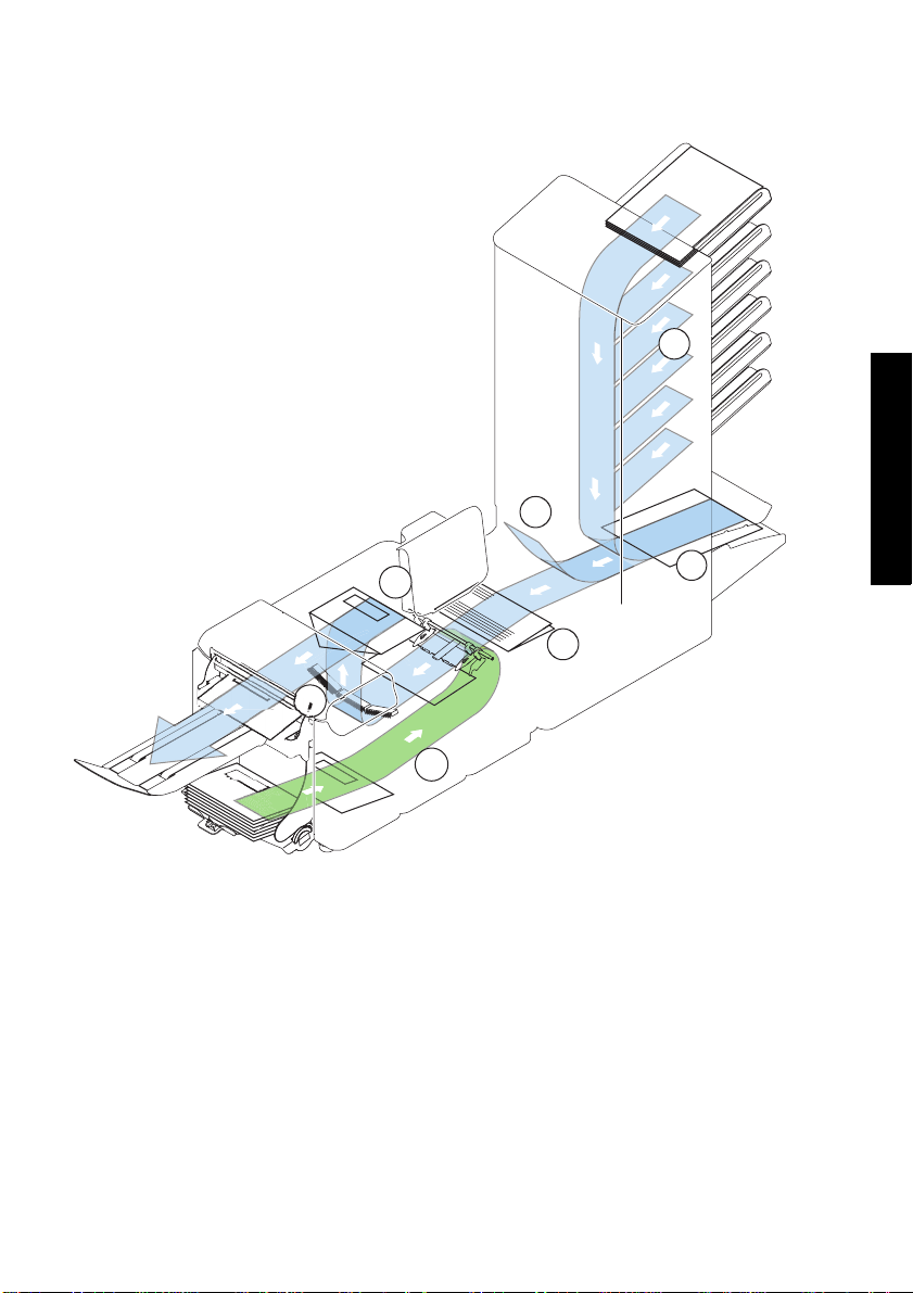
2.1 Overview
The system consists of the following parts:
1. FlexFeed®
2. Collating area
3. Divert Deck
4. Folding area
5. Envelope feeder
6. Inserter
7. Envelope exit (including conveyor
stacker)
1
3
2
6
4
7
5
2.1.1 FlexFeed® (1)
The flexFeed® is the feeding part of the system. There are two types of feeders available:
the automatic and the special feeder. The automatic feeder does not require any
adjustments for the separation. The flexFeed
this way the system can detect faulty sets o f documents. The flexFeed
hopper swap. This means that two feeders can be linked as pairs. When the first feeder is
empty , the system switches to the other feeder . Meanwhile the other empty feeder can be
refilled without stopping. It’s also possible to feed multiple documents from one feeder. In
this way more documents can be fed from one station, for example an original and a copy
of a document.
®
is equipped with double feed control. In
®
is equipped with
ENGLISH
7
Page 10

The upper automatic feeder is equipped with a “daily mail” function for processing
documents or sets of documents which cannot be processed automatically (e.g. stapled).
2.1.2 Collating Area (2)
After feeding, the documents are gathered and aligned in the collating area.
2.1.3 Divert Deck (3)
The Divert Deck automatically throws out incorrect sets of documents. In this way the
system does not need to stop. Correct sets will be transported to the Folding area.
2.1.4 Folding area (4)
The Folding area folds the documents. The following fold types are possible:
•No fold
•Single fold
• Letter fold
• Zig-zag fold
• Double parallel fold
2.1.5 Inserter (6)
After folding the documents are transported to the inserter unit where the documents are
inserted into a waiting envelope. The inserter then seals the envelope (or not) and stacks
them on the conveyor stacker. Automatic monitoring ensures the correct number of
inserts per envelope.
8
Page 11
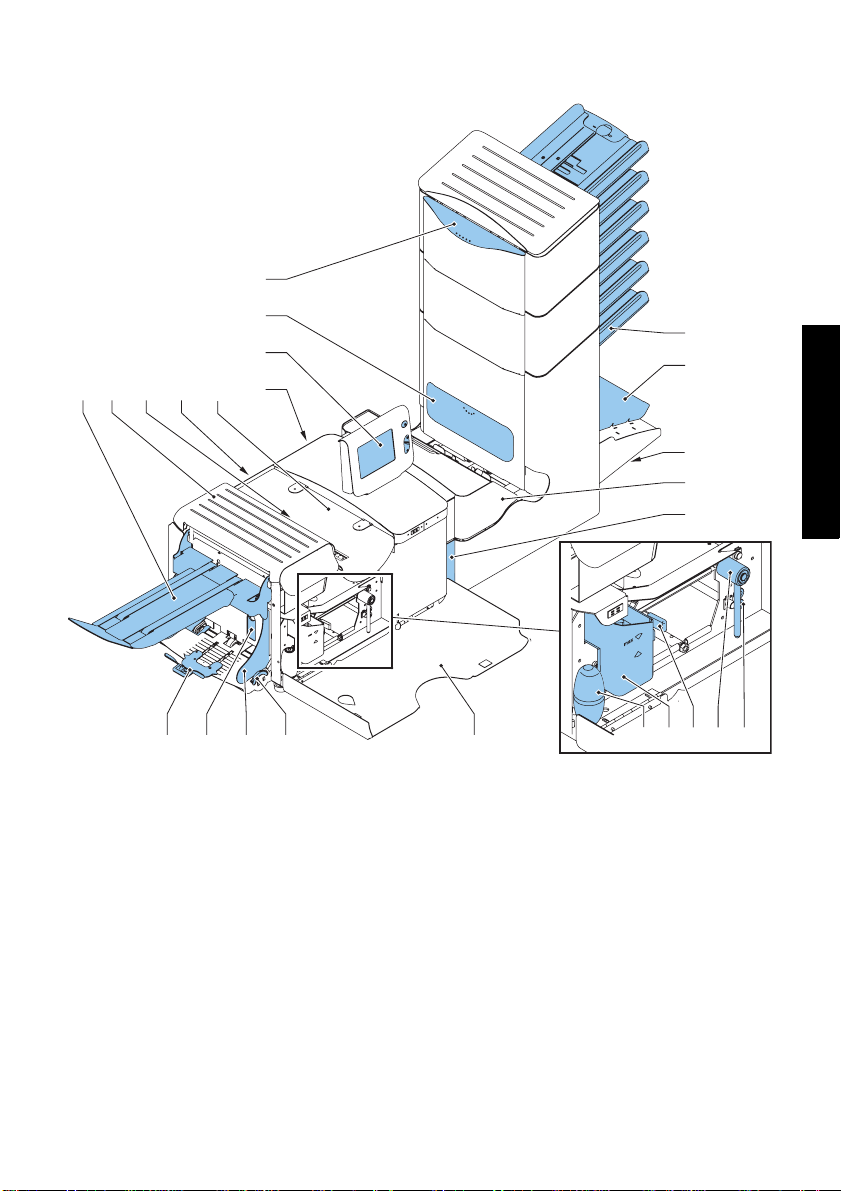
2.2 Operating Controls
I
H
G
A B D
C
F
E
U TVWX
A conveyor stacker
Bloc cover
C unlocking lever for loc
D power inlet, power switch
Einserter cover
F RS232 connector / USB / modem
G display (operator panel)
H OMR reading head cover
I hand grip vertical transport cover
J document feed tray
Kcollator arm
L operator manual storage space
M folding area
J
K
L
M
N
S
N locking handle
O air plugs for cle aning the sensors
P handle for manual envelope transport
Q unlocking handle for rollers envelope
track
R water reservoir
S bellows for cleaning sensors
T side cover (opened)
U thumb wheel for side guide adjustment
V side guides envelope feed tray
W lever for envelope separation
adjustment
X envelopes support
OPQR
ENGLISH
9
Page 12
Page 13
Page 14
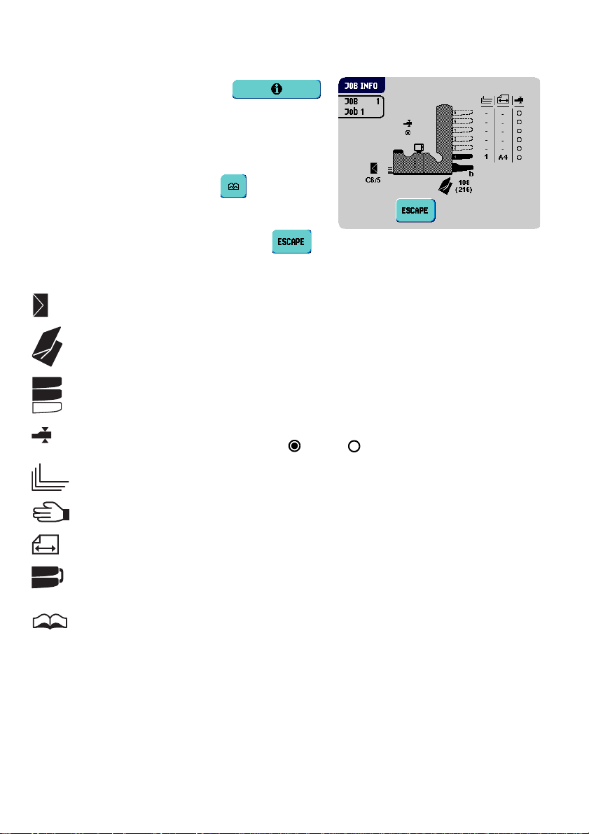
2.4.2 Job Info
To enter the “job info” menu, press .
This menu displays all relevant information about
the selected job.
If the optional OMR is used the "1 track OMR info"
menu is also available using the button.
To return to the “main menu (1/2)”, press .
The “job info” menu contains the following information:
Gives information about the envelope size (ISO format or height in mm).
Shows the type of fold.
3
2
1
Shows the feeders selected to pick documents from (black is selected).
The sign below this icon shows if the document double feed detection for the
relevant feeder is switched on - or off - .
The number under this icon indicates the number of sheets that must be
picked from the relevant feeder.
This sign indicates that the rele vant feeder is set for daily mail.
Below this icon, the format of the document in the relevant feeder is
3
2
indicated (ISO standard or height in mm).
This sign indicates that the relevant feed ers are linked. This means that
when one feeder is empty, the system automatically starts picking
documents from the other feeder.
The sign indicates that for the relevant feeder the Optical Mark Recognition
(OMR) is switched on (optional).
12
Page 15
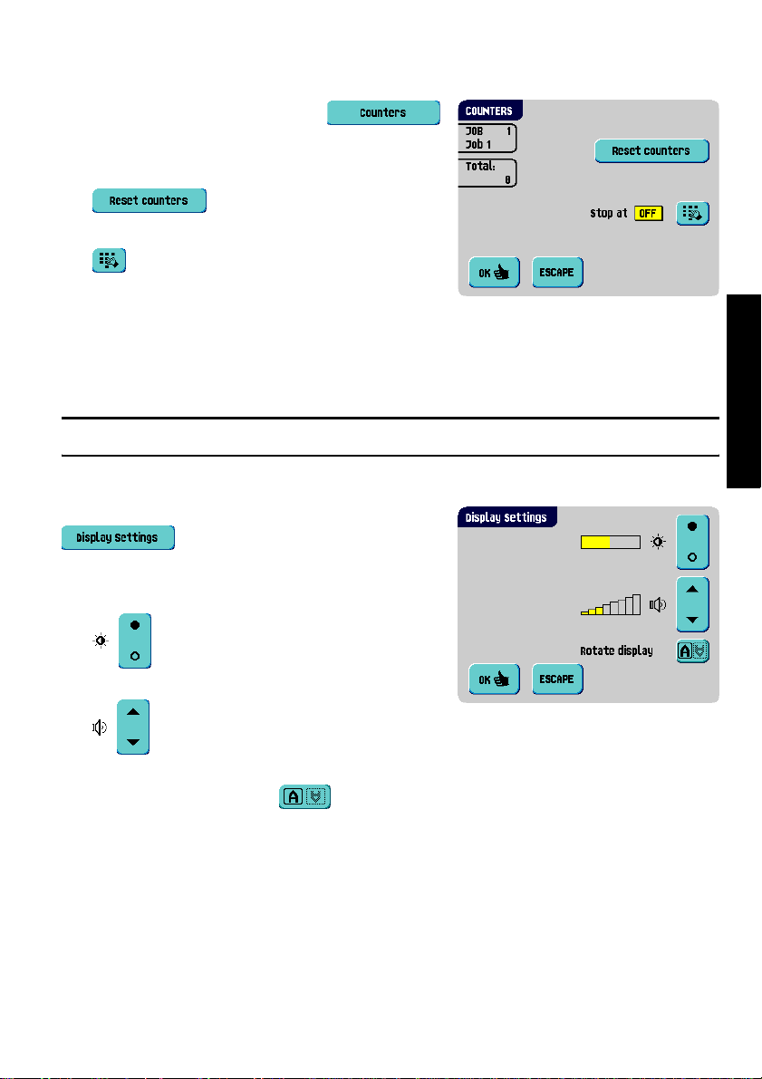
2.4.3 Counters
T o enter the “counters” menu, press
from the “main menu (1)”.
The “counters” menu shows the following functions:
• : press this button to reset the
daily job counter and stop counter to zero.
• : press this button to enter a
stop value.
The stop counter is switched off when it is set to
zero. The display will show “Stop at off”.
The stop counter can be set between 0 (switched off) and 9999. The system will continue
until the job counter reaches the stop counter value. The system stops and can be restarted.
Note
The counter settings are job related.
2.4.4 Display Settings
To enter the “display settings” menu, press
from the “main menu (2)”.
The “display settings” menu shows the following
functions:
• : enables to change the contrast of the
display. The graphic shows the contrast setting.
• : enables to adjust the volume of the
acoustic signals. The graphic shows the volume setting.
• Rotate display: press the button to rotate the display 180 °.
ENGLISH
13
Page 16
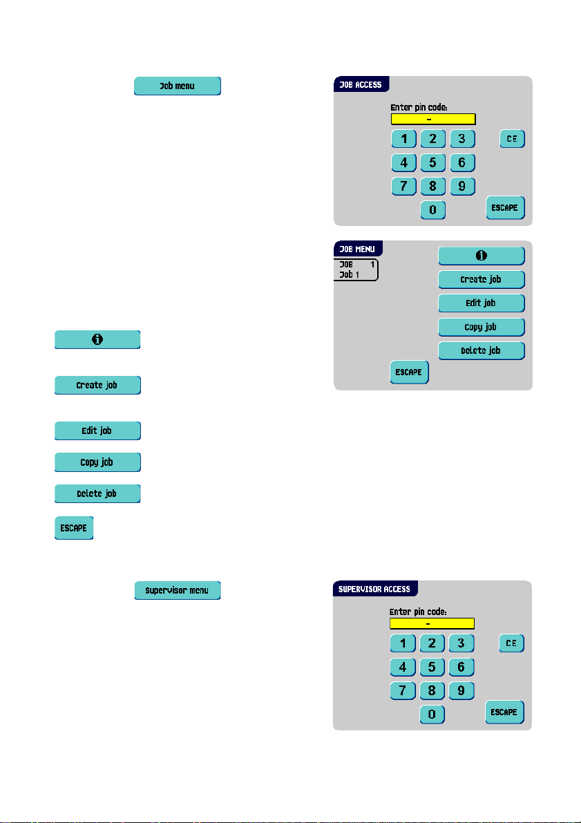
2.4.5 Job Menu
After pressing the button a login
menu opens.
To prevent jobs being edited or deleted without
informing the ‘job owner’, this menu is protected by
a PIN-code. The PIN-code is
When a wrong pin code is entered, the cursor is set
to the first number to try again.
After 3 times entering a wrong pin code the display
shows the “main menu (1)” again.
After entering the correct pin code the “job menu”
appears.
This menu enables the creation, deletion and/or
editing of jobs.
The “job menu” shows the following functions:
• : job information (see 2.4.2 ”Job
Info” on page 12).
• : create a job (see 3.9 ”Create a
Job” on page 31.)
• : edit a job (see 3.10 ”Edit a Job” on page 40).
2546
.
• : copy a job (see 3.11 ”Copy a Job” on page 40).
• : delete a job (see 3.12 ”Delete a Job” on page 41).
• : exit and return to the “main menu (1)”.
2.4.6 Supervisor Menu
After pressing the button a login
menu opens.
Enter the PIN-code 2546 to access the “supervisor
menu”.
14
Page 17
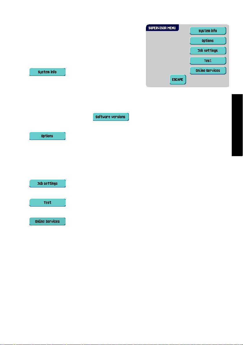
After entering the correct pin code the “supervisor
menu” appears.
This menu enables checking and configuring the
system.
The “supervisor menu” shows the following
functions:
• : shows system information,
like:
- The flex certificate, used for OMR
- The counter since last visit: the counter value since the last service visit
- The last error generated by the system
The screen shows a button : this shows the software versions that are
present in the total system.
• : shows option information and system information:
-The chip ID
-The system ID
- The installed options
For installing new options, see 4.1 ”Activate an Option” on page 42.
• : opens the “job settings” supervisor menu (see ”Job Settings
(Supervisor)” on page 16). From this menu system parameters can be set.
• : opens the “test menu” (see ”Test” on page 18). Use this menu to
test the system.
• : opens the “Online Services” menu ( option, see 4. 3 ”Online Services”
on page 48). This screen enables to connect the system to a server and receive
messages.
ENGLISH
15
Page 18
Job Settings (Supervisor)
Caution
Job settings normally will be changed by a service engineer only. Therefore first consult
the supplier’s Helpdesk before changing any settings. Changes to the job settings can
result in malfunctioning of jobs.
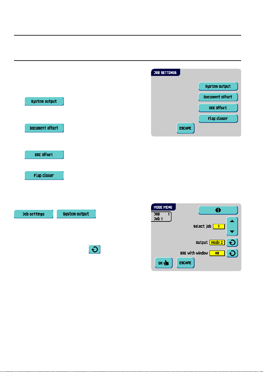
The “job settings” menu (supervis or) can be o pened
from the “supervisor menu”. From this menu system
parameters can be set. The “job settings” menu
shows the following functions:
• : opens the “mode menu” to set
the output mode for a job (see ”Mode Menu” on
page 16).
• : opens the “document offset”
menu to set the document offset in a set of
documents for a job (see ”Document Offset” on page 17).
• : opens the “BRE offset” menu to set the BRE offset on or off (see
”BRE Offset” on page 17).
• : opens the “flap closer” menu (see ”Flap Closer” on page 18). Use
this function to improve the envelope sealing process.
Mode Menu
When selecting from the “supervisor menu”
, , the “mode menu”
appears.
In this menu for each of the jobs 1 through 25 and
AutoSet a choice can be made between output
Mode 1 and Mode 2 using the button. Mode 2 is
the default setting.
Mode 1 focuses on the versatility of paper
parameters (paper thickness; document length), i.e.
correct operation under even extreme paper conditions.
Mode 2 focuses on high speed and is achieved as follows:
• During multi feed (more than one page from one feeder) the movement on the
collator is minimal. In mode 1 the divert unit will be used for completing the collating
process (less paper on paper transport).
• During the transportation of a set from the co ll ator into the powerFold
is going into the collator already. This results in temporary overlapping sets with two
different transport directions. In mode 1 the set has left the collator completely before
the next set enters the collator.
®
, the next set
16
Page 19
• Anticipation call for the envelope is used. That means that a (folded) set is leaving the
flexFeed
envelope is on the insert position already before the set leaves the flexFeed
It is advised to use Mode 1 with a paper thickness of 65 g/m
of 12 inch (305 mm) or higher, and for situations where Mode 2 is not functioning
properly. In all other cases Mode 2 is advised.
If you select Mode 2, select if the reply envelope has a window or not.
®
already before the envelope is ready on the insert position. In mode 1 the
2
or less, a document length
®
.
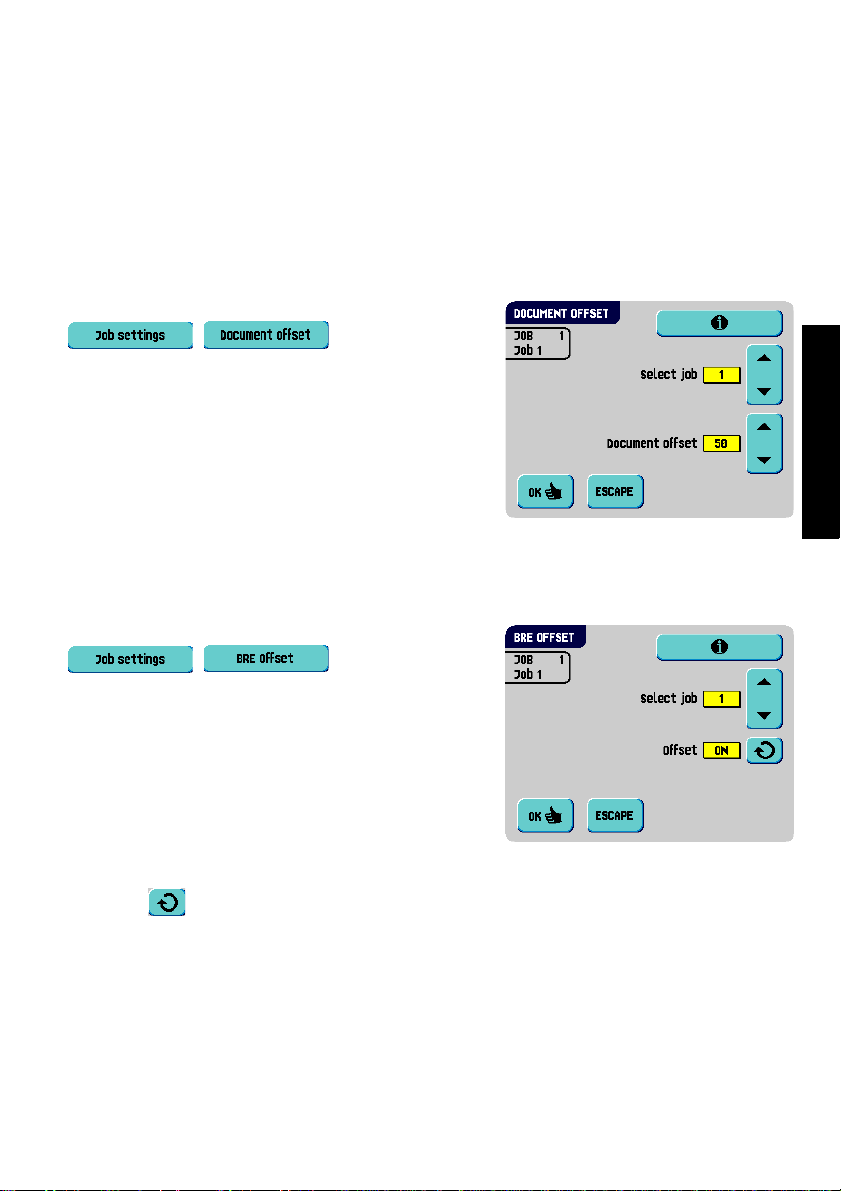
Document Offset
When selecting from the “supervisor menu”
, , the “document
offset” menu appears.
The vertical transport of documents fed by the
various feeders is arranged in such a way that the
documents are partially overlapping each other. This
overlapping scheme ensures that the documents are
properly aligned in the collator area.
In the “document offset” menu you can set the
extend to which the documents are not overlapping
each other, i.e. the document offset value. The default value is 50 mm (2.0 inch). The
document offset can be varied between 20 mm (0.8 inch) and 75 mm (3.0 inch).
BRE Offset
When selecting from the “supervisor menu”
, , the “BRE offset”
menu appears.
If a document is longer than the set address fold but
shorter than the envelope height, this document
sometimes will be unnecessarily folded. Under
certain conditions this document can be prevented
from being folded. This can be implemented with the
menu “BRE offset” (BRE means Business Reply
Envelope).
ENGLISH
For each of the jobs 1 through 25 and AutoSet
using the button.
In the case of offset “on” the last docume nt that was added to the set will be shifted from
the rest of the set (offsetting). This document will be held back during a certain distance.
This means that the trailing edge of this upper document leaves the collator at last. This
document will not be folded. During the insertion into the envelope the documents of the
set will be realigned.
an offset can be switched on or off
17
Page 20
The conditions are:
• The feeder that supplies this upper document (BRE) is set to one document per set
(no multi feeding).
• The document directly beneath this document must be at least 60 mm (2.4 inch)
longer than the BRE.
• The upper document must be longer than the set address fold.
• The folding mode is either single fold or letter fold (no Z-fold).
• The upper document must be shorter than the envelope height.
Note
It is possible to use the BRE offset for a BRE and an enclosure (card) in one set. The extra
condition is that this enclosure is equal to or smaller than the set address fold and should
be placed direct underneath the BRE in the set.
The whole BRE offset is based on friction between documents within a set. Therefore it is
necessary to make use of these conditions to reduce the risk of bad transporting, folding
and inserting.
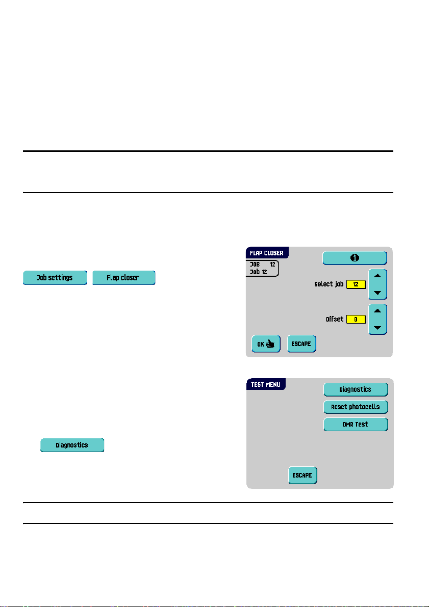
Flap Closer
When selecting from the “supervisor menu”
, , the “flap closer”
menu appears. Use this function to improve the
envelope sealing process for a job. The offset can be
varied between -20 and 20. If for example the offset
is set to +10 the sealing process will be activated 10
pulses later than initially.
For each of the jobs 1 through 25 and AutoSet
an offset can be set.
Test
The “test menu” menu can be opened from the
“supervisor menu”. Use this menu to check the
system, reset all photocells and execute an OMR
test. The menu consists of the following functions:
• : use this function to check if all
motors, clutches and sensors are correctly
connected. This test derives the status of the
actuators and clutches by briefly activating the
actuators and then measuring the current.
Note
Remove all paper and close all covers before testing.
18
Page 21
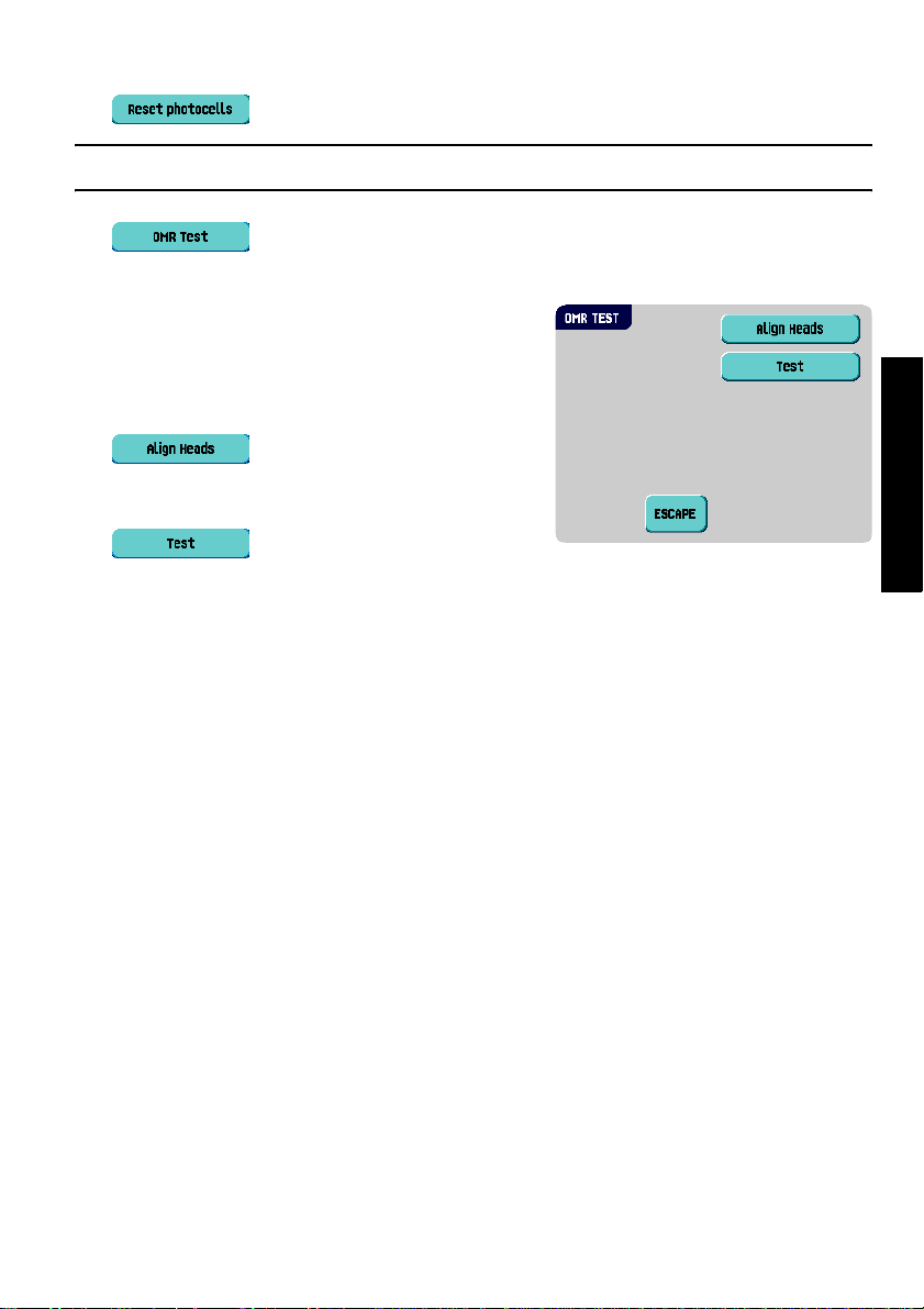
• : use this function to calibrate all photocells.
Note
Remove all paper and close all covers before calibration.
• : use this function to align and test t he OMR readi ng he ad (see ”OMR
Test” on page 19).
OMR Test
The “OMR test” menu can be opened from the “test
menu”. Use this menu to align and test the OMR
reading head (see ”Reading Head Position” on page
43). The menu consists of the following functions:
• : align the OMR reading head.
Put a document with reading marks in the
feeder and press this button.
• : shows the mark quality and the
number of read marks from the last processed document. Also the gain of the OMR
amplifier is shown.
ENGLISH
19
Page 22
3. OPERATING INSTRUCTIONS
3.1 Installation
Caution
You can severely damage the machine if it is connected to the incorrect power supply.
Before plugging in the machine, check if the local voltage is the same as the voltage
mentioned on the type plate.
3.2 Preparation
3.2.1 Document Feed Trays
Place the document feed trays in position:
1. Hold the document feeder slightly inclined as
shown in the figure.
2. Place the front end of the document feed tray
underneath the two black rollers.
3. Move the document feed tray upwards (lifting
the black rollers), until it is possible to ‘hook’ the
feeder into place.
4. Move the document feed tray towards the
machine and move the hooks over the mounting
points (on both sides).
5. Let the document feed tray rest on the machine.
20
Page 23
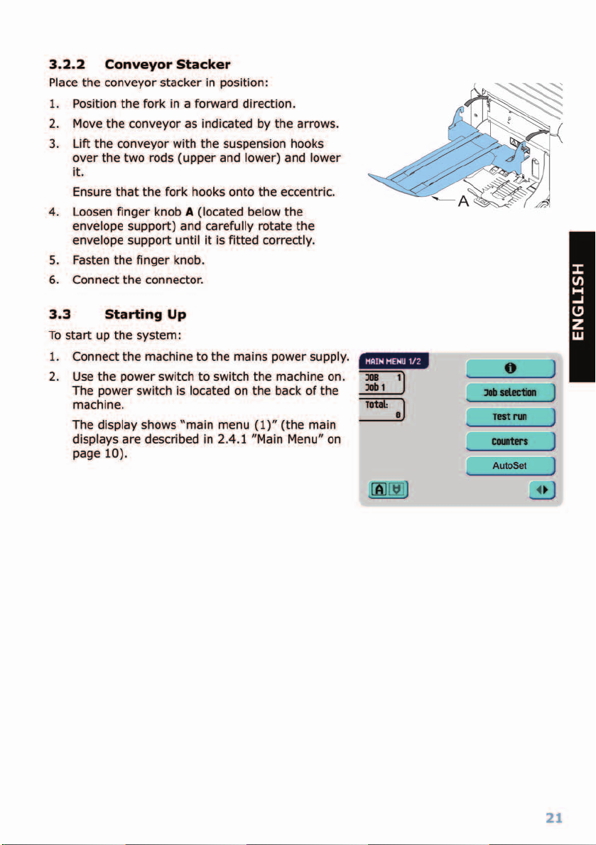
Page 24

3.4 Loading Documents
3.4.1 Document Orientation
Fold type
no fold single fold
Type of documents
hopper swap two documents document + enclosureone document
letter fold
zig-zag fold
double
parallel fold
Address carrier in top feeder.
Face up and leading.
Address carrier in bottom feeder.
Face down and trailing.
Address carrier in top linked
pair feeders.
Face up and leading.
Address carrier in bottom linked
pair feeders.
Face down and trailing.
Address carrier in top feeder.
Face up and leading.
Address carrier in bottom feeder.
Face down and trailing.
Address carrier in top feeder.
Face up and leading.
Address carrier in top feeder.
Face down and trailing.
In case the optional extended powerFold® is installed, the following feeding rules apply to
documents with bottom address position:
Type of documents
two documents document + enclosureone document
Address carrier in top feeder.
Face up and trailing.
Address carrier in top feeder.
Face up and trailing.
Fold type
no fold single fold
zig-zag fold
Address carrier in top feeder.
Face up and leading.
hopper swap
Address carrier in top linked
pair feeders.
Face up and trailing.
22
Page 25

3.4.2 Side Guides
To adjust the side guides it is best to remove the
document feed tray from the feeder as follows:
1. Push handle
2. Lift the document feed tray upwards to unhook
it and then pull it out from the feeder.
A
downwards.
A
3. Loosen the knob
4. Grab the side guides in the middle and push
them apart as far as possible.
5. Put a small stack of documents between the side
guides.
6. Grab the side guides in the middle and push
them towards the documents.
The space between the side guides and the
documents should be such that the documents
have just enough play to move freely.
7. Re-tighten knob
8. Remove the stack of documents.
9. Replace the document feed tray (3.2.1 ”Document Feed Trays” on page 20).
B
half a turn.
B
.
ENGLISH
B
3.4.3 Document Separation
The term ‘Document separation’ refers to the adjustment required for separating the
upper document from the rest of the documents in the stack. This prevents picking up to
much documents from the stack at the same time.
The document separation for the automatic feeders is set automatically. There are no
manual adjustments needed.
23
Page 26

The document separation for special feeders must
be adjusted manually as follows:
1. Push the knob
2. Open the left-hand side guide
downwards.
3. Place a document on the feed tray and slide it
about 60 mm (2.4 inch) into the system (turn
the knob
set to narrow).
4. Push the document between the separation
rollers, which are behind the rubber paper
pullers.
5. Turn the knob
resistance or counter clockwise to lower the
resistance.
The separation is adjusted correctly when a slight resistance is felt on the document.
6. Pull the knob
7. Close the left-hand side guide.
B
forward until it clicks.
A
by turning it
B
counter clockwise if the separation is
B
clockwise to get more
B
back again when ready.
A B
3.4.4 Filling the Document Feed Tray
Fill the document feed tray as follows:
1. Open the left-hand side guide A by turning it downwards.
The feed rollers will automatically be lifted.
2. Place a stack of documents between the side guides.
3. Turn the left side guide upwards again.
4. Feed the documents (depending on the type of documents and the type of fold) as
shown in 3.4.1 ”Document Orientation” on page 22.
3.4.5 Adjustment of the Document Stoppers
The document stoppers mark the position at which the documents coming from the feeder
turn towards the folding area. The position of the document stoppers is automatically
determined by the system during the job programming.
24
Page 27

Initially the document stoppers are adjusted for
position B. In this position a wide variety of
documents can be handled (max. 297 mm; 11.7
inch) and adjustment is not needed.
When a job is selected in which a different stopper
position has been programmed, the operator has to
put the document stoppers in the correct position as
indicated by the display.
To adjust the stopper position:
1. Lift and hold the collator arm
2. Squeeze the stopper and pull the front side tab
up.
To replace the stopper:
1. Place the flat back tab into the slotted hole.
2. Push the stopper into position.
A
Stop position
handle documents up to 297 mm (11.7 inch) and stop position
up to 356 mm (14 inch).
can handle documents up to 148 mm (5.8 inch), stop position B can
D
.
3.5 Loading Envelopes
3.5.1 Adjusting Side Guides
Adjust side guides C by rotating thumb wheel D, so
that the envelopes:
• Fit exactly between the side guides
• Can move freely
Note
If the distance between the side guides is too large,
the envelopes will twist sidewards, when transported
into the machine.
C
B
A
B
C
D
C
can handle documents
ENGLISH
3.5.2 Envelope Separation
To set the envelope separation:
A
1. Pull down small lever
2. Insert one envelope up to the stoppers.
A
3. Return lever
Now the envelope separation is set.
.
.
DCA
25
Page 28

3.5.3 Feeding Envelopes
1. Place the bottom envelope between the rollers
(flap down and trailing - bottom side of envelope
pointing to the machine).
2. Loosen the stack of envelopes and place the
stack on top of the bottom envelope.
3. Shift envelope support B in or out, so that the
flap side of the envelope is lifted approximately
20 mm (0.8").
4. Turn envelope support B so the weight of the
envelopes is distributed evenly on both sides.
3.6 Sealing Envelopes
Note
Refer to 5.1 ”Operator Maintenance” on page 54 as well.
Switch the envelope sealing on or off:
1. Lift the handgrip to open the top cover.
2. Shift the blue handle A towards to disable
the envelope sealing or towards to enable
the envelop sealing.
3. Close the top cover.
B
When the sealing of the envelopes is enabled, the
sealing liquid reservoir must be filled:
1. Open the front cover A.
2. Fill the reservoir B to the “Max” level indication
with sealing liquid.
3. Close the front cover A.
Before starting the job, wait approximately 5
minutes for the brushes to moisten.
26
A
B
A
Page 29

Page 30

Insert Position
Note
This adjustment must only be checked in case of problems or when changing the envelope
type.
1. Lift the locking lever of the loc and pull the loc
into the vertical position.
The flap folding line must be positioned under
the green indicator
position as follows:
2. Press on the left or right side of to
adjust the insert position to the left or t he right.
Each button stroke stops the next envelope
0.5 mm (0.02 inc h) to the right (earlier) or to
the left (later).
3. Press to load a new envelope into the insert position.
4. Recheck the insert position, and adjust as required.
If necessary adjust the envelope insert fingers, see ”Adjust the Envelope Insert
Fingers” on page 28.
C
. If not, adjust the insert
Adjust the Envelope Insert Fingers
To adjust the envelope insert fingers:
D
1. Loosen the knurled knob
2. Adjust each finger so that the tip enters about 5 mm (0.2 inch) into the envelope.
3. Re-tighten the knurled knob.
The fingers can be moved sideways to the desired position.
Caution
When adjusting the fingers sideways, be sure that finger A is not positioned over sensor
B
. When an incorrect finger position is adjusted the display shows an error screen.
on top of each finger.
4. Place the outer fingers about 5 to 10 mm (0.2 to 0.4 inch) from the edges of the
envelope.
Check the position of the insert fingers when changing to a different type of envelope.
Address Position
When the envelope position and the position of the fingers is correct:
1. Press to load a folded sheet into the envelope.
The envelope will be sealed (when enabled, refer to 3.6 ”Sealing Envelopes” on page
26) and ejected to the conveyor stacker.
2. Check the position of the address in relation to the address window in the envelope.
28
Page 31

3. If necessary, press the Up or Down button to adjust the address position.
Each key stroke brings the address 1 mm (0.04 inch) with a maximum of 12 mm
(0.48 inch) lower or higher.
If the required address position is beyond the maximum range of 24 mm (0.96 inch),
the AutoSet function can not be used. Use a programmed job instead.
4. Press to make another test run.
5. Recheck the position of the address, and adjust as required.
6. Press to leave this screen to return to the “main menu (1)” or press the
button to immediately start the job.
Starting the Job
To start a job:
1. Press the button to start the job.
During running the display shows the “inserting” menu.
2. Press the button to stop the job. The machine will stop immediately.
3. Press the button to clear the document path to prepare the machine for a new
job.
When an AutoSet
the copy function in the job menu (see 3.11 ”Copy a Job” on page 40) to store the
settings.
job is defined successfully these settings can be stored into a job. Use
ENGLISH
3.7.2 Select Another Job
To select another job:
1. Press to select another
predefined job.
2. Press the arrows to select another job number.
The screen shows the job options of the relevant
job (see 2.4.2 ”Job Info” on page 12).
3. Press to confirm the selected job.
29
Page 32

Perform a Test Run
To perform a test run:
1. Press to display the “test run”
menu.
A message can appear: “Set manual feeding” or
“Set automatic feeding”. In that case:
a Check if the daily mail handle is in the
correct position (see 3.8 ”Run the Daily
Mail” on page 30).
b Correct if necessary.
c Press the button.
d Press again.
The “test run” menu displays.
2. Press to load a new envelope into the insert positio n . This gives the
possibility to check and correct the insert position of the envelope (see ”Insert
Position” on page 28).
3. When the envelope position and the position of the fingers is correct, press
to load a folded sheet in the envelope.
The envelope will be sealed (when enabled, refer to 3.6 ”Sealing Envelopes” on page
26) and ejected to the conveyor stacker.
When finished testing start the job (see ”Starting the Job” on page 29).
3.8 Run the Daily Mail
To process documents or sets of documents, which can not be processed automatically
(e.g. stapled documents), the top feeder is equipped with a daily mail switch.
To switch to the daily mail function:
1. Select a job where the daily mail function has been set to on:
a From the “main menu (1)”, press .
b Search for a job with the daily mail function using the arrows. The daily mail
function can be recognized by the icon in the “job info” screen.
c Press to select the job and return to the “main menu (1)”
30
Page 33

2. Turn left side guide A of the upper tray down.
The Daily Mail handle B will become visible.
3. Move the handle to to enable the Daily
Mail function.
4. Turn left side guide A upwards.
5. Place the document or document set in the
feeder.
If necessary adjust the side guides (see
3.4.2 ”Side Guides” on page 23).
B
6. Press the button to start the job.
The document or document set will be folded and inserted in the envelope as
described in the selected job.
7. Place the following document or document set in the feeder. The machine will keep
running to process the inserted document or document set.
8. When finished with Daily Mail, press the button to stop the job.
9. Turn left side guide A down.
10. Move the Daily Mail handle to the ‘AUTO’ position to disable the Daily Mail and to
enable the automatic document separation.
A
3.9 Create a Job
To create a new job:
1. Press from “main menu (2)” (see 2.4.1 ”Main Menu” on page 10).
2. Enter the pin code.
The “job menu” opens (see 2.4.5 ”Job Menu” on
page 14).
3. Press .
The “create job” menu appears. The new job
must be stored under a job number. The screen
will show the lowest free job number.
Press the arrows to select a higher or lower free
job number (if available).
ENGLISH
4. Press to confirm the selected free job number.
The “job settings” screen opens. The meaning of all buttons and settings will be
explained in 3.9.1 ”Job Settings” on page 32.
31
Page 34

5. Press to save the job with the entered settings under the sp ecified job number
and name.
To name a job, see 3.9.7 ”Job Name” on page 38.
6. Press to perform a test run with the new job settings (see ”Perform a
Test Run” on page 30).
Note
A new selected job number starts with default settings.
3.9.1 Job Settings
From the “job settings” menu the followin g settings
are available:
Envelope settings (see 3.9.2 ”Envelope
Settings” on page 32)
Document settings (see 3.9.3 ”Document
Settings” on page 33)
Fold settings (see 3.9.4 ”Fold Settings” on
page 34)
Optical Mark Recognition (OMR) settings (if
installed) (see 3.9.5 ”Optical Mark
Recognition Settings (Option)” on page 36)
Double feed control settings (see
3.9.6 ”Double Feed Control Settings” on
page 37)
Job name settings (see 3.9.7 ”Job Name” on
page 38)
Mailing/Franking settings (if installed) (see
3.9.8 ”Mailing/Franking Settings (Option)”
on page 39)
3.9.2 Envelope Settings
In this screen the properties of the used envelopes
must be entered.
In the top of the screen, two selection buttons are
displayed, from which one can be selected. The
selected settings button will be highlighted yellow.
• Press to select an envelope size . Use the
button to enter the applicable dimensions.
It is also possible to select ISO standard
envelopes or dimensions in inches (depends on
the installation settings).
32
Page 35

The envelope height can be set between 90 mm (3.5 inch) and 162 mm (6.38 inch).
• Press to set a job without inserting the documents in envelopes (no envelope
mode). This can be useful for jobs, where documents only have to be sorted and/or
folded.
3.9.3 Document Settings
This screen enables the setting of the document
formats and the number of documents that must be
picked from the different feeders.
• Press to set the number of sheets for the
different feeders.
- Press to select a feeder. The selected
feeder will be highlighted.
- Press the arrows to change the number of
sheets that must be picked from the
highlighted feeder.
When the number of documents is 0, the relevant feeder will be deselected.
Note
When a feeder is set to daily mail the number of documents is always 1 and can not be set
in this screen.
Note
The maximum number of sheets per feeder is 25. When folding is used the maximum set
thickness is 8 sheets in letter fold and 10 sheets (80 gr./m2) in single fold. When using
powerFold
sheets is limited further.
®
and bottom address (see 3.9.4 ”Fold Settings” on page 34) the number of
ENGLISH
• Press to enter the document height. The height or the ISO format of the
document will be displayed next to the relevant feeder.
- Press to select a feeder. The selected feeder will be highlighted.
- Press to display a numeric keypad to enter the exact dimension of the
document.
Dimensions can be entered in mm, inches or as standard ISO paper dimensions
(depending on installation settings). The machine will not allow entering
dimensions outer technica l ranges. The document siz e can be set betw een 90 mm
(3.54 inch) and 356 mm (14 inch). The default document size setting of a new
job is 297 mm (11.7 inch).
33
Page 36

• Press to link two feeders. This function enables to fill two adjacent feeders with
the same documents. When the first feeder is empty, the system automatically swaps
to the other feeder.
- Press to select two adjacent feeders. The selected feeders will be
highlighted.
- Press to link two highlighted feeders.
The will be displayed between the selected feeders.
Note
When linking two feeders, the program will automatically apply the number and format of
the documents of the lowest feeder to the other feeder.
• Press to enter the setting of the Daily Mail function.
This function enables to process documents or sets of documents, which can not be
processed automatically (see 3.8 ”Run the Daily Mail” on page 30). The feeder that is
fit for the Daily Mail function will automatically be selected.
- Press to enable the Daily Mail function. The icon appears behind the
daily mail feeder. If you press again the Daily Mail function will be disabled.
3.9.4 Fold Settings
This screen enables the adjustment of the folding
dimensions and the address type.
If the system is equipped with a third fold table and
turning unit (‘extended powerFold
settings” menu consists of two parts:
• In the first part you can set the Address type.
You can switch between Top and Bottom using
®
’) the “fold
the button. If you choose Address type
Bottom you only have three possible fold
settings left.
After pressing the button the second fold setting screen opens.
34
Page 37

• In the second fold setting screen you can select
the fold type.
The following choices are available:
No fold (no settings required)
Single fold
Letter fold
Double parallel fold
Zig-zag fold
Except when no fold is required, the display shows a simple diagram of the docume nt with
the fold positions. To change the fold positions press next to a fold. Enter the
required position of the relevant fold.
The next table shows possible fold positions:
Fold type Minimum position Maximum position
Single fold 75 mm (2.95")
25 mm (0.98") (extended
®
powerFold
)
Letter fold First fold 75 mm (2.95")
25 mm (0.98") (extended
®
powerFold
)
Second fold Position first fold plus
25 mm (0.98")
Zig-zag fold First fold 75 mm (2.95")
25 mm (0.98") (extended
®
powerFold
)
Second fold Position first fold plus
25 mm (0.98")
Double parallel
fold
First fold 75 mm (2.95")
25 mm (0.98") (extended
®
powerFold
)
Second fold Position first fold plus
25 mm (0.98")
Longest document length
minus 25 mm (0.98")
Longest document length
minus 50 mm (1.97")
Longest document length
minus 25 mm (0.98")
Longest document length
minus 100 mm (3.94")
Longest document length
minus 75 mm (2.95")
Longest document length
minus 50 mm (1.97")
Longest document length
minus 25 mm (0.98")
ENGLISH
Note
The display will indicate when entered positions are out of range.
35
Page 38

3.9.5 Optical Mark Recognition Settings (Option)
For a full function description of Optical Mark
Recognition (OMR), see 4.2 ”Optical Mark
Recognition (OMR)” on page 42. Flex-OMR is also
optional. Flex-OMR can read non-Formax codes.
In the “OMR settings” menu it is possible to enable
or disable the OMR function and to adjust the basic
settings for OMR.
The first “OMR settings” menu covers the following
settings:
• Code type: default is the setting “n one”: OMR i s
disabled.
Change the setting using the button. The following codes are possible:
- 1-track OMR for reading Formax codes
- Flex 1-9 for reading non-Formax codes
• Read from feeder: press the button to select a feeder to activate OMR on.
• Reverse reading: reverse reading means that the insert mark is on the first page of
the set. The system will detect the end of a set by detecting the first page of the next
set. Because of the feeding and collating principal reverse reading has the following
limitations:
- The last mark of the code should be pri nted maximally 85 mm ( 3.3 inch) from the
top.
- Enclosures and selective enclosures cannot be handled.
In case the feeder runs empty the last set is still on the collator because the beginning
of the next set could not be detected. In this case the feeder empty message contains
an function. By pressing the button the set on the collator will be
inserted.
Note
Reverse reading is not available in OMR level 0, 1, 2 and 3.
By pressing the button the next “OMR settings”
menu appears. This menu covers the following
settings:
• 1st mark from top: press to set the
position of the first optical mark, measured from
top of the sheet. The value can be varied
between 15 mm (0.6 inch) and 277 mm
(10.9 inch).
36
Page 39

• Max. sheets: select the maximum amount of sheets in the set of documents using the
arrow buttons.
Note
The maximum number of sheets in a set is 25. When the number of sheets exceeds 8 or
10, depending on the fold, the document can not be folded anymore. In this case, the
maximum length of sheets is 156 mm (6.1 inch) for a C5 envelope. Also make sure that
the fold is set to No fold.
Ignoring this will certainly lead to stoppages.
When the maximum number of sheets exceeds the programmed maximum number of
sheets in a set, the machine stops and error VS:110 will be displa yed. After r emoving t he
set and pressing the button, the machine will start and repeat the proces s until an
insert or divert mark is encountered, error VS:135 (final set part) will be displayed.
By pressing the button the next “OMR settings”
menu appears. This menu covers the following
setting:
• Stop on misread: press to set if the
machine should stop or not on misreading an
optical mark.
When “stop on misread” is set to “yes”, the machine
stops after detecting an OMR misreading. The
incorrect set is diverted. After resetting the machine,
the final part of the set is also diverted and the system starts processing again. The
diverted set(s) should be checked by the operator.
When “stop on misread” is set to “no” the machine does not stop after detecting an OMR
misreading. The incorrect set is diverted. The final part of th e set is also diverted and th en
the machine starts processing again. After detecting 5 OMR mi sreadings in a row, the
system stops and an error code is generated.
ENGLISH
3.9.6 Double Feed Control Settings
This screen enables to set the Double Feed Control
(DFC) settings for the different feeders on or off and
to set the thickness measurement.
To set the DFC for the different feeders:
1. Press the button to select a feeder.
2. Press the button to switch the DFC on -
or off - .
37
Page 40

If the DFC is on you can set Continue on double on or off using the button. If
Continue on double is on (“yes”), the machine will not stop if two sheets are feeded
instead of one. The document-set containing the double sheets will be diverted.
When a job is started, the first document taken per feeder is used for a reference
measurement. When a document is exceeding that reference thickness an error will be
displayed.
Note
When Daily mail is selected, the DFC will be switched off automatically.
To set the thickness measurement:
1. Press the button to select the inserter area.
2. Press the button to switch the thickness measurement on - or off - .
If the thickness measurement is on you can set the measurement area:
3. Press the button.
4. Set the measurement area using the arrow buttons.
The standard position of the measurement area is sufficient for a great variety of
documents. Only when using special types of documents, for example small cards, the
position of the measurement area might be adjusted.
When the set thickness is not corresponding the refere nce v alue an error will be display ed.
3.9.7 Job Name
It is possible to store the job with a meaningful job
name, to easily recognize the job. This name will be
displayed in the Main screen during job selection.
1. Enter a job name using the alpha-numeric
keypad.
2. Press to clear a char ac ter le ft of the cu rso r
position (backspace).
3. Press to clear all entered characters and
start again.
38
Page 41

3.9.8 Mailing/Franking Settings (Option1)
If this machine is connected to a mailing/franking
machine, this option allows you to select the
franking mode.
Press the button to select:
•Pass through
The mailing (franking) machine will let the
envelopes pass through without printing/
franking. Press the button to return to
the “job menu”.
•Franking machine
The mailing (franking) machine will print/frank the envelopes according to the local
mailing (franking) machines settings.
If you press the button a screen appears
in which it is possible to link a mailing (franking)
job to the inserter job. Use the arro w buttons to
select a job. If no link is required, select
“Current job” . Press the button to return
to the “job menu”.
• Inserter data
The mailing (franking) machine will print/frank
the envelopes according to the weight and size
data communicated by the inserter.
If you press the button a screen appears via which the weight of single
documents and envelopes and the envelope width can be entered. Use the
and buttons to enter these data. Press the
button to return to the previous screen.
To link a mailing (franking) job to the inserter job, use the arrow buttons to select a
job. If no link is required, select “Current job”. Press the button to return to
the “job menu”.
Refer to the appendix for an extensive description of this option.
ENGLISH
39
Page 42

3.10 Edit a Job
To edit an existing job:
1. Press from “main menu (2)” (see 2.4.1 ”Main Menu” on page 10).
2. Enter the pin code.
The “job menu” opens (see 2.4.5 ”Job Menu” on
page 14).
3. Press .
The “edit job” menu appears.
4. Press the arrows if you want to select an other
job number.
5. Press to confirm the selected job
number.
The “job settings” screen opens. Refer to 3.9.1 ”Job Settings” on page 32 for the
meaning of all buttons and settings.
6. Press to save the job with the entered settings under the sp ecified job number
and name.
To name a job, see 3.9.7 ”Job Name” on page 38.
7. Press to perform a test run with the new job settings (see ”Perform a
Test Run” on page 30).
3.11 Copy a Job
To copy existing job settings or AutoSet jobs to a new job:
1. Press from “main menu (2)” (see 2.4.1 ”Main Menu” on page 10).
2. Enter the pin code.
The “job menu” opens (see 2.4.5 ”Job Menu” on
page 14).
3. Press .
The “copy job” menu appears.
4. Press the arrows if you want to select an other
job number to copy from or to copy to.
40
Page 43

Note
You can only copy job settings to new jobs.
5. Press for details of the job to copy from.
6. Press to copy the job settings.
If all jobs are programmed the display shows “No more free jobs”.
It is possible to copy a AutoSet job into a job. Before a AutoSet job can be copied
AutoSet has to be defined successfully (see 3.7.1 ”Using AutoSet” on page 27).
3.12 Delete a Job
To delete an existing job:
1. Press from “main menu (2)” (see 2.4.1 ”Main Menu” on page 10).
2. Enter the pin code.
The “job menu” opens (see 2.4.5 ”Job Menu” on
page 14).
3. Press .
The “delete job” menu appears.
4. Press the arrows if you want to select an other
job number.
ENGLISH
5. Press for job details.
6. Press . The job will be deleted without a warning.
41
Page 44

4. OPTIONS
4.1 Activate an Option
To activate a new option:
1. From the “supervisor menu” choose .
Software options are enabled using license codes. These license codes, together with
the identification number of the machine enable the relevant options. The enabled
and available software options are displayed in this screen. Contact your dealer for
information about these license codes.
2. Press to activate other software options.
3. Enter the license key code that you received
from the supplier to activate the relevant option
on this machine.
Use the arrow keys to navigate through the
entered characters.
4. Press to confirm the license key and to
return to the “options” menu.
5. Switch the system off and on.
4.2 Optical Mark Recognition (OMR)
4.2.1 General
The folding and inserting system can be equipped with Optical Mark Recognition (OMR) or
Flex-OMR. This allows the system to read special codes that have been printed on the
documents. These codes contain information about the processing of the sheets. With
Flex-OMR, the system can also ‘read’ non-Formax codes.
The sheets with the printed code are placed in a feeder. Depending on the programmed
code, the other feeders can be used as selective feeders to add enclosures.
In case of a zig-zag fold, the address has to be printed on the last page of the set. With
the other fold types, the first sheet of a set always contains the address. A full length code
is printed on every sheet of a set.
The code on the last sheet of the set contains the insert instruction. The other sheets
carry the accumulate instruction. If a parity check is used, this is checked on each sheet.
If the set contains only one sheet, it is the ‘last’ sheet. The code must appear in the same
location on every page regardless of the actual code length.
42
Page 45

4.2.2 Alignment Reading Head Position
The horizontal position of the reading head must be aligned to the same position of the
printed marks on the documents. To align the reading head, proceed as follows:
1. Open the “OMR test” menu from the “Test
menu” (refer to 2.4.6 ”Supervisor Menu” on
page 14).
2. Press to start the alignment
procedure.
3. Put a document with reading marks in the
feeder (either feeder 1 or 2, depending on the
selected job).
4. Press .
The document will be transported to the reading
head position.
5. Open the special OMR reading head cover in the
feeder.
6. Shift the reading head until the red pointer is
positioned exactly above the middle of the
reading marks.
7. Open the vertical transport cover and remove the document.
ENGLISH
8. Press to determine the alignment.
9. Press to finish the alignment procedure.
Note
When the reading head is aligned it is possible that paper guides have to be removed and
placed on the other side of the reading head.
43
Page 46

4.2.3 Document Orientation
Switch on the OMR-function and set the position of the reading marks as described in
“Optical Mark Recognition Settings (Option)” on page 36.
Document orientation:
Fold type
direction
Type of documents
no fold single fold
letter fold
double
parallel fold
address
OMR
start reading
OMR
stop reading
(duplex printed)
direction
first page
Address carrier, face up and leading.
address
1
2
3
3
2
1
zig-zag fold
OMR
stop reading
OMR
start reading
last page
Address carrier, face down and trailing.
4.2.4 OMR Codes Printing Quality
• Marks should be printed in black.
• Marks on the same sheet must have equal intensity.
• Marks must be printed on the same position on every sheet.
• For matrix printers near letter quality (NLQ ) printed characters are preferred to obtain
maximum blackness (double strike).
• Be aware of background ‘noise’. Color changes on the form, background design, a
logo or copy on the opposite side of the sheet that will bleed through can be read by
the reading head causing disturbances of the OMR function.
• The ribbon or toner quality must be checked before printing.
44
Page 47

Minimum Code / Basic Commands
The minimum code is one mark in one line (insert).
However for reliability it is advised to use at least 2
marks.
The first line is the start mark.
A mark printed on the second line means insert. No
mark on the second line means accumulate.
Start mark
Insert/accumulate
Note
In some cases, on request of the customer, the reading of the basic commands can be
reversed by the service organization. This means that no mark is interpreted as an insert
command and that for the accumulate command a mark has to be printed.
Length
Above the first mark and below the last mark a
space of 8.5 mm (0.33") must be kept without
printing. This means that the minimum code area
consists of 6 lines:
• 2 lines to print the (basic) commands
8,5 mm
6,3 mm
• 4 lines free space
Line distance may be 2.54 mm (0.1") to 6.35 mm
(0.4").
8,5 mm
Code Width, Character Spacing and Pitch
The minimum width of the code area is 7 character
spaces. From left to right:
• 2 characters space not printed (4.2 mm; 0.17")
• Track mark (3 characters or 6.3 mm; 0.24")
• 2 character spaces not printed
Pitch 10 or 12 is accepted.
The track mark can be printed using the underline sign (_), which must have a thickness
of at least 0.2 mm (0.08").
Line 1
Line 2
Line 3
Line 4
Line 5
Line 6
4,2 mm4,2 mm
ENGLISH
45
Page 48

Additional Marks
When it is required to control more functions in the
inserter system, the use of more marks is needed.
The following additional functions are possible via
software options:
• Divert mark (divert & continue)
• Stop mark (divert & stop)
• 1 mark: selective feed from station x (max. 6
depending on configuration)
• 1, 2 or 3 marks: respectively sequence c heck 4,
2 and 1
• 1 mark: parity check mark (even)
• 1 mark: safety mark
General remarks:
• The marks must always be used in the above sequence.
• If a function is suppressed the following function will move upwards one line.
• The chosen code must always be used on all material which must be processed by the
Optical Mark Recognition.
• The length of the code and the mark definition is a service setting.
• Other marks/functions are possible via special codes (Flex codes).
Start mark
Insert/accumulate
Divert mark
Stop mark
Selective feed 1
Selective feed 2
Selective feed 3
Selective feed 4
Selective feed 5
Selective feed 6
Sequence check 4
Sequence check 2
Sequence check 1
Parity (even parity)
Safety mark
Divert Mark (Divert & Continue)
The set will be diverted and the system continues.
Stop Mark (Divert & Stop)
The set will be diverted and the system stops indicating error VS:113 (stop mark read).
Selective Feed Mark
The machine will selectively feed an enclosure when commanded so.
Sequence Check
Sheets in a stack can accidentally get out of sequence or can be missing. This can be
detected by the sequence check.
Each sheet has a binary code that is a part of the reading code.
Parity Mark
By adding a parity mark the reading code can be checked. When the OMR-2 code is used
the sum of the marks has to be even.
46
Page 49

Safety Mark
The safety mark is used as an extra security. With
skewed paper the reading head can miss part of the
reading code. In these situations the safety mark is
not read, and the system will give an error.
The safety mark also indicates the end of the
reading code.
This mark must always be present on the document
if it has been activated as an OMR code.
Examples of OMR Code
In the figure the legend for the following example is
shown. In this example feeder station 1 is the
reading feeder. The feeder stations 2 through 6 are
selected for selective feeding.
Example Code
In this example a set of 8 sheets with three selectiv e
feeds (station 2, 3 and 4) and three sequence check
marks is shown.
• The first position is used for the start mark
which must be printed on every sheet.
• The second mark position is used for the insert/
accumulate command. The mark is printed on
the last sheet of the set (inserting is required).
• Position 3, 4 and 5 are reserved for selective
feeding from station 2, 3 and 4. Print a mark on
position 3 when a selective feed from station 2
is required. Print a mark on position 4 when a
selective feed from station 3 is required. Print a
mark on position 5 when a selective feed from
station 4 is required.
• Position 6, 7 and 8 are used for the sequence
check marks.
Normal paper flow Skewed paper flow
Start mark Start mark
Safety mark Safety mark
reading direction reading direction
mark printed
no mark printed
accumalate
insert
or
no selective feed
wanted, mark not
printed
selective feed
wanted, mark
printed
Sheet 1 Sheet 2 Sheet 3 Sheet 4 Sheet 5 Sheet 6 Sheet 7 Sheet 8
selective feeder 6
selective feeder 5
selective feeder 4
selective feeder 3
selective feeder 2
reading feeder 1
ENGLISH
47
Page 50

4.3 Online Services
4.3.1 General
The folding and inserting system can be equipped with Online Services. This option
enables the machine to connect to a central server. During the connection data is
downloaded to and uploaded from the machine. The machine always initiates the
connection, it is not possible to make a connection from outside to the machine. Ask your
supplier if this option is available.
4.3.2 Start-Up Online Services
To start-up Online Services:
1. Select from the “main menu (2)”.
2. Enter the PIN-code 2546 to access the
supervisor menu.
3. Press .
The “Online Services” menu shows the following
functions:
• : opens the “connection” menu to
create a connection to a central server and to view the connection history (see
4.3.3 ”Connection” on page 48).
• : opens the “messages” menu to view received messages (see
4.3.4 ”Messages” on page 49).
• : opens the “configuration” menus to change Online Services settings
(see 4.3.5 ”Configuration Menu” on page 50).
4.3.3 Connection
The machine makes a connection on fixed times. It
is possible that you manually connect the ma chine
to the server. To connect to the server:
1. Press in the “Online Services”
menu.
The display shows the “connection” menu.
2. Press to manually connect the
machine to the OLS server.
You can view the status of the connection on the
screen. The text on the button changes to .
Press to terminate connection with the server.
48
Page 51

The “connection” menu shows the following functions:
• : opens the “history” menu to view the connection history (see
”History” on page 49).
• : this button appears when the machine received new messages and
opens the “messages” menu (see 4.3.4 ”Messages” on page 49).
History
The “history” menu shows previous connections of
the machine to the server.
1. Press or to select a previous
connection.
2. Press to view details on selected
previous connection.
4.3.4 Messages
After pressing in the “On line Services”
menu the display will show messages received from
the server. A message has content like new software
or a new job.
1. Press or to select a message.
ENGLISH
2. Press for more information over a
selected message.
In case new software or a new job can be installed
the button appears.
To install new software or a new job:
1. Press .
The “new software” menu or the “new job” menu appears. Press for
more information on the software or the job.
2. Press to install the new software or the new job or press
to reject the new software or new job.
After pressing a confirmation menu opens:
• In case of new software, press to confirm installation or press to return
to “installation” menu.
49
Page 52

• In case of a new job press or to select a free job number (see 3.9 ”Create
a Job” on page 31).
Press to confirm the selected job number or press to return to message
menu.
After conforming the installation of the new software or new job the “message” menu
appears.
4.3.5 Configuration Menu
After pressing in the “On line Services”
menu the “configuration” menu opens. Use this
menu to modify the OLS settings.
The menu consists of two screens containing the
following functions:
• Dial tone detection on / off
This setting is required if no dial tone is heard
during establishing a connection. The default
value is on. This setting is relevant to some
PABX telephone switch systems.
Press to switch the dial tone detection on or off.
• Telephone number of server: contact your supplier for the telephone number of the
OLS server.
To change the number:
aPress .
b Enter the corre ct number using the numeric keypad.
c Press to confirm the new number.
• Prefix: use this function in case you need to dial a certain number or string to access
an outside line.
aPress .
b Enter the corre ct prefix using the numeric keypad.
c Press to confirm the new number.
• Country: enter the country from where you are dialing.
Select the correct country from a list by pressing or .
• Date and time: enter the current date and time.
aPress .
b Enter the correct date and time using the numeric keypad.
c Press to confirm the new number.
50
Page 53

• Volume of modem: set the modem volume.
a Press or to change the volume of the speaker.
Do not set the volume to zero as the sound of the modem is helpful during
remote assistance.
b Press to confirm modified settings.
4.4 Production Feeder
4.4.1 Function
The Production Feeder can be loaded with a high number of documents. This feeder
is intended to be used for Business Reply Envelopes (BRE), but also ‘standard’
documents up to 356 mm (14") length can be processed with it.
4.4.2 Preparations
The Production Feeder should be installed at
the position of feeder no. 1.
It can be placed into position in the same way as the
other document feeders are fitted.
Proceed as follows:
1. Lift the paper feed rollers with the front edge of
the Production Feeder.
2. Move the Production Feeder forward until it
hooks behind the frame axle.
A
3. Connect the connector A to the socket B.
The Production Feeder is auto-detected by the system when it is switched on. This makes
it easy to switch over from the standard document feed tray to the Production Feeder
and vice versa.
B
ENGLISH
Note
To allow easier hooking on of the Production Feeder it is advised to put the feeding plate
in the rear position (see 4.4.4 ”Document Separation” on page 52).
To make use of a Production Feeder it is not necessary to (re-)program the jobs.
51
Page 54

4.4.3 Adjust Side Guides
Adjust the side guides:
1. T ake a stack of documents/BREs and place them
in the feed tray.
BREs with flap down and leading (top side
pointing to machine).
2. Adjust the side guides by turning the thumb
wheel A so the documents/BREs just fit and can
move without resistance.
Too much play causes skewing.
A
4.4.4 Document Separation
When the Production Feeder is used at an automatic separation feeder, the separation is set
automatically.
The Production Feeder can also be used on a feeder position with a manually adjusted
separation.
To adjust, proceed as follows:
1. Remove feeders 2 and 3.
Note
The lowest feeder is feeder 1.
2. Squeeze the two blue h andles A and B and shift
the feeding plate C as far as possible to the
front.
3. Push knob D forward until it clicks.
4. Place a document/BRE on the feed tray and slide
it in the machine till the leading edge is not
visible anymore. T urn knob
the separation is set to narrow.
5. Push the document/BRE between the rollers.
D
6. Turn knob
and counterclockwise if the separation is set to
narrow.
The separation is adjusted correctly when a
slight resistance is felt on the document/BRE.
7. Pull knob D back when ready.
8. Remount feeders 2 and 3.
clockwise to get more resistance
D
counterclockwise if
A B C
D
4.4.5 Feeding Documents
To feed documents:
1. Squeeze the two blue handles A and B.
52
Page 55

2. Shift the feeding plate C to the rear position.
3. Loosen the stack of documents and place them in the feeder . BREs with flap down and
leading (top side pointing to machine).
The feeding plate assembly will be shifted up automatically (when the system starts
processing) until documents/BREs are underneath the rubber paper pullers.
Note
When filling the Production Feeder, make sure that the document/BREs are positioned
parallel in relation to the feed plate to ensure correct feeding.
Note
When longer documents are used, plate C can be extended by pulling out the adjustable
feed plate extension.
ENGLISH
53
Page 56

5. MAINTENANCE
Disconnect the mains power supply before performing any maintenance.
The user must not attempt to service the appliance beyond that described
in this operator manual. All other servicing must be carried out by qualified
service personnel only.
Please contact your authorized distributor.
5.1 Operator Maintenance
Maintenance
frequency
Daily • Check the system functions.
Weekly • When dirty or saturated, clean the brushes of the envelope
When necessary • When the display warns about dusty sensors, the sensors on the
Maintenance
• Keep the system in proper condition by removing dust, paper
remains, etc.
• When dirty, clean the sealing table and rubber rollers with a
slightly wetted cloth, soaked in warm water.
sealing.
The machine is delivered with an extra set of brushes. To always
have one clean set available, it is recommended to soak one set
in water and use the other set.
Remove the brushes one by one by pulling them down from the
brush holder.
Replace the brushes and make sure that the studs on the brushes
are fitted in the corresponding holes in the brush holder.
• Check moistening cloth and replace if necessary.
When dirty or saturated, clean the moistenin g cloth and the
reservoir.
• Clean feed and insert rollers as instructed by the Service
Engineer.
envelope or document path must be cleaned using the bellows
that is located behind the side cover.
Place the bellows in the upper air plug and firmly squeeze a few
times to blow the dust from the document path sensor.
Repeat this procedure for the lower air plug to clean the envelope
path sensor.
Calibrate the photocells (see ”Test” on page 18).
54
Page 57

6. FAULT FINDING
6.1 Error Messages
When an error occurs the display shows a screen
showing the following information:
•An indication of the area in which the error
occurred
• An error description
• A suggested solution behind the pointing hand
Press to view more information about the
occurred error and about the possible actions to
avoid the error from re-occurring.
After solving the problem, press to reset the
error (the error screen will disappear).
Special Errors
• Reading errors (when Optical Mark Recognition is enabled)
The document set is diverted. The operator must remove the document set and has to
complete the set manually!
• Technical errors
The display shows a message. The error cannot be solv ed by operating personnel and
assistance of the service support is needed.
ENGLISH
Warning Screen
When a cover is opened, the display shows a warning screen with the message "Cover
Open" and a suggested solution “Close cover”.
55
Page 58

6.2 Clearing Stoppages
Stoppages can occur in the following
areas:
®
1. FlexFeed
2. Collating area
3. PowerFold
4. Lower envelope track
5. Sealing and inserting area
6. Exit area
7. Envelope hopper
area
®
area
1
5
2
3
6
4
B
For clearing of stoppages, six system
sections can be opened:
A loc cover, to reach the exit area
B inserter cover, to reach the sealing and inserter
area
C collator arm, to reach the collating area
D feeder cover, to reach the feeding area
®
EpowerFold
F side cover, to reach the lower envelope track
cover, to reach the folding area
7
A
6.2.1 Exit, Sealing and Inserting Area
When a stoppage occurs in this area, remove the
material as follows:
1. Open the side cover
2. Lift the locking lever of the loc and pull the loc up into the vertical position.
3. Lift the inserter cover.
4. Remove all material.
5. Lower the loc and the inserter cover.
6. Close the side cover.
F
.
DF
E
C
7. Press to reset the error and restart the job.
56
Page 59

6.2.2 Envelope Hopper
When an envelope gets stuck in this area, remove
the envelope as follows:
1. Pull down small lever
Pins C will come down.
2. Push lever A to the right and hold it.
Pins C will go up.
3. Remove the stuck envelope.
4. Release lever A.
B
5. Return lever
6. Press to reset the error and restart the
job.
.
B
.
6.2.3 Lower Envelope Track
When a stoppage occurs in the lower envelope track, remove the envelopes as follows:
A
1. Open the side cover
2. Squeeze handles
3. Remove the envelopes.
4. Release handles
5. Close the side cover.
6. Press to reset the error and restart the
job.
If needed, envelopes and documents can be
transported manually by means of handle
transport envelopes manually to the insert table or
to the lower envelope track, joggle the handle. To
transport a document manually push handle
inwards and then joggle.
.
B
to unlock the rollers.
B
.
C
. To
C
A
A
B
C
ENGLISH
C
B
57
Page 60

6.2.4 PowerFold
When a stoppage occurs in the powerFold®, remove
the documents from the powerFold
1. Push the lower end of the locking handle
open the powerFold
2. Remove the documents from the powerFold
3. Close the powerFold
®
®
cover B.
®
cover.
®
as follows:
A
to
®
.
4. Press to reset the error and restart the
job.
6.2.5 FlexFeed
When a stoppage occurs in the flexFeed®, remove the documents from the flexFeed® as
follows:
1. Pull the vertical transport hand grip upward to open the vertical transport cover.
2. Remove the documents.
3. Close the vertical transport cover.
4. Press to reset the error and restart the job.
®
A
B
6.2.6 Collating Area
When a stoppage occurs in the collating area,
remove the documents from the collating area as
follows:
1. Lift and hold the collator arm
2. Remove the documents.
3. Lower the collator arm.
4. Press to reset the error and restart the
job.
A
.
A
6.3 Operator Troubleshooting
To resolve problems:
1. Write down the error.
2. Try to solve the problem by consulting the troubleshooting table.
3. Switch the inserter off and on again, to verify system operation.
4. When the error still occurs contact your service organization.
58
Page 61

Note
When contacting the service organization, you will also be asked for the last error
message and the software version of the installed software. To determine the software
version, refer to 2.4.6 ”Supervisor Menu” on page 14.
Symptom Possible cause Remedy Reference
The system
cannot be started
after switching
on.
System stops with
envelope at insert
position (flap not
open).
Envelopes are
double fed.
Envelope stop
skewed.
Envelopes are fed
irregularly.
System not
connected to mains.
Fuse is blown. Replace fuse below
A cover is opened. Close the covers. Envelopes stacked
reversed in the feed
tray.
Envelope flap sticks. Store envelopes
Wrong envelope type
used (not according
specifications or job
settings).
Envelope separation
not correctly set.
Envelopes not placed
properly in the feed
tray.
Side guides of the
envelope feed tray
are set too wide.
Feed tray almost
empty.
Separation set too
narrow.
Side guides set too
narrow.
Envelope support not
positioned correctly.
Connect the system
to the mains.
power switch.
Check envelope feed
adjustments. Place
envelopes correctly
in feed tray.
according to
specifications.
Change envelopes
according to
specifications.
Adjust envelope
separation.
Check and replace if
needed.
Check side guides
and adjust if needed.
Refill feed tray. “Loading Envelopes” on
Adjust envelope
separation.
Check side guides
and adjust if needed.
Reposition the
envelope support.
-
-
“Loading Envelopes” on
page 25
“Envelope Settings” on
page 32
“Envelope Settings” on
page 32
“Envelope Separation”
on page 25
“Loading Envelopes” on
page 25
“Loading Envelopes” on
page 25
page 25
“Envelope Separation”
on page 25
“Loading Envelopes” on
page 25
“Loading Envelopes” on
page 25
ENGLISH
59
Page 62

Symptom Possible cause Remedy Reference
Flap is wrinkled
and sometimes
not opened.
Fingers are placed
on top of the
envelope.
System stops
while inserting
(stoppage at the
inserting point).
Envelope not within
specifications.
Flap sticks. Store envelopes
Flap curled. Envelopes stored or
Separation set too
narrow.
Fingers adjusted too
deep into the
envelope.
Envelope stops too
early.
Fingers not correctly
adjusted.
Inserted document
too long for used
envelope.
Envelope throat
incorrect.
Envelope glued
inside.
Window not glued
properly.
Check specifications
and change
envelopes if needed.
according to
specifications.
manufactured
improperly.
Adjust envelope
separation.
Check fingers
position, adjust if
needed.
Check envelope stop
position, adjust if
needed.
Check fingers
position, adjust if
needed.
Check fold settings. “Fold Settings” on
Check envelope
specifications.
Eliminate faulty
envelopes.
Eliminate faulty
envelopes.
“Document
Specifications” on
page 62
“Document
Specifications” on
page 62
“Document
Specifications” on
page 62
“Envelope Separation”
on page 25
“Insert Position” on
page 28
“Insert Position” on
page 28
“Insert Position” on
page 28
page 34
“Envelope Settings” on
page 32
-
-
60
Page 63

Symptom Possible cause Remedy Reference
Flap not
sufficiently
moistened.
Envelope not
always ejected
from sealer.
No document fed. Feeder empty. Refill feeder. “Filling the Document
Skewed
documents fed.
Double
documents fed.
Document
stoppage at
collating area.
Water level low. Check water level,
refill if needed.
Brushes dry. Check brushes,
replace if needed by
the extra soaked set.
Brushes dirty. Check brushes, clean
if needed.
Moistening felt dry. Check the moistening
felt, refill water tray
if needed.
Moistening felt dirty. Check the moistening
felt, clean if needed.
Moistening brushes
inactive.
Brushes worn out. Replace brushes. “Operator Maintenance”
Moistening felt worn
out.
Inserted document
too big.
Document not
inserted deep
enough.
Sealing area dirty. Clean sealing area. “Operator Maintenance”
Separation set too
wide / too tight.
Side guides set too
narrow.
Side guides set too
wide.
Separation set too
wide.
Stopper position set
incorrect.
Activate the
moistening brushes.
Replace moistening
felt.
Check fold settings,
adjust if needed.
Check adjustment of
envelope stop
position and fingers.
Adjust the
separation.
Adjust the side
guides.
Adjust side guides. “Side Guides” on
Adjust the
separation.
Adjust stopper
position.
“Sealing Envelopes” on
page 26
“Sealing Envelopes” on
page 26
“Operator Maintenance”
on page 54
“Sealing Envelopes” on
page 26
“Operator Maintenance”
on page 54
“Sealing Envelopes” on
page 26
on page 54
“Operator Maintenance”
on page 54
“Fold Settings” on
page 34
“Insert Position” on
page 28
on page 54
Feed Tray” on page 24
“Document Separation”
on page 23
“Side Guides” on
page 23
page 23
“Document Separation”
on page 23
“Adjustment of the
Document Stoppers” on
page 24
ENGLISH
61
Page 64

7. SPECIFICATIONS
7.1 Technical Specifications
Model 6402 Series
Type inserter system for medium office use.
Theoretical max.
speed
Power consumption 100V AC/50Hz/3.0 Amps.
Fuse 100/115 Vac: T 5.0 A, 125 V
Approvals EMC Certificate conform EMC-Directive.
4000 inserts per hour, depending on application.
115V AC/50/60Hz/3.0 Amps.
230V AC/50Hz/1.5 Amps.
Time lag, 5.0 Amps. rated current, 125 V.
230 Vac: T 2.5 A H, 250 V
Time lag, 2.5 Amps. rated current, high breaking capacity, 250 V
FCC Certificate conform 47CFR, part 15.
CB Certificate conform IEC 60950-1.
UL Listed I.T.E. (Information Technology Equipment),
conform UL-IEC 60950-1, file: E153801.
Conform NEN-EN-IEC 60950-1 and derivatives.
7.2 Configuration Dimensions
2 stations 4 stations 6 stations
Height
Width
Length
Weight 88.5 kg (195 lbs) 96.2 kg (212 lbs) 110 kg (242 lbs)
570 mm (22.4 inch)
420 mm (16.5 inch)
1340 mm (52.8 inch)
(with receiving tray 1590 mm/
62.6 inch, with side exit 1440
mm/56.7 inch, with stacker 1840
mm/72.4 inch)
745 mm (29.3 inch) 920 mm (36.2 inch)
7.3 Other Specifications
Noise level <66 dBA (according to ISO 11202)
Operating temperature 10°C - 40°C (50°F-104°F)
Humidity 30%-80%
7.4 Document Specifications
Paper quality minimum 60 g/m² (15 lb bond)
maximum 250 g/m² (62.5 lb bond), when folded max. 170 g/
m² (42.5 lb bond)
Booklets up to approximately 2 mm (0.08 inch) thickness,
depending on stiffness
62
Page 65

Paper size Minimum width: 130 mm (5.1")
Maximum width: 242 mm (9.5"), when folded 230 mm (9.1")
Minimum length: 90 mm (3.5")
Maximum length: 356 mm (14")
Folding capacity Single fold - 10 sheets (max. 80 g/m²)
Letter fold / Z-fold - 8 sheets (max. 80 g/m²)
Double parallel fold - 4 sheets (max. 80 g/m²)
Envelope sizes Standard BRE (Business Reply Envelopes)
Envelope quality minimum 80 g/m² (20 lb bond)
maximum 120 g/m² (30 lb bond)
7.5 Envelope and Insert Specifications
ENGLISH
A B C D E F G
Minimum size mm 160 90 32 10 - 84
inches 6.3 3.5 1.25 0.4 - 3.3
Maximum size* mm 248 162 B-32 75 A-12** B-6 2.5*
inches 9.7 6.38 B-1.25 2.9 A-0.47** B-0.2 0.1
* Booklets up to approximately 2 mm (0.08 inch) thickness, depending on stiffness
** When insert is more than 1 mm (0.04 inch): A-15 mm / A-0.6 inch
Remarks:
• The specification of the paper handling equipment is often wider than that of the
envelopes and documents handled. The condition of material handled will limit the
specified environmental conditions.
60 g/m
60 g/m
2
2
63
Page 66

• We recommend that materials to be handled are stored at a temperature of 20°C
(68°F) with a relative humidity factor of 50%. If difference in temperature occurs
between store room and mailing area, the material has to be stored near the machine
at least 24 hours before use.
• Self-copying paper may cause rubber parts to wear quicker. The rubber used in this
machine has the best resistance to Wiggins Teape material.
64
Page 67

8. TERMINOLOGY
Term Description
Address carrier The address carrier is the document that carries the address of the
person for who the mail-set is meant. The address carrier can consist
of one or more sheets, from which at least the first sheet must contain
the address. The address must remain visible while enclosures are
added and the document-set is folded. The fold type and selected
envelope must ensure that th e address is v isible be hind th e window in
the envelope. For personalized mailings there is always an address
carrier present as long as envelope printing is not supported. Normally
there is one address carrier.
Address position Position of the address on the address carrier,
measured from the upper left corner. The address
position consists of a horizontal x coordinate, a
vertical y coordinate, a horizontal width w and a
vertical height h.
ENGLISH
Business Reply
Envelope (BRE)
C-fold See “Letter fold” on page 67.
Clear The function of an inser ting system in which all mail-sets in progress
Conveyor stacker Stacks up filled envelopes from the syste m.
Daily Mail Capability of an inserting system to manually insert mail-sets one by
Document A document is one of the components of a mail-set. A document can
Document-set The document-set is the physical collection of address carrier and
Envelope included in outgoing mail-sets for addressee response
purposes.
are finished and the document path is left empty.
one into the system, which are then inserted into an envelope.
Optionally, depending on settings, additional enclosures can be added
and the mail-set can be folded. This function is intended for small
amounts of mail that each can have a different build-up.
consist of one or more sheets. Documents can be divided into address
carriers and enclosures. For personalized mailings there is always one
address carrier and an optional number of enclosures.
enclosure(s) that is under production in the Inserting System. The
document-set is completed during production and is to be inserted in
the envelope. The number of enclosures can range from 0 to the limit
opposed by the number of available Feeders. Once the document set
has been inserted into an envelope it is called mail set.
65
Page 68

Term Description
Double Feed
Control (DFC)
Double Feed Control is the sensor that measures the thickness of a
sheet to check if the inserting system does not accidentally take more
sheets than intended. DFC sensors exist on Feeders (double sheet
detection). Currently DFCs on Formax inserting systems perform
relative measurements, which means that they need a cycle to 'learn'
the thickness of a sheet.
Also the length of the document is measured so partly overlapping
sheets will be detected.
Double parallel
fold
The double parallel fold is a type of fold where the document is first
folded halfway and the resulting folded set is again folded halfway.
This fold is illustrated in the picture below. The position of both folds is
adjustable.
Envelope The envelope is the packaging of a mail set. Window envelopes are
envelopes that have a transparent section through which the address
on the address carrier can be read. Besides the normal top-closing
window envelopes there are also bottom-closing envelopes.
Extended
powerFold
®
Option, makes bottom address applications and short folds possible.
Face down Situation in which the front of a sheet is facing downwards when
placed in a document feeder.
Face down
leading
Face down
trailing
Situation in which the front of a sheet is facing downwards and the top
of the sheet is closest to the separation unit in a document feeder.
Situation in which the front of a sheet is facing downwards and the
bottom of the sheet is closest to the separation unit in a document
feeder.
Face up Situation in which the front of a sheet is facing upwards when placed
in a document feeder.
Face up leading Situation in which the front of a sheet is facing u pwards and the top of
the sheet is closest to the separation unit in a document feeder.
Face up trailing Situation in which the front of a sheet is facing upwards and the
bottom of the sheet is closest to the separation unit in a document
feeder.
Feeder A Feeder is a Module for the input of documents to the inserting
system. The Feeder separates documents sheet by sheet from the
stack of documents in the feed tray.
66
Page 69

Term Description
Feeder linking The ability to load two feeders with the same document type where
the Inserting System automatically switches to a second feeder when
the first feeder is empty and vice versa. In the mean time the first
feeder can be refilled, so the inserting system can keep running
without having to stop for refilling the feeders.
Feed tray Part of the feeder that contains the stack of documents.
Flexcode OMR An OMR code for which the meaning of the OMR marks can be
programmed in a dedicated way for a specific customer. This is
normally used to support the OMR codes from other suppliers.
FlexFeed
Insert • An insert is the action of inserting a document-set into an
Inserter An Inserter is the Module where the document-set is inserted into the
Inserting system The system of all the Modules that cooperate to perform the inserting
®
The flexFeed® is the feeding part of the system.
envelope.
• For native English speaking customers an insert is also a short,
not to be folded document, usually an enclosure.
envelope, the envelope is closed and if necessary sealed.
function (accumulate docume nt -set, fo ld and insert) and have a single
point of control.
ENGLISH
IntelliDeck
Job A job is an actually produced collection of mail-sets based on a certain
Job counter The counter that registers the number of mail-sets that is produced as
Letter fold Fold type in which a document-set is folded twice in which the folded
Linking See Feeder Linking.
®
To avoid stoppages the IntelliDeck® diverts duplicate on faulty
documents before folding them while the system is still running.
Job Definition at a certain point in time for a specific purpose. It
consists of:
• The Job definition used for the production
• Information about the batch size
part of a specific job.
flaps are on top of each other. This fold is illustrated in the picture
below. The position of both folds is adjustable.
Synonym: C-fold.
67
Page 70

Term Description
AutoSet
The feature of an Inserting System to automatically determine its Job
settings by measuring the sizes of documents and envelope. From all
Feeders that are loaded one sheet will be taken. Based on the
maximum document length (which is also the length of the documentset) and the length of the envelope the fold type is determined.
AutoSet
job A job that is created with the AutoSet functionality.
Prod. Feeder Feeder with high capacity feed tray (e.g. 2000 sheets A4 80gr).
Multifeed The feature of an Inserting System in which more than one sheet is
taken from a Feeder.
OMR Optical Mark Recognition
OMR code
definition
Standard 1-track OMR code definition. Specifies the amount of reading
marks used and the functionality linked to each of them (how each
should be interpreted).
Operator The person operating an Inserting System.
Optical Mark
Recognition
(OMR)
Optical Mark Recognition is intended for reading and interpreting
printed codes. These codes are one or more black marks which are
read from a document. These marks give information to the Inserting
system about how to build-up and handle a set.
PowerFold
®
The powerFold® can fold up tot 10 pages.
Reading error Condition in which the system could not reliably read or interpret the
OMR reading marks from a sheet.
Reading marks Marks added to documents containing finishing instructions that can
be identified by an OMR head and interpreted according to the used
OMR code definition.
Remote
diagnostics
The feature that makes it is possible to analyze a problem on an
Inserting System from a remote location.
Service engineer Technical engineer whose task it is to resolve problems with systems
in the field. Besides dealing with problems, service engineers are also
responsible for preventive maintenance.
Single fold A single fold implies the document/set is folded once. The fold-p osition
is adjustable. This fold is illustrated in the picture below:
Stacker Used as storage for filled envelopes.
Stop counter Counter which sets the amount of envelopes to be filled. After filling
this amount of envelopes the system will stop (even during a clear).
Supervisor Person who is responsible for the technical state of the machine.
Normally a supervisor has access to programming functions, which are
restricted for standard users.
68
Page 71

Term Description
Test run A test run is intended to validate the settings of the Inserting System:
• Inspect and adjust the stop position of the envelope.
• Check the fold settings for one set.
• Check whether the address is correctly positioned behind the
envelope window.
Thickness
detection
Tray Contains a stack of paper for a printer or inserter. This paper is
Vertical transport The vertical transport section between feeders and collator.
Z-fold A Z-fold means that a document is folded twice in such a way that
Checks the thickness of the document set. If the thickness is less or
more than the set value an error message is displayed.
supplied to the machine for further processing.
each folded flap is on a different size of the folded document, resulting
in a Z-shape. This fold is illustrated in the picture below. The position
of both folds is adjustable.
Synonyms: zigzag fold
ENGLISH
69
Page 72

T
his is a class A product. In a domestic environment this product may cause radio interference in
which case the
Not
e: this equipment has been tested and found to comply with the limits for class A digital device,
pu
rsuant to Part 15 of the FCC Rules. These limits are designed to provide reasonable protection
against harmful interfe
equipment g
accordance with this instruction manual, may cause harmful interference to radio communications.
Operation of this equipment in a residential area is likely to cause harmful interference in which case
the user will be required to correct the interference at his own expense.
user may be required to take adequate measures.
rence when the equipment is operated in a commercial environment. This
enerates, uses, and can radiate radio frequency energy and, if not installed and used in
70
Page 73

Index
A
address carrier 65
address position 28, 65
B
bellows 9, 54
BRE offset 17
brush 26
brush replacement 54
business reply envelope 65
button 10
C
calibrate photocell 19
cleaning 54
clear button 10, 29
collating area 8
collator arm 9
configuration 50
configuration dimensions 62
connection 48
connection history 49
contrast 13
conveyor stacker 9, 21, 65
counter 13
counters menu 13
cover
inserter 9
side 9
D
daily mail 30, 65
daily mail handle 31
daily mail settings 34
date online services 50
DFC
continue on double 38
settings 37
diagnostics 18
dial tone detection 50
display 9
contrast 13
rotate 11, 13
settings 13
document 65
feed tray 9
height 33
offset 17
orientation 22
separation 23
settings 33
specifications 62
stopper 24
document orientation
extended powerFold
normal 22
OMR 44
document stoppage
see stoppage
document-set 65
double feed control 7, 66
double feed control settings 37
double feeding 59, 61
double parallel fold 66
®
22
E
envelope 66
feed 26
insert position 28
load 25
no envelope mode 33
quality 63
sealing 26
separation 25
settings 32
size 32, 63
specifications 63
envelope feeder
side guides 25
error messages 55
errors
reading errors 55
technical errors 55
extended powerFold
®
66
F
face down 66
face down leading 66
face down trailing 66
face up 66
face up leading 66
face up trailing 66
feed
document 24
envelopes 26
feed tray 67
installation 20
feeder 66
automatic 7, 23
72
Page 74

install 20
link 34
load 24
remove 23
side guides 23
special 7, 24
feeder linking 67
fill water reservoir 26
flap closer 18
flex certificate 15
flexFeed
Flex-OMR 42
fold
fold settings 34
franking
fuse 62
®
7
C 65
double parallel 35
letter 35
none 35
single 35
zig-zag 35
settings 39
I
insert 67
insert position 28
insert specifications 63
inserter 8
inserter cover 9
installation 20
intelliDeck
®
8, 67
J
job 67
copy 40
counter 67
create 31
delete 41
edit 40
info 12
job menu 14
name 38
new 31
selection 29
settings 32
settings (supervisor) 16
start 29
L
letter fold 67
AutoSet 27, 68
loading envelopes 25
loc 9
M
main menu 10
maintenance 54
Production Feeder 51, 68
document separation 52
feed documents 52
installation 51
side guides 52
message 49
mode menu 16
modem volume 51
multifeed 68
N
noise level 62
number of sheets 33
O
offset
BRE 17
document 17, 18
OMR 68
adjustments 43
align heads 43
codes 44
description 42
document orientation 44
reading head position 43
reverse reading 36
settings 36
test 19
OMR reading head cover 9
Online Services 15, 48
online services 48
operating controls 9
operating instructions 20
Optical Mark Recognition
see OMR
option
activate 42
information 15
license code 42
other job 29
overview 7
ENGLISH
73
Page 75

P
paper quality 62
paper size 63
photocell calibration 19
power consumption 62
power switch 9
powerFold
®
8
R
reading head position 43
RS232 connection 9
S
safety 3
seal envelopes 26
sensor 9
sensor dusty 54
set automatic feeding 30
set manual feeding 30
side cover 9
single fold 68
software description 10
software version 15
speed 16
stacker 68
start button 10, 29
starting the job 29
stop button 10, 29
stop counter 68
stoppage 56
collating area 58
envelope hopper 57
exit 56
flexFeed
inserting area 56
lower envelope track 57
powerFold
sealing area 56
stoppage at inserting point 60
supervisor menu 14
system ID 15
system info 15
®
58
®
58
T
technical specifications 62
telephone number 50
test menu 18
test run 30, 69
thickness detection 37, 69
touch screen 10
tray 69
troubleshooting 58
V
volume acoustic signals 13
W
water reservoir 9
Z
Z-fold 69
74
 Loading...