

Page 1

6304 Series
Inserter
/2010
OPERATOR MANUAL
Rev. 1
Page 2

Page 3

TABLE OF CONTENTS
1 Health, Safety and Environment ...................................................... 2
1.1 Precautions and Safety Issues ................................................... 2
2 Functional description ..................................................................... 5
2.1 Overview ................
2.2 Operating Controls .................................................................. 7
2.3 Control Panel .......................................................................... 8
2.4 Software Description ................................................................ 8
3 Operating Instructions .................................................................. 12
3.1 Installation .. .......................................................................... 12
3.2 Preparation .. ......................................................................... 12
3.3 Starting Up ............................................................................ 13
3.4 Loading Documents ................................................................ 14
3.5 Loading Envelopes .................................................................. 16
3.6 Filling the Sealing Liquid Reservoir ............................................ 17
3.7 Run a Job .............................................................................. 17
3.8 Using an Automatic Job ........................................................... 18
3.9 Daily Mail .............................................................................. 18
3.10 Stopping the system ............................................................... 19
4 Job Programming .......................................................................... 20
4.1 Create a Job .......................................................................... 20
4.2 Job Settings .......................................................................... 21
4.3 Edit a Job .............................................................................. 27
4.4 Copy a Job ............................................................................ 28
4.5 Delete a Job .......................................................................... 28
5 Options .......................................................................................... 29
5.1 Activate an Option .................................................................. 29
5.2 Reading .. .............................................................................. 29
5.3 Online Services ...................................................................... 36
5.4 Production Feeder (MF-2) .................
5.5 High Capacity Feeder ....
5.6 High Capacity Vertical Stacker (HCVS-1) ................................... 42
5.7 Side exit ............................................................................... 42
5.8 Mail Piece Production Control (MPPC) (Option) ............................ 42
5.9 Mailing/Franking .......................................
6 Operator Maintenance ......
7 Fault finding .................................................................................. 44
7.1 Error Messages ...................................................................... 44
7.2 Clearing Stoppages ................................................................. 45
7.3 Operator Troubleshooting ........................................................ 46
8 Specifications ................................................................................ 50
8.1 Technical Specifications ........................................................... 50
8.2 Configuration Dimensions ........................................................ 50
8.3 Other Specifications ................................................................ 50
8.4 Document Specifications ......................................................... 51
8.5 Envelope and Insert Specifications ............................................ 51
8.6 Specifications High Capacity Vertical Stacker .............................. 52
8.7 Specifications Production Feeder ............................................... 53
9 Terminology .................................................................................. 54
Index.............................................................................................. 60
................................................................ 5
........................................ 39
.......................................................... 41
............................. 42
............................................................. 43
ENGLISH
1
Page 4

1. HEALTH, SAFETY AND ENVIRONMENT
1.1 Precautions and Safety Issues
Thoroughly read this operator manual, before using this system.
According to the EC declaration (European Commission) following the Low Voltage
Directive (2006/95/EC), this operator manual must be available in the national
language(s) of the country where the system is delivered. Therefore, if you do not have an
operator manual in your country’s language(s), contact your authorized distributor.
Warnings
• Disconnect the mains supply before performing any maintenance.
• Before connecting check if the system is suitable for the local mains voltage. Refer to
the type plate.
Safety Precautions
• Only competent personnel should operate this system.
If incompetent personnel do operate this system, the manufacturer does not accept
responsibility for any resulting accidents or injuries.
• Only skilled persons, who are aware of the risks involved, may open the protective
covers.
For safety reasons, the system will not function when the covers are open.
• Keep long hair, fingers, jewelry, etc. away from rotating and moving parts.
• The power connection must be easily accessible, preferably close to the system.
• For safety reasons, it is essential that the system is connected to a socket outlet that
has a protective earth connection.
• Over-current protection in the equipment also relies on the branch circuit protection
(max. 20 A).
• The following part(s) is (are) considered the equipment disconnect device(s):
- Power supply cord plug
2
Page 5

Conventions
Note
A note gives additional relevant information.
Caution
Indicates the presence of a hazard that can cause personal injury or property damage, if
the hazard is not avoided.
ENGLISH
3
Page 6
Please use the subjoined return or
4
Page 7
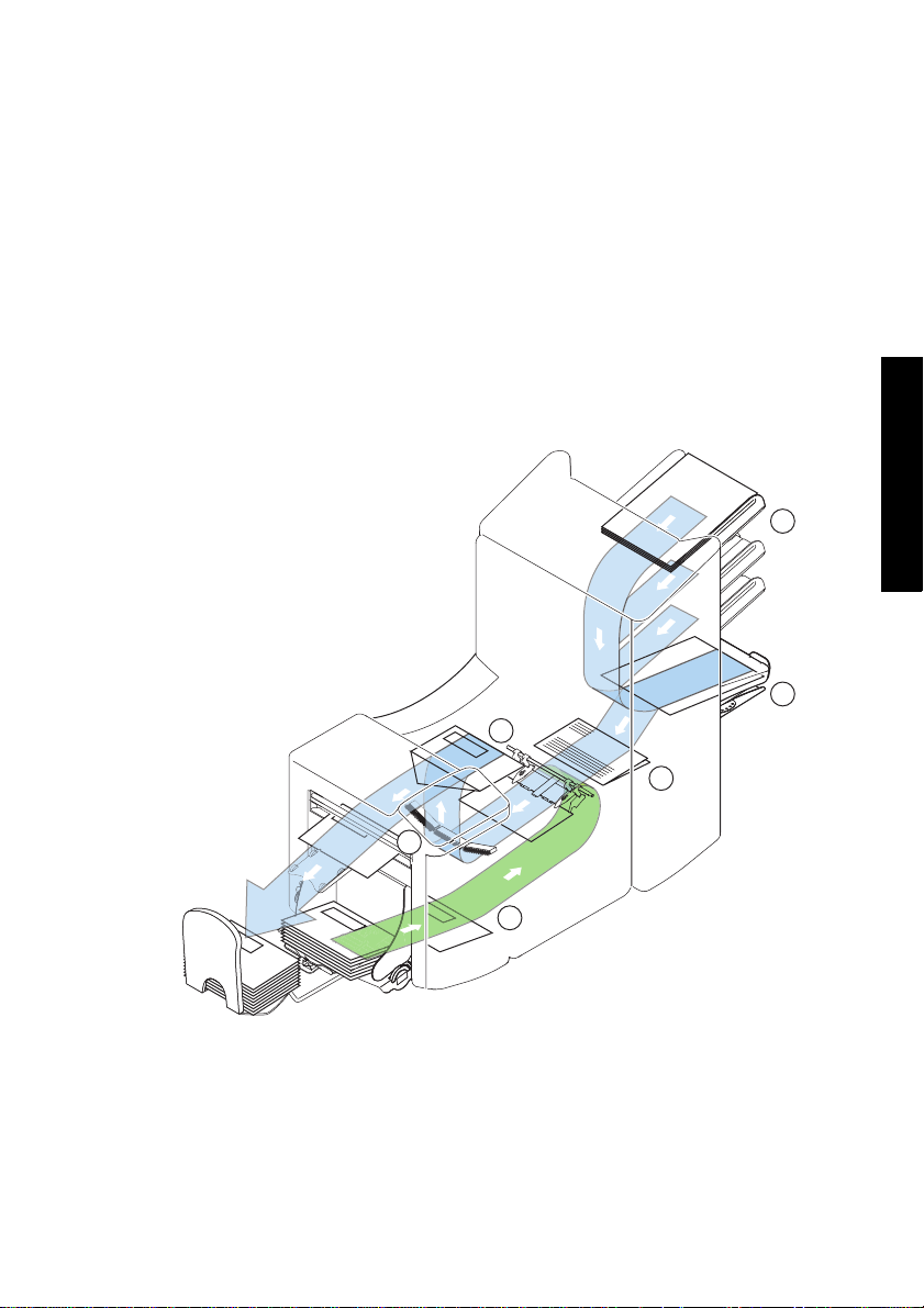
2. FUNCTIONAL DESCRIPTION
The system feeds, folds and inserts documents into envelopes and then seals and stacks
the envelopes. Automatic monitoring ensures the correct number of inserts per envelope.
The system is a sophisticated folding and inserting system which can process large
quantities of mail rapidly and easily. The system can be operated by means of a user
friendly interface.
The settings of the system (document type, envelope type and fold type) is recorded in
jobs. These jobs can be programmed by an authorized user.
The system is equipped with a variety of special features as programmable jobs, including
double feed control, hopper swap, multifee
2.1 Overview
The system consists of the following areas:
d, and daily mai
l.
1
ENGLISH
2
5
3
6
4
5
Page 8

2.1.1 Feeder (1)
The feeder is the feeding part of the system. There are two types of feeders available: the
automatic and the special feeder. The automatic feeder does not require any adjustments
for the separation. The feeder is equipped with double feed control. In this way the system
can detect faulty sets of documents. The feeder is equipped with hopper swap. This means
that two feeders can be linked as pairs. When the first feeder is empty, the system
switches to the other feeder. Meanwhile the other empty feeder can be refilled without
stopping the system. It’s also possible to feed multiple documents from one feeder. In this
way more documents can be fed from one station, for example an original and a copy of a
document.
The upper automatic feeder is equipped with a “daily mail” function for processing
documents or sets of documents which cannot be processed automatically (e.g. stapled).
2.1.2 Collating Area (2)
After feeding, the documents are gathered and aligned in the collating area.
2.1.3 Folder (3)
The folder unit folds the documents. The following fold types are possible (see
“Terminology” on page 54).
• No fold
• Single fold
• Letter fold
• Zig-zag fold
• Double parallel fold
2.1.4 Envelope Feeder (4)
The envelopes are picked up and transported to the insert position inside the system.
2.1.5 Inserter (5)
After folding the documents are transported to the inserter unit where the documents are
inserted into a waiting envelope. The inserter then seals the envelope.
6
Page 9
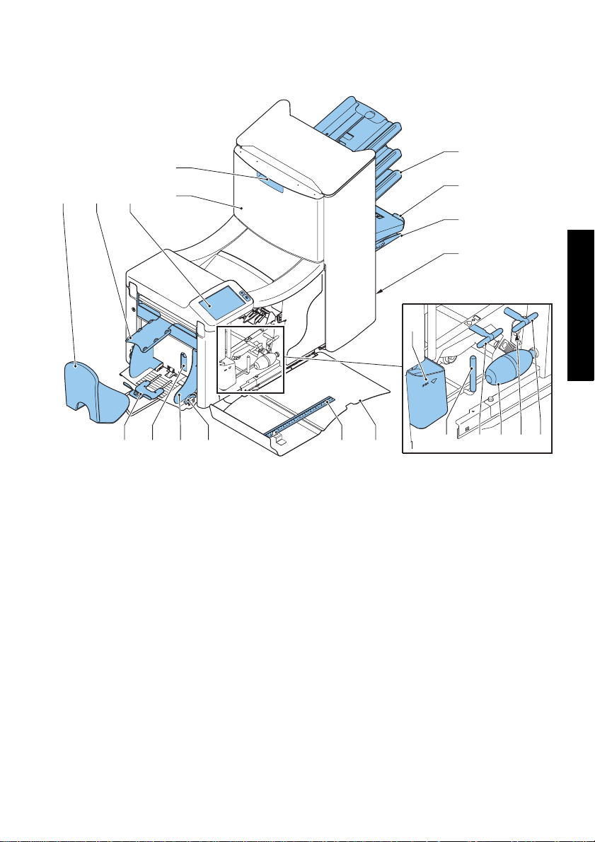
2.2 Operating Controls
E
A B C
D
F
G
H
I
N
Q OPRST
A catch tray K sensors
Benvelope slide L bellows
C control panel with touch screen M unlocking handle for rollers envelope
track
D upper unit N sealing liquid reservoir
E locking hand grip upper unit O side cover (opened)
F document feeder tray P ruler
G collator arm Q thumb wheel for side guide adjustment
H collating area R side guides envelope hopper
I power inlet, power switch,
RS232 connector / USB / modem
J handles for clearing jams T Envelope support bracket
S handle for separation adjustment
JM
ENGLISH
JKL
7
Page 10
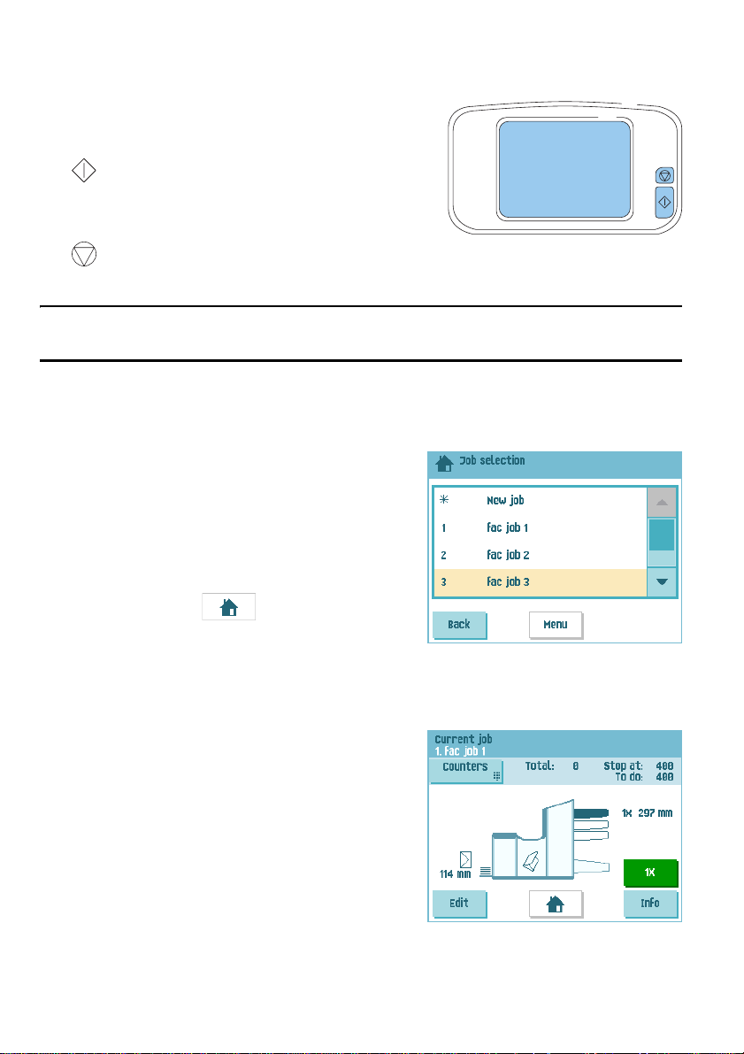
2.3 Control Panel
The system has a graphical touch screen.
There are two buttons next to the touch screen:
• : the start key
When the start key is pressed the system starts
processing
: the stop key
When the stop key is pressed, the system completes the current set and stops.
Caution
The touch screen is covered with a thin pressure-sensitive layer. To avoid permanent
damage of the touch screen, do not use sharp objects to press on the touch screen.
2.4 Software Description
2.4.1 Home
When you start up the system, the ‘home’ menu
appears. With the arrows you can scroll through the
jobs. If you want more information on a job, select
the job (see 2.4.2 ”Job Description” below).
If you just want to start without job definition, press
New job and select Automatic (see 3.8 ”Using an
Automatic Job” on page 18).
With the home button you get back to the
‘home’ menu.
The MENU button opens the main menu (see
2.4.3 ”Main Menu” on page 10).
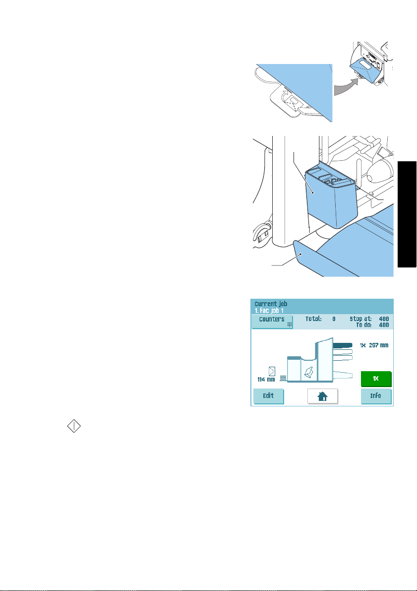
2.4.2 Job Description
If you want more information on a job, select the job
in the ‘home’ menu.
The ‘current job’ menu shows the following
information of the selected job:
• Job number and Job name
• Total: total number of envelopes that have been
processed using this job
• To do: number of envelopes to do. Only
indicated if a ‘stop at’ value is set.
8
Page 11
• Stop at: number of processed envelopes at which the system stops. You can set this
number with the Counters button. You can set it between 0 (switched off) and 9999.
The system will continue until the job counter reaches the stop counter value. The
system stops and can be restarted.The stop counter is switched off when it is set to
zero.
If you want to reset the daily job counter and the stop counter, press the Reset
counters button in the ‘counters’ menu.
Note
The counter settings are job related.
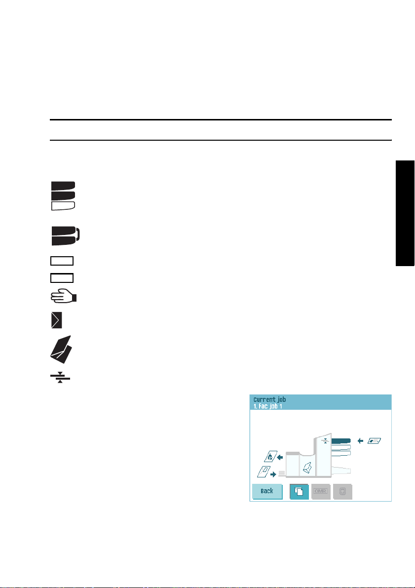
• A picture of the system with symbols for the selected features. The following symbols
can be used:
Shows the feeders selected to pick documents from (black is selected).
3X
Every selected feeder shows how many sheets will be fed from that
2X
feeder and the length of the sheets.
This sign indicates that the relevant feeders are linked. This means that
3X
when one feeder is empty, the system automatically starts picking
documents from the other feeder.
This sign indicates that for the selected feeder OMR or BCR is switched
OMR
BCR
on (optional).
This sign indicates that the relevant feeder is set for daily mail.
Gives information about the envelope size (ISO format or height in mm).
An envelope with a cross means that no envelopes are used.
Shows the type of fold, in this case letter fold.
ENGLISH
The sign indicates that for the relevant feeder the double feed detection
is switched on.
• Edit button: use this button to edit the job (see
“Edit a Job” on page 27).
• Info button: if you press the Info button, the
screen shows how to position the envelope and
documents in the feeders.
From this menu you can press a button to view
the reading settings.
.
9
Page 12
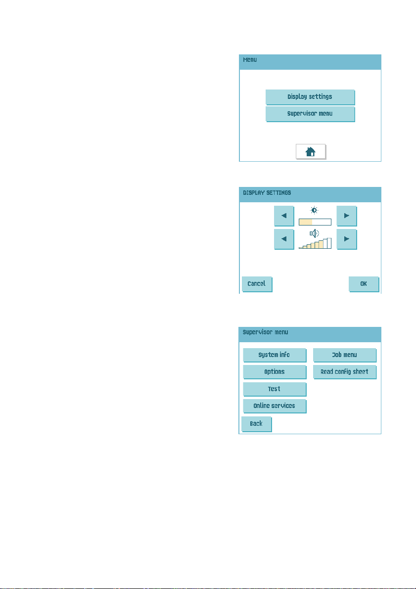
2.4.3 Main Menu
When you press the MENU button the main menu
appears. This menu allows you to change system
settings and define jobs. The screen shows the
following functions:
• Display settings: change touch screen and
volume settings (see “Display Menu” below)
• Supervisor menu: change syst
define jobs (see “Supervisor Menu” below),
only for authorized personnel
em settings and
2.4.4 Display Menu
When you press the Display settings button in the
main menu, the ‘display settings’ menu appears.
Use the arrow buttons to adjust the touch screen
contrast and the volume of acoustic signals. The
figure between the arrow buttons shows the level of
contrast or volume.
2.4.5 Supervisor Menu
When you press the Supervisor menu button in the
main menu, a login menu opens. Enter the PIN-code
2546 to access the ‘supervisor menu’.
If you enter 3 times a wrong pin code the touch screen shows the main menu again.
When you enter the correct pin code the ‘supervisor
menu’ appears. This menu enables you to check and
configure the system and maintain jobs.
The ‘supervisor menu’ shows the following functions:
• System info: shows system information, like:
- The software versions that are present in
the total system
- The flex certificate, used for reading
- The counter value since the last service visit
- The last error generated by the system
• Options: shows option information and system information:
-The chip ID
- The system ID
- The installed options
For installing new options, see 5.1 ”Activate an Option” on page 29.
10
Page 13
• Test: opens the ‘test menu’ (see 2.4.6 ”Test Menu,” below). Use this menu to
test the system.
• Online services: opens the ‘Online Services’ menu (option, see 5.3 ”Online Services”
on page 36). This menu enables to connect the system to a server and receive
messages.
• Job menu: opens the ‘job menu’. In this menu you can create, edit, copy or delete
jobs (see 2.4.7 ”Job Menu,” below).
• Read config sheet: reads Barcode Reading (BCR) settings from a BCR configuration
sheet.
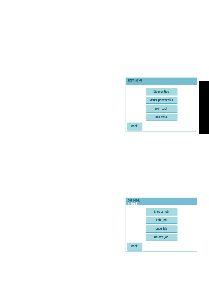
2.4.6 Test Menu
Open the ‘test menu’ from the ‘supervisor menu’.
Use this menu to check the system, reset all
photocells and execute a reading test. The ‘test
menu’ shows the following functions:
• Diagnostics: use this function to verify that all
motors, clutches and sensors are correctly
connected. This test briefly activates the
actuators and then measures the current to
determine the status of the actuators and
clutches.
Note
Remove all paper and close all covers before testing.
• Reset photocells: used for photocell calibration.
• OMR test: use this menu to test the reading head and the quality of the codes on the
sheets. Follow the directions on screen.
• BCR test: use this menu to test the reading head and the quality of the codes on the
sheets. Follow the directions on screen.
ENGLISH
2.4.7 Job Menu
When you press the Job menu button in the
‘supervisor menu’, the ‘job menu’ opens. This menu
enables you to create, edit, copy or delete jobs.
The ‘job menu’ shows the following functions:
• Create job (see 4.1 ”Create a Job” on page 20)
• Edit job (see 4.3 ”Edit a Job” on page 27)
• Copy job (see 4.4 ”Copy a Job” on page 28)
• Delete job (see 4.5 ”Delete a Job” on page 28)
11
Page 14
3. OPERATING INSTRUCTIONS
3.1 Installation
Warning
You can severely damage the system if it is connected to the incorrect power supply.
Before plugging in the system, check if the local voltage is the same as the voltage
mentioned on the type plate.
3.2 Preparation
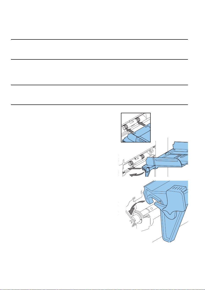
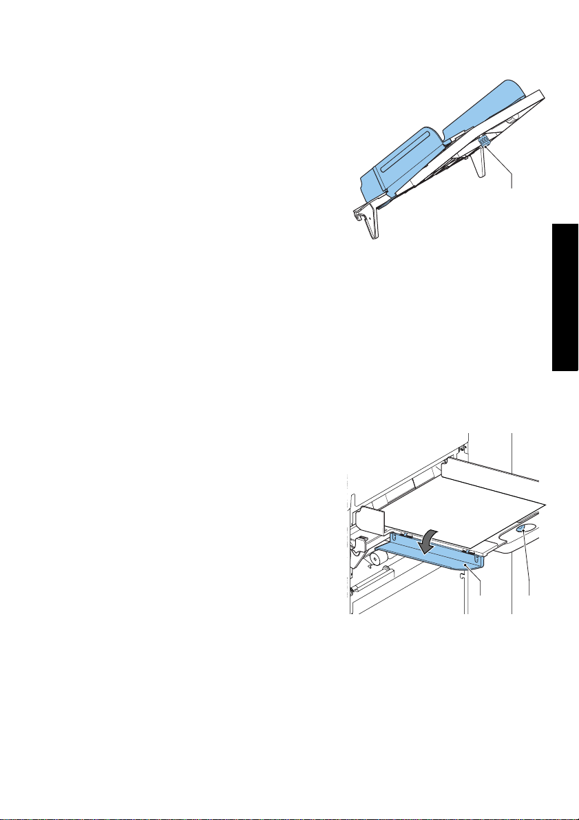
3.2.1 Document Feeder Trays
Note
The system can be delivered with a tray to manually adjust the separation (special
feeder). This tray fits in all positions, but the adjustment is only possible when fitted on
the lowest position (position one).
To place the document feeder trays in position:
1. Hold the tray slightly inclined as shown in the
figure.
2. Place the front end of the tray underneath the
two black rollers.
3. Move the tray upwards (lifting the black rollers),
until it is possible to ‘hook’ the tray into place.
4. Move the tray towards the system and move the
hooks over the mounting points (on both sides).
5. Let the tray rest on the system.
12
Page 15
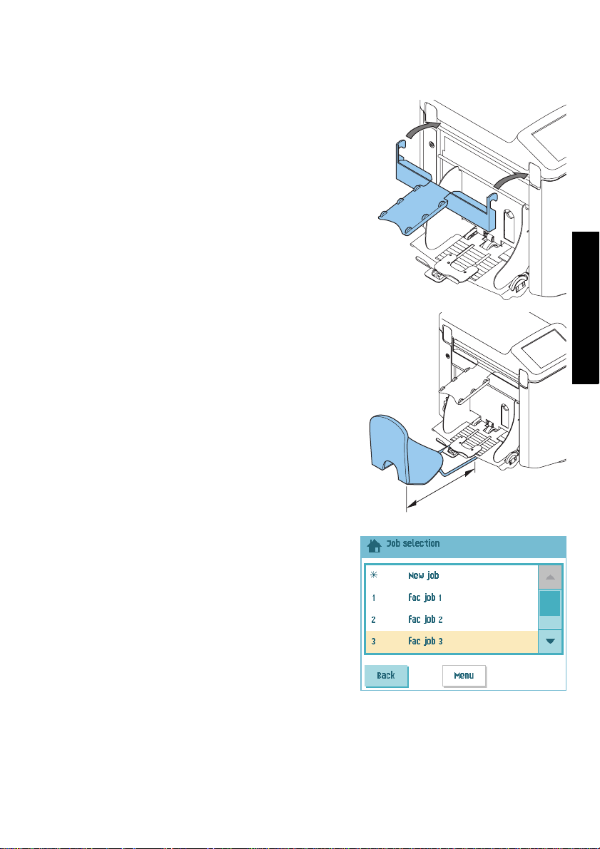
3.2.2 Slide and Envelope Catch Tray
To attach the slide and envelope catch tray:
1. Attach the slide as shown in the figure.
2. Position the envelope catch tray into the holes
underneath the envelope hopper as shown in the
figure.
The distance A should be approximately 1.5 x
the envelope height.
ENGLISH
3.3 Starting Up
To start up the system:
1. Connect the system to the mains power supply.
2. Use the power switch to switch the system on.
The power switch is located at the back of the
system.
The software will ask you to select the required
language.
3. Select the required language for the touch
screen.
The software will ask you if you want the “select
language option” to be displayed every time the
system is switched on.
4. Select either Yes or No.
5. Press the OK button.
The touch screen shows the home menu.
A
13
Page 16
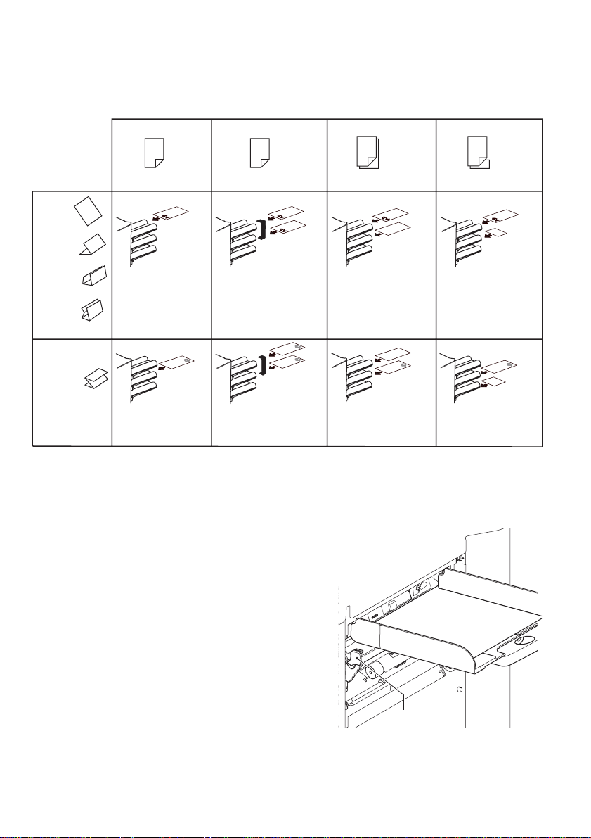
3.4 Loading Documents
3.4.1 Document Orientation
See also the job information on the touch screen.
feeder swap
Address carrier in upper
linked pair feeders.
Face up and leading.
Address carrier in lower
linked pair feeders.
Face down and trailing.
Address carrier in
upper feeder.
Face up and leading.
Address carrier in lower
feeder.
Face down and trailing.
no fold
single fold
letter fold
double
parallel fold
zig-zag fold
one document
Address carrier in
upper feeder.
Face up and leading.
Address carrier face
down and trailing.
3.4.2 Adjusting Side Guides
To adjust the side guides of the document feeder trays:
1. Remove the tray from the feeder as follows:
a Push handle
b Lift the tray upwards to unhook it and then
pull it out from the feeder.
A
downwards.
two documents
document + enclosure
Address carrier in upper
feeder.
Face up and leading.
Address carrier in upper
feeder.
Face down and trailing.
14
A
Page 17
2. Loosen the knob B half a turn.
3. Grab the side guides in the middle and push
them apart as far as possible.
4. Put a small stack of documents between the side
guides.
5. Grab the side gu
them towards the documents.
The space between the side guides and the
documents should be such that the documents
have just enough play to move freely.
6. Re-tighten knob
7. Remove the stack of documents.
8. Replace the document feeder tray (3.2.1 ”Document Feeder Trays” on page 12).
ides in the middle and push
B
.
B
3.4.3 Document Separation
‘Document separation’ means the adjustment that is required to separate the upper
document from the rest of the documents in the stack. This prevents picking up too many
documents from the stack at the same time.
The document separation for the automatic feeders is set automatically. There are no
manual adjustments needed.
Feeder 1 (the feeder in lowest position) can be a special feeder. You can manually adjust
the separation of special feeders as follows:
1. Remove feeder trays 2 and 3 (the upper trays).
B
2. Push the knob
3. Turn the left-hand side guide
4. Place a document on the feeder tray and slide it
about 60 mm (2.4 inch) into the system. Turn
the knob
set too narrow.
5. Push the document between the separation
rollers, which are behind the rubber paper
pullers.
6. Turn the knob
or counter clockwise to lower the resistance.
The separation is adjusted correctly when a slight resistance is felt on the document.
7. Pull the knob
8. Close the left-hand side guide.
forward until it clicks.
A
downwards.
B
counter clockwise if the separation is
B
clockwise to increase resistance
B
back again when ready.
A B
ENGLISH
15
Page 18
3.4.4 Filling the Document Feeder Tray
To fill the document feeder tray:
A
1. Turn the left-hand side guide
The feed rollers are lifted automatically.
2. Place a stack of documents between the side guides.
Feed the documents (depending on the type of documents and the type of fold) as
shown in 3.4.1 ”Document Orientation” on page 14.
3. Turn the left side guide upwards again.
downwards.
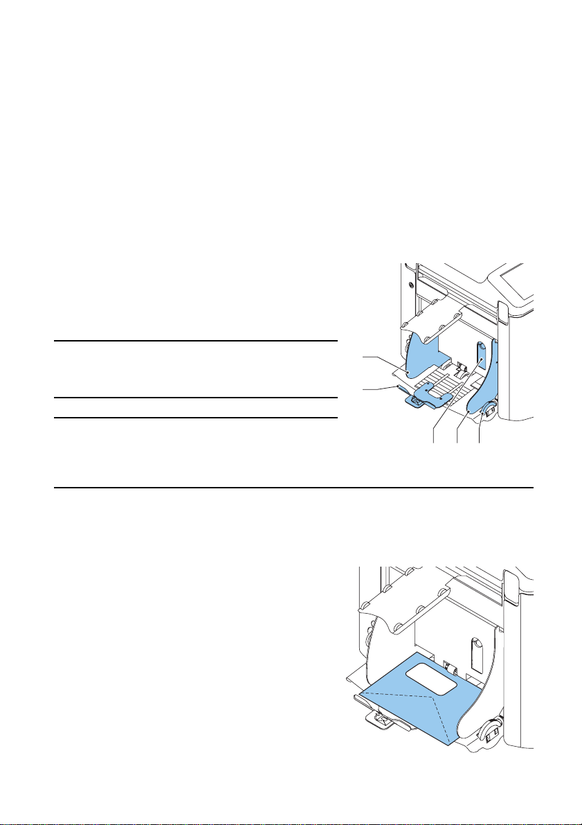
3.5 Loading Envelopes
To load the envelopes:
1. Adjust the side guides C with thumb wheel D so,
that the envelopes:
- Fit exactly between the side guides
- Can move freely
Note
If the distance between the side guides is too
large, the envelopes will twist sidewards, when
transported into the system.
Note
If you use the optional High Capacity Vertical
Stacker, also adjust the side guides of this
stacker (see “Adjusting the Side Guides” on
page 42).
2. Set the envelope separation as follows:
A
a Pull down small lever
b Insert one envelope horizontally up to the stoppers.
A
cReturn lever
3. Place the bottom envelope between the rollers
(flap down and trailing - bottom side of envelope
pointing to the system).
4. Loosen the stack of envelopes and place the
stack on top of the bottom envelope.
.
.
C
B
DCA
16
Page 19
5. Shift envelope support B in or out, so that the
top side of the envelope lies against the dotted
line on the support.
6. Turn envelope support B so the weight of the
envelopes is distributed evenly on both sides.
3.6 Filling the Sealing Liquid
Reservoir
When you want to seal envelopes, the sealing liquid
reservoir must be filled.
1. Open the front cover A.
2. Fill the reservoir B up to lip C with sealing liquid.
3. Close the front cover A.
Before you start the job, wait approximately 5
minutes for the brushes to moisten.
If the liquid reservoir is almost empty the
touchscreen shows a message to warn you that you
should refill the reservoir.
3.7 Run a Job
To run a job:
1. From the ‘home’ menu select a job.
If you press the OK button, the job information
appears (see “Job Description” on page 8).
2. Load envelopes as specified in the job. Press the
Info button for details.
3. Load the documents face up and leading, as
specified in the job. Press the Info button for
details.
Place the address carrier in the upper feeder.
4. Press the 1x button to start a test run or press
B
C
ENGLISH
A
the button to start the job.
If you press the 1x test button, the screen shows questions that help you to solve any
problems on mail set quality. If necessary this troubleshooting wizard helps you to:
- adjust envelope position (see 7.3.1 ”Insert Position” on page 49)
- adjust finger position (see 7.3.2 ”Envelope Insert Fingers” on page 49)
- adjust address position (see 7.3.3 ”Address Position” on page 49)
17
Page 20
3.8 Using AutoSet
If you do not want to define a job and just want to do some inserts, you can let the
system determine the job settings for you.
This ‘automatic’ job determines automatically its job settings by measuring the sizes of
documents and envelope. One sheet will be taken from all feeders that are loaded
on the maximum document
length of the envelope, the fold type is determined.
Note
AutoSet cannot be used together with linked feeders, multifeed, daily mail and
reading functionality.
The AutoSet is not possible in the no envelopes mode or with usage of
envelopes with open flap.
In AutoSet only the Double Feed Control (DFC) of the upper feeder is selected.
Note
Before starting an AutoSet job, be sure that no documents or envelopes are left in the
system.
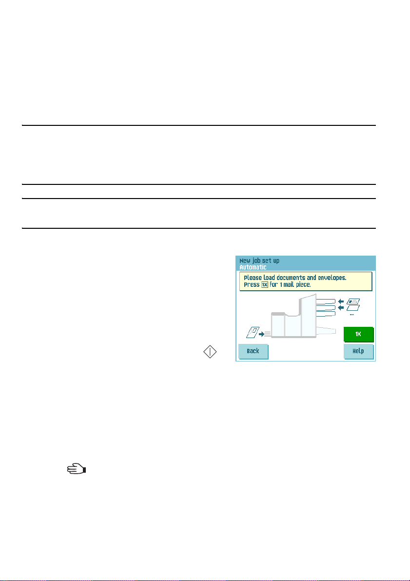
To start an AutoSet job:
1. From the ‘home’ menu, press the New job
button.
2. Press the Automatic button.
3. Load envelopes.
4. Load the documents face up and leading.
Place the address carrier in the upper feeder.
5. Press the 1x button to start a test run (see
length (which is also the length of the document set) and the
. Based
3.7 ”Run a Job” on page 17) or press the
button to start the job.
6. If you press the Save button you can copy this job to a job number.
3.9 Daily Mail
To process documents or sets of documents, which can not be processed automatically
(e.g. stapled documents), the top feeder is equipped with a daily mail switch.
To use the Daily Mail function:
1. Select a job where the daily mail function is selected. You can recognize the daily mail
by the icon in the job information menus.
18
Page 21

2. Turn down the left side guide A of the upper
tray.
Now you can see the Daily Mail handle B
().
3. Move the handle to enable the Daily Mail
function.
4. Place the document or document set in the
feeder (see “Filling the Document Feeder Tray”
on page 16) and turn side guide A upwards.
B
5. Press the button to start the job.
The document or document set will be folded
and inserted into the envelope as described in the selected job.
6. Place the next document or document set in the feeder. The system will keep running
to process the inserted document or document set.
7. When finished with Daily Mail, press the button to stop the job.
8. Set the Daily Mail handle B to the ‘AUTO’ position to disable the Daily Mail and enable
the automatic document separation.
A
3.10 Stopping the system
To stop the system press the button. The system completes and inserts the current
set and stops. This results in a cleared system which is ready to process a new job.
ENGLISH
19
Page 22

4. JOB PROGRAMMING
4.1 Create a Job
To c re at e a n ew j ob :
1. From the ‘home’ menu, press the New job button.
2. Press Manual to create a new job.
For Automatic, see “Using AutoSet” on page 18.
3. Enter the pin code 2546.
4. Press Wizard to create a new job with the job
creation wizard or press Advanced (experienced
users only).
If you use the job creation wizard, follow the
steps on screen. The system stores the new job
under the lowest free job number.
You can manually select a free job number to
save the new job. The screen will show the
lowest free job number.
If you use the advanced way of job
programming, continue as follows:
5. Press OK to confirm the selected free job number.
Note
A new selected job number starts with default settings.
The ‘job settings’ menu opens. The meaning of all buttons and settings is explained in
4.2 ”Job Settings” on page 21.
6. Press Save to save the job with the entered settings under the specified job number
and name.
To n am e a j o b, s e e 4 .2. 6 ”Job Name” on page 26.
7. Press the 1x button to verify that the insert position and address position are correct
(see 7.3.1 ”Insert Position” on page 49 and “Address Position” on page 49).
20
Page 23

4.2 Job Settings
From the “job settings” menu the following settings
are available:
Envelope settings (see 4.2.1 ”Envelope
Settings," below)
Document settings (see 4.2.2 ”Document
Settings” on page 22)
Fold settings (see 4.2.3 ”Fold Settings” on
page 24)
Reading settings (if installed) (see
4.2.4 ”Reading Settings (Option)” on page
25)
Double feed control settings (see
4.2.5 ”Double Feed Control Settings” on
page 26)
Job name settings (see 4.2.6 ”Job Name” on
page 26)
Mailing/Franking settings (if installed) (see
4.2.7 ”Mailing/Franking Settings (Option)”
on page 27)
Mail Piece Production Control (MPPC)
settings (if installed)
See the appendix operator manual Mail
Piece Production Control
If you want to view the job details of the current job, press the button. If you want to
run a test set or test envelope, you can use the green buttons in this menu.
ENGLISH
4.2.1 Envelope Settings
In the ‘envelope settings’ menu you can define the
envelope properties and switch the sealing on and
off.
In the top of the screen, three selection buttons are
displayed, from which one can be selected. The
selected settings button will be highlighted.
• Press to select an envelope with closed
flap. This means that the envelopes are fed with
closed flap. Use the upper button to enter
the applicable dimensions.
It is also possible to select ISO standard envelopes or dimensions in inches (depends
on the installation settings).
The envelope height can be set between 90 mm (3.5 inch) and 162 mm (6.38 inch).
21
Page 24

Use the button to switch automatic envelope sealing on, off or use reading (in
case of a job with reading settings, see ”Sealing Control” on page 34).
• Press to select an envelope with open flap.
This means that envelopes are fed with open
flap. Use the upper button to enter the
applicable dimensions.
The envelope height can be set between 90 mm
(3.5 inch) and 162 mm (6.38 inch).
It is also possible to select ISO standard
envelopes or dimensions in inches (depends on
the installation settings).
Use the second button to enter the flap height.
The flap height can be set between 32 mm and the envelope height minus 32 mm
(1.26 inch).
Use the button to switch automatic envelope sealing on or off.
• Press to define a job without inserting the documents in envelopes (no envelope
mode). This can be useful for jobs, where documents only have to be sorted and/or
folded.
4.2.2 Document Settings
In the ‘document settings’ menu you define the
document formats and the number of documents
that must be picked from the different feeders.
• Press to set the number of sheets for the
different feeders.
- Press to select a feeder. The selected
feeder is highlighted.
- Press the arrows to change the number of
sheets that must be picked from the
highlighted feeder. When the number of documents is 0, the selected feeder will
be deselected.
Note
When a feeder is set to daily mail the number o f documents is always 1 and can not be set
in this menu.
22
Page 25

Note
The maximum number of sheets in a set is 25. When folding is used the maximum set
thickness is 8 sheets in letter fold and 10 sheets (80 gr./m2) in single fold.
• Press to enter the document height. The height or the ISO format of the
document will be displayed next to the relevant feeder.
- Press to select a feeder. The selected feeder is highlighted.
- Press to show a numeric keypad to enter the exact dimension of the
document.
Dimensions can be entered in mm, inches or as standard ISO paper dimensions
(depending on installation settings). The system will not allow entering
dimensions out of technical ranges. The document size can be set between 90
mm (3.54 inch) and 356 mm (14 inch).
The default document size setting of a new job is 297 mm (11.7 inch).
• Press to link two feeders. This function enables to fill two adjacent feeders with
the same documents. When the first feeder is empty, the system automatically swaps
to the other feeder.
- Press to select two adjacent feeders. The selected feeders will be
highlighted.
- Press to link two highlighted feeders.
ENGLISH
The will be displayed between the selected feeders.
Note
When linking two feeders, the program will automatically apply the number and format of
the documents of the lowest feeder to the other feeder.
Note
When a feeder is selected for reading, the feeder below can not be linked to this reading
feeder. The reading feeder can be linked to a feeder above when it is not selected for
selective feeding.
• Press to enter the setting of the daily mail function.
This function enables to process documents or sets of documents, which can not be
processed automatically (see 3.9 ”Daily Mail” on page 18). The upper feeder is
automatically selected.
23
Page 26

- Press to enable the daily mail function. The icon appears behind the
upper feeder. If you press again the daily mail function will be disabled.
Note
The daily mail function is only available when reading is not activated. When daily mail is
set, the links to the daily mail feeder will be deselected automatically.
Note
When the daily mail function is selected Double Feed Control is not available.
4.2.3 Fold Settings
In the ‘fold settings’ menu you can adjust the folding dimensions and folding type.
Select the fold type. The following choices are
available:
No fold (no settings required)
Single fold
Letter fold
Double parallel fold
Zig-zag fold
Except when no fold is required, the touch screen shows a simple diagram of the
document with the fold positions. To change the fold positions press next to a fold.
Enter the required position of the relevant fold.
Fold type Minimum position Maximum position
Single fold 75 mm (2.95”) Longest document length
minus 25 mm (0.98”)
Letter fold First fold 75 mm (2.95”) Longest document length
Second fold Position first fold
plus 26 mm (1.02”)
Zig-zag fold First fold 75 mm (2.95”) Longest document length
Double parallel
fold
Second fold Position first fold
First fold 75 mm (2.95”) Longest document length
Second fold Position first fold
plus 25 mm (0.98”)
plus 25 mm (0.98”)
minus 50 mm (1.97”)
Longest document length
minus 25 mm (0.98”)
minus 100 mm (3.94”)
Longest document length
minus 75 mm (2.95”)
minus 51 mm (2.0”)
Longest document length
minus 25 mm (0.98”)
24
Page 27

Note
The touch screen will indicate when entered positions are out of range.
4.2.4 Reading Settings (Option)
For a full function description of reading, see
5.2 ”Reading” on page 29. In the ‘reading settings’
menu it is possible to enable or disable the Optical
Mark Recognition (OMR) or Barcode Reading (BCR)
function and to adjust the basic settings.
The first ‘reading settings’ menu covers the following
settings:
• Code type: default is the setting ‘none’: reading
is disabled.
Change the setting with the button. The
following codes are possible:
- 1-track OMR codes
- BCR for reading barcodes
- Flex 1-9 for reading customer specific codes (only if flex dongle is installed)
• Read from feeder: press the button to select a feeder to activate reading on.
By pressing the button the next reading
settings menu appears. This menu covers the
following settings:
ENGLISH
• 1st mark from top: press to set the
position of the first optical mark, measured
from top of the sheet. The value can be varied
between 15 mm (0.6 inch) and 277 mm
(10.9 inch). If you selected BCR, a second
keypad is available to enter the length of the
code.
• Max. sheets: use the arrow buttons to select the maximum amount of sheets in the
set of documents.
25
Page 28

Note
The maximum number of sheets in a set is 25. When the number of sheets exceeds 8 or
10, depending on the fold, the document can not be folded anymore. In this case, the
maximum length of sheets is 148 mm for a C5/6 envelope. Also make sure that the fold is
set to No fold.
Ignoring this will certainly lead to stoppages.
When the maximum number of sheets exceeds the programmed maximum number of
sheets in a set, the system stops and error INS-RE-14 will be displayed. After removing
the set and pressing the Reset button, the system will start and repeat the process until
an insert or divert mark is encountered, error INS-RE-15 (final set part) will be displayed.
4.2.5 Double Feed Control Settings
In the ‘DFC settings’ menu you can set Double Feed
Control (DFC) for the different feeders on or off.
To set the DFC for the different feeders:
1. Press the button to select a feeder.
2. Press the button to switch the DFC on or
off. When switched on, the icon is displayed.
When a job is started, the first document taken per
feeder is used for a reference measurement. When a
document is exceeding that reference thickness an error will be displayed.
Note
When Daily mail is selected, the DFC will be switched off automatically.
4.2.6 Job Name
It is possible to store the job with a meaningful job
name, to easily recognize the job. This name is
displayed at job selection. Enter a job name with the
alpha-numeric keypad.
• Use the button to clear a character left of
the cursor position (backspace).
• Use the button to clear all entered
characters and start again.
26
Page 29

4.2.7 Mailing/Franking Settings (Option1)
If this system is connected to a mailing/franking
system, this option allows you to select the franking
mode. The ‘franking settings’ menu has the following
options:
• Franking: use the button to switch
between
- Yes (franking on)
- Pass through (franking off)
• Value defined
between:
- Franking machine: the mailing (franking) system will print/frank the envelopes
according to the local mailing (franking) system settings. To link a mailing
(franking) job to the inserter job, use the arrow buttons to select a job. If no link
is required, select ‘Current job’.
- Inserter: the mailing (franking) system will
print/frank the envelopes according to the
size data communicated by the inserter.
If you press the Next button a menu
appears via which the weight of single
documents and envelopes and the envelope
width can be entered. Use the Weight
settings and Envelope width buttons to
enter these data.
To link a mailing (franking) job to the
inserter job, use the arrow buttons to select
a job. If no link is required, select ‘Current job’.
Refer to the appendix for an extensive description of the mailing (franking) option.
by: use the button to switch
4.3 Edit a Job
To edit an existing job:
1. From the ‘home’ menu, select a job you want to
edit.
2. Press the Edit button.
3. Enter the pin code 2546.
The ‘job settings’ menu opens. Refer to 4.2 ”Job
Settings” on page 21 for the meaning of all
buttons and settings.
ENGLISH
1. Ask your supplier if this option is available for your mailing/franking system.
27
Page 30

4. Press Save to save the job with the entered settings under the specified job number
and name.
To n am e a j o b, s e e 4 .2. 6 ”Job Name” on page 26.
5. Press the 1x button to verify that the insert position and address position are correct
(see 7.3.1 ”Insert Position” on page 49 and “Address Position” on page 49).
4.4 Copy a Job
To copy existing job settings to a new job:
1. Press the Supervisor menu button from the
main menu.
2. Enter the pin code 2546.
3. Press the Job menu button.
The ‘job menu’ opens.
4. Press the Copy job button.
The ‘copy job’ menu appears.
5. Press the arrows if you want to select another
job number to copy from or to copy to.
Note
You can only copy job settings to new jobs.
6. Press for details of the job to copy from.
7. Press OK to copy the job settings.
If all jobs are programmed the touch screen shows “No more free jobs”.
It is possible to copy an Automatic job into a job. Before an Automatic job can be copied,
it has to be defined successfully (see 3.8 ”Using an Automatic Job") on page
18).
4.5 Delete a Job
To delete an existing job:
1. Press the Supervisor menu button from the
main menu.
2. Enter the pin code 2546.
3. Press the Job menu button.
The ‘job menu’ opens.
4. Press the Delete job button.
The ‘delete job’ menu appears.
5. Select a job number and press OK. The job will
be deleted without a warning.
28
Page 31

5. OPTIONS
5.1 Activate an Option
To activate a new option:
1. From the ‘supervisor menu’ choose Options.
Software options are enabled with license codes. These license codes, together with
the identification number of the system enable the relevant options. The enabled and
available software options are displayed in this menu. Contact your dealer for
information about these license codes.
2. Press Add to activate other software options.
3. Enter the license key code that you received
from the supplier to activate the relevant option
on this system.
Use the arrow keys to navigate through the
entered characters.
4. Press OK to confirm the license key and to
return to the ‘options’ menu.
5. Switch the system off and on.
5.2 Reading
5.2.1 Introduction
The folding and inserting system can be equipped with reading. This allows the system to
read special codes that have been printed on the documents. These codes contain
information about the processing of the sheets. Two types of codes are available:
• OMR: Optical Mark Recognition
• BCR: Bar Code Recognition
The sheets with the printed code are placed in the reading feeder. Depending on the
programmed
In case of a zig-zag fold, the address has to be printed on the last page of the set. With
the other fold types, the first sheet of a set always contains the address. A full length code
is printed on every sheet of a set. The code must appear in the same location on every
page regardless of the actual code length.
The code on the last sheet of the set contains the insert instruction. The other sheets
carry the accumulate instruction. If a parity check is used with OMR, this is checked on
each sheet. If the “page n of m” code is used with BCR, the set will be inserted when n
equals m.
Both reading options can be enabled with a special license code (refer to “Activate an
Option” at top of this page).
code, the other feeders can be used as selective feeders to add enclosures.
ENGLISH
29
Page 32

5.2.2 Adjust Reading Head Position
The horizontal position of the reading head must be adjusted to the same position of the
printed marks on the documents.
To adjust the reading head, proceed as follows:
1. Fold a document with reading code on the first
mark.
2. Open the upper unit (see page 7).
3. Hold the document in the middle against the
ruler.
4. Shift the reading head A so it is positioned
exactly above the middle of the reading marks.
5. Divide the paper guides B along the width of the
document.
Note
When the reading head is adjusted it is possible
that paper guides have to be removed and
placed on the other side of the reading head.
A B
30
Page 33

5.2.3 Document Orientation
Switch on the reading function and set the position of the reading marks as described in
“Reading Settings (Option)” on page 25.
Document orientation:
Fold type
no fold
single fold
Type of documents
first page
Loading positions
1
2
3
letter fold
Double
parallel fold
zig-zag fold
address
last page
(duplex printed)
start
reading
start
reading
stop
reading
stop
reading
address
Address carrier, face up and leading.
Address carrier, face down and trailing.
3
2
1
5.2.4 Reading Codes
Printing Quality
• Marks should be printed in black.
• Marks on the same sheet must have equal intensity.
• Marks must be printed on the same position on every sheet.
• For matrix printers near letter quality (NLQ) printed characters are preferred to obtain
maximum blackness (double strike).
• Be aware of background “noise”. Color changes on the form, background design, a
logo or copy on the opposite side of the sheet that will bleed through can be read by
the reading head, causing disturbances of the reading function.
• The ribbon or toner quality must be checked before printing.
ENGLISH
31
Page 34

OMR Code Specification
The following specifications apply to OMR codes:
Leading
Reading direction
>8.5 mm 2.54 - 6.36 mm >8.5 mm
>30 mm >15 mm
>4.2 mm >4.2 mm
>7 mm
Trailing
>7 mm
Minimal distance from top of sheet to first mark 15 mm (0.59 inch)
Minimal distance from bottom of sheet to last mark 30 mm (1.18 inch)
Minimal distance from side edges of sheet to marks 7 mm (0.28 inch)
Minimal free space above and below the marks 8.5 mm (0.33 inch)
Minimal free space on both sides of the marks 4.2 mm (0.17 inch)
Minimum space between OMR marks 2.54 mm (0.10 inch)
Maximum space between OMR marks 6.35 mm (0.25 inch)
Minimum width of the marks 6.3 mm (0.24 inch)
Minimum line thickness of a mark 0.2 mm (0.008 inch)
• Default the first mark from the top is set to 100 mm (3.9 inch). This parameter is set
in the ‘Reading settings’ menu of the ‘Job settings’ menu.
• The code m ust ap pea r in th e same location and ha ve a cons istent nu mber o f marks on
every page.
>6.3 mm
32
Page 35

BCR Code Specification
Minimal distance from top of sheet to first bar 15 mm (0.59 inch)
Minimal distance from bottom of sheet to last bar 30 mm (1.18 inch)
Minimal distance from side edges of sheet to barcode 7 mm (0.28 inch)
Minimal free space above and below the barcodes 8.5 mm (0.33 inch)
Minimal free space on both sides of the barcodes 4.2 mm (0.17 inch)
Minimum height of a bar 9 mm (0.35 inch)
Minimum line thickness of a bar 0.25 mm (0.01 inch)
The length of the code is a job setting. The code must appear in the same location on
every page.
Minimum Code/Basic Commands
In case of OMR the minimum code is one mark in
one line (insert). However for reliability it is advised
to use at least 2 marks. The first line is the start
mark. A mark printed on the second line means
insert. No mark on the second line means
accumulate.
Note
In some cases, on request of the customer, the reading of the basic commands can be
reversed by the service organization. This means that no mark is interpreted as an insert
command and that for the accumulate command a mark has to be printed.
Start mark
Insert/accumulate
ENGLISH
In case of BCR the minimum codes are also for
accumulate and insert.
33
Page 36

Additional Codes
When it is required to control more functions in the
inserter system, additional codes are available.
The following additional functions are possible via
software options:
•Divert
•Stop
• Selective feed from station 1
• Selective feed from station 2
• Selective feed from station 3
• Sealing control
• Sequence check 4, 2 and 1 (respectively with 1,
2 or 3 marks, only OMR)
• Parity check mark (even, only OMR)
• Safety mark (only OMR)
General remarks:
• In case of OMR the marks must always be used
in the above sequence.
• If a function is suppressed the following function
will move upwards one line.
• The chosen code must always be used on all
material processed by reading.
• The mark definition is a service setting (OMR).
• Other functions are possible via special codes
(Flex codes)
Start mark
Insert/accumulate
Divert mark
Stop mark
Selective feed 1
Selective feed 2
Selective feed 3
Sealing control
Sequence check 4
Sequence check 2
Sequence check 1
Parity (even parity)
Safety mark
Divert
The system stops, manually remove the set from the
collator. Reset and start again.
Stop
The system stops, manually remove the set from the collator. Reset and start again.
Selective Feed
The system will selectively feed an enclosure when commanded so.
Sealing Control
When the ‘sealing control’ mark is printed, sets will not be sealed. When no ‘sealing
control’ mark is printed, sets will be sealed.
34
Page 37

Sequence Check (only OMR)
Sheets in a stack can accidentally get out of
sequence or can be missing. This can be
detected by the system when the sequence
function is used. Each sheet has a number
that forms part of the reading code.
These are the available possibilities:
• 1 mark: pages are numbered 1-2-1-2-1etc.
• 2 marks: pages are numbered 1-2-3-4-12-3-4-1-2-etc. (see figure)
• 3 marks: pages are numbered 1-2-3-4-56-7-8-1-2-3-etc.
The table shows examples of sequence check.
Marks on the sheets: sheet count
Sequence check 4 (3 marks used)
Sequence check 2 (2 marks used)
Sequence check 1
(1 mark used)
#1
1 2 3 4 5 6 7 8
--------
--------
- - - - - - - -
#2
1
A
2
3
A
B
4
5
B
B
6
C
C
#3
#4
#1
#2
#3
- = Mark printed, - = No mark printed
Note
If you use sequence control and the system stopped, you can reset the sequence counter
7
ENGLISH
as follows: press the (stop) button and press the Yes button to confirm.
Parity Mark (only OMR)
By adding a parity mark the reading code can be checked. When the OMR advanced
package is used the sum of the marks has to be even.
Safety Mark (only OMR)
The safety mark is used as an extra security. With
skewed paper the reading head can miss part of the
reading code. In these situations the safety mark is
not read, and the system will give an error.
The safety mark also indicates the end of the
reading code.
This mark must always be present on the document
if it has been activated as an OMR code.
Normal paper flow Skewed paper flow
Start mark Start mark
Safety mark Safety mark
reading direction reading direction
35
Page 38

Page n of m (only BCR)
BCR uses the code ‘page n of m’ to complete a set. If n is less than m, the sheets are
accumulated. If n = m, this is the last sheet of the set and the set will be inserted.
Example of OMR Code
In the figure the legend for the following example is
shown. In this example feeder station 3 is the
reading feeder. The feeder stations 1 and 2 are
selected for selective feeding.
In this example, a set of 8 sheets with two selective
feeds (station 2 and 1) and three sequence check
marks is shown.
• The first position is used for the start mark
which must be printed on every sheet.
• The second mark position is used for the insert/
accumulate command. The mark is printed on
the last sheet of the set (inserting is required).
• Position 3 and 4 are reserved for selective
feeding from station 2 and 1. Print a mark on
position 3 when a selective feed from station 2
is required. Print a mark on position 4 when a
selective feed from station 1 is required. The
marks are printed on the last sheet of the set.
• Position 5, 6 and 7 are used for the sequence check marks. The meaning of the
sequence check marks is explained in section ”Sequence Check (only OMR)” on page
35.
mark printed
no mark printed
accumalate
insert
or
no selective feed
wanted, mark not
printed
selective feed
wanted, mark
printed
Sheet 1Sheet 2 Sheet 3 Sheet 4 Sheet 5 Sheet 6 Sheet 7 Sheet 8
reading feeder 3
selective feeder 2
selective feeder 1
5.3 Online Services
The folding and inserting system can be equipped with Online Services. This option
enables the system to connect to a central server. During the connection data is
downloaded to and uploaded from the system. The system always initiates the
connection, it is not possible to make a connection from outside to the system. Ask your
supplier if this option is available.
5.3.1 Start-Up Online Services
To s ta rt- u p O n line Services:
1. From the ‘supervisor menu’ choose Online
services.
The ‘Online Services’ menu shows the following
functions:
• Connection: opens the ‘connection’ menu to
create a connection to a central server and to
view the connection history (see ”Connection”
on page 37).
36
Page 39

• Messages: opens the ‘messages’ menu to view received messages (see ”Messages”
on page 37).
• Configuration: opens the ‘configuration’ menus to change Online Services settings
(see ”Configur ation Menu” on page 38).
Connection
The system makes a connection on fixed times. It is
possible that you manually connect the system to
the server. To connect to the server:
1. Press Connection in the ‘Online Services’
menu.
The touch screen shows the ‘connection’ menu.
2. Press Connect to manually connect the system
to the OLS server.
You can view the status of the connection on the
screen. The text on the button changes to Disconnect.
Press Disconnect to terminate connection with the server.
The ‘connection’ menu shows the following functions:
• History: opens the ‘history’ menu to view the connection history (see ”History” on
page 37).
• New messages: this button appears when the system received new messages and
opens the ‘messages’ menu (see ”Messages” on page 37).
History
The ‘history’ menu shows previous connections of
the system to the server.
1. Press the arrows to select a previous
connection.
ENGLISH
2. Press to view details on selected previous
connection.
Messages
After pressing Messages in the ‘Online Services’
menu the touch screen will show messages received
from the server. A message has content like a new
job or new software.
1. Press the arrows to select a message.
2. Press for more information over a selected
message.
In case a new job or new software can be installed
the Continue button appears.
37
Page 40

To install a new job or new software:
1. Press Continue.
The ‘new job available’ menu or ‘new software’ menu appears. Press for more
information on the new job or new software.
2. Press Install to install the new job or new software or press Reject to reject it.
After pressing Install a confirmation menu opens:
• In case of a new job press the arrows to select a free job number (see 4.1 ”Create a
Job” on page 20).
Press OK to confirm the selected job number or press Cancel to return to the ‘new
job available’ menu.
• In case of new software press OK to confirm the installation or Cancel to return to
the ‘new software’ menu.
After confirming the installation of the new job or new software the ‘message’ menu
appears.
Configuration Menu
After pressing Configuration in the ‘Online
Services’ menu the ‘configuration’ menu opens. Use
this menu to modify the OLS settings.
The menu consists of two submenus containing the
following functions:
• Telephone number of server: contact your
supplier for the telephone number of the OLS
server.
To change the number:
aPress .
b Enter the correct number using the numeric keypad.
cPress OK to confirm the new number.
• Prefix: use this function in case you need to dial a certain number or string to access
an outside line.
aPress .
b Enter the correct prefix using the numeric keypad.
cPress OK to confirm the new number.
• Country: use the arrows to select a country from where you are dialing.
• Date and time: enter the current date and time.
aPress .
b Enter the correct date and time using the numeric keypad.
cPress OK to confirm the new date and time.
38
Page 41

• Dial tone detection on / off
This setting is required if no dial tone is heard during establishing a connection. The
default value is on. This setting is relevant to some PABX telephone switch systems.
Press to switch the dial tone detection on or off.
• Volume of modem: set the modem volume.
a Press to change the volume of the speaker.
Do not set the volume to zero as the sound of the modem is helpful during
remote assistance.
Press OK to confirm modified settings.
5.4 Production Feeder (MF-2)
5.4.1 Function
The Production Feeder is a feeder that can be loaded with a high number of documents.
This feeder is intended to be used for Business Reply Envelopes (BRE), but also ‘standard’
documents up to 156 mm (6.1") length can be processed with it.
5.4.2 Preparations
The Production Feeder should be installed at the
position of feeder no. 1.
It can be placed into position in the same way as the
other document feeders.
Proceed as follows:
1. Lift the paper feed rollers with the front edge of
the Production Feeder
2. Move the Production Feeder forward until it hooks
behind th
3. Connect the connector A to the socket B.
The Production Feeder is auto-detected by the system
when the system is switched on. This makes it easy
to switch over from the standard document feeder tray to the Production Feeder and vice
versa.
e frame axle.
.
A B
ENGLISH
Note
To allow easier hooking on of the Production Feeder it is advised to put the feeding plate in the
rear position (see 5.4.4 ”Document Separation” on page 40).
To use the Production Feeder it is not necessary to (re-)program the jobs
.
39
Page 42

5.4.3 Adjust Side Guides
Adjust the side guides:
1. Take a stack of documents/B REs and place them
in the feeder tray.
BREs with flap down and leading (top side
pointing to system).
2. Adjust the side guides by turning the thumb
wheel G so the documents/BREs just fit and can
move without resistance.
Too much play causes skewing.
G H I J
5.4.4 Document Separation
When the Production Feeder is used as an automatic
separation feeder, the separation is set
automatically.
The Production Feeder
position with a manually adjusted separation.
To adjust, proceed as follows:
1. Remove feeders 2 and 3.
Note
The lowest feeder is feeder 1.
can also be used on a feeder
C D F
2. Squeeze the two blue handles C and D and shift
the feeding plate F as far as possible to the front.
3. Push knob E forward until it clicks.
4. Place a document/BRE on the feeder tray and slide it in the system till the leading
edge is not visible anymore. Turn knob
narrow.
5. Push the document/BRE between the rollers.
E
6. Turn knob
set too narrow.
The separation is adjusted correctly when a slight resistance is felt on the document/
BRE.
7. Pull knob E back when ready.
8. Remount feeders 2 and 3.
clockwise to get more resistance and counterclockwise if the separation is
E
counterclockwise if the separation is set too
E
5.4.5 Feeding Documents
To feed documents:
1. Squeeze the two blue handles C and D.
2. Shift the feeding plate F to the rear position.
40
Page 43

3. Loosen the stack of documents and place them in the feeder.
BREs with flap down and leading (top side pointing to system).
The feeding plate assembly will be shifted up automatically (when the system starts
processing) until documents/BREs are underneath the rubber paper pullers.
Note
When filling the Production Feeder, be sure that the document/BREs are position
in relation to the feed plate to ensure correct feeding.
ed parallel
5.5 High Capacity Feeder
This option can only be installed from factory. The High Capacity Feeder has a capacity for
up to 725 sheets. The normal document feeder tray has a capacity of 325 sheets.
5.5.1 Installation of Feeder Tray
To install the feeder tray of the High Capacity
Feeder:
1. Pull down lever A.
2. Hook in the feeder tray.
3. Release lever A.
5.5.2 Adjusting the Side Guides
To adjust the side guides B:
D
1. Loosen the knob
2. Put a small stack of documents between t
guides.
3. Ro
tate wheel E.
The space between the side guides and the documents should be such that the
documents have just enough play to move freely.
4. Re-tighten knob
half a turn.
D
.
he side
A B C D E
ENGLISH
5.5.3 Document Separation
The document separation is set automatically. There are no manual adjustments needed.
5.5.4 Filling the High Capacity Feeder
To fill the document feeder tray:
1. Pull down lever A.
The feeder rollers C move up to filling level.
2. Place a stack of documents between the side guides (max. 725 sheets, 80 g/m²).
Feed the documents (depending on the type of documents and the type of fold) as
shown in 3.4.1 ”Document Orientation” on page 14.
3. Release lever A.
41
Page 44

5.6 High Capacity Vertical Stacker (HCVS-1)
The High Capacity Vertical Stacker can be used to
stack filled envelopes. The vertical stacker can store
up to 500 filled envelopes. The vertical stacker can
be equipped with Mail Piece Production Control
(MPPC).
5.6.1 Adjusting the Side Guides
Adjust the side guides with wheel A so, that a
margin of 3 to 5 mm is left between the envelopes
and the side guides.
For small envelopes it can be necessary to remove
the extensions B from the envelope support.
5.7 Side exit
The system can be equipped with a side exit and
catch tray. The side exit can be fitted instead of the
standard envelope receiving tray. The side exit
allows a conveyor or a franking system to be fitted in
line with the system.
The side exit can also be used with a catch tray to
achieve vertical stacking. The catch tray is delivered
with the side exit.
A B
5.8 Mail Piece Production Control
(MPPC) (Option
The folding and inserting system can be equipped with Mail Piece Production Control. This
option enables the system to verify the inserted documents or sets of documents with a
database, which is generated when you print the documents. The system gives a warning
when a mail piece is missing at the exit of the inserter.
Refer to the appendix “Mail Piece Production Control” for an extensive description of this
option.
1
)
5.9 Mailing / Franking
If this system is connected to a mailing/franking system, this feature allows you to:
• Switch automatic mailing/franking on or off
• Remotely select a mailing/franking job
• Set the printing/franking value (option)
• Automatically set the printing/franking value using the inserter data
For programming this option refer to 4.2.7 ”Mailing/Franking Settings (Option)” on page
27.
1. Ask your supplier if this option is available for your system.
42
Page 45

6. OPERATOR MAINTENANCE
Warning
• Disconnect the mains power supply before performing any maintenance.
The user must not attempt to service the appliance beyond that described in
this operator manual. All other servicing must be carried out by qualified
service personnel only.
Please contact your authorized distributor.
Maintenance
frequency
Daily • Check the system functions.
Weekly • When dirty or saturated, clean the brushes of the envelope sealing.
When
necessary
Maintenance
• Keep the system in proper condition by removing dust,
paper remains, etc.
• When dirty, clean the sealing table and rubber rollers with a slightly
• Check moistening cloth and replace if necessary.
• Clean feed and insert rollers as instructed by the service engineer.
• When the touch screen warns about dusty sensors, the sensors on
ted cloth, soaked in warm water.
wet
The system is delivered with an extra set of brushes. To always have
one clean set available, it is recommended to soak one set in water
and use the other set.
Remove the brushes one by one by pulling them down from the
brush holder.
Replace the brushes and make sure that the studs on the brushes
are fitted in the corresponding holes in the brush holder.
When dirty or saturated, clean the moistening cloth and the
reservoir.
the envelope or document path must be cleaned. Use the bellows
that is located behind the side cover.
Place the bellows in the hole and firmly squeeze a few times to blow
the dust from the sensor. Repeat this procedure for the hole to clean
the flap sensor.
If the exit sensors have to be cleaned, use a slightly wetted cotton
swab:
- Lower exit sensor: insert the wetted cotton swab into the hole
and spin once.
- Upper exit sensor: insert the wetted cotton swab into the hole
for the upper sensor and spin once.
ENGLISH
Note
When finished cleaning the sensors always calibrate the sensors
(see 2.4.6 ”Test Menu” on page 11).
43
Page 46

7. FAULT FINDING
7.1 Error Messages
When an error occurs the touch screen shows a
menu showing the following information:
• An indication of the area in which the error
occurred
• An error description
• A suggested solution behind the pointing hand
Press to view more information about the error
and about the possible
from recurring.
After solving the problem, press Reset to reset the
error (the error menu will disappear).
actions to SUHYHQW the error
Special Errors
• Reading errors (when reading is enabled)
The document stops in the collating area. The operator must remove the document
set and has to complete the set manually
• Technical errors
The touch screen shows a message. The error cannot be solved by operating
personnel and assistance of the service support is needed.
Warning Screen
When a cover is opened, the touch screen shows a warning screen with the message
“Cover open” and a suggested solution “Close cover”.
44
Page 47

7.2 Clearing Jams
Jams can occur in the following areas:
A Folder and feeder
BCollating area
C Envelope track and inserter area.
A
7.2.1 Folder or feeder
When a jam occurs in the folder or the feeder,
remove the documents as follows:
1. Open the upper unit A by pulling up the handle.
2. Remove the documents from the folder or the
feeder.
3. Close the upper unit A.
4. Press Reset to reset the error and restart the
job.
7.2.2 Collating Area
When a jam occurs in the collating area, remove the documents from the collating
area as follows:
1. Move the collator plate B down.
2. Remove the documents.
3. Move the collator plate B up in position.
4. Press Reset to reset the error and restart the job.
BC
ENGLISH
7.2.3 Lower Envelope Track
When a jam occurs in the lower envelope track,
remove the envelopes as follows:
1. Open the side cover C.
2. Pull down the blue handle D and remove the
envelope(s) from the lower envelope track.
3. Close the side cover.
4. Press Reset to reset the error and restart the
job.
If necessary, the envelopes and documents can be
transported manually:
• Turn the blue knob E clockwise to transport an
empty envelope to the insert position.
• Turn the blue knob F clockwise to transport the filled envelopes to the exit.
C
E
F
D
45
Page 48

7.3 Operator Troubleshooting
To s o l ve p r o bl e m s :
1. Write down the error.
2. Consult the troubleshooting table to solve the problem.
3. Switch the inserter off and on again, to verify system operation.
4. When the error still occurs contact your service organization.
Note
When contacting the service organization, you will also be asked for the last error
message and the software version of the installed software. To determine the software
version, refer to 2.4.5 ”Supervisor Menu” on page 10.
Symptom Possible cause Remedy Reference
The system
cannot be started
after switching
on.
System stops with
envelope at insert
position (flap not
open).
Envelopes are
double fed.
Envelope stops
skewed.
Envelopes are fed
irregularly.
System not
connected to mains.
Fuse is blown. Replace fuse below
A cover is opened. Close the covers. Envelopes stacked
reversed in the
hopper.
Envelope flap sticks. Store envelopes
Wrong envelope type
used (not according
to specifications or
job settings).
Envelope separation
not correctly set.
Envelopes not placed
properly in the
hopper.
Side guides of the
envelope hopper are
set too wide.
Hopper almost
empty.
Separation set too
narrow.
Side guides set too
narrow.
Envelope support not
positioned correctly.
Connect the system
to the mains.
power switch.
Check envelope feed
adjustments. Place
envelopes correctly
in hopper.
according to
specifications.
Change envelopes
according to
specifications.
Adjust envelope
separation.
Check and replace if
needed.
Check side guides
and adjust if needed.
Refill hopper. “Loading Envelopes” on
Adjust envelope
separation.
Check side guides
and adjust if needed.
Reposition the
envelope support.
-
-
“Loading Envelopes” on
page 16
“Envelope Settings” on
page 21
“Envelope Settings” on
page 21
“Loading Envelopes” on
page 16
“Loading Envelopes” on
page 16
“Loading Envelopes” on
page 16
page 16
“Loading Envelopes” on
page 16
“Loading Envelopes” on
page 16
“Loading Envelopes” on
page 16
46
Page 49

Symptom Possible cause Remedy Reference
Flap is wrinkled
and sometimes
not opened.
Fingers are placed
on top of the
envelope.
System stops
while inserting
(stoppage at the
inserting point).
Envelope not within
specifications.
Flap sticks. Store envelopes
Flap curled. Envelopes stored or
Separation set too
narrow.
Fingers adjusted too
deep into the
envelope.
Envelope stops too
early.
Fingers not correctly
adjusted.
Inserted document
too long for used
envelope.
Envelope throat
incorrect.
Envelope glued
inside.
Window not glued
properly.
Check specifications
and change
envelopes if needed.
according to
specifications.
manufactured
improperly.
Adjust envelope
separation.
Check fingers
position, adjust if
needed.
Check envelope stop
position, adjust if
needed.
Check fingers
position, adjust if
needed.
Check fold settings. “Fold Settings” on
Check envelope
specifications.
Eliminate faulty
envelopes.
Eliminate faulty
envelopes.
“Envelope and Insert
Specifications” on
page 51
“Envelope and Insert
Specifications” on
page 51
“Envelope and Insert
Specifications” on
page 51
“Loading Envelopes” on
page 16
“Envelope Insert
Fingers” on page 49
“Insert Position” on
page 49
“Envelope Insert
Fingers” on page 49
page 24
“Envelope and Insert
Specifications” on
page 51
-
-
ENGLISH
47
Page 50

Symptom Possible cause Remedy Reference
Flap not
sufficiently
moistened.
Envelope not
always ejected
from sealer.
No document fed. Feeder empty. Refill feeder. “Filling the Document
Skewed
documents fed.
Double
documents fed.
Document set not
correctly inserted.
Address not
readable from
window
Water level low. Check water level,
refill if needed.
Brushes dry. Check brushes,
Brushes dirty. Check brushes, clean
Moistening felt dry. Check the moistening
Moistening felt dirty. Check the moistening
Brushes worn out. Replace brushes. “Operator Maintenance”
Moistening felt worn
out.
Inserted document
too big.
Document not
inserted deep
enough.
Sealing area dirty. Clean sealing area. “Operator Maintenance”
Separation set too
wide / too tight.
Side guides set too
narrow.
Side guides set too
wide.
Separation set too
wide.
Insert position not
correct.
Insert fingers not
correctly positioned.
Address position not
correctly defined.
replace if needed by
the extra soaked set.
if needed.
felt, refill water tray
if needed.
felt, clean if needed.
Replace moistening
felt.
Check fold settings,
adjust if needed.
Check adjustment of
envelope stop
position and fingers.
Adjust the
separation.
Adjust the side
guides.
Adjust side guides. “Adjusting Side Guides”
Adjust the
separation.
Check insert position. “Insert Position” on
Check insert finger
position.
Check address
position.
“Filling the Sealing
Liquid Reservoir” on
page 17
“Operator Maintenance”
on page 43
“Operator Maintenance”
on page 43
“Filling the Sealing
Liquid Reservoir” on
page 17
“Operator Maintenance”
on page 43
on page 43
“Operator Maintenance”
on page 43
“Fold Settings” on
page 24
“Insert Position” on
page 49
on page 43
Feeder Tray” on page 16
“Document Separation”
on page 15
“Adjusting Side Guides”
on page 14
on page 14
“Document Separation”
on page 15
page 49
“Envelope Insert
Fingers” on page 49
“Address Position” on
49
page
48
Page 51

7.3.1 Insert Position
To make a good insert of the document set into the
envelope, the envelope should be positioned
correctly.
The document set is inserted correctly if the flap
folding line of the envelope is positioned underneath
the green roller B.
To verify the insert position:
1. Choose a job and press the 1x button.
2. Press No until the question about envelope
position appears.
3. Press No again and follow the instructions on
screen.
7.3.2 Envelope Insert Fingers
To make a good insert of the document set into the
envelope, the insert fingers A sho uld be about 5 m m
(0.2 inch) inside the envelope.
The outer fingers D should be about 5 to 10 mm
(0.2 to 0.4 inch) from the edges of the envelope.
To verify that the position of the fingers is correct:
1. Choose a job and press the 1x button.
2. Follow the steps in the troubleshooting wizard.
A
B
C
D
ENGLISH
7.3.3 Address Position
The address on the document set should be
positioned in a way that you can read it from the
envelope window. If it is not readable, adjust the
address position as follows:
1. Choose a job and press the 1x button.
2. Press No if asked if the mail set is correct.
3. Press Yes if asked if the documents are inserted
correctly.
4. Press No if asked if the address is readable.
5. Follow the steps in the troubleshooting wizard.
49
Page 52

8. SPECIFICATIONS
8.1 Technical Specifications
Type: Fold and insert system for medium office use
Theoretical max.
speed
Power consumption: 100 VAC / 50 Hz / 5.0 Amps (voltage tolerance: +6%/-10%)
Fuse 100/115 VAC: T 5.0 A, 125 V.
Approvals: EMC Certificate conform EMC-Directive
3600 inserts per hour, depending on application
115 VAC / 60 Hz / 5.0 Amps (voltage tolerance: +6%/-10%)
230 VAC / 50 Hz / 2.5 Amps (voltage tolerance: +10%/-10%)
Time lag, 5.0 Amps rated current, 125 V
230 VAC: T 2,5 A H, 250 V.
Time lag, 2.5 Amps rated current, high breaking capacity, 250V
FCC Certificate conform 47CFR, part 15
CB Certificate conform IEC 60950-1
UL Listed I.T.E. (Information Technology Equipment), conform
UL-IEC 60950-1, file E153801
Conform NEN-EN-IEC 60950-1 and derivatives
8.2 Configuration Dimensions
Height
Width
Length
Weight 73 kg (160.9 lbs)
720 mm (28.3 inch)
800 mm (31.5 inch) including High Capacity Vertical Stacker
455 mm (17.9 inch) including side exit catch tray
770 mm (30.3 inch) on covers
1120 mm (44.1 inch) including hopper and feeder trays
1200 mm (47.2 inch) including side exit
1270 - 1360 mm (50.0 - 53.5 inch) including catch tray
1360 mm (53.5 inch) including High Capacity Vertical Stacker
8.3 Other Specifications
Noise level <66 dBA (according to ISO 11202)
Operating
temperature
Humidity 30%-80%
10°C - 40°C (50°F-104°F)
50
Page 53

8.4 Document Specifications
Paper quality minimum 60 g/m² (15 lb bond)
maximum 250 g/m² (62.5 lb bond), when folded
max. 170 g/m² (42.5 lb bond)
Booklets up to approximately 1 mm (0.04 inch) thickness,
depending on stiffness
Paper size Minimum width: 130 mm (5.1")
Maximum width: 236 mm (9.3"), when folded 230 mm (9.1")
Minimum length: 90 mm (3.5")
Maximum length: 356 mm (14.0")
Folding capacity Single fold - 10 sheets (max. 80 g/m²)
Letter fold / Z-fold - 8 sheets (max. 80 g/m²)
Double parallel fold - 4 sheets (max. 80 g/m²)
Envelope sizes Standard BRE (Business Reply Envelopes)
Envelope quality minimum 80 g/m² (20 lb bond)
maximum 120 g/m² (30 lb bond)
8.5 Envelope and Insert Specifications
ENGLISH
A B C D E F G
Minimum size mm 160 90 32 10 130 84
inches 6.3 3.5 1.25 0.4 5.1 3.3
Maximum size mm 248 162 B-32 35 A-12** B-6 2.5*
inches 9.7 6.38 B-1.25 1.4 A-0.47** B-0.2 0.1
* Booklets up to approximately 1 mm (0.04 inch) thickness, depending on stiffness
** When insert is more than 1 mm (0.04 inch): A-15 mm / A-0.6 inch
60 g/m
60 g/m
2
2
51
Page 54

Remarks:
• Maximum insert specifications are based on single sheets. When multiples are
handled, more room inside the envelope is needed depending on the application.
• The specification of the paper handling equipment is often wider than that of the
envelopes and documents handled. The condition of material handled will limit the
specified environmental conditions.
• We recommend that materials to be handled are stored at a temperature of 20°C
(68°F) with a relative humidity factor of 50%. If difference in temperature occurs
between store room and mailing area, the material has to be stored near the system
at least 24 hours before use.
• Self-copying paper may cause rubber parts to wear quicker. The rubber used in this
system has the best resistance to Wiggins Teape material.
8.6 Specifications High Capacity Vertical Stacker
Model HCVS-1
Type high capacity vertical stacker
Suitable for all kinds of mail sets that consist of at least one 80
grams envelope and one folded document (80 gram).
Power consumption low voltage supplied by the inserter system
Approvals EMC Certificate conform EMC-Directive.
FCC Certificate conform 47CFR, part 15.
UL Listed I.T.E. (Information Technology Equipment),
conform UL-IEC 60950-1, file: E153801.
Conform NEN-EN-IEC 60950-1 and derivatives.
Height
Width
length
Weight 12 kg (26.5 lbs)
Noise level see 8.3 ”Other Specifications” on page 50
Operating
temperature
Humidity 30%-80%
Stacker capacity 325 envelopes, depending on application
550 mm(21.7 inch)
440 mm (17.3 inch)
360 mm (14.2 inch)
10°C - 40°C (50°F-104°F)
52
Page 55

8.7 Specifications Production Feeder
Model MF-2
Type high capacity feeder
Theoretical max.
speed
Power consumption low voltage supplied by the inserter system
Approvals EMC Certificate conform EMC-Directive.
Height
Width
length
Weight 5.05 kg (11.1 lbs)
Noise level see 8.3 ”Other Specifications” on page 50
Operating
temperature
Humidity 30%-80%
Feeder tray capacity 1200 sheets 80 gr., max. length 156 mm (6.1 inch)
Document / BRE
insert specifications
see 8.1 ”Technical Specifications” on page 50
FCC Certificate conform 47CFR, part 15.
UL Listed I.T.E. (Information Technology Equipment),
conform UL-IEC 60950-1, file: E153801.
Conform NEN-EN-IEC 60950-1 and derivatives.
210 mm (8.3 inch)
285 mm (11.2 inch)
425 mm (16.7 inch)
10°C - 40°C (50°F-104°F)
320x Business Reply Envelopes
see 8.4 ”Document Specifications” on page 51 and
8.5 ”Envelope and Insert Specifications” on page 51
ENGLISH
53
Page 56

9. TERMINOLOGY
Term Description
Address carrier The address carrier is the document that carries the address of the
person for who the mail set is meant. The address carrier can consist
of one or more sheets, from which at least the first sheet must contain
the address. The address must remain visible while enclosures are
added and the document set is folded. The fold type and selected
envelope must ensure that the address is visible behind the window in
the envelope. For personalized mailings there is always an address
carrier present as long as envelope printing is not supported. Normally
there is one address carrier.
Address position Position of the address on the address carrier,
measured from the upper left corner. The address
position consists of a horizontal x coordinate, a
vertical y coordinate, a horizontal width w and a
vertical height h.
Auto6HW The fe
AutoPDWLFMRE A j
Barcode Reading
(BCR)
Business Reply
Envelope (BRE)
C-fold See Letter fold.
Daily Mail Capability of an inserting system to manually insert mail sets one by
Document A document is one of the components of a mail set. A document can
Document set The document set is the physical collection of address carrier and
ature of an inserting system to automatically determine its job
settings b
feeders that are loaded one sheet will be taken. Based on the
maximum document length (which is also the length of the document
set) and the length of the envelope the fold type is determined.
Barcode Reading is intended for reading and interpreting printed
barc
how to build-up and handle a set.
Envelope included in outgoing mail sets for addressee response
purposes.
one into the system, which are then inserted into an envelope.
Optionally, depending on settings, additional enclosures can be added
and the mail set can be folded. This function is intended for small
amounts of mail that each can have a different build-up.
consist of one or more sheets. Documents can be divided into address
carriers and enclosures. For personalized mailings there is always one
address carrier and an optional number of enclosures.
enclosure(s) that is under production in the inserting system. The
document set is completed during production and is to be inserted into
the envelope. The number of enclosures can range from 0 to the limit
opposed by the number of available feeders. Once the document set
has been inserted into an envelope it is called mail set.
y measuring the sizes of documents and envelope. From all
ob that is created with the AutoSet feature.
odes. The codes give information to the inserting system about
54
Page 57

Term Description
Double Feed
Control (DFC)
Double parallel
fold
Double Feed Control is the sensor that measures the thickness of a
sheet to check if the inserting system does not accidentally take more
sheets than intended. DFC sensors exist on feeders (double sheet
detection). Currently DFCs on Formax inserting systems perform
relative measurements, which means that they need a cycle to 'learn'
the thickness of a sheet.
Also the length of the document is measured so partly overlapping
sheets will be detected.
The double parallel fold is a type of fold where the document is first
folded halfway and the resulting folded set is again folded halfway.
This fold is illustrated in the picture below. The position of both folds is
adjustable.
ENGLISH
Envelope The envelope is the packaging of a mail set. Window envelopes are
Face down Situation in which the front of a sheet is facing downwards when
Face dow n
leading
Face dow n
trailing
Face up Situation in which the front of a sheet is facing upwards when placed
Face up leading Situation in which the front of a sheet is facing upwards and the top of
Face up trailing Situation in which the front of a sheet is facing upwards and the
Feeder A feeder is a module for the input of documents to the inserting
Feeder linking The ability to load two feeders with the same document type where
Feeder tray Part of the feeder that contains the stack of documents.
envelopes that have a transparent section through which the address
on the address carrier can be read. Besides the normal top closing
window envelopes there are also bottom closing envelopes.
placed in a document feeder.
Situation in which the front of a sheet is facing downwards and the top
of the sheet is closest to the separation unit in a document feeder.
Situation in which the front of a sheet is facing downwards and the
bottom of the sheet is closest to the separation unit in a document
feeder.
in a document feeder.
the sheet is closest to the separation unit in a document feeder.
bottom of the sheet is closest to the separation unit in a document
feeder.
system. The feeder separates documents sheet by sheet from the
stack of documents in the feeder tray.
the inserting system automatically switches to a second feeder when
the first feeder is empty and vice versa. In the mean time the first
feeder can be refilled, so the inserting system can keep running
without having to stop for refilling the feeders.
55
Page 58

Term Description
Flexcode OMR An OMR code for which the meaning of the OMR marks can be
programmed in a dedicated way for a specific customer. This is
normally used to support the OMR codes from other suppliers.
High Capacity
Feeder
High Capacity
Vertical Stacker
Insert • An insert is the action of inserting a document set into an
Inserter An inserter is the module where the document set is inserted into the
Inserting system The system of all the modules that cooperate to perform the inserting
Insert Frank
(mailing system)
Job A job is an actually produced collection of mail sets based on a certain
Job counter The counter that registers the number of mail sets that is produced as
Letter fold Fold type in which a document set is folded twice in which the folded
Feeder that has a capacity for 725 sheets.
Optional stacker that is mounted on the exit of the system, to stack
filled envelopes.
envelope.
•$n insert is also a short,
not to be folded document, usually an enclosure.
envelope, the envelope is closed and if necessary sealed.
function (accumulate document set, fold and insert) and have a single
point of control.
Interface for the franking system.
job definition at a certain point in time for a specific purpose. It
consists of:
• The job definition used for the production
• Information about the batch size
part of a specific job.
flaps are on top of each other. This fold is illustrated in the picture
below. The position of both folds is adjustable.
Synonym: C-fold.
Linking See feeder linking.
Production Feeder Feeder with high capacity feeder tray
Multifee
OMR Optical Mark Recognition
OMR code
definition
Operator The person operating an inserting system.
d The feature of an insert
taken from a feeder.
Standard 1-track OMR code definition. Specifies the amount of reading
marks used and the functionality linked to each of them (how each
should be interpreted).
ing system in which more than one sheet is
56
Page 59

Term Description
Optical Mark
Recognition
(OMR)
Reading error Condition in which the system could not reliably read or interpret the
Reading marks Marks added to documents containing finishing instructions that can
Remote
diagnostics
Service engineer Technical engineer whose task it is to resolve problems with systems
Single fold A single fold implies the document set is folded once. The fold position
Stacker Used as storage for filled envelopes.
Stop counter Counter which sets the amount of envelopes to be filled. After filling
Supervisor Person who is responsible for the technical state of the system.
Test run A test run is intended to validate the settings of the inserting system:
Optical Mark Recognition is intended for reading and interpreting
printed codes. These codes are one or more black marks which are
read from a document. These marks give information to the inserting
system about how to build-up and handle a set.
OMR reading marks or barcode from a sheet.
be identified by an reading head and interpreted according to the used
OMR code definition.
The feature that makes it is possible to analyze a problem on an
inserting system from a remote location.
in the field. Besides dealing with problems, service engineers are also
responsible for preventive maintenance.
is adjustable. This fold is illustrated in the picture below:
this amount of envelopes the system will stop.
Normally a supervisor has access to programming functions, which are
restricted for standard users.
• Inspect and adjust the stop position of the envelope.
• Check the fold settings for one set.
• Check whether the address is correctly positioned behind the
envelope window.
ENGLISH
57
Page 60

Term Description
Tray Contains a stack of paper for a printer or inserter. This paper is
supplied to the system for further processing.
Vertical transport The vertical transport section between feeders and collator.
Z-fold A Z-fold means that a document is folded twice in such a way that
each folded flap is on a different siGe of the folded document, resulting
in a Z-shape. This fold is illustrated in the picture below. The position
of both folds is adjustable.
Synonyms: zigzag fold
58
Page 61

EC DECLARATION OF CONFORMITY FOR ELECTRICAL PRODUCTS
(According to Annex III B of the Low Voltage Directive)
Manufacturer: Neopost Technologies BV
Address: De Tijen 3, 9201 BX Drachten
The Netherlands,
herewith declares that the:
DS-75, M5500, Carat DELTA MAX, FPi 4500,
• which this declaration refers to, is in accordance with:
the conditions of the Low Voltage Directive 2006/95/EC
• and the following Directive:
EMC Directive 2004/108/EC
• and is in conformity with the following harmonised standard(s) or other such specifications:
EN 60950-1 (2006)
EN 55022 (2006), A1 (2007)
EN 55024 (1998), A1 (2001), A2 (2003)
EN 61000-3-2 (2006)
EN 61000-3-3 (1995), A1 (2001), A2 (2005)
EN 61000-4-2 (1995), A1 (1998), A2 (2001)
The Netherlands, Drachten, 01-10-2009
EN 61000-4-3 (2006)
EN 61000-4-4 (2004)
EN 61000-4-5 (2006)
EN 61000-4-6 (2007)
EN 61000-4-8 (1993), A1 (2001)
EN 61000-4-11 (2004)
ENGLISH
F. Bosveld
Managing Director
This is a class A product. In a domestic environment this product may cause radio interference in
which case the user may be required to take adequate measures.
Note: this equipment has been tested and found to comply with the limits for class A digital device,
pursuant to Part 15 of the FCC Rules. These limits are designed to provide reasonable protection
against harmful interference when the equipment is operated in a commercial environment. This
equipment generates, uses, and can radiate radio frequency energy and, if not installed and used in
accordance with this instruction manual, may cause harmful interference to radio communications.
Operation of this equipment in a residential area is likely to cause harmful interference in which case
the user will be required to correct the interference at his own expense.
59
Page 62

Index
A
address carrier 54
address position 49, 54
automatic job 18, 54
B
Barcode Reading
see BCR
BCR 54
adjustments 29
codes 31
document orientation 31
settings 25
test 11
bellows 7
brush replacement 43
business reply envelope 54
button 8
C
calibrate photocell 11
catch tray 7, 42
cleaning 43
collating area 6
collator arm 7
configuration 38
configuration dimensions 50
connection 37
connection history 37
contrast 10
control panel 7, 8
counter 8
cover 7
D
daily mail 54
daily mail handle 19
daily mail settings 23
date online services 38
DFC
settings 26
diagnostics 11
dial tone detection 38
display
see touch screen
display settings 10
document 54
feeder tray 7
height 23
orientation 31
separation 15
settings 22
specifications 51
document orientation
normal 31
reading 31
document set 54
document stoppage
see stoppage
double feed control 6, 55
double feed control settings 26
double feeding 46, 48
double parallel fold 55
E
envelope 55
feed 16
insert position 49
load 16
no envelope mode 22
quality 51
sealing 22
separation 16
settings 21
size 21, 22, 51
slide 7
specifications 51
support 7, 17
envelope feeder
side guides 16
error messages 44
errors
reading errors 44
technical errors 44
F
face down 55
face down leading 55
face down trailing 55
face up 55
face up leading 55
face up trailing 55
feed
document 16
envelope 16
feeder 55
automatic 6, 15
install 12
link 23
6
Page 63

load 16
remove 14
side guides 14
special 6, 15
feeder linking 55
feeder tray 55
install 12
fill sealing liquid reservoir 17
finger position 49
flex certificate 10
flex code 34
fold
C 54
double parallel 24
letter 24
none 24
single 24
zig-zag 24
fold settings 24
Folder 6
franking
settings 27
franking system 42
fuse 46
H
High Capacity Feeder 41, 56
High Capacity Vertical Stacker 42, 56
home menu 8
I
insert 56
insert position 49
insert specifications 51
insert’n Frank 42
inserter 56
installation 12
J
job 56
copy 28
counter 56
create 20
delete 28
description 8
edit 27
information 8
job menu 11
name 26
new 20
select 17
settings 21
start 17
job list 8
L
letter fold 56
loading envelopes 16
M
Mail Piece Production Control 21
main menu 10
maintenance 43
manual document feeding 23
maxiFeeder™ 39, 56
document separation 40
feed documents 40
installation 39
side guides 40
menu button 8
menu, main 10
message 37
modem 7
modem volume 39
MPPC 21
multifeed 56
N
noise level 50
number of sheets 22
O
OMR 56
1-track 25, 29
adjustments 29
align heads 29
codes 31
description 29
document orientation 31
settings 25
test 11
online services 11, 36, 42
operating controls 7
operating instructions 12
Optical Mark Recognition
see OMR
option
activate 29
information 10
license code 29
overview 5
ENGLISH
6
Page 64

P
paper quality 51
paper size 51
photocell calibration 11
power consumption 50
power switch 7
R
reading head position 29
reading settings 25
reservoir
fill 17
RS232 connector 7
run a job 17
S
safety 2
seal envelope 22
sealing liquid reservoir 7
select a job 17
sensor dusty 43
side cover 7
single fold 57
slide 7
software description 8
software version 10
speed 50
stacker 42, 57
start button 8
starting the job 17
stop button 8
stop counter 9, 57
stop the system 19
stoppage
collating area 45
Feeder 45
inserting area 45, 47
lower envelope track 45
Folder 45
supervisor menu 10
system ID 10
system info 10
T
technical specifications
high capacity vertical stacker 52
inserter 50
maxiFeeder™ 53
telephone number 38
test menu 11
test run 57
touch screen 8
contrast 10
settings 10
tray 58
troubleshooting 46
U
USB 7
V
vertical stacker 42, 56
volume acoustic signals 10
volume modem 39
Z
Z-fold 58
6
 Loading...