

Page 1

6302 Series
Inserter
7/2006
OPERATOR MANUAL
FIRST EDITION
Page 2

Page 3

TABLE OF CONTENTS
1 Health, Safety and Environment ..................................................... 3
1.1 Precautions and Safety Issues ................................................... 3
1.2 blank ..................................................................................... 4
1.3 blank...... ............................................................................... 5
2 General ........................................................................................... 6
2.1 Denominations ........................................................................ 6
2.2 Function Description ................................................................ 7
2.3 Display .................................................................................. 8
3 Operating Instructions ................................................................... 9
3.1 Installation ............................................................................. 9
3.2 Preparation ............................................................................ 9
3.3 Starting Up ............................................................................ 10
3.4 Loading Documents ................................................................ 11
3.5 Loading Envelopes .................................................................. 13
3.6 Sealing Envelopes .................................................................. 14
3.7 AutoSet ................................................................................. 14
3.8 Daily Mail .............................................................................. 16
3.9 Other Menu Options ................................................................ 17
4 Job Programming ......................................................................... 21
4.1 Job Menu .............................................................................. 21
4.2 Job Information ...................................................................... 22
4.3 Create Job ................................................................... .......... 23
4.4 Edit Job ................................................................................ 30
4.5 Copy Job .......................... ..................................................... 30
4.6 Delete Job .................... ......................................................... 31
5 Supervisor Menu ........................................................................... 32
5.1 System Info ................................ ........................................... 32
5.2 Options .......... ................................ ............................. .......... 33
5.3 Online Services (Option*) ........................................................ 33
6 Optical Mark Recognition OMR (option) ........................................ 34
6.1 General .............. ................ ............... ................ .............. ...... 34
6.2 Adjustments .......................................................................... 34
6.3 Document Orientation ............................................................. 35
6.4 OMR Codes ............................................................................ 35
7 Options ......................................................................................... 39
7.1 Production Feeder.................................................................... 39
7.2 Intermediate Transport ..................... ... ................................... 40
8 Maintenance ................................................................................. 41
8.1 Operator Maintenance ............................................................. 41
9 Fault detection ............................................................................... 42
9.1 Error Messages ...................................................................... 42
9.2 Clearing Jams ...................................................... ............................. 43
9.3 Operator Troubleshooting ........................................................ 44
10 Specifications ............................................................................... 48
10.1 Technical specifications ........................................................... 48
10.2 Configuration dimensions ........................................................ 48
10.3 Other general specifications ..................................................... 49
10.4 Document specifications .......................................................... 49
10.5 Insert specifications ................................................................ 50
10.6 Terminology .......................................................................... 51
ENGLISH
1
Page 4

2
Page 5

1. HEALTH, SAFETY AND ENVIRONMENT
1.1 Precautions and Safety Issues
Thoroughly read this operator manual, before using this machine.
According to the European Guideline for machine safety (EC98-37), this operator manual
must be available in the national language(s) of the country where th e machine is
delivered.
Therefore, if you do not have an operator manual in your country’s language(s), contact
your authorized distributor.
Safety Precautions
• Only competent personnel should operate this machine.
If incompetent personnel do operate this machine, the manufacturer does not accept
responsibility for any resulting accidents or injuries.
• Only skilled persons, who are aware of the risks involved, may open the protective
covers.
For safety reasons, the machine will not function when the covers are open.
• Keep long hair, fingers, jewelry, etc. away from rotating and moving parts.
• The power connection must be easily accessible, preferably close to the machine.
• For safety reasons, it is essential that the machine is connected to a socket outlet that
has a protective earth connection.
• The machine has an over-current protection of 20 Amps. However, it is assumed that
the main power supply also has a circuit protection.
• Remove the plug of the power supply cord from the socket outlet to disconnect the
machine from the power supply.
ENGLISH
Conventions
Warning
This symbol:
- identifies situations where improper use of the machine can result in
personal injury or permanent/catastrophic damage to the machine.
- indicates that the operator manual should be consulted.
Warning
This symbol indicates a danger caused by high voltage.
Note
A note gives additional relevant information.
3
Page 6

4
Page 7

ENGLISH
5
Page 8
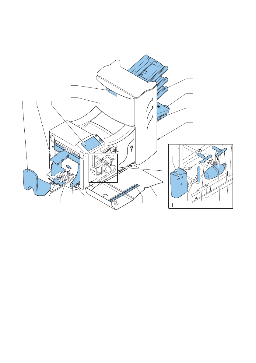
2. GENERAL
2.1 Denominations
E
A B C
D
F
G
H
I
N
Q OPRST
A Envelope catch tray K Sensors
B Envelope slide L Bellows
CDisplay with operating buttons M Handle for clearing stoppages
D Upper unit N Water reservoir
E Locking hand grip upper unit O Side cover (opened)
F Document feeders P Ruler
GCollator arm Q Thumb wheel for side guide
H Collator area adjustment
I Power inlet, power switch R Side guides envelope hopper
J Knobs for clearing stoppages S Knob for separation adjustment
T Envelope support bracket
6
JM
JKL
Page 9
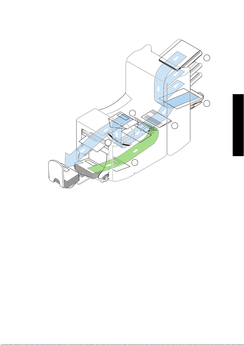
2.2 Function Description
The system consists of the following areas:
1
2
5
3
6
4
1 Document Feeders The machine selects documents from the feeders according to
the applicable job options.
2 Collating area The documents are collected in the collating ar ea before they
are transported to the folding area.
3 Folding area In the folding area, the document(s) are folded according to
the job specifications.
4 Envelope feeder The envelopes are picked up and transported to the insert
position inside the machine.
5 Inserter After the folded package of documents is inserted into the
envelope, the glue of the envelope is moistened and the
envelope is closed.
6 Operating panel The machine is programmed and operated from the operating
panel. This panel consists of a touch screen and a separate
Start, Stop and Clear button.
ENGLISH
7
Page 10

2.3 Display
The machine has a graphical touch screen.
A touch screen sensor is a clear glass panel with a touch responsive surface. The touch
sensor/panel is placed over a display screen so that the responsive area of the panel
covers the viewable area of the display.
This display shows functions and/or buttons, which can be operated by pressing a finger
directly on the touch screen on the relevant function or button. The interface recognizes
the location of the pressure point and when this is located within the defined area of a
button, the user interface reacts with ‘pressing’ this button.
In this way , the user can simply operate the machine by pressing on the displayed buttons
and/or functions.
Caution
The display is covered with a thin pressure-sensitive layer. To avoid permanent damage of
the display, do not use sharp objects to press on the display.
8
Page 11
3. OPERATING INSTRUCTIONS
3.1 Installation
Warning
You can severely damage the machine if it is connected to the incorrect power supply.
Before plugging in the machine, check if the local voltage is the same as the voltage
mentioned on the type plate.
Incidence of light can cause disturbing reflections in the display, resulting in reduced
readability . If necessary, change the position of the machine to improve the readability for
the operator.
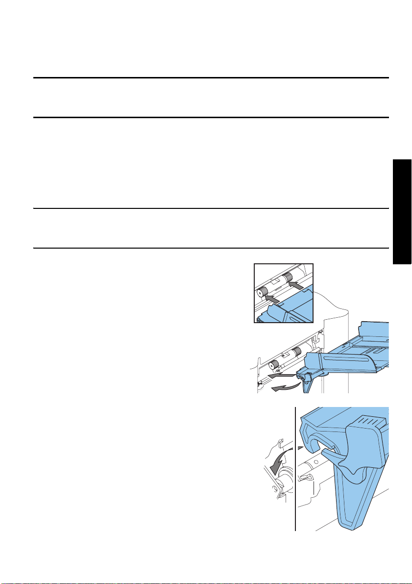
3.2 Preparation Document Feeder Trays
Note
The machine can be delivered with a tray to manually adjust the separation. However, this
tray fits in all positions, this adjustment is only possible when fitted on the lowest position
(position one).
Place the document feeder trays in position.
1. Hold the document feeder slightly inclined as
shown in the figure.
2. Place the front end of the document feeder tray
underneath the two black rollers.
3. Move the document feeder tray upwards (lifting
the black rollers), until it is possible to “hook”
the feeder into place.
ENGLISH
4. Move the document feeder tray towards the
machine and move the hooks over the mounting
points (on both sides).
5. Let the document feeder tray rest on the
machine.
9
Page 12
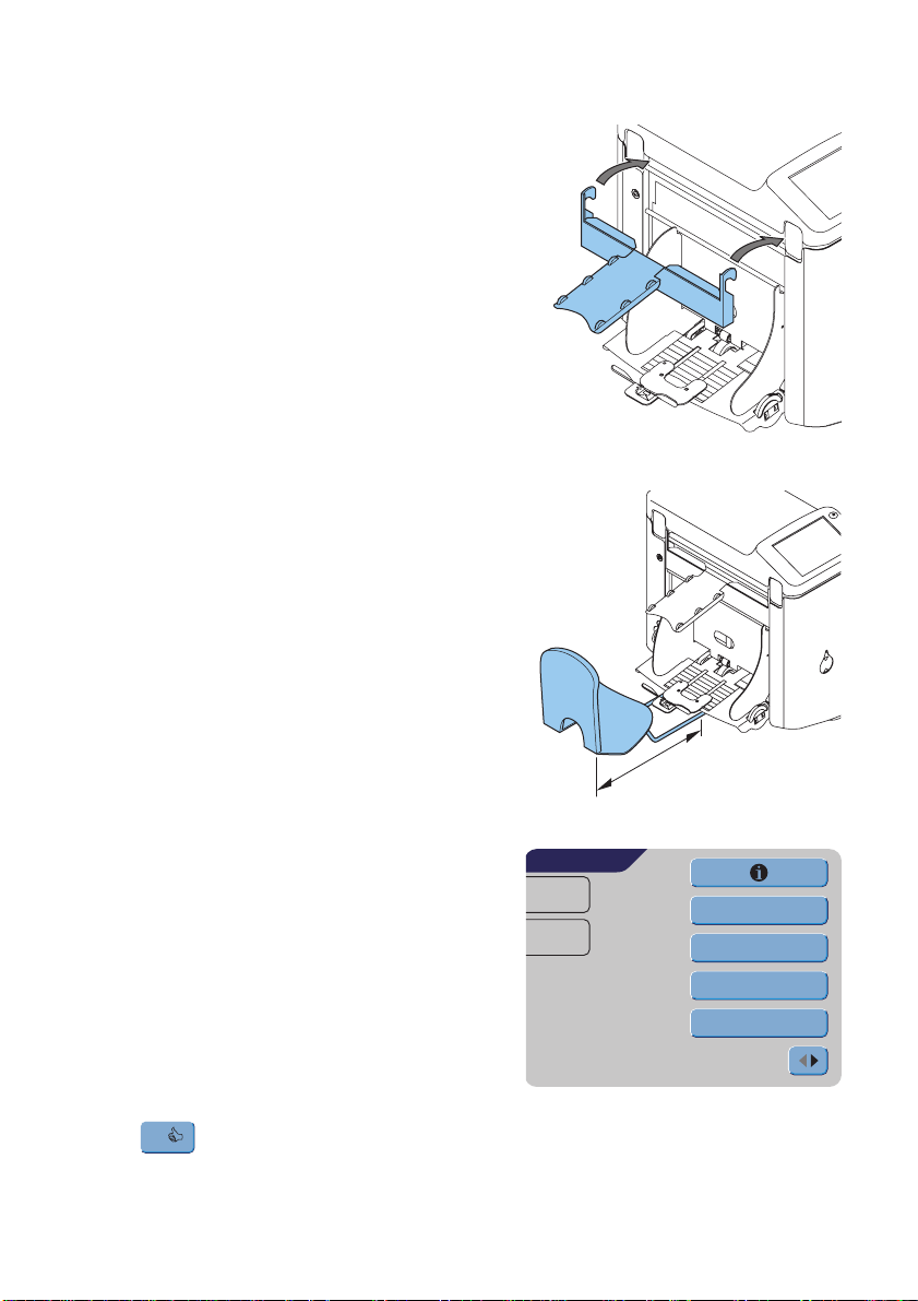
Slide and Envelope Catch Tray
1. Attach the slide as shown in the figure.
2. Position the envelope catch tray into the holes
underneath the envelope hopper as shown in the
figure.
The distance A should be approximately 1.5 x
the envelope height.
3.3 Starting Up
1. Connect the machine to the main power
supply.
2. Use the power switch to switch the machine ON.
The software will ask you to select the required
language.
3. Select the required language for the display.
4. The software will ask you i f you w ant the “ select
language option” to be displayed every time the
machine is switched on. Select either Yes or
No.
5. Press .
OK
The Main Menu screen 1/2 will be displayed.
10
MAIN MENU 1/2
JOB 1
Total:
0
A
other job
Test run
Counters
AutoSet
Page 13
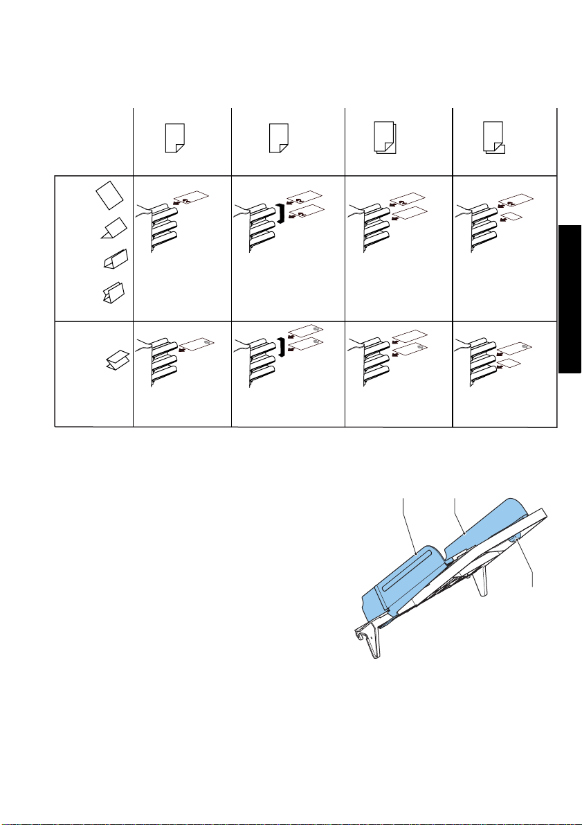
3.4 Loading Documents Document Orientation
feeder swap
Address carrier in upper
linked pair feeders.
Face up and leading.
Address carrier in lower
linked pair feeders.
Face down and trailing.
no fold
single fold
letter fold
double
parallel fold
zig-zag fold
one document
Address carrier in
upper feeder.
Face up and leading.
Address carrier face
down and trailing.
Adjusting Side Guides
1. Loosen knob B half a turn.
2. Move the side guides outwards.
3. Place a small stack of documents between the
side guides.
4. Move the side guides A and C to the document,
so the documents have just enough space to
slide between the side guides.
5. Tighten knob B.
two documents
Address carrier in
upper feeder.
Face up and leading.
Address carrier in lower
feeder.
Face down and trailing.
document + enclosure
Address carrier in upper
feeder.
Face up and leading.
Address carrier in upper
feeder.
Face down and trailing.
CA
ENGLISH
B
Document Separation
The term ‘Document separation’ refers to the
adjustment required for separating the upper
document from the rest of the documents in the
stack. This prevents documents being picked up from the stack at the same time.
The document separation for the automatic feeders is set automatically.
The special feeder (fitted in the lowest, first position) can be manually adjusted.
Adjust the manual document separation as follows:
11
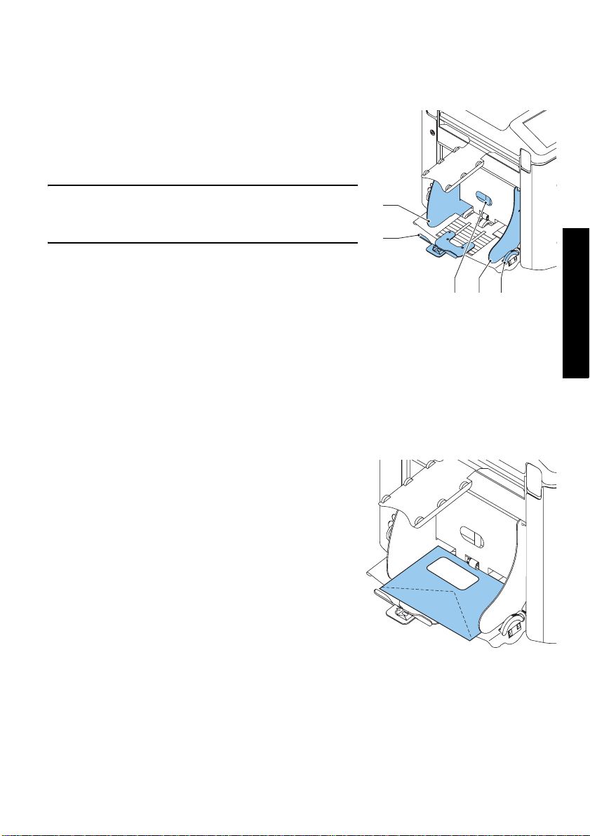
Page 14

1. Remove trays 2 and 3:
- Push the handle on the left side of the tray
down.
- Lift the tray to unhook it, and th en pull it from
the feeder.
2. Push knob B until it clicks and stays in place,
and then turn it counterclockwise as far as
possible.
3. Lower the left side guide A. The feed rollers will
move up.
4. Place a document on the feeding tray.
5. Push the document, as far as possible into the
machine, without damaging it.
6. Raise the left side guide A until it clicks into place. The feed rollers will move down.
7. Slide the document further into the machine until it stops.
8. Turn knob B clockwise until a slight resistance is felt when moving the document in
and out the machine.
If you feel too much resistance, turn knob B counterclockwise.
9. Remove the document.
10. Pull back knob B.
11. Place a stack of documents in the document feeding tray.
12. Fit the removed feeder trays 2 and 3 (refer to “Document Feeder Trays” on page 9).
A B
Feeding Documents
1. Turn the left side guide A downwards
The feed roller will be lifted.
2. Place a stack of documents between the side guides.
3. Turn the left side guide A upwards.
12
Page 15
3.5 Loading Envelopes Adjusting Side Guides
Adjust side guides C by rotating thumbwheel D, so
that the envelopes:
- fit exactly between the side guides.
- can move freely.
NOTE
If the distance between the side guides is too large,
the envelopes will twist sidewards, when transported
into the machine.
C
B
Envelope Separation
DCA
1. Turn knob A counterclockwise as far as possible.
2. Slide an envelope (with closed flap) between the rollers in th e machine and turn knob
A clockwise until a slight resistance is felt when moving the envelope in and out of the
machine.
When the resistance is too high, turn knob A counterclockwise, until only a slight
resistance is felt.
Feeding Envelopes
1. Place the bottom envelope between the rollers
(flap down and trailing - bottom side of envelope
pointing to machine).
2. Loosen the stack of envelopes and place the
stack on top of the bottom envelope.
3. Shift envelope support B in or out, so that the
flap side of the envelope is lifted approximately
20 mm (0.8”).
Turn envelope support B so the weight of the
envelopes is distributed evenly on both sides.
ENGLISH
13
Page 16
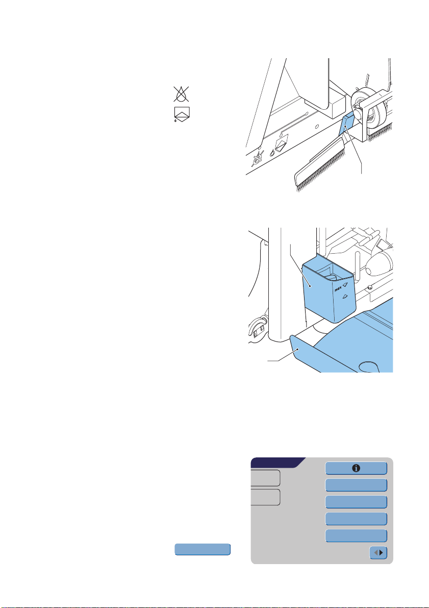
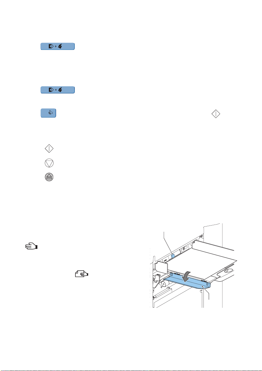
3.6 Sealing Envelopes
Switch the envelope sealing ON or OFF.
1. Lift the handgrip to open the top cover.
2. Shift the blue handle A towards to disable
the envelope sealing or towards to enable
the envelope sealing.
3. Close the top cover.
When the sealing of the envelopes is enabled, the
sealing liquid reservoir must be filled.
4. Open the front cover A.
5. Fill the reservoir B to the “Max” level indication
with sealing liquid.
6. Close the front cover A.
Before starting the job, wait approximately 5
minutes for the brushes to moisten.
A
B
3.7 AutoSet
TM
A
The AutoSetTM feature automatically adjusts all
machine settings.
When AutoSet
TM
is started, the machine will pick one sheet from each filled feeder.
The picked documents will be folded (if necessary) and inserted into an envelope.
Using AutoSet
1. Load envelopes.
2. Make sure there is sufficient sealing l iquid in the
sealing liquid reservoir. If the reservoir has just
been filled, wait approximately 5 minutes for the
brushes to moisten. See “Sealing Envelopes” on
page 14.
3. Load the documents face up and leading.
4. From the Main Menu 1/2 press r
TM
AutoSet
MAIN MENU 1/2
JOB 1
Total:
0
other job
Test run
Counters
AutoSet
14
Page 17
5. After a few seconds, the AutoSet
appear.
6. Press to load one envelope to the
insert position in the machine.
7. The envelope is visible through the window in
the top cover.
1x
TM
display will
AutoSet
1x
1x
Insert position
ESCAPE
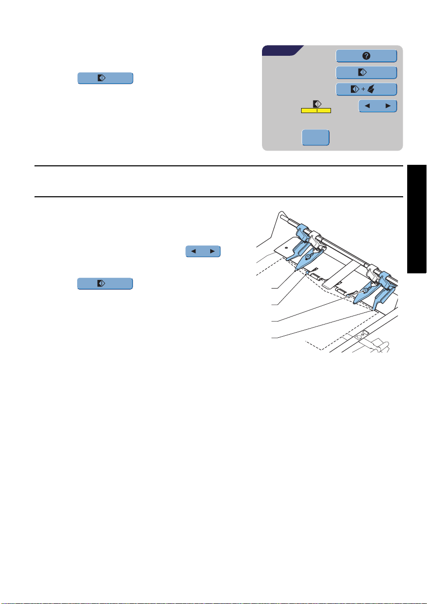
Insert Position
Note
This adjustment must only be checked in case of problems or when changing the envelope
type.
Check if the flap folding line is positioned
underneath the green roller B. If not adjust the
Insert position as follows:
1. Press on the left or right side of to
adjust the insert position to the left or the right.
ENGLISH
2. Press to load a new envelope into
the insert position
3. Recheck the insert position, and adjust as
required.
4. If necessary adjust the “envelope insert
fingers”:
- Open the top cover.
- Adjust the outer fingers D approximately 5 - 10 mm (0.2 till 0.4”) from the edges of
the envelopes.
- Loosen the knurled knobs C.
- Adjust the fingers A so that the tip is approximately 5 mm (0.2”) inside the
envelope.
- Tighten the knurled knobs C.
1x
A
B
C
D
15
Page 18
Address Position
1. When the envelope position and the position of the fingers is correct,
press to load a folded sheet into the envelope.
The envelope will be sealed (when enabled, refer to “Sealing Envelopes” on page 14)
and ejected to the envelope tray.
2. Check the position of the address in relation to the address window in the envelope.
3. If necessary, press the Up or Down button to adjust the address.
1x
4. Press to make another test run.
5. Recheck the position of the address, and adjust as required.
6. Press to leave this screen to return to the main menu or press the button
to immediately start the job.
OK
1x
Starting the Job
• Press the button to start the job.
• Press the button to stop the job. The machine will stop immediately.
• Press the button to clear the document path to prepare the machine for a new job.
3.8 Daily Mail
To process documents or sets of documents, which can not be processed automatically,
the top feeder is equipped with a daily mail switch.
Switch to Daily Mail function:
1. Select or change to a job where the Daily Mail
function is set to ON.
The Daily Mail function can be recognized by the
icon in the Job info screen.
2. Turn left side guide A of the upper tray down.
3. The Daily Mail handle B will become visible.
Move the handle to to enable the Daily
Mail function.
4. Turn left side guide A upwards.
5. Place the document or document set in the
feeder.
If necessary adjust the side guides. Refer to
“Adjusting Side Guides” on page 11.
B
A
16
Page 19

6. Press the button to start the job.
The document or document set will be folded and inserted in the envelope as
described in the selected job.
7. Place the following document or document set in the feeder. The machine will keep
running to process the inserted document or document set.
8. When finished with Daily Mail, press the button to stop the job.
9. Turn left side guide A down.
10. Move the Daily Mail handle to the ‘AUTO’ position to disable the Daily Mail and to
enable the automatic document separation.
3.9 Other Menu Options
After starting up, the Main Menu 1/2 screen will
appear.
The screen shows the selected job number and the
total number of envelopes that have been processed
using this job.
• Press the b utton to start the job.
• Press the button to stop the job. The machine
will stop immediately.
• Press the button to clear the document path
to prepare the machine for a new job.
The Main Menu 1/2 will be displayed.
MAIN MENU 1/2
JOB 1
Total:
0
other job
Test run
Counters
AutoSet
ENGLISH
Job Info
• Press to display all relevant
information about the selected job.
Refer to “Job Information” on page 22 for a
detailed explanation of the screen.
• Press to return to the Main menu screen
ESCAPE
JOB INFO
JOB 1
114
108/216
ESCAPE
3
2
1
1 297
b
17
Page 20

Other Job
Press to select another predefined
job.
1. Press to select another job number.
2. Press to confirm the selected job.
other job
The screen shows the job options of the relevant
job. (For a description of the items, refer to the
previous page).
OK
OTHER JOB
JOB 1
108/216
114
Select job
ESCAPEOK
3
2
1
1 297
b
1
3. Press to leave this screen without
ESCAPE
changing job.
Test Run
Press to display the Test Run screen.
1. Press to load a new envelope into
Test run
1x
the insert position. This gives the possibility to
check the insert position of the envelope.
2. Adjust the position by pressing on to
adjust the insert position more to the left or the
right. (Refer to “Insert Position” on page 15).
Press to load a new envelope into
1x
the insert position and check the condition again.
3. Press to confirm the insert position.
OK
4. When the envelope position and the position of the fingers is correct, press
1x
to load a folded sheet in the envelope.
The envelope will be sealed (when enabled, refer to “Sealing Envelopes” on page 14)
and ejected to the envelope tray.
5. Press to leave this screen without changing settings.
ESCAPE
TEST RUN
JOB 1
Total:
0
OK
Insert position
ESCAPE
1x
1x
- Press the button to start the job.
- Press the button to stop the job. The machine will stop immediately.
- Press the button to clear the document path to prepare the machine for a new
job.
The Main Menu 1/2 will be displayed.
18
Page 21

Counters
Press to display the Counters screen.
1. Press to reset the counters to 0.
2. Press to confirm possible changed
Counters
Reset counters
OK
settings and to return to the Main Menu.
3. Press to leave this screen without
ESCAPE
COUNTERS
JOB 1
Total:
0
OK
ESCAPE
Reset counters
Stop at:
OFF
changing settings.
- Press the button to start the job.
- Press the button to stop the job. The machine will stop immediately.
- Press the button to clear the document path to prepare the machine for a new
job.
The Main menu 1/2 will be displayed.
4. Press to program the stop counter.
5. Enter the number of envelopes that must be
processed with the numeric keys.
6. Press to confirm possible changed
OK
settings and to return to the previous screen.
7. Press to return to the previous screen
ESCAPE
COUNTERS
OK
Stop at:
1
4
7
0
3
2
6
5
9
8
0
without changing settings.
ENGLISH
CE
ESCAPE
Main Menu 2/2
• Press will bring you to the second main menu
screen 2/2.
Also this screen shows the selected job number and
the counters, indicating the programmed number of
envelopes to do as well as the total number of
envelopes that have been processed using this job.
MAIN MENU 2/2
JOB 1
Total:
0
Display setting
Job menu
Supervisor menu
19
Page 22

Display Settings
Press to change settings for the touch
Display setting
DISPLAY SETTINGS
screen display.
enables you to change the contrast of the
display. The gra phic shows the contrast setting.
enables you to adjust the volume of the
OK
ESCAPE
sound signals. The graphic shows the volume setting.
• Press to confirm changed settings.
• Press to return to the previous screen without changing settings.
OK
ESCAPE
Job Menu
The starts the job menu.
Job menu
This menu enables the creation, deletion and/or
editing of jobs. To prevent jobs being edited or
deleted without informing the ‘job owner’, this menu
is protected by a PIN-code.
This job menu will be described in “Job
Programming” on page 21.
• Press to return to the previous screen
ESCAPE
without changing settings.
JOB ACCESS
Enter pin code
_
2
1
5
4
8
7
0
3
6
9
CE
ESCAPE
Supervisor Menu
Pressing the gives access to system
settings.
The supervisor menu therefore is restricted and
protected by a PIN-code.
The supervisor menu will be described in “Supervisor
Menu” on page 20.
• Press to return to the previous screen
without changing settings.
• Press to return to the Main Menu 1/2.
Supervisor menu
ESCAPE
20
SUPERVISOR ACCESS
Enter pin code
_
1
4
7
3
2
6
5
9
8
0
CE
ESCAPE
Page 23

4. JOB PROGRAMMING
4.1 Job Menu
The job menu is protected with a PIN code, to prevent unauthorized editing or deleting
jobs.
To enter the job menu:
1. From the Main Menu 1/2 press and .
2. Enter PIN-code 2546 to enter the job menu.
The job menu contains 5 buttons, which enable
different functions. These functions are described in
the following subchapters.
• Press to see the details of a certain
job.
Refer to “Job Information” on page 22.
• Press to create a job from scratch.
Create job
Refer to “Create Job” on page 23.
• Press to change a job. Refer to “Edit
Edit job
Job” on page 30.
Job menu
JOB MENU
JOB 1
Create job
Edit job
Copy job
Delete job
ESCAPE
ENGLISH
• Press to copy a job. This copied job can be edited. In this way it is
Copy job
possible to create a new job, which resembles another job.
Refer to “Copy Job” on page 30.
• Press to delete a certain job, which is no longer necessary.
Delete job
refer to “Delete Job” on page 31.
• Press to return to the Main Menu.
ESCAPE
21
Page 24

4.2 Job Information Job Info
Press to display all relevant
information about the selected job.
JOB INFO
JOB 1
Gives information about the envelope size
(ISO format or height in mm).
108/216
114
ESCAPE
3
2
1
b
Shows the type of fold.
3
2
1
Shows the feeders selected to pull documents from (black is selected).
The sign below this icon shows if the document double feed detection for the
relevant feeder is switched ON - or OFF - .
The number under this icon indicates the number of sheets that must be pulled
from the relevant feeder.
Is the indication for daily mail.
Below this icon, the format of the document in the relevant feeder is indicated
(ISO standard or height in mm).
3
2
This sign indicates that the relevant feeders are linked. This means that when
one feeder is empty, the system automatically starts pulling documents from the
other feeder.
The sign below this icon tells whether the Optical Mark Recognition (OMR) for the
selected feeder is switched ON - or OFF - .
1 297
Press to view the Optical Mark Recognition (OMR) settings for this job. This button is
only available when OMR is installed and when OMR is switched ON in this job.
ESCAPE
Press to return to the Main Menu screen.
22
Page 25

4.3 Create Job
• Press in the Jobs menu to create a
Create job
new job. This job must be stored under a job
number. The screen will show the lowest free job
number.
• Press or to select a higher or lower
free job number (if available).
• Press to confirm the selected free job
OK
number and to go to the next screen
or press to return to the previous screen.
ESCAPE
Job Settings
After pressing the Job Settings screen will be
displayed.
The following settings are available:
Envelope settings
Document settings
Fold setting
Optical Mark Recognition (OMR) settings (if installed)
OK
CREATE JOB
JOB 9
OK ESCAPE
JOB SETTINGS
JOB 9
ESCAPESAVE
Select job
name
9
ENGLISH
Test run
Double feed control settings
name
Job name settings
Mailing/Franking settings (if available)
Press each button to set the relevant job item. Each of these settings is described below.
• Press to view all relevant information about the selected job.
• Press to save the job with the entered settings under the specified job numb er
SAVE
and name.
• Press to return to the previous screen without saving the entered job.
• Press to perform a test run with the present settings. Refer to page 18.
ESCAPE
Test run
23
Page 26

Envelope Settings
Use this screen to enter the properties of the
envelopes to be used.
At the top of the screen, three selection buttons are
displayed, from which one can be selected. The
selected settings button will be highlighted yellow.
ENVELOPE SETTINGS
JOB 8
C6/5
• Press to select an envelope which is fed
into the machine with a closed flap.
ESCAPEOK
50
• Press to select an envelope which is fed
into the machine with an opened flap.
• Press to set the job without inserting the documents in envelopes (no envelope
mode). This can be useful for jobs where documents only have to be sorted and/or
folded.
• Press to enter the dimensions of the envelope and/or the envelope flap.
A numeric keypad will be displayed to enter the applicable dimensions.
It is also possible to select ISO standard envelopes or dimensions in inches (depending
on the installation settings).
• Press to confirm changed settings or press to return to the previous
OK ESCAPE
screen without changing settings.
Document Settings
Use this screen to set the document formats
and the number of documents to be pulled
from the different feeders.
• Press to set the number of sheets for the
different feeders.
- Press to select a feeder. The selected
feeder will be highlighted.
DOCUMENT SETTINGS
JOB 8
3
1
2
1
1
1
ESCAPEOK
- Press or to enter the number of
sheets that must be pulled from the
highlighted feeder.
When the number of documents is 0, the relevant feeder will be de-selected.
24
Page 27

• Press to enter the document height. The
height or the ISO format of the document will be
displayed next to the relevant feeder.
- Press to select a feeder. The selected
feeder will be highlighted.
DOCUMENT SETTINGS
JOB 8
3
2
100
1
100
A4
- Press to display a numeric keypad to
enter the exact dimension of the document.
CE
Press to clear the displayed dimension and
ESCAPEOK
to enter a new dimension.
Dimensions can be entered in millimeters, inches or as standard ISO paper
dimensions (depending on installation settings).
The machine will not allow entering dimensions outside of technical ranges.
Feeder 3 (top tray) cannot handle documents smaller than 115 mm (4.5”), unless the
Intermediate Transport Option is installed. When Intermediate Transport is installed,
the minimum document height is 90 mm (3.5”).
• Press to link two feeders. This function allows
for filling two adjacent feeders with the same
DOCUMENT SETTINGS
JOB 8
documents. When the first feeder is empty, the
system automatically swaps to the other feeder.
3
A4
2
100
1
100
- Press to select two adjacent feeders. The
selected feeders will be highlighted
- Press to link two highlighted feeders.
ESCAPEOK
The will be displayed between the selected
feeders.
Note
When linking two feeders, the program will automatically equal the number and format of
the documents in the selected feeders.
ENGLISH
• Press to enable the Daily Mail function.
The Daily Mail function allows operators to process
process documents, or sets of documents,
which can not be processed automatically.
This function is only available for to top feeder.
(Refer also to “Daily Mail” on page 16).
The top feeder will automatically be selected.
• Press to enable the Daily Mail function and
press again to disable the function.
DOCUMENT SETTINGS
JOB 8
3
2
100
1
100
ESCAPEOK
A4
25
Page 28

• Press to confirm changed settings or press to return to the previous
OK ESCAPE
screen without changing settings.
Fold Settings
This screen enables the adjustment of the folding
dimensions.
The following choices are available:
FOLD SETTINGS
JOB 8
No fold (no settings required)
108
Single fold
Letter fold
ESCAPEOK
216
Double parallel fold
Zig-zag fold
Except when no fold is required, the display shows a simple diagram of the document with
the fold positions.
• Press next to a fold to display a numeric keypad. Enter the required position of the
relevant fold.
• Press to clear the displayed dimension and enter a new dimension.
• Press to confirm changed settings or press to return to the previous
CE
OK ESCAPE
screen without changing settings.
26
Page 29

Fold Positions
Fold type Minimum position Maximum position
Single fold 75 mm (2.95”) Longest document length
minus 25 mm (0.98”)
Letter fold First fold 75 mm (2.95”) Longest document length
minus 50 mm (1.97”)
Second fold Position first fold
plus 26 mm (1.02”)
Zig-zag fold First fold 75 mm (2.95”) Longest document length
Second fold Position first fold
plus 25 mm (0.98”)
Double parallel
First fold 75 mm (2.95”) Longest document length
fold
Second fold Position first fold
plus 25 mm (0.98”)
Longest document length
minus 25 mm (0.98”)
minus 100 mm (3.94”)
Longest document length
minus 75 mm (2.95”)
minus 51 mm (2.0”)
Longest document length
minus 25 mm (0.98”)
Note
The display will indicate when entered positions are out of range.
Optical Mark Recognition Settings (Option)
For a full function description, see chapter “Optical
Mark Recognition OMR (option)” on page 34.
Use this screen to enable or disable the OMR function
and to adjust the basic settings for OMR.
• Press to select a pre-programmed reading
code. Each time the button is pressed, the next
code is selected.
With this same button it is possible to select OFF,
which means that the OMR is disabled.
The number of different codes available depends
on the installed options.
• Press to enable a numeric keypad and to enter the position of the first reading
mark on the sheet, measured from the top.
• Press or to enter the maximum number of sheets in the set of documents.
OMR SETTINGS
JOB 8
3
2
1
ESCAPEOK
OMR
100
max
6
ENGLISH
27
Page 30

Note
The maximum number of sheets in a set is 25. When the number of sheets exceeds 6 or
8, depending on the fold, the document can no longer be folded. In this case, the
maximum length of sheets should be set to 148 mm for a C5/6 envelope. Also make sure
that the fold setting is No fold.
Ignoring this will certainly lead to stoppages.
When the maximum number of sheets exceeds the programmed maximum number of
sheets in a set, the machine stops and error VT:134 will be displayed. After removing the
set and pressing the RESET button, the machine will start and repeat the process until an
insert or divert mark is encountered, error VT:135 (final set part) will be displayed.
• Press to view the programmed OMR
codes.
Refer to “OMR Codes” on page 35 for a description
of the OMR codes.
• Press to return to the previous OMR
OK
settings screen.
Double Feed Control Settings
This screen is used to set the Double Feed Controls
(DFC) settings for the different feeders ON or OFF.
Press to select a feeder. The selected feeder will
be highlighted.
• Press to switch the DFC control ON or OFF.
When switched ON, a icon is visible beside the
relevant feeder.
• Press to confirm changed settings or press
OK
ESCAPE
to return to the previous screen without
changing settings.
OMR SETTINGS
JOB 8
Line spacing
6.00 Lpi
4.23 mm
OK
DFC SETTINGS
JOB 8
Start mark
Insert on mark
Parity check
Safety mark
3
2
1
ESCAPEOK
28
Page 31

Job Name
It is possible to store the job with an easily
recognizable job name. This name will be displayed
in the Main screen during job selection.
• Enter a job name using the alpha-numeric keypad.
• Press to clear a character left of the cursor
• Press to clear all entered character s and sta rt
a b
position (backspace).
CE
again.
JOB NAME
OK
Job name:
invoices
1
abc
4
ghi
7
pqrs
/-+
tuv
a b
3
2
def
6
5
mno
jkl
9
8
wxyz
0
a A
,.:;
CE
ESCAPE
• Press to confirm changed settings or press
OK
ESCAPE
to return to the previous screen without changing set tings.
Mailing/Franking Settings (Option*)
If this machine is connected to a mailing/franking
machine, this option allows you to:
- switch automatic mailing/franking ON or OFF.
- remotely select a mailing/franking job
- set the printing/franking value (option)
• Press the top to select YES when the mailing/
franking machine must print/frank the envelopes
or PASS THROUGH to let the envelopes pass
through without printing/franking.
• When switched ON, pressing on the second will select whether the mailing/franking
value is determined by the MAILING/FRANKING MACHINE or based on the INSERTER
DATA.
• When the printed/franking value is determined by the mailing/franking machine, a
mailing/franking job can be selected with or .
• Press to confirm changed settings or press to return to the previous
OK ESCAPE
screen without changing settings.
Refer to the Appendix for an extensive description of this option.
*Ask your supplier if this option is available.
machine.
FRANKING SETTINGS
JOB 8
Value defined by
FrankingJob
ESCAPEOK
YesFranking
Franking machine
FIF job num..2
ENGLISH
29
Page 32

4.4 Edit Job
This function is used to edit and change a
programmed job.
1. After pressing the in the Job
Menu (refer to “Job Menu” on page 21), the
display will show the job information about the
presently selected job.
2. Press to select a higher or lower job
number.
Edit job
EDIT JOB
JOB 1
C6/5
108/216
Select job
ESCAPEOK
3
2
1
1A4
b
1
3. Press to confirm the selected job number
OK
and to go to the next screen
or press to return to the previous screen.
4. After pressing , the job settings screen for the selected job will be displayed.
ESCAPE
OK
All buttons of this screen are described in chapter “Create Job” on page 23.
4.5 Copy Job
1. After pressing the in the Job
Copy job
Menu (refer to “Job Menu” on page 21), the
screen will show the Copy Job screen.
2. Use or to select the job to copy from.
Press for more information on the
selected job (refer to “Job Information” on
page 22).
3. Use or to select a free job number to
copy to. A warning will be displayed when no more free jobs numbers are available.
4. Press to confirm the selected job numbers and to make a copy or press
OK ESCAPE
to return to the previous screen.
COPY JOB
JOB 1
ESCAPEOK
Copy from job
Copy to job
9
1
30
Page 33

4.6 Delete Job
1. After pressing the in the Job
Delete job
Menu (refer to “Job Menu” on page 21), the
screen will show the Delete Job screen.
2. Use to select the job to be deleted.
The screen shows the details of the selected job.
3. Press to delete the selected job number
OK
or press to return to the previous screen.
ESCAPE
DELETE JOB
JOB 5
106/212
C6/5
Select job
ESCAPEOK
2
3
2
1
b
1
A4
2
A4
1
100
ENGLISH
31
Page 34

5. SUPERVISOR MENU
The supervisor of the system has the ability to check and configure the system.
To access the Supervisor Menu:
1. From the Main Menu 1/2 press and
Supervisor Menu
.
2. Enter PIN-code 2546 to enter the Supervisor
Menu.
The following subchapters describe the functions of
the displayed buttons.
System Info
Options
Online Services
Refer to “System Info” on page 32.
Refer to “Options” on page 33.
Refer to “Online Services (Option*)” on page 33.
SUPERVISOR MENU
System Info
Options
Online Services
ESCAPE
• Press to return to the previous screen.
ESCAPE
5.1 System Info
This screen displays information about:
- the number of inserts since the last service
visit.
- The latest displayed error message.
- Information concerning software versions.
Note
When the supervisor is not able to solve possible problems, write down the installe d
software versions and the last error, before contacting the supplier.
• Press to return to the previous screen.
ESCAPE
SYSTEM INFO
Flex certificate
Counter since last visit
last error
INF: 13
An internal error occurred which
blocks job execution
Software versions
Inserter 994550 Rev- V00.18
ESCAPE
000000
0
32
Page 35

5.2 Options
This screen displays information abo ut installed
software options.
Software options are enabled using license codes.
These license codes, together with the identification
number of the machine, enable the relevant options.
The enabled and available software options are
displayed in this screen.
Contact your dealer for information about these
license codes.
OPTIONS
Chip ID:
Chip ID:
System ID:
System ID:
Installed Options:
Also available:
ESCAPE Add
OMR level 3
FLEX OMR 9 code
1. Press to activate other software options.
Add
2. Enter the license key code that you received
from the supplier to activate the relevant option
on this machine
3. Use and to navigate through the
entered characters.
4. Press to confirm the license key and to
OK
ADD OPTIONS
OKOK
License key:
2
1
abc
5
4
jkl
ghi
8
7
tuv
pqrs
0
,.:;
/-+
return to the Options screen.
5. Press to return to the Options screen without changing settings.
ESCAPE
5.3 Online Services (Option*)
This screen displays and allows for changing the
settings for the Online services.
Refer to the Appendix for a comprehensive
description of the Online Services.
• Press to return to the Supervisor Menu
ESCAPE
without changing settings.
*Ask your supplier if this option is available.
ONLINE SERVICES
ESCAPE
3
def
6
mno
9
wxyz
ESCAPE
a A
Connection
Messages
Configuration
!!Set Date and Time
ENGLISH
CE
33
Page 36

6. OPTICAL MARK RECOGNITION OMR (OPTION)
6.1 General
The folding and inserting system can be equipped with Optical Mark Recognition. This
allows the system to read special codes that have been printed on the documents. These
codes contain information about the processing of the sheets.
The sheets with the printed code are placed in the upper feeder (no. 3). Depending on the
programmed code, the other feeders can be used as selective feeders to add enclosures.
With the first four fold types, the first sheet of a set always contains the address. In case
of a zig-zag fold, the address has to be printed on the last page of the set. A full length
code is printed on every sheet of a set.
The code on the last sheet of the set contains th e insert instruction. The other sheets
carry the accumulate instruction. If a parity check is used, this is checked on each sheet.
If the set contains only one sheet, it is the “last” sheet. The code must appear in the same
location on every page regardless of the actual code length.
This option can be enabled by a special license code (refer to “Options” on page 33).
6.2 Adjustments Reading head position
The horizontal position of the reading head must be adjusted to the same position of the
printed marks on the documents. To adjust the reading head, proceed as follows:
1. Fold a document with reading code on the first
mark.
2. Open the top cover.
3. Hold the document in the middle against the
ruler.
4. Shift the reading head A so it is positioned
exactly above the middle of the reading marks.
5. Divide the paper guides B along the width of the
document.
6. When the reading head is adjusted it is possible
that paper guides have to be removed and
placed on the other side of the reading head.
34
A
B
Page 37

6.3 Document Orientation
Switch ON the OMR-function and set the position of the reading marks as described in
“Optical Mark Recognition Settings (Option)” on page 27.
Document orientation:
Fold type
no fold
single fold
Type of documents
first page
Loading positions
1
2
3
letter fold
Double
parallel fold
zig-zag fold
address
last page
(duplex printed)
OMR
start
reading
OMR
start
reading
OMR
stop
reading
OMR
stop
reading
address
Address carrier, face up and leading.
Address carrier, face down and trailing.
3
2
1
6.4 OMR Codes Printing quality
• Marks should be printed in black.
• Marks on the same sheet must have equal intensity.
• Marks must be printed on the same position on every sheet.
• For matrix printers near letter quality (NLQ) printed characters are preferred to obtain
maximum blackness (double strike).
• Be aware of background “noise”. Color changes on the form, background design, a logo
or copy on the opposite side of the sheet that will bleed through can be read by the
reading head causing disturbances of the OMR function.
• The ribbon or toner quality must be checked before printing.
ENGLISH
35
Page 38

Minimum code/basic commands
The minimum code is one mark in one line (insert).
However for reliability it is advised to use at least 2
marks.
The first line is the start mark.
A mark printed on the second line means insert. No
mark on the second line means accumulate.
Start mark
Insert/accumulate
Note
In some cases, on request of the customer, the reading of the basic commands can be
reversed by the service organization. This means that no mark is interpreted as an insert
command and that for the accumulate command a mark has to be printed.
Length
Above the first mark and below the last mark a
space of .33" (8,5 mm) must be free from
printing. This means that the minimum code area
consists of 6 lines:
- 2 lines to print the (basic) commands
- 4 lines free space
Line distance may be .1" (2,54 mm) to .4"
(6,35 mm).
8,5 mm
8,5 mm
6,3 mm
Line 1
Line 2
Line 3
Line 4
Line 5
Line 6
4,2 mm4,2 mm
Code width, character spacing and pitch
The minimum width of the code area is 7 character spaces. From left to right:
- 2 character spaces not printed (.17" or 4,2 mm)
- track mark (3 characters or .24" (6,3 mm)
- 2 character spaces not printed
Pitch 10 or 12 is accepted.
The track mark can be printed using the underline” sign (_), which must have a thickness
of at least .08" (0,2 mm).
36
Page 39

Additional marks
When it is required to control more functions in the
inserter system, the use of more marks is needed.
The following additional functions are available via
software options:
-divert mark
-stop mark
- 1 mark: selective feed from station 1
- 1 mark: selective feed from station 2
- 1, 2 or 3 marks: respectively sequence check
4, 2 and 1
- 1 mark: parity check mark (even)
Start mark
Insert/accumulate
Divert mark
Stop mark
Selective feed 1
Selective feed 2
Sequence check 4
Sequence check 2
Sequence check 1
Parity (even parity)
Safety mark
- 1 mark: safety mark
General remarks:
- The marks must always be used in the above sequence.
- If a function is suppressed, the following function will move upward one line.
- The chosen code must always be used on all material to be processed by
the Optical Mark Recognition system.
- The length of the code and the mark definition is a service setting.
- Other marks/functions are available via special codes (Flex codes)
Divert mark
The machine stops; manually remove the set from the collator. Reset and start again.
ENGLISH
Stop mark
The machine stops; manually remove the set from the collator. Reset and start again.
Selective feed mark
The machine will selectively feed an enclosure when com manded so.
Sequence check
Sheets in a stack can accidentally get out of sequence or can be missi ng. This can be
detected by the sequence check.
Each sheet has a binary code that is a part of the reading code.
Parity mark
By adding a parity mark the reading code can be checked. When the OMR-2 code is used
the sum of the marks has to be even.
37
Page 40

Safety mark
The safety mark is used as an extra security. With
skewed paper the reading head can miss part of the
reading code. In these situations the safety mark is
not read, and the system will give an error.
The safety mark also indicates the end of the
reading code.
This mark must always be present on the document
if it has been activated as an OMR code.
Example
In the figure the legend for the following example is
shown. In this example feeder station 3 is the
reading feeder. The feeder stations 1 and 2 are
selected for selective feeding.
In this example, a set of 8 sheets with two se le ct ive
feeds (station 2 and 1) and three sequence check
marks is shown.
• The first position is used for the start mark which
must be printed on every sheet.
• The second position is used for the insert/
accumulate command. The mark is printed on the
last sheet of the set (inserting is required).
• Position 3 and 4 are reserved for selective feeding
from station 2 and 1. Print a mark on position 3
when a selective feed from station 2 is required.
Print a mark on position 4 when a selective feed
from station 1 is required.
• Position 5, 6 and 7 are used for the sequence
check marks.
Normal paper flow Skewed paper flow
Start mark Start mark
Safety mark Safety mark
reading direction reading direction
mark printed
no mark printed
accumalate
insert
or
no selective feed
wanted, mark not
printed
selective feed
wanted, mark
printed
Sheet 1Sheet 2 Sheet 3 Sheet 4 Sheet 5 Sheet 6 Sheet 7 Sheet 8
reading feeder 3
selective feeder 2
selective feeder 1
38
Page 41

7. OPTIONS
7.1 production Feeder Function
The production feeder is a feeder that can be loaded with a large number of documents.
this feeder is intended to be used for Business Reply Envelopes (BRE), but it will also accept
"standard" documents up to 156 mm length.
Preparations
The production feeder should be installed at the position
of feeder no. 1.
It can be placed into position in the same way as the
other document feeders are fitted.
Proceed as follows:
1. Lift the paper feed rollers with the front edge of
the production feeder.
2. Move the production feeder forward until it hooks
behind the frame axle.
3. Connect the connector A to the socket B.
The production feeder is auto-detected by the system
when it is switched ON. This makes it easy to switch
over from the standard document hopper to the production feeder and vice versa.
Note
To allow easier installation of the production feeder, put the feeding plate in the
rear position (see section "Separation").
A
B
ENGLISH
To make use of the production feeder it is not necessary to (re-)program the jobs.
Adjusting Side guides
Adjust the side guides:
1. T ake a stack of documents/BREs and place them
in the feeder tray.
BREs with flap down and leading (top side
pointing to machine).
2. Adjust the side guides by turning the
thumbwheel G so the documents/BREs just fit
and can move without resistance.
Too much play causes skewing.
G H I J
39
Page 42

Document Separation
When the production feeder is used as an automatic separation feeder, the separation is set
automatically.
The production feeder can also be used on a feeder position with a manually adjusted
separation.
To adjust, proceed as follows:
1. Remove feeders 2 and 3.
2. Squeeze the two blue handles C and D and shift
the feeding plate F as far as possible to the
front.
3. Push knob E forward until it clicks and turn it
counterclockwise as far as possible.
4. Place a document/BRE on the feeding tray and
slide it in the machine till the leading edge is no
longer visible.
5. Push knob E forward until it clicks and turn it
clockwise till a slight resistance is felt when
moving the document/BRE in and out of the
machine.
When the resistance becomes too strong,
turn knob E counterclockwise.
6. Pull knob E back when ready.
7. Remount feeders 2 and 3.
C D F
E
Feeding Documents
1. Squeeze the two blue handles C and D.
2. Shift the feeding plate F to the rear position.
3. Loosen the stack of documents and place them in the feeder.
BREs with flap down and leading (Top side pointing to machine).
The feeding plate assembly will shift up automatically (when the system starts
processing) until documents/BREs are underneath the rubber paper pullers.
Note
When filling the production feeder, make sure that the document/BREs are positioned parallel
in relation to the feed plate to ensure correct feeding.
7.2 Intermediate Transport
This option enables the handling of smaller documents from feeder no. 3 (top tray).
Minimum document height
Without Intermediate Transport 115 mm (4.5”)
With Intermediate Transport 90 mm (3.5”)
This option is not available in combination with Optical Mark Recognition.
40
Page 43

8. MAINTENANCE
Disconnect the main power supply before performing any maintenance.
The user must not attempt to service the inserter beyond that described
in this operator manual. All other servicing must be carried out by
qualified service personnel only.
Please contact your authorized distributor.
8.1 Operator Maintenance
Maintenance
frequency
Daily • Check the system functions.
Weekly • When dirty or saturated, clean the brushes of the envelope sealer.
When necessary • When the display warns about dusty sensors, the sensors on the
Maintenance
• Keep the system in proper condition by removing dust, paper
remains, etc.
• When dirty, clean the sealing table and rubber rollers with a slightly
wetted cloth, soaked in warm water.
The machine is delivered with an extra set of brushes. To always
have one clean set available, it is recommended to soak one set in
water and use the other set.
Remove the brushes one by one by pulling them down from the
brush holder.
Replace the brushes and make sure that the studs on the brushes
are fitted in the corresponding holes in the brush holder.
• Check moistening cloth and replace if necessary.
When dirty or saturated, clean the moistening cloth and the
reservoir.
• Clean feed and insert rollers as instructed by the Service Engineer.
envelope or document path must be cleaned using the bellows
located behind the side cover (see page 6).
Place the bellows in the hole and firmly squeeze a few times to blow
the dust from the sensor.
Repeat this procedure for the hole to clean the flap sensor.
ENGLISH
41
Page 44

9. FAULT DETECTION
9.1 Error Messages
When an error occurs the display shows a screen
showing the following information:
- An indication of the area in which the error
occurred.
- An error description.
- A suggested solution next to the pointing
hand.
Press to view more information about
the error and about the possible actions to prevent
the error from recurring.
After solving the problem, press to
reset the machine (the error screen will disappear).
Reset
Reset
Envelope too short
!
Remove envelope
Envelope length measured is shorter
than expected
Check envelope type and envelope
job settings
INS: 22
Special Errors
• Reading errors (when Optical Mark Recognition is enabled)
The document stops in the collator area. The operator must remove the document(s)
from the collator area and must complete the set manually.
• Technical errors
The display shows a message. The error cannot be solv ed by operating personnel and
assistance of the service support is needed.
Warning screen
When a cover is opened, the display shows a warning screen with the message “Cover
Open" and a suggested solution “Close Cover”. The black arrow or a black feeder indicates
where the problem occurred.
42
Page 45

9.2 Clearing Jams
Jams can occur in the following areas:
1 -Feeding area
2 -Collating area
3 -Folding area
4 -Lower envelope track
1
2
3
4
For clearing jams, three sections of the system
can be opened (A, B and C).
A - Top cover to reach the folding and feeding area.
B - Collator plate to reach the collator area.
C - Front cover to reach the envelope track and
inserter area.
Lower envelope track
Remove the envelopes as follows:
1. Open the side cover C.
2. Lower and hold the handle D to the left and
remove the envelope(s) from the lower
envelope track.
3. Release the handle D.
4. If necessary, the envelopes and documents can
be transported manually by turning the blue
knob E clockwise.
5. Turn the blue knob F clockwise to manually
transport envelopes through the lower envelope
track.
6. Close the side cover.
A
ENGLISH
BC
E
F
D
C
7. Press to remove the error and restart the job.
Reset
43
Page 46

Folding area
Remove jams from the folding area as follows:
1. Open the top cover A by pulling up the handle.
2. Remove the documents from the folding area.
3. Close the top cover A.
4. Press to remove the error and restart the job.
Reset
Feeding area
Remove jams from the feeding area as follows:
1. Open the top cover A by pulling up the handle.
2. Remove the documents from the feeding area.
3. Close the top cover A.
4. Press to remove the error and restart the job.
Reset
Collating area
Remove jams from the collating area as follows:
1. Move the collator plate B down.
2. Remove the documents from the collator area.
3. Move the collator plate B up in position.
4. Press to remove the error and restart the job.
Reset
9.3 Operator Troubleshooting
1. First, write down the error.
2. Try to solve the problem by consulting the table which follows.
3. Switch the inserter OFF and ON again, to verify system operation.
4. If the error still occurs, contact your service organization.
Note
When contacting the service organization, you will also be asked for the last error
message and the software version of the installed software. To determine the software
version, refer to “System Info” on page 32.
44
Page 47

Symptom Possible cause Remedy Refer to section
The machine is
not starting after
switching ON
Machine stops
with envelope at
insert position
(flap not open)
Envelopes are
double fed
Envelope stop
skewed
Envelopes are fed
irregularly
Machine not
connected to power
Fuse blown Replace fuse below
A cover is opened Close the cover(s) Envelopes stacked
reversed in the
hopper
Envelope flap sticks Store envelopes
Wrong envelope type
used (not according
to specifications or
job settings)
Envelope separation
not correctly
adjusted
Envelopes not placed
properly in the
hopper
Side guides of the
envelope hopper are
set too wide
Hopper almost empty Refill hopper “Loading Envelopes” on
Separation set too
narrow
Side guides set too
narrow
Envelope support not
positioned correctly
Connect the machine
to the main power
power switch
Check envelope feed
adjustments. Place
envelopes correctly
in hopper
according to
specifications
Change envelopes
according to
specifications
Check separation
settings, adjust if
needed
Check and replace if
needed
Check side guides
and adjust if needed
Check separation
settings, adjust if
needed
Check side guides
and adjust if needed
Reposition the
envelope support
-
-
“Loading Envelopes” on
page 13
“Envelope Settings” on
page 24
Envelope specifications
“Envelope Settings” on
page 24
“Technical
specifications” on
page 48
“Loading Envelopes” on
page 13
“Loading Envelopes” on
page 13
“Loading Envelopes” on
page 13
page 13
“Loading Envelopes” on
page 13
“Loading Envelopes” on
page 13
“Loading Envelopes” on
page 13
ENGLISH
45
Page 48

Symptom Possible cause Remedy Refer to section
Flap is wrinkled
and sometimes
not opened
Fingers are placed
on top of the
envelope
Machine stops
while inserting
(jam at the
inserting point)
Envelope not within
specifications
Flap sticks Store envelopes
Flap curled Envelopes stored or
Separation set too
narrow
Fingers adjusted too
deep into the
envelope
Envelope stops too
early
Fingers not correctly
adjusted
Inserted document
too long for envelope
Check specifications
and change
envelopes if needed
according to
specifications
manufactured
improperly
Check separation
settings, adjust if
needed
Check finger
position, adjust if
needed
Check envelope stop
position, adjust if
needed
Check finger
position, adjust if
needed
Check fold settings “Document Settings” on
“Technical
specifications” on
page 48
Envelope specifications
Envelope specifications
Envelope specifications
“Loading Envelopes” on
page 13
“Insert Position” on
page 15
“Insert Position” on
page 15
“Insert Position” on
page 15
page 24
46
Envelope throat
incorrect
Envelope glued inside Eliminate faulty
Window not glued
properly
Check envelope
specifications
envelopes
Eliminate faulty
envelopes
Envelope specifications
“Technical
specifications” on
page 48
-
-
Page 49

Symptom Possible cause Remedy Refer to section
Flap not
sufficiently
moistened
Envelope not
filled properly or
envelope flap not
closed properly
No document fed Feeder empty Refill feeder “Loading Documents” on
Skewed
documents fed
Water level low Check water level,
refill if needed
Brushes dry Check brushes,
replace if needed with
the extra soaked set
Brushes dirty Check brushes, clean
if needed
Moistening cloth dry Check the moistening
Moistening cloth dirty Check the moistening
Moistening brushes
inactive
Inserted document
too big
Document not
inserted deep enough
Separation set too
wide
Side guides set too
narrow
Side guides set too
wide
cloth, refill water tray
if needed
cloth, clean if needed
Activate the
moistening brushes
Check fold settings,
adjust if needed
Check adjustment of
envelope stop
position and fingers
Adjust the separation “Document Separation”
Adjust the side
guides
Adjust side guides “Adjusting Side Guides”
“Sealing Envelopes” on
page 14
“Sealing Envelopes” on
page 14
“Maintenance” on
page 41
“Maintenance” on
page 41
“Sealing Envelopes” on
page 14
“Maintenance” on
page 41
“Sealing Envelopes” on
page 14
“Document Settings” on
page 24
“Insert Position” on
page 15
page 11
on page 11
“Adjusting Side Guides”
on page 11
on page 11
ENGLISH
47
Page 50

10. SPECIFICATIONS
10.1 Technical specifications
Type: Inserter system for medium office use
Theoretical max.
speed
Power consumption: 100V AC / 50 Hz / 5.0 Amps
Fuse 100/115 V AC: T 5.0 A, 125 V. Time lag, 5.0 Amps rated
Approvals: EMC Certificate conform EMC-Directive
3,000 inserts per hour, depending on application
115V AC / 60 Hz / 5.0 Amps
230V AC / 50 Hz / 2.5 Amps
current, 125 V.
230 V AC: T 2,5 A H, 250 V. Time lag, 2.5 Amps rated current,
High breaking capacity, 250V.
FCC Certificate conform 47CFR, part 15
CB Certificate conform IEC 60950
UL Listed I.T.E. (Information Technology Equipment), conform
UL-IEC 60950, file E153801
Conform NEN-EN-IEC 60950 and derivates
10.2 Dimensions
Length: 30" (765mm) on covers
44.1" (1120mm) including hopper (3.5"/90mm)
and collator/document hoppers (10.5"/265mm)
50"-54" (1260-1360mm) including standard exit (catch tray)
47" (1200mm) including side exit
Width: 18" (460mm) (optional side exit is 3.5" - 7.7" outside side cover)
Height: 27" (680mm)
48
Page 51

10.3 Other general specifications
Noise level <70 sBA (68 dBa)
Operating temperature 50 - 104 degrees F (10°C - 40°C)
Power requirements 230V/50Hz (voltage tolerance: +10%/-10%)
115V/60Hz (voltage tolerance: +6%/-10%)
100V/50Hz (voltage tolerance: +6%/-10%)
Weight Whole system: 160lb (73 kg)
10.4 Document specifications
Paper quality minimum 15# bond (60 gr/m²)
maximum 62.5# bond (250 gr/m²),
when folded max 42.5# bond (170 gr/m²)
Booklets up to approximately .04" (1 mm) thickness,
depending on stiffness
Paper size Minimum width: 5.1" (130 mm)
Maximum width: 9.3" (236 mm),
when folded max. 9.1" (230 mm)
Minimum length: 3.5" (90 mm), the minimum document
length used for the upper feeder is 4.5" (115 mm)
Maximum length: 14" (356 mm)
Folding capacity Single fold - 8 sheets (max. 20# bond, 80 gr/m²)
Double fold - 6 sheets (max. 20# bond, 80 gr/m²)
Envelope sizes Standard BRE (Business Reply Envelopes)
ENGLISH
Envelope quality Minimum 20# bond (80 gr/m²)
Maximum 30# bond (120 gr/m²)
49
Page 52

10.5 Insert specifications
A B C D E F G
Minimum size mm 160 90 32 10 130 84
inches 6.3 3.5 1.25 0.4 5.1 3.3
Maximum size* mm 248 162 B-32 35 A-12** B-6 2.5***
inches 9.7 6.38 B-1.25 1.4 A-0.47** B-0.2 0.1
* Maximum insert specifications are based on si ngle sheets. When multiples are
handled, more room inside the envelope is needed depending on the application.
** When insert is more than .04" (1 mm): A-15 mm / A-0.6 inch
*** Booklets up to approximately .04" (1 mm) thickness, depending on stiffness
60 g/
60 g/
m
m
2
2
Remarks:
• The specification of the paper handl ing equipment is often wider than that of the
envelopes and documents handled. The condition of material handled will limit the
specified environmental conditions.
• We recommend that materials to be handled are stored at a temperature of 68°F (20°C)
with a relative humidity factor of 50%. If difference in temperature occurs between
store room and mailing area, the material must be stored near the machine at least 24
hours before use.
• Self-copying paper may cause rubber parts to wear quicker. The rubber used in this
machine has the best resistance to Wiggins Teape material.
50
Page 53

10.6 Terminology
Term Description
Address Carrier The address carrier is the document that carries the address of the
person for whom the mail-set is meant. The address carrier can consist
of one or more sheets, from which at least the first sheet must contain
the address. The address must remain visible while enclosures are
added and the document-set is folded. The fold type and selected
envelope must ensure that th e address is v isible be hind the window in
the envelope. For personalized mailings there is always an address
carrier present as long as envelope printing is not supported. Normally
there is one address carrier.
Address position Position of the address on the address carrier,
measured from the upper left corner. The address
position consists of a horizontal x coordinate, a
vertical y coordinate, a horizontal width w and a
vertical height h.
ENGLISH
Business Reply
Envelope (BRE)
C-fold See Letter fold.
Clear The function of an inserting system in which all mail-sets in progress
Daily Mail Capability of an inserting system to manually insert mail-sets one by
Document A document is one of the components of a mail-set. A document can
Document-set The document-set is the physical collection of address carrier an d
Envelope included in outgoing mail-sets for addressee response
purposes.
are finished and the document path is left empty.
one into the system, which are then inserted into an envelope.
Optionally, depending on settings, additiona l en closures can be added
and the mail-set can be folded. This function is intended for small
amounts of mail that each can have a different build-up.
consist of one or more sheets. Documents can be divided into address
carriers and enclosures. For personalized mailings there is always one
address carrier and an optional number of enclosures.
enclosure(s) that is under production in the Inserting System. The
document-set is completed during production and is to be inserted in
the envelope. The number of enclosures can range from 0 to the limit
imposed by the number of available feeders. Once the document set
has been inserted into an envelope it is called a mail-set.
51
Page 54

Term Description
Double Feed
Control (DFC)
Double Parallel
fold
Double Feed Control is the sensor that measures the thickness of a
sheet to check if the inserting system does not accidentally take more
sheets than intended. DFC sensors exist on Feeders (double sheet
detection). Currently, DFCs on Formax inserting systems perform
relative measurements, which means that they need a cycle to 'learn'
the thickness of a sheet.
Also the length of the document is measured so partly overlapping
sheets will be detected.
The double parallel fold is a type of fold where the document is first
folded halfway and the resulting folded set is again folded halfway.
This fold is illustrated in the picture below. The position of both folds is
adjustable.
Envelope The envelope is the packaging of a mail set. Window envelopes are
Face down Situation in which the front of a sheet is facing downwards when
Face down
leading
Face down
trailing
Face up Situation in which the front of a sheet is facing upwards when placed
Face up leading Situation in which the front of a sheet is facing upwards and the top of
Face up trailing Situation in which the front of a sheet is facing upwards and the
Feeder A Feeder is a Module for the input of documents to the inserting
Feeder linking The ability to load two feeders with the same document type where
(cascade mode) the Inserting System automatically switches to a second feeder when
Feeder tray Part of the feeder that contains the stack of documents.
envelopes that have a transparent section through which the address
on the address carrier can be read. Besides the normal top-closing
window envelopes there are also bottom-closing envelopes.
placed in a document feeder.
Situation in which the front of a sheet is facing downwards and the top
of the sheet is closest to the separation unit in a document feeder.
Situation in which the front of a sheet is facing downwards and the
bottom of the sheet is closest to the separation unit in a document
feeder.
in a document feeder.
the sheet is closest to the separation unit in a document feeder.
bottom of the sheet is closest to the separation unit in a document
feeder.
system. The Feeder separates documents sheet by sheet from the
stack of documents in the feeder tray.
the first feeder is empty and vice versa. In the meantime the first
feeder can be refilled, so the inserting system can keep running
without having to stop to refill the feeders.
52
Page 55

Term Description
Flexcode OMR An OMR code for which the meaning of the OMR marks can be
programmed in a dedicated way for a specific customer. This is
normally used to support the OMR codes from other suppliers.
Insert • the action of inserting a document-set into an envelope.
• an insert is also a short, not to be folded document,
usually an enclosure.
Inserter An Inserter is the Module where the document-set is inserted into the
envelope, the envelope is closed and if necessary sealed.
Inserting System The system of all the Modules t hat cooperate to perform the inserting
function (accumulate docume nt -set, fo ld and insert) and have a single
point of control.
Job A job is an actually produced collection of mail-sets based on a certain
Job Definition at a certain point in time for a specific purpose. It
consists of:
• The Job definition used for the production
• Information about the batch size
Job counter The counter that registers the number of mail-sets that is produced as
part of a specific job.
Letter fold Fold type in which a document-set is folded twice in which the folded
flaps are on top of each other. This fold is illustrated in the picture
below. The position of both folds is adjustable.
ENGLISH
Synonym: C-fold.
Linking See Feeder Linking.
autoset The feature of an Inserting System to automatically determine its Job
autoset
productionFeeder Feeder with high capacity feeder tray (e.g. 2000 sheets A4 80gr).
Multifeed The feature of an Inserting System in which more than one sheet is
OMR Standard 1-track OMR code definition.
OMR code
definition
Operator The person operating an Inserting System.
job A job that is created with the autoset functionality.
settings by measuring the sizes of documents and envelope. From all
Feeders that are loaded one sheet will be taken. Based on the
maximum document length (which is also the length of the documentset) and the length of the envelope the fold type is determined.
taken from a Feeder.
Specifies the amount of reading marks used and the functionality
linked to each of them (how each should be interpreted).
53
Page 56

Term Description
Optical Mark
Recognition
(OMR)
Reading error Condition in which the system could not reliably read or interpret the
Reading marks Marks added to documents containing finishing instructions that can
Remote
diagnostics
Service engineer Technical engineer whose task it is to resolve problems with systems
Single fold A single fold implies the document/set is folded once ("half fold"). The
Optical Mark Recognition is intended for reading and interpreting
printed codes. These codes are one or more black marks which are
read from a document. These marks give information to the Inserting
system about how to build-up and handle a set.
OMR reading marks from a sheet.
be identified by an OMR head and interpreted according to the used
OMR code definition.
The feature that makes it is possible to analyze a problem (on an
Inserting System) from a remote location.
in the field. Besides dealing with problems, service engineers are also
responsible for preventive maintenance.
fold position is adjustable. This fold is illustrated in the picture below:
Stacker Used as storage for filled envelopes.
Stop counter Counter which sets the amount of envelopes to be filled. After filling
Supervisor Person who is responsible for the technical state of the machine.
Test run A test run is intended to validate the settings of the Inserting System:
Tray Contains a stack of paper for a printer or inserter. This paper is
Vertical
Transport
Optional horizontal unit can be delivered.
this amount of envelopes the system will stop (even during a clear).
Normally a supervisor has access to programming functions, which are
restricted for standard users.
• Inspect and adjust the stop position of the envelope.
• Check the fold settings for one set.
• Check whether the address is correctly positioned behind the
envelope window.
supplied to the machine for further processing.
The vertical transport section between feeders and collator.
54
Page 57

Term Description
Z-fold A Z-fold document is folded twice in such a way that each folded flap
is on a different side of the folded document, resulting in a
Z-shape. This fold is illustrated in the picture below. The position of
both folds is adjustable.
Synonym: zigzag fold
ENGLISH
55
 Loading...