

Page 1

2200 Series
AutoSeal
®
Page 2

Page 3

Operator’s Manual 2200 Series
CONTENTS
1. GENERAL 5
2. SPECIFICATIONS 6
3. PROPER HANDLING OF THE MACHINE 7
4. SAFETY INSTRUCTIONS 8
5. SAFETY FEATURES 10
6. BASIC COMPONENTS OF THE MACHINE 11
7. ELECTRICAL CONNECTION 12
8. FD 2200 & 2200-EX AIR FEEDER 13
9. FD 2250 PILE FEEDER 19
10. REGISTER TABLE 29
11. BUCKLE FOLD UNIT 31
12. TRANSFER BRIDGE 33
13. SEALING UNIT 34
14. STACKER TABLE 35
15. AUTOMATIC SETTING 36
Operator Panel 36
Setting the Counter - Main Menu COUNTER 39
Clearing the Total Counter 39
Setting the Batch Counter 40
Paper Transport Control, Double Sheet Detection - Main Menu MONITORING 42
Paper Transport Control 42
Double Sheet Detection 43
Setting the Fold Length - Main Menu SET-UP 44
Standard Folds 44
Special Folds 51
Job Saved 59
Setting the Suction Length - Main Menu SET-UP 70
Saving of Job Data - Main Menu SAVING 73
Display of the Actual Job - Main Menu JOB 78
Correction of Fold Lengths - Menu FOLD LENGTH 79
Setting the Fold Rollers - Menu ROLLER GAP 80
Setting the Delivery Rollers - Menu DELIVERY 85
Choosing the Measuring System and the Language 87
Fold Plate Setting: Three Methods 88
Display of Malfunctions 91
Service Functions 92
18. OPERATION AND TRIAL FOLDS 95
19. FINE ADJUSTMENTS AND CORRECTIONS 97
20. TROUBLESHOOTING GUIDE 101
Page 4

Page 5

pressure seal mailer con gurations including, “C”, “Z”, “V” and
between suction- and at pile feeders.
As soon as it comes up against the adjustable
the infeed rollers keep on moving.
by rollers (2) and (6); this is where the actual
plate and the infeed rollers and move it on.
Operator'sManual 2200 Series
General
5
Page 6

FD 2200
FD 2200
FD 2250
FD 2200
FD 2200-EX
FD 2250
Variable Speed:
Duty Cycle:
Dimensions:
Weight:
Delivery Requirements:
better suited for the FD2200 and FD2200-EX.
Maximum
Minimum
W x L
W x L
4 x 4.75 in
Up to 40,000 sheets per hour – based on 11” Z-Fold (279mm)
Unlimited
Approx. 1,200 lbs (45 kg)
UL applied for
Operator'sManual 2200 Series
General
6
Page 7

unsuitable applications. Responsibility lies alone with the user.
Reading the Operator’s Manual and observing the conditions for inspection and
maintenance are part of the proper handling of the machine.
representatives. Additional instructions are provided for this purpose.
Repairs and service should be carried out only by skilled personnel authorized by the
manufacturer or his representatives.
machine usage.
For regular one-shift-operation, two inspections per year is recommended.
uneven oor to a certain degree.
No harmful emissions are produced.
Read the Operator’s Manual before working with the machine.
We recommend to carry out all operations and settings in the sequence mentioned in
this manual.
Operator'sManual 2200 Series
General
7
Page 8

Operator'sManual 2200 Series
4. SAFETY INSTRUCTIONS
4.1 Safety Instructions for Transport and Set-Up
The following instructions and warnings are applied to the packing to ensure
appropriate and safe transport:
General
Top! - Transport in
upright position only!
Theses instructions and warnings must also be observed for transport within the
users premises.
For transport to other premises resp. for return shipment the machines must be
packed and provided with the same markings.
4.2 Fundamental Safety Instructions
Warnings and Symbols
The following symbols and designations are used in the manual to identify
instructions of particular importance:
General instructions and special information how to use the machine
most efficiently.
Instructions designed to prevent injury or extensive equipment damage.
!
Protect from humidity!
Fragile! Handle with care!
Basic Operation
8
The machine has been built in accordance with state-of-the art standards and the
recognized safety rules.
Nevertheless, operators and third parties may get injured when working with the
machine, or damage to the machine and to other material property may result.
The machine must only be used in technically perfect condition in accordance
with its designated use and the instructions set out in the operator's manual.
Any malfunctions, especially those affecting the safety of the machine, should
therefore be rectified immediately.
Page 9

Regular and proper cleaning contributes to a long life of the machine and a consistent quality.
Use the Formax recommended cleaner only for cleaning the fold rollers.
Do not use any solvents such as Acetone or Toluol. They would damage the nonmetal parts
Remove paper- or print powder dust from all xed and moveable parts of the machine.
Use compressed air to clean the fold plates when paper with a high degree of powder
has been folded. Carefully remove deposits in the control box with a vacuum cleaner.
up.
Operator'sManual 2200 Series
General
9
Page 10
4 Safety handwheel
Operator'sManual 2200 Series
General
10
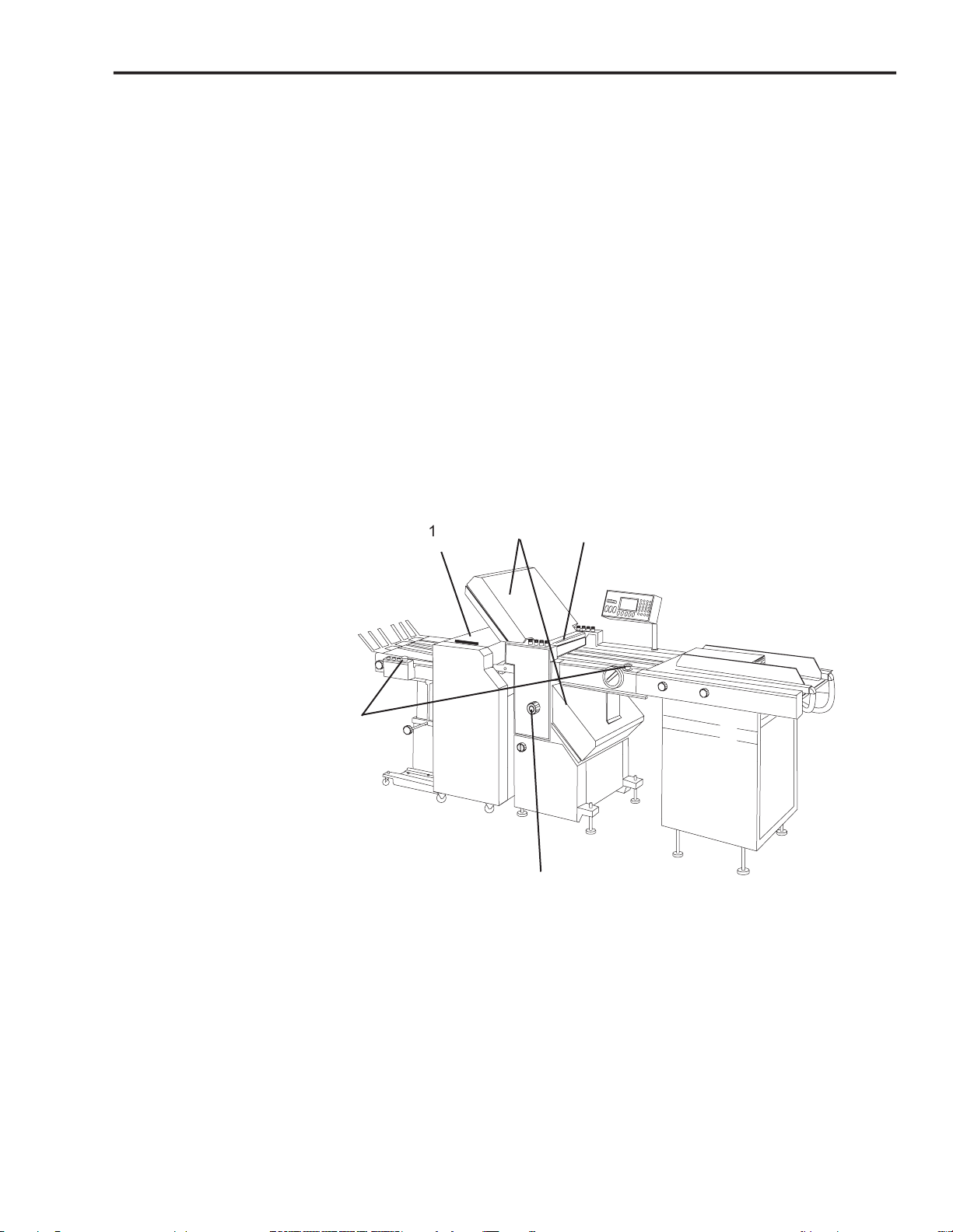
Page 11
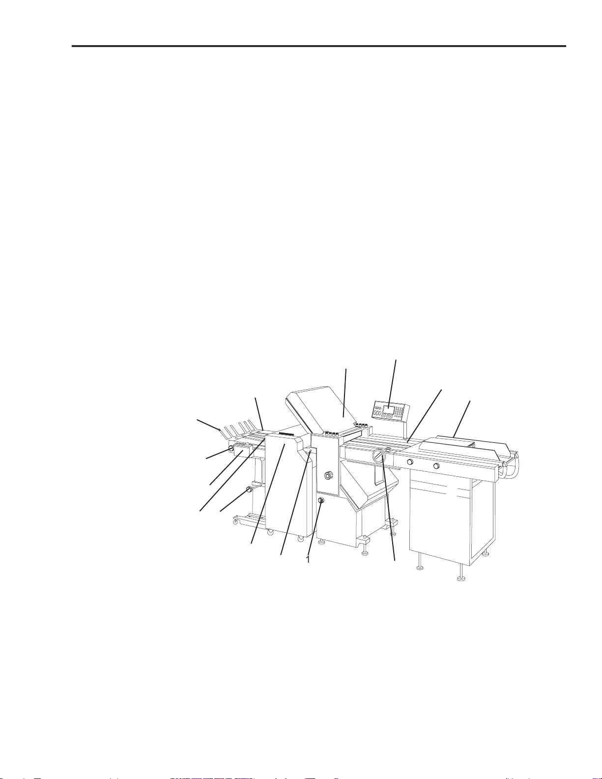
4. Register Table
4
11
Page 12
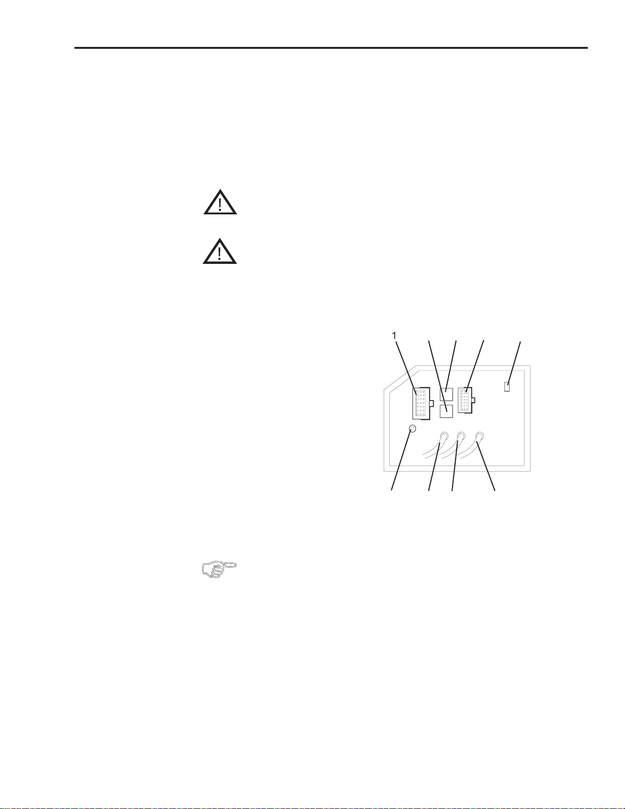
Plugs and sockets allow variable connections.
Do not bend or twist the cables sharply or place heavy objects on them -
When making or breaking any electrical connection, always rst turn
At the rear of the base of the fold unit you will nd the sockets for connecting
the various componets of the machine.
operator panel
stacker table
Plug connections are easily pulled or inserted by holding the plug with one
hand and opening resp. closing the safety bracket with the other hand.
12
Page 13
Operator'sManual 2200 Series Air Feeder
8.AIRFEEDER FD 2200 & FD 2200-EX
Principle of
Operation
Description
Theairfeederconsistsofafeederandaregistertable.
It is suitable for handling a wide variety of papers - uncoated papers as well as coated,
freshly printed or thin papers.
The sheets are separated by air and vacuum.
Air is supplied from the bottom of the stack both on the left and right side,
separating the paper in the stack which now floats in a cushion of air.
A rotating suction drum can then separate the sheets from the bottom of the paper
stack.
This principle has the advantage that paper can be continuously reloaded with the
machine running. There is no need to stop the machine.
On the register table, a transport belt, which runs at an angle, moves the sheets
against a register rail.
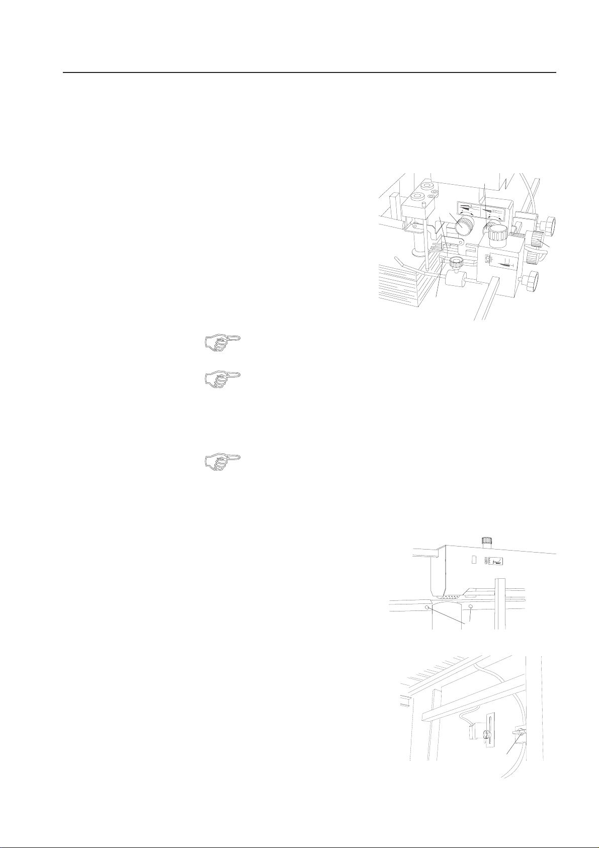
Componentsandoperatingelementsoftheairfeeder:
1 Feed table
2 Air guides left and right
3 Knobs for adjusting the air guides
4 Rear paper stop
5 Air adjustment valves
6 Suction drum with suction segment
7 Front paper stop
8 Guide rollers
9 Lever for adjusting the suction
segment
10 Lock screw
11 Window for adjustment of suction
segment
12 Vacuum adjustment valve
13 Register table
14 Ball cage
15 Handwheel
16 Lock screw
17 Lever for adjustment of sheet gap
18 Hold-down bars
19 Alignment rail
20 Adjustment wheel for changing
the infeed angle
4
5
3
5
2
7
1
3
8
6
3
20
19
14
18
16
15
17
13
11
10
9
12
13
Page 14

Operator's Manual 2200 Series Air Feeder
Setting the Format
Setting the Sheet
Separation
When setting the format, care should be taken that the sheets are fed
approximately from the center.
• Loosen the handles (1) by turning them
counter-clockwise.
• Set the left feed guide to half sheet width
with the help of the scales (2).
• Tighten the handles (1) again.
• Place a stack of about 50 sheets on the
feed table.
• Slide the right feed guide (3) against the edge of the stack.
Make sure that the sheet does not actually touch the guide. There should be
a gap of approx. 0.5 mm. The right and left feed guide should be parallel.
• Tighten the handles (4) at the right feed guide.
If the width of the paper is less than 7 cm, only one paper guide can be used.
Sheet separation is achieved by the combined action of the rotating suction drum,
the paper stop and the air.
Paper weight and type of paper have an influence on the setting.
1
2
4
3
2
1
4
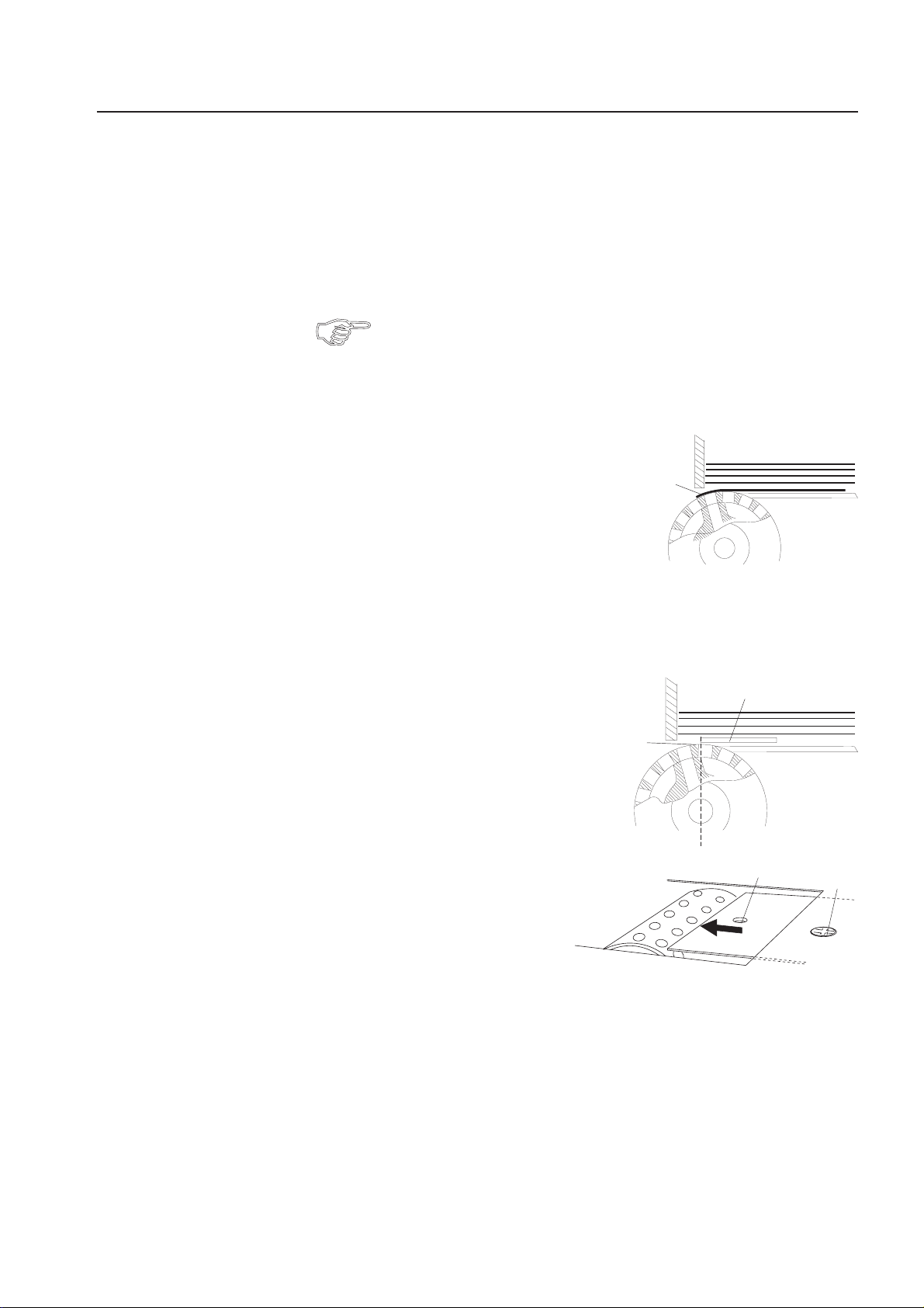
Setting the Air
A suction drum (5) separates the sheets from the
bottom of the stack.
This is achieved by the suction segment (6)
inside the suction drum.
The angle of the suction segment
with respect to the paper stop
can be changed to suit different
types of paper.
Basic setting
• Loosen the lock screw (7).
• Turn the knob (8) until the figure "6" on a red
background appears in the window (9).
• Tighten the lock screw (7).
Now the suction segment is in its zero position (10).
6
5
9
7
8
14
10
Page 15
Operator's Manual 2200 Series Air Feeder
Mosttypesofpaperwithaweightof20 to24 #canbeseparatedinthisposition.
For different paper grades, other figures must be set in the window:
-Papergradesbelow20# :7-9
-Papergradesabove24# :1-5
Setting for light paper grades:
For running light-weight paper, first try the suction segment setting as
described under "Basic Setting".
A steeper inclination is only necessary for special types of paper.
Light paper grades easily cling to the curve of the suction drum.
Therefore the suction segment must be tilted in direction of the paper stop.
The inclination of the suction segment in this direction
has the effect that the paper is wrapped around the
suction drum (1).
The sheets are easily separated from the stack and
double sheets occur very rarely.
1
In the batch counting mode it may happen occasionally that a single sheet is fed
during the interval time.
This is caused by the fact that the suction drum continues to turn during the interval
time (although without vacuum). For light paper grades the friction between paper
and suction drum may be sufficient for detaching a sheet.
To prevent this, a special plate (2) can be placed
over the suction drum. This plate, which is pulled
out of the feed table, can cover the suction drum
to its highest point (3).
Sheets are no longer affected by the friction
of the suction drum.
Proceed as follows to pull out the plate:
• Loosen the screw (4).
• Insert a screwdriver in the hole (5).
• Pull out the plate.
• Tighten the screw (4).
3
2
5
4
15
Page 16

Operator's Manual 2200 Series Air Feeder
Setting for heavy paper grades
Heavy paper grades do not easily cling to the curve
of the suction drum.
For this reason the suction segment must be tilted
in direction of the paper stack.
The inclination of the suction segment in this
direction has the effect that the paper is barely
wrapped around the suction drum (1).
This is sufficient because heavier paper grades
are more easily separated from the stack.
Vacuum:
Vacuum can be modified by means of a regulating
valve (2). This is necessary because heavy paper
grades require more vacuum than light paper grades.
The vacuum can be modified by turning knob (2).
1
2
Setting the vacuum:
For setting the vacuum, the machine must be turned on.
Exercise caution in the vicinity of rotating shafts and rollers!
Hair,loosegarmentsandjewel
!
SERIOUS INJURY MAY RESULT!
Do not get close to rotating shafts and rollers while the machine is
running and the noise-absorbing cover is open!
!
SERIOUS INJURY MAY RESULT!
Exercise caution in the vicinity of the perforating- and slitting knives!
They have sharp edges for proper function!
!
SERIOUS INJURY MAY RESULT!
• Close the valve (2) for setting the minimum effect.
• Start the machine.
• Slowly open the valve (2) by turning the knob clockwise.
Observe the sheet separation while doing this.
At first no sheets are pulled off the stack or they are pulled off irregularily.
The more the valve is opened, the smoother is the paper transport.
Make sure that much vacuum does not cause feeding of double sheets.
erymaygetcaught!
16
• Switch off the machine.
Page 17
Operator's Manual 2200 Series Air Feeder
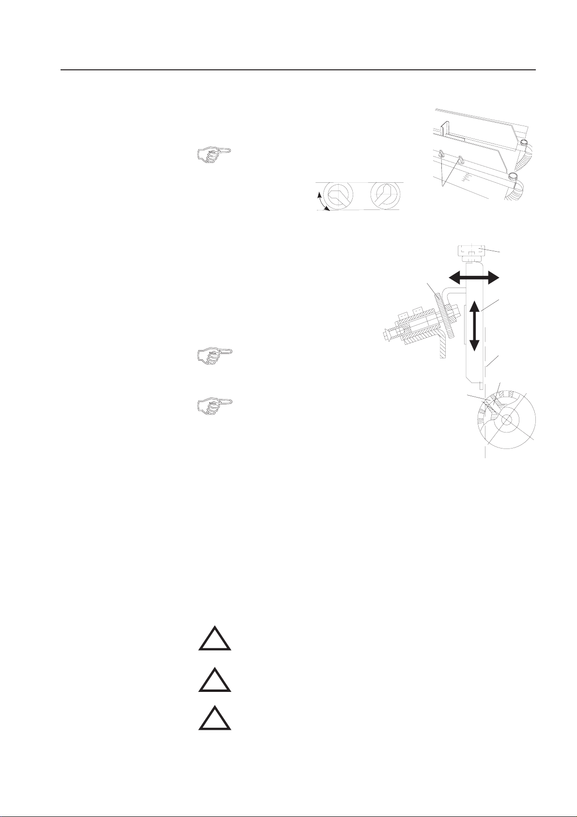
Air
•Openthevalves (1) at both air brackets.
In most cases it is sufficient to open the second
and the last valve (with respect to the format
length).
1
closed open
Front Paper Stop
The position of the front paper stop (2) can be
adjusted in a horizontal and vertical direction.
Adjusting the horizontal position:
The horizontal position of the front paper stop
determines the suction point on the paper and
in turn depends on the position of the suction
segment in the suction drum.
The inclination of the suction segment
must be set correctly before making
the horizontal adjustment.
When the suction segment is adjusted,
the horizontal position must also be
changed accordingly.
• Turn the handwheel until the openings of the suction drum (3)
are exactly above the openings of the suction segment (4).
• Adjust the horizontal position of the front paper stop in such a way that it forms
a vertical line (5) with the leading edge of the suction openings.
To achieve this, turn the knurled screw (6) counter-clockwise or clockwise.
6
3
7
2
5
4
Adjusting the vertical position:
The respective paper thickness is set by adjusting the vertical position of the front
paper stop. Proceed as follows:
• Place a stack of about 50 sheets on the feed table.
• Start the machine.
Exercise caution in the vicinity of rotating shafts and rollers!
Hair,loosegarmentsandjewel
!
SERIOUS INJURY MAY RESULT!
Do not get close to rotating shafts and rollers while the machine is
running and the noise-absorbing cover is open!
!
SERIOUS INJURY MAY RESULT!
Exercise caution in the vicinity of the perforating- and slitting knives!
They have sharp edges for proper function!
!
SERIOUS INJURY MAY RESULT!
• By turning the knurled screw (7), adjust the vertical position of the paper stop
in such a way that only one sheet is pulled off the stack.
erymaygetcaught!
17
Page 18
Operator's Manual 2200 Series Air Feeder
Positioning the
Paper Stack
Sheet Gap
• Fan the paper stack well to avoid double sheets.
• Place the stack on the feed table.
• Position the rear paper stop. It prevents the paper from sliding off the table.
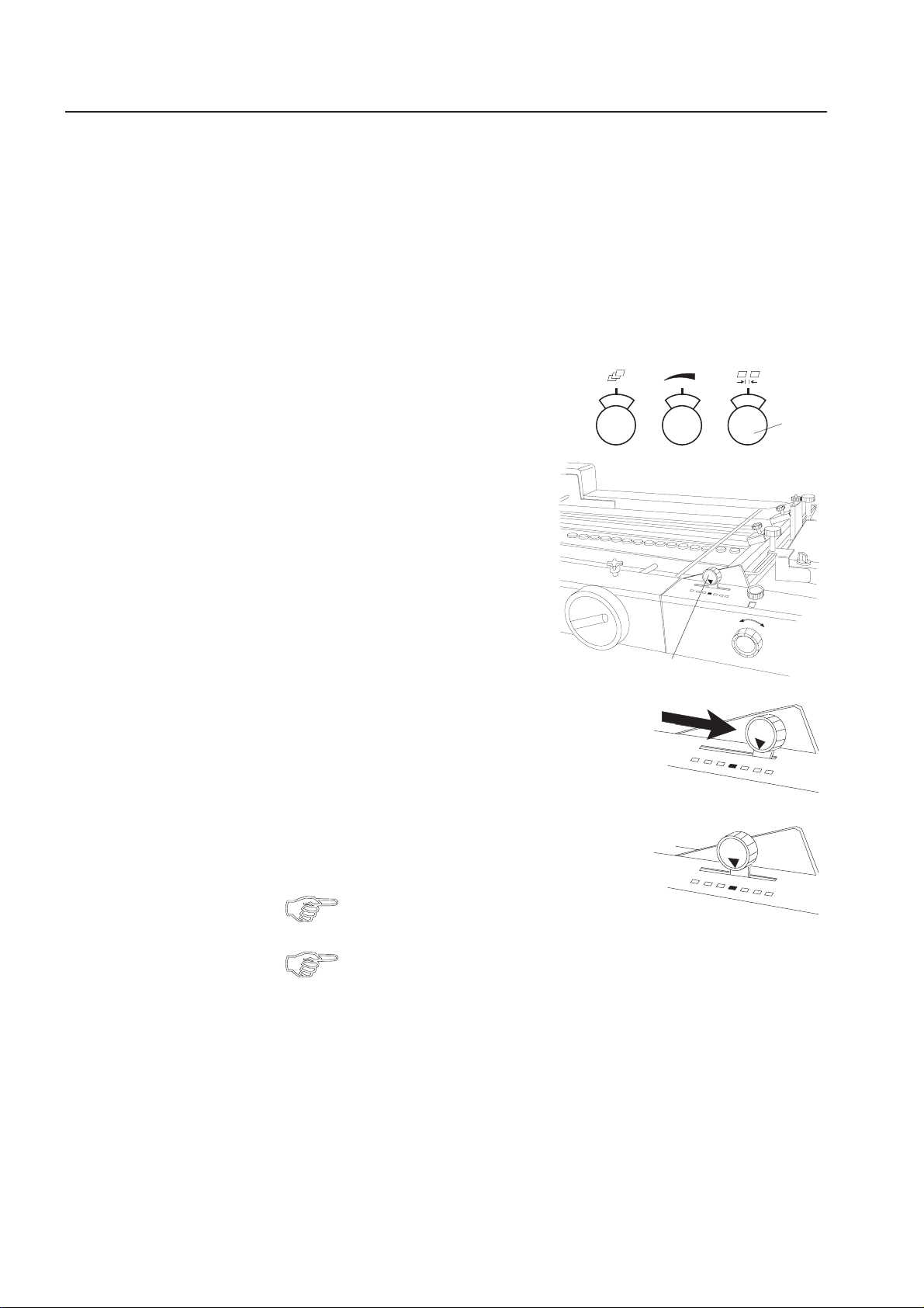
For normal folds the sheet gap should be set only via the potentiometer (1) on
the operator panel.
555
However, if small formats with a length
below8" aretobefolded,thesheet
gap can also be adjusted by means of
a lever (2).
The adjustment changes the speed of the
suction drum, i.e. different speeds of
feeder and fold rollers result in different
sheet gaps.
A smaller sheet gap increases the speed
of the folder, independent of the cycle
frequency.
2
1
Lever in right position:
Adjustmentofsmallformatsbelowalengthof8".
Lever in center position:
Setting for all "normal" folds.
The adjustment can be made with the machine
running.
To increase the sheet gap, always use the potentiometer (1) on the
operator panel, do not use the lever.
18
Page 19
Operator's Manual 2200 Series Flat Pile Feeder
9.FLATPILEFEEDERFD 2250
Principle of
Operation
Description
Theflatpilefeederwithrearedgeseparatorissuitableforseparatingdifferent
kinds of paper, uncoated as well as coated, freshly printed or thin paper.
Sheet separation is done by vacuum and air from the top of the paper stack.
Air blowers separate the top sheets at the rear edge of the stack.
Sheetseparatorslifttheuppermostsheetbyapprox. 3/4".
This opens the rear air nozzles and an uninterrupted stream of air is blown
under the separated sheet.
The suction drum at the front edge of the stack grips the sheet and leads it
onto the register table.
3
Componentsandoperatingelements
oftheflatpilefeeder:
1 Pile table
2 Stacking stops
3 Carrier arm for rear edge separator
4 Rear edge separator
5 Operator panel
6 Valves for regulating the air flow
7 Sheet separator height adjustment
8 Knurled knob for rear edge separator
9 Knurled knob for stripper springs
10 Rear separator nozzles
11 Front separator nozzles
12 Hold-down rods
13 2 sucker cups
14 Suction drum with suction segment
15 Lever for adjustment of suction segment
16 Rear edge separator lock lever
5
2
4
1
12
13
67
11
10
16
14
8
9
15
19
Page 20
Operator's Manual 2200 Series Flat Pile Feeder
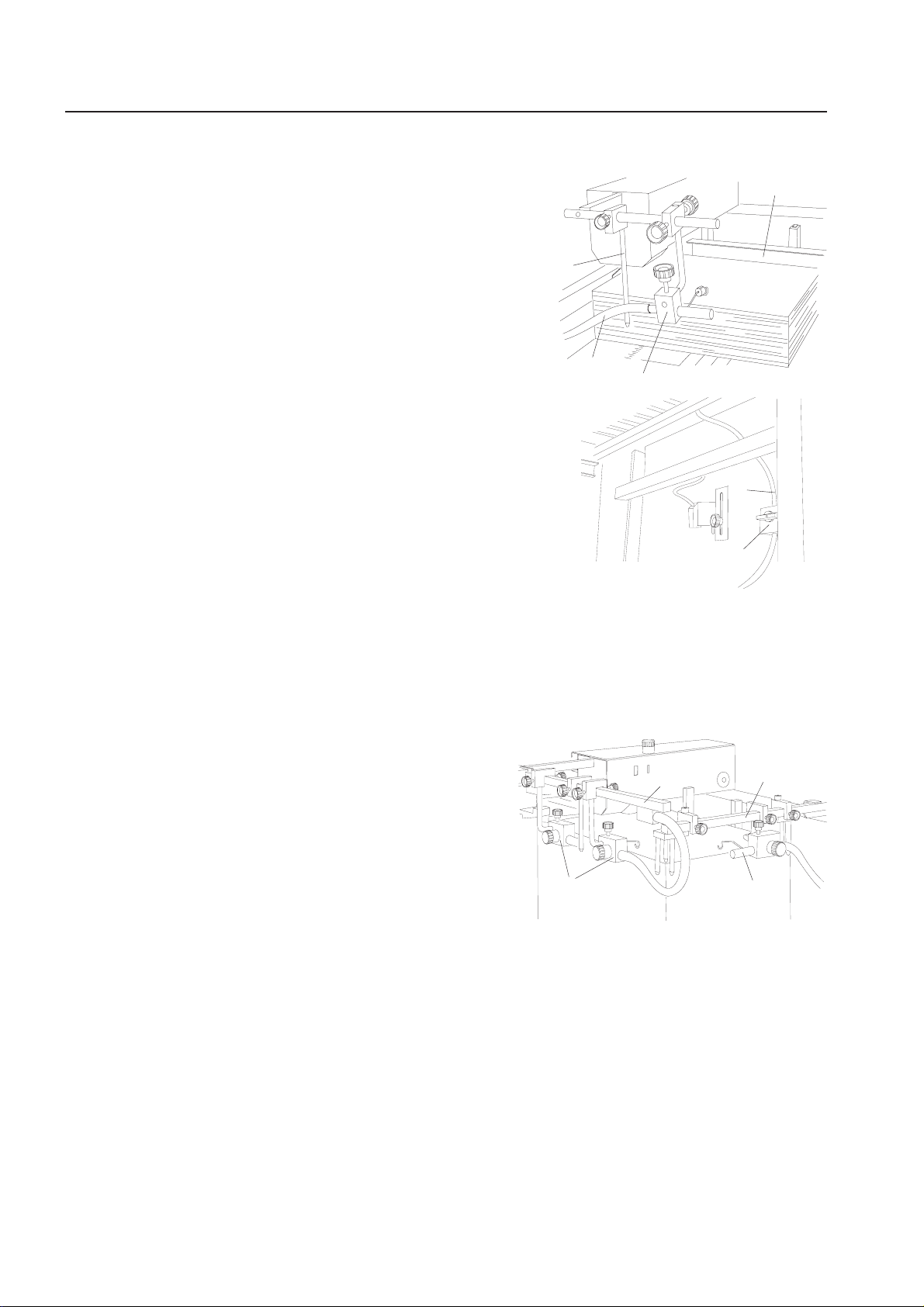
Setting the Format
Loading the Pile
Table
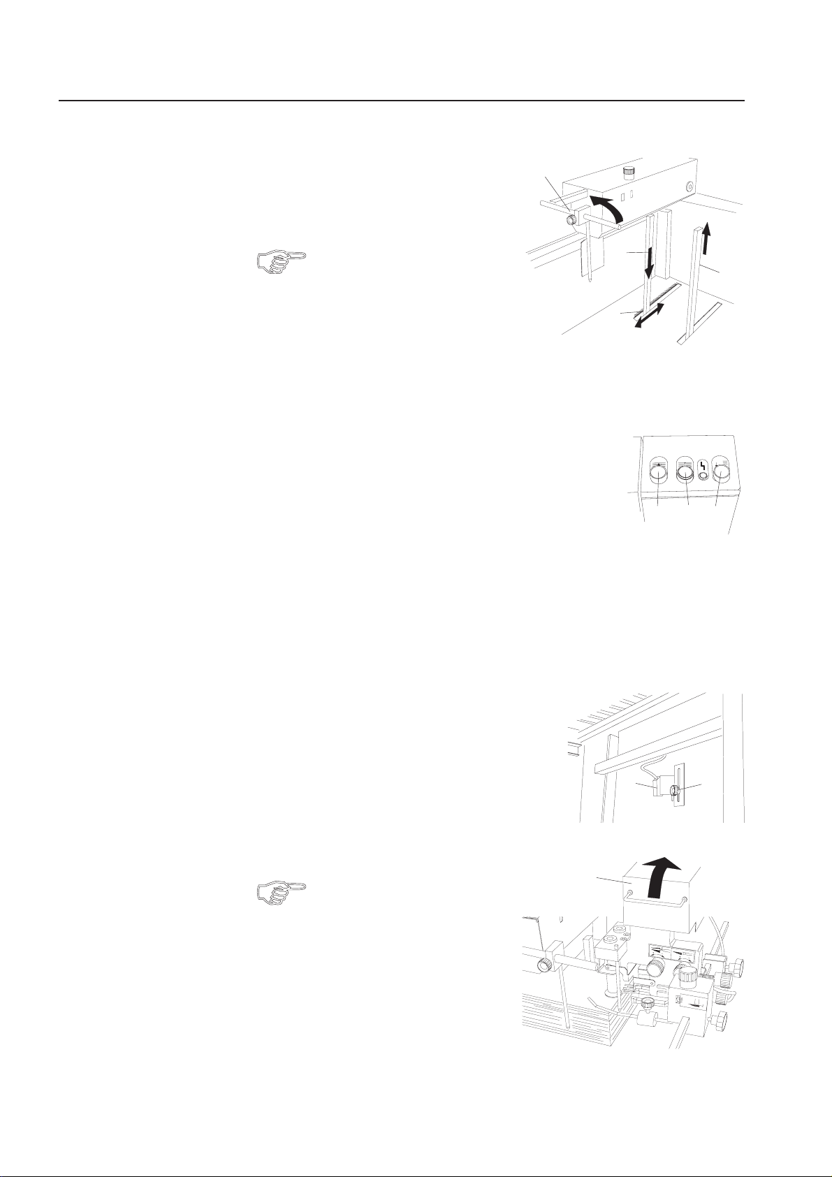
• Tilt up the front stop (1).
• Push down the rear stop (2) and slide
it to half the sheet width with the help
of the scale (3).
The second rear stop (4) can be pulled
out. This is necessary, if, for instance,
the rear edge separator is in this
position when feeding smaller
paper sizes.
• Turn on the main switch at the folder.
• Lower the pile table.
The operator panel of the flat pile feeder has three push-buttons
for lowering and raising the pile table.
Button (5): Pile table up:
The pile table moves up automatically to the
correct position.
Button (6): Pile table down:
The pile table moves down, but only as long as the push-button is pressed.
1
2
4
3
567
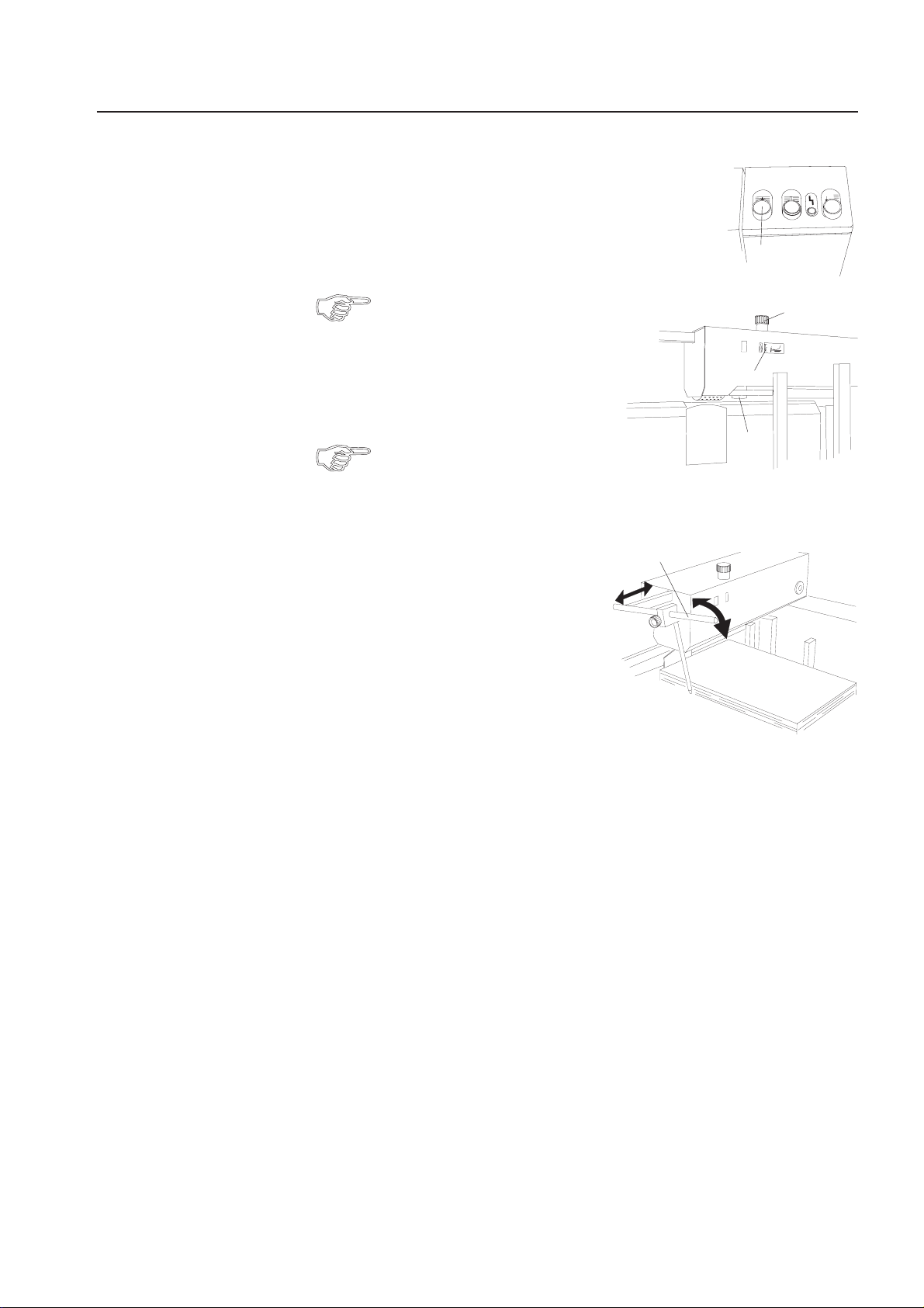
Button (7): Auto mode:
The feeder is designed in such a way that the pile table moves down
automatically for reloading. This ensures that the loading height is
always in an ergonomically favorable position.
The distance that the pile table moves down
corresponds to the height of the paper stack
that is being replenished.
The height adjustment is controlled by a
photodetector (8). The photodetector can
be adjusted by loosening a knob (9), thus
making it possible to adapt the stack
height to suit the operator.
• Tilt up the rear edge separator (10).
• Load paper on the pile table.
Use the automatic stacking
mechanism. Push button (7)
after each reloading process.
This will lower the table
automatically.
10
8
9
20
Page 21
Operator's Manual 2200 Series Flat Pile Feeder
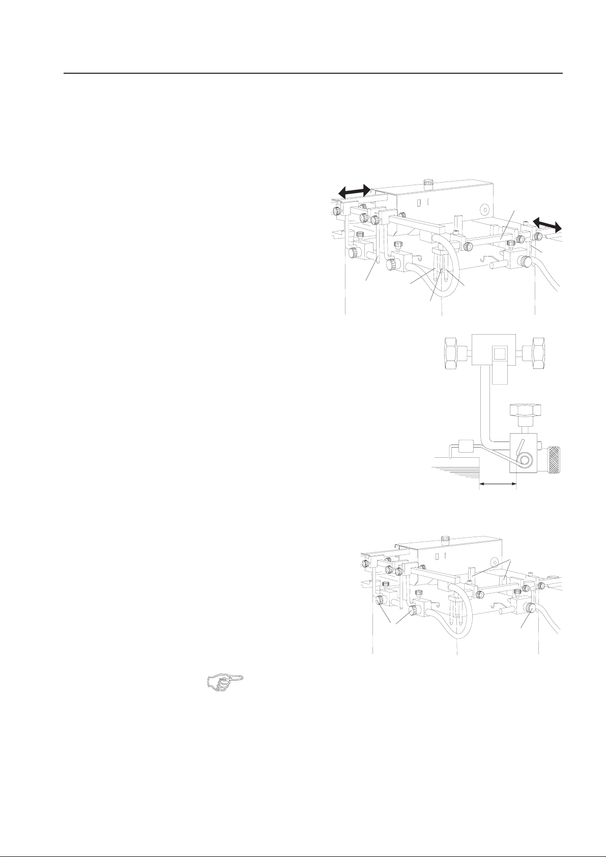
Moving the Paper
Stack to Work
Position
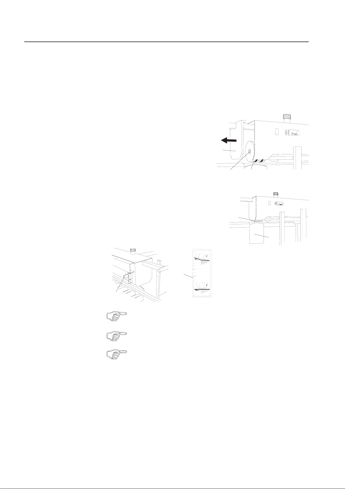
When the pile table is loaded, the paper stack must be brought
to the work position.
• Push button (1).
The stack moves automatically to the correct position,
controlled by the stack sensor switch (2).
The stack height switch is a capacitive sensor that reacts to the density of
the paper stack. For this reason the
gap between stack and suction drum
can vary when the paper stack has
reached the work position depending
on the type of paper used.
The gap between stack and suction drum
should be 8 mm.
• Set the gap to 8 mm by turning the setting screw (3).
A scale (4) facilitates this setting.
5
• Lower the front stop (5) and slide
it against the paper stack.
1
3
4
2
Air and Vacuum
Turn on the pump at the operator panel before setting air and vacuum.
The correct setting for air and vacuum can only be determined by running
a few sample sheets after all adjustments have been completed.
21
Page 22
Operator's Manual 2200 Series Flat Pile Feeder
Exchanging the
Suction Drum
Adjusting the
Suction Segment
The suction drum (1) is equipped with two PUR-rings for reliable sheet detachment.
If marks occur on sensitive or freshly printed paper, a different suction drum (accessory) can be used. This suction drum has a PUR-coating over the entire surface and
consequently a higher coefficient of friction.
For installation of this suction drum proceed as follows:
• Pull off the cover (2).
• Loosen the screw (3) and remove the
suction drum.
• Install the PUR suction drum.
• Tighten the screw (3).
• Replace the cover (2).
The suction drum (4) separates the leading edge of
the sheets from the stack. For this purpose there is a
suction segment inside the suction drum.
The suction angle can be changed by adjusting the
lever (5) to adapt suction point and suction area to
different types of paper.
A scale (6) facilitates the adjustment.
2
3
1
4
7
6
5
In most cases an adjustment is only necessary for light paper stock resp.
paper with a downward curl.
Fine adjustment is only possible with the machine running.
In connection with the adjustment of the suction segment, the height
of the separator plate (7) can also be varied.
0
22
Page 23
Operator's Manual 2200 Series Flat Pile Feeder
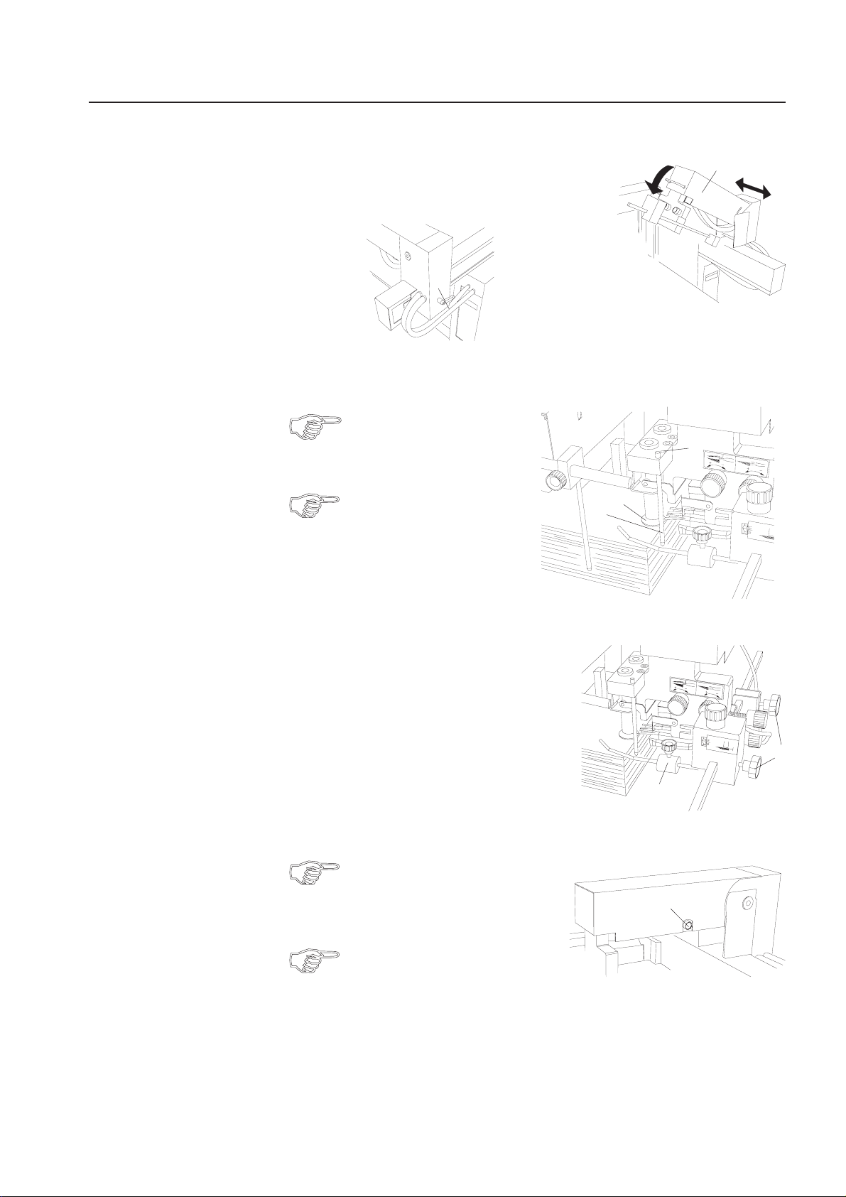
Setting the Rear
Edge Separator
• Lower the rear edge separator (1).
• Loosen the lock lever (2).
2
• Displace the rear edge separator in such a way that the stop rods (3) touch
the rear edge of the paper stack.
The edges of the sucker cups (4)
should be placed approx. 3-4 mm
from the rear edge of the paper
stack.
For light paper stock it is recommended to place the
suckers even closer to the
rear edge of the stack.
This is achieved by moving
the stop rods (3) to the next
set of holes (5).
4
3
1
5
• Tighten the separating head by turning the lock lever (2) clockwise.
• Slide the left and right hold-down rods (6)
towards the outer edge of the paper stack
(approx. 1 cm inside the edge).
• Adjusting the pressure of the hold-down
rods:
Heavy paper grades: Slide the weight (7) up.
Light paper grades: Slide the weight down.
7
• Check whether the automatic height setting mechanism is switched on.
The automatic height setting mechanism can be switched on and off by
pushing button (8). The illuminated
button shows that it is active.
For smaller paper sizes or flat sheets
the automatic height adjustment is
often not needed and can therefore
be switched off.
8
6
23
Page 24

Operator's Manual 2200 Series Flat Pile Feeder
Adjusting the
Stripper Springs
• Adjust the automatic height setting as follows:
The left hold-down bracket (1) also serves as
a height sensor controlling the height adjustment of the rear edge separator.
As a result, the gap between the suckers and
paper stack remains always the same although
sheets are pulled off continuously.
The basic position can be changed by means
of a knob (2).
A scale (3) facilitates the adjustment.
Increasing the gap: Move indicator to the plus-range "+".
Reducing the gap: Move indicator to the minus-range "-".
Basic setting: Sucker cups should be 1-2 mm above the paper stack
(with air turned off).
The stripper springs (4) should reach about
2 mm into the stack to prevent double sheets.
The position of the springs can be adjusted
by means of a thumb screw (5).
- Turn the thumb screw counter-clockwise:
Springs move away from the stack.
- Turn the thumb screw clockwise:
Springs move into the stack.
1
4
2
3
5
Making the Sucker
Cups Inoperative
If double sheets occur, the stripper fingers must be adjusted in such a way
that they reach further into the stack.
For short formats it is often advantageous
to work without rear edge separators.
In this case the sucker cups can be made
inoperative.
• Move the sucker cups to the top position (6).
• Push the lock lever (7) backwards. This will
lock the sucker cups in the top position.
• Switch off the automatic height setting
mechanism.
Now the air continuously separates the sheets
from the rear edge.
7
7
6
6
24
Page 25
Operator's Manual 2200 Series Flat Pile Feeder
Air
The air separates the rear edge of the paper stack by means of two rear separator
nozzles (1). The volume of the air can be adjusted by means of a valve (2).
The effect of the air can be influenced by changing the angle of the rear separator
nozzles. They can be pointed up- or downwards by turning a thumb screw (3).
- Air directed upwards:
Turn the screw counter-clockwise.
Too high: Double sheets may occur.
- Air directed downwards:
Turn the screw clockwise.
Too low: Sheets on top are not
fanned properly.
Air volume and angle are set correctly when the top 10 - 15 sheets separate
easily.
Use as little air as possible for proper function.
Another separator nozzle (4) is positioned between the rear separator nozzles.
It creates an air cushion under the separated sheet so that it attaches itself to the
suction drum. The air volume can be adjusted by means of the valve (5).
5
4
1
2
3
Most setting elements are equipped with scales. For repetitive feeding jobs
it is recommended to mark the settings at the scales.
The machine can thus be set-up more quickly.
Please note that the same result can only be reached if all conditions
are the same.
To support the air cushion, front blowers (6)
can be used.
They blow air under the leading edge of the
sheets so that the sheets cling more easily
to the suction drum.
The air volume can be controlled by means
of a valve (7), which can be closed completely by turning it clockwise.
6
7
25
Page 26
Operator's Manual 2200 Series Flat Pile Feeder
AdditionalBlower
Side Blowers
Anadditionalsingleblower(1)
stabilizes the air cushion near the leading
edge of the floating sheet. This is especially useful for long and narrow sheets.
The single blower (1) is positioned next
to the front stop (2), while the stop plate
(3) which comes with each single blower
is pushed onto the rear paper stops.
When the single blower is used, the front
blowers must be made inoperative.
For this purpose detach the hose (4) for
the front blowers from the valve (5) and
connect the air hose (6) of the individual
blower in its place.
The feeder can also be equipped with side blowers in the place of the rear edge
separator (see separate mounting instructions).
By supplying air to the side and rear edge of the stack, the topmost sheets are detached
so that separation through the suction drum is possible. Contrary to operation with the
rear edge separator, the topmost sheet is not lifted.
2
6
1
3
4
5
The air nozzles (7) are attached
to cross-bars at the side (8) and
the rear (9) of the paper stack.
For replenishing paper, the two
cross-bars can be raised to
provide access to the pile table.
After the replenishing process
the bars are returned to the
working position.
8
7
9
7
26
Page 27
Operator's Manual 2200 Series Flat Pile Feeder
Format setting:
• Move the rear cross-bar (1) (secured with a clamp lever) in such a way that the
sheet stop rods (2) are placed against the left- and right-hand side edge as well
as against the rear edge of the stack.
The weight rods (3)
on the left- and righthand side must touch
the corners of the stack.
1
2
42
3
• Move the lateral cross-bar until the side stop
(4) touches the stack.
• Adjust the air nozzles in such a way that they
are approx. 1 to 2 cm away from the side resp. rear edge.
• Adjust the angle of the air flow by turning the
air nozzles so that about 10 sheets are
separated.
The amount of air can be fine-adjusted by means of valves (5).
2
1-2 cm
6
5
The air cushion must not be so strong that the sheets under the suction drum
are compressed.
Place the stop plate on the rear stops (6) so that an air cushion is created.
5
27
Page 28

Operator's Manual 2200 Series Flat Pile Feeder
Aspecialsidestopattheright-hand side is part of the "side blower" kit.
This stop should beusedwhenthepapertendstodriftsideways.
The side stop is attached to the arm of the
suction wheel and can be moved sideways
so that it can be set to the format width.
28
Page 29
Operator's Manual 2200 Series Register Table
10.REGISTERTABLE
Setting the Format Flat Pile Feeder
Setting the Format AirFeeder
Register rail, ball cage and transport belt form one single
unit and are adjusted together.
Make sure that the feeder is set to the correct
format. Proceed as follows:
• Loosen the lock screw (1) of the register rail by
turning it counter-clockwise.
• Turn the handwheel (2) until the paper stop pin (3)
just touches the edge of the paper stack.
• Retighten the lock screw (1) by turning it clockwise.
• Set the rear paper support (11) to paper width,
using the scale and pointer.
• Distribute the hold-down bars (5) across the sheet
width. Place one hold-down bar in front of the
suction drum (6).
If the paper is less than 15 - 16 cm wide, the paper guide plate (4) must
be removed.
• Loosen the lock screw (1) by turning it counter-clockwise.
• Set the alignment rail to the paper size by turning the handwheel (2).
The scale at the fold roller infeed section (7) must show the same number as
the scale on the feeder (8).
1
2
4
3
5
6
11
7
8
10
• Tighten the lock screw (1) by turning it clockwise.
• Distribute the hold-down bars (9) across the width of the sheet.
The infeed angle can be changed by means of the knurled screw (10) and the
appropriate scale.
9
29
Page 30

Operator's Manual 2200 Series Register Table
Type of Balls
The number and type of balls in the ball cage
(1) depend on format and type of paper.
Always try to use as few balls as
possible. Balls not needed for a
particular job should be removed
to avoid wear of the transport belt.
1
It is recommended to use the following balls:
Papergradesbelow13 #:Plasticballs
Papergradesfrom13 - 33 #:Plasticballs,every6thshouldbeasteelball
Papergradesabove33 #:Mainlysteelballs
In the infeed section (the first 4 to 6 balls) it is recommended to always use one
or two steel balls.
For very light paper grades every second ball opening should be left free.
30
Page 31

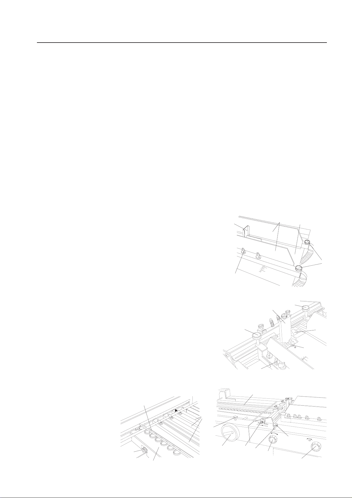
Operator's Manual 2200 Series Buckle Fold Units
11.BUCKLEFOLDUNITS
Thebucklefoldunitshaveaninfeedwidthof15" (when inline with the sealer paper
width is liminted to 11.5") and equippedwith4automaticfoldplates.
The automation of these fold plates comprises the automatic positioning of the
foldplatestopsandtheautomaticclosingofthedeflectors.
Itisnotnecessarytoremovethefoldplatesandtoinsertthedeflectorswhen
changing the fold.
Description
1 Noise covers
2 Fold roller adjustment knobs
3 Handwheel
4 Main switch
5 Operator panel
6 Transfer bridge
1
2
3
4
5
1
Fold Plate Positions
Inthefoldunitthere are four positions
forthefoldplates:
The fold plates are marked with a number.
Care has to be taken that the fold plates are
inserted in the correct positions, e.g. fold plate 1
in position 1, fold plate 2 in position 2, etc.
1
3
2
4
31
Page 32

Operator's Manual 2200 Series Buckle Fold Units
Installing the Fold
Plates
Connecting the Fold
Plates
Setting Elements of
the Fold Plates
The fold plates have one lock screw (1) each at the
left- and right-hand side.
Insert the fold plates in such a way that the lock screws
(1) fit in the recesses (2) in the frame of the fold unit.
Secure the fold plates by tightening the lock screws.
The electrical connection is done by means of
special 90° plugs (3).
They are inserted at the front of the fold plates
and secured by lightly tightening the threaded
sleeve.
Make sure that the main switch is OFF
before pulling or inserting the plug!
!
The number of the plug must agree with the number at the
front side of the plate!
!
• Knurled knob for angle corrections (4):
By turning the knurled knobs it is possible to make
angle corrections of the paper stop, for example, if
the paper is out-of-square.
2
2
1
3
4
Setting the Fold
Length
• Setting knob for adjusting the lower lip of the fold plates:
The lower lip can be adjusted by means of a setting knob in
order to increase or decrease the space for forming the buckle,
depending on paper thickness and paper stiffness.
A scale indicates the positioning of the lower lip.
Basic position: "0" is flush with the top of the knob (5).
Lower lip advanced: Small buckle space (6), setting knob "-"
Lower lip set back: Large buckle space (7), setting knob "+"
- Thin paper grades: Advance the lower lip, "-"
- Heavy paper grades: Set back the lower lip, "+"
• Allen screws for changing the gap between the fold
plate and the fold rollers:
For difficult-to-handle paper it is possible to set back
the complete fold plate by up to 4 mm.
For this two Allen screws (8) have to be loosened at
the left and right side of the fold plate.
A scale (9) facilitates precise setting.
Setting the fold length and closing the deflectors is controlled by the computer.
The respective commands are entered on the operator panel (see paragraph 16.)
5
6
-
7
9
-
-
0
+
8
32
Page 33

Operator's Manual 2200 Series Transfer Bridge
12.Transfer Bridge
Transfer Bridge
Folders with two fold units are always equipped with a transfer bridge (1).
This bridge ensures the accurate transfer of the sheet onto the roller table.
Two ball cages guide the sheets.
Proceed as follows when changing the format:
• Loosen the clamp screws (2) by turning
them counter-clockwise.
• Shift the ball cage in such a way that the balls run on a belt.
• Tighten the clamp screws by turning them clockwise.
• If necessary, the ball cages can also be moved in
or out (loosen Allen screws (3) on both sides).
The angle of the bridge is adjustable and can therefore
be adapted to the paper quality and the type of fold.
• Loosen the Allen screws (4) on both sides.
• Change the angle of the bridge.
• Tighten the Allen screws.
1
4
2
3
5
Ejector Rollers
Make sure that the belts do not drag on the roller table!
Set the adjusting brackets (5) on both sides of the bridge accordingly.
!
The ejector rollers on the delivery shafts must be set so that they are running on
top of each other (6).
An adjustment is only necessary when the sheets are no longer guided properly
after a change of format. To adjust:
• Turn the handwheel until the set screws of the
ejector rollers are visible (7).
•LoosentheAllenscrewswitha3-mmAllenkey.
• Shift the ejector rollers to the required position.
6
• Tighten the Allen screws.
7
33
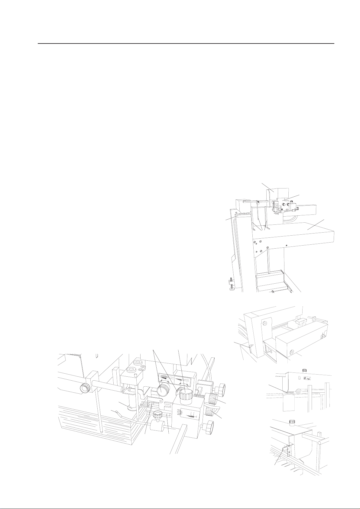
Page 34

Sealing Unit
Align the sealing unit with the transport
table and secure it in position with the
thumbscrews. The plexi saftey cover
must be closed or the machine won’t
nectors 2,3 and 9
Plexi saftey cover
3
Photo-eye
Fuse (located on the back side)
4
34
Page 35

Operator's Manual 2200 Series Stacker
14.STACKER
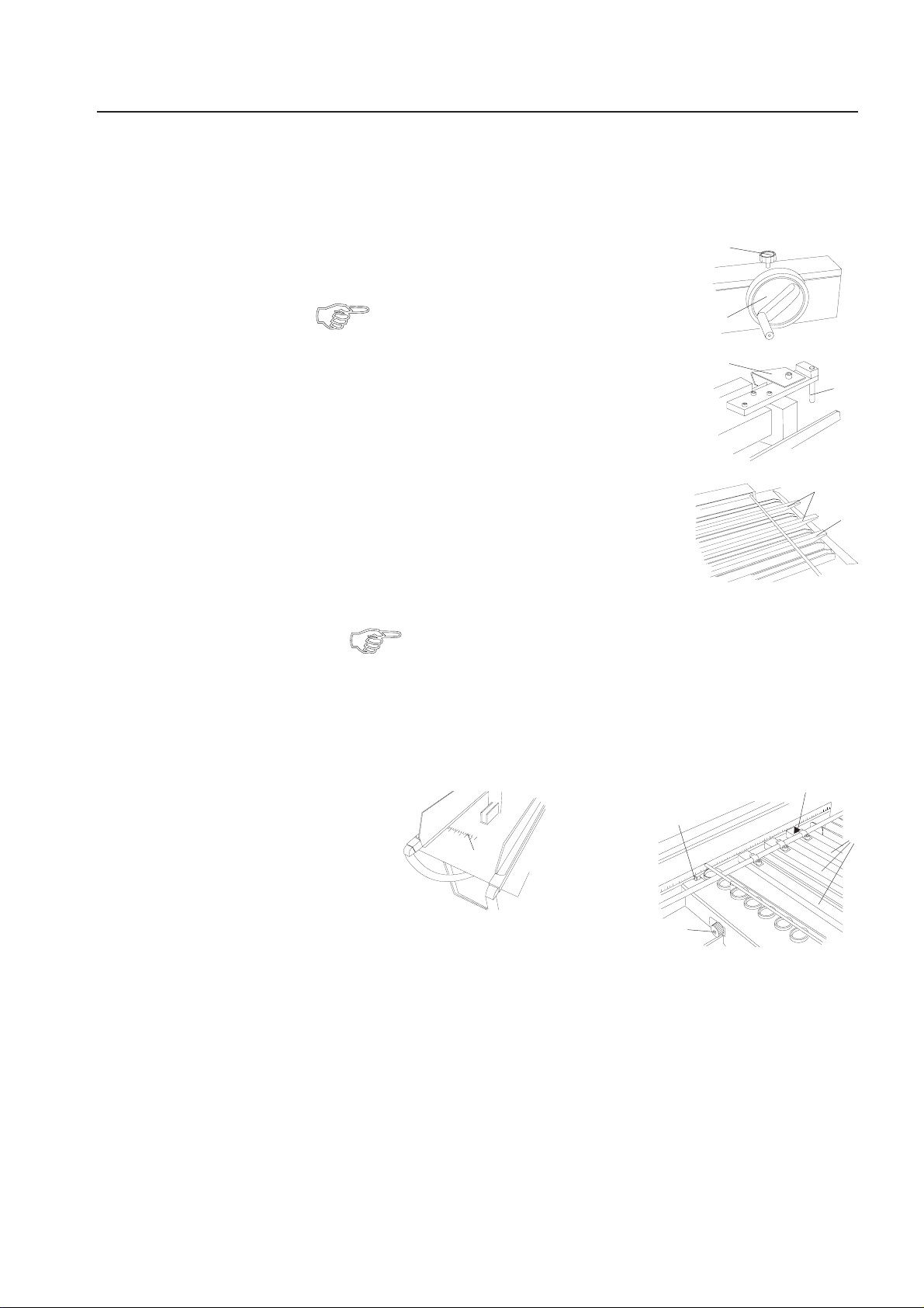
Stacker
Setting the Transfer
Height
Setting the Format
Thestacker is mobile.The heightisadjustable by means of a
gas-filledshock-absorber.
An additional control box (1) allows stopping and starting the machine (2) and
paper feed (3) to facilitate setting the hold-down rollers.
7
• Loosen the lock screw (4) by
turning it counter-clockwise.
• Lift or lower the delivery table.
• Tighten the lock screw (4) by
turning it clockwise.
3
2
The hold-down rollers (5) are needed for
achieving a clean fanned delivery.
They prevent the folded sheets from
opening up on the delivery belt.
The hold-down rollers are adjustable
in two direction (6, 7).
When moving them sideways make sure that the rollers always run
on a delivery belt.
The distance between delivery shafts (8) and hold-down
roller (9) should correspond to the sheet length of the
folded sheet (10). To adjust, proceed as follows:
9
5
6
1
4
8
Electrical
Connection
• Turn the setting wheel (11) to the left or to the right
and shift the hold-down rollers to their new position.
Pushing the button (12) will move the delivery belts for
easy removal of sample sheets.
The pressure of the hold-down rollers can be changed
by turning the knurled screws (13).
Chooselesspressureforthinpaperbelow20 #
andmorepressureforpaperabove39 #.
The electrical connection of the delivery section is
made by plugging the connecting cable into the
socket (14) in the last fold unit.
When making or breaking any electrical
connection, always first turn off the main
!
switch or the safety switch of the folder.
Non-compliance may cause damage to
electronic components!
1
13
12
11
14
35
Page 36

Operator's Manual 2200 Series Automatic Setting
15.AUTOMATICSETTING
OperatorPanel
Description
The 2200 Series machines areequippedwithacentraloperator panel.
Itisherewherethecommunicationbetweenoperatorandmachinetakesplace
and where all the important settings and monitoring functions are carried out.
The swing-around operator panel can be moved
to the position which is most convenient for the
operator.
Setting elements and keys with the following functions:
12 3 4 5 6 7
Computer Automated System
555
CAS
F7
F6
F8
F11 F12
7
F9 F10
?
89
F1 F2 F3 F4 F5
C
9101112 13 14 15
1 Sheet gap in delivery section
2 Fold speed
3 Sheet gap on the register table
4 Display
5 Display of menu FOLD LENGTH
6 Display of menu ROLLER GAP
7 Measuring system / language
8 Keys for numerical input
9 Pump
10 Fold roller drive
11 Sheet gap
12 Return to BASIC menu
13 Function keys for displaying different menus
14 Confirmation of a value entered
15 Information for service technician
456
0123
8
36
Page 37

Operator's Manual 2200 Series Automatic Setting
Description of the
Display
The operator panel contains an LC-display.
After switching on the machine, the following message appears:
TOTAL: JOB NO:
00000000
OUTPUT:
00000
REMAINDER:
/h
0000
MONITORING:
DOUBLES:
TRANSPORT:
OFF
OFF
0000
MONITORING SAVING
COUNTER SET-UP JOB
F1 F5F2 F3 F4
This display gives an overall view of the most important data.
For this reason the BASIC menu should always be called up when running the folder.
The displays for TOTAL, OUTPUT, REMAINDER, DOUBLES, TRANS-
PORT always refer to the actual folding job.
The JOB NO may refer to the actual folding job, but this is not necessarily
the case.
When calling up the menu, the job number which was saved last or which
was recalled from the memory is automatically displayed.
A job which was not saved cannot have an identification number and is
therefore not displayed.
The following main menus can be chosen from the BASIC menu:
• COUNTER Setting of total and batch counting
• MONITORING Activation of double sheet detection and paper travel control
• SET-UP Automatic setting of fold lengths / Input of setting infor-
mations
• SAVING Saving of repetitive jobs
• JOB Actual folding job
A number of function keys (F1 to F7) with arrows pointing to the headlines of
the main menu are grouped around the display.
By pressing one of these keys, the selected main menu is displayed.
37
Page 38

Operator's Manual 2200 Series Automatic Setting
Each menu is divided into a light and a dark section.
Actual data is shown in the light section (1).
In the dark section (2), additional menus are displayed, which can also be called up
by pressing the function keys.
The last line in the light section is the "command line" (3) and serves as an operator
guide.
This "command line" is very important because it indicates which command must be
carried out next.
JOB SAVED:
1
FORMAT(in):
FOLD
IN FOLD UNIT:
3
2
The keys on the operator panel are secured against incorrect operation, which means
that malfunctions caused by unacceptable inputs or accidental pressing of keys will
be prevented. Keys that are not used are automatically made inactive.
To help you familiarize yourself with this new system, the commands of the most
important settings are explained step by step on the following pages.
The sequence of the commands is shown by numbered input lines (4) so you will
quickly understand the logic of the procedure.
Examples:
AFTER ENTERING NUMBER:
--------- SELECT ---------------JOB CONTENTS
LENGTH:WIDTH:
5.5 5.5
1: 2:
9999
FOLD
SET-UP
38
1. Press key C The BASIC menu is displayed.
4
2. Press key F3 The SET-UP menu is displayed.
By following the sequence shown and observing the instructions, you will soon master
the operation of the machine and benefit from the advantages of the computer control.
If you get confused while entering commands, simply return to the BASIC
menu by pressing key C and start again.
The following operating instructions are arranged in such a way that all main menus
are described, starting with COUNTER and finishing with JOB.
Page 39

Operator's Manual 2200 Series Automatic Setting
Main Menu COUNTER
Setting the Counter - Main Menu COUNTER
1. Press key C The BASIC menu is displayed.
TOTAL: JOB NO:
00000000
0000
OUTPUT:
00000
REMAINDER:
/h
MONITORING:
DOUBLES:
TRANSPORT:
OFF
OFF
0000
MONITORING SAVING
COUNTER SET-UP JOB
F1 F5F2 F3 F4
2. Press key F1 The COUNTER menu is displayed.
COUNTER
The figures in the
display refer to a
previous folding job.
BATCH:
INTERVAL:
TOTAL:
AFTER ENTERING NUMBER:
0111
11
00000111
Clearing the Total
Counter
CLEAR
SELECT
F1 F2 F3 F4
3. Press key F4 The total counter is cleared.
COUNTER
BATCH:
INTERVAL:
TOTAL:
AFTER ENTERING NUMBER:
SELECT
F1 F2 F3 F4
00000000
TOTAL
0111
11
CLEAR
TOTAL
39
Page 40

Operator's Manual 2200 Series Automatic Setting
Main Menu COUNTER
Setting the Batch
Counter
The dark background of the line BATCH means that the preselected number of
sheets per batch can be entered.
The batch counter is used to mark a pre-selected number of sheets (batch) in
such a way that it can be separated from the next batch.
This makes it easy to remove the individual batches from the delivery table.
The following data must be entered for batch counting:
• the desired number of sheet per batch (preselection)
• the length of the gap (interval) between batches
Example: Batches of 50 sheets.
4. Enter the number of sheets (e.g 50) The new BATCH is displayed.
COUNTER
BATCH:
INTERVAL:
TOTAL:
AFTER ENTERING NUMBER:
0050
11
00000000
CLEAR
SELECT
F1 F2 F3 F4
5. Press key The new batch is saved.
COUNTER
BATCH:
INTERVAL:
TOTAL:
AFTER ENTERING NUMBER:
SELECT
F1 F4F2 F3
00000000
TOTAL
0050
11
CLEAR
TOTAL
40
The dark background of the line INTERVAL means that the interval needed for
batch counting can be entered.
Page 41

Operator's Manual 2200 Series Automatic Setting
Main Menu COUNTER
Example: The gap between batches (interval) in the delivery section should be as long
as it takes to feed 4 sheets.
6. Enter the interval (e.g. 4) The new INTERVAL is displayed.
COUNTER
BATCH:
INTERVAL:
TOTAL:
AFTER ENTERING NUMBER:
SELECT
F1 F4F2 F3
7. Press key The new interval is saved.
COUNTER
BATCH:
INTERVAL:
TOTAL:
0050
04
00000000
CLEAR
TOTAL
0050
04
00000000
AFTER ENTERING NUMBER:
CLEAR
SELECT
F1 F2 F3 F4
The dark background moves again back to the BATCH line. By pressing key F1 it is
possible to alternate between BATCH and INTERVAL lines.
When batch counting is not used, enter "0" for BATCH or INTERVAL.
8. Press key C Back to BASIC menu.
TOTAL
41
Page 42

Operator's Manual 2200 Series Automatic Setting
Main Menu MONITORING
Paper Transport Control, Double Sheet Detection - Main Menu MONITORING
1. Press key C The BASIC menu is displayed.
TOTAL: JOB NO:
00000000
0000
OUTPUT:
00000
REMAINDER:
/h
MONITORING:
DOUBLES:
TRANSPORT:
OFF
OFF
0000
MONITORING SAVING
COUNTER SET-UP JOB
F1 F5F2 F3 F4
2. Press key F2 The MONITORING menu is displayed.
MONITORING
DOUBLES: OFF
TRANSPORT: OFF
SWITCH ON /OFF
DOUBLES TRANSPORT
Paper Transport
Control
ON OFF ON OFF
F1 F5F2 F4
3. Press key F4 The paper transport control is active.
MONITORING
DOUBLES: OFF
TRANSPORT: ON
SWITCH ON /OFF
DOUBLES TRANSPORT
ON OFF ON OFF
F1 F5F2 F4
42
Page 43

Operator's Manual 2200 Series Automatic Setting
Main Menu MONITORING
Double Sheet
Detection
4. Press key F1
MEASURE PAPER THICKNESS
START TWO SHEETS
Prior to switching the machine on, it must be set-up and the feeder must
be loaded with paper.
5. Switch on pump and main motor. Press the sheet transport key (1x).
6. Press the sheet transport key (1x). The paper thickness is displayed.
MEASURE PAPER THICKNESS
PAPERTHICKNESS(in):
DOUBLE SHEET DETECTIONON
7. Switch off the main motor and the pump.
8. Press key C Back to BASIC menu.
0.10
If the double sheet detection or the paper transport control is to be deactivated,
the CONTROL menu must be called up by pushing key F2 in the BASIC
menu - then push key F2 or F5.
43
Page 44

Operator's Manual 2200 Series Automatic Setting
Main Menu SET-UP
Setting the Fold Length - Main Menu SET-UP
Theautomaticsettingofthe2200 Series makesitpossiblethatallstopsdriven by timing belts and servo motors - are set automatically to the position
calculated by the computer.
The fold plates which are not used for a particular folding job are automatically
closed by deflectors and always remain in the fold unit.
The fold plate stops can be set in three different ways:
1. Automatic setting of pre-programmed standard folds
2. Entering the fold lengths individually on the keyboard - Special folds
3. Calling up fold programs from the memory - Job saved
Standard Folds
For this type of setting, it is not necessary to make a sample fold by hand and to
measure it. Just enter the required type of fold.
The following standard folds are permanently programmed in the software:
Single fold
Z-fold
2x
Z-fold
4x
44
Letter
fold
Double parallel
fold
Open
gate fold
Page 45

Operator's Manual 2200 Series Automatic Setting
Main Menu SET-UP
Standard Folds
1. Press key C The BASIC menu is displayed.
TOTAL: JOB NO:
00000000
0000
OUTPUT:
00000
REMAINDER:
/h
MONITORING:
DOUBLES:
TRANSPORT:
ON
ON
0000
MONITORING SAVING
COUNTER SET-UP JOB
F1 F5F2 F3 F4
2. Press key F3 The SET-UP menu is displayed.
SET-UP
SELECT WITH FUNCTION KEYS
F7
F6
-------- FOLD ------------SPECIAL STANDARD
SUCTION LENGTH
JOB SAVED
ROLLER
GAP
DELIVERY
F1 F5F2
3. Press key F2 The STANDARD FOLDS menu is displayed.
STANDARD FOLDS
FOLD UNIT:
AFTER SELECTING FOLD:
FOLD UNIT FOLD SET-UP
F1 F5F3
Pressing key F3 several times will shift the cursor (dark rectangle) from
one symbol to the other.
1
F4
45
Page 46

Operator's Manual 2200 Series Automatic Setting
Main Menu SET-UP
Standard Folds
Settingexample:ADIN 11" x 17" sheetistobefoldedasfollows:
First fold unit: Z-fold Second fold unit: Letter fold
4. Press key F3 until the respective fold symbol for the first fold unit
(Z-fold) is marked by the cursor.
STANDARD FOLDS
FOLD UNIT:
AFTER SELECTING FOLD:
FOLD UNIT FOLD SET-UP
F1 F5F3
5. Press key The selected fold is confirmed.
FOLD UNIT:
The format length
of a previous job is
shown in the display.
FORMATLENGTH(in):
AFTER ENTERING NUMBER:
1
STANDARD FOLDS
1
11
46
FOLD UNIT FOLD SET-UP
F1 F5F3
6.Entertheformatlength(17)Thenewformatlengthisdisplayed.
STANDARD FOLDS
FOLD UNIT:
FORMATLENGTH(in):
AFTER ENTERING NUMBER:
FOLD UNIT FOLD SET-UP
F1 F5F3
If a format is entered that cannot be handled by the machine because it is too
small or too large, this is recognized by the computer and shown in the display.
1
17
Page 47

Operator's Manual 2200 Series Automatic Setting
Main Menu SET-UP
Standard Folds
7. Press key The new format length is saved.
STANDARD FOLDS
FOLD UNIT:
FORMATLENGTH(in):
SET-UP
OR CHOOSE FOLDUNIT
1
14
FOLD UNIT FOLD SET-UP
F1 F5F3
8. Press key F1 The second fold unit is selected.
STANDARD FOLDS
FOLD UNIT:
2
Since, in our example,
a letter fold is to be
made in the second
AFTER SELECTING FOLD:
fold unit, the cursor
must be shifted to
the respective fold
FOLD UNIT FOLD SET-UP
symbol.
F1 F5F3
9. Press key F3 repeatedly until the respective fold symbol for the second
fold unit (letter fold) is marked by the cursor.
STANDARD FOLDS
FOLD UNIT:
AFTER SELECTING FOLD:
2
FOLD UNIT FOLD SET-UP
F1 F5F3
47
Page 48

Operator's Manual 2200 Series Automatic Setting
Main Menu SET-UP
Standard Folds
10. Press key The new format length is saved.
STANDARD FOLDS
FOLD UNIT:
FORMATWIDTH(in):
The format width of
a previous job is
shown in the display.
11.Enterformatwidth(11)Thenewformatwidthisdisplayed.
AFTER ENTERING NUMBER:
FOLD UNIT FOLD SET-UP
F1 F5F3
FOLD UNIT:
FORMATWIDTH(in):
AFTER ENTERING NUMBER:
2
8.5
STANDARD FOLDS
2
11
If a format is entered that cannot be handled by the machine because it is too
small or too large, this is recognized by the computer and shown in the display.
12. Press key
FOLD UNIT FOLD SET-UP
F1 F5F3
STANDARD FOLDS
FOLD UNIT:
FORMATWIDTH(in):
SET-UP
OR CHOOSE FOLDUNIT
FOLD UNIT FOLD SET-UP
F1 F5F3
2
11
48
Page 49

Operator's Manual 2200 Series Automatic Setting
Main Menu SET-UP
Standard Folds
13. Press key F5 The stops are positioned automatically and the
fold plates not needed are closed by deflectors.
STANDARD FOLDS
FOLD UNIT:
FORMATWIDTH(in):
SETTING FOLD STYLE
2
11
FOLD UNIT FOLD SET-UP
F1 F5F3
The display SETTING FOLD STYLE is flashing until the setting process
is completed. Then the following message appears:
MEASURE PAPER THICKNESS
START TWO SHEETS
Prior to switching the machine on, it must be set up and the feeder must be
loaded with paper.
14. Switch on pump and main motor, press the sheet transport key (1x).
49
Page 50

Operator's Manual 2200 Series Automatic Setting
Main Menu SET-UP
Standard Folds
15. Press the sheet transport key (1x) The paper thickness is displayed.
MEASURE PAPER THICKNESS
PAPERTHICKNESS(in):
DOUBLE SHEET DETECTIONON
After a few seconds the display returns to the SET-UP menu.
SET-UP
SELECT WITH FUNCTION KEYS
SUCTION LENGTH
JOB SAVED
--------- FOLD ------------SPECIAL STANDARD
ROLLER
GAP
0.10
F7
F6
DELIVERY
F1 F5F2
F4
16. Switch off main motor and pump.
17. Press key C Back to BASIC menu.
50
Page 51

Operator's Manual 2200 Series Automatic Setting
Main Menu SET-UP
Special Folds
Special Folds
This kind of set-up resembles most the principle used in conventional folding machines because the fold length of each stop must be calculated or measured before setting.
The actual setting, however, is done at the operator panel.
1. Press key C The BASIC menu is displayed.
TOTAL: JOB NO:
00000000
OUTPUT:
00000
REMAINDER:
/h
0000
MONITORING:
DOUBLES:
TRANSPORT:
ON
ON
0000
MONITORING SAVING
COUNTER SET-UP JOB
F1 F5F2 F3 F4
To enter the measurements for the fold lengths, e.g. to set the fold plate stops,
the menu SET-UP must be called up via key F3.
2. Press key F3 The SET-UP menu is displayed.
SET-UP
SELECT WITH FUNCTION KEYS
SUCTION LENGTH
--------- FOLD ------------
SPECIAL STANDARD
F1 F5F2
JOB SAVED
ROLLER
GAP
F4
DELIVERY
F7
F6
51
Page 52

Operator's Manual 2200 Series Automatic Setting
Main Menu SET-UP
Special Folds
3. Press key F1 The SET-UP SPECIAL FOLD menu for fold unit 1
is displayed.
SET-UPSPECIALFOLD(in)
FOLD UNIT:
ACT: 3.3 NOM:
ENTER NOMINAL VALUES
FOLD UNIT
F1 F5F2 F3 F4
ThedisplayshowsACT(Actual)asthecurrentfoldlength(e.g.5.5)
and the matching fold symbol, e.g. , , ...
Example:AsheetinformatDIN8.5" x 14"
is to be folded.
Example: Eccentric Z-fold
Example Foldplate1: 5.25 in
(Z-fold)Foldplate2: 5.25 in
Foldplate 3: 0 in
Foldplate 4: 0 in
1
PLATE - + SET-UP
-PLATE:
5.25
5.25
1
14"
52
99
198
11"
4.Enterthefoldlengthforthefirstfoldplate Example:3.3
SET-UPSPECIALFOLD(in)
FOLD UNIT:
ACT:NOM:
AFTER ENTERING NUMBER:
FOLD UNIT
3.3 5.25
F1 F5F2 F3 F4
1
PLATE - + SET-UP
-PLATE:
1
Page 53

Operator's Manual 2200 Series Automatic Setting
Main Menu SET-UP
Special Folds
5. Press key The fold length is saved.
SET-UPSPECIALFOLD(in)
FOLD UNIT:
ACT:NOM:
ENTER NOMINAL VALUES
FOLD UNIT
6.PresskeyF2Foldplate2iscalledup.
SET-UPSPECIALFOLD(in)
FOLD UNIT:
AC
ENTER NOMINAL VALUES
FOLD UNIT
3.3 5.25
F1 F5F2 F3 F4
T: 3.4 NOM:
1
PLATE - + SET-UP
1
-PLATE:
-PLATE:
1
2
PLATE - + SET-UP
F1 F5F2 F3 F4
7.Enterfoldlengthforthesecondfoldplate Example:3.4
SET-UPSPECIALFOLD(in)
FOLD UNIT:
ACT:NOM:
AFTER ENTERING NUMBER:
FOLD UNIT
3.4 5.25
F1 F5F2 F3 F4
1
PLATE - + SET-UP
-PLATE:
2
53
Page 54

Operator's Manual 2200 Series Automatic Setting
Main Menu SET-UP
Special Folds
8. Press key The fold length is saved.
SET-UPSPECIALFOLD(in)
FOLD UNIT:
ACT:NOM:
ENTER NOMINAL VALUES
FOLD UNIT
9. Press key F2 Fold plate 3 is called up.
SET-UPSPECIALFOLD(in)
FOLD UNIT:
ACT: NOM:
ENTER NOMINAL VALUES
FOLD UNIT
3.4 5.25
F1 F5F2 F3 F4
5.5
1
PLATE - + SET-UP
1
-PLATE:
-PLATE:
2
3
PLATE - + SET-UP
F1 F5F2 F3 F4
10.Enterfoldlengthforthethirdfoldplate Example:0
SET-UPSPECIALFOLD(in)
FOLD UNIT:
ACT: NOM:
AFTER ENTERING NUMBER:
FOLD UNIT
5.5 00
F1 F5F2 F3 F4
1
PLATE - + SET-UP
PLATE:
3
54
Page 55

Operator's Manual 2200 Series Automatic Setting
Main Menu SET-UP
Special Folds
11. Press key The fold length is saved.
SET-UPSPECIALFOLD(in)
FOLD UNIT:
ACT: NOM:
ENTER NOMINAL VALUES
FOLD UNIT
12. Press key F2 Fold plate 4 is called up.
SET-UPSPECIALFOLD(in)
FOLD UNIT:
ACT: NOM:
ENTER NOMINAL VALUES
5.5
F1 F5F2 F3 F4
1
00
PLATE - + SET-UP
1
5.5
PLATE:
-PLATE:
3
4
FOLD UNIT
PLATE - + SET-UP
F1 F5F2 F3 F4
13.Enterfoldlengthforthefourthfoldplate Example:0
SET-UPSPECIALFOLD(in)
FOLD UNIT:
ACT: NOM:
AFTER ENTERING NUMBER:
FOLD UNIT
5.5
F1 F5F2 F3 F4
1
00
PLATE - + SET-UP
-PLATE:
4
55
Page 56

Operator's Manual 2200 Series Automatic Setting
Main Menu SET-UP
Special Folds
14. Press key The fold length is saved.
SET-UPSPECIALFOLD(in)
FOLD UNIT:
ACT NOM:
ENTER NOMINAL VALUES
FOLD UNIT
Now the fold lengths for all 4 fold plates of the first fold unit are entered.
5.5 00
F1 F5F2 F3 F4
1
PLATE - + SET-UP
-PLATE:
4
56
Page 57

Operator'sManual 2200 Series
26. Press key The fold length is saved.
SET-UPSPECIALFOLD(in)
AutomaticSetting
Main Menu SET-UP
Special Folds
When all fold lengths
have been entered,
the next step is the
command for automatic setting of the
stops.
27. Press key F5
FOLD UNIT:
ACT:NOM:
ENTER NOMINAL VALUES
FOLD UNIT
SET-UPSPECIALFOLD(in)
FOLD UNIT:
ACT: NOM:
SETTING FOLD STYLE
5.5 000
F1 F5F2 F3 F4
5.5 000
2
PLATE - + SET-UP
2
PLATE:
PLATE:
4
4
FOLD UNIT
PLATE - + SET-UP
F1
The display SETTING FOLD STYLE is flashing until the setting is
completed. Then the following display appears:
MEASURE PAPER THICKNESS
START TWO SHEETS
Prior to switching the machine on, it must be set up and the feeder must
be loaded with paper.
F5F2 F3 F4
57
Page 58

Operator'sManual 2200 Series
28. Switch on pump and main motor. Press the sheet transport key (1x).
29. Press the sheet transport key (1x) The paper thickness is displayed.
Main Menu SET-UP
MEASURE PAPER THICKNESS
AutomaticSetting
Special Folds
PAPERTHICKNESS(in):
DOUBLE SHEET DETECTIONON
0.10
After a few seconds the display returns to the SET-UP menu.
SET-UP
SELECT WITH FUNCTION KEYS
SUCTION LENGTH
JOB SAVED
-------- FOLD -------------ROLLER
SPECIAL STANDARD
GAP
F7
F6
DELIVERY
58
F1 F5F2
F4
30. Switch off the main motor and the pump.
31. Press key C Back to BASIC menu.
Page 59

Operator'sManual 2200 Series
AutomaticSetting
Main Menu SET-UP
Job Saved
Job Saved
Entering the
Memory/Job
Number
A job can be recalled from memory only when the identification number (memory- or
job number) is known.
If the number is unknown, it is possible to display the contents of the memory and thus
find the number.
1. Press key C The BASIC menu is displayed.
TOTAL: JOB NO:
00000000
OUTPUT:
00000
REMAINDER:
/h
0000
MONITORING:
DOUBLES:
TRANSPORT:
ON
ON
0000
MONITORING SAVING
COUNTER SET-UP JOB
F1 F5F2 F3 F4
In order to set up a job from the memory, the SET-UP menu must be called up by
pressing key F3.
2. Press key F3 The SET-UP menu is displayed.
SET-UP
SELECT WITH FUNCTION KEYS
SUCTION LENGTH
JOB SAVED
--------- FOLD ------------
SPECIAL STANDARD
F1 F5F2
ROLLER
GAP
F4
DELIVERY
F7
F6
59
Page 60

Operator'sManual 2200 Series
3. Press key F6 The JOB SAVED menu is displayed.
AutomaticSetting
Main Menu SET-UP
Job Saved
JOB SAVED:
FORMAT(
in):LENGTH:WIDTH:
5.5
FOLD
IN FOLD UNIT
AFTERENTERING VALUE:
------------JOB------------------- FOLD
- + CONTENTS
F1F5F2 F3 F4
The display shows the number of the job which was last saved or recalled from the
memory. Select the job by using the F1 or F2 with the number key pad.
4. Enter the job number Example: 9999
1: 2:
1111
5.5
SET-UP
JOB SAVED:
FORMAT(in):LENGTH:WIDTH:
5.5
FOLD
IN FOLD UNIT
AFTERENTERING VALUE:
---------------JOB ---------------- FOLD
- + CONTENTS
F1F5F2 F3 F4
1: 2:
9999
5.5
SET-UP
60
Page 61

Operator'sManual 2200 Series
5. Press key The format and fold are displayed.
AutomaticSetting
Main Menu SET-UP
Job Saved
JOB SAVED:
FORMAT(in):LENGTH:WIDTH:
17
FOLD
IN FOLD UNIT
-------------JOB ------------------ FOLD
- + CONTENTS
F1F5F2 F3 F4
The next input depends on what values are to be taken over from memory:
•FoldlengthsonlycontinuewithkeyF5
This key is pressed if the new job uses the same paper size and fold, but a
different paper weight.
• Fold lengths, suction length as well as setting values for fanned delivery, fold
speed, fold roller gap and sheet gap continue with key F3
This key is pressed if the new job uses the same paper size, fold and the same
paper weight.
1: 2:
9999
11
SET-UP
The following example assumes that the new job uses the same paper weight and that
all values have to be called up for that reason.
6. Press key F3 The CONTENTS menu is displayed.
JOB SAVED:
SHINGLING SPEED GAP
9999
07 08 06
MANUAL SETTING
-----------------JOB --------------- FOLD
SET-UP
- + CONTENTS
F1 F5F2 F3 F4
7. These figures must be entered manually by turning the knobs with
the corresponding controls.
786
Delivery Speed Sheet gap
61
Page 62

Operator'sManual 2200 Series
8. Press key F3 Display ROLLER GAP.
JOB SAVED:
ROLLERGAP(in)
AutomaticSetting
Main Menu SET-UP
Job Saved
FOLD UNIT: GAP:
NOM:
MANUAL SETTING
--------------- SELECT --------------+ - CONTENTS AUTO+
F1 F5F2 F3 F4
For correct setting of the fold rollers the ACT
(Actual) value must be changed to the NOM
(Nominal) value.
This is done by turning the setting knobs (1).
The displayed NOM corresponds to
the value that was set during the saving
process (individual corrections are
taken into account).
All setting knobs have numbers so that the display message can be related to a specific
fold roller.
0.10
1
ACT:
0.00
1/1
1
1
The NOM and ACT values of the individual fold rollers can be displayed by pressing
keys F1, F2 or F4.
Key F1 (+): Display of NOM and ACT value for the next roller
(for example, advance from roller 2 to 3)
Key F2 (-): Display of NOMand ACTvalue for the previous roller
(for example, return from roller 2 to 1)
Key F4 (AUTO+): Automatic advance of NOM and ACT to the fold roller,
for which NOM and ACT do not agree
Description of the display messages:
GAP 5/2
5 Roller 5
2 Setting knob
on far side
GAP 1/1
1 Roller 1
1 Setting knob on
operator side
62
Page 63

Operator'sManual 2200 Series
9. Turn setting knob 1 (operator side) on the first fold unit until ACT
shows the same value as NOM.
JOB SAVED:
ROLLERGAP(in)
AutomaticSetting
Main Menu SET-UP
Job Saved
FOLD UNIT: GAP:
NOM:
MANUAL SETTING =
------------- SELECT ----------------+ - CONTENTS AUTO+
F1 F5F2 F3 F4
When the values agree, the symbol "=" appears in the command line.
All rollers can be called up and set by pressing keys F1, F2 or F4.
When the rollers in the first and second fold unit are set, the fold plate stops can
be moved to their positions.
10. Press key F3
JOB SAVED:
FORMAT(in):LENGTH:WIDTH:
0.10
1
ACT:
0.10
1/1
9999
17 11
FOLD
IN FOLD UNIT
AFTERENTERING VALUE:
--------------JOB ----------------- FOLD
- + CONTENTS
F1F5F2 F3 F4
1: 2:
SET-UP
63
Page 64

Operator'sManual 2200 Series
11. Press key F4 The fold plate stops and deflectors are positioned.
AutomaticSetting
Main Menu SET-UP
Job Saved
JOB SAVED:
9999
FORMAT(in):LENGTH:WIDTH:
17 11
FOLD
IN FOLD UNIT
SETTING FOLD STYLE
--------------JOB---------------- FOLD
- + CONTENTS
F1 F5F2 F3 F4
The line SETTING FOLD STYLE is flashing during set-up.
When the set-up is completed, this is signalled by a change of display:
SELECT WITH FUNCTION KEYS
1: 2:
SET-UP
SET-UP
SUCTION LENGTH
F7
---------- FOLD ------------SPECIAL STANDARD
F1 F5F2
JOB SAVED
ROLLER
GAP
F4
DELIVERY
F6
12. Press key C Back to BASIC menu.
64
Page 65

Operator'sManual 2200 Series
AutomaticSetting
Main Menu SET-UP
Job Saved
Displaying the Contents of Memory
1. Press key C The BASIC menu is displayed.
TOTAL: JOB NO:
00000000
OUTPUT:
00000
REMAINDER:
/h
0000
MONITORING:
DOUBLES:
TRANSPORT:
ON
ON
0000
MONITORING SAVING
COUNTER SET-UP JOB
F1 F5F2 F3 F4
To recall a job from memory, the menu SET-UP must be called up by pressing key F3.
2. Press key F3 The SET-UP menu is displayed.
SELECT WITH FUNCTION KEYS
-------- FOLD --------------
SPECIAL STANDARD
F1 F5F2
SET-UP
SUCTION LENGTH
JOB SAVED
ROLLER
GAP
F4
F7
F6
DELIVERY
65
Page 66

Operator'sManual 2200 Series
3. Press key F6 The JOB SAVED menu is displayed.
AutomaticSetting
Main Menu SET-UP
Job Saved
4. Press key F1
By pressing key F1
(JOB) severaltimes,
the memory number,
the format and the
fold type of each
individual job are
displayed, in the
sequence in which
the jobs were saved.
JOB SAVED:
FORMAT(in):LENGTH:WIDTH:
1111
5.5 5.5
FOLD
IN FOLD UNIT
AFTERENTERINH VALUE:
-------------JOB----------------- FOLD
- + CONTENTS
F1 F2 F3F5
JOB SAVED:
FORMAT(in):LENGTH:WIDTH:
1:
SET-UP
3333
14 14
FOLD
IN FOLD UNIT
AFTERENTERING VALUE:
--------------JOB----------------- FOLD
- + CONTENTS
1:
SET-UP
F1 F2F3F5
Once the job is found, it can be set up as follows:
5. Enter the identification number Example: 9999
JOB SAVED:
FORMAT(in):LENGTH:WIDTH:
9999
5.5 5.5
The length and width
still refer to the previous job.
66
FOLD
IN FOLD UNIT
AFTERENTERING VALUE:
--------------JOB---------------- FOLD
- + CONTENTS
F1 F5F2 F3 F4
1:
SET-UP
Page 67

Operator'sManual 2200 Series
6. Press key
AutomaticSetting
Main Menu SET-UP
Job Saved
JOB SAVED:
FORMAT(
in):LENGTH:WIDTH:
9999
17 11
FOLD
IN FOLD UNIT
-------------
- + CONTENTS
F1 F5F2 F3 F4
7. Press key F3 The CONTENTS menu is displayed.
JOB SAVED:
SHINGLING SPEE
JOB------------------ FOLD
1: 2:
SET-UP
9999
D GAP
07 08 06
MANUAL SETTING
----------------
- + CONTENTS
F1 F5F2 F3 F4
8. These figures must be entered manually by turning the knobs with the
corresponding controls.
JOB-------------- FOLD
SET-UP
786
Delivery Speed Sheet gap
67
Page 68

Operator'sManual 2200 Series
9. Press key F3
JOB SAVED:
ROLLERGAP(in)
AutomaticSetting
Main Menu SET-UP
Job Saved
FOLD UNIT: GAP:
NOM:
MANUAL SETTING
------------ SELECT ---------------+ - CONTENTS AUTO+
F1 F5F2 F3 F4
The fold rollers are be set by matching the ACTUAL and NOMINAL values (see
Main Menu SET-UP / Job Saved steps 8-10).
When all rollers in the first and second fold unit are set, the fold plate stops can be
moved to their respective positions.
10. Press key F3
JOB SAVED:
FORMAT(in):LENGTH:WIDTH:
0.10
1
ACT:
0.00
1/1
9999
17 11
FOLD
IN FOLD UNIT
AFTERENTERING VALUE:
------------JOB------------------ FOLD
- + CONTENTS
F1F5F2 F3 F4
1: 2:
SET-UP
68
Page 69

Operator'sManual 2200 Series
11. Press key F4 The fold plate stops and deflectors are positioned.
AutomaticSetting
Main Menu SET-UP
Job Saved
JOB SAVED:
9999
FORMAT(in):LENGTH:WIDTH:
17 11
FOLD
INFOLDUNIT
SETTING FOLD STYLE
------------- SELECT ----------------- FOLD
JOB CONTENTS
F1 F5F2 F3 F4
The line SETTING FOLD STYLE is flashing during set-up.
When the set-up is completed, this is signalled by a change of display:
SELECT WITH FUNCTION KEYS
1: 2:
SET-UP
SET-UP
SUCTION LENGTH
F7
----------- FOLD ----------SPECIAL STANDARD
F1 F5F2
JOB SAVED
ROLLER
GAP
F4
DELIVERY
F6
12. Press key C Back to BASIC menu.
69
Page 70

Operator'sManual 2200 Series
Setting of the Suction Length - Main Menu SET-UP
Adjusting the suction length for the flat pile feeder is necessary when format and type
of paper of the new job differ considerably from the previous one.
The following rule applies:
- Short sheets, light stock: Short suction length
- Long sheets, heavy stock: Long suction length
If, for instance, very short unfolded sheets are processed, it may happen that two
sheets are fed during one suction cycle.
In this case a shorter suction length should be chosen.
When processing heavy stock, there is a possibility that it is not transported reliably
to the register table. Here the suction length should be increased.
A minimum suction length of 20 mm and a maximum suction length of 250 mm can
be set.
1. Press key C The BASIC menu is displayed.
AutomaticSetting
Main Menu SET-UP
Suction Length
TOTAL: JOB NO:
00000000
OUTPUT:
00000
REMAINDER:
/h
0000
MONITORING:
DOUBLES:
TRANSPORT:
0000
MONITORING SAVING
COUNTER SET-UP JOB
F1 F5F2 F3 F4
ON
ON
70
Page 71

Operator'sManual 2200 Series
2. Press key F3 The SET-UP menu is displayed.
SET-UP
SELECT WITH FUNCTION KEYS
AutomaticSetting
Main Menu SET-UP
Suction Length
F7
F6
--------- FOLD ------------
SUCTION LENGTH
JOB SAVED
ROLLER
GAP
DELIVERY
SPECIAL STANDARD
F1 F5F2
F4
3. Press key F7 The suction length is displayed.
FEEDER
SUCTIONLENGTH(in):
AFTERENTERING VALUE:
5.5
4.Entersuctionlength(4.0) Thenewsuctionlengthisdisplayed.
FEEDER
SUCTIONLENGTH(in):
AFTERENTERING VALUE:
04.0
71
Page 72

Operator'sManual 2200 Series
5. Press key
SET-UP
SELECT WITH FUNCTION KEYS
AutomaticSetting
Main Menu SET-UP
Suction Length
SUCTION LENGTH
JOB SAVED
-------- FOLD ------------
ROLLER
GAP
DELIVERY
SPECIAL STANDARD
F1 F5F2
F4
If further adjustment is needed after running some sample sheets, this can be done
by pressing key F7 again.
When the job is saved, the information about the individually modified suction length
is also saved.
During the next set-up process the modified suction length is set automatically.
F7
F6
72
Page 73

Operator'sManual 2200 Series
Saving of Job Data - Main Menu SAVING
There is memory space for 60 individual fold jobs. A 4-digit identification number
makes it possible to find each job anytime later.
The job cannot be saved before all settings have been completed, i.e. when no
further corrections are required for:
- Fold length - Speed
- Sheet gap - Suction length
- Roller gap - Shingling
1. Press key C The BASIC menu is displayed.
AutomaticSetting
Main Menu SAVING
TOTAL: JOB NO:
00000000
0000
OUTPUT:
00000
REMAINDER:
/h
MONITORING:
DOUBLES:
TRANSPORT:
ON
ON
0000
MONITORING SAVING
COUNTER SET-UP JOB
F1 F5F2 F3 F4
2. Press key F4 The SAVE JOB menu is displayed.
SAVE JOB
NUMBER OF ALREADY SAVED
JOBS:
JOB NO:
AFTERENTERING VALUE:
JOB
MEMORY
11
MAXIMUM:
0000
60
F1 F5F2 F3 F4
The display DATA INPUT only comes on when the job has been set up via
the menu SPECIAL FOLDS.
When setting up via STANDARD FOLDS or JOB SAVED, the display
DATA INPUT does not come on - type of fold and format have already been
recognized. In these cases, continue with entering the job number (item 12).
73
Page 74

Operator'sManual 2200 Series
3. Press key F3
DATA INPUT
AutomaticSetting
Main Menu SAVING
FOLD UNIT:
AFTER SELECTING FOLD:
1
FOLD UNIT FOLD
F1 F5F2 F3 F4
Since in our example a Z-fold was set up in the first fold unit, the cursor must be
moved to the respective fold symbol.
4. Press key F3 until the respective fold symbol for the first fold unit
(Z-fold) is marked by the cursor (dark rectangle).
DATA INPUT
FOLD UNIT:
1
AFTER SELECTING FOLD:
FOLD UNIT FOLD
F1 F5F2 F3 F4
5. Press key The fold symbol is saved.
DATA INPUT
The format length of a
previous job is shown
FOLD UNIT:
1
in the display.
FORMAT-LENGTH(in):
AFTER ENTERING NUMBER:
5.5
FOLD UNIT FOLD
F1 F5F2 F3 F4
74
Page 75

Operator'sManual 2200 Series
6. Enter the format length (420) The new format length is displayed.
DATA INPUT
AutomaticSetting
Main Menu SAVING
FOLD UNIT:
FORMAT-LENGTH(in):
AFTER ENTERING NUMBER:
FOLD UNIT FOLD
F1 F5F2 F3 F4
Enter the format length for job which has been set up (example: 420).
If a format is entered that cannot be handled by the machine because it is too
small or too large, this is recognized by the computer and shown in the display.
7. Press key The second fold unit is called up.
DATA INPUT
FOLD UNIT:
1
17
2
AFTER SELECTING FOLD:
FOLD UNIT FOLD
F1 F5F2 F3 F4
Since a letter fold was set up in the second fold unit, the cursor must be moved to the
respective fold symbol.
75
Page 76

Operator'sManual 2200 Series
7. Press key F3 repeatedly until the respective fold symbol for the second
fold unit (letter fold) is marked by the cursor (dark rectangle).
DATA INPUT
AutomaticSetting
Main Menu SAVING
FOLD UNIT:
AFTER SELECTING FOLD:
2
FOLD UNIT FOLD
F1 F5F2 F3 F4
9. Press key The fold symbol is saved.
DATA INPUT
The format width of a
previous job is shown
in the display.
FOLD UNIT:
1
FORMATWIDTH(in):
AFTER ENTERING NUMBER:
5.5
FOLD UNIT FOLD
F1 F5F2 F3 F4
10. Enter the format width (297) The new format width is displayed.
DATA INPUT
FOLD UNIT:
1
Enter the format width
for the job which has
FORMATWIDTH(in):
11
been set up
(example: 297).
AFTER ENTERING NUMBER:
FOLD UNIT FOLD
F1 F5F2 F3 F4
If a format is entered that cannot be handled by the machine because it is too
small or too large, this is recognized by the computer and shown in the display.
76
Page 77

Operator'sManual 2200 Series
11. Press key
SAVE JOB
NUMBER OF ALREADY SAVED
AutomaticSetting
Main Menu SAVING
JOBS:
JOB NO:
AFTER ENTERING NUMBER:
12. Enter the identification number (e.g. 9999)
SAVE JOB
NUMBER OF ALREADY SAVED
JOBS:
JOB NO:
AFTER ENTERING NUMBER:
13. Press key
SAVE JOB
11
11
MAXIMUM:
0000
MAXIMUM:
9999
60
60
If the selected memory
space is already occupied,
the display will ask
whether it should be
overwritten.
If the memory space is to be overwritten, proceed as follows:
14. Press key
NUMBER OF ALREADY SAVED
JOBS:
JOB NO:
OVERWRITE?
SAVE JOB
NUMBER OF ALREADY SAVED
JOBS:
JOB NO:
SAVING COMPLETED
11
11
MAXIMUM:
MAXIMUM:
60
9999
60
9999
15. Press key C Back to BASIC menu.
77
Page 78

Operator'sManual 2200 Series
Display of the Actual Job - Main Menu JOB
1. Press key C The BASIC menu is displayed.
TOTAL: JOB NO:
00000000
AutomaticSetting
Main Menu JOB
0000
OUTPUT:
00000
REMAINDER:
/h
MONITORING:
DOUBLES:
TRANSPORT:
ON
ON
0000
MONITORING SAVING
COUNTER SET-UP JOB
F1 F5F2 F3 F4
2. Press key F5 Display of the actual job.
ACTUAL JOB:
FORMAT(in)LENGTH:WIDTH:
1111
17 11
FOLD
IN FOLD UNIT:
1:
2:
In this menu only the format and type of fold of the actual job are displayed.
Settings cannot be made at this point.
78
Page 79

Operator'sManual 2200 Series
Correction of Fold Lengths - Menu FOLD LENGTH
1. Press key The FOLD LENGTH menu is displayed.
FOLDLENGTH(in)
AutomaticSetting
Menu FOLD LENGTH
FOLD UNIT:
ACT: 8.5 NOM:
CORRECT WITH +/-
UNIT PLATE - + SET-UP
F1 F5F2 F3 F4
In this menu, all necessary corrections of the fold lengths of a set-up job can be made.
Key F1 will switch from the first to the second fold unit and vice versa.
Key F2 will display the fold lengths of all fold plates.
Key F3 will reduce the fold length in steps of 0.25 mm.
Key F4 will increase the fold length in steps of 0.25 mm.
Key F5 is inactive, because every correction is immediately transferred to each stop.
Every change of 0.5 mm is displayed.
1
PLATE:
1
2. Press key C Back to BASIC menu.
79
Page 80

Operator'sManual 2200 Series
Setting the Fold Rollers - Menu ROLLER GAP
AutomaticSetting
Menu Roller Gap
The fold rollers are set on the basis of information
from the computer control.
The correct gap is calculated taking into account
the selected type of fold and the paper weight
and is then shown on the display.
This setting value must be transferred to the left
and right setting knobs (1) associated with each
fold roller.
Before setting the fold rollers the fold lengths in all fold plates must already
be set.
1. Press key C The BASIC menu is displayed.
TOTAL: JOB NO:
00000000
OUTPUT:
00000
REMAINDER:
/h
MONITORING:
DOUBLES:
TRANSPORT:
1
0000
1
ON
ON
0000
MONITORING SAVING
COUNTER SET-UP JOB
F1 F5F2 F3 F4
2. Press key F3 The SET-UP menu is displayed.
SET-UP
SELECT WITH FUNCTION KEYS
F7
F6
--------- FOLD -----------SPECIAL STANDARD
F1 F5F2
SUCTION LENGTH
JOB SAVED
ROLLER
GAP
F4
DELIVERY
80
Page 81

Operator'sManual 2200 Series
3. Press key F4 The ROLLER GAP menu is displayed.
4. Press key
Menu ROLLER GAP
ROLLERGAP(in)
FOLD SET-UP DONE?
CONFIRM:
+ - AUTO+ LEARN
F1 F5F2 F3 F4
AutomaticSetting
ROLLERGAP(in)
FORMATLENGTH(in):
AFTERENTERING VALUE:
17
+ - AUTO+ LEARN
F1 F5F2 F3 F4
81
Page 82

Operator'sManual 2200 Series
6. Press key
Menu ROLLER GAP
ROLLERGAP(in)
AutomaticSetting
7. Press key
PAPERTHICKNESS(in):
CONFIRM:
------------- SELECT ------------+ - AUTO+ LEARN
F1 F5F2 F3 F4
ROLLERGAP(in)
FOLD UNIT:
NOM:
MANUAL SETTING
------------- SELECT -------------
0.10
OR LEARN
1
ACT:
0.10
GAP:
0.10
1/1
+ - AUTO+ LEARN
F1 F5F2 F3 F4
The NOMinal value shown is the calculated value resulting from paper
thickness and fold type.
For correct setting of the fold rollers the ACT (Actual) value must be changed to the NOM (Nominal)
value. This is done by turning the setting knobs (1).
All setting knobs have numbers so that the display
message can be related to a specific fold roller.
The NOM and ACT values of the individual fold
rollers can be displayed by pressing keys F1, F2
or F3.
Key F1 (+): Display of NOM and ACT value for the next roller
(for example, advance from roller 2 to 3)
Key F2 (-): Display of NOM and ACT value for the previous roller
(for example, return from roller 2 to 1)
1
1
Key F3 (AUTO+): Automatic advance of NOM and ACT to the fold roller,
for which NOM and ACT do not agree
82
Page 83

Operator'sManual 2200 Series
Description of the display messages:
GAP 5/2
5 Roller 5
GAP1/1
1 Roller 1
2 Setting knob
on far side
1 Setting knob
on operator
side
AutomaticSetting
Menu ROLLER GAP
8. Turn setting knob 1 (operator side) on the first fold unit until ACT
shows the same value as NOM.
Repeat this procedure until all fold rollers are set.
9. Press key C Back to BASIC menu.
83
Page 84

Operator'sManual 2200 Series
Menu ROLLER GAP
AutomaticSetting
Individual
Corrections
When trial folds show that the setting of the fold rollers should be improved,
an individual correction is possible.
1. Press key F8 Menu ROLLER GAP is displayed.
ROLLERGAP(in)
ACT:
GAP:
1/1
0.10
FOLD UNIT:
NOM:
MANUAL SETTING
------------- SELECT --------------+ - AUTO+ LEARN
F1 F5F2 F3 F4
2. Correct the roller gap by means of the setting screws
ROLLERGAP(in)
1
0.10
ACT:
GAP:
0.15
1/1
FOLD UNIT:
NOM:
MANUAL SETTING
-------------- SELECT -------------
+ - AUTO+ LEARN
F1 F5F2 F3 F4
This means that individual corrections are possible for all roller gaps.
For repetitive jobs stored in the memory the corrected value will then be shown
as NOMINAL value.
3. Press key C Back to BASIC menu.
1
0.10
84
Page 85

Operator'sManual 2200 Series
Setting the Delivery Rollers - Menu DELIVERY
1. Press key C The BASIC menu is displayed.
TOTAL: JOB NO:
00000000
AutomaticSetting
Menu DELIVERY
0000
OUTPUT:
00000
REMAINDER:
/h
MONITORING:
DOUBLES:
TRANSPORT:
ON
ON
0000
MONITORING SAVING
COUNTER SET-UP JOB
F1 F5F2 F3 F4
2. Press key F3 The SET-UP menu is displayed.
SET-UP
SELECT WITH FUNCTION KEYS
F7
F6
———— FOLD ————
SPECIAL STANDARD
SUCTION LENGTH
JOB SAVED
ROLLER
GAP
DELIVERY
F1 F5F2
3. Press key F5 The DELIVERY menu is displayed.
DELIVERY ROLLER POSITION (cm)
FOLD SET-UP DONE ?
CONFIRM:
F4
85
Page 86

Operator'sManual 2200 Series
4. Press key
DELIVERY ROLLER POSITION (cm)
AutomaticSetting
Menu DELIVERY
NOM:
MANUAL SETTING
5. Set the delivery rollers to the format by using the scale.
6. Press key C Back to BASIC menu.
16
86
Page 87

Operator'sManual 2200 Series
Choosing the Measuring System and the Language
1. Press key F9 The following display appears:
SELECT WITH FUNCTION KEYS
AutomaticSetting
MEASURING UNIT (MM)
MILLIMETER (MM)
INCHES (IN)
LANGUAGE:
GERMAN ENGLISH SPANISH
F1 F5F2 F3
F4
Use key F7 to switch from Inches to Metric.
Use key F6 to switch from Metric to Inches.
Press keys F1, F3 or F5 to choose a language.
2. Press key C Back to BASIC menu.
F7
F6
87
Page 88

Operator'sManual 2200 Series
Fold Plate Setting: Three Methods
Inthepreviouschapterswehavedescribedthedifferentmenusandtheirpossibilities.
It is, however, up to you to choose the menu for setting up a fold job.
The diagram that you find below shows the three possible ways which all produce
the same result.
SET-UP?
Menu BASIC
C
Menu SET-UP
F3
AutomaticSetting
SPECIAL
F1
FOLD
Enter all fold
lengths via
the keyboard
STANDARD
F2
FOLD
Choose the
type of fold
F3
by symbols
JOB SAVED
F6
Enter the
job-no. and
confirm
Format and fold are displayed
CONTENTS
F3
Display of data for
shingled delivery,
speed and sheet gap
CONTENTS
F3
Display of format and
fold
Search the
job in the
F1
memory
FOLD
F5
SET-UP
CF4
88
F4
F5
FOLD
SET-UP
Page 89

Operator'sManual 2200 Series
RollerGap:ThreeMethods
Calling up the data for the roller gap must always be done from the main
menuSET-UP. (F3)
SET-UP
SELECT WITH FUNCTION KEYS
AutomaticSetting
SUCTION LENGTH
JOB SAVED
———— FOLD ————
SPECIAL STANDARD
F1 F5F2
1. Calling up the menu ROLLER GAP by pressing key F4.
This should be done, when
- the set-up was made by entering the fold lengths (special fold)
- the set-up was triggered by marking the fold symbols (standard folds)
2. Calling up the menu JOB SAVED by pressing key F6.
This applies when
- the set-up is to be made by recalling a job from the memory
If a different paper is used for the job recalled from the memory,
the data shown in the display cannot be used.
In this case the roller gap must be set via the menu ROLLER GAP.
ROLLER
GAP
F4
F7
F6
DELIVERY
3. Calling up the menu ROLLER GAP by pressing key F8.
ROLLERGAP(in)
FOLD UNIT:
NOM:
MANUAL SETTING
--------------- SELECT ------------+ - AUTO+ LEARN
F1 F5F2 F3 F4
In this menu, the roller gap setting can be corrected and displayed.
1
0.10
GAP:
ACT:
1/1
0.15
89
Page 90

Operator'sManual 2200 Series
Different Possibilities for Displaying the Roller Gap:
Setting up the
roller gap?
Menu BASIC
C
Menu SET-UP
F3
ROLLER GAP
F4
ROLLER GAP
F4
JOB SAVED
F6
AutomaticSetting
Display of data
for roller gap
NOM: ACT:
Set-up
Learn
no
Format length
Paper thickness
no
Display of data
for roller gap
NOM: ACT:
Question:
Fold set-up
done?
yes
Question:
and width
Question:
learned?
yes
Enter job no.
and confirm
Display of format and fold
F3
Display of data for
shingled delivery,
speedandgap
F3
Display of data
for roller gap
NOM: ACT:
Find job
F1
in memory
CONTENTS
CONTENTS
90
Page 91

Operator'sManual 2200 Series
Display of Malfunctions
AutomaticSetting
Display of
Malfunctions
ERROR SHEET GAP
WHEN FEEDING FROM FEEDER
INCREASE SHEET GAP
OR IMPROVE SHEET TRANSPORT
ON REGISTER TABLE
CONTINUE WITH KEY C
ERROR
PHOTODETECTOR IN INFEED SECTION
FOLD UNIT I IS COVERED
The machine is equipped with an operator-convenient malfunction detection system.
If malfunctions occur, they are identified by different sensors and the machine is
stopped.
The display gives information on
Examples for the identification of malfunctions:
1. Location of malfunction
2. Cause of malfunction
3. Measures to clear the malfunction
ERROR
SHEET TRANSPORT IN FOLD UNIT II
AT LEAST ONE SHEET WAS DELAYED
REMOVE CAUSE
CONTINUE WITH KEY C
ERROR DOUBLE SHEET
REMOVE CAUSE
CONTINUE WITH KEY C
STANDARD FOLDS
FOLD UNIT:
WRONG ENTRY
MINIMUM: MAXIMUM:
ERROR FOLD UNIT 1
PAPER JAM
DRIVE OR ENCODER
2
CHECK
REMOVE DOUBLE SHEET
CONTINUE WITH KEY C
Check whether a paper jam has occurred. If this is not the case,
the malfunction may have been caused by an error in the drive
or the encoder.
If the motor starts briefly and the error display comes on again,
the drive is working correctly. This means that the reason is a
defect in the encoder.
If the motor does not start at all, the drive is defective.
CONTINUE WITH KEY C
Call a service technician.
91
Page 92

Operator'sManual 2200 Series
AutomaticSetting
Menu Service
Service Functions
The service menu can be called up by pressing key F12.
It is primarily used by the service technician.
1. Press key F12 The SERVICE menu is displayed.
SERVICE
SUM:
BASIC SETTING PAPER SENSOR:
CLEAR
DATA
F1 F5F2 F3
0000001111
OPTIONAL EQUIPMENT:
SYSTEM
CONFIG
PROG
VERS
F4
F7
F6
TEST
Data (F1) can only be erased by a service technician, this is why a special code
number is needed.
By pressing key F5, information about shingling, speed, gap, etc. can be shown in the
display.
Pressing key F4 will show the program version.
By pressing key F3, a menu is called up where machine configurations can be
changed. This is necessary if, for instance, the folder is equipped with a different
feeder or a second fold unit.
2. Press key F3
SERVICE
To prevent accidentally
changing the machine
CODE:
0000
configuration, a code
number must be entered
here. This code number
AFTERENTERING VALUE:
is 4250.
3. Enter the code number 4250
SERVICE
CODE:
AFTERENTERING VALUE:
4250
92
Page 93

Operator'sManual 2200 Series
4. Press key F5
4. Press key
The type of feeder can be chosen by pressing keys F 1 to F3.
5. Press key C Back to BAS IC menu.
CONFIGURATION
FEEDING:
FLAT PILE FEEDER
F P F P SF
F 1 F 5F 2 F 3 F 4
AutomaticSetting
MenuService
93
Page 94

Operator'sManual 2200 Series
The service menu can also be used to check the basic setting of the paper thickness
sensor.
1. Press key F12 The SERVICE menu is displayed.
2. Press key F6
BASIC SETTING
ZERO POINT PAPER SENSOR
AutomaticSetting
Menu Service
ZEROPOINT(in):
The zero point of the paper thickness sensor is adjusted by the service technician
when first installing the machine.
It is possible that the value changes slightly in the course of time, for example
because the ambient temperature is not constant.
This has no influence on the function.
If, however, values above +0.30 or below -0.09 are displayed, the sensor
must be readjusted. The instructions are part of the machine documentation
that can be found in the control box.
This is indicated on the display when the double sheet detection is
being activated.
3. Press key C Back to BASIC menu.
0.00
94
Page 95

Operator'sManual 2200 Series
OperationandTrialFolds
16.OPERATIONANDTRIALFOLDS
After alladjustmentshavebeencompletedforaparticularjob,checktheresult
by making a few trial folds.
Exercise caution in the vicinity of rotating shafts and rollers!
Hair,loosegarmentsandjewelerymaygetcaught!
!
SERIOUS INJURY MAY RESULT!
Exercise caution when running the machine with safety covers open
and fold plates removed! Do not get close to the rotating fold rollers!
!
SERIOUS INJURY MAY RESULT!
When making or breaking any electrical connection, always first turn
off the main switch or the safety switch on the folder. Non-compliance
!
may cause damage to electronic components!
Exercise caution at the delivery end of the fold unit! Do not get close to
!
the rotating delivery shafts! SERIOUS INJURY MAY RESULT!
The operating sequence is as follows:
Place paper on the feed table.
C
5
5
5
Press key C or switch on main switch.
Set the sheet gap in the delivery section to the medium position by
turning this knob.
Set the folding speed to the medium position by turning this knob.
Set the sheet gap on the register table to the medium position
by turning this knob.
Switch on the pump by touching this key.
Switch on the main motor by touching this key.
Activate sheet feed by touching this key:
Brief touch: Single sheet
Touching key for approx. 2 sec.: Continuous feed
95
Page 96

Operator'sManual 2200 Series
Switch off the machine in reverse order:
Sheet feed
Main motor
Pump
OperationandTrialFolds
96
Page 97

Operator'sManual 2200 Series
FineAdjustmentsandCorrections
17.FINEADJUSTMENTSANDCORRECTIONS
Speed of the 2nd
Fold Unit
slow
fast
Fold Lengths
Skewed Folds
Fold variations may occur if the fold plate stops are not set accurately
or if the folding speed is changed.
The fold is off across the entire width of the sheets.
Press key and make the fine adjustment via the menu FOLD LENGTH.
A change in the folding speed also changes the fold length.
Therefore the set-up speed must be maintained.
Skewed (out-of-square) folds occur when the paper is not fed at right angles with
respect to the fold rollers. This can be corrected as follows:
• Mark the leading edge of a sheet and feed
it through the folder (1).
1
• To make the deviation more obvious,
exaggerate the skewed fold by hand (2).
2
• Open the folded sheet and place it in front of the
roller infeed section (3).
• By turning the adjustment wheel on the register table
(4 theregisterrailmustbe
adjusted in such a way that the leading edge of the
paper is parallel to the fold rollers.
4
3
97
Page 98

Operator'sManual 2200 Series
FineAdjustmentsandCorrections
Out-of-Square
Paper
Shadow Fold
If the paper is not cut precisely at right angles, the
folded sheet may show "points".
By turning a setting knob, the fold plate stop can be
made parallel to the out-of-square leading edge of the
paper.
Make this correction only on the first fold plate.
It is possible to change the parallelism of the stop
by turning the knurled knob (1).
• Loosen the knurled knob by means ofa4mm
Allen key (2).
The angle of the stop is changed by turning the
3
1
two knurled knobs.
The stop is parallel to the fold rollers when the two half-round marks (3)
face each other.
The lower lip can be adjusted by means of a
setting knob (4)
Basic position:
The wide groove is flush with the top
-
of the knob.
2
4
Accordion Fold
Lower lip advanced:
-
Small buckle space.
0
Lower lip set back:
+
Large buckle space.
• Thin paper grades: Advance the lower lip by turning the knob counterclockwise.
• Heavy paper grades: Set back the lower lip by turning the knob clockwise.
It is possible that heavy paper grades get stuck and form a so-called "accordion fold".
In such a case the fold plates must be set back.
• Loosen the Allen screws (5) on both sides of the
fold plate.
• Set back the fold plate by using the scale (6).
• Tighten the Allen screws.
• Change the fold plate stop by the same amount.
6
5
98
Page 99

Operator'sManual 2200 Series
FineAdjustmentsandCorrections
Creasing
When special types of paper are folded, deviations from the calculated and displayed
NOMINAL values may become necessary.
Individual corrections can be made by means of the numbered setting knobs at each
roller.
The fold rollers and delivery shafts with the matching setting knobs are arranged
according to the following scheme:
1356
3
2
4
6
1
1
2
3
4
5
2
4
The layout sketch shows a fold unit with 4 fold plates.
The number on the setting knob corresponds with the fold plate bearing the same
number.
Roller 1 is the feed roller
Roller 2 makes the 1st fold
Roller 3 makes the 2nd fold
Roller 4 makes the 3rd fold
Roller 5 makes the 4th fold
Roller 6 is the delivery shaft
The setting knobs are equipped with scales (1).
With their help settings with a precision of 0.01 mm
are possible.
An additional scale (2) indicates adjustments in
steps of 0.5 mm.
To increase the roller gap, turn the setting knob
20
10
counter-clockwise.
To reduce the roller gap, turn the setting knob
clockwise.
When the roller gap is changed by more than 0.5 mm,
0
1,5
1
0,5
the values on both scales must be added.
Example: 0,5 (2) + 16 (1) = 0,66 mm
1
2
99
Page 100

Operator'sManual 2200 Series
FineAdjustmentsandCorrections
100
 Loading...