

Page 1

fs
ForeRunner
Network Configuration Manual
MANU0148-04 - Rev. A - 5/14/98
Software Version 5.2.x
™
ATM Switch
FORE Systems, Inc.
1000 FORE Drive
Warrendale, PA 15086-7502
Phone: 724-742-4444
FAX: 724-742-7742
http://www.fore.com
Page 2

Legal Notices
Copyright © 1995-1998 FORE Systems, Inc . All rights reserved. FORE Sys tems is a registered trademark, and ForeRunner,
ForeRunnerLE, ForeThought, ForeView, PowerHub, and CellPa th are trademarks of FORE Systems, Inc. All other brands or
product names are trademarks or registered trademarks of their respective holders.
U.S. Government Restricted Rights. If you are licensing the Software on behalf of the U.S. Gove rnment (“Go vernment”),
the following provisions apply to you. If the Software is supplied to the Department of Defense (“DoD”), it is classified as
“Commercial Computer Software” under paragraph 252.227-7014 of the DoD Supplement to the Federal Acquisition Regulations (“DFARS”) (or any successor regulations) and th e Government is ac quiring only the li cense rights grante d herein
(the license rights customarily provided to non-Government users). If the Software is supplied to any unit or agency of the
Government other than DoD, it is classifi ed as “Restricte d Computer Software” and the Governmen t’s rights in the Software are defined in paragraph 52.227-19 of th e Federal A cquisition Regulations (“ FAR”) (or any successor regulations) or,
in the cases of NASA, in paragraph 18. 52. 227 -86 of the NASA Supplement to the FAR (or any successor regulations).
Printed in the USA.
No part of this work covered by cop yright may be reproduced in any form. Reproduc t ion , ad ap t at ion, or translation w it h -
out prior written p e rmission is prohibite d, except as allowed under the copyright laws.
This publication is provided by FORE Systems, Inc. “as-is” without warranty of any kind, either express or implied, i nclud-
ing, but not lim ited to, the im plied warra nties or con ditions of m erchantabili ty or fitness for a particular p urpose. FO RE
Systems, Inc. shall not be liable for any errors or omissions which may occur in this publication, nor for incidental or consequential damages of any kind resulting from the furnishing, performance, or use of this publication.
Information pu b lished here is current or planned as of the date of p u b lication of this docu ment. Because we are improving
and adding features to our products continuously, the information in this document is sub j e ct to chan ge without notice.
RESTRICTED RIGHTS LEGEND. Use, duplication, or disclosure by the governme nt is subject to restrict ion s as set forth in
subparagraph (c)(1)(ii ) of the Rights in Technical Data and Computer Sof tware clause at DFARS 252.227-7013 (October
1988) and FAR 52.227-19 (June 1987).
©
The VxWorks software used in the Mini Loader is licensed from Wind River Systems, Inc., Copyright
1984-1996.
FCC CLASS A NOTICE
WARNING: Changes or modifications to this unit not expressly approved by the party responsible for com pliance could
void this user’s authority to operate this equipment.
NOTE: The ASX-200, the A SX-200WG, the ASX-200BX, the ASX-100 0, and the ForeRunnerLE 155 have been tested and
found to comply with the limits for a Class A digital device, pursuant to Part 15 of the FCC Rules. These limits are designed
to provide reasonable protection against harmful interference when the equipment is operated in a commercial environment. This equipment generates, uses, and can radiate radio frequency energy and, if not installed and used in accordance
with the instruction manual, may cause harmful interference to radio communications. Operation of the equipment in a
residential area is likely to cause harmful interference in which case the user will be required to correct the interference at
his own expense.
DOC CLASS A NOTICE
This digital apparatus doe s not exceed Class A limits for radio noise emission for a digital d evice as set out in the Radio
Interference Regulations of the Canadian Department of Communications.
Le present appareil numerique n’emet pas de bruits radioelectriques depassant les limites applicables aux appareils numeriques de la class A prescrites dans le reglement sur le brouillage radioelectrique edicte par le ministere des Communications du Canada.
Page 3
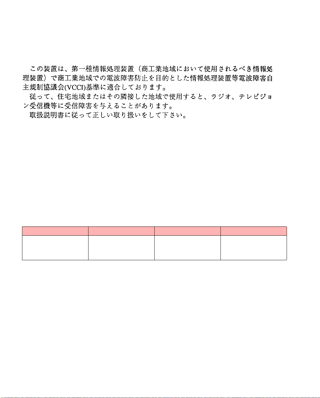
VCCI CLASS 1 NOTICE
This equipment is in the Class 1 category (Information Technology Equipment to be used in commercial and/or industrial
areas) and conforms to the standards set by the Voluntary Control Council For In terference by Information Technology
Equipment aimed at preventing radio interference in commercial and/or industrial areas.Consequently, when used in a
residential area or in an adjacent area thereto, radio interference may be caused to radios and TV receivers, etc. Read the
instructions for correct ha n dling.
FCC REQUIREMENTS (Notice to Users of DS1 Service)
The following instructions are prov ided to ensure compliance with the Federal Communica tions Commission (FCC) Rules,
Part 68.
(1) This device must only be connected to the DS1 network connected behind an FCC Part 68
registered channel service unit. Direct connection is not allowed.
(2) Before connecting your unit, you must inform the telephone company of the following
information:
Por t ID REN/SOC FIC USOC
NM-6/DS1C
NM-2/DS1C
NM-8/DS1D
NM-4/DS1D
6.0N 04DU9-BN,
04DU9-DN,
04DU9-1ZN, and
04DU9-1SN
(3) If the unit appears to be malfu nct ioni ng, it should be disc onn ecte d from the tel ephon e line s
until you learn if your equipment or the telephone line is the source of the trouble. If your
equipment needs repair, it should not be reconnected until it is repaired.
(4) If the telephone company finds that this equipment is exceeding tolerable parameters, the
telephone company can temporarily disconnect service, although they will attempt to give
you advance notice if possible .
(5) Under the FCC Ru les, no cust omer is au thorized to repair this equi pment. Th is restricti on
applies regardless of w he t h e r t he e quipment is in or out of war ran t y .
(6) If the telephone c ompany alters their equipment in a manner that will affect use of this
device, they must give you advance warning so as to give you the opportunity for uninterrupted service. You will be adv ised of your right to file a complain t wit h th e FCC .
RJ48C
Page 4
CANADIAN IC CS-03 COMPLIANCE STATEMENT
68
NOTICE: The Industry Canada label identifies certified equipment. This certi fic ation means tha t the equipment meets ce rtain telecommuni cations network protective, operational and safety requirements. The Industry Canada lab el does not
guarantee the equipment will operate to the user’s satisfaction.
Before installing this eq uipmen t, us ers shoul d ensure tha t it is permissi ble to be con ne cted to t he fa cilit ies of t he lo cal t elecommunications company. The equipment must also be installed using an acceptable method of connection. In some cases,
the company’s ins ide wi ring asso ciat ed wi th a sing le lin e i ndi vidu al s ervic e ma y be exte nded by m ean s of a cer tifie d c onnector assembly (telephone extens ion cor d). The cust omer should be aware that compliance with the above cond itions may
not prevent degradation of se rv ice in some situations.
Repairs to certified equipment should be made by an authorized Canadian maintenance facility designated by the supplier.
Any repairs or alterations made by the user to this equipment, or equipment malfunctions, may give the telecommunications company cause to request the user to disconnect the equipment.
Users should ensure for their own protection that the electrical ground connections of the power utility, telephone lines and
internal metall ic water pip e system, if prese nt, are connected together. This precaution may be particula rly important in
rural areas.
Caution
inspection authority, or electrician, as appropriate.
Users should not attempt to make suc h connections themselves, but should contact the appropriate elec tric
:
E1 AND E3 NOTICE
The E1 (NM-6/E1C, NM -2/E1C, NM-8 /E1D, and NM -4/E1D) and E3 (NM-4/E3C , NM-2/E3 C, NM-4/E3 D, and NM-2 /
E3D) network modu les that are descr ibed in this m anual are approved for us e in FORE Sy stems’ host s ystems providing
that the instructions below are strictly observed. Failure to follow these instructions invalidates the approval.
Pan European Approval - CE Marking
Pan European approval of the E1 network mod ule was issue d by BABT followi ng assessm ent against CT R12. This m eans
that it can be conn ected to ONP and unstruct ured PTO-provided private c ircuits with 120 Ω interfaces in all Europe an
countries, according to Telecommunications Terminal Equipment (TTE) Directive 91/263/ EEC. Thus, the following CE
mark applies:
1
The E1 and E3 network modules conform to safety standard EN60950: 1992 following the provisions of Low Voltage
Product Safety Directive 73/23/EEC and CE Marking Directive 93/68 /EEC, and can be mar ked accordingly with the CE
symbol.
The E1 and E3 netw ork modules conform to E N55022: 1994 and EN50082 -1: 1992 following the provision s of the EMC
Directive 89/336/EEC, and can be m arked accordingly with the CE symbo l.
X
Page 5
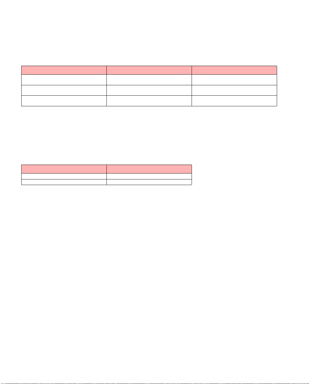
National Approvals
UK
Network Module Connects to Approval Number
E1 PTO-provided private circuits
E3 PTO-provided private circuits
CEM E1 PTO-provided private circuits
with 75
with 75 Ω interfaces
with 75 Ω interfaces
or 120 Ω unstructured interfaces
Ω
AA60953
NS/4387/1/T/605954
AA607478
Required User Guide Statements - UK Installation
The network modules are designed for use only with FORE Systems ATM Switches. Use of the network modules in any
product not listed in this manual may result in a hazard and will invalidate the regulatory approval. The network modules
must be installed in accordance with the installation instructions provided.
The following table show s t he av ailable ports and their safety stat us:
Ports Safety Status
E1 and E3 Ports TNV operating at SELV
Bus Connector SELV
CE
NOTICE
Marking by th e sy m bol CE indicates complian ce of this syst em to the EMC ( Electr o mag netic Compa tibil it y) directive of the
European Community and c ompliance to the Low Voltage (Safety) Directive . Such marking is indica tive that this syste m
meets or exceeds the follo wi ng te ch n ic al standards:
• EN 55022 - “Lim it s and Methods of Mea surem ent of Radio Interference Ch aracteristics of Inform at ion Technology Equipment.”
• EN 50082-1 - “Electromagnetic comp atibility - Generic immunity standa rd Part 1: Residential, comm ercial,
and light industry.”
• IEC 1000-4-2 - “El ectromagnetic compatib ility for industrial- process measurement and co ntrol equipment
Part 2: Electrostatic discharge requirements.”
• IEC 1000-4-3 - “El ectromagnetic compatib ility for industrial- process measurement and co ntrol equipment
Part 3: Radiate electromagnetic field requirements.”
• IEC 1000-4-4 - “El ectromagnetic compatib ility for industrial- process measurement and co ntrol equipment
Part 4: Electrical fast transien t /b urst requirements.”
SAFETY CERTIFICATIONS
ETL certified to meet Information Technology Equipmen t safe t y st an dards UL 1950, CSA 22.2 No. 950, and EN 6095 0.
Page 6

Page 7

Table of Contents
List of Figures
List of Tables
Preface
Chapter Summaries. . . . . . . . . . . . . . . . . . . . . . . . . . . . . . . . . . . . . . . . . . . . . . . . . . . . . . . . . . i
Technical Support . . . . . . . . . . . . . . . . . . . . . . . . . . . . . . . . . . . . . . . . . . . . . . . . . . . . . . . . . . .ii
Typographical Styles . . . . . . . . . . . . . . . . . . . . . . . . . . . . . . . . . . . . . . . . . . . . . . . . . . . . . . . . iii
Important Information Indicators . . . . . . . . . . . . . . . . . . . . . . . . . . . . . . . . . . . . . . . . . . . . . . . iv
Laser Radiation Notice . . . . . . . . . . . . . . . . . . . . . . . . . . . . . . . . . . . . . . . . . . . . . . . . . . . . . . .v
Safety Precautions. . . . . . . . . . . . . . . . . . . . . . . . . . . . . . . . . . . . . . . . . . . . . . . . . . . . . . . . . . vi
Modifications to Equipment . . . . . . . . . . . . . . . . . . . . . . . . . . . . . . . . . . . . . . . . . . . . vi
Placement of a FORE Systems Product . . . . . . . . . . . . . . . . . . . . . . . . . . . . . . . . . . vi
Power Cord Connection . . . . . . . . . . . . . . . . . . . . . . . . . . . . . . . . . . . . . . . . . . . . . . .vii
CHAPTER 1 Configuring PVCs
1.1 General Concepts. . . . . . . . . . . . . . . . . . . . . . . . . . . . . . . . . . . . . . . . . . . . . . . . . . 1 - 1
1.2 Virtual Paths . . . . . . . . . . . . . . . . . . . . . . . . . . . . . . . . . . . . . . . . . . . . . . . . . . . . . . 1 - 3
1.2.1 Through Paths . . . . . . . . . . . . . . . . . . . . . . . . . . . . . . . . . . . . . . . . . . . . 1 - 4
1.2.2 Originating and Terminating Paths. . . . . . . . . . . . . . . . . . . . . . . . . . . . . 1 - 6
1.3 Listing Virtual Paths . . . . . . . . . . . . . . . . . . . . . . . . . . . . . . . . . . . . . . . . . . . . . . . . 1 - 7
1.3.1 Listing Through Paths. . . . . . . . . . . . . . . . . . . . . . . . . . . . . . . . . . . . . . . 1 - 7
1.3.2 Listing Originating and Terminating Paths . . . . . . . . . . . . . . . . . . . . . . . 1 - 9
1.4 Virtual Channels. . . . . . . . . . . . . . . . . . . . . . . . . . . . . . . . . . . . . . . . . . . . . . . . . . 1 - 11
1.4.1 Smart Permanent Virtual Circuits. . . . . . . . . . . . . . . . . . . . . . . . . . . . . 1 - 14
1.4.2 Listing Virtual Channels . . . . . . . . . . . . . . . . . . . . . . . . . . . . . . . . . . . . 1 - 15
1.5 Creating PVCs and SPVCs . . . . . . . . . . . . . . . . . . . . . . . . . . . . . . . . . . . . . . . . . 1 - 17
1.5.1 Creating a Through Path . . . . . . . . . . . . . . . . . . . . . . . . . . . . . . . . . . . 1 - 18
1.5.2 Creating an Originating or Terminating Path . . . . . . . . . . . . . . . . . . . . 1 - 21
1.5.2.1 Shaping Multiple Originating Paths on a Single Port. . . . . . . . 1 - 24
1.5.2.2 Terminating a PVC at a Switch . . . . . . . . . . . . . . . . . . . . . . . .1 - 27
1.5.2.3 Creating ATM ARP Entries . . . . . . . . . . . . . . . . . . . . . . . . . . .1 - 28
1.5.2.4 Listing ATM ARP Entries . . . . . . . . . . . . . . . . . . . . . . . . . . . . .1 - 29
1.5.3 Creating a Virtual Channel. . . . . . . . . . . . . . . . . . . . . . . . . . . . . . . . . . 1 - 30
1.5.4 Creating a SPANS SPVC . . . . . . . . . . . . . . . . . . . . . . . . . . . . . . . . . . . 1 - 32
1.5.5 Displaying SPANS SPVC Information . . . . . . . . . . . . . . . . . . . . . . . . . 1 - 33
ForeRunner
ATM Switch Network Configuration Manual
TOC - 1
Page 8

Table of Contents
1.6 Traffic Types. . . . . . . . . . . . . . . . . . . . . . . . . . . . . . . . . . . . . . . . . . . . . . . . . . . . . 1 - 35
1.7 Traffic Policing (Usage Parameter Control) . . . . . . . . . . . . . . . . . . . . . . . . . . . . . 1 - 36
1.7.1 Leaky Bucket Algorithm. . . . . . . . . . . . . . . . . . . . . . . . . . . . . . . . . . . . 1 - 36
1.7.2 Non-conforming Cells: T agging vs. Dropping . . . . . . . . . . . . . . . . . . . 1 - 37
1.7.3 UPC Traffic Contract Parameters . . . . . . . . . . . . . . . . . . . . . . . . . . . . 1 - 37
1.7.4 AMI UPC Commands . . . . . . . . . . . . . . . . . . . . . . . . . . . . . . . . . . . . . 1 - 39
CHAPTER 2 Configuring Classical IP
2.1 Introduction . . . . . . . . . . . . . . . . . . . . . . . . . . . . . . . . . . . . . . . . . . . . . . . . . . . . . . 2 - 1
2.1.1 Logical IP Subnets . . . . . . . . . . . . . . . . . . . . . . . . . . . . . . . . . . . . . . . . 2 - 2
2.1.2 Classical IP Interfaces. . . . . . . . . . . . . . . . . . . . . . . . . . . . . . . . . . . . . . 2 - 2
2.1.3 SPANS Interface . . . . . . . . . . . . . . . . . . . . . . . . . . . . . . . . . . . . . . . . . . 2 - 3
2.2 Address Registration and ILMI . . . . . . . . . . . . . . . . . . . . . . . . . . . . . . . . . . . . . . . 2 - 4
2.2.1 NSAP Addresses. . . . . . . . . . . . . . . . . . . . . . . . . . . . . . . . . . . . . . . . . . 2 - 4
2.2.2 Operating with ILMI Support . . . . . . . . . . . . . . . . . . . . . . . . . . . . . . . . . 2 - 5
2.2.3 Operating without ILMI Support. . . . . . . . . . . . . . . . . . . . . . . . . . . . . . . 2 - 5
2.2.4 Configuration. . . . . . . . . . . . . . . . . . . . . . . . . . . . . . . . . . . . . . . . . . . . . 2 - 5
2.3 ARP and ARP Servers . . . . . . . . . . . . . . . . . . . . . . . . . . . . . . . . . . . . . . . . . . . . . 2 - 6
2.3.1 Theory . . . . . . . . . . . . . . . . . . . . . . . . . . . . . . . . . . . . . . . . . . . . . . . . . . 2 - 6
2.3.2 Configuring a FORE Switch to be an ARP Server . . . . . . . . . . . . . . . . 2 - 7
2.3.3 Classical IP Operation. . . . . . . . . . . . . . . . . . . . . . . . . . . . . . . . . . . . . . 2 - 8
2.3.4 Operational Issues. . . . . . . . . . . . . . . . . . . . . . . . . . . . . . . . . . . . . . . . . 2 - 9
2.4 Classical IP PVCs . . . . . . . . . . . . . . . . . . . . . . . . . . . . . . . . . . . . . . . . . . . . . . . . 2 - 10
2.4.1 Theory and Configuration . . . . . . . . . . . . . . . . . . . . . . . . . . . . . . . . . . 2 - 10
2.4.2 Revalidation and Removal. . . . . . . . . . . . . . . . . . . . . . . . . . . . . . . . . . 2 - 10
2.5 Configuring the Network . . . . . . . . . . . . . . . . . . . . . . . . . . . . . . . . . . . . . . . . . . . 2 - 11
2.5.1 Third-Party Host with No ILMI and No RFC-1577 Support . . . . . . . . . 2 - 12
2.5.2 Third-Party Switch with ILMI and No RFC-1577 Support . . . . . . . . . . 2 - 13
2.5.3 Third-Party Switch with RFC-1577 and No ILMI Support . . . . . . . . . . 2 - 14
CHAPTER 3 Configuring an Emulated LAN
3.1 Introduction . . . . . . . . . . . . . . . . . . . . . . . . . . . . . . . . . . . . . . . . . . . . . . . . . . . . . . 3 - 1
3.1.1 Ethernet ELANs. . . . . . . . . . . . . . . . . . . . . . . . . . . . . . . . . . . . . . . . . . . 3 - 1
3.1.2 Token Ring ELANs . . . . . . . . . . . . . . . . . . . . . . . . . . . . . . . . . . . . . . . . 3 - 1
3.2 ELAN Components . . . . . . . . . . . . . . . . . . . . . . . . . . . . . . . . . . . . . . . . . . . . . . . . 3 - 2
3.2.1 LAN Emulation Client (LEC) . . . . . . . . . . . . . . . . . . . . . . . . . . . . . . . . . 3 - 3
3.2.2 LAN Emulation Configuration Server (LECS) . . . . . . . . . . . . . . . . . . . . 3 - 3
3.2.3 LAN Emulation Server (LES). . . . . . . . . . . . . . . . . . . . . . . . . . . . . . . . . 3 - 3
3.2.4 Broadcast and Unknown Server (BUS). . . . . . . . . . . . . . . . . . . . . . . . . 3 - 3
3.3 Emulated LAN Operation. . . . . . . . . . . . . . . . . . . . . . . . . . . . . . . . . . . . . . . . . . . . 3 - 4
3.3.1 Initialization . . . . . . . . . . . . . . . . . . . . . . . . . . . . . . . . . . . . . . . . . . . . . . 3 - 6
TOC - 2
ForeRunner
ATM Switch Network Configuration Manual
Page 9

Table of Contents
3.3.2 Registration and Address Resolution. . . . . . . . . . . . . . . . . . . . . . . . . . . 3 - 7
3.3.3 Data Transfer . . . . . . . . . . . . . . . . . . . . . . . . . . . . . . . . . . . . . . . . . . . . . 3 - 8
3.4 Distributed LAN Emulation . . . . . . . . . . . . . . . . . . . . . . . . . . . . . . . . . . . . . . . . . . .3 - 9
3.4.1 Single Server LANE Services Model . . . . . . . . . . . . . . . . . . . . . . . . . . . 3 - 9
3.4.1.1 Using a Single Server . . . . . . . . . . . . . . . . . . . . . . . . . . . . . . . 3 - 10
3.4.1.2 Limitations of a Single Server . . . . . . . . . . . . . . . . . . . . . . . . .3 - 11
3.4.2 Distributed LAN Emulation Model. . . . . . . . . . . . . . . . . . . . . . . . . . . . . 3 - 12
3.4.2.1 Using DLE . . . . . . . . . . . . . . . . . . . . . . . . . . . . . . . . . . . . . . . . 3 - 13
3.4.2.2 Advantages of DLE . . . . . . . . . . . . . . . . . . . . . . . . . . . . . . . . .3 - 15
3.4.2.2.1 Load Sharing . . . . . . . . . . . . . . . . . . . . . . . . . . . . . 3 - 15
3.4.2.2.2 Improved P erformance for Remote LECs. . . . . . . . 3 - 15
3.4.2.2.3 Fault Tolerance . . . . . . . . . . . . . . . . . . . . . . . . . . . . 3 - 15
3.4.2.2.3.1 Single Server ELAN. . . . . . . . . . . . . . . . 3 - 16
3.4.2.2.3.2 DLE ELAN . . . . . . . . . . . . . . . . . . . . . . . 3 - 18
3.5 ELAN Access Control. . . . . . . . . . . . . . . . . . . . . . . . . . . . . . . . . . . . . . . . . . . . . .3 - 21
3.6 Configuring an ELAN . . . . . . . . . . . . . . . . . . . . . . . . . . . . . . . . . . . . . . . . . . . . . . 3 - 22
3.6.1 Configuring an LECS Configuration Database File . . . . . . . . . . . . . . . 3 - 23
3.6.1.1 Before You Begin. . . . . . . . . . . . . . . . . . . . . . . . . . . . . . . . . . . 3 - 23
3.6.1.2 LECS Configuration File Syntax . . . . . . . . . . . . . . . . . . . . . . . 3 - 24
3.6.1.3 Defining an ELAN . . . . . . . . . . . . . . . . . . . . . . . . . . . . . . . . . . 3 - 30
3.6.1.4 Defining a Client . . . . . . . . . . . . . . . . . . . . . . . . . . . . . . . . . . . 3 - 31
3.6.1.5 LECS Control Parameters. . . . . . . . . . . . . . . . . . . . . . . . . . . . 3 - 32
3.6.1.6 LECS MPOA Parameters . . . . . . . . . . . . . . . . . . . . . . . . . . . . 3 - 33
3.6.2 Sample LECS Configuration File . . . . . . . . . . . . . . . . . . . . . . . . . . . . . 3 - 35
3.6.3 Starting the LAN Emulation Services. . . . . . . . . . . . . . . . . . . . . . . . . . 3 - 38
3.6.3.1 Starting the LECS . . . . . . . . . . . . . . . . . . . . . . . . . . . . . . . . . . 3 - 38
3.6.3.2 Starting the DLE LES/BUS Peer Servers . . . . . . . . . . . . . . . . 3 - 40
3.6.4 Starting the LEC(s) and Joining an ELAN . . . . . . . . . . . . . . . . . . . . . .3 - 42
3.7 Upgrading an ELAN to Use DLE . . . . . . . . . . . . . . . . . . . . . . . . . . . . . . . . . . . . . 3 - 44
3.7.1 Edit the LECS.CFG File . . . . . . . . . . . . . . . . . . . . . . . . . . . . . . . . . . . . 3 - 45
3.7.2 Delete the LES and BUS . . . . . . . . . . . . . . . . . . . . . . . . . . . . . . . . . . .3 - 46
3.7.3 Upgrade the Switches Running Services. . . . . . . . . . . . . . . . . . . . . . . 3 - 47
3.7.4 Create the DLE Peer Servers. . . . . . . . . . . . . . . . . . . . . . . . . . . . . . . .3 - 47
3.7.5 Transfer the Updated LECS.CFG File . . . . . . . . . . . . . . . . . . . . . . . . . 3 - 48
3.7.6 Restart the LECS . . . . . . . . . . . . . . . . . . . . . . . . . . . . . . . . . . . . . . . . . 3 - 49
3.7.7 Recreate the LECs. . . . . . . . . . . . . . . . . . . . . . . . . . . . . . . . . . . . . . . . 3 - 49
3.7.8 Create the Last DLE Peer . . . . . . . . . . . . . . . . . . . . . . . . . . . . . . . . . . 3 - 51
3.7.9 Add the Last DLE Peer to Each Peer List. . . . . . . . . . . . . . . . . . . . . . . 3 - 51
3.7.10 Update the LECS.CFG File . . . . . . . . . . . . . . . . . . . . . . . . . . . . . . . . . 3 - 52
3.7.11 Transfer the Final LECS.CFG File . . . . . . . . . . . . . . . . . . . . . . . . . . . . 3 - 52
3.7.12 Restart the LECS . . . . . . . . . . . . . . . . . . . . . . . . . . . . . . . . . . . . . . . . . 3 - 53
ForeRunner
ATM Switch Network Configuration Manual
TOC - 3
Page 10

Table of Contents
3.8 Upgrading an ELAN without Using DLE . . . . . . . . . . . . . . . . . . . . . . . . . . . . . . . 3 - 54
3.8.1 Deleting the Non Co-located Services . . . . . . . . . . . . . . . . . . . . . . . . 3 - 55
3.8.1.1 Administer Down the Services . . . . . . . . . . . . . . . . . . . . . . . . 3 - 55
3.8.1.2 Delete the Non Co-located LES and BUS . . . . . . . . . . . . . . . 3 - 55
3.8.1.2.1 Edit the LECS.CFG File. . . . . . . . . . . . . . . . . . . . . 3 - 55
3.8.2 Upgrade the Switches Running Services . . . . . . . . . . . . . . . . . . . . . . 3 - 56
3.8.3 Recreate the LES and BUS Together . . . . . . . . . . . . . . . . . . . . . . . . . 3 - 56
3.8.4 Administer the Services Up. . . . . . . . . . . . . . . . . . . . . . . . . . . . . . . . . 3 - 57
CHAPTER 4 MPOA
4.1 Overview of LANE/MPOA . . . . . . . . . . . . . . . . . . . . . . . . . . . . . . . . . . . . . . . . . . . 4 - 1
4.2 LANE Primer . . . . . . . . . . . . . . . . . . . . . . . . . . . . . . . . . . . . . . . . . . . . . . . . . . . . . 4 - 2
4.2.1 LANE Components . . . . . . . . . . . . . . . . . . . . . . . . . . . . . . . . . . . . . . . . 4 - 2
4.2.2 An Example LANE Configuration . . . . . . . . . . . . . . . . . . . . . . . . . . . . . 4 - 3
4.2.2.1 The Initialization Process . . . . . . . . . . . . . . . . . . . . . . . . . . . . . 4 - 4
4.2.2.2 The Connection Process . . . . . . . . . . . . . . . . . . . . . . . . . . . . . 4 - 5
4.2.2.3 Multicast and Broadcast Packets . . . . . . . . . . . . . . . . . . . . . . . 4 - 5
4.2.2.4 Accessing Fast Ethernet and FDDI Networks . . . . . . . . . . . . . 4 - 5
4.2.2.5 Multiple ELANs. . . . . . . . . . . . . . . . . . . . . . . . . . . . . . . . . . . . . 4 - 6
4.2.2.6 Distributed LAN Emulation . . . . . . . . . . . . . . . . . . . . . . . . . . . . 4 - 6
4.2.2.7 Automatic ELAN Selection . . . . . . . . . . . . . . . . . . . . . . . . . . . . 4 - 6
4.2.2.8 Intelligent BUS . . . . . . . . . . . . . . . . . . . . . . . . . . . . . . . . . . . . . 4 - 6
4.3 An Introduction to Multi-Protocol Over ATM. . . . . . . . . . . . . . . . . . . . . . . . . . . . . . 4 - 7
4.3.1 LANE Without MPOA . . . . . . . . . . . . . . . . . . . . . . . . . . . . . . . . . . . . . . 4 - 7
4.3.2 Why MPOA? . . . . . . . . . . . . . . . . . . . . . . . . . . . . . . . . . . . . . . . . . . . . . 4 - 8
4.3.3 MPOA Components. . . . . . . . . . . . . . . . . . . . . . . . . . . . . . . . . . . . . . . 4 - 10
4.3.4 MPOA Example. . . . . . . . . . . . . . . . . . . . . . . . . . . . . . . . . . . . . . . . . . 4 - 11
4.3.4.1 MPS Configuration . . . . . . . . . . . . . . . . . . . . . . . . . . . . . . . . . 4 - 12
4.3.4.2 Initialization. . . . . . . . . . . . . . . . . . . . . . . . . . . . . . . . . . . . . . . 4 - 12
4.3.4.3 Flow Analysis . . . . . . . . . . . . . . . . . . . . . . . . . . . . . . . . . . . . . 4 - 13
4.3.4.4 Making a Shortcut . . . . . . . . . . . . . . . . . . . . . . . . . . . . . . . . . 4 - 13
4.3.4.5 Shortcut Teardown . . . . . . . . . . . . . . . . . . . . . . . . . . . . . . . . . 4 - 14
CHAPTER 5
ForeThought
PNNI
5.1 FT-PNNI Routing . . . . . . . . . . . . . . . . . . . . . . . . . . . . . . . . . . . . . . . . . . . . . . . . . . 5 - 2
5.1.1 Hello Protocol . . . . . . . . . . . . . . . . . . . . . . . . . . . . . . . . . . . . . . . . . . . . 5 - 2
5.1.2 Topology Database Exchange. . . . . . . . . . . . . . . . . . . . . . . . . . . . . . . . 5 - 2
5.1.3 Flooding. . . . . . . . . . . . . . . . . . . . . . . . . . . . . . . . . . . . . . . . . . . . . . . . . 5 - 2
5.1.4 Hierarchical Routing . . . . . . . . . . . . . . . . . . . . . . . . . . . . . . . . . . . . . . . 5 - 3
TOC - 4
ForeRunner
ATM Switch Network Configuration Manual
Page 11

Table of Contents
5.1.4.1 Hierarchical Addressing. . . . . . . . . . . . . . . . . . . . . . . . . . . . . . . 5 - 3
5.1.4.1.1 Switch Prefix. . . . . . . . . . . . . . . . . . . . . . . . . . . . . . . 5 - 3
5.1.4.1.2 Switch Summary Prefix . . . . . . . . . . . . . . . . . . . . . .5 - 4
5.1.4.1.3 Peer Group ID. . . . . . . . . . . . . . . . . . . . . . . . . . . . . . 5 - 4
5.1.4.2 Path Computation . . . . . . . . . . . . . . . . . . . . . . . . . . . . . . . . . . . 5 - 4
5.2 The Physical Network. . . . . . . . . . . . . . . . . . . . . . . . . . . . . . . . . . . . . . . . . . . . . . . 5 - 5
5.2.1 Peer Groups. . . . . . . . . . . . . . . . . . . . . . . . . . . . . . . . . . . . . . . . . . . . . . 5 - 8
5.2.2 Peer Group Topology . . . . . . . . . . . . . . . . . . . . . . . . . . . . . . . . . . . . . . . 5 - 8
5.2.3 Border Switches . . . . . . . . . . . . . . . . . . . . . . . . . . . . . . . . . . . . . . . . . . .5 - 8
5.2.4 Peer Group Summary Node (PGSN) . . . . . . . . . . . . . . . . . . . . . . . . . . . 5 - 9
5.2.5 Backbone Topology . . . . . . . . . . . . . . . . . . . . . . . . . . . . . . . . . . . . . . . . 5 - 9
5.2.6 Single Switch Perspective . . . . . . . . . . . . . . . . . . . . . . . . . . . . . . . . . . . 5 - 9
CHAPTER 6 ATM Forum PNNI
6.1 PNNI Routing Protocol . . . . . . . . . . . . . . . . . . . . . . . . . . . . . . . . . . . . . . . . . . . . . .6 - 1
6.1.1 Hello Protocol. . . . . . . . . . . . . . . . . . . . . . . . . . . . . . . . . . . . . . . . . . . . . 6 - 1
6.1.2 Database Exchange Protocol. . . . . . . . . . . . . . . . . . . . . . . . . . . . . . . . .6 - 2
6.1.3 Flooding Protocol . . . . . . . . . . . . . . . . . . . . . . . . . . . . . . . . . . . . . . . . . . 6 - 2
6.1.4 Path Computation. . . . . . . . . . . . . . . . . . . . . . . . . . . . . . . . . . . . . . . . . . 6 - 2
6.1.5 Hierarchical Routing . . . . . . . . . . . . . . . . . . . . . . . . . . . . . . . . . . . . . . . . 6 - 3
6.2 PNNI Signalling Protocol . . . . . . . . . . . . . . . . . . . . . . . . . . . . . . . . . . . . . . . . . . . . 6 - 4
6.2.1 Source Routing. . . . . . . . . . . . . . . . . . . . . . . . . . . . . . . . . . . . . . . . . . . . 6 - 4
6.2.2 Crankback . . . . . . . . . . . . . . . . . . . . . . . . . . . . . . . . . . . . . . . . . . . . . . . 6 - 4
6.3 Internetworking between PNNI and FT-PNNI. . . . . . . . . . . . . . . . . . . . . . . . . . . . . 6 - 5
6.3.1 Gateway Switches and Split Switches . . . . . . . . . . . . . . . . . . . . . . . . . .6 - 5
6.3.2 Dynamic Leaking of Reachability Information . . . . . . . . . . . . . . . . . . . . 6 - 6
6.3.2.1 Areas. . . . . . . . . . . . . . . . . . . . . . . . . . . . . . . . . . . . . . . . . . . . . 6 - 6
6.3.2.1.1 Peer Groups in Areas. . . . . . . . . . . . . . . . . . . . . . . . 6 - 7
6.3.2.1.2 Area IDs . . . . . . . . . . . . . . . . . . . . . . . . . . . . . . . . . . 6 - 7
6.3.2.1.3 Levels . . . . . . . . . . . . . . . . . . . . . . . . . . . . . . . . . . . . 6 - 8
6.3.2.2 Domains . . . . . . . . . . . . . . . . . . . . . . . . . . . . . . . . . . . . . . . . . . 6 - 8
6.3.2.2.1 Configuring Domains . . . . . . . . . . . . . . . . . . . . . . . .6 - 9
6.3.2.3 Propagation of Reachability Information . . . . . . . . . . . . . . . . . 6 - 10
6.3.2.3.1 Policies . . . . . . . . . . . . . . . . . . . . . . . . . . . . . . . . . . 6 - 10
6.3.2.3.2 Scope . . . . . . . . . . . . . . . . . . . . . . . . . . . . . . . . . . . 6 - 10
6.3.2.3.3 The Process for Leaking Reachability
Information . . . . . . . . . . . . . . . . . . . . . . . . . . . . . . . 6 - 11
6.3.2.4 VP Trunk QoS Extension. . . . . . . . . . . . . . . . . . . . . . . . . . . . . 6 - 11
ForeRunner
ATM Switch Network Configuration Manual
TOC - 5
Page 12

Table of Contents
CHAPTER 7 Signalling
7.1 VCI Allocation Range . . . . . . . . . . . . . . . . . . . . . . . . . . . . . . . . . . . . . . . . . . . . . . 7 - 1
7.1.1 Determining the VCI Allocation Range with ILMI Down . . . . . . . . . . . . 7 - 2
7.1.2 Determining the VCI Allocation Range with ILMI Up. . . . . . . . . . . . . . . 7 - 4
7.2 Signalling Scope . . . . . . . . . . . . . . . . . . . . . . . . . . . . . . . . . . . . . . . . . . . . . . . . . . 7 - 7
7.2.1 VC-Space . . . . . . . . . . . . . . . . . . . . . . . . . . . . . . . . . . . . . . . . . . . . . . . 7 - 7
7.2.2 Dynamic Paths . . . . . . . . . . . . . . . . . . . . . . . . . . . . . . . . . . . . . . . . . . . 7 - 8
7.3 Signalling Channel Auto Configuration Procedures. . . . . . . . . . . . . . . . . . . . . . . . 7 - 9
7.3.1 Overview of Signalling Channel Auto Configuration . . . . . . . . . . . . . . . 7 - 9
7.3.2 Rules for Signalling Channel Auto Configuration. . . . . . . . . . . . . . . . . 7 - 12
7.3.2.1 Specifying the Type and Interface Version . . . . . . . . . . . . . . . 7 - 12
7.3.2.1.1 Examples of Valid Configurations . . . . . . . . . . . . . 7 - 13
7.3.2.1.2 Examples of Invalid Configurations . . . . . . . . . . . . 7 - 14
7.3.2.2 Specifying the Scope and Mode. . . . . . . . . . . . . . . . . . . . . . . 7 - 15
7.3.2.2.1 Examples of Valid Configurations . . . . . . . . . . . . . 7 - 16
7.3.2.2.2 Examples of Invalid Configurations . . . . . . . . . . . . 7 - 16
7.4 Allowable Combination of Traffic Parameters . . . . . . . . . . . . . . . . . . . . . . . . . . . 7 - 18
7.4.1 PNNI 1.0/UNI 4.0. . . . . . . . . . . . . . . . . . . . . . . . . . . . . . . . . . . . . . . . . 7 - 18
7.4.1.1 Service Categories. . . . . . . . . . . . . . . . . . . . . . . . . . . . . . . . . 7 - 18
7.4.1.2 Allowable Combination of Traffic Parameters. . . . . . . . . . . . . 7 - 18
7.4.2 UNI 3.X . . . . . . . . . . . . . . . . . . . . . . . . . . . . . . . . . . . . . . . . . . . . . . . . 7 - 19
CHAPTER 8 Security
8.1 Configuring Userids. . . . . . . . . . . . . . . . . . . . . . . . . . . . . . . . . . . . . . . . . . . . . . . . 8 - 1
8.1.1 Login Authentication Method. . . . . . . . . . . . . . . . . . . . . . . . . . . . . . . . . 8 - 3
8.1.1.1 Local Authentication . . . . . . . . . . . . . . . . . . . . . . . . . . . . . . . . . 8 - 3
8.1.1.2 SecurID Authentication. . . . . . . . . . . . . . . . . . . . . . . . . . . . . . . 8 - 3
8.1.1.2.1 SecurID Protection on Switches . . . . . . . . . . . . . . . 8 - 3
8.1.1.2.2 SecurID Passcode. . . . . . . . . . . . . . . . . . . . . . . . . . 8 - 4
8.1.1.2.2.1 PIN Number . . . . . . . . . . . . . . . . . . . . . . 8 - 4
8.1.1.2.2.2 SecurID Tokens. . . . . . . . . . . . . . . . . . . . 8 - 4
8.1.1.2.3 SecurID Server . . . . . . . . . . . . . . . . . . . . . . . . . . . . 8 - 4
8.1.1.2.3.1 Slave Server . . . . . . . . . . . . . . . . . . . . . . 8 - 4
8.1.1.2.3.2 Server Database. . . . . . . . . . . . . . . . . . . 8 - 4
8.1.1.2.3.3 Data Encryption between the Server
and Switches . . . . . . . . . . . . . . . . . . . . . 8 - 5
8.1.1.2.4 SecurID AMI Commands. . . . . . . . . . . . . . . . . . . . . 8 - 5
8.1.1.2.5 Installing SecurID on a Switch. . . . . . . . . . . . . . . . . 8 - 5
8.1.1.2.5.1 Installing the Server Software. . . . . . . . . 8 - 5
8.1.1.2.5.2 Transferring the Configuration File . . . . . 8 - 5
8.1.1.2.5.3 Editing the Server Configuration File . . . 8 - 6
8.1.1.2.5.4 An Example Login Using SecurID . . . . . 8 - 8
TOC - 6
ForeRunner
ATM Switch Network Configuration Manual
Page 13

Table of Contents
8.1.2 AMI Command Privileges. . . . . . . . . . . . . . . . . . . . . . . . . . . . . . . . . . . .8 - 9
8.1.2.1 Admin Privileges . . . . . . . . . . . . . . . . . . . . . . . . . . . . . . . . . . . .8 - 9
8.1.2.2 User Privileges . . . . . . . . . . . . . . . . . . . . . . . . . . . . . . . . . . . . . 8 - 9
8.1.3 AMI Access Levels. . . . . . . . . . . . . . . . . . . . . . . . . . . . . . . . . . . . . . . . . 8 - 9
8.1.3.1 Serial Access. . . . . . . . . . . . . . . . . . . . . . . . . . . . . . . . . . . . . . . 8 - 9
8.1.3.2 Network Access. . . . . . . . . . . . . . . . . . . . . . . . . . . . . . . . . . . . . 8 - 9
8.1.3.3 All Access . . . . . . . . . . . . . . . . . . . . . . . . . . . . . . . . . . . . . . . . . 8 - 9
8.1.3.4 No Access . . . . . . . . . . . . . . . . . . . . . . . . . . . . . . . . . . . . . . . . . 8 - 9
8.1.4 Userid Password . . . . . . . . . . . . . . . . . . . . . . . . . . . . . . . . . . . . . . . . . 8 - 10
8.1.5 Privilege Level for Unlisted Users. . . . . . . . . . . . . . . . . . . . . . . . . . . . . 8 - 10
8.2 IP Filtering . . . . . . . . . . . . . . . . . . . . . . . . . . . . . . . . . . . . . . . . . . . . . . . . . . . . . . 8 - 11
8.2.1 Authorized IP Address Table . . . . . . . . . . . . . . . . . . . . . . . . . . . . . . . . 8 - 11
8.2.2 IP Filtering Flags . . . . . . . . . . . . . . . . . . . . . . . . . . . . . . . . . . . . . . . . . 8 - 11
8.2.2.1 Strict Source Routing Flag . . . . . . . . . . . . . . . . . . . . . . . . . . . 8 - 12
8.2.2.2 Loose Source Routing Flag. . . . . . . . . . . . . . . . . . . . . . . . . . . 8 - 12
8.2.2.3 All Flag . . . . . . . . . . . . . . . . . . . . . . . . . . . . . . . . . . . . . . . . . . 8 - 12
8.2.3 IP Access Statistics . . . . . . . . . . . . . . . . . . . . . . . . . . . . . . . . . . . . . . . 8 - 12
8.3 NSAP Filtering . . . . . . . . . . . . . . . . . . . . . . . . . . . . . . . . . . . . . . . . . . . . . . . . . . .8 - 13
8.3.1 Filters and Templates . . . . . . . . . . . . . . . . . . . . . . . . . . . . . . . . . . . . . . 8 - 13
8.3.2 NSAP Filtering Lookup . . . . . . . . . . . . . . . . . . . . . . . . . . . . . . . . . . . . . 8 - 14
8.3.3 NSAP Filtering Statistics . . . . . . . . . . . . . . . . . . . . . . . . . . . . . . . . . . .8 - 14
CHAPTER 9 Configuring Timing
9.1 Overview. . . . . . . . . . . . . . . . . . . . . . . . . . . . . . . . . . . . . . . . . . . . . . . . . . . . . . . . . 9 - 1
9.2 Timing Modes. . . . . . . . . . . . . . . . . . . . . . . . . . . . . . . . . . . . . . . . . . . . . . . . . . . . . 9 - 1
9.3 Switchclock. . . . . . . . . . . . . . . . . . . . . . . . . . . . . . . . . . . . . . . . . . . . . . . . . . . . . . . 9 - 2
9.3.1 Failover of the Switchclock . . . . . . . . . . . . . . . . . . . . . . . . . . . . . . . . . . . 9 - 2
9.4 Port Level Timing . . . . . . . . . . . . . . . . . . . . . . . . . . . . . . . . . . . . . . . . . . . . . . . . . . 9 - 3
9.5 Timing Configuration Examples . . . . . . . . . . . . . . . . . . . . . . . . . . . . . . . . . . . . . . . 9 - 4
9.5.1 Configuring Timing on an ASX-200BX or ASX-200WG . . . . . . . . . . . . . 9 - 4
9.5.2 Configuring Timing on an ASX-1000 (Single Timing Domain) . . . . . . . . 9 - 4
9.5.3 Configuring Timing on an ASX-1000 (Multiple Timing Domains). . . . . .9 - 5
9.5.4 Configuring Timing on a ForeRunnerLE 155 . . . . . . . . . . . . . . . . . . . . .9 - 5
APPENDIX A Configuring SNMP
A.1 SNMP Indexing. . . . . . . . . . . . . . . . . . . . . . . . . . . . . . . . . . . . . . . . . . . . . . . . . . . .A - 1
A.2 SNMP Traps . . . . . . . . . . . . . . . . . . . . . . . . . . . . . . . . . . . . . . . . . . . . . . . . . . . . . .A - 3
A.2.1 Adding SNMP Trap Destinations . . . . . . . . . . . . . . . . . . . . . . . . . . . . .A - 21
A.2.2 Displaying SNMP Trap Destinations. . . . . . . . . . . . . . . . . . . . . . . . . . .A - 21
A.2.3 Removing SNMP Trap Destinations. . . . . . . . . . . . . . . . . . . . . . . . . . .A - 22
ForeRunner
ATM Switch Network Configuration Manual
TOC - 7
Page 14

Table of Contents
APPENDIX B Configuring Circuit Emulation Services
B.1 Configuring CES Connections. . . . . . . . . . . . . . . . . . . . . . . . . . . . . . . . . . . . . . . . B - 2
B.1.1 Creating a New CES Connection . . . . . . . . . . . . . . . . . . . . . . . . . . . . . B - 2
B.1.2 Displaying CES Connections. . . . . . . . . . . . . . . . . . . . . . . . . . . . . . . . . B - 5
APPENDIX C Converting from FT-PNNI to P NNI
C.1 ASX-1000 Routing Configuration Issues . . . . . . . . . . . . . . . . . . . . . . . . . . . . . . . . C - 2
C.1.1 ASX-1000s in FT-PNNI Peer Groups. . . . . . . . . . . . . . . . . . . . . . . . . . . C - 2
C.1.2 ASX-1000s in PNNI Areas . . . . . . . . . . . . . . . . . . . . . . . . . . . . . . . . . . C - 3
C.1.3 Multiple Gateways in an ASX-1000 . . . . . . . . . . . . . . . . . . . . . . . . . . . . C - 4
C.1.4 Migrating from FT-PNNI to PNNI Routing . . . . . . . . . . . . . . . . . . . . . . . C - 4
C.2 Migration of a Non-Hierarchical FT-PNNI Network . . . . . . . . . . . . . . . . . . . . . . . . C - 5
C.2.1 Migration Overview . . . . . . . . . . . . . . . . . . . . . . . . . . . . . . . . . . . . . . . . C - 5
C.2.2 Detailed Migration Example. . . . . . . . . . . . . . . . . . . . . . . . . . . . . . . . . . C - 6
C.3 Migration of a Hierarchical FT-PNNI Network . . . . . . . . . . . . . . . . . . . . . . . . . . . C - 10
C.3.1 Migration of a Hierarchical FT-PNNI Network with a
Contiguous Backbone . . . . . . . . . . . . . . . . . . . . . . . . . . . . . . . . . . . . . C - 10
C.3.1.1 Migration Starting with the Backbone. . . . . . . . . . . . . . . . . . . C - 10
C.3.1.1.1 Migration Overview . . . . . . . . . . . . . . . . . . . . . . . . C - 11
C.3.1.1.1.1 Upgrade the Switches. . . . . . . . . . . . . . C - 11
C.3.1.1.1.2 Convert the Backbone . . . . . . . . . . . . . C - 11
C.3.1.1.1.3 Convert the Individual Peer Groups . . . C - 14
C.3.1.2 Migration Starting with the Peer Groups. . . . . . . . . . . . . . . . . C - 19
C.3.1.2.1 Overview of the Migration . . . . . . . . . . . . . . . . . . . C - 19
C.3.1.2.1.1 Upgrade the Switches. . . . . . . . . . . . . . C - 19
C.3.1.2.1.2 Convert Peer Group C . . . . . . . . . . . . . C - 19
C.3.1.2.1.3 Convert Peer Group A . . . . . . . . . . . . . C - 23
C.3.1.2.1.4 Convert the Backbone . . . . . . . . . . . . . C - 23
C.3.1.2.1.5 Convert Peer Group B . . . . . . . . . . . . . C - 26
C.3.2 Migration of a Hierarchical FT-PNNI Network with a
Non-Contiguous Backbone . . . . . . . . . . . . . . . . . . . . . . . . . . . . . . . . . C - 27
APPENDIX D Configuring
FramePlus
Modules
D.1 Frame Relay Overview . . . . . . . . . . . . . . . . . . . . . . . . . . . . . . . . . . . . . . . . . . . . . D - 2
D.1.1 Interworking Function (IWF) . . . . . . . . . . . . . . . . . . . . . . . . . . . . . . . . . D - 2
D.1.1.1 Translation Mode . . . . . . . . . . . . . . . . . . . . . . . . . . . . . . . . . . . D - 2
D.1.1.2 Transparent Mode. . . . . . . . . . . . . . . . . . . . . . . . . . . . . . . . . . . D - 2
D.2 Configuring the Module Level . . . . . . . . . . . . . . . . . . . . . . . . . . . . . . . . . . . . . . . . D - 3
D.2.1 Dividing the Buffer Space . . . . . . . . . . . . . . . . . . . . . . . . . . . . . . . . . . . D - 3
D.2.2 Setting the Thresholds . . . . . . . . . . . . . . . . . . . . . . . . . . . . . . . . . . . . . D - 4
D.2.2.1 Noting the CLP0PPD Threshold. . . . . . . . . . . . . . . . . . . . . . . . D - 5
D.2.2.2 Configuring the CLP1EPD Threshold. . . . . . . . . . . . . . . . . . . . D - 6
TOC - 8
ForeRunner
ATM Switch Network Configuration Manual
Page 15

Table of Contents
D.2.2.3 Configuring the CLP0EPD Threshold . . . . . . . . . . . . . . . . . . . .D - 7
D.2.2.4 Configuring the CLP1PPD Threshold . . . . . . . . . . . . . . . . . . . .D - 8
D.3 Profiles . . . . . . . . . . . . . . . . . . . . . . . . . . . . . . . . . . . . . . . . . . . . . . . . . . . . . . . . . .D - 9
D.3.1 EPD/PPD Profile . . . . . . . . . . . . . . . . . . . . . . . . . . . . . . . . . . . . . . . . . .D - 9
D.3.2 FRF.8 Profile. . . . . . . . . . . . . . . . . . . . . . . . . . . . . . . . . . . . . . . . . . . . . .D - 9
D.3.3 Frame Relay Rate Profile . . . . . . . . . . . . . . . . . . . . . . . . . . . . . . . . . . .D - 10
D.3.4 LMI Profile . . . . . . . . . . . . . . . . . . . . . . . . . . . . . . . . . . . . . . . . . . . . . .D - 11
D.3.5 Service Profile . . . . . . . . . . . . . . . . . . . . . . . . . . . . . . . . . . . . . . . . . . .D - 11
D.3.6 FUNI Profile . . . . . . . . . . . . . . . . . . . . . . . . . . . . . . . . . . . . . . . . . . . . .D - 11
D.4 Services . . . . . . . . . . . . . . . . . . . . . . . . . . . . . . . . . . . . . . . . . . . . . . . . . . . . . . . .D - 11
D.5 Configuring Frame Relay . . . . . . . . . . . . . . . . . . . . . . . . . . . . . . . . . . . . . . . . . . .D - 12
D.5.1 Choosing Frame Relay Profiles . . . . . . . . . . . . . . . . . . . . . . . . . . . . . .D - 12
D.5.2 Creating the Services for Frame Relay. . . . . . . . . . . . . . . . . . . . . . . . .D - 13
D.5.3 Creating Frame Relay PVCs . . . . . . . . . . . . . . . . . . . . . . . . . . . . . . . .D - 14
D.5.4 Configuring Frame Relay SPVCs. . . . . . . . . . . . . . . . . . . . . . . . . . . . .D - 15
D.5.4.1 Creating a Frame Relay SPANS SPVC. . . . . . . . . . . . . . . . . .D - 15
D.5.4.2 Creating a Frame Relay PNNI SPVC . . . . . . . . . . . . . . . . . . .D - 16
D.6 Configuring FUNI . . . . . . . . . . . . . . . . . . . . . . . . . . . . . . . . . . . . . . . . . . . . . . . . .D - 17
D.6.1 Changing the Application Key . . . . . . . . . . . . . . . . . . . . . . . . . . . . . . .D - 17
D.6.2 Creating the Profiles for FUNI . . . . . . . . . . . . . . . . . . . . . . . . . . . . . . .D - 18
D.6.3 Creating FUNI Services . . . . . . . . . . . . . . . . . . . . . . . . . . . . . . . . . . . .D - 19
D.6.4 Creating FUNI PVCs . . . . . . . . . . . . . . . . . . . . . . . . . . . . . . . . . . . . . .D - 20
D.6.5 Configuring FUNI SPVCs. . . . . . . . . . . . . . . . . . . . . . . . . . . . . . . . . . .D - 21
D.6.5.1 Creating a FUNI SPANS SPVC. . . . . . . . . . . . . . . . . . . . . . . .D - 21
D.6.5.2 Creating a FUNI PNNI SPVC . . . . . . . . . . . . . . . . . . . . . . . . .D - 22
D.7 Upgrading the
FramePlus
Network Module Software. . . . . . . . . . . . . . . . . . . . . .D - 23
Acronyms
Glossary
Index
ForeRunner
ATM Switch Network Configuration Manual
TOC - 9
Page 16

Table of Contents
TOC - 10
ForeRunner
ATM Switch Network Configuration Manual
Page 17

List of Figures
CHAPTER 1 Configuring PVCs
Figure 1.1 The Cell . . . . . . . . . . . . . . . . . . . . . . . . . . . . . . . . . . . . . . . . . . . .1 - 2
Figure 1.2 Virtual Channels in a Virtual Path. . . . . . . . . . . . . . . . . . . . . . . . . 1 - 3
Figure 1.3 An Example of a Virtual Path . . . . . . . . . . . . . . . . . . . . . . . . . . . . 1 - 3
Figure 1.4 Composition of a Virtual Path. . . . . . . . . . . . . . . . . . . . . . . . . . . . 1 - 4
Figure 1.5 An Example of a Through Path. . . . . . . . . . . . . . . . . . . . . . . . . . . 1 - 5
Figure 1.6 Through Paths are Unidirectional . . . . . . . . . . . . . . . . . . . . . . . . . 1 - 5
Figure 1.7 Using Originating and Terminating Paths for Bandwidth
Allocation . . . . . . . . . . . . . . . . . . . . . . . . . . . . . . . . . . . . . . . . . . . 1 - 6
Figure 1.8 An Example of a Virtual Channel . . . . . . . . . . . . . . . . . . . . . . . . 1 - 11
Figure 1.9 Example of a Virtual Channel. . . . . . . . . . . . . . . . . . . . . . . . . . . 1 - 12
Figure 1.10 Virtual Channels are Unidirectional . . . . . . . . . . . . . . . . . . . . . .1 - 12
Figure 1.11 Virtual Channels Created on Terminating Path C3|3 . . . . . . . . . 1 - 13
Figure 1.12 Virtual Channels Created on Originating Path C2|2. . . . . . . . . .1 - 13
Figure 1.13 The Path of a Cell Via SPVCs . . . . . . . . . . . . . . . . . . . . . . . . . . 1 - 14
Figure 1.14 PVPs Looped through Port 1A2 and Output on Port 1A1
to WAN . . . . . . . . . . . . . . . . . . . . . . . . . . . . . . . . . . . . . . . . . . . . 1 - 24
Figure 1.15 PVPs Coming in Port 1A1 from WAN and Looped through
Port 1A2 . . . . . . . . . . . . . . . . . . . . . . . . . . . . . . . . . . . . . . . . . . . 1 - 25
CHAPTER 2 Configuring Classical IP
Figure 2.1 Configuring a Third-Party Host with No ILMI and No
RFC-1577 Support . . . . . . . . . . . . . . . . . . . . . . . . . . . . . . . . . . . 2 - 12
Figure 2.2 Configuring a Third-Party Switch with ILMI Support and
No RFC-1577 . . . . . . . . . . . . . . . . . . . . . . . . . . . . . . . . . . . . . . . 2 - 13
Figure 2.3 Configuring a Third-Party Switch with RFC-1577 and No
ILMI Support. . . . . . . . . . . . . . . . . . . . . . . . . . . . . . . . . . . . . . . . 2 - 14
CHAPTER 3 Configuring an Emulated LAN
Figure 3.1 Basic Emulated LAN Interconnections . . . . . . . . . . . . . . . . . . . . .3 - 2
Figure 3.2 ELAN Operation . . . . . . . . . . . . . . . . . . . . . . . . . . . . . . . . . . . . . . 3 - 5
Figure 3.3 Single Server LANE Services Model . . . . . . . . . . . . . . . . . . . . . . 3 - 9
Figure 3.4 Broadcast IP-ARP Request . . . . . . . . . . . . . . . . . . . . . . . . . . . .3 - 10
Figure 3.5 IP ARP Response Handling . . . . . . . . . . . . . . . . . . . . . . . . . . . . 3 - 10
ForeRunner
ATM Switch Network Configuration Manual
LOF - 1
Page 18

List of Figures
Figure 3.6 Distributed LAN Emulation Model . . . . . . . . . . . . . . . . . . . . . . . 3 - 12
Figure 3.7 IP ARP Broadcast from LEC 1 to LEC 9 . . . . . . . . . . . . . . . . . . 3 - 13
Figure 3.8 Re-distributing the Broadcast across DLE Peer Servers. . . . . . 3 - 13
Figure 3.9 LE-ARP for Unknown Host Sent to Proxies (not shown) and
DLE Peer Servers . . . . . . . . . . . . . . . . . . . . . . . . . . . . . . . . . . . 3 - 14
Figure 3.10 LE-ARP Query Answered by One DLE Peer Server and
Re-distributed by Another . . . . . . . . . . . . . . . . . . . . . . . . . . . . . 3 - 14
Figure 3.11 LE-ARP Response Delivered and LEC 9 Contacts LEC 1 . . . . 3 - 15
Figure 3.12 ELAN with a Single Server and Multiple Switches
Connecting to Services . . . . . . . . . . . . . . . . . . . . . . . . . . . . . . . 3 - 16
Figure 3.13 ELAN with Single Server and Remote Connection to Server . . 3 - 17
Figure 3.14 ELAN with Single Server in Operation. . . . . . . . . . . . . . . . . . . . 3 - 17
Figure 3.15 Registrations on an ELAN with Multiple Servers. . . . . . . . . . . . 3 - 18
Figure 3.16 ELAN with Multiple Servers in Operation. . . . . . . . . . . . . . . . . . 3 - 19
Figure 3.17 Failure of One ELAN Server and the Recovery Process. . . . . . 3 - 19
Figure 3.18 ELAN Re-established Using the Second Server . . . . . . . . . . . . 3 - 20
Figure 3.19 Sample LECS Configuration File (Part One of Two) . . . . . . . . . 3 - 36
Figure 3.20 Sample LECS Configuration File (Part T wo of Two) . . . . . . . . . 3 - 37
CHAPTER 4 MPOA
Figure 4.1 An Example of an ELAN . . . . . . . . . . . . . . . . . . . . . . . . . . . . . . . 4 - 4
Figure 4.2 LANE without MPOA . . . . . . . . . . . . . . . . . . . . . . . . . . . . . . . . . . 4 - 7
Figure 4.3 LANE with MPOA . . . . . . . . . . . . . . . . . . . . . . . . . . . . . . . . . . . . 4 - 9
Figure 4.4 MPOA Example Network. . . . . . . . . . . . . . . . . . . . . . . . . . . . . . 4 - 11
CHAPTER 5
ForeThought
PNNI
Figure 5.1 Example of a 13-byte Switch Prefix. . . . . . . . . . . . . . . . . . . . . . . 5 - 3
Figure 5.2 Private ATM Network with 21 Switches and 34 Bidirectional
Links . . . . . . . . . . . . . . . . . . . . . . . . . . . . . . . . . . . . . . . . . . . . . . 5 - 6
Figure 5.3 Example of FT-PNNI Hierarchy Showing Lowest-Level Peer
Groups. . . . . . . . . . . . . . . . . . . . . . . . . . . . . . . . . . . . . . . . . . . . . 5 - 7
Figure 5.4 View of the Network from Switches in Peer Group A. . . . . . . . . 5 - 10
CHAPTER 6 ATM Forum PNNI
Figure 6.1 Internetworking of FT-PNNI and PNNI. . . . . . . . . . . . . . . . . . . . . 6 - 5
Figure 6.2 Split Switches and Gateway Switches Connecting Areas . . . . . . 6 - 6
Figure 6.3 Peer Groups Connected by Border Links . . . . . . . . . . . . . . . . . . 6 - 7
Figure 6.4 Static Route Connecting Two Domains . . . . . . . . . . . . . . . . . . . . 6 - 8
LOF - 2
ForeRunner
ATM Switch Network Configuration Manual
Page 19

List of Figures
APPENDIX C Converting from FT-PNNI to P NNI
Figure C.1 Invalid Configuration of ASX-1000 Split between Two
FT-PNNI Peer Groups. . . . . . . . . . . . . . . . . . . . . . . . . . . . . . . . . .C - 2
Figure C.2 Invalid Configuration of ASX-1000 Split between Two
PNNI Peer Groups . . . . . . . . . . . . . . . . . . . . . . . . . . . . . . . . . . . .C - 3
Figure C.3 Multiple Fabrics of an ASX-1000 Incorrectly Configured
as Gateways. . . . . . . . . . . . . . . . . . . . . . . . . . . . . . . . . . . . . . . . .C - 4
Figure C.4 A Non-Hierarchical FT-PNNI Network. . . . . . . . . . . . . . . . . . . . . .C - 6
Figure C.5 S5 Changed to a Gateway Switch . . . . . . . . . . . . . . . . . . . . . . . .C - 7
Figure C.6 S3 Changed to a Gateway Switch . . . . . . . . . . . . . . . . . . . . . . . .C - 7
Figure C.7 S4 Changed to a Gateway Switch and S5 to PNNI . . . . . . . . . . .C - 8
Figure C.8 A Completely Converted PNNI Network. . . . . . . . . . . . . . . . . . . .C - 9
Figure C.9 Hierarchical FT-PNNI Network with 3 Peer Groups and a
Contiguous Backbone. . . . . . . . . . . . . . . . . . . . . . . . . . . . . . . . .C - 10
Figure C.10 C.1 and A.1 as Gateway Switches . . . . . . . . . . . . . . . . . . . . . . .C - 12
Figure C.11 Peer Group Severed from the Rest of the FT-PNNI Area . . . . . .C - 13
Figure C.12 Peer Group C before the Conversion to PNNI . . . . . . . . . . . . . .C - 14
Figure C.13 C.1 and C.2 Not Part of Peer Group C . . . . . . . . . . . . . . . . . . . .C - 16
Figure C.14 A Completely Converted PNNI Network. . . . . . . . . . . . . . . . . . .C - 18
Figure C.15 C.6 as a Gateway . . . . . . . . . . . . . . . . . . . . . . . . . . . . . . . . . . . .C - 20
Figure C.16 Peer Group C Fully Migrated to PNNI. . . . . . . . . . . . . . . . . . . . .C - 22
Figure C.17 Peer Group B Disconnected from Peer Group A . . . . . . . . . . . .C - 24
Figure C.18 A Migrated Backbone . . . . . . . . . . . . . . . . . . . . . . . . . . . . . . . . .C - 26
Figure C.19 Hierarchical FT-PNNI Network with 3 Peer Groups and a
Non-contiguous Backbone . . . . . . . . . . . . . . . . . . . . . . . . . . . . .C - 27
Figure C.20 Hierarchical PNNI Network after Migration. . . . . . . . . . . . . . . . .C - 28
APPENDIX D Configuring
FramePlus
Modules
Figure D.1 Buffer Sizes Configured Using the setmem Command . . . . . . . .D - 4
Figure D.2 CLP0PPD Automatically Calculated. . . . . . . . . . . . . . . . . . . . . . .D - 5
Figure D.3 Calculated CLP1EPD . . . . . . . . . . . . . . . . . . . . . . . . . . . . . . . . . .D - 6
Figure D.4 Calculated CLP0EPD . . . . . . . . . . . . . . . . . . . . . . . . . . . . . . . . . .D - 7
Figure D.5 Calculated CLP1PPD . . . . . . . . . . . . . . . . . . . . . . . . . . . . . . . . . .D - 8
ForeRunner
ATM Switch Network Configuration Manual
LOF - 3
Page 20

List of Figures
LOF - 4
ForeRunner
ATM Switch Network Configuration Manual
Page 21

List of Tables
CHAPTER 1 Configuring PVCs
Table 1.1 Summary of Traffic Contract Variables and Policing Actions . . .1 - 37
CHAPTER 3 Configuring an Emulated LAN
Table 3.1 LECS Configuration File Parameters . . . . . . . . . . . . . . . . . . . . . 3 - 25
CHAPTER 7 Signalling
Table 7.1 Action Taken Based on Both Switches’ Signalling Channel
Configurations . . . . . . . . . . . . . . . . . . . . . . . . . . . . . . . . . . . . . . 7 - 10
Table 7.2 Action Taken Based on the Peer’s Supported MIB Variable. . . . 7 - 11
Table 7.3 Valid Type and Version Combinations. . . . . . . . . . . . . . . . . . . . . 7 - 12
Table 7.4 Invalid Type and Version Combinations . . . . . . . . . . . . . . . . . . . 7 - 14
Table 7.5 Valid Scope and Mode Combinations. . . . . . . . . . . . . . . . . . . . . 7 - 15
Table 7.6 Invalid Scope and Mode Combinations . . . . . . . . . . . . . . . . . . . 7 - 16
Table 7.7 UNI 3.1 Allowable Combination of Traffic Parameters in
ForeThought
CHAPTER 8 Security
Table 8.1 Possible Login Scenarios . . . . . . . . . . . . . . . . . . . . . . . . . . . . . . . 8 - 2
5.2.x . . . . . . . . . . . . . . . . . . . . . . . . . . . . . . . . . . .7 - 20
APPENDIX A Configuring SNMP
Table A.1 ASX-200WG/ASX-200BX Port Numbering. . . . . . . . . . . . . . . . . .A - 2
Table A.2 SNMP Tra ps Suppo rted on the
Table A.3 Message Type Encodings for Trap 2003 . . . . . . . . . . . . . . . . . .A - 18
Table A.4 Error Codes for Trap 2003 . . . . . . . . . . . . . . . . . . . . . . . . . . . . .A - 19
APPENDIX D Configuring
Table D.1 Buffer Models . . . . . . . . . . . . . . . . . . . . . . . . . . . . . . . . . . . . . . . .D - 3
ForeRunner
ATM Switch Network Configuration Manual
FramePlus
Modules
ForeRunner
Switches . . . . . . . .A - 3
LOT - 1
Page 22

List of Tables
LOT - 2
ForeRunner
ATM Switch Network Configuration Manual
Page 23

Preface
Preface
Preface
This manual provides the technical information needed to configure the ForeRunner
of ATM Switches, the ForeRunner
ForeThought
product information. This document was created for users with various levels of experience. If
you have any questions or problems, please contact FORE Systems’ Technical Support.
TM
software. This document also provides general ATM information and general
LAN and WAN network modules, and the accompanying
TM
family
Chapter Summaries
Chapter 1 - Configuring PVCs
Management Interface (AMI).
Chapter 2 - Configuring Classical IP
Classical IP ATM network.
Chapter 3 - Configuring an Emulated LAN
gives an example of how to configure an Emulated LAN.
Chapter 4 - MPOA
Over ATM (MPOA).
Chapter 5 - ForeThought PNNI
this scalable routing and signalling protocol can be used to simplify large network topologies.
Chapter 6 - ATM Forum PNNI
this scalable routing and signalling protocol can be used to simplify large network topologies.
- Contains an overview of LAN Emulation (LANE) and Multi-Protocol
- Describes how to create PVCs on a switch through the ATM
- Describes how to design, conf igure, and maintain a
- Provides an overview of LAN Emulation and
- Provides an overview of ForeThought PNNI and shows how
- Provides an overview of ATM Forum PNNI and shows how
Chapter 7 - Signalling
Chapter 8 - Security
Chapter 9 - Configuring Timing
Appendix A - Configuring SNMP
Appendix B - Configuring Circuit Emulation Services
ing Circuit Emulation Services (CES) network modules.
Appendix C - Converting from FT-PNNI to PNNI
hierarchical and hierarchical FT-PNNI networks to ATM Forum PNNI networks.
Appendix D - Configuring FramePlus Modules
FramePlus network modules.
ForeRunner
ATM Switch Network Configuration Manual
- Describes signalling protocol information.
- Describes the various forms of security that can be used on the switch.
- Describes how to set up timing on a switch.
- Describes the remote SNMP configuration of a switch.
- Cont ains informa tion for configur-
- Discusses the conve rsion of both non-
- Contains information for configuring
i
Page 24

Preface
Technical Support
In the U.S.A., customers can reach FOR E Systems’ Technical Assistance Center (TAC) using
any one of the following methods:
1. Select the “Support” link from FORE’s World Wide Web page:
http://www.fore.com/
2. Send questions, via e-mail, to:
3. Telephone questions to “support” at:
800-671-FORE (3673)
4. FAX questions to “sup port” at:
724-742-7900
724-742-6999
or
Technical support for customers outside the Unite d States should be handled through the local
distributor or via telephone at the following number:
+1 724-742-6999
No matter which method is use d to reach FORE Suppo rt, customers should be ready to provide the following:
• A support contract ID number
• The serial number of each product in question
• All relevant information describing the problem or question
ii
ForeRunner
ATM Switch Network Configuration Manual
Page 25

Typographical Styles
Preface
Throughout this manual, all specific commands meant to be entered by the user appear on a
separate line in bold typeface. In addition, use of the Enter or Return key is represented as
<ENTER>. The following example demonstrates this convention:
cd /usr <ENTER>
File names that appear w ithin the text of this manu al are represented in the following style:
“...the fore_install program installs this distribution.”
Command names that appear with in the text o f this manu al are represented in the follow ing
style: “...using the flush-cache command clears the bridge cache.”
Subsystem names that appea r within the text of this manua l are represented in the following
style: “...to access the bridge subsystem...”
Parameter names that appear within the text of this manual are represented in the following
style: “...using
<seg-list>
allows you to specify the segments for which you want to display
the specified bridge statistics.”
Any messages that appear on the screen during software installation and network interface
administration are shown in Courier font to distinguish them from the rest of the text as follows:
.... Are all four conditions true?
Preface
ForeRunner
ATM Switch Network Configuration Manual
iii
Page 26
Preface
Important Information Indicators
To call your attention to safety and otherwise important information that must be reviewed to
ensure correct and complete installation, as well as to avoid damage to the FORE Systems
product or to your system, FORE System s u tilizes the follo wing WARNING/CAUTION/NOTE
indicators.
WARNING statements contain information that is critical to the safety of the operator and/or
the system. Do not proceed beyond a WARNING statement until the indicated conditions are
fully understood or met. This information could prevent serious injury to the operator, damage to the FORE Systems product, the system, or currently loaded software, and is indicated
as follows:
WARNING!
CAUTION statements contain information that is important for proper installation/operation. Compliance with CAUTION statements can prevent possible equipment damage and/
or loss of data and are indicated as follows:
CAUTION
NOTE statements contain information that has been found important enough to be called to
the special attention of the operator and is set off from the text as follows:
NOTE
Hazardous voltages are present. To reduce the
risk of electrical shock and danger to personal
health, follow the instructions carefully.
You risk damaging your equipment and/or
software if you do not follow these instructions.
If you change the value of the LECS control
parameters while the LECS process is running,
the new values do not take effect until the LECS
process is stopped, and then restarted.
iv
ForeRunner
ATM Switch Network Configuration Manual
Page 27
Preface
Laser Radiation Notice
Class 1 Laser Product:
This product conforms to
applicable requirements of
21 CFR 1040 at the date of
manufacture.
Class 1 lasers are defined as products which do not permit human access to laser radiation in
excess of the accessible limits of Class 1 for applicable wavelengths and durations. These
lasers are safe under reasonably foreseeable conditions of operation. Do not view beam with
optical instruments.
Single mode fiber optic network modules contain Class 1 lasers.
This Laser Notice section only applies to
NOTE
products or components containing Class 1
lasers.
Preface
ForeRunner
ATM Switch Network Configuration Manual
v
Page 28

Preface
Safety Precautions
For your protection, observe the following safety precautions when setting up equipment:
• Follow all warnings and instructions marked on the equipment.
• Ensure that the voltage and frequency of your power source matches the voltage
and frequency inscribed on the equipment’s electrical rating label.
• Never push objects of any kind through openings in the equipment. Dangerous
voltages may be present. Conductive foreign objects could produce a short circuit
that could cause fire, electric shock, or damage to your equipment.
Modifications to Equipment
Do not make mechanical or electrical m odifications to the equipment. FOR E Systems, Inc., is
not responsible for regulatory compliance of a modified FORE product.
Placement of a FORE Systems Product
CAUTION
To ensure reliable operation of your FORE
Systems product and to protect it from
overheating, openings in the equipment must
not be blocked or covered. A FORE Systems
product should never be placed near a radiator
or heat register.
vi
ForeRunner
ATM Switch Network Configuration Manual
Page 29

Power Cord Connection
Preface
WARNING!
WARNING!
FORE Systems products are designed to work
Preface
with single-phase power systems having a
grounded neutral conductor. To reduce the risk
of electrical shock, do not plug FORE Systems
products into any other type of power system.
Contact your facilities manager or a qualified
electrician if you are not sure what type of power
is supplied to your building.
Your FORE Systems product is shipped with a
grounding type (3-wire) power cord. To reduce
the risk of electric shock, always plug the cord
into a grounded power outlet.
ForeRunner
ATM Switch Network Configuration Manual
vii
Page 30

Preface
viii
ForeRunner
ATM Switch Network Configuration Manual
Page 31

CHAPTER 1
To establish a permanent communication li nk between two sites, it is necessary to es tablish
permanent virtual circuits (PVCs) at each switch along the communications path. This chapter
discusses the creation of PVCs through the ATM Management Interface (AMI), a commandline user interface to ForeRunner ATM switches.
Configuring PVCs
1.1 General Concepts
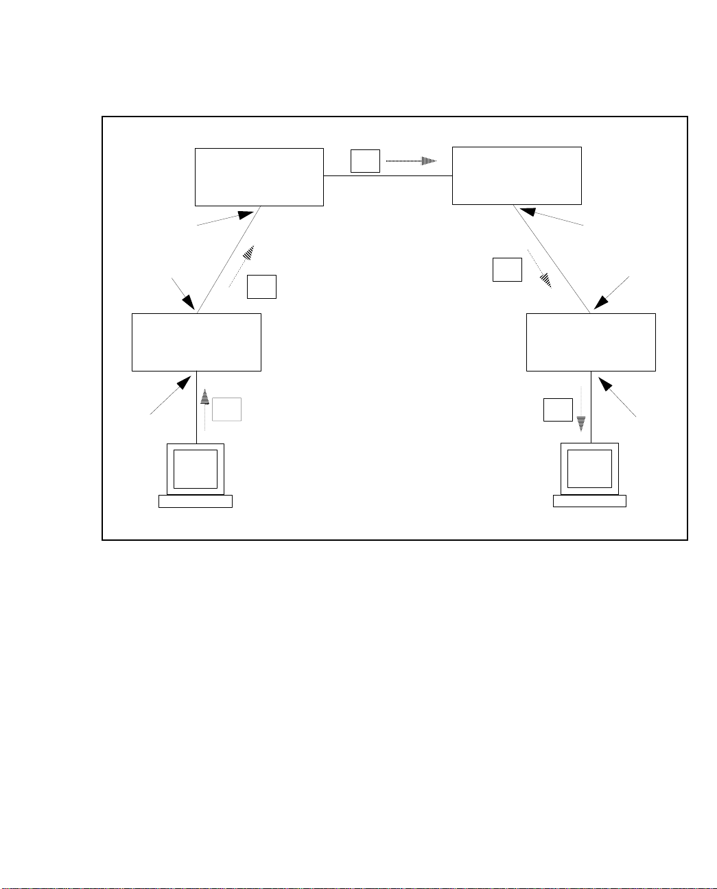
Each ATM cell contains a virtual path identifier (VPI) and a virtual channel identifier (VCI) as
part of its five-byte ATM header. The VPI and VCI are used to route the cell through the ATM
network. When a switch fabric receives a cell, it examines the ATM header to determine the
correct output port, VPI, and VCI for the cell. For example, an ATM switch fabric can be configured such that any cell received on port A1 with VPI|VCI = 0|32 is switched to port B2
with VPI|VCI = 0|35. The translation from input po rt, VP I, and V CI to o utput port, VP I, and
VCI is achieved via a mapping table in the switch fabric’s memory.
The VCI value of cells does not change as the cell is switched through the ATM network via a
virtual path. In a single switch environment, a cell’s VPI and VCI are translated only once, but
in a multiple switch environment a cell’s VPI and VCI are translated many times. It is important to remember that a cell’s VPI and VCI are of local significance only (i.e., link-by-link). It is
also important to note that virtual con necti ons are unidirectional; that is, they are valid in one
direction only. The VPI and VCI may change as the cell is switched through the network.
Configuring PVCs
ForeRunner
ATM Switch Network Configuration Manual
1 - 1
Page 32
Configuring PVCs
VPI: 1, VCI: 37
port C1
port A4
ForeRunner
Switch A
port C1
Workstation P
ForeRunner
Switch B
ATM
cell
ForeRunner
Switch C
ATM
port B 4 port D1
VPI: 2, VCI: 33
cell
cell VPI: 1, VCI: 35
ATM
cell VPI: 0, VCI: 32 VPI: 0, VCI: 36 cell
port B1
ForeRunner
Switch D
Workstation Q
port A1
ATM
port B3
Figure 1.1 - The Cell
The mappings in an ATM network used to route cells from a source to a destination are generally referred to as virtual channels and virtual paths . The f ollo wing s ection s is to expla in how
to create the necessary mappings to establish these virtual paths and virtual channels in a network of ForeRunner ATM switches.
1 - 2
ForeRunner
ATM Switch Network Configuration Manual
Page 33
Configuring PVCs
1.2 Virtual Paths
Virtual paths, which are carried within a physical transit medium (e.g., DS1, E1, DS3, E3,
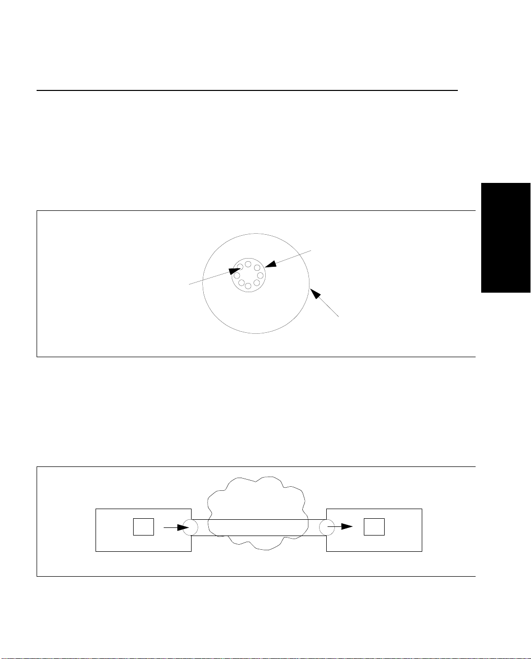
OC3c, or OC12c link), are used to establish connections between two nodes in an ATM network. Many virtual paths can be transmitted within a single physical link. Two types of virtual paths exist: virtual path connections (VPCs), also known as through paths, and
originating/terminating paths, also known as virtual path terminators (VPTs). VPCs allow
virtual paths to be cross-connected at a switch node while VPTs allow virtual channels (VCCs)
to be cross-connected or switched at a switch node.
Virtual
Path
Virtual
Channels
Medium
Configuring PVCs
Figure 1.2 -
A single virtual path ca n be used to route ma ny virtual cha nnels through the ATM network.
Because a virtual path simply routes virtual channels through the network, a cell is guara nteed to have the same VCI when it exits the virtual path as it had when it entered the virtual
path.
ForeRunner
ForeRunner
VPI: X, VCI: Y
ATM Switch Network Configuration Manual
ATM Switch
cell cell
Figure 1.3 -
Virtual Channels in a Virtual Path
ATM
Network
An Example of a Virtual Path
ForeRunner
VPI: Z, VCI: Y
ATM Switch
1 - 3
Page 34
Configuring PVCs
The VCI value of cells does not change as the cell is switched through the ATM network via a
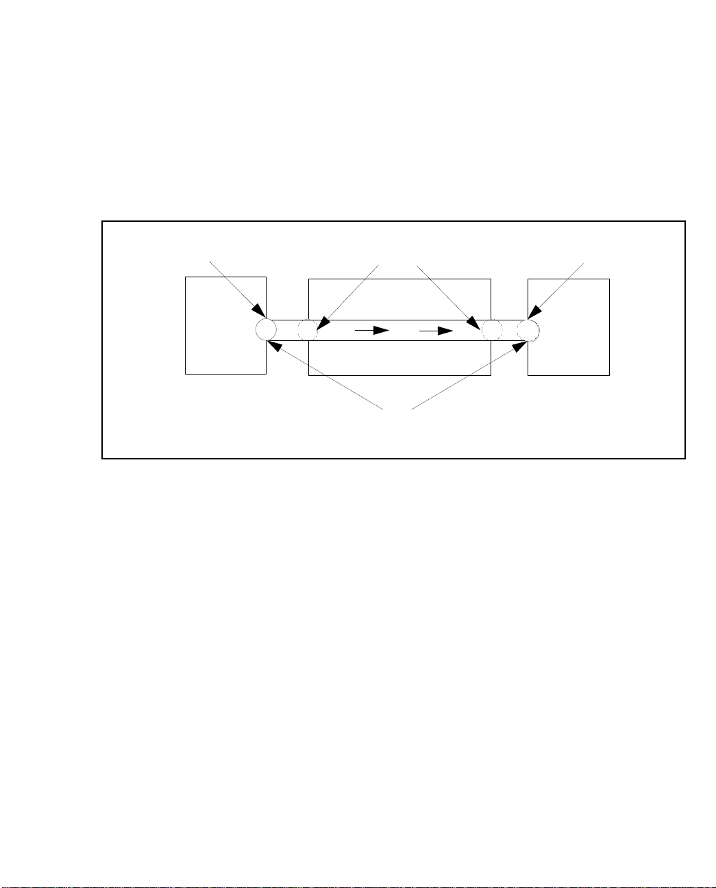
virtual path. Each virtual path mu st originate at a switch fabric, pass through zero or more
switch fabrics and terminate at another switch fabric. The originati on and terminatio n points
are referred to as originating and terminating paths. Virtual paths are switched through switch
fabrics via through paths. Virtual paths are made up of an originating path, zero or more
through paths, and a terminating path.
Originating Path
Through Path
Terminating Path
ForeRunner
ATM Switch
ForeRunner
ATM Switch
Virtual Path
Figure 1.4 - Composition of a Virtual Path
ForeRunner
ATM Switch
1.2.1 Through Paths
Through paths route an entire virtual path through an ATM switch fabric. When a cell is
received by a switch fabric on a through path, the VPI is examined to determine the output
port and VPI. The VCI component of the ATM header remains unchanged and can have any
value. So, all of the channels within the through path are switched correctly without altering
the VCI value of cells on these channels.
Four parameters are needed to define a through path on a ForeRunner switch fabric: input
port, input VPI, output port, and output VPI. Through paths are represented as follows:
<iport> <ivpi> <oport> <ovpi>
The VCI value remains unchanged when cells are switched via a through path. For example,
the through path A4|10 -> B4|20 maps cells received on port A4 with VPI: 10 and any VCI to
port B4 with VPI: 20 and the same VCI.
1 - 4
ForeRunner
ATM Switch Network Configuration Manual
Page 35
Configuring PVCs
switch fabric
B4
cell
VPI: 20
VCI: X
cell
VPI: 10
VCI: X
A4
Through Path
A4|10 -> B4|20
Figure 1.5 -
An Example of a Through Path
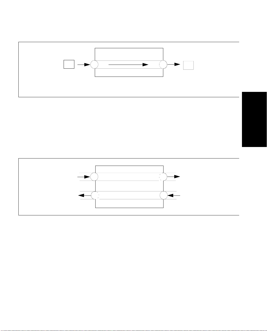
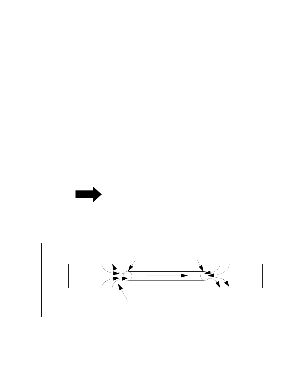
By definition, through paths only switch cells in one direction; they are unidirectional. For
example, switch fabric X is configured with the through path B1|20 -> C1|20. If a cell is
received on port C1 with VPI: 20, it is not transmitted on port B1 with a new VPI: 20. In order
for this to happen, the through path C1|20 -> B1|20 must exist as well. Since through paths
are unidirectional, two through paths are necessary for bidirectional communication.
B1|20 -> C1|20
B1 C1
C1|20 -> B1|20
Configuring PVCs
ForeRunner
Figure 1.6 -
ATM Switch Network Configuration Manual
Through Paths are Unidirectional
1 - 5
Page 36
Configuring PVCs
1.2.2 Originating and Terminating Paths
As previously noted, originating and terminating paths (also called virtual path terminators)
are points at which a virtual path originates and terminates. For example, if a virtual path
exists from switch fabric A to switch fabric B, then there must be an originating path on switch
fabric A and a terminating path on switch fabric B.
An originating path is defined by two parameters: output VPI and output port. Similarly, a
terminating path is defined by the parameters: input VPI and input port. Because originating
and terminating paths do not define the way cells are switched through an A TM switch fabric,
virtual channels must exist to switch cells from a terminating path to an originating path. (See
the section about virtual channels for more information .) Originating and terminating paths
are the endpoints of virtual paths and are used primarily for bandwidth allocation.
The bandwidth allocated to originating and terminating paths is used to control the amount of
virtual channel (VCC) bandwidth entering or leaving a virtual path. The total guaranteed
bandwidth used by virtual channels on an originating path or a terminating path cannot
exceed the amount of bandwidth allocated to that path. For example, as illustrated in
Figure 1.7, if each of the four virtual channels shown is using 10 Mbps of bandwidth, then the
originating and terminating paths must h ave at lea st 40 Mbps of bandwidth allocated.
UBR traffic bandwidth, which is a “best effort”
NOTE
service class, is not limited by the VP’s al located
bandwidth since its bandwidth is not
guaranteed. Actual UBR VCC traffic transmitted
within a VP may exceed the VP’s allocated
bandwidth.
1 - 6
ForeRunner
ATM Switch
Figure 1.7 -
Terminating PathOriginating Path
ForeRunner
ATM Switch
Virtual Channels
Using Originating and Terminating Paths for Bandwidth Allocation
ForeRunner
ATM Switch Network Configuration Manual
Page 37

Configuring PVCs
1.3 Listing Virtual Paths
1.3.1 Listing Through Paths
By logging in to AMI (see Chapter 1 of the ATM Management Interface (AMI) Manual for infor-
mation about logging into AMI), it is possible to display either all of the existing through
paths on an individual switch fabric or all of the existing through paths on a specified port. To
list all of the existing through paths on an individual switch fabric, enter the following:
configuration vpc show
Input Output
Port VPI Port VPI UPC Prot Name
3B1 40 3B4 40 0 pvc customer_a
3B1 75 3B5 75 0 pvc customer_b
3B2 95 3B3 95 0 pvc customer_e
3B6 62 3B2 62 0 pvc customer_c
3B6 68 3B3 68 0 pvc customer_d
The fields in this display are defined as follows:
Configuring PVCs
Field Description
Input Port The incoming p ort number of the through path.
Input VPI The incoming virtual path number.
Output Port The outgoing port number of the through path.
Output VPI The outgoing virtual path number.
UPC The integer index that refers to a specific UPC traffic con tract assigned to this through
Prot The type of protocol running on this channel.
Name The user-assigned name which helps to identify this through path uniquely.
ForeRunner
ATM Switch Network Configuration Manual
path. UPC co nt racts can be displ ay e d using
conf upc show
.
1 - 7
Page 38

Configuring PVCs
To list advanced options about all of the existing virtual (through) paths, en ter the following
parameters:
configuration vpc show advanced
Input Output
Port VPI Port VPI Shape ConType
3B1 40 3B4 40 N/A
3B1 75 3B5 75 N/A
3B2 95 3B3 95 tran-tran-pmp
3B6 62 3B2 62 tran-tran-pp
3B6 68 3B3 68 N/A
The fields in the advanced display are defined as follows:
Field Description
Input Port The incoming p ort number of the through path.
Input VPI The incoming virtual path number.
Output Port The outgoing port number of the through path.
Output VPI The outgoing virtual path number.
Shape Indicates whether or not traffic shapin g has been enabled for t his path. This field only
ConType The connecti on type for the endpoint s of this path with respect to a parti cular network.
applies to the Series C network modules.
Orig
(originating) means that the in gress/egress endpoin t of the path is con necte d to the
source node which is outside the network,
endpoint of the p ath is conne cted to a node within the net work, and
means that the ingress/egress endpoint of the path is connected to the destination node
which is outside the ne twork. pp means this is labelled as a point-to-point path,
means this is labelled as a point-to-multipoint path,
point-to-point path.
mpmp
means this is labe lled as a multipo in t-to-multipoint path.
tran
(transit) means that the i ngress/egress
mpp
means this is labelled as a multi-
term
(terminating)
pmp
1 - 8
ForeRunner
ATM Switch Network Configuration Manual
Page 39

Configuring PVCs
1.3.2 Listing Originating and Terminating Paths
By logging in to AMI, it is possible to display either a ll of the existing origina ting and terminating paths on an individual switch fabric or on a specif ied port. To list all of the originating
and terminating paths on an individual switch fabric, enter the following parameters:
configuration vpt show
Input Output
Port VPI Port VPI ResBW CurBW MinVCI MaxVCI VCs Protocol
1C1 0 terminate N/A 0.8K 1 511 6 pvc
1C1 1 terminate 1.0M 0.8K 1 511 2 pvc
1C2 0 terminate N/A 0.8K 1 511 6 pvc
1C3 0 terminate N/A 0.8K 1 511 6 pvc
1C4 0 terminate N/A 0.8K 1 511 6 pvc
1CTL 0 terminate N/A 7.6K 1 1023 24 pvc
originate 1C1 0 N/A 0.8K 1 511 6 pvc
originate 1C1 1 1.0M 0.8K 1 511 2 pvc
originate 1C2 0 N/A 0.8K 1 511 6 pvc
originate 1C3 0 N/A 0.8K 1 511 6 pvc
originate 1C4 0 N/A 0.8K 1 511 6 pvc
originate 1CTL 0 N/A 7.6K 1 1023 30 pvc
Configuring PVCs
The fields in this display are defined as follows:
Field Description
Input Port The incoming port number of th e vp t. Shows
Input VPI The incoming virtual path number.
Output Port The outgoing port number of the vpt. Shows the number of the output port of the vpt.
Output VPI The outgoing virtual path number.
ResBW The maximum amount of ban dwidth, in Kbps, t hat is reserved for the v irtual channels
CurBW The amount of bandwidth, in Kbps, being used by the virtual channels using this vpt.
MinVCI The bottom number for the range of VCIs that are reserved for VCCs on this virtual path
MaxVCI The top number fo r the range of VCIs tha t are reserved for VCCs on this virtual path ter-
VCs The number of virtual channels t ha t are currently using thi s vpt.
Protocol The type of protocol running on thi s ch an nel.
ForeRunner
ATM Switch Network Configuration Manual
terminate
Shows
using this vpt. A value of
cate and de-allocat e ba n dwidth for their channe ls from the li nk.
terminator. The default is 1.
minator. The default is
if it is a terminating pa t h .
N/A
indicates that this path is an ela stic path. Elast ic pat hs allo-
511
.
originate
if it is an originating path.
1 - 9
Page 40

Configuring PVCs
To list all of the advanced options about all of the existing virtual path terminato rs, enter the
following parameters:
configuration vpt show advanced
Input Output
Port VPI Port VPI Shape VBROB BuffOB
1C1 0 terminate N/A N/A N/A
1C1 1 terminate N/A N/A N/A
1C2 0 terminate N/A N/A N/A
1C3 0 terminate N/A N/A N/A
1C4 0 terminate N/A N/A N/A
1CTL 0 terminate N/A N/A N/A
originate 1C1 0 port port
originate 1C1 1 100 100
originate 1C2 0 port port
originate 1C3 0 port port
originate 1C4 0 port port
originate 1CTL 0 N/A N/A
The fields in the advanced display are defined as follows:
Field Description
Input Port The incoming port number of th e vp t. Shows
Input VPI The incoming virtual path number.
Output Port The outgoing port number of the vpt. Shows
Output VPI The outgoing virtual path number.
Shape Indicates whether or not traffic shaping has been enabled for this originating vpt. This
VBROB The bandwidth overbooking level assigned to this vpt, specified as a percentage. The
BuffOB The buffer overbooking level assigned to this vpt, specified as a percentage. The default is
field only applies to the Series C network modules.
default is
cause underbooking. Values greater than
elastic path. Since elastic paths derive their overbooking factors from their parent ports,
use
100
underbooking. Values greater than
path. Since elastic paths derive their overbooking factors from their parent ports, use
conf port show
100
, which means that no overb ooking has bee n defined. Values less than
conf port show
, which means th at no overbooking has been defined. Values less than
to display the overbooking value.
100
to display the overbooking value.
originate
terminate
100
denote overbooking.
denote overbooking.
if it is an originating path.
if it is a terminating pat h.
port
means this is an
port
means this is an elastic
100
cause
100
1 - 10
NOTE
For more information about setting overbookin g
parameters (VBROB and BuffOB), see Section
1.5.2.
ForeRunner
ATM Switch Network Configuration Manual
Page 41
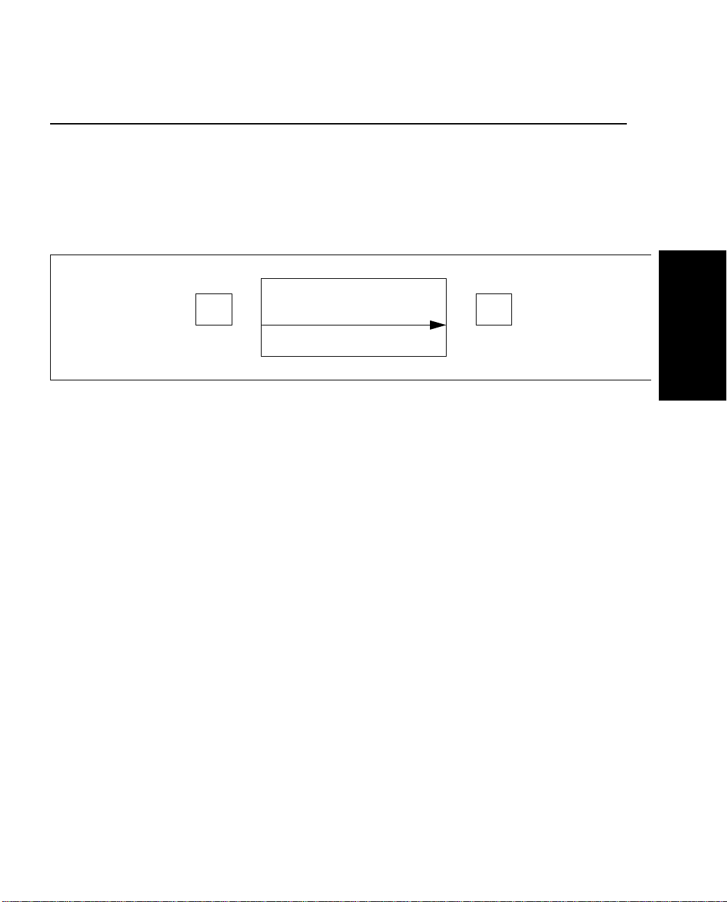
Configuring PVCs
1.4 Virtual Channels
Virtual channels “ride” inside of virtual pa ths. The combina tion of the two specifies a virtua l
connection. On a switch fabric, each virtual channel switches cells with a specific VPI and VCI
received on a specific port to anoth er port with a new VPI and a new VCI. Unlike through
paths, which carry one or more VCCs, virtual channels describe a single virtual connection
between two endpoints.
ForeRunner
cell
ATM Switch
cell
VPI: A, VCI: BVPI: X, VCI: Y
Configuring PVCs
Figure 1.8 -
Six parameters are needed to define a virtual channel: input port, input VPI, input VCI, output port, output VPI, and output VCI. V i rtual chan nels are represented by the fo llowing no tation:
<iport> <ivpi> <ivci> <oport> <ovpi> <ovci>
Virtual channels switch cells using both the VPI a nd VCI values. Both the VPI and VCI values
may change when a cell is switched via a virtual channel. For example, the virtual chann el
C2|1|20 -> D2|9|25 switches cells received on port C2 with VPI: 1 and VCI: 20 such that they
are transmitted out port D2 with VPI: 9 and VCI: 25.
An Example of a Virtual Channel
ForeRunner
ATM Switch Network Configuration Manual
1 - 11
Page 42
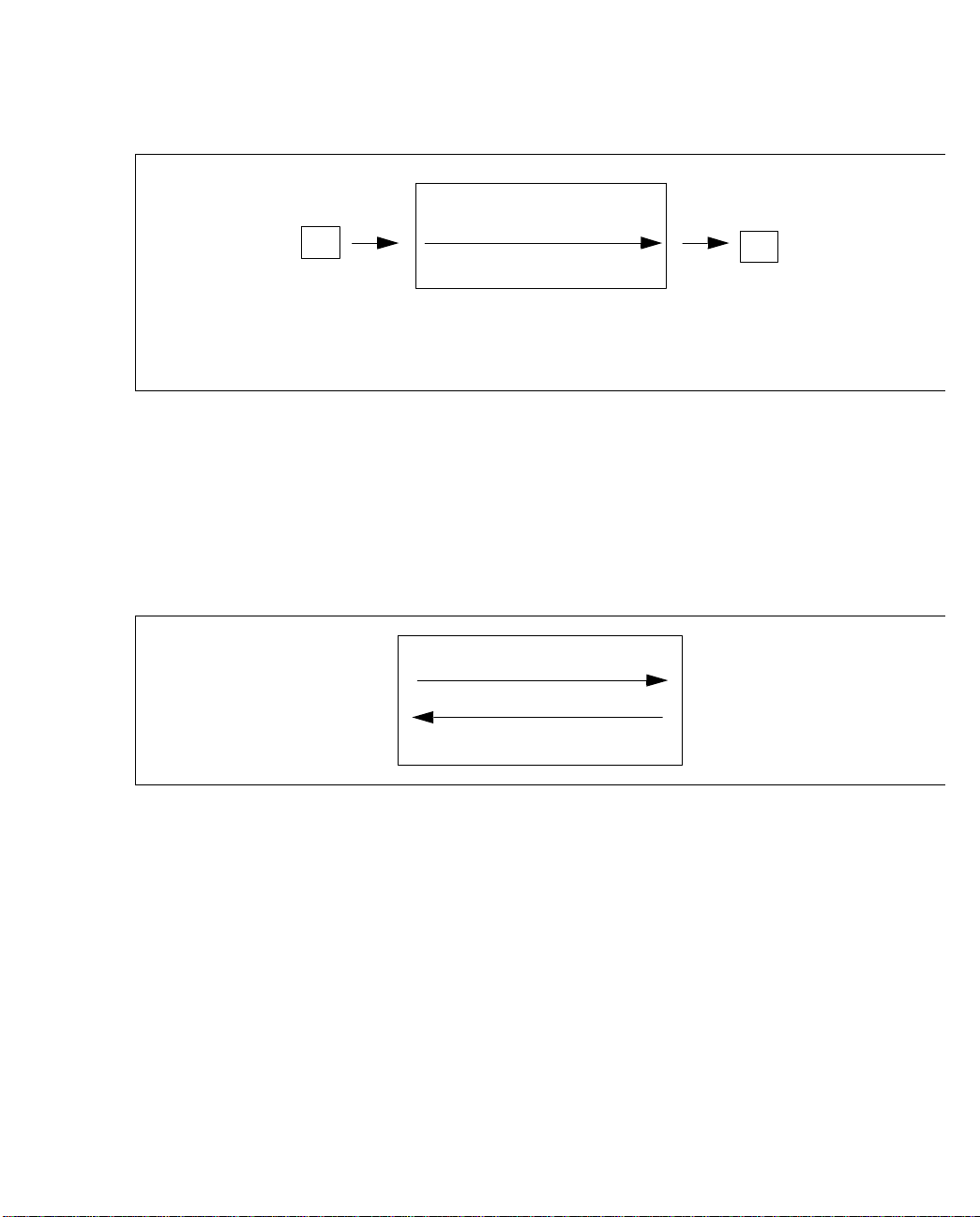
Configuring PVCs
cell
VPI: 1
VCI: 20
C2
switch fabric
D2
cell
VPI: 9
VCI: 25
Virtual Channel
C2|1|20 -> D2|9|25
Figure 1.9 - Example of a Virtual Channel
In order to establish two-way communicatio ns between tw o ports o n a switch fabric, t wo virtual channels are necessary because virtual channels are unidirectional. For example, switch
fabric A is configured with the virtual channel C3|7|12 -> D1|8|2. If a cell is received on port
D1 with VPI: 8 and VCI: 2, it is not transmitted out port C3 with VPI: 7 and VCI: 12. An additional channel, namely D1|8|2 -> C3|7|12, would have to exi st.
C3|7|12 -> D1|8 | 2
C3
D1
D1|8|2 -> C3|7|12
Figure 1.10 - Virtual Channels are Unidirectional
Before a virtual channel can be created, the corresponding terminating and originating paths
must exist. For example, before the channels shown on the switch fabric in Figure 1.11 can be
created, the terminating path C3|3 must exist.
1 - 12
ForeRunner
ATM Switch Network Configuration Manual
Page 43
Configuring PVCs
ForeRunner
Host B
ATM Switch
Switch or
Orig.Term.
Switch or
Host C
C3|3|45 -> A3|9|100
Switch or
Host A
C3|3|50 -> C2|3|98
C3|3|80 -> A1|7|88
Switch or
Host D
C3|3|123 -> A1|3|123
Switch or
Host E
Figure 1.11 -
Virtual Channels Created on Terminating Path C3|3
Similarly, before the virtual channels shown in Figure 1.12 can be created, the originating path
C2|2 must exist.
Switch or
Host A
ForeRunner
ATM Switch
Switch or
Host B
Orig.Term.
A2|7|120 -> C2|2|120
Switch or
Host C
C2|3|67 -> C2|2|37
C3|11|50 -> C2|2|102
Switch or
Host E
B1|2|99 -> C2|2|99
Switch or
Host D
Configuring PVCs
Figure 1.12 -
Virtual Channels Created on Originating Path C2|2
Furthermore, in these examples, the terminating path C3|3 and origin ating path C2|2 must
have enough bandwidth allocated to support the total bandwidth used by the virtual channels
(see Figure 1.7).
ForeRunner
ATM Switch Network Configuration Manual
1 - 13
Page 44

Configuring PVCs
1.4.1 Smart Permanent Virtual Circuits
Smart Permanent Virtual Circuits (SPVCs) are connections that go across multiple swi tch fabrics. An SPVC looks like a PVC at the l ocal and remote endpoints w ith an SVC (Switch ed Virtual Circuit) in the middle. SVCs are channels established on demand by network sign alling.
Similar to a dialed telephone call, SVCs transport information between two locations and last
only for the duration of the transfer.
SPVCs are more robust than PVCs. If a link carrying a PVC goes down, then the PVC goes
down. If a link carrying a SPVC goes down an d there is an alternate route, then the end switch
fabrics of the SPVC automatically reroute the SPVC around the failed link.
As shown in Figure 1.13, interswitch links exist between the ForeRunner switches. The endpoints exist at switch A and switch E. I f a link goes dow n between switch A and swi tch B, an
SPVC can reroute the cell (via an SVC) through switch C.
ForeRunner
cell VPI: 1, VCI: 35
port A4
ForeRunner
Switch
A
Switch
B
Figure 1.13 -
ForeRunner
ForeRunner
The Path of a Cell Via SPVCs
Switch
C
Switch
D
ForeRunner
VPI: 2, VCI: 33
port A1
Switch
E
SVCs
Interswitch Links
cell
1 - 14
ForeRunner
ATM Switch Network Configuration Manual
Page 45

Configuring PVCs
1.4.2 Listing Virtual Channels
By logging in to AMI, you can display either all of the existing virtual channels on an individual switch fabric or on a specified port. To list all of the virtual channels on an individua l
switch fabric, enter the following parameters:
configuration vcc show
Input Output
Port VPI VCI Port VPI VCI UPC Protocol Name
3B1 0 5 3CTL 0 49 0 uni N/A
3B1 0 14 3CTL 0 48 0 spans N/A
3B1 0 15 3CTL 0 47 spans N/A
3B1 0 16 3CTL 0 50 uni N/A
3B1 0 100 3B4 0 100 0 pvc N/A
3B2 0 5 3CTL 0 53 0 uni N/A
3B2 0 14 3CTL 0 52 0 spans N/A
3B2 0 15 3CTL 0 51 spans N/A
Configuring PVCs
Press return for more, q to quit:
q
The fields in this display are defined as follows:
Field Description
Input Port The incoming port number of th e virtual channel.
Input VPI The incoming virtual path number.
Input VCI The incoming virtual channel number.
Output Port The outgoing port number of the virtual channel.
Output VPI The outgoing virtual path number.
Output VCI The outgoing virtual channel number.
UPC The integer index that ref ers to the spec if i c UPC traffic contract assigned to this VCI.
Protocol Indica tes what typ e of channel this is. Can be
routing control channel (0, 18) on PNNI links ov er which PNN I exchanges routing info rmation.
Name The uniqu e, user-assign e d na me for this channel. If no name is assign e d , shows
spans, pvc, uni, spvc
, or
rcc
. rcc is the
N/A
.
ForeRunner
ATM Switch Network Configuration Manual
1 - 15
Page 46

Configuring PVCs
To list advanced information about all of the exist ing perma nent virtual ch annels on a s witch
board, enter the following parameters:
configuration vcc show advanced
Input Output
Port VPI VCI Port VPI VCI Protocol ConType
3B1 0 5 3CTL 0 49 uni N/A
3B1 0 14 3CTL 0 48 spans N/A
3B1 0 15 3CTL 0 47 spans N/A
3B1 0 16 3CTL 0 50 uni N/A
3B1 0 100 3B4 0 100 pvc tran-tran-pp
3B2 0 5 3CTL 0 53 uni N/A
3B2 0 14 3CTL 0 52 spans N/A
3B2 0 15 3CTL 0 51 spans N/A
3B2 0 16 3CTL 0 54 uni N/A
Press return for more, q to quit:
q
The fields in the advanced display are defined as follows:
Field Description
Input Port The incoming port number of th e virtual channel.
Input VPI The incoming virtual path number.
Input VCI The incoming virtual channel number.
Output Port The outgoing port number of the virtual channel.
Output VPI The outgoing virtual path number.
Output VCI The outgoing virtual channel number.
Protocol Indica tes what typ e of channel this is. Can be
ConType The connection type for the endpoints of this channel with respect to a particular network.
routing control channel (0, 18) on PNNI links ov er which PNN I exchanges routing info rmation.
Orig
(originating) mean s that the ing ress/egress endpoint of t he channel is connect ed to
the source node which is outside the network,
egress endpoint of the channel is connected to a node within the network, and
minating) means that the ingress/egress endpoint of the channel is connected to the destination node which is outside the network. pp means this is labelled as a point-to -point
channel,
labelled as a m ultipoint -to-point channel.
multipoint channel.
pmp
means this is l abelled as a point-to- multipoint chan nel,
spans, pvc, uni, spvc
tran
(transit) means that the ingress/
mpmp
means this is lab elled as a m ultipoin t-to-
rcc
, or
mpp
means this is
. rcc is the
term
(ter-
1 - 16
ForeRunner
ATM Switch Network Configuration Manual
Page 47
Configuring PVCs
1.5 Creating PVCs and SPVCs
FORE’s ATM network modules provide ATM transmission connectivity, while its intelligent
network modules, such as the Circuit Emulation Services (CES) network module, provide
adaptation for ports carrying one transmission format (e.g., TDM) to ATM cells. This section
describes how to create the following from one ATM port to another:
• a permanent virtual path (through path)
• a permanent virtual path terminator (originating or terminating path)
• a permanent virtual channel through the network
• a smart permanent virtual channel through the network
This section assumes that the physical port parameters of the switches have already been configured and that the ATM network module traffic models have been set appropriately. For
more information about these configurations, see the ATM Management Interface (AMI)
Manual.
When these paths and channels are created, a
NOTE
command is entered automatically into the
current configuration database (CDB), meaning
that these paths and channels are created every
time the switch control processor (SCP) is
restarted. The CDB should be backed up
frequently.
Configuring PVCs
ForeRunner
ATM Switch Network Configuration Manual
1 - 17
Page 48

Configuring PVCs
1.5.1 Creating a Through Path
To create a new through path, log in to AMI and enter the following parameters:
conf vpc new
<iport> <ivpi> <oport> <ovpi>
[-name
<name>
]
[-upc
<index>
]
The optional parameters for call records and VP shaping (using Series C network modules)
are as follows:
[-inctype (orig | tran | term) -outctype (orig | tran | term)
<vpi>
[pmp |mpp | mpmp]]\-shapeivpi
]
These parameters are defined as follows:
Parameter Description
iport The incoming port numb e r.
ivpi The incoming virtual path number.
oport The outgoing port number.
ovpi The outgoing virtu al p at h number.
-upc <index> The integer index that refers to a specific UPC traffic contract. If no index is specified, then
no traffic policing will take place on this VPI. It is assigned a UPC index of 0, and all traffic
on this VPI is treated as UBR traffic. This is the default.
-name <name> The name you want to assign to this through path to help identify it uniquely. It is most
useful for billing purposes so you can identify which paths are being used by which customers. Can be up to 32 ASCII characters long.
-inctype (orig | tran |term) The path connection type for the incoming path. For billing purposes, it denotes on which
switch this path is arr ivi ng.
is connected to the source node which is outside the network,
the ingress endpoint of the path is connected to a node within the network, and
minating) means that the ingress endpoi nt of the path is connect ed to the destin atio n node
which is outside the network.
-outctype(orig | tran |term) The path connection type for the outgoing path. For billing purposes, it denotes on which
switch this path is leaving.
is connected to the source node which is outside the network,
the egress endpoint of the path is connected to a node within the network, and
minating) means that the egress endpoint of the path is connected to the destination node
which is outside the network.
1
pmp
mpp Indicates this is a multipoint-to-point path.
mpmp Indicates this is a multipoint-to-mult ipoint path.
Indicates this is a point-to-multipoint path.
Orig
(originating) means that the ingress endpoint of the path
Orig
(originating) me ans that the egress end point of t he pa th
tran
(transit) means that
tran
(transit) means that
term
term
(ter-
(ter-
1 - 18
ForeRunner
ATM Switch Network Configuration Manual
Page 49
Configuring PVCs
Parameter Description
-shapeivpi <vpi>
1.
By indicating
sarily create the type of path you have specified. If you assign a connection type, but do not assign a
label, the switch assigns a la bel of pp (point-to-point).
2.
If you want to shape traffic on more than two ports on a given Series C network module, it is recommended that you set
the traffic memory model to model number 5 for that network module using
2
pmp, mpp
The incoming VPI for this through path. When the traffic shaping port is not the port connected to the WAN, a through path must be created from the WAN port to the traffic shaping port. Cells arrive from the network at the traffic shaping port with this value equal to
the VPI of the terminating path at the traffic shaping port. This parameter only applies to
the Series C network modules.
mpmp
, or
, you are only assigning a label for record keeping purpo se s. The swi t ch does not neces-
pmp, mpp
conf module traffic c setmodel
, or
mpmp
Terminating and originating paths cannot be
NOTE
created across the intra-fabric ports on an
ASX-1000; only through paths can be created
across the intra-fabric ports as shown in the third
example.
The following is an example of how to create a virtual path which specifies a name:
.
Configuring PVCs
myswitch::configuration vpc> new 3b1 75 3b5 75 -name customer_b
The following is an example of how to create a virtual path which specifies a name and a connection type:
myswitch::configuration vpc> new 3b6 62 3b2 62 -name customer_c -inctype tran
-outctype tran
The following is an example of how to create a virtual path on an ASX-1000. To create a
through path going in port 2A 1, VPI 1 on the switch bo ard installed in slot 2 and going out
port 4B1, VPI 1 on the switch board installed in slot 4, enter the following:
myswitch::configuration vpc> new 2a1 1 2e4 1
myswitch::configuration vpc> new 2e4 1 2a1 1
myswitch::configuration vpc> new 4b1 1 4e2 1
myswitch::configuration vpc> new 4e2 1 4b1 1
ForeRunner
ATM Switch Network Configuration Manual
1 - 19
Page 50

Configuring PVCs
In the first line in the first pair, notice that the output port is 2E4. This is the intra-fabric port.
The 2 means the connection is coming out of the switch board in slot 2 through the intra-fabric
port. The E represents the intra-fabric port. The 4 means the connection is destined for switch
board in slot 4. 2E4 then becomes the input port in the second line.
In the first line in the second pair, notice that the output port is 4E2. This is the intra-fabric
port. The 4 means the connection is coming out of the switch board in slot 4 through the intrafabric port. The E represents the intra-fabric port. The 2 means the connection is destined for
switch board in slot 2. 4E2 then becomes the input port in the second line.
At the same time, a command is entered automatically into the current configuration database, which means that this virtual path is created every time the SCP is restarted.
1 - 20
ForeRunner
ATM Switch Network Configuration Manual
Page 51
Configuring PVCs
1.5.2 Creating an Originating or Terminating Path
To create an originating or terminating path (virtual path terminator), log in to AMI and enter
the following parameters:
configuration vpt new
[-minvci
<port> <vpi>
<vci>
(term | orig) [-reserved <Kbs>]\
] [-maxvci
<vci>
]
The -reserved, -minvci, and -maxvci parameters are optional for creating originating or
terminating paths. The advanced traffic management options for creating originating paths
are as follows:
[-shapeovpi
[-vbrob
<percent>
<vpi>
] [-loopvpi
] [-vbrbuffob
<vpi>
]
<percent>
]
The advanced QoS options for creating originating or terminating paths are as follows:
[-cbr (none | default | <qosindex>)]
[-rtvbr (none | default | <qosindex>)]
[-nrtvbr (none | default | <qosindex>)]
[-ubr (none | default | <qosindex>)]
[-abr (none | default | <qosindex>)]
The
NOTE
<qosindex>
new) before it can be applied to the originating/
must exist (conf qosext
terminating path.
These parameters are defined as follows:
Configuring PVCs
Parameter Description
port The port n u mber for this vpt.
vpi The path number for this vpt.
term Specifies that the vpt to be created is a terminating path.
orig Specifies that the vpt to be created is an originating path.
reserved The a mount of ban dwidth , in K bps, that y ou wa nt to reserv e on this v pt. If this option is
not used, an elastic pat h is created. Elastic paths all ocate and de-allocate bandwidth for
their channels from the link.
minvci The bottom number for the range of VCIs to be reserved for VCCs on this vpt. The default
is 1.
maxvci The top number for the range of VCIs to be reserved for VCCs on this vpt. The default is
ForeRunner
ATM Switch Network Configuration Manual
511
.
1 - 21
Page 52

Configuring PVCs
Parameter Description
shapeovpi The output path on a traffic shaping originating vpt. Setting this value configures traffic
loopvpi The originatin g vp i will be shaped by a through path goi ng to a Series D network module.
vbrob The bandwidth over booki ng lev el for this vpt, specif ied as a perce ntag e. Valid values are
vbrbuffob The buffer overbooking level for this vpt, specified as a percentage. Valid values are inte-
none The specified cla ss of service (CB R, real-time VBR, n on real-time VBR, UBR, ABR) is n ot
default The default parameters of 0 CTD, 0 CDV, and 0 CLR are to be used for the CBR class of service.
qosindex The index of the se t o f QoS extension parameters. See
shaping on the originating path. Cells bound for the network leave the traffic shaping port
with this VPI. When the traffic shaping port is the WAN port, this value equals the input
VPI of the origin ating path. If the traffic shaping port is not the WAN port, this value
equals the input VPI of the through path from the shaping port to the WAN port. This
parameter only applies to t he Seri e s C network modules. See Section 1.5.2.1.
You should enter the input vpi of the through path that goes from the looping port to the
WAN port. This option is also us ed w hen c reating the through path that connects from the
WAN port to th e looping por t. The throug h path loopv pi should b e the same vp i as the
terminating path on the looping port. See Section 1.5.2.1 for more information.
integers from 1 to 32,767.
100
than
cannot be specified on an elastic path. Therefore, yo u ca n o nl y s pecify an overbooking factor for an originating path when you also have reserved bandwidth for the path (i.e., specified the
gers greater than or equal to 1.
less than
booking cannot be specified on an elastic path. Therefore, you can only specify an overbooking factor for an originating path when you also have reserved bandwidth for the
path (i.e., specified the
supported.
cause underbooking. Values greater than
-reserved
100
cause underbooking. Va lues greater than
100
Kbs
> parameter).
<
-reserved
means that n o overbooking has been defined. Values less
100
means that no overbook ing has been defi ned. Values
Kbs
> parameter).
<
100
cause overbooking. Overbooking
100
cause overbooking. Over-
conf qosext show
for this number .
1 - 22
NOTE
Bandwidth and/or buffer overbooking are used
when the number of VBR VCCs configured
across an originating or terminating VPT exceeds
the guaranteed capacity of the VP. While
overbooking removes service guarantees (in the
case when all users transm it at full contract rate
simultaneously), a network can be engineered in
a more cost-effective manner if it is assumed that
all VCC sources do not transmit simultaneously.
Guideline:
An initial buffer overbooking value of
500-700% is recommended until live traffic
patterns and VPC utilization can be measured. If
bandwidth is still under-utilized, a higher
VBROB setting can be used.
ForeRunner
ATM Switch Network Configuration Manual
Page 53
The following is an example of how to create a terminating path:
myswitch::configuration vpt> new 3b3 99 term
Would you like to create the originating side also [y]? y
The following is an example of how to create a originating path:
myswitch::configuration vpt> new 3b4 88 orig
Would you like to create the terminating side also [y]? y
The following is an example of how to delete a terminating path:
myswitch::configuration vpt> del 3b4 88 term
Would you like to delete the originating side also [y]? y
The following is an example of how to delete an originating path:
myswitch::configuration vpt> del 3b3 99 orig
Would you like to delete the terminating side also [y]? y
Configuring PVCs
Configuring PVCs
If you do not specify
myswitch::configuration vpt> del 3b4 88
NOTE
ForeRunner
ATM Switch Network Configuration Manual
term
or
, the switch automatically deletes both sides of the path:
orig
Before deleting a virtual path, you must first
delete all VCCs which use that path.
1 - 23
Page 54
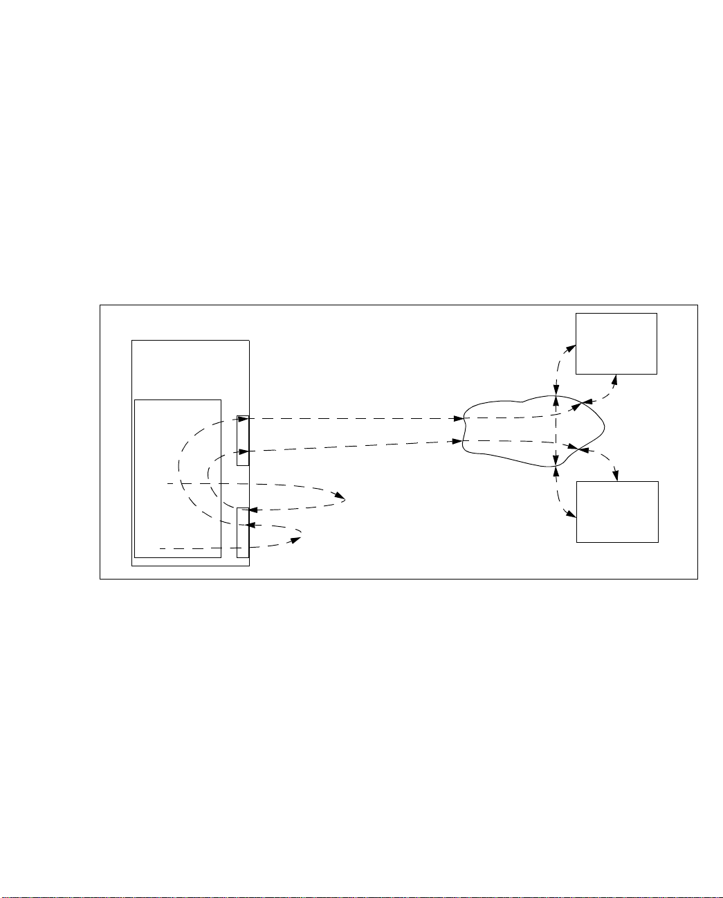
Configuring PVCs
1.5.2.1 Shaping Multiple Originating Paths on a Single Port
This feature allows you to sh ape several or iginating pa ths to be out put on a si ngle port. Thi s
feature is useful if you have several remote sites int erconnected by a PVP mesh. If you only
need to shape one originating path, you can simply use the conf port traffic d
ratelimit command on a Series D network module.
This feature requires the use of two ports. One port, which can be on a Series C, Series LC, or
Series D network module, is used for o riginating and termin ating path(s). This port is put in
either physical or diagnostic loopback and is configured with the new option -loopvpi
under conf vpt new. The other port provides the actual output on a shaped through path, so
this port must be on a Series D network module.
Switch A
VP 0
switch fabric
VP 1
Figure 1.14 -
VP 3
shaping port
1A1
VP 2
VP 2
1A2
looping port (orig. and term. paths VP 0 and VP 1)
VP 3
WAN PVP Mesh
PVPs Looped through Port 1A2 and Output on Port 1A1 to WAN
Switch B
Switch C
As shown in the example in Figure 1.14, the traffic that is going out originating path 0 on port
1A2 gets looped so th at it is output to the WAN on through path 2 on shaping port 1A1. Similarly, the traffic that is going out originating path 1 on port 1A2 get s looped so that it is output
to the WAN on through path 3 on shaping port 1A1.
1 - 24
ForeRunner
ATM Switch Network Configuration Manual
Page 55
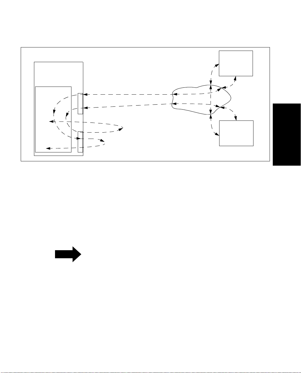
Configuring PVCs
Switch A
VP 0
switch fabric
VP 1
Figure 1.15 -
VP 3
shaping port
1A1
VP 2
VP 0
1A2
looping port (orig. and term. paths VP 0 and VP 1)
VP 1
WAN PVP Mesh
PVPs Coming in Port 1A1 from WAN and Looped through Port 1A2
Switch B
Switch C
Then, as shown in the example in Figure 1.15, the traffic that is coming in through path 2 on
port 1A1 from the WAN gets looped back to terminating path 0 on on port 1A2. Similarly, the
traffic that is coming in through path 3 o n port 1A 1 from the WAN gets looped back to terminating path 1 on port 1A2.
In your own network, yo u w ill repeat this process on these sam e tw o ports for a s many pa ths
as you want to shape.
Configuring PVCs
ForeRunner
Before you configure the paths, you should
NOTE
configure the network module that will co ntain
the looping port to maximize the number of
multicast connections. On a Series C network
module, use model number 5 under conf
module traffic c setmodel. On a Series LC
network module, use model number 6, 7, or 8
under conf module traffic lc setmodel.
ATM Switch Network Configuration Manual
1 - 25
Page 56
Configuring PVCs
To configure the shaped originating paths as shown in the example in Figure 1.14 and
Figure 1.15, perform the following steps:
1. First, create the UPC contract to be used on the through paths that are going to be
output on the shaping port on the Series D network module to the WA N.
myswitch::configuration upc> new 2 cbr 42452 noGCRA -scheduling smoothed
NOTE
You must use the
-noGCRA
policing. This allow bursts without dropping
option to disable
cells. The shaped rate is equal to PCR for CBR
traffic and equal to SCR for VBR traffic. You must
also use the
smoothed
scheduling option so that
a rate group is created when a PVC or PVP is
configured with this UPC.
2. Next, delete any existing path(s) on the looping port as follows:
myswitch::configuration upc> conf vpt
myswitch::configuration vpt> conf vpt del 1a2 0
By default, path 0 is the only path that exists. If
NOTE
3. Recreate the paths on the looping port using the
path 1 already exists, you must delete it using
the command
conf vpt del 1a2 1
-loopvpi
option to ensure that
cells from the WA N port get looped back into the terminating path.
myswitch::configuration vpt> new 1a2 0 -loopvpi 2
myswitch::configuration vpt> new 1a2 1 -loopvpi 3
.
1 - 26
4. Crea te a PVP to the shaping port on a Series D network module and apply the UPC
contract that you created in step 1 so that it shapes the cells.
myswitch::configuration vpt> conf vpc
myswitch::configuration vpc> new 1a2 2 1a1 2 -upc 2
myswitch::configuration vpc> new 1a2 3 1a1 3 -upc 2
ForeRunner
ATM Switch Network Configuration Manual
Page 57
Configuring PVCs
5. Create a PVP in the opposite direction and use -loopvpi to ensure that the cells
on each through path get looped back the terminating paths on the looping port
(1a2).
myswitch::configuration vpc>
myswitch::configuration vpc>
new 1a1 2 1a2 2 -loopvpi 0
new 1a1 3 1a2 3 -loopvpi 1
6. Now use a loopback command to loop the transmit side to the receive side on the
looping port (1a2).
myswitch::configuration vpt>
myswitch::configuration vpt>
conf port admin 1a2 down
conf port sonet loop 1a2 diag
Any required signalling paths must be recreated
NOTE
at this point.
7. Additional shaped originating paths can be added later on these same two ports
as needed by repeating the steps in this section.
1.5.2.2 Terminating a PVC at a Switch
Sometimes it is necessary to create a PVC between a host and a switch fabric that is at a remote
location. In this case, the PVC should be created from the host to the control port (CTL) of the
switch and vice versa.
Some additional configuration is necessary for commun ication to be established between the
host and the switch fabric. The switch needs an entry in its ATM ARP cache in order to send
cells destined for the host with the correct VPI and VCI and to pass received cells with a specific VPI and VCI to IP. This configuration can be done using A MI as sh own in the fol lowing
subsections. (See the
atmarp (8c)
man page for more information.)
Configuring PVCs
ForeRunner
ATM Switch Network Configuration Manual
1 - 27
Page 58

Configuring PVCs
1.5.2.3 Creating ATM ARP Entries
To create a FORE IP PVC ARP entry, log in to AMI. Data on this PVC is encapsulated using
null encapsulation (also known as VC-based multiplexing) as specified in RFC-1483. Enter the
following parameters:
configuration atmarp newforeip
<host> <vpi> <vci>
(4|5) [
<interface>
These parameters are defined as follows:
Parameter Description
host The IP address of the remote host.
vpi The virtual path number of the FORE IP PVC. Must be 0.
vci The virtual channel number of the FORE IP PVC.
4 | 5 The connection’s ATM Adaptation Layer (AAL) type. The default is 4.
interface The FORE IP in terface to be used for this conn e ct ion. The default is asx0.
Once the parameters are entered, the entry is created instantly by the SCP. At the same time, a
command is entered automatically into th e current CDB which creates this ATM ARP entry
each time the SCP is restarted.
To create a new Classical IP PVC ARP entry, log in to AMI. All data is sent LLC/SNAP encapsulated. Enter the following parameters:
configuration atmarp newclassicalip
<host> <vpi> <vci> [<interface>
]
These parameters are defined as follows:
Parameter Description
host The host IP address of the remote IP endstation.
vpi The virtual path number of the Classical IP PVC.
vci The virtual channel number of the Classical IP PVC.
interface The Clas sical IP interface t o be used for thi s connection: qaa0 , qaa1, qaa2, or q aa3.
The default is qaa0.
]
Once the parameters are entered, the Classical IP PVC ARP entry is created instantly by the
SCP. At the same time, a command is entered automatically into the current CDB which creates this ATM ARP entry each time that the SCP is restarted.
1 - 28
ForeRunner
ATM Switch Network Configuration Manual
Page 59

Configuring PVCs
1.5.2.4 Listing ATM ARP Entries
To verify that the ARP entries exist correctly for the outgoing PVC connection from the SCP to
the host, display the ATM ARP cache by logging in to AMI and entering the following parameters:
configuration atmarp show
IPaddress If VPI VCI AAL Type Direction
198.29.22.9 asx0 0 63 aal5 foreIpSVC pending
198.29.22.15 asx0 0 231 aal5 foreIpSVC pending
198.29.22.37 asx0 0 65 aal34 foreIpSVC pending
IPaddress If NSAP Address
198.29.17.3 qaa0 0x47.0005.80.ffe100.0000.f21b.0138.002048102754.00
198.29.17.10 qaa0 0x47.0005.80.ffe100.0000.f21b.0137.002048100be6.00
198.29.17.15 qaa0 0x47.0005.80.ffe100.0000.f21b.0137.00204810048d.00
198.29.17.52 qaa0 0x47.0005.80.ffe100.0000.f21b.0138.0020481b0138.00
The fields in this display are defined as follows:
Field Description
IPaddress The IP add ress for this c onnection.
If The name of the IP interface for this connection.
VPI The virtual path number.
VCI The virtual channel number.
AAL The AAL type of the given connection.
Type Shows what kind of connection this is. Can be
PVC
classicalIpSVC
, or
Direction
NSAP Address The NSAP address for this connection.
Outgoing
connection.
plete
address.
means this is an outgoing connection.
Pending
means that the IP-to-ATM address mapping is not yet known for the given IP
.
means that a connection has not (yet) been established.
foreIpPVC, foreIpSVC, classicalIp-
Incoming
means this is an incoming
Incom-
Configuring PVCs
ForeRunner
ATM Switch Network Configuration Manual
1 - 29
Page 60

Configuring PVCs
1.5.3 Creating a Virtual Channel
To create a new virtual channel, log in to AMI and enter the following parameters:
configuration vcc new
<iport> <ivpi> <ivci> <oport> <ovpi> <ovci>
[-upc
<index>
] [-name
<name>
]
The advanced options for call records are as follows:
-inctype (orig | tran | term) -outctype (orig | tran | term)
[pmp | mpp | mpmp]]
These parameters are defined as follows:
Parameter Description
iport The incoming port numb er.
ivpi The incoming virtual path number.
ivci The incoming virtual channel number.
oport The outgoing port number.
ovpi The outgoing virtu al p at h number.
ovci The outgoing virtual channel number.
-upc <index> The integer index that refers to a specific UPC traffic contract. If no index is specified, then
name The name you want to assign to this chan nel to ident ify it uniq uely. It is useful for billing
inctype The channel connection type for the incoming channel. For billing purposes, it denotes on
outctype The channel connection type for the outgoing channel. For billing purposes, it denotes on
1
pmp
mpp Indicates this is a multipoint-to-point channel.
no traffic policing will take place on this VCI. It is assigned a UPC index of 0, and all traffic
on this VCI is treated as UBR traffic. This is the default.
purposes so you can identify which channels are being used by which customers. Can be
up to 32 ASCII charact e rs long.
which switch this ch ann el i s arriv ing .
of the channel is connected to the source node which is outside the network,
sit) means that the ingress endpoint of the channel is connected to a node within the network, and
to the destination node which is outside the network.
which switch this channel is leaving.
the channel is connected to the source node which is outside the network,
means that the egress endpoint of the channel is connected to a node within the network,
and
destination node which is outs ide the network.
Indicates this is a point-to-multipoint channel.
term
(terminating) means that the ingress endpoint of the channel is connected
term
(terminating) means that the egress endpoint of the channel is connected to the
Orig
(originating) mean s that the in gress end poin t
Orig
(originating) means that the egress endpoint of
tran
tran
(transit)
(tran-
1 - 30
ForeRunner
ATM Switch Network Configuration Manual
Page 61

Configuring PVCs
Parameter Description
mpmp Indicates this is a multipoint-to-mult ipoint channel.
1.
By indicating pmp, mpp, or mpmp, you are only assigning a label for record keeping purpose s. The switch does not necessarily create the type of channel you hav e speci fie d . If you ass ign a connection type, but do not assign a pmp, mpp, or
mpmp label, the switch assigns a label of pp (point-to-point).
The following is an example of how to create a uni-directional virtual channel which specifies
the call record connection type as transit:
localhost::config vcc>
new 3b1 0 100 3b4 0 100 -inctype tran -outctype tran
The following is an example o f how to create a uni-directional virtua l channel which has t he
name “customer_a” assigned to it:
myswitch::configuration vcc>
new 3b2 0 145 3b3 0 145 -name customer_a
The following is an example of how to create a bi-directional virtual channel on an ASX-1000.
To create a VCC going in port 2A1, VPI 0, VCI 100 on the switch board installed in slot 2 and
going out port 4B1, VPI 0, VCI 100 on the switch board installed in slot 4, enter the following:
myswitch::configuration vcc>
myswitch::configuration vcc>
myswitch::configuration vcc>
myswitch::configuration vcc>
new 2a1 0 100 2e4 0 100
new 2e4 0 100 2a1 0 100
new 4b1 0 100 4e2 0 100
new 4e2 0 100 4b1 0 100
In the first line in the first pair, notice that the output port is 2E4. This is the intra-fabric port.
The 2 means the connection is coming out of the switch board in slot 2 through the intra-fabric
port. The E represents the intra-fabric port. The 4 means the connection is destined for switch
board in slot 4. 2E4 then becomes the input port in the second line.
Configuring PVCs
In the first line in the second pair, notice that the output port is 4E2. This is the intra-fabric
port. The 4 means the connection is coming out of the switch board in slot 4 through the intrafabric port. The E represents the intra-fabric port. The 2 means the connection is destined for
switch board in slot 2. 4E2 then becomes the input port in the second line.
Once the parameters are entered, the virtual channel is created instantly by the SCP. At the
same time, a command is entered automatically into the current configuration database,
which means that this virtual channel is created every time the SCP is restarted.
ForeRunner
ATM Switch Network Configuration Manual
1 - 31
Page 62
Configuring PVCs
1.5.4 Creating a SPANS SPVC
To create a SPANS SPVC, you must configure both ends of the connection concurrently on the
two switch fabrics. This means you m ust have an AMI session op en on both the local switch
fabric and the destination switch fabric. To create a new SPANS SPVC, log in to AMI and enter
the following parameters:
myswitch::configuration spvc spans> new
<dest-vpi> <dest-vci>
[-peak
<Kb/sec>
\
] [(source | destination | bidirectional)]
These parameters are defined as follows:
Parameter Description
port The port number on the local switch fabric.
vpi The virtual path number on the local switch fabric.
vci The virtual channel number on the local switch fabric.
dest-session The IP address of the remote switc h .
dest-port The port number on the remote swi tc h fab ri c.
dest-vpi The virtual path number on the remote swi t ch fab ri c.
dest-vci The virtual channel number on the remote switch fabric.
-peak <Kb/sec> The amount of peak bandw idth allocated for this SPANS SPVC, specified in kilobits per
source | destination | bidirecti onal
second. The default is 0.
source
means a unidirection al SPANS SPVC going from the local switch fabric to the
remote switch fab ric will b e created.
going from the remote switch fabric to the local switch fabric will be created.
bidirectional
default direction, if you do not spe ci f y on e , is
<port> <vpi> <vci> <dest-session> <dest-port>
destination
means the pair of unidirectional SPANS SPVCs will be created. The
means a unidirectional SPANS SPVC
bidirectional
.
1 - 32
NOTE
To create a bidirectional SPANS SPVC, you must
either specify bidirectional, or you must set up
two unidirectional SPANS SPVCs with one going
in each direction.
ForeRunner
ATM Switch Network Configuration Manual
Page 63
Configuring PVCs
To create a SPANS SPVC, you need to configure the two ends concurrently on the two switch
fabrics . Therefore, yo u first need to open an AMI session to the destination switch fabric by
using the SCP’s IP address, along with the SNMP read-write community string. The following
example depicts how to create a bidirectional SPVC from the local switch fabric (myswitch) to
a remote switch fabric (198.29.22.46 named fishtank). The asterisk (*) in front of the prompt
indicates that it is a remote session. To return to the local session, you must type localhost
(instead of the prompt name).
myswitch::>
Opening a session for “198.29.22.46”, please wait...
Connected to “198.29.22.46” (asx200bx).
*fishtank::>
myswitch::>
usage: new <port> <vpi> <vci> <dest-session> <dest-port> <dest-vpi>
<dest-vci> \[-peak <Kb/sec>] [(source | destination | bidirectional)]
myswitch::configuration spvc spans>
open 198.29.22.46 private
localhost
configuration spvc spans new ?
new 1c1 0 49 198.29.22.46 1b1 0 50
1.5.5 Displaying SPANS SPVC Information
This command allows you to display all of the S PANS SPVCs on an individua l switch fabric.
Enter the following parameters:
myswitch::configuration spvc spans>
Local Remote
ID Port VPI VCI BW Direction ID Port VPI VCI Switch
35664 1C1 0 51 0.0 bidirectional 10427 1B1 0 52 198.29.22.46
65364 1C1 0 49 0.0 bidirectional 42591 1B1 0 50 198.29.22.46
show
Configuring PVCs
The fields in this display are defined as follows:
Field Description
Local ID T he unique numbe r that the local switch fabr ic’s SCP assign ed to this SPANS SPVC when
Local Port The p ort n u mber on the local switch fabric.
Local VPI The virtual path number on the local switch fa bric.
Local VCI The virtual channel number on the local switch fabric.
ForeRunner
ATM Switch Network Configuration Manual
it was created.
1 - 33
Page 64

Configuring PVCs
Field Description
Local BW The amount of peak bandwidth allocated for this SPANS SPVC, specified in Kbps.
Remote ID The unique number that the remote switch fabric’s SCP assigned to this SPANS SPVC
when it was created.
Remote Port The port number on the remote switch fabric.
Remote VPI The virtual path number on the remo te switch fabric.
Remote VCI The virtual channel number on the remote switch fabric.
Switch The IP address or name of the remote switch fabric’s SCP.
The following is displayed if no SPANS SPVCS have been configured:
myswitch::configuration spvc
No SPVC information is available
spans
> show
1 - 34
ForeRunner
ATM Switch Network Configuration Manual
Page 65
Configuring PVCs
1.6 Traffic Types
The following sections contain informal
NOTE
Quality of Service (QOS) Management is based on the bandwidth parameters associated with
a virtual connection and the class of service and ATM Adaptation Layer (AAL) used for that
connection. In order to support voice, video, and data, the ATM Forum has defined four
classes of service, or traffic types: Constant Bit Ra te (CBR), Variable Bit Rate (VBR), Available
Bit Rate (ABR), and Unspecified Bit Rate (UBR).
• At connection set-up ti me, traffic that uses a CBR parameter, such as a voice signal, makes a request for a dedicated Peak Cell Rate (PCR). Once the PCR is
defined, the ATM network must be able to guarantee that amount of bandwidth
for the duration of the connection.
• At connection set-up time, traffic that uses a VBR parameter, such as a video and
data, makes a request for a dedicated PCR, Sustainable Cell Rate (SCR), and Maximum Burst Size (MBS). Once these cell rates are defined, the ATM network must
be able to guarantee these rates for the duration of the connection.
• At connection set-up time, ABR traffic makes a request for a dedicated PCR and
Minimum Cell Rate (MCR). Once these cell rates are defined, the ATM network
must be able to guarantee the MCR rate for the duration of the connection. ABR
traffic sources adjust their transmission rate in response to information they
receive describing the status of the network and its capability to successfully
deliver data.
• UBR traffic, such as broadcast info rmation and ARP messages, is also known as
“best effort” service. UBR provides no bandwidth guarantees.
definitions of the concepts presented. For a
detailed understanding of these issues, please
see the ATM Forum’s UNI 3.1 and TM 4.0
Specifications.
Configuring PVCs
Because ATM is designed to provide a single network to transport this variety of traffic
classes, FORE’s traffic policing and Connection Admission Control (CAC) schemes are vital to
allowing this mix of traffic to flow smoothly.
ForeRunner
ATM Switch Network Configuration Manual
1 - 35
Page 66

Configuring PVCs
1.7 Traffic Policing (Usage Parameter Control)
Traffic policing, also known as Usage Parameter Control (UPC), is a meth od of ensuring fair
allocation of network resources and of assessing the cells entering the switch for conformance
with pre-established traffic bandwidth contracts. Those cells that exceed the specified contract
are “tagged” or “dropped,” depending on what is defined in the contract. This ensures that
the connections with reserved bandwidth are not exceeding their reservations. FO RE S ystems’
switches use a combination of “leaky bucket,” or Generic Cell Rate Algorithm (GCRA) hardware in the switch fabric and user-configurable parameters in AMI to perform these policing
functions.
1.7.1 Leaky Bucket Algorithm
The first important concept to understand is the leaky bucket algorithm. Leaky buckets are a
mechanism by which cells enterin g the swit ch fabric are monitored for compliance w ith UPC
traffic contracts that have been negotiated at connection set-up time. Before the leaky buckets
are discussed, it is important to understand the parameters that are being measured by the
buckets, as shown in Table 1.1. These parameters are informally defined as follows:
• Peak Cell Rate (PCR) - the maximum number of cells per second
• Cell Delay Variation Tolerance (CDVT) - the tolerance for variation in the interarrival time of these cells, or the amount of jitter that can be accepted by the network
• Sustainable Cell Rate (SCR) - the average rate of cell transm issi on for this connection, taking bursting into account
• Burst Tolerance (BT) - the maximum amount of cells that can be transmitted
• Minimum Cell Rate (MCR) - the minimum rate that the network has to guarantee
for an ABR connection
The leaky bucket algorithm is basically a timer which assesses if cells entering the switch fabric conform to the parameters listed above. As a cell arrives, the timer assesses if the cell is on
time, late, or early. If the cell is determined to be on time or late (based on the traffic parameters), the cell is allowed to pass unchanged. If the cell is early (which, in turn, causes the cell
stream to exceed the specifie d par ameters), the cell is co nsidered non-conforming and is either
dropped or tagged (the CLP bit is set to 1), depending on the specified contract.
The first bucket in this analogy measures the PCR, or the rate at which the bucket drains. It
also considers the CDVT, or the depth of the bucket. The second bucket measures the SCR, or
the rate at which the bucket drains, and the BT, or the depth of the second bucket.
1 - 36
ForeRunner
ATM Switch Network Configuration Manual
Page 67
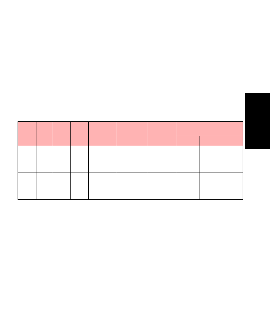
Configuring PVCs
1.7.2 Non-conforming Cells: Tagging vs. Dropping
Second, it is important to understand the concept of tagging and dropping. Each ATM cell has
a Cell Loss Priority (CLP) bit w hich in dicates if t he netwo rk ca n drop it under con gested conditions. When the CLP bit is set to 0 (or CLP=0), the cell is assessed for compliance with traffic
parameters associated with the CLP=0 stream. If the traffic parameters dictate that non-compliant cells should be “tagged,” th e CLP bit is set to 1 ( or CLP=1) by th e UPC contract, w hich
means that upon experiencing congestion further in the network, these CLP=1 cells are
dropped in preference to CLP=0 cells.
Table 1.1 shows the various traf fic contracts and user - configurable actions to be executed upon
the detection of non-conforming cells.
Table 1 .1 -
Traffic
Type
CBR PCR01 PCR01,
CBR0 PCR0,
VBR PCR01 SCR01 MBS01 PCR01,
VBR0 PCR01 SCR0 MBS0 PCR01,
PCR SCR MBS Bucket 1 Bucket 2
PCR01
Summary of Traffic Contract Variables and Policing Actions
Action on
non-conforming cells
Bucket 1 Bucket 2
CLP=0+1
CLP=0+1
CLP=0+1
CLP=0+1
If enabled, T ag CLP=0;
else, Drop CLP=0
Drop CLP=0+1
If enabled, T ag CLP=0;
else, Drop CLP=0
CDVT
PCR01,
CDVT
CDVT
CDVT
Policing
on Switch
Fabric
Yes Drop
PCR0, CDVT Yes Drop
SCR01,
BT01+CDVT
SCR0,
BT0+CDVT
Yes Drop
Yes Drop
1.7.3 UPC Traffic Contract Parameters
The ATM Forum has defined different types of traffic contracts to be used in conjunction with
these leaky buck ets. Th e par ame ter s tha t make up th es e typ es o f co ntra cts ar e defi ne d as follo ws:
• pcr0 - PCR for cells wi th CLP=0
• pcr01 - PCR for the aggregate of the CLP=0 cells and the CLP=1 cells (all cells)
• scr0 - SCR for cells with CLP=0
• scr01 - SCR for the aggregate of the CLP=0 cells and th e CLP =1 cells (all cells)
• mbs0 - MBS for cells with CLP=0
• mbs01 - MBS for the aggregate of the CLP=0 cells and the CLP=1 cells (all cells)
• tag - sets CLP bit=1 for CLP=0 cells that fail the PCR0 test for CBR0 contracts or
the SCR0/MBS0 test for VBR0 contracts
Configuring PVCs
ForeRunner
ATM Switch Network Configuration Manual
1 - 37
Page 68

Configuring PVCs
The specific combinations of these parameters that make up the ATM Forum contracts are
defined as follows:
1. cbr <pcr01>
2. cbr0 <pcr0> <pcr01> [tag]
3. vbr <pcr01> <scr01> <mbs01>
4. vbr0 <pcr01> <sc r0> <mbs0> [tag]
5. abr <pcr01> <m cr>
The cbr <pcr01> contract is for CBR traffic. It only uses the first leaky bucket to a ssess the
conformance to PCR of the aggregate of the CLP=0 cells and the CLP=1 cells. Cells wh ich fail
the PCR CLP=0+1 test are discarded.
The cbr0 <pcr0> <pcr01> [tag] contract i s for CBR traffic. It uses the first leaky bucket to
assess the conformance to PCR of the CLP=0 cells. It uses the second leaky bucket to assess the
conformance to PCR of the aggregate of the CLP=0 and the CLP=1 cells. If the tag option is
set, the cells which fail the PCR CLP=0 test are tagged as CLP= 1 and passed on to the seco nd
leaky bucket to be tested for PCR CLP=0+1 co nformance. Cells which fail the PCR test on
CLP=0+1 are discarded. If the tag option is not set, cells which fail the PCR CLP=0 test a re
discarded and cells which fail the PCR test on CLP=0+1 are discarded.
The vbr <pcr01> <scr01> <mbs01> contract is for VBR traffic. The first leaky bucket
assesses the conformance to PCR of the aggregate of CLP=0 cells and the CLP=1 cells and the
second leaky bucket assesses the conforman ce to SCR and BT of thi s same combin ation. Cell s
which fail the PCR test are dropped. Cells which pass the PCR test, but which fail SCR and BT
test are dropped.
The vbr0 <pcr01> <scr0> <mbs0> [tag] contract is for VBR traffic. It uses the first leaky
bucket to assess the conformance to PCR of the aggregate of the CLP=0 and the CLP=1 cells.
Cells that fail this test are discarded. It uses the second leaky bucket to assess the conformance
to SCR and BT of the CLP=0 cells. I f the tag option is set, the cells which fail the SCR and BT
CLP=0 test are tagged as non-conforming cells. If the tag option is not set, cells which fail the
SCR and BT CLP=0 test are discarded.
The abr <pcr01> <mcr> contract is for ABR traffic. It only uses the first leaky bucket to
assess the conformance to PCR of the aggregate of th e CLP=0 cells and th e CLP=1 cells. Cell s
which fail the PCR CLP=0+1 test are discarded. The MCR is the guaranteed minimum rate
and the PCR is the maximum required rate. The MCR may be set to 0, which indicates “best
effort” service. If MCR is set greater than 0, then the rate is guaranteed, up to MCR. However,
between MCR and PCR, cells may be dropped when congestion is experienced.
1 - 38
ForeRunner
ATM Switch Network Configuration Manual
Page 69

Configuring PVCs
1.7.4 AMI UPC Commands
AMI allows you to create a UPC contract using these combinations of traffic parameters. To
create a UPC contract in AMI, enter the following parameters:
configuration upc new
OR
configuration upc new
[aal5 [noPktDisc] [PPPol]] [-name
OR
configuration upc new
<index>
[AltCLP] [-name
<index>
ubr [aal5 [noPktDisc]] [ubrTagging]
<name>
abr
<pcr01> <mcr>
<index> <UPC>
]
[-cdvt
[-cdvt
<name>
<us>
] [noGCRA]
<us>
]
] [noGCRA]
[aal5 [noPktDisc] [PPPol]] [AltCLP]
[-scheduling (roundrobin | smoothed | guaranteed)] [-name
Where UPC is one of the following combinations of traffic parameters:
cbr0
vbr
vbr0
cbr
<pcr01> <scr01> <mbs01>
<pcr01> <scr0> <mbs0>
<pcr01>
<pcr0> <pcr01>
[tag]
[tag]
<name>
]
These parameters are defined as follows:
Parameter Description
index The integer index that refers to this spec ifi c traffic con tra ct. Valid index numbers are from
0 to 32,767.
UPC One of the types of t raffic contracts shown a bove. The parame ters in these contrac ts are
ubr Indicates UBR traffic.
1
cbr
cbr0 Indicates CBR0 traffic.
vbr Indicates VBR traffic.
vbr0 Indicates VBR0 traffic.
pcr0 Indicates the peak cell rate for cells with CLP = 0.
pcr01 Indicates the peak cell rate for all cells.
scr0 Indicates the sustainable cell rate for cells with CLP = 0.
scr01 Indicates the sustainable cell rate for all cells.
defined as follows :
Indicates CBR traffic.
Configuring PVCs
ForeRunner
ATM Switch Network Configuration Manual
1 - 39
Page 70

Configuring PVCs
Parameter Description
mbs0 Indicates the maximum burst size for cells with CLP = 0.
mbs01 Indicates the maximum burst size for al l ce lls.
tag tag m eans that non-conforming CLP = 0 cells are tagged. Otherwise, they are dropped.
abr Indicates ABR traffic. Currently, ABR UPC contracts are supported only on Series D
mcr Indicates the minimum cell rate for all cells. ABR connections with an MCR equal to 0 use
-cdvt us The Cell Delay Variation Tolerance (CDVT) assoc iated with the pe ak cell rates, in micro-
noGCRA noGCRA means that GCRA policing is disa bled on CBR or VBR (depending on what is
aal5 The connection is using the AAL5 Adaptation Layer.
noPktDisc This optional parameter can only be used if the connection is AAL5 (i.e., the aal5 param-
ubrTagging ubrTagging means that a ll UBR traffic is tagged (set to CLP=1 ) on this connection. If
2
PPPol
AltCLP This optional parameter only applies to connections on Series D network modules. It indi-
The default is that th ey are dropped. This option only ap plies to the PCR0 param eter of
the CBR0 contract and to the SCR0 and MBS0 parameters of the VBR0 contract.
network modules.
the roundrobin scheduling disc ipline. ABR connect ions with an MCR greater than 0 use
the guaranteed scheduling discipline. However, if there are no suitable rate groups in the
rate controller, the ABR connections with an MCR greater than 0 are rejected. Currently,
ABR UPC contract s are supp ort e d on ly on S er ie s D network modules.
seconds. If the CDVT is not specified here, the default CDVT value associated with the
port will be used. (Se e conf port show and conf port cdvt for more infor m at ion ) .
configured) connections using thi s co ntract. If noGCRA is no t entered, then GCRA policing
is enabled on CBR or VBR (depending on what is configured) connections using this contract. By default, noGCRA is not entered (GCRA p olicing is enable d). You must
noGCRA option when applying a UPC contract to the outbound signalling channel using
the -outsigupc <
outbound sig n alling channel from be ing policed.
eter is present). This parameter suppresses EPD/PPD (AAL5 packet discard) on the connection. The default is for this parameter not to be present (EPD/PPD is enabled).
ubrTagging is not entered, then UBR traffic is not tagged on this connection. This command only applies to UBR tr affic. By de fault, UBR traffic is not tagged.
This optional parameter can only be used if the connection is AAL5 (i.e., the aal5 param-
eter is present) . This paramete r indicates th at Partial Pack et Policing is going to be p erformed on this connection. The default is for this parameter not to be present, which
leaves Partial Packet Policing disabled.
cates that the alternate CLP threshold (configured using conf module traffic d
altclpthresh) should be used for all conne ctions created w ith this UP C contract. T he
default is for this parameter not to be present, which means the connections will not use
the alternate CLP threshold.
upc-index
> variable under conf signalling new to prevent the
use the
1 - 40
ForeRunner
ATM Switch Network Configuration Manual
Page 71
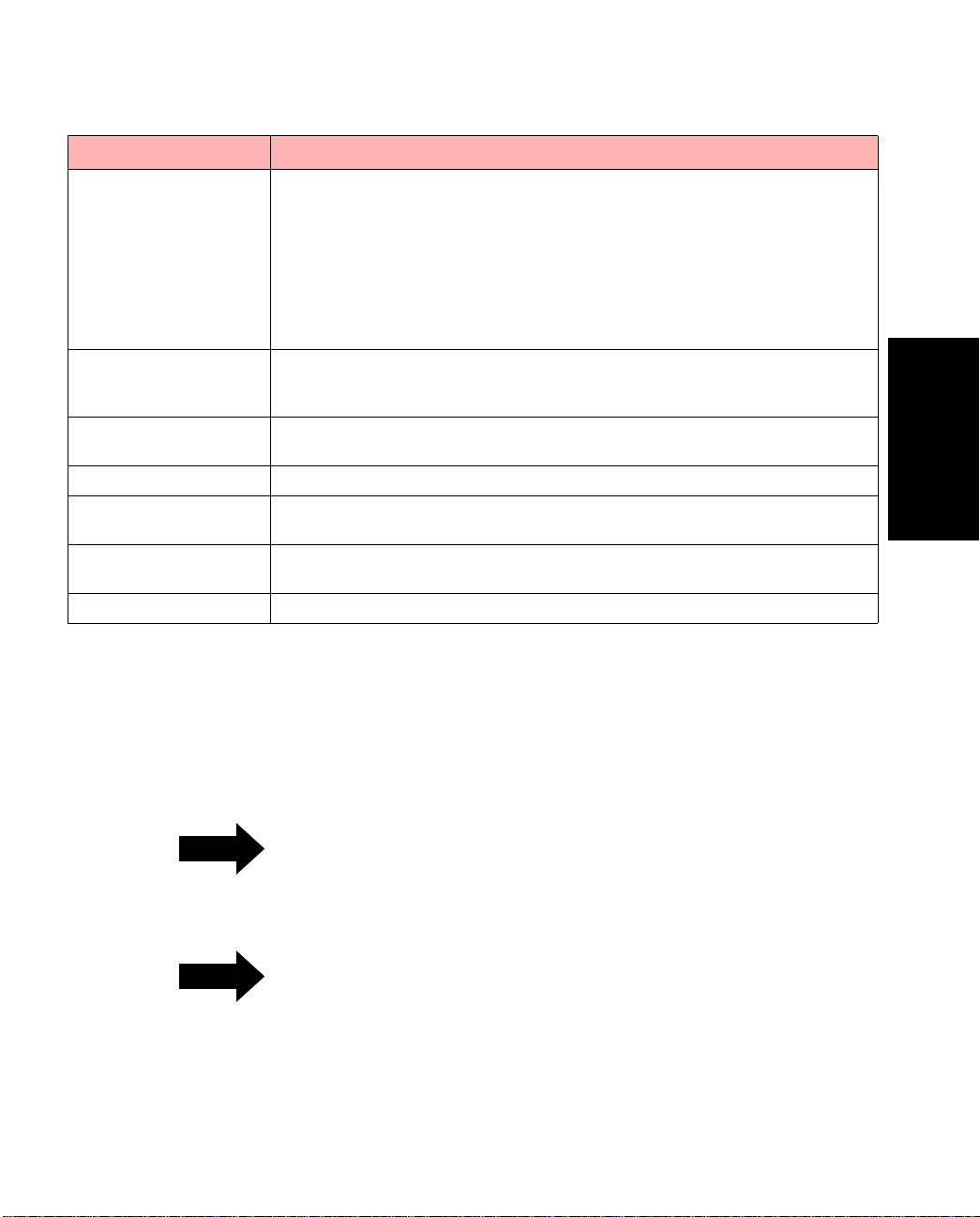
Configuring PVCs
Parameter Description
-scheduling (roundrobin |
smoothed | guarantee d)
-name <name> The user-defined name associated with this UPC traffic contract. This helps you remember
-bc <bits> The committed burst size of a connection, in bits. Can only be used on a Frame Relay con-
-be <bits> The excess bur st si ze of a connect ion, in bi ts. Can only be used on a F rame Relay connect ion.
-cir <kbps> The com mitted information rat e of a connection, in kbps. Can only be used on a Frame
-ar <kbps> The access rat e of a F rame Re lay UNI , in kbp s. C an on ly be us ed on a Fra me Rel ay co nne c-
-frsize <bytes> T h e av e rage frame size, in bytes. Can only be used on a Frame Relay connection.
1.
The units for
ond, depending on what you used for
default is
2.
The HDCOMP ASIC must be version 1 or greater to support AAL5 partial packet policing. To display the ASIC version,
use the
3.
-scheduling
The
work module platfo rm s on ly use
pcr0, pcr01, scr0, scr01, mbs0
cps
(cells per second).
conf board show advanced
option has an effect only on c on ne c t ion s with outputs on Series D n etw ork modules. All other net -
Indicates the scheduling mode to be used for servicing traffic on the output side of a Series
3
D network module.
one of the round-robin queues in the network module. This is the default mode for both
SVCs and PVCs.
network module’s rate controller, which ensures that cells for these connections are transmitted into the ne twork at a fixed rate of R cells per seco nd.
tion of the round-robin and sm oothed modes. Servic e for these connections are scheduled
with both fixe d rate R f rom the ra te co ntroller, and they h ave an e ntry in the ap propria te
round-robin queue.
for what traffic type this specific contract is used. If you do not specify a name, a default
name that relates to this type of traffic contract is assigned automatically.
nection.
Relay connection.
tion.
conf system units
command.
roundrobin
roundrobin
smoothed
mbs01
, and
scheduling.
means that all servic e fo r the se connections comes from
means that all service for these connection s comes from the
guaranteed
are specified either in cells per second or in kilobits per sec-
. To display the current s etti ng, use
conf system show
is a combina-
Configuring PVCs
. The
ForeRunner
Remember, when you create this UPC contract, it
NOTE
is not actually used until you as sign it to a VPC,
VCC, or SPANS path. UPC contracts are not
assigned to VPTs.
When the advanced options are used, they are
NOTE
converted to ATM UPC parameters and are
displayed as ATM parameters.
ATM Switch Network Configuration Manual
1 - 41
Page 72
Configuring PVCs
The following is an example of how to create a UPC contract:
myswitch::configuration upc> new 5 vbr0 500 200 250 -cdvt 1000 aal5 PPPol -name vbr0_upc
This example specifies a contract named “vbr0_upc”, which is a VBR0 contract with an index
of 5, a pcr01 of 500 cells/sec (or kbps), an scr0 of 200 cells/sec (or kbps), an mbs0 of 250 cells
(or kilobits), a CDVT of 1,000 microseconds, and partial packet policing enabled.
For more information regarding traffic contracts,
NOTE
please refer to Table 5-7 in the ATM Forum UNI
3.0 Specification.
PVCs that use UPC contracts containing any of
NOTE
the
[PPPol]]
[noGCRA]
, and
valid only when the
[aal5 [noPktDisc]
,
[ubrTagging]
options are
conf port gcrapolicing
,
conf port aal5packetdiscard, conf port
pppolicing
commands are set to
conf port show tm
, and
conf port ubrtagging
svcOn
or
svcOff
. Use
to check these settings.
1 - 42
ForeRunner
ATM Switch Network Configuration Manual
Page 73

CHAPTER 2
Configuring Classical IP
2.1 Introduction
This chapter describes how to design, configure, and maintain a Classical IP ATM network.
The term classical indicates that the ATM network has the same properties as existing legacy
LANs. That is, even though ATM technology allows for large, globally connected networks,
for example, it is only used in the LAN environment as a direct replacement of existing LAN
technology. The classical model of LANs connected through IP routers is maintained in ATM
networks. RFC-1577 provides the standard for Classical IP over ATM.
Classical IP over ATM is different than IP in legacy LANs in that ATM provides a virtual connection environment through the use of Perman ent Virtual Circuits (PVCs) and/or Switched
V ir tual Circuits (SVCs). SVC management is performed via the ATM Forum UNI 3.0 Specification, which specifies Q.2931. Q.29 31 is a broadband signalling protocol designed to es tablish
connections dynamically at the User-Network Interface (UNI). Q.2931 uses Service Specific
Connection Oriented Protocol (SSCOP) as a reliable transport protocol, and all signalling
occurs over VPI: 0, VCI: 5. Q.2931 connections are bidirectional, with the same VPI/VCI pair
used to transmit and receive.
Once a Classical IP connection has been established, IP datagrams are encapsulated using
IEEE 802.2 LLC/SNAP and are segmented in to ATM cells using ATM Adaptation Layer type 5
(AAL5). Additionally, the default Maximum Transmission Unit (MTU) is 9,180 bytes (the
SNAP header adds 8 more bytes) with a maximum packet size of 65,535 bytes. There is currently no support for IP broadcast datagrams or IP multicast datagrams in a Classical IP environment.
Configuring Classical
IP
ForeRunner
ATM Switch Network Configuration Manual
2 - 1
Page 74

Configuring Classical IP
2.1.1 Logical IP Subnets
An important concept in Classical IP networks is that of a Logical IP Subnet (LIS). An LIS is a
group of hosts configured as members of the same IP subnet (that is, they have the same IP
network and subnetwork numbers). In this sense, one LIS can be equated to one legacy LAN.
It is possible to maintain several overlaid LISs on th e same phy sical ATM network. Therefore,
in a Classical IP ATM network, placing a host on a specific subnet is a logical choice rat her
than a physical one. In this type of environment, communication between hosts in different
LISs is only permitted by communicating through an IP router which is a member of both LISs
(as per RFC-1577).
The number of LISs, and the division of hosts into each LIS, is purely an administrative issue.
Limitations of IP addressing, IP packet filtering, and administra tive boundaries may g uide a
manager into establishing several LISs onto a single ATM network. Keep in mind, though, that
communication between LISs must occur through IP routers.
2.1.2 Classical IP Interfaces
In order to support routing between multiple LISs, the switch software allows a switch to be
configured as a member of (and a router between) up to four distinct LISs. (The host adapter
software allows a host to be configured as a member of (and a router between) up to 16 distinct LISs.) Each LIS membership is through a separate Classical IP network in terface. Existing
system level IP routing configuration tools are used to control routing through each of the
Classical IP interfaces in the same mann er as routing among several phy sical int erfaces. Even
though each Classical IP interface associated with a given physical interface uses the same
physical hardware, they are each configured separately with their own MTU, IP address, and
ATM address.
By default, the name of each of the Classical IP interfaces on a switch begins with qa. (On a
host, each of the Classical IP interfaces begins with ci and is user-configurable.) On a switch,
all of the Classical IP interfaces asso ciated with physical unit zero have a as the next letter. All
of the Classical IP interfaces associated with physical unit one have b as the next letter, and so
forth. Finally, each Classical IP interface has its interface number as a suffix. As an example of
the above naming convention for switches, the name of the third Classical IP interface (unit 2)
on physical unit one is qab2.
2 - 2
ForeRunner
ATM Switch Network Configuration Manual
Page 75

Configuring Classical IP
2.1.3 SPANS Interface
While each of the Classical IP interfaces for a given physical interface is des igned to support
Classical IP using Q.2931 s ignalling, a SPANS interface also exists for each physical interface.
The SPANS interface is asx0 in switch software and is fa0 in host adapter software.
The SPANS interface supports FORE IP on top of SPANS signalling. FORE IP allows communication using AAL4 or AAL5 with no encapsulation, uses a broadcast ARP for SPANS
address resolution, and supports direct communication of all hosts on a physical ATM network without the use of IP routers. Since SPANS and Q.2931 signalling use different VCIs, a
host can simultaneously suppo rt FORE IP over SPANS as well as Classical IP over Q.2931 on
the same physical interface.
As a result of standard IP routing, all traffic sent out a SPANS interface uses FORE IP, while all
traffic sent out a Classical IP interface uses Classical IP. The Classical IP interfaces are qaaX
(where X is 0 - 3) in switch software and are ci in host adapter software.
Each of the SPANS interfaces should be assigned an IP address on a subnet different than the
subnets of any of the Classical IP interfaces. It is perm issible to place multiple SPANS interfaces on the same subnet, and the driver load balances connections across these interfaces.
It is only necessary to configure the SPANS and Classical IP interfaces if the specific service
provided by that interface is requir ed. A host sending only Classical IP would not need to configure the SPANS interfaces. Likewise, a host sending only FORE IP would not need to configure the Classical IP interfaces. Both the SPANS and Classical IP interfaces may be configured
simultaneously, but they must be in separate subnets. Remember that Classical IP specific configuration changes can only be done with th e Classical IP devices, w hile SPANS specific configuration changes can only be done with the SPANS devices.
Configuring Classical
IP
ForeRunner
ATM Switch Network Configuration Manual
2 - 3
Page 76

Configuring Classical IP
2.2 Address Registration and ILMI
Before a host can establish connections over a physical interface, the host must know the
NSAP address for that interface. The primary purpose of Interim Local Management Interface
(ILMI) is to discover and register these NSAP addresses dynamically.
2.2.1 NSAP Addresses
For private ATM networks, addresses uniquely identify ATM endpoints. The UNI 3.0 address
format is modeled after that of an OSI Network Service Access Point, hence the name NSAP
address.
Three address formats have been specified: DCC, ICD, and E.164. FORE implements the ICD
ATM format. Per the UNI 3.0 specification, al l private networks should accept ini tial call setup messages containing ATM addresses with any of the approved formats and forward the
calls as necessary.
An NSAP address consists of the following:
• a 13-byte network-side prefix - The prefix is the NSAP prefix of the switch to
which the host is attached.
• a seven-byte user-side part - This consists of the following:
- a six-byte End System Identifier (ESI) - The ESI is the unique IEEE MAC
address of the interface.
- a one-byte sel ector - Although each Classical IP interface for a given phy sical
interface uses the same prefix and ESI, the selector field is the part that indicates the number of the specific Classical IP interface. On a switch, the selector field is 00 for qaa0, 01 for qaa1, 02 for qaa2, and 03 for qaa3.
2 - 4
ForeRunner
ATM Switch Network Configuration Manual
Page 77

Configuring Classical IP
2.2.2 Operating with ILMI Support
FORE Systems switches running ForeThought software provide support for ILMI. If ILMI is
supported on all of the switches and hosts in a given network, when a switch boots up, ILMI
enables the switch to discover all of th e hosts a ttached to it and t o send its ATM prefix associated with the port to those hosts dynamically. In return, the host pr epen ds that prefix to its ESI
and selector fields, forming a complete ATM address. The host then notifies the switch of its
complete ATM address. These registration messages are sent an d received over AAL5 using
VPI: 0, VCI: 16. Once ILMI registration has been completed, then connection setup can occur.
If a host changes network ports after an ATM address has been registered for its interface, all
existing connections are closed. If the new port is on a different switch, a new ATM address
(with a different network address prefix) is registered. The host can then begin to establish
new connections.
2.2.3 Operating without ILMI Support
If ILMI is not supported on a particular switch or host in a given network, then the ATM
addresses must be manually configu red. If anot her ven dor’s switch does not support I LMI, it
can not supply an ATM pr efix to the hosts. Therefore, the user must assign a unique, valid prefix to the switch. Additionally, the same prefix should be used for all hosts attached to that
switch.
On the host, uniconfig is used to configu re the ATM address for a specific interface. The
switch directly attached to this interface is then informed of this ATM address/port combination through commands in the ATM Management Interface (AMI). Once the host and network
have both been informed of this ATM address/port pair, the host may begin signalling.
Configuring Classical
IP
2.2.4 Configuration
The choice to use ILMI for address registration is made at software installation time. Since
ILMI uses SNMP as its managem ent protocol, the use of ILMI is tied into snmpd. The choice
can be made to run FORE’s SNMP agent and use ILMI (snmpd), run FORE’s SNMP agent
without using ILMI (snmpd -n), or just use ILMI (snmpd -i or ilmid -i).
ForeRunner
ATM Switch Network Configuration Manual
2 - 5
Page 78

Configuring Classical IP
2.3 ARP and ARP Servers
2.3.1 Theory
In order for a host to establish a connection to another host, it mu st first determine the other
host’s ATM address. ATM ARP (ATM address resolution protocol) is the procedure used to
resolve an IP address into an ATM address. Since the ATM standards do not currently support
broadcast on an ATM LAN, address resolution is performed by direct communication with a
special ARP server, rather than broadcasting ARP requests as is done in legacy LANs. Each
LIS must have only one ARP server configured, but a single ARP server can be the server for
several LISs.
Each host in an LIS must be configured with the ATM address of the host providing ARP service for its LIS. On a switch, the ATM address of the ARP server can be obtained by using the
AMI command conf atmarp arpserver show. On a host, the ATM address of the ARP
server can be obtained by using clipconfig show (remember to use the interface associated
with the given LIS).
On a switch, the ATM address of the ARP server can be configured by using the instructions
found in Section 2.3.2 of this manual. On a host, the ARP server address is configured into the
host at installation time using the configure_atm script.
Since only one ARP s erver can be functioning at a tim e in a given LIS, and since the ARP
server’s address is configured into each host, it is not possible to use multiple, r edun dant ARP
servers to improve robustness. If an ARP server becomes nonfunctional, a new ARP server
must be configured, and then e ach host within the LIS must be configured to use the new ARP
server. To configure a new ARP server address on a switch, use the the instructions found in
Section 2.3.2 of this manual. To configure a new ARP server address on a host, you must delete
the interface and recreate it.
2 - 6
ForeRunner
ATM Switch Network Configuration Manual
Page 79

Configuring Classical IP
2.3.2 Configuring a FORE Switch to be an ARP Server
FORE’s A TM switches also have the capability of being an ARP server. (FORE’s ATM adapters
can not be configured as an ARP server.) To configure a ForeRunner ATM switch as an ARP
server, perform the following steps on only
1. On one of the S CPs, deter mine the ATM address of that SCP for the relevant interface (qaa0 -> qaa3) using the following AMI command:
one of the SCPs:
configuration atmarp getnsap
<interface>
For example:
configuration atmarp getnsap qaa0
qaa0 NSAP address: 47000580ffe1000000f12400de0020481900de00
2. Set the NSAP addr ess of the ARP server to be the ATM address of the interface that
you displayed in step 1 using the follow ing AMI command:
conf atmarp arpserver set
<NSAPaddress>
[
<interface>
]
For example:
conf atmarp arpserver set 0x47000580ffe1000000f12400de0020481900de00 qaa0
3. Set the ATM address of the ARP server on each of the other switches that will use
that switch as the ARP server using the same command found in step 2.
Configuring Classical
IP
ForeRunner
ATM Switch Network Configuration Manual
2 - 7
Page 80
Configuring Classical IP
2.3.3 Classical IP Operation
Once a host knows its own ATM address and the ATM address of its ARP server it attempts to
establish a connection to the ARP server, which is used to send ARP requests and receive ARP
replies. When the connection to the ARP server has been established, the ARP server sends an
inverse ARP (InARP) request on the new VC to learn the host’s IP address. When an InARP
reply is received, the ARP server places that host’s IP address to ATM address mapping in its
ARP cache. Therefore, over time, the ARP server dynamically learns th e IP-to-ATM address
mappings of all the hosts in its LIS. It can then respond to ARP requests directed toward it for
hosts in its LIS.
In order for a host to communicate with an ARP
NOTE
server, it must have learned its own ATM
address and have been configured with the ATM
address of the ARP server.
A host can not resolve the ATM addresses of
other hosts in its LIS unless it can commu nicate
with its ARP server.
Since there is no mechanism for ARP servers to
exchange mapping informa tion with each other,
it is imperative that each LIS be configured with
only one ARP server.
When a host wants to communicate with another host in its LIS, it first sends an AR P request
to the ARP server containing the IP address to be resolved. When an ARP reply is received
from the ARP server, the host creates an entry in its ARP cache for the given IP address and
stores the IP-to-ATM address mapping. This ARP cache entry is marked as complete. To
ensure that all of the IP-to-ATM address mappings known by a certain host are up-to-date,
hosts are required to age their ARP entries. A host must validate its ARP entries every 15 minutes (20 minutes on an ARP server). Any ARP entries not associated with open connections
are immediately removed.
A host validates its SVCs by sending an ARP request to th e ARP server. A host validates its
PVCs, and an ARP server validates its SVCs, by sending an InARP request on the VC. If a
reply is not received, the ARP entry is marked invalid. Once an ARP entry is marked invalid,
an attempt is made to revalidate it before transmitting. Transmission proceeds only when va lidation is successful. If a VC associated with an invalid ARP entry is closed, the entry is
removed.
2 - 8
ForeRunner
ATM Switch Network Configuration Manual
Page 81

Configuring Classical IP
2.3.4 Operational Issues
Certain hosts in an LIS may n ot support Classical IP. It is still possible to communicat e with
these hosts (and for these hosts to communicate with one another) by using static ARP entries.
If a host does not supp ort Classica l IP, its IP-to-ATM address mapping should be plac ed in it s
ARP server ’s cache as a static entry. This allows other hosts that do support Classical IP to
contact thei r ARP s erv er as usua l and obta in the cor rect ad dress m app ing. I f a ho st th at do es
not support Classical IP wants to initiate connections, the IP-to-ATM address mappings of the
destination hosts should be put in its ARP cache, again as sta tic entries. By using static ARP
entries in the above fashion, the ability fo r all hosts to communicate is maintained.
There are some restrictions on the number of hosts that can be maintained dynamically. They
are as follows:
• In the de fault co nfigurati on, a hos t can only ha ve approximately 250 virtua l connections open simultaneously. This means that an ARP s erver can only serve 250
clients, since each client must maintain a connection with its ARP server. This
may be a limitation if the ARP server is servicing multiple LIS s.
• It is possible to increase the number of connections using AMI.
• Some hosts ma y be limited to supporting a maximum of 1,024 connections per
adapter.
Configuring Classical
ForeRunner
ATM Switch Network Configuration Manual
IP
2 - 9
Page 82
Configuring Classical IP
2.4 Classical IP PVCs
2.4.1 Theory and Configuration
Normally, ATM connections in a Classical IP environment are established dynamically using
UNI 3.0 or UNI 3.1. ARP, ILMI, and UNI 3.0 or UNI 3.1 all work together as described previously to set u p an SV C. I f a host from an ot her vendor does not s upp o rt C l as si cal ARP or ILMI,
it is still possible to set up an SVC using work-arounds. If a host or a switch in an LIS does not
support UNI 3.0 or UNI 3.1, however, it is not possible to establish an SVC. In this case, a Classical IP PVC can be used for communication.
On each of the hosts, cliparp add -pvc is used to establish the PVC. A n unused VPI/VCI
pair must be chosen for each host. PVCs using the chosen VPI/VCI pairs mus t also be set up
from each of the hosts to their connecting switch, and then on all of the switches between the
two connecting switches.
Both the incoming and ou tgoing connection s are
NOTE
set up simultaneously on the host, but they must
be set up individually on the switches. The same
VPI/VCI pair is used by a host to send on the
PVC as well as receive on the PVC. The IP
datagrams are sent over the PVC using AAL5
with LLC/SNAP encapsulation.
2.4.2 Revalidation and Removal
Normally, the device driver periodically ch ecks that its PVCs are still established and functioning. A host revalidates a PVC by sending InARP requests over the PVC, if the user specifies that revalidation should occur b y using the -reval option to cliparp add -pvc at the
time the PVC is created (e.g., -reval 10 means revalidation will occur every 10 minutes). If
the equipment attached to the FORE equipment su pports revalidation, the user must choose
the -reval option. If an InARP reply is not received, the revalidation fails, the PVC is marked
invalid (as shown through cliparp show), and communication over the PVC is no longer
possible.
Once a PVC is marked invalid, an attempt is made to validate the PV C before transmitting.
Transmission proceeds only when validation is successful. It is possible to disable this revalidation feature by not specifying the -reval option. This is often desirable when the remote
end of the PVC (such as a video camera) does not support InARP.
A Classical IP PVC is removed on the host side using cliparp delete -pvc. Both the
incoming and outgoing connections are removed simultaneously. The PVC must then be
removed from each of the network switches involved.
2 - 10
ForeRunner
ATM Switch Network Configuration Manual
Page 83

Configuring Classical IP
2.5 Configuring the Network
In an ATM network, before any connections can be made, the two parties must know each
other’s ATM address in order to set up that connection.
To allow those connections to work, the ideal scenario is for all hosts and switches in the network to have support for both ILMI and for RFC-1577 (Classical IP over ATM). However,
when using other vendors’ equipment, this may not be the case. This section describes how to
configure a network with the following scenario s:
• Configuring a third-party host that has no ILMI and no RFC-1577 support
• Configuring a third-party switch that has ILMI support, but no RFC-1577 support
• Configuring a third-party switch that has no ILMI support, but has RFC-1577
support
Configuring Classical
ForeRunner
ATM Switch Network Configuration Manual
IP
2 - 11
Page 84
Configuring Classical IP
2.5.1 Third-P arty Host with No ILMI and No RFC-1577 Support
To configure a network with a third-party vendor’s host (or an edge device) that supports neither ILMI nor RFC-1577 (as shown in Figure 2.1), perform the following steps:
FORE Switch
FORE
FORE Switch
(ARP server)
FORE
Figure 2.1 -
1. Before beginning this process, be sure that ForeThought software is installed and
2. Using the configuration software of the third-party host, assign that host an NSAP
3. Configure the switch that is the ARP server so that it has a static route to the third-
conf atmr ftpnni staticroute new
Configuring a Third-Party Host with No ILMI and No RFC-1577 Support
running on the FORE equipment.
address that has the same prefix as the switch fabric to which it is connected.
party host using the following AMI command:
Be sure to use a host mask value of 152.
Third-Party Host
(no ILMI, no RFC-1577)
<NSAP> <mask>
-port
<port>
-vpi
<vpi>
2 - 12
ForeRunner
ATM Switch Network Configuration Manual
Page 85
Configuring Classical IP
2.5.2 Third-Party Switch with ILMI and No RFC-1577 Support
To configure a network with a third-party vendor’s switch that supports ILMI, but not
RFC-1577, (as shown in Figure 2.2), perform the following steps:
FORE
Switch A
= FORE Systems host
Figure 2.2 -
Configuring a Third-Party Switch with ILMI Support and No RFC-1577
1. Be sure that ForeThought software has been installed on all of the hosts and that
ILMI was set in the process. ILMI dynamically performs address registration for all
of the hosts.
2. Configure a static ATM route to the third-party switch on FORE switch “B” that is
physically connected to the third-party switch using the following AMI command:
conf atmr ftpnni staticroute new
FORE
Switch B
Third-Party Switch
ILMI, no RFC-1577
<NSAP> <mask>
-port
<port>
-vpi
Configuring Classical
IP
<vpi>
ForeRunner
Be sure to use a network mask value of 104.
3. Configure two static NSAP routes on the third-party switch, one to each of the
FORE switches to which the third-party switch is connected, using the third-party
vendor’s configuration software. Be sure to use a network mask value of 104.
ATM Switch Network Configuration Manual
2 - 13
Page 86
Configuring Classical IP
2.5.3 Third-Party Switch with RFC-1577 and No ILMI Support
To configure a network with a third-party vendor ’s switch that does not support ILMI, but
does support RFC-1577 (as shown in Figure 2.3), perform the following steps:
FORE
Switch A
= FORE Systems host
Figure 2.3 -
1. Be sure that ForeThought software has been installed on all of the FORE hosts and
that ILMI was set in the process. ILMI dynamically performs address registration
for all of the FORE hosts and FORE switches.
2. Statically configure the non-FORE (*) hosts with A TM addresses (edit the firmware
download script), using the same switch prefix for all of the hosts.
3. Configure a static ATM route to the third-party switch on FORE switch “B” that is
physically connected to the third-party switch using the AMI comm and:
Configuring a Third-Party Switch with RFC-1577 and No ILMI Support
FORE
Switch B
*
Third-Party Switch
RFC-1577, no ILMI
*
*
*
conf atmr ftpnni staticroute new
Be sure to use a network mask value of 104. Also, be sure to use the same prefix
that was used to configure the hosts.
4. Configure two static ATM routes on the third-party switch, one to each of the
FORE switches to which the third-party switch is connected, using the third-party
vendor’s configuration software. Be sure to use a network mask value of 104.
2 - 14
<NSAP> <mask>
ForeRunner
-port
ATM Switch Network Configuration Manual
<port>
-vpi
<vpi>
Page 87

CHAPTER 3
Configuring an Emulated LAN
3.1 Introduction
This chapter describes how to design, configure, and maintain an Emulated LAN (ELAN)
over an ATM network. An ELAN provides communication of user data frames among all
members of the ELAN, similar to a physical LAN. One or more ELANs may run simultaneously (and independently) on the same ATM network .
Each ELAN is composed of a set of LAN Emulation Clients (LECs), a LAN Emulation Configuration Server (LECS), and at least one LAN Emulation Server (LES) and Broadcast and
Unknown Server (BUS) pair (als o referred to as colocated BUS or an intelligent BUS). In the
current software r elease, the LECS may r eside either in a Fore Runner ASX-200WG, AS X-2 00BX ,
ASX-1000, o r LE 155 switch, or in a UNIX works tation running Sol aris 2.5, 2.5.1, or 2.6. The
LES/BUS pair may reside either in a PowerHub 7000, an ASX- 200WG , ASX -200BX , ASX -1000,
or LE 155 switch, or in a UNIX workstation running Solaris 2.5, 2.5.1, or 2.6. An additional
software feature is Distributed LAN Emulation (DLE), which provides load sharing and fault
tolerance to the ELAN.
The current software release supports the emulation of both Ethernet (IEEE 802.3) and Token
Ring ELANs.
3.1.1 Ethernet ELANs
The current software release supports emulation of Ethernet (IEEE 802.3) ELANs. In the current release, each LEC resides on an ATM host system (PC, Macintosh, UNIX workstation,
ATM switch, PowerHub 7000, or ES-3810).
3.1.2 Token Ring ELANs
The current software release supports emulation of Token Ring (IEEE 802.5) ELAN services. In
the current release, Token Ring LECs can not be created on the switch. Token Ring LECs can
only be created on some hosts.
ForeRunner
ATM Switch Network Configuration Manual
3 - 1
Configuring an
Emulated LAN
Page 88
Configuring an Emulated LAN
3.2 ELAN Components
The components of an ELAN include LECs, and LAN Emulation services consisting of a
LECS, a LES, and a BUS. Although the ATM Forum specification allows the LES and BUS to be
located on different devices, more intelligent traffic handling is possible when they are located
on the same device. ForeThought 5.0.x or greater software requires the LES and BUS be
co-located (reside on the same device).
The LECS may reside in the same physical system as the LES/BUS or in a separate physical
system. For example, the LECS could reside in a switch, while the LES/BUS reside in a workstation. In ForeThought 5.2.x software, the LECS is supported only on ForeRunner switches and
on systems running Solaris. The LES/BUS are supported only on ForeRunner switches, on
PowerHub 7000s, and on systems running Solari s. The functional interconnections of a simple
ELAN consisting of two LECs, an LECS, a LES, and a BUS are shown in Figure 3.1.
Workstation
LAN Emulation
Client
(LEC) (LEC)
Figure 3.1 -
LAN Emulation
Configuration Server
(LECS)
LAN Emulation Server
(LES)
Broadcast and Unknown
Server
(BUS)
LAN Emulation Services
Basic Emulated LAN Interconnections
Switch
or
Bridge
LAN Emulation
Client
Legacy
LAN
3 - 2
ForeRunner
ATM Switch Network Configuration Manual
Page 89

Configuring an Emulated LAN
3.2.1 LAN Emulation Client (LEC)
The LEC is the component in an end system that performs data f orwarding, address resolution,
and other control functions when communicating with other components within the ELAN. It
also provides a MAC level emulated Ethernet or Token Ring interface and appears to higher
level software as though a physical interface is present. Each LEC must register with both the
LES and BUS associated with the ELAN it wishes to join before it may participate in the ELAN.
To participate in multiple ELANs, an end system must have multiple LECs. ForeThought 5.2.x
supports up to 16 LECs on ES-3810 switches and on adapter cards running Solaris or Windows/NT software, and up to 4 LECs on on adapter cards running Windows/95.
3.2.2 LAN Emulation Configuration Server (LECS)
The LECS is responsible for the initial configuration of LECs. It provides information about
availabl e ELANs tha t a LEC may join, toge ther with t he address o f the LES a ssociated with
each ELAN. Using DLE in ForeThought 5.2, the user may also configure the LECS to associate
multiple LES/BUS pairs with a given ELAN. This feature allows LECs to use a single, anycast
address to reach one of the other DLE peer servers for their ELAN if their local server goes
down. Normal address resolution through ForeThought PNNI, ATM Forum PNNI, or IISP will
locate the closest, active LES which is using the anycast address.
3.2.3 LAN Emulation Server (LES)
The LES implements the control coordination function for the ELAN. The LES provides the
service of registering and resolving MAC addresses to ATM addresses. A LEC registers its
own address with the LES. A LEC also queries the LES when the client wishes to resolve a
MAC address to an ATM address. The LES either responds directly to the client or forwards
the query to other clients so they may respond. There may be more than one instance of an
active LES per ELAN.
3.2.4 Broadcast and Unknown Server (BUS)
Unlike traditional shared-media LAN architectures such as Ethernet or Token Ring, ATM is
connection based. Therefore, it has no built-in mechanism for handling connectionless traffic
such as broadcasts, multicasts, and unknown unicasts. In an ELAN, the BUS is responsible for
servicing these traffic types by accepting broadcast, multicast, and unknown u nicast packets
from the LECs via dedicated point-to-point connections, and forwarding the packets to all of
the members of the ELAN usin g a single point-to-multipoint connection. (Unknown unicast
packets are packets that th e sending station broadcasts because it does not yet know the ATM
address for the packet’s destination MAC address. There may be more than one instance of an
active BUS per ELAN. Using ForeThought 5.2 each BUS must be a colocated BUS (also referred
to as an intelligent BUS or a LES/BUS pair), which allows the BUS to use the LES’s registration
table to direct unicast traffic.
ForeRunner
ATM Switch Network Configuration Manual
3 - 3
Configuring an
Emulated LAN
Page 90

Configuring an Emulated LAN
3.3 Emulated LAN Operation
This section describes the operation of an ELAN and its components from the point of view of
a LEC. The operation of an ELAN may be divided into three phases:
1. Initialization
2. Registration and Addres s Resolution
3. Data Transfer
ELAN components communicate with each other using ATM connections. LECs maintain separate connections for traffic control functions and data transfer. The following connection
types are used by the LEC when operating in an ELAN:
• Configuration-Direct Connection: a tempo rary bidirectional point-to-point VCC set
up by the LEC to the LECS.
• Control- Direct Connectio n : a bidirectional point-to-point VCC set up by the LEC to
the LES. This connection must be maintained for the duration of the LEC’s participation in the ELAN.
• Control-Distribut e Connection: a unidirectional point-to-multi point VCC set up by
the LES to the LEC. This connection must be maintained for the duration of the
LEC’s participation in the ELAN.
• Multicast-Send Connection: a bidirectional point-to-point VCC set up by the LEC to
the BUS for sending multicast data to the BUS. The LEC must attempt to maintain
this connection while participating in the ELAN.
• Multicast-Forward Connection: a unidirectional point-to-multipoint VCC set up
from the BUS to LECs participating in the ELAN. The LEC must attempt to maintain this connection while parti c ipating in the ELAN.
• Data-Direct Connection: a bidirectional point-to-point VCC set up between LECs
that want to exchange unicast data traffic, and torn down after 20 minutes
(default) of inactivity. Each LEC normally establishes many D ata-Direct Connections.
For the following discussion, please refer to Figure 3.2.
3 - 4
ForeRunner
ATM Switch Network Configuration Manual
Page 91
Configuring an Emulated LAN
DATA - DIRECT
➏
LEC1
LEC2
➊ CONFIGURATION - DIRECT
➋ CONTROL - DIRECT
➌ CONTROL - DISTRIBUTE
➍
MULTICAST - SEND
➎
MULTICAST - FORWARD
LECS
LES
BUS
engineering
Configuring an
Emulated LAN
ForeRunner
Figure 3.2 -
ATM Switch Network Configuration Manual
ELAN Operation
3 - 5
Page 92
Configuring an Emulated LAN
3.3.1 Initialization
Upon initialization, LEC1 obtains its own ATM address via ILMI address registration. LEC1
obtains the address of the LECS in one of four ways: by querying the switch to which LEC1 is
connected via ILMI, by connecting to the “well-known” address defined by the ATM Forum’s
LANE standards (47.0079.00.000000.0000.0000.0000.00A03E000001.00), by using
PVC (0,17), or by using an address that is locally configured on LEC1.
Once it knows the location of the LECS, LEC1 establishes a configuration-direct connection
to the LECS. When connected, the LECS provides LEC1 with the information necessary to connect to the ELAN it wishes to join. This informatio n includes such parameters as: the ATM
address of the ELAN’s LES, the type of LAN being emulated, the maximum packet size, and
the name of the ELAN (engineering, for example). This configuration information is co ntained in a configuration file that must be built and maintained by the network administrator.
Detailed information about the LECS
NOTE
configuration file may be found in Section 3.6.1.
➊
3 - 6
ForeRunner
ATM Switch Network Configuration Manual
Page 93
3.3.2 Registration and Address Resolution
Configuring an Emulated LAN
After obtaining the address of the LES, LEC1 establishes a control-direct connection ➋
LES.
When using DLE, this address is a single, anycast
NOTE
NOTE
The LES assigns LEC1 a unique identifier, and LEC1 registers its own MAC and ATM
addresses with the LES. (The LES maintains a table containing the MAC addresses and corresponding ATM addresses of all members of the ELAN.) At this point, LEC1 has “joined” the
ELAN.
The LES then establishes a control-distribute connection
address which allows the LEC to reach one of the
other DLE peer servers for its ELAN if its local
server goes down. This address is routed via
PNNI to the nearest active DLE peer server for
this ELAN.
If the LES is configured to perform ELAN access
control (see Section 3.5), upon receiving a request
from a LEC to join the ELAN, the LES sends a
message to the LECS to verify that the LEC is
allowed to join. If verification is received from
the LECS, then the LES gives the LEC permission
to join. If verification is not received from the
LECS, the LES rejects the join request and the
LEC is dropped.
➌
back to LEC1. Connections
to the
➋ and
➌ can now be used by LEC1 to send LAN Emulation ARP (LE_ARP) requests to the LES, and
receive replies.
Configuring an
Emulated LAN
LEC1 now sends an LE_ARP request to the LES to get the ATM address of the BUS corresponding to the broadcast MAC address (FF-FF-FF-FF-FF-FF). The LEC then establishes a
multicast-send connection
connection
At this point, the LEC is ready to transfer data.
ForeRunner
➎
to the LEC.
ATM Switch Network Configuration Manual
➍
to the BUS. The BUS responds by setting up a multicast-forward
3 - 7
Page 94
Configuring an Emulated LAN
3.3.3 Data Transfer
When LEC1 receives a network-layer packet from a higher lay er protocol to tra nsmit to some
destination MAC address (for example, LEC2), LEC1 initially does not know the corresponding ATM address of the destination. Consequently, LEC1 transmits an LE_ARP request to the
LES.
The example shown in Figure 3.2 assumes that
NOTE
While waiting for the LES to respond, LEC1 forwards the packet to the BUS. The BUS broadcasts the packet to all LECs on the ELAN. This is done to avoid data loss, and to minimize connection set-up latency (due to the LE_ARP process) that may not be acceptable to some
network protocols.
LEC2 has already registered with the LES, and
that connections similar to those described for
LEC1 already exist.
If the LE_ARP response is received, LEC1 establishes a data-direct connection
nation address of LEC2. This path will be used for s ubsequent data transfers. Before LEC1
begins to use this connection, it first sends a “flush” packet via the BUS to the destination,
LEC2. When LEC2 acknowledges receipt of this packet, signifying that the BUS path is empty,
only then does LEC1 begin to use the data-direct connection
ensures that the network protocol’s frames arrive in the proper order.
If no response is received to the LE_ARP, LEC1 continues to send data via the BUS, while continuing to LE_ARP until a response is received and a data-direct connection to LEC2 is established.
If LEC1 already has a data-direct connection to a MAC address it wishes to reach, it need not
go through the LE_ARP process again. Instead, it continues to use the current connection. This
is possibl e because each LEC maintai ns a cache of MAC address to ATM address mapping s
that it receives in response to the LE_ARPs it has sent. Entries in this cache are “aged” out over
a period of time. Data-direct connections ar e also clear ed if they r emain inactive for a period of
time.
➏
for data transfer. This process
➏ to the desti-
3 - 8
ForeRunner
ATM Switch Network Configuration Manual
Page 95
Configuring an Emulated LAN
3.4 Distributed LAN Emulation
Distributed LAN Emulation (DLE) allows the LES and BUS functions that are provided to
each ELAN to be distributed among multiple, interconnected server platforms. In this way,
DLE provides these ELANs with resiliency and scalability.
To understand DLE opera tion, it is useful to co mpar e DLE to the current LANE service model,
which uses a single LES and BUS for each ELAN. This section first describes a simple example
of the single server model and then gives a detailed overview of the DLE model.
3.4.1 Single Server LANE Services Model
Figure 3.3 shows the topology of a single server supporting an ELAN. In this exam ple, the
LECs are hosts that are using IP, and the LES and BUS are running on the same switch. Three
LANE LECs are all registered in the same ELAN called Eng, and each is, therefore, connected
to a LES and to a BUS for that ELAN.
Eng
LES/BUS 1
ForeRunner
Eng LEC 1 Eng LEC 2 Eng LEC 3
Figure 3.3 -
ATM Switch Network Configuration Manual
Single Server LANE Services Model
3 - 9
Configuring an
Emulated LAN
Page 96
Configuring an Emulated LAN
3.4.1.1 Using a Single Server
When LEC 1 wants to contact LEC 3, several messages are exchanged. First, LEC 1 attempts to
learn the MAC address of LEC 3 by broadcasting an IP-ARP request with LEC 3’s IP address.
As Figure 3.4 shows, this ARP request is sent in two steps:
LEC 1 to the LANE BUS, then
LECs registered in the ELAN.
➋ as a point-to-multipoint message from the BUS to all of the
Eng
LES/BUS 1
➊ as a point-to-point message from
➊
➋
Eng LEC 1 Eng LEC 2 Eng LEC 3
Figure 3.4 -
When LEC 3 receives the IP ARP request, it recognizes that it is the intended destination, and,
therefore, attempts to send an IP ARP response to LEC 1 (who se MAC address was supplied
in the ARP request packet).
As shown in Figure 3.5, the delivery of the ARP response is a three-step process:
sends an LE-ARP query to the LES, asking for the ATM address that corresponds to LEC 1’s
MAC address;
cuit to LEC 1’s ATM address.
➍ the LES sends an LE-ARP response to LEC 3; and ➎ LEC 3 establishes a cir-
Eng LEC 1 Eng LEC 2 Eng LEC 3
Figure 3.5 -
Broadcast IP-ARP Request
Eng
LES/BUS 1
➎
IP ARP Response Handling
➍
➌
➌ LEC 3
3 - 10
ForeRunner
ATM Switch Network Configuration Manual
Page 97

Configuring an Emulated LAN
3.4.1.2 Limitations of a Single Server
Because the there is only one LES/BUS supporting the ELAN, the following limitations exist:
• The number of LECs in a single ELAN is limited by the number of virtual circuits
that the single LES/BUS can establish through their platform’s ATM port. This
usually limits the ELAN to about 500 LECs.
• Clusters of LECs that are geographically separated from the LES/BUS may have
poor throughput, even when connecting to each other, because address queries
and broadcasts may traverse slow wide-area links.
• A failure of the LES or BUS brings down the ELAN.
ForeRunner
ATM Switch Network Configuration Manual
3 - 11
Configuring an
Emulated LAN
Page 98
Configuring an Emulated LAN
3.4.2 Distributed LAN Emulation Model
To address the limitations of the single server model, DLE distributes the LANE services load
among a mesh of LES/BUS DLE peer servers, as shown in Figure 3.6.
Eng
LES/BUS 1
Eng LEC 1 Eng LEC 2 Eng LEC 3
Figure 3.6 -
Eng
LES/BUS 2
Eng LEC 4
Eng LEC 5 Eng LEC 7 Eng LEC 8 Eng LEC 9
Eng LEC 6
Distributed LAN Emulation Model
Eng
LES/BUS 3
Each DLE peer server actually maintains two sets of connections: one is a point-to-multipoint
connection to each of its peers for broadcasting mu lticast data and flo oding contr ol information,
and the other includes individual point-to-point connections to each peer for directed control
traffic.
Each DLE peer server that supports the ELAN is responsible for registering and giving reports
about the LECs that are attached to it directly. Each DLE peer server propagates this information to both its locally attached LECs and its peers.
Each device running a DLE peer server must use
NOTE
ForeThought 5.0 or greater; however, the DLE
peer servers support clients and attached
switches using ForeThought 4.0 and 4.1, and
third-party devices that are ATM Forum LANE
1.0 compliant.
3 - 12
ForeRunner
ATM Switch Network Configuration Manual
Page 99
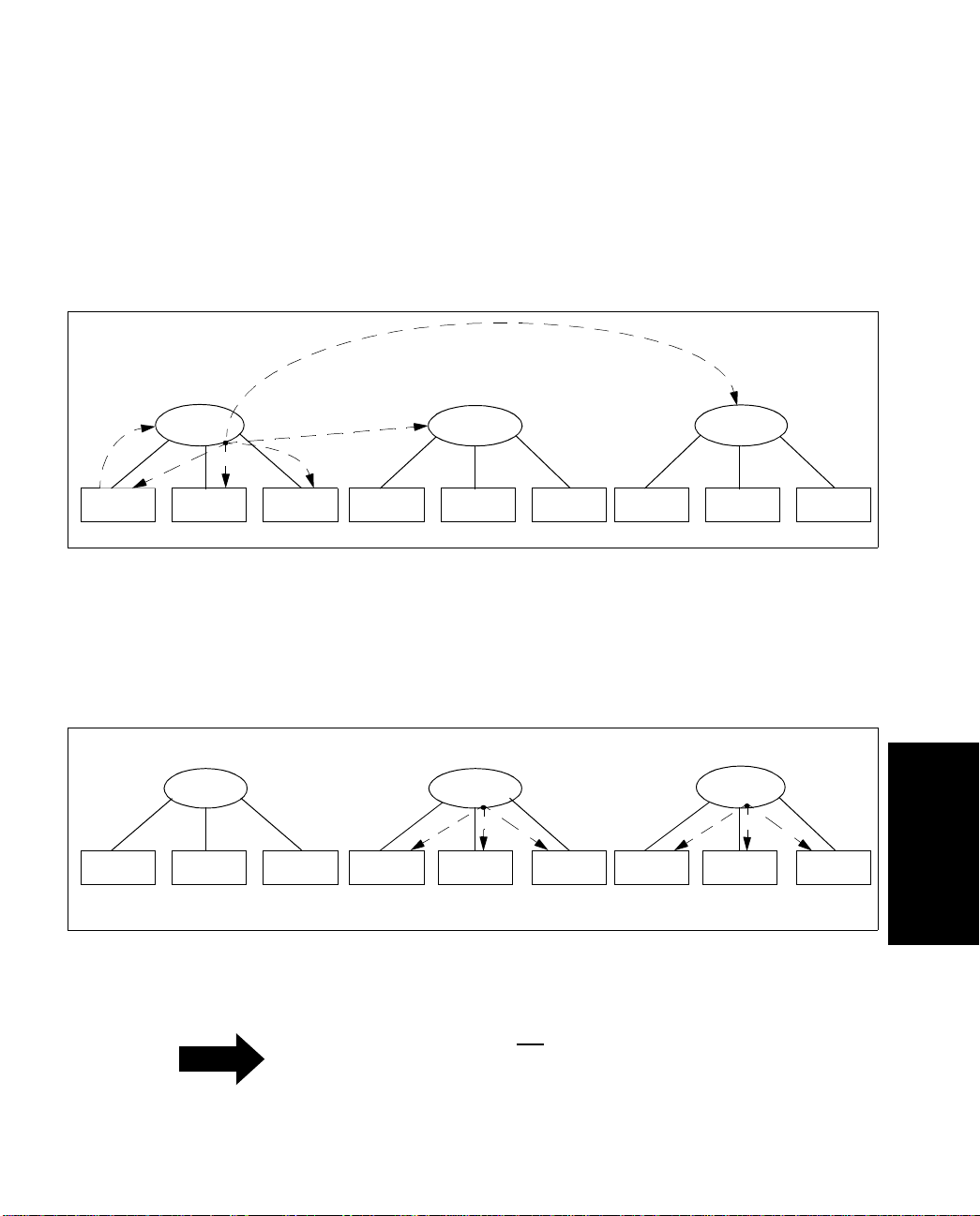
Configuring an Emulated LAN
3.4.2.1 Using DLE
Figure 3.7 shows how a connection begins to be established through DLE peer servers. LEC 1
wants to communicate with LEC 9, which is in the same ELAN, but is locally attached to a different DLE peer server. First,
Then,
➋ the BUS broadcasts the packet to both its locally attached LECs and its DLE peer
servers.
➊ LEC 1 sends an IP ARP broadcast request to its local DLE BUS.
➊
Eng
LES/BUS 1
➋
Figure 3.7 -
Eng LEC 4 Eng LEC 5 Eng LEC 6 Eng LEC 7 Eng LEC 8 Eng LEC 9Eng LEC 1 Eng LEC 2 Eng LEC 3
IP ARP Broadcast from LEC 1 to LEC 9
Eng
LES/BUS 2
Eng
LES/BUS 3
Upon receiving the broadcast from the first DLE peer server, the peers re-distribute the packet
to their own locally attached LECs
➌, as shown in Figure 3.8, so the packet a rrives its actual
destination at LEC 9.
Eng
LES/BUS 1
Eng
LES/BUS 2
Eng LEC 4 Eng LEC 5 Eng LEC 6 Eng LEC 7 Eng LEC 8 Eng LEC 9Eng LEC 1 Eng LEC 2 Eng LEC 3
➌
LES/BUS 3
➌
Eng
Configuring an
Emulated LAN
ForeRunner
Figure 3.8 -
Re-distributing the Broadcast across DLE Peer Servers
The peers do not
NOTE
ATM Switch Network Configuration Manual
peers; this would create a loop.
re-distribute the packet to other
3 - 13
Page 100
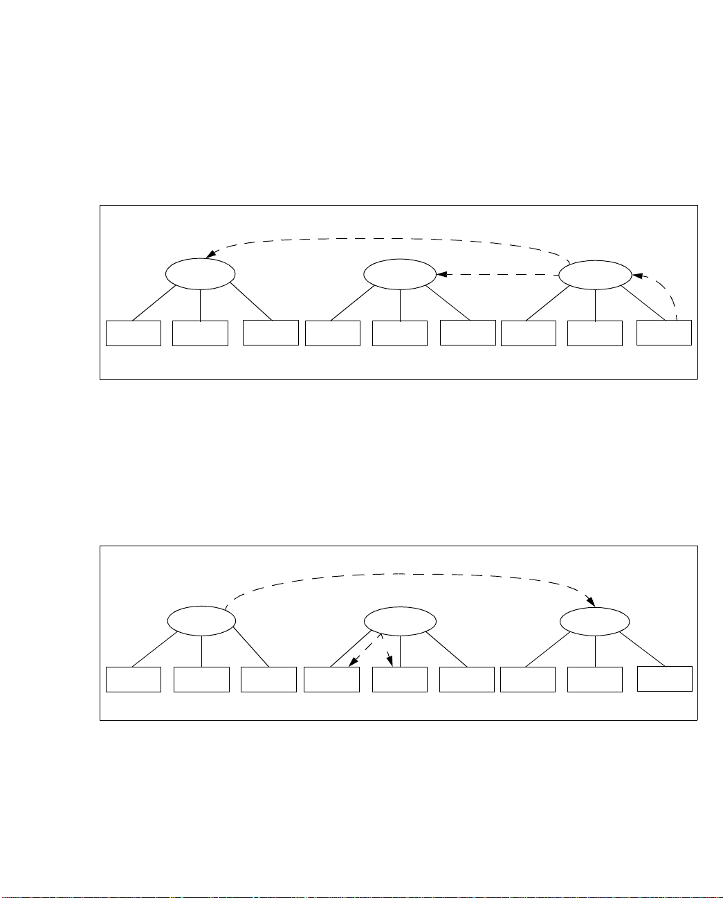
Configuring an Emulated LAN
LEC 9 recognizes its IP address, and prepares an IP ARP response. As shown in Figure 3.9, it
then sends an LE-ARP request to its local LES
➍, asking for the ATM address that matches
LEC 1’s MAC address. Since LEC 9’s local LES does not have an entry for LEC 1, the local LES
passes the query along to all of its locally-attached proxy LECs (none are shown in this figure)
and all of its DLE peer servers
➎.
Eng
LES/BUS 1
Eng LEC 4 Eng LEC 5 Eng LEC 6 Eng LEC 7 Eng LEC 8 Eng LEC 9Eng LEC 1 Eng LEC 2 Eng LEC 3
Eng
LES/BUS 2
➎
Eng
LES/BUS 3
➍
Figure 3.9 - LE-ARP for Unknown Host Sent to Proxies (not shown) and DLE Peer Servers
In Figure 3.10, the second DLE peer server is attached to two proxy LECs (LEC 4 and LEC 5).
When the DLE peer server receives the LE-ARP query, it cannot resolve the query, so the DLE
peer server re-distributes the query to its proxy LECs
➏ (but not to its peer servers again, to
avoid a loop). Meanwhile, the first peer server has been able to resolve the LE-ARP for the
address of LEC 1 and has sent an LE-ARP response to the third server
➐.
➐
Eng
LES/BUS 1
➏
Eng
LES/BUS 2
Eng
LES/BUS 3
Eng LEC 4 Eng LEC 5 Eng LEC 6 Eng LEC 7 Eng LEC 8 Eng LEC 9Eng LEC 1 Eng LEC 2 Eng LEC 3
Figure 3.10 - LE-ARP Query Answered by One DLE Peer Server and Re-distributed by Another
3 - 14
ForeRunner
ATM Switch Network Configuration Manual
 Loading...