

Page 1

óæ
FORE Systems
ES-2810 Ethernet Switch
User’s Manual
MANU0330-02 - Rev. A - November, 1998
Firmware Version 2.31
Stack View Version 2.00
FORE Systems, Inc.
1000 FORE Drive
Warrendale, PA 15086-7502
Phone: 724-742-4444
FAX: 724-772-6500
URL: http://www.fore.com
Page 2

Legal Notices
Copyright © 1998 FORE Systems, Inc.
All rights reserved.
U.S. Government Restricted Rights.
the following provisions apply to you. If the Software is supplied to the Department of Defense (“DoD”), it is classified as
“Commercial Computer Software” under paragraph 252.227-7014 of the DoD Supplement to the Federal Acquisition Regulations (“DFARS”) (or any successor regulations) and th e Government is ac quiring only the li cense rights grante d herein
(the license rights customarily provided to non-Government users). If the Software is supplied to any unit or agency of the
Government other than DoD, it is classifi ed as “Restricte d Computer Software” and the Governmen t’s rights in the Software are defined in paragraph 52.227-19 of th e Federal A cquisition Regulations (“ FAR”) (or any successor regulations) or,
in the cases of NASA, in paragraph 18. 52. 227 -86 of the NASA Supplement to the FAR (or any successor regulations).
If you are licensing the Software on beha lf of the U.S. Governme nt (“Govern ment”),
FCC CLASS A NOTICE
WARNING: Changes or mo difications to this unit not expressly approved by t he party responsible for co mpliance co uld
void this user’s authority to operate this equipment.
NOTE: The ES-281 0 Ethernet Switch h as been tested and found to comply with the limits for a Class A digital d e vice, pursuant to Part 15 of the FCC Rules. These limits are designed to provide reasonable protection against harmful interference
when the equipment is operated in a commercial environment. This equipment generates, uses, and can radiate radio frequency energy and, if not installed and used in accord an ce with the in st r u ction manual, may cause harmful interference to
radio communications. Operation of the equipment in a residential area is likely to cause harmful interference in which
case the user will be required to correct the interference at his own expense.
Page 3

CE
NOTICE
Marking by the symbol CE indi cates comp liance of this syst em to the EMC (E lectromagn etic Compatib ility) directiv e of
the European Community and co mplia nce to the Low Voltage (Safety) Directive. Such markin g is indic ative tha t this sys tem meets or exceeds the following technical standa rds:
•EN 55022 - “Limits and Methods of Measurement of Radio Interference Characteristics of Information Technology Equipment.”
•EN 50082-1 - “Electromagnet ic compatibilit y - Generic immun ity standard Part 1: Resid ential, commercial, and light in dustry.”
•IEC 1000-4-2 - “Electromagnetic compatibility for industrial-process measurement and control equipment Part 2: Electrostatic discharge requirements.”
•IEC 1000-4-3 - “Electromagnetic compatibility for industrial-process measurement and control equipment Part 3: Radiate electromagnetic field requirements.”
•IEC 1000-4-4 - “Electromagnetic compatibility for industrial-process measurement and control equipment Part 4: Electrica l fast tr an sient/burst requirements.”
•IEC 1000-4-5 - “Elect romagn et ic compatibility - Generi c immunity standard Part 5: Surge test.”
CERTIFICATIONS
ETL certified to meet Information Technology Equipment safety standards UL 1950, CSA 22. 2 No . 95 0, and EN 60950.
TRADEMARKS
FORE System s,
unregistered trademarks of FORE Systems, Inc. All other brands or product names are trademarks or registered trademarks of
their respective holders.
ForeRunner
, and
ForeView
are registered trademarks of FORE Systems, Inc.
ForeRunnerLE
and
CellPath
are
Page 4

Page 5

Table of Contents
CHAPTER 1 Introduction to the ES-2810
1.1 Introduction to the product . . . . . . . . . . . . . . . . . . . . . . . . . . . . . . . . . . . . . . . . . . . . 1-2
1.1.1 Purpose of the Switch . . . . . . . . . . . . . . . . . . . . . . . . . . . . . . . . . . . . . . .1-2
1.1.2 Physical Features. . . . . . . . . . . . . . . . . . . . . . . . . . . . . . . . . . . . . . . . . . . 1-2
1.1.3 Hardware Features. . . . . . . . . . . . . . . . . . . . . . . . . . . . . . . . . . . . . . . . . . 1-2
1.1.4 Software Features . . . . . . . . . . . . . . . . . . . . . . . . . . . . . . . . . . . . . . . . . . 1-3
1.2 Front Panel . . . . . . . . . . . . . . . . . . . . . . . . . . . . . . . . . . . . . . . . . . . . . . . . . . . . . . . . 1-4
1.2.1 Introduction. . . . . . . . . . . . . . . . . . . . . . . . . . . . . . . . . . . . . . . . . . . . . . . . 1-4
1.2.2 View of the Front Panel . . . . . . . . . . . . . . . . . . . . . . . . . . . . . . . . . . . . . . 1-4
1.2.3 Front Panel Ports . . . . . . . . . . . . . . . . . . . . . . . . . . . . . . . . . . . . . . . . . . . 1-4
1.2.4 Slots for Media Modules. . . . . . . . . . . . . . . . . . . . . . . . . . . . . . . . . . . . . .1-5
1.2.5 Front Panel LED Functions. . . . . . . . . . . . . . . . . . . . . . . . . . . . . . . . . . . .1-5
1.2.6 Buttons . . . . . . . . . . . . . . . . . . . . . . . . . . . . . . . . . . . . . . . . . . . . . . . . . . . 1-5
1.3 Rear Panel . . . . . . . . . . . . . . . . . . . . . . . . . . . . . . . . . . . . . . . . . . . . . . . . . . . . . . . . 1-6
1.3.1 Introduction. . . . . . . . . . . . . . . . . . . . . . . . . . . . . . . . . . . . . . . . . . . . . . . . 1-6
1.3.2 View of Rear Panel. . . . . . . . . . . . . . . . . . . . . . . . . . . . . . . . . . . . . . . . . . 1-6
1.3.3 Rear Panel Parts . . . . . . . . . . . . . . . . . . . . . . . . . . . . . . . . . . . . . . . . . . . 1-6
1.4 Installation . . . . . . . . . . . . . . . . . . . . . . . . . . . . . . . . . . . . . . . . . . . . . . . . . . . . . . . . 1-7
1.4.1 Important . . . . . . . . . . . . . . . . . . . . . . . . . . . . . . . . . . . . . . . . . . . . . . . . . 1-7
1.4.2 Before Installation. . . . . . . . . . . . . . . . . . . . . . . . . . . . . . . . . . . . . . . . . . . 1-7
1.4.2.1 Contents of the Pack . . . . . . . . . . . . . . . . . . . . . . . . . . . . . . . . . . 1-7
1.4.2.2 Check the Package Contents . . . . . . . . . . . . . . . . . . . . . . . . . . . 1-8
1.4.2.3 Check All Labels . . . . . . . . . . . . . . . . . . . . . . . . . . . . . . . . . . . . . 1-8
1.4.2.4 Essential Reading . . . . . . . . . . . . . . . . . . . . . . . . . . . . . . . . . . . . 1-8
1.5 Positioning and Installing the Switch . . . . . . . . . . . . . . . . . . . . . . . . . . . . . . . . . . . . 1-9
1.5.1 Allow Adequate Ventilation. . . . . . . . . . . . . . . . . . . . . . . . . . . . . . . . . . . . 1-9
1.5.2 On a Desktop . . . . . . . . . . . . . . . . . . . . . . . . . . . . . . . . . . . . . . . . . . . . . .1-9
1.5.3 Rack Requirements . . . . . . . . . . . . . . . . . . . . . . . . . . . . . . . . . . . . . . . . 1-10
1.5.4 Mounting Kit . . . . . . . . . . . . . . . . . . . . . . . . . . . . . . . . . . . . . . . . . . . . . . 1-10
1.5.5 Tools Required for Positioning in a Rack . . . . . . . . . . . . . . . . . . . . . . . . 1-10
1.5.6 In an Equipment Rack . . . . . . . . . . . . . . . . . . . . . . . . . . . . . . . . . . . . . . 1-11
1.5.7 Ambient Temperature. . . . . . . . . . . . . . . . . . . . . . . . . . . . . . . . . . . . . . . 1-11
1.6 Installing a Module . . . . . . . . . . . . . . . . . . . . . . . . . . . . . . . . . . . . . . . . . . . . . . . . . 1-12
1.6.1 Introduction. . . . . . . . . . . . . . . . . . . . . . . . . . . . . . . . . . . . . . . . . . . . . . . 1-12
1.6.2 Static-free Working Area . . . . . . . . . . . . . . . . . . . . . . . . . . . . . . . . . . . .1-12
FORE Systems ES-2810 Ethernet Swtich User’s Manual
TOC - 1
Page 6

Table of Contents
1.6.3 Avoiding Damage to the Circuit Board. . . . . . . . . . . . . . . . . . . . . . . . . . 1-12
1.6.4 Installing a Module . . . . . . . . . . . . . . . . . . . . . . . . . . . . . . . . . . . . . . . . 1-13
1.6.5 Removing a Module. . . . . . . . . . . . . . . . . . . . . . . . . . . . . . . . . . . . . . . . 1-13
1.7 Connecting Other Devices. . . . . . . . . . . . . . . . . . . . . . . . . . . . . . . . . . . . . . . . . . . 1-14
1.7.1 Introduction . . . . . . . . . . . . . . . . . . . . . . . . . . . . . . . . . . . . . . . . . . . . . . 1-14
1.7.2 Use Shielded Cables. . . . . . . . . . . . . . . . . . . . . . . . . . . . . . . . . . . . . . . 1-14
1.7.3 Cables for the LAN Ports. . . . . . . . . . . . . . . . . . . . . . . . . . . . . . . . . . . . 1-14
1.7.4 RJ-45 Connector Pin Assignments . . . . . . . . . . . . . . . . . . . . . . . . . . . . 1-14
1.7.5 Connecting a Device to the RJ-45 Ports . . . . . . . . . . . . . . . . . . . . . . . . 1-15
1.7.6 Cable for the Console Port . . . . . . . . . . . . . . . . . . . . . . . . . . . . . . . . . . 1-15
1.8 Connecting the Power . . . . . . . . . . . . . . . . . . . . . . . . . . . . . . . . . . . . . . . . . . . . . . 1-16
1.8.1 Introduction . . . . . . . . . . . . . . . . . . . . . . . . . . . . . . . . . . . . . . . . . . . . . . 1-16
1.8.2 The Power Cable. . . . . . . . . . . . . . . . . . . . . . . . . . . . . . . . . . . . . . . . . . 1-16
1.8.2.1 Ground Warning . . . . . . . . . . . . . . . . . . . . . . . . . . . . . . . . . . . . 1-16
1.8.2.2 Power Cable Wiring Color Code. . . . . . . . . . . . . . . . . . . . . . . . 1-16
1.8.2.3 Important for UK Use . . . . . . . . . . . . . . . . . . . . . . . . . . . . . . . . 1-16
1.8.3 Power Supply to a Rack . . . . . . . . . . . . . . . . . . . . . . . . . . . . . . . . . . . . 1-17
1.9 Power Up . . . . . . . . . . . . . . . . . . . . . . . . . . . . . . . . . . . . . . . . . . . . . . . . . . . . . . . . 1-18
1.9.1 Powering Up the Switch. . . . . . . . . . . . . . . . . . . . . . . . . . . . . . . . . . . . . 1-18
1.9.2 Start-up Procedure . . . . . . . . . . . . . . . . . . . . . . . . . . . . . . . . . . . . . . . . 1-18
1.9.3 Port LED States. . . . . . . . . . . . . . . . . . . . . . . . . . . . . . . . . . . . . . . . . . . 1-19
1.9.4 Default Settings After Start-up. . . . . . . . . . . . . . . . . . . . . . . . . . . . . . . . 1-20
1.9.5 After Start-up. . . . . . . . . . . . . . . . . . . . . . . . . . . . . . . . . . . . . . . . . . . . . 1-20
1.10 Other LEDs on the Front Panel . . . . . . . . . . . . . . . . . . . . . . . . . . . . . . . . . . . . . . . 1-21
1.10.1 Introduction . . . . . . . . . . . . . . . . . . . . . . . . . . . . . . . . . . . . . . . . . . . . . . 1-21
1.10.2 LED Colors and their Meanings . . . . . . . . . . . . . . . . . . . . . . . . . . . . . . 1-21
1.10.3 Port Status Button . . . . . . . . . . . . . . . . . . . . . . . . . . . . . . . . . . . . . . . . . 1-22
CHAPTER 2 FORE Stack View
2.1 In This Chapter . . . . . . . . . . . . . . . . . . . . . . . . . . . . . . . . . . . . . . . . . . . . . . . . . . . . 2-1
2.2 System Requirements . . . . . . . . . . . . . . . . . . . . . . . . . . . . . . . . . . . . . . . . . . . . . . . 2-2
2.2.1 Requirements for FORE Stack View under Windows . . . . . . . . . . . . . . . 2-2
2.2.2 DHCP Limitation . . . . . . . . . . . . . . . . . . . . . . . . . . . . . . . . . . . . . . . . . . . 2-2
2.3 Installation and Removal . . . . . . . . . . . . . . . . . . . . . . . . . . . . . . . . . . . . . . . . . . . . . 2-3
2.3.1 To start the installation of FORE Stack View. . . . . . . . . . . . . . . . . . . . . . 2-3
2.3.2 To Install FORE Stack View for Windows . . . . . . . . . . . . . . . . . . . . . . . . 2-3
2.4 Removal of FORE Stack View. . . . . . . . . . . . . . . . . . . . . . . . . . . . . . . . . . . . . . . . . 2-4
2.4.1 Removal under Windows. . . . . . . . . . . . . . . . . . . . . . . . . . . . . . . . . . . . . 2-4
2.5 Using FORE Stack View . . . . . . . . . . . . . . . . . . . . . . . . . . . . . . . . . . . . . . . . . . . . . 2-5
2.5.1 Concept. . . . . . . . . . . . . . . . . . . . . . . . . . . . . . . . . . . . . . . . . . . . . . . . . . 2-5
2.5.2 Navigating through FORE Stack View. . . . . . . . . . . . . . . . . . . . . . . . . . . 2-6
TOC - 2
FORE Systems ES-2810 Ethernet Swtich User’s Manual
Page 7

2.5.3 The FORE Stack View Window . . . . . . . . . . . . . . . . . . . . . . . . . . . . . . . . 2-6
2.6 Before a Switch is Contacted . . . . . . . . . . . . . . . . . . . . . . . . . . . . . . . . . . . . . . . . . .2-7
2.6.1 Basic Menu Bar Commands. . . . . . . . . . . . . . . . . . . . . . . . . . . . . . . . . . . 2-7
2.6.2 File Menu . . . . . . . . . . . . . . . . . . . . . . . . . . . . . . . . . . . . . . . . . . . . . . . . . 2-7
2.6.3 Device Menu. . . . . . . . . . . . . . . . . . . . . . . . . . . . . . . . . . . . . . . . . . . . . . . 2-7
2.6.4 View menu — for Windows Users Only . . . . . . . . . . . . . . . . . . . . . . . . . . 2-7
2.6.5 Monitoring Menu. . . . . . . . . . . . . . . . . . . . . . . . . . . . . . . . . . . . . . . . . . . . 2-7
2.6.6 Tools Menu . . . . . . . . . . . . . . . . . . . . . . . . . . . . . . . . . . . . . . . . . . . . . . . . 2-8
2.6.7 Help Menu . . . . . . . . . . . . . . . . . . . . . . . . . . . . . . . . . . . . . . . . . . . . . . . . 2-8
2.7 After a Switch or Stack is Contacted . . . . . . . . . . . . . . . . . . . . . . . . . . . . . . . . . . . . 2-9
2.7.1 Commands. . . . . . . . . . . . . . . . . . . . . . . . . . . . . . . . . . . . . . . . . . . . . . . . 2-9
2.8 Setting the Preferences . . . . . . . . . . . . . . . . . . . . . . . . . . . . . . . . . . . . . . . . . . . . . 2-10
2.8.1 Setting the Polling Intervals . . . . . . . . . . . . . . . . . . . . . . . . . . . . . . . . . . 2-10
2.8.2 Setting the Timeout Parameters for SNMP . . . . . . . . . . . . . . . . . . . . . .2-11
2.8.3 Setting the Community for SNMP Polling. . . . . . . . . . . . . . . . . . . . . . . . 2-12
2.9 Installing and Managing Switches . . . . . . . . . . . . . . . . . . . . . . . . . . . . . . . . . . . . . 2-13
2.9.1 Following Installation of FORE Stack View. . . . . . . . . . . . . . . . . . . . . . . 2-13
2.9.2 Adding New Switches. . . . . . . . . . . . . . . . . . . . . . . . . . . . . . . . . . . . . . . 2-13
2.9.3 The Install Wizard. . . . . . . . . . . . . . . . . . . . . . . . . . . . . . . . . . . . . . . . . . 2-13
2.9.4 Matrix Module Connected to a New Switch . . . . . . . . . . . . . . . . . . . . . . 2-14
2.9.5 Managing an Existing Switch or Stack . . . . . . . . . . . . . . . . . . . . . . . . . . 2-15
2.9.6 Establishing and Expanding a Stack . . . . . . . . . . . . . . . . . . . . . . . . . . .2-16
2.10 Device Tree. . . . . . . . . . . . . . . . . . . . . . . . . . . . . . . . . . . . . . . . . . . . . . . . . . . . . . . 2-17
2.10.1 Introduction. . . . . . . . . . . . . . . . . . . . . . . . . . . . . . . . . . . . . . . . . . . . . . . 2-17
2.10.2 Identifying Devices . . . . . . . . . . . . . . . . . . . . . . . . . . . . . . . . . . . . . . . . . 2-18
2.10.3 Installing and Managing Switches . . . . . . . . . . . . . . . . . . . . . . . . . . . . . 2-18
2.10.4 Right Mouse Button Commands . . . . . . . . . . . . . . . . . . . . . . . . . . . . . . 2-19
2.11 Device View (Main Display) . . . . . . . . . . . . . . . . . . . . . . . . . . . . . . . . . . . . . . . . . . 2-20
2.11.1 Switch Contacted . . . . . . . . . . . . . . . . . . . . . . . . . . . . . . . . . . . . . . . . . . 2-20
2.11.2 Mouse Actions . . . . . . . . . . . . . . . . . . . . . . . . . . . . . . . . . . . . . . . . . . . .2-21
2.11.3 Right Mouse Button Commands for a Single Switch . . . . . . . . . . . . . . . 2-22
2.11.4 Right Mouse Button Commands for a Stack Border. . . . . . . . . . . . . . . . 2-23
2.11.5 Right Mouse Button Commands for a Switch in a Stack . . . . . . . . . . . . 2-24
2.11.6 Right Mouse Button Commands for a P o rt. . . . . . . . . . . . . . . . . . . . . . . 2-25
2.11.7 Color Coding . . . . . . . . . . . . . . . . . . . . . . . . . . . . . . . . . . . . . . . . . . . . . 2-26
2.12 Explorer . . . . . . . . . . . . . . . . . . . . . . . . . . . . . . . . . . . . . . . . . . . . . . . . . . . . . . . . . 2-27
2.12.1 FORE Stack View Explorer . . . . . . . . . . . . . . . . . . . . . . . . . . . . . . . . . .2-27
2.13 Diagnostics Window . . . . . . . . . . . . . . . . . . . . . . . . . . . . . . . . . . . . . . . . . . . . . . . . 2-28
2.13.1 FORE Stack View Diagnostics . . . . . . . . . . . . . . . . . . . . . . . . . . . . . . . . 2-28
2.13.2 Right Mouse Button Commands . . . . . . . . . . . . . . . . . . . . . . . . . . . . . . 2-28
2.13.3 Diagnostic Details Window. . . . . . . . . . . . . . . . . . . . . . . . . . . . . . . . . . .2-29
Table of Contents
FORE Systems ES-2810 Ethernet Swtich User’s Manual
TOC - 3
Page 8

Table of Contents
2.14 Diagnostic Details Dialog BoxTrap Window. . . . . . . . . . . . . . . . . . . . . . . . . . . . . . 2-30
2.14.1 Traps window. . . . . . . . . . . . . . . . . . . . . . . . . . . . . . . . . . . . . . . . . . . . . 2-30
2.14.2 Color Coding . . . . . . . . . . . . . . . . . . . . . . . . . . . . . . . . . . . . . . . . . . . . . 2-30
2.14.3 Right Mouse Button Commands . . . . . . . . . . . . . . . . . . . . . . . . . . . . . . 2-30
2.15 System Window. . . . . . . . . . . . . . . . . . . . . . . . . . . . . . . . . . . . . . . . . . . . . . . . . . . 2-31
2.15.1 System Window. . . . . . . . . . . . . . . . . . . . . . . . . . . . . . . . . . . . . . . . . . . 2-31
2.15.2 Right Mouse Button Commands . . . . . . . . . . . . . . . . . . . . . . . . . . . . . . 2-31
2.16 Errors Window. . . . . . . . . . . . . . . . . . . . . . . . . . . . . . . . . . . . . . . . . . . . . . . . . . . . 2-32
2.16.1 Errors Window. . . . . . . . . . . . . . . . . . . . . . . . . . . . . . . . . . . . . . . . . . . . 2-32
2.16.2 Right Mouse Button Commands . . . . . . . . . . . . . . . . . . . . . . . . . . . . . . 2-32
CHAPTER 3 Standard Configuration
3.1 In This Chapter . . . . . . . . . . . . . . . . . . . . . . . . . . . . . . . . . . . . . . . . . . . . . . . . . . . . 3-1
3.2 Changing the Setup of the Switch or Stack. . . . . . . . . . . . . . . . . . . . . . . . . . . . . . . 3-2
3.2.1 Improving Switch Security. . . . . . . . . . . . . . . . . . . . . . . . . . . . . . . . . . . . 3-2
3.2.2 Using the Mouse . . . . . . . . . . . . . . . . . . . . . . . . . . . . . . . . . . . . . . . . . . . 3-2
3.3 System Configuration . . . . . . . . . . . . . . . . . . . . . . . . . . . . . . . . . . . . . . . . . . . . . . . 3-3
3.3.1 Identifying the Switch . . . . . . . . . . . . . . . . . . . . . . . . . . . . . . . . . . . . . . . 3-3
3.4 Internet Protocol Configuration . . . . . . . . . . . . . . . . . . . . . . . . . . . . . . . . . . . . . . . . 3-4
3.4.1 Changing IP Details. . . . . . . . . . . . . . . . . . . . . . . . . . . . . . . . . . . . . . . . . 3-4
3.5 Local Time Configuration. . . . . . . . . . . . . . . . . . . . . . . . . . . . . . . . . . . . . . . . . . . . . 3-5
3.5.1 Setting the Date and Clock to Local Time. . . . . . . . . . . . . . . . . . . . . . . . 3-5
3.6 Authentication . . . . . . . . . . . . . . . . . . . . . . . . . . . . . . . . . . . . . . . . . . . . . . . . . . . . . 3-6
3.6.1 Purpose. . . . . . . . . . . . . . . . . . . . . . . . . . . . . . . . . . . . . . . . . . . . . . . . . . 3-6
3.6.2 Security . . . . . . . . . . . . . . . . . . . . . . . . . . . . . . . . . . . . . . . . . . . . . . . . . . 3-6
3.6.3 Adding a Device . . . . . . . . . . . . . . . . . . . . . . . . . . . . . . . . . . . . . . . . . . . 3-7
3.7 Traps . . . . . . . . . . . . . . . . . . . . . . . . . . . . . . . . . . . . . . . . . . . . . . . . . . . . . . . . . . . . 3-8
3.7.1 Purpose. . . . . . . . . . . . . . . . . . . . . . . . . . . . . . . . . . . . . . . . . . . . . . . . . . 3-8
3.7.2 Adding a Trap . . . . . . . . . . . . . . . . . . . . . . . . . . . . . . . . . . . . . . . . . . . . . 3-9
3.8 Permanent Entries. . . . . . . . . . . . . . . . . . . . . . . . . . . . . . . . . . . . . . . . . . . . . . . . . 3-10
3.8.1 Purpose. . . . . . . . . . . . . . . . . . . . . . . . . . . . . . . . . . . . . . . . . . . . . . . . . 3-10
3.8.2 Adding a Permanent Entry . . . . . . . . . . . . . . . . . . . . . . . . . . . . . . . . . . 3-11
3.9 Link Aggregation . . . . . . . . . . . . . . . . . . . . . . . . . . . . . . . . . . . . . . . . . . . . . . . . . . 3-12
3.9.1 Purpose. . . . . . . . . . . . . . . . . . . . . . . . . . . . . . . . . . . . . . . . . . . . . . . . . 3-12
3.9.2 Adding an Aggregate Link . . . . . . . . . . . . . . . . . . . . . . . . . . . . . . . . . . . 3-12
3.10 Port Mirroring. . . . . . . . . . . . . . . . . . . . . . . . . . . . . . . . . . . . . . . . . . . . . . . . . . . . . 3-13
3.10.1 Purpose. . . . . . . . . . . . . . . . . . . . . . . . . . . . . . . . . . . . . . . . . . . . . . . . . 3-13
3.10.2 Adding Port Mirroring . . . . . . . . . . . . . . . . . . . . . . . . . . . . . . . . . . . . . . 3-14
3.11 Local Management . . . . . . . . . . . . . . . . . . . . . . . . . . . . . . . . . . . . . . . . . . . . . . . . 3-15
TOC - 4
FORE Systems ES-2810 Ethernet Swtich User’s Manual
Page 9

3.11.1 Changing Password Details . . . . . . . . . . . . . . . . . . . . . . . . . . . . . . . . . . 3-15
3.11.2 Changing Timeout Details . . . . . . . . . . . . . . . . . . . . . . . . . . . . . . . . . . . 3-16
3.12 TFTP. . . . . . . . . . . . . . . . . . . . . . . . . . . . . . . . . . . . . . . . . . . . . . . . . . . . . . . . . . . . 3-17
3.12.1 Changing Password Details . . . . . . . . . . . . . . . . . . . . . . . . . . . . . . . . . . 3-17
3.13 Switching . . . . . . . . . . . . . . . . . . . . . . . . . . . . . . . . . . . . . . . . . . . . . . . . . . . . . . . . 3-18
3.13.1 Changing the MAC Address Ageing Time . . . . . . . . . . . . . . . . . . . . . . .3-18
3.13.2 Changing the Flow Control. . . . . . . . . . . . . . . . . . . . . . . . . . . . . . . . . . . 3-19
3.13.3 Changing the Default Forwarding Mode. . . . . . . . . . . . . . . . . . . . . . . . .3-19
3.13.4 Enable Forward Learn Packets Mode. . . . . . . . . . . . . . . . . . . . . . . . . . .3-19
3.14 Adaptive Forwarding Mode. . . . . . . . . . . . . . . . . . . . . . . . . . . . . . . . . . . . . . . . . . . 3-20
3.14.1 Purpose . . . . . . . . . . . . . . . . . . . . . . . . . . . . . . . . . . . . . . . . . . . . . . . . . 3-20
3.14.2 Changing the Time to Measure Errors . . . . . . . . . . . . . . . . . . . . . . . . . .3-21
3.14.3 Changing Number of Errors Before Adaptive Forwarding Mode Operates3-22
3.15 Spanning Tree. . . . . . . . . . . . . . . . . . . . . . . . . . . . . . . . . . . . . . . . . . . . . . . . . . . . . 3-23
3.15.1 Purpose . . . . . . . . . . . . . . . . . . . . . . . . . . . . . . . . . . . . . . . . . . . . . . . . . 3-23
3.15.2 Warning When Using VLANs . . . . . . . . . . . . . . . . . . . . . . . . . . . . . . . . .3-23
3.15.3 Why Change These From Their Defaults?. . . . . . . . . . . . . . . . . . . . . . . 3-24
3.15.4 Changing the Spanning Tree Priority . . . . . . . . . . . . . . . . . . . . . . . . . . .3-24
3.15.5 Changing the Message Age Expiry Time. . . . . . . . . . . . . . . . . . . . . . . . 3-25
3.15.6 Changing the Hello Expiry Time. . . . . . . . . . . . . . . . . . . . . . . . . . . . . . .3-25
3.15.7 Changing the Forward Delay Expiry Time . . . . . . . . . . . . . . . . . . . . . . .3-26
3.15.8 Changing the State of the Ports . . . . . . . . . . . . . . . . . . . . . . . . . . . . . . . 3-26
3.16 Changing the Setup of the Port . . . . . . . . . . . . . . . . . . . . . . . . . . . . . . . . . . . . . . . 3-27
3.16.1 Purpose . . . . . . . . . . . . . . . . . . . . . . . . . . . . . . . . . . . . . . . . . . . . . . . . . 3-27
3.16.2 Using the Mouse . . . . . . . . . . . . . . . . . . . . . . . . . . . . . . . . . . . . . . . . . . 3-27
3.17 General Changes . . . . . . . . . . . . . . . . . . . . . . . . . . . . . . . . . . . . . . . . . . . . . . . . . . 3-28
3.17.1 Renaming a Port . . . . . . . . . . . . . . . . . . . . . . . . . . . . . . . . . . . . . . . . . . 3-28
3.17.2 Location for a Port . . . . . . . . . . . . . . . . . . . . . . . . . . . . . . . . . . . . . . . . . 3-29
3.18 Port Mode. . . . . . . . . . . . . . . . . . . . . . . . . . . . . . . . . . . . . . . . . . . . . . . . . . . . . . . .3-30
3.18.1 Disabling the Port. . . . . . . . . . . . . . . . . . . . . . . . . . . . . . . . . . . . . . . . . . 3-30
3.18.2 Disabling Auto-negotiation . . . . . . . . . . . . . . . . . . . . . . . . . . . . . . . . . . . 3-31
3.18.3 Changing Duplex Mode . . . . . . . . . . . . . . . . . . . . . . . . . . . . . . . . . . . . . 3-31
3.18.4 Changing the Port Speed . . . . . . . . . . . . . . . . . . . . . . . . . . . . . . . . . . . . 3-31
3.18.5 Changing the Forwarding Mode on a Port . . . . . . . . . . . . . . . . . . . . . . . 3-32
3.18.6 Changing the Flow Control on a Port . . . . . . . . . . . . . . . . . . . . . . . . . . .3-32
3.19 Port Specific Spanning Tree . . . . . . . . . . . . . . . . . . . . . . . . . . . . . . . . . . . . . . . . . . 3-33
3.19.1 Purpose . . . . . . . . . . . . . . . . . . . . . . . . . . . . . . . . . . . . . . . . . . . . . . . . . 3-33
3.19.2 Changing the State of a Port . . . . . . . . . . . . . . . . . . . . . . . . . . . . . . . . . 3-33
3.19.3 Changing the Cost of the Path . . . . . . . . . . . . . . . . . . . . . . . . . . . . . . . . 3-34
3.19.4 Changing Priority of the Port in the Spanning Tree . . . . . . . . . . . . . . . . 3-34
Table of Contents
FORE Systems ES-2810 Ethernet Swtich User’s Manual
TOC - 5
Page 10

Table of Contents
CHAPTER 4 Advanced Configuration
4.1 In this Chapter . . . . . . . . . . . . . . . . . . . . . . . . . . . . . . . . . . . . . . . . . . . . . . . . . . . . . 4-1
4.2 VLANs (Virtual LANs) . . . . . . . . . . . . . . . . . . . . . . . . . . . . . . . . . . . . . . . . . . . . . . . 4-1
4.2.1 Purpose . . . . . . . . . . . . . . . . . . . . . . . . . . . . . . . . . . . . . . . . . . . . . . . . . 4-1
4.2.2 Warning When Using the Spanning Tree Protocol . . . . . . . . . . . . . . . . . 4-2
4.2.3 Policy-based VLANs . . . . . . . . . . . . . . . . . . . . . . . . . . . . . . . . . . . . . . . . 4-2
4.2.4 Policy Hierarchy. . . . . . . . . . . . . . . . . . . . . . . . . . . . . . . . . . . . . . . . . . . . 4-3
4.2.5 Adding a VLAN . . . . . . . . . . . . . . . . . . . . . . . . . . . . . . . . . . . . . . . . . . . . 4-4
4.2.6 Deleting a VLAN . . . . . . . . . . . . . . . . . . . . . . . . . . . . . . . . . . . . . . . . . . . 4-5
4.2.7 Changing VLAN Mode. . . . . . . . . . . . . . . . . . . . . . . . . . . . . . . . . . . . . . . 4-5
4.2.8 Ports with IP Learning. . . . . . . . . . . . . . . . . . . . . . . . . . . . . . . . . . . . . . . 4-7
4.3 IGMP Pruning . . . . . . . . . . . . . . . . . . . . . . . . . . . . . . . . . . . . . . . . . . . . . . . . . . . . . 4-8
4.3.1 Warning when Using Pruning . . . . . . . . . . . . . . . . . . . . . . . . . . . . . . . . . 4-8
4.3.2 Enabling IGMP Pruning. . . . . . . . . . . . . . . . . . . . . . . . . . . . . . . . . . . . . . 4-8
4.4 ATM ELANs . . . . . . . . . . . . . . . . . . . . . . . . . . . . . . . . . . . . . . . . . . . . . . . . . . . . . . . 4-9
4.4.1 Introduction . . . . . . . . . . . . . . . . . . . . . . . . . . . . . . . . . . . . . . . . . . . . . . . 4-9
4.4.2 Hardware Requirements . . . . . . . . . . . . . . . . . . . . . . . . . . . . . . . . . . . . . 4-9
4.4.3 Configuration. . . . . . . . . . . . . . . . . . . . . . . . . . . . . . . . . . . . . . . . . . . . . . 4-9
4.4.4 Enabling ATM ELAN . . . . . . . . . . . . . . . . . . . . . . . . . . . . . . . . . . . . . . . 4-10
4.4.5 Monitoring STP Groups. . . . . . . . . . . . . . . . . . . . . . . . . . . . . . . . . . . . . 4-10
CHAPTER 5 Managing the Switch
5.1 In this Chapter . . . . . . . . . . . . . . . . . . . . . . . . . . . . . . . . . . . . . . . . . . . . . . . . . . . . . 5-1
5.2 Management Using FORE Stack View . . . . . . . . . . . . . . . . . . . . . . . . . . . . . . . . . . 5-2
5.2.1 Why use FORE Stack View?. . . . . . . . . . . . . . . . . . . . . . . . . . . . . . . . . . 5-2
5.3 Information About the Switch. . . . . . . . . . . . . . . . . . . . . . . . . . . . . . . . . . . . . . . . . . 5-3
5.3.1 Identifying the Switch . . . . . . . . . . . . . . . . . . . . . . . . . . . . . . . . . . . . . . . 5-3
5.3.2 Hardware Details. . . . . . . . . . . . . . . . . . . . . . . . . . . . . . . . . . . . . . . . . . . 5-4
5.4 Monitoring the Switch’s Performance . . . . . . . . . . . . . . . . . . . . . . . . . . . . . . . . . . . 5-5
5.4.1 Monitoring the Total Packet Activity. . . . . . . . . . . . . . . . . . . . . . . . . . . . . 5-5
5.4.2 Monitoring the Total Activity of Transmitted Packets . . . . . . . . . . . . . . . . 5-6
5.4.3 Monitoring the Total Activity of Received Packets . . . . . . . . . . . . . . . . . . 5-6
5.4.4 Monitoring the Total Number of Errors. . . . . . . . . . . . . . . . . . . . . . . . . . . 5-6
5.4.5 Monitoring the Spanning Tree Statistics . . . . . . . . . . . . . . . . . . . . . . . . . 5-7
5.4.6 Overview of All the Ports . . . . . . . . . . . . . . . . . . . . . . . . . . . . . . . . . . . . . 5-8
5.4.7 Stations on the Switch. . . . . . . . . . . . . . . . . . . . . . . . . . . . . . . . . . . . . . . 5-9
5.5 Monitoring Using RMON . . . . . . . . . . . . . . . . . . . . . . . . . . . . . . . . . . . . . . . . . . . . 5-10
5.5.1 Purpose. . . . . . . . . . . . . . . . . . . . . . . . . . . . . . . . . . . . . . . . . . . . . . . . . 5-10
5.5.2 RMON History . . . . . . . . . . . . . . . . . . . . . . . . . . . . . . . . . . . . . . . . . . . . 5-10
5.5.3 RMON Alarms . . . . . . . . . . . . . . . . . . . . . . . . . . . . . . . . . . . . . . . . . . . . 5-10
5.5.4 RMON Events . . . . . . . . . . . . . . . . . . . . . . . . . . . . . . . . . . . . . . . . . . . . 5-11
TOC - 6
FORE Systems ES-2810 Ethernet Swtich User’s Manual
Page 11

5.5.5 Online Help. . . . . . . . . . . . . . . . . . . . . . . . . . . . . . . . . . . . . . . . . . . . . . . 5-11
5.6 Monitoring the Stack’s Performance. . . . . . . . . . . . . . . . . . . . . . . . . . . . . . . . . . . . 5-12
5.6.1 Monitoring the Health of the Stack . . . . . . . . . . . . . . . . . . . . . . . . . . . . . 5-12
5.6.2 Monitoring IntraStack Activity. . . . . . . . . . . . . . . . . . . . . . . . . . . . . . . . . 5-13
5.6.3 Monitoring the Total Packet Activity per Port . . . . . . . . . . . . . . . . . . . . .5-14
5.6.4 Monitoring the Total Packet Activity of the Switches. . . . . . . . . . . . . . . . 5-15
5.6.5 Monitoring the Total Activity of Transmitted Packets. . . . . . . . . . . . . . . . 5-15
5.6.6 Monitoring the Total Activity of Received Packets . . . . . . . . . . . . . . . . . 5-16
5.6.7 Monitoring the Total Number of Errors . . . . . . . . . . . . . . . . . . . . . . . . . .5-16
5.6.8 Overview of All the Ports . . . . . . . . . . . . . . . . . . . . . . . . . . . . . . . . . . . . 5-16
5.6.9 Monitoring the Spanning Tree Statistics. . . . . . . . . . . . . . . . . . . . . . . . . 5-17
5.6.10 Stations on the Switch . . . . . . . . . . . . . . . . . . . . . . . . . . . . . . . . . . . . . .5-18
5.7 Monitoring VLANs. . . . . . . . . . . . . . . . . . . . . . . . . . . . . . . . . . . . . . . . . . . . . . . . . . 5-19
5.7.1 General Information . . . . . . . . . . . . . . . . . . . . . . . . . . . . . . . . . . . . . . . . 5-19
5.7.2 Overview of the VLANs on a Switch. . . . . . . . . . . . . . . . . . . . . . . . . . . . 5-19
5.7.3 Information About the Domain . . . . . . . . . . . . . . . . . . . . . . . . . . . . . . . . 5-21
5.7.4 Information About VLAN Configuration . . . . . . . . . . . . . . . . . . . . . . . . . 5-22
5.7.5 Information About the Server . . . . . . . . . . . . . . . . . . . . . . . . . . . . . . . . . 5-23
5.7.6 VLAN Links to Other Switches . . . . . . . . . . . . . . . . . . . . . . . . . . . . . . . . 5-24
5.8 Monitoring the Port’s Performance . . . . . . . . . . . . . . . . . . . . . . . . . . . . . . . . . . . . .5-25
5.8.1 Using the LEDs . . . . . . . . . . . . . . . . . . . . . . . . . . . . . . . . . . . . . . . . . . . 5-25
5.8.2 Monitoring the Performance of a Port. . . . . . . . . . . . . . . . . . . . . . . . . . . 5-25
5.8.3 Monitoring the Faults on a Port . . . . . . . . . . . . . . . . . . . . . . . . . . . . . . . 5-26
5.8.4 Monitoring the Distribution on a Port . . . . . . . . . . . . . . . . . . . . . . . . . . . 5-26
5.8.5 Monitoring the Spanning Tree Statistics on a Port . . . . . . . . . . . . . . . . . 5-26
5.8.6 Monitoring the Received Packets on a Port . . . . . . . . . . . . . . . . . . . . . . 5-27
5.8.7 Monitoring the Packets Transmitted from a Port. . . . . . . . . . . . . . . . . . . 5-27
5.8.8 Monitoring the VLANs on a Port. . . . . . . . . . . . . . . . . . . . . . . . . . . . . . .5-28
5.8.9 RMON Interface Statistics . . . . . . . . . . . . . . . . . . . . . . . . . . . . . . . . . . . 5-29
5.9 Tools for the Switch. . . . . . . . . . . . . . . . . . . . . . . . . . . . . . . . . . . . . . . . . . . . . . . . . 5-30
5.9.1 Tools Available . . . . . . . . . . . . . . . . . . . . . . . . . . . . . . . . . . . . . . . . . . . . 5-30
5.10 The Ping Tool . . . . . . . . . . . . . . . . . . . . . . . . . . . . . . . . . . . . . . . . . . . . . . . . . . . . . 5-31
5.10.1 Pinging a Device. . . . . . . . . . . . . . . . . . . . . . . . . . . . . . . . . . . . . . . . . . . 5-31
5.11 The Report Manager . . . . . . . . . . . . . . . . . . . . . . . . . . . . . . . . . . . . . . . . . . . . . . . 5-32
5.11.1 Using the Report Manager. . . . . . . . . . . . . . . . . . . . . . . . . . . . . . . . . . . 5-32
5.12 The Telnet Facility . . . . . . . . . . . . . . . . . . . . . . . . . . . . . . . . . . . . . . . . . . . . . . . . . 5-33
5.12.1 Purpose . . . . . . . . . . . . . . . . . . . . . . . . . . . . . . . . . . . . . . . . . . . . . . . . . 5-33
5.12.2 What Does It Do?. . . . . . . . . . . . . . . . . . . . . . . . . . . . . . . . . . . . . . . . . . 5-33
5.12.3 Access to the Local Management Application . . . . . . . . . . . . . . . . . . . . 5-34
5.12.4 Finding the Details . . . . . . . . . . . . . . . . . . . . . . . . . . . . . . . . . . . . . . . . . 5-35
5.13 The Recovery Manager . . . . . . . . . . . . . . . . . . . . . . . . . . . . . . . . . . . . . . . . . . . . . 5-36
Table of Contents
FORE Systems ES-2810 Ethernet Swtich User’s Manual
TOC - 7
Page 12

Table of Contents
5.13.1 Purpose. . . . . . . . . . . . . . . . . . . . . . . . . . . . . . . . . . . . . . . . . . . . . . . . . 5-36
5.13.2 Using the Recovery Mode Manager . . . . . . . . . . . . . . . . . . . . . . . . . . . 5-37
5.14 DNS IP Conversion Tool . . . . . . . . . . . . . . . . . . . . . . . . . . . . . . . . . . . . . . . . . . . . 5-38
5.14.1 Using the DNS IP Tool. . . . . . . . . . . . . . . . . . . . . . . . . . . . . . . . . . . . . . 5-38
5.15 Tools for the Stack . . . . . . . . . . . . . . . . . . . . . . . . . . . . . . . . . . . . . . . . . . . . . . . . . 5-39
5.15.1 Tools Available for a Stack. . . . . . . . . . . . . . . . . . . . . . . . . . . . . . . . . . . 5-39
5.15.2 Stack Synchronization Manager . . . . . . . . . . . . . . . . . . . . . . . . . . . . . . 5-40
5.15.2.1 Purpose . . . . . . . . . . . . . . . . . . . . . . . . . . . . . . . . . . . . . . . . . . 5-40
5.15.2.2 Using the Synchronization Manager. . . . . . . . . . . . . . . . . . . . . 5-40
5.15.3 Switch Position Organizer . . . . . . . . . . . . . . . . . . . . . . . . . . . . . . . . . . . 5-41
5.15.3.1 Using the Switch Position Organizer . . . . . . . . . . . . . . . . . . . . 5-41
5.15.4 Color Code Matrix Ports . . . . . . . . . . . . . . . . . . . . . . . . . . . . . . . . . . . . 5-42
5.15.4.1 Purpose . . . . . . . . . . . . . . . . . . . . . . . . . . . . . . . . . . . . . . . . . . 5-42
5.15.4.2 Color Coding. . . . . . . . . . . . . . . . . . . . . . . . . . . . . . . . . . . . . . . 5-42
CHAPTER 6 Technical Specifications
6.1 In This Chapter . . . . . . . . . . . . . . . . . . . . . . . . . . . . . . . . . . . . . . . . . . . . . . . . . . . . 6-1
6.2 Physical Specifications . . . . . . . . . . . . . . . . . . . . . . . . . . . . . . . . . . . . . . . . . . . . . . 6-2
6.2.1 Approvals. . . . . . . . . . . . . . . . . . . . . . . . . . . . . . . . . . . . . . . . . . . . . . . . . 6-2
6.2.2 Physical. . . . . . . . . . . . . . . . . . . . . . . . . . . . . . . . . . . . . . . . . . . . . . . . . . 6-3
6.2.3 Environmental . . . . . . . . . . . . . . . . . . . . . . . . . . . . . . . . . . . . . . . . . . . . . 6-3
6.2.4 LEDs . . . . . . . . . . . . . . . . . . . . . . . . . . . . . . . . . . . . . . . . . . . . . . . . . . . . 6-4
6.2.5 Connections . . . . . . . . . . . . . . . . . . . . . . . . . . . . . . . . . . . . . . . . . . . . . . 6-4
6.3 Power Specifications . . . . . . . . . . . . . . . . . . . . . . . . . . . . . . . . . . . . . . . . . . . . . . . . 6-5
6.3.1 Consumption . . . . . . . . . . . . . . . . . . . . . . . . . . . . . . . . . . . . . . . . . . . . . . 6-5
6.3.2 Power Supply. . . . . . . . . . . . . . . . . . . . . . . . . . . . . . . . . . . . . . . . . . . . . . 6-5
6.4 Performance Specifications. . . . . . . . . . . . . . . . . . . . . . . . . . . . . . . . . . . . . . . . . . . 6-6
6.4.1 MAC Addresses. . . . . . . . . . . . . . . . . . . . . . . . . . . . . . . . . . . . . . . . . . . . 6-6
6.4.2 Throughput . . . . . . . . . . . . . . . . . . . . . . . . . . . . . . . . . . . . . . . . . . . . . . . 6-6
6.4.3 CPU. . . . . . . . . . . . . . . . . . . . . . . . . . . . . . . . . . . . . . . . . . . . . . . . . . . . . 6-6
6.4.4 Memory Sizes . . . . . . . . . . . . . . . . . . . . . . . . . . . . . . . . . . . . . . . . . . . . . 6-6
6.4.5 Supported Protocols . . . . . . . . . . . . . . . . . . . . . . . . . . . . . . . . . . . . . . . . 6-7
CHAPTER 7 Console Port Use and Troubleshooting
7.1 In This Chapter . . . . . . . . . . . . . . . . . . . . . . . . . . . . . . . . . . . . . . . . . . . . . . . . . . . . 7-1
7.2 Use of the Console Port. . . . . . . . . . . . . . . . . . . . . . . . . . . . . . . . . . . . . . . . . . . . . . 7-2
7.2.1 Purpose of Console Port . . . . . . . . . . . . . . . . . . . . . . . . . . . . . . . . . . . . . 7-2
7.2.2 Local Management . . . . . . . . . . . . . . . . . . . . . . . . . . . . . . . . . . . . . . . . . 7-2
7.2.3 Maintenance Mode . . . . . . . . . . . . . . . . . . . . . . . . . . . . . . . . . . . . . . . . . 7-2
7.2.4 Switch Software. . . . . . . . . . . . . . . . . . . . . . . . . . . . . . . . . . . . . . . . . . . . 7-2
7.2.5 Restoring Software . . . . . . . . . . . . . . . . . . . . . . . . . . . . . . . . . . . . . . . . . 7-3
TOC - 8
FORE Systems ES-2810 Ethernet Swtich User’s Manual
Page 13

7.2.6 Upgrading Software . . . . . . . . . . . . . . . . . . . . . . . . . . . . . . . . . . . . . . . . . 7-3
7.2.7 Switch Configuration . . . . . . . . . . . . . . . . . . . . . . . . . . . . . . . . . . . . . . . . 7-3
7.2.8 Backing up the Configuration . . . . . . . . . . . . . . . . . . . . . . . . . . . . . . . . . . 7-3
7.2.9 Restoring the Configuration . . . . . . . . . . . . . . . . . . . . . . . . . . . . . . . . . . . 7-4
7.2.10 Reset to Factory Defaults. . . . . . . . . . . . . . . . . . . . . . . . . . . . . . . . . . . . .7-4
7.3 Recovering from Start-up Failure . . . . . . . . . . . . . . . . . . . . . . . . . . . . . . . . . . . . . . . 7-5
7.3.1 Network Boot Process . . . . . . . . . . . . . . . . . . . . . . . . . . . . . . . . . . . . . . .7-5
7.4 Using Maintenance Mode. . . . . . . . . . . . . . . . . . . . . . . . . . . . . . . . . . . . . . . . . . . . . 7-6
7.4.1 Purpose . . . . . . . . . . . . . . . . . . . . . . . . . . . . . . . . . . . . . . . . . . . . . . . . . . 7-6
7.4.2 Important Considerations. . . . . . . . . . . . . . . . . . . . . . . . . . . . . . . . . . . . . 7-6
7.4.3 To Enter Maintenance Mode. . . . . . . . . . . . . . . . . . . . . . . . . . . . . . . . . . . 7-7
7.4.4 Commands Allowed in Maintenance Mode . . . . . . . . . . . . . . . . . . . . . . . 7-7
7.4.5 Bootptab File Entry. . . . . . . . . . . . . . . . . . . . . . . . . . . . . . . . . . . . . . . . . .7-8
7.5 Troubleshooting Tools. . . . . . . . . . . . . . . . . . . . . . . . . . . . . . . . . . . . . . . . . . . . . . . .7-9
7.5.1 Troubleshooting Tools Available . . . . . . . . . . . . . . . . . . . . . . . . . . . . . . . . 7-9
7.5.1.1 The LED Indicators . . . . . . . . . . . . . . . . . . . . . . . . . . . . . . . . . . .7-9
7.5.1.2 SNMP . . . . . . . . . . . . . . . . . . . . . . . . . . . . . . . . . . . . . . . . . . . . . 7-9
7.5.1.3 FORE Stack View . . . . . . . . . . . . . . . . . . . . . . . . . . . . . . . . . . . . 7-9
7.6 Troubleshooting Procedure. . . . . . . . . . . . . . . . . . . . . . . . . . . . . . . . . . . . . . . . . . . 7-10
7.6.1 Isolating the Problem . . . . . . . . . . . . . . . . . . . . . . . . . . . . . . . . . . . . . . . 7-10
7.6.1.1 To Isolate the Problem. . . . . . . . . . . . . . . . . . . . . . . . . . . . . . . . 7-10
7.6.2 Further Evaluation of the Problem . . . . . . . . . . . . . . . . . . . . . . . . . . . . . 7-11
7.7 Typical Problems and Causes . . . . . . . . . . . . . . . . . . . . . . . . . . . . . . . . . . . . . . . . 7-12
7.7.1 Start-up Problems . . . . . . . . . . . . . . . . . . . . . . . . . . . . . . . . . . . . . . . . . 7-12
7.7.2 Performance Problems. . . . . . . . . . . . . . . . . . . . . . . . . . . . . . . . . . . . . . 7-13
7.7.3 Communication Problems . . . . . . . . . . . . . . . . . . . . . . . . . . . . . . . . . . .7-14
7.7.3.1 The Most Common Problems are Cable Problems . . . . . . . . . . 7-14
7.7.3.2 Spanning Tree Topology Changes. . . . . . . . . . . . . . . . . . . . . . . 7-14
7.7.3.3 To Troubleshoot Communications Problems . . . . . . . . . . . . . . .7-14
7.7.3.4 VLANs . . . . . . . . . . . . . . . . . . . . . . . . . . . . . . . . . . . . . . . . . . . .7-14
7.8 Contacting the Technical Assistance Center (TAC) . . . . . . . . . . . . . . . . . . . . . . . . 7-15
7.8.1 Introduction. . . . . . . . . . . . . . . . . . . . . . . . . . . . . . . . . . . . . . . . . . . . . . . 7-15
7.8.2 Things to do Prior to Contacting TAC . . . . . . . . . . . . . . . . . . . . . . . . . . . 7-15
7.8.3 Further Information on TAC . . . . . . . . . . . . . . . . . . . . . . . . . . . . . . . . . . 7-15
7.9 Retrieving Information for the TAC . . . . . . . . . . . . . . . . . . . . . . . . . . . . . . . . . . . . . 7-16
7.9.1 Two Methods Available. . . . . . . . . . . . . . . . . . . . . . . . . . . . . . . . . . . . . . 7-16
7.9.2 Files Suitable for TFTP Transfer. . . . . . . . . . . . . . . . . . . . . . . . . . . . . . . 7-16
7.9.3 Transferring Files to and From the Switch using TFTP. . . . . . . . . . . . . . 7-17
Table of Contents
FORE Systems ES-2810 Ethernet Swtich User’s Manual
TOC - 9
Page 14

Table of Contents
APPENDIX A Concepts in Switching
A.1 Forwarding Modes. . . . . . . . . . . . . . . . . . . . . . . . . . . . . . . . . . . . . . . . . . . . . . . . . . A-2
A.1.1 Forwarding Mode Affect on Latency . . . . . . . . . . . . . . . . . . . . . . . . . . . . A-2
A.1.2 Possible Forwarding Modes. . . . . . . . . . . . . . . . . . . . . . . . . . . . . . . . . . . A-2
A.1.3 Forwarding Policy . . . . . . . . . . . . . . . . . . . . . . . . . . . . . . . . . . . . . . . . . . A-2
A.1.4 CRC Errors . . . . . . . . . . . . . . . . . . . . . . . . . . . . . . . . . . . . . . . . . . . . . . . A-2
A.1.5 Fragment . . . . . . . . . . . . . . . . . . . . . . . . . . . . . . . . . . . . . . . . . . . . . . . . . A-3
A.1.6 Cut-through Forwarding. . . . . . . . . . . . . . . . . . . . . . . . . . . . . . . . . . . . . . A-3
A.1.7 Fragment-free Forwarding. . . . . . . . . . . . . . . . . . . . . . . . . . . . . . . . . . . . A-3
A.1.8 Store-and-forward Forwarding. . . . . . . . . . . . . . . . . . . . . . . . . . . . . . . . . A-4
A.1.9 Adaptive Forwarding . . . . . . . . . . . . . . . . . . . . . . . . . . . . . . . . . . . . . . . . A-4
A.1.10 Latency . . . . . . . . . . . . . . . . . . . . . . . . . . . . . . . . . . . . . . . . . . . . . . . . . . A-5
A.2 Flow Control. . . . . . . . . . . . . . . . . . . . . . . . . . . . . . . . . . . . . . . . . . . . . . . . . . . . . . . A-6
A.2.1 Flow Control Concept . . . . . . . . . . . . . . . . . . . . . . . . . . . . . . . . . . . . . . . A-6
A.2.2 When to Use Flow Control. . . . . . . . . . . . . . . . . . . . . . . . . . . . . . . . . . . . A-6
A.3 Half- and Full-duplex . . . . . . . . . . . . . . . . . . . . . . . . . . . . . . . . . . . . . . . . . . . . . . . . A-8
A.3.1 Half-duplex and Full-duplex Concepts. . . . . . . . . . . . . . . . . . . . . . . . . . . A-8
A.3.2 When to Use Full-duplex. . . . . . . . . . . . . . . . . . . . . . . . . . . . . . . . . . . . . A-9
A.3.3 Auto Duplex. . . . . . . . . . . . . . . . . . . . . . . . . . . . . . . . . . . . . . . . . . . . . . . A-9
A.4 Auto-negotiation. . . . . . . . . . . . . . . . . . . . . . . . . . . . . . . . . . . . . . . . . . . . . . . . . . . A-10
A.4.1 Auto-negotiation Concept . . . . . . . . . . . . . . . . . . . . . . . . . . . . . . . . . . . A-10
A.4.2 Checklist fo r Problems. . . . . . . . . . . . . . . . . . . . . . . . . . . . . . . . . . . . . . A-11
A.5 Port Filters . . . . . . . . . . . . . . . . . . . . . . . . . . . . . . . . . . . . . . . . . . . . . . . . . . . . . . . A-12
A.5.1 Introduction . . . . . . . . . . . . . . . . . . . . . . . . . . . . . . . . . . . . . . . . . . . . . . A-12
A.5.2 Purpose. . . . . . . . . . . . . . . . . . . . . . . . . . . . . . . . . . . . . . . . . . . . . . . . . A-12
A.5.3 Conflicts with Other Settings . . . . . . . . . . . . . . . . . . . . . . . . . . . . . . . . . A-12
A.5.4 Add a Port Filter. . . . . . . . . . . . . . . . . . . . . . . . . . . . . . . . . . . . . . . . . . . A-13
A.5.4.1 Introduction. . . . . . . . . . . . . . . . . . . . . . . . . . . . . . . . . . . . . . . . A-13
A.5.4.2 Types of Port Filter Entry . . . . . . . . . . . . . . . . . . . . . . . . . . . . . A-13
A.5.5 MAC addresses. . . . . . . . . . . . . . . . . . . . . . . . . . . . . . . . . . . . . . . . . . . A-14
A.5.5.1 Entering a MAC Address . . . . . . . . . . . . . . . . . . . . . . . . . . . . . A-14
A.5.5.2 Violation of Port/MAC Filter . . . . . . . . . . . . . . . . . . . . . . . . . . . A-14
A.5.5.3 The Switch’s Own MAC Address is Part of a Filter Entry . . . . . A-14
A.5.6 Port Filter Priorities . . . . . . . . . . . . . . . . . . . . . . . . . . . . . . . . . . . . . . . . A-15
A.5.6.1 Introduction. . . . . . . . . . . . . . . . . . . . . . . . . . . . . . . . . . . . . . . . A-15
A.5.6.2 VLANs . . . . . . . . . . . . . . . . . . . . . . . . . . . . . . . . . . . . . . . . . . . A-15
A.5.6.3 Permanent Port Entries . . . . . . . . . . . . . . . . . . . . . . . . . . . . . . A-15
A.5.6.4 To Remove Conflicting Setups . . . . . . . . . . . . . . . . . . . . . . . . . A-15
A.5.6.5 Port–port Relationships Versus Standard MAC Entries . . . . . . A-15
A.6 IP (Internet Protocol) . . . . . . . . . . . . . . . . . . . . . . . . . . . . . . . . . . . . . . . . . . . . . . . A-16
A.6.1 IP Addresses. . . . . . . . . . . . . . . . . . . . . . . . . . . . . . . . . . . . . . . . . . . . . A-16
TOC - 10
FORE Systems ES-2810 Ethernet Swtich User’s Manual
Page 15

A.6.1.1 Address Assignment . . . . . . . . . . . . . . . . . . . . . . . . . . . . . . . . .A-16
A.6.1.2 Frame Types and Type Codes. . . . . . . . . . . . . . . . . . . . . . . . . .A-16
A.6.1.3 IP Address Structure. . . . . . . . . . . . . . . . . . . . . . . . . . . . . . . . .A-17
A.6.1.3.1 Address Notation . . . . . . . . . . . . . . . . . . . . . . . . . . .A-17
A.6.1.3.2 Network Numbers. . . . . . . . . . . . . . . . . . . . . . . . . . .A-17
A.6.1.3.3 Class A Address. . . . . . . . . . . . . . . . . . . . . . . . . . . .A-17
A.6.1.3.4 Class B Address. . . . . . . . . . . . . . . . . . . . . . . . . . . .A-17
A.6.1.3.5 Class C Address. . . . . . . . . . . . . . . . . . . . . . . . . . . .A-18
A.6.1.3.6 Class D Address. . . . . . . . . . . . . . . . . . . . . . . . . . . .A-18
A.6.1.3.7 Addresses Available . . . . . . . . . . . . . . . . . . . . . . . . .A-19
A.6.1.3.8 IP Address Class Overview . . . . . . . . . . . . . . . . . . .A-19
A.7 Spanning Tree. . . . . . . . . . . . . . . . . . . . . . . . . . . . . . . . . . . . . . . . . . . . . . . . . . . . .A-20
A.7.1 Warning When Using VLANs . . . . . . . . . . . . . . . . . . . . . . . . . . . . . . . . .A-20
A.7.2 Spanning Tree Protocol . . . . . . . . . . . . . . . . . . . . . . . . . . . . . . . . . . . . .A-21
A.7.2.1 Spanning Tree Protocol Concept. . . . . . . . . . . . . . . . . . . . . . . .A-21
A.7.2.2 Bridging Loops . . . . . . . . . . . . . . . . . . . . . . . . . . . . . . . . . . . . .A-21
A.7.2.3 Bridge Failure . . . . . . . . . . . . . . . . . . . . . . . . . . . . . . . . . . . . . .A-22
A.7.2.4 Network Extension . . . . . . . . . . . . . . . . . . . . . . . . . . . . . . . . . .A-23
A.7.2.5 Port States When Enabled . . . . . . . . . . . . . . . . . . . . . . . . . . . .A-24
A.7.2.6 Disabled Ports. . . . . . . . . . . . . . . . . . . . . . . . . . . . . . . . . . . . . .A-24
A.7.2.7 Spanning Tree Topology . . . . . . . . . . . . . . . . . . . . . . . . . . . . . .A-25
A.7.2.8 Frame Propagation . . . . . . . . . . . . . . . . . . . . . . . . . . . . . . . . . .A-25
A.7.2.9 7-hop Limit. . . . . . . . . . . . . . . . . . . . . . . . . . . . . . . . . . . . . . . . .A-25
A.7.2.10 Configuration BPDU Messages. . . . . . . . . . . . . . . . . . . . . . . . .A-26
A.7.2.11 Configuration BPDU Message Propagation . . . . . . . . . . . . . . .A-26
A.7.2.12 MAC Address Ageing . . . . . . . . . . . . . . . . . . . . . . . . . . . . . . . .A-26
A.8 Permanent Address Assignments . . . . . . . . . . . . . . . . . . . . . . . . . . . . . . . . . . . . .A-27
A.8.1 Permanent Explanation . . . . . . . . . . . . . . . . . . . . . . . . . . . . . . . . . . . . .A-27
A.8.1.1 Address Table . . . . . . . . . . . . . . . . . . . . . . . . . . . . . . . . . . . . . .A-27
A.8.1.2 Permanent Address. . . . . . . . . . . . . . . . . . . . . . . . . . . . . . . . . .A-27
A.8.1.3 Why Make Addresses Permanent?. . . . . . . . . . . . . . . . . . . . . .A-27
A.9 VLANs (Virtual LANs). . . . . . . . . . . . . . . . . . . . . . . . . . . . . . . . . . . . . . . . . . . . . . .A-28
A.9.1 Policy-based VLAN. . . . . . . . . . . . . . . . . . . . . . . . . . . . . . . . . . . . . . . . .A-28
A.9.2 Warning When Using VLANs . . . . . . . . . . . . . . . . . . . . . . . . . . . . . . . . .A-29
A.9.3 VLAN Explanation . . . . . . . . . . . . . . . . . . . . . . . . . . . . . . . . . . . . . . . . .A-30
A.9.3.1 Membership of VLANs . . . . . . . . . . . . . . . . . . . . . . . . . . . . . . .A-30
A.9.3.2 Designated Management VLAN . . . . . . . . . . . . . . . . . . . . . . . .A-30
A.9.3.3 IP Learning . . . . . . . . . . . . . . . . . . . . . . . . . . . . . . . . . . . . . . . .A-30
Table of Contents
FORE Systems ES-2810 Ethernet Swtich User’s Manual
TOC - 11
Page 16

Table of Contents
TOC - 12
FORE Systems ES-2810 Ethernet Swtich User’s Manual
Page 17

List of Figures
CHAPTER 1 Introduction to the ES-2810
Figure 1.1 The Front Panel of the ES-2810 . . . . . . . . . . . . . . . . . . . . . . . . . . . 1-4
Figure 1.2 Rear Panel of the ES-2810. . . . . . . . . . . . . . . . . . . . . . . . . . . . . . . 1-6
Figure 1.3 Attaching the Mounting Brackets . . . . . . . . . . . . . . . . . . . . . . . . .1-11
CHAPTER 2 FORE Stack View
Figure 2.1 The Start-up Screen for FORE Stack View Installation . . . . . . . . . 2-3
Figure 2.2 FORE Stack View. . . . . . . . . . . . . . . . . . . . . . . . . . . . . . . . . . . . . .2-5
Figure 2.3 Polling Tab of Preferences Dialog Box . . . . . . . . . . . . . . . . . . . . . 2-10
Figure 2.4 Timeouts Tab of the Preferences Dialog Box . . . . . . . . . . . . . . . .2-11
Figure 2.5 Community Tab of the Preferences Dialog Box . . . . . . . . . . . . . . 2-12
Figure 2.6 The Install Wizard. . . . . . . . . . . . . . . . . . . . . . . . . . . . . . . . . . . . . 2-13
Figure 2.7 Install Wizard New Switch Message. . . . . . . . . . . . . . . . . . . . . . . 2-14
Figure 2.8 Advanced Stack IP Setup Dialog Box. . . . . . . . . . . . . . . . . . . . . . 2-15
Figure 2.9 The Manage Dialog Box . . . . . . . . . . . . . . . . . . . . . . . . . . . . . . . . 2-16
Figure 2.10 The Device Tree . . . . . . . . . . . . . . . . . . . . . . . . . . . . . . . . . . . . . . 2-17
Figure 2.11 Switch Display in FORE Stack View. . . . . . . . . . . . . . . . . . . . . . . 2-20
Figure 2.12 The FORE Stack View Explorer . . . . . . . . . . . . . . . . . . . . . . . . . . 2-27
Figure 2.13 The System Window. . . . . . . . . . . . . . . . . . . . . . . . . . . . . . . . . . . 2-31
Figure 2.14 The Error Window. . . . . . . . . . . . . . . . . . . . . . . . . . . . . . . . . . . . .2-32
CHAPTER 3 Standard Configuration
Figure 3.1 Stack Setup Dialog Box . . . . . . . . . . . . . . . . . . . . . . . . . . . . . . . . .3-3
Figure 3.2 IP Tab of the Stack Setup Dialog Box. . . . . . . . . . . . . . . . . . . . . . . 3-4
Figure 3.3 Date/Time Tab of the Stack Setup Dialog. . . . . . . . . . . . . . . . . . . .3-5
Figure 3.4 Authentication Tab of the Stack Setup Dialog Box . . . . . . . . . . . . . 3-7
Figure 3.5 Traps Tab of the Stack Setup Dialog Box . . . . . . . . . . . . . . . . . . . . 3-9
Figure 3.6 Permanent Entries Tab of the Stack Setup Dialog Box. . . . . . . . .3-11
Figure 3.7 Link Aggregation Tab of the Stack Setup Dialog Box . . . . . . . . . . 3-12
Figure 3.8 Port Mirroring Tab of the Stack Setup Dialog Box. . . . . . . . . . . . . 3-14
Figure 3.9 Local Management Tab of the Stack Setup Dialog Box . . . . . . . . 3-15
Figure 3.10 Switching Tab of the Device Setup Dialog Box. . . . . . . . . . . . . . . 3-18
Figure 3.11 Advanced Switching Dialog Box . . . . . . . . . . . . . . . . . . . . . . . . . .3-21
FORE Systems ES-2810 Ethernet Swtich User’s Manual
LOF - 13
Page 18

List of Figures
Figure 3.12 Spanning Tree Blocking to Prevent Loops. . . . . . . . . . . . . . . . . . 3-23
Figure 3.13 Spanning Tree Tab of Stack Setup Dialog Box . . . . . . . . . . . . . . 3-24
Figure 3.14 General Tab of Port Setup Dialog Box. . . . . . . . . . . . . . . . . . . . . 3-28
Figure 3.15 Port Mode Tab of Port Setup Dialog Box . . . . . . . . . . . . . . . . . . . 3-30
Figure 3.16 Spanning Tree Tab of the Port Setup Dialog Box. . . . . . . . . . . . . 3-33
CHAPTER 4 Advanced Configuration
Figure 4.1 VLAN Setup Dialog Box. . . . . . . . . . . . . . . . . . . . . . . . . . . . . . . . . 4-4
Figure 4.2 VLAN Advanced Dialog Box . . . . . . . . . . . . . . . . . . . . . . . . . . . . . 4-5
Figure 4.3 IP Traffic Dialog Box. . . . . . . . . . . . . . . . . . . . . . . . . . . . . . . . . . . . 4-7
CHAPTER 5 Managing the Switch
Figure 5.1 Device Information Dialog Box. . . . . . . . . . . . . . . . . . . . . . . . . . . . 5-3
Figure 5.2 Hardware Information Dialog Box . . . . . . . . . . . . . . . . . . . . . . . . . 5-4
Figure 5.3 Total Packets View. . . . . . . . . . . . . . . . . . . . . . . . . . . . . . . . . . . . . 5-5
Figure 5.4 Spanning Tree Statistics Dialog Box . . . . . . . . . . . . . . . . . . . . . . . 5-7
Figure 5.5 Port Overview Dialog Box . . . . . . . . . . . . . . . . . . . . . . . . . . . . . . . 5-8
Figure 5.6 Access Overview Dialog Box. . . . . . . . . . . . . . . . . . . . . . . . . . . . . 5-9
Figure 5.7 Switch Health Dialog Box. . . . . . . . . . . . . . . . . . . . . . . . . . . . . . . 5-12
Figure 5.8 IntraStack Traffic Graph Dialog Box. . . . . . . . . . . . . . . . . . . . . . . 5-13
Figure 5.9 Total Packets Graph Dialog Box. . . . . . . . . . . . . . . . . . . . . . . . . . 5-14
Figure 5.10 Stack Total Packets Graph Dialog Box. . . . . . . . . . . . . . . . . . . . . 5-15
Figure 5.11 Stack Port Overview Dialog Box . . . . . . . . . . . . . . . . . . . . . . . . . 5-16
Figure 5.12 Spanning Tree Statistics for a Whole Switch . . . . . . . . . . . . . . . . 5-17
Figure 5.13 Stack Access Overview Dialog Box. . . . . . . . . . . . . . . . . . . . . . . 5-18
Figure 5.14 VLAN Details Dialog Box. . . . . . . . . . . . . . . . . . . . . . . . . . . . . . . 5-19
Figure 5.15 Domain Information Tab of the VLAN Status Dialog Box. . . . . . . 5-21
Figure 5.16 Configuration Information Tab of the VLAN Status Dialog Box . . 5-22
Figure 5.17 Server Information Tab of the VLAN Status Dialog Box. . . . . . . . 5-23
Figure 5.18 Performance Tab of the Port Details Dialog Box . . . . . . . . . . . . . 5-25
Figure 5.19 Port Activity Graph Dialog Box. . . . . . . . . . . . . . . . . . . . . . . . . . . 5-27
Figure 5.20 VLAN Port Monitoring Dialog Box . . . . . . . . . . . . . . . . . . . . . . . . 5-28
Figure 5.21 Ping Tool Dialog Box . . . . . . . . . . . . . . . . . . . . . . . . . . . . . . . . . . 5-31
Figure 5.22 Report Manager Dialog Box . . . . . . . . . . . . . . . . . . . . . . . . . . . . 5-32
Figure 5.23 Telnet Main Menu. . . . . . . . . . . . . . . . . . . . . . . . . . . . . . . . . . . . . 5-35
Figure 5.24 Recovery Manager Dialog Box . . . . . . . . . . . . . . . . . . . . . . . . . . 5-36
Figure 5.25 Synchronization Manager Dialog Box . . . . . . . . . . . . . . . . . . . . . 5-40
Figure 5.26 Switch Position Organizer Dialog Box . . . . . . . . . . . . . . . . . . . . . 5-41
LOF - 14
FORE Systems ES-2810 Ethernet Swtich User’s Manual
Page 19

CHAPTER 6 Technical Specifications
CHAPTER 7 Console Port Use and Troubleshooting
Figure 7.1 BOOTP Request. . . . . . . . . . . . . . . . . . . . . . . . . . . . . . . . . . . . . . . 7-5
Figure 7.2 BOOTP Process. . . . . . . . . . . . . . . . . . . . . . . . . . . . . . . . . . . . . . . 7-5
APPENDIX A Concepts in Switching
Figure A.1 Flow Control . . . . . . . . . . . . . . . . . . . . . . . . . . . . . . . . . . . . . . . . . .A-6
Figure A.2 Spanning Tree and Bridge Loops . . . . . . . . . . . . . . . . . . . . . . . . .A-21
Figure A.3 Spanning Tree and Bridge Failures. . . . . . . . . . . . . . . . . . . . . . . .A-22
Figure A.4 Spanning Tree Adapting to New Topology . . . . . . . . . . . . . . . . . .A-23
Figure A.5 Port States . . . . . . . . . . . . . . . . . . . . . . . . . . . . . . . . . . . . . . . . . .A-24
Figure A.6 Spanning Tree and VLANs . . . . . . . . . . . . . . . . . . . . . . . . . . . . . .A-29
List of Figures
FORE Systems ES-2810 Ethernet Swtich User’s Manual
LOF - 15
Page 20

List of Figures
LOF - 16
FORE Systems ES-2810 Ethernet Swtich User’s Manual
Page 21

Preface
This manual provides the necessary information to install the FORE Systems ES-2810 Ethe rnet
switch. Also included is general product, network configuration, and software administration
information. This manual is for users with various levels of experience.
If you have any questions o r problems wit h the installation, please contact FORE Systems’
Technical Assistance Center (TAC) using the informatio n on page ii.
Chapter Summaries
Preface
Chapter 1 - Introduction to the ES-2810 -
installation procedures for the switch and its modules.
Chapter 2 - FORE Stack View -
ment software for the ES-2810.
Chapter 3 - Standard Configuration -
tion of the ES-2810.
Chapter 4 - Advanced Configuration -
ration using virtual LANs (VLANs).
Chapter 5 - Managing the Switch -
Stack View network management software.
Chapter 6 - Technical Specifications
tions for the ES-2810 and its modules.
Chapter 7 - Console Port Use and Troubleshooting
switch’s console po rt for loca l mana gement an d maint enance and a troubleshooting ch ecklist
for the ES-2810.
Appendix A - Concepts in Switching
including forwarding modes, flow control, filtering, IP, etc.
Provides an overview of the Stack View network manage-
Provides information on managing the ES-2810 using the
Provides an overview of the ES-2810 switch and
Provides information on doing a stan dard configura-
Provides information on doing an advanced configu-
- Provides physical, power and performance specifica-
- Provides information about using the
- Provides a basic overview of switching concepts
FORE Systems ES-2810 Ethernet Switch User’s Manual
i
Page 22

Preface
Technical Support
In the U.S.A., you can contact FORE Systems’ Technical Assis tance Center (TAC) using any
one of the following methods:
1. You can receive on-line support via TACtics On-line at:
http://www.fore.com/tac
2. You can contact Technical Support via e-mail at:
3. You can telephone your questio ns to Technical Support at:
1-800-671-FORE (3673) or +1 724-742-6999
4. You can FAX your questions to Technical Support at:
+1 724-742-7900
Technical support for non-U.S.A. customers should be handled through your local distributor.
No matter which method is used for support, please be prepared to provide your support con-
tract ID number, the serial number(s) of the product(s), and as much information as possible
describing your problem/question.
ii
FORE Systems ES-2810 Ethernet Switch User’s Manual
Page 23

Typographical Styles
Preface
Throughout this manual, specific commands to be entered by the user appear on a separate
line in bold typeface. In addition, use of the Enter or Return key is represented as <ENTER>.
The following example demonstrates this convention:
cd /usr <ENTER>
Commands or file names that appear within the text of this manual are represented in the following style: “...the fore_install program will install this distribution”
As in the following example, any messages appearing on your screen during software installation and network interface adminis tration will appear in Courier font to distinguish them
from the rest of the text.
....
Are all four conditions true?
Preface
FORE Systems ES-2810 Ethernet Switch User’s Manual
iii
Page 24
Preface
Important Information Indicators
To call your attention to important information that must be reviewed to ensure correct and
complete installation, as well as to avoid problems with your software, FORE Systems utilizes
the following CAUTION/NOTE indicators.
Information co ntained in CAUTION statements is important for proper installation/operation. CAUTION statements can prevent possible equipment damage and/or loss of data and
will be indicated as:
CAUTION
Information contained in NOTE statements has been found important enough to be called to
the special attention of the operator and will be set off from the text as follows:
NOTE
You risk damaging your equipment and/or
software if you do not follow these instructions.
FORE Systems strongly recommends that you
disconnect the serial cable once you have
configured the ForeRunner switch and then
access the ForeRunner switch over the ATM
network.
iv
FORE Systems ES-2810 Ethernet Switch User’s Manual
Page 25
CHAPTER 1
This chapter covers the topics described in Table 1.1.
Introduction to the ES-2810
Table 1.1 -
Introduction to the product
Front Panel
Rear Panel
Installation
Topics Discussed in this Chapter
Topic See Page
Introduction to the ES-
page 1-2
2810
page 1-4
page 1-6
page 1-7
FORE Systems ES-2810 Ethernet Switch User's Manual
1 - 1
Page 26

Introduction to the ES-2810
1.1 Introduction to the product
1.1.1 Purpose of the Switch
The ES-2810 uses your existing network cables to integrate switching technology into your
computer network.
Each device in a workgroup or a network segment can communicate at a full wire-speed of
10Mbps or 100Mbps to provide:
• High-speed connectivity
• Simultaneous two-way communication between connected devices
• Increased network throughput and performance
• Increased server availability
1.1.2 Physical Features
This switch offers the following features:
• Plug-and-play—no need to configure the module to use the basic operations
• 24 x 10/100Mbps connections
• Two option slots for modules
• Front panel LEDs that show switch, port and traffic status
• Automatic detection of 110V and 240V power supplies
1.1.3 Hardware Features
The switch offers the following features:
• Each port can operate in one of three switching modes: cut-through, fragmentfree or store-and-forward
• Each port supports half- and full-duplex operation
• Simultaneous full wire-speed switching on all ports
• RMON support for Statistics, History, Alarm and Events
• Spanning tree support on all ports
• Flow control
• Permanent MAC address entries
1 - 2
FORE Systems ES-2810 Ethernet Switch User’s Manual
Page 27

1.1.4 Software Features
The switch offers the following features:
• FORE Stack View for Windows* 95, Windows* 98 and Windows NT* or FORE
Stack V iew for Web
• Adaptive forwarding mode
• Local Management via a direct terminal connection or via TELNET
• SNMP Management support
• BOOTP and TFTP support
• Control over user access rights
• Creation of virtual LANs
• Stand-alone (per switch or stack) or distributed (switch network) VLAN
• IGMP Pru n ing
Introduction to the ES-2810
Introduction to the ES-
2810
FORE Systems ES-2810 Ethernet Switch User’s Manual
1 - 3
Page 28
Introduction to the ES-2810
1.2 Front Panel
1.2.1 Introduction
The LEDs on the front panel sh ow the status of the ports, so you should position the switch
with the front panel facing you. You can also see which ports the cables are connected to on
the switch.
1.2.2 View of the Front Panel
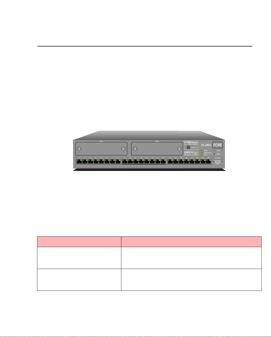
The front panel of the switch is shown below:
1589
Figure 1.1 -
The Front Panel of the ES-2810
1.2.3 Front Panel Ports
These ports are on the front panel:
Table 1.2 -
Port Function
CONSOLE port
(DB-9)
24 x 10/100Base-TX ports (RJ-45) Connects devices using Unshielded Twisted Pair (UTP)
1 - 4
Connects a PC (running a VT1 00 emulat ion), a VT100 terminal or a modem to access the built-in Local Management
program.
cabling complying to EIA 568A Category 5 or ISO/IEC
11801 Category 5 level D.
Front Panel Ports
FORE Systems ES-2810 Ethernet Switch User’s Manual
Page 29
Introduction to the ES-2810
1.2.4 Slots for Media Modules
After removing one or both of the cover plates, the modules can be inserted to expand the
functionality of the switch.
1.2.5 Front Panel LED Functions
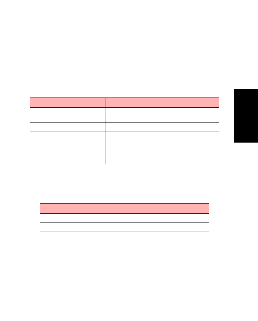
The LEDs on the front panel have the following functions:
Table 1.3 -
LED Shows the status for...
Port LEDs Green and Orange
Status The operation of the switch.
Power The internal power supply.
Temperature The internal temperature.
RPS
(redundant power supply)
Front Panel LEDs
The operation of each port.
The external, redundant power supply.
1.2.6 Buttons
The buttons on the front panel have the following functions:
Table 1.4 -
Button name Function
Port Status Shows the operational status of each port.
Reset Reset or enter Maintenance Mode or Recovery Mode
Front Panel Buttons
Introduction to the ES-
2810
FORE Systems ES-2810 Ethernet Switch User’s Manual
1 - 5
Page 30
Introduction to the ES-2810
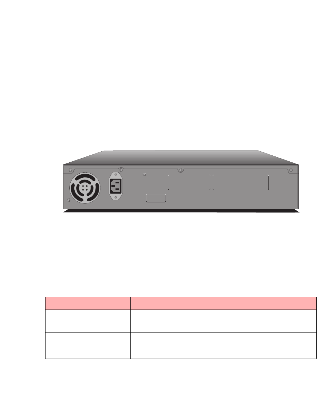
1.3 Rear Panel
1.3.1 Introduction
The rear panel has a cooling fan outlet and the main su pply cable, so you shoul d position the
switch with the rear panel facing away from you.
1.3.2 View of Rear Panel
The rear panel of the switch is shown below:
Input
100-120VAC/2A
200-240VAC/1A
47Hz-63Hz
Redundant Power Supply (RPS)
Figure 1.2 -
Rear Panel of the ES-2810
1.3.3 Rear Panel Parts
The switch’s rear panel has the following parts :
Table 1.5 -
Part Function
Fan outlet Cools the internal circuitry of the switch.
Power connection A socket to connect the power cord to the main supply.
Redundant power supply
connector
Connects an external redundant power supply. If the internal
power supply fails, the redundant power supply starts immediately.
1 - 6
Rear Panel Components
FORE Systems ES-2810 Ethernet Switch User’s Manual
1741
Page 31
Introduction to the ES-2810
1.4 Installation
1.4.1 Important
You must adhere to all local and national regulations governing the installation and connection of electrical devices when installing the switch.
1.4.2 Before Installation
1.4.2.1 Contents of the Pack
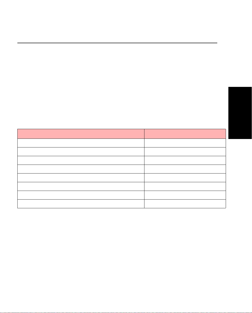
Unpack the switch carefully and check that these parts are present:
Table 1.6 -
Item Present?
One ES-2810
One power cord (suitable for your power outlet)
One mounting kit
One CD-ROM
One Console cable
One Quick Start
FORE Documentation CD (including this on-line manual)
FORE Release Notes
Package Contents Checklist
Introduction to the ES-
2810
FORE Systems ES-2810 Ethernet Switch User’s Manual
1 - 7
Page 32

Introduction to the ES-2810
1.4.2.2 Check the Package Contents
If you have not received all of the parts, or any of the parts are damaged, contact your dealer
immediately.
Keep all the packaging materials in case you need to repack the switch.
1.4.2.3 Check All Label s
Read all labels and rating plates on the switch. If there is anything that you do not understand,
or if any of the information provided does not appear to comply with your local or national
rules and regulations, consult your dealer before proceeding with the installation.
1.4.2.4 Essential Reading
It is important that you read the following:
• Warnings and the instructions earlier in this guide.
• The Release Notes included with the switch.
•The README.TXT file on the CD-ROM. This gives a general description of the
software and specific requirements.
1 - 8
FORE Systems ES-2810 Ethernet Switch User’s Manual
Page 33

Introduction to the ES-2810
1.5 Positioning and Installing the Switch
1.5.1 Allow Adequate Ventilation
The switch contains two fans to air-cool the internal circuitry. The air is drawn in from the left
of the unit and expelled through the outlet grills on the right side and the rear.
To ensure correct airflow, leave 100 mm (4 inches) free space on both sides and behind the
switch. Do not allow the intake or outlet grills to become blocked.
1.5.2 On a Desktop
To install the switch in a desktop environment:
1. Find the four rubber feet in the pack that contains the rack mounting kit.
2. Remove the backing strip from each of the four feet.
3. Attach the four rubber feet to the underside of the switch (to ensure that the switch
stands firmly).
4. Place the switch on a stable, flat surface.
5. Ensure that the air intake (on the left) and fan outlets (on the right side and rear)
are not blocked.
WARNING!
The switch’s lifetime and operational reliability
can be seriously degraded by inadequate
cooling.
Introduction to the ES-
2810
FORE Systems ES-2810 Ethernet Switch User’s Manual
1 - 9
Page 34

Introduction to the ES-2810
1.5.3 Rack Requirements
Install the switch in a stan dard rack in accordance with IEC 297 (or similar); if the minimum
outside measurements of the rack are 600 x 600mm (23.5 x 23.5 inches), you must allow
190mm (7.5inches) of space at the rear.
1.5.4 Mounting Kit
The switch is delivered with a kit to attach it to a standa rd 19-inch equipment rack (with side
support rails). The kit contains two mounting brackets and four screws (for attaching the
brackets to the sides of the switch).
1.5.5 Tools Required for Positioning in a Rack
In addition to the mounting kit, you need the following items to mount the switch in a rack:
• Standard 19-inch rack with side support rails.
• 3 mm screwdriver.
• Customer-supplied screws for securing the switch in the rack.
Mounting screws are not provided because the required sizes may vary from rack
to rack.
1 - 10
FORE Systems ES-2810 Ethernet Switch User’s Manual
Page 35
1.5.6 In an Equipment Rack
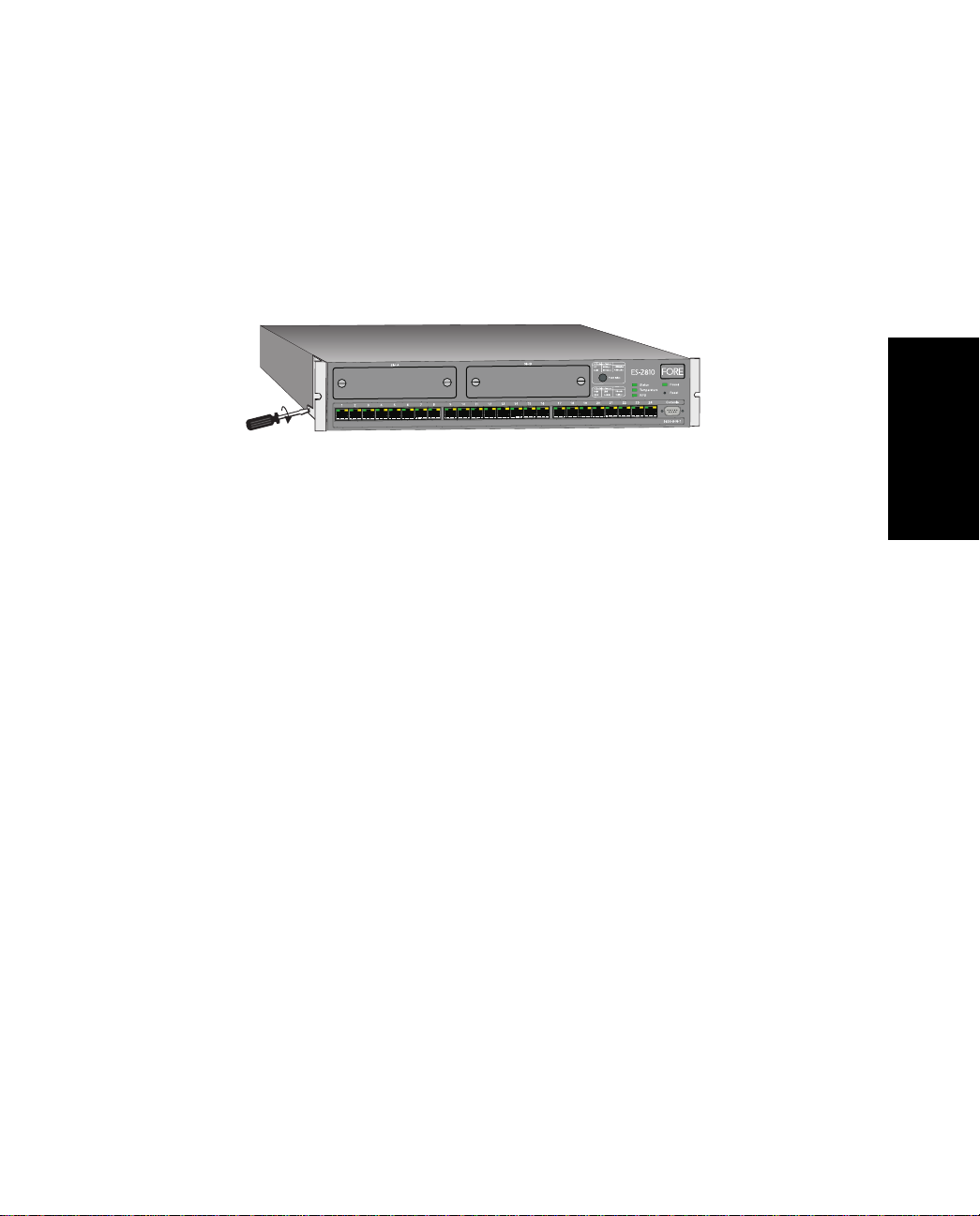
To mount the switch in a standard equipment rack:
1. Attach the mounting bracket marked “Left” to the left-hand side of the switch, and
attach the mounting bracket marked “Right ” to the right-hand side of the switch,
using the four screws provided.
Introduction to the ES-2810
Introduction to the ES-
2810
1590
Figure 1.3 -
Attaching the Mounting Brackets
Make sure that you attach the mounting bra ckets to the correct sides. Otherwise
the switch will not align correctly in the equipment rack.
2. If the four rubber feet prevent the switch from standing firmly on the equipment
rack’s side support rails, remove them.
3. Set the switch in the equipment rack, and make sure there is adequate space for air
flow around the switch (see “Allow Adequate Ventilation” on page 1-9).
4. Screw the mounting brackets securely to the equipment rack.
1.5.7 Ambient Temperature
If the switch is installed in a closed or multi-rack assembly, the operating ambient temperature
of the rack environment may be greater than the ambient temperature of the room. Make sure
that the temperature of the rack environment does not exceed the recommended operating
temperature for the switch.
FORE Systems ES-2810 Ethernet Switch User’s Manual
1 - 11
Page 36

Introduction to the ES-2810
1.6 Installing a Module
1.6.1 Introduction
You can increase the connectivity options of your switch by installing a module.
WARNING!
Modules are not designed to be installed in, or
removed from, the switch while it is in operation.
You must power off the switch before attempting
to install or remove a module.
1.6.2 Static-free Working Area
The module’s printed circuit board is an Electrostatic Sensitive Device and should be handled
only in a static-free working area; otherwise, the printed cir cuit boar d may fail or be degraded.
1.6.3 Avoiding Damage to the Circuit Board
If you remove the plate covering the slot on the front of the switch, for example, to install or
remove a module, follow this procedure to avoid damage to your printed circuit board:
WARNING!
Do not remove the plate unless the switch is
disconnected from the main power supply.
1 - 12
1. Disconnect the switch from the main power supply.
2. Ground the switch before you handle the printed circuit board.
3. Connect yourself to a non-painted/non-isolated part of the grounded switch (for
example the back panel) using a wrist strap with 1MΩ resistance to ensure that you
carry the same electrostatic charge as the enclosure.
4. Remove the plate covering the slot.
FORE Systems ES-2810 Ethernet Switch User’s Manual
Page 37

1.6.4 Installing a Module
To install a module:
1. If the switch is already operational, disconnect it from the main power supply.
2. Follow the instructions in “Avoiding damage to the circuit board” above.
3. Unscrew the screws of the plate covering the slot on the front of the switch. Save
these screws and plate.
4. Insert the module in to the slot. Place your thum bs jus t beneath t he screws on t he
front panel of the module and push in the module. Secure it using the retaining
screws.
1.6.5 Removing a Module
To remove a module:
1. If the switch is already operational, disconnect it from the main power supply.
2. Follow the instructions in “Avoiding damage to the circuit board” above.
3. Unscrew the screws securing the module.
4. Pull the module gently to disengage the connectors fully from the so cket on the
motherboard. Slide the module out completely.
5. Cover the empty module port with the plate and secure using the screws.
Introduction to the ES-2810
Introduction to the ES-
2810
FORE Systems ES-2810 Ethernet Switch User’s Manual
1 - 13
Page 38
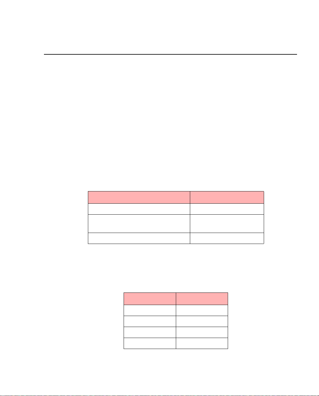
Introduction to the ES-2810
1.7 Connecting Other Devices
1.7.1 Introduction
Incorrect cabling is often the cause of network configura tion problems
1.7.2 Use Shielded Cables
Shielded cables normally comply with EMC and FCC emission limits.
Only use unshielded cables when it is explicitly specified in the installation manual of the
device in question.
1.7.3 Cables for the LAN Ports
Ports on the switch are wired MDI-X, so use the following cable:
Table 1.7 -
If you connect the switch to a... Then use a...
Workstation or server Straight-through cable 1:1
Device with MDI-X ports (for exam-
ple another switch or hub)
Device with MDI ports Straight-through cable 1:1
LAN Port Cable Requirements
Crossover cable
1.7.4 RJ-45 Connector Pin Assignments
The RJ-45 ports on the front of the switch have the following pin assignments:
Table 1.8 -
Pin number Function
1RX+
2RX3TX+
6TX-
RJ-45 Connector Pinouts
1 - 14
FORE Systems ES-2810 Ethernet Switch User’s Manual
Page 39

Introduction to the ES-2810
1.7.5 Connecting a Device to the RJ-45 Ports
To connect a workstation compatible with IEEE 802.3 (Ethernet Version 1.0 and 2.0) or a fast
access device (such as a server) to the switch’s RJ-45 ports using UTP cable (Category 5):
1. Make sure that th e device has a 100Mbps (10 0Base-FX or 10/100Base-TX) network
interface card installed.
If not, use your network interface card’s documentation to install and configure it
correctly.
2. If your workstation is fitted with an RJ-45 interface then ther e is no pr oblem. However, it is possible to attach to other connector types using an appropriate adapter.
For example, use a UTP/10Base-FL adapter for fiber connections
3. Connect one end of the UTP cable to an RJ-45 port on the switch.
According to IEEE 802.3, the cable length must not exceed 100 meters (approxi-
mately 325 feet).
4. Connect the other end to the 100Base-TX connection on the device.
1.7.6 Cable for the Console Port
If you connect a PC (via the Console Port), then use a null-modem cable.
Introduction to the ES-
2810
FORE Systems ES-2810 Ethernet Switch User’s Manual
1 - 15
Page 40

Introduction to the ES-2810
1.8 Connecting the Power
1.8.1 Introduction
After connecting the devices to the switch, connect the power cable. There are certain practical
and safety considerations to be made before powering the switch on.
1.8.2 The Power Cable
1.8.2.1 Ground Warning
The switch is delivered with a power cable that fits the power sockets in your country. If this is
not the case, contact your dealer immediately and ask for the correct power cable.
1.8.2.2 Power Cable Wiring Co lor Code
The wires in the power cable provided are color coded:
Table 1.9 -
Green and yellow Ground
Blue Neutral
Brown Live
Color Codes for Power Cable Wiring
Color Connection
1.8.2.3 I mportant for UK Use
If the colors of the wires in the power cable provided do not correspond with the markings
that identify the terminals in your plug:
1. Make sure that the green and yellow wire is connected to the terminal marked with
the letter E, or with the ground symbol , or is colored green and yellow.
2. Make sure that the blue wire is connected to the terminal marked with the letter N
or colored black.
3. Make sure that the brown wire is connected to the terminal mar ked with the letter
L or colored red.
1 - 16
FORE Systems ES-2810 Ethernet Switch User’s Manual
Page 41

Introduction to the ES-2810
1.8.3 Power Supply to a Rack
If the switch is installed in a rack, make sure the rack’s power supply socket has a ground connection and the rack is connected to a branch supply or a power supply socket with a ground
connection.
To avoid overloading the circuit and damaging the wiring of the power supply, the power
supply to the rack must be adequate to cover the extra power consumed by the switch.
Introduction to the ES-
2810
FORE Systems ES-2810 Ethernet Switch User’s Manual
1 - 17
Page 42
Introduction to the ES-2810
1.9 Power Up
1.9.1 Powering Up the Switch
Follow these steps to power up the switch:
1. Push the female end of the power cable into the main socket (in the rear panel);
plug the other end into the power supply outlet.
2. Make sure that the Power LED (on the front panel) is green.
If it isn’t green, make sure that the power outlet is working correctly (switched
on). If the power outlet is on and the Power LED is not green, then there is a fault
within the switch and you must contact your dealer.
3. V erify that an LED is lit for each of the front panel ports where a powered on device
is connected.
1.9.2 Start-up Procedure
Immediately after power-up, the following should happen during start-up:
Table 1.10 -
Stage STATUS LED... Then the switch...
1 Is red Is starting up
2 Turns to steady green Has started successfully
If the Status LED remains red, then the switch has not started successfully. Try to restart it; if
the switch does not start, contact your dealer.
Look at the other front pan el LEDs during start-up and check tha t they a r e opera ting correctly.
1 - 18
LED Indications During Start-up
FORE Systems ES-2810 Ethernet Switch User’s Manual
Page 43
1.9.3 Port LED States
The LEDs reflect the state of each port:
Introduction to the ES-2810
Table 1.11 -
LED Indicates
No lights Port enabled, no link.
Green, blinking
randomly
Green, solid Port enabled, link pulse active.
Green and Orange both blinking
randomly
Orange, solid Port disabled by management.
Green and Orange both solid Port disabled by a hardware fault, or no hardware con-
Port LED STatus Indications
Port enabled, Rx/Tx traffic, link pulse active.
Collision detected (with half duplex).
Port enabled, link pulse active.
nected.
Introduction to the ES-
2810
FORE Systems ES-2810 Ethernet Switch User’s Manual
1 - 19
Page 44

Introduction to the ES-2810
1.9.4 Default Settings After Start-up
Once the switch has star ted successfully, installa tion is complete and the switch is u sing its
default setting (also known as default configuration):
• All ports are enabled.
• All ports operate in auto-negotiation mode.
• Spanning Tree is disabled on all ports.
• Addresses that have been silent for more than 15 minutes are purged from the
switch’s address table (the MAC Address Aging time).
• No access restrictions to Local Management (Telnet).
• No SNMP restrictions.
• No permanent MAC address entries defined. A permanent entry is a MAC
address that is defined as being permitted only on a certain port. This can be a
useful security feature.
• All ports are in the same VLAN (named <System>) and VLAN mode (Standalone mode). VLANs allow you to create virtual networks using specific switch
ports, IP addresses, IP subnets and MAC addresses.
• Flow Control is enabled on all ports.
• The connection with Local Management is timed-out after 10 minutes if there has
been no input during this period.
1.9.5 After Start-up
This default configuration is adequate for simple workgroup environments to operate in basic
switching mode.
Although the switch continues to operate witho ut problems, we recommend that you ch ange
certain parameters to suit your own requirements.
Follow the instructions in Chapter 2 to change the configuration while the switch is operating.
1 - 20
FORE Systems ES-2810 Ethernet Switch User’s Manual
Page 45

Introduction to the ES-2810
1.10 Other LEDs on the Front Panel
1.10.1 Introduction
There are three other LEDs and one button on the front panel that show how the switch is
operating:
• Status LED
• Temperature LED
• Redundant Power Supply (RPS) LED
• Port Status button
1.10.2 LED Colors and their Meanings
The LEDs give information about the state of the switch:
Table 1.12 -
LED Color Meaning
Status Green Solid: The switch is operating normally.
Red Th e s wi t ch is re se t ti ng , o r ei th er ha rd wa re or so ft w are er ro r s are
Temperature Green Normal operating temperature.
Orange Temperature is higher than normal. Check that the area around
LED Indicator Colors and Meanings
Blinking (1 Hz): Updating software or running in recovery mode.
Blinking (5 Hz): Running in maintenance mode.
detected.
the air intakes and vents are clear of obstructions.
Introduction to the ES-
2810
Red Temperature is too high and the switch will shut down.
RPS Green Off: No RPS connected.
Solid: RPS connected, but not needed.
Orange Normal power supply has failed and the RPS has taken over.
FORE Systems ES-2810 Ethernet Switch User’s Manual
1 - 21
Page 46
Introduction to the ES-2810
1.10.3 Po rt Status Button
To see the speed and duplex settings of all the ports, press the Port Status button. The
function of the port LEDs changes for a period of 5 seconds, where they have the following
meaning:
Table 1.13 -
LED Color Meaning
Left (Speed) Green Off: 10Mbps
Right (Duplex) Orange Off: Half duplex
Port LED Indicator Colors and Meanings
Solid: 100Mbps
Solid: Full duplex
1 - 22
FORE Systems ES-2810 Ethernet Switch User’s Manual
Page 47

CHAPTER 2
FORE Stack View
2.1 In This Chapter
This chapter covers the topics described in Table 2.1.
Table 2.1 -
System Requirements page 2-2
Installation and Removal page 2-3
Using FORE Stack View page 2-5
Device View (Main Display) page 2-20
Explorer page 2-27
Diagnostics Window page 2-28
Trap Window page 2-30
System Window page 2-31
Errors Window page 2-32
Topics Discussed in this Chapter
Topic See Page
FORE Stack View
FORE Systems ES-2810 Ethernet Switch User’s Manual
2 - 1
Page 48

FORE Stack View
2.2 System Requirements
2.2.1 Requirements for FORE Stack View under Windows
Yo u need a PC with the following minimum requirements to run FORE Stack View:
• Microsoft Windows NT workstation or server, version 4.0, or M icrosoft Windows
95 or Microsoft Windows 98. (W indows NT 4.0 English language version workstation recommended.)
• A network adapter.
• 30 MB of free hard disk space.
• A color display with 800 x 600 resolution and 256 colors.
• The Microsoft IP protocol must be instal led and configured before installation of
FORE Stack View.
2.2.2 DHCP Limitation
Three important things to know:
• Do not use a PC running Windows NT server (with its D HCP s erver installed) to
run FORE Stack View.
• Ensure the IP address for th e PC is not ch anged by the DHCP server.
• PCs that use a network management system that uses BootP, DHCP or SNMP
Trap Receiving, may have their network management system disabled by FOR E
Stack View.
2 - 2
FORE Systems ES-2810 Ethernet Switch User’s Manual
Page 49

FORE Stack View
2.3 Installation and Removal
2.3.1 To start the installation of FORE Stack View
Normally, the Setup program for FORE Stack View will start automatically after you insert the
compact disc (CD) in your CD ROM drive. However, if it does not, use the standard Windows
procedures for installing programs. The screen shown in Figure 2.1 is displayed.
FORE Stack View
Figure 2.1 -
The Start-up Screen for FORE Stack View Ins tallation
2.3.2 To Install FORE Stack View for Windows
Click Install Windows and follow the on-screen instructions. When the installation is complete, FORE Stack View will start automatically when “Launch FORE Stack View” is selected.
FORE Systems ES-2810 Ethernet Switch User’s Manual
2 - 3
Page 50

FORE Stack View
2.4 Removal of FORE Stack View
2.4.1 Removal under Windows
To remove FORE Stack View under Windows:
1. Close all FORE Stack View programs.
2. Use standard Windows procedures to uninstall FORE Stack View.
2 - 4
FORE Systems ES-2810 Ethernet Switch User’s Manual
Page 51
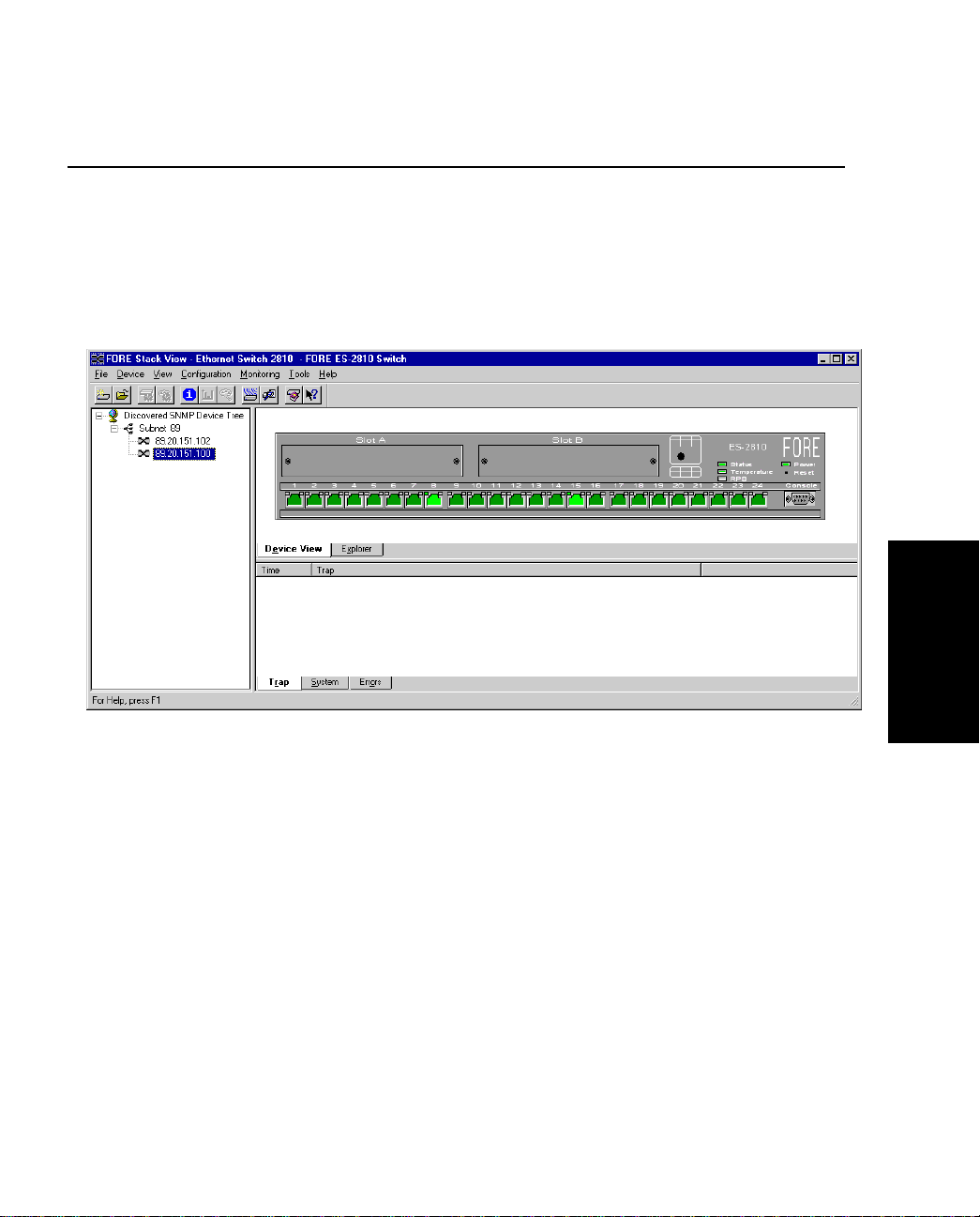
FORE Stack View
2.5 Using FORE Stack View
2.5.1 Concept
FORE Stack View uses SNMP to configure all the parameters on your switch, or group of
switches (known from here on as a stack), and monitors their activities.
FORE Stack View
Figure 2.2 -
FORE Systems ES-2810 Ethernet Switch User’s Manual
FORE Stack View
2 - 5
Page 52

FORE Stack View
2.5.2 Navigating through FORE Stack View
Many commands are available from within FORE Stack View. These are best accessed using
mouse actions. However, Windows users can also access most of them through the menu bar.
2.5.3 The FORE Stack View Window
There are three sections:
• Device Tree — displays the separate branches on your LAN, including a branch
showing all unconfigured devices.
• Interactive picture of the switch, or stack — shows the port state or the Explorer,
which provides port and VLAN details for the switch or stack .
• Information section — provides details about diagnostics, traps, errors and the
system. Using this window, you can show activity statistics f or the switch (or the
stack) and for individual ports.
2 - 6
FORE Systems ES-2810 Ethernet Switch User’s Manual
Page 53

FORE Stack View
2.6 Before a Switch is Contacted
2.6.1 Basic Menu Bar Commands
Before a switch or stack is contacted, the following commands are available through the menu
bar. The toolbar buttons are for users using FORE Stack View in Windows.
2.6.2 File Menu
The File menu contains one command, Exit, which enables you to exit the FORE Stack View.
When a switch or stack is open and the configuration has been changed and not saved to the
Flash Memory as the permanent configuration, you are asked if you want to save the new configuration before exiting.
2.6.3 Device Menu
The Device menu contains the followin g switch commands:
• Install — e nabl es yo u to in sta ll a ne w dev ice, whi ch doe s not have an IP addres s,
in FORE Stack View. Can also be accessed by selecting .
• Manage — enables a switch or stack that has an IP address already assigned to be
managed or configured. Can also be accessed by selecting .
• Discover — enables you to set up how the Device Tree discovers devices and
users.
• A list of IP addresses — contains t he last eight switches successfully contacted
from FORE Stack View. These can be used to manage the switch.
2.6.4 View menu — for Windows Users Only
The View menu allows you to customize the FORE Stack View display to your own preferences: the Toolbar and Status Bar can be switched on and off.
2.6.5 Monitoring Menu
The Monitoring menu gives access to set the Default Preferences for FORE Stack View. See
“Setting th e Preferences” on page 2-10.
FORE Stack View
FORE Systems ES-2810 Ethernet Switch User’s Manual
2 - 7
Page 54

FORE Stack View
2.6.6 Tools Menu
The Tools menu has the following commands:
• Ping — Sends ICMP echo pa ckets to the switch. Can also be accessed by selecting
.
• A Report Manager — Uploads reports, logs and the parameter block from the
switch. Can also be accessed by selecting .
• A Recovery Manager — Regains con trol of your switch if you have lost contact.
This is described in “The Recovery Manager” on page 5-36.
• A DNS-IP conversion tool converts DNS names to IP addresses.
These are described in detail, together with switch specific tools, in Chapter 5.
2.6.7 Help Menu
The Help menu has the following commands for the switch:
• Help for FORE Stack View. Can also be accessed by selecting the Help icon
then clicking on the feature of interest
• Help for switch specific topics.
2 - 8
FORE Systems ES-2810 Ethernet Switch User’s Manual
Page 55

FORE Stack View
2.7 After a Switch or Stack is Contacted
2.7.1 Commands
When FORE Stack View contacts a switch, the basic commands are supplemented with:
• Local Management access — Provides Telnet access to monitoring functions
embedded in the switch.
• RMON facility — Gathers information a bout the ne twork traffic, monitors t raffic
on subnets and enables you to define alarms on the individual ports.
• Stack Synchronization Manager (for stacks only) — Enables you to establish a
stack from a group of switches connected via a Matrix Module, or add a switch to
an existing stack and then synchronize their configurations.
• Switch Position Organizer (fo r stacks only) — Enables you t o move the switches
displayed on screen around in the stack.
• Color Code Matrix Ports (for sta cks only) — Colors the individual ports on t he
Matrix Module. This simplifies the task of tracing cables, as the ports on the Stack
Interface Modules become the same color as the corresponding Matrix Module
port.
• A color coding chart for FORE Stack View to show the states of switch’s LEDs
FORE Stack View
FORE Systems ES-2810 Ethernet Switch User’s Manual
2 - 9
Page 56
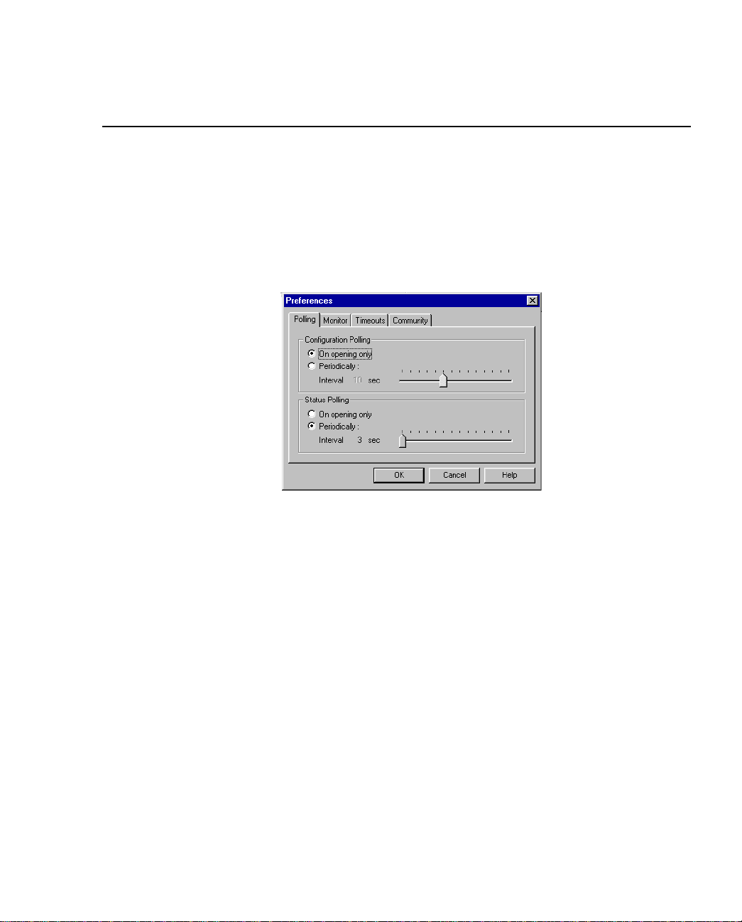
FORE Stack View
2.8 Setting the Preferences
2.8.1 Setting the Polling Intervals
The polling intervals determine how often FOR E Stack View contacts the switch or stack and
updates the status and information displayed. To change the polling parameters:
1. Select Monitoring>Preferences.
2 - 10
Figure 2.3 -
2. Click Polling or Monitor.
3. If you want the polling to happen more frequently than just on opening, click
Periodically.
4. Move the Interval slider to the required time.
5. Click OK.
Polling Tab of Preferences Dialog Box
FORE Systems ES-2810 Ethernet Switch User’s Manual
Page 57
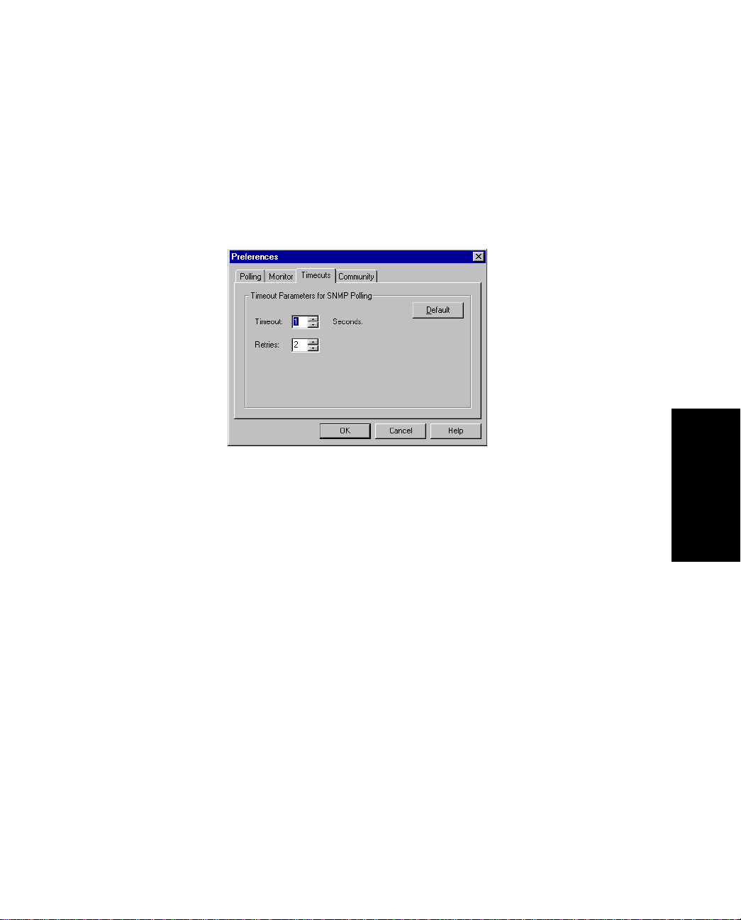
FORE Stack View
2.8.2 Setting the Timeout Parameters for SNMP
The timeout determines the intervals between polling and the number of times the request is
retried if a device is not responding. To change the timeout parameters:
1. Select Monitoring>Preferences.
2. Click Timeouts.
FORE Stack View
Figure 2.4 -
3. Change the values.
4. Click OK.
FORE Systems ES-2810 Ethernet Switch User’s Manual
Timeouts Tab of the Preferences Dialog Box
2 - 11
Page 58
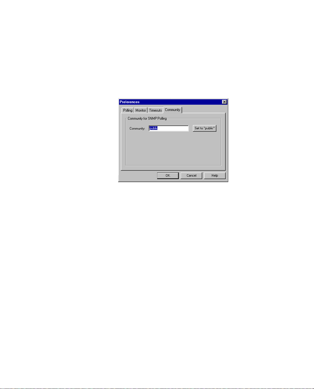
FORE Stack View
2.8.3 Setting the Community for SNMP Polling
The community for SNMP polling determines access rights. To change the community:
1. Select Monitoring>Preferences.
2. Click Community.
Figure 2.5 -
3. Type the new community name.
4. Click OK.
Community Tab of the Preferences Dialog Box
2 - 12
FORE Systems ES-2810 Ethernet Switch User’s Manual
Page 59
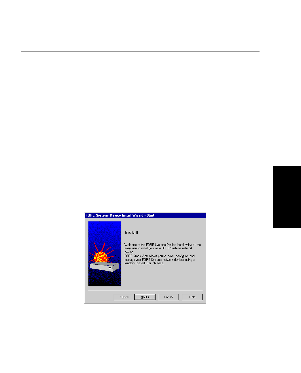
FORE Stack View
2.9 Installing and Managing Switches
2.9.1 Following Installation of FORE Stack View
After installing FORE Stack View, you can add new switches, establish or expand stacks of
switches, and manage existing switches and stacks.
2.9.2 Adding New Switches
To add new switches (that have not been assigned an IP address) to FORE Stack View, select
Device>Install. The Install Wizard will start and guide you through the installation.
2.9.3 The Install Wizard
The Install Wizard requires that you enter a minimum amount of information to set up the
switch for management by FORE Stack View. To s elect the correct new device, you need to
know the device’s MAC address. You can find this on a label on the rear panel of the device.
Yo u must assig n an IP address (and subnet mas k) to the switch on your Local Area Networ k
(LAN). FORE Stack View uses this address for configuration and management purposes.
FORE Stack View
Figure 2.6 -
FORE Systems ES-2810 Ethernet Switch User’s Manual
The Install Wizard
2 - 13
Page 60
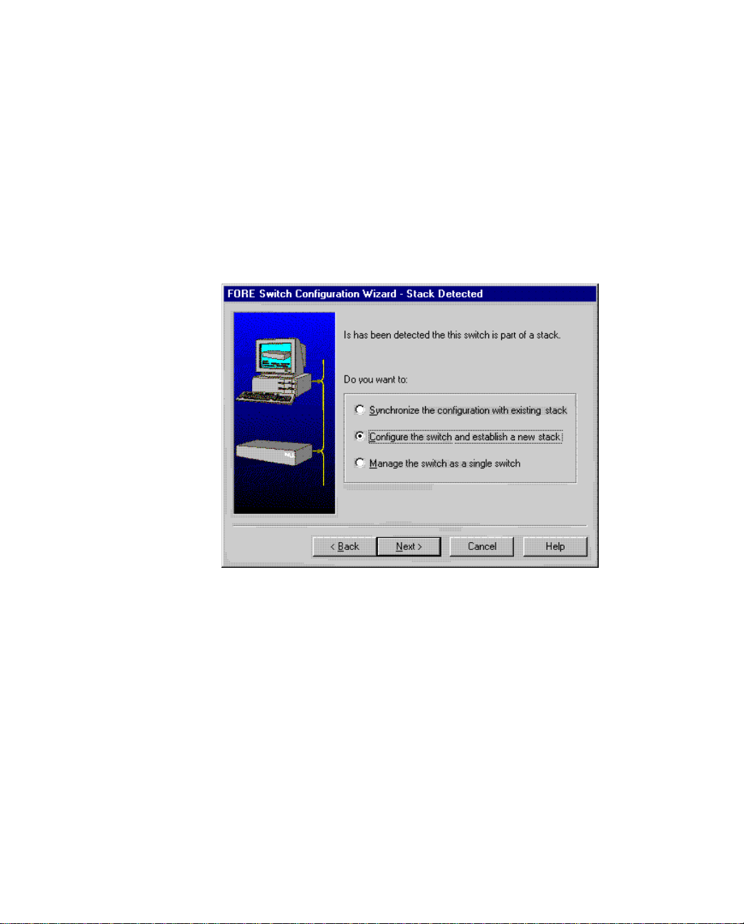
FORE Stack View
2.9.4 Matrix Module Connected to a New Switch
When the Install wizard detects that a new switch is connected to a Matrix Module, a message
(shown in Figure 2.7) informs that you must decide how to manage the switch.
• If you want to manage it separately, the installation is completed and the switch is
displayed in the FORE Stack View window.
• If you want to manage it as part of a s tack, you have the opportunity to assign
consecutive IP addresses in the next dialog.
2 - 14
Figure 2.7 -
Install Wizard New Switch Message
FORE Systems ES-2810 Ethernet Switch User’s Manual
Page 61
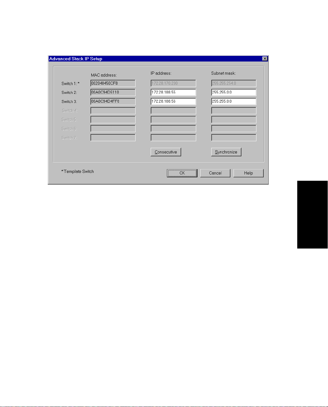
FORE Stack View
FORE Stack View
Figure 2.8 -
The Synchronization Wizard completes the installation. The complete stack, including the new
switch, then appears in the FORE Stack View window. The Synchronization wizard is
described in detail in “Stack Synchronization Manager” on page 5-40.
Advanced Stack IP Setup Dialog Box
2.9.5 Managing an Existing Switch or Stack
To manage a switch or stack that has an IP a ddress already assigned:
1. Select Device>Manage. The Manage dialog box appears.
2. Type in th e switch’s IP Address or M AC address.
3. Select the box if you want to open the switch in a new FORE Stack View window.
4. Click OK.
FORE Systems ES-2810 Ethernet Switch User’s Manual
2 - 15
Page 62
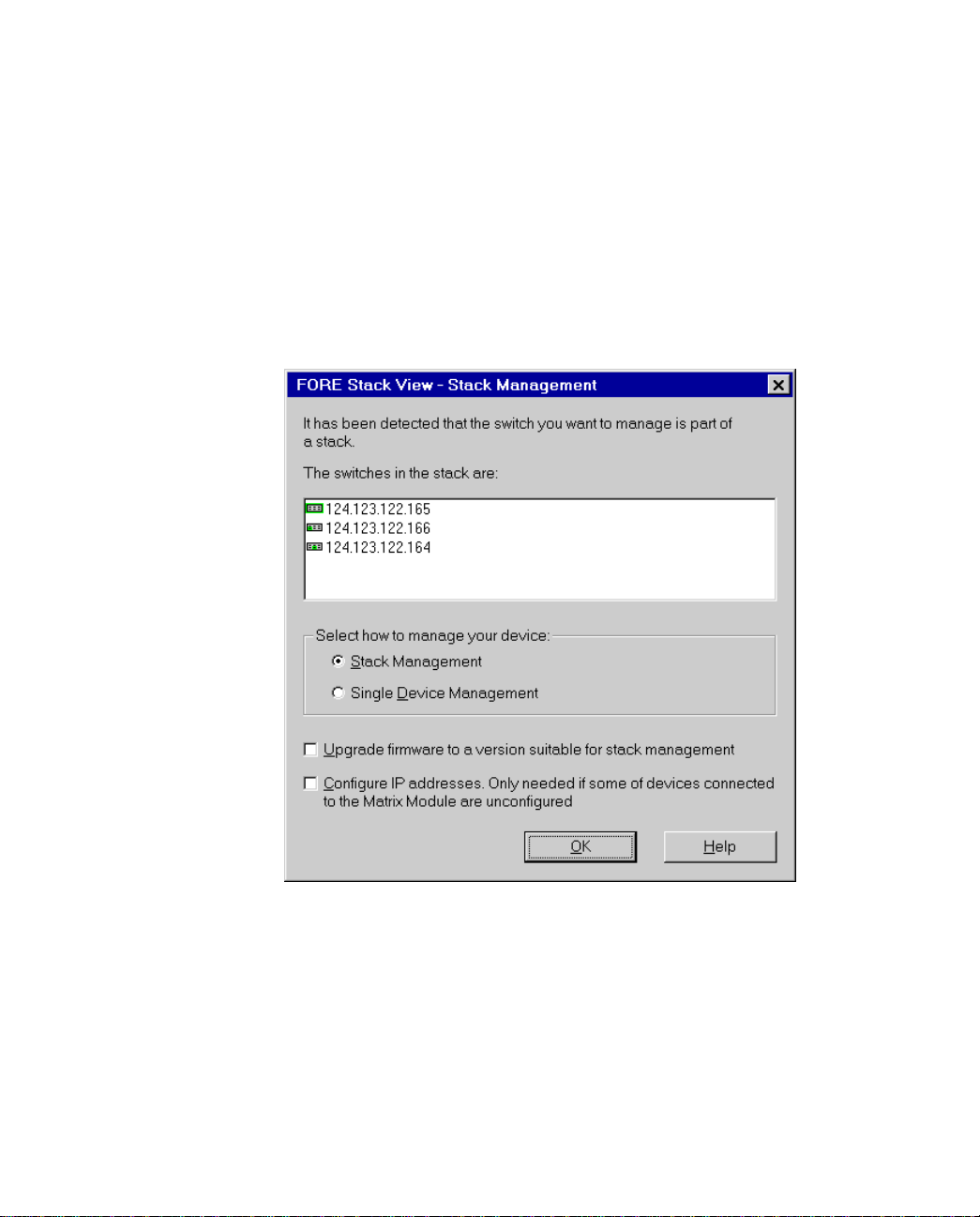
FORE Stack View
2.9.6 Establishing and Expanding a Stack
If you connect switches that already have IP addresses assigned together via a Matrix Module,
you can manage them as a stack. To create or expand an existing stack:
1. Select Device>Manage, and the Manage dialog opens.
2. Type in the IP Address or MAC address of one of the switches. All the switches
connected via the Matrix Module are displayed in this window, even switches that
are already configured as a stack.
2 - 16
Figure 2.9 -
3. If the switches don’t have compatible software, the Upgrade box is checked. If one
or more of the switches aren’t configured, the Configure IP address box is
checked.
4. Select Stack Management.
5. Select OK. The Upgrade Wizard starts automatically if software needs to be
upgraded.
The Manage Dialog Box
FORE Systems ES-2810 Ethernet Switch User’s Manual
Page 63
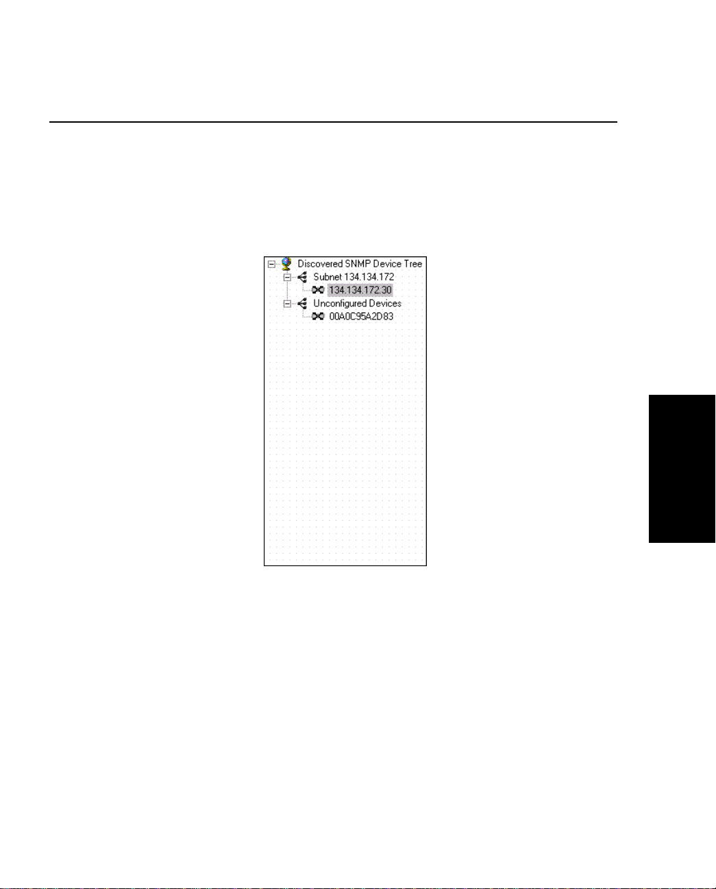
FORE Stack View
2.10 Device Tree
2.10.1 Introduction
The Device Tree displays the separate subnets on your LAN as branches in a tree. This
includes a branch that shows all the unconfigured devices on the LAN.
FORE Stack View
Figure 2.10 -
FORE Systems ES-2810 Ethernet Switch User’s Manual
The Device Tree
2 - 17
Page 64
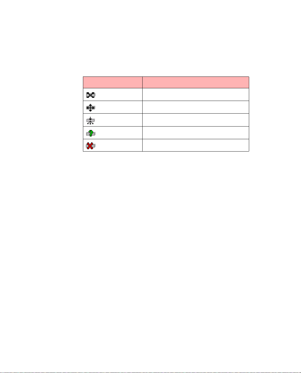
FORE Stack View
2.10.2 Identifying Devices
The Device Tree uses several icons to represent the individual devices:
Table 2.2 -
Icons Device Description
Device Icons in the Device Tree
Recognized as a switch.
Recognized as a router.
Recognized as a hub.
Device contacted, but not recognized.
Lost contact with device.
2.10.3 Installing and Managing Switches
Double clicking the switch’s IP address or MAC address opens existing switches in the FORE
Stack View window, or starts the Install Wizard for new switches.
2 - 18
FORE Systems ES-2810 Ethernet Switch User’s Manual
Page 65
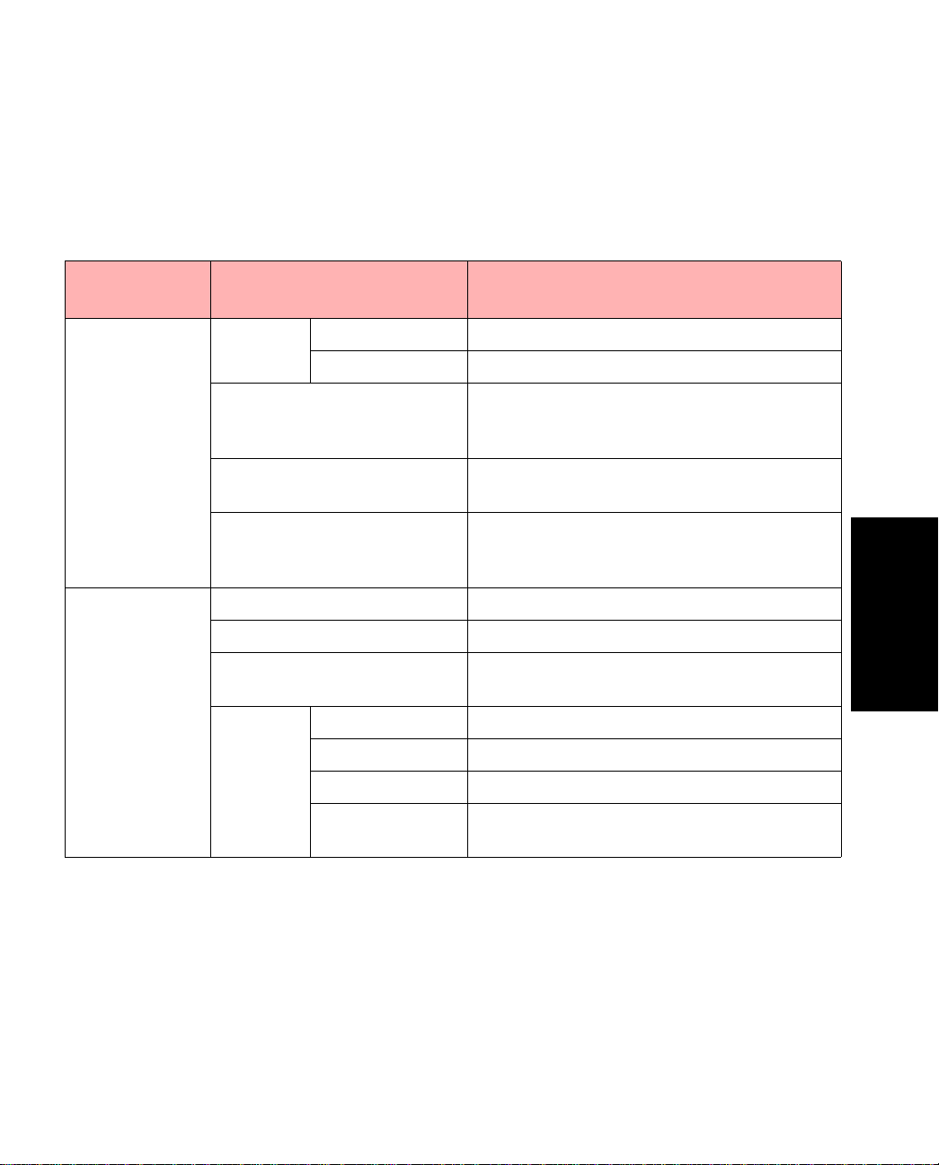
FORE Stack View
2.10.4 Right Mouse Button Commands
By positioning the mouse point er in the Device Tree and clicking the right m ouse button, the
following functions are available:
Table 2.3 -
Is a Device
Selected?
No View IP Address Sorts the devices b y their IP addresses.
Add Device If a device has not been auto-detected then
Find Locates a specific device by searching for its
Refresh Polls the network an d redisplays the tree. If a
Yes Launch With Opens the switch in FORE Stack View.
Delete Removes a device from the Device Tree.
Edit Change the name, community settings (read
RMON Statistics Provides subnet management statistics.
Right Click Command Options in the Device Tree
Available Functions Description
Name Sorts the devices by their DNS names.
you can add it to the tree. You need to know
its IP address.
IP address.
new device has been connected, it will appear
after a refresh.
and write) and polling rate of the device.
History Lists monitored traffic on a subnet.
FORE Stack View
Alarms Enables activity alarms to be set.
Logs Sets events defined by Log, Trap or Log and
FORE Systems ES-2810 Ethernet Switch User’s Manual
Trap.
2 - 19
Page 66
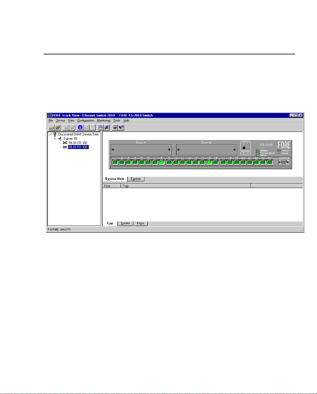
FORE Stack View
2.11 Device View (Main Display)
2.11.1 Switch Contacted
When FORE Stack View contacts the switch or sta ck, th e front (interface si de) of the swi tch or
stack is displayed.
Figure 2.11 -
This view provides a real-time view of the switch, or stack and ports, which behaves in the
same way as the physical switch. For example, the LEDs change color according to the state of
the switch/stack. You can fully manage the switch or stack using this display.
2 - 20
Switch Display in FORE St ack View
FORE Systems ES-2810 Ethernet Switch User’s Manual
Page 67

2.11.2 Mouse Actions
Using a mouse makes it easier to operate FORE Stack View and saves you time:
FORE Stack View
Table 2.4 -
Mouse action Information
Right-click switch Shows the switch-related menus for configuration and monitoring.
Right-click stack border Shows th e stack-related menus for configuration and monitoring.
Right-click a port Shows the port-related menus for configuration and monitoring.
Double left-click switch Opens the Device Setup menu.
Double left-click a port Opens that port’s S e tup menu.
Mouse Actions in FORE Stack View
FORE Stack View
FORE Systems ES-2810 Ethernet Switch User’s Manual
2 - 21
Page 68

FORE Stack View
2.11.3 Right Mouse Button Commands for a Single Switch
Right click a single switch and FORE S tack View offers:
Table 2.5 -
Functions Description
Device Setup Displays comprehensive information about the switch’s overall setup.
VLAN Setup Provides an overview of existing VLANs and the opportunity to add new
Device Information Informs you about the type of switch, its location, who is responsible for
Port Overview Gives detailed monitoring information for each port.
Device Activity Displays, in a graph format, information abo ut the activity on the ports.
VLAN Displays monito ri ng information and the status of the VLAN links.
Device Reboots the switch and provides information about the firmware in the
Configuration Ensures the swit ch’s configuration is safe by sa ving it to the flash mem-
Monitoring Provides comprehensive details for Spanning Tree statistics and RMON
Right Click Command Options for a S ingle Switch
ones or change existing ones.
it and the amount of time passed since the switch was restarted.
switch. Also enables the switch’s firmware to be upgraded.
ory, by ba cking up to disk and by being ab le to restore it again should it
be lost. If necessary, the switch can be returned to the factory default configurati on.
facilities, as well as Hardware information and an Access Overview.
2 - 22
FORE Systems ES-2810 Ethernet Switch User’s Manual
Page 69
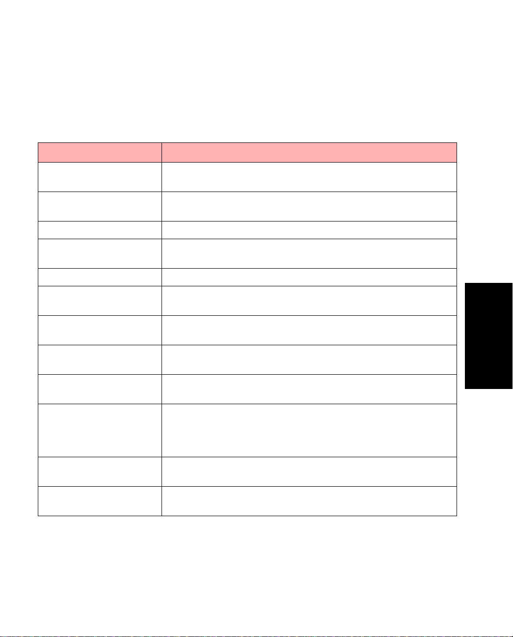
FORE Stack View
2.11.4 Right Mouse Button Commands for a Stack Border
When managing a stack of switches, right click the stack border to access the functions
described in Table 2.6.
Table 2.6 -
Functions Description
Stack Setup Displays comprehensive information about the switch’s overall
VLAN/Routing Setup Provides an overview of existing VLANs and the opportu nity to
IP Filtering Setup Defines user groups and filters the packets sent to them.
Stack Health Monitor Provides the IP addresses for all the switches in the stack, the type
IntraStack Traffic Gives information about the traffic through the Matrix Module.
System Information Gives the name and location of the stack, together with a contact
Stack Activity Displays as graphs monitoring information of traffic on the ports
Port Overview Provides port performance, packet distribution and spanning tree
Device Enables you to reboot the stack and provides information about
Configuration Ensures the stack’s configuration is safe by saving it to the flas h
Right Click Command Options for Stack Borders
setup.
add new ones or change existing ones.
of switch and whether they are responding to ping.
name and the length of time the stack has been running.
in the stack.
information for all the ports in th e stack.
the firmware in the switches.
memory, by backing up to disk and by being able to restore it again
should it be lost. If necessary, the sta ck can be returned to the factory default configuration.
FORE Stack View
Monitoring Provides Hardware information about the separate switches in the
stacks and the access rights to the devices on the LAN.
To ols Gives access to the Synchronization Ma nage, the Switch Position
Organizer and Color Code Matrix Ports function.
FORE Systems ES-2810 Ethernet Switch User’s Manual
2 - 23
Page 70

FORE Stack View
2.11.5 Right Mouse Button Commands for a Switch in a Stack
When managing a stack of switches, right click a switch to access the functions described in
Table 2.7.
Table 2.7 -
Function Description
IP and Name Setup Displays the switch’s IP address and Subnet mask.
Device Activity Displays, in a graph format, information about the activity on the ports in
the switch selected.
Spanning Tree Provides statistics about the Spanning Tree on the selected switch.
VLAN Displays monitoring information and the status of the VLAN lin ks.
Device Restarts the switch and provides information about the firmware in the
switch.
Configuration Ensures the switch’s configuration is safe by saving it to th e flash mem-
ory.
Monitoring Displays, as a graph, the activity on all the ports in the switch and RMON
facilities.
Right Click Command Options for Switches
2 - 24
FORE Systems ES-2810 Ethernet Switch User’s Manual
Page 71

2.11.6 Right Mouse Button Commands for a Port
Right click a single port to access the functions described in Table 2.8.
FORE Stack View
Table 2.8 -
Functions Description
Port Setup Displays the port status, the speed and
Add Port to VLAN Adds the port to a VLAN.
Port Details Displays comprehensive performance,
Port Activity Displays, as a graph, the activity on the
VLAN Port
Monitoring
RMON Statistics Provides RMON statistics for the
Right Click Command Options f or Ports
duplex settings, and spanning tree settings.
distribution and spanning tree details.
port.
Provides details about the MAC and IP
addresses on the VLANs.
selected port.
FORE Stack View
FORE Systems ES-2810 Ethernet Switch User’s Manual
2 - 25
Page 72
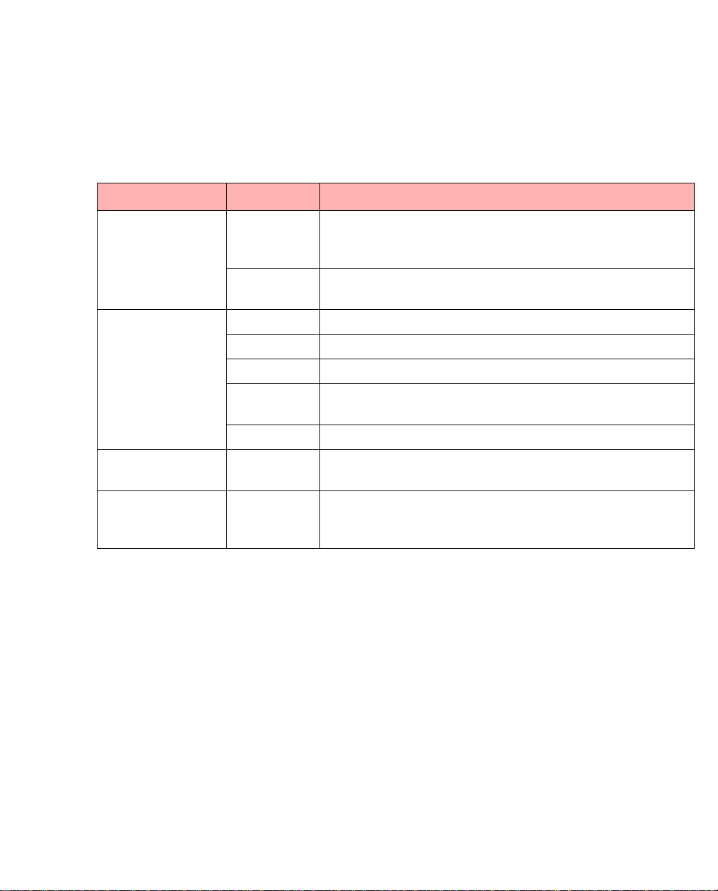
FORE Stack View
2.11.7 Color Coding
The switch and ports are displayed in different colors, as described in Table 2.9.
Table 2.9 -
Object Color Means
Switch
Body
Ports Dark green Port enabled, but no plug connected.
Stack border Dark blue The stack is selected, and various stack-specific parameters
Everything;
switches, ports and
stack border
Gray The switch is operational (the software is loaded and run-
Dark blue That switch is selected, and various device-specific parame-
Light green Port enabled and plug connected.
Brown Port disabled by management or a hardware error.
Dark blue That port is selected, and various port-specific parameters
Purple Port mirroring is enabled here.
Light blue FORE Stack View has lost contact with the devices (for
Switch and Port Display Colors
ning) and it can be contacted by FORE Stack View via the
network.
ters can be changed using the right-mouse button.
can be changed using the right-mouse button.
can be changed using the right-mouse button.
example, the switch or your PC is disconnected from the
LAN).
2 - 26
FORE Systems ES-2810 Ethernet Switch User’s Manual
Page 73
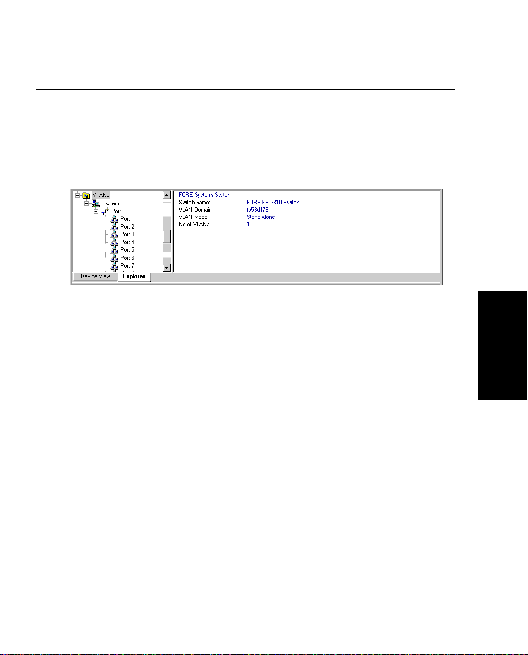
FORE Stack View
2.12 Explorer
2.12.1 FORE Stack View Expl orer
The Explorer within FORE Stack View displays management information, for example
VLANs on this switch and other switches.
Figure 2.12 -
If a switch is disabled or not operational, it is displayed with a red cross through it.
General management information for the switch is accessed from the Monitoring menu.
The FORE Stack View Explorer
FORE Stack View
FORE Systems ES-2810 Ethernet Switch User’s Manual
2 - 27
Page 74
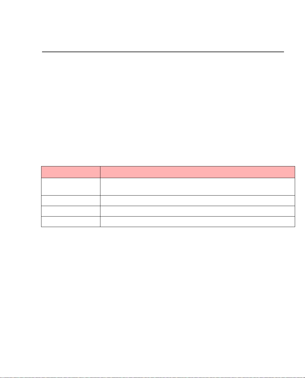
FORE Stack View
2.13 Diagnostics Window
2.13.1 FORE Stack View Diagnostics
The Diagnostics window he lps you troubleshoot the switch/s tack to get it wo rking properly
in case of problems.
The Diagnostics window lis ts any problems detected by the sw itch/stack and n otes the level
of the problem (fatal error, error or note) and the port on which the error occurred. Messages
are automatically cleared from the list when the problem no longer exists
2.13.2 Right Mouse Button Commands
Right click a message and FORE Sta c k View offers:
Table 2.10 -
Functions Description
Details Displays a diagnostic details window that describes the problem and
Refresh Reloads and updates all the diagnostic information.
Clear Clears all the messages displayed.
Use Color Coding Displays the messages in different colors, depending on their severity.
Right Click Command Options in Diagnostics Window
gives a possible solution.
2 - 28
FORE Systems ES-2810 Ethernet Switch User’s Manual
Page 75
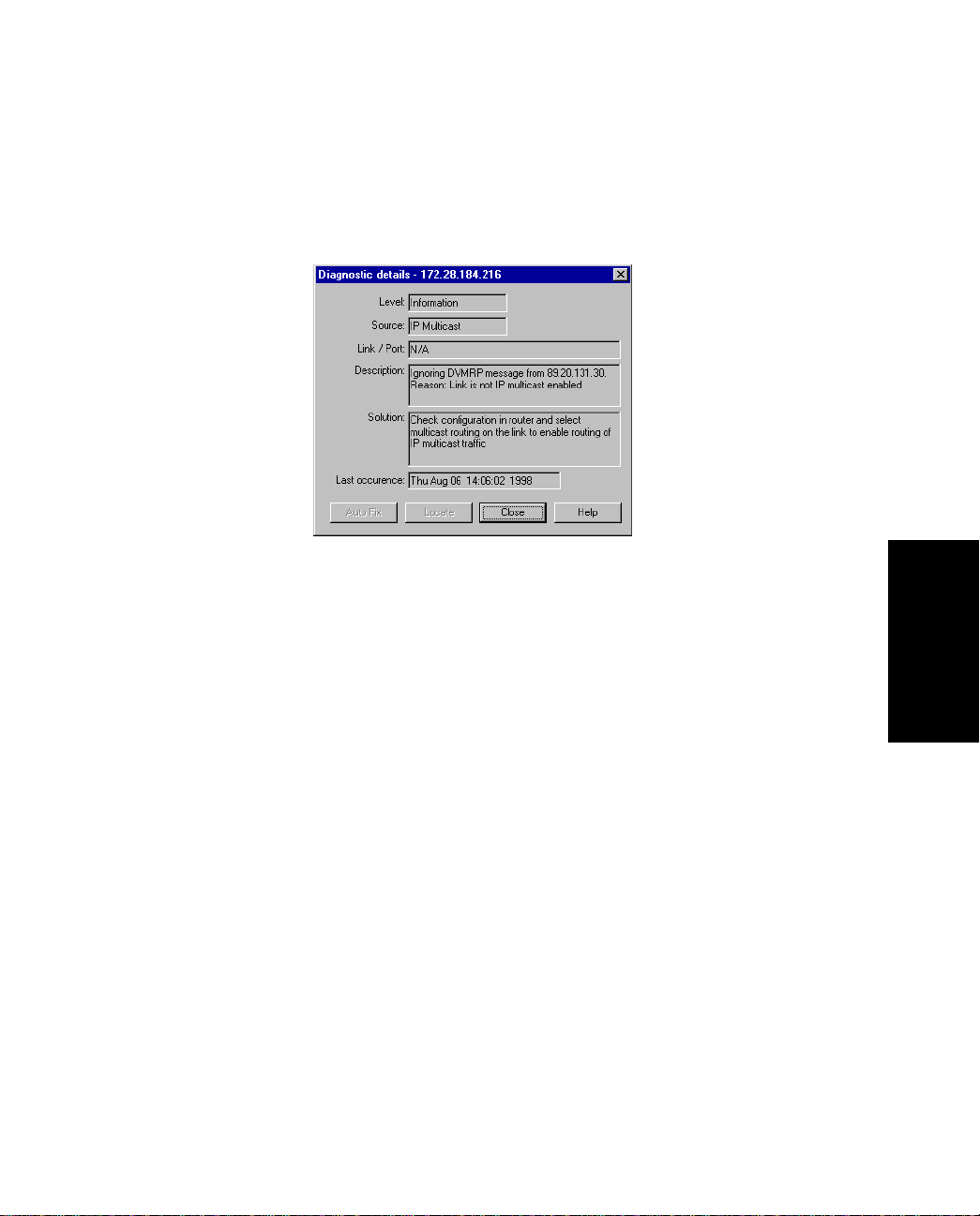
FORE Stack View
2.13.3 Diagnostic Details Window
The Diagnostic details dialog box, shown in Figure 2.13, provides comprehensive details of the
error.
Figure 2.13 -
Diagnostic Details Dialog Box
FORE Stack View
FORE Systems ES-2810 Ethernet Switch User’s Manual
2 - 29
Page 76

FORE Stack View
2.14 Trap Window
2.14.1 Traps window
The Traps window displays all traps generated by the switch.
2.14.2 Color Coding
Traps are generated by the switch for m any events, bo th no rmal and errors. Traps displayed in
FORE Stack View are color coded according to the severity of the trap.
2.14.3 Right Mouse Button Commands
Right click a message to access the funct ions described in Table 2.11.
Table 2.11 -
Functions Description
Refresh Reloads and updates all the information
Clear Clears all the messages displayed.
Properties Enables color coding to be switched on
Right Click Command Opti ons in Trap Window
in this window.
and off and define maximum number of
messages displayed.
2 - 30
FORE Systems ES-2810 Ethernet Switch User’s Manual
Page 77
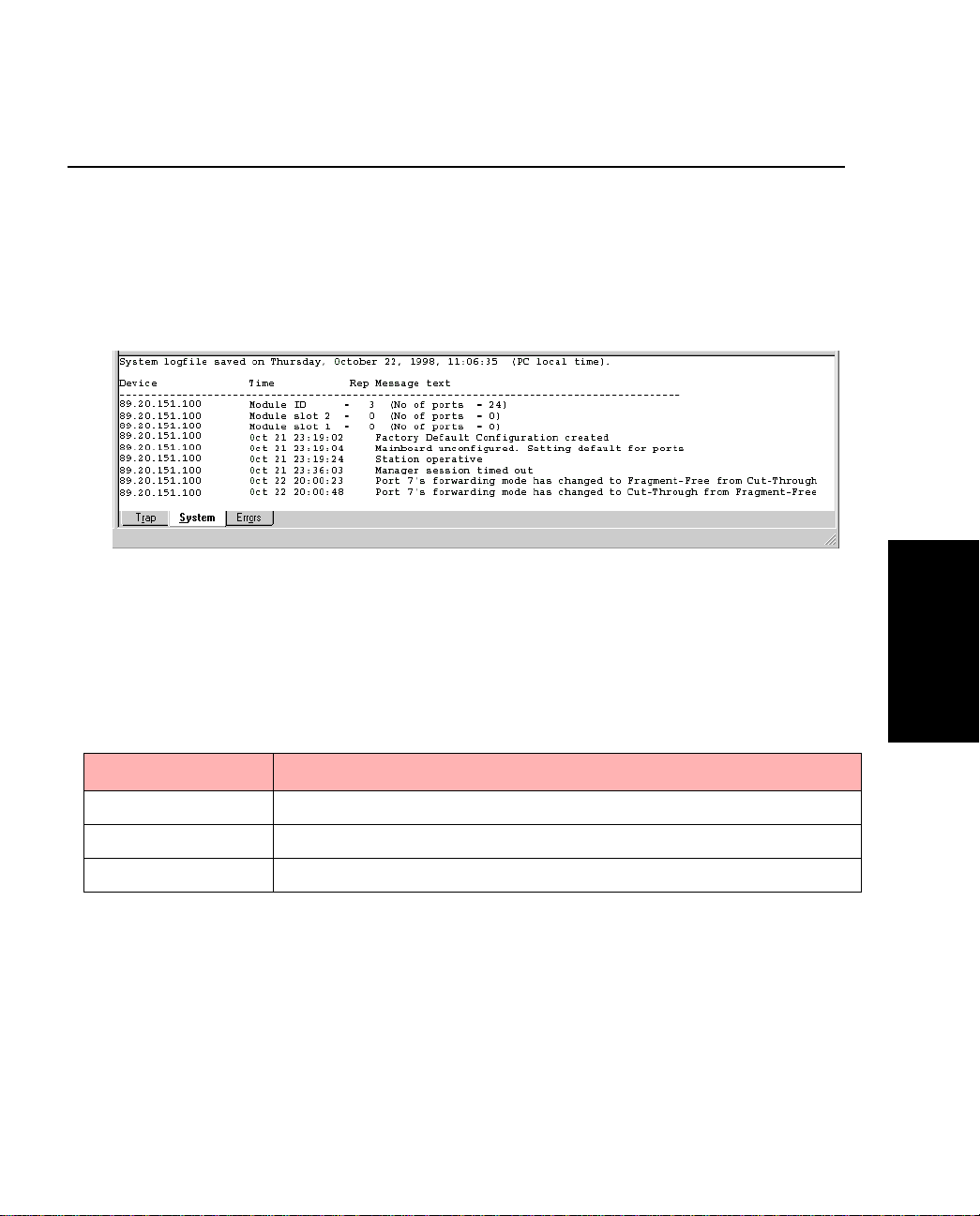
FORE Stack View
2.15 System Window
2.15.1 System Window
The System window contains a log of all the major switch events with date and times (for
example, return to factory default, filter entry settings, modules inserted in slots).
Figure 2.13 -
The System Window
FORE Stack View
2.15.2 Right Mouse Button Commands
Right click a message to access the funct ions described in Table 2.12.
Table 2.12 -
Functions Description
Refresh Reloads and updates all the information in this window.
Clear Clears all the messages displayed.
Pause Pauses the normal updating of information in this window.
FORE Systems ES-2810 Ethernet Switch User’s Manual
Right Click Command Options in System Window
2 - 31
Page 78
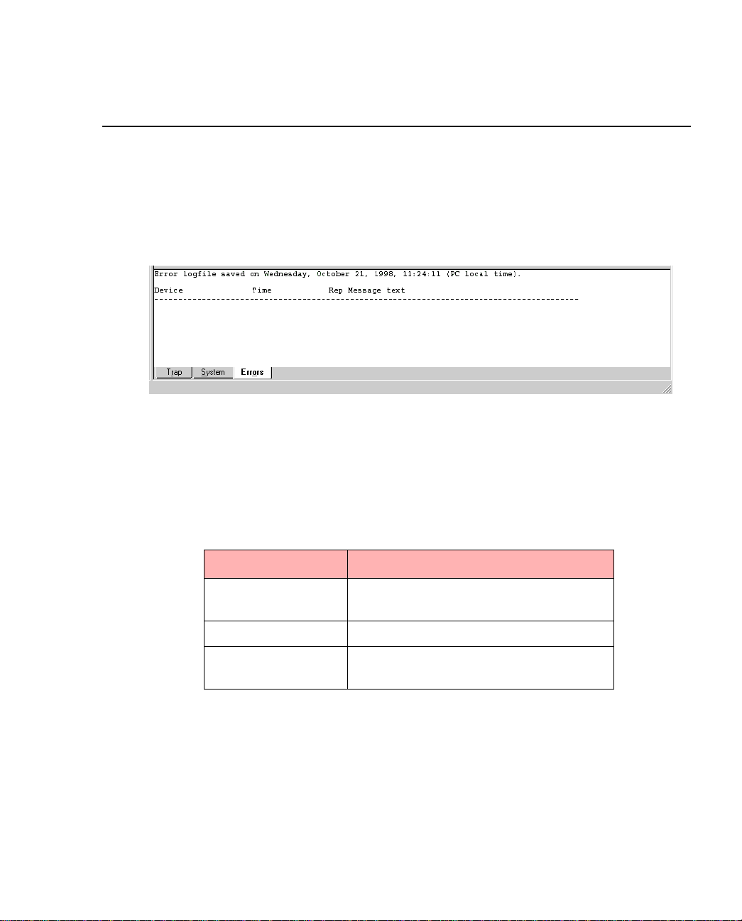
FORE Stack View
2.16 Errors Window
2.16.1 Errors Window
The Errors window, shown in Figure 2.14, is a log of all error messages generated by the
switch.
Figure 2.14 -
The Error Window
2.16.2 Right Mouse Button Commands
Right click a message to access the funct ions described in Table 2.13.
Table 2.13 -
Functions Description
Refresh Reloads and updates all the information
Clear Clears all the messages displayed.
Pause Pauses the normal updating of informa-
Right Click Command Options in Error Window
in this window.
tion in this window.
2 - 32
FORE Systems ES-2810 Ethernet Switch User’s Manual
Page 79

CHAPTER 3
Standard Configuration
3.1 In This Chapter
This chapter covers the topics described in Table 3.1.
Table 3.1 -
Changing the Setup of the Switch or Stack
Changing the Setup of the Port
Chapter 4 contains instructions on how to configure VLANs.
Topics Discussed in this Chapter
Topic
See Page
page 3-2
page 3-27
Configuration
Standard
FORE Systems ES-2810 Ethernet Switch User's Manual
3 - 1
Page 80

Standard Configuration
3.2 Changing the Setup of the Switch or Stack
3.2.1 Improving Switch Security
To restrict the use of the switch or stack, you can:
• Change the administrator password for local management.
• Change the user password for local management.
• Limit access to Local Management via the Console port and/or Telnet.
• Specify a time of “no input”, after which the connection with Local Management
is terminated.
• Change the password for moving files with TFTP.
• Specify use of TFTP.
• Restrict access to include only the stations named on the Authentications list.
3.2.2 Using the Mouse
There are two ways to access the Device Setup (for single switches) or Stack Setup window:
3 - 2
• Double-click the switch or the stack border.
• Right-click the switch or the stack border.
FORE Systems ES-2810 Ethernet Switch User's Manual
Page 81
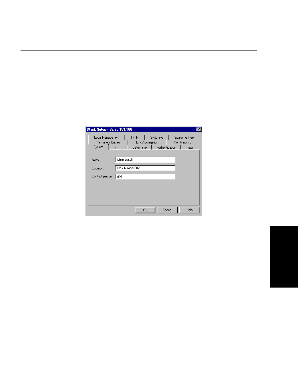
Standard Configuratio n
3.3 System Configuration
3.3.1 Identifying the Switch
To assist with switch identification and administra tion, you can chang e certain switch deta ils
(name, location and contact person). With a switch or stack in the Device View window:
1. Select Device Setup or Stack Setup.
2. Click System.
Figure 3.1 -
3. Change the details.
4. Click OK.
These details are used by SNMP management centers.
FORE Systems ES-2810 Ethernet Switch User's Manual
Stack Setup Dialog Box
Configuration
Standard
3 - 3
Page 82
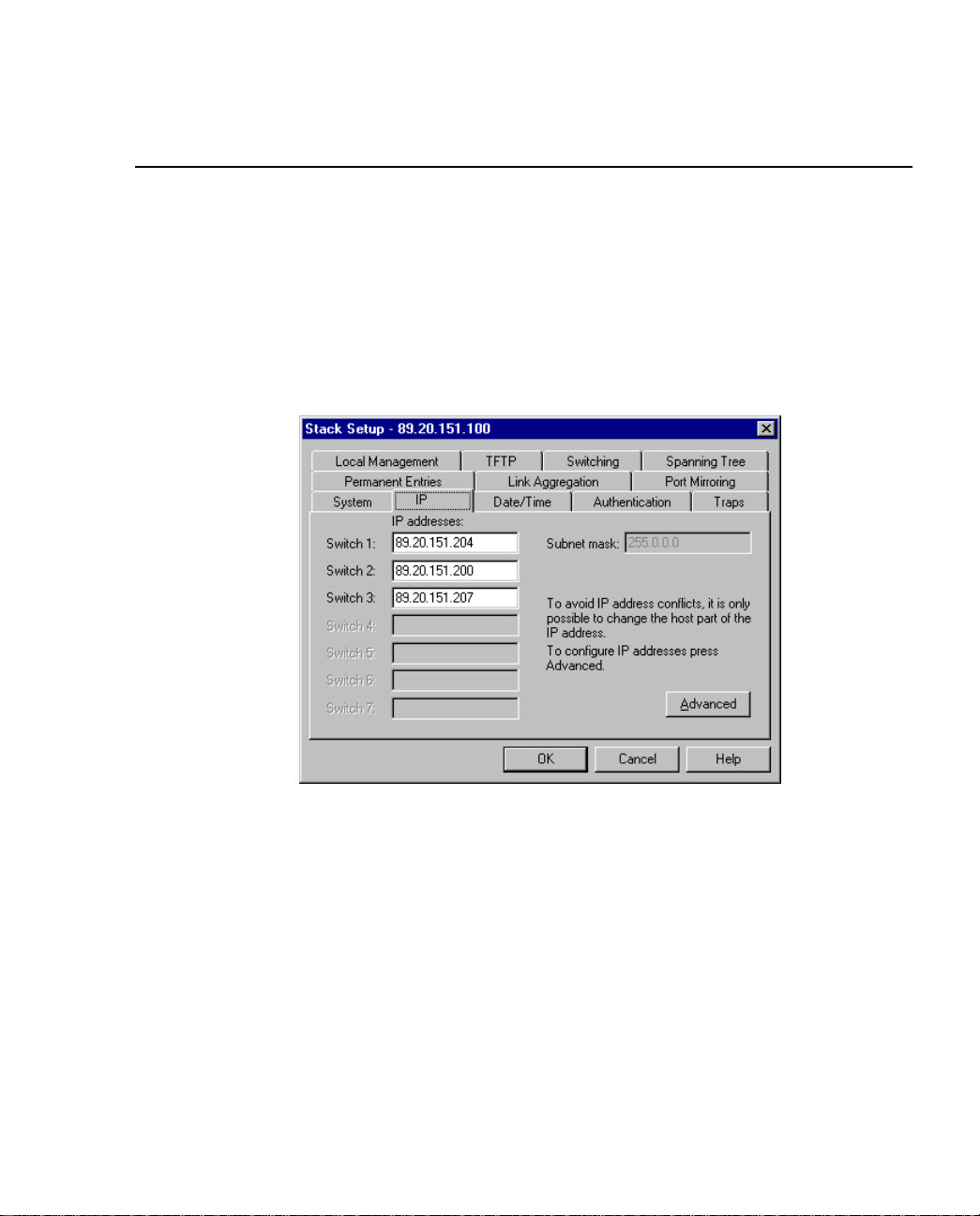
Standard Configuration
3.4 Internet Protocol Configuration
3.4.1 Changing IP Details
The IP configuration informa tion is used to co ntact the switch vi a IP protocols (TFTP, SNMP,
TELNET etc.). To change the main IP address and network mask:
1. Select Device Setup or Stack Setup.
2. Click IP.
3 - 4
Figure 3.2 -
3. Change the details.
4. Click OK.
IP Tab of the Stack Setup Dialog Box
FORE Systems ES-2810 Ethernet Switch User's Manual
Page 83
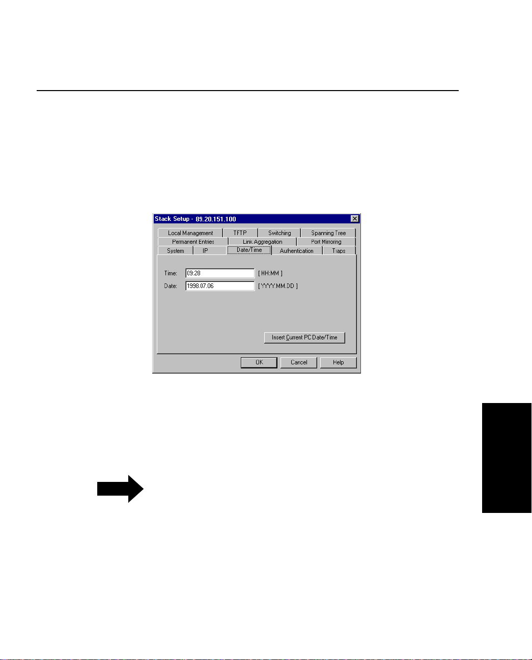
3.5 Local Time Configuration
3.5.1 Setting the Date and Clock to Local Time
To change the clock in the switch to your local time:
1. Select Device Setup or Stack Setup.
2. Click Date/Time.
Standard Configuratio n
Figure 3.3 -
3. Click Insert Current PC Date/Time to show the present settings. I f this is
satisfactory, click OK.
NOTE
4. If the time or the date is not satisfactory, click the date and/or time opt ions and
type the new time and date.
5. Click OK.
FORE Systems ES-2810 Ethernet Switch User's Manual
Date/Time Tab of the Stack Setup Dialog
The clock displays the time at which it is
accessed and not the current time.
Configuration
Standard
3 - 5
Page 84
Standard Configuration
3.6 Authentication
3.6.1 Purpose
SNMP is a fully defined, interoperative standard that helps you manage both the switch and
the network. To do this you can:
• Specify the names of the hosts to access the SNMP agent on the swi tch (authentication) by defining the source IP and community
• Specify read-write or read-only for authenticated hosts
• Request a trap to be sent if authentication is violated
If no hosts are defined in the Authentication List,
NOTE
3.6.2 Security
any host can access the SNMP agent in the
switch.
The authentications list defines the hosts that can carry out SNMP, TFTP or Telnet management on the switch, have read-write or read-only rights and access to communities. You can:
• Add a new entry to the list
• Delete an entry
• Edit existing entries
3 - 6
FORE Systems ES-2810 Ethernet Switch User's Manual
Page 85
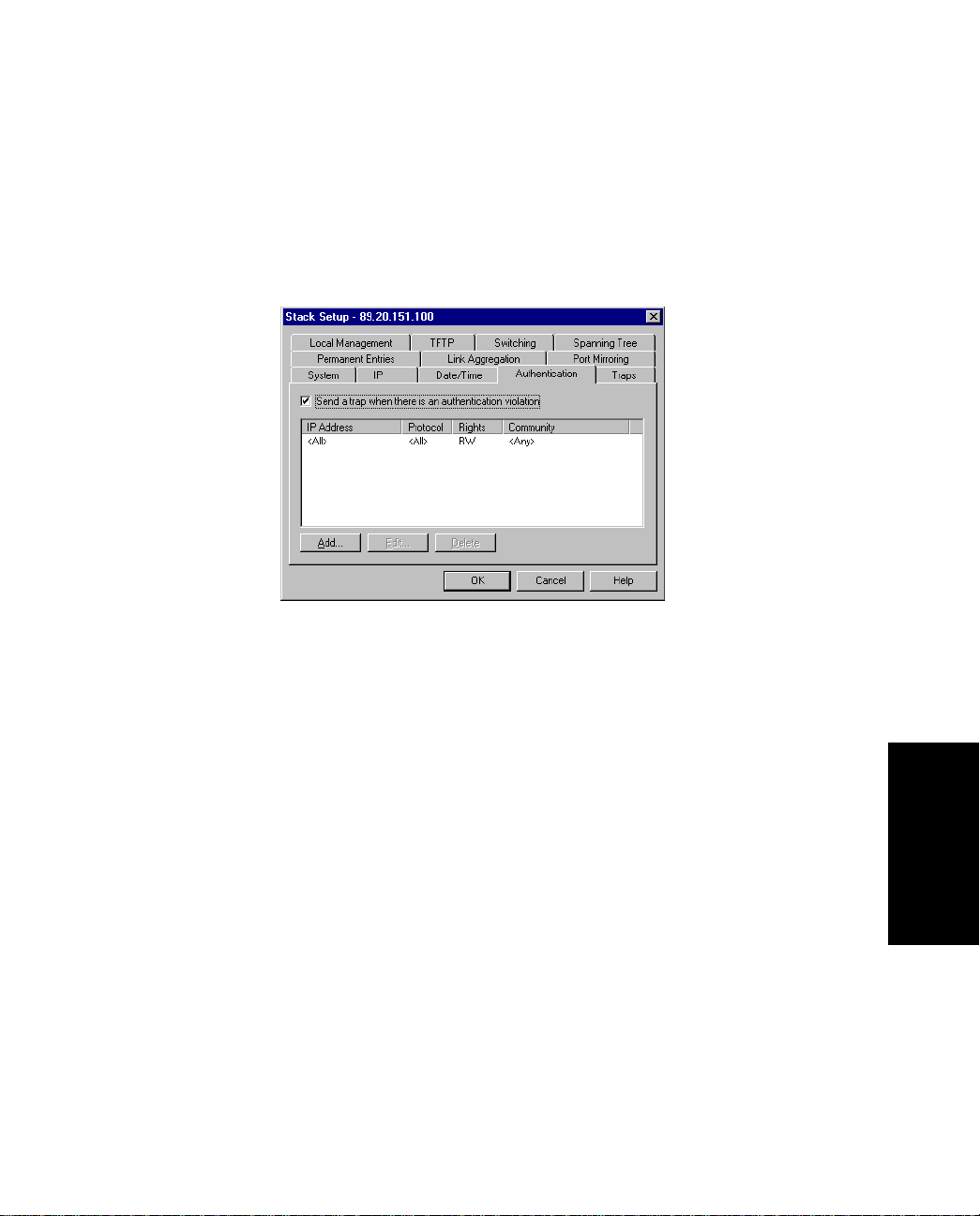
3.6.3 Adding a Device
To add a host that is allowed to carry out management on the switch:
1. Select Device Setup or Stack Setup.
2. Click Authentications.
Standard Configuratio n
Figure 3.4 -
3. Click Send trap when authentication violation.
A message will be sent to the Traps window if unauthoriz ed hosts try to carry
out management on the switch.
4. Click Add.
5. In IP address, type the IP address of the device to manage the switch.
Yo u can have a maximum of eight addresses in the list. The address 0.0.0.0 indi-
cates that all IP addresses are accepted.
6. Click Protocol and select one.
7. Click Rights and specify the level of access to the switch
8. For SNMP on ly, click Community and type the SNMP request name accepted by
the SNMP agent.
If no community name is specified, all community names are accepted by the
SNMP agent.
9. Click OK.
FORE Systems ES-2810 Ethernet Switch User's Manual
Authentication Tab of the Stack Setup Dia log Box
Configuration
Standard
3 - 7
Page 86

Standard Configuration
3.7 Traps
3.7.1 Purpose
A trap alerts you of events occurring in the switch. The traps list shows where SNMP traps
(generated by the switch) are sent. You can:
• Add a new entry to the list
• Delete an entry
• Edit existing entries
3 - 8
FORE Systems ES-2810 Ethernet Switch User's Manual
Page 87
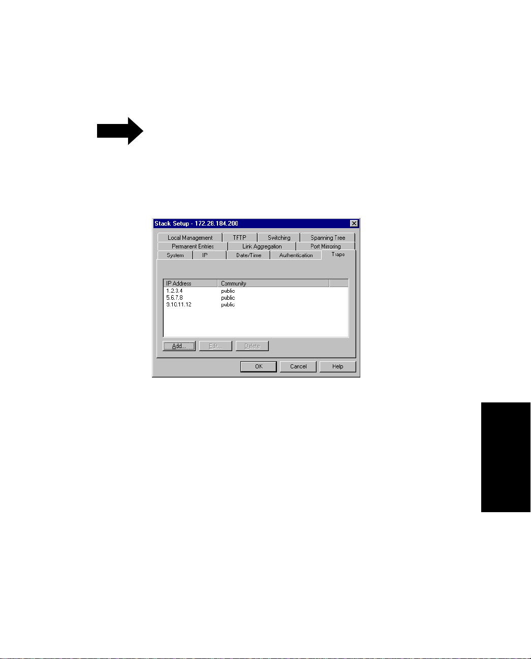
3.7.2 Adding a Trap
NOTE
1. Select Device Setup or Stack Setup.
2. Click Traps.
Standard Configuratio n
If there are no entries in the Traps list, then no
SNMP traps are sent.
Figure 3.5 -
3. Click Add.
4. Type the Destination IP address, or click This PC.
5. Type the community (SNMP password).
6. Click OK.
FORE Systems ES-2810 Ethernet Switch User's Manual
Traps Tab of the Stack Setup Dialog Box
Configuration
Standard
3 - 9
Page 88

Standard Configuration
3.8 Permanent Entries
3.8.1 Purpose
You can permanently allocate a port to a device that does not send out device information.
These devices are not removed from the switch’s address table, regardless of how long they
are quiet. This is useful for connections to printers and other similar devices. You can:
• Add a new entry to the list
• Delete an entry
• Edit existing entries
3 - 10
FORE Systems ES-2810 Ethernet Switch User's Manual
Page 89
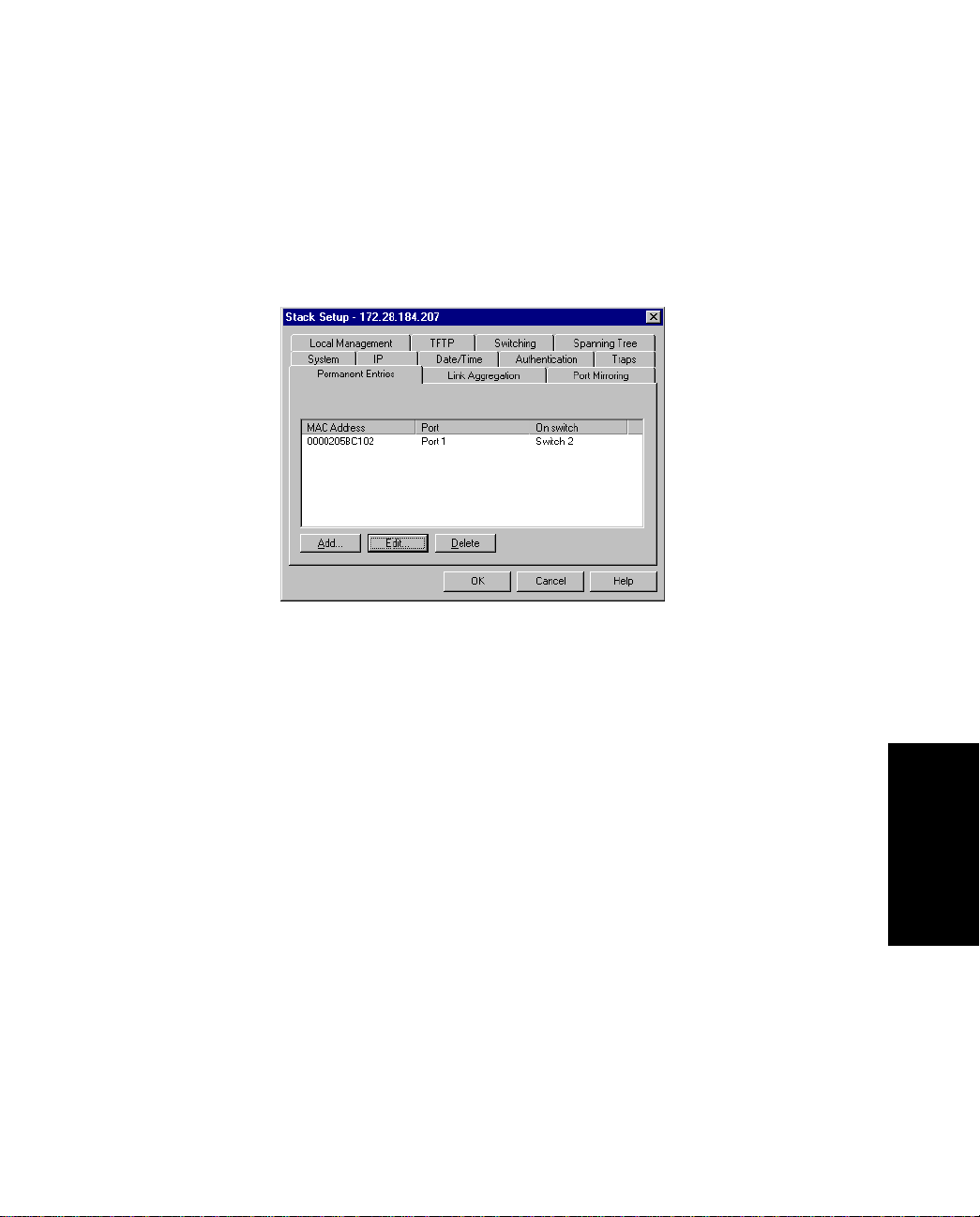
3.8.2 Adding a Permanent Entry
To add a device to the switch’s address table:
1. Select Device Setup or Stack Setup.
2. Click Permanent Entries.
Standard Configuratio n
Figure 3.6 -
3. Click Add.
4. Type the device’s MAC address.
5. Click Port number and select one. A permanent entry is only made on the
defined port.
6. Click OK.
FORE Systems ES-2810 Ethernet Switch User's Manual
Permanent Entries Tab of the Stack Setup Dialog Box
Configuration
Standard
3 - 11
Page 90
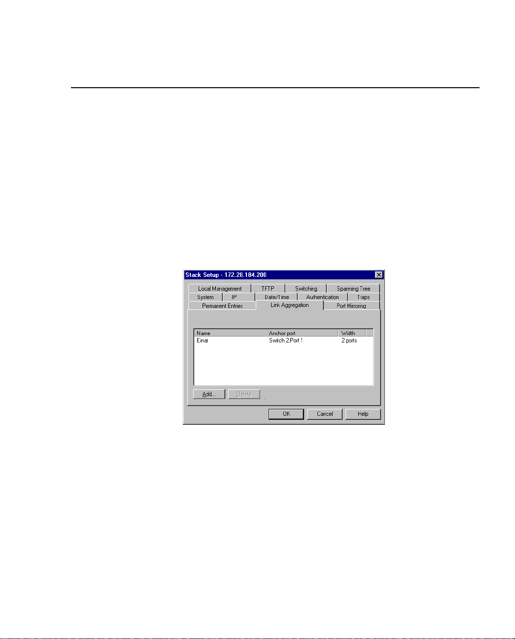
Standard Configuration
3.9 Link Aggregation
3.9.1 Purpose
Yo u can combines two or four adjacent ports to increase the bandwidth between two switches
or stacks. You can add a new entry to the list or delete an entry.
3.9.2 Adding an Aggregate Link
To set up and add an aggregate link:
1. Select Device Setup or Stack Setup.
2. Click Link Aggregation.
3 - 12
Figure 3.7 -
3. Click Add.
4. For a stack, click Switch and select one from the list.
5. Click Aggregation width: and select 2 Ports or 4 Ports.
6. Click Anchor Port and select a port.
7. Type a unique name for the link.
8. Click OK. For further configuration of a link, for example in a VLAN, use the
Anchor Port.
Link Aggregation Tab of the Stack Setup Dialog Box
FORE Systems ES-2810 Ethernet Switch User's Manual
Page 91

Standard Configuratio n
3.10 Port Mirroring
3.10.1 Purpose
The Port Mirroring function allows you to debug or monito r traffic on a specific port by duplicating the traffic and sending it to a specified port. Only one pair of ports can be mirrored per
switch. Within Port Mirroring, you can:
• Add a new entry to the list
• Delete an entry
• Edit existing entries
FORE Systems ES-2810 Ethernet Switch User's Manual
Configuration
Standard
3 - 13
Page 92
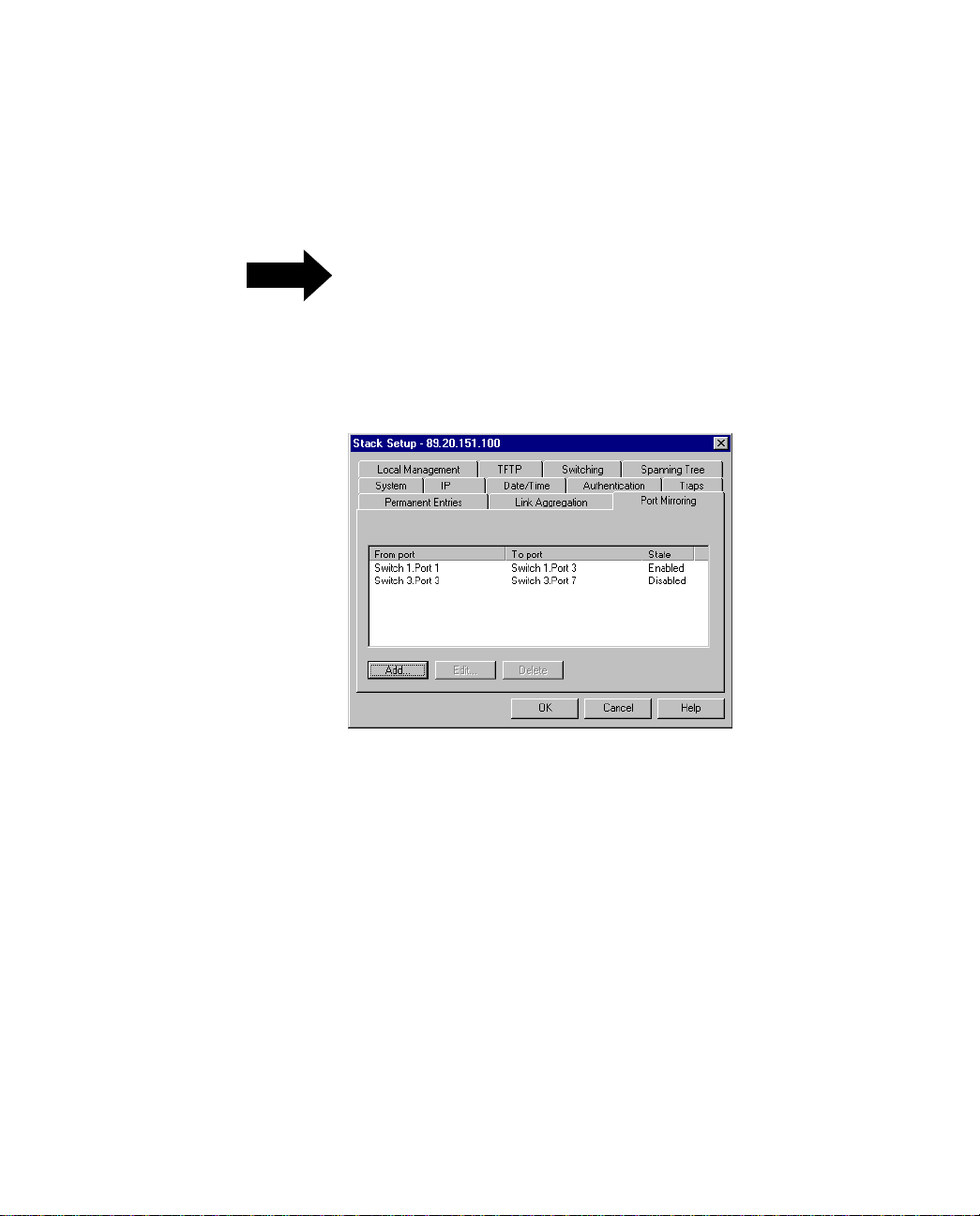
Standard Configuration
3.10.2 Adding Port Mirroring
To add a mirrored port to a switch:
If Port Mirroring is enabled, the source port will
NOTE
1. Select Device Setup or Stack Setup.
2. Click Port Mirroring.
be in store-and-forward mode. Therefore, Runts,
CRCs, etc. will not be forwarded or mirrored.
3 - 14
Figure 3.8 -
3. Click Add.
4. For a stack, click Switch and select one.
5. Click Reflect from and select the port that you want.
6. Click Reflect to and select the port to where the traffic can be
debugged/monitored.
7. Click OK.
Port Mirroring Tab of the Stack Setup Dialog Box
FORE Systems ES-2810 Ethernet Switch User's Manual
Page 93
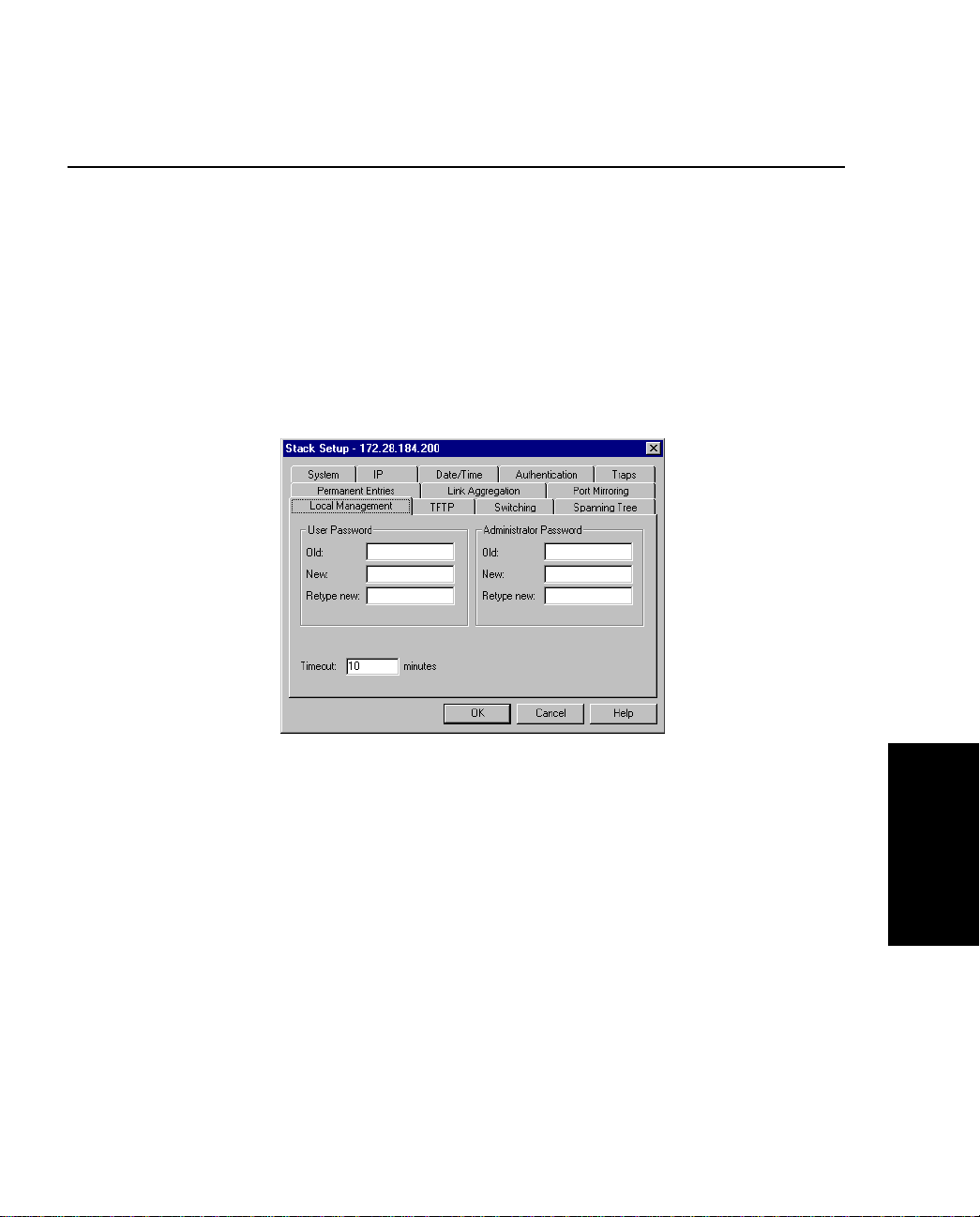
Standard Configuratio n
3.11 Local Management
3.11.1 Changing Password Details
The administrator has read-write access at all levels. The user can read the monitoring screens,
but cannot change the configuration, update software or reset the station. T o prevent unauthorized personnel changing configurations:
1. Select Device Setup or Stack Setup.
2. Click Local Management.
Figure 3.9 -
3. You can change the passwords for the Administrator and User.
4. Type the old password.
5. Type the new password.
6. Retype the new password (in Retype new).
7. Click OK.
FORE Systems ES-2810 Ethernet Switch User's Manual
Local Management Tab of the Stack Setup Dialog Box
Configuration
Standard
3 - 15
Page 94

Standard Configuration
3.11.2 Changing Timeout Details
When there has been no input during the timeout interval, the conn ection with Loca l Man agement is terminated. To change the timeout interval:
1. Select Configuration>Device Setup.
2. Click Local Management.
3. Type the new time.
4. Click OK.
3 - 16
FORE Systems ES-2810 Ethernet Switch User's Manual
Page 95

Standard Configuratio n
3.12 TFTP
3.12.1 Changing Password Details
To give added security, you can limit the number of staff authorized to transfer TFTP files by
changing the TFTP password. To change the password:
1. Select Device Setup or Stack Setup.
2. Click TFTP.
3. Type the old password.
4. Type the new password.
5. Retype the new password (in Retype new).
6. Select OK.
FORE Systems ES-2810 Ethernet Switch User's Manual
Configuration
Standard
3 - 17
Page 96
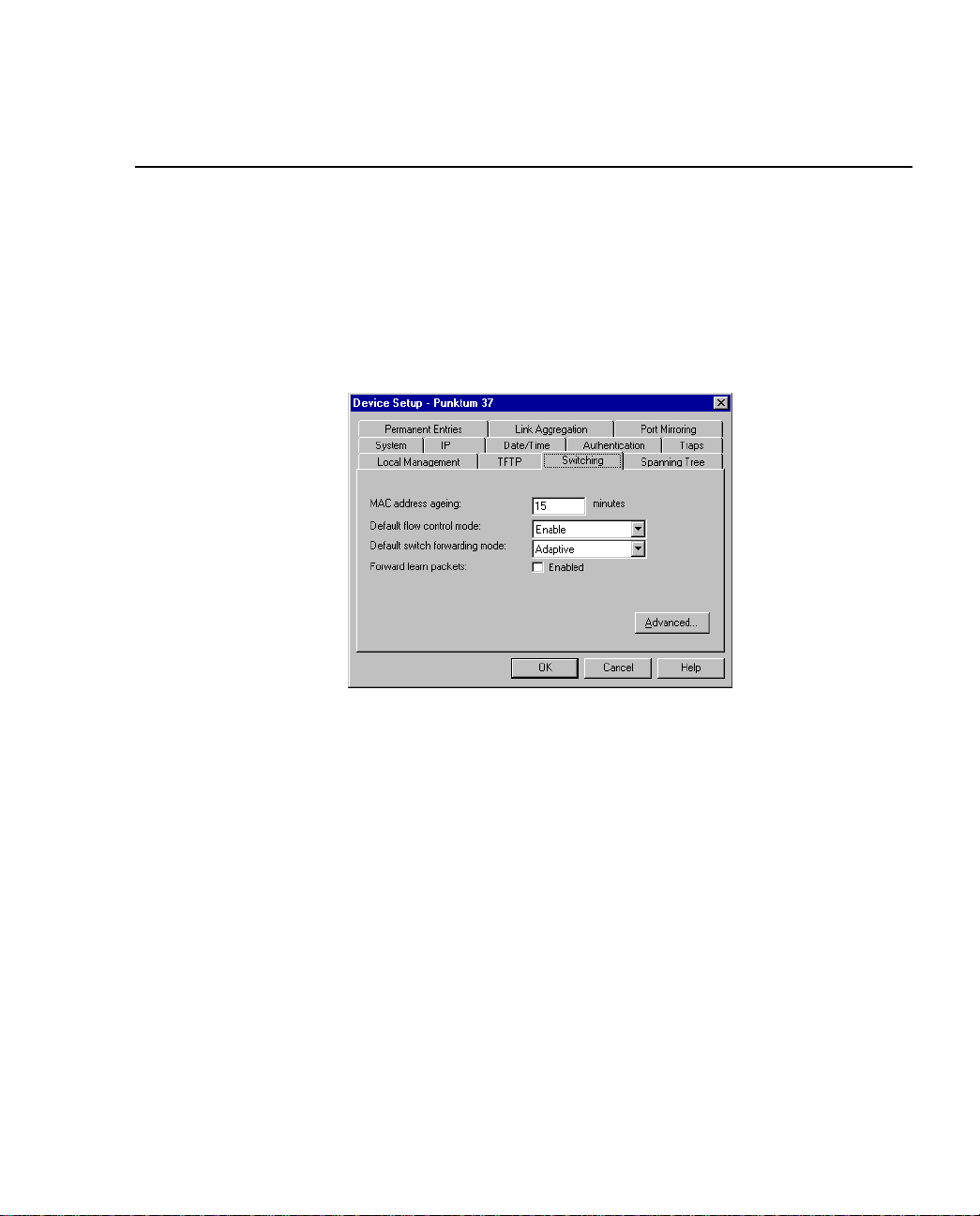
Standard Configuration
3.13 Switching
3.13.1 Changing the MAC Address Ageing Time
To change the time a MAC address is kept in the filter before being purged:
1. Select Device Setup or Stack Setup.
2. Click Switching.
3 - 18
Figure 3.10 -
3. Click MAC Address Ageing.
4. Type the required number of minutes.
5. Click OK.
Switching Tab of the D evice Setup Dialog Box
FORE Systems ES-2810 Ethernet Switch User's Manual
Page 97

Standard Configuratio n
3.13.2 Changing the Flow Control
Flow control prevents the loss of frames during busy periods. Note that the individual port
settings overrule the default setting. To change the default flow mechanism on all ports:
1. Select Device Setup or Stack Setup.
2. Click Switching.
3. Click Default Flow Control.
4. Click Enabled or Disabled.
5. Click OK.
3.13.3 Changing the Default Forwarding Mode
To change the forwarding mode to be used on all ports:
1. Select Device Setup or Stack Setup.
2. Click Switching.
3. Click Default Switch Forwarding Mode.
4. Click the default forwarding mode you want.
5. Click OK.
3.13.4 Enable Forward Learn Packets Mode
When this mode is enabled, all packets are forwarded. However, if there is not enough memory in the switch, due to heavy load, the packet is discarded. When this mode is disabled, only
“IPX Get server” request packets are forwarded. To enable or disable this mode:
1. Select Device Setup or Stack Setup.
2. Click Switching.
3. Check the box to enable this mode.
4. Click OK.
FORE Systems ES-2810 Ethernet Switch User's Manual
3 - 19
Configuration
Standard
Page 98
Standard Configuration
3.14 Adaptive Forwarding Mode
3.14.1 Purpose
You can:
• Change the Sample Time
• Define the minimum and maximum errors acceptable before changing the forwarding mode
While CRC errors and runts are the most likely
NOTE
parameters to cause the switching mode to
change, they are not the only ones.
3 - 20
FORE Systems ES-2810 Ethernet Switch User's Manual
Page 99
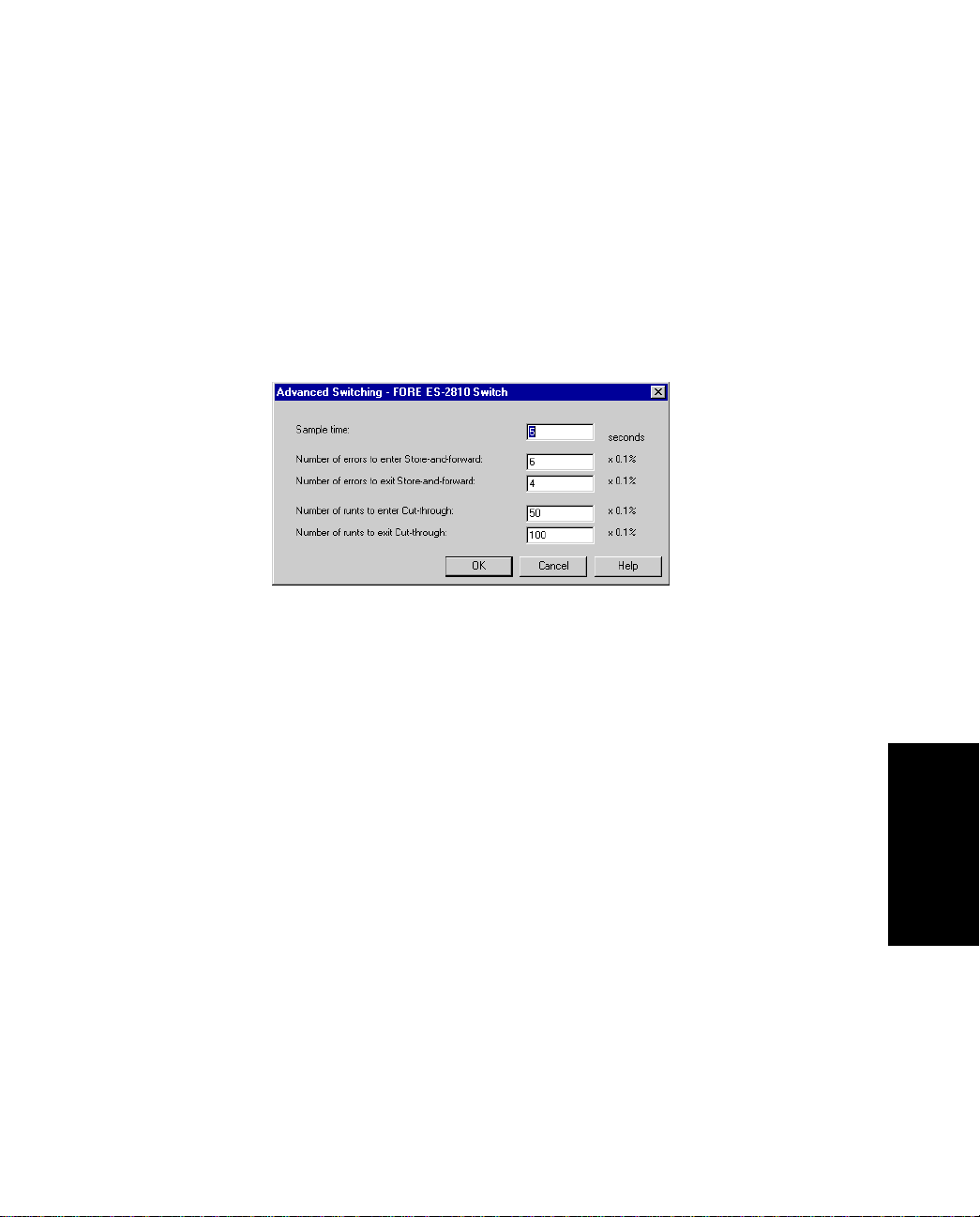
Standard Configuratio n
3.14.2 Changing the Time to Measure Errors
The sample time should be the shortest time needed to detect errors. If the sample time is too
great, there may be too many errors before the forwarding mode changes. To change the time
the switch retains error counters:
1. Select Device Setup or Stack Setup.
2. Click Switching.
3. Click Advanced.
Figure 3.11 -
4. Click Sample Time.
5. Type the required number of seconds.
6. Click OK.
FORE Systems ES-2810 Ethernet Switch User's Manual
Advanced Switching Dialog Box
Configuration
Standard
3 - 21
Page 100

Standard Configuration
3.14.3 Changing Number of Errors Before Adaptive Forwarding Mode Operates
Adaptive forwarding changes the forwarding mode depending on the upper and lower limits
of specific error types. To change the number of upper and lower limits:
1. Select Device Setup or Stack Setup.
2. Click Switching.
3. Click Advanced.
4. Click the required parameter.
5. Type the percentage of errors or runts.
6. Click OK.
3 - 22
FORE Systems ES-2810 Ethernet Switch User's Manual
 Loading...