

Page 1

Table of Contents
Introduction 3
Instrument Cluster 10
Warning and control lights 10
Gauges 13
Entertainment Systems 16
AM/FM stereo 16
AM/FM stereo with CD 18
AM/FM stereo cassette with CD 30
Climate Controls 39
Manual heating and air conditioning 39
Lights 42
Headlamps 42
Turn signal control 45
Bulb replacement 45
Driver Controls 51
Windshield wiper/washer control 51
Steering wheel adjustment 52
Power windows 53
Mirrors 53
Speed control 54
Locks and Security 63
Keys 63
Locks 63
Anti-theft system 65
Seating and Safety Restraints 72
Seating 72
Safety restraints 74
Air bags 86
Child restraints 96
1
Page 2

Table of Contents
Driving 110
Starting 110
Brakes 115
Transmission operation 118
Trailer towing 136
Roadside Emergencies 149
Getting roadside assistance 149
Hazard flasher switch 150
Fuel pump shut-off switch 150
Fuses and relays 151
Changing tires 161
Jump starting 167
Wrecker towing 173
Customer Assistance 174
Reporting safety defects (U.S. only) 182
Cleaning 183
Maintenance and Specifications 189
Engine compartment 191
Engine oil 195
Battery 200
Fuel information 207
Part numbers 231
Refill capacities 232
Lubricant specifications 235
Accessories 242
Index 246
All rights reserved. Reproduction by any means, electronic or mechanical
including photocopying, recording or by any information storage and retrieval
system or translation in whole or part is not permitted without written
authorization from Ford Motor Company. Ford may change the contents without
notice and without incurring obligation.
Copyright © 2002 Ford Motor Company
2
Page 3

Introduction
CALIFORNIA Proposition 65 Warning
WARNING: Engine exhaust, some of its constituents, and
certain vehicle components contain or emit chemicals known to
the State of California to cause cancer and birth defects or other
reproductive harm. In addition, certain fluids contained in vehicles and
certain products of component wear contain or emit chemicals known
to the State of California to cause cancer and birth defects or other
reproductive harm.
CONGRATULATIONS
Congratulations on acquiring your new Ford. Please take the time to get
well acquainted with your vehicle by reading this handbook. The more
you know and understand about your vehicle the greater the safety and
pleasure you will derive from driving it.
For more information on Ford Motor Company and its products visit the
following website:
• In the United States: www.ford.com
• In Canada: www.ford.ca
• In Australia: www.ford.com.au
• In Mexico: www.ford.com.mx
Additional owner information is given in separate publications.
This Owner’s Guide describes every option and model variant available
and therefore some of the items covered may not apply to your
particular vehicle. Furthermore, due to printing cycles it may describe
options before they are generally available.
Remember to pass on the Owner’s Guide when reselling the vehicle. It is
an integral part of the vehicle.
Fuel pump shut-off switch In the event of an accident the
safety switch will automatically cut off the fuel supply to the
engine. The switch can also be activated through sudden vibration (e.g.
collision when parking). To reset the switch, refer to the Fuel pump
shut-off switch in the Roadside emergencies chapter.
3
Page 4
Introduction
SAFETY AND ENVIRONMENT PROTECTION
Warning symbols in this guide
How can you reduce the risk of personal injury and prevent possible
damage to others, your vehicle and its equipment? In this guide, answers
to such questions are contained in comments highlighted by the warning
triangle symbol. These comments should be read and observed.
Warning symbols on your vehicle
When you see this symbol, it is
imperative that you consult the
relevant section of this guide before
touching or attempting adjustment
of any kind.
Protecting the environment
We must all play our part in
protecting the environment. Correct
vehicle usage and the authorized
disposal of waste cleaning and
lubrication materials are significant
steps towards this aim. Information in this respect is highlighted in this
guide with the tree symbol.
BREAKING-IN YOUR VEHICLE
Your vehicle does not need an extensive break-in. Try not to drive
continuously at the same speed for the first 1,600 km (1,000 miles) of
new vehicle operation. Vary your speed to allow parts to adjust
themselves to other parts.
Drive your new vehicle at least 800 km (500 miles) before towing a
trailer.
Do not add friction modifier compounds or special break-in oils during
the first few thousand kilometers (miles) of operation, since these
additives may prevent piston ring seating. See Engine oil in the
Maintenance and specifications chapter for more information on oil
usage.
4
Page 5

Introduction
SPECIAL NOTICES
Emission warranty
The New Vehicle Limited Warranty includes Bumper-to-Bumper
Coverage, Safety Restraint Coverage, Corrosion Coverage, and 7.3L
Power Stroke Diesel Engine Coverage. In addition, your vehicle is eligible
for Emissions Defect and Emissions Performance Warranties. For a
detailed description of what is covered and what is not covered, refer to
the Warranty Guide that is provided to you along with your Owner’s
Guide.
Data Recording
Computers in your vehicle are capable of recording detailed data
potentially including but not limited to information such as:
• the use of restraint systems including seat belts by the driver and
passengers,
• information about the performance of various systems and modules in
the vehicle, and
• information related to engine, throttle, steering, brake or other system
status.
Any of this information could potentially include information regarding
how the driver operates the vehicle potentially including but not limited
to information regarding vehicle speed, brake or accelerator application
or steering input. This information may be stored during regular
operation or in a crash or near crash event.
This stored information may be read out and used by:
• Ford Motor Company.
• service and repair facilities.
• law enforcement or government agencies.
• others who may assert a right or obtain your consent to know such
information.
5
Page 6

Introduction
Special instructions
For your added safety, your vehicle is fitted with sophisticated electronic
controls.
Please read the section Supplemental Restraint System (SRS)
in the Seating and safety restraints chapter. Failure to follow
the specific warnings and instructions could result in personal injury.
Front seat mounted rear facing child or infant seats should
NEVER be used in front of a passenger side air bag unless the
air bag can be and is turned OFF.
Notice to owners of pickup trucks and utility type vehicles
Utility vehicles have a significantly higher rollover rate than
other types of vehicles.
Before you drive your vehicle, please read this Owner’s Guide carefully.
Your vehicle is not a passenger car. As with other vehicles of this type,
failure to operate this vehicle correctly may result in loss of vehicle
control, vehicle rollover, personal injury or death.
Be sure to read Driving off road in the Driving chapter.
6
Page 7

Introduction
Using your vehicle with a snowplow
Do not use this vehicle for snowplowing.
Using your vehicle as an ambulance
Do not use this vehicle as an ambulance.
Your vehicle is not equipped with the Ford Ambulance Preparation
Package.
Electric vehicles
For specific information regarding the operation of your electric vehicle,
refer to the Electric Vehicle Owner’s Guide Supplement.
Middle East/North Africa vehicle specific information
For your particular global region, your vehicle may be equipped with
features and options that are different from the ones that are described
in this Owner Guide; therefore, a supplement has been supplied that
complements this book. By referring to the pages in the provided
supplement, you can properly identify those features, recommendations
and specifications that are unique to your vehicle. Refer to this Owner
Guide for all other required information and warnings.
7
Page 8
Introduction
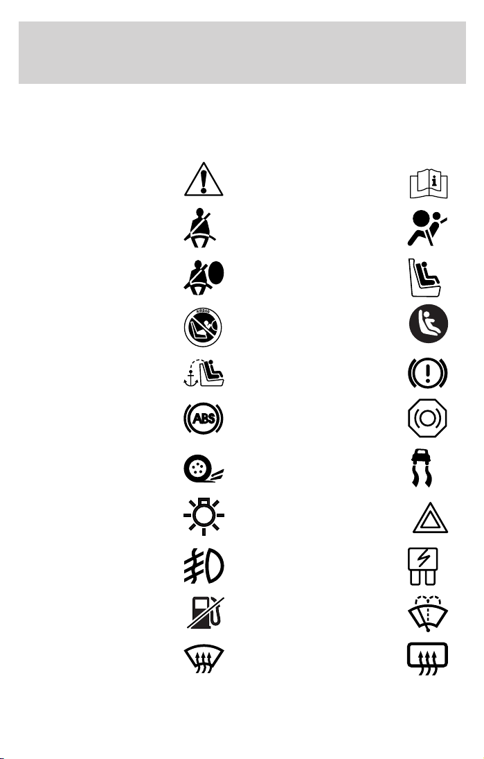
These are some of the symbols you may see on your vehicle.
Vehicle Symbol Glossary
Safety Alert
Fasten Safety Belt Air Bag-Front
Air Bag-Side Child Seat
Child Seat Installation
Warning
Child Seat Tether
Anchor
Anti-Lock Brake System
Traction Control AdvanceTrac娂
Master Lighting Switch Hazard Warning Flasher
Fog Lamps-Front Fuse Compartment
See Owner’s Guide
Child Seat Lower
Anchor
Brake System
Brake Fluid Non-Petroleum Based
Fuel Pump Reset Windshield Wash/Wipe
Windshield
Defrost/Demist
8
Rear Window
Defrost/Demist
Page 9
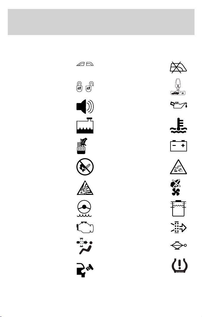
Vehicle Symbol Glossary
Introduction
Power Windows
Front/Rear
Child Safety Door
Lock/Unlock
Power Window Lockout
Interior Luggage
Compartment Release
Symbol
Panic Alarm Engine Oil
Engine Coolant
Engine Coolant
Temperature
Do Not Open When Hot Battery
Avoid Smoking, Flames,
or Sparks
Battery Acid
Explosive Gas Fan Warning
Power Steering Fluid
Maintain Correct Fluid
Level
Emission System Engine Air Filter
MAX
MIN
Passenger Compartment
Air Filter
Jack
Check fuel cap Low tire warning
9
Page 10

Instrument Cluster
WARNING LIGHTS AND CHIMES
Warning lights and gauges can alert you to a vehicle condition that may
become serious enough to cause expensive repairs. A warning light may
illuminate when a problem exists with one of your vehicle’s functions.
Many lights will illuminate when you start your vehicle to make sure the
bulb works. If any light remains on after starting the vehicle, have the
respective system inspected immediately.
Check engine: The Check Engine
indicator light illuminates when the
ignition is first turned to the ON
position to check the bulb. Solid
illumination after the engine is
started indicates the On Board Diagnostics System (OBD-II) has
detected a malfunction. Refer to On board diagnostics (OBD-II) in the
Maintenance and Specifications chapter. If the light is blinking, engine
misfire is occurring which could damage your catalytic converter. Drive
in a moderate fashion (avoid heavy acceleration and deceleration) and
have your vehicle serviced immediately.
CHECK
ENGINE
Under engine misfire conditions, excessive exhaust temperatures
could damage the catalytic converter, the fuel system, interior
floor coverings or other vehicle components, possibly causing a fire.
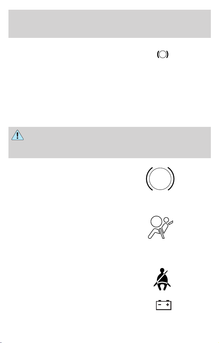
Check fuel cap: Illuminates when
the fuel cap may not be properly
installed. Continued driving with
this light on may cause the Check
Engine warning light to come on,
refer to Fuel filler cap in the Maintenance and Specifications chapter.
10
CHECK
FUEL
CAP
Page 11
Instrument Cluster
Brake system warning light: To
confirm the brake system warning
light is functional, it will
momentarily illuminate when the
ignition is turned to the ON position
when the engine is not running, or in a position between ON and START,
or by applying the parking brake when the ignition is turned to the ON
position. If the brake system warning light does not illuminate at this
time, seek service immediately from your dealership. Illumination after
releasing the parking brake indicates low brake fluid level or a failure to
brake proportioning and the brake system should be inspected
immediately by your servicing dealership.
Driving a vehicle with the brake system warning light on is
dangerous. A significant decrease in braking performance may
occur. It will take you longer to stop the vehicle. Have the vehicle
checked by your dealer immediately.
Anti-lock brake system: If the
ABS light stays illuminated or
continues to flash, a malfunction has
been detected; have the system
serviced immediately. Normal
braking is still functional unless the brake warning light also is
illuminated.
Air bag readiness: If this light fails
to illuminate when ignition is turned
to ON, continues to flash or remains
on, have the system serviced
immediately. A chime will also
sound when a malfunction in the supplemental restraint system has been
detected.
Safety belt: Reminds you to fasten
your safety belt. A chime will also
sound to remind you to fasten your
safety belt.
!
BRAKE
ABS
Charging system: Illuminates when
the battery is not charging properly.
11
Page 12

Instrument Cluster
Check gage: Illuminates when any
of the following conditions has
occurred:
• The engine coolant temperature
is high.
• The engine oil pressure is low.
• The fuel gauge is at or near empty.
Door ajar: Illuminates when the
ignition is in the ON position and
any door is open.
CHECK
GAGE
DOOR
AJAR
Overdrive off (if equipped):
Illuminates when the overdrive
function of the transmission has
been turned off, refer to the
Driving chapter. If the light flashes steadily, have the system serviced
immediately.
Four wheel drive low
(if equipped): Illuminates when
four-wheel drive low is engaged.
Four wheel drive high
(if equipped): Illuminates when
four-wheel drive high is engaged. It
may also illuminate when the 4WD
LOW is engaged, refer to the Driving chapter for more information.
Anti-theft system: Flashes when
the Securilock娂 Passive Anti-theft
System has been activated.
Speed control: Illuminates when
the speed control is engaged. Turns
off when the speed control system
is disengaged.
O/D
OFF
4WD
LOW
SPEED
CONT
12
Page 13
Instrument Cluster
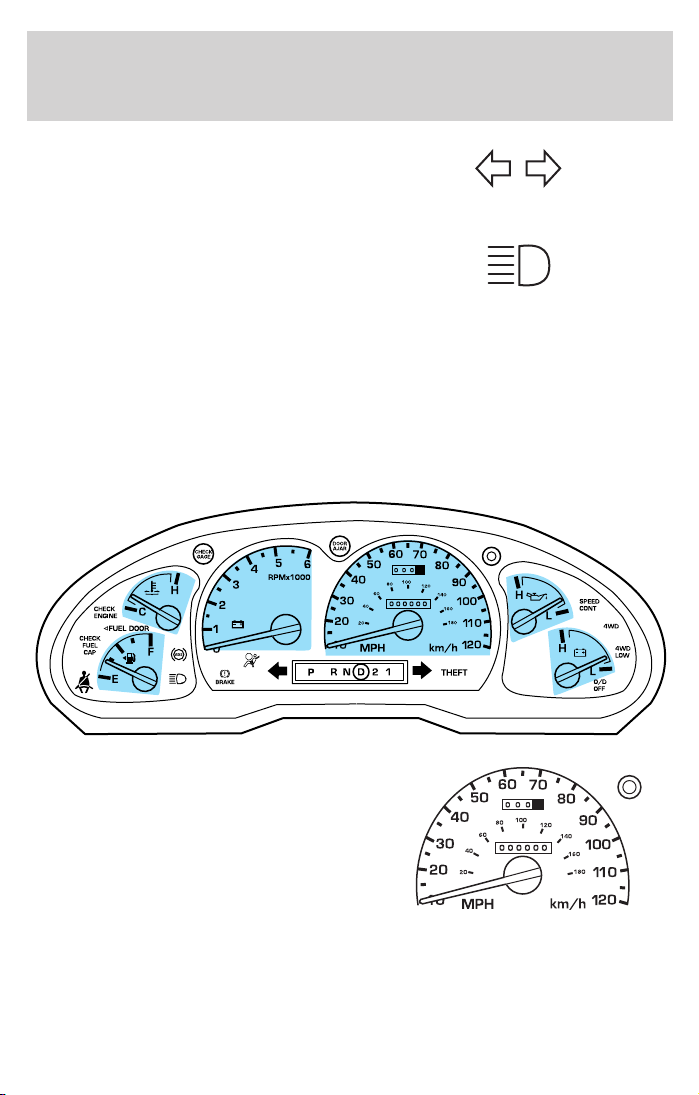
Turn signal: Illuminates when the
left or right turn signal or the
hazard lights are turned on. If the
indicators stay on or flash faster, check for a burned out bulb.
High beams: Illuminates when the
high beam headlamps are turned on.
Key-in-ignition warning chime: Sounds when the key is left in the
ignition in the OFF/LOCK or ACC position and the driver’s door is
opened.
Headlamps on warning chime: Sounds when the headlamps or parking
lamps are on, the ignition is off (and the key is not in the ignition) and
the driver’s door is opened.
GAUGES
Speedometer: Indicates the
current vehicle speed.
13
Page 14

Instrument Cluster
Engine coolant temperature
gauge: Indicates engine coolant
temperature. At normal operating
temperature, the needle will be in
the normal range (between “H” and
“C”). If it enters the red section,
the engine is overheating. Stop
the vehicle as soon as safely
possible, switch off the engine
and let the engine cool.
Never remove the coolant reservoir cap while the engine is
running or hot.
Odometer: Registers the total
kilometers (miles) of the vehicle.
H
C
Trip odometer: Registers the
kilometers (miles) of individual
journeys. To reset, depress the
control button.
Tachometer: Indicates the engine
speed in revolutions per minute.
Driving with your tachometer
pointer continuously at the top of
the scale may damage the engine.
14
20
10
30
40
50
40
20
MPH
60
60
0 0 0
100
80
0 0 0 0 0 0
70
120
km/h
80
140
90
00
1
160
180
101
20
1
Page 15

Battery voltage gauge: Indicates
the battery voltage when the
ignition is in the ON position. If the
pointer moves and stays outside the
normal operating range (as
indicated by arrows), have the
vehicle’s electrical system checked
as soon as possible.
Engine oil pressure gauge:
Indicates engine oil pressure. The
needle should stay in the normal
operating range (between “L” and
“H”). If the needle falls below the
normal range, stop the vehicle, turn
off the engine and check the engine
oil level. Add oil if needed. If the oil
level is correct, have your vehicle
checked at your dealership or by a
qualified technician.
Fuel gauge: Indicates
approximately how much fuel is left
in the fuel tank (when the ignition
is in the ON position). The fuel
gauge may vary slightly when the
vehicle is in motion or on a grade.
Refer to Filling the tank in the
Maintenance and Specifications
chapter for more information.
Instrument Cluster
H
L
H
L
15
Page 16
Entertainment Systems
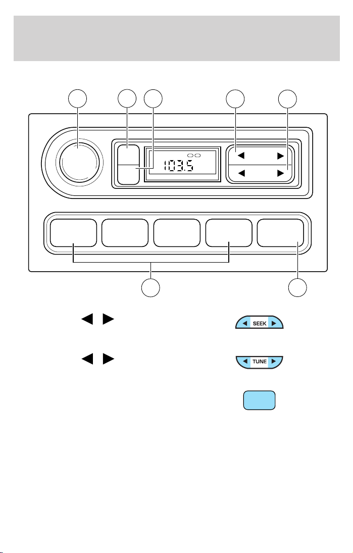
AM/FM STEREO
VOL
PUSH
ON
6
TONE
CLK
7
5
1 2 3 4 AM/FM
4
1. Seek: Press
next strong station down/up the
frequency band.
2. Tune: Press
change radio frequency down/up.
/ to find the
/ to manually
TONE VOL
ST DX
1
FM
12
SEEK
TUNE
2
3
3. AM/FM: Press to choose a
frequency band in radio mode.
16
AM/FM
Page 17
Entertainment Systems
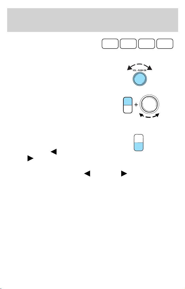
4. Memory preset buttons: To set
a station: Select frequency band
1 2 3 4
AM/FM; tune to a station, press and
hold a preset button until sound returns.
5. Power/volume: Press to turn
ON/OFF; turn to increase or
decrease volume levels.
6. Tone: Press TONE until the
desired level — Bass, Treble, Fade
appears on the display. Turn the
volume control to raise/lower the
TONE
CLK
VOL
PUSH
ON
levels, or to move the audio sound
from the right to left or the front to
back (if equipped).
7. CLK (Clock): To set the hour,
press and hold CLK until CLOCK
SET appears in the display. Press
SEEK to decrease
increase
the hours.
or
TONE
CLK
To set the minute, press and hold CLK until CLOCK set appears in the
display. Press TUNE to decrease
or increase the minutes.
17
Page 18
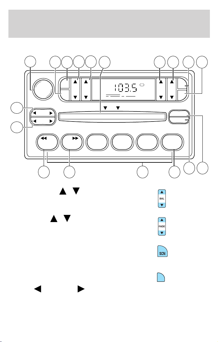
Entertainment Systems
AM/FM STEREO / SINGLE CD RADIO
12
13
VOL - PUSH ON
SEEK
TUNE
DISCS
14
16 17
15
AM
FM
BASSCDTREB BAL FADE
11
CDCD
123456
1. Balance: Press
sound to the left/right speakers.
2. Fade: Press
sound to the front/rear speakers.
/ to shift
/ to shift
18
FM1
DISC
1 234
ST
COMP
SHUFFLE
8
7910
SCN
CLK
EJ
65
3. SCN (Scan): Press to hear a
brief sampling of all listenable
stations or CD tracks. Press again to
stop.
4. CLK: To set the hour, press and
hold CLK and press SEEK to
decrease
or increase the
hours.
18
CLK
Page 19
Entertainment Systems
To set the minute, press and hold CLK and press TUNE to decrease
or increase the minutes.
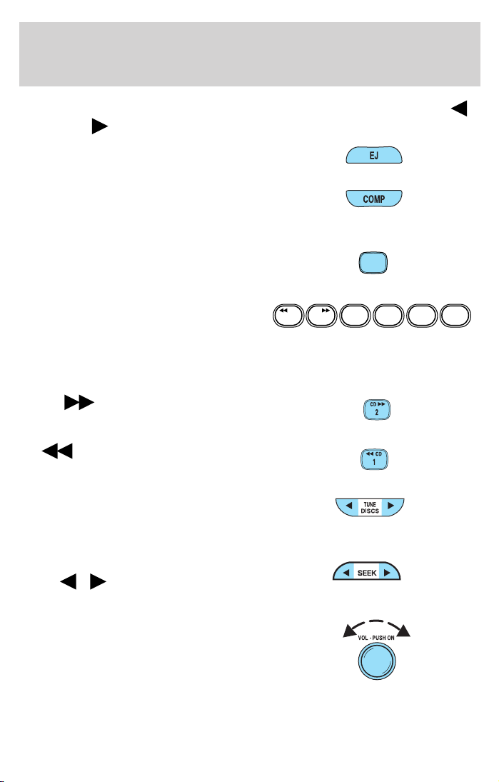
5. EJ (eject): Press to eject a CD.
6. COMP (Compression): In CD
mode, press to bring louder and
softer levels into more comfortable
listening level. The compression icon (c) will appear in the display.
7. Shuffle: Press to listen to the
tracks on the CD in random order.
Press again to turn off.
8. Memory presets: To set a
station: Select frequency band
CDCD
123456
AM/FM; tune to a station. Press and
hold a preset button until sound returns. This radio is equipped with six
station memory preset controls which allow you to set up to six AM
stations and 12 FM stations (six in FM1 and six in FM2).
9. CD:
Press and hold until
desired selection is reached.
SHUFFLE
6
SHUFFLE
10.
CD: Press and hold until
desired selection is reached.
11. Tune / Discs: In radio mode,
press to move up or down the
frequency band in individual
increments.
12. Seek: Press and release
SEEK
/ for previous/next
strong station, selection or track.
13. Power/volume: Press to turn
ON/OFF; turn to increase or
decrease volume levels.
19
Page 20
Entertainment Systems
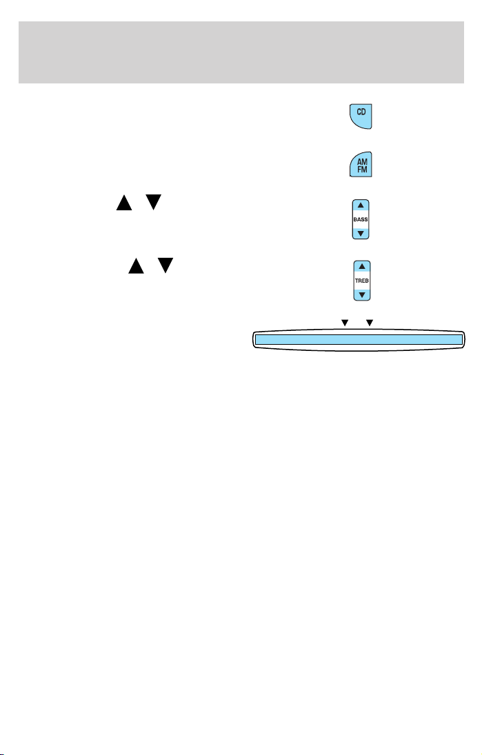
14. CD: Press to enter CD mode or
to play a CD already loaded into the
system.
15. AM/FM: Press to choose a
frequency band in radio mode.
16. Bass: Press
/ to
increase/decrease the bass output.
17. Treble: Press
/ to
increase/decrease the treble output.
18. CD door: Insert a CD printed
DISC
side up.
CD unit are designed to play
commercially pressed 12 cm (4.75 in) audio compact discs only.
Due to technical incompatibility, certain recordable and
re-recordable compact discs may not function correctly when
used in Ford CD players. Irregular shaped CDs, CDs with a
scratch protection film attached, and CDs with homemade paper
(adhesive) labels should not be inserted into the CD player. The
label may peel and cause the CD to become jammed. It is
recommended that homemade CDs be identified with permanent
felt tip marker rather than adhesive labels. Ball point pens may
damage CDs. Please contact your dealer for further information.
20
Page 21
Entertainment Systems
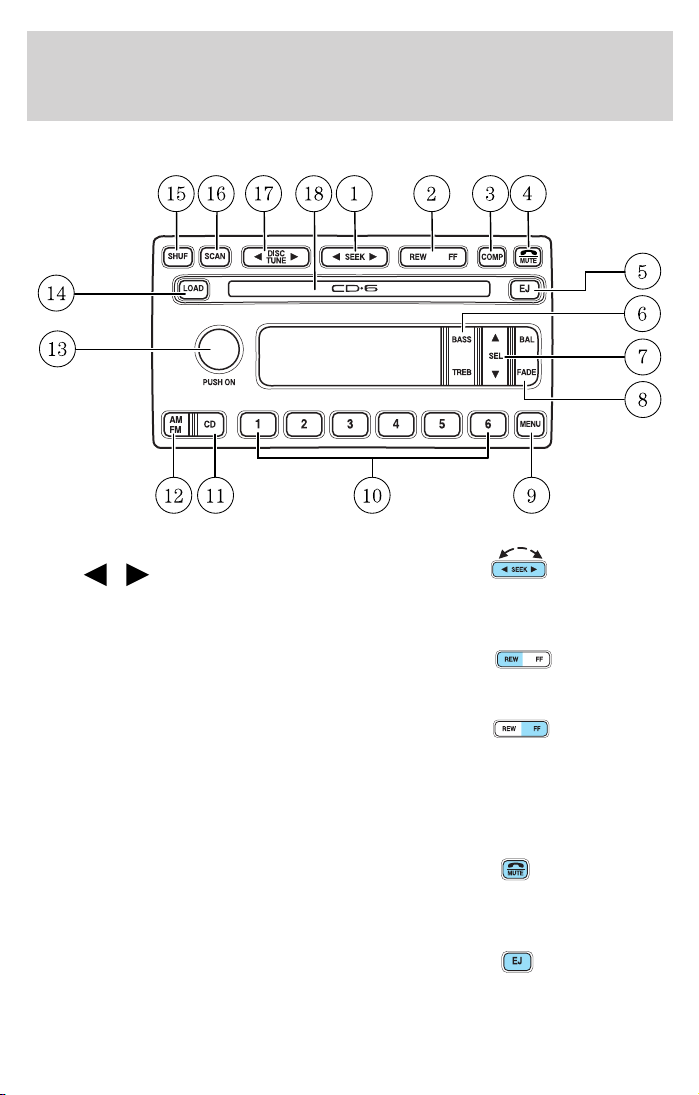
PREMIUM IN-DASH SIX CD SOUND SYSTEM
1. Seek: Press and release
SEEK
strong station, or track of current
disc.
2. Rewind: Press for a slow rewind,
press and hold for a fast rewind.
/ for previous/next
Fast forward: Press for a slow
advance, press and hold for a fast
advance.
3. Comp (Compression): In CD mode, press to adjust the soft and loud
passages together for a more consistent listening level. Press the COMP
control until COMP ON is displayed.
4. Mute: Press to MUTE playing
media; press again return to playing
media. In CD mode, MUTE acts as a
pause feature.
5. Eject: Press to eject a CD. Press
and hold to auto eject all loaded
discs.
21
Page 22
Entertainment Systems
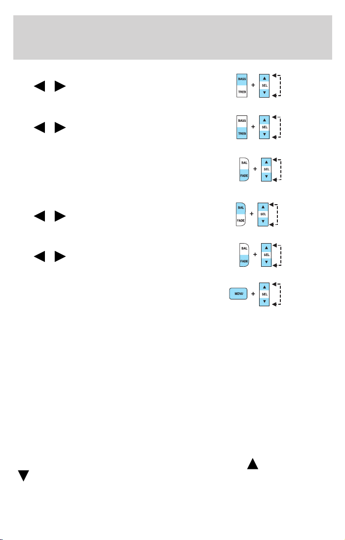
6. Bass: Press BASS; then press
SEL
the bass output.
Treble: Press TREB; then press
SEL
the treble output.
7. Select: Use with Bass, Treble,
Balance and Fade controls to adjust
levels. Use with MENU to set the
clock and engage RDS.
8. Balance: Press BAL; then press
SEL
left/right speakers.
Fade: Press FADE; then press
SEL
rear/front speakers.
9. Menu: Press MENU and SEL to
access clock mode, RDS on/off,
Traffic, Program type, Show type
and Compression modes.
Traffic: Allows you to hear traffic broadcasts. With the feature ON, press
SEEK or SCAN to find a station broadcasting a traffic report (if it is
broadcasting RDS data). Traffic information is not available in most
U.S. markets.
FIND Program type: Allows you to search RDS-equipped stations for a
certain category of music format: Classic, Country, Info, Jazz, Oldies,
R&B, Religious, Rock, Soft, Top 40.
Show TYPE: Displays the station’s call letters and format.
Compression: Brings soft and loud CD passages together for a more
consistent listening level.
Setting the clock: Press MENU until SELECT HOUR or SELECT
MINUTE is displayed. Use SEL to manually increase (
(
/ to decrease/increase
/ to decrease/increase
/ to shift sound to the
/ to shift sound to the
) or decrease
) the hours/minutes. Press MENU again to disengage clock mode.
22
Page 23

Entertainment Systems
10. Memory presets: To set a
station: Select frequency band
AM/FM; tune to a station, press and
hold a preset button until sound
returns. In CD mode, press to move between CDs.
This radio is equipped with six station memory preset controls which
allow you to set up to six AM stations and 12 FM stations (six in FM1
and six in FM2).
11. CD: Press to select CD mode.
Seamless play: In CD mode, the
transition between the end of one
CD and the beginning of another will not contain delay time unless SEEK
or a preset control is pressed.
12. AM/FM: Press to select a
frequency band in radio mode.
Autostore: Allows you to set the
strongest local radio stations without losing your original manually set
preset stations for AM/FM1/FM2 . Press and momentarily hold AM/FM.
AUTOSTORE will flash on the display. When the six strongest stations
are filled, the station stored in preset 1 will begin playing. If there are
less than six strong stations, the system will store the last one in the
remaining presets. Press again to disengage.
13. Power/volume: Press to turn
ON/OFF; turn to increase or
decrease volume levels.
14. Load: Press to load a CD. Press
and hold to load up to six discs.
15. Shuffle: Press to play tracks in
random order. Press SHUF to cycle
through SHUF DISC (if equipped),
SHUF TRAC or SHUF OFF.
16. Scan: Press to hear a brief
sampling of all listenable stations or
CD tracks. Press again to stop.
23
Page 24

Entertainment Systems
17. Disc/Tune: Radio: Press
or to manually tune down or up
the frequency band.
CD: Press
18. CD door: Insert a CD label side
up.
MACH姞 MP3 AUDIO SYSTEM
or to select the previous or next track on the CD.
1. Balance: Press
sound to the left/right speakers.
2. Fade: Press
sound to the rear/front speakers.
3. Scan: Press to hear a brief
sampling of all listenable radio
stations, CD or MP3 tracks. Press
again to stop.
24
/ to shift
/ to shift
Page 25
4. CLK: To set the clock press and
hold the CLK control for the
following functions:
Entertainment Systems
• To set the hour, press SEEK
to the hours.
• To set the minutes, press TUNE DIR
the minutes.
Release CLK to save the clock settings. Press CLK again to return the
display to radio mode.
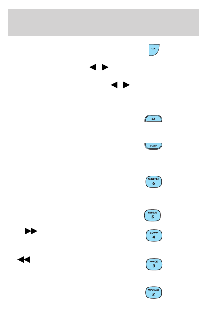
5. EJ (Eject): Press to stop and
eject a disc. If a disc is ejected and
not removed, the player will
automatically reload the disc and return to radio mode.
6. COMP (Compression): In CD
and MP3 mode, press to adjust the
soft and loud sounds together for a
more consistent listening level. The compression icon (c) will illuminate
in the display.
7. Shuffle: Press to engage random
play on the CD or MP3 disc. SHF
then ON will briefly appear in the
display. Press SEEK to select another random track on the disc. Press
shuffle again to disable.
8. Repeat: Press to repeat the
current track.
9. CD
and hold until the desired selection
point is reached. This function is
not enabled in MP3 mode.
10.
hold until the desired selection
point is reached. This function is
not enabled in MP3 mode.
11. MP3 directory: Allows you to
listen to songs in MP3 flat file mode
and MP3 directory mode.
(Fast forward): Press
CD (Rewind): Press and
/ control to decrease or increase
/ to decrease or increase
25
Page 26
Entertainment Systems
• Insert a MP3 disc to engage in the flat file mode. The MP3 icon will be
displayed.
• While in the MP3 flat file mode, press the MP3 DIR control to enter
into the directory mode. Press the TUNE DIR control to change
directories. The MP3 icon and the DIR icon will be displayed.
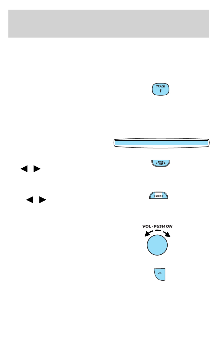
12. Track: Press to locate a specific
MP3 track or directory. TRAC will
appear in the display. Rotate volume
control to advance or reverse through the tracks or directories. The MP3
icon will flash in the display while the MACH威 track function is enabled.
13. Memory presets: To set a station: Select frequency band AM/FM;
tune to a station, press and hold a preset button until sound returns.
14. CD door: Insert a CD with the
label side up.
15. Tune/Directory: Press TUNE
DIR
frequency down/up or change the
MP3 directories.
16. Seek: Press and release
SEEK
strong station selection or CD and
MP3 tracks.
17. Power/volume: Press to turn
ON/OFF; turn to increase or
decrease volume levels.
/ to change the radio
/ for previous/next
18. CD: Press CD to play a CD or
MP3 disc. When the MP3 disc is
loaded, CD and LOAD will appear
on the display. The display will
briefly show the total number of tracks on the disc as TXXX
(XXX=number of tracks).
26
Page 27
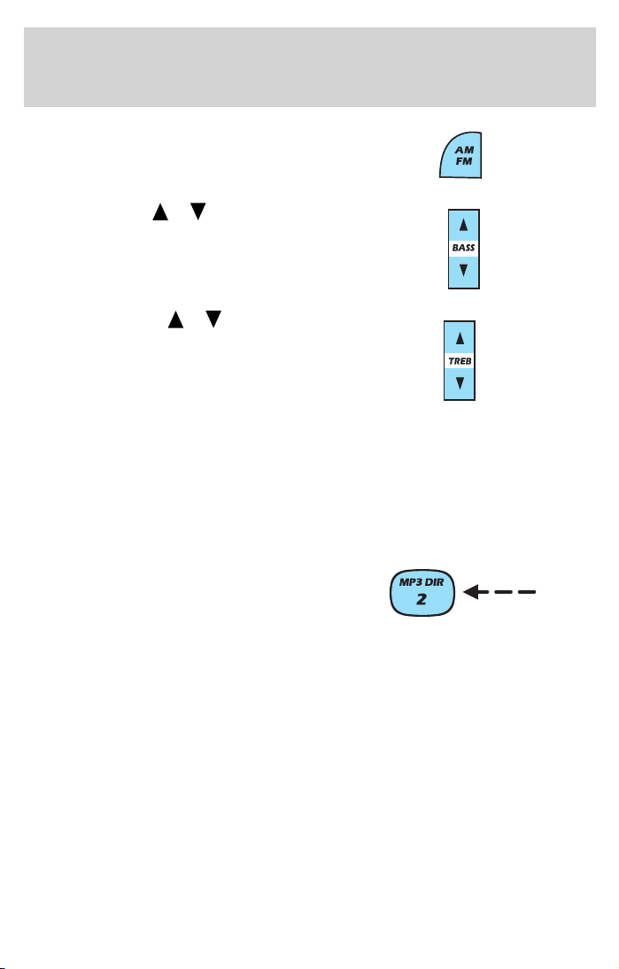
19. AM/FM: Press to select a
frequency band in radio mode.
Entertainment Systems
20. Bass: Press
decrease/increase the bass output.
21. Treble: Press
decrease/increase the treble output.
MP3 FUNCTIONS
Your audio system is equipped with MP3 capability which allows you to
listen to songs in MP3 flat file mode and MP3 directory mode.
To engage MP3 flat file mode, insert an MP3 disc. If an MP3 disc is
already present in the player, press the CD control. The MP3 icon will
display while the player is in MP3 mode.
While in MP3 flat file mode, press
the MP3 DIR control to enter into
MP3 directory mode. The MP3 icon
and the DIR icon will display while
the player is in directory mode.
Your MACH威 MP3 player is also equipped with an anti-shock buffer for
MP3 discs.
MP3 FILE DIRECTORY STRUCTURE
The MACH威 MP3 music system recognizes MP3 disc file and directory
(folder) structure as follows:
• There are two different modes for MP3 disc playback: MP3 flat file
mode (default) and MP3 directory mode.
• MP3 flat file mode ignores any directory structure present on the MP3
disc. The player sequentially numbers each MP3 track on the disc
(denoted by the .mp3 file extension) from T001 to T255.
/ to
/ to
27
Page 28
Entertainment Systems
• MP3 directory mode represents a directory structure consisting of one
level of directories (folders). The CD player sequentially numbers all
MP3 tracks on the disc (denoted by .mp3 extension) and all
directories containing MP3 files, from 01–01 to 99–99. The first two
digits denote the directory number and the last two digits denote the
track number within that directory.
• Creating discs with only one level of subdirectories will help with
navigation through the disc files.
ERROR MESSAGES
You may experience an error message for the following situations:
• NO DISC when the CD control is pressed and there is not a CD
present.
• DISC ERR when there is a damaged or unreadable disc. Such as, data
discs containing no .mp3 files, or for data discs containing more than
255 files or directories.
• CD ERR for any other disc malfunction.
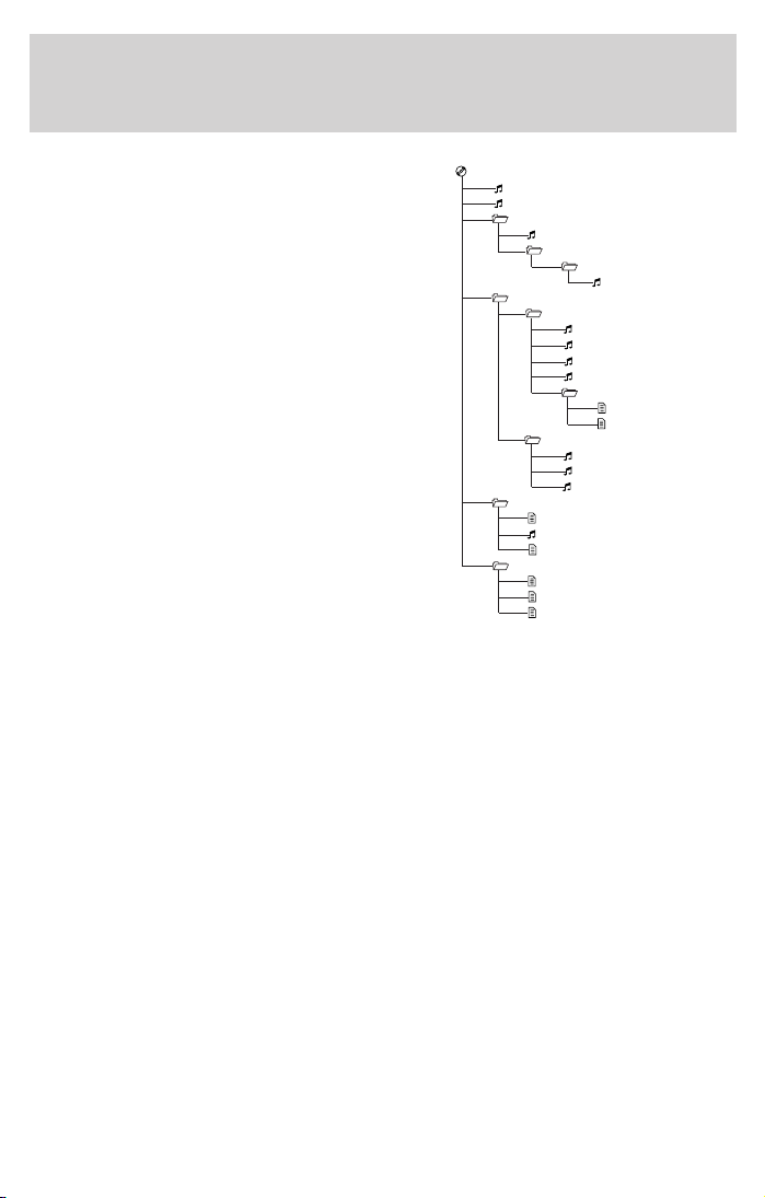
SAMPLE HIERARCHIES
If you are burning your own MP3
discs, it is important to understand
how the MACH威 MP3 music system
will read the hierarchies you create.
This is an example of creating a
directory structure that is one level
deep with various types of music.
While various files are present, (files
with extensions other than mp3),
only files with the .mp3 extension
will be played. Other files will be
ignored by the system. This enables
you to use the same MP3 disc for a
variety of tasks on your work
computer, home computer and your
MACH威 MP3 music system.
28
Page 29
Entertainment Systems
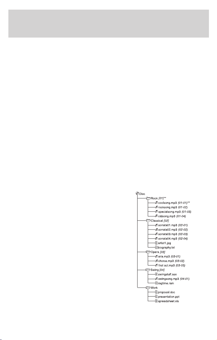
This hierarchy is an example of a
more complex directory structure.
While you are capable of setting up
many directory levels when burning
a CD, the MACH威 MP3 music
system will display the structure as
if it were only one level deep.
Therefore, the system will condense
the complex hierarchy into a
structure similar to the
one-level-deep example above. This
will not harm the MP3 disc and will
not change the hierarchy that is
actually written on the disc. Only
mp3 files will be played, files with
other extensions will be skipped.
Disc
[01]**
coolsong.mp3
rocksong.mp3
Rock
Classical
Swing
Work
(01-01) {T001}
(01-02) {T002}
[02]
specialsong.mp3
Classics
Old Group
Piano
[04]
sonata01.mp3
sonata02.mp3
sonata03.mp3
sonata04.mp3
Album Info
Opera
[05]
aria.mp3
chorus.mp3
first act.mp3
[06]
swingstuff.asx
swingsong.mp3
ragtime.ram
proposal.doc
presentation.ppt
spreadsheet.xls
(02-01) {T003}
[03]
oldsong.mp3
(04-01) {T005}
(04-02) {T006}
(04-03) {T007}
(04-04) {T008}
artist1.jpg
biography.txt
(05-01) {T009}
(05-02) {T010}
(05-03) {T011}
(06-01) {T012}
(03-01) {T004}
In this example, (xx) = directory, (xx-xx) = directory -track, and (Txxx)
= flat file track.
29
Page 30
Entertainment Systems
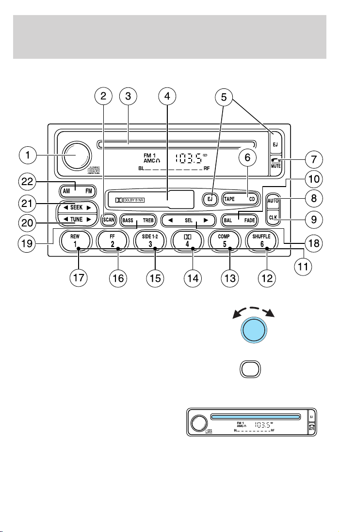
PREMIUM AM/FM STEREO/CASSETTE/SINGLE CD
1. Power/volume: Press to turn
ON/OFF; turn to increase/decrease
volume.
2. Scan: Press to hear a brief
sampling of all listenable stations,
tape selections or CD tracks. Press
again to stop.
3. CD Door: Insert a CD with the
label side up.
CD unit are designed to play
commercially pressed 12 cm
(4.75 in) audio compact discs only. Due to technical
incompatibility, certain recordable and re-recordable compact
discs may not function correctly when used in Ford CD players.
Irregular shaped CDs, CDs with a scratch protection film
attached, and CDs with homemade paper (adhesive) labels should
30
SCAN
Page 31

Entertainment Systems
not be inserted into the CD player. The label may peel and cause
the CD to become jammed. It is recommended that homemade
CDs be identified with permanent felt tip marker rather than
adhesive labels. Ball point pens may damage CDs. Please contact
your dealer for further information.
4. Cassette door: Insert the
cassette with the opening to the
right.
5. Eject: Press to eject the
cassette/CD. The radio will resume
playing.
6. Tape: Press to start tape play.
Press to stop tape during
rewind/fast forward.
CD: Press to start CD play. With the
dual media audio, press CD to
toggle between single CD and CD
changer play (if equipped).
7. Mute: Press to MUTE playing
media; press again return to playing
media.
8. Auto: Press to set first six
strongest stations (if available) into
AM, FM1 or FM2 memory buttons;
press again to return to normal
stations.
9. Clock: Press and hold to set the
clock. Press the
decrease hours or SEEK to
increase hours. Press the
SEEK to
TUNE
31
Page 32

Entertainment Systems
to decrease minutes or TUNE to increase minutes. If your vehicle
has a stand alone clock this control will not function.
10. Balance: Press BAL; then press
SEL
left/right speakers.
Fade: Press FADE; then press
SEL
rear/front speakers.
11. Memory preset buttons: To
set a station: Select frequency band
AM/FM, tune to a station, press and
hold a preset button until sound returns.
12. Shuffle (CD): Press to play
tracks in random order.
13. Compression (CD): Press to
bring soft and loud passages
together for a more consistent
listening level.
14.
Works in tape mode only. Reduces
tape noise and hiss; press to
activate/deactivate.
The Dolby威 noise reduction system is manufactured under license from
Dolby Laboratories Licensing Corporation. Dolby威 and the double-D
symbol are registered trademarks of Dolby Laboratories Licensing
Corporation.
15. Side 1–2: Works in tape mode
only. Press to play reverse side of
the tape.
/ to shift sound to the
/ to shift sound to the
Dolby威 noise reduction:
32
Page 33

Entertainment Systems
16. Fast Forward (FF): Press for
a slow advance, press and hold for a
fast advance.
17. Rewind (REW): Press for a
slow rewind, press and hold for a
fast rewind.
18. Select (SEL): Use with Bass,
Treble, Balance and Fade controls.
19. Bass: Press BASS; then press
SEL
/ to decrease/increase
the bass output.
Treble: Press TREB; then press
SEL
/ to decrease/increase
the treble output.
20. Tune: Works in radio mode only.
Press TUNE
/ to change
frequency down/up.
FF
2
SEEK
TUNE
REW
1
SEL
21. Seek: Press and release
SEEK
/ for previous/next
strong station, selection or track.
22. AM/FM: Press to select
AM/FM1/FM2 frequency band.
SEEK
TUNE
33
Page 34

Entertainment Systems
TREMOR AUDIO SYSTEM
1. MUTE: Press to mute the playing
media. Press again to return to the
playing media.
2. TAPE: Insert the cassette with
the opening to the right. If a tape is
already inserted into the system,
press TAPE to being tape play.
3. CD: Insert a CD label side up. If a
CD is already inserted, press CD to
begin CD play.
34
TAPE
CD
Page 35

Entertainment Systems
4. TUNE: Works in radio mode.
Press to move down
or up
TUNE
the frequency band.
5. SEEK: Turn to listen to the
previous (left) or next (right) radio
station, cassette selection, or CD
track.
SCAN: Press to hear a short
sampling of all listenable radio
stations, cassette selections or CD tracks. Press again to stop and remain
on a desired selection.
6. EJ (Eject): Press to eject a tape.
7. BAL (Balance): Press BAL, then
press SEL( Select) control to adjust
the sound between the left
right
speakers.
or
BAL FADE
FADE: Press FADE, and then press SEL (Select) to adjust the sound
between the front
8. COMP (Compression): Press to
bring soft and loud passages
and rear speakers.
COMP
5
SHUF
6
together for a more consistent
listening level.
SHUF (Shuffle): Works in CD mode only. Press to randomly play all
tracks on the current disc. Press again to disengage random play.
(Dolby威 noise reduction):
9.
Works in tape mode only. Reduces
SIDE 1-2
3
4
tape noise and hiss; press to
activate/deactivate.
Side 1–2: Works in tape mode only. Press to change the playing side of
the tape.
10. SEL (Select): Allows you to
adjust various settings such as bass
SEL
levels, RDS information, the time,
etc.
35
Page 36

Entertainment Systems
11. REW (rewind)/FF (fast
forward): Press to play previous or
REW
FF
2
1
the next cassette selections or CD
tracks.
12. BASS: Press BASS and then
press SEL to decrease
increase
the bass levels.
or
TREB (treble): Press TREB and then press SEL to decrease
BASS TREB
or
increase the treble levels.
13. ON/Off/VOL (Volume): Press
to turn the system ON. Turn to
adjust the volume levels. Press again
VOL
PUSH
ON
to turn the system off.
14. AUTO: Press to set first six
strong stations into AM, FM1 or
AUTO RDS
CLK
FM2 memory controls; press again
to return to normal stations.
RDS: Press to engage Radio Data System and select:
• TRAFFIC — Interrupts playing media to play a traffic report. To
activate, press SCAN or SEEK when TRAFFIC ON is displayed.
• FIND program type — Press SEL to choose the desired program type:
Classic, Country, Info., Jazz/R&B, Religious, Rock, Soft or Top 40.
• SHOW — Displays station name, station type and/or radio text. Press
RDS until SHOW is displayed.
CLK (Clock): Press RDS until SET HOURS is displayed. Press SEL to
decrease
or increase the hours.
Press RDS again until SET MIN is displayed. Press SEL to decrease
or increase the minutes. If your vehicle has a stand alone clock this
control will not function.
36
Page 37

Entertainment Systems
15. AM/FM: Press to select AM or
FM frequency bands. Press to end
tape or CD play and begin radio
AM
FM
play.
16. EJ (Eject): Press to eject a CD.
RADIO FREQUENCIES
AM and FM frequencies are established by the Federal Communications
Commission (FCC) and the Canadian Radio and Telecommunications
Commission (CRTC). Those frequencies are:
AM - 530, 540–1700, 1710 kHz
FM- 87.7, 87.9–107.7, 107.9 MHz
RADIO RECEPTION FACTORS
There are three factors that can affect radio reception:
• Distance/strength: The further you travel from an FM station, the
weaker the signal and the weaker the reception.
• Terrain: Hills, mountains, tall buildings, power lines, electric fences,
traffic lights and thunderstorms can interfere with your reception.
• Station overload: When you pass a broadcast tower, a stronger signal
may overtake a weaker one and play while the weak station frequency
is displayed.
CASSETTE/PLAYER CARE
Do:
• Use only cassettes that are 90 minutes long or less.
• Tighten very loose tapes by inserting a finger or pencil into the hole
and turning the hub.
• Remove loose labels before inserting tapes.
• Allow tapes which have been subjected to extreme heat, humidity or
cold to reach a moderate temperature before playing.
• Clean the cassette player head with a cassette cleaning cartridge after
10–12 hours of play to maintain good sound/operation.
37
Page 38

Entertainment Systems
Don’t:
• Expose tapes to direct sunlight, extreme humidity, heat or cold.
• Leave tapes in the cassette player for a long time when not being
played.
CD/CD PLAYER CARE
Do:
• Handle discs by their edges only. Never touch the playing surface.
• Inspect discs before playing. Clean only with an approved CD cleaner
and wipe from the center out.
Don’t:
• Expose discs to direct sunlight or heat sources for extended periods
of time.
• Insert more than one disc into each slot of the CD changer magazine.
• Clean using a circular motion.
CD units are designed to play commercially pressed 12 cm (4.75
in) audio compact discs only. Due to technical incompatibility,
certain recordable and re-recordable compact discs may not
function correctly when used in Ford CD players. Irregular
shaped CDs, CDs with a scratch protection film attached, and CDs
with homemade paper (adhesive) labels should not be inserted
into the CD player. The label may peel and cause the CD to
become jammed. It is recommended that homemade CDs be
identified with permanent felt tip marker rather than adhesive
labels. Ball point pens may damage CDs. Please contact your
dealer for further information.
AUDIO SYSTEM WARRANTY AND SERVICE
Refer to the Warranty Guide for audio system warranty information. If
service is necessary, see your dealer or qualified technician.
38
Page 39
Climate Controls
HEATER ONLY SYSTEM
(IF EQUIPPED)
1. Fan speed adjustment: Controls
the volume of air circulated in the
vehicle.
2. Temperature selection:
Controls the temperature of the
airflow in the vehicle.
3. Air flow selections: Controls the direction of the airflow in the
vehicle. See the following for a brief description on each control.
: Distributes outside air through the instrument panel vents.
OFF: Outside air is shut out and the fan will not operate.
: Distributes outside air through the instrument panel vents and the
floor vents.
: Distributes outside air through the floor vents.
: Distributes outside air through the windshield defroster vents and
floor vents.
: Distributes outside air through the windshield defroster vents.
OPERATING TIPS
• To reduce fog build up on the windshield during humid weather, place
the air flow selector in the
• To reduce humidity build up inside the vehicle during cold or warm
weather, do not drive with the air flow selector in the OFF position.
• Under normal weather conditions, do not leave the air flow selector in
OFF when the vehicle is parked. This allows the vehicle to “breathe”
using the outside air inlet vents.
• Do not put objects under the front seats that will interfere with the air
flow to the back seats.
• Remove any snow, ice or leaves from the air intake area at the base of
the windshield.
position.
39
Page 40

Climate Controls
To aid in side window defogging/demisting in cold weather:
1. Select
2. Set the temperature control to full heat
3. Set the fan speed to HI
4. Direct the outer instrument panel vents towards the side windows
To increase airflow to the outer instrument panel vents, close the vents
located in the middle of the instrument panel.
Do not place objects on top of the instrument panel as these
objects may become projectiles in a collision or sudden stop.
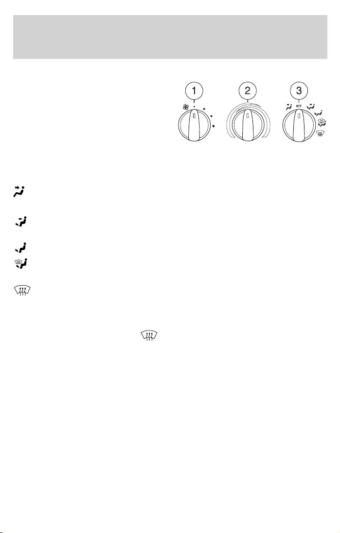
MANUAL HEATING AND AIR
CONDITIONING SYSTEM
1. Fan speed adjustment: Controls
the volume of air circulated in the
vehicle.
2. Temperature selection:
Controls the temperature of the
airflow in the vehicle.
3. Air flow selections: Controls the direction of the airflow in the
vehicle. See the following for a brief description on each control.
MAX A/C: Uses recirculated air to cool the vehicle. Air flows from the
instrument panel vents only.
A/C: Uses outside air to cool the vehicle. Air flows from the instrument
panel vents only.
: Distributes outside air through the instrument panel vents.
OFF: Outside air is shut out and the fan will not operate.
: Distributes outside air through the instrument panel vents and the
floor vents.
: Distributes outside air through the floor vents.
: Distributes outside air through the windshield defroster vents and
floor vents.
: Distributes outside air through the windshield defroster vents.
40
Page 41

Climate Controls
OPERATING TIPS
• To reduce fog build up on the windshield during humid weather, place
the air flow selector in the
• To reduce humidity build up inside the vehicle: do not drive with the
air flow selector in the OFF or MAX A/C position.
• Under normal weather conditions, do not leave the air flow selector in
MAX A/C or OFF when the vehicle is parked. This allows the vehicle
to “breathe” using the outside air inlet vents.
• Do not put objects under the front seats that will interfere with the
airflow to the back seats.
• Remove any snow, ice or leaves from the air intake area at the base of
the windshield.
To aid in side window defogging/demisting in cold weather:
1. Select
2. Select A/C
3. Modulate the temperature control to maintain comfort.
4. Set the fan speed to HI
5. Direct the outer instrument panel vents towards the side windows
To increase airflow to the outer instrument panel vents, close the vents
located in the middle of the instrument panel.
position.
Do not place objects on top of the instrument panel as these
objects may become projectiles in a collision or sudden stop.
41
Page 42

Lights
HEADLAMP CONTROL
Turns the lamps off.
Turns on the parking
lamps, instrument panel lamps,
license plate lamps and tail lamps.
Turns the headlamps on.
Foglamp control (if equipped)
The foglamps can be turned on
when the headlamp control is in
either of the following positions:
• Parking lamps
• Low beams
Press the foglamp control to activate the foglamps.
Press the foglamp control again to deactivate the foglamps.
When the highbeams are activated, the foglamps will not operate.
Daytime running lamps (DRL) (if equipped)
Turns the headlamps on with a reduced output.
To activate:
• the ignition must be in the ON position and
• the headlamp control is in the OFF, parking lamp or autolamp
position.
OFF
Always remember to turn on your headlamps at dusk or during
inclement weather. The Daytime Running Lamp (DRL) system
does not activate with your tail lamps and generally may not provide
adequate lighting during these conditions. Failure to activate your
headlamps under these conditions may result in a collision.
42
Page 43

Lights
High beams
Push the lever toward the
instrument panel to activate. Pull
the lever towards you to deactivate.
Flash to pass
Pull toward you slightly to activate
and release to deactivate.
PANEL DIMMER CONTROL
Use to adjust the brightness of the
instrument panel and all applicable
switches in the vehicle during
headlamp and parklamp operation.
Move the control up or down to
adjust the intensity of the panel
lighting.
Move the control to the full upright
position, past detent, to turn on the interior lamps.
AIMING THE HEADLAMPS
The headlamps on your vehicle are properly aimed before leaving the
assembly plant. If your vehicle is involved in an accident or if you have
problems fixing the alignment of your headlamps, have them checked by
a qualified service technician.
Headlamp aim adjustment
The headlamps on your vehicle can only be vertically adjusted. Your
vehicle does not require horizontal aim adjustments.
DIM
43
Page 44

Lights
To adjust the headlamps:
1. Park your vehicle on a level
surface about 7.6 meters (25 feet)
away from a vertical plain surface
(3). Check your headlamp alignment
at night or in a dark area so that
you can see the headlamp beam
pattern.
• (1) Eight feet
• (2) Center height of lamp to
ground
• (3) Twenty-five feet
• (4) Horizontal reference line
2. The center of the headlamp has a 3.0 mm circle on the lens. Measure
the height from the center of your headlamp to the ground (2) and mark
a 2.4 meter (8 foot) long horizontal line on the plain surface (1) at this
height (masking tape works well).
3. Turn on the low beam headlamps.
The brightest part of the light
should be below the horizontal line
(4). If it is above the line the
headlamp will need to be adjusted.
4. Open the hood.
5. Locate the vertical adjuster for
each headlamp. Adjust the aim by
turning the adjuster control either
clockwise (to adjust down) or
counterclockwise (to adjust up).
Note: Usea4mmsocket or box
wrench to turn the vertical adjuster
control.
6. Horizontal aiming is not required
for this vehicle and is
non-adjustable.
44
Page 45

TURN SIGNAL CONTROL
• Push down to activate the left
turn signal.
• Push up to activate the right turn
signal.
INTERIOR LAMPS
DOME LAMP
The courtesy lamp lights when:
• any door is opened.
• the instrument panel dimmer
switch is held up until the
courtesy lamps come on.
• the remote entry controls are
pressed and the ignition is OFF.
Lights
BULBS
Replacing exterior bulbs
Check the operation of all the bulbs frequently.
Using the right bulbs
Replacement bulbs are specified in the chart below. Headlamp bulbs
must be marked with an authorized “D.O.T.” for North America and an
“E” for Europe to assure lamp performance, light brightness and pattern
and safe visibility. The correct bulbs will not damage the lamp assembly
or void the lamp assembly warranty and will provide quality bulb burn
time.
45
Page 46

Lights
Function Number of bulbs Trade number
Park/turn/side marker
lamps (front)
Headlamps 2 9007
Foglamps (if
equipped)
Hi-mount brakelamp 1 922
Cargo lamps 2 906
Rear stop/turn/tail
lamps
Rear license plate
lamps
Backup lamp 2 3156K
Dome lamp 1 912
Glove compartment 1 194
Map/dome-SuperCab
(if equipped)
Map/dome-Regular
Cab (if equipped)
All replacement bulbs are clear in color except where noted.
To replace all instrument panel lights - see your dealer.
2 3457AK
2 194
2
2
2
2
1 904
1 904
9145
3157K
194
904
Replacing the interior bulbs
Check the operation of all bulbs frequently.
46
Page 47

Replacing headlamp bulbs
To remove the headlamp bulb:
1. Turn the headlamp switch is in
the OFF position, then open the
hood.
2. Remove two screws and cover
(if equipped).
3. At the back of the headlamp, pry
up the two retainer pins to release
the headlamp assembly from the
vehicle and pull headlamp forward.
4. Disconnect the electrical
connector from the bulb by pulling
rearward.
5. Remove the bulb retaining ring by
rotating it counterclockwise and
slide the ring off the plastic base.
Lights
6. Remove the old bulb by pulling it
straight out of the lamp.
Handle a halogen headlamp bulb carefully and keep out of
children’s reach. Grasp the bulb only by its plastic base and do
not touch the glass. The oil from your hand could cause the bulb to
break the next time the headlamps are operated.
Install the new bulb(s) in reverse order.
47
Page 48

Lights
Replacing front side marker bulbs
1. Turn the headlamp switch to the
OFF position and then open the
hood.
2. Remove two screws and cover
(if equipped).
3. At the back of the headlamp, pry
up the two retainer pins to release
the headlamp assembly from the
vehicle and pull headlamp forward.
4. Remove screw(s) from lamp
assembly and disengage lamp
assembly (it has a snap fit).
5. Rotate bulb socket
counterclockwise and remove from
lamp assembly.
6. Carefully pull bulb straight out of
socket and push in the new bulb.
7. Install the bulb socket in lamp
assembly by turning clockwise.
Install the new lamp in reverse order.
48
Page 49

Replacing tail lamp/backup lamp bulbs
1. Open the tailgate to expose the
lamp assemblies.
2. Remove the four screws and the
lamp assembly from vehicle.
3. Rotate bulb socket
counterclockwise turn and remove
from lamp assembly.
4. Carefully pull the bulb straight
out of the socket
Lights
Install the new bulb(s) in reverse order.
49
Page 50

Lights
Replacing foglamp bulbs (if equipped)
1. Remove the bulb socket from the
foglamp by turning
counterclockwise.
2. Disconnect the electrical
connector.
Install the new bulb in reverse order.
Replacing high-mount brakelamp and cargo lamp bulbs
1. Remove the two screws and lamp
assembly from vehicle.
2. Remove the bulb socket from
lamp assembly by rotating it
counterclockwise.
3. Carefully pull bulb straight out of
socket.
Install the new bulb(s) in reverse order.
Replacing license plate lamp bulbs
1. Reach behind the rear bumper to
locate the bulb socket.
2. Twist the socket counterclockwise
and remove.
3. Carefully pull the bulb straight
out of the socket.
Install the new bulb(s) in reverse order.
50
Page 51

Driver Controls
MULTI-FUNCTION LEVER
Windshield wiper: Rotate the end
of the control away from you to
increase the speed of the wipers
(from desired interval to low or high
speed position); rotate towards you
to decrease the speed of the wipers.
Windshield washer: Push the end
of the stalk:
• briefly: causes a single swipe of
the wipers without washer fluid.
• a quick push and hold: the wipers
will swipe three times with
washer fluid.
• a long push and hold: the wipers and washer fluid will be activated for
up to ten seconds.
Changing the wiper blades
1. Pull the wiper arm away from the
vehicle. Turn the blade at an angle
from the wiper arm. Push the lock
pin manually to release the blade
and pull the wiper blade down
toward the windshield to remove it
from the arm.
2. Attach the new wiper to the
wiper arm and press it into place
until a click is heard.
3. Replace wiper blades every 6 months for optimum performance.
51
Page 52

Driver Controls
TILT STEERING WHEEL (IF EQUIPPED)
To adjust the steering wheel:
1. Pull and hold the steering wheel
release control toward you.
2. Move the steering wheel up or
down until you find the desired
location.
3. Release the steering wheel
release control. This will lock the
steering wheel in position.
Never adjust the steering wheel when the vehicle is moving.
AUXILIARY POWER POINT
Power outlets are designed for
accessory plugs only. Do not
hang any type of accessory or
accessory bracket from the plug.
Improper use of the power
outlet can cause damage not
covered by your warranty.
The auxiliary power point is located
on the instrument panel. Do not
plug optional electrical accessories
into the cigarette lighter. Use the
power point.
Do not use the power point for operating the cigarette lighter element.
The Maximum power each power point can supply depends on the fuse
rating. For example: a 20A fuse should supply a maximum of 240 Watts,
a 15A fuse should supply a maximum of 180 Watts and a 10A fuse should
supply a maximum of 120 Watts. Exceeding these limits will result in a
blown fuse. Refer to Passenger Compartment Fuse Panel in the
Roadside Emergencies chapter for fuse ratings in your vehicle.
Always keep the power point caps closed when not being used.
52
Page 53

Driver Controls
POWER WINDOWS (IF EQUIPPED)
When closing the power
windows, you should verify
they are free of obstructions and
ensure that children and/or pets
are not in the proximity of the
window openings.
Press and hold the bottom part of the rocker switch to open the window.
Press and hold the top part of the rocker switch to close the window.
One touch down
Allows the driver’s window to open
fully without holding the control
down. Press completely down on
AUTO and release quickly. Press
again to stop.
POWER SIDE VIEW MIRRORS (IF EQUIPPED)
To adjust your mirrors:
1. Select to adjust the left
mirror or
mirror.
2. Move the control in the direction
you wish to tilt the mirror.
3. Return to the center position to
lock mirrors in place.
to adjust the right
53
Page 54

Driver Controls
SPEED CONTROL (IF EQUIPPED)
With speed control set, you can
maintain a speed of 48 km/h (30
mph) or more without keeping your
foot on the accelerator pedal. Speed
control does not work at speeds
below 48 km/h (30 mph).
Do not use the speed
control in heavy traffic or
on roads that are winding, slippery
or unpaved.
Setting speed control
The controls for using your speed
control are located on the steering
wheel for your convenience.
1. Press the ON control and release
it.
2. Accelerate to the desired speed.
3. Press the SET ACCEL control
and release it.
4. Take your foot off the accelerator
pedal.
SPEED
5. The indicator light
CONT
on the
instrument cluster will turn on.
Note:
• Vehicle speed may vary momentarily when driving up and down a
steep hill.
• If the vehicle speed increases above the set speed on a downhill, you
may want to apply the brakes to reduce the speed.
54
Page 55
Driver Controls
• If the vehicle speed decreases more than 16 km/h (10 mph) below
your set speed on an uphill, your speed control will disengage.
• If the vehicle speed decreases to 40 km/h (25 mph) or less, your
speed control will disengage
Disengaging speed control
To disengage the speed control:
• Depress the brake pedal or
• Depress the clutch pedal (if equipped).
Disengaging the speed control will not erase previous set speed.
Note: When you use the clutch pedal to disengage the speed control,
the engine speed may briefly increase, this is normal.
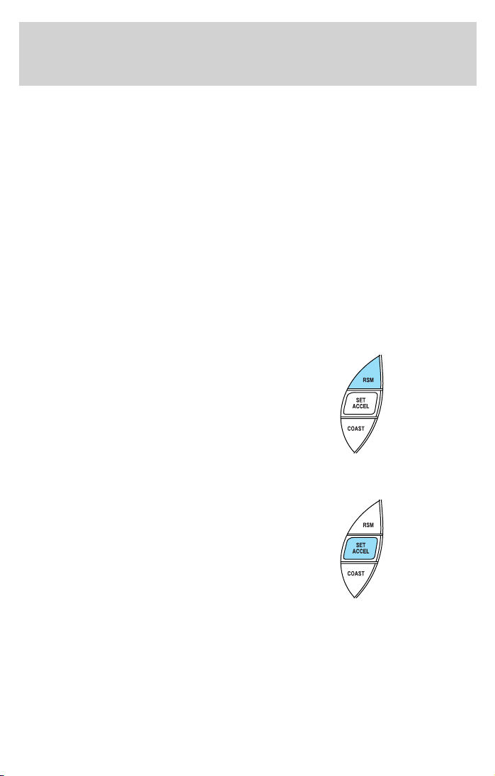
Resuming a set speed
Press the RSM (resume) control and
release it. This will automatically
return the vehicle to the previously
set speed. The RSM control will not
work if the vehicle speed is not
faster than 48 km/h (30 mph).
Increasing speed while using speed control
There are three ways to set a higher
speed:
• Press and hold the SET ACCEL
control until you get to the
desired speed, then release the
control.
• Press and release the SET
ACCEL control to operate the
Tap-Up function. Each tap will increase the set speed by 1.6 km/h
(1 mph).
• Use the accelerator pedal to get to the desired speed. When the
vehicle reaches that speed press and release the SET ACCEL control.
55
Page 56

Driver Controls
Reducing speed while using speed control
There are three ways to reduce a
set speed:
• Press and hold the COAST
control until you get to the
desired speed, then release the
control.
• Press and release the COAST
control to operate the Tap-Down
function. Each tap will decrease the set speed by 1.6 km/h (1 mph).
• Depress the brake pedal or the
clutch pedal (if equipped) until
the desired vehicle speed is
reached, press the SET ACCEL
control.
Turning off speed control
There are two ways to turn off the
speed control:
• Press the speed control OFF
control.
• Turn OFF the ignition.
Note: When you turn off the speed
control or the ignition, your speed
control set speed memory is erased.
56
Page 57

Driver Controls
CENTER CONSOLE (IF EQUIPPED)
Your vehicle may be equipped with a
variety of console features. These
include:
• Utility compartment with
cassette/compact disc storage
• Cupholders
• Coin holder slots
• Flip up armrest
Use only soft cups in the cupholder. Hard objects can injure you
in a collision.
Cell phone use
The use of Mobile Communications Equipment has become increasingly
important in the conduct of business and personal affairs. However,
drivers must not compromise their own or others’ safety when using
such equipment. Mobile Communications can enhance personal safety
and security when appropriately used, particularly in emergency
situations. Safety must be paramount when using mobile communications
equipment to avoid negating these benefits.
Mobile Communication Equipment includes, but is not limited to cellular
phones, pagers, portable email devices, in vehicle communications
systems, telematics devices and portable two-way radios.
A driver’s first responsibility is the safe operation of the vehicle.
The most important thing you can do to prevent a crash is to
avoid distractions and pay attention to the road. Wait until it is safe to
operate Mobile Communications Equipment.
CARGO AREA FEATURES
Cargo area shade (if equipped)
Your vehicle may be equipped with notches in the side trim panels that
are used for a cargo area shade. See your dealer for more information.
57
Page 58

Driver Controls
BEDRAILS (IF EQUIPPED)
• This bedrail is for appearance use only.
• To help prevent injury, do not use bedrail to retain cargo.
• Retain cargo with the pickup tie down hooks.
BED EXTENDER (IF EQUIPPED)
Your vehicle may be equipped with a bed extender designed to extend
the pickup box for longer loads.
To extend the bed extender:
1. Lower tailgate.
2. Pull the round knobs on each side
of the extender to release it from
the pickup box.
3. Pivot extender on to the tailgate.
4. Evenly push down on the
extender and push the round knobs
in on each side locking it in place.
Green markings on the shaft
indicate the locked position. The
locking clip screws below the middle
bar can be tightened
counterclockwise for extra security.
Note: If the red marking on the
shaft is visible, the bed extender
is not locked or properly secured.
To stow the bed extender, follow steps one through four in reverse order.
The bed extender may be used to secure a load of up to 46 kg (100 lbs.)
on the tailgate.
The bed extender should always be kept in the stowed position
with the tailgate closed when not in use.
When driving the vehicle off road, the bed extender should be
removed and the tailgate closed.
58
Page 59

Driver Controls
To remove the bed extender:
1. Extend the bed extender.
2. Pull the round knobs on each side
of the extender to unlock it.
Make sure the locking clip screws
are loose before removing the
extender.
3. Press the locking clips below the
middle bar on each side and lift the
extender out of the bed.
To install the bed extender, follow the removal procedure in reverse
order.
TONNEAU COVER (IF EQUIPPED)
The tonneau cover has been designed to maximize fuel economy and
should be fully installed whenever possible.
The rear panel can be folded in half and secured behind the cab, or the
whole cover can be removed completely from the vehicle.
To avoid damage to the cover, do not operate the vehicle unless
the cover is fully installed, or securely stowed.
To open the front panel:
• Open the lock cover and unlock
the front or rear panel.
• Lift the panel to access items in
the pickup box.
The panels will automatically
lock when lowered onto the
pickup box.
• To close, lower the front or rear
panel down on the pickup box.
59
Page 60

Driver Controls
Do not drive with front panel
unlocked or folded on top of the
rear panel.
To stow the rear panel:
• Before driving with the tonneau
cover open, stow the rear panel.
• Disconnect the hydraulic
cylinders from the ball stud on
the pickup box and secure them
in the clips on the tonneau cover.
• Lift the rear panel up, lay it on
top of the front panel and secure
it to the hooks on the front panel
with the tiedown cords.
Failure to secure the rear panel
could damage the tonneau cover
or vehicle.
60
Page 61

The cargo divider is designed to
divide your pickup box in half or
rotate 90° to allow you full use of
the pickup box.
To rotate the cargo divider 90°:
• Open front panel.
• Pull the lower release lever out
on each side of the cargo divider
to unlatch from the pickup box.
• Rotate the divider 90° parallel
with the tonneau cover and
secure it to the pickup box with
the lower release levers.
To rotate the cargo divider back,
follow the procedure in reverse order.
To remove the cargo divider:
• Open the front panel.
• Pull two release levers out on
each side of the cargo divider
from the pickup box and remove.
For installation of the cargo divider,
follow the removal procedure in
reverse order.
Driver Controls
61
Page 62

Driver Controls
To remove the tonneau cover:
The tonneau cover needs to be
supported during removal. This is a
two person operation.
• Remove the cargo divider, refer
to To remove the cargo divider
on the previous page.
• Disconnect the hydraulic
cylinders from the pickup box
and secure them in the clips on
the tonneau cover. Close the front panel.
• Open and support the front panel.
• Stow the rear panel on top of the front panel, refer to To stow the
rear panel shown previously.
• Pull two release levers on the underside of the tonneau cover from the
pickup box and remove the tonneau cover.
For installation of the tonneau cover, reverse the removal procedure.
62
Page 63

Locks and Security
KEYS
The key operates all locks on your vehicle. In case of loss, replacement
keys are available from your dealer.
You should always carry a second key with you in a safe place in case
you require it in an emergency.
Refer to SecuriLock娂 Passive Anti-Theft System for more information.
POWER DOOR LOCKS (IF EQUIPPED)
If the door does not unlock when
the top of the control is pressed,
see Interior power door unlock
disable feature in the Remote entry
section in this chapter.
Press the top of the control to
unlock all doors and the bottom to
lock all doors.
INTERIOR TONNEAU COVER RELEASE (IF EQUIPPED)
Your vehicle is equipped with a mechanical interior tonneau cover
release handle that provides a means of escape for children and adults in
the event they become locked inside the pickup box.
Adults are advised to familiarize themselves with the operation and
location of the release handle.
UNLOCK
LOCK
63
Page 64

Locks and Security
To open the tonneau cover from the
inside, pull the “T” shaped handle
and push up on the tonneau cover
panel. The handle is composed of a
material that will glow for hours in
darkness following brief exposure to
ambient light.
The “T” shaped handle is located on
the tonneau cover panel.
Keep vehicle doors and tonneau cover locked and keep keys and
remote transmitters out of a child’s reach. Unsupervised children
could lock themselves in the box and risk injury. Children should be
taught not to play in vehicles.
On hot days, the temperature in the pickup box can rise very
quickly. Exposure of people or animals to these high
temperatures for even a short time can cause death or serious
heat-related injuries, including brain damage. Small children are
particularly at risk.
REMOTE ENTRY SYSTEM (IF EQUIPPED)
This device complies with part 15 of the FCC rules and with RS-210 of
Industry Canada. Operation is subject to the following two conditions:
(1) This device may not cause harmful interference, and (2) This device
must accept any interference received, including interference that may
cause undesired operation.
Changes or modifications not expressly approved by the party
responsible for compliance could void the user’s authority to
operate the equipment.
64
Page 65

Locks and Security
Your vehicle is equipped with a remote entry system which allows you to:
• unlock the vehicle doors without
a key.
• lock all the vehicle doors without
a key.
• activate the personal alarm.
If there is any potential remote keyless entry problem with your vehicle,
ensure ALL remote entry transmitters are taken to the dealership, to
aid in troubleshooting.
Unlocking the doors
1. Press and release to unlock the driver’s door. Note: The interior
lamps will illuminate.
2. Press
doors.
Locking the doors
1. Press and release to lock all the doors.
and release again within three seconds to unlock all the
2. Press
doors are closed and locked. Note: the doors will lock again, the horn
will chirp once, and the lamps will flash.
If any of the doors are not properly closed the horn will make two quick
chirps and the lamps will not flash.
and release again within three seconds to confirm that all the
65
Page 66

Locks and Security
Power door unlock disabled
The UNLOCK feature on your power
door locks will not work from inside
the vehicle when:
• the ignition has been turned to the OFF position, and
• 20 seconds elapse after all vehicle doors are closed and locked using
the remote entry transmitter, or the power door unlock control (while
the accompanying door is open).
The UNLOCK feature will work again after:
• a door has become ajar,
• the ignition is turned to the ON position, or
• using the UNLOCK
control on your remote entry transmitter, or
• using the keyless entry keypad to unlock the vehicle.
Deactivating/activating power door lock disable feature
This feature can be activated and deactivated by an authorized dealer.
Sounding a panic alarm
Press
to activate the alarm. The horn will sound for a maximum of
30 seconds and the parklamps will flash for a maximum of 3 minutes.
Press again or turn the ignition to ON to deactivate, or wait for the alarm
to timeout in 3 minutes.
Note: The panic alarm will only operate when the ignition is in the OFF
or ACC position.
UNLOCK
LOCK
Replacing the battery
The remote entry transmitter uses one coin type three-volt lithium
battery CR2032 or equivalent. The typical operating range for your
remote entry transmitter is approximately 10 meters (33 feet). A
decrease in the operating range could be caused by:
• weather conditions,
• nearby radio towers,
66
Page 67

Locks and Security
• structures around the vehicle and
• other vehicles parked next to the vehicle.
To replace the battery:
1. Twist a thin coin between the two
halves of the remote entry
transmitter near the key ring. DO
NOT TAKE THE FRONT PART OF
THE REMOTE ENTRY
TRANSMITTER APART.
2. Remove the old battery.
3. Insert the new battery. Refer to
the diagram inside the remote entry
transmitter for the correct orientation of the battery.
4. Snap the two halves back together.
Note: Replacement of the battery will not cause the remote transmitter
to become deprogrammed from your vehicle. The remote transmitter
should operate normally after battery replacement.
Replacing lost remote entry transmitters
If you would like to have your remote entry transmitter reprogrammed
because you lost one, or would like to buy additional remote entry
transmitters, you can either reprogram them yourself, or take all
remote entry transmitters to your authorized dealer for
reprogramming.
How to reprogram your remote entry transmitters
You must have all remote entry transmitters (maximum of four)
available before beginning this procedure.
To reprogram the remote entry
transmitters:
1. Ensure the vehicle is
electronically unlocked.
2. Put the key in the ignition.
3. Turn the key from the 2 (LOCK)
position to 3 (OFF).
4. Cycle, eight times, rapidly (within
10 seconds) between the 3 (OFF)
position and 4 (ON). Note: The
eighth turn must end in the 4 (ON) position.
3
2
1
4
5
67
Page 68

Locks and Security
5. The doors will lock, then unlock, to confirm that the programming
mode has been activated.
6. Within 20 seconds press any button on the remote entry transmitter.
Note: If more than 20 seconds have passed you will need to start the
procedure over again.
7. The doors will lock, then unlock, to confirm that this remote entry
transmitter has been programmed.
8. Repeat Step 6 to program each additional remote entry transmitter.
9. Turn the ignition to the 3 (OFF) position after you have finished
programming all of the remote entry transmitters. Note: After 20
seconds have passed, you will automatically exit the programming mode.
10. The doors will lock, then unlock, to confirm that the programming
mode has been exited.
Illuminated entry
The interior lamps illuminate when the remote entry system is used to
unlock the door(s) or sound the personal alarm.
The illuminated entry system will turn off the interior lights if:
• the ignition switch is turned to the ON position, or
• the remote transmitter lock control is pressed, or
• after 25 seconds of illumination.
The dome lamp control (if equipped) must not be set to the OFF
position for the illuminated entry system to operate.
The inside lights will not turn off if:
• they have been turned on with the dimmer control, or
• any door is open.
The battery saver will shut off the interior lamps 45 minutes after the
last door is closed, even if the dimmer control is on.
SECURILOCK姟 PASSIVE ANTI-THEFT SYSTEM
SecuriLock娂 passive anti-theft system is an engine immobilization
system. This system is designed to prevent the engine from being started
unless a coded key programmed to your vehicle is used. The use of
the wrong type of coded key may lead to a “no-start” condition.
Your vehicle comes with two coded keys; additional coded keys may be
purchased from your dealer. The dealer can program your spare keys to
68
Page 69

Locks and Security
your vehicle or you can program the keys yourself. Refer to
Programming spare keys for instructions on how to program the coded
key.
Note: The SecuriLock娂 passive anti-theft system is not compatible with
non-Ford aftermarket remote start systems. Use of these systems may
result in vehicle starting problems and a loss of security protection.
Note: Large metallic objects, electronic devices that are used to
purchase gasoline or similar items, or a second coded key on the same
key chain may cause vehicle starting issues. You need to prevent these
objects from touching the coded key while starting the engine. These
objects will not cause damage to the coded key, but may cause a
momentary issue if they are too close to the key when starting the
engine. If a problem occurs, turn the ignition off, remove all objects on
the key chain away from the coded key and restart the engine.
Theft indicator
The theft indicator is located in the instrument cluster.
• When the ignition is in the OFF position, the indicator will flash once
every 2 seconds to indicate the SecuriLock娂 system is functioning as
a theft deterrent.
• When the ignition is in the ON position, the indicator will glow for 3
seconds, then turn off, to indicate normal system functionality.
If a problem occurs with the SecuriLock娂 system, the indicator will flash
rapidly or glow steadily when the ignition is in the ON position. If this
occurs, the vehicle should be taken to an authorized dealer for service.
Automatic arming
The vehicle is armed immediately
after switching the ignition to the 3
(OFF) position.
The
THEFT
every two seconds when the vehicle
is armed.
indicator will flash
3
4
5
2
1
69
Page 70

Locks and Security
Automatic disarming
Switching the ignition to the 4 (ON) position with a coded key disarms
the vehicle.
• The
THEFT
out.
• If the
flashes rapidly, have the system serviced by your dealer.
Replacement keys
If your keys are lost or stolen and you don’t have an extra coded key,
you will need to have your vehicle towed to a dealership. The key codes
need to be erased from your vehicle and new coded keys will need to be
programmed.
Replacing coded keys can be very costly. Store an extra programmed key
away from the vehicle in a safe place to help prevent any
inconveniences. Please visit an authorized dealer to purchase additional
spare or replacement keys.
Programming spare keys
You can program your own coded keys to your vehicle. Please read and
understand the entire procedure before you begin.
Tips:
• A maximum of eight keys can be coded to your vehicle.
• Only use Securilock娂 keys.
• You must have two previously programmed coded keys (keys that
already operate your vehicle’s engine) and the new unprogrammed
key(s) readily accessible.
• If no previously programmed coded keys are available, you must take
your vehicle to your dealer to have the spare key(s) programmed.
indicator will illuminate for three seconds and then go
THEFT
indicator stays on for an extended period of time or
70
Page 71

Locks and Security
1. Insert a previously programmed
coded key into the ignition.
2. Turn the ignition from the 3
(OFF) position to the 4 (ON)
position. Keep the ignition in the 4
(ON) position for at least one
second, but no more than 10
seconds.
3. Turn the ignition to the 3 (OFF)
position, and remove the coded key
from the ignition.
4. Within ten seconds of removing the previously programmed coded key,
insert the other previously programmed coded key into the ignition.
5. Turn the ignition from the 3 (OFF) position to the 4 (ON) position.
Keep the ignition in the 4 (ON) position for at least one second but not
more than 10 seconds.
6. Turn the ignition to the 3 (OFF) position, and remove the second key
from the ignition.
7. Within twenty seconds of removing the previously programmed coded
key, insert the unprogrammed key (new/valet key) into the ignition.
8. Turn the ignition from the 3 (OFF) position to the 4 (ON) position.
Keep the ignition in the 4 (ON) position for at least one second.
9. Your new unprogrammed key is now programmed.
If the key has been successfully programmed it will start the vehicle’s
engine and the theft indicator light will illuminate for three seconds and
then go out. If the key was not successfully programmed, it will not start
your vehicle’s engine and the theft indicator light will flash on and off
rapidly. If failure repeats, bring your vehicle to your dealer to have the
new key(s) programmed.
To program additional new unprogrammed key(s), repeat this procedure
from step 1 for each additional key.
3
2
1
4
5
71
Page 72

Seating and Safety Restraints
SEATING
Notes:
Reclining the seatback can cause an occupant to slide under the
seat’s safety belt, resulting in severe personal injuries in the
event of a collision.
Do not pile cargo higher than the seatbacks to reduce the risk of
injury in a collision or sudden stop.
Adjusting the front manual seat
Never adjust the driver’s seat or seatback when the vehicle is
moving.
Always drive and ride with your seatback upright and the lap
belt snug and low across the hips.
Lift handle to move seat forward or
backward.
Pull lever up to adjust seatback.
72
Page 73

Seating and Safety Restraints
Using the manual lumbar support (if equipped)
Turn the lumbar support control
clockwise to increase firmness.
Turn the lumbar support control
counterclockwise to increase
softness.
Passenger side rear access (if equipped)
Pull up on the recliner handle. The
seat will lean forward and unlock
the track. Slide the seat forward to
access the rear area of the cab.
To return seat to original position, slide the seat bottom back, then push
the seatback up to lock it in place. If the seatback is pushed first, the
seat will lock, and you will have to use the seat adjust handle to move
the seat back to the original position.
REAR SEATS
Center facing jump seat (2 door SuperCab) (if equipped)
To open, pull inboard and down on the seat handle.
To stow the seat, pull seat bottom back to the fully upright position.
Do not install a child seat in a center facing jump seat.
73
Page 74
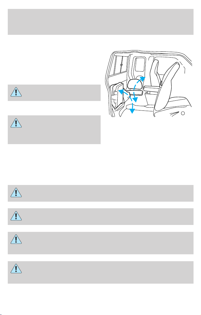
Seating and Safety Restraints
Center facing jump seat (4 door SuperCab) (if equipped)
To open, pull seat assembly down,
then raise seatback.
To stow the seat, fold seat back
down and raise seat assembly to the
fully upright position.
Do not install a child seat in
a center facing jump seat.
Booster seats must be
installed only in seating
positions equipped with a
combination lap/shoulder belt.
SAFETY RESTRAINTS
Safety restraints precautions
Always drive and ride with your seatback upright and the lap
belt snug and low across the hips.
To reduce the risk of injury, make sure children sit where they
can be properly restrained.
Never let a passenger hold a child on his or her lap while the
vehicle is moving. The passenger cannot protect the child from
injury in a collision.
All occupants of the vehicle, including the driver, should always
properly wear their safety belts, even when an air bag (SRS) is
provided.
74
Page 75

Seating and Safety Restraints
It is extremely dangerous to ride in a cargo area, inside or
outside of a vehicle. In a collision, people riding in these areas
are more likely to be seriously injured or killed. Do not allow people to
ride in any area of your vehicle that is not equipped with seats and
safety belts. Be sure everyone in your vehicle is in a seat and using a
safety belt properly.
In a rollover crash, an unbelted person is significantly more likely
to die than a person wearing a safety belt.
Each seating position in your vehicle has a specific safety belt
assembly which is made up of one buckle and one tongue that
are designed to be used as a pair. 1) Use the shoulder belt on the
outside shoulder only. Never wear the shoulder belt under the arm. 2)
Never swing the safety belt around your neck over the inside shoulder.
3) Never use a single belt for more than one person.
On four-door SuperCab vehicles, do not open the rear door when
the rear safety belt is still buckled.
Combination lap and shoulder belts
1. Insert the belt tongue into the
proper buckle (the buckle closest to
the direction the tongue is coming
from) until you hear a snap and feel
it latch. Make sure the tongue is
securely fastened in the buckle.
75
Page 76

Seating and Safety Restraints
2. To unfasten, push the release
button and remove the tongue from
the buckle.
The front outboard safety restraints in the vehicle are combination lap
and shoulder belts. The front passenger outboard safety belt has two
types of locking modes described below:
Vehicle sensitive mode
This is the normal retractor mode, which allows free shoulder belt length
adjustment to your movements and locking in response to vehicle
movement. For example, if the driver brakes suddenly or turns a corner
sharply, or the vehicle receives an impact of approximately 8 km/h (5 mph)
or more, the combination safety belts will lock to help reduce forward
movement of the driver and passengers.
Automatic locking mode
The automatic locking mode is not available on the driver safety belt.
In this mode, the shoulder belt is automatically pre-locked. The belt will
still retract to remove any slack in the shoulder belt. The automatic
locking mode is not available on the driver safety belt.
This mode should be used any time a child safety seat is installed in a
passenger front seat. Refer to Safety restraints for children or Safety
seats for children later in this chapter.
76
Page 77

Seating and Safety Restraints
How to use the automatic locking mode
• Buckle the combination lap and
shoulder belt.
• Grasp the shoulder portion and
pull downward until the entire
belt is pulled out.
• Allow the belt to retract. As the belt retracts, you will hear a clicking
sound. This indicates the safety belt is now in the automatic locking
mode.
How to disengage the automatic locking mode
Disconnect the combination lap/shoulder belt and allow it to retract
completely to disengage the automatic locking mode and activate the
vehicle sensitive (emergency) locking mode.
After any vehicle collision, the seat belt system at all outboard
seating positions (except driver, which has no “automatic locking
retractor” feature) must be checked by a qualified technician to verify
that the “automatic locking retractor” feature for child seats is still
functioning properly. In addition, all safety belts should be checked for
proper function.
77
Page 78

Seating and Safety Restraints
BELT AND RETRACTOR ASSEMBLY MUST BE REPLACED if
the safety belt assembly “automatic locking retractor” feature or
any other safety belt function is not operating properly when checked
according to the procedures in Workshop Manual.
Failure to replace the Belt and Retractor assembly could
increase the risk of injury in collisions.
Energy Management Feature
• This vehicle has a safety belt system with an energy management
feature at the front outboard seating positions to help further reduce
the risk of injury in the event of a head-on collision.
• This safety belt system has a retractor assembly that is designed to
pay out webbing in a controlled manner. This feature is designed to
help reduce the belt force acting on the occupant’s chest.
Safety belt pretensioner
Your vehicle is equipped with safety belt pretensioners at the driver and
front outboard passenger seating positions.
The safety belt pretensioners are designed to activate during certain
frontal or near-frontal collisions with sufficient longitudinal deceleration.
A safety belt pretensioner is a device which tightens the webbing of the
lap and shoulder belts in such a way that they fit more snugly against
the body.
The driver and front outboard passenger safety belt system (including
retractors, buckle assembly, pretensioner assembly with seat and height
adjusters) must be replaced if the vehicle is involved in a collision that
results in the activation of the safety belt pretensioners. Refer to the
Safety belt maintenance section in this chapter.
Failure to replace the safety belt assembly under the above
conditions could result in severe personal injuries in the event of
a collision.
Front safety belt height adjustment
Your vehicle has safety belt height adjustments for the driver and front
passenger. Adjust the height of the shoulder belt so the belt rests across
the middle of your shoulder.
78
Page 79

Seating and Safety Restraints
• Regular Cab and 4–door Super
Cab
• 2–door SuperCab
To lower the shoulder belt height, push the button and slide the height
adjuster down. To raise the height of the shoulder belt, slide the height
adjuster up. Pull down on the height adjuster to make sure it is locked in
place.
Position the safety belt height adjusters so that the belt rests
across the middle of your shoulder. Failure to adjust the safety
belt properly could reduce the effectiveness of the seat belt and
increase the risk of injury in a collision.
Lap belts
Adjusting the front center seat lap belt (if equipped)
The lap belt does not adjust automatically.
The lap belt should fit snugly and as low as possible around the
hips, not across the waist.
79
Page 80

Seating and Safety Restraints
Insert the tongue into the correct
buckle (the buckle closest to the
direction the tongue is coming
from). To lengthen the belt, turn the
tongue at a right angle to the belt
and pull across your lap until it
reaches the buckle. To tighten the
belt, pull the loose end of the belt
through the tongue until it fits snugly across the hips.
Shorten and fasten the belt when
not in use.
Adjusting the rear center facing jump seat lap belt (if equipped)
The lap belt will adjust automatically. To fasten, grasp the tongue, and
with a continuous motion, pull out enough webbing to buckle the tongue
into the correct buckle. If you did not pull out enough webbing to reach
the buckle, allow the tongue to retract fully before trying to pull it out
again.
The lap belt should fit snugly and as low as possible around the
hips, not across the waist.
If you need to lengthen the belt, unfasten it and repeat the procedure
above.
To unfasten the belt, push in the release button prior to opening the rear
door.
Safety belt extension assembly
If the safety belt is too short when fully extended, there is a 20 cm (8
inch) safety belt extension assembly that can be added (part number
611C22). This assembly can be obtained from your dealer at no cost.
80
Page 81

Seating and Safety Restraints
Use only extensions manufactured by the same supplier as the safety
belt. Manufacturer identification is located at the end of the webbing on
the label. Also, use the safety belt extension only if the safety belt is too
short for you when fully extended.
Do not use extensions to change the fit of the shoulder belt
across the torso.
Safety belt warning light and indicator chime
The safety belt warning light illuminates in the instrument cluster and a
chime sounds to remind the occupants to fasten their safety belts.
Conditions of operation
If... Then...
The driver’s safety belt is not
buckled before the ignition
switch is turned to the ON
position...
The driver’s safety belt is
buckled while the indicator
light is illuminated and the
warning chime is sounding...
The driver’s safety belt is
buckled before the ignition
switch is turned to the ON
position...
The safety belt warning light
illuminates 1-2 minutes and the
warning chime sounds 4-8 seconds.
The safety belt warning light and
warning chime turn off.
The safety belt warning light and
indicator chime remain off.
BeltMinder
The BeltMinder feature is a supplemental warning to the safety belt
warning function. This feature provides additional reminders to the
driver that the driver’s safety belt is unbuckled by intermittently
sounding a chime and illuminating the safety belt warning lamp in the
instrument cluster.
81
Page 82

Seating and Safety Restraints
If... Then...
The driver’s safety belt is not
buckled before the vehicle has
reached at least 5 km/h (3
mph) and 1-2 minutes have
elapsed since the ignition
switch has been turned to
ON...
The driver’s safety belt is
buckled while the safety belt
indicator light is illuminated
and the safety belt warning
chime is sounding...
The driver’s safety belt is
buckled before the ignition
switch is turned to the ON
position...
The following are reasons most often given for not wearing safety belts:
(All statistics based on U.S. data)
Reasons given... Consider...
“Crashes are rare events” 36700 crashes occur every day. The
“I’m not going far” 3of4fatal crashes occur within 25
“Belts are uncomfortable” We design our safety belts to enhance
The BeltMinder feature is activated the safety belt warning light
illuminates and the warning chime
sounds for 6 seconds every 30
seconds, repeating for approximately
5 minutes or until safety belt is
buckled.
The BeltMinder feature will not
activate.
The BeltMinder feature will not
activate.
more we drive, the more we are
exposed to “rare” events, even for
good drivers. 1 in 4 of us will be
seriously injured in a crash during
our lifetime.
miles of home.
comfort. If you are uncomfortable try different positions for the safety
belt upper anchorage and seatback
which should be as upright as
possible; this can improve comfort.
82
Page 83

Seating and Safety Restraints
Reasons given... Consider...
“I was in a hurry” Prime time for an accident.
BeltMinder reminds us to take a few
seconds to buckle up.
“Safety belts don’t work” Safety belts, when used properly,
reduce risk of death to front seat
occupants by 45% in cars, and by
60% in light trucks.
“Traffic is light” Nearly 1 of 2 deaths occur in
single-vehicle crashes, many when
no other vehicles are around.
“Belts wrinkle my clothes” Possibly, but a serious crash can do
much more than wrinkle your clothes,
particularly if you are unbelted.
“The people I’m with don’t
wear belts”
“I have an air bag” Air bags offer greater protection when
“I’d rather be thrown clear” Not a good idea. People who are
Set the example, teen deaths occur 4
times more often in vehicles with
TWO or MORE people. Children and
younger brothers/sisters imitate
behavior they see.
used with safety belts. Frontal airbags
are not designed to inflate in rear and
side crashes or rollovers.
ejected are 40 times more likely
to DIE. Safety belts help prevent
ejection, WE CAN’T “PICK OUR
CRASH”.
Do not sit on top of a buckled safety belt to avoid the Belt
Minder chime. Sitting on the safety belt will increase the risk of
injury in an accident. To disable (one-time) or deactivate the Belt
Minder feature please follow the directions stated below.
83
Page 84

Seating and Safety Restraints
One time disable
Any time the safety belt is buckled and then unbuckled during an
ignition ON cycle, the BeltMinder will be disabled for that ignition cycle
only.
Deactivating/activating the BeltMinder feature
Read steps1-9thoroughly before proceeding with the
deactivation/activation programming procedure.
The BeltMinder feature can be deactivated/activated by performing the
following procedure:
Before following the procedure, ensure that the following conditions are
met:
• The parking brake is set.
• The gearshift is in P (Park) (automatic transmission) or the neutral
position (manual transmission).
• The ignition switch is in the OFF position.
• All vehicle doors are closed.
• The driver’s safety belt is unbuckled.
• The parklamps/headlamps are in OFF position (If vehicle is equipped
with Autolamps, this will not affect the procedure).
To reduce the risk of injury, do not deactivate/activate the Belt
Minder feature while driving the vehicle.
BeltMinder activation and deactivation procedure
1. Turn the ignition switch to the RUN (or ON) position. (DO NOT
START THE ENGINE.)
2. Wait until the safety belt warning light turns off. (Approximately 1–2
minutes.)
• Steps 3–5 must be completed within 60 seconds or the procedure will
have to be repeated.
3. Buckle then unbuckle the safety belt three times, ending with the
safety belt unbuckled. This can be done before or during BeltMinder
warning activation.
4. Turn on the parklamps/headlamps, turn off the parklamps/headlamps.
5. Buckle then unbuckle the safety belt three times, ending with the
safety belt unbuckled.
84
Page 85

Seating and Safety Restraints
• After step 5 the safety belt warning light will be turned on for three
seconds.
6. Within seven seconds of the safety belt warning light turning off,
buckle then unbuckle the safety belt.
• This will disable BeltMinder if it is currently enabled, or enable
BeltMinder if it is currently disabled.
7. Confirmation of disabling BeltMinder is provided by the safety belt
warning light flashing four times per second for three seconds.
8. Confirmation of enabling BeltMinder is provided by:
• The safety belt warning light flashing four times per second for three
seconds.
• Followed by three seconds with the safety belt warning light off.
• Once again, the safety belt warning light will flash four times per
second for three seconds.
9. After receiving confirmation, the deactivation/activation procedure is
complete.
Safety belt maintenance
Inspect the safety belt systems periodically to make sure they work
properly and are not damaged. Inspect the safety belts to make sure
there are no nicks, tears or cuts. Replace if necessary. All safety belt
assemblies, including retractors, buckles, front safety belt buckle
assemblies, buckle support assemblies (slide bar-if equipped), shoulder
belt height adjusters (if equipped), shoulder belt guide on seatback (if
equipped), child safety seat LATCH and tether anchors, and attaching
hardware, should be inspected after a collision. Ford Motor Company
recommends that all safety belt assemblies used in vehicles involved in a
collision be replaced. However, if the collision was minor and a qualified
technician finds that the belts do not show damage and continue to
operate properly, they do not need to be replaced. Safety belt assemblies
not in use during a collision should also be inspected and replaced if
either damage or improper operation is noted.
The energy absorbing functions may have been activated in a collision so
the restraints should be examined; if the front air bags have deployed,
the pretensioners have also deployed and must be replaced — regardless
of whether there was an occupant in the passenger seat or not.
85
Page 86

Seating and Safety Restraints
Failure to inspect and if necessary replace the safety belt
assembly under the above conditions could result in severe
personal injuries in the event of a collision.
Refer to Interior in the Cleaning chapter.
AIR BAG SUPPLEMENTAL RESTRAINT SYSTEM (SRS)
Important supplemental restraint system (SRS) precautions
The supplemental restraint system
is designed to work with the safety
belt to help protect the driver and
right front passenger from certain
upper body injuries.
Air bags DO NOT inflate slowly or
gently and the risk of injury from a
deploying air bag is greatest close to
the trim covering the air bag
module.
All occupants of the vehicle, including the driver, should always
properly wear their safety belts, even when an air bag (SRS) is
provided.
National Highway Traffic Safety Administration (NHTSA)
recommends a minimum distance of at least 25 cm (10 inches)
between an occupant’s chest and the driver air bag module.
86
Page 87

Seating and Safety Restraints
Never place your arm over the air bag module as a deploying air
bag can result in serious arm fractures or other injuries.
Never place a rear facing infant seat in the front seat unless the
passenger air bag is turned off.
Steps you can take to properly position yourself away from the airbag:
• Move your seat to the rear as far as you can while still reaching the
pedals comfortably.
• Recline the seat slightly (one or two degrees) from the upright
position.
Do not put anything on or over the air bag module. Placing
objects on or over the air bag inflation area may cause those
objects to be propelled by the air bag into your face and torso causing
serious injury.
Do not attempt to service, repair, or modify the Air Bag
Supplemental Restraint System or its fuses. See your Ford or
Lincoln Mercury dealer.
The front passenger air bag is not designed to offer protection to
an occupant in the center front seating position.
Modifying or adding equipment to the front end of the vehicle
(including frame, bumper, front end body structure and tow
hooks) may affect the performance of the air bag system, increasing
the risk of injury. Do not modify the front end of the vehicle.
Additional equipment may affect the performance of the air bag
sensors increasing the risk of injury. Please refer to the Body
Builders Layout Book for instructions about the appropriate installation
of additional equipment.
87
Page 88

Seating and Safety Restraints
Children and air bags
For additional important safety information, read all information on
safety restraints in this guide.
Never place a rearward facing child safety restraint in front of an
airbag. Airbags have been known to kill or injure children in
front facing child safety restraints. Whenever placing a child safety seat
in a front seating position (including center if equipped), turn off the
passenger side air bag switch after being certain the child is properly
restrained. If using a forward facing child safety restraint in the front
outboard seat, slide the seat all the way back, and turn off the
passenger air bag. If using a rear facing child safety seat in the front
outboard seating position, make sure the passenger airbag is turned off
and slide the passenger seat all the way forward until the safety seat
rests on the dashboard. See Passenger air bag on/off switch in this
chapter.
Do not install a child seat in
a center facing jump seat.
88
Page 89

Seating and Safety Restraints
An air bag can kill or injure a child in a child seat. Child seats
should never be placed in the front seats, unless passenger air
bag switch is turned off. See Passenger air bag on/off switch in this
chapter.
Rear facing child seats should NEVER be placed in the front
seats unless the passenger airbag switch is turned off.
Booster seats must be installed only in seating positions
equipped with a combination lap/shoulder belt.
To reduce the risk of injury, make sure children sit where they
can be properly restrained.
How does the air bag supplemental restraint system work?
The air bag SRS is designed to
activate when the vehicle sustains
sufficient longitudinal deceleration.
The fact that the air bags did not
inflate in a collision does not mean
that something is wrong with the
system. Rather, it means the forces
were not of the type sufficient to
cause activation. Air bags are
designed to inflate in frontal and
near-frontal collisions, not rollover,
side-impact, or rear-impacts.
89
Page 90

Seating and Safety Restraints
The air bags inflate and deflate
rapidly upon activation. After air bag
deployment, it is normal to notice a
smoke-like, powdery residue or
smell the burnt propellant. This may
consist of cornstarch, talcum
powder (to lubricate the bag) or
sodium compounds (e.g., baking
soda) that result from the
combustion process that inflates the
air bag. Small amounts of sodium
hydroxide may be present which
may irritate the skin and eyes, but
none of the residue is toxic.
While the system is designed to help
reduce serious injuries, it may also
cause minor abrasions, swelling or temporary hearing loss. Because air
bags must inflate rapidly and with considerable force, there is the risk of
death or serious injuries such as fractures, facial and eye injuries or
internal injuries, particularly to occupants who are not properly
restrained or are otherwise out of position at the time of air bag
deployment. Thus, it is extremely important that occupants be properly
restrained as far away from the air bag module as possible while
maintaining vehicle control.
Several air bag system components get hot after inflation. Do not
touch them after inflation.
If the air bag has deployed, the air bag will not function
again and must be replaced immediately. If the air bag is not
replaced, the unrepaired area will increase the risk of injury in a
collision.
The SRS consists of:
• driver and passenger air bag modules (which include the inflators and
air bags),
• one or more impact and safing sensors, passenger air bag deactivation
switch and diagnostic monitor (RCM)
• a readiness light and tone,
• and the electrical wiring which connects the components.
90
Page 91
Seating and Safety Restraints
The RCM (restraints control module) monitors its own internal circuits
and the supplemental air bag electrical system warning (including the
passenger air bag deactivation switch, the impact sensors, the system
wiring, the air bag system readiness light, the air bag back up power and
the air bag ignitors).
Determining if the system is operational
The SRS uses readiness lights in the instrument cluster and the
passenger air bag deactivate switch or a tone to indicate the condition of
the system. Refer to the Air bag readiness section in the Instrument
cluster chapter or Passenger air bag on/off switch section in this
chapter. Routine maintenance of the air bag is not required.
A difficulty with the system is indicated by one or more of the following:
• The readiness lights will either
flash or stay lit.
• The readiness lights will not
illuminate immediately after
ignition is turned on.
• A series of five beeps will be heard. The tone pattern will repeat
periodically until the problem and/or light are repaired.
If any of these things happen, even intermittently, have the SRS serviced
at your dealership or by a qualified technician immediately. Unless
serviced, the system may not function properly in the event of a
collision.
Disposal of air bags and air bag equipped vehicles (including
pretensioners)
See your local dealership or qualified technician. Air bags MUST BE
disposed of by qualified personnel.
91
Page 92

Seating and Safety Restraints
Passenger air bag ON/OFF switch
An air bag ON/OFF switch
has been installed in this
vehicle. Before driving, always
look at the face of the switch to
be sure the switch is in the proper
ON
OFF
OFF
position in accordance with these
instructions and warnings. Failure
PASSENGER AIRBAG
to put the switch in a proper
position can increase the risk of
serious injury or death in a
collision.
Turning the passenger air bag off
1. Insert the ignition key, turn the
switch to OFF position and hold in
OFF position while removing the
ON
OFF
key.
2. When the ignition is turned to the
OFF
ON position the OFF light
illuminates briefly, momentarily
shuts off and then turns back on.
PASSENGER AIRBAG
This indicates that the passenger air
bag is deactivated.
If the light fails to illuminate when the passenger air bag switch
is in the OFF position and the ignition switch is in the On
position, have the passenger air bag switch serviced at your Ford or
Lincoln-Mercury dealer immediately.
switch.
92
In order to avoid inadvertent activation of the switch, always
remove the ignition key from the passenger air bag ON/OFF
Page 93
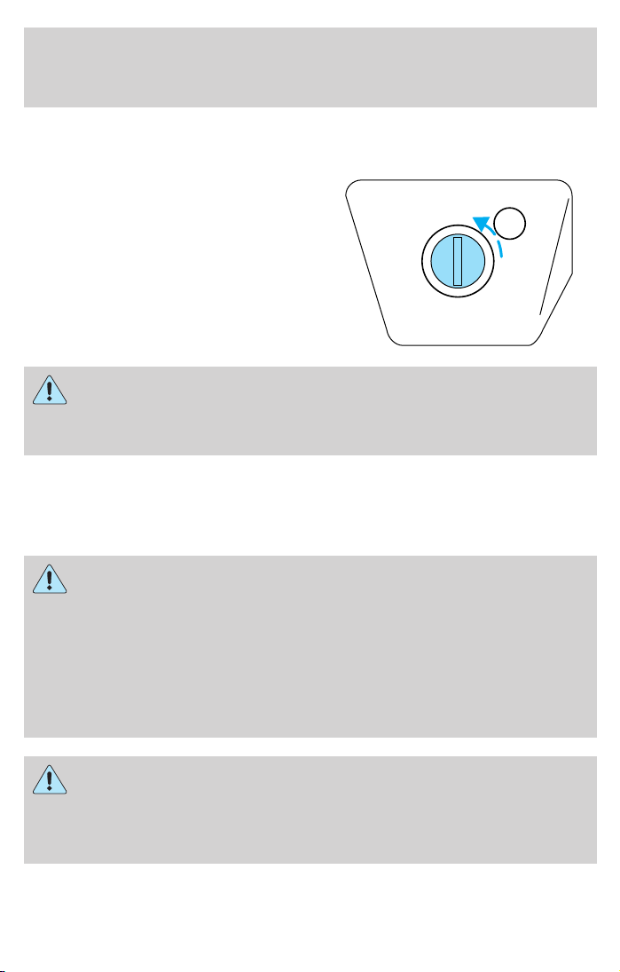
Seating and Safety Restraints
Turning the passenger air bag back on
The passenger air bag remains OFF until you turn it back ON.
1. Insert the ignition key and turn
the switch to ON.
2. The OFF light will briefly
illuminate when the ignition is
turned to ON. This indicates that
the passenger air bag is operational.
PASSENGER AIRBAG
If the OFF light is illuminated when the passenger air bag
ON/OFF switch is in the ON position and the ignition switch is
ON, have the passenger air bag ON/OFF switch serviced at your Ford
or Lincoln-Mercury dealer immediately.
The passenger side air bag should always be ON (the air bag OFF light
should not be illuminated) unless the passenger is a person who meets
the requirements stated either in Category 1, 2 or 3 of the
NHTSA/Transport Canada deactivation criteria which follows.
The safety belts for the driver and right front passenger seating
positions have been specifically designed to function together
with the air bags in certain types of crashes. When you turn OFF your
air bag, you not only lose the protection of the air bag, you also may
reduce the effectiveness of your safety belt system, which was
designed to work with the air bag. If you are not a person who meets
the requirements stated in the NHTSA/Transport Canada deactivation
criteria turning OFF the air bag can increase the risk of serious injury
or death in a collision.
ON
OFF
OFF
Always use safety belts and child restraints properly. If a child in
a rear facing infant seat must be transported in front, the
passenger air bag must be turned OFF. This is because the back of the
infant seat is too close to the inflating air bag and the risk of a fatal
injury to the infant when the air bag inflates is substantial.
93
Page 94

Seating and Safety Restraints
The vast majority of drivers and passengers are much safer with an air
bag than without. To do their job and reduce the risk of life threatening
injuries, air bags must open with great force, and this force can pose a
potentially deadly risk in some situations, particularly when a front seat
occupant is not properly buckled up. The most effective way to reduce
the risk of unnecessary air bag injuries without reducing the overall
safety of the vehicle is to make sure all occupants are properly
restrained in the vehicle, especially in the front seat. This provides the
protection of safety belts and permits the air bags to provide the
additional protection they were designed to provide. If you choose to
deactivate your air bag, you are losing the very significant risk reducing
benefits of the air bag and you are also reducing the effectiveness of the
safety belts, because safety belts in modern vehicles are designed to
work as a safety system with the air bags.
Read all air bag Warning labels in the vehicle as well as the other
important air bag instructions and Warnings in this Owner’s Guide.
NHTSA deactivation criteria (excluding Canada)
1. Infant. An infant (less than 1 year old) must ride in the front seat
because:
• the vehicle has no rear seat;
• the vehicle has a rear seat too small to accommodate a rear-facing
infant seat; or
• the infant has a medical condition which, according to the infant’s
physician, makes it necessary for the infant to ride in the front so that
the driver can constantly monitor the child’s condition.
2. Child age 1 to 12. A child age 1 to 12 must ride in the front seat
because:
• the vehicle has no rear seat;
• although children ages 1 to 12 ride in the rear seat(s) whenever
possible, children ages 1 to 12 sometimes must ride in the front
because no space is available in the rear seat(s) of the vehicle; or
• the child has a medical condition which, according to the child’s
physician, makes it necessary for the child to ride in the front seat so
that the driver can constantly monitor the child’s condition.
3. Medical condition. A passenger has a medical condition which,
according to his or her physician:
• causes the passenger air bag to pose a special risk for the passenger;
and
94
Page 95

Seating and Safety Restraints
• makes the potential harm from the passenger air bag in a crash
greater than the potential harm from turning OFF the air bag and
allowing the passenger, even if belted, to hit the dashboard or
windshield in a crash.
This vehicle has special energy management safety belts for the
driver and/or right front passenger. These particular belts are
specifically designed to work with air bags to help reduce the risk of
injury in a collision. The energy management safety belt is designed to
give or release additional belt webbing in some accidents to reduce
concentration of force on an occupant’s chest and reduce the risk of
certain bone fractures and injuries to underlying organs. In a crash, if
the air bag is turned OFF, this energy management safety belt might
permit the person wearing the belt to move forward enough to incur a
serious or fatal injury. The more severe the crash, and the heavier the
occupant, the greater the risk. Be sure the air bag is turned ON for any
person who does not qualify under the NHTSA deactivation criteria.
Transport Canada deactivation criteria (Canada Only)
1. Infant: An infant (less than 1 year old) must ride in the front seat
because:
• the vehicle has no rear seat;
• the rear seat in the vehicle cannot accommodate a rear-facing infant
seat; or
• the infant has a medical condition which, according to the infant’s
physician, makes it necessary for the infant to ride in the front seat so
that the driver can monitor the infant’s condition.
2. Child age 12 or under: A child age 12 or under must ride in the
front seat because:
• the vehicle has no rear seat;
• although children age 12 and under ride in the rear seat whenever
possible, children age 12 and under have no option but to sometimes
ride in the front seat because rear seat space is insufficient; or
• the child has a medical condition that, according to the child’s
physician, makes it necessary for the child to ride in the front seat so
that the driver can monitor the child’s condition.
3. Medical condition: A passenger has a medical condition that,
according to his or her physician:
• poses a special risk for the passenger if the air bag deploys; and
95
Page 96

Seating and Safety Restraints
• makes the potential harm from the passenger air bag deployment
greater than the potential harm from turning OFF the air bag and
experiencing a crash without the protection offered by the air bag.
This vehicle has special energy management safety belts for the
driver and/or right front passenger. These particular belts are
specifically designed to work with air bags to help reduce the risk of
injury in a collision. The energy management safety belt is designed to
give or release additional belt webbing in some accidents to reduce
concentration of force on an occupant’s chest and reduce the risk of
certain bone fractures and injuries to underlying organs. In a crash, if
the air bag is turned OFF, this energy management safety belt might
permit the person wearing the belt to move forward enough to incur a
serious or fatal injury. The more severe the crash, and the heavier the
occupant, the greater the risk. Be sure the air bag is turned ON for any
person who does not qualify under the Transport Canada deactivation
criteria.
SAFETY RESTRAINTS FOR CHILDREN
See the following sections for directions on how to properly use safety
restraints for children. Also see Air bag supplemental restraint system
(SRS) in this chapter for special instructions about using air bags.
Important child restraint precautions
You are required by law to use safety restraints for children in the U.S.
and Canada. If small children ride in your vehicle (generally children who
are four years old or younger and who weigh 18 kg [40 lbs] or less), you
must put them in safety seats made especially for children. Check your
local and state or provincial laws for specific requirements regarding the
safety of children in your vehicle.
Never let a passenger hold a child on his or her lap while the
vehicle is moving. The passenger cannot protect the child from
injury in a collision.
Always follow the instructions and warnings that come with any infant or
child restraint you might use.
Do not install a child seat in a center facing jump seat.
96
Page 97

Seating and Safety Restraints
Children and safety belts
If the child is the proper size, restrain the child in a safety seat. Children
who are too large for child safety seats (as specified by your child safety
seat manufacturer) should always wear safety belts.
Follow all the important safety restraint and air bag precautions that
apply to adult passengers in your vehicle.
If the shoulder belt portion of a combination lap and shoulder belt can
be positioned so it does not cross or rest in front of the child’s face or
neck, the child should wear the lap and shoulder belt. Moving the child
closer to the center of the vehicle may help provide a good shoulder belt
fit.
Do not leave children, unreliable adults, or pets unattended in
your vehicle.
Child booster seats
Children outgrow a typical convertible or toddler seat when they weigh
40 pounds and are around 4 years of age. Although the lap/shoulder belt
will provide some protection, these children are still too small for
lap/shoulder belts to fit properly, which could increase the risk of serious
injury.
To improve the fit of both the lap and shoulder belt on children who
have outgrown child safety seats, Ford Motor Company recommends use
of a belt-positioning booster.
Booster seats position a child so that safety belts fit better. They lift the
child up so that the lap belt rests low across the hips and the knees
bend comfortably. Booster seats also make the shoulder belt fit better
and more comfortably for growing children.
When children should use booster seats
Children need to use booster seats from the time they outgrow the
toddler seat until they are big enough for the vehicle seat and
lap/shoulder belt to fit properly. Generally this is when they weigh about
80 lbs (about 8 to 12 years old).
97
Page 98

Seating and Safety Restraints
Booster seats should be used until you can answer YES to ALL of these
questions:
• Can the child sit all the way back
against the vehicle seat back with
knees bent comfortably at the
edge of the seat without
slouching?
• Does the lap belt rest low across the hips?
• Is the shoulder belt centered on the shoulder and chest?
• Can the child stay seated like this for the whole trip?
Types of booster seats
There are two types of belt-positioning booster seats:
• Those that are backless.
If your backless booster seat has a
removable shield, remove the
shield and use the lap/shoulder
belt. If a seating position has a
low seat back and no head
restraint, a backless booster seat
may place your child’s head (top
of ear level) above the top of the
seat. In this case, move the
backless booster to another
seating position with a higher seat back and lap/shoulder belts.
• Those with a high back.
If, with a backless booster seat,
you cannot find a seating position
that adequately supports your
child’s head, a high back booster
seat would be a better choice.
Both can be used in any vehicle in a seating position equipped with
lap/shoulder belts if your child is over 40 lbs.
98
Page 99

Seating and Safety Restraints
The shoulder belt should cross the chest, resting snugly on the center of
the shoulder. The lap belt should rest low and snug across the hips,
never up high across the stomach.
If the booster seat slides on the vehicle seat, placing a rubberized mesh
sold as shelf or carpet liner under the booster seat may improve this
condition.
The importance of shoulder belts
Using a booster without a shoulder belt increases the risk of a child’s
head hitting a hard surface in a collision. For this reason, you should
never use a booster seat with a lap belt only. It is best to use a booster
seat with lap/shoulder belts in the back seat- the safest place for children
to ride.
Follow all instructions provided by the manufacturer of the
booster seat.
Never put the shoulder belt under a child’s arm or behind the
back because it eliminates the protection for the upper part of
the body and may increase the risk of injury or death in a collision.
Never use pillows, books, or towels to boost a child. They can
slide around and increase the likelihood of injury or death in a
collision.
SAFETY SEATS FOR CHILDREN
99
Page 100

Seating and Safety Restraints
Child and infant or child safety seats
Use a safety seat that is recommended for the size and weight of the
child. Carefully follow all of the manufacturer’s instructions with the
safety seat you put in your vehicle. If you do not install and use the
safety seat properly, the child may be injured in a sudden stop or
collision.
When installing a child safety seat:
• Review and follow the information
presented in the Air bag
supplemental restraint system
(SRS) section in this chapter.
• Use the correct safety belt buckle
for that seating position (the
buckle closest to the direction the
tongue is coming from).
• Insert the belt tongue into the
proper buckle until you hear a
snap and feel it latch. Make sure the tongue is securely fastened in the
buckle.
• Keep the buckle release button pointing up and away from the safety
seat, with the tongue between the child seat and the release button,
to prevent accidental unbuckling.
• Place seat back in upright position.
• Put the safety belt in the automatic locking mode. Refer to Automatic
locking mode (passenger side front and outboard rear seating
positions) (if equipped) section in this chapter.
Ford recommends the use of a child safety seat having a top tether
strap. Install the child safety seat in a seating position with a tether
anchor. For more information on top tether straps, refer to Attaching
child safety seats with tether straps. in this chapter.
Carefully follow all of the manufacturer’s instructions included
with the safety seat you put in your vehicle. If you do not install
and use the safety seat properly, the child may be injured in a sudden
stop or collision.
100
 Loading...