

Page 1

Table of contents
Introduction 2
Instrumentation 3
Controls and features 9
Charging 13
Starting 23
Driving 26
Roadside emergencies 32
Maintenance and care 46
Capacities and specifications 56
Accessories 58
Index 63
All rights reserved. Reproduction by any means, electronic or mechanical
including photocopying, recording or by any information storage and retrieval
system or translation in whole or part is not permitted without written
authorization from Ford Motor Company. Ford may change the contents without
notice and without incurring obligation.
Copyright © 2000 Ford Motor Company
1
Page 2

Introduction
WELCOME TO THE RANGER ELECTRIC VEHICLE
The Ranger Electric Vehicle is very similar to the gas-powered Ranger in
appearance, interior and controls. The Ranger Electric Vehicle was built
to be transparent from the gas-powered Ranger. There are enough
differences that you should read this manual. Operation is the same, but
some functions are different. The regular Ranger owner’s manual covers
common systems. This Owner’s Guide Supplement contains the
information specific to the Ranger Electric Vehicle.
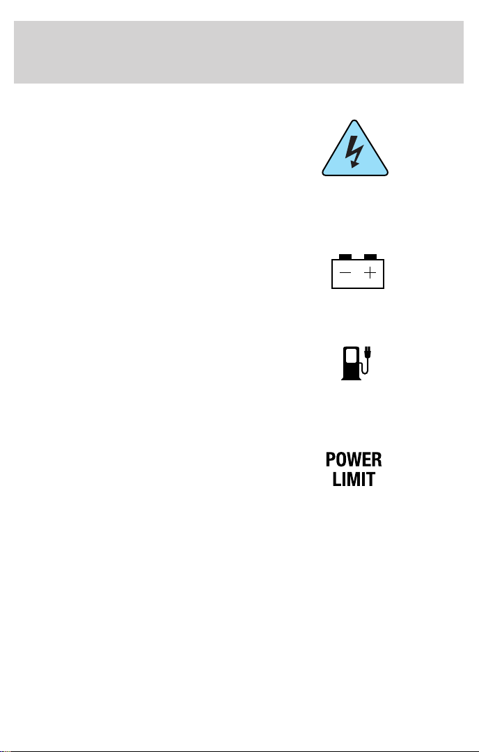
ICONS
The warning icon. Read the following section on Warnings for a full
explanation.
WARNINGS
Provide information which may reduce the risk of personal injury or
prevent possible damage to others, your vehicle and its equipment.
INFORMATION ABOUT THIS GUIDE
The information found in this guide was in effect at the time of printing.
Ford may change the coctents without notice and without incurring
obligation.
2
Page 3

Instrumentation
WARNING LIGHTS AND CHIMES
Service indicator lamp
The service indicator lamp indicates
that a vehicle malfunction has
occurred. The vehicle should be
returned to an authorized Ford
Electric Vehicle (EV) Dealer for service.
Brake warning lamp
The brake warning lamp illuminates
when there is a regenerative braking
system malfunction, low fluid level
in the master cylinder or low fluid
pressure in the hydraulic lines, or
when the parking brake is engaged. If the lamp remains illuminated after
the parking brake is fully released and the master cylinder is full, the
vehicle should be taken to an authorized Ford EV Dealer.
Charging lamp
The charging lamp illuminates when
the key is turned to the ON or
START position while the vehicle is
connected to the power control station (PCS). If the lamp flashes when
the key is in the ON position, there is a vehicle malfunction and the
drive battery cannot be charged. Confirm the vehicle is in park and the
PCS cord is properly attached. If the vehicle is in P (Park) and the PCS
cord is properly connected and the charging lamp continues to flash,
then the vehicle should be taken to an authorized Ford EV Dealer.
!
BRAKE
Low oil pressure lamp
The low oil pressure lamp indicates
that the transaxle oil lubrication
system is operating below the
desired pressure. Oil cannot be
added by the owner. The vehicle
should be returned to an authorized Ford EV Dealer as soon as possible.
Driving in excess of 50 miles to reach an authorized dealer may damage
the transaxle.
3
Page 4
Instrumentation
Electrical hazard warning lamp
The electrical hazard warning lamp
indicates a malfunction in the
high-voltage system. The vehicle will
not charge and must be returned to
an authorized Ford EV Dealer
immediately.
Auxiliary battery lamp
The auxiliary battery lamp indicates
there is an auxiliary battery
charging malfunction. Return the
vehicle to an authorized Ford EV
Dealer immediately.
Low fuel lamp
The low fuel lamp indicates that the
vehicle’s drive battery has reached a
10% state of charge. The vehicle
must be placed on charge. The
indicator will flash when the battery reaches a 0% state of charge.
Power limit lamp
The power limit lamp indicates a
system fault or reduced vehicle
performance to conserve remaining
drive battery power. As the vehicle
nears complete discharge, the power limit lamp will illuminate.
High-voltage accessories (A/C and heat) will be disabled. You will notice
a decrease in vehicle performance and you must return to a PCS (power
control station) immediately. The lamp will begin to flash and the
performance of the vehicle will be severely limited. The vehicle will
continue to operate until the drive battery is completely drained;
however, driving under this condition will damage the battery, resulting
in reduced battery life.
4
Page 5
Instrumentation
Anti-lock brake system (ABS) lamp
The ABS lamp indicates that there
is a malfunction with the ABS. If the
light stays on or continues to flash
after the vehicle is started, return
the vehicle to an authorized Ford
EV Dealer for service.
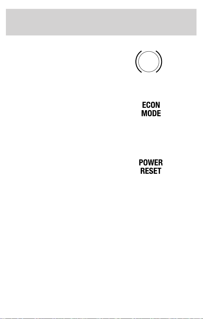
Econ mode lamp
The econ mode lamp indicates that
the gearshift is in the E (Economy)
position. This mode is recommended
for urban traffic and will improve
range by increasing the effects of regenerative braking and limiting top
speed to 105 km/h (65 mph). The D (Drive) position is recommended for
highway operation at steady speeds.
Power reset lamp
The power reset lamp indicates that
the inertia shutoff switch has been
tripped and all high-voltage power
has been disconnected and power
has been limited to the traction battery. If there is no damage to the
vehicle, reset the switch to reactivate the high-voltage power systems.
ABS
5
Page 6
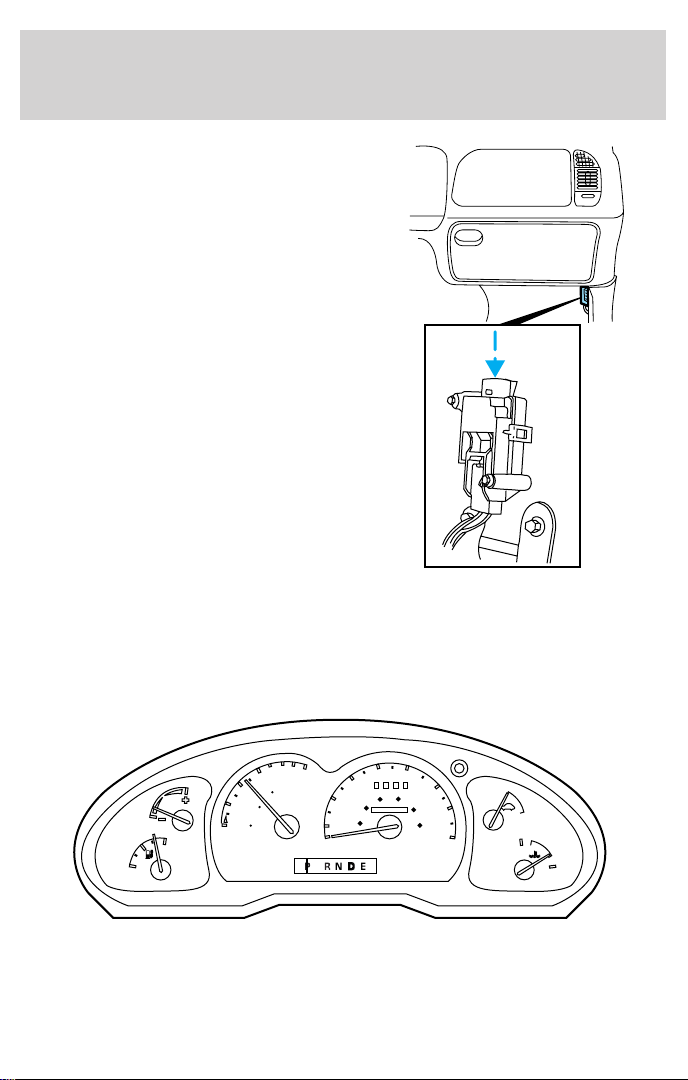
Instrumentation
The inertia shutoff switch is located
by the passenger kick panel. If there
is damage to the vehicle, have the
vehicle towed to an authorized Ford
EV Dealer.
RANGER EV FOR MEXICO AND CANADA
The instrument cluster on the Ranger EV for Mexico and Canada will be
equipped with metric gauges. All gauges operate as described below.
GAUGES
6
40
MPH
30
20
40
50
60 80
000000
60
100
70
120
km/h
ON
80
OFF
H
C
0
6
100
4
MILES
0
DISTANCE
50
TO EMPTY
0
2
km
0
0
20
10
ECON
F
E
Page 7
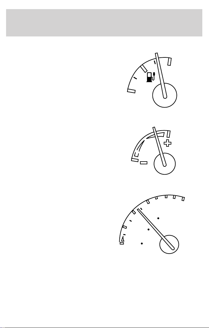
Battery state of charge gauge
The battery state of charge gauge is
the equivalent of a fuel gauge on a
gasoline-powered vehicle. F (Full)
indicates that the battery is
completely charged. E (Empty)
indicates the battery has been
discharged to the point where
additional operation will damage
vehicle systems.
Economy gauge
The economy gauge provides
information about the vehicle’s
energy usage. Economical usage of
the vehicle is indicated by the gauge
reading near the plus (+) side and
will maximize the vehicle’s range.
Distance to empty gauge
The distance to empty gauge
estimates the remaining distance the
vehicle can travel before requiring a
drive battery recharge. The gauge
reading is based on remaining drive
battery energy, driving conditions
and recent vehicle usage.
Instrumentation
E
ECON
0
6
100
4
0
DISTANCE
50
TO EMPTY
km
0
MILES
0
2
0
F
7
Page 8
Instrumentation
Motor enabled gauge
The motor enabled gauge indicates
that the vehicle is ready to drive.
Turning the ignition switch to the
full START position and releasing
will turn the vehicle on, and the
gauge will move to the ON position.
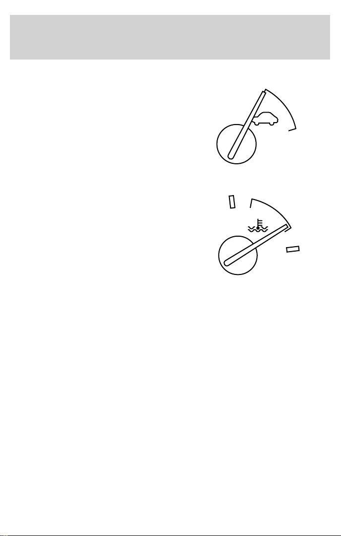
Temperature gauge
The temperature gauge indicates
the temperature of the vehicle’s
components. Unlike conventional
temperature gauges, it does not
start cold and move to normal. The
gauge sits at normal and moves to
hot or cold when there is a problem.
If the gauge moves to H (Hot),
vehicle performance will be limited
until the coolant temperature or drive battery temperature returns to
normal. The vehicle should be stopped and plugged into a PCS until it
has cooled down. The vehicle may need servicing. If the gauge moves to
C (Cold), the vehicle may have an extended charge time and a reduced
driving range.
ON
OFF
H
C
8
Page 9
Controls and features
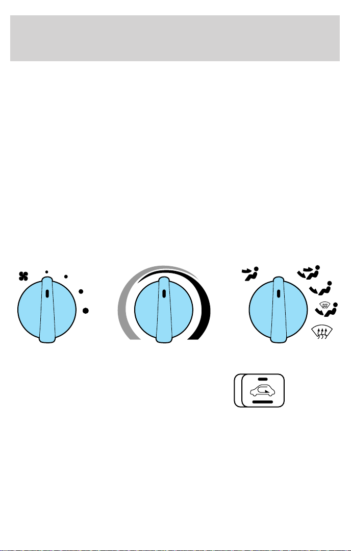
CLIMATE CONTROL SYSTEM
Your vehicle is equipped with an automatic temperature control (ATC)
system designed to maintain a selected temperature with a combination
A/C-Heater system.
Air conditioning (A/C) and heater controls
The control for your air conditioning and heater system is located at the
center of the instrument panel below the radio and will operate in the
KEY-ON position. Your air conditioner and heater will heat and/or cool
your vehicle interior depending on the function position and temperature
you select. The mode selector knob allows you to select heating or
cooling, and determine where the air will be directed. The temperature
control knob setting determines the desired interior temperature of the
vehicle. To turn your air conditioner or heater system on, select any
position except OFF. This will turn the fan on and allows air flow into
the vehicle. To turn your air conditioner or heater system off, select OFF.
This will turn the fan off and stop airflow from coming into the vehicle.
OFF
A/C
MAX
A/C
Recirculation switch
The recirculation switch is located
at the center of the instrument
panel just right of the radio. It
allows switching from outside air to
recirculated air in Panel,
Panel/Floor, and Floor modes. The recirculation switch operates for five
minutes, then shuts off. If more recirculation operation is desired, press
the control again. Note that in MAX A/C and A/C modes, the function is
automatic (stays in recirculation mode) and cannot be switched off. A
table of recirculation switch operation follows.
9
Page 10
Controls and features
Recirculation Switch Operation
Icon Mode Recirculation
MAX A/C Max A/C Automatic
A/C A/C Automatic
OFF OFF Not Available
Floor/Defrost Not Available
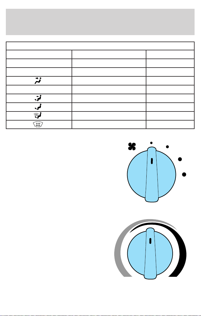
Fan speed knob
The left knob on the control is the
fan control knob, which controls the
volume of air flow. Rotate the knob
to the right to increase fan speed
and increase the amount of air
entering the vehicle. Four fan speed
positions are available and are
indicated by dots beside the control
knob. The largest dot is the
high-speed position.
Panel Selectable
Panel/Floor Selectable
Floor Selectable
Defrost Not Available
Temperature control knob
The temperature control knob is the
rotating knob located at the center
of the control with tapered red and
blue bands surrounding most of the
knob. The wide red part of the band
(full right) is the warm temperature
area. The wide blue part of the band
(full left) is the cool temperature
area. Any position selected between
full right and full left will give a
temperature between maximum
heating 29°C (84°F) and maximum cooling 18°C (64°F) (A/C and MAX
A/C modes only).
10
Page 11
Controls and features
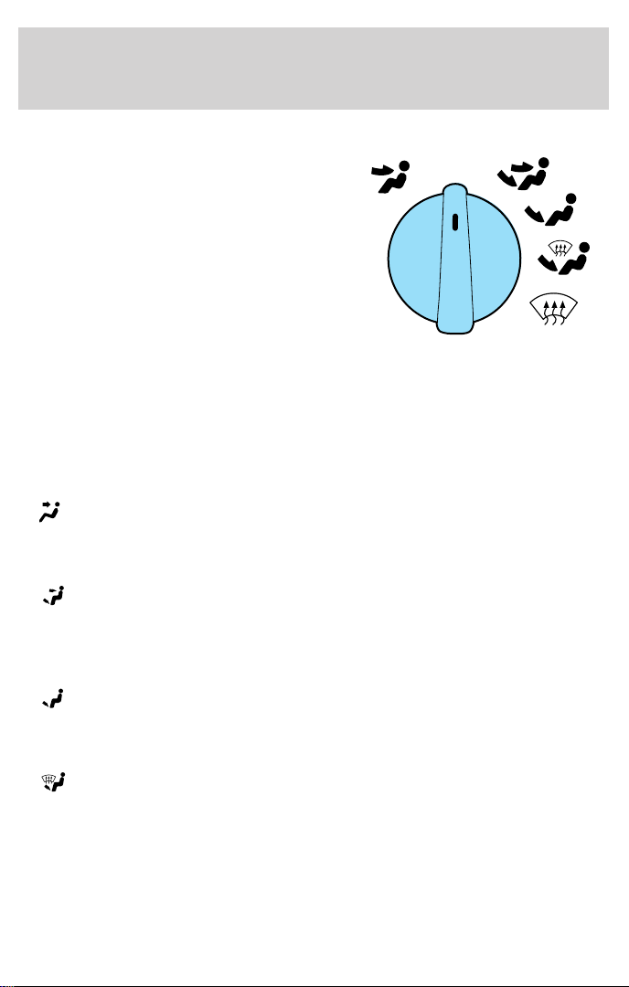
Mode selector knob
The right knob on the control is the
mode selector, which controls the
direction of the airflow inside the
vehicle.
• MAX A/C-Select to distribute recirculated air through the instrument
panel registers. This position produces cool air more rapidly to provide
faster cooling of your vehicle. Using MAX A/C may be noisier and less
economical than A/C.
• A/C-Select to distribute cool recirculated air through the instrument
panel registers. This position should be used for cooling except when
it is extremely hot or fast cooling of the vehicle is needed.
•
•
•
•
(panel)-Select to distribute outside air or recirculated air through
the instrument panel registers. The air may be heated based on
temperature selection. The air cannot be cooled below the outside
temperature regardless of the temperature setting.
(panel and floor)-Select to distribute outside air or recirculated
air through the instrument panel registers and to the floor ducts at
the same time. The air may be heated based on temperature selection.
The air cannot be cooled below the outside temperature regardless of
the temperature setting.
(floor)-Select to distribute outside air or recirculated air through
the floor ducts. The air may be heated based on temperature
selection. The air cannot be cooled below the outside temperature
regardless of the temperature setting.
(floor and defrost)-Select to distribute outside air through the
floor ducts and the windshield defroster ducts at the same time. If the
outside air temperature is 10°C (50°F) or warmer, the air conditioner
will dehumidify the air to prevent fogging. The air may be heated
and/or cooled based on temperature selection.
A/C
MAX
A/C
OFF
11
Page 12

Controls and features
• (defrost)-Select to distribute outside air through the windshield
defroster ducts. Defrost can be used to clear ice or fog from the
windshield. If the outside air temperature is 10°C (50°F) or warmer
the air conditioner will dehumidify the air to prevent fogging. The air
may be heated and/or cooled based on temperature selection.
Operating tips
• In humid weather, select defrost before driving. This prevents your
windshield from fogging. After a few minutes of operation, you may
select another function.
• Remove any snow, ice or leaves from the air intake area of your heater
system that could block the air intake. The intake area is located at
the bottom of the windshield.
• If temperatures below -18°C (0°F), select recirculation before driving.
This will help warm the vehicle interior and minimize degraded
performance at low outside temperatures.
• The use of climate controls will reduce the vehicle’s range. Limit the
use of maximum heating and cooling of the vehicle interior.
12
Page 13

Charging
CHARGING
Charging the Ford Ranger Electric Vehicle is a safe, simple process.
In-garage charging of the Ranger Electric Vehicle has received UL
approval. To maximize range, the vehicle should be connected to a
power control station (PCS) whenever possible to keep the battery fully
charged.
A conductive power control station (PCS) is required to recharge your
Ranger Electric Vehicle. The PCS consists of a “smart” box and a
connector and cable assembly that safely conducts AC power from the
utility supply grid to the vehicle inlet (located at the right front of the
vehicle, next to the right headlamp). An important feature of the PCS is
an integrated control pilot circuit, which performs safety functions such
as verifying the vehicle is present and safely connected, start/stop
control, confirming the smart box is ready to send power, confirming the
vehicle is ready to accept power, and continuously verifying the presence
of an equipment ground. The PCS supplies the power commanded by
the vehicle.
These stations will be in private locations (for example, residential or
fleet garages) or in public sites (for example, shopping malls,
restaurants, parking lots and so on). The PCS uses a 40 amp, 240 volt,
AC electrical supply.
The customer is responsible for ordering the PCS and getting it installed.
Your Ford Dealer will provide information on how to purchase and how
to get your PCS installed.
Consult your PCS owner’s manual for specific instruction on using your
PCS. Additional installations or service requirements that you might need
should be performed by a full service installer. Contact your Ford dealer
for a complete listing. If your installer finds any PCS malfunctions,
contact the PCS manufacturer.
Always follow charging instructions carefully. Failure to do so
may result in vehicle damage, personal injury or death.
13
Page 14
Charging
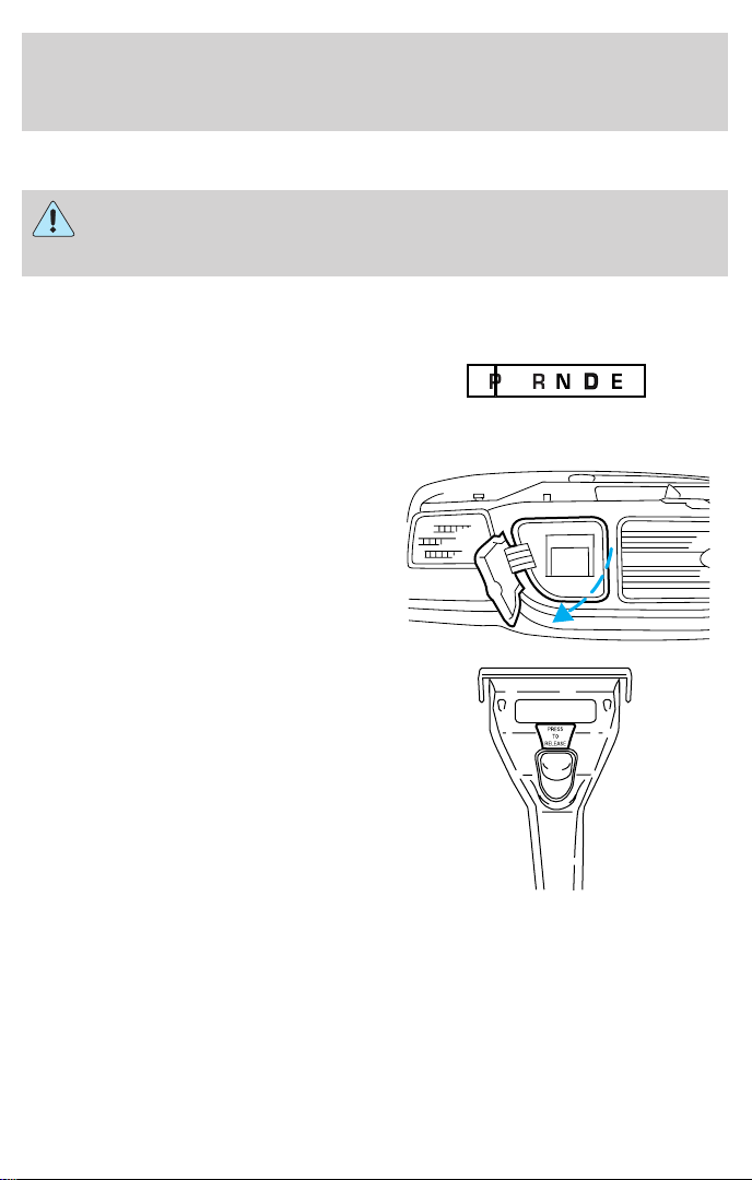
To connect the PCS:
Always set the parking brake fully. Make sure the gearshift lever
is placed in P (Park) position. Turn off the “ignition” whenever
you leave your vehicle.
1. Park the Ranger Electric Vehicle. The vehicle’s charge inlet is at the
right front of the vehicle in the grille, next to the right headlamp.
2. Place the gearshift lever in P
(Park) and set the parking brake.
3. Turn the “ignition” to LOCK and remove the key from the “ignition.”
4. Open the charge inlet access door
in the front grille. The door is
hinged toward the right headlamp
and opens in the same manner as
the fuel filler door.
5. Pick up the PCS connector and
position it so that the release button
is facing upwards.
6. Align the PCS connector to the charge inlet, fully insert the connector
and make sure that the tabs on both sides of the connector engage the
slots in the inlet.
14
Page 15

Charging
7. Gently push the connector down,
toward the bumper, until you hear a
click. The click means that the
connector is locked into the inlet.
8. The time required to charge the vehicle depends on the battery
temperature and the state of charge when the vehicle is plugged in. The
normal charge time is 6–8 hours. Reduced supply voltage, from the
recommended 240 volts, may adversely affect the normal charge time.
Estimated charge time
The amount of time required to fully charge the battery pack varies
depending upon the beginning state of charge and battery temperature.
Note that battery temperature is not necessarily the same as outside
temperature. The use of outside temperature to plan charge times,
however, is the most straightforward approach.
Typically it will take 6–8 hours for the vehicle to fully charge from
“empty” to “full.” Use the battery state of charge gauge as a guide to
assess whether enough charge time was allowed. If the gauge does not
indicate “full” when the “ignition” is moved to the ON position, one of
the following may have happened:
• The battery pack may be too warm or too cold. Charge times can
increase to 10 hours or more for warmer or cooler batteries. In sever
temperature conditions (battery temperature less than 5°C [41°F], or
greater than 60°C [140°F] for the lead-acid type and less than
–25°C [–13°F] or greater than 45°C [113°F] for the nickel metal
hydride type) the vehicle will not charge at all.
• The PCS may be malfunctioning.
• The battery pack may be out of electrical balance. The vehicle will
perform a balancing charge, which may take up to four hours for the
lead-acid type or two hours for the nickel metal hydride type over the
normal charging time, and then indicate “full.”
• The gearshift lever was not in P (Park).
15
Page 16

Charging
• The battery pack (lead-acid type only) may be new. Vehicles that have
experienced less than 10 drive/charge cycles need an additional few
hours of charge time.
Refer to charging troubleshooting later in this section.
If none of the above apply, the vehicle should be returned to the PCS to
attempt to complete charging or taken to an authorized Ford EV Dealer.
Lead-acid traction battery
At 25°C (77°F), the drive battery can be charged to 80% capacity in
about three hours; 100% capacity requires approximately six to eight
hours. Completely charging the drive battery is important to ensure
maximum range and battery life. Ford recommended practice is that the
vehicle should always be left on-plug when not in use and be allowed to
fully charge before driving.
Charge time may increase at colder or hotter temperatures. The drive
battery must be above 5°C (41°F) and below 60°C (140°F) before
charging will begin. After being connected to a PCS, the vehicle will
automatically heat or cool the drive battery, as needed. When the battery
reaches the necessary temperature, charging will begin. Following a
complete charge in colder climates, charging will continue at periodic
intervals to maintain the battery at –10°C (14°F).
The Ranger Electric Vehicle should be connected to a PCS
whenever it is not being driven.
If a PCS is not available, the vehicle may be stored off-plug for up to
28 days without suffering permanent damage as long as the initial state
of charge is greater than 50%. The frequency of this type of storage
should be limited to a few occurrences over the life of the vehicle.
Nickel metal hydride traction battery
At 25°C (77°F), the drive battery can be charged to 80% capacity in
about five to six hours; 100% capacity requires approximately six to
eight hours. Completely charging the drive battery is important to ensure
maximum range and battery life. Ford recommended practice is that the
vehicle should always be left on-plug when not in use and be allowed to
fully charge before driving.
Charge time may increase at colder or hotter temperatures. The drive
battery must be above –25°C (–13°F) and below 45°C (113°F) before
charging will begin. After being connected to a PCS, the vehicle will
automatically cool the drive battery as needed. When the battery reaches
16
Page 17
Charging
the necessary temperature, charging will begin. Following a complete
charge in colder climates, charging will continue at periodic intervals to
maintain the battery at –10°C (14°F).
The Ranger Electric Vehicle should be connected to a PCS
whenever it is not being driven.
If a PCS is not available, the vehicle may be stored off-plug for up to
28 days without suffering permanent damage as long as the initial state
of charge is greater than 50%. The frequency of this type of storage
should be limited to a few occurrences over the life of the vehicle.
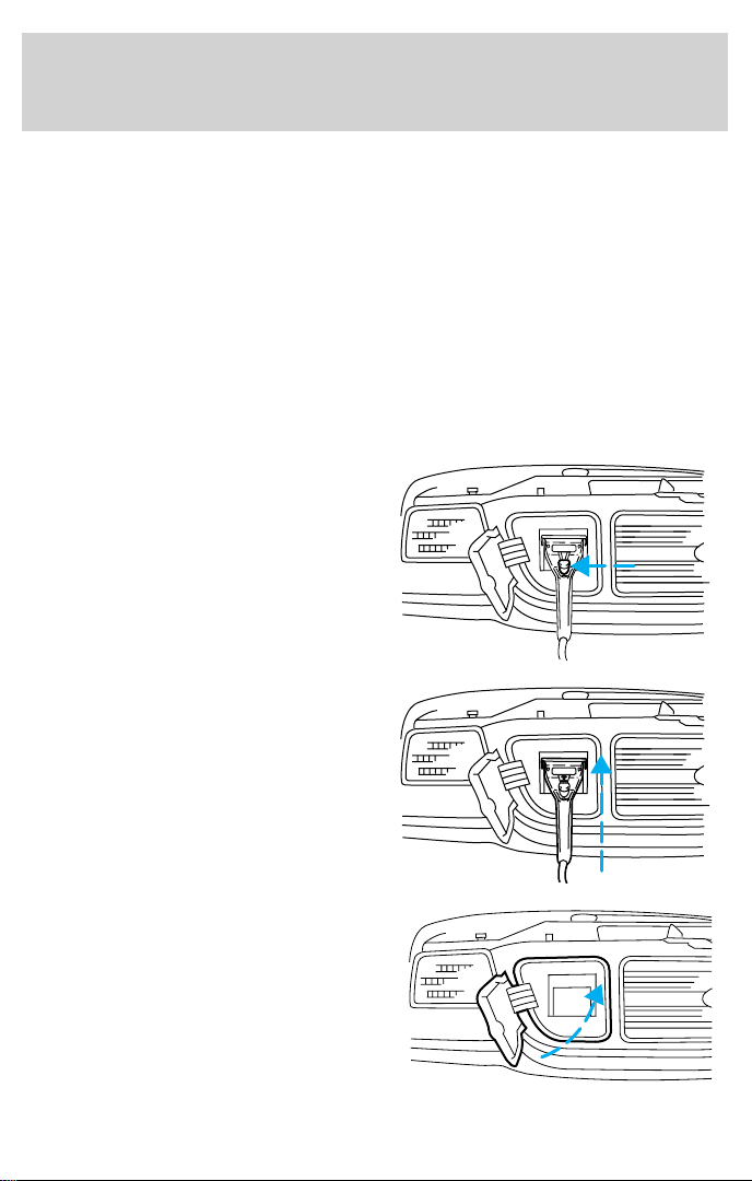
To disconnect the PCS:
1. Push the STOP button on the PCS.
2. Grasp the charge connector and
press the button in the center of the
handle.
3. Pull the charge connector upward
and pull it out of the inlet.
4. Close the charge inlet access door
in the front grille.
17
Page 18

Charging
5. Return the connector and cable
to their proper location.
Charging troubleshooting using SCI systems (SCIT) equipment
If your vehicle fails to charge, follow this procedure to determine if your
Power Control Station (PCS) is operating properly:
1. Make note of any lights that are flashing or steadily illuminated on
your PCS.
2. Determine if the charge connector is properly inserted in the vehicle
inlet and locked in place.
3. Is the charge interrupt light illuminated? If yes, your vehicle may have
undergone a series of faults which forced the PCS to terminate the
charge process.
• Push the stop button.
• Unplug the connector from the vehicle inlet, to clear the fault.
• Inspect the cable and connector for any signs of possible damage (i.e.
cuts, tears or breaks in the cable insulation). If damage is found, stop
any further attempts to charge the vehicle and call the PCS
manufacturer for repair.
• If the cable and connector are undamaged reconnect the PCS to the
vehicle inlet. Is the charge interrupt light still illuminated or flashing?
Consult your authorized Ranger EV dealer to determine possible
vehicle fault.
4. Is the service light illuminated? If yes,
• Disconnect the charge connector vehicle inlet.
• Turn off the power to your PCS at the service or disconnect panel.
Turning off the power may allow the PCS to clear the fault.
18
Page 19

Charging
• Turn the power back on and reconnect the PCS to the vehicle inlet. Is
the service light still illuminated? If so, call the PCS manufacturer for
repair or replacement. The toll free number is located on the PCS.
Charging troubleshooting using Electric Vehicle Infrastructure
(EVI
T
) equipment
If your vehicle fails to charge follow this procedure to determine if your
Power Control Station (PCS) is operating properly:
1. Make note of any lights that are illuminated or any messages being
issued by your PCS.
2. Determine if the charge connector is properly inserted in the vehicle
inlet and locked in place.
3. Is the protection light illuminated? If yes, your vehicle may have
undergone a series of faults which forced the PCS to terminate the
charge process.
• Push the stop button.
• Unplug the PCS charge connector from the vehicle inlet, to clear the
fault.
• Inspect the charge cable and connector for any signs of possible
damage (i.e. cuts, tears or breaks in the cable insulation). If damage is
found, stop any further attempts to charge the vehicle and call the
PCS manufacturer for repair.
• If the charge cable and connector are undamaged, reconnect the
vehicle. Is the charge interrupt light illuminated or flashing? Consult
your authorized Ranger EV dealer to determine possible fault.
4. Is the service light illuminated? If yes,
• Disconnect the PCS charge connector from the vehicle inlet.
• Turn off the power to your PCS at the service or disconnect panel.
Turning off the power may allow the PCS to clear the fault.
• Turn the power back on and reconnect the PCS to the vehicle. Is the
service light still illuminated? If so, call the PCS manufacturer for
repair or replacement.
• Are the ready or charging lights illuminated? If yes, your PCS is
operating correctly. Consult your authorized Ranger EV dealer to
determine vehicle fault.
19
Page 20

Charging
• If turning the PCS power on and off or unplugging and plugging the
charge connector in the vehicle inlet does not cause any of the lights
to illuminate on the PCS, the PCS has either failed or has a damaged
charge cord. Call the PCS manufacturer for repair or replacement. The
toll free number is located on the PCS.
The Ranger Electric Vehicle should be connected to a PCS
whenever it is not being driven.
Battery pack heating/cooling system (lead-acid type)
The battery pack assembly contains 39 eight-volt batteries, wiring, a fan
for ventilation and cooling, a control system and optional heaters for cold
weather climates. These components work automatically when the
vehicle is on-plug charging, and are monitored by the battery pack
control system. Heating and cooling do NOT occur key OFF and off-plug.
The systems are designed to maintain battery pack temperatures when
on-plug as well as during the drive cycle, and may not be able to heat or
cool batteries that have reached excessive temperatures.
Battery temperatures tend to be warmer than outside temperature if driven
and fully charged each day. If left off-plug, the batteries will eventually
equalize to outside underbody temperature, although this process can take
several days to occur. Extended periods off-plug in cold outdoor
temperatures can cause the batteries to take several days to warm up.
The heaters maintain the battery pack at approximately 20° (68°F) and
are effective to at least –20°C (–4°F). The cooling fan utilizes outside air,
and therefore cooling effectiveness depends upon the temperature
difference between the batteries and outside air. The cooling system
works to maintain the batteries at approximately 35°C (95°F).
Equalization
The battery control system will periodically equalize the charge in the
batteries, which smooths out battery-to-battery differences in the ability to
deliver energy. This results in optimum range and battery life. Equalization
is automatically performed approximately every three weeks. The fuel
gauge will indicate if insufficient charge time has been allowed.
The Ranger Electric Vehicle should be connected to a PCS
whenever it is not being driven.
20
Page 21

Charging
Battery pack heating/cooling system (nickel metal hydride type)
The battery pack assembly contains 25 twelve-volt batteries, wiring, two
fans for ventilation and cooling and a control system. Following a
complete charge, battery heating is accomplished by periodically
overcharging the batteries to maintain a minimum acceptable
temperature. These components work automatically when the vehicle is
on-plug charging, and are monitored by the battery pack control system.
Heating and cooling do NOT occur key OFF and off-plug. The systems
are designed to maintain battery pack temperatures when on-plug as well
as during the drive cycle, and may not be able to heat or cool batteries
that have reached excessive temperatures.
Battery temperatures tend to be warmer than outside temperature if
driven and fully charged each day. If left off-plug, the batteries will
eventually equalize to outside underbody temperature, although this
process can take several days to occur. Extended periods off-plug in cold
outdoor temperatures can cause the batteries to cool to below –25°C
(–13°F) and prevent both charging and self-heating.
The Ranger Electric Vehicle should be connected to a PCS
whenever it is not being driven.
Battery self-heating following a complete charge will maintain the battery
at approximately –10°C (14°F). The cooling fan utilizes outside air, and
therefore cooling effectiveness depends upon the temperature difference
between the batteries and outside air. The cooling system works to
maintain the batteries at approximately 25°C (77°F).
Equalization
The battery control system will periodically equalize the charge in the
batteries, which smooths out battery-to-battery differences in the ability
to deliver energy. This results in optimum range and battery life.
Equalization is automatically performed approximately every three
weeks. The fuel gauge will indicate if insufficient charge time has been
allowed.
The Ranger Electric Vehicle should be connected to a PCS
whenever it is not being driven.
21
Page 22

Charging
Partial recharges
A partial recharge is charging the battery pack to less than 100% state of
charge and can be performed occasionally without loss of range or
performance. However, long term multiple partial charges tend to create
imbalances in battery-to-battery state of charge and are strongly
discouraged. Usage patterns should be planned to include a full recharge
each time the vehicle is discharged. On vehicles equipped with the
nickel-metal hydride drive batteries, a full discharge is recommended
periodically to minimize battery memory effect.
22
Page 23

POSITIONS OF THE IGNITION SWITCH
1. ACCESSORY allows the
accessories such as the radio to
operate while the motor is not
powered up.
2. LOCK locks the steering wheel
gearshift lever. Allows key removal.
LOCK
3. OFF disconnects all high-voltage
power from the traction battery.
ACCESSORY
4. ON, warning lights momentarily
illuminated. Key position when driving.
5. START powers up the motor and
turns the Motor Enable Gauge to
the ON position. Powers up all
high-voltage power from the drive
battery.
STARTING THE RANGER ELECTRIC VEHICLE
1. If connected, disconnect the PCS
plug from the charge inlet and close
the charge inlet access door.
Starting
ON
OFF START
ON
OFF
The car will not start until the plug is removed.
23
Page 24

Starting
1. Make sure all vehicle occupants
have buckled their safety belts. For
more information on safety belts
and their proper usage, refer to the
seating and safety restraints chapter
in the Ranger owner guide.
1. Make sure the parking brake is
set.
2. Make sure the gearshift lever is in
P (Park).
3. Turn the key to the START
position and release. The Motor
Enabled gauge will point to the ON
position, indicating the vehicle is on.
4. Check the drive Battery State of
Charge gauge to confirm that the
drive battery is charged sufficiently
for the planned trip.
24
ON
OFF
F
E
Page 25

5. Pull the release lever to release
the parking brake. The Ranger
electric vehicle is now ready to be
driven.
Starting
25
Page 26

Driving
REGENERATIVE BRAKING
Your Ranger Electric Vehicle uses a unique feature known as
regenerative braking. This is used to simulate the engine braking of an
internal combustion engine and assist the standard brake system while
recovering some of the energy of motion back into the battery.
The standard brake system is designed to fully stop the truck if
regenerative braking is not available.
Once the accelerator pedal is released, the vehicle automatically
decelerates slowly. This deceleration is caused by using the spinning
motor as a generator to create electrical current. This recharges the
traction battery and slows the vehicle. In effect, once the accelerator
pedal is released, the motor changes from an energy user to an energy
producer. When the battery is almost fully charged, the amount of
regenerative braking is limited to avoid overcharging.
Regenerative braking does not take the place of the standard friction
brakes; it only assists them. Regenerative braking has also been designed
to interact with the anti-lock brake system (ABS). Regenerative braking
is disabled when the ABS is activated or the battery is fully charged.
ANTI-LOCK BRAKE SYSTEM (ABS)
A noise from the hydraulic pump motor and pulsation in the brake pedal
may be observed during ABS braking events. Pedal pulsation coupled
with noise while braking under panic conditions or on loose gravel or wet
snowy roads is normal and indicates proper functioning of the brake
system. If the vehicle has continuous vibration or shudder while braking,
felt mainly in the steering wheel, the vehicle most likely needs service.
The ABS operates by detecting the onset of wheel lockup during brake
applications and compensating for this tendency.
ABS warning lamp
The ABS warning lamp in the
instrument cluster illuminates if an
ABS fault is detected.
26
ABS
Page 27

Driving
An ABS fault will also illuminate the
BRAKE warning lamp. The base
hydraulic brake system will still be
effective. Have your vehicle serviced
as soon as possible.
Using ABS
• In an emergency or when maximum efficiency from the ABS is
required, apply continuous full force on the brake pedal. The ABS will
be activated immediately (thus allowing you to retain full steering
control of your vehicle) and (providing there is sufficient space) will
enable you to avoid obstacles and bring the vehicle to a controlled
stop.
• We recommend that you familiarize yourself with this braking
technique. Avoid, however, taking any unnecessary risks.
• Regenerative braking is disabled while ABS is active allowing ABS full
control.
STEERING
Your Ranger Electric Vehicle has variable assist power steering. The
power steering uses energy from the battery to help steer your vehicle.
If the amount of effort needed to steer your vehicle changes at a
constant speed, have the power steering system checked. If the power
steering system breaks down (or if the vehicle is turned off), you can
steer the vehicle manually, but it takes more effort.
Avoid holding the steering wheel to the extreme right or left for more
than five seconds if the vehicle is running.
When starting the vehicle at extremely cold temperatures
(-20°C[–4°F]), a 10–second delay will occur prior to power
steering pump start-up. This will result in a delay of power
steering assist during initial start-up.
!
BRAKE
27
Page 28

Driving
TRANSAXLE OPERATION
Your vehicle is equipped with a brake shift interlock that prevents
shifting of the gearshift lever out of park unless the foot brake is applied.
Step on the brake pedal and pull the gearshift lever towards you and
downward to move the gearshift lever.
Hold the brake pedal down while you move the gearshift lever
from P (Park) to another position. If you do not hold the brake
pedal down, your vehicle may move unexpectedly and injure someone.
P (Park)
Always set the parking
brake fully and make sure
the gearshift is latched in P
(Park). Turn off the ignition
whenever you leave your vehicle.
Always come to a complete stop before shifting into P (Park). Make sure
the gearshift lever is in P (Park).
R (Reverse)
With the gearshift lever in R
(Reverse), the vehicle will move
backward. Always come to a
complete stop before shifting into and out of R (Reverse). Regenerative
braking is applied in reverse too, at a level similar to the D (Drive) gear.
When the drive battery is almost fully charged, the amount of
regenerative braking is limited to avoid overcharging.
N (Neutral)
With the gearshift lever in N
(Neutral), the vehicle can be started
and is free to roll. Hold the brake
pedal down while in this gear to prevent movement.
28
Page 29

Driving
D (Drive)
With the gearshift lever in D
(Drive), the vehicle will move
forward. Top speed is limited to
121 km/h (75 mph). The transaxle operates in forward gear. This
selection is recommended for highway operation. Deceleration from
regenerative braking is commanded when the driver lifts off on the
accelerator pedal or when the brake pedal is pressed. However, when the
battery is almost fully charged, the amount of regenerative braking is
limited.
E (Economy)
With the gearshift lever in E
(Economy), the Ranger operates as
in drive, but the effects of
regenerative braking are increased and top speed is limited to 105 km/h
(65 mph). This selection is recommended for urban operation when
extended driving range is desired. The economy mode is used to
maximize the vehicle’s range. A stronger deceleration from regenerative
braking results from releasing the accelerator pedal. In this regard, it
feels similar to low gear on a typical transmission. When the battery is
almost fully charged, the amount of regenerative braking is limited.
Low charge
As the Ranger Electric Vehicle is
driven, the Battery State of Charge
Gauge indicates the battery’s
remaining charge like a fuel gauge
does on a conventional
gasoline-powered vehicle. When the
gauge approaches the Empty (E)
position, the vehicle should be
connected to a PCS before the drive
battery is completely drained.
If the Ranger is driven while the Battery State of Charge Gauge reads E,
there are two warning lights that illuminate in stages to alert the driver
of the vehicle’s condition.
E
F
29
Page 30

Driving
This is the order of what the driver will see:
1. At a 10% battery state of charge,
the low fuel lamp illuminates.
2. At a 0% battery state of charge, the low fuel lamp flashes. Driving the
vehicle below 0% will damage vehicle systems.
3. The power limit lamp illuminates
to indicate that the vehicle’s
performance is being limited to
conserve remaining battery power.
4. The power limit lamp flashes to indicate that the vehicle’s performance
has been further limited.
Driving the vehicle to complete discharge will damage the battery,
resulting in reduced battery life.
Driving on snow and ice
The regenerative braking system interacts with the ABS so if the wheels
begin to slide, ABS will activate and regenerative braking will be
disabled.
Vehicle coasting distance will increase when regenerative braking
is reduced by ABS activation.
Driving on hill or slope terrain
When driving down hills, regenerative braking may be used to maintain
speed while recovering energy similar to the way engine braking is
typically used. E (Economy) gear provides the maximum amount of
“engine braking,” like low gear in an automatic transmission.
Once the accelerator pedal is released, the vehicle automatically and
slowly decelerates. This deceleration is caused by using the spinning
motor as a generator to create electrical current. This recharges the
traction battery and slows the vehicle. In effect, once the accelerator
pedal is released, the motor changes from an energy user to an energy
producer.
When the battery is fully charged, regenerative braking is eliminated to
prevent overcharging of the traction batteries. As the traction batteries
state of charge begins to diminish with driving usage the amount of
regenerative braking is allowed to increase to assist the standard braking
system.
30
Page 31

Driving
Regenerative braking does not take the place of the standard friction
brakes; it only assists them. Regenerative braking has also been designed
to interact with the anti-lock brake system (ABS). Regenerative braking
is disabled when the ABS is activated.
TRAILER TOWING
The Ranger Electric Vehicle should not be used for towing a trailer.
TONNEAU COVER
The cover is intended to improve energy efficiency at freeway speeds.
Keep all the cover supports in place when the cover is installed to keep
water, snow or ice from accumulating in the center and possibly
damaging the cover.
ENERGY TIPS
The Ranger Electric Vehicle has a customer range of approximately
80 kilometers (50 miles) with the standard lead-acid type traction
battery or approximately 160 kilometers (100 miles) with the optional
nickel metal hydride type traction battery. This range is affected by the
use of vehicle accessories, driving habits and weather conditions. To
maximize the vehicle’s range, follow these steps:
• Use the E (Economy) gear.
• Keep the tires properly inflated to 350 kpa (50 psi).
• Keep payloads as light as possible.
• Avoid frequent full throttle usage.
• Maintain a steady speed while driving.
• Cruise at moderate speeds.
• Select routes that minimize the number of starts and stops
encountered.
• Limit the use of max cooling or heating of the vehicle interior.
• Avoid hard acceleration and deceleration.
• Leave the tonneau cover installed on the bed.
In addition to these steps, connect the Ranger to a Power Control
Station (PCS) whenever it is not being driven. This will keep the
battery as charged as possible.
31
Page 32

Roadside emergencies
INERTIA SHUTOFF SWITCH
If the Power Reset Lamp
illuminates, it indicates that the
inertia shutoff switch has been
activated. If there is no damage to
the vehicle, reset the switch to reactivate the high-voltage power systems
and restart the vehicle.
The inertia shutoff switch is located
by the passenger kick panel. If there
is damage to the vehicle, have the
vehicle towed to an authorized Ford
EV repair facility.
32
Page 33

Roadside emergencies
PASSENGER COMPARTMENT FUSE PANEL
The fuse panel is on the left-hand
side of the instrument panel facing
the driver side door. Pull the panel
cover outward to access the fuse.
To remove a fuse, use the fuse
puller provided on the fuse panel
cover.
1234
5678
9101112
14 15 16
13
18 19 20
17
22 23 24
21
26
25
27 28
30
29
31
33
34
36
32
35
33
Page 34

Roadside emergencies
The passenger compartment fuse panel fuses are coded as follows:
Fuse/relay
location
1 10 Instrument cluster
2 7.5 Driver air bag module
3 — Not used
4 10 Left headlamp
5 7.5 Data link connector (DLC)
6 — Not used
7 7.5 Exterior lighting
8 10 Right headlamp
9 10 Traction inverter module (TIM)
10 7.5 Generic electronic module (GEM), shift lock
11 7.5 Traction inverter module (TIM)
12 — Not used
13 10 Brake on/off (BOO) relay, brake on/off
14 10 ABS
15 7.5 Main light switch, instrument cluster
16 30 Windshield wiper motor, windshield wiper
17 10 Cigar lighter
18 — Not used
19 15 Steering wheel sensor, interface adapter
20 10 Radio, generic electronic module (GEM)
21 15 Turn signal flasher relay
22 15 Turn signal flasher relay, multi-function
23 15 Main light switch
24 7.5 Traction inverter module (TIM)
Fuse amp
rating
Description
actuator
(BOO) switch
relays
assembly (IAA) module, contactor box,
battery controller module (BCM), power
steering controller assembly
switch
34
Page 35

Roadside emergencies
Fuse/relay
location
25 7.5 Generic electronic module (GEM)
26 15 Backup lamps
27 10 Battery saver realy, dimmer module, interior
28 7.5 Generic electronic module (GEM)
29 10 Radio
30 — Not used
31 — Not used
32 — Not used
33 15 Highbeam headlamp
34 — Not used
35 — Not used
36 — Not used
LOW VOLTAGE POWER DISTRIBUTION BOX
The power distribution box is
located in the underhood
compartment near the auxiliary
battery. The power distributon box
contains high-current fuses that
protect your vehicle’s main electrical
systems from overloads.
Fuse amp
rating
Description
lamps relay, generic electronic module
(GEM)
Always disconnect the battery before servicing high current
fuses.
35
Page 36

Roadside emergencies
Always replace the cover to the power distribution box before
reconnecting the auxiliary battery or refilling fluid reservoirs.
14
610
1
2
3
4
5
711
812
913
15
16
17
23
18
19
24
20
25
21
26
22
29
30
27
31
28
32
33 37
35
3634
38
The high-current fuses are coded as follows:
Fuse/relay
location
Fuse amp
rating
Description
1 MAXI 50 Fan speed relays, cooling fan, interface
adapter assembly (IAA) module
2 MAXI 60 ABS
3 MAXI 30 ABS
4 MAXI 40 I/P fuse panel fuses 1,5,9,13,17,21,25 and 29
5 MAXI 50 Ignition switch
6 MINI 10 Interface adapter assembly (IAA) module
7 MINI 10 Contactor box
8 MINI 15 Inertia switch, contactor box
9 MINI 10 Driver air bag module
10 MINI 20 Vacuum relay, vacuum pump
11 MINI 10 Battery controller module (BCM)
12 MINI 10 Horn relay, horn switch, horn
13 MINI 30 Power point
14 MINI 15 Cooling/venting blower relay, battery control
module (BCM), cooling/venting blower
36
Page 37

Roadside emergencies
Fuse/relay
location
15 MINI 20 I/P fuse panel fuses 23 and 27
16 — Not used
17 MINI 20 Battery charger
18 — Not used
19 MAXI 40 Heater blower motor relay, heater blower
20 MAXI 20 Coolant pump relay, coolant pump
21 MAXI 20 Oil pump relay, transaxle oil pump
22 MAXI 30 Headlamps, multi-function switch
23 — Not used
24 — Not used
25 MINI 5 ABS active signal
26 J50 Windshield wiper park relay
27 J50 Brake on/off (BOO) relay
28 J50 Windshield wiper hi/low relay
29 — Not used
30 — Not used
31 — Not used
32 150 Coolant pump relay
33 — Not used
34 J50 Vacuum pump relay
35 J50 Horn relay
36 J50 Windshield washer pump relay
37 150 Blower motor relay
38 — Not used
Fuse amp
rating
Description
motor, interface adapter assembly (IAA)
37
Page 38

Roadside emergencies
CHANGING TIRES
If you get a flat tire while driving, do not apply the brakes heavily.
Instead, gradually decrease your speed. Hold the steering wheel firmly
and slowly move to a safe place on the side of the road.
Conventional spare tire information
If you have the optional spare tire, you can use the spare as a regular
tire. The spare is identical to the other tires on your vehicle.
Your Ranger EV is equipped with a low rolling resistance high pressure
designed tire to extend vehicle range. Only the same type of tire
should be used as a replacement.
Location of the spare tire and tools
The spare tire and tools for your vehicle are stowed in the following
locations:
Tool Location
Spare tire In the pickup bed
Jack, jack handle,
wheel nut wrench
Removing the spare tire
1. Position or remove the tonneau cover to gain access to the spare tire.
2. Fold the passenger seat back fully forward.
3. Remove the jack handle and lug wrench from the clips under the jack.
4. Remove the jack from the carrier assembly.
5. Assemble the jack handle to the lug wrench as shown in the
illustrations.
When connecting the jack handle, assemble the following:
• one handle extension and one
typical extension. To assemble,
slide parts together. To
disconnect, depress button and
pull apart.
Behind the passenger seat
38
Page 39

• one wheel nut wrench. Depress
button and slide together.
6. Remove the spare tire security
lock and cable.
7. Remove the retaining bolt and
retainer. If you cannot remove the
bolt by hand, remove it using the
jack handle.
8. Remove the spare tire.
Roadside emergencies
Tire changing procedure
1. Park on a level surface, activate
hazard flashers, and place gearshift
lever in P (Park).
39
Page 40

Roadside emergencies
2. Set the parking brake.
3. Block the diagonally opposite
wheel.
4. Insert tapered end of the lug wrench behind center caps and twist
them off.
5. Loosen each wheel lug nut
one-half turn counterclockwise, but
do not remove them until the wheel
is raised off the ground.
6. Position the jack as shown below and turn the jack handle clockwise
until the tire is a maximum of 25 mm (1 in) off the ground.
Never position a jack or hoist underneath the traction battery
pack. Doing so may result in damage to your vehicle.
40
Page 41

Roadside emergencies
• Front
• Rear
7. Remove the wheel lug nuts with the lug wrench.
8. Replace the flat tire with the
spare tire, making sure the valve
stem is facing outward. Reinstall the
lug nuts until the wheel is snug
against the hub. Do not fully tighten
the lug nuts until the wheel has
been lowered to the ground.
3
1
4
5
9. Lower the wheel by turning the jack handle counterclockwise.
10. Install the wheel lug nuts with the lug wrench.
11. Secure the flat tire.
12. Install the tonneau cover.
13. Stow the jack and lug wrench. Make sure the jack is snug to the wire
clamp by raising the jack until tight.
14. Unblock the wheels.
2
41
Page 42

Roadside emergencies
JUMP-STARTING THE AUXILIARY BATTERY
The Ford Electric Ranger can be jump-started like a gasoline-powered
Ranger. Note that if the traction battery is dead, jumping the auxiliary
battery will not fix the problem. Look at the battery state of charge
gauge to verify the traction battery is not discharged. The auxiliary
battery might be dead from accessories that were left on accidentally,
like the headlights, or dome lamp.
Preparing your vehicle to be jump started
1. Use only a 12–volt supply to start your vehicle. If you connect your
battery to a 24–volt power supply, you can damage your electrical
components.
2. Do not disconnect the battery of the disabled vehicle as this could
damage the vehicle’s electrical system.
3. Park the booster vehicle close to the hood of the disabled vehicle
making sure they do not touch. Set the parking brake on both vehicles
and stay clear of moving parts.
4. Check all battery terminals and remove any excessive corrosion before
you attach the battery cables.
Connecting the jumper cables
1. Position the vehicles so that they
do not touch one another.
2. Switch off the “ignition”. Switch
off any unnecessary electrical
equipment.
3. Connect the positive (+) terminal
of the discharged battery (1) to the
positive (+) terminal of the booster
battery (2).
1
4
42
3
2
Page 43

Roadside emergencies
4. Connect one end of the second
lead to the negative (-) terminal of
the booster battery (3) and the
other end to the module mounting
stud (4), not to the negative (-)
terminal of the discharged battery.
5. Make sure that the jump leads are
clear of moving parts.
Do not connect the end of
the second cable to the
negative ([-]) terminal of the
battery to be jumped. A spark may
cause an explosion of the gases
that surround the battery.
Starting your vehicle
1. Turn the “ignition” ON and start the booster vehicle.
2. Turn the “ignition” ON and start the vehicle with the discharged
battery.
3. Once the vehicle has been started, allow the vehicle to run for
approximately 5 minutes before disconnecting the leads to insure the
auxiliary battery is completely charged back up.
The gases around the battery can explode if exposed to flames,
sparks, or lit cigarettes. An explosion could result in injury or
vehicle damage.
Batteries contain sulfuric acid which burns skin, eyes, and
clothing.
43
Page 44

Roadside emergencies
Removing the jumper cables
1. Remove the jumper cables in
reverse order. Take the cable off the
metallic surface (1) first, followed
by the cable on the negative (-)
booster battery terminal (2).
2. Remove the cable from the
positive (+) terminal of the booster
battery (3) and then the discharged
battery (4).
4
1
2
3
44
Page 45

Roadside emergencies
WRECKER TOWING
There are three approved towing methods:
• Front-wheel lift towing (transaxle in Neutral [N]). Do not tow the
vehicle more than 80 km (50 miles) when front-wheel lift towing.
• Rear-wheel lift towing.
• Flatbed transporting.
If you need to have your vehicle towed, contact a profession towing
service or your roadside assistance center.
Do not tow with slingbelt equipment. Ford Motor Company has not
developed or approved a slingbelt towing procedure.
When calling for a tow truck, tell the operator what kind of vehicle you
have.
45
Page 46

Maintenance and care
SERVICE RECOMMENDATIONS
This vehicle should only be serviced by a Ford trained electric vehicle
technician.
Scheduled maintenance chart
Item Interval
1
yr.2yrs.3yrs.4yrs.5yrs.6yrs.7yrs.8yrs.9yrs.10yrs.
Rotate tires
5000 miles
MAX
Inspect
disc brake
system,
lubricate
caliper
slides
Climate
control
filter (More
frequent
changes
may be
necessary
in dusty
and dirty
conditions)
Replace
vacuum
pump
2A451
Inspect and
lubricate
front wheel
bearings
Inspect
parking
brake
system
xxxxxxxxxx
xxxxxxxxxx
xxxxxxxxxx
xx
xxx
xxx
46
Page 47

Maintenance and care
Item Interval
1
yr.2yrs.3yrs.4yrs.5yrs.6yrs.7yrs.8yrs.9yrs.10yrs.
Inspect
cooling
system
Replace
transaxle
fluid*
Inspect
power
steering
fluid
Inspect
brake fluid
*Replace transaxle fluid every 3 years or 36,000 miles, whichever comes
first.
HOW TO OPEN THE HOOD
1. Inside the vehicle, pull the hood
release handle located under the
bottom right of the steering wheel.
xxxxxxxxxx
xxx
xxxxxxxxxx
xxxxxxxxxx
2. Go to the front of the vehicle and release the auxiliary latch that is
located under the front center of the hood. Lift the hood and support it
with the prop rod.
47
Page 48

Maintenance and care
Identifying components in the underhood compartment:
1
2
3
1. Windshield washer fluid reservoir
2. Coolant reservoir
3. Power steering fluid reservoir
4. Auxiliary battery
5. Brake fluid reservoir
The underhood compartment contains many high-voltage components
and wiring. Do not attempt to service any of these components. Service
must be performed by qualified personnel only.
The high-voltage wiring is
covered in orange convolute for
easy identification. Underhood
high voltage components have
warning labels with one or all of
the following icons.
5
4
48
Page 49

Maintenance and care
WINDSHIELD WASHER FLUID
Check the washer fluid periodically.
If the level is low, add enough fluid
to fill the reservoir. In very cold
weather, do not fill the reservoir all
the way.
Do not put engine coolant
in the container for the
windshield washer fluid.
COOLANT
The EV Ranger is equipped with a
cooling system to cool running
temperatures of electrical
components and the electric drive
motor. Check the level of the
coolant in the reservoir at least once
a month. Be sure to read and
understand Precautions in this
chapter when servicing your vehicle.
If the coolant has not been checked
for a long period of time, the
coolant reservoir may eventually
empty. If this occurs, add coolant to
the coolant reservoir.
Automotive fluids are not
interchangeable; do not use coolant,
antifreeze or windshield washer fluid outside of its specified function and
vehicle location.
49
Page 50

Maintenance and care
Adding coolant
If sprayed on the windshield, coolant could make it difficult to see
through the windshield.
Add a 50/50 mixture of coolant and water to the coolant reservoir. DO
NOT ADD IT DIRECTLY TO THE RADIATOR. Add straight water only in
an emergency, and replace it with a 50/50 mixture of coolant and
distilled water as soon as possible.
Check the coolant level in the coolant recovery reservoir the next few
times you drive the vehicle. If necessary, add enough of a 50/50 mixture
of coolant and water to bring the liquid level to the fill line on the
reservoir.
Use Ford Extended Life Engine Coolant F6AZ-19544–AA or an
equivalent DEX-COOL coolant or a coolant meeting Ford specifications
WSS-M97B44–D. Ford Extended Life Engine Coolant is an orange
colored silicate-free coolant that does not need to be replaced for the life
of your vehicle.
Do not add conventional, green coolant or recycled coolant to
your vehicle if originally equipped with orange coolant.
The use of an improper coolant may void your warranty of your vehicle’s
cooling system.
Always dispose of used automotive fluids in a responsible manner. Follow
your community’s regulations and standards for recycling and disposing
of automotive fluids.
Coolant refill capacity
Have your dealer check the cooling system for leaks if you have to add
more than a litre (quart) of coolant per month.
Severe winter climate
If you drive in extremely cold climates (less than –36°C [-33°F]), it may
be necessary to increase the coolant concentration above 50%. Refer to
the chart on the coolant container to ensure the coolant concentration in
your vehicle is such that the coolant will not freeze at the temperature
level in which you drive during the winter months. Never increase the
coolant concentration above 60%. Leave a 50/50 mixture of coolant and
water in your vehicle year-round in non-extreme climates.
50
Page 51

Maintenance and care
POWER STEERING FLUID LEVEL
Check the power steering fluid at
least twice a year. If adding fluid is
necessary, use only MERCONt ATF.
1. Turn the “ignition” ON.
2. Turn the steering wheel left and
right to the steering stops several
times. Do not keep wheel at steering
stops longer than 5 seconds.
3. Turn the “ignition” OFF.
4. Check the fluid level. It should be
between the MAX and MIN lines on
the reservoir. Do not add fluid above
the MAX level.
5. If the fluid is low, add fluid.
BRAKE FLUID
Checking and adding brake fluid
Brake fluid should be checked and
refilled as needed at least once each
year:
1. Check the reservoir cap before
removal to prevent dirt or water
from entering the reservoir.
2. Visually inspect the fluid level.
3. If necessary, add brake fluid until the level reaches MAX. Do not fill
above this line.
Use only a DOT 3 brake fluid certified to meet Ford specifications. Refer
4.
to Lubricant specifications in the Capacities and specifications chapter.
Brake fluid is toxic.
If you use a brake fluid that is not DOT 3, you will cause
permanent damage to your brakes.
51
Page 52

Maintenance and care
AUXILIARY BATTERY
Your vehicle is equipped with a sealed maintenance-free battery.
For longer, trouble-free operation, keep the top of the battery clean and
dry. Also, make certain the battery cables are always tightly fastened to
the battery terminals.
If you see any corrosion on the battery or terminals, remove the cables
from the terminal(s) and clean with a wire brush. You can neutralize the
acid solution with a solution of baking soda and water. Reinstall the
cables when you are done cleaning them, and apply a small quantity of
grease to the top of each terminal to help prevent corrosion.
TRACTION BATTERY PACK ASSEMBLY
No regular maintenance, other than regular charging is required.
The traction battery pack assembly is located underneath the vehicle
between the wheel base and frame rails. The battery pack assembly
contains wiring, a fan for ventilation and cooling, and a control system.
The standard lead acid battery pack contains 39 eight-volt batteries and
optional heater for cold weather climates. The optional nickel metal
hydride battery pack contains 25 twelve-volt batteries, and an additional
cooling system exhaust fan. The traction battery provides energy to
propel the vehicle and also maintains energy for accessory functions. The
battery pack assembly is a 2,000–pound unit lead-acid type or
1,300–pound unit nickel metal hydride type.
Never position a jack or hoist underneath the traction battery
pack. Doing so may result in damage to your vehicle.
This battery pack should only be serviced by an authorized
electric vehicle technician. Improper handling can result in
personal injury or death.
52
Page 53

Maintenance and care
SERVICING YOUR TIRES
Checking the tire pressure
• Use an accurate tire pressure gauge.
Check the tire pressure when tires are cold, after the vehicle has been
•
parked for at least one hour or has been driven less than 5 km (3 miles).
• Check and adjust tire pressure to recommended specifications found
on the Safety Compliance Certification Label located on the driver
door pillar every 30 days.
Note: Driving the Electric Ranger with tires below recommended
inflation pressure will significantly affect range between charges.
Tire pressure will increase/decrease with every 10°F change in
outside air temperature, decreasing with temperature decreases.
Tire rotation
Because your vehicle’s tires perform different jobs, they often wear
differently. To make sure your tires wear evenly and last longer, rotate
them every 5,000 miles or six months. If you notice that the tires wear
unevenly, have them checked.
• Four-tire rotation.
53
Page 54

Maintenance and care
• Five-tire rotation (if equipped)
Replacing the tires
Replace the tires when the wear
band is visible through the tire
treads.
Your Ranger Electric Vehicle is equipped with a low rolling resistance
high pressure designed tire to extend vehicle range. Only the same
type of tire should be used as a replacement.
When replacing full size tires, never mix radial, bias-belted, or
bias-type tires. Use only the tire sizes that are listed on the tire
pressure decal. Make sure that all tires are the same size, speed rating,
and load-carrying capacity. Use only the tire combinations
recommended on the decal. If you do not follow these precautions,
your vehicle may not drive properly and safely.
54
Page 55

Maintenance and care
Make sure that all replacement tires are of the same size, type,
load-carrying capacity and tread design (e.g., “All Terrain”, etc.),
as originally offered by Ford.
Failure to follow these precautions may adversely affect the
handling of the vehicle and make it easier to lose control and roll
over.
SNOW TIRES AND CHAINS
The use of snow tires and chains is strongly discouraged on the Ranger
Electric Vehicle.
55
Page 56

Capacities and specifications
MOTORCRAFT PART NUMBERS
Component Part Number
Climate control air filter F8YZ-19N619-AA
Auxiliary battery BXT-59
REFILL CAPACITIES
Fluid Ford part name
Brake fluid Ford high
Power steering
fluid
Coolant Ford extended life
Windshield washer
fluid
FLUID SPECIFICATIONS
Fluid
Brake fluid High
Power steering
fluid
Coolant Ford extended
performance DOT
3 motor vehicle
brake fluid
Motorcraft
MERCONt AT F
engine coolant
(New for 1999
model year)
Ultra-clear
windshield
Ford part
name or
equivalent
performance
DOT 3 motor
vehicle brake
fluid
Motorcraft
MERCONt AT F
life engine
coolant (New for
1999 model
year)
Vehicle
type
All Fill to line in
All Fill to line in
All Fill to line in
All Fill to line in
Ford part
number
C6AZ-19542-AB WSA-M6C25-A
XT-2-QDX MERCONt
F6AZ-19544-AA WSS-M97B44-D
Capacity-litres
(quarts)
reservoir
reservoir
reservoir
reservoir
Ford
specification
and DOT 3
WSA-M2C195-A
56
Page 57

Capacities and specifications
Fluid
Windshield
washer fluid
Transaxle fluid Tribolube - L-6
MOTOR DATA
Motor Data
Horsepower 67 kw (90 hp)
Torque 190 Nm (140 lb/ft)
Traction battery modules Standard Lead-acid type,
Ford part
name or
equivalent
Ultra-clear
windshield
concentrate
(Pro Gear 21)
Optional Nickel metal
Ford part
number
C9AZ-19550-AC
or BC
F8AZ-19M544-A
Ford
specification
ESR-M17P5-A
312 volts,
39 (8 volts each)
hydride, 300 volts,
25 (12 volts each)
57
Page 58

Accessories
MOBILE RADIO INSTALLATION GUIDELINES
General information
Ford Motor Company vehicles are designed and tested for safe operation
with properly installed and properly used land mobile/amateur radio
communications equipment with up to 100 Watt transmitter power. This
resource is provided as a supplement to the radio manufacturer’s
installation communication equipment in Ford vehicles. Additional
sources of information are included in this resource. Special design
considerations are incorporated into all Ford vehicle electronic systems
to provide immunity to radio frequency signals. To maintain compatibility
with vehicle electronic systems, mobile radio and telephone equipment
must be properly installed, by trained personnel with experience in this
area.
The following guidelines should be observed:
• The antenna cable should be a fully shielded coaxial cable, and kept as
short as practical. Avoid routing the antenna cable in parallel with
vehicle wiring over long distances.
• Carefully match the antenna and cable to the radio to achieve a low
Standing Wave Ratio (SWR) and to avoid RF currents on the antenna
cable shield. The procedure to accomplish this is described in the
section “Antenna Tuning” below.
Radio transmitters are regulated by the Federal Communications
Commission (FCC) in the United States. Compliance with FCC
regulations is the responsibility of the manufacturer and/or user of the
transmitter equipment and not Ford Motor Company.
58
Page 59

Accessories
Radio wiring and routing
Power connections should be made directly to the battery and fused as
close to the battery as possible.
On the Ranger Electric Vehicle make the connections as follows:
• For the +12V circuit, connect a
weatherproof fuse holder to the
end of the 10 gauge circuit pigtail
that is taped into the harness at
the auxiliary battery positive
terminal. Route and secure the
wire as close as possible to the
vehicle body from the battery to
the transceiver. Pass the wire
from the engine to passengers
compartment through a hole in
the accelerator’s cable hole plug.
Use care when routing this wire to
avoid chafing or pinching. Seal the
hole to prevent moisture intrusion
into the passenger compartment.
59
Page 60

Accessories
• Connect to the auxiliary battery
ground connection using a ring
terminal at the ground M6
weldnut behind the LH (driver’s)
side kick panel.
Maintain as great a distance as
possible between mobile radio
power leads and the vehicle’s wiring.
Avoid running power leads in
parallel with vehicle wiring over long
distances.
Transceiver location
A transceiver location should be selected that provides a solid mounting
point which does not interfere with the vehicle operator controls and
provides adequate ventilation. Do not mount any transceiver,
microphones, speakers, or any other item in the deployment path of the
airbag system.
Before using screws to mount the transceiver equipment, be sure to
check for vehicle wiring under the carpet or behind the instrument panel
which could be pinched, cut or otherwise damaged.
Antenna location and installation
Permanently installed sheet metal mount antennas are preferable over
magnetic, glass, or body lip mounts for anything other than low power or
temporary installations. Most of these alternate antennas can reflect
significant power back at the feed point. This reflected power could then
radiate from the feed line inside the passenger compartment and be
picked up by the vehicle wiring.
60
Page 61

Accessories
Mount the antenna only on the
center of the Ranger Electric
Vehicle roof if it is a sheet metal
mount antenna. Glass mounted
antennas should be mounted as high
as possible in the center of the rear
window.
Antenna Tuning: It is important that the antenna be tuned properly and
reflected power be kept to less than 10% (VSWR less than 2:1). Note:
Your installation should be checked periodically for proper SWR and any
signs of damage or deterioration to maintain proper operation with your
vehicle.
Antenna Cable Routing
Always use a high quality one piece coaxial cable (at least 95% shield
coverage). Connector quality and termination techniques are just as
important. The ARRL handbook provides excellent guidelines for
terminating coaxial cables.
The antenna cable should be treated in the same way as the control and
power cables. Avoid sharp edges and pinches and keep the cable as short
as possible. Also, avoid routing the antenna cable in parallel with vehicle
wiring over long distances. If it is necessary to cross over wiring, cross at
right angles.
Troubleshooting
Most interaction problems can be eliminated by following these
installation guidelines. If vehicle/radio interaction develops following
installation, the source of the problem should be identified prior to
further operation of the vehicle.
Possible causes of vehicle/radio interaction include:
• Antenna location (move antenna to a position on the vehicle roof)
• Antenna feed line routing (locate as far as possible from vehicle
electronics and wiring)
• Inadequate shielding or loose/corroded connectors associated with the
antenna feed line
• Mismatched antenna or high SWR
61
Page 62

Accessories
• Power feeds not connected directly to the vehicle battery
• Power feed routing (locate as far as possible away from vehicle
electronics and wiring)
If any vehicle/radio interaction problems exist after following these
guidelines, contact your radio equipment manufacturer for additional
assistance.
Additional sources of information
The American Radio Relay League, Inc. Technical Information Service
225 Main St, Newington, CT 06111 Phone: (860)594–0200/Fax:
(860)594–0259 email: http://www.arrl.org/tis
Radio Frequency Interference: How to Find It and Fix It ISBN:
0–87259–375–4
Giving Two-Way Radio Its Voice (booklet) Champion Spark Plug
Company Automotive Technical Services Dept. P.O. Box 910, Toledo, OH
43661
62
Page 63

Index
A
Air conditioning ............................9
B
Battery
auxiliary battery .......................52
battery pack heating/cooling
system (lead-acid type) ...........20
battery pack heating/cooling
system (nickel metal hydride
type) ..........................................21
equalization .........................20–21
Brakes ..........................................26
anti-lock .....................................26
anti-lock brake system (ABS)
warning light .............................26
fluid, checking and adding ......51
fluid, refill capacities ................56
fluid, specifications ...................56
C
Capacities for refilling fluids ......56
Charging ......................................13
lead-acid traction battery ........16
nickel metal hydride traction
battery .......................................16
to connect the PCS ..................14
to disconnect the PCS .............17
Coolant ........................................49
checking and adding ................50
recovery reservoir ....................49
refill capacities ....................50, 56
specifications ............................56
D
Driving under special
conditions
snow and ice .............................30
E
Engine
coolant .......................................49
F
Fuel
fuel pump shut-off switch .......32
Fuses ............................................33
G
Gauges ...........................................6
battery state of charge gauge ...7
distance to empty gauge ............7
economy gauge ...........................7
motor enabled gauge ..................8
H
Hood ............................................47
J
Jump-starting your vehicle ........42
L
Lights, warning and indicator ......3
anti-lock brakes (ABS) ..............5
auxiliary battery .........................4
brake ............................................3
charging system ..........................3
econ mode ...................................5
63
Page 64

Index
electrical hazard warning ...........4
low fuel ........................................4
oil pressure .................................3
power limit ..................................4
power reset .................................5
service indicator .........................3
M
Motorcraft parts ..........................56
P
Parts (see Motorcraft parts) ......56
Power distribution box (see
Fuses) ..........................................35
Power steering ............................27
fluid, checking and adding ......51
fluid, refill capacity ..................56
fluid, specifications ...................56
R
Refill capacities for fluids ..........56
S
T
Tires .............................................53
changing ....................................38
checking the pressure ..............53
replacing ....................................54
rotating ......................................53
snow tires and chains ..............55
spare tire ...................................38
Towing
trailer towing ............................31
Transaxle
automatic operation .................28
lubricant specifications ............56
W
Warning lights (see Lights) .........3
Washer fluid
reservoir ....................................49
Windshield washer fluid and
wipers
reservoir ....................................49
Wrecker towing ...........................45
Starting your vehicle ..................23
64
 Loading...