

Page 1

SECTION 303-01A: E ngine — 4.6L and 5.4L 2004 Expedition/Navig ator Workshop Manual
12
2004 Expedition/Navigator Workshop Manual
11/3/2009
http://www.fordtechservice.dealerconnection.com/pubs/content/~WS4J/~MUS~LEN/20/S
...
IN-VEHICLE REPAIR
Procedure revision date: 06/23/2003
Intake Manifold — 4.6L
Removal
WARNING: Do not smoke or carry lighted tobacco or open fl ame of any type when working on or near any fuel-related co mponents. Highly flammable mixtures are always
present and can be ignited. Failure to follow these instructions may result in personal inju ry.
1. Disconnect the battery ground cable. For additional information, refer to Section 414-01.
2. Remove the air cleaner outlet pipe. For additional information, refer to Section 303-12.
3. Drain the engine cooling system . For additional information, ref er to Section 303-03.
4. Compress the hose clamp and disconnect the upper radiator hose.
5. Remove the three bolts and the appearance cover mounting bracket.
Printable View (1287 KB)
6. Disconnect the throttle body c am.
1. Disconnect the accelerator cable.
2. Disconnect the speed control actuator cable.
3. Remove the accelerator return spring.
7. Remove the accelerator cable bracket bolts and position the bra cket and cables aside.
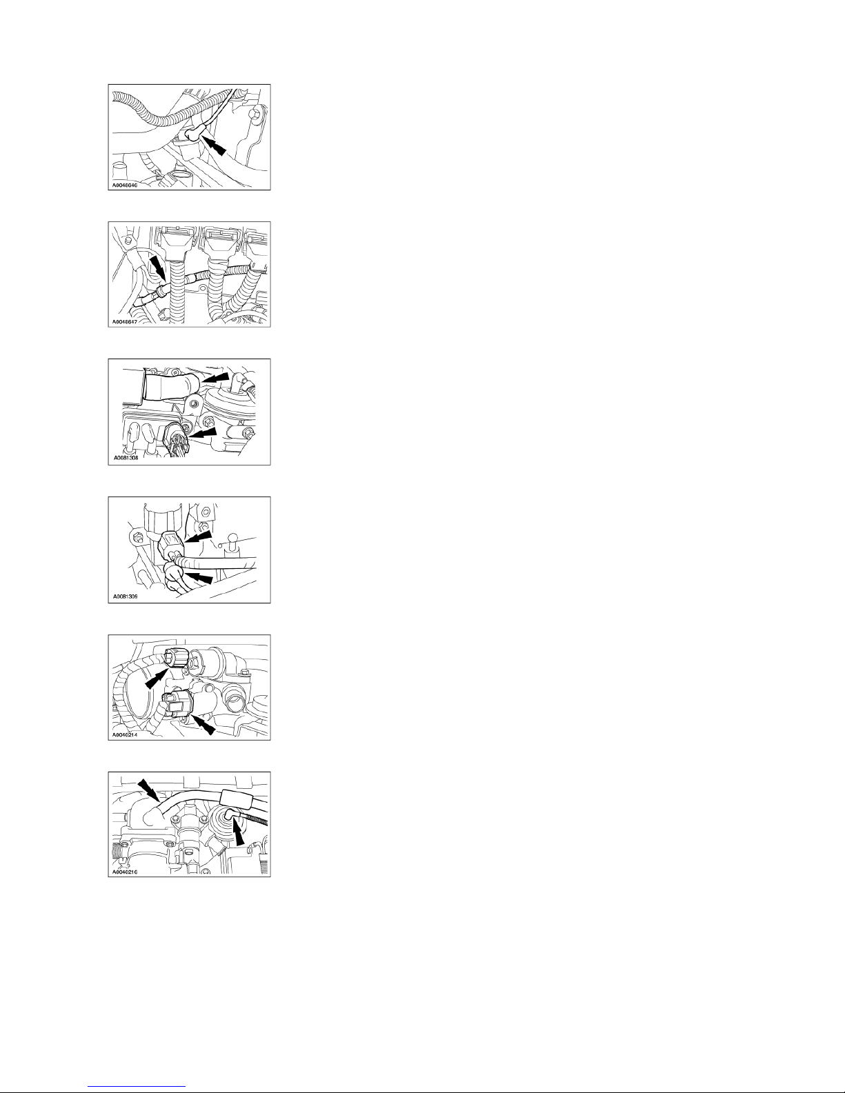
8. Disconnect the main vacuum harness.
9. Disconnect the fuel pulse damper vacuum hose.
Page 2
12
2004 Expedition/Navigator Workshop Manual
11/3/2009
http://www.fordtechservice.dealerconnection.com/pubs/content/~WS4J/~MUS~LEN/20/S
...
10. Disconnect the climate control vacuum hose.
11. Remove the idle air control (IAC) fresh air hose and disconne ct the differential pressure feedba ck exhaust gas recirculation (EGR) sensor electrical connector.
12. Disconnect the EGR vacuum regulator solenoid connections.
13. Disconnect the IAC and throt tle position (TP) sensor electrica l connectors.
14. Disconnect the EGR valve v acuum hose and the evaporative emission canister purge valve hose and position them aside.
15. Disconnect the evaporative emission canister purge valve vacu um hose and remove the vacuu m harness.
Page 3
12
2004 Expedition/Navigator Workshop Manual
11/3/2009
http://www.fordtechservice.dealerconnection.com/pubs/content/~WS4J/~MUS~LEN/20/S
...
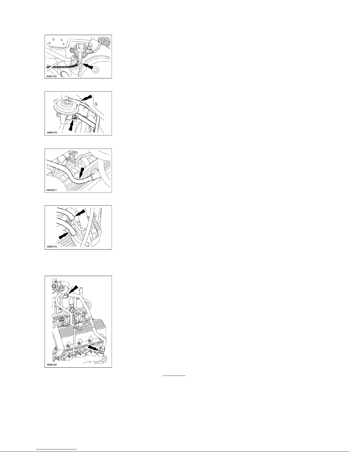
16. Remove the nut and disconnect the brake booster vacuum tube. Position the bracket and tube aside.
17. Position the crankcase ventilation hose aside.
18. Disconnect the differential pressure feedback EGR sensor vacuum hoses from the EGR tube .
19. Position the exhaust manifo ld to EGR valve tube aside.
Disconnect the upper fitting.
Loosen the lower fitting.
Position the tube aside.
20. Disconnect the fuel hose sp ring lock coupling. For additional information, refer to Section 310-00.
21. Disconnect the heater hose and the heated throttle body ho se.
Page 4

12
2004 Expedition/Navigator Workshop Manual
11/3/2009
http://www.fordtechservice.dealerconnection.com/pubs/content/~WS4J/~MUS~LEN/20/S
...
22. Disconnect the positive crankcase ventilation (PCV) hose.
23. Remove the four bolts and move the throttle body adapter forward slightly.
24. Disconnect the heated throttle body hose and remove the throttle body adapter.
Discard the throttle body adapter-to-intake manifold gasket.
Inspect the throttle body and ad apter for damage.
25. Remove the power steering reservoir upper mounting bracke t.
26. Disconnect and remove the eight ignition coils. For additional information, refer to Section 30 3-07A.
27. Disconnect the eight fuel injectors.
28. Rotate the belt tensioner clo ckwise and detach the drive belt from the generator pulley.
Page 5

12
2004 Expedition/Navigator Workshop Manual
11/3/2009
http://www.fordtechservice.dealerconnection.com/pubs/content/~WS4J/~MUS~LEN/20/S
...
29. Loosen the generator lower mounting bolts.
30. Disconnect the harness rout ing clip.
31. Remove the bolts and position the generator aside.
32. Remove the bolts, water thermostat housing and thermostat.
Discard the O-ring seal.
33. Remove the nine bolts.
Page 6

34. Remove the intake manifold assembly.
12
2004 Expedition/Navigator Workshop Manual
11/3/2009
http://www.fordtechservice.dealerconnection.com/pubs/content/~WS4J/~MUS~LEN/20/S
...
1. Lift the intake manifold.
2. Disconnect the intake manifold tuning valve connector.
3. Remove the intake manifold and discard the gaskets.
Inspect the intake manifold assembly for damage.
Installation
1. CAUTION: Do not use metal scrapers, power abrasive discs or any abrasive means to clean the sealing surfaces. These tools cause scratches and gouges that
make leak paths. Use a plasti c scraper only.
Clean all the sealing surfaces.
2. Install the upper intake manifold.
1. Position the new intake manifold gaskets.
2. Position the upper intake manifold.
3. Loosely install nine bolts.
3. Connect the intake manifold tuning valve electrical connector.
4. Install the water thermostat.
1. Install the thermostat.
2. Install a new O-ring seal.
Page 7

12
2004 Expedition/Navigator Workshop Manual
11/3/2009
http://www.fordtechservice.dealerconnection.com/pubs/content/~WS4J/~MUS~LEN/20/S
...
5. NOTE: The thermostat housing bolts are tightened in sequence with the intake manifold bolts.
Install the thermostat housing and loosely install the bolts.
6. Tighten the 11 bolts in two stages in the sequence shown.
Stage 1: tighten to 2 Nm (18 lb-in).
Stage 2: tighten to 25 Nm (18 lb-ft).
7. Position the generator and tighten the lower mounting bolts.
8. Install the generator upper mounting bracket bolts.
9. Install the harness routing clip.
Page 8

12
2004 Expedition/Navigator Workshop Manual
11/3/2009
http://www.fordtechservice.dealerconnection.com/pubs/content/~WS4J/~MUS~LEN/20/S
...
10. Rotate the belt tensioner clo ckwise and install the drive belt. Refer to the decal on the radiator upper air deflector for belt rout ing.
11. Connect the eight fuel injector electrical connectors.
12. Install and connect eight igni tion coils. For additional information, refer to Section 303-07A.
13. Connect the fuel hose spring lock coupling. For additional information, refer to Section 310-00.
14. Install the power steering reservoir upper mounting bracket.
15. Roughly position the throttle body adapter in the vehicle and connect the heated throttle body hose.
16. Install the throttle body adapter.
Install a new throttle body adapter gasket.
Position the throttle body adap ter and install the bolts in two stages.
Stage 1: Tighten to 90 Nm (80 lb-in).
Stage 2: Tighten an additional 90 degrees.
17. Connect the PCV hose.
Page 9

12
2004 Expedition/Navigator Workshop Manual
11/3/2009
http://www.fordtechservice.dealerconnection.com/pubs/content/~WS4J/~MUS~LEN/20/S
...
18. Connect the heater hose and heated throttle body hose.
19. Install the exhaust manifold to EGR valve tube.
Hand-tighten the fittings.
Tighten the upper fitting.
Tighten the lower fitting.
20. Connect the differential pressure feedback EGR sensor vacuum hoses to the EGR tube.
21. Connect the brake booster vacuum tube and bracket, and install the nut.
22. Roughly position the vacuum harness and connect the evaporative emission canister purge v alve vacuum hose.
Page 10

12
2004 Expedition/Navigator Workshop Manual
11/3/2009
http://www.fordtechservice.dealerconnection.com/pubs/content/~WS4J/~MUS~LEN/20/S
...
23. Connect the evaporative emission canister purge valve hose and the EGR valve vacuum hose.
24. Connect the TP sensor and IAC electrical connectors.
25. Connect the EGR vacuum regulator solenoid connections.
26. Install the IAC fresh air hose and connect the differential pressure feedback EGR sensor elect rical connector.
27. Connect the climate control vacuum hose.
28. Connect the fuel pulse damper vacuum hose.
Page 11

12
2004 Expedition/Navigator Workshop Manual
11/3/2009
http://www.fordtechservice.dealerconnection.com/pubs/content/~WS4J/~MUS~LEN/20/S
...
29. Connect the main vacuum harness.
30. Install the accelerator cable bracket and the bolts.
31. Connect the throttle body cam .
1. Connect the accelerator cable.
2. Connect the speed control ac tuator cable.
3. Install the throttle return spring.
32. Install the appearance cover mounting bracket and the three bolts.
33. Connect the upper radiator hose and position the clamp.
34. Install the air cleaner outlet pipe. For additional information, refer to Section 303-12.
35. Connect the battery ground cable. For additional information, refer to Section 414-01.
36. Fill and bleed the engine coo ling system. For additional inform ation, refer to Section 303-03.
Page 12

12
2004 Expedition/Navigator Workshop Manual
11/3/2009
http://www.fordtechservice.dealerconnection.com/pubs/content/~WS4J/~MUS~LEN/20/S
...
 Loading...