

Page 1

2007 PCED On Board Diagnostics Introduction
Procedure revision date: 03/29/2006
Acronyms and Definitions
This acronyms and definitions listing contains technical terms applicable to Ford Motor Company
Note:
products. It is not intended to be an all-inclusive dictionary of components and their functions. If a detailed
description of a particular system or component is desired, refer to the applicable section within this PC/ED
Manual or refer to the Workshop Manual for the specific vehicle being repaired.
2V: Two valves per engine cylinder
3V: Three valves per engine cylinder
4V: Four valves per engine cylinder
A/C: Air Conditioning
A/CC: Air Conditioning Clutch
A/CCR: Air Conditioning Clutch Control Relay
ACCS: Air Conditioning Cycling Switch
ACDS: Air Conditioning Diagnostic Switch (refrigerant containment switch)
ACET: Air Conditioning Evaporator Temperature
ACP: Air Conditioning Head Pressure or A/C cycling switch input state
ACPSW: Air Conditioning Pressure Switch
ACPT: Air Conditioning Pressure Transducer (Switch)
A/D: Analog-to-Digital. Analog-to-Digital signal conversion.
AFCM: Alternative Fuel Control Module
AIR: Secondary Air Injection
AIR EVAL: Air System Evaluated. Displays a YES or NO status indicating whether the AIR System
has been evaluated for On Board Diagnostic (OBD) purposes.
AIRM: Secondary Air Pump Monitor
APP: Accelerator Pedal Position
ARB: Air Resource Board
ASCII: American Standard Code Information Interchange
ATDC: After Top Dead Center. The location of the piston after it has reached the top of its stroke.
Measured in degrees of crankshaft rotation.
BARO: Barometric Pressure
BJB: Battery Junction Box
BPA: Brake Pedal Applied
BPP: Brake Pedal Position
BPS: Brake Pedal Switch/Speed Control Deactivation
BTDC: Before Top Dead Center. The location of the piston before it has reached the top of its stroke.
Measured in degrees of crankshaft rotation.
CAC: Charge Air Cooler. A device which lowers the temperature of pressurized intake air.
Page 2

CAFE: Corporate Average Fuel Economy. A set of federal requirements and regulations which
govern fuel economy standards.
CAN: Controller Area Network
CCM: Comprehensive Component Monitor
CD A through J: Coil Driver 1 through 10
CGND: Case Ground. Provides a ground source for the PCM case.
CHT: Cylinder Head Temperature
CHTIL: Cylinder Head Temperature Indicator Lamp
CKP: Crankshaft Position
CL: Closed Loop. An operating condition or mode which enables operation based on sensor
feedback.
CMP, CMP1, CMP2: Camshaft Position. CMP1 and CMP2 on V engines where applicable.
CMS: Catalyst Monitor Sensor. The downstream HO2S.
CMVSS: Canadian Motor Vehicle Safety Standards
CO: Carbon Monoxide. A colorless, odorless, and toxic gas that is a component of auto exhaust
emissions.
CO 2 : Carbon Dioxide. A colorless, odorless gas that is a normal by-product of the combustion of
fuel.
CONT: Continuous Memory. The portion of keep alive memory (KAM) used to store DTCs generated
during the continuous memory self-test.
COP: Coil On Plug. Ignition coil on plug assembly.
CPP: Clutch Pedal Position
CT: Closed Throttle. A mode in which the PCM varies the pulse width of the fuel injectors to obtain
the air/fuel mixture appropriate for closed throttle operation.
CTO: Clean Tach Output. Signal used to drive the instrument panel tachometer.
CV: Canister Vent Solenoid. A solenoid which seals the evaporative emission (EVAP) system from
the atmosphere during the EVAP monitor test.
DC: 1. Direct Current. Electric current flowing in one direction. 2. Duty Cycle. The voltage
measurement of ON time versus the full cycle period, expressed in percent.
DCL: Data Communication Link. A communication path between various in-vehicle electronic
modules.
DI: Distributor Ignition. A system in which the ignition coil secondary circuit is sequenced by a
distributor.
DIS: Distributorless Ignition System. A system in which the ignition coil secondary circuit is
sequenced without a distributor.
DLC: Data Link Connector. SAE standard J1962 connector providing access to vehicle diagnostic
information.
DMM: Digital Multimeter
DOHC: Dual Overhead Cam. An engine configuration that uses 2 camshafts positioned above the
valves.
DOL: Data Output Line. A circuit that sends certain information from the PCM to the instrument
cluster.
DPFE: Differential Pressure Feedback EGR. A system that uses a pressure transducer to control the
Page 3

operation of the exhaust gas recirculation (EGR) vacuum regulator solenoid.
DTM: Diagnostic Test Mode. A level of capability in an OBD system.
DTC: Diagnostic Trouble Code. An alpha/numeric identifier for a concern identified by the OBD
system.
E-85: Fuel containing 85% ethanol alcohol
ECT: Engine Coolant Temperature
ECU: Electronic Control Unit. A module that handles the control strategy and monitors system inputs
or outputs.
EEC: Electronic Engine Control
EEGR: Electric Exhaust Gas Recirculation System
EEPROM: Electrically Erasable Programmable Read-Only Memory. An electronic component in the
PCM that allows the electronic storage of information.
EGR: Exhaust Gas Recirculation. A process in which a small amount of exhaust gas is routed into the
combustion chamber.
EGRMC (1-4): Electric Exhaust Gas Recirculation Motor Control
EGRT: Exhaust Gas Recirculation Valve Temperature. A temperature sensor that is threaded into the
bottom of the intake plenum.
EI: Integrated Electronic Ignition. An electronic ignition system that has the ignition control module
(ICM) integrated into the PCM.
EI-HDR: Electronic Ignition-High Data Rate. Formerly known as Electronic Distributorless Ignition
System.
EMI: Electromagnetic Interference. Usually caused by ignition voltage spikes, solenoids, relay
operation, or noisy generator contacts.
EOL: End of Line. A system designed specifically for use at assembly plants to make sure all new
vehicles conform to design specifications.
EONV: Engine Off Natural Vacuum
EOT: Engine Oil Temperature
EPA: Environmental Protection Agency
E-Quizzer: Enhanced Quizzer
ESM: EGR System Module
ESOF: Electronic Shift-on-the-Fly
ETB: Electronic Throttle Body
ETC: Electronic Throttle Control
ETCREF: Voltage Reference (5V) for ETC (APP VREF, TP VREF).
EVAP: Evaporative Emissions. A system to prevent fuel vapor from escaping into the atmosphere.
EVAPCP: Evaporative Canister Purge Solenoid. A solenoid which controls the venting of fuel vapor
from the evaporative emissions canister into the intake manifold for combustion.
EVO: Electronic Variable Orifice
FCIL: Fuel Cap Indicator Lamp. Indicates that the fuel filler cap is not correctly installed.
FEAD: Front End Accessory Drive
FEPS: Flash EEPROM Programming Signal. An 18-volt DC signal input from the scan tool used by
the PCM to initiate programming.
FFV: Flexible Fuel Vehicle
Page 4

FLI: Fuel Level Input. Provides information on the amount of liquid fuel in the fuel tank. Used by the
EVAP monitor to calculate the fuel tank vapor volume. Displayed as a percentage.
FMEM: Failure Mode Effects Management. Operating strategy that maintains limited vehicle function
in the event of a PCM or EEC component failure.
FP: 1. Fuel Pump. Indicates whether the pump has been commanded ON or OFF by the PCM. 2.
Fuel Pump (Modulated). Fuel pump duty cycle percentage.
FPDM: Fuel Pump Driver Module. A module that controls the electric fuel pump.
FRP: Fuel Rail Pressure
FRPT: Fuel Rail Pressure Temperature
FSS: Fan Speed Sensor
FTP: Fuel Tank Pressure
FUEL PR: Fuel Pressure. Measurement of the force of the fuel delivered by the fuel pump.
FUELPW: Fuel Pulse Width. Displays the commanded pulse width at the time of the last data update.
FUELPW1: Fuel Injector Pulse Width #1. Corresponds to injectors normally affected by HO2S11.
FUELPW2: Fuel Injector Pulse Width #2. Corresponds to injectors normally affected by HO2S21.
FUELSYS: Fuel System Status (OPEN/CLOSED Loop). Formerly known as LOOP.
FWD: Front Wheel Drive
GND: Ground
GPM: 1. Grams per Mile. 2. Gallons per Minute.
GVW: Gross Vehicle Weight
GVWR: Gross Vehicle Weight Rating
HC: 1. Hydrocarbon. A by-product of combustion and a component of auto exhaust emissions. 2.
High Compression.
HLOS: Hardware Limited Operating Strategy. A mode of operation where the PCM uses fixed values
in response to internal PCM concerns in place of output commands.
HO: High Output
HO2S: Heated Oxygen Sensor. Provides information on rich or lean exhaust conditions to the PCM.
HTR11, HTR12, HTR13, HTR21, HTR22: HO2S Heater. Heater element for the HO2S sensor.
Hz: Hertz. Cycles per second.
IAC: Idle Air Control. Electrical control of throttle bypass air.
IAT: Intake Air Temperature
IAT2: Intake Air Temperature 2. Used on supercharged vehicles.
IC: Integrated Circuit. A small semi-conductor device capable of many separate circuit functions.
IFS: Inertia Fuel Switch
IMRC: Intake Manifold Runner Control. Controls or modifies airflow in the intake air system.
IMRCM: Intake Manifold Runner Control Monitor. Monitors the IMRC circuits for concerns.
IMTV, IMTV1, IMTV2: Intake Manifold Tuning Valve. Controls airflow through runners in a split intake
manifold.
INJ1, INJ2, INJ3, INJ4, INJ5, INJ6, INJ7, INJ8, INJ9, INJ10: Injector number or its signal output from
the PCM.
IPC: Independent Plausibility Checker
ISO: International Standards Organization
Page 5

KAM: Keep Alive Memory. A portion of the memory within the PCM that must have power even when
the vehicle is not operating.
KAPWR: Keep Alive Power. A dedicated and unswitched power circuit that maintains KAM.
KOEO Self-Test: Key On Engine Off self-test. A test of the EEC system conducted by the PCM with
power applied and the engine at rest.
KOER Self-Test: Key On Engine Running self-test. A test of the EEC system conducted by the PCM
with the engine running and the vehicle at rest.
Km/h: Kilometers per Hour
kPa: Kilopascal. Unit of pressure. 3.386 kPa equals 1 (in-Hg).
L: Liters. The unit of volume in the metric measuring system. One liter equals 1.06 quarts.
LEV: Low Emissions Vehicle
LONGFT: Long-Term Fuel Trim. Fuel flow adjustment determined by the PCM.
M-85: Fuel containing 85% methanol alcohol
MAF: Mass Air Flow
MAP: Manifold Absolute Pressure. The internal pressure of the intake manifold.
MFI: Multiport Fuel Injection. A fuel-delivery system in which each cylinder is individually fueled.
MIL: Malfunction Indicator Lamp. An indicator lamp alerting the driver of an emission related concern.
MISF: Misfire. Any event in the cylinder that causes a sudden change in acceleration of the
crankshaft.
MON: Motor Octane Number
MSOF: Manual Shift-on-the-Fly
MY: Model Year
NA: Naturally Aspirated. An engine that is not supercharged or turbocharged.
NC: Normally Closed
NGS: New Generation Self-Test Automatic Readout (STAR) tester
NO: Normally Open
NO X : Oxides of Nitrogen. Gasses formed at high combustion temperatures.
OASIS: On-line Automotive Service Information System
OBD, OBD-II: On Board Diagnostics, On Board Diagnostics Second Generation. A system that
monitors the PCM input and output control signals.
OCT ADJ: Octane Adjust. Compensating strategy that adjusts for changes in fuel octane.
OEM: Original Equipment Manufacturer
OHC: Overhead Cam. An engine configuration that uses a single camshaft positioned above the
valves.
OL: Open Loop. An operating condition based on instructions not modified by PCM feedback.
ORVR: On-Board Refueling Vapor Recovery
OSC: Output State Control
OSS: Output Shaft Speed
OTM: Output Test Mode
PATS: Passive Anti-Theft System
PCM: Powertrain Control Module. Formerly known as the electronic engine control (EEC) processor.
PCV: Positive Crankcase Ventilation. A system which allows the controlled flow of crankcase vapors
Page 6

into the combustion chamber.
PID: Parameter Identifier. Identifies an address in the PCM memory which contains operating
information.
PIP: Profile Ignition Pickup. Provides crankshaft position information for ignition synchronization.
PPM: Parts per Million. A measure used in emission analysis.
PROM: Programmable Read-Only Memory. Similar to ROM, except without program instructions.
PSP: Power Steering Pressure. Indicates the pressure in the power steering system.
PSPT: Power Steering Pressure Transducer
PTO: Power Take-Off
PW: Pulse Width. The length of time an actuator, such as a fuel injector, remains energized.
PWM: Pulse Width Modulation. Controls the intensity of an output by varying the signal duty cycle.
PWR GND: Power Ground. The main ground circuit in the EEC system.
RAM: Random Access Memory. Memory into which information can be written as well as read.
RF: Radio Frequency
RFI: Radio Frequency Interference
RFS: Returnless Fuel System
ROM: Read-Only Memory. Computer memory that can be accessed and used, but not altered.
RPM: Revolutions Per Minute
RTN: Return. A dedicated sensor ground circuit.
RWD: Rear Wheel Drive
SAE: Society of Automotive Engineers
SCB: Supercharger Bypass
SCBC: Supercharger Bypass Control. A system that allows manifold vacuum to be bled away from
the supercharger wastegate actuator to allow for maximum boost.
SFI: Sequential Multiport Fuel Injection. A multiport fuel delivery system in which each injector is
individually energized and timed relative to its cylinder intake event.
SHRTFT: Short-Term Fuel Trim. Fuel flow adjustment in response to the HO2S sensor(s) input during
closed-loop operation.
SIG RTN: Signal Return. A dedicated sensor ground circuit that is common to 2 or more sensors.
SOHC: Single Overhead Cam
TA: Traction Assist
TAC: Throttle Actuator Control
TACM, TACMP, TACMN, TACP (+/-): Throttle Actuator Control Motor +/- used in the ETC system.
TB: Throttle Body. A device that controls airflow through the engine via a butterfly valve and has an
air bypass channel around the throttle plate.
TC: 1. Traction Control. Combines anti-lock braking and axle torque reduction to control wheel
slippage. 2. Turbocharger.
TDC: Top Dead Center
TP: Throttle Position sensor. A potentiometer that provides throttle angle and rate information for the
PCM.
TP1: Throttle Position 1
TP2: Throttle Position 2
Page 7

TSB: Technical Service Bulletin. Notifies technician of any known vehicle concerns, procedures, or
general repair information.
VCT, VCT1, VCT2: Variable Camshaft Timing. VCT1 and VCT2 on V engines where applicable.
VECI: Vehicle Emission Control Information
VIN: Vehicle Identification Number. A unique identification number given to every vehicle produced.
Includes information about the year, model, engine, and plant origin of the vehicle.
VMV: Vapor Management Valve. Also known as EVAPCP. Refer to EVAPCP.
VBPWR: Vehicle Buffered Power. A PCM-supplied power source that supplies regulated voltage.
VPWR: Vehicle Power. A switched circuit that provides power to the EEC system. Compare to battery
voltage (B+).
VREF: Reference Voltage. A dedicated circuit that provides an approximately 5.0 volt signal used as
a reference by certain sensors.
WOT: Wide Open Throttle. A condition of maximum airflow through the throttle body.
Transmissions:
The automatic transmission naming convention is as follows:
Note:
The first character, a number, is the number of forward gears.
!
The second character, either the letter F or R, represents front (transaxle) or rear
!
(transmission) wheel drive.
The next set of characters, a grouping of numbers, represents the design torque capacity of
!
the transmission/transaxle.
! The last character, if used, is one of the following:
E for electronic shift
!
N for non-synchronous shift
!
S for synchronous shift
!
W for wide ratio
!
As an example, for the 4F27E transaxle, the number of forward gears is 4, the character F indicates
front transaxle, 27 represents 270 ft-lbs of torque capacity and the character E represents an
electronic shift.
A/T: Automatic Transmission
CCS: Coast Clutch Solenoid
EPC, EPC1, EPC2: Electronic Pressure Control
ESS: Electronic Shift Scheduling
ISS: Intermediate/Input Shaft Speed Sensor
M/T: Manual Transmission/Transaxle
OCS: Overdrive Cancel Switch
OSS: Output Shaft Speed. Indicates the rotational speed of the transmission output shaft.
PNP: Park/Neutral Position switch.
REVERSE or REV: Transmission Reverse Switch Input
SSA/SSB/SSC/SSD/SSE: Shift solenoids. Devices in an automatic transmission that control the
shifting by varying fluid flow when commanded by the PCM.
Page 8

SS1/SS2/SS3: Shift solenoids. Devices in an automatic transmission that control the shifting by
varying fluid flow when commanded by the PCM.
TCC/TCCH: Torque Converter Clutch. When energized, causes a mechanical engagement and
disengagement of the torque converter clutch.
TCIL: Transmission Control Indicator Lamp. Indicates that the TCS has been activated.
TCS: Transmission Control Switch. Modifies the operation of electronically controlled transmissions.
TFT: Transmission Fluid Temperature. Indicates the temperature of transmission fluid.
TR, TR1, TR2, TR3, TR4: Transmission Range. The range in which the transmission is operating.
TSS: Turbine Shaft Speed. Indicates the rotational speed of the transmission turbine shaft.
VSS: Vehicle Speed Sensor. A magnetic pickup device that generates an AC signal that is
proportional to the vehicle speed.
VSOUT: Vehicle Speed Output. A pulse width modulated vehicle speed signal.
Page 9

2007 PCED On Board Diagnostics Introduction
Procedure revision date: 03/29/2006
Introduction
The descriptions and specifications contained in this manual were in effect at the time this manual
Note:
was approved for publication. Ford Motor Company reserves the right to discontinue models at any time, or
change specifications or design without notice and without incurring obligation.
Important Safety Notice
Appropriate repair methods and procedures are essential for the safe, reliable operation of all motor
vehicles, as well as the personal safety of the individual doing the work. This manual provides general
directions for repairing vehicles with tested, effective techniques. Following them helps to establish reliability.
There are numerous variations in procedures, techniques, tools, and parts for repairing vehicles, as well as
in the skill of the individual doing the work. This manual cannot possibly anticipate all such variations and
provide advice or cautions as to each. Accordingly, anyone who departs from the instructions provided in
this manual must first establish that they compromise neither their personal safety nor the vehicle integrity
by their choice of methods, tools, or parts.
Notes, Cautions, and Warnings
As you read through the procedures, NOTES, CAUTIONS, and WARNINGS are found throughout the
publication. Each one is there for a specific purpose. NOTES give added information that help to complete a
particular procedure. CAUTIONS are given to prevent making errors that could damage the vehicle.
WARNINGS are to remind the technician to be especially careful in those areas where carelessness may
cause personal injury. The following list contains some general WARNINGS that should be followed when
working on a vehicle.
Always wear safety glasses for eye protection.
!
Use safety stands whenever a procedure requires working under the vehicle.
!
Make sure that the key is always in the OFF position, unless otherwise required by the procedure.
!
Set the parking brake when working on the vehicle. If the vehicle is equipped with an automatic
!
transmission, place the gear selector in PARK unless otherwise instructed for a specific operation. If
the vehicle is equipped with a manual transmission, the gear selector should be in REVERSE (engine
OFF) or NEUTRAL (engine ON) unless instructed otherwise for a specific operation. Place wood
blocks (4 inch x 4 inch or larger) against the front and rear surfaces of the tires to help prevent the
vehicle from moving.
Operate the engine in a well-ventilated area to avoid the danger of carbon monoxide poisoning.
!
Keep yourself and your clothing away from moving parts when the engine is running, especially the
!
drive belts.
Page 10

To prevent serious burns, avoid contact with hot metal parts such as the radiator, exhaust manifold
!
(s), tail pipe(s), three-way catalytic converter(s), and muffler(s).
Do not smoke while working on a vehicle.
!
To avoid injury, always remove rings, watches, loose hanging jewelry, and loose clothing before
!
beginning work on a vehicle.
When it is necessary to work under the hood, keep hands and other objects clear of the radiator fan
!
blades.
Preface
This manual provides a step-by-step approach for diagnosing driveability, emission, and powertrain control
system symptoms. Before beginning diagnosis, it may be helpful to reference any Technical Service
Bulletins (TSBs) or On-line Automotive Service Information System (OASIS) information when this is
available. TSB/OASIS information is available on either the Professional Technician Society (PTS) or
Motorcraft® website.
For the diesel engines, refer to the appropriate Diesel Powertrain Control/Emissions Diagnosis
Note:
Manual. For the Escape Hybrid or Mariner Hybrid, refer to the Escape Hybrid, Mariner Hybrid Powertrain
Control/Emissions Diagnosis Manual.
This manual is used in conjunction with the Workshop and Wiring Diagrams Manuals. The Workshop
Manuals are used to provide additional diagnostic or component removal and installation information. Refer
to the Wiring Diagrams Manuals for vehicle specific wiring information and component, connector, and splice
locations.
The following is a description of the information contained in each section of this manual.
Section 1: Description and Operation
This section contains description and operation information on powertrain control systems and components
and provides the technician with a general knowledge of the powertrain control system. Use this section
when general information about the powertrain control system is desired.
Section 2: Diagnostic Methods
This section contains information on specific diagnostic tasks that are used during diagnosis. Descriptions of
specific diagnostic methods are included, as well as detailed instructions on how to access or carry out the
task.
Section 3: Symptom Charts
All diagnosis begins in Section 3 with QT Step 1: Powertrain Control Module (PCM) Quick Test. If the PCM
Page 11

Quick Test is completed and no diagnostic trouble codes (DTCs) are retrieved, the technician is directed to
Step 2: No Diagnostic Trouble Codes (DTCs) Present Symptom Chart Index. The No Diagnostic Trouble
Codes (DTCs) Present Symptom Chart Index contains the list of symptoms addressed in this manual, and
directs the technician to the appropriate Step 3: No Diagnostic Trouble Codes (DTCs) Present Symptom
Chart. If no PCM DTCs are present and the vehicle symptom is not listed in Step 2: No Diagnostic Trouble
Codes (DTCs) Present Symptom Chart Index, the technician should go to the appropriate Workshop Manual
section to continue diagnosis.
Section 4: Powertrain Diagnostic Trouble Code (DTC) Charts and
Descriptions
This section contains the Diagnostic Trouble Code (DTC) Charts and Descriptions. These charts and
descriptions are referenced if a DTC is retrieved in Section 3 . Also included in this section are the list of
possible causes and diagnostic aids.
Section 5: Pinpoint Tests
All pinpoint tests are included in this section. Never enter a pinpoint test unless directed there. When
directed to a pinpoint test, always read the information included at the beginning of the pinpoint test.
Section 6: Reference Values
This section contains the Typical Diagnostic Reference Values charts. The technician is directed to these
charts from Pinpoint Test Z in Section 5 .
How to Use the Diagnostic Procedures
Use the information about the vehicle driveability or emission concerns to attempt to verify/recreate
!
the symptom. Look for any vehicle modifications or aftermarket items that may contribute to the
symptom. A check of any applicable TSBs or OASIS messages may be useful if this information is
available.
Go to Section 3 , QT Step 1: Powertrain Control Module (PCM) Quick Test. Carry out the PCM quick
!
test steps. Follow any notes as directed.
If the PCM quick test is completed, no DTCs were retrieved, and no special notes applied, go to Step
!
2: No Diagnostic Trouble Codes (DTCs) Present Symptom Chart Index.
Select the symptom that best describes the vehicle symptom (for multiple symptoms select the one
!
that is most evident). Go to Step 3: No Diagnostic Trouble Codes (DTCs) Present Symptom Chart
that is indicated. If no PCM DTCs are present and the vehicle symptom is not listed in the No
Diagnostic Trouble Codes (DTCs) Present Symptom Chart Index, go to the appropriate Workshop
Manual section to continue diagnosis.
The No Diagnostic Trouble Codes (DTCs) Present Symptom Charts contain areas to be tested for
!
diagnosis of the vehicle symptom. The chart is arranged to place the higher probability or easiest to
test items toward the top of the chart. However, the technician is not required to follow this order due
Page 12

to reasons such as variations in vehicle type, vehicle repair history, or technician experience.
Deleted Vehicles:
The System/Component column indicates the areas that are tested. This column may also
"
contain a quick system/component test.
The Reference column indicates where to go for the System/Component testing. All references
"
are to the beginning of a pinpoint test in Section 5 of this manual unless noted otherwise. If
referred to a pinpoint test in this manual or a Workshop Manual section, go to the procedures.
Follow the directions given in those procedures, including directions to other tests or sections.
If a damaged part is found, repair as directed. If no concern is found, and diagnosis in that
area is complete, return to the No Diagnostic Trouble Codes (DTCs) Present Symptom Chart
and continue to the next item.
If a quick system/component test is in the System/Component column, the Reference column
"
indicates where to go if the test failed.
During diagnosis, if directed to test a system/component that is not contained on that vehicle, go to
!
the next step.
If the No Diagnostic Trouble Codes (DTCs) Present Symptom Chart for the vehicle symptom is
!
completed and no concern is found, return to Step 2: No Diagnostic Trouble Codes (DTCs) Present
Symptom Chart Index to address the next most prominent symptom. If all diagnosis is complete and
no concern is found, it may be helpful to GO to Pinpoint Test Z in Section 5 to continue diagnosis.
The installation of any new component that affects the PCM adaptive learning strategies (idle speed,
!
refueling event, or fuel trim) requires the reset of keep alive memory (KAM). Refer to Section 2,
Resetting The Keep Alive Memory (KAM) .
After any repair, reconnect any components and remove any test equipment. Verify that the vehicle is
!
operating correctly and the original complaint is no longer present. If a DTC was present, clear the
DTCs and repeat the self-test to verify the repair.
If a symptom is determined to be intermittent, a careful visual and physical underhood inspection of
!
connectors, wiring harnesses, vacuum lines, and components is required. The Customer Information
Worksheet may contain more detailed symptom information. Before an in-depth diagnosis begins,
start the engine and wiggle wires, tap on components while listening for an indication of a concern
(such as an RPM change or a relay clicking).
Information about engine conditions is stored when a DTC that illuminates the malfunction indicator lamp
(MIL) is set. This information is called freeze frame data and may be helpful in diagnosing intermittent
concerns. Refer to Section 2, Freeze Frame Data for more information.
What's New in this Manual
The following is a list of changes to this manual for 2007:
New Vehicles:
Explorer Sport Trac
!
Page 13

Ford GT
!
Lincoln LS
!
Other Changes:
Computer-controlled shutdown feature for equipped vehicles
!
Crown Victoria, Grand Marquis, Town Car and Ranger equipped with new 170-pin PCM
!
Mustang with new 5.4L supercharged engine
!
Page 14

2007 PCED On Board Diagnostics SECTION 1: Description and Operation
Procedure revision date: 03/29/2006
Catalyst and Exhaust Systems
Overview
The catalytic converter and exhaust systems work together to control the release of harmful engine exhaust
emissions into the atmosphere. The engine exhaust gas consists mainly of nitrogen (N), carbon dioxide (CO
) and water vapor (H 2 O). However, it also contains carbon monoxide (CO), oxides of nitrogen (NO x ),
2
hydrogen (H), and various unburned hydrocarbons (HCs). The major air pollutants of CO, NO x , and HCs,
and their emission into the atmosphere must be controlled.
The exhaust system generally consists of an exhaust manifold, front exhaust pipe, front heated oxygen
sensor (HO2S), rear exhaust pipe, catalyst HO2S, a muffler, and an exhaust tailpipe. The catalytic converter
is typically installed between the front and rear exhaust pipes. On some vehicle applications, more than one
catalyst is used between the front and rear exhaust pipes. Catalytic converter efficiency is monitored by the
on board diagnostic (OBD) system strategy in the PCM. For information on the OBD catalyst monitor, refer
to the description for the Catalyst Efficiency Monitor in this section.
The number of HO2Ss used in the exhaust stream and the location of these sensors depend on the vehicle
emission certification level (LEV, LEV-II, ULEV, PZEV). On most vehicles only 2 HO2Ss are used in an
exhaust stream. The front sensors (HO2S11/HO2S21) before the catalyst are used for primary fuel control
while the ones after the catalyst (HO2S12/HO2S22) are used to monitor catalyst efficiency. However, some
partial zero emission vehicles (PZEV) use 3 HO2Ss for each engine bank. The stream 1 sensors
(HO2S11/HO2S21) located before the catalyst are used for primary fuel control, the stream 2 sensors
(HO2S12/HO2S22) are used to monitor the light-off catalyst, and the stream 3 sensors (HO2S13/HO2S23)
located after the catalyst are used for long term fuel trim control to optimize catalyst efficiency (fore aft
oxygen sensor control). Current PZEV vehicles use only a 4-cylinder engine, so only the bank 1 HO2Ss are
used.
Page 15
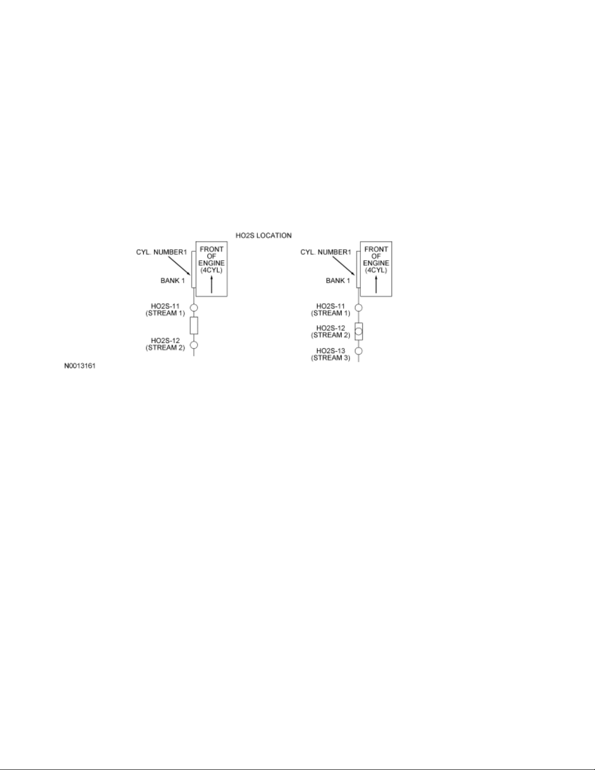
V-Engines
In-Line Engines
Catalytic Converter
A catalyst is a material that remains unchanged when it initiates and increases the speed of a chemical
reaction. A catalyst also enables a chemical reaction to occur at a lower temperature. The concentration of
exhaust gas products released to the atmosphere must be controlled. The catalytic converter assists in this
task. It contains a catalyst in the form of a specially treated ceramic honeycomb structure saturated with
catalytically active precious metals. As the exhaust gases come in contact with the catalyst, they are
changed into mostly harmless products. The catalyst initiates and speeds up heat producing chemical
reactions of the exhaust gas components so they are used up as much as possible.
Light Off Catalyst
As the catalyst heats up, converter efficiency rises rapidly. The point at which conversion efficiency exceeds
50% is called catalyst light off. For most catalysts this point occurs at 246°C to 302°C (475°F to 575°F ) . A
fast light catalyst is a 3-way catalyst (TWC) that is located as close to the exhaust manifold as possible.
Because the light off catalyst is located close to the exhaust manifold it lights off faster and reduces
emissions more quickly than the catalyst located under the body. Once the catalyst lights off, the catalyst
quickly reaches the maximum conversion efficiency for that catalyst.
Three-Way Catalyst (TWC) Conversion Efficiency
A TWC requires a stoichiometric fuel ratio, 14.7 pounds of air to 1 pound of fuel (14.7:1), for high conversion
efficiency. In order to achieve these high efficiencies, the air/fuel ratio must be tightly controlled with a
narrow window of stoichiometry. Deviations outside of this window greatly decrease the conversion
efficiency. For example a rich mixture decreases the HC and CO conversion efficiency while a lean mixture
decreases the NO x conversion efficiency.
Page 16
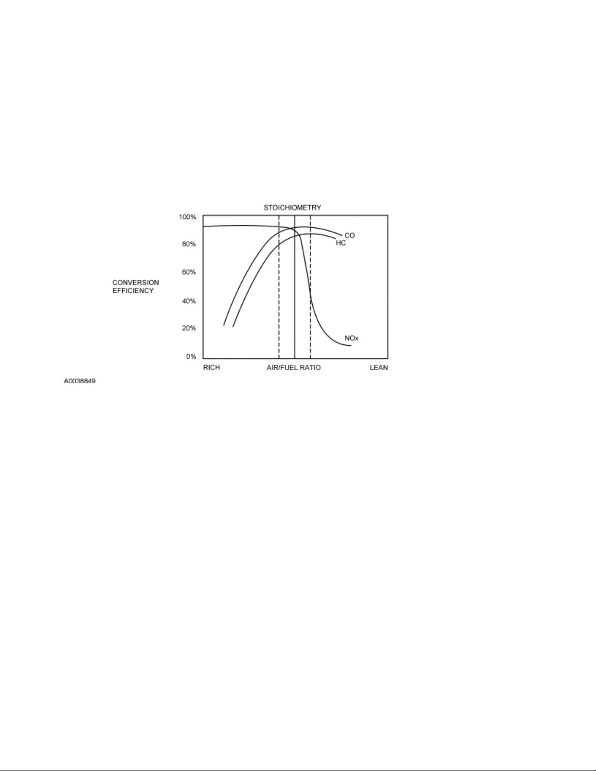
TWC Conversion Efficiency Chart
Exhaust System
The purpose of the exhaust system is to convey engine emissions from the exhaust manifold to the
atmosphere. Engine exhaust emissions are directed from the engine exhaust manifold to the catalytic
converter through the front exhaust pipe. A HO2S is mounted on the front exhaust pipe before the catalyst.
The catalytic converter reduces the concentration of CO, unburned HCs, and NO x in the exhaust emissions
to an acceptable level. The reduced exhaust emissions are directed from the catalytic converter past
another HO2S mounted in the rear exhaust pipe and then on into the muffler. Finally, the exhaust emissions
are directed to the atmosphere through an exhaust tailpipe.
On some PZEV, there is a total of 3 HO2S in the exhaust stream. One near the exhaust manifold (stream 1),
one in the middle of the light-off catalyst (stream 2), and the third (stream 3) is mounted after the light-off
catalyst.
Page 17
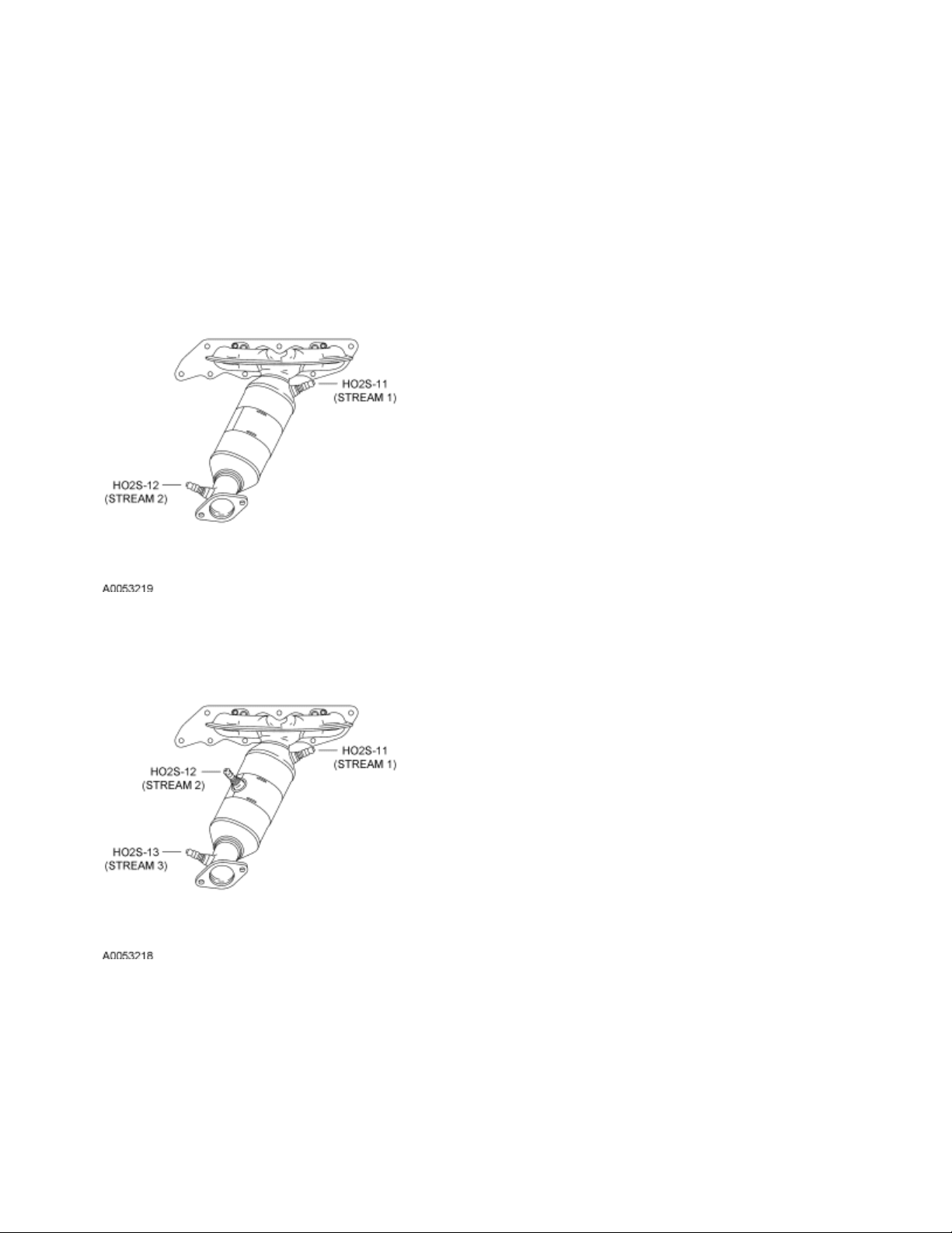
Typical Bank 1 Catalyst 2 HO2S Configuration
Typical Bank 1 Catalyst 3 HO2S Configuration
Underbody Catalyst
The underbody catalyst is located after the light off catalyst. The underbody catalyst may be in line with the
light off catalyst, or the underbody catalyst may be common to 2 light off catalysts, forming a Y pipe
configuration. For an exact configuration of the catalyst and exhaust system for a specific vehicle, refer to
the Workshop Manual Section 309-00, Exhaust System.
Page 18

Three-Way Catalytic (TWC) Converter
The TWC converter contains either platinum (Pt) and rhodium (Rh) or palladium (Pd) and rhodium (Rh). The
TWC converter catalyzes the oxidation reactions of unburned HCs and CO and the reduction reaction of NO
. The 3-way conversion can be best accomplished by always operating the engine air fuel/ratio at or close
x
to stoichiometry.
Exhaust Manifold Runners
The exhaust manifold runners collect exhaust gases from engine cylinders. The number of exhaust
manifolds and exhaust manifold runners depends on the engine configuration and number of cylinders.
Exhaust Pipes
Exhaust pipes are usually treated during manufacturing with an anti-corrosive coating agent to increase the
life of the product. The pipes serve as guides for the flow of exhaust gases from the engine exhaust manifold
through the catalytic converter and the muffler.
Heated Oxygen Sensor (HO2S)
The HO2Ss provide the powertrain control module (PCM) with voltage and frequency information related to
the oxygen content of the exhaust gas. For additional information on the HO2S, refer to Engine Control
Components in this section.
Muffler
Mufflers are usually treated during manufacturing with an anti-corrosive coating agent to increase the life of
the product. The muffler reduces the level of noise produced by the engine, and also reduces the noise
produced by exhaust gases as they travel from the catalytic converter to the atmosphere.
Page 19

Page 20

2007 PCED On Board Diagnostics SECTION 1: Description and Operation
Procedure revision date: 03/29/2006
Catalyst Efficiency Monitor
The catalyst efficiency monitor uses an oxygen sensor before and after the catalyst to infer the hydrocarbon
(HC) efficiency based on the oxygen storage capacity of the catalyst. Under normal closed-loop fuel
conditions, high efficiency catalysts have significant oxygen storage. This makes the switching frequency of
the rear heated oxygen sensor (HO2S) very slow and reduces the amplitude of those switches as compared
to the switching frequency and amplitude of the front HO2S. As the catalyst efficiency deteriorates due to
thermal and chemical deterioration, its ability to store oxygen declines. The post-catalyst or downstream
HO2S signal begins to switch more rapidly with increasing amplitude, approaching the switching frequency
and amplitude of the pre-catalyst or upstream HO2S. The predominant failure mode for high mileage
catalysts is chemical deterioration (phosphorus deposits on the front brick of the catalyst), not thermal
deterioration.
In order to assess catalyst oxygen storage, the catalyst monitor counts front HO2S switches during partthrottle, closed-loop fuel conditions after the engine is warmed-up and the inferred catalyst temperature is
within limits. Front switches are accumulated in up to 3 different air mass regions or cells. While catalyst
monitoring entry conditions are being met, the front and rear HO2S signal lengths are continually being
calculated. When the required number of front switches has accumulated in each cell, the total signal length
of the rear HO2S is divided by the total signal length of the front HO2S to compute a catalyst index ratio. An
index ratio near 0.0 indicates high oxygen storage capacity, hence high HC efficiency. An index ratio near
1.0 indicates low oxygen storage capacity, hence low HC efficiency. If the actual index ratio exceeds the
threshold index ratio, the catalyst is considered failed.
Inputs from engine coolant temperature (ECT) or cylinder head temperature (CHT), intake air temperature
(IAT), mass air flow (MAF), crankshaft position (CKP), throttle position (TP), and vehicle speed sensors are
required to enable the Catalyst Efficiency Monitor.
Typical Monitor Entry Conditions:
Minimum 330 seconds since start-up at 21°C (70°F)
!
Engine coolant temperature is between 76.6°C - 110°C (170°F - 230°F)
!
Intake air temperature is between -7°C - 82°C (20°F - 180°F)
!
Time since entering closed-loop is 30 seconds
!
Inferred rear HO2S sensor temperature of 482°C (900°F )
!
EGR is between 1% and 12%
!
Part throttle, maximum rate of change is 0.2 volts/0.050 sec
!
Vehicle speed is between 8 and 112 km/h (5 and 70 mph)
!
Fuel level is greater than 15%
!
First Air Flow Cell
!
!
!
Engine RPM 1,000 to 1,300 RPM
Engine load 15 to 35%
Page 21

Inferred catalyst temperature 454°C - 649°C (850°F - 1,200°F)
!
Number of front HO2S switches is 50
!
Second Air Flow Cell
!
Engine RPM 1,200 to 1,500 RPM
!
Engine load 20 to 35%
!
Inferred catalyst temperature 482°C - 677°C (900°F - 1,250°F )
!
Number of front HO2S switches: 70
!
Third Air Flow Cell
!
Engine RPM 1,300 to 1,600 RPM
!
Engine load 20 to 40%
!
Inferred catalyst temperature 510°C - 704°C (950°F - 1,300°F)
!
Number of front HO2S switches is 30
!
The DTCs associated with this test are DTC P0420 (Bank 1 or Y-pipe system) and P0430 (Bank 2).
Because an exponentially weighted moving average algorithm is used to determine a concern, up to 6
driving cycles may be required to illuminate the MIL during normal customer driving. If the KAM is reset or
the battery is disconnected, a concern illuminates the MIL in 2 drive cycles.
General Catalyst Monitor Operation
Monitor execution is once per drive cycle. The typical monitor duration is 700 seconds. In order for the
catalyst monitor to run, the HO2S monitor must be complete and the secondary AIR and EVAP system
functional with no stored DTCs. If the catalyst monitor does not complete during a particular driving cycle,
the already accumulated switch/signal data is retained in the KAM and is used during the next driving cycle
to allow the catalyst monitor a better opportunity to complete.
Rear HO2S can be located in various configurations to monitor different kinds of exhaust systems. In-line
engines and many V-engines are monitored by their individual bank. A rear HO2S is used along with the
front, fuel control HO2S for each bank. Two sensors are used on an in-line engine and 4 sensors are used
on a V-engine. Some V-engines have exhaust banks that combine into a single underbody catalyst. These
systems are referred to as Y-pipe systems. They use only 1 rear HO2S along with the 2 front, fuel-control
HO2S. The Y-pipe system uses 3 sensors in all. For Y-piped systems, the 2 front HO2S signals are
combined by the PCM software to infer what the HO2S signal would have been in front of the monitored
catalyst. The inferred front HO2S signal and the actual single, rear HO2S signal is then used to calculate the
index ratio.
Exhaust systems that use an underbody catalyst without a downstream/rear HO2S are not monitored by the
catalyst efficiency monitor.
Most vehicles that are part of the low emission vehicle (LEV) catalyst monitor phase-in, monitor less than
100% of the catalyst volume. Often this is the first catalyst brick of the catalyst system. Partial volume
monitoring is done on LEV and ultra low emission vehicle (ULEV) vehicles in order to meet the 1.75
emission standard. The rationale for this strategy is that the catalyst nearest the engine deteriorate first,
allowing the catalyst monitor to be more sensitive and illuminate the MIL correctly at lower emission
Page 22
standards.
Many applications that use partial-volume monitoring place the rear HO2S after the first light-off catalyst can
or after the second catalyst can in a 3-can per bank system. (A few applications placed the HO2S in the
middle of the catalyst can, between the first and second bricks).
Some partial zero emission vehicles (PZEV) use 3 sets of HO2S per engine bank. The front sensors or
stream 1 (HO2S11/HO2S21) are the primary fuel control sensors. The next sensors downstream or stream
2 in the exhaust are used to monitor the light-off catalyst (HO2S12/HO2S22). The last sensors downstream
or stream 3 in the exhaust (HO2S13/HO2S23) are used for very long term fuel trim in order to optimize
catalyst efficiency (fore aft oxygen sensor control). For additional heated oxygen sensor information, refer to
the Heated Oxygen Sensor (HO2S) Monitor in this section.
Index ratios for ethanol (flex fuel) vehicles vary based on the changing concentration of alcohol in the fuel.
The threshold to determine a concern typically increases as the percent of alcohol increases. For example, a
threshold of 0.5 may be used at E10 (10% ethanol) and 0.9 may be used at E85 (85% ethanol). The
thresholds are adjusted based on the percentage of alcohol in the fuel. Standard fuel may contain up to 10%
ethanol.
Catalyst Efficiency Monitor
Page 23

Page 24

2007 PCED On Board Diagnostics SECTION 1: Description and Operation
Procedure revision date: 03/29/2006
Cold Start Emission Reduction Monitor
Overview
The cold start emission reduction monitor is an on-board strategy designed for vehicles that meet the low
emissions vehicle-II (LEV-II) emissions standards. The monitor works by validating the operation of the
components of the system required to achieve the cold start emission reduction strategy. There are 2 types
of monitors:
cold start emission reduction component monitor
!
cold start emission reduction system monitor
!
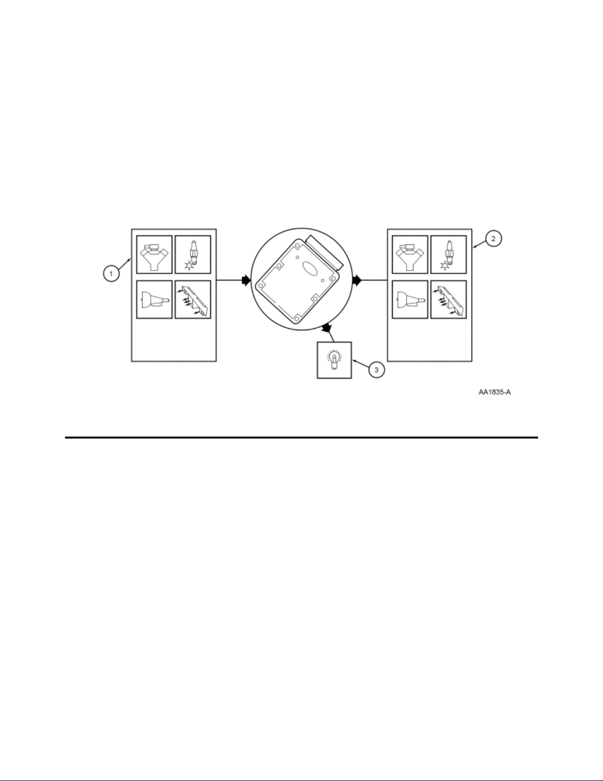
Cold Start Emission Reduction Component Monitor
Two different tests are carried out during the cold start emission reduction component monitor. The low idle
airflow test which checks the performance of the idle air control strategy and the spark timing monitor test
which checks the spark timing strategy.
Low Idle Air Flow Test
When the cold start emission reduction monitor is enabled, the powertrain control module (PCM) commands
the idle air control system to increase the RPM, which elevates engine air flow. While this cold start emission
reduction elevated air flow is requested, the low idle air flow test compares the measured idle air flow from
the mass air flow (MAF) sensor to the commanded idle air control strategy. For the purpose of detecting low
air flow failures, the low air flow test uses the measured air flow and the commanded air flow to create a low
air flow index.
Low idle air flow test operation:
DTC: P050A cold start idle air control system performance
!
Monitor execution: Once per driving cycle, from start up with the cold start emissions reduction active
!
Monitor sequence: none
!
Monitoring duration: 7 seconds
!
Low idle air flow test entry conditions:
Engine coolant temperature is between 4.4°C (40°F) and 82.2°C (180°F)
!
Barometric pressure is between 76.2 kPa (22.5 in-Hg) and 105 kPa (31 in-Hg)
!
Engine off soak time is at least 50 minutes
!
Throttle is at closed position
!
Page 25

Spark Timing Monitor Test
The PCM is equipped with a spark conduction capture circuit which measures the timing and duration of the
spark delivered by processing the flyback voltage signal from the primary side of the ignition coil. When the
cold start emission reduction monitor is enabled, the spark control strategy in the PCM commands the spark
timing strategy to retard the spark timing. While retarded spark timing is requested, the spark timing monitor
compares the measured spark timing from the spark conduction capture circuit to the commanded spark
timing from the spark control strategy. For the purpose of detecting spark timing failures, the spark timing
monitor increments a fault filter if the measured spark timing is advanced by more than 5 degrees from the
commanded spark timing. A failure is indicated if the fault filter exceeds a value of 200, equivalent to a
failure duration of approximately 4 seconds.
Spark timing monitor test operation:
DTC: P050B cold start ignition timing performance
!
Monitor execution: once per driving cycle, from start up with the cold start emission reduction monitor
!
active
Monitor sequence: none
!
Monitoring duration: 7 seconds
!
Spark timing monitor test entry conditions:
Engine speed is between 400 RPM and 2,000 RPM
!
Engine position and cylinder identification are synchronized
!
There is no concerns with the ignition coils primary circuits
!
Cold Start Emission Reduction System Monitor
The powertrain control module (PCM) uses the cold start emission reduction system monitor to calculate the
actual catalyst warm up temperature during a cold start. The actual catalyst warm up temperature
calculation uses measured engine speed, measured air mass and commanded spark timing inputs to the
PCM. The PCM then compares the actual temperature to the expected catalyst temperature model. The
expected catalyst temperature model calculation uses desired engine speed, desired air mass and desired
spark timing inputs to the PCM. The difference between the actual and expected temperatures is reflected in
a ratio. This ratio is a measure of how much loss of catalyst heating occurred over the period of time and
when compared with a calibrated threshold it helps the PCM to determine if the cold start emission reduction
system is working properly. This ratio correlates to tailpipe emissions, and a malfunction indicator lamp (MIL)
illuminates when the calibrated threshold is exceeded. The monitor is disabled if a concern is present in any
of the sensors or systems used for expected catalyst temperature model calculation.
Cold start emission reduction system monitor test operation:
DTC: P050E cold start engine exhaust temperature out of range
!
Monitor execution: once per driving cycle, from start up with the cold start emission reduction monitor
!
Page 26

active
Monitor sequence: the monitor collects data during first 15 seconds of the cold start
!
Monitoring duration: the monitor completes 300 seconds after initial engine start
!
Cold start emission reduction system monitor entry conditions:
Engine coolant temperature at the start of the monitor is between 1.67°C (35°F) and 37.78°C (100°F)
!
Barometric pressure is above 74.5 kPa (22 in-Hg)
!
Catalyst temperature at the start of the monitor is between 1.67°C (35°F) and 51.67°C (125°F)
!
Fuel level is above 15%
!
Power take-off operation is disabled
!
Page 27

2007 PCED On Board Diagnostics SECTION 1: Description and Operation
Procedure revision date: 03/29/2006
Comprehensive Component Monitor (CCM)
The CCM monitors for concerns in any powertrain electronic component or circuit that provides input or
output signals to the PCM that can affect emissions and is not monitored by another on board diagnostics
(OBD) monitor. Inputs and outputs are, at a minimum, monitored for circuit continuity or correct range of
values. Where feasible, inputs are also checked for rationality, and outputs are also checked for correct
functionality.
The CCM covers many components and circuits and tests them in various ways depending on the hardware,
function, and type of signal. For example, analog inputs such as throttle position or engine coolant
temperature are typically checked for opens, shorts, and out-of-range values. This type of monitoring is
carried out continuously. Some digital inputs like brake switch or crankshaft position rely on rationality
checks - checking to see if the input value makes sense at the current engine operating conditions. These
types of tests may require monitoring several components and can only be carried out under the appropriate
test conditions.
Outputs such as coil drivers are checked for opens and shorts by monitoring a feedback circuit or smart
driver associated with the output. Other outputs, such as relays, require additional feedback circuits to
monitor the secondary side of the relay. Some outputs are also monitored for correct function by observing
the reaction of the control system to a given change in the output command. An idle air control solenoid can
be functionally tested by monitoring the idle RPM relative to the target idle RPM. Some tests can only be
carried out under the appropriate test conditions. For example, the transmission shift solenoids can only be
tested when the PCM commands a shift.
The following is an example of some of the input and output components monitored by the CCM. The
component monitor may belong to the engine, ignition, transmission, air conditioning, or any other PCM
supported subsystem.
1. Inputs:
Air conditioning pressure (ACP) sensor, camshaft position (CMP) sensor, crankshaft position (CKP)
sensor, engine coolant temperature (ECT) sensor, engine oil temperature (EOT) sensor, fuel rail
pressure (FRP) sensor, fuel rail pressure temperature (FRPT) sensor, fuel tank pressure (FTP)
sensor, intake air temperature (IAT) sensor, mass air flow (MAF) sensor, throttle position (TP) sensor.
2. Outputs:
EVAP canister purge valve, EVAP canister vent (CV) solenoid, fuel injector, fuel pump (FP), idle air
control (IAC), intake manifold runner control (IMRC), shift solenoid, torque converter clutch (TCC)
solenoid, variable camshaft timing (VCT) actuator, wide open throttle A/C cutout (WAC).
3. CCM is enabled after the engine starts and is running. A DTC is stored in KAM and the MIL is
Page 28
illuminated after 2 driving cycles when a concern is detected. Many of the CCM tests are also carried
out during an on-demand self-test.
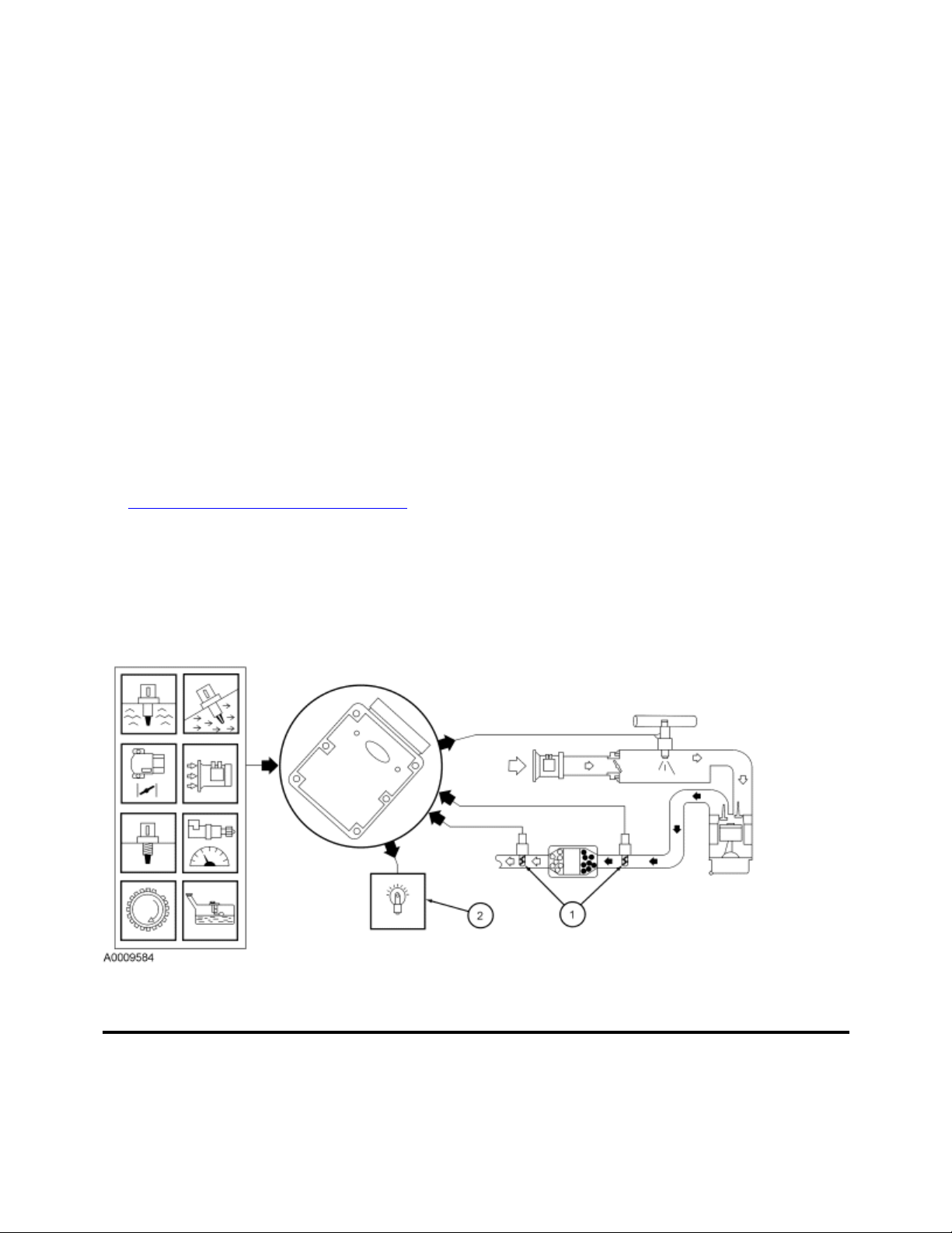
Comprehensive Component Monitor (CCM)
Page 29

2007 PCED On Board Diagnostics SECTION 1: Description and Operation
Procedure revision date: 03/29/2006
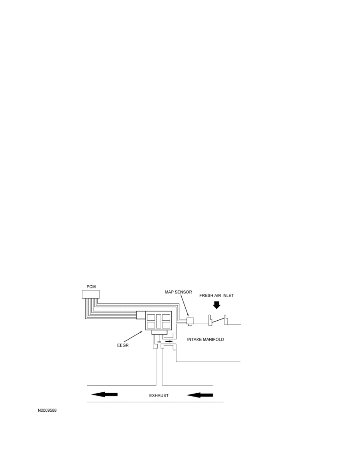
Electric Exhaust Gas Recirculation (EEGR) System Monitor
The EEGR system monitor is an on-board strategy designed to test the integrity and flow characteristics of
the EGR system. The monitor is activated during EGR system operation and after certain base engine
conditions are satisfied. Input from the engine coolant temperature (ECT) or cylinder head temperature
(CHT), intake air temperature (IAT), throttle position (TP), crankshaft position (CKP), mass air flow (MAF),
and manifold absolute pressure (MAP) sensors is required to activate the EGR system monitor. Once
activated, the EGR system monitor carries out each of the tests described below during the engine modes
and conditions indicated. Some of the EGR system monitor tests are also carried out during a key on engine
off (KOEO) or key on engine running (KOER) self-test.
The EEGR monitor consists of an electrical and functional test that checks the stepper motor and the EEGR
system for correct flow. The powertrain control module (PCM) controls the EEGR valve by commanding
from 0 to 52 discreet increments or steps to get the valve from fully closed to fully open. The stepper motor
electrical test is a continuous check of the 4 electric stepper motor coils and circuits to the PCM. A concern
is indicated if an open circuit, short to power, or short to ground has occurred in one or more of the stepper
motor coils or circuits for a calibrated period of time. If a concern has been detected, the EEGR system is
disabled, setting diagnostic trouble code (DTC) P0403. Additional monitoring is suspended for the remainder
of the drive cycle, or until the next engine startup.
After the vehicle has warmed up and normal EEGR flow rates are being commanded by the PCM, the
EEGR flow check is carried out. The flow test is carried out once per drive cycle when a minimum amount of
exhaust gas is requested and the remaining entry conditions required to initiate the test are satisfied. If a
concern is detected, the EEGR system, as well as the EEGR monitor, is disabled until the next engine
startup.
The EEGR flow test is done by observing the behavior of 2 different values: MAP - the analog MAP sensor
reading, and inferred MAP - calculated from the MAF sensor, throttle position and RPM. An EGR flow
concern is indicated by either a no flow condition or a low flow condition prior to exceeding 1.5 times the
applicable emission standard. The criteria used to determine which flow concern threshold applies is based
upon whether or not the applicable emission standards are exceeded on the federal test procedure test
cycle without EGR delivery.
When the flow test entry conditions have been satisfied, EEGR is commanded to flow at a calibrated test
rate (about 10%). At this time, the value of MAP is recorded (EGR-ON MAP). The value of inferred MAP
EGR-ON inferred MAP is also recorded. Next the EEGR is commanded off (0%). Again, the value of MAP is
recorded (EGR-OFF MAP). The value of EGR-OFF inferred MAP is also recorded. Typically, 7 such
ON/OFF samples are taken. After all the samples have been taken, the average EGR-ON MAP, EGR-ON
inferred MAP, EGR-OFF MAP and EGR-OFF inferred MAP values are stored.
The difference between the EGR-ON and EGR-OFF value is calculated as follows:
Page 30
MAP-delta equals EGR-ON MAP — EGR-OFF MAP
!
Inferred MAP-delta equals EGR-ON inferred MAP — EGR-OFF inferred MAP
!
If the sum of MAP-delta and inferred MAP-delta exceeds a maximum threshold or falls to less than a
minimum threshold, DTC P0400 (high or low flow concern) is registered.
As an additional check, if the EGR-ON MAP exceeds a maximum threshold (BARO, a calibrated value),
DTC P0400 (low flow) is set. This check is carried out to detect reduced EGR flow on systems where the
MAP sensor is located in the intake manifold plenum.
Note: BARO is inferred at engine startup using the KOEO MAP sensor reading. It is updated during high,
part-throttle or high RPM engine operation.
If the inferred ambient temperature is less than -7°C ( 2 0 °F ) , g r e a t e r t h a n 5 4 °C ( 1 3 0 °F ) , o r t h e a l t i t u de is
greater than 8,000 feet (BARO less than 22.5 in-Hg), the EEGR flow test cannot be reliably done. In these
conditions, the EEGR flow test is suspended and a timer starts to accumulate the time in these conditions.
When the vehicle leaves these extreme conditions, the timer starts to decrement, and if conditions permit,
attempts to complete the EGR flow monitor. If the timer reaches 800 seconds, the EEGR flow test is
disabled for the remainder of the current driving cycle and the EGR monitor is set to a ready condition.
A DTC P1408, like the P0400, indicates a EGR flow concern (outside the minimum or maximum limits) but is
only set during the KOER self-test. The P0400 and P0403 are MIL codes. P1408 is a non-MIL code.
Page 31

EEGR System Monitor
Page 32

2007 PCED On Board Diagnostics SECTION 1: Description and Operation
Procedure revision date: 03/29/2006
Electronic Engine Control (EEC) System
Overview
The EEC system provides optimum control of the engine and transmission through the enhanced capability
of the powertrain control module (PCM). The EEC system also has an on board diagnostics (OBD)
monitoring system with features and functions to meet federal regulations on exhaust emissions.
Some vehicle applications use a stand-alone transmission control module (TCM). Even though it is still part
of the EEC system, the TCM communicates with the PCM, the anti-lock brake system (ABS) module, the
instrument cluster, and the four-wheel drive (4WD) control modules using the high speed controller area
network (CAN) communications network. The TCM incorporates a stand alone OBD-II system. The TCM
independently processes and stores diagnostic trouble codes (DTCs), freeze frame, support PIDs as well as
J1979 Mode 09 CALID and calibration verification number. The TCM does not directly illuminate the
malfunction indicator lamp (MIL), but requests the PCM to do so. The TCM is located inside the transmission
assembly. It is not repairable, with the exception of reprogramming.
Below is a list of transmissions that use a TCM:
AWF21 (FWD) 6-speed automatic transmission
!
FNR5 (FWD) transmission
!
F21 (FWD) transmission
!
ZF CFT30 (FWD) continuously variable transmission (CVT)
!
ZF 6HP26 (RWD) transmission
!
ZF 6R (RWD)
!
6R60 (RWD)
!
For additional information on these transmissions and TCM diagnostics, refer to the Workshop Manual
Section 307-01, Automatic Transmission/Transaxle.
The EEC system has 2 major divisions: hardware and software. The hardware includes the PCM, sensors,
switches, actuators, solenoids, and interconnecting terminals. The software in the PCM provides the
strategy control for outputs (engine hardware) based on the values of the inputs to the PCM. The EEC
hardware and software are discussed in this section.
This section contains detailed descriptions of the operation of the EEC system input sensors and switches,
output actuators, solenoids, relays and connector pins (including other power-ground signals). For additional
information on the input sensors and output actuators, refer to Engine Control Components in this section.
The PCM receives information from a variety of sensor and switch inputs. Based on the strategy and
calibration stored within the memory chip, the PCM generates the appropriate output. The system is
Page 33

designed to minimize emissions and optimize fuel economy and driveability. The software strategy controls
the basic operation of the engine and transmission, provides the OBD strategy, controls the MIL,
communicates to the scan tool via the data link connector (DLC), allows for flash electrically erasable
programmable read only memory (EEPROM), provides idle air and fuel trim, and controls failure mode
effects management (FMEM).
Modifications to OBD Vehicles
Modifications or additions to the vehicle may cause incorrect operation of the OBD system. Install anti-theft
systems, remote starters, cellular telephones and aftermarket radios carefully.
by tapping into or running wires close to the powertrain control system wires or components.
Do not install these devices
Page 34

2007 PCED On Board Diagnostics SECTION 1: Description and Operation
Procedure revision date: 03/29/2006
Engine Control Components
Transmission inputs, which are not described in this section are discussed in the applicable Workshop
Note:
Manual transmission section.
Accelerator Pedal Position (APP) Sensor
The APP sensor is an input to the powertrain control module (PCM) and is used to determine the torque
demand. There are 3 pedal position signals in the sensor. Signal 1, APPS1, has a negative slope
(increasing angle, decreasing voltage) and signals 2 and 3, APPS2 and APPS3, both have a positive slope
(increasing angle, increasing voltage). During normal operation APPS1 is used as the indication of pedal
position by the strategy. The 3 pedal position signals make sure the PCM receives a correct input even if 1
signal has a concern. There are 2 reference voltage circuits and 2 signal return circuits for the sensor. For
additional information, refer to Torque Based Electronic Throttle Control (ETC) in this section.
Air Conditioning (A/C) Clutch Relay (A/CCR)
The PCM PIDs WAC and wide open throttle air conditioning cutoff fault (WACF) are used to monitor
Note:
the A/CCR output.
The A/CCR is wired normally open. There is no direct electrical connection between the A/C switch or
electronic automatic temperature control (EATC) module and the A/C clutch. The PCM receives a signal
indicating that A/C is requested. For some applications, this message is sent through the communications
network. When A/C is requested, the PCM checks other A/C related inputs that are available, such as A/C
pressure switch and A/C cycling switch. If these inputs indicate A/C operation is OK, and the engine
conditions are OK (coolant temperature, engine RPM, throttle position), the PCM grounds the A/CCR output,
closing the relay contacts and sending voltage to the A/CCR.
Air Conditioning (A/C) Cycling Switch
The A/C cycling switch may be wired to either the ACCS or ACPSW PCM input. When the A/C cycling
switch opens, the PCM turns off the A/C clutch. For information on the specific function of the A/C cycling
switch, refer to the Workshop Manual Section 412-00, Climate Control System. Also, refer to the applicable
Wiring Diagrams Manual for vehicle specific wiring.
If the ACCS signal is not received by the PCM, the PCM circuit will not allow the A/C to operate. For
additional information, refer to wide open throttle air conditioning cutoff (WAC) in this section.
Page 35

Some applications do not have a dedicated (separate) input to the PCM indicating that A/C is requested.
Volts
Resistance (K ohms)
100
212
194
176
158
140
122
104
This information is received by the PCM through the communication link.
Air Conditioning Evaporator Temperature (ACET) Sensor
The ACET sensor measures the evaporator air discharge temperature. The ACET sensor is a thermistor
device in which resistance changes with temperature. The electrical resistance of a thermistor decreases as
the temperature increases, and the resistance increases as the temperature decreases. The PCM sources a
low current 5 volts on the ACET circuit. With SIG RTN also connected to the ACET sensor, the varying
resistance changes the voltage drop across the sensor terminals. As A/C evaporator air temperature
changes, the varying resistance of the ACET sensor changes the voltage the PCM detects.
The ACET sensor is used to more accurately control A/C clutch cycling, improve defrost/demist
performance, and reduce A/C clutch cycling.
These values can vary 15 % due to sensor and VREF variations. Voltage values were calculated for
Note:
VREF equals 5.0 volts.
A/C EVAPORATOR TEMPERATURE
(ACET) SENSOR VOLTAGE AND
RESISTANCE
°C °F
90
80
70
60
50
40
30 86 2.74 24.25
20 68 3.26 37.34
10 50 3.73 58.99
0 32 4.14 95.85
-10 14 4.45 160.31
-20 -4 4.66 276.96
0.47 2.08
0.61 2.80
0.80 3.84
1.05 5.34
1.37 7.55
1.77 10.93
2.23 16.11
Page 36

Air Conditioning (A/C) High Pressure Switch
The A/C high pressure switch is used for additional A/C system pressure control. The A/C high pressure
switch is either dual function for multiple speed, relay controlled electric fan applications, or single function
for all others.
For refrigerant containment control, the normally closed high pressure contacts open at a predetermined A/C
pressure. This results in the A/C turning off, preventing the A/C pressure from rising to a level that would
open the A/C high pressure relief valve.
For fan control, the normally open medium pressure contacts close at a predetermined A/C pressure. This
grounds the ACPSW circuit input to the PCM. The PCM then turns on the high speed fan to help reduce the
pressure.
For additional information, refer to the Workshop Manual Section 412-00, Climate Control System or the
Wiring Diagrams Manual.
Air Conditioning Pressure (ACP) Sensor
The ACP sensor is located in the high pressure (discharge) side of the A/C system. The ACP sensor
provides a voltage signal to the PCM that is proportional to the A/C pressure. The PCM uses this information
for A/C clutch control, fan control and idle speed control.
Page 37

Page 38

Typical A/C Pressure Sensor
Brake Pedal Position (BPP) Switch
The BPP switch is sometimes referred to as the stoplamp switch. The BPP switch provides a signal to the
PCM indicating that the brakes are applied. The BPP switch is normally open and is mounted on the brake
pedal support. Depending on the vehicle application the BPP switch can be hardwired as follows:
to the PCM supplying battery positive voltage (B+) when the vehicle brake pedal is applied.
!
to the anti-lock brake system (ABS) module, or lighting control module (LCM), the BPP signal is then
!
broadcast over the network to be received by the PCM.
to the ABS traction control/stability assist module. The ABS module interprets the BPP switch input
!
along with other ABS inputs and generates an output called the driver brake application (DBA) signal.
The DBA signal is then sent to the PCM and to other BPP signal users.
Typical BPP Switch
Brake Pedal Switch (BPS)/Brake Deactivator Switch
The BPS, also called the brake deactivator switch, is for vehicle speed control deactivation. A normally
closed switch supplies battery positive voltage (B+) to the PCM when the brake pedal is not applied. When
the brake pedal is applied, the normally closed switch opens and power is removed from the PCM.
On some applications the normally closed BPS, along with the normally open BPP switch, are used for a
brake rationality test within the PCM. The PCM misfire monitor profile learn function may be disabled if a
brake switch concern occurs. If one or both brake pedal inputs to the PCM is not changing states when they
were expected to, a diagnostic trouble code (DTC) is set by the PCM strategy.
Camshaft Position (CMP) Sensor
The CMP sensor detects the position of the camshaft. The CMP sensor identifies when piston number 1 is
on its compression stroke. A signal is then sent to the PCM and used for synchronizing the sequential firing
of the fuel injectors. Coil-on-plug (COP) ignition applications use the CMP signal to select the correct ignition
Page 39

coil to fire.
Vehicles with 2 CMP sensors are equipped with variable camshaft timing (VCT). They use the second
sensor to identify the position of the camshaft on bank 2 as an input to the PCM.
There are 2 types of CMP sensors: the 3-pin connector Hall-effect type sensor and the 2-pin connector
variable reluctance type sensor.
Typical Synchronizer Hall-Effect CMP Sensor
Typical Variable Reluctance CMP Sensor
Canister Vent (CV) Solenoid
During the evaporative emissions (EVAP) leak check monitor, the CV solenoid seals the EVAP canister from
the atmospheric pressure. This allows the EVAP canister purge valve to obtain the target vacuum in the fuel
tank during the EVAP leak check monitor.
Page 40

Typical Canister Vent (CV) Solenoid
Check Fuel Cap Indicator
The check fuel cap indicator is a communications network message sent by the PCM. The PCM sends the
message to illuminate the lamp when the strategy determines that there is a failure in the vapor
management system due to the fuel filler cap not being sealed correctly. This would be detected by the
inability to pull vacuum in the fuel tank, after a fueling event.
Clutch Pedal Position (CPP) Switch
The CPP switch is an input to the PCM indicating the clutch pedal position. The PCM provides a low current
voltage on the CPP circuit. When the CPP switch is closed, this voltage is pulled low through the SIG RTN
circuit. The CPP input to the PCM is used to detect a reduction in engine load. The PCM uses the load
information for mass air flow and fuel calculations.
Typical Clutch Pedal Position (CPP) Switch
Page 41

Coil On Plug (COP)
The COP ignition operates similar to a standard coil pack ignition except each plug has one coil per plug.
The COP has 3 different modes of operation: engine crank, engine running, and CMP failure mode effects
management (FMEM). For additional information, refer to Ignition Systems in this section.
Coil On Plug (COP)
Coil Pack
The PCM provides a grounding switch for the coil primary circuit. When the switch is closed, voltage is
applied to the coil primary circuit. This creates a magnetic field around the primary coil. The PCM opens the
switch, causing the magnetic field to collapse, inducing the high voltage in the secondary coil windings and
firing the spark plug. The spark plugs are paired so that as one spark plug fires on the compression stroke,
the other spark plug fires on the exhaust stroke. The next time the coil is fired the order is reversed. The
next pair of spark plugs fire according to the engine firing order.
Coil packs come in 4-tower, 6-tower horizontal and series 5 6-tower models. Two adjacent coil towers share
a common coil and are called a matched pair. For 6-tower coil pack (6 cylinder) applications, the matched
pairs are 1 and 5, 2 and 6, and 3 and 4. For 4-tower coil pack (4 cylinder) applications, the matched pairs
are 1 and 4, and 2 and 3.
When the coil is fired by the PCM, spark is delivered through the matched pair towers to their respective
spark plugs. The spark plugs are fired simultaneously and are paired so that as one fires on the
compression stroke, the other spark plug fires on the exhaust stroke. The next time the coil is fired, the
situation is reversed. The next pair of spark plugs fire according to the engine firing order.
Page 42

Four-Tower Coil Pack
Typical Six-Tower Coil Pack
Cooling Fan Clutch
The cooling fan clutch is an electrically actuated viscous clutch that consists of 3 main elements:
! a working chamber
Page 43

a reservoir chamber
!
a cooling fan clutch actuator valve and a fan speed sensor (FSS)
!
The cooling fan clutch actuator valve controls the fluid flow from the reservoir into the working chamber.
Once viscous fluid is in the working chamber, shearing of the fluid results in fan rotation. The cooling fan
clutch actuator valve is activated with a pulse width modulated (PWM) output signal from the PCM. By
opening and closing the fluid port valve, the PCM can control the cooling fan clutch speed. The cooling fan
clutch speed is measured by a Hall-effect sensor and is monitored by the PCM during closed loop operation.
The PCM optimizes fan speed based on engine coolant temperature (ECT), engine oil temperature (EOT),
transmission fluid temperature (TFT), intake air temperature (IAT), or air conditioning requirements. When
an increased demand for fan speed is requested for vehicle cooling, the PCM monitors the fan speed
through the Hall-effect sensor. If a fan speed increase is required, the PCM outputs the PWM signal to the
fluid port, providing the required fan speed increase.
Cooling Fan Clutch with Fan Speed Sensor (FSS)
Crankshaft Position (CKP) Sensor
The CKP sensor is a magnetic transducer mounted on the engine block adjacent to a pulse wheel located
on the crankshaft. By monitoring the crankshaft mounted pulse wheel, the CKP is the primary sensor for
ignition information to the PCM. The pulse wheel has a total of 35 teeth spaced 10 degrees apart with one
empty space for a missing tooth. The 6.8L 10-cylinder pulse wheel has 39 teeth spaced 9 degrees apart and
one 9 degree empty space for a missing tooth. By monitoring the pulse wheel, the CKP sensor signal
indicates crankshaft position and speed information to the PCM. By monitoring the missing tooth, the CKP
sensor is also able to identify piston travel in order to synchronize the ignition system and provide a way of
tracking the angular position of the crankshaft relative to a fixed reference for the CKP sensor configuration.
Page 44

The PCM also uses the CKP signal to determine if a misfire has occurred by measuring rapid decelerations
between teeth.
Typical Crankshaft Position (CKP) Sensor
Cylinder Head Temperature (CHT) Sensor
The CHT sensor is a thermistor device in which resistance changes with the temperature. The electrical
resistance of a thermistor decreases as temperature increases, and the resistance increases as the
temperature decreases. The varying resistance affects the voltage drop across the sensor terminals and
provides electrical signals to the PCM corresponding to temperature.
The CHT sensor is installed in the cylinder head and measures the metal temperature. The CHT sensor can
provide complete engine temperature information and can be used to infer coolant temperature. If the CHT
sensor conveys an overheating condition to the PCM, the PCM initiates a fail-safe cooling strategy based on
information from the CHT sensor. A cooling system concern such as low coolant or coolant loss could cause
an overheating condition. As a result, damage to major engine components could occur. Using both the CHT
sensor and fail-safe cooling strategy, the PCM prevents damage by allowing air cooling of the engine and
limp home capability. For additional information, refer to Powertrain Control Software for Fail-Safe Cooling
Strategy in this section.
Typical CHT Sensor
Differential Pressure Feedback EGR (DPFE) Sensor
The DPFE sensor is a ceramic, capacitive-type pressure transducer that monitors the differential pressure
Page 45

across a metering orifice located in the orifice tube assembly. The DPFE sensor receives this signal through
2 hoses referred to as the downstream pressure hose (REF SIGNAL) and upstream pressure hose (HI
SIGNAL). The HI and REF hose connections are marked on the DPFE sensor housing for identification
(note that the HI signal uses a larger diameter hose). The DPFE sensor outputs a voltage proportional to the
pressure drop across the metering orifice and supplies it to the PCM as EGR flow rate feedback.
DPFE Sensor
DPFE Sensor — Tube Mounted
The tube mounted DPFE sensor is identical in operation as the larger plastic DPFE sensors and uses a 1.0
volt offset. The HI and REF hose connections are marked on the side of the sensor.
Page 46

Electronic Throttle Actuator Control (TAC)
DPFE Sensor — Tube Mounted
Electric Exhaust Gas Recirculation (EEGR) Valve
Depending on the application, the EEGR valve is a water cooled or an air cooled motor/valve assembly. The
motor is commanded to move in 52 discrete steps as it acts directly on the EEGR valve. The position of the
valve determines the rate of EGR. The built-in spring works to close the valve (against the motor opening
force).
EEGR Motor/Valve Assembly
Page 47

The electronic TAC is a DC motor controlled by the PCM (requires 2 wires). The gear ratio from the motor to
the throttle plate shaft is 17:1. There are 2 designs for the TAC, parallel and in-series. The parallel design
has the motor under the bore parallel to the plate shaft. The motor housing is integrated into the main
housing. The in-series design has a separate motor housing. Two springs are used; one is used to close the
throttle (main spring) and the other is in a plunger assembly that results in a default angle when no power is
applied. The force of the plunger spring is 2 times stronger than the main spring. The default angle is usually
set to result in a top vehicle speed of 48 km/h (30 mph). Typically this throttle angle is 7 to 8 degrees from
the hard stop angle. The closed throttle plate hard stop is used to prevent the throttle from binding in the
bore (~0.75 degree). This hard stop setting is not adjustable and is set to result in less airflow than the
minimum engine airflow required at idle. For additional information, refer to Torque Based Electronic Throttle
Control (ETC) in this section.
Electronic Throttle Body (ETB) Position Sensor
The ETB position sensor has 2 signal circuits in the sensor for redundancy. The redundant ETB position
signals are required for increased monitoring. The first ETB position sensor signal (TP1) has a negative
slope (increasing angle, decreasing voltage) and the second signal (TP2) has a positive slope (increasing
angle, increasing voltage). During normal operation the negative slope ETB position sensor signal (TP1) is
used by the control strategy as the indication of throttle position. The 2 ETB position sensor signals make
sure the PCM receives a correct input even if 1 signal has a concern. There is 1 reference voltage circuit
and 1 signal return circuit for the sensor. For additional information, refer to Torque Based Electronic
Throttle Control (ETC) in this section.
Engine Coolant Temperature (ECT) Sensor
The ECT sensor is a thermistor device in which resistance changes with temperature. The electrical
resistance of a thermistor decreases as the temperature increases, and the resistance increases as the
temperature decreases. The varying resistance changes the voltage drop across the sensor terminals and
provides electrical signals to the PCM corresponding to temperature.
Thermistor-type sensors are considered passive sensors. A passive sensor is connected to a voltage divider
network so that varying the resistance of the passive sensor causes a variation in total current flow. Voltage
that is dropped across a fixed resistor in a series with the sensor resistor determines the voltage signal at
the PCM. This voltage signal is equal to the reference voltage minus the voltage drop across the fixed
resistor.
The ECT measures the temperature of the engine coolant. The PCM uses the ECT input for fuel control and
for cooling fan control. There are 3 types of ECT sensors, threaded, push-in, and twist-lock. The ECT sensor
is located in an engine coolant passage.
Page 48

Typical Thread Type ECT Sensor
Engine Oil Temperature (EOT) Sensor
The EOT sensor is a thermistor device in which resistance changes with temperature. The electrical
resistance of a thermistor decreases as the temperature increases and the resistance increases as the
temperature decreases. The varying resistance changes the voltage drop across the sensor terminals and
provides electrical signals to the PCM corresponding to temperature.
Thermistor-type sensors are considered passive sensors. A passive sensor is connected to a voltage divider
network so that varying the resistance of the passive sensor causes a variation in total current flow. Voltage
that is dropped across a fixed resistor in a series with the sensor resistor determines the voltage signal at
the PCM. This voltage signal is equal to the reference voltage minus the voltage drop across the fixed
resistor.
The EOT sensor measures the temperature of the engine oil. The sensor is typically threaded into the
engine oil lubrication system. The PCM can use the EOT sensor input to determine the following:
On variable camshaft timing (VCT) applications the EOT input is used to adjust the VCT control gains
!
and logic for camshaft timing.
The PCM can use EOT sensor input in conjunction with other PCM inputs to determine oil
!
degradation.
The PCM can use EOT sensor input to initiate a soft engine shutdown. To prevent engine damage
!
from occurring as a result of high oil temperatures, the PCM has the ability to initiate a soft engine
shutdown. Whenever engine RPM exceeds a calibrated level for a certain period of time, the PCM
begins reducing power by disabling engine cylinders.
Typical EOT Sensor
Page 49

Evaporative Emission (EVAP) Canister Purge Valve
The EVAP canister purge valve may also be referred to as a vapor management valve (VMV).
Note:
The EVAP canister purge valve is part of the enhanced EVAP system that is controlled by the PCM. This
valve controls the flow of vapors (purging) from the EVAP canister to the intake manifold during various
engine operating modes. The EVAP canister purge valve is a normally closed valve. The EVAP canister
purge valve controls the flow of vapors by way of a solenoid, eliminating the need for an electronic vacuum
regulator and vacuum diaphragm. The PCM outputs a signal between 0 mA and 1,000 mA to control the
EVAP canister purge valve.
Typical EVAP Canister Purge Valve
Item Number Description
1 — Fuel Vapor to Intake Manifold
2 — Fuel Vapor to EVAP Canister
Exhaust Gas Recirculation (EGR) Orifice Tube Assembly
The orifice tube assembly is a section of tubing connecting the exhaust system to the intake manifold. The
assembly provides the flow path for the EGR to the intake manifold and also contains the metering orifice
and 2 pressure pick-up tubes. The internal metering orifice creates a measurable pressure drop across it as
the EGR valve opens and closes. This pressure differential across the orifice is picked up by the differential
pressure feedback EGR (DPFE) sensor which provides feedback to the PCM.
Page 50

EGR Orifice Tube Assembly
Exhaust Gas Recirculation (EGR) System Module (ESM)
The ESM is an integrated differential pressure feedback EGR (DPFE) system that functions in the same
manner as a conventional DPFE system. The various system components have been integrated into a
single component called the ESM. The flange of the valve portion of the ESM bolts directly to the intake
manifold with a metal gasket that forms the measuring orifice. This arrangement increases system reliability,
response time, and system precision. By relocating the EGR orifice from the exhaust to the intake side of the
EGR valve, the downstream pressure signal measures manifold absolute pressure (MAP). This MAP signal
is used for EGR correction and inferred barometric pressure (BARO) at key on. The system provides the
powertrain control module (PCM) with a differential DPFE signal, identical to a traditional DPFE system.
ESM
Page 51

Item Number Description
1 — EGR Vacuum Regulator Integrated into Upper Body
2 — DPFE and MAP Sensor
3 — Upstream DPFE Port
4 — Exhaust Flow
5 — Valve Seat
6 — Pin/Pintle
7 — To Intake Manifold Plenum
8 — Diaphragm
9 — EGR Spring
Exhaust Gas Recirculation (EGR) Vacuum Regulator Solenoid
The EGR vacuum regulator solenoid is an electromagnetic device used to regulate the vacuum supply to the
EGR valve. The solenoid contains a coil which magnetically controls the position of a disc to regulate the
vacuum. As the duty cycle to the coil increases, the vacuum signal passed through the solenoid to the EGR
valve also increases. Vacuum not directed to the EGR valve is vented through the solenoid vent to
atmosphere. Note that at 0% duty cycle (no electrical signal applied), the EGR vacuum regulator solenoid
allows some vacuum to pass, but not enough to open the EGR valve.
EGR Vacuum Regulator Solenoid
Page 52

Typical EGR Valve
Duty Cycle (%)
Hg
Hg
Hg
1.28
1.86
4.39
19.2
21.3
23.47
EGR VACUUM REGULATOR SOLENOID DATA
Vacuum Output
Minimum Nominal Maximum
In-
0 0 0 0.38
33 0.55
90 5.69
EGR vacuum regulator resistance: 26-40 Ohms
kPa In-
6.32
1.3
kPa In-
0.75 2.53
2.05 6.9
6.95
kPa
Exhaust Gas Recirculation (EGR) Valve
The EGR valve in the differential pressure feedback EGR (DPFE) system is a conventional, vacuumactuated. The valve increases or decreases the flow of EGR. As vacuum applied to the EGR valve
diaphragm overcomes the spring force, the valve begins to open. As the vacuum signal weakens, at 5.4 kPa
(1.6 in-Hg) or less, the spring force closes the valve. The EGR valve is fully open at about 15 kPa (4.5 inHg).
Since EGR flow requirement varies greatly, providing repair specifications on flow rate is impractical. The on
board diagnostic (OBD) system monitors the EGR valve function and triggers a diagnostic trouble code
(DTC) if the test criteria is not met. The EGR valve flow rate is not measured directly as part of the
diagnostic procedures.
Page 53

Item
Number
Description
1 — Vacuum Connection from EGR Vacuum Regulator
Solenoid
2 — Intake Manifold Connector
3 — Orifice Tube Connection
Fan Control
The PCM monitors certain parameters (such as engine coolant temperature, vehicle speed, A/C on/off
status, A/C pressure) to determine engine cooling fan needs.
For variable speed electric fan(s):
Page 54

The PCM controls the fan speed and operation using a duty cycle output on the fan control variable (FCV)
PCM OUTPUT
LOW SPEED
MEDIUM SPEED
HIGH SPEED
FAN OFF
circuit. The fan controller (located at or integral to the engine cooling fan assembly) receives the FCV
command and operates the cooling fan at the speed requested (by varying the power applied to the fan
motor).
FIVE HUNDRED/FREESTYLE/MONTEGO, FUSION/MILAN/ZEPHYR, CROWN VICTORIA/GRAND
MARQUIS, TOWN CAR: FCV DUTY CYCLE OUTPUT FROM PCM (negative duty cycle)
FCV Duty Cycle Command (NEGATIVE (-) duty
cycle) Cooling Fan Response/Speed
Greater than 0 but less than 5% Fan off, controller inactive
Greater than 5% but less than 10% Fan off, controller is in active/ready state
Crown Victoria/Grand Marquis, Town Car:
10% - 90%
Five Hundred/Freestyle/Montego,
Fusion/Milan/Zephyr:
30% - 90%
Greater than 90% but less than 95% 100%
Greater than 95% but less than 100% Fan off
Crown Victoria/Grand Marquis, Town Car:
Linear speed increase from 20% to 100%
Five Hundred/Freestyle/Montego,
Fusion/Milan/Zephyr:
Linear speed increase from 50% to 100%
For relay controlled fans:
The PCM controls the fan operation through the fan control (FC) (single speed fan applications), low fan
control (LFC), medium fan control (MFC), and/or high fan control (HFC) outputs. Some applications will have
the xFC circuit wired to 2 separate relays.
For 3-speed fans, although the PCM output circuits are called low, medium, and high fan control (FC),
cooling fan speed is controlled by a combination of these outputs. Refer to the following table.
2.0L FOCUS (with A/C) and TAURUS: PCM FC OUTPUT STATE FOR
COOLING FAN SPEEDS
LFC (FC1) ON ON ON OFF
MFC (FC2) ON OFF ON OFF
HFC (FC3) ON OFF OFF OFF
Page 55

PCM OUTPUT
LOW SPEED
MEDIUM SPEED
HIGH SPEED
FAN OFF
PCM OUTPUT
LOW SPEED
MEDIUM SPEED
HIGH SPEED
FAN OFF
2.3L ESCAPE: PCM FC OUTPUT STATE FOR COOLING FAN SPEEDS
LFC (FC1) ON ON ON OFF
MFC (FC2) OFF ON OFF (or ON) OFF
HFC (FC3) OFF OFF ON OFF
FREESTAR, MONTEREY: PCM FC OUTPUT STATE FOR COOLING
FAN SPEEDS
LFC (FC1) OFF ON ON OFF
MFC (FC2) ON OFF ON OFF
HFC (FC3) ON ON ON OFF
Fan Speed Sensor (FSS)
The FSS is a Hall-effect sensor that measures the cooling fan clutch speed by generating a waveform with a
frequency proportional to the fan speed. If the cooling fan clutch is moving at a relatively low speed, the
sensor produces a signal with a low frequency. As the cooling fan clutch speed increases, the sensor
generates a signal with a higher frequency. The powertrain control module (PCM) uses the frequency signal
generated by the FSS as a feedback for closed loop control of the cooling fan clutch. For additional
information on the cooling fan clutch, refer to the Cooling Fan Clutch in this section.
Page 56

Cooling Fan Clutch with FSS
Fuel Injectors
CAUTION: Do not apply battery positive voltage (B+) directly to the fuel injector electrical
connector terminals. The solenoids may be damaged internally in a matter of seconds.
The fuel injector is a solenoid-operated valve that meters fuel flow to the engine. The fuel injector is opened
and closed a constant number of times per crankshaft revolution. The amount of fuel is controlled by the
length of time the fuel injector is held open.
The fuel injector is normally closed, and is operated by a 12-volt source from either the electronic engine
control (EEC) power relay or fuel pump relay. The ground signal is controlled by the PCM.
The injector is the deposit resistant injector (DRI) type and does not have to be cleaned. However, it can be
flow checked and, if found outside of specification, a new fuel injector should be installed.
Typical Fuel Injector
Page 57

Item Number Description
1 — Fuel Filter Screen
2 — Connector
3 — Solenoid Coil
Fuel Level Input (FLI)
The FLI is a communications network message. Most vehicle applications use a potentiometer type FLI
sensor connected to a float in the FP module to determine fuel level.
Fuel Pump (FP) Module
The FP module is a device that contains the fuel pump and sender assembly. The fuel pump is located
inside the FP module reservoir and supplies fuel through the FP module manifold to the engine and FP
module jet pump. The jet pump continuously refills the reservoir with fuel, and a check valve located in the
manifold outlet maintains system pressure when the fuel pump is not energized. A flapper valve located in
the bottom of the reservoir allows fuel to enter the reservoir and prime the fuel pump during the initial fill.
Page 58

Mechanical Returnless Fuel Pump Module (FPM)
Page 59

Electronic Returnless Fuel Pump Module (FPM)
Fuel Pump Module and Reservoir
The fuel pump module is mounted inside the fuel tank in a reservoir. The pump has a discharge check valve
that maintains the system pressure after the key has been turned off to minimize starting concerns. The
reservoir prevents fuel flow interruptions during extreme vehicle maneuvers with low tank fill levels.
Page 60

Fuel Pump Module and Reservoir
Fuel Rail Pressure (FRP) Sensor
The FRP sensor is a diaphragm strain gauge device in which resistance changes with pressure. The
electrical resistance of a strain gauge increases as pressure increases, and the resistance decreases as the
pressure decreases. The varying resistance affects the voltage drop across the sensor terminals and
provides electrical signals to the PCM corresponding to pressure.
Strain gauge type sensors are considered passive sensors. A passive sensor is connected to a voltage
divider network so that varying the resistance of the passive sensor causes a variation in total current flow.
Voltage that is dropped across a fixed resistor in series with the sensor resistor determines the voltage
signal at the PCM. This voltage signal is equal to the reference voltage minus the voltage drop across the
fixed resistor.
The FRP sensor measures the pressure of the fuel near the fuel injectors. This signal is used by the PCM to
adjust the fuel injector pulse width and meter fuel to each engine combustion cylinder.
Page 61

Fuel Rail Pressure (FRP) Sensor
Fuel Rail Pressure Temperature (FRPT) Sensor
The FRPT sensor measures the pressure and temperature of the fuel in the fuel rail and sends these signals
to the PCM. The sensor uses the intake manifold vacuum as a reference to determine the pressure
difference between the fuel rail and the intake manifold. The relationship between fuel pressure and fuel
temperature is used to determine the possible presence of fuel vapor in the fuel rail.
The temperature sensing portion of the FRPT sensor is a thermistor device in which resistance changes with
temperature. The electrical resistance of the thermistor decreases as the temperature increases, and the
resistance increases as the temperature decreases. The varying resistance changes the voltage drop
across the sensor terminals and provides electrical signals to the PCM corresponding to temperature.
Both the pressure and temperature signals are used to control the speed of the fuel pump. The speed of the
fuel pump sustains fuel rail pressure which preserves fuel in its liquid state. The dynamic range of the fuel
injectors increase because of the higher rail pressure, which allows the injector pulse width to decrease.
Typical Fuel Rail Pressure Temperature (FRPT) Sensor
Fuel Rail Pulse Damper
The fuel rail pulse damper is located on the fuel rail and reduces the fuel system noise caused by the
pulsing of the fuel injectors. The vacuum port located on the damper is connected to manifold vacuum to
Page 62

avoid fuel spillage if the pulse damper diaphragm ruptures. The fuel rail pulse damper should not be
confused with a fuel pressure regulator; it does not regulate the fuel rail pressure.
Typical Fuel Rail Pulse Damper
Fuel Tank Pressure (FTP) Sensor
The FTP sensor or in-line FTP sensor is used to measure the fuel tank pressure.
Fuel Tank Pressure (FTP) Sensor
Page 63

In-Line Fuel Tank Pressure (FTP) Sensor
Heated Oxygen Sensor (HO2S)
The HO2S detects the presence of oxygen in the exhaust and produces a variable voltage according to the
amount of oxygen detected. A high concentration of oxygen (lean air/fuel ratio) in the exhaust produces a
voltage signal less than 0.4 volt. A low concentration of oxygen (rich air/fuel ratio) produces a voltage signal
greater than 0.6 volt. The HO2S provides feedback to the PCM indicating air/fuel ratio in order to achieve a
near stoichiometric air/fuel ratio of 14.7:1 during closed loop engine operation. The HO2S generates a
voltage between 0.0 and 1.1 volts.
Embedded with the sensing element is the HO2S heater. The heating element heats the sensor to a
temperature of 800°C (1,472°F). At approximately 300°C (572°F) the engine can enter closed loop
operation. The VPWR circuit supplies voltage to the heater. The PCM turns the heater on by providing the
ground when the correct conditions occur. The heater allows the engine to enter closed loop operation
sooner. The use of this heater requires the HO2S heater control to be duty cycled, to prevent damage to the
heater.
Page 64

Heated Oxygen Sensor (HO2S)
Idle Air Control (IAC) Valve
The IAC valve assembly is not adjustable and cannot be cleaned, also some IAC valves are normally
Note:
open and others are normally closed. Some IAC valves require engine vacuum to operate.
The IAC valve assembly controls the engine idle speed and provides a dashpot function. The IAC valve
assembly meters intake air around the throttle plate through a bypass within the IAC valve assembly and
throttle body. The PCM determines the desired idle speed or bypass air and signals the IAC valve assembly
through a specified duty cycle. The IAC valve responds by positioning the IAC valve to control the amount of
bypassed air. The PCM monitors engine RPM and increases or decreases the IAC duty cycle in order to
achieve the desired RPM.
The PCM uses the IAC valve assembly to control:
no touch start
!
cold engine fast idle for rapid warm-up
!
idle (corrects for engine load)
!
stumble or stalling on deceleration (provides a dashpot function)
!
over-temperature idle boost
!
Inertia Fuel Shutoff (IFS) Switch
The IFS switch is used in conjunction with the electric fuel pump. The purpose of the IFS switch is to shutoff
Page 65

the fuel pump if a collision occurs. It consists of a steel ball held in place by a magnet. When a sharp impact
occurs, the ball breaks loose from the magnet, rolls up a conical ramp and strikes a target plate which opens
the electrical contacts of the switch and shuts off the electric fuel pump. Once the switch is open, it must be
manually reset before restarting the vehicle. Refer to the Owner's Literature for the location of the IFS.
Typical Inertia Fuel Shutoff (IFS) Switch
Intake Air Temperature (IAT) Sensor
The IAT sensor is a thermistor device in which resistance changes with temperature. The electrical
resistance of a thermistor decreases as the temperature increases, and the resistance increases as the
temperature decreases. The varying resistance affects the voltage drop across the sensor terminals and
provides electrical signals to the PCM corresponding to temperature.
Thermistor-type sensors are considered passive sensors. A passive sensor is connected to a voltage divider
network so that varying the resistance of the passive sensor causes a variation in total current flow. Voltage
that is dropped across a fixed resistor in a series with the sensor resistor determines the voltage signal at
the PCM. This voltage signal is equal to the reference voltage minus the voltage drop across the fixed
resistor.
The IAT provides air temperature information to the PCM. The PCM uses the air temperature information as
a correction factor in the calculation of fuel, spark, and air flow.
The IAT sensor provides a quicker temperature change response time than the ECT or CHT sensor.
Currently there are 2 design types of IAT sensors used, a stand-alone/non-integrated type and a integrated
Page 66

type. Both types function the same, however the integrated type is incorporated into the mass air flow (MAF)
sensor instead of being a stand alone sensor.
Supercharged vehicles use 2 IAT sensors. Both sensors are thermistor type devices and operate as
described above. One is located before the supercharger at the air cleaner for standard OBD/cold weather
input, while a second sensor (IAT2) is located after the supercharger in the intake manifold. The IAT2 sensor
located after the supercharger provides air temperature information to the PCM to control spark and to help
determine charge air cooler (CAC) efficiency.
Typical Stand-Alone/Non-Integrated Intake Air Temperature (IAT) Sensors
Page 67

Knock Sensor (KS)
Typical Integrated Intake Air Temperature (IAT) Sensor Incorporated Into a Drop-in or Flange-type MAF
sensor
Intake Manifold Tuning Valve (IMTV)
WARNING: SUBSTANTIAL OPENING AND CLOSING TORQUE IS APPLIED BY THIS SYSTEM.
TO PREVENT INJURY, BE CAREFUL TO KEEP FINGERS AWAY FROM LEVER MECHANISMS WHEN
ACTUATED.
The IMTV is a motorized actuated unit mounted directly to the intake manifold. The IMTV actuator controls a
shutter device attached to the actuator shaft. There is no monitor input to the PCM with this system to
indicate shutter position.
The motorized IMTV unit is not energized below approximately 2,600 RPM. The shutter is in the closed
position not allowing airflow blend to occur in the intake manifold. The motorized unit is energized above
approximately 2,600 RPM. The motorized unit is commanded on by the PCM initially at a 100 percent duty
cycle to move the shutter to the open position, and then falling to approximately 50 percent to continue to
hold the shutter open.
Page 68

The KS is a tuned accelerometer on the engine which converts engine vibration to an electrical signal. The
PCM uses this signal to determine the presence of engine knock and to retard spark timing.
Two Types of Knock Sensor (KS)
Manifold Absolute Pressure (MAP) Sensor
The MAP sensor measures intake manifold absolute pressure. The PCM uses information from the MAP
sensor to measure how much exhaust gas is introduced into the intake manifold.
Typical Manifold Absolute Pressure (MAP) Sensor
Mass Air Flow (MAF) Sensor
The MAF sensor uses a hot wire sensing element to measure the amount of air entering the engine. Air
passing over the hot wire causes it to cool. This hot wire is maintained at 200°C (392°F) above the ambient
Page 69

temperature as measured by a constant cold wire. The current required to maintain the temperature of the
hot wire is proportional to the mass air flow. The MAF sensor then outputs an analog voltage signal to the
PCM proportional to the intake air mass. The PCM calculates the required fuel injector pulse width in order
to provide the desired air/fuel ratio. This input is also used in determining transmission electronic pressure
control (EPC), shift and torque converter clutch scheduling.
The MAF sensor is located between the air cleaner and the throttle body or inside the air cleaner assembly.
Most MAF sensors have integrated bypass technology with an integrated intake air temperature (IAT)
sensor. The hot wire electronic sensing element must be replaced as an assembly. Replacing only the
element may change the air flow calibration.
Diagram of Air Flow Through Throttle Body Contacting MAF Sensor Hot and Cold Wire (and IAT Sensor
Wire Where Applicable) Terminals.
Page 70

Typical Mass Air Flow (MAF) Sensor
Typical Drop-in Mass Air Flow (MAF) Sensor
Output Shaft Speed (OSS) Sensor
The OSS sensor provides the PCM with information about the rotational speed of an output shaft. The PCM
Page 71

uses the information to control and diagnose powertrain behavior. In some applications, the sensor is also
used as the source of vehicle speed. The sensor may be physically located in different places on the
vehicle, depending upon the specific application. The design of each speed sensor is unique and depends
on which powertrain control feature uses the information that is generated.
Power Steering Pressure (PSP) Sensor
The PSP sensor monitors the hydraulic pressure within the power steering system. The PSP sensor voltage
input to the PCM changes as the hydraulic pressure changes. The PCM uses the input signal from the PSP
sensor to compensate for additional loads on the engine by adjusting the idle RPM and preventing engine
stall during parking maneuvers. Also, the PSP sensor signals the PCM to adjust the transmission electronic
pressure control (EPC) pressure during increased engine load, for example, during parking maneuvers.
Typical Power Steering Pressure (PSP) Sensor
Power Steering Pressure (PSP) Switch
The PSP switch monitors the hydraulic pressure within the power steering system. The PSP switch is a
normally closed switch that opens as the hydraulic pressure increases. The PCM provides a low current
voltage on the PSP circuit. When the PSP switch is closed, this voltage is pulled low through the SIG RTN
circuit. The PCM uses the input signal from the PSP switch to compensate for additional loads on the engine
by adjusting the idle RPM and preventing engine stall during parking maneuvers. Also, the PSP switch
signals the PCM to adjust the transmission electronic pressure control (EPC) pressure during increased
engine load, for example during parking maneuvers.
Typical Power Steering Pressure (PSP) Switch
Page 72

Power Take-Off (PTO) Switch and Circuits
The PTO circuit is used by the PCM to disable some of the on board diagnostics (OBD) monitors during
PTO operation. The PTO switch is normally open. When the PTO unit is activated, the PTO switch is closed
and battery voltage is supplied to the PTO input circuit. This indicates to the PCM that an additional load is
being applied to the engine. The PTO indicator lamp illuminates when the PTO system is functioning
correctly and flashes when the PTO system is damaged.
When the PTO unit is activated, the PCM disables some OBD monitors, which may not function reliably
during PTO operation. Without the PTO circuit information to the PCM, false DTCs may be set during PTO
operation. Prior to an Inspection/Maintenance test, operate the vehicle with the PTO disengaged long
enough to successfully complete the OBD Monitors.
PTO Circuits Description
The 3 PTO input circuits are PTO mode, PTO engage, and PTO RPM.
The PTO engage circuit is used when the operator is requesting the PCM to check the needed inputs
required to initiate the PTO engagement.
The PTO RPM circuit is used for the operator to request additional engine RPM for PTO operation.
Powertrain Control Module - Vehicle Speed Output (PCM-VSO)
The PCM-VSO speed signal subsystem generates vehicle speed information for distribution to the vehicle's
electrical/electronic modules and subsystems that require vehicle speed data. This subsystem senses the
transmission output shaft speed with a sensor. The data is processed by the PCM and distributed as a
hardwired signal or as a message on the vehicle communication network.
The key features of the PCM-VSO system are to:
infer vehicle movement from the output shaft speed (OSS) sensor signal.
!
convert transmission output shaft rotational information to vehicle speed information.
!
compensate for tire size and axle ratio with a programmed calibration variable.
!
use a transfer case speed sensor (TCSS) for four wheel drive (4WD) applications.
!
distribute vehicle speed information as a multiplexed message and/or an analog signal.
!
The signal from a non-contact shaft sensor OSS or TCSS mounted on the transmission (automatic, manual,
or 4WD transfer case) is sensed directly by the PCM. The PCM converts the OSS or TCSS information to
8,000 pulses per mile, based on a tire and axle ratio conversion factor. This conversion factor is
programmed into the PCM at the time the vehicle is assembled and can be reprogrammed in the field for
Page 73

servicing changes in the tire size and axle ratio. The PCM transmits the computed vehicle speed and
distance traveled information to all the vehicle speed signal users on the vehicle. VSO information can be
transmitted by a hardwired interface between the vehicle speed signal user and the PCM, or by a speed and
odometer data message through the vehicle communication network data link.
The PCM-VSO hardwired signal wave form is a DC square wave with a voltage level of 0 to VBAT. Typical
output operating range is 1.3808 Hz per 1 km/h (2.22 Hz per mph).
Secondary Air Injection (AIR) Bypass Solenoid
The secondary AIR bypass solenoid is used by the PCM to control vacuum to the secondary air injection
diverter (AIR diverter) valve. The secondary AIR bypass solenoid is a normally closed solenoid. The
secondary AIR bypass solenoid also has a filtered vent feature to permit vacuum release.
Secondary AIR Bypass Solenoid
Secondary AIR Diverter Valve
The secondary AIR diverter valve is used with the secondary AIR pump to provide on/off control of air to the
exhaust manifold and catalytic converter. When the secondary AIR pump is on and vacuum is supplied to
the AIR diverter valve, air passes the integral check valve disk. When the secondary AIR pump is off, and
vacuum is removed from the AIR diverter valve, the integral check valve disk is held on the seat and stops
air from being drawn into the exhaust system and prevents the back flow of the exhaust into the secondary
AIR system.
Page 74

Starter Motor Request (SMR) Circuit
Secondary AIR Diverter Valve
Secondary AIR Pump
The secondary AIR pump provides pressurized air to the secondary AIR system. The secondary AIR pump
functions independently of RPM and is controlled by the PCM. The secondary AIR pump is only used for
short periods of time. Delivery of air is dependent on the amount of system backpressure and system
voltage. The secondary AIR pump draws dry filtered air from the intake air system downstream of the
MAF/IAT sensor. For additional information on the secondary AIR injection system, refer to Secondary Air
Injection (AIR) System in this section.
Secondary Air Pump
Page 75

The SMR circuit provides the PCM with a signal from the ignition switch to the PCM. The input is pulled high
when the key is in the START position and the transmission range sensor ignition lockout circuit allows the
starter to engage.
Throttle Position (TP) Sensor
The TP sensor is a rotary potentiometer sensor that provides a signal to the PCM that is linearly proportional
to the throttle plate/shaft position. The sensor housing has a 3-blade electrical connector that may be gold
plated. The gold plating increases the corrosion resistance on the terminals and increases the connector
durability. The TP sensor is mounted on the throttle body. As the TP sensor is rotated by the throttle shaft, 4
operating conditions are determined by the PCM from the TP. The operating conditions are:
closed throttle (includes idle or deceleration)
!
part throttle (includes cruise or moderate acceleration)
!
wide open throttle (includes maximum acceleration or de-choke on crank)
!
throttle angle rate
!
Typical TP Sensor
Transmission Control Indicator Lamp (TCIL)
The TCIL is an output signal from the PCM that controls the lamp on/off function depending on the
engagement or disengagement of overdrive.
Transmission Control Switch (TCS)
The TCS signals the PCM with VPWR whenever the TCS is pressed. On vehicles with this feature, the
transmission control indicator lamp (TCIL) illuminates when the TCS is cycled to disengage overdrive.
Page 76

Typical Transmission Control Switch (TCS)
Typical Transmission Control Switch (TCS)
Vapor Management Valve (VMV)
See the description of the EVAP canister purge valve in this section.
Vehicle Speed Sensor (VSS)
The VSS is a variable reluctance or hall-effect sensor that generates a waveform with a frequency that is
proportional to the speed of the vehicle. If the vehicle is moving at a relatively low velocity, the sensor
produces a signal with a low frequency. As the vehicle velocity increases, the sensor generates a signal with
a higher frequency. The PCM uses the frequency signal generated by the VSS (and other inputs) to control
such parameters as fuel injection, ignition control, transmission/transaxle shift scheduling, and torque
converter clutch scheduling.
Page 77

Typical Vehicle Speed Sensor (VSS)
Page 78

2007 PCED On Board Diagnostics SECTION 1: Description and Operation
Procedure revision date: 03/29/2006
Evaporative Emission (EVAP) Leak Check Monitor
The EVAP leak check monitor is an on-board strategy designed to detect a leak from a hole (opening) equal
to or greater than 0.508 mm (0.020 inch) in the enhanced EVAP system. The correct function of the
individual components of the enhanced EVAP system, as well as its ability to flow fuel vapor to the engine, is
also examined. The EVAP leak check monitor relies on the individual components of the enhanced EVAP
system to either allow a natural vacuum to occur in the fuel tank or apply engine vacuum to the fuel tank and
then seal the entire enhanced EVAP system from the atmosphere. The fuel tank pressure is then monitored
to determine the total vacuum lost (bleed-up) for a calibrated period of time. Inputs from the engine coolant
temperature (ECT) sensor or cylinder head temperature (CHT) sensor, intake air temperature (IAT) sensor,
mass air flow (MAF) sensor, vehicle speed, fuel level input (FLI) and fuel tank pressure (FTP) sensor are
required to enable the EVAP leak check monitor.
During the EVAP leak check monitor repair verification drive cycle, clearing the continuous diagnostic
trouble codes (DTCs) and resetting the emission monitors information in the powertrain control module
(PCM) bypasses the minimum soak time required to complete the monitor. The EVAP leak check monitor
does not run if the key is turned off after clearing the continuous DTCs and resetting the emission monitors
information in the PCM. The EVAP leak check monitor does not run if a MAF sensor concern is present. The
EVAP leak check monitor does not initiate until the heated oxygen sensor (HO2S) monitor is complete.
If the vapor generation is high on some vehicle enhanced EVAP systems, where the monitor does not pass,
the result is treated as a no test. Therefore, the test is complete for the day.
Some vehicle applications have an engine off natural vacuum (EONV) check as part of the EVAP leak check
monitor.
Engine On EVAP Leak Check Monitor
The engine on EVAP leak check monitor is executed by the individual components of the enhanced EVAP
system as follows:
1. The EVAP canister purge valve, also known as the vapor management valve (VMV), is used to
control the flow of vacuum from the engine and create a target vacuum on the fuel tank.
2. The canister vent (CV) solenoid is used to seal the EVAP system from the atmosphere. It is closed by
the PCM (100% duty cycle) to allow the EVAP canister purge valve to obtain the target vacuum on
the fuel tank.
3. The FTP sensor is used by the engine on EVAP leak check monitor to determine if the target vacuum
necessary to carry out the leak check on the fuel tank is reached. Some vehicle applications with the
engine on EVAP leak check monitor use a remote in-line FTP sensor. Once the target vacuum on the
fuel tank is achieved, the change in fuel tank vacuum over a calibrated period of time determines if a
Page 79

leak exists.
4. If the initial target vacuum cannot be reached, DTC P0455 (gross leak detected) is set. The engine on
EVAP leak check monitor aborts and does not continue with the leak check portion of the test.
For some vehicle applications, if the initial target vacuum cannot be reached after a refueling event
and the purge vapor flow is excessive, DTC P0457 (fuel cap off) is set. If the initial target vacuum
cannot be reached and the purge flow is too small, DTC P1443 (no purge flow condition) is set.
If the initial target vacuum is exceeded, a system flow concern exists and DTC P1450 (unable to
bleed-up fuel tank vacuum) is set. The engine on EVAP leak check monitor aborts and does not
continue with the leak check portion of the test.
If the target vacuum is obtained on the fuel tank, the change in the fuel tank vacuum (bleed-up) is
calculated for a calibrated period of time. The calculated change in fuel tank vacuum is compared to a
calibrated threshold for a leak from a hole (opening) of 1.016 mm (0.040 inch) in the enhanced EVAP
system. If the calculated bleed-up is less than the calibrated threshold, the enhanced EVAP system
passes. If the calibrated bleed-up exceeds the calibrated threshold, the test aborts. The test can be
repeated up to 3 times.
If the bleed-up threshold is still being exceeded after 3 tests, a vapor generation test must be carried
out before DTC P0442 (small leak detected) is set. This is accomplished by returning the enhanced
EVAP system to atmospheric pressure by closing the EVAP canister purge valve and opening the CV
solenoid. Once the FTP sensor observes the fuel tank is at atmospheric pressure, the CV solenoid
closes and seals the enhanced EVAP system.
The fuel tank pressure build-up, over a calibrated period of time is compared to a calibrated threshold
for pressure build-up due to vapor generation.
If the fuel tank pressure build-up exceeds the threshold, the leak test results are invalid due to vapor
generation. The engine on EVAP leak check monitor attempts to repeat the test again.
If the fuel tank pressure build-up does not exceed the threshold, the leak test results are valid and
DTC P0442 is set.
5. If the 1.016 mm (0.40 inch) test passes, the test time is extended to allow the 0.508 mm (0.020 inch)
test to run.
The calculated change in fuel vacuum over the extended time is compared to a calibrated threshold
for a leak from a 0.508 mm (0.020 inch) hole (opening).
If the calculated bleed-up exceeds the calibrated threshold, the vapor generation test is run. If the
vapor generation test passes (no vapor generation), an internal flag is set in the PCM to run a 0.508
mm (0.020 inch) test at idle (vehicle stopped).
On the next start following a long engine off period, the enhanced EVAP system is sealed and
evacuated for the first 10 minutes of operation.
Page 80

If the appropriate conditions are met, a 0.508 mm (0.020 inch) leak check is conducted at idle.
If the test at idle fails, a DTC P0456 is set. There is no vapor generation test with the idle test.
6. The MIL is activated for DTCs P0442, P0455, P0456, P0457, P1443, and P1450 (or P0446) after 2
occurrences of the same concern. The MIL can also be activated for any enhanced EVAP system
component DTCs in the same manner. The enhanced EVAP system component DTCs P0443,
P0452, P0453, and P1451 are tested as part of the CCM.
Evaporative Emission (EVAP) Leak Check Monitor
Engine Off Natural Vacuum (EONV) EVAP Leak Check Monitor
The EONV EVAP leak check monitor is executed during key off, after the engine on EVAP leak check
monitor is completed. The EONV EVAP leak check monitor determines a leak is present when the naturally
occurring change in fuel tank pressure or vacuum does not exceed a calibrated limit during a calibrated
amount of time. A separate, low power consuming, microprocessor in the PCM manages the EONV leak
check. The engine off EVAP leak check monitor is executed by the individual components of the enhanced
EVAP system as follows:
1. The EVAP canister purge valve, also known as the vapor management valve (VMV), is normally
closed at key off.
2. The normally open canister vent (CV) remains open for a calibrated amount of time to allow the fuel
tank pressure to stabilize with the atmosphere. During this time period the FTP sensor is monitored
for an increase in pressure. If pressure remains below a calibrated limit the CV is closed by the PCM
(100% duty cycle) and seals the EVAP system from the atmosphere.
3. The FTP sensor is used by the EONV EVAP leak check monitor to determine if the target pressure or
vacuum necessary to complete the EONV EVAP leak check monitor on the fuel tank is reached.
Page 81

Some vehicle applications with the EONV EVAP leak check monitor use a remote in-line FTP sensor.
If the target pressure or vacuum on the fuel tank is achieved within the calibrated amount of time, the
test is complete.
4. The EONV EVAP leak check monitor uses the naturally occurring change in fuel tank pressure as a
means to detect a leak in the EVAP system. At key off, a target pressure and vacuum is determined
by the PCM. These target values are based on the fuel level and the ambient temperature at key off.
As the fuel tank temperature increases, the pressure in the tank increases and as the temperature
decreases a vacuum develops. If a leak is present in the EVAP system the fuel tank pressure or
vacuum does not exceed the target value during the testing time period. The EONV EVAP leak check
monitor begins at key off.
After key off the normally open canister vent (CV) remains open for a calibrated amount of time to
allow the fuel tank pressure to stabilize with the atmosphere. During this time period the FTP sensor
is monitored for an increase in pressure. If pressure remains below a calibrated limit the CV is closed
by the PCM (100% duty cycle) and seals the EVAP system from the atmosphere.
If the pressure on the fuel tank decreases after the EVAP system is sealed, the EONV EVAP leak
check monitor begins to monitor the fuel tank pressure. When the target vacuum is exceeded within
the calibrated amount of time the test completes and the fuel tank pressure and time since key off
information is stored. If the target vacuum is not reached in the calibrated amount of time, a leak is
suspected and the fuel tank pressure and time since key off information is stored.
If the pressure on the fuel tank increases after the EVAP system is sealed, but does not exceed the
target pressure within a calibrated amount of time the CV is opened to allow the fuel tank pressure to
again stabilize with the atmosphere. After a calibrated amount of time the CV is closed by the PCM
and seals the EVAP system. When the fuel tank pressure exceeds either the target pressure or
vacuum within the calibrated amount of time the test completes and the fuel tank pressure and time
since key off information is stored. If the target pressure or vacuum is not reached in the calibrated
amount of time, a leak is suspected and the fuel tank pressure and time since key off information is
stored.
When a leak is suspected, the PCM uses the stored fuel tank pressure and time since key off
information from an average run of 4 tests to suspect a leak. Some vehicles use an alternative
method of a single run of 5 tests to determine the presence of a leak. If a leak is still suspected after 2
consecutive runs of 4 tests, (8 total tests) or 1 run of 5 tests, DTC P0456 is set and the MIL is
illuminated.
5. The EONV EVAP leak check monitor is controlled by a separate low power consuming
microprocessor inside the PCM. The fuel level indicator, fuel tank pressure, and battery voltage are
inputs to the microprocessor. The microprocessor outputs are the CV solenoid and the stored test
information. If the separate microprocessor is unable to control the CV solenoid or communicate with
other processors DTC P260F is set.
6. The MIL is activated for DTCs P0456 and P260F. The MIL can also be activated for any enhanced
EVAP system component DTCs in the same manner. The enhanced EVAP system component DTCs
P0443, P0446, P0452, P0453, and P1451 are tested as part of the CCM.
Page 82

EONV EVAP Leak Check Monitor
Page 83

2007 PCED On Board Diagnostics SECTION 1: Description and Operation
Procedure revision date: 03/29/2006
Evaporative Emission (EVAP) Systems
Overview
The EVAP system prevents fuel vapor build-up in the sealed fuel tank. Fuel vapors trapped in the sealed
tank are vented through the vapor valve assembly on top of the tank. The vapors leave the valve assembly
through a single vapor line and continue to the EVAP canister for storage until the vapors are purged to the
engine for burning.
All applications required to meet on board diagnostics (OBD) regulations use the enhanced EVAP system.
Some applications also incorporate an on-board refueling vapor recovery (ORVR) system. Refer to the
Workshop Manual Section 303-13, Evaporative Emissions for vehicle specific information.
Enhanced Evaporative Emission (EVAP) System
The enhanced EVAP system consists of a fuel tank, fuel filler cap, fuel tank mounted or in-line fuel vapor
control valve, fuel vapor vent valve, EVAP canister, fuel tank mounted or fuel pump mounted or in-line fuel
tank pressure (FTP) sensor, EVAP canister purge valve or vapor management valve (VMV), intake manifold
hose assembly, EVAP canister vent (CV) solenoid, powertrain control module (PCM) and connecting wires,
and fuel vapor hoses. For additional information on the EVAP system components, refer to Engine Control
Components in this section.
1. The enhanced EVAP system uses inputs from the engine coolant temperature (ECT) sensor or
cylinder head temperature (CHT) sensor, the intake air temperature (IAT) sensor, the mass air flow
(MAF) sensor, the vehicle speed and the FTP sensor to provide information about engine operating
conditions to the PCM. The fuel level input (FLI) and FTP sensor signals to the PCM are used by the
PCM to determine activation of the EVAP leak check monitor based on the presence of vapor
generation or fuel sloshing.
2. The PCM determines the desired amount of purge vapor flow to the intake manifold for a given
engine condition. The PCM can then output the required signal to the EVAP canister purge valve or
VMV. The PCM uses the enhanced EVAP system inputs to evacuate the system using the EVAP
canister purge valve or VMV, seals the enhanced EVAP system from the atmosphere using the CV
solenoid, and uses the FTP sensor to observe total vacuum lost for a period of time.
3. The CV solenoid seals the enhanced EVAP system to atmosphere during the EVAP leak check
monitor.
4. The PCM outputs a variable current (between 0 mA and 1,000 mA) to the solenoid on the EVAP
canister purge valve or VMV.
5. The FTP sensor monitors the fuel tank pressure during engine operation and continuously transmits
Page 84

an input signal to the PCM. During the EVAP monitor testing, the FTP sensor monitors the fuel tank
pressure or vacuum bleed-up.
6. The fuel tank mounted fuel vapor vent valve assembly and the fuel tank mounted fuel vapor control
valve (or remote fuel vapor control valve) are used in the enhanced EVAP system to control the flow
of fuel vapor entering the engine. All of these valves also prevent fuel tank overfilling during refueling
operation and prevent liquid fuel from entering the EVAP canister and the EVAP canister purge valve
or VMV under any vehicle altitude, handling, or rollover condition.
7. The enhanced EVAP system, including all the fuel vapor hoses, can be checked when a leak is
detected by the PCM. Refer to the Workshop Manual Section 303-13, Evaporative Emissions for
information on leak detection tools and procedures.
Enhanced Evaporative Emission System
Page 85

Page 86

2007 PCED On Board Diagnostics SECTION 1: Description and Operation
Procedure revision date: 03/29/2006
Exhaust Gas Recirculation (EGR) System Monitor — Differential
Pressure Feedback EGR (DPFE) and EGR System Module (ESM)
The EGR system monitor is an on-board strategy designed to test the integrity and flow characteristics of the
EGR system. The monitor is activated during EGR system operation and after certain base engine
conditions are satisfied. Input from the engine coolant temperature (ECT) or cylinder head temperature
(CHT), intake air temperature (IAT), throttle position (TP), and crankshaft position (CKP) sensors is required
to activate the monitor. Once activated, the EGR system monitor carries out each of the tests described
below during the engine modes and conditions indicated. Some of the EGR system monitor tests are also
carried out during an on-demand self-test.
1. The DPFE sensor and circuit are continuously tested for opens and shorts. The monitor checks for
the DPFE circuit voltage to exceed the maximum or minimum allowable limits.
The diagnostic trouble codes (DTCs) associated with this test are P0405 and P0406.
2. The EGR vacuum regulator solenoid is continuously tested for opens and shorts. The monitor looks
for an EVR circuit voltage that is inconsistent with the EVR circuit commanded output state.
The DTC associated with this test is P0403.
3. The test for a stuck open EGR valve or EGR flow at idle is continuously carried out at idle (TP sensor
indicating closed throttle). The monitor compares the DPFE circuit voltage at idle to the DPFE circuit
voltage stored during key on engine off (KOEO) to determine if EGR flow is present at idle.
The DTC associated with this test is P0402.
4. The DPFE sensor hoses are tested once per drive cycle for disconnect and plugging. The test is
carried out with the EGR valve closed and during a period of acceleration. The powertrain control
module (PCM) momentarily commands the EGR valve closed. The monitor looks for the DPFE
sensor voltage to be inconsistent for a no flow voltage. A voltage increase or decrease during
acceleration while the EGR valve is closed may indicate a concern with a signal hose during this test.
The DTCs associated with this test are P1405 and P1406 (DPFE systems only).
5. The EGR flow rate test is carried out during a steady state when the engine speed and load are
moderate and the EGR vacuum regulator duty cycle is high. The monitor compares the actual DPFE
circuit voltage to a desired EGR flow voltage for that state to determine if the EGR flow rate is
acceptable or insufficient. This is a system test and may trigger a DTC for any concern causing the
EGR system to fail.
The DTC associated with this test is P0401. DTC P1408 is similar to P0401 but is carried out during
Page 87

key on engine running (KOER) self-test conditions.
6. The MIL is activated after one of the above tests fails on 2 consecutive drive cycles.
EGR System Monitor - DPFE
Page 88

2007 PCED On Board Diagnostics SECTION 1: Description and Operation
Procedure revision date: 03/29/2006
Exhaust Gas Recirculation (EGR) Systems
Overview
The EGR system controls the oxides of nitrogen (NO x ) emissions. Small amounts of exhaust gases are
recirculated back into the combustion chamber to mix with the air/fuel charge. The combustion chamber
temperature is reduced, lowering NO x emissions.
Differential Pressure Feedback EGR (DPFE) System
The DPFE system consists of a DPFE sensor, EGR vacuum regulator solenoid, EGR valve, orifice tube
assembly, powertrain control module (PCM), and connecting wires and vacuum hoses. For additional
information on the DPFE system, refer to Engine Control Components in this section. Operation of the
system is as follows:
1. The DPFE system receives signals from the engine coolant temperature (ECT) sensor or cylinder
head temperature (CHT) sensor, intake air temperature (IAT) sensor, throttle position (TP) sensor,
mass air flow (MAF) sensor, and crankshaft position (CKP) sensor to provide information on engine
operating conditions to the PCM. The engine must be warm, stable, and running at a moderate load
and RPM before the EGR system is activated. The PCM deactivates EGR during idle, extended wide
open throttle, or whenever a concern is detected in an EGR component or EGR required input.
2. The PCM calculates the desired amount of EGR flow for a given engine condition. It then determines
the desired pressure drop across the metering orifice required to achieve that flow and outputs the
corresponding signal to the EGR vacuum regulator solenoid.
3. The EGR vacuum regulator solenoid receives a variable duty cycle signal (0 to 100%). The higher the
duty cycle the more vacuum the solenoid diverts to the EGR valve.
4. The increase in vacuum acting on the EGR valve diaphragm overcomes the valve spring and begins
to lift the EGR valve pintle off its seat, causing exhaust gas to flow into the intake manifold.
5. Exhaust gas flowing through the EGR valve must first pass through the EGR metering orifice. With
one side of the orifice exposed to exhaust backpressure and the other to the intake manifold, a
pressure drop is created across the orifice whenever there is EGR flow. When the EGR valve closes,
there is no longer flow across the metering orifice and pressure on both sides of the orifice is the
same. The PCM constantly targets a desired pressure drop across the metering orifice to achieve the
desired EGR flow.
6. The DPFE sensor measures the actual pressure drop across the metering orifice and relays a
Page 89

proportional voltage signal (0 to 5 volts) to the PCM. The PCM uses this feedback signal to correct for
any errors in achieving the desired EGR flow.
DPFE System Operation
Electric Exhaust Gas Recirculation (EEGR) System
Highlights of the EEGR System
The EEGR valve is activated by an electric stepper motor and does not use vacuum to control the
!
physical movement of the valve.
No vacuum diaphragm is used.
!
No differential pressure feedback EGR (DPFE) sensor is used.
!
No orifice tube/assembly is used.
!
No EGR vacuum regulator solenoid is used.
!
Engine coolant is routed through the assembly on some vehicle applications. Some vehicle
!
applications are air cooled.
Overview
The EEGR system uses exhaust gas recirculation to control the oxides of nitrogen (NO x ) emissions just like
vacuum operated systems. The only difference is the way in which the exhaust gas is controlled.
The EEGR system consists of an electric motor/EGR valve integrated assembly, a PCM, and connecting
wiring. Additionally a manifold absolute pressure (MAP) sensor is also required. For additional information
Page 90

on the EGR system components, refer to Engine Control Components in this section. Operation of the
system is as follows:
1. The EEGR system receives signals from the ECT or CHT sensor, TP sensor, MAF sensor, CKP
sensor, and the MAP sensor to provide information on engine operating conditions to the PCM. The
engine must be warm, stable, and running at a moderate load and RPM before the EEGR system is
activated. The PCM deactivates the EEGR during idle, extended wide open throttle (WOT), or
whenever a concern is detected in an EEGR component or EGR required input.
2. The PCM calculates the desired amount of EGR for a given set of engine operating conditions.
3. The PCM in turn outputs signals the EEGR motor to move (advance or retract) a calibrated number of
discrete steps. The electric stepper motor directly actuates the EEGR valve, independent of engine
vacuum. The EEGR valve is commanded from 0 to 52 discrete steps to get the EGR valve from a
fully closed to fully open position. The position of the EGR valve determines the EGR flow.
4. A MAP sensor is used to measure variations in manifold pressure as exhaust gas recirculation is
introduced into the intake manifold. Variations in EGR being used correlate to the MAP signal
(increasing EGR increases manifold pressure values).
EEGR System
Page 91

Exhaust Gas Recirculation (EGR) System Module (ESM)
Overview
The ESM is an updated differential pressure feedback EGR (DPFE) system. It functions in the same manner
as the conventional DPFE system, however the various system components have been integrated into a
single component called the ESM. For additional information on the ESM system components, refer to
Engine Control Components in this section. The flange of the valve portion of the ESM bolts directly to the
intake manifold with a metal gasket that forms the measuring orifice. This arrangement increases system
reliability, response time, and system precision. By relocating the EGR orifice from the exhaust to the intake
side of the EGR valve, the downstream pressure signal measures MAP. This MAP signal is used for EGR
correction and inferred barometric pressure (BARO) at key on. The system provides the PCM with a
differential DPFE signal, identical to a traditional DPFE system.
First, the DPFE sensor input circuit is checked for out of range values (DTCs P0405 or P0406). The EGR
vacuum regulator output circuit is checked for opens and shorts (DTC P0403).
The EGR system normally has large amounts of water vapor that are the result of the engine combustion
process. During cold ambient temperatures, under some circumstances, water vapor can freeze in the
DPFE sensor, hoses, as well as other components in the EGR system. In order to prevent malfunction
indicator lamp (MIL) illumination for temporary freezing, the following logic is used.
If an EGR system concern is detected below 0°C (32°F), only the EGR system is disabled for the current
driving cycle. A diagnostic trouble code (DTC) is not stored and the I/M readiness status for the EGR
monitor does not change. The EGR monitor, however, continues to operate. If the EGR monitor determines
that the concern is no longer present, the EGR system is enabled and normal system operation is restored.
If an EGR system concern is detected above 0°C (32°F), the EGR system and the EGR monitor is disabled
for the current driving cycle. A DTC is stored and the MIL is illuminated if the concern has been detected on
2 consecutive driving cycles.
After the vehicle has warmed up and normal EGR rates are being commanded by the PCM, the low flow
check is carried out. Since the EGR system is a closed loop system, the EGR system delivers the requested
EGR flow as long as it has the capability to do so. If the EGR vacuum regulator duty cycle is very high
(greater than 80% duty cycle), the differential pressure indicated by the DPFE sensor is evaluated to
determine the amount of EGR system restriction. If the differential pressure is below a calibrated threshold,
a low flow concern is indicated (DTCs P0401/P0406).
Finally, the differential pressure indicated by the DPFE sensor is also checked at idle with zero requested
EGR flow to carry out the high flow check. If the differential pressure exceeds a calibrated limit, it indicates a
stuck open EGR valve or debris temporarily lodged under the EGR valve seat (DTC P0402).
If the inferred ambient temperature is less than 0°C (32°F), or greater than 60°C (140°F), or the altitude is
greater than 8,000 feet (BARO less than 22.5 in-Hg), the EGR monitor cannot be run reliably. In these
conditions, a timer starts to accumulate the time in these conditions. If the vehicle leaves these extreme
Page 92

conditions, the timer starts to decrement, and, if conditions permit, attempts to complete the EGR flow
monitor. If the timer reaches 800 seconds, the EGR monitor is disabled for the remainder of the current
driving cycle and the EGR monitor I/M readiness bit is set to a ready condition after one such driving cycle.
Vehicles require 2 such driving cycles for the EGR monitor to be set to a ready condition.
Page 93

2007 PCED On Board Diagnostics SECTION 1: Description and Operation
Procedure revision date: 03/29/2006
Fuel System Monitor
The fuel system monitor is an on-board strategy designed to monitor the fuel control system. The fuel control
system uses fuel trim tables stored in the powertrain control module (PCM) keep alive memory (KAM) to
compensate for the variability that occurs in fuel system components due to normal wear and aging. Fuel
trim tables are based on engine RPM and engine load. During closed-loop fuel control, the fuel trim strategy
learns the corrections needed to correct a biased rich or lean fuel system. The correction is stored in the fuel
trim tables. The fuel trim has 2 means of adapting: long term fuel trim and a short term fuel trim. Refer to
Powertrain Control Software , Fuel Trim in this section. Long term fuel trim relies on the fuel trim tables and
short term fuel trim refers to the desired air/fuel ratio parameter called LAMBSE. LAMBSE is calculated by
the PCM from the heated oxygen sensor (HO2S) inputs and helps maintain a 14.7:1 air/fuel ratio during
closed-loop operation. Short term fuel trim and long term fuel trim work together. If the HO2S indicates the
engine is running rich, the PCM corrects the rich condition by moving the short term fuel trim into the
negative range, less fuel to correct for a rich combustion. If after a certain amount of time the short term fuel
trim is still compensating for a rich condition, the PCM learns this and moves the long term fuel trim into the
negative range to compensate and allow the short term fuel trim to return to a value near 0%. Inputs from
the engine coolant temperature (ECT) or cylinder head temperature (CHT), intake air temperature (IAT),
mass air flow (MAF) sensors are required to activate the fuel trim system, which in turn activates the fuel
system monitor. Once activated, the fuel system monitor looks for the fuel trim tables to reach the adaptive
clip (adaptive limit) and LAMBSE to exceed a calibrated limit. The fuel system monitor stores the appropriate
DTC when a concern is detected as described below.
1. The HO2S detects the presence of oxygen in the exhaust and provides the PCM with feedback
indicating air/fuel ratio.
2. A correction factor is added to the fuel injector pulse width calculation and the mass air flow
calculation, according to the long and short term fuel trims as needed to compensate for variations in
the fuel system.
3. When deviation in the LAMBSE parameter increases, air/fuel control suffers and emissions increase.
When LAMBSE exceeds a calibrated limit and the fuel trim table has clipped, the fuel system monitor
sets a DTC as follows:
The DTCs associated with the monitor detecting a lean shift in fuel system operation are P0171
(Bank 1) and P0174 (Bank 2).
The DTCs associated with the monitor detecting a rich shift in fuel system operation are P0172 (Bank
1) and P0175 (Bank 2).
4. The MIL is activated after a concern is detected on 2 consecutive drive cycles.
Typical fuel system monitor entry conditions:
Page 94

RPM range greater than idle
!
Air mass range greater than 5.67 g/sec (0.75 lb/min)
!
Purge duty cycle of 0%
!
Typical fuel monitor thresholds:
Lean Condition Concern: LONGFT greater than 25%, SHRTFT greater than 5%
!
Rich Condition Concern: LONGFT less than 25%, SHRTFT less than 10%
!
Fuel System Monitor
Page 95

Page 96

2007 PCED On Board Diagnostics SECTION 1: Description and Operation
Procedure revision date: 03/29/2006
Fuel Systems
Overview
The fuel system supplies the sequential multiport fuel injection (SFI) fuel injectors with clean fuel at a
controlled pressure. The powertrain control module (PCM) controls the fuel pump and monitors the fuel
pump circuit. The PCM controls the fuel injector on/off cycle duration and determines the correct timing and
amount of fuel delivered. When a new fuel injector is installed it is necessary to reset the learned values
contained in the keep alive memory (KAM) in the PCM. Refer to Section 2, Resetting The Keep Alive
Memory (KAM) .
The 2 types of fuel systems used are:
electronic returnless fuel
!
mechanical returnless fuel
!
Electronic Returnless Fuel System (ERFS)
The electronic returnless fuel system consists of a fuel tank with reservoir, the fuel pump, the fuel rail
pressure (FRP) or fuel rail pressure temperature (FRPT) sensor, the fuel filter, the fuel supply line, the fuel
rail, and the fuel injectors. For additional information on the fuel system components, refer to Engine Control
Components in this section. Operation of the system is as follows:
1. The fuel delivery system is enabled during crank or running mode once the PCM receives a
crankshaft position (CKP) sensor signal.
2. The fuel pump logic is defined in the fuel system control strategy and is executed by the PCM.
3. The PCM commands a duty cycle to the fuel pump driver module (FPDM).
4. The FPDM modulates the voltage to the fuel pump (FP) required to achieve the correct fuel pressure.
Voltage for the fuel pump is supplied by the power relay or FPDM power supply relay. For additional
information refer to Fuel Pump Control and Fuel Pump Monitor.
5. The FRP or FRPT sensor provides the PCM with the current fuel rail pressure. The PCM uses this
information to vary the duty cycle output to the FPDM to compensate for varying loads.
6. The FRPT sensor measures the current fuel temperatures in the fuel rail. This information is used to
vary the fuel pressure and avoid fuel system vaporization.
Page 97

7. The fuel injector is a solenoid-operated valve that meters the fuel flow to each combustion cylinder.
The fuel injector is opened and closed a constant number of times per crankshaft revolution. The
amount of fuel is controlled by the length of time the fuel injector is held open. The fuel injector is
normally closed, and is operated by a 12-volt source from either the electronic engine control (EEC)
power relay or the fuel pump relay. The ground signal is controlled by the PCM.
8. There are 3 filtering or screening devices in the fuel delivery system. The intake sock is a fine, nylon
mesh screen mounted on the intake side of the fuel pump. There is a fuel filter screen located at the
fuel rail side of the fuel injector. The fuel filter assembly is located between the fuel pump and the fuel
rail.
9. The fuel pump (FP) module is a device that contains the fuel pump and the fuel sender assembly.
The fuel pump is located inside the reservoir and supplies fuel through the fuel pump module
manifold to the engine and the fuel pump module jet pump.
10. The inertia fuel shut-off (IFS) switch is used to de-energize the fuel delivery secondary circuit in the
event of a collision. The IFS switch is a safety device that should only be reset after a thorough
inspection of the vehicle following a collision.
Electronic Returnless Fuel System
Page 98

Typical Electronic Returnless Fuel System Schematic
Fuel Pump Control — ERFS
The Mustang 5.4L uses 2 FPDMs to control fuel for the fuel delivery system. The PCM sends one FP
Note:
duty cycle on the fuel pump control (FPC) circuit. This circuit is used by both FPDMs.
The FP signal is a duty cycle command sent from the PCM to the FPDM. The FPDM uses the FP command
to operate the fuel pump at the speed requested by the PCM or to turn the pump off.
FUEL PUMP DUTY CYCLE OUTPUT FROM PCM
FP Duty
Cycle
Command PCM Status FPDM Actions
0-5% PCM does not output
this duty cycle.
5-51% Normal operation. FPDM operates the fuel pump at the speed requested. "FP duty
Invalid FP duty cycle. FPDM sends 25% duty cycle signal on the
fuel pump monitor (FPM) circuit. The fuel pump is off.
cycle" x 2 equals pump speed % of full on. (for example, FP duty
cycle equals 42%. 42x2 equals 84. Pump is run at 84% of full on).
Page 99

FPDM sends 50% duty cycle signal on FPM circuit.
51-69% PCM does not output
this duty cycle.
70-81% To request the fuel
pump off, the PCM
outputs a 75% duty
Invalid FP duty cycle. FPDM sends 25% duty cycle signal on the
fuel pump monitor (FPM) circuit. The fuel pump is off.
Valid fuel pump off command from the PCM. FPDM does not
operate the fuel pump. FPDM sends a 50% duty cycle signal on
the FPM circuit.
cycle.
82-100% PCM does not output
this duty cycle.
Invalid FP duty cycle. FPDM sends 25% duty cycle signal on the
FPM circuit. The fuel pump is off.
For additional information, refer to Powertrain Control Hardware , Fuel Pump Driver Module (FPDM).
Fuel Pump Monitor (FPM) — ERFS
The Mustang 5.4L uses 2 FPDMs to control fuel for the fuel delivery system. The PCM individually
Note:
monitors both FPDMs through the FPM and FPM2 circuits.
The FPDM communicates diagnostic information to the PCM through the FPM circuit. This information is
sent by the FPDM as a duty cycle signal. The 3 duty cycle signals that may be sent are listed in the following
table.
FUEL PUMP DRIVER MODULE DUTY CYCLE SIGNALS
Duty
Cycle
On Time
a
(msec) Comments
50% 500 All OK output from FPDM. With this input, the PCM can verify that the
FPDM is powered and able to communicate on the FPM circuit.
25% 250 FPDM did not receive a fuel pump (FP) duty cycle command from the
FP_M
b
PID
80-
125%
15-60%
PCM, or the duty cycle that was received was invalid.
75% 750 The FPDM has detected a concern in the circuits between the fuel
pump and FPDM.
a
If a duty cycle meter and breakout box is used, be aware that these values may be reversed depending on
250-
400%
the trigger setting of the specific meter (for example, 25% from FPDM may read as 75% on duty cycle meter
depending on trigger setting).
b
Some scan tools display the FP_M PID as the duty cycle in column 1. Other scan tools display the FP_M
PID as a value shown in the FP_M PID column. This value fluctuates randomly. It is OK for the value to
briefly go outside this range, then return.
For additional information, refer to Powertrain Control Hardware , Fuel Pump Driver Module (FPDM).
Page 100

Mechanical Returnless Fuel System (MRFS)
The MRFS consists of a fuel tank with reservoir, the fuel pump, the fuel pressure regulator, the fuel filter, the
fuel supply line, the fuel rail, the fuel rail pulse damper (if equipped), fuel injectors, and a Schrader
valve/pressure test point. For additional information on the fuel system components, refer to Engine Control
Components in this section. Operation of the system is as follows:
1. The fuel delivery system is enabled during crank or running mode once the PCM receives a CKP
sensor signal.
2. The fuel pump logic is defined in the fuel system control strategy and is executed by the PCM.
3. The PCM grounds the fuel pump relay, which provides power to the fuel pump.
4. The IFS switch is used to de-energize the fuel delivery secondary circuit in the event of collision. The
IFS switch is a safety device that should only be reset after a thorough inspection of the vehicle
following a collision.
5. A pressure test point valve, Schrader valve, is located on the fuel rail and is used to measure the fuel
injector supply pressure for diagnostic procedures and repairs. On vehicles not equipped with a
Schrader valve, use the Rotunda Fuel Pressure Test Kit 134-R0087 or equivalent.
6. A pulse damper is located on the fuel rail (if equipped). The pulse damper reduces the fuel system
noise caused by the pulsing of the fuel injectors. The vacuum port located on the damper is
connected to manifold vacuum to avoid fuel spillage if the pulse damper diaphragm ruptures. The
pulse damper should not be confused with a fuel pressure regulator.
7. The fuel injector is a solenoid-operated valve that meters the fuel flow to each combustion cylinder.
The fuel injector is opened and closed a constant number of times per crankshaft revolution. The
amount of fuel is controlled by the length of time the fuel injector is held open. The fuel injector is
normally closed, and is operated by a 12-volt source from either the EEC power relay or the fuel
pump relay. The ground signal is controlled by the PCM.
8. There are 3 filtering or screening devices in the fuel delivery system. The intake sock is a fine, nylon
mesh screen mounted on the intake side of the fuel pump. There is a fuel filter screen located at the
fuel rail side of the fuel injector. The fuel filter assembly is located between the fuel pump and the
pressure test point/Schrader valve.
9. The FP module contains the fuel pump, the fuel pressure regulator and the fuel sender assembly.
The fuel pressure regulator is attached to the fuel pump in the fuel pump module located in the fuel
tank. It regulates the fuel pressure supplied to the fuel injectors. The fuel pressure regulator is a
diaphragm-operated relief valve. Fuel pressure is established by a spring preload applied to the
diaphragm. Excess fuel is bypassed through the regulator and returned to the fuel tank.
 Loading...