

Ford Mustang 1986, Mustang 1989, Mustang 1990, Mustang1987, Mustang 1991 Installation Instructions Manual
...Page 1
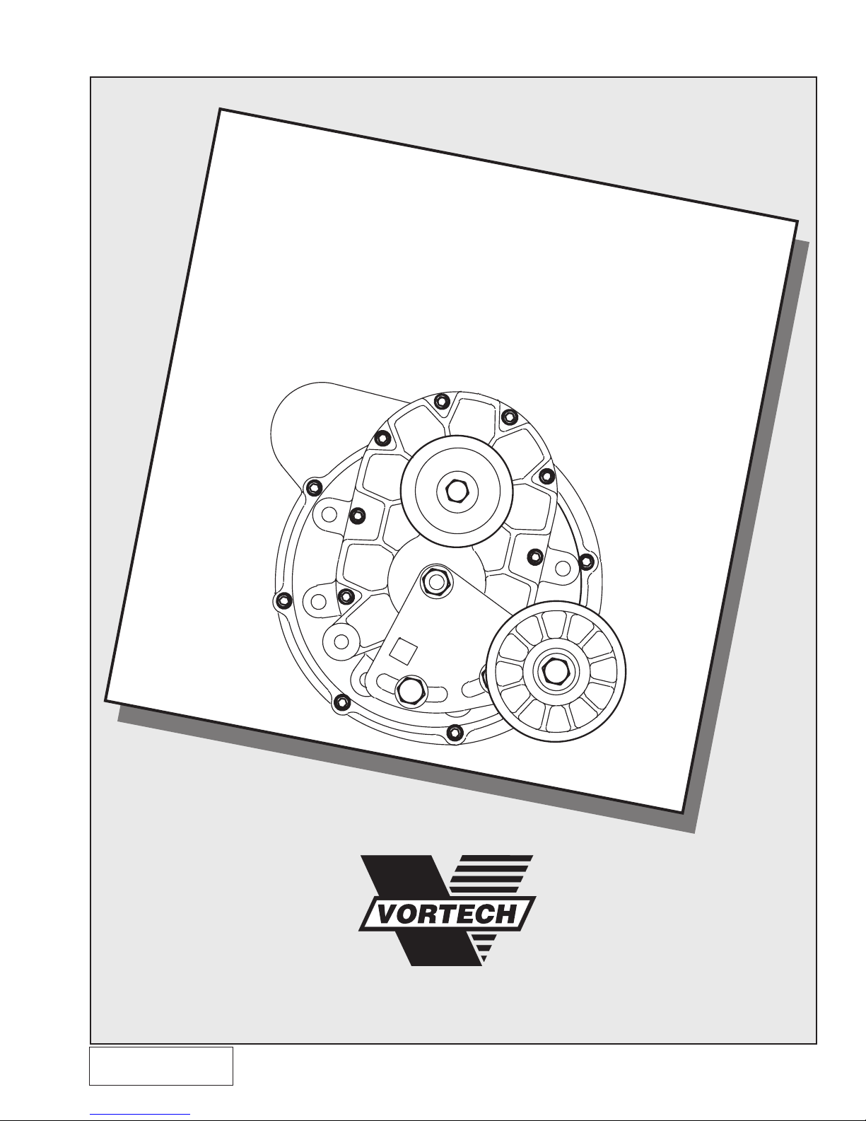
Ford 5.0L Mustang
®
Supercharger System
Installation Instructions
(CARB E0 # not applicable to Renegade Kit P/N: 4FA218-100/108)
50 State Smog Legal per CARB EO #D-213-17
1986-1993 MODEL YEARS
1650 PACIFIC AVENUE • CHANNEL ISLANDS, CA 93033-9901 • (805) 247-0226
FAX (805) 247-0669 • www.vortechsuperchargers.com • M-F 8:00 AM - 4:30 PM PST
P/N: 4FA020-010
© 2008 Vortech Engineering, LLC
All Rights Reserved, Intl. Copr. Secured
25MAR08 v4.0(86-93 5.0 Mus (4FA v4.0))
ENGINEERING, LLC
Page 2

FOREWORD
STOP
his manual provides information on the installation, maintenance and service of
the Vortech supercharger kit expressly designed for this vehicle. All information, il-
T
lustrations and specifications contained herein are based on the latest product information available at the time of this publication. Changes to the manual may be made
at any time without notice. Contact Vortech Engineering for any additional information
regarding this kit and any of these modifications at (805) 247-0228 8:00am-4:30pm PST.
Take note of the following before proceeding:
1. Proper installation of this supercharger kit requires general automotive
mechanic knowledge and experience. Please browse through each step
of this instruction manual prior to beginning the installation to determine if
you should refer the job to a professional installer/technician. Please contact your dealer or Vortech Engineering for possible installers in your area.
2. This product was designed for use on stock (un-modified, OEM) vehi-
cles. The PCM (computer), engine, transmission, drive axle ratios and tire O.D. must
be stock. If the vehicle or engine has been modified in any way, check with Vortech
prior to installation and use of this product.
3. Use only premium grade fuel with a minimum of 91 octane (R+M/2).
4. Always listen for any sign of detonation (knocking/pinging) and discontinue hard use
(no boost) until problem is resolved.
5. Vortech is not responsible for any clutch, transmission, drive-line or engine damage.
Exclusions from Vortech warranty coverage considerations include, but not limited to:
1. Neglect, abuse, lack of maintenance, abnormal operation or improper installation.
2. Continued operation with an impaired vehicle or sub-system.
3. The combined use of Vortech components with other modifications such as, but not
limited to, exhaust headers, aftermarket camshafts, nitrous oxide, third party PCM
programming or other such changes.
©2008 VORTECH ENGINEERING, LLC
All rights reserved. No part of this publication may be reproduced, transmitted, transcribed, or translated
into another language in any form, by any means without written permission of Vortech Engineering, LLC.
P/N: 4FA020-010
© 2008 Vortech Engineering, LLC
All Rights Reserved, Intl. Copr. Secured
25MAR08 v4.0(86-93 5.0 Mus (4FA v4.0))
ii
Page 3
TABLE OF CONTENTS
FOREWORD ......................................................................................................................................ii
TABLE OF CONTENTS .....................................................................................................................iii
IMPORTANT NOTICE ....................................................................................................................... iv
TOOL & SUPPLY REQUIREMENT ...................................................................................................v
PARTS LIST - 1986-1993 MUSTANG ..............................................................................................vi
PARTS LIST - 1993 MUSTANG COBRA .......................................................................................... vii
PARTS LIST - 1986-1993 HIGH-OUTPUT MUSTANG .....................................................................viii
PARTS LIST - 1986-1993 HIGH-OUTPUT MUSTANG (Internally Lubricated)................................ix
PARTS LIST - 1986-1993 RENEGADE MUSTANG .......................................................................... x
PARTS LIST - 1986-1993 SUPER HIGH-OUTPUT MUSTANG .......................................................xi
MSD IGNITION SYSTEM .................................................................................................................. xiii
1. PREPARATION/REMOVAL ..................................................................................................1
2. CRANKSHAFT PULLEY .......................................................................................................1
3. OIL DRAIN ............................................................................................................................2
4. OIL FEED LINE .....................................................................................................................2
5. FUEL MANAGEMENT UNIT ................................................................................................3
6. T-REX FUEL PUMP (High Output and Cobra Systems Only) ............................................4
7. MAIN BRACKET ASSEMBLY .............................................................................................. 7
8. SMOG PUMP HOSES .......................................................................................................... 8
9. RADIATOR HOSE ................................................................................................................9
10. ACCESSORY BELT TENSIONER MOUNTING BRACKET ..................................................9
11. SUPERCHARGER MOUNTING ...........................................................................................10
12. SUPERCHARGER DRIVE BELT ..........................................................................................10
13. AIR FILTER ASSEMBLY ..................................................................................................... 11
14. IGNITION/BOOST CONTROL INSTALLATION ...................................................................11
15. IGNITION/BOOST CONTROL UNIT OPERATION ...............................................................12
16. VORTECH BYPASS VALVE (High Output and Cobra Systems Only) ...............................13
© 2008 Vortech Engineering, Inc.
iii
All Rights Reserved, Intl. Copr. Secured
25MAR08 v4.0(86-93 5.0 Mus (4FA v4.0))
P/N: 4FA020-010
Page 4

NOTICE
This product is protected by state common law, copyright and/or patent. All
legal rights therein are reserved. The design, layout, dimensions, geometry, and
engineering features shown in this product are the exclusive property of Vortech
Engineering, Inc. This product may not be copied or duplicated in whole or part,
abstractly or fundamentally, intentionally or fortuitously, nor shall any design,
dimension, or other information be incorporated into any product or apparatus
without prior written consent of Vortech Engineering, LLC.
This Vortech 5.0 supercharger kit was designed for installation and use on Mass
Air Flow (MAF) equipped vehicles. The model years include 1988 California and
all 1989-1993 models. All other years not equipped with MAF systems (factory
or aftermarket) require the installation of a MAP sensor check valve assembly
(Vortech part number 4FD113-010). This allows proper function of early (1986-
1988) models equipped with speed density processors.
The factory water pump pulley may require removal and replacement with an
aftermarket unit for proper supercharger drive belt clearance. Also, an aftermarket
electric fan is recommended, although the factory mechanical fan may still be
retained with minor clearance modifications.
P/N: 4FA020-010
© 2008 Vortech Engineering, LLC
All Rights Reserved, Intl. Copr. Secured
25MAR08 v4.0(86-93 5.0 Mus (4FA v4.0))
RENEGADE 5.0L KIT
iv
Page 5
1986 - 1993
FORD 5.0L MUSTANG
Installation Instructions
50 State Smog Legal, as per CARB EO #D-213-17 (not applicable to P/N: 4FA218-100/108)
Congratulations on selecting the best performing and best backed automotive supercharger available
Before beginning this installation, please read through this entire instruction booklet and the Street
Supercharger System Owner's Manual (Race Owner's Manual for the Renegade kit) which includes the
Limited Warranty Program, the Warranty Registration form and return envelope.
1986-93 RENEGADE 5.0L MUSTANG KIT ONLY 4FA218-100/108
IMPORTANT NOTE: This kit does not supply any of the required fuel and ignition system support
assemblies. This kit was designed for racing/off-road use only.
IGNITION: An ignition amplification unit will be required above 10 psig manifold pressure. Crane HI-6/7 or MSD 6/7
are the most popular choices. A high output coil is also suggested. Spiral core, low resistance, suppression spark
plug wires will also be required. Vortech part number 5A002-005 is a 10.4mm premium wire set manufactured by
Taylor, with pre-cut lengths for the 5.0 Mustang.
FUEL SYSTEM: A high output fuel system will be required when horsepower levels reach approximately 400 or
above. Vortech produces a variety of fuel system combinations including the Maxflow Renegade system which
is a complete fuel system from the tank pickup to the fuel rails and will support up to 1000 hp (wiring harness is
included).
Vortech supercharger systems are performance improving devices. In most cases, increases in torque
of 30-35% and horsepower between 35-45% can be expected with the boost levels specified by Vortech
Engineering. This product is intended for use on healthy, well maintained engines. Installation on a worn-out
or damaged engine is not recommended and may result in failure of the engine as well as the supercharger.
Vortech Engineering is not responsible for engine damage.
Installation on new vehicles will not harm or adversely affect the break-in period so long as factory break-in
procedures are followed.
For best performance and continued durability, please take note of the following key points:
1. Use only premium grade fuel 91 octane or higher (R+M/2).
2. The engine must have stock compression ratio.
3. If the engine has been modified in any way, check with Vortech prior to using this product.
4. Always listen for any sign of detonation (pinging) and discontinue hard use (no boost) until problem is
resolved.
5. Perform an oil and filter change upon completion of this installation and prior to test driving your vehicle.
Thereafter, always use a high grade SF rated engine oil or a high quality synthetic, and change the
oil and filter at least every 3,000 miles. Never attempt to extend the oil change interval beyond 3,000
miles, regardless of oil manufacturer's claims as potential damage to the supercharger may result.
6. Before beginning installation, replace all spark plugs that are older than 1 year or 10,000 miles with
original heat range plugs as specified by the manufacturer and reset timing to factory specifications
(follow the procedures indicated within the factory repair manual and/or as indicated on the factory
underhood emissions tag). Do not use platinum spark plugs unless they are original equipment. Change
spark plugs every 15,000 miles and spark plug wires at least every 50,000 miles.
today... the VORTECH® supercharger!
TOOL & SUPPLY REQUIREMENT
• Factory repair manual
• Timing light
• 3/8" socket and drive set: SAE & metric
• 1/2" socket and drive set: SAE & metric
• 1/2" breaker bar and 4" extension
• 1/8" NPT tap, 3/8" NPT tap, 3/8-16 tap & handle
• Adjustable wrench
• Open end wrenches: 3/8", 7/16", 1/2", 9/16"
"Slimline" 19 mm - Snap-On #LTAM1719
• Center punch and a 5/8" tapered punch
• Ford springlock 3/8" fuel fitting disconnect tool
• 5 quarts SF rated quality engine oil, oil filter and wrench
If it has been 10,000 miles or more since your vehicle's last spark plug change,
then you will also need:
• Spark plug socket
• NEW spark plugs
• Large screwdriver or pry bar
• Flat #2 screwdriver
• Phillips #2 screwdriver
• Heavy grease
• Silicone sealer
• Drill motor
• 3/32", R or 5/16", 7/16" drill bits
v
© 2008 Vortech Engineering, Inc.
All Rights Reserved, Intl. Copr. Secured
25MAR08 v4.0(86-93 5.0 Mus (4FA v4.0))
P/N: 4FA020-010
Page 6
1986-1993 Mustang
®
Part No. 4FA218-010
ENGINEERING, LLC
PARTS LIST
IMPORTANT: Before beginning installation, verify that all parts are included in the
kit. Report any shortages or damaged parts immediately.
PART NUMBER DESCRIPTION QUANTITY
2A228-100 V-1 SUPERCHARGER ASSEMBLY 1
4FA111-032 SUPERCHARGER BELT 1
TENSIONER ASSEMBLY
7J012-092 12mm FLAT WASHERS 3
4FA011-032 BELT TENSIONER PLATE 1
7C012-050 12mm x 1.75" x 50mm BOLT 1
4FA016-150 SMOOTH PULLEY TENSIONER 1
2A017-010 IDLER PULLEY SPACER 1
7C012-020 12mm x 1.75" x 20mm BOLTS 2
7C012-022 12mm x 1.75" x 22mm THIN HEAD BOLT 1
7G010-175 12mm x 1.75" NUT 1
4FA112-010 AIR INTAKE ASSEMBLY 1
7S350-200 3-1/2" x 2" SLEEVE 1
4FA012-012 90° INTAKE ELBOW 1
4FA013-010 AIR CLEANER COVER 1
7J006-093 6mm WASHERS 2
7P375-097 3/8"NPT x 3/8" BARB 1
7S300-100 3" x 1" SLEEVE 1
7E010-046 #8 x 3/4" SHEET METAL SCREWS 2
8H040-010 AIR FILTER 1
7R002-056 #56 HOSE CLAMPS 2
7R002-052 #52 HOSE CLAMPS 2
7U035-000 3-1/2" x 12" FLEX HOSE 1
4FA112-020 AIR DISCHARGE ASSEMBLY 1
4FA012-020 DISCHARGE TUBE 1
7S275-200 2-3/4" x 2" SLEEVE 1
7S300-200 3" x 2" SLEEVE 1
7R002-044 #44 HOSE CLAMPS 2
7R002-048 #48 HOSE CLAMPS 2
4FA139-096 PCV BYPASS KIT 1
8H040-020 3/8" INLINE FILTER 1
7U375-052 3/8" VACUUM CAP 1
7U030-056 3/8" x 22" FUEL HOSE 1
4FA238-068 FMU (WITH LINES) 1
6Z110-111 12:1 BLACK FUEL MANAGEMENT UNIT 1
4FA145-010 MALE FUEL LINE ASSEMBLY 1
4FA145-020 FEMALE FUEL LINE ASSEMBLY 1
7U030-046 5/32" x 54" VACUUM LINE 1
7E010-046 #8 x 3/4" SHEET METAL SCREWS 2
7U100-055 6" NYLON TIE WRAPS 2
4FA130-036 OIL DRAIN ASSEMBLY 1
7R001-008 #8 STAINLESS HOSE CLAMPS 2
7P375-017 3/8"NPT x 1/2" STRAIGHT HOSE BARB 1
7U030-036 1/2" x 28" OIL DRAIN HOSE 1
PART NUMBER DESCRIPTION QUANTITY
4FA110-011 SPRING TENSIONER 1
MOUNTING ASSEMBLY
4FA010-011 TENSIONER MOUNTING BRACKET 1
7A375-100 3/8-16 x 1" BOLTS 2
7J375-044 3/8"SAE WASHERS 3
7F375-016 3/8-16 NUT 1
7A500-350 1/2-13 x 3-1/2" CARRIAGE BOLT 1
7F500-013 1/2-13 NUT 1
7J012-092 12mm FLAT WASHER 1
4FA114-023 RADIATOR HOSE ASSEMBLY 1
4FA014-011 RADIATOR PIPE 1
7R002-024 #24 HOSE CLAMPS 2
4FA111-021 MOUNTING BRACKET ASSEMBLY 1
4FA011-021 MOUNTING BRACKET 1
4FA010-034 MOUNTING PLATE 1
4FA015-015 ALTERNATOR STAY 1
4FA017-021 SMOG PUMP SPACER 1
7A375-625 3/8-16 x 6-1/4" BOLTS 2
7A375-700 3/8-16 x 7" BOLT 1
7A437-175 7/16-14 x 1-3/4" BOLT 1
7A375-175 3/8-16 x 1-3/4" BOLT 1
7A375-650 3/8-16 x 6-1/2" BOLT 1
7A375-200 3/8-16 x 2" BOLT 1
7A375-075 3/8-16 x 3/4" BOLT 1
7F375-016 3/8-16 NUTS 2
7A375-100 3/8-16 x 1" BOLTS 7
7K375-040 3/8"AN960 FLAT WASHERS 5
7J375-044 3/8"SAE WASHERS 10
7J012-092 12mm FLAT WASHER 1
4FA130-026 OIL FEED ASSEMBLY 1
7P525-067 .500" CRIMP FERRULES 2
7P250-066 #4 SWIVEL x 1/4" HOSE BARB FITTING 2
7P125-027 1/8"NPT STRAIGHT FITTING 1
7P125-103 1/8"NPT -4 x 45° MALE ELBOW 1
7U030-026 1/4" x 25" OIL FEED HOSE 1
7P250-121 3" NIPPLE 1
7P250-122 1/4" TEE 1
7P250-075 45° ELBOW 1
7P250-082 90° FLARE 1
4FA116-011 CRANK PULLEY ASSEMBLY 1
4FA016-011 6" CRANK PULLEY 1
7A375-208 3/8-16 x 2" CAP SCREWS 4
7J375-044 3/8"SAE WASHERS 4
2A046-527 BELT 1
P/N: 4FA020-010
© 2008 Vortech Engineering, LLC
All Rights Reserved, Intl. Copr. Secured
25MAR08 v4.0(86-93 5.0 Mus (4FA v4.0))
vi
Page 7
1993 Mustang Cobra
®
Part No. 4FA218-030SQ
ENGINEERING, LLC
PARTS LIST
IMPORTANT: Before beginning installation, verify that all parts are included in the
kit. Report any shortages or damaged parts immediately.
PART NUMBER DESCRIPTION QUANTITY
2E428-010 SUPERCHARGER ASSEMBLY 1
2E128-010 V-2 SUPERCHARGER 1
2A038-333 8-GR 3.33" SUPERCHARGER DRIVE PULLEY 1
8R101-002 8 AND 10-RIB PULLEY RETAINER ASSEMBLY 1
4FA111-021 MOUNTING BRACKET ASSEMBLY 1
4FA011-021 MOUNTING BRACKET 1
4FA010-034 MOUNTING PLATE 1
4FA015-015 ALTERNATOR STAY 1
4FA017-021 SMOG PUMP SPACER 1
7A375-625 3/8-16 x 6-1/4" BOLTS 2
7A375-700 3/8-16 x 7" BOLT 1
7A437-175 7/16-14 x 1-3/4" BOLT 1
7A375-175 3/8-16 x 1-3/4" BOLT 1
7A375-650 3/8-16 x 6-1/2" BOLT 1
7A375-200 3/8-16 x 2" BOLT 1
7A375-075 3/8-16 x 3/4" BOLT 1
7F375-016 3/8-16 NUTS 2
7A375-100 3/8-16 x 1" BOLTS 7
7K375-040 3/8"AN960 FLAT WASHERS 5
7J375-044 3/8"SAE WASHERS 10
7J012-092 12mm FLAT WASHER 1
4FA110-011 SPRING TENSIONER 1
MOUNTING ASSEMBLY
4FA010-011 TENSIONER MOUNTING BRACKET 1
7A375-100 3/8-16 x 1" BOLTS 2
7J375-044 3/8"SAE WASHERS 2
7F375-016 3/8-16 NUT 1
7A500-350 1/2-13 x 3-1/2" CARRIAGE BOLT 1
7F500-013 1/2-13 HEX NUT 1
7J012-092 12mm FLAT WASHER 1
4FA111-042 SUPERCHARGER 1
BELT TENSIONER ASSEMBLY
7J012-092 12mm FLAT WASHERS 3
4FA011-032 BELT TENSIONER PLATE 1
7C012-020 12mm x 1.75" x 20mm BOLTS 3
7G010-175 12mm x 1.75" NUT 1
4FA016-170 WIDE IDLER PULLEY 1
2A017-011 8-RIB IDLER SPACER 1
7C012-065 12mm x 1.75" x 65mm BOLT 1
4FA116-031 CRANK PULLEY ASSEMBLY 1
4FA018-022 8 GROOVE 4.75/6.87 CRANK PULLEY 1
7A375-178 3/8-16 x 1-3/4" BOLTS 4
7J375-044 3/8"SAE WASHERS 4
7L375-075 3/8" LOCK WASHERS 4
2A048-545 BELT 1
4FA238-078 FMU (WITH LINES) 1
6Z110-112 10:1 BLACK FUEL MANAGEMENT UNIT 1
4FA145-010 MALE FUEL ASSEMBLY 1
4FA145-020 FEMALE FUEL LINE ASSEMBLY 1
7U030-046 5/32" x 54" VACUUM LINE 1
7E010-046 #8 x 3/4" SHEET METAL SCREWS 2
7U100-055 6" NYLON TIE-WRAPS 2
4FA130-026 OIL FEED ASSEMBLY 1
7P525-067 .500" CRIMP FERRULES 2
7P250-066 #4 SWIVEL x 1/4" HOSE BARB FITTINGS 2
7P125-027 1/8" STRAIGHT FITTING 1
7P125-103 1/8"NPT -4 x 45° MALE ELBOW 1
7U030-026 1/4" x 25" OIL FEED HOSE 1
7P250-121 3" NIPPLE 1
7P250-122 1/4" TEE 1
7P250-075 45° ELBOW 1
7P250-082 90° FLARE 1
PART NUMBER DESCRIPTION QUANTITY
4FA130-036 OIL DRAIN ASSEMBLY 1
7R001-008 #8 STAINLESS HOSE CLAMPS 2
7P375-017 3/8"NPT x 1/2" STRAIGHT HOSE BARB 1
7U030-036 1/2" x 28" OIL DRAIN HOSE 1
4FA139-096 PCV BYPASS KIT 1
8H040-020 3/8" INLINE FILTER 1
7U375-052 3/8" VACUUM CAP 1
7U030-056 3/8" x 22" FUEL HOSE 1
4FA114-023 RADIATOR HOSE ASSEMBLY 1
4FA014-011 RADIATOR PIPE 1
7R002-024 #24 HOSE CLAMPS 2
5A101-001 STAND ALONE ASSEMBLY 1
7P156-082 5/32" TEE 1
5A002-002 FORD EFI WIRING HARNESS 1
5A001-001 STAND ALONE IGNITION RETARD 1
7U030-046 5/32" x 24" VACUUM LINE 1
4FA112-030 DISCHARGE ASSEMBLY 1
4FA012-030 ALUMINUM DISCHARGE TUBE 1
7S275-200 2-3/4" x 2" SLEEVE 1
7S300-200 3" x 2" SLEEVE 1
7R002-044 #44 HOSE CLAMPS 2
7R002-048 #48 HOSE CLAMPS 2
8D001-001 BYPASS VALVE 1
7P750-100 3/4"NPT x 1" STRAIGHT HOSE FITTING 1
7U134-145 1" x 4-1/2" HEATER HOSE 1
7U134-130 1" x 3" HEATER HOSE 1
7R002-016 #16 HOSE CLAMPS 4
7P156-082 5/32" TEE 1
7U030-046 5/32" x 24" VACUUM LINE 1
4FA112-015 AIR INTAKE ASSEMBLY 1
7S350-200 3-1/2" " 2" SLEEVE 1
4FA012-013 90° INTAKE ELBOW 1
4FA013-010 AIR CLEANER COVER 1
8H040-040 AIR FILTER 1
7J006-093 6mm WASHERS 2
7P375-097 3/8"NPT x 3/8" BARB 1
7S300-100 3" x 1" SLEEVE 1
7E010-046 #8 X 3/4" SHEET METAL SCREWS 2
7R002-056 #56 HOSE CLAMPS 2
7U035-000 3-1/2" x 12" FLEX HOSE 1
7R002-052 #52 HOSE CLAMPS 2
7P750-102 3/4"NPT x 1" 90° HOSE FITTING 1
8F201-265 T-REX® PUMP ASSEMBLY 1
7F008-032 8-32 HEX LOCK NUTS 8
7J008-001 #8 FLAT WASHERS 8
7P312-003 5/16" FEMALE FUEL CONNECTORS 2
7P312-001 FORD FUEL FITTING ADAPTER 1
7R004-002 17.0 STEPLESS CLAMPS 2
7R004-001 15.7 STEPLESS CLAMPS 3
7R001-004 #4 HOSE CLAMPS 2
7U314-001 #8 LORD MOUNTS 4
5W001-001 WIRE TAP 1
7U032-016 3/8" x 6" FUEL HOSE 1
7E010-050 #12 x 1/2" SHEET METAL SCREW 1
7U375-135 ADHESIVE MOUNTING PADS 4
7U100-055 6" NYLON TIE WRAPS 6
4FA020-030 T-REX PUMP TEMPLATE 1
8F101-200 T-REX WIRING ASSEMBLY 1
7U031-018 5/16" x 24 HP FUEL HOSE 1
8F002-265 90° T-REX INLINE FUEL PUMP 1
5W001-010 16-14GA FEMALE SLIDE 1
5W001-002 FUSE TAP 1
5W001-011 16-14GA EYELETS 2
7U100-044 4" NYLON TIE-WRAPS 4
7U031-018 5/16" x 30" MPI HOSE 1
vii
© 2008 Vortech Engineering, Inc.
All Rights Reserved, Intl. Copr. Secured
25MAR08 v4.0(86-93 5.0 Mus (4FA v4.0))
P/N: 4FA020-010
Page 8
1986-1993 High-Output Mustang
®
Part No. 4FA218-040SQ
ENGINEERING, LLC
PARTS LIST
IMPORTANT: Before beginning installation, verify that all parts are included in the
kit. Report any shortages or damaged parts immediately.
PART NUMBER DESCRIPTION QUANTITY
2E428-010 SUPERCHARGER ASSEMBLY 1
2E128-010 V-2 SUPERCHARGER 1
2E038-333 8-GR 3.33" SUPERCHARGER DRIVE PULLEY 1
8R101-002 8 & 10-RIB PULLEY RETAINER ASSEMBLY 1
4FA111-021 MOUNTING BRACKET ASSEMBLY 1
4FA011-021 MOUNTING BRACKET 1
4FA010-034 MOUNTING PLATE 1
4FA015-015 ALTERNATOR STAY 1
4FA017-021 SMOG PUMP SPACER 1
7A375-625 3/8-16 x 6-1/4" BOLTS 2
7A375-700 3/8-16 x 7" BOLT 1
7A437-175 7/16-14 x 1-3/4" BOLT 1
7A375-175 3/8-16 x 1-3/4" BOLT 1
7A375-650 3/8-16 x 6-1/2" BOLT 1
7A375-200 3/8-16 x 2" BOLT 1
7A375-075 3/8-16 x 3/4" BOLT 1
7F375-016 3/8-16 NUTS 2
7A375-100 3/8-16 x 1" BOLTS 7
7K375-040 3/8"AN960 FLAT WASHERS 5
7J375-044 3/8"SAE WASHERS 10
7J012-092 12mm FLAT WASHER 1
4FA110-011 SPRING TENSIONER 1
MOUNTING ASSEMBLY
4FA010-011 TENSIONER MOUNTING BRACKET 1
7A375-100 3/8-16 x 1" BOLTS 2
7J375-044 3/8"SAE WASHERS 2
7F375-016 3/8-16 NUT 1
7A500-350 1/2-13 x 3-1/2" CARRIAGE BOLT 1
7F500-013 1/2-13 HEX NUT 1
7J012-092 12mm FLAT WASHER 1
4FA111-042 SUPERCHARGER 1
BELT TENSIONER ASSEMBLY
7J012-092 12mm FLAT WASHERS 3
4FA011-032 BELT TENSIONER PLATE 1
7C012-020 12mm x 1.75" x 20mm BOLTS 3
7G010-175 12mm x 1.75" NUT 1
4FA016-170 WIDE IDLER PULLEY 1
2A017-011 8-RIB IDLER SPACER 1
7C012-065 12mm x 1.75" x 65mm BOLT 1
4FA116-041 CRANK PULLEY ASSEMBLY 1
4FA018-021 8-GR 6.0/6.87 CRANK PULLEY 1
7A375-178 3/8-16 x 1-3/4" BOLTS 4
7J375-044 3/8"SAE WASHERS 4
7L375-075 3/8" LOCK WASHERS 4
2A048-545 BELT 1
4FA238-068 FMU (WITH LINES) 1
6Z110-111 12:1 BLACK FUEL MANAGEMENT UNIT 1
4FA145-010 MALE FUEL ASSEMBLY 1
4FA145-020 FEMALE FUEL LINE ASSEMBLY 1
7U030-046 5/32" x 54" VACUUM LINE 1
7E010-046 #8 x 3/4" SHEET METAL SCREWS 2
7U100-055 6" NYLON TIE-WRAPS 2
4FA130-026 OIL FEED ASSEMBLY 1
7P525-067 .500" CRIMP FERRULES 2
7P250-066 #4 SWIVEL x 1/4" HOSE BARB FITTINGS 2
7P125-027 1/8" STRAIGHT FITTING 1
7P125-103 1/8"NPT -4 x 45° MALE ELBOW 1
7U030-026 1/4" x 25" OIL FEED HOSE 1
7P250-121 3" NIPPLE 1
7P250-122 1/4" TEE 1
7P250-075 45° ELBOW 1
7P250-082 90° FLARE 1
PART NUMBER DESCRIPTION QUANTITY
4FA130-036 OIL DRAIN ASSEMBLY 1
7R001-008 #8 STAINLESS HOSE CLAMPS 2
7P375-017 3/8"NPT x 1/2" STRAIGHT HOSE BARB 1
7U030-036 1/2" x 28" OIL DRAIN HOSE 1
4FA139-096 PCV BYPASS KIT 1
8H040-020 3/8" INLINE FILTER 1
7U375-052 3/8" VACUUM CAP 1
7U030-056 3/8" x 22" FUEL HOSE 1
4FA114-023 RADIATOR HOSE ASSEMBLY 1
4FA014-011 RADIATOR PIPE 1
7R002-024 #24 HOSE CLAMPS 2
5A101-001 STAND ALONE ASSEMBLY 1
7P156-082 5/32" TEE 1
5A002-002 FORD EFI WIRING HARNESS 1
5A001-001 STAND ALONE IGNITION RETARD 1
7U030-046 5/32" x 24" VACUUM LINE 1
4FA112-030 DISCHARGE ASSEMBLY 1
4FA012-030 ALUMINUM DISCHARGE TUBE 1
7S275-200 2-3/4" x 2" SLEEVE 1
7S300-200 3" x 2" SLEEVE 1
7R002-044 #44 HOSE CLAMPS 2
7R002-048 #48 HOSE CLAMPS 2
8D001-001 BYPASS VALVE 1
7P750-100 3/4"NPT x 1” STRAIGHT HOSE FITTING 1
7U134-145 1" x 4-1/2" HEATER HOSE 1
7U134-130 1" x 3" HEATER HOSE 1
7R002-016 #16 HOSE CLAMPS 4
7P156-082 5/32" TEE 1
7U030-046 5/32" x 24" VACUUM LINE 1
4FA112-015 AIR INTAKE ASSEMBLY 1
7S350-200 3-1/2" x 2" SLEEVE 1
4FA012-013 90° INTAKE ELBOW 1
4FA013-010 AIR CLEANER COVER 1
8H040-040 AIR FILTER 1
7J006-093 6mm WASHERS 2
7P375-097 3/8"NPT x 3/8" BARB 1
7S300-100 3" x 1" SLEEVE 1
7E010-046 #8 x 3/4" SHEET METAL SCREWS 2
7R002-056 #56 HOSE CLAMPS 2
7U035-000 3-1/2" x 12" FLEX HOSE 1
7R002-052 #52 HOSE CLAMPS 2
7P750-102 3/4"NPT x 1" 90° HOSE FITTING 1
8F201-265 T-REX® PUMP ASSEMBLY 1
7F008-032 8-32 HEX LOCK NUTS 8
7J008-001 #8 FLAT WASHERS 8
7P312-003 5/16" FEMALE FUEL CONNECTORS 2
7P312-001 FORD FUEL FITTING ADAPTER 1
7R004-002 17.0 STEPLESS CLAMPS 2
7R004-001 15.7 STEPLESS CLAMPS 3
7R001-004 #4 HOSE CLAMPS 2
7U314-001 #8 LORD MOUNTS 4
5W001-001 WIRE TAP 1
7U032-016 3/8" x 6" FUEL HOSE 1
7E010-050 #12 x 1/2" SHEET METAL SCREW 1
7U375-135 ADHESIVE MOUNTING PADS 4
7U100-055 6" NYLON TIE-WRAPS 6
4FA020-030 T-REX PUMP TEMPLATE 1
8F101-200 T-REX WIRING ASSEMBLY 1
7U031-018 5/16" x 24" HP FUEL HOSE 1
8F002-265 90° T-REX INLINE FUEL PUMP 1
5W001-010 16-14GA FEMALE SLIDE 1
5W001-002 FUSE TAP 1
5W001-011 16-14GA EYELETS 2
7U100-044 4" NYLON TIE-WRAPS 4
7U031-018 5/16" " 30" MPI HOSE 1
P/N: 4FA020-010
© 2008 Vortech Engineering, LLC
All Rights Reserved, Intl. Copr. Secured
25MAR08 v4.0(86-93 5.0 Mus (4FA v4.0))
viii
Page 9
1986-1993 High-Output Mustang
®
Part No. 4FA218-040L/048L
ENGINEERING, LLC
PARTS LIST
IMPORTANT: Before beginning installation, verify that all parts are included in the
kit. Report any shortages or damaged parts immediately.
PART NUMBER DESCRIPTION QUANTITY
2E328-010 V3-SI SUPERCHARGER ASSEMBLY 1
2E038-333 8-GR 3.33" SUPERCHARGER DRIVE PULLEY 1
8R101-002 8 & 10-RIB PULLEY RETAINER ASSEMBLY 1
4FA111-021 MOUNTING BRACKET ASSEMBLY 1
4FA011-021 MOUNTING BRACKET 1
4FA010-034 MOUNTING PLATE 1
4FA015-015 ALTERNATOR STAY 1
4FA017-021 SMOG PUMP SPACER 1
7A375-625 3/8-16 x 6-1/4" BOLTS 2
7A375-700 3/8-16 x 7" BOLT 1
7A437-175 7/16-14 x 1-3/4" BOLT 1
7A375-175 3/8-16 x 1-3/4" BOLT 1
7A375-650 3/8-16 x 6-1/2" BOLT 1
7A375-200 3/8-16 x 2" BOLT 1
7A375-075 3/8-16 x 3/4" BOLT 1
7F375-016 3/8-16 NUTS 2
7A375-100 3/8-16 x 1" BOLTS 7
7K375-040 3/8"AN960 FLAT WASHERS 5
7J375-044 3/8"SAE WASHERS 10
7J012-092 12mm FLAT WASHER 1
4FA110-011 SPRING TENSIONER 1
MOUNTING ASSEMBLY
4FA010-011 TENSIONER MOUNTING BRACKET 1
7A375-100 3/8-16 x 1" BOLTS 2
7J375-044 3/8"SAE WASHERS 2
7F375-016 3/8-16 NUT 1
7A500-350 1/2-13 x 3-1/2" CARRIAGE BOLT 1
7F500-013 1/2-13 HEX NUT 1
7J012-092 12mm FLAT WASHER 1
4FA111-042 SUPERCHARGER 1
BELT TENSIONER ASSEMBLY
7J012-092 12mm FLAT WASHERS 3
4FA011-032 BELT TENSIONER PLATE 1
7C012-020 12mm x 1.75" x 20mm BOLTS 3
7G010-175 12mm x 1.75" NUT 1
4FA016-170 WIDE IDLER PULLEY 1
2A017-011 8-RIB IDLER SPACER 1
7C012-065 12mm x 1.75" x 65mm BOLT 1
4FA116-041 CRANK PULLEY ASSEMBLY 1
4FA018-021 8-GR 6.0/6.87 CRANK PULLEY 1
7A375-178 3/8-16 x 1-3/4" BOLTS 4
7J375-044 3/8"SAE WASHERS 4
7L375-075 3/8" LOCK WASHERS 4
2A048-545 BELT 1
4FA238-068 FMU (WITH LINES) 1
6Z110-111 12:1 BLACK FUEL MANAGEMENT UNIT 1
4FA145-010 MALE FUEL ASSEMBLY 1
4FA145-020 FEMALE FUEL LINE ASSEMBLY 1
7U030-046 5/32" x 54" VACUUM LINE 1
7E010-046 #8 x 3/4" SHEET METAL SCREWS 2
7U100-055 6" NYLON TIE-WRAPS 2
PART NUMBER DESCRIPTION QUANTITY
4FA139-096 PCV BYPASS KIT 1
8H040-020 3/8" INLINE FILTER 1
7U375-052 3/8" VACUUM CAP 1
7U030-056 3/8" x 22" FUEL HOSE 1
4FA114-023 RADIATOR HOSE ASSEMBLY 1
4FA014-011 RADIATOR PIPE 1
7R002-024 #24 HOSE CLAMPS 2
5A101-001 STAND ALONE ASSEMBLY 1
7P156-082 5/32" TEE 1
5A002-002 FORD EFI WIRING HARNESS 1
5A001-001 STAND ALONE IGNITION RETARD 1
7U030-046 5/32" x 24" VACUUM LINE 1
4FA112-030 DISCHARGE ASSEMBLY 1
4FA012-030 ALUMINUM DISCHARGE TUBE 1
7S275-200 2-3/4" x 2" SLEEVE 1
7S300-200 3" x 2" SLEEVE 1
7R002-044 #44 HOSE CLAMPS 2
7R002-048 #48 HOSE CLAMPS 2
8D001-001 BYPASS VALVE 1
7P750-100 3/4"NPT x 1” STRAIGHT HOSE FITTING 1
7U134-145 1" x 4-1/2" HEATER HOSE 1
7U134-130 1" x 3" HEATER HOSE 1
7R002-016 #16 HOSE CLAMPS 4
7P156-082 5/32" TEE 1
7U030-046 5/32" x 24" VACUUM LINE 1
4FA112-015 AIR INTAKE ASSEMBLY 1
7S350-200 3-1/2" x 2" SLEEVE 1
4FA012-013 90° INTAKE ELBOW 1
4FA013-010 AIR CLEANER COVER 1
8H040-040 AIR FILTER 1
7J006-093 6mm WASHERS 2
7P375-097 3/8"NPT x 3/8" BARB 1
7S300-100 3" x 1" SLEEVE 1
7E010-046 #8 x 3/4" SHEET METAL SCREWS 2
7R002-056 #56 HOSE CLAMPS 2
7U035-000 3-1/2" x 12" FLEX HOSE 1
7R002-052 #52 HOSE CLAMPS 2
7P750-102 3/4"NPT x 1" 90° HOSE FITTING 1
8F201-265 T-REX® PUMP ASSEMBLY 1
7F008-032 8-32 HEX LOCK NUTS 8
7J008-001 #8 FLAT WASHERS 8
7P312-003 5/16" FEMALE FUEL CONNECTORS 2
7P312-001 FORD FUEL FITTING ADAPTER 1
7R004-002 17.0 STEPLESS CLAMPS 2
7R004-001 15.7 STEPLESS CLAMPS 3
7R001-004 #4 HOSE CLAMPS 2
7U314-001 #8 LORD MOUNTS 4
5W001-001 WIRE TAP 1
7U032-016 3/8" x 6" FUEL HOSE 1
7E010-050 #12 x 1/2" SHEET METAL SCREW 1
7U375-135 ADHESIVE MOUNTING PADS 4
7U100-055 6" NYLON TIE-WRAPS 6
4FA020-030 T-REX PUMP TEMPLATE 1
8F101-200 T-REX WIRING ASSEMBLY 1
7U031-018 5/16" x 24" HP FUEL HOSE 1
8F002-265 90° T-REX INLINE FUEL PUMP 1
5W001-010 16-14GA FEMALE SLIDE 1
5W001-002 FUSE TAP 1
5W001-011 16-14GA EYELETS 2
7U100-044 4" NYLON TIE-WRAPS 4
7U031-018 5/16" " 30" MPI HOSE 1
009035 LUBE ASSY 1
© 2008 Vortech Engineering, Inc.
ix
All Rights Reserved, Intl. Copr. Secured
25MAR08 v4.0(86-93 5.0 Mus (4FA v4.0))
P/N: 4FA020-010
Page 10
1986-1993 Renegade Mustang
®
Part No. 4FA218-100
ENGINEERING, LLC
PARTS LIST
IMPORTANT: Before beginning installation, verify that all parts are included in the
kit. Report any shortages or damaged parts immediately.
PART NUMBER DESCRIPTION QUANTITY
2A258-010 SUPERCHARGER ASSEMBLY 1
4FA111-021 MOUNTING BRACKET ASSEMBLY 1
4FA011-021 MOUNTING BRACKET 1
4FA010-034 MOUNTING PLATE 1
4FA015-015 ALTERNATOR STAY 1
4FA017-021 SMOG PUMP SPACER 1
7A375-625 3/8-16 x 6-1/4" BOLTS 2
7A375-700 3/8-16 x 7" BOLT 1
7A437-175 7/16-14 x 1-3/4" BOLT 1
7A375-175 3/8-16 x 1-3/4" BOLT 1
7A375-650 3/8-16 " 6-1/2" BOLT 1
7A375-200 3/8-16 x 2" BOLT 1
7A375-075 3/8-16 x 3/4" BOLT 1
7F375-016 3/8-16 NUTS 2
7A375-100 3/8-16 x 1" BOLTS 7
7K375-040 3/8"AN960 FLAT WASHERS 5
7J375-044 3/8"SAE WASHERS 10
7J012-092 12mm FLAT WASHER 1
4FA110-011 SPRING TENSIONER 1
MOUNTING ASSEMBLY
4FA010-011 TENSIONER MOUNTING BRACKET 1
7A375-100 3/8-16 x 1" BOLTS 2
7J375-044 3/8"SAE WASHERS 2
7F375-016 3/8-16 NUT 1
7A500-350 1/2-13 x 3-1/2" CARRIAGE BOLT 1
7F500-013 1/2-13 HEX NUT 1
7J012-092 12mm FLAT WASHER 1
4FA130-026 OIL FEED ASSEMBLY 1
7P525-067 .500" CRIMP FERRULES 2
7P250-066 #4 SWIVEL x 1/4" HOSE BARB FITTINGS 2
7P125-027 1/8" STRAIGHT FITTING 1
7P125-103 1/8"NPT -4 x 45° MALE ELBOW 1
7U030-026 1/4" x 25" OIL FEED HOSE 1
7P250-121 3" NIPPLE 1
7P250-122 1/4" TEE 1
7P250-075 45° ELBOW 1
7P250-082 90° FLARE 1
4FA130-036 OIL DRAIN ASSEMBLY 1
7R001-008 #8 STAINLESS HOSE CLAMPS 2
7P375-017 3/8"NPT x 1/2" STRAIGHT HOSE BARB 1
7U030-036 1/2” x 28" OIL DRAIN HOSE 1
4FA112-070 AIR INLET ASSEMBLY 1
4FA112-060 4" INLET DUCT WITH BUNG 1
7S400-200 4" x 2" SLEEVE 2
7R002-064 #64 HOSE CLAMP 4
7S00-325 2" x 3.25" SLEEVE 1
7R002-032 #32 HOSE CLAMP 2
4FA114-023 RADIATOR HOSE ASSEMBLY 1
4FA014-011 RADIATOR PIPE 1
7R002-024 #24 HOSE CLAMPS 2
PART NUMBER DESCRIPTION QUANTITY
8E018-300 PULLEY PACKAGE, RENEGADE 1
2A038-300 SUPERCHARGER PULLEY 3" 8 GROOVE 1
7A375-158 3/8-16 x 1.5" SOC HD 4
7K375-040 3/8" WASHER 4
7L375-075 3/8" LOCK WASHER 4
4FA018-027 8" 8-GV CRANK PULLEY 1
8R101-002 PULLEY RETAINER ASSY, 8-RIB 1
4FA1110042 S/C BELT TENSIONER ASSY, H.O. 1
2A048-565 BELT 1
4FA212-050 V-7 DISCHARGE WITH BYPASS 1
7S003-200 3" x 2" SLEEVE 1
7S300-275 REDUCER, 3.00" - 2.75" 1
7R002-052 #52 HOSE CLAMP 2
7R002-048 #48 HOSE CLAMP 2
8D103-001 MAXFLOW MONDO BYPASS VALVE 1
4FA012-041 DISCHARGE TUBE, RACE 1
7S325-200 3.25" x 2" SLEEVE 1
P/N: 4FA020-010
© 2008 Vortech Engineering, LLC
All Rights Reserved, Intl. Copr. Secured
25MAR08 v4.0(86-93 5.0 Mus (4FA v4.0))
x
Page 11
1986-1993 5.0 S.H.O. V-7 Mustang
®
Part No. 4FA218-200
ENGINEERING, LLC
PARTS LIST
IMPORTANT: Before beginning installation, verify that all parts are included in the
kit. Report any shortages or damaged parts immediately.
PART NUMBER DESCRIPTION QUANTITY
2A258-020 SUPERCHARGER, YSI, 3.33" 10-RIB 1
4FA111-031 MNTG BRCKT ASSY, S.H.O. 1
4FA010-045 ALUM. MTG PLATE, BILLET 5.0 1
4FA011-021 MOUNTING BRACKET 1
4FA015-015 ALTERNATOR STAY-PLATED 1
4FA017-021 SPACER, SMOG PUMP 1
7A375-075 3/8-16 x 3/4" GR5 HXHD 1
7A375-100 3/8-16 x G5 HXHD PLT 8
7A375-175 3/8-16 x 1-3/4 HXHD 1
7A375-200 3/8-16 x 2 GR5 PLTD 1
7A375-625 3/8-16 x 6-1/4 HXHD 2
7A375-675 3/8-16 x 6.75" HXHD GR8 ZINC 1
7A375-751 3/8-16 x 7.5" HXHD GR8 ZINC 1
7A437-175 7/16-14 x 1-3/4" HXHD 1
7F375-016 3/8-16 HX NUT 2
7J012-092 12mm WASHER, FLAT 1
7J375-044 3/8"SAE WASHER, PLTD 6
7K375-040 3/8"AN960 FLAT WASHER 12
4FA116-150 CRK PLY ASSY, 10RIB V-7 KIT 1
7B375-150 3/8-24 x 1-1/2" GR8 HX 1
7A375-178 3/8-16 x 1-3/4" HXHD G8 4
7J375-044 3/8"SAE WASHER, PLTD 4
7L375-075 3/8 LOCK WASHER 4
2A041-545 BELT, CUSTOM 545, 10-RIB SERP 1
4FA018-023 4.75/6.87 10-GR CKPLY 1
4FA017-051 FAN SPACER 5.0" 1
7U313-021 5/16-24 x 1.5" STUD 4
7F312-021 5/16-24 NUT 4
7J312-000 5/16" FLAT WASHER-SAE 4
4FA238-068 FMU 12:1 W/LINES 1
6Z110-111 FUEL MGMT UNIT, 12:1 1
4FA145-010 FUEL LINE 5.0-MALE 1
4FA145-020 FUEL LINE 5.0-FEMALE 1
7U030-046 5/32" VACUUM LINE 4.5
7U100-055 TIE-WRAP, 6" NYLON 2
4FA130-027 OIL FEED ASSEMBLY 1
7P125-027 FITTING, STRGT, 1/8"NPT 1
7P125-103 -4 x 45° FITTING 1
70000 INSPECTOR NUMBER 0
7P250-121 1/4"NPT STEEL NIPPLE 1
7P250-122 1/4" PIPE THRD AN917 TEE 1
7P250-075 1/4"NPT 45° STRT ELBOW 1
7P250-082 1/4"NPT x -4 90° FITTING 1
4FA145-030 OIL FEED HOSE ASSY 5.0 86-93 1
4FA130-036 OIL DRAIN ASSEMBLY 1
7U030-036 1/2" OIL DRAIN HOSE x 28" 1
7P375-017 3/8"NPT x 1/2" HOSE BARB 1
7R001-008 #8 STNLS HOSE CLAMP 2
4FA114-011 RADIATOR HOSE ASSEMBLY 1
4FA014-011 RADIATOR PIPE-POLISHED 1
7R002-024 #24 GOLDSEAL HOSE CLAMP 2
PART NUMBER DESCRIPTION QUANTITY
4FA112-090 DISCH. ASSY S.H.O. V-7 KIT-SATIN 1
4FA012-041 DISCHARGE TUBE, RACE 1
7S300-200 3" x 2" SLEEVE 1
7S325-200 3.25" x 2" SLEEVE 1
7R002-052 #52 GOLDSEAL HOSE CLAMP 2
7R002-048 #48 GOLDSEAL HOSE CLAMP 2
8D204-001 MAXFLOW RACE BYPASS 1
7P250-030 1/4" BARBED MALE TEE 1
7U030-030 1/4" VACUUM HOSE 2'
4FA112-080 4" AIR INLET ASSY, 5.0 S.H.O. 1
4FA112-080 4" ELBOW, W/BUNG 1
7S400-200 4" x 2" SLEEVE 1
7R002-064 #64 GOLDSEAL HOSE CLAMP 2
7S175-400 Ø1.75" x 4" SLEEVE 1
7R002-028 #28 GOLDSEAL HOSE CLAMP 2
7U030-056 3/8" PCV HOSE x 1.5" 1
7P250-047 1/4"NPT TO 3/8" BARB 90° 1
8F201-265 T-REX PMP ASSY, 86-93 5.0 1
5W001-001 WIRE TAP 1
5W001-002 FUSE TAP 1
5W001-040 12-10GA FEMALE SLIDE 1
5W001-042 12-10GA 3/16" RING TERMINAL 2
4FA020-030 TEMPLATE, T-REX PUMP 0
7E010-050 #12 x 1/2" SHEET METAL SCREW 1
7F008-032 8-32 HEX LOCK NUT 8
7J008-001 #8 FLAT WASHER 8
7P312-001 ADAPTER, FUEL FITTING 1
7P312-003 5/16" FEMALE FUEL 2
7R001-004 #4 HOSE CLAMP 2
7R004-003 14.5 STEPLESS CLAMP 3
7R004-002 17.0 STEPLESS CLAMP 2
7U100-044 TIE-WRAP, 4" NYLON 4
7U100-055 TIE-WRAP, 6" NYLON 6
7U031-018 5/16" FUEL HOSE HI-PSR x 2" 1
7U031-018 5/16" FUEL HOSE HI-PSR x 2.5" 2.1
7U032-016 3/8" FUEL HOSE HI-PSR x 6" .1
7U314-001 #8 LORD MOUNTS 4
7U375-135 ADHES MTNG PAD 4
8F002-265 T-REX FUEL PUMP-INLINE 90° 1
8F101-200 T-REX WIRING ASSY MUSTANG 1
5W001-014 FUSE HOLDER 10GA WIRE 1
5W001-015 FUSE, BLADE TYPE 20AMP 1
5W001-019 SOLDERLESS CONNECTOR 10-12 1
8F110-011 SPRING TENS. MOUNT 1
4FA010-011 TENS. BRKT.-MACH 1
7A375-100 3/8-16 x 1" G5 HXHD PLT 2
7A500-350 1/2-13 x 3-1/2" CARRIAGE 1
7F375-016 3/8-16 HEX NUT 1
7F500-013 1/2-13 HEX NUT 1
7J012--92 12mm WASHER, FLAT 1
7J375-044 3/8"SAE WASHER, PLTD 3
© 2008 Vortech Engineering, Inc.
xi
All Rights Reserved, Intl. Copr. Secured
25MAR08 v4.0(86-93 5.0 Mus (4FA v4.0))
P/N: 4FA020-010
Page 12
1986-1993 5.0 S.H.O. V-7 Mustang, cont'd.
®
Part No. 4FA218-200
ENGINEERING, LLC
PARTS LIST
IMPORTANT: Before beginning installation, verify that all parts are included in the
kit. Report any shortages or damaged parts immediately.
PART NUMBER DESCRIPTION QUANTITY
4FA111-062 S/C BELT TENSNR ASSY, S.H.O. 1
4FA011-042 BELT TENSIONER PLATE 1
2A017-012 SPACER, 10-RIB IDLER 1
7C012-065 12mm x 1.75" x 20mm PLD 3
7C012-065 12mm x 1.75" x 65mm HX 1
7G010-175 12mm x 1.75" NUT 1
7J012-092 12mm WASHER, FLAT 3
4FA016-171 DUST COVER (WIDE IDLER) 1
4FA016-170 IDLER PULLEY, WIDE 1
8H140-000 FENDER MOUNT MAF KIT 86-93 1
8H040-030 AIR FILTER 3-1/2" CYL 1
7S350-300 3-1/2" x 3" SLEEVE 1
7S350-200 3-1/2" x 2" SLEEVE 1
4FA012-012 INTAKE ELBOW, 90° 2
7R002-056 #56 GOLDSEAL HOSE CLP 4
7C060-016 M6 x 1.00" x 16 HXHD 3
7J006-093 6mm WASHER, PLATED 3
5W001-007 3/16" HEAT-SHRINK TUBE .666'
5W018-020 18GA STRD WIRE BLK 1'
5W018-010 18GA STRD WIRE RED 1'
5W018-060 18GA STRD WIRE ORANGE 1'
5W018-070 18GA STRD WIRE GREEN 1'
4FA020-020 TEMPLATE, MASS AIR 0
7U035-001 3-1/2" FLEX HOSE 1
2A046-888 BELT, K060888 1
P/N: 4FA020-010
© 2008 Vortech Engineering, LLC
All Rights Reserved, Intl. Copr. Secured
25MAR08 v4.0(86-93 5.0 Mus (4FA v4.0))
xii
Page 13

SPECIAL NOTICE CONCERNING THE
MSD IGNITION SYSTEM
The MSD Boost Timing Master, manufactured by Autotronic
Controls Corporation, that may be included in this kit,
is serviced exclusively by the manufacturer. Autotronic
Controls Corporation warrants this product to be free from
defects in material and workmanship under normal use
and if properly installed for a period of one (1) year from
the date of purchase. In case of malfunction, this unit will
be repaired free of charge according to the terms of the
warranty. If found to be defective as mentioned above, it
will be repaired or replaced if returned prepaid along with
proof of purchase. This shall constitute the sole remedy of
the purchaser and the sole liability of Autotronic Controls
Corporation and/or Vortech Engineering, Inc. To the extent
permitted by law, the foregoing is exclusive and in lieu of all
other warranties or representations whether expressed or
implied, including any implied warranty of merchantability
or fitness. In no event shall Autotronic Controls Corporation
and/or Vortech Engineering, Inc. be liable for labor charges,
special or consequential damages.
When returning this unit for service, proof of purchase must
be supplied for warranty verification. After the warranty period
has expired, repair service is charged between a minimum
and maximum charge. In either case, please send the unit
pre-paid with proof of purchase to the attention of:
Autotronic Controls Corporation
Customer Service Department
12120 Esther Lama
Suite #114
El Paso, Texas, 79936
Phone: (915) 855-7123
Fax: (915) 857-3344
www.msdignition.com
The repaired unit will be returned as soon as possible after
receipt, COD for any charges. Be sure you include a detailed
account of any problems experienced, the type of vehicle
and any modifications.
Should you have any technical or installation questions
regarding this unit, contact Vortech Engineering, Inc. directly
at (805) 247-0226.
xiii
© 2008 Vortech Engineering, Inc.
All Rights Reserved, Intl. Copr. Secured
25MAR08 v4.0(86-93 5.0 Mus (4FA v4.0))
P/N: 4FA020-010
Page 14
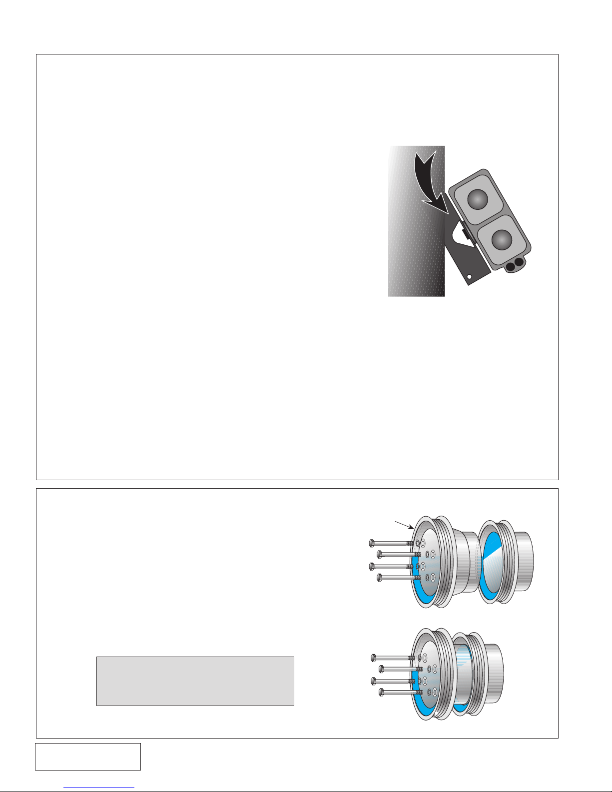
NEW ADDITIONAL PULLEY
BOLTS: 3/8-16x2"
RENEGADE/HIGH-OUTPUT PULLEY
STANDARD PULLEY
HIGH-OUTPUT BOLTS:
3/8-16x2-3/4"
RENEGADE BOLTS:
3/8-16x1-1/2"
1. PREPARATION/REMOVAL
FRAME
RELOCATED
EVAPORATIVE
CANISTER ASSY.
A. Disconnect the battery negative cable.
B. Remove the accessory drive belt. Super High-Output
(S.H.O.) V-7 installations also require removal of the shroud
and fan from the vehicle.
C. Remove the radiator fan assembly and carefully place it
in the fan shroud, out of the way.
D. Remove all components that lead to the throttle body
including air filter assembly, rubber bellows, mass air
flow (MAF) sensor and bracket with rubber mounts and
resonator from inner fender. Separate the MAF sensor
from the mounting bracket and set aside.
E. The ground wire attached to the radiator support must be
rerouted so as to pass through the hole behind the right
headlight and secured from the front. Make sure to clean
away any paint that would insulate the end of the ground
wire from the grounding point on the vehicle.
F. Drain approximately one gallon of coolant. Remove upper
radiator hose and set aside.
G. Remove the crankcase vent tube from between oil filter
and throttle body.
H. Remove belt tensioner assembly.
I. Unplug wire connections and remove alternator assembly
(make sure the battery is disconnected).
J. Remove brace from between the smog pump and front
engine cover.
K. Disconnect hoses and remove smog pump and cast
mounting bracket.
L. Relocate the evaporative canister forward (at a slight angle)
by using only the front bolt in the bracket rear hole. (See
Fig. 1-a.)
Fig. 1-a
2. CRANKSHAFT PULLEY
A. Remove crankshaft pulley.
B. For the standard output system, place the
cast Vortech crank pulley into the stock
pulley as shown and secure with the longer
bolts and washers as a unit.
P/N: 4FA020-010
© 2008 Vortech Engineering, LLC
All Rights Reserved, Intl. Copr. Secured
25MAR08 v4.0(86-93 5.0 Mus (4FA v4.0))
C. For the Vortech High Output, S.H.O. or
V -7 Renegade system, remove the factory
crank pulley and replace with the new
high output crank pulley; secure with the
supplied bolts and washers.
NOTE: Tighten bolts progressively
and evenly in a crisscross
pattern so that pulleys align
properly.
Fig. 2-a
Fig. 2-b
1
Page 15
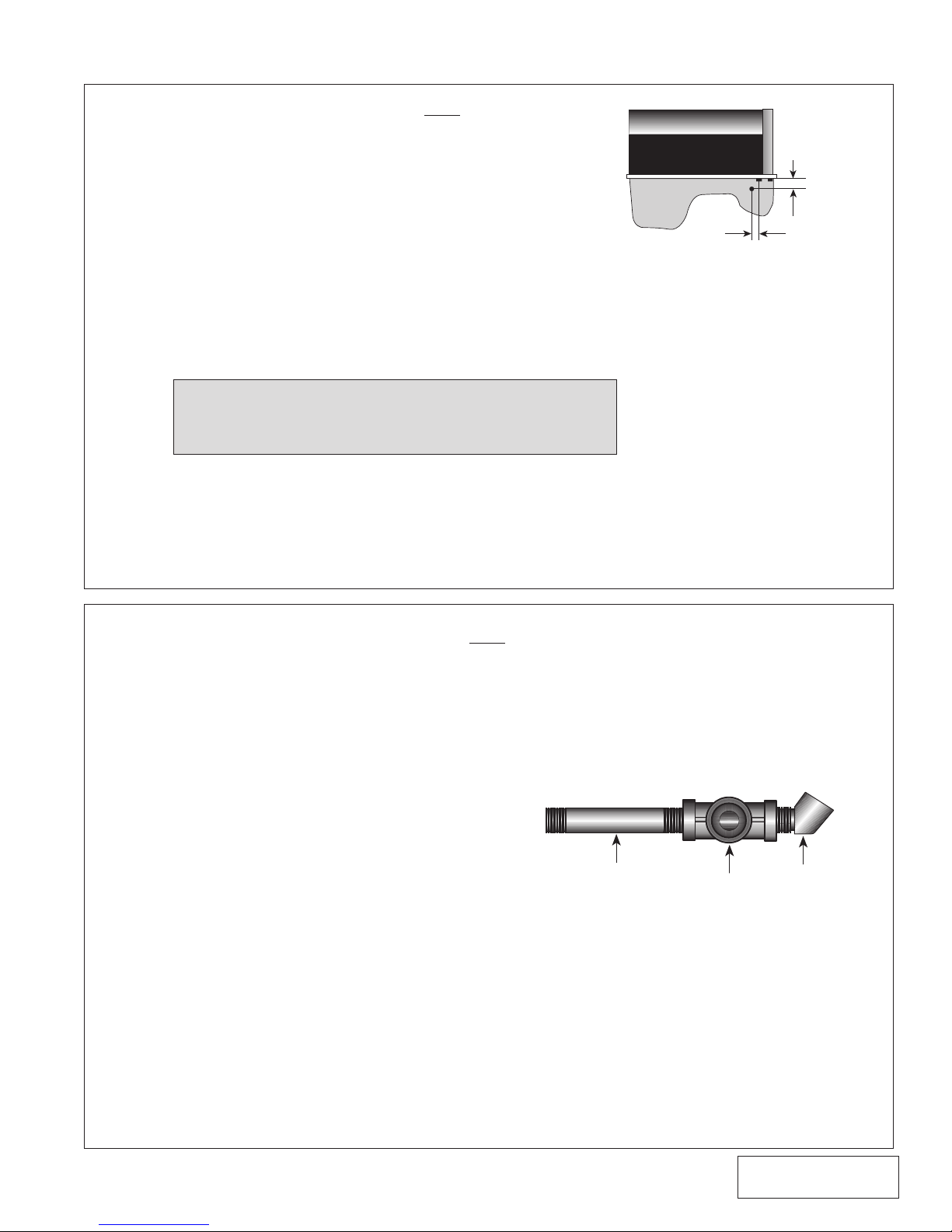
3. OIL DRAIN (Engine oil fed kits only. V3 kits, skip
ENGINE BLOCK
1/2” REAR FROM FIRST BOLT ON SIDE
FRONT
1-3/4”
BELOW
PAN LIP
3” NIPPLE
1/4” TEE
45°ELBOW
ahead to section 5)
A. To provide an oil drain for the supercharger, it is necessary
to make a hole in the oil pan. Locate and mark hole per
diagram. It is best to punch the hole rather than drill.
B. Remove paint around the hole area.
C. Use a small center punch to perforate the pan and expand
hole. Switch to a larger diameter punch and expand the hole
further to approximately 9/16" diameter. Most punches
are made from hexagon material and may be placed in a
socket with an extension to make this procedure easier.
D. Tap the hole with a 3/8" NPT tap approximately1/4" deep.
Pack the flutes of the tap with heavy grease to hold chips.
Use a small magnet to check for any stray chips.
NOTE: This method of rolling over the lip of the hole and
tapping it works very well if carefully done and
should cause no problems.
E. Thoroughly clean the threaded area. Apply a small amount
of silicone sealer to the new threads. Apply more sealer
to the 3/8" NPT hose fitting and secure in hole. Make sure
a seal is formed all around the fitting.
F. Drain the engine oil and change the filter.
Fig. 3-a
4. OIL FEED LINE (Engine oil fed kits only.
V3 kits, skip ahead to section 5)
A. Remove the oil pressure sender and mounting
boss fitting from the engine. These are found
on the engine's left side just ahead of the oil
filter.
B. Thread the supplied 3" x 1/4" NPT nipple into the
block using engine oil on the threads. Pipe tape,
paste or other sealant is not recommended as it
might loosen and cause blockage of the oil feed
orofice, resulting in supercharger failure.
C. Thread the supplied 1/4" female TEE into the
nipple. Rotate the TEE so that the center leg
points toward the front of the vehicle. Thread
the 45° elbow into the leg of the TEE pointing
toward the side of the vehicle.
D. Install the factory sending unit into the 45°
elbow.
E. Thread the supplied flare fitting into the
remaining leg of the TEE.
F. Connect the red oil feed line to the fitting at the
pressure sender and route it behind the A/C
mounting plate to the supercharger location.
Cover the end of the hose with a clean plastic
bag. Connect the line to the supercharger with
the flare fitting provided.
Fig. 4-a
© 2008 Vortech Engineering, Inc.
2
All Rights Reserved, Intl. Copr. Secured
25MAR08 v4.0(86-93 5.0 Mus (4FA v4.0))
P/N: 4FA020-010
Page 16
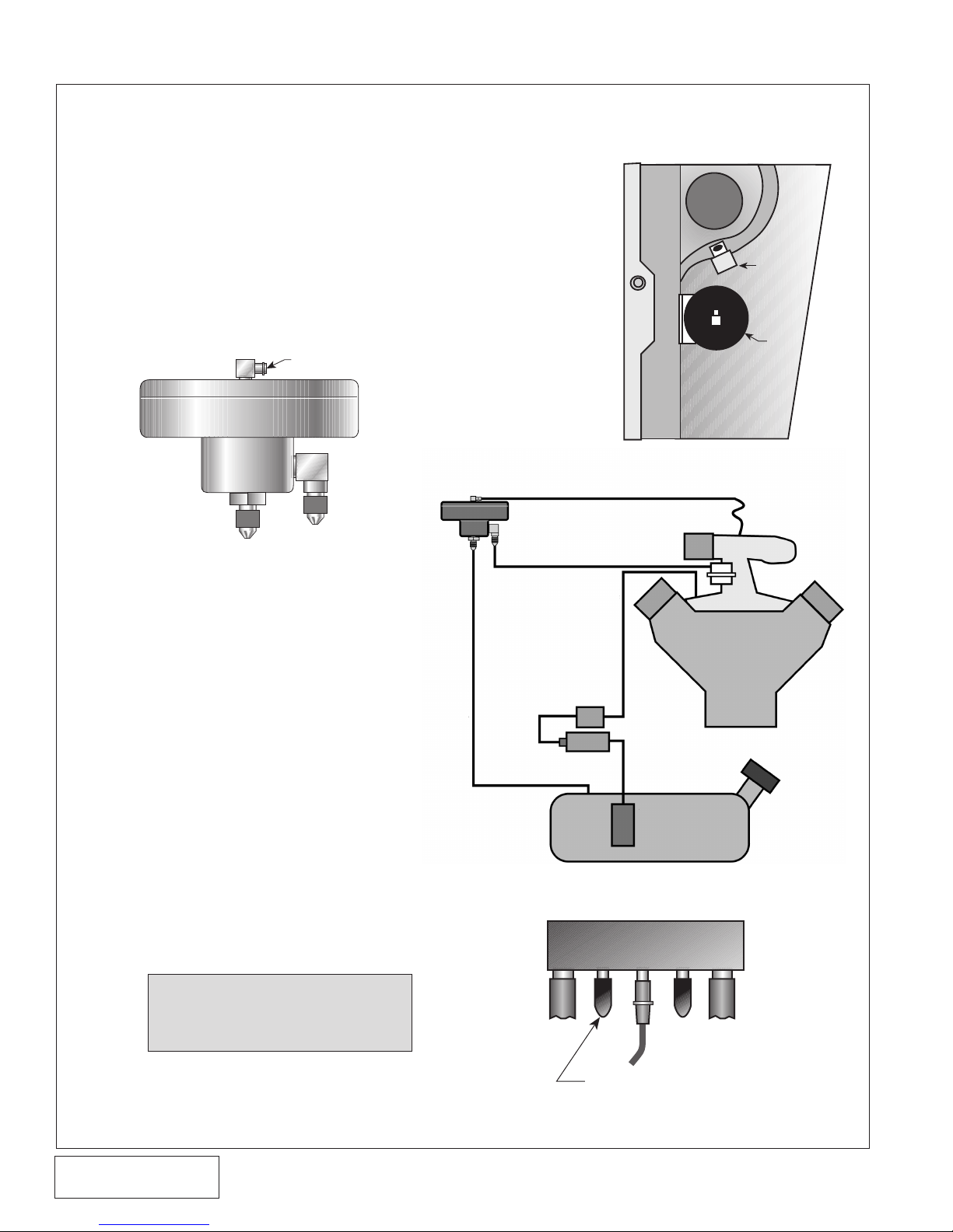
5. FUEL MANAGEMENT UNIT (skip this step for Renegade applications)
FMU
RELAY
SHOCK TOWER
CONNECT TO
MANIFOLD
VACUUM/PRESSURE
INLET
FUEL LINE
FROM
STOCK
REGULATOR
OUTLET
(FUEL FROM HERE
RETURNS TO TANK)
B/R S/C
REMOVE VACUUM CAP
AND ATTACH FMU LINE HERE
A. Relocate the relay using the stock screw.
B. Locate the fuel management unit against the inner
fender panel ahead of the shock tower about an inch
from the top. Drill holes and secure with the sheet
metal screws provided. (See Fig. 5-a.)
C. Disconnect the fuel rail return line at the rubber hose
on the engine's lower right side with a 3/8" spring
lock disconnect tool. The return line does not have
the pressure test fitting on it.
Fig. 5-a
D. Connect the Fuel Management
Unit (FMU) input hose (the hose
that goes to the 90° fitting on the
side of the FMU) to the return
line coming from the fuel rail
regulator as shown in Fig. 5-b.
E. Connect the unit’s return hose
(that connects to the center
fitting) to the stock return
hose.
F. Secure the fuel lines away from
the exhaust header with the tie
wraps provided.
G. Connect the top fitting on the
FMU to the multi-branch fitting
located on the driver's side
firewall using the supplied
5/32" hose. Use the port with
the "B/R" designation. (See Fig.
5-c.)
NOTE: Add on inline fuel pump
with unit provided if
installing high output
system.
Fig. 5-b
P/N: 4FA020-010
© 2008 Vortech Engineering, LLC
All Rights Reserved, Intl. Copr. Secured
25MAR08 v4.0(86-93 5.0 Mus (4FA v4.0))
Fig. 5-c
3
Page 17
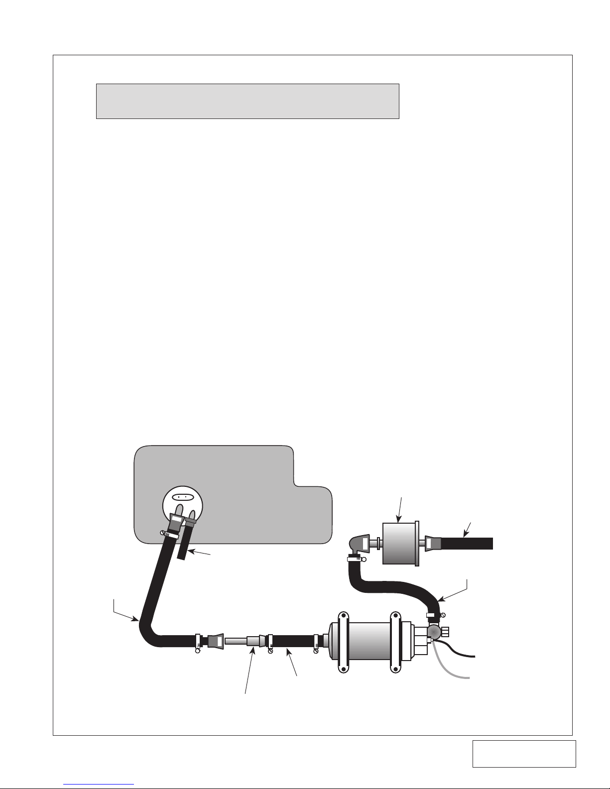
6. T-REX® FUEL PUMP (H.O., S.H.O. and Cobra Systems Only)
ADAPTER FITTING
3/8”x6” FUEL HOSE
RELAY #87
GROUND
5/16”x24” FUEL HOSE
EXISITING FUEL LINE
STOCK FUEL FILTER
RETURN
REPLACE THE
FACTORY FEED
LINE WITH THE
VORTECH
SUPPLIED
PIECE
FUEL
TANK
NOTE: Make sure that the fuel level is below 1/4 tank for
easier installation.
A. Remove spare tire, etc. from trunk.
B. Trim "cut-out" from template and place over spare tire
hold-down. Centerpunch and drill holes 3/16" diameter.
C. Jack up the rear of the car and support with jack
stands.
D. Drop down the fuel tank by loosening the filler neck and the
two tank mounting straps. (There is no need to disconnect
any of the wiring or to completely remove the tank.)
E. Disconnect and remove the original rubber fuel line running
from the tank to the fuel filter. Remove the 90° plastic
fitting from the feed hose and set aside.
F. Attach one end of the supplied fuel line with connections
to the fuel tank pickup (see below). Route the hose around
to the front of the tank in the factory manner.
G. Place the Vortech supplied fuel adapter fitting, located in
the T-Rex pump inlet hose, into the new feed line coming
from the tank. Make sure that the white plastic retainer
clip is in place.
H. Reinstall the fuel tank and filler tube. Take care to route
the fuel lines and vent lines away from exhaust pipes and
provide room so that lines are not crushed between the
floor pan and the tank.
T-REX FUEL PUMP ASSEMBLY
Fig. 6-a
© 2008 Vortech Engineering, Inc.
4
All Rights Reserved, Intl. Copr. Secured
25MAR08 v4.0(86-93 5.0 Mus (4FA v4.0))
P/N: 4FA020-010
Page 18
6. T-REX® FUEL PUMP (H.O., S.H.O. and Cobra Systems Only) cont'd.
I. Mount pump to the underside of the tire well with rubber
mounts, adel clamps and fasteners.
J. Connect the hoses to pump inlet and outlet. This operation
is completed at the Vortech factory for most models.
K. Place the 90° fuel connector (removed from stock line)
into the end of the 5/16" outlet hose from the pump.
L. Connect the 90° end to the inlet side of the fuel filter. Use
cable ties to keep lines up against underbody.
M. Mark and drill a 1/8" hole and mount relay inside trunk in
position as shown in template.
N. From relay terminal #85, tap the yellow wire into the stock
fuel harness in trunk near the right tail light. Tie into red/
purple wire with a scotch lock. (On some model years,
wire may be brownish-green.)
O. Connect the short red wire to the (+) terminal at the fuel
pump relay terminal #87.
P. Connect the longer black wire from the (-) terminal at the
fuel pump to a clean ground.
Q. Connect the short black wire to the ground from relay
terminal #86 (relay screw mount works well).
R. Connect the long red wire from relay terminal #30 to the
fuse box with supplied fuse tap and inline fuse. (The fused
side of the cigarette lighter is the preferred location.)
S. Check over the job and make sure everything is secure and
away from all moving parts and exhaust pipes. Make sure
no wires will rub on sharp edges. After you have activated
the pump, check for any leaks and correct if necessary.
P/N: 4FA020-010
© 2008 Vortech Engineering, LLC
All Rights Reserved, Intl. Copr. Secured
25MAR08 v4.0(86-93 5.0 Mus (4FA v4.0))
5
Page 19
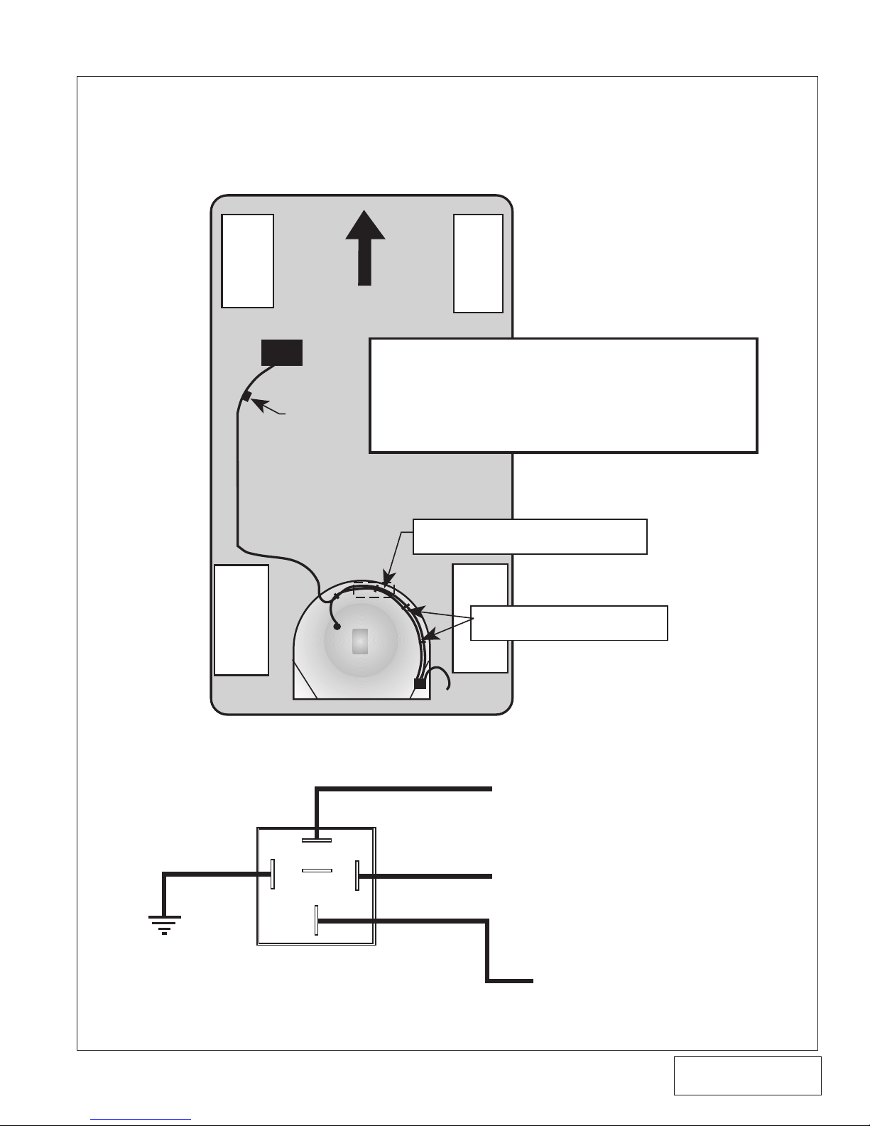
87
87a
30
85
86
FUSE BOX
SPARE TIRE WELL
ROUTE RED POWER LEAD FROM FUSE BOX UNDER CARPET ON
DRIVER SIDE WITH STOCK WIRE HARNESS. TAKE CARE TOAVOID
SHARP EDGES AND NOT TO DAMAGE WIRE INSULATION.
MOUNT RELAYIN RIGHT REAR CORNER OF SPARE TIRE WELL.
MAKE SURE WIRES ARE CONNECTED AS PER RELAY SCHEMATIC
PROVIDEAGOOD GROUND CONNECTION FOR BOTH THE PUMP
AND RELAY THATIS FREE OF RUST OR PAINT.
(+) T-REXª FUEL PUMP
GROUND
FUSE BOX AT CIGAR LIGHTER TAP
(FUSED SIDE)
RED/PURPLE WIRE IN STOCK HARNESS
(Check with test light. When key is turned to “ON”
position, test light should illuminate for 2-3 seconds
& then should turn “OFF” automatically
.)
RELAY WIRING SCHEMATIC
SECURE WIRES WITH ADHESIVE
ANCHORS AND TIE WRAPS
20A INLINE
FUSE
PUMP IS MOUNTED BELOW TIRE WELL
(UNDER CAR)
SCHEMATIC (H.O., S.H.O. and Cobra systems only)
VORTECH T-REX WIRING AND PLACEMENT GUIDE
Fig. 6-a
Fig. 6-b
6
© 2008 Vortech Engineering, Inc.
All Rights Reserved, Intl. Copr. Secured
25MAR08 v4.0(86-93 5.0 Mus (4FA v4.0))
P/N: 4FA020-010
Page 20
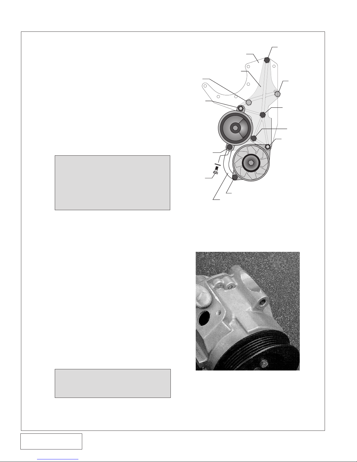
7. MAIN BRACKET ASSEMBLY
3/8-16x1"
MOUNTING PLATE
3/8-16X1-3/4"
7/16-14x1-3/4"
3/8-16x6-1/2"
3/8-16x7"
3/8-16x6-1/4"
install from rear
ALTERNATOR
ALTERNATOR STAY
3/8-16x1"
3/8-16x3/4"
3/8-16x2"
3/8-16x61/4"
install from rear
place .920" spacer
SMOG PUMP
& PULLEY
3/8-16x61/4”
and place .920 spacer
between plate and pump
install from rear
(6-3/4” *)
(7-1/4” *)
MOUNTING BRACKET
Assemble the main bracket, plate and
other parts necessary to relocate the alternator and smog pump and make room
for the supercharger. For 1992 and later
vehicles, please review points A through H
before starting.
A. Measure the length of the pivot boss on
the alternator and record. It should be
very close to 3".
B. In a similar manner, measure the boss on
the smog pump. When combined with the
.920" spacer, it should be 4.050". Record
these measurements so that in the event
of a belt alignment problem, Vortech can
properly advise you.
1986-93 S.H.O./RENEGADE
V-7 KITS ONLY
NOTE: The upper mounting bolt
boss on the smog pump (if
equipped) requires grinding
to allow for fitment of the V-7
compressor (see Fig. 7-b).
C. Place the smog pump and alternator on
the large aluminum mounting bracket as
shown. After making sure the 6 1/4" bolts
have a washer on them, enter the cast
mounting bracket from the rear (coming
towards you). Place the .920" tube spacer
over the bolt on the smog pump. Lower
supercharger mounting plate over bolts.
The idea is to sandwich the alternator
and smog pump between the mounting
bracket and plate. Place washers and
nuts on the 6-1/4" bolts and finger tighten.
For vehicles equipped with alternators
having larger 7/16" pivot bolts, it will be
necessary to enlarge the corresponding
hole in the plate.
D. Start the 3/8-16 x 1" fastener with a
washer at the top of the bracket and
finger tighten. Insert the 6-1/2" and 7"
bolts. These bolts will later hold assembly
to engine.
NOTE: Remember to place the .920"
spacer between the smog
pump and mounting plate.
Fig. 7-a
* V-7 application with aluminum
mounting plate requires 6-3/4" and
7-1/4" bolts.
S.H.O./RENEGADE V-7
KIT ONLY
Fig. 7-b
P/N: 4FA020-010
© 2008 Vortech Engineering, LLC
All Rights Reserved, Intl. Copr. Secured
25MAR08 v4.0(86-93 5.0 Mus (4FA v4.0))
7
Page 21
7. MAIN BRACKET ASSEMBLY (cont'd.)
SMOG PUMP
DIVERTER VALVE ALVEAIR CONTROL V
SHORTEN THIS HOSE 1-1/2”
E. Attach the Vortech alternator brace
between the boss on the smog pump
and alternator with the 3/8-16 x 1" bolts.
On 1992 and later Mustangs, it may be
necessary to drill and tap the "blanked"
hole in the smog pump. To accomplish
this use an R size bit and a 3/8-16 size
tap.
F. Tighten all fasteners in the bracket/
accessory assembly.
G. Lower the entire assembly into position
and start all four fasteners that hold it
to the engine. Tighten all fasteners in a
progressive manner.
H. Reconnect alternator wires and use a tie
wrap to secure the wires.
8. SMOG PUMP HOSES
1986-93 RENEGADE
5.0L KIT ONLY
NOTE: Due to the location of the
Vortech Mondo bypass valve,
removal of the air injection hose
assemblies is required for proper
bypass valve installation. This
modification is for off-road use
only. Disregard the following steps
A thru E.
A. Separate the short hose and bent hose from
the air control valve and place the shorter hose
on the diverter valve (the valve closest to the
firewall) as shown.
B. Connect the air control valve to the short
hose.
C. Trim approximately 1-1/2", or as necessary, off
the longer straight portion of the bent hose for
proper fit.
D. Secure the hose as shown with the stock
clamps.
E. It may be necessary to reroute the vacuum
control line after the supercharger is in place.
Fig. 8-a
© 2008 Vortech Engineering, Inc.
8
All Rights Reserved, Intl. Copr. Secured
25MAR08 v4.0(86-93 5.0 Mus (4FA v4.0))
P/N: 4FA020-010
Page 22
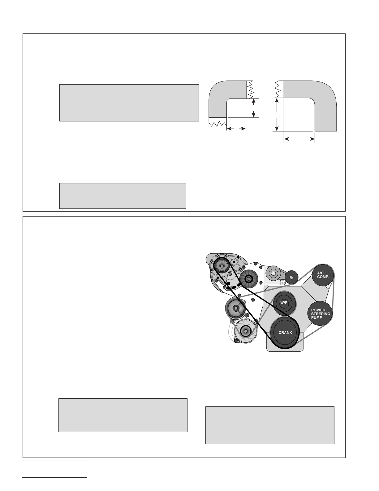
9. RADIATOR HOSE
2"
2"
3"
3"
A. From the stock radiator hose, make two 90° elbows by trimming as
shown. The first is with 3" long legs for the thermostat housing end.
The second, with 2" long legs, is from the middle of the stock hose
and attaches to the radiator.
NOTE: S.H.O. V-7 APPLICATIONS - The
10-rib supercharger pulley supplied
in this kit fits close to the upper
radiator hose. More trimming than
shown in Fig. 9-a may be required.
B. Place the stainless water pipe between the
two hoses placing the shorter leg nearer the
radiator.
C. Position the hoses and tube so there is ample
overlap for sealing and secure with provided clamps.
D. Refill radiator and coolant bottle.
NOTE: Make sure the cooling system
is completely full. Air is often
trapped in 5.0 systems.
Fig. 9-a
10. ACCESSORY BELT TENSIONER MOUNTING BRACKET
A. Secure the factory spring tensioner
assembly to the Vortech belt tensioner
mounting bracket using the 1/2" carriage
bolt.
B. Replace the locking type nut on the A/C
mounting bracket stud closest to the water
pump with a standard nut.
C. Depending on Ford's manufacturing
tolerances, it may be necessary to trim
about 1/8" off the edge of the flange on the
A/C mounting bracket to provide room for
the tensioner mounting bracket.
D. Install the tensioner mounting bracket
with tensioner between the supercharger
mounting plate and A/C bracket stud using
two standard flat washers as a spacer.
Secure with two 3/8-16 x 1" bolts and
washers and a 3/8-16 nut.
E. Reinstall radiator shroud and fan assembly.
(Slight shroud trimming may be required
on S.H.O. applications.)
Fig. 10-a
NOTE: On S.H.O. applications, a fan
spacer, studs and nuts have
been supplied. Install these
items before installing the fan
F. Reinstall stock accessory belt. (On S.H.O.
applications, use the supplied 888 belt for
the accessory drive.)
P/N: 4FA020-010
© 2008 Vortech Engineering, LLC
All Rights Reserved, Intl. Copr. Secured
25MAR08 v4.0(86-93 5.0 Mus (4FA v4.0))
NOTE: Check the accessory belt
tensioner pulley alignment. It
may be necessary to add or
remove a washer to the stud
behind the tensioner bracket.
9
Page 23
11. SUPERCHARGER MOUNTING
*A. Place the oil drain hose onto the supercharger drain fitting and
secure with a hose clamp. Arrange the clamp screw housing so
it will not interfere with the mounting plate when installed.
*B. Feed the oil drain hose over the top of the smog pump and down
towards the oil pan fitting while lowering the supercharger into
position.
C. Secure the supercharger with five 3/8-16 x 1" bolts and AN
washers.
*D. Connect the lower end of the oil drain hose to the fitting on the
pan and secure with a hose clamp.
**E. Secure the remote drain hose away from the belt and other hoses
using tie-wraps.
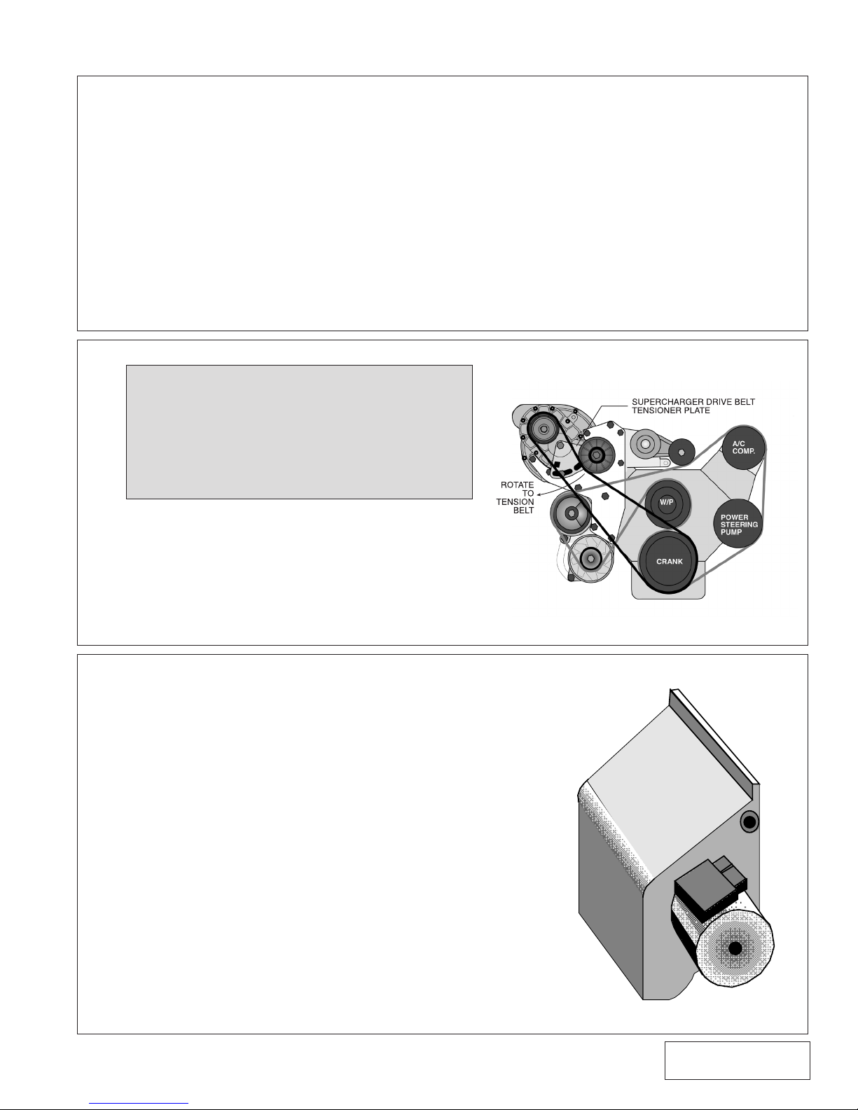
12. SUPERCHARGER DRIVE BELT
1986-93 RENEGADE 5.0L KIT ONLY
NOTE: The factory water pump pulley must be
removed and replaced with an aftermarket unit for proper supercharger drive belt
clearance. Also, an aftermarket electric
fan is recommended, although the factory
mechanical fan may still be retained with
minor clearance modifications.
* Engine oil fed kits only
** V3 kits only
A. Place the supercharger belt idler assembly on
the supercharger using the 12mm bolts and
washers. Position the thin head bolt nearest
pulley.
B. Fit the supercharger drive belt over the new
crank pulley and supercharger pulley.
C. Tension the belt by rotating the tensioner plate
and secure.
Fig. 12-a
13. AIR FILTER ASSEMBLY (skip to step I for Renegade applications
and step J for S.H.O. applications)
A. Place the Vortech air filter cover against the inner fender
just behind the right headlight. Use it as a template to
mark and drill two 3/32" holes. Do not install the cover
at this time.
B. Insert the mass air flow (MAF) sensor into the back of the
air filter cover. Place the air filter with clamp, from the
inside, over the protruding MAF and the air filter flange.
Rotate the MAF so that the connector runs parallel to
the top as shown. Tighten the clamp.
C. Mount the air filter assembly behind the headlight and
secure with sheet metal screws provided.
D. Attach the 3” molded elbow to the supercharger with the
sleeve and clamps.
E. Connect the 3” flex tube to the molded elbow and the
back of the MAF with the 3" x 1" adapter sleeve on the
MAF (as a spacer) and secure with clamps.
F. Connect the air discharge tube to the throttle body and
supercharger with the sleeves and clamps provided.
Fig. 13-a
10
© 2008 Vortech Engineering, Inc.
All Rights Reserved, Intl. Copr. Secured
25MAR08 v4.0(86-93 5.0 Mus (4FA v4.0))
P/N: 4FA020-010
Page 24
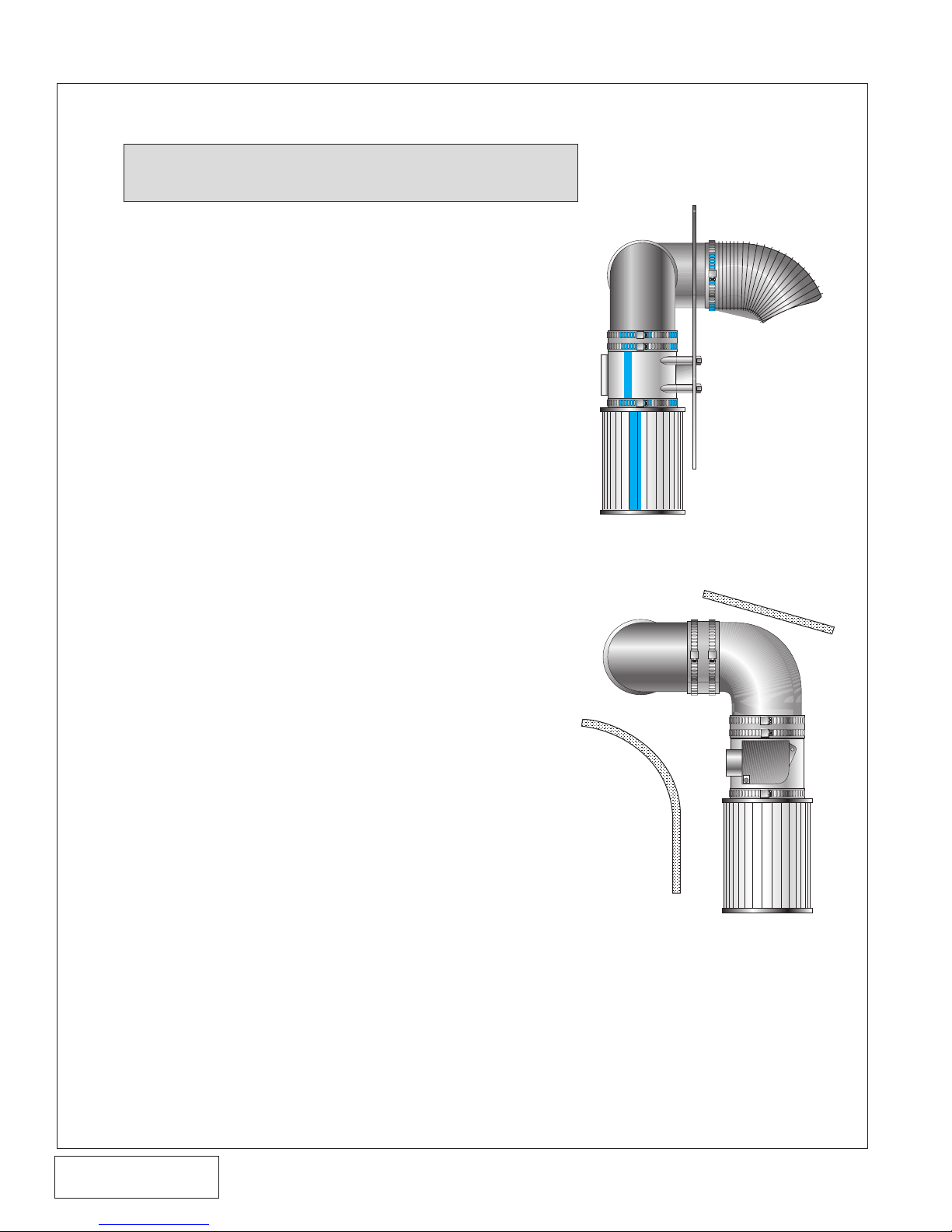
13. AIR FILTER ASSEMBLY (skip to step I for Renegade applications)
cont'd.
NOTE: If kit is a High Output or Cobra model refer to
step 16, and Step J for S.H.O. applications.
G. Clamp the provided rubber cap onto the vent fitting
on the throttle body.
H. With the 3/8” rubber hose, route blowby to the air filter
cover through the inline filter provided.
I. 1986-93 RENEGADE 5.0L KIT ONLY:
Install the supplied 4” aluminum elbow onto the
supercharger inlet using the silicone sleeve and #64
clamps. The inlet elbow is supplied with cast-in bosses
that can be drilled and threaded for a valve cover
breather fitting (Note: The engine valve cover vent
MUST be properly baffled or else the supercharger
may pull in oil from the engine). The aluminum elbow
can then be attached to the vehicles’ MAF and air
inlet filter. Vehicles equipped with an Anderson Power
Pipe can be easily adapted to the Vortech inlet elbow
by using the supplied 4” silicone sleeve and #64
clamps.
J.
S.H.O. V-7 KITS ONLY: INNER FENDER AIR INLET KIT
1. Thread the supplied 3/8 x 90" x 1/4 NPT fitting
into the 4" aluminum inlet elbow.
2. Install the elbow onto the supercharger inlet using
the supplied silicone sleeve and #64 clamps.
3. Route the supplied 3/8" blowby hose from the
valve cover to the supercharger inlet elbow fitting
and trim if necessary. (Note: The engine valve
cover vent MUST be properly baffled or else the
supercharger may pull in oil from the engine).
4. Cut out the Vortech provided template. Using the
template, mark and drill the hole patterm into the
fender apron.
5. Remove the round plastic cover at the rear of the
oval opening on the inner fender.
6. Remove the plastic fender lining from the right
fender.
7. Attach the filter to the mass air flow (MAF) sensor
and secure with the clamp. Place the MAF in the
fender from the outside and secure with fasteners
provided from the engine compartment side.
8. Attach the short sleeve to the MAF and slip one
of the elbows inside the sleeve facing rearward
(see diagram).
9. Connect the 3" long sleeve to the rearward facing
elbow. Slip the second elbow through the round
hole to the engine compartment and secure into
the 3" sleeve.
Fig. 13-b
Front View
Fig. 13-c
Right Side View
P/N: 4FA020-010
© 2008 Vortech Engineering, LLC
All Rights Reserved, Intl. Copr. Secured
25MAR08 v4.0(86-93 5.0 Mus (4FA v4.0))
11
Page 25
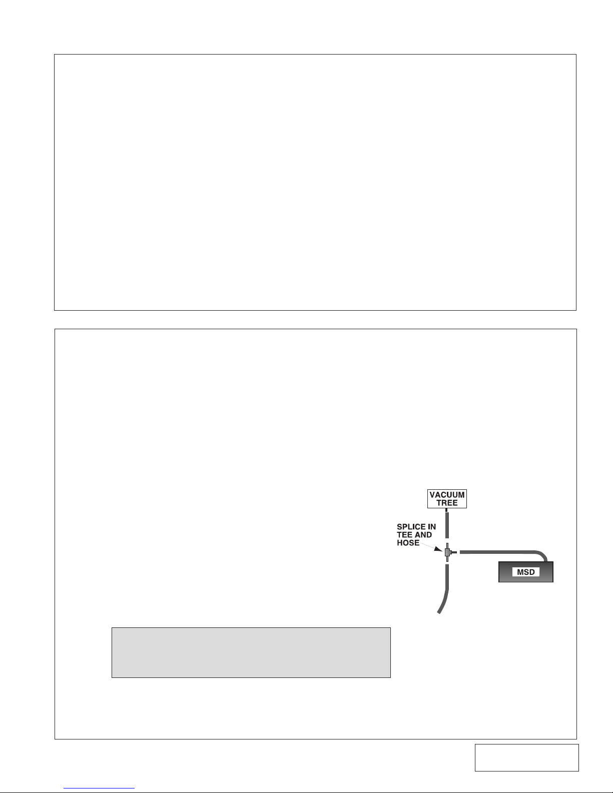
13. AIR FILTER ASSEMBLY, cont'd.
10. In the engine compartment, connect the flex hose from
the elbow extending through the hole to the elbow on
the supercharger.
11. Cut the MAF wires 3" to 4" away from the MAF
connector.
12. Slip 1" long sections of the supplied shrink tubing over
each wire before soldering.
13. Using the supplied wiring, solder wire extensions
for the MAF and connector through the fender well.
Position shrink tube over the solder joint and gently
heat until the tube seals the joint.
14. Replace the inner fender lining.
14. IGNITION/BOOST CONTROL INSTALLATION
(High Output and Cobra systems only)
A. The Ignition/Boost Control unit has been prewired for
installation convenience. Installation is a simple matter
of disconnecting the stock connector at the ignition coil
and plugging in the new adapter. Then plug the stock
connector into the adapter.
B. The next step is to provide a good ground for the black
wire and mounting the box in as cool a place as possible
under the hood. The box should be mounted with the
aluminum cover on the bottom.
C. Using the supplied 5/32" hose and 5/32" tee, connect
the vent on the control unit to the FMU vacuum/pressure
hose
(see graphic at right).
D. Route the Ignition/Boost Control wires through the
firewall from the interior side. Mount the knob in an easily
accessible place.
E. Connect the wires to the plastic oval wiring connector
on the Ignition/Boost Control unit using the snap-on
connector supplied in the Ignition/Boost Control kit.
NOTE: The wiring to the boost/control knob can be
matched to either of the corresponding wires
in the boost retard connector.
12
Fig. 14-a
© 2008 Vortech Engineering, Inc.
All Rights Reserved, Intl. Copr. Secured
25MAR08 v4.0(86-93 5.0 Mus (4FA v4.0))
P/N: 4FA020-010
Page 26
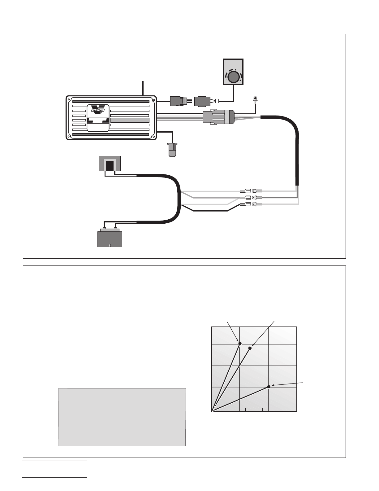
14. IGNITION/BOOST CONTROL INSTALLATION
BOOST
RETARD
0
1
2
3
SUPERCHARGERS
Ignition/Boost
Control
MANUFACTUREDFOR
VORTECHSUPERCHARGERS
BY
MSD
¨
BLACK
WHITE
RED
ORANGE
BLACK
WHITE
RED
ORANGE
IGNITION
COIL
FROM FACTORY COIL HARNESS
MAGNETIC PICKUP
CONNECTOR (NOT USED)
BOOST
RETARD
CONNECTOR
GROUND
TO MANIFOLD
VACUUM
15
10
5
5 psi at 3° per lb. 7 psi at 2° per lb.
10 psi at
1/2° per lb.
MAX.
RETARD=15°
DEGREES OF RET ARD
5
7
10
PSI BOOST
(High Output and Cobra systems only) cont'd.
15. IGNITION/BOOST CONTROL UNIT OPERATION (High Output and
Cobra Systems only)
A. The Ignition/Boost Control unit is designed
to retard ignition in relation to boost.
B. The unit is adjustable from 0° of ignition
retard to 3° of ignition retard for each pound
of boost, up to a maximum of 15°.
C. Using the 1° per pound position as a starting
P/N: 4FA020-010
© 2008 Vortech Engineering, LLC
All Rights Reserved, Intl. Copr. Secured
25MAR08 v4.0(86-93 5.0 Mus (4FA v4.0))
place, adjust the ignition retard knob until
just beyond the point of detonation. Use
third gear for testing in a safe area or road.
Adjust the retard according to changes in
altitude and fuel quality.
CAUTION: It is extremely important
that the boost retard never
be turned to 0°. It is recommended that in stock street
applications, the knob be
positioned at 1° per lb. to
start.
Fig. 14-b
13
Example of Ignition Retard vs. Boost:
Fig. 15-a
Page 27
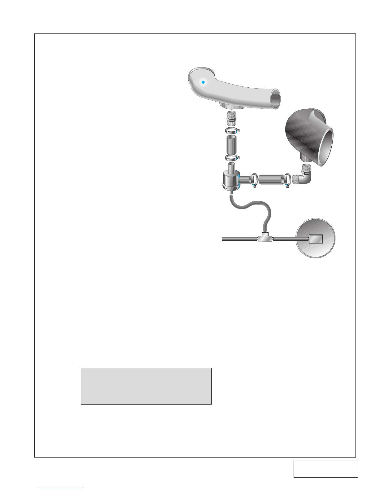
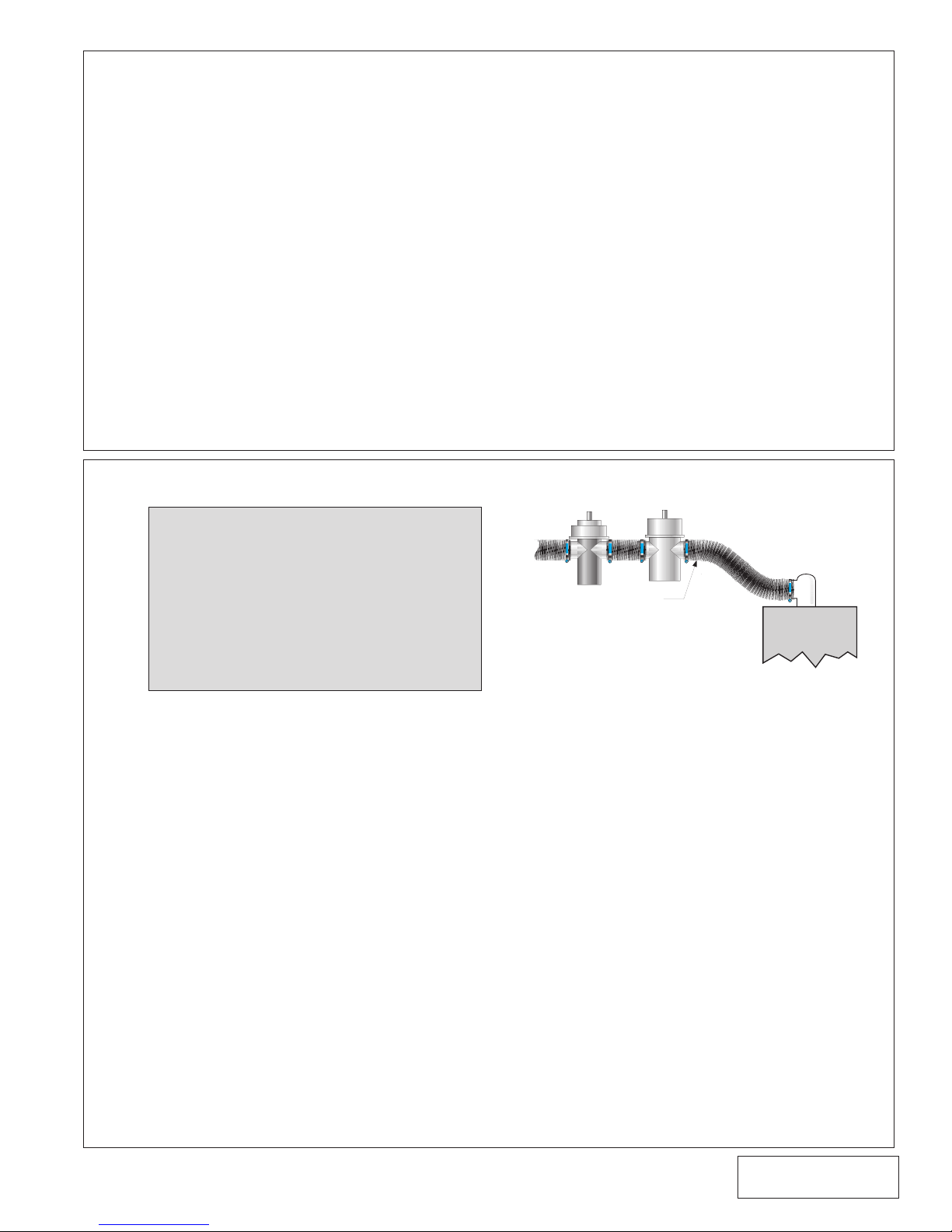
16. VORTECH BYPASS VALVE (H.O. and Cobra Systems Only. Skip to
step H. for S.H.O. V-7 and Renegade applications)
A. Install the 90° inlet tube onto the
supercharger with the fitting pointing
down.
B. Place the hoses as shown on the
valve and secure it with the clamps
provided.
C. Attach one end of the small vacuum
line onto the valve.
D. Install the valve and hoses onto the
inlet elbow fitting and secure with the
clamps.
E. Install the aluminum discharge tube
(between the throttle body and
supercharger) while guiding the hose
onto the valve. Secure hoses with the
clamps.
F. Route the supplied 5/32" vacuum line
and TEE so that you can splice into
the FMU vacuum/pressure line.
G. Make sure everything is secure and
that no fuel lines or wires have been
accidentally moved into harm's
way.
H. 1986-93 S.H.O. V-7 AND
RENEGADE 5.0L KIT ONLY:
BYPASS
VALVE
DISCHARGE
TUBE
Fig. 16-a
FMU
INLET
ELBOW
1. Mount the supplied bypass valve to the
aluminum discharge tube using the gasket
and hardware.
2. Connect the supplied 1-3/4" or 2" diameter
silicone sleeve to the outlet of the bypass
valve.
3. Mount the aluminum discharge tube and
valve assembly to the vehicle using the
supplied silicone sleeves and clamps.
4. Align the bypass outlet sleeve to the inlet
elbow boss located on the supercharger
inlet elbow.
NOTE: MAF equipped applicaions
require the bypass discharge
air to be routed back into the air
inlet so that proper air sampling
can take place.
5. Align the discharge tube properly and
tighten all clamps.
6. Route the supplied 1/4" vacuum line and
TEE so that it is spliced into the FMU/
vacuum line.
14
© 2008 Vortech Engineering, Inc.
All Rights Reserved, Intl. Copr. Secured
25MAR08 v4.0(86-93 5.0 Mus (4FA v4.0))
P/N: 4FA020-010
Page 28
WARNING: Do not attempt to operate the vehicle
until ALL components are installed and
ALL operations are completed including
the final check.
17. FINAL CHECK
A. Reconnect the battery.
B. If your vehicle has gone over 10,000
miles since its last spark plug change,
you will need to change the spark plugs
now before test driving the vehicle.
C. Check all fittings, nuts, bolts and clamps
for tightness. Pay particular attention to
oil and fuel lines around moving parts,
sharp edges and exhaust system parts.
Make sure all wires and lines are properly
secured with clamps or tie wraps.
D. Check all fluid levels, making sure that
your tank is filled with 91 octane or higher
fuel before commencing test drive.
E. Visually inspect the fan, belts and
shroud for clearance before running
the vehicle. Pay special attention to the
upper radiator hose-to-belt and pulley
clearance.
F. Start engine and allow to idle a few
minutes, then shut off.
G. Recheck to be sure that no hoses, wires,
etc. are near exhaust headers or moving
parts and for signs of any fluid leakage.
Check ignition timing to make sure it
is set to stock specifications before
commencing test drive.
H. PL EASE TAKE SPECIAL NOTE :
Operating the vehicle without ALL the
subassemblies completely and properly
installed may cause FAILURE OF MAJOR
COMPONENTS.
I. Test drive the vehicle.
J. The supercharger drive belt stretches
initially and will require adjustment
between 250 and 400 miles.
K. Read the STREET SUPERCHARGER
SYSTEM OWNER'S MANUAL (RACE
OW NE R 'S M AN U AL F OR THE
RENEGADE KIT) AND RETURN THE
WARRANTY REGISTRATION FORM
within thirty (30) days of purchasing
your supercharger system to qualify
(Renegade systems are designed for
racing and come with a standard 6 month
warranty).
For internally lubricated V3 units only
This supercharger has been factory pre-filled with
special Vortech synthetic lubricant. Oil does not
need to be added to a brand new unit; however a
fluid level check should be performed.
Prior to operating the supercharger on the vehicle
and after installation onto the vehicle:
Remove the factory installed flat-head brass
shipping plug (not the dipstick) from the top of the
supercharger case. Replace the sealed shipping
plug with the supplied “vented” plug. Do not
operate the supercharger without it. Check the
supercharger fluid level.
Fluid level checking procedure:
1. Ensure that the .06” copper sealing washer
is located on the dipstick base.
2. Thread the clean dipstick into the unit until
it seats.
3. Once the dipstick has seated, remove the
dipstick from the unit. Fluid should register
in the crosshatched area on the dipstick.
4. DO NOT OVERFILL!!! Drain excess fluid from
the unit if it is above the maximum level on
the dipstick.
Check the fluid level using the dipstick at least
every 2,500 miles.
Initial supercharger fluid change must be performed
at 2,500 miles. The supercharger fluid must be
changed at least every 7,500 miles.
Drain the fluid, refill the unit with 4 oz. of Vortech
V3 lubricating fluid and then confirm proper oil level
using the dipstick. DO NOT OVERFILL!!!
WARNING: Use of any other fluid other than
the special Vortech lubricant will
void the warranty and may cause
component failure.
P/N: 4FA020-010
© 2008 Vortech Engineering, LLC
All Rights Reserved, Intl. Copr. Secured
25MAR08 v4.0(86-93 5.0 Mus (4FA v4.0))
15
Page 29
ENGINEERING, LLC
®
1650 PACIFIC AVENUE • CHANNEL ISLANDS, CA 93033-9901 • (805) 247-0226
FAX (805) 247-0669 • www.vortechsuperchargers.com • M-F 8:00 AM - 4:30 PM PST
© 2008 Vortech Engineering, Inc.
All Rights Reserved, Intl. Copr. Secured
25MAR08 v4.0(86-93 5.0 Mus (4FA v4.0))
P/N: 4FA020-010
 Loading...