

Ford Cougar 1967, Fairlane 1967, Falcon 1967, Mercury Intermediate 1967, Mustang 1967 Shop Manual
Page 1
Page 2
Copyright © 2006, Forel Publishing Company, LLC, Woodbridge, Virginia
All Rights Reserved. No part of this book may be used or reproduced in any manner
whatsoever without written permission of Forel Publishing Company, LLC. For
information write to Forel Publishing Company, LLC, 3999 Peregrine Ridge Ct.,
Woodbridge, VA 22192
1967 Cougar, Fairlane, Falcon, Mercury and Mustang Shop Manual
(Form 7760-67, First printing – March 1967)
ISBN: 0-9673211-4-X
EAN: 978-0-9673211-4-1
Forel Publishing Company, LLC
3999 Peregrine Ridge Ct.
Woodbridge, VA 22192
Email address: [email protected]
Website: http://www.ForelPublishing.com
This publication contains material that is reproduced and distributed under a
license from Ford Motor Company. No further reproduction or distribution of the
Ford Motor Company material is allowed without the express written permission
of Ford Motor Company.
Disclaimer
Although every effort was made to ensure the accuracy of this book, no representations or warranties of
any kind are made concerning the accuracy, completeness or suitability of the information, either expressed
or implied. As a result, the information contained within this book should be used as general information
only. The author and Forel Publishing Company, LLC shall have neither liability n or responsibility to any
person or entity with respect to any loss or damage caused, or alleged to be caused, directly or indirectly by
the information contained in this book. Further, the publisher and author are not engaged in rendering legal
or other professional services. If legal, mechanical, electrical, or other expert assistance is required, the
services of a competent professional should be sought.
Page 3
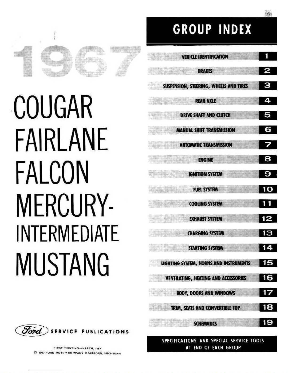
GROUP INDEX
NW-
.
FALCON
VEHICLE IDEMIIRCATION
BRAKES
SUMMON, STEERING, INNERS AND TIRES
REAR AXLE
DRIVE SHAFT AND CLUTCH
MANUAL SHIFT TRANSMISSION
AUTOMATIC TRANSMISSION
ENGINE
:
.
1GNRION SYSTEM
FUEL SYSTEM
10
1
2
3
4
5
6
7
9
COOLING SYSTEM
MERCURY-
EXHAUST SYSTEM
imam
Mir '
SMOG
VARTIHG SYSTEM
SYSTEM,
MUSTANG
SERVICE PUBLICATIONS
IPSTPF FIT NG-0ARCH_ 1907
19
19+7 FORD 1111OYpM CO PAPAW, DEAR yQR11
. 1NIC
MPIMI
nt
SPECIFICATIONS AND SPECIAL SERVICE TOOLS
.H14AN
.ATING, HEATING AND ACCESSORIES
.
BODY, DOORS AND WINDCNV5
TM % SEATS AND CONVERTIBLE TOP
5O
AT END OF EACH GROUP
HORNS
$
A
SYSTEM
AND INSTRUMENTS
5
11
12
13
14
15
16
1$
19
Page 4
FOREWORD
This shop manual provides the Service Technician with information
for the proper servicing of the
1967
Cougar, Fairlane, Falcon,
Mercury Intermediate, Comet and Mustang cars.
The maintenance schedule and procedures for maintenance oper-
ations are published in the
1967
hsenger Car Maintenance and
Lubrication Manual.
The information in this manua! is grouped according to the type
of work being performed, such as diagnosis and testing, frequently performed adjustments and repairs, in-vehicle adjustments, overhau!, etc. Specifications and recommended special tools areincluded.
Refer to the opposite page for important vehicle identification
data.
The descriptions and specifications in this manual were in effect at
the time this manual was
approved for printing. The Ford Motor
Company reserves the right to discontinue models at any time, or
change specifications or design, without notice and without incurring obligation.
Page 5
Page 6
1
-2
GROUP
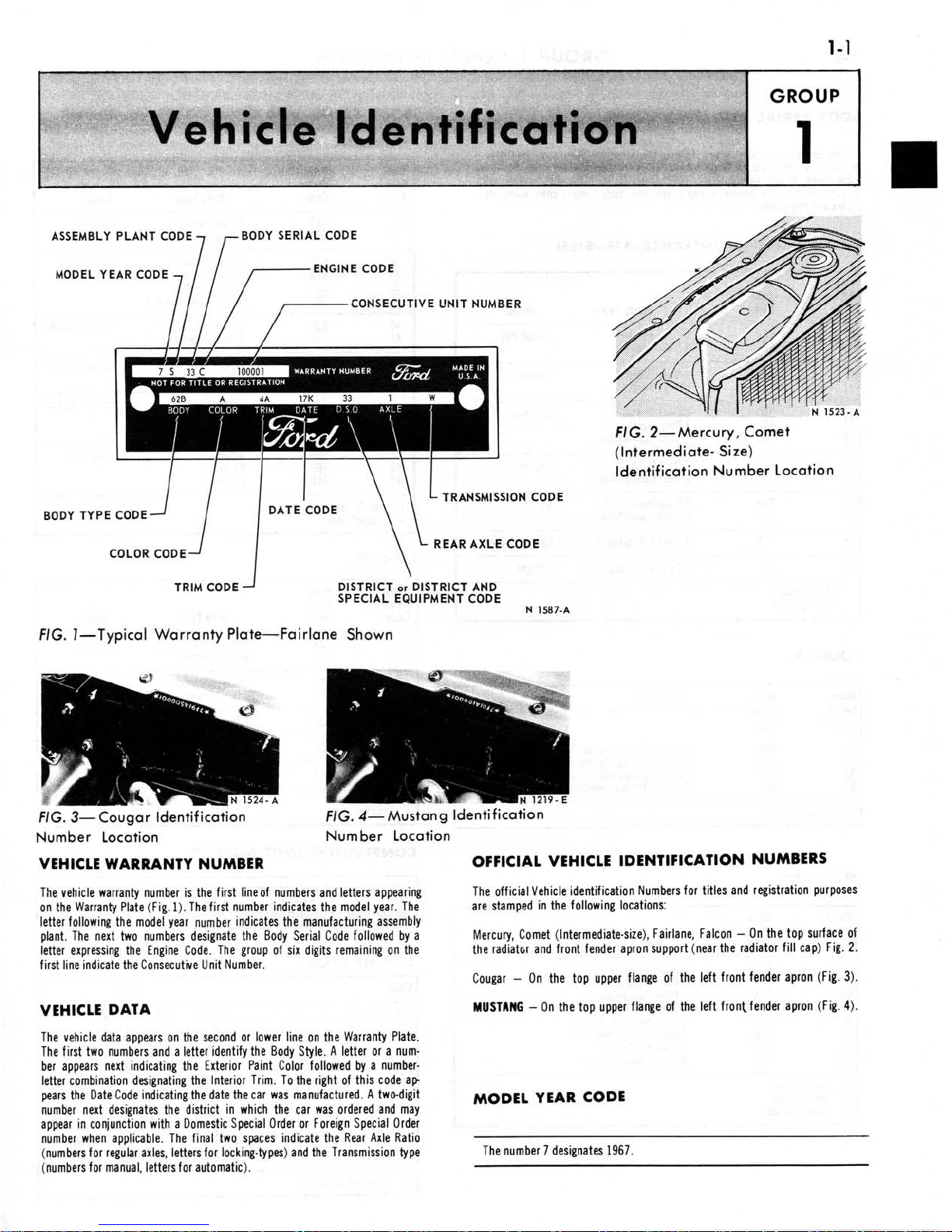
1-Vehicle Identification
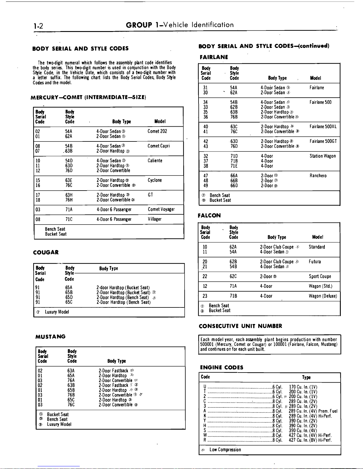
BODY SERIAL AND STYLE CODES
BODY SERIAL AND STYLE
CODES-4continu.d)
FAIRLANE
The two-digit numeral which follows the assembly plant, code identifies
the body series. This two-di it number is used in
coniunct~on with the Body
Style Code, in the Vehicle bate, which consists of a
two-d~git number with
a letter suffix. The following chart lists the Body Serial Codes, Body Style
Codes and the model.
MERCURY4OMET (INTERMEDIATE-SIZE)
w
Serial
Body
Code
Sbk
Code Body TY pe Model
02 54A 4-Door Sedan
3
Comet 202
01 62A
2.Door Sedan
61
08 54 B &Door Sedan Comet Capri
07
:63B 2-Door Hardtop
8
10 540 4-Door Sedan
3
Caliente
11
630 2-Door Hardtop
O
12 76 D 2-Door Convertible
15 63E 2-Door Hardtop
@
Cyclone
16 76C
2.Door Convertible
@
17 63H 2-Door Hardtop
3
G T
18 76H 2-Door Convertible
@)
03 7 1A 4-Door 6 Passenger Comet Voyager
08 71C 4-Door 6 Passenger Villager
Bench Seat
Bucket Seat
COUGAR
-.
MY
Body Body TY pe
Serial Style
Code Code
91 65A 2-door Hardtop (Bucket Seat)
9 1
658 2-Door Hardtop (Bucket Seat)
8
91 65D 2-Door Hardtop (Bench Seat)
2;
9 1 65C 2-Door Hardtop (Bench Seat)
@
Luxury Model
B+Y B*
Serlal
-
Style
Code Code Body Type
.
Model
3 1 54A
4.Door Sedan
@
Fairlane
30 62A 2-Door Sedan
s
34 548 &Door Sedan
2)
Fair lane 500
33
628 2-Door Sedan
8
35 638 2-Door Hardtops
36 76 B 2-Door Convertible
a
40 63C 2-Door Hardtop
~s
Fairlane 500XL
41 76C 2-Door Convertible
2
42 63D 2-Door Hardtop Fairlane 500GT
43 76D 2-Door Convertible
3
32 71D &Door Station Wagon
37 718 4-Door
38 71E
&Door
47 66A 2-Door
@
Ranchero
48
668 2.Door
3
49 66 D 2-Door
m
@
Bench Seat
@
Bucket Seat
FALCON
Body
.
!$
Serial
Code Code Body Type Model
10 62A 2-Door Club Coupe
.!I
Standard
11 54A Sedan
3
20 628 2-Door Club Coupe s Futura
2
1 548 4-Door Sedan
22 62C 2-Door
@
Sport Coupe
12 71A &Door Wagon (Std.)
23 718 &Do01 Wagon (Deluxe)
o
Bench Seat
o
Bucket Seat
CONSECUTIVE UNIT NUMBER
MUSTANG
Be
Serial
Body
Sgle
Code Code Body TY pe
02 63A 2-Door Fastback
Q'
01 65A 2-Door Hardtop
Ci'
03 76A 2-Door Convertible
g!
02 638 2-Door Fastback
-'I
:z
01 658 2.Door Hardtop
.fi
:3)
03 768 2-Door Convertible
:D
@
0
1 65C 2-Door Hardtop
B)
03 76C 2.Door Convertible
(8
Bucket Seat
@
Bench Seat
o
Luxury Model
Each model year, each assembly plant begins production with number
500001 (Mercury, Comet or Cougar) or 100001 (Fairlane, Falcon, Mustang)
and continues on for each unit built.
ENGINE CODES
Code TYP
U
...........................................................
6 Cyl.
170 Cu. In.
(lV)
T
.........................................................
6 Cyl.
200
Cu. In. (1V)
2
.........................................................
6 Cyl.
.ti
200 Cu. In. (lV)
..................
C
........................................
:
8 Cyl. 289 Cu. In. (2V)
3
...........................................................
8 Cy I.
1:
289 Cu. In. (2V)
A
..........................
:
..............................
8 Cyl.
289 Cu. In. (4V) Prem. Fuel
K
........................................................
8 Cyl. 289 Cu. In. (4V) Hi-Perf.
Y
...........................................................
8 Cyl.
390 Cu.
In. (2V)
H
...........................................................
8 Cy I. 390 Cu. In. (2V)
S
...........................................................
8 Cyl.
390 Cu.
In. (4V)
W
...........................................................
8 Cyl.
427 Cu.
In. (4V) HLPerf.
R
...........................................................
8 Cyl.
427 Cu. In.
(8V) Hi-Perf.
;!I
Low Compression
Page 7
GROUP
I-Vehicle Identification
Code
TYP
1
.............................................................................................
Speed Manual
2
............................................................................................
Overdrive
3
.............................................................................................
Sped Manual
5
.............................................................................................
Sped Manual
W
...........................................................................................
Automatic (C4)
U
.........................................................................................
Automatic (C6)
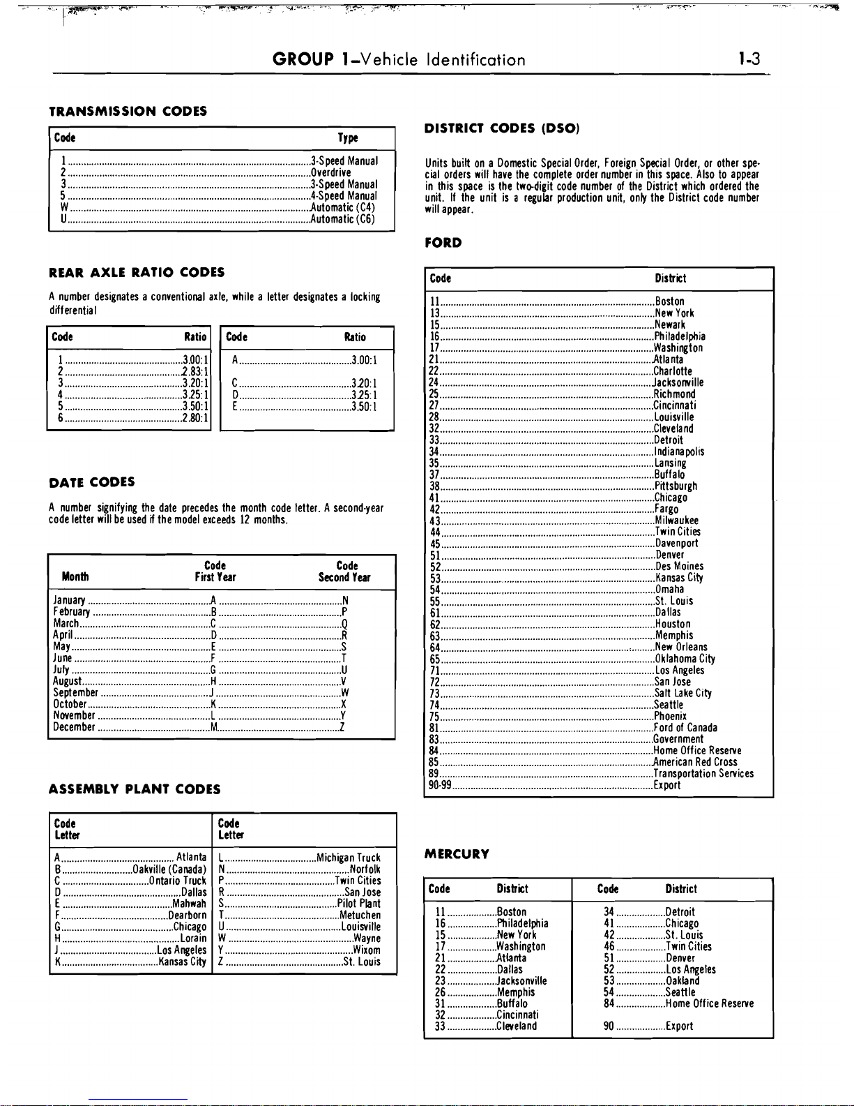
TRANSMISSION CODES
DISTRICT CODES (DSO)
Units built on a Domestic Special Order, Foreign Special Order, or other spe-
cial orders will have the complete order number in this space. Also to appear
in this space is the
twedigit code number of the District which ordered the
unit. If the unit is a regular production unit,
only the District code number
will appear.
FORD
REAR AXLE RATIO CODES
A number designates a conventional axle, while a letter designates a locking
differential
DATE CODES
A
number signifying the date precedes the month code letter. A second.year
code letter will be used
if
the model exceeds 12 months.
Code Code
Month First Year
Second Year
January
...............................................
A
...............................................
N
February
............................................
B
...............................................
P
March
................................................
C
...............................................
Q
April
..............................................
D
...............................................
R
May
.................................................
E
...............................................
S
June
...................................................
F
...............................................
T
July
.....................................................
G
...............................................
U
August
................................................
ti
...............................................
V
September
.........................................
J
................................................
W
...............................................
October K
...............................................
X
November
.........................................
L
...............................................
Y
December
...........................................
M
...............................................
Z
ASSEMBLY PLANT CODES
Code District
11
..................................................................................
Boston
13
..................................................................................
New York
15
..................................................................................
Newark
16
..................................................................................
Philadelphia
17
..................................................................................
Washington
21
.................................................................................
Atlanta
22
..................................................................................
Charlotte
24
.................................................................................
Jacksomille
25
..................................................................................
Richmond
27
..................................................................................
Cincinnati
28
.................................................................................
Louisville
32
..................................................................................
Cleveland
33
.................................................................................
Detroit
34
..................................................................................
Indianapolis
..................................................................................
35 Lansing
37 Buffalo
..................................................................................
..................................................................................
38 Pittsburgh
41
..................................................................................
Chicago
..................................................................................
42 Fargo
43
..................................................................................
Milwaukee
44
.................................................................................
Twin Cities
45
..................................................................................
Davenport
..................................................................................
51 Denver
..................................................................................
52 De Moines
53
..................................................................................
Kansas City
54
................................................................................
Omaha
55
..................................................................................
St Louis
.................................................................................
61 Dallas
.................................................................................
62 Houston
..................................................................................
63 Memphis
64
................................................................................
New Orleans
..................................................................................
65 Oklahoma City
..................................................................................
71 Lo Angeles
..................................................................................
72 an Jose
..................................................................................
73
I
Lake City
74
................................................................................
Seattle
75
..................................................................................
Phoenix
..................................................................................
81 Ford of Canada
..................................................................................
83 Government
.................................................................................
84
Home Office Reserve
.................................................................................
85 American Red Cross
89
..................................................................................
Transportation Services
90-99
.............................................................................
Export
Code
Letta
A
...........................................
Atlanta
B
...........................
Oakville (Canada)
C
.................................
Ontario Truck
D
.........................................
Dallas
E
..........................................
Maw
F
.........................................
earn
G
...........................................
Chicago
H
............................................
Lorn
J
.....................................
Los Angeles
K
.....................................
Kansas City
MERCURY
Code
Letta
L
...................................
Michigan Truck
...............................................
N Norfolk
P
..........................................
Twin Cities
R
.............................................
an Jose
S
...........................................
Po Plant
T
............................................
Metuchen
U
............................................
Louisville
W
................................................
Wayne
Y
.................................................
Wixom
Z
.........................................
St Louis
Code District
11
...................
Boston
16
...................
Philadelphia
...................
15 New York
17
...................
Washington
21
..................
Atbnta
22
...................
Dallas
23
...................
Jacksonville
26
...................
Memphis
31
...................
Buffalo
...................
32 Cincinnati
...................
33 Cleveland
1
Code District
34
...................
Detroit
41
...................
Chicago
42
...................
St. Louis
46
...................
Twin Cities
51
...................
Denver
52
...................
Los Angeles
...................
53 Oakland
54
...................
Seattle
84
...................
Home Office Reserve
...................
90 Export
Page 8
GROUP
1-Vehicle Identification
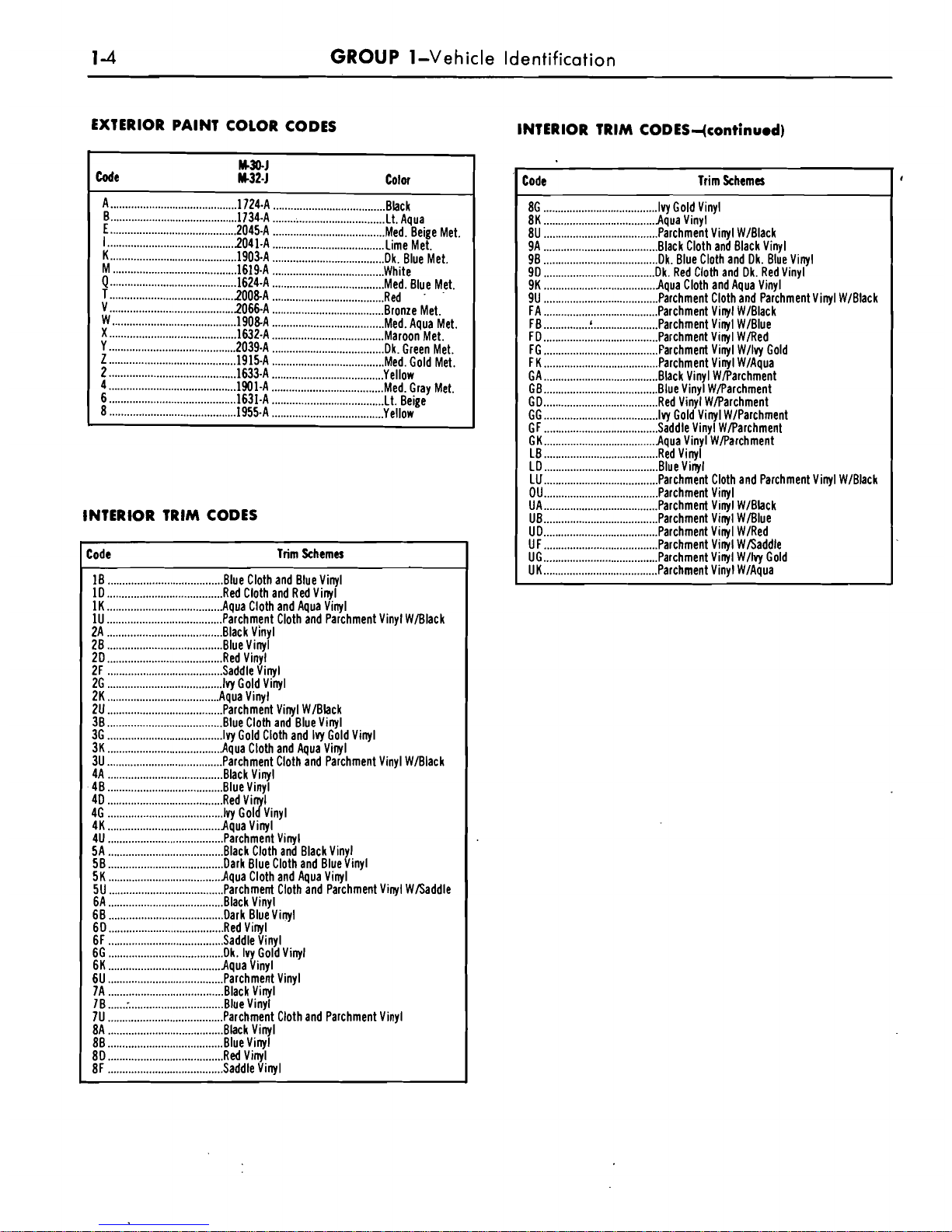
EXTERIOR PAINT COLOR CODES
M30-J
Code
M32-J
Color
...........................................
A 1724-A
......................................
Bbc k
B
...........................................
A
......................................
Lt Aqua
E
...........................................
2045
......................................
Me. Beige Met.
I
...........................................
21
......................................
Lime Met.
K
...........................................
1-A
......................................
Dk. Blue Met.
M
..........................................
1619
......................................
White
Q
...........................................
16244
......................................
Med. Blue Met.
T
..........................................
A
......................................
Red
.
V
..........................................
2066
......................................
Bronze Met.
W
.......................................... A ......................................
Me. Aqua Met.
X
...........................................
1632-
......................................
Maroon Met.
Y
...........................................
203
Dk Green Met.
......................................
Z
...........................................
11-
......................................
Me. Gold Met.
2
...........................................
A
......................................
Yellow
4
...........................................
A
Me. Gray Met.
......................................
6
...........................................
163-A
......................................
Lt Beige
8
...........................................
1955-
......................................
Yellow
INTERIOR
TRIM
CODES
Code Trim Schema
10
.......................................
Be Cloth and Blue Vinyl
1D
.......................................
Red Cloth and Red Vinyl
1K
.......................................
Aqua Cloth and Aqua Vinyl
1U
.......................................
Parchment Cloth and Parchment Vinyl WBlack
2A
.......................................
Black Vinyl
28
.......................................
Be Vinyl
20
.......................................
Red Vinyl
2F
.......................................
Sad Vinyl
2G
.......................................
I
Gold Vinyl
2K
......................................
Aqua Vlnyl
2U
.......................................
Parchment Vinyl WIBbck
38
.......................................
Be Cloth and Blue Vinyl
36
.......................................
I
Gold Cloth and Ivy Gold Vinyl
3K
.......................................
Aqua Cloth and Aqua Vtnyl
3U
.......................................
Parchment Cloth and Parchment Vinyl WBlack
4A
.......................................
Black Vinyl
48
.......................................
Be Vinyl
4D
.......................................
RVi 1
4G
........................................
~oly~in~l
4K
......................................
Aqua Vlnyl
4U
.......................................
Parchment Vinyl
SA
.......................................
Black Cloth and Black Viny!
SB
.......................................
Dark Blue Cloth and BlueVtnyl
SK
......................................
Aqua Cloth and Aqua Vinyl
SU
.......................................
Parchme Cloth and Parchment Vinyl W/Saddle
6A
.......................................
Black Vinyl
60
.......................................
Dark Bluevinyl
60
.......................................
Red Vinyl
6F
.......................................
Sad Vinyl
6G
.......................................
Dk Ivy Gold Vinyl
6K
......................................
Aqua Vinyl
6U
.......................................
Parchment Vinyl
7A
.......................................
Black Vinyl
IB
......
:
................................
Be Vinyl
7U
.......................................
Parchment Cloth and Parchment Vinyl
8A
.......................................
Bck Vinyl
88
.......................................
Be Vinyl
80
.......................................
R Vinyl
8F
.......................................
Sad Vinyl
INTERIOR TRIM CODES-(continued)
Code Trim Schemes
8G
.......................................
I Gold Vinyl
8K
......................................
Aqua Vinyl
8U
.......................................
Parchment Vinyl W/Black
9A
.......................................
Black Cloth and Black Vinyl
90
.......................................
Dk. Blue Cloth and Dk. Blue Vinyl
90
......................................
Dk. Red Cloth and Dk. Red Vinyl
9K
......................................
Aqua Cloth and Aqua Vinyl
9U
.......................................
Parchment Cloth and Parchment Vinyl WIBlack
FA
.......................................
Parchment Vinyl WIBlack
FB
...............
.!
......................
Parchment Vinyl WIBlue
FD
.......................................
Parchment Vinyl WiRed
FG
.......................................
P
Vinyl Wllvy Gold
FK
.......................................
Parchment Vinyl WIAqua
GA
.......................................
Back Vinyl WParchment
GB
.......................................
Be Vinyl WParchment
GD
.......................................
Red Vinyl WParchment
GG
.......................................
I
Gold Vinyl WIParchment
GF
.......................................
Sad Vinyl WParchment
GK
......................................
A Vinyl WParchment
LB
.......................................
Red Vinyl
LD
.......................................
Be Vinyl
LU
.......................................
Parchment Cloth and Parchment Vinyl WIBlack
OU
.......................................
Parchment Vinyl
UA
.......................................
Parchme Vinyl WIBbck
.......................................
UB Parchment Vinyl WBlue
UD
.......................................
Parchment Vinyl WIRed
UF
.......................................
Parchment Vinyl W/Saddle
UG
.......................................
Parchment Vinyl Wllvy Gold
UK
.......................................
Parchment Vinyl WIAqua
Page 9
Page 10
2-2
GROUP
2-Brakes
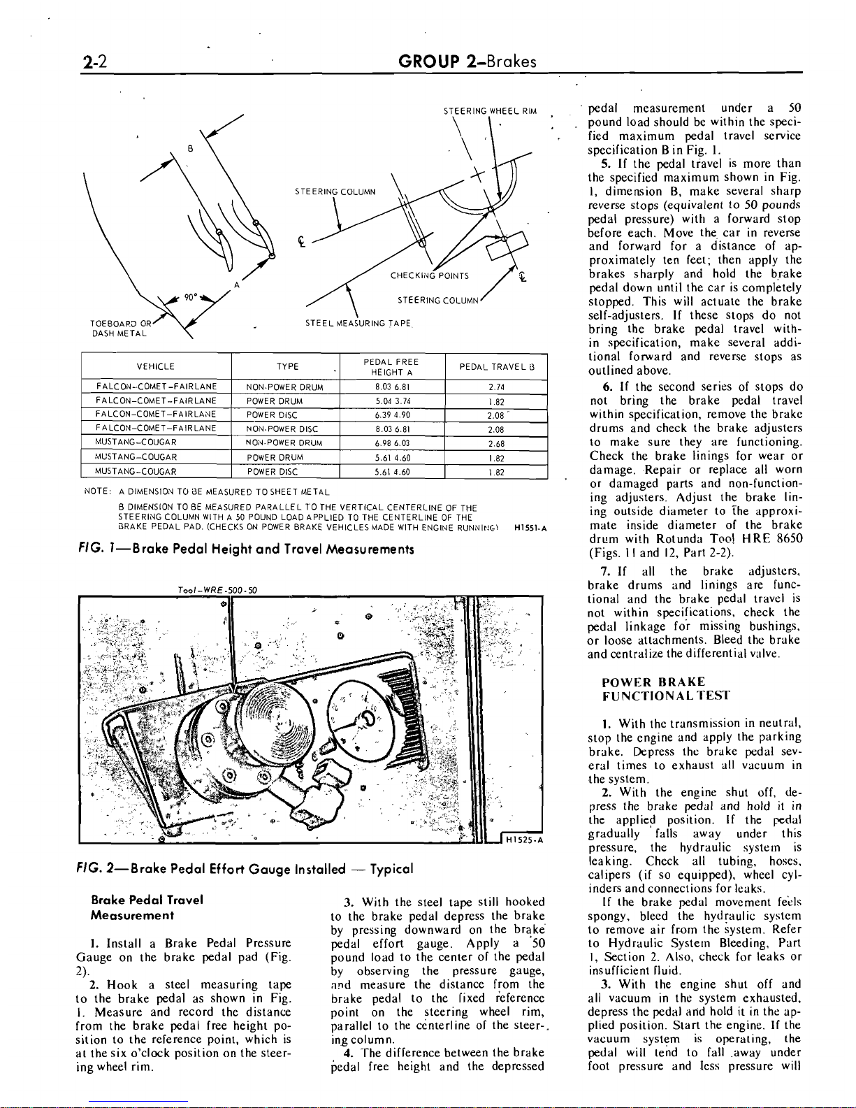
STEERING WHEEL RIM
NOTE: A DIMENSION TO
i3E MEASURED TO SHEET METAL
B DIMENSION TO BE MEASURED PARALLEL
70
THE VERTICAL CENTERLINE
OF
THE
STEERING COLUMN
WlTH A
50
POUND LOAD APPLIED TO THE CENTERLINE OF THE
BRAKE PEDAL PAD. (CHECKS ON POWER BRAKE VEHICLESMADE
WlTH ENGINE RUNNIP4C-l
H1551-~
FIG. I-Brake Pedal Height and Travel Measurements
FIG. 2-Brake Pedal
Effort
Gauge Installed - Typical
Brake Pedal Travel
Measurement
1.
Install a Brake Pedal Pressure
Gauge on the brake pedal pad (Fig.
2).
2.
Hook a steel measuring tape
to the brake pedal as shown in Fig.
I. Measure and record the distance
from the brake pedal free height position to the reference point, which is
at the six o'clock position on the steer-
ing wheel rim.
3.
With the steel tape still hooked
to the brake pedal depress the brake
by pressing downward on the
brake
pedal effort gauge. Apply a 50
pound load to the center of the pedal
by observing the pressure gauge,
agd measure the distance ffom the
brake pedal to the fixed reference
point on the steering wheel rim,
parallel to the ccnterline of the steer-.
ing column.
4.
The difference between the brake
pedal free height and the depressed
pedal measurement under a 50
pound load should be within the specified maximum pedal travel service
specification B in Fig.
1.
5.
If
the pedal travel is more than
the specified maximum shown in Fig.
I,
dimemion B, make several sharp
reverse stops (equivalent to 50 pounds
pedal pressure) with a forward stop
before each. Move the, car in reverse
and forward for a distance of approximately ten feet; then apply the
brakes sharply
and hold the brake
pedal down until the car is completely
stopped. This will actuate the brake
self-adjusters.
If
these stops do not
bring the brake pedal travel with-
in specification, make several additional forward and reverse stops as
outlined above.
6.
If
the second series of stops do
not bring the brake pedal travel
within specification, remove the brake
drums and check the brake adjusters
to make sure they are functioning.
Check the brake linings for wear or
damage. Repair or replace all worn
or damaged parts and
non-functioning adjusters. Adjust the brake lining outside diameter to The approximate inside diameter of the brake
drlrm wi!h Rotunda Too! HRE 8650
(Figs.
I I and 12, Part 2-2).
7.
If all the brake adjusters.
brake drums and linings are functional and the brake pedal travel is
not within specifications, check the
pedal linkage for missing bushings.
or loose attachments. Bleed the brake
and centralize the differential valve.
POWER BRAKE
FUNCTIONAL TEST
I.
With the transmission in neutral.
stop the engine and apply the parking
brake. Depress the brake pedal sev-
eral times to exhaust all vacuum in
the system.
2.
With the engine shut off. depress the brake pedal and hold it in
the applied position.
If
the pedal
gradually falls away under this
pressure, the hydraulic
system is
leaking. Check all tubing, hoses.
calipers (if so equipped), wheel cyl-
inders and connections for leaks.
If
the brake pedal movement f&ls
spongy, bleed the hydfaulic system
to remove air
from the system. Refer
to Hydraulic Systern Bleeding, Part
1, Section 2. Also, check for leaks or
insufficient fluid.
3.
With the engine shut off and
all vacuum in the system exhausted,
depress the pedal arid hold it in the applied position. Start the engine.
If
the
vacuum system is operating, the
pedal will tend to fall .away under
foot pressure and less pressure will
Page 11
PART
2-1-General Brake Service 2-3
be required to hold the pedal in the
applied position.
If
no action is felt,
the vacuum booster system is not
functioning.
LOCKED WHEEL BRAKE
Should one of the wheel brakes be
locked and the car must
be
moved,
open the bleeder screw long enough
to let out a few drops of brake fluid.
This bleeding operation
will
release
the brakes but will not correct the
cause of trouble.
PARKING BRAKE
Visually check the operation of the
parking brake linkage as the parking brake controls are moved to the
applied position. Then, check the operation of the brake linkage when the
parking brake controls are moved to
the released position. These checks
should indicate whether the manual
parking brake control linkage is operating properly or requires repair
or adjustment due to inability of the
parking brake to hold against moderate vehicle movement.
ROAD TEST
A
road test should
only
be con-
ducted when the operator is sure the
brakes
will
stop the vehicle.
During a road test, apply the ve-
hicles brakes at a road speed of 20
mph for all problem conditions listed
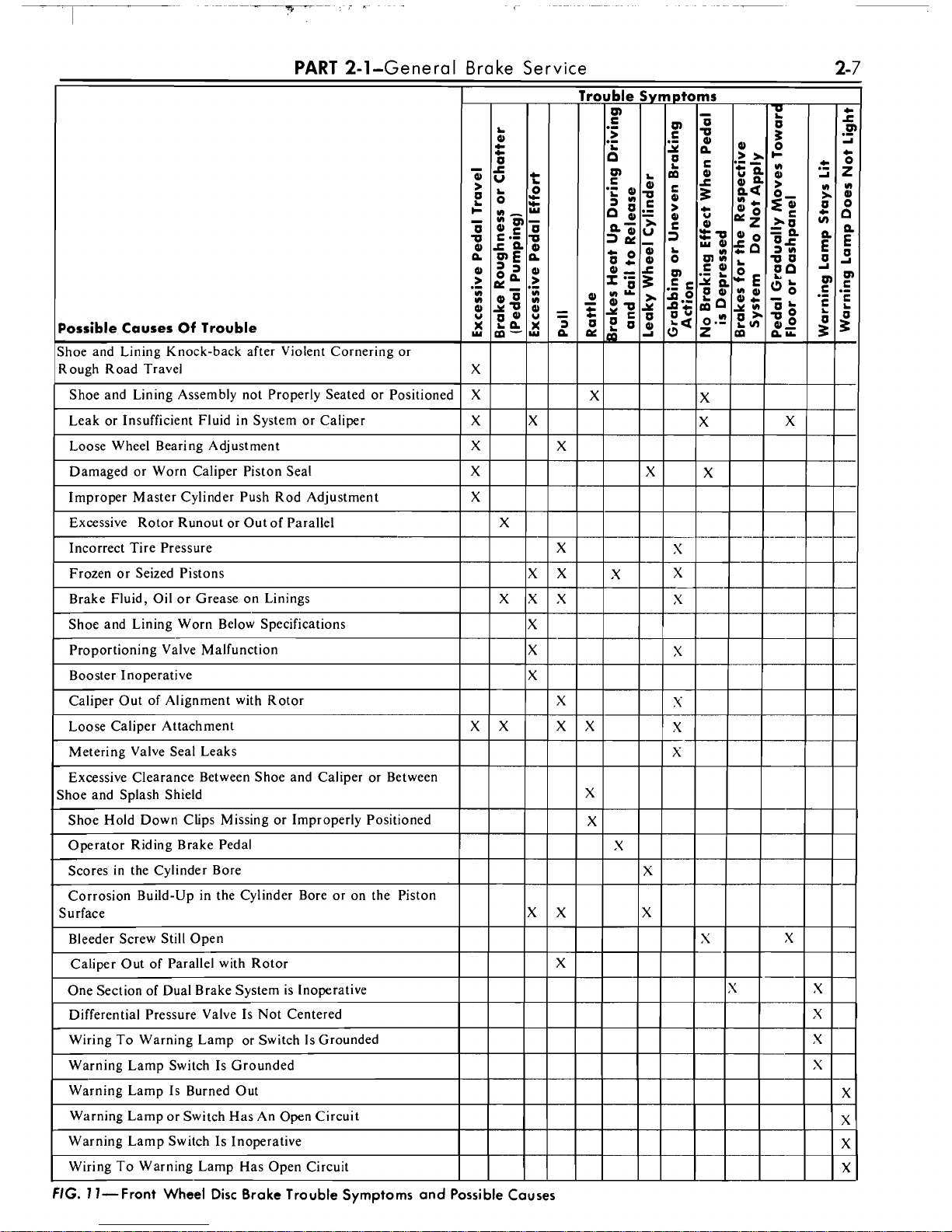
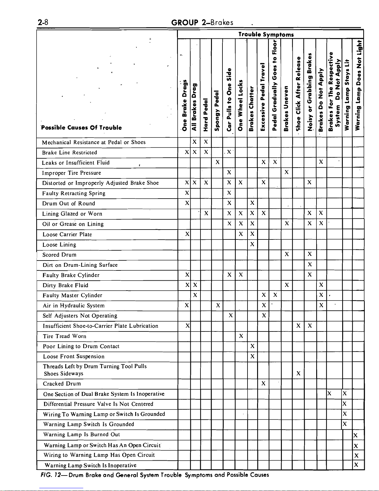
in Figs.
I I
and I2 with the excep-
tion of those resolved in the Brake System Tests and brake chatter. To check
for brake chatter or surge, apply the
brakes lightly at 50 mph. For each
of the symptoms encountered, check
and eliminate the causes which are
listed in Figs.
l
l
and 12.
If the road test reveals one or more
problem conditions listed in Figs.
11
and
12,
correct all malfunctions of
the vacuum system, brake booster
and hydraulic system prior to removing brake drums, brake calipers
(if so equipped), brake shoes and
linings or backing plates.
COMMON ADJUSTMENTS AND REPAIRS
PARKING BRAKE
LINKAGE ADJUSTMENT
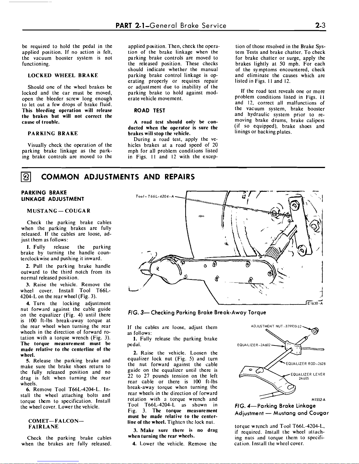
MUSTANG- COUGAR
Check the parking brake cables
when the parking brakes are fully
released.
If
the cables are loose, ad-
just them as follows:
I.
Fully release the parking
brake by turning the handle counterclockwise and pushing
it
inward.
2.
Pull the parking brake handle
outward to the third notch from its
normal released position.
3.
Raise the vehicle. Remove the
wheel cover. Install Tool
T66L-
4204-L on the rear wheel (Fig. 3).
4.
Turn the locking adjustment
nut forward against the cable guide
on the equalizer (Fig. 4) until there
is 100 ft-lbs break-away torque at
the rear wheel when turning the rear
wheels in the direction of forward rotation with a torque wrench (Fig. 3).
The torque measurement must be
made relative to the centerline of the
wheel.
5.
Release the parking brake and
make sure the brake shoes return to
the fully released position and no
drag is felt when turning the rear
wheels.
6.
Remove Tool T66L-4204-L. Install the wheel attaching bolts and
torque them to specification. Install
the wheel cover. Lower the vehicle.
COMET-FALCONFAIRLANE
Check the parking brake cables
when the brakes are fully released.
FIG. 3-Checking Parking Brake Break-Away Torque
If
the cables are loose, adjust them
as follows:
1.
Fully release the parking brake
pedal.
2.
Raise the vehicle. Loosen the
equalizer lock nut (Fig.
5)
and turn
the nut forward against the cable
guide on the equalizer until there is
22 to 27 pounds tension on the
left
rear cable or there is 100 ft-lbs
break-away torque when turning the
rear wheels in the direction of forward
rotation with
a
toraue wrench and
ADJUSTMENT NUT-37993062
EQUALIZER-2A602
EQUALIZER ROD-2628
H1552-A
Tool T66L-4204-L as shown in
FIG. 4-Parking Brake Linkage
Fig. 3.
The torque measurement
must be made relative
to
the center-
Adjustment - Mustang and Cougar
line of the wheel.
Tighten the lock nut.
torque wrench and Tool
T66L-4204-L,
3.
Make sure there is no drag
if
required, Install the wheel attach-
when turning the rear wheels.
inn nuts and torque them to specifi-
4.
Lower the vehicle. Remove the
cation. Install the wheel cover.
Page 12
\
CONVERTIBLE
NU'L
PARKING
ERAKE
CA:
AND
CONDUIT
,
ASSEMBLY-2853
\
,
SPRING-2A651
CAaLE
ASSEMSLY
,
A/
2A604
eRAKE
Y
RETAINER-74277.5
AND
CONDUIT
,
7-10
LB.FT.
\LR~'~AINER-~A~I~
CONVERTIBLE ONLY
H1553-A
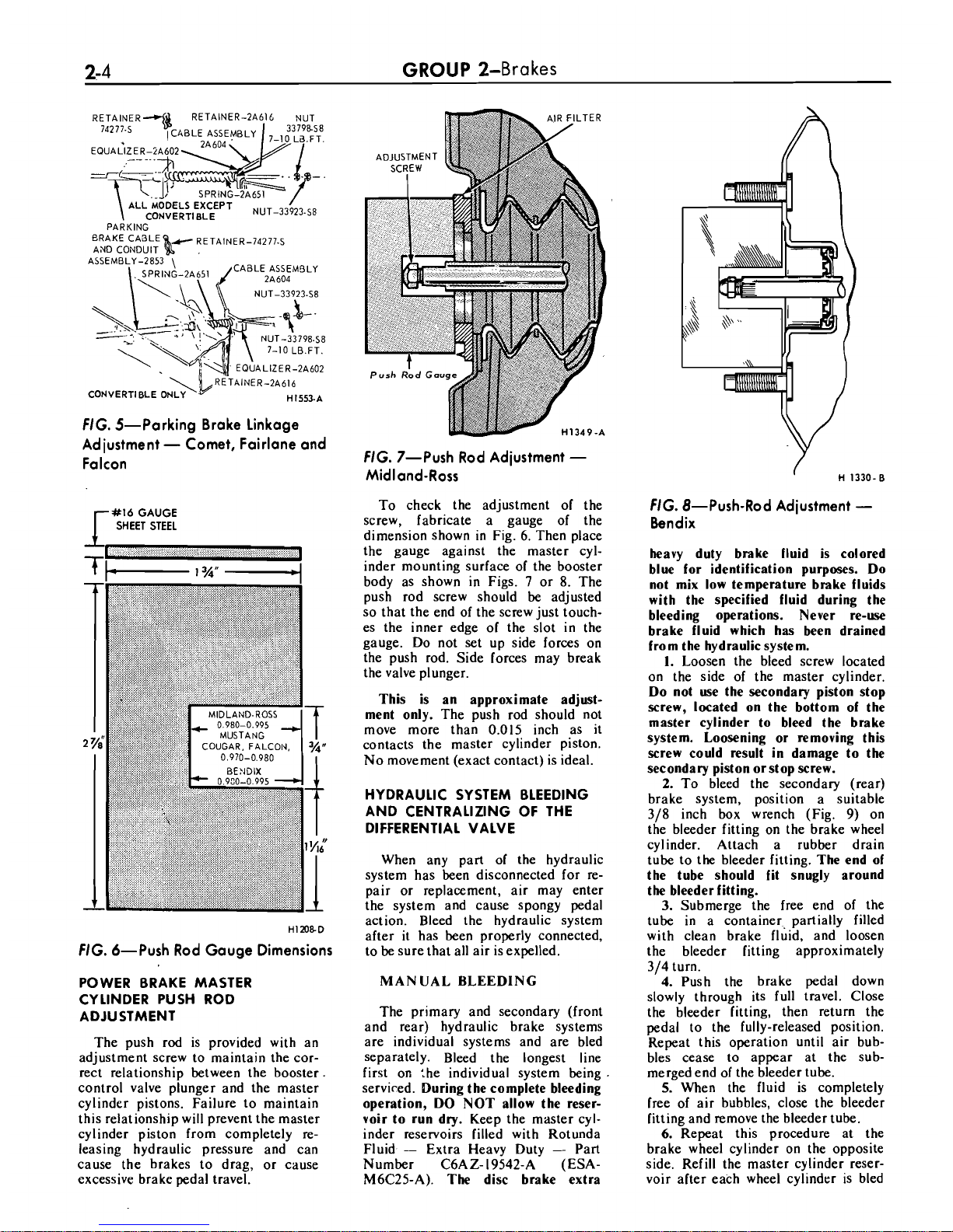
FIG.
5-Parking Brake Linkage
Adjustment
-
Comet, Fairlane and
Falcon
r
#16
GAUGE
SHEET STEEL
HIX)8-0
FIG.
6-Push Rod Gauge Dimensions
POWER BRAKE MASTER
CYLINDER PUSH ROD
ADJUSTMENT
The push rod is provided with an
adjustment screw to maintain the correct relationship between the booster.
control valve plunger and the master
cylinder pistons. Failure to maintain
this relationship will prevent the master
cylinder piston from completely releasing hydraulic pressure and can
cause the brakes to drag, or cause
excessive brake pedal travel.
GROUP
2-Brakes
FIG.
7-Push Rod Adjustment
-
Midland-Ross
To check the adjustment of the
screw, fabricate a gauge of the
dimension shown in Fig. 6. Then place
the gauge against the master cylinder mounting surface of the booster
body as shown in Figs.
7
or
8.
The
push rod screw should be adjusted
so that the end of the screw just touches the inner edge of the slot in the
gauge. Do not set up side forces on
the push rod. Side forces may break
the valve plunger.
This is an approximate adjust-
ment only.
The push rod should not
move more than 0.015 inch as it
contacts the master cylinder piston.
No movement (exact contact) is ideal.
HYDRAULIC SYSTEM BLEEDING
AND CENTRALIZING OF THE
DIFFERENTIAL VALVE
When any part of the hydraulic
system has been disconnected for repair or replacement, air may enter
the system and cause spongy pedal
action. Bleed the hydraulic system
after it has been properly connected,
to be sure that all air is expelled.
MAN
UAL
BLEEDING
The primary and secondary (front
and rear) hydraulic brake systems
are individual systems and are bled
separately. Bleed the longest line
first on
:he individual system being
serviced.
During the complete bleeding
operation, DO NOT allow the reservoir to run dry.
Keep the master cylinder reservoirs filled with Rotunda
Fluid
-
Extra Heavy Duty - Part
Number
C6AZ- 19542-A (ESA-
M6C25-A).
The
disc brake extra
FIG.
8-Push-Rod Adjustment
-
Bendix
heavy duty brake fluid is colored
blue for identification purposes.
Do
not mix low temperature brake fluids
with the specified fluid during the
bleeding operations. Never re-use
brake fluid which has been drained
from the hydraulic system.
I.
Loosen the bleed screw located
on the side of the master cylinder.
Do
not use the secondary piston stop
screw, located on the bottom of the
master cylinder to bleed the brake
system. Loosening or removing this
screw could result in damage to the
secondary piston or stop screw.
2.
To bleed the secondary (rear)
brake system, position a suitable
318
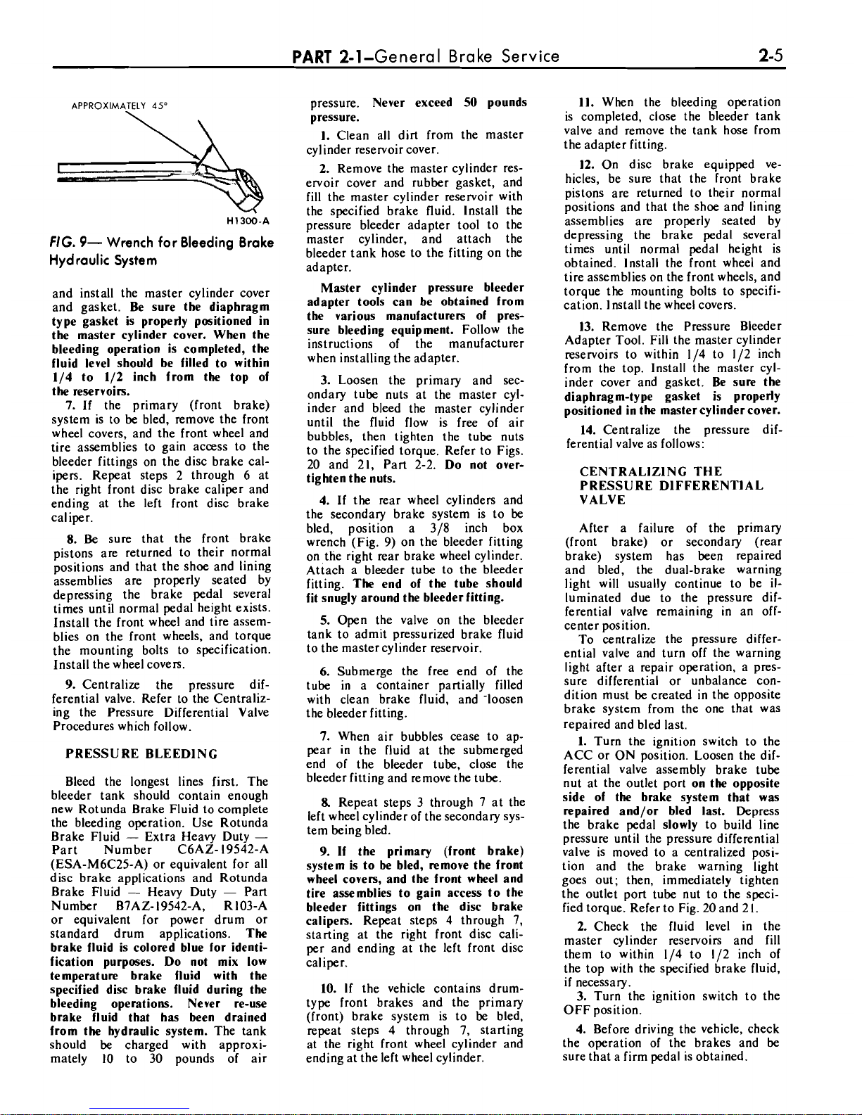
inch box wrench (Fig. 9) on
the bleeder fitting on the brake wheel
cylinder. Attach a rubber drain
tube to the bleeder fitting.
The end of
the tube should fit snugly around
the bleeder fitting.
3.
Submerge the free end of the
tube in a container, partially filled
with clean brake fluid, and loosen
the bleeder fitting approximately
314
turn.
4.
Push the brake pedal down
slowly through its full travel. Close
the bleeder fitting, then return the
pedal to the fully-released position.
Repeat this operation until air bub-
bles cease to appear at the submerged end of the bleeder tube.
5.
When the fluid is completely
free of air bubbles, close the bleeder
fitting and remove the bleeder tube.
6.
Repeat this procedure at the
brake wheel cylinder on the opposite
side. Ref
ill
the master cylinder reser-
voir after each wheel cylinder is bled
Page 13
PART
2-1-General Brake Service 2-5
APPROXIMATELY
45"
H1300-A
FIG.
9-
Wrench for Bleeding Brake
Hydraulic System
and install the master cylinder cover
and gasket. Be sure the diaphragm
type gasket is properly positioned in
the master cylinder cover. When the
bleeding operation is completed, the
fluid level should be filled to within
114 to 112 inch from the top of
the reservoirs.
7.
If the primary (front brake)
system is to be bled, remove the front
wheel covers, and the front wheel and
tire assemblies to gain access to the
bleeder fittings on the disc brake calipers. Repeat steps 2 through 6 at
the right front disc brake caliper and
ending at the left front disc brake
caliper.
8.
Be
sure that the front brake
pistons are returned to their normal
positions and that the shoe and lining
assemblies are properly seated by
depressing the brake pedal several
times until normal pedal height exists.
Install the front wheel and tire assemblies on the front wheels, and torque
the mounting bolts to specification.
Install the wheel covers.
9.
Centralize the pressure differential valve. Refer to the Centralizing the Pressure Differential Valve
Procedures which follow.
PRESSURE
BLEEDlNG
Bleed the longest lines first. The
bleeder tank should contain enough
new Rotunda Brake Fluid to complete
the bleeding operation. Use Rotunda
Brake Fluid
-
Extra Heavy Duty
-
Part Number C6AZ- 19542-A
(ESA-M6C25-A) or equivalent for all
disc brake applications and Rotunda
Brake Fluid
-
Heavy Duty - Part
Number
B7AZ- 19542-A, R103-A
or equivalent for power drum or
standard drum applications. The
brake fluid is colored blue for identi-
fication purposes. Do not mix low
temperature brake fluid with the
specified disc brake fluid during the
bleeding operations. Never re-use
brake fluid that has been drained
from the hydraulic system. The tank
should be charged with approxi-
mately 10 to 30 pounds of air
pressure. Never exceed 50 pounds
pressure.
1. Clean all dirt from the master
cylinder reservoir cover.
2. Remove the master cylinder reservoir cover and rubber gasket, and
fill
the master cylinder reservoir with
the specified brake fluid. Install the
pressure bleeder adapter tool to the
master cylinder, and attach the
bleeder tank hose to the fitting on the
adapter.
Master cylinder pressure bleeder
adapter tools can be obtained from
the various manufacturers of pressure bleeding equipment. Follow the
instructions of the manufacturer
when installing the adapter.
3. Loosen the primary and secondary tube nuts at the master cylinder and bleed the master cylinder
until the fluid flow is free of air
bubbles, then tighten the tube nuts
to the specified torque. Refer to Figs.
20 and 21, Part 2-2. Do not over-
tighten the nuts.
4. If the rear wheel cylinders and
the secondary brake system is to be
bled, position a
318 inch box
wrench (Fig. 9) on the bleeder fitting
on the right rear brake wheel cylinder.
Attach a bleeder tube to the bleeder
fitting. The end of the tube should
fit snugly around the bleeder fitting.
5. Open the valve on the bleeder
tank to admit pressurized brake fluid
to the master cylinder reservoir.
6.
Submerge the free end of the
tube in a container partially filled
with clean brake fluid, and -loosen
the bleeder fitting.
7.
When air bubbles cease to ap-
pear in the fluid at the submerged
end of the bleeder tube, close the
bleeder fitting and remove the tube.
8.
Repeat steps 3 through 7 at the
left wheel cylinder of the secondary system being bled.
9.
If the primary (front brake)
system is to be bled, remove the front
wheel covers, and the front wheel and
tire assemblies to gain access to the
bleeder fittings on the disc brake
calipers. Repeat steps 4 through 7,
starting at the right front disc caliper and ending at the left front disc
caliper.
10.
If
the vehicle contains drumtype front brakes and the primary
(front) brake system is to be bled,
repeat steps 4 through 7, starting
at the right front wheel cylinder and
ending at the left wheel cylinder.
11. When the bleeding operation
is completed, close the bleeder tank
valve and remove the tank hose from
the adapter fitting.
12. On disc brake equipped vehicles, be sure that the front brake
pistons are returned to their normal
positions and that the shoe and lining
assemblies are properly seated by
depressing the brake pedal several
times until normal pedal height is
obtained. Install the front wheel and
tire assemblies on the front wheels, and
torque the mounting bolts to specifi-
cation.
1
nstall the wheel covers.
13. Remove the Pressure Bleeder
Adapter Tool. Fill the master cylinder
reservoirs to within
114 to 112 inch
from the top.
lnstall the master cylinder cover and gasket. Be sure the
diaphragm-type gasket is properly
positioned in the master cylinder cover.
14. Centralize the pressure dif-
ferential valve as follows:
CENTRALlZlNG THE
PRESSURE DIFFERENTIAL
VALVE
After a failure of the primary
(front brake) or secondary (rear
brake) system has been repaired
and bled, the dual-brake warning
light will usually continue to be
il-
luminated due to the pressure dif-
ferential valve remaining in an
off-
center position.
To centralize the pressure differ-
ential valve and turn off the warning
light after a repair operation, a pres-
sure differential or unbalance condition must
be
created in the opposite
brake system from the one that was
repaired and bled last.
1. Turn the ignition switch to the
ACC or ON position. Loosen the differential valve assembly brake tube
nut at the outlet port on the opposite
side of the brake system that was
repaired and/or bled last. Depress
the brake pedal slowly to build line
pressure until the pressure differential
valve is moved to a centralized position and the brake warning light
goes out; then, immediately tighten
the outlet port tube nut to the specified torque. Refer to Fig. 20 and 2
I.
2. Check the fluid level in the
master cylinder reservoirs and
fill
them to within 114 to 112 inch of
the top with the specified brake fluid,
if
necessary.
3.
Turn the ignition switch to the
OFF position.
4. Before driving the vehicle, check
the operation of the brakes and
be
sure that a firm pedal is obtained.
Page 14
GROUP
2-Bra
kes
CLEANING AND INSPECTION
DISC (FRONT) BRAKES
1.
Remove the wheel and tire, caliper splash shield, and the shoe and lining assemblies as outlined in Part
2-2, Section 2.
2.
Make three thickness measurements with a micrometer across the
middle section of the shoe and lining.
Take one reading at each side and
one in the center. If the assembly has
worn to
'a thickness of 0.231 inch
(shoe and lining together) or 0.066
inch (lining material only) at any
one of the three measuring locations
or
if
the brake lining shows evidence
of brake fluid contamination, replace all four shoe and lining as-
semblies on both front wheels.
3.
Check the caliper to spindle
attaching bolt and caliper bridge
bolt torque. Tighten them to the
specified torque,
if
required.
4.
To check rotor runout, first
eliminate the wheel bearing end play
by tightening the adjusting nut.
After tightening the nut check to see
that the rotor can still be rotated.
5.
Clamp a dial indicator to the
caliper housing so that the stylus
contacts the rotor at a point approximately
I
inch from the outer edge.
Rotate the rotor and take an indica-
tor reading.
If
the reading exceeds
0.002 inch total lateral
runout on
the indicator, replace or resurface
the disc brake rotor.
The following
requirements must be met when re-
surfacing disc brake rotors:
Rotunda Disc Brake Attachment
FRE-2249-2 is the
only approved
tool
to
be
used to refinish the disc
brake rotors. The step-by-step resurfacing procedure provided with the
tool must be adhered to.
The finished braking surfaces of
the rotor must be flat and parallel
within 0.0007 inch; lateral
runout
must not exued 0.002 inch total
indicator reading, and the surface
finish of the braking surfaces are
to
be
85/15 micro inches.
The min-
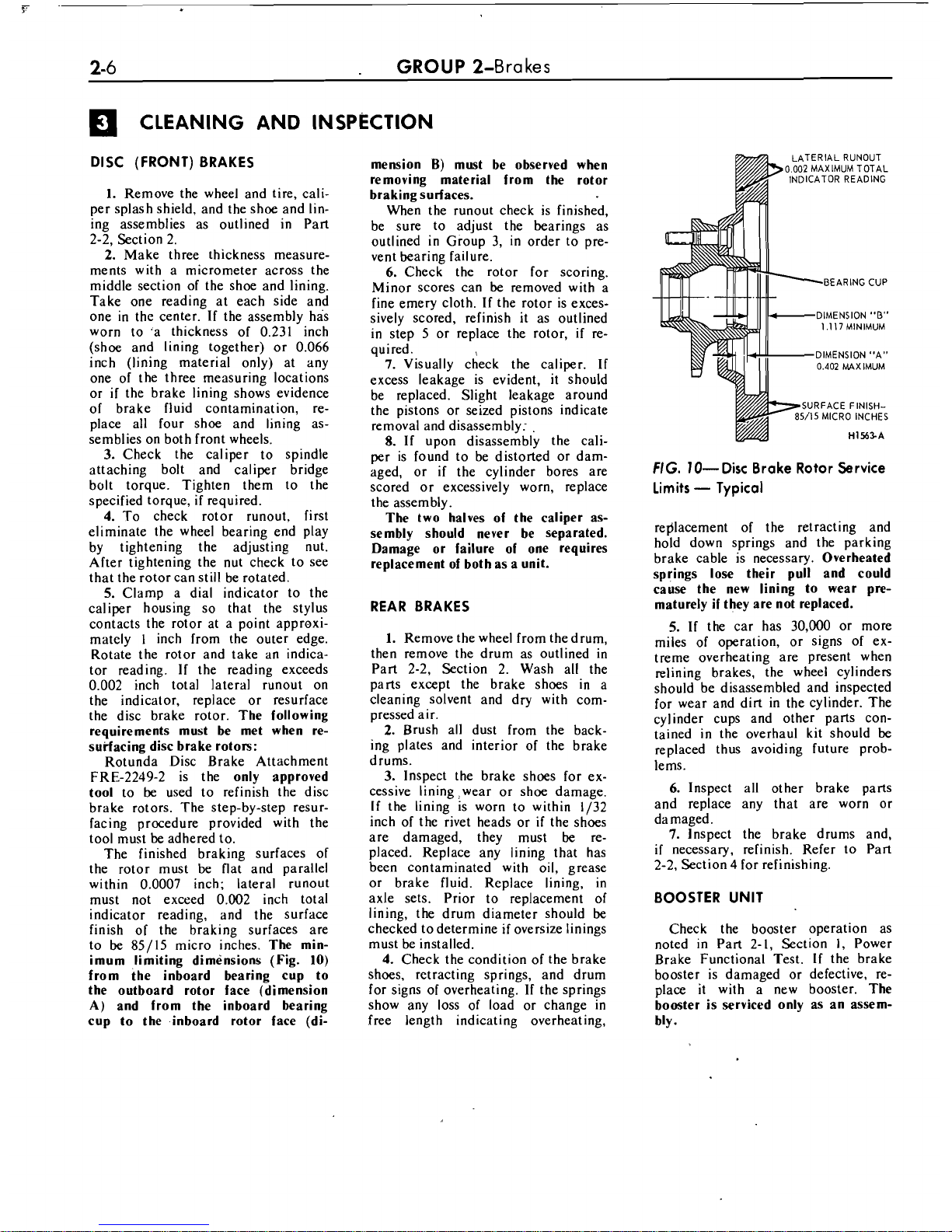
imum limiting dimensions (Fig.
10)
from the inboard bearing cup to
the outboard rotor face (dimension
A)
and from the inboard bearing
cup to the inboard rotor face (di-
mension
B)
must be observed when
removing material from the rotor
braking surfaces.
When the runout check is finished,
be sure to adjust the bearings as
outlined in Group
3,
in order to pre-
vent bearing failure.
6.
Check the rotor for scoring.
Minor scores can be removed with a
fine emery cloth. If the rotor is exces-
sively scored, refinish it as outlined
in step 5 or replace the rotor,
if
re-
quired.
7.
Visually check the caliper. If
excess leakage is evident, it should
be replaced. Slight leakage around
the pistons or seized pistons indicate
removal and disassembly:
.
8.
If upon disassembly the cali-
per is found to be distorted or damaged, or
if
the cylinder bores are
scored or excessively worn, replace
the assembly
.
The two halves of the caliper assembly should never be separated.
Damage or failure of one requires
replacement of both as a unit.
REAR BRAKES
1.
Remove the wheel from the drum,
then remove the drum as outlined in
Part 2-2, Section 2. Wash all the
parts except the brake shoes in a
cleaning solvent and dry with com-
pressed air.
2.
Brush all dust from the back-
ing plates and interior of the brake
drums.
3.
Inspect the brake shoes for ex-
cessive lining
:wear or shoe damage.
If
the lining is worn to within 1/32
inch of the rivet heads or
if
the shoes
are damaged, they must
be
replaced. Replace any lining that has
been contaminated with oil, grease
or brake fluid. Replace lining, in
axle sets. Prior to replacement of
lining, the drum diameter should
be
checked to determine
if
oversize linings
must be installed.
4.
Check the condition of the brake
shoes, retracting springs, and drum
for signs of overheating. If the springs
show any loss of load or change in
free length indicating overheating,
LATERIAL RUNOUT
0.002
MAXIMUM TOTAL
INDICATOR READING
BEARING CUP
DIMENSION
"B"
1.117
MINIMUM
DIMENSION "A"
0.402
MAXIMUM
SURFACE
FINISH-
/IS
MICRO INCHES
H1%3-A
FIG.
10-Disc Brake Rotor Service
Limits
-
Typical
replacement of the retracting and
hold down springs and the parking
brake cable is necessary.
Overheated
springs lose their pull and could
cause the new lining to wear pre-
maturely if they are not replaced.
5.
If the car has 30,000 or more
miles of operation, or signs of ex-
treme overheating are present when
relining brakes, the wheel cylinders
should be disassembled and inspected
for wear and dirt in the cylinder. The
cylinder cups and other parts contained in the overhaul kit should be
replaced thus avoiding future problems.
6.
Inspect all other brake parts
and replace any that are worn or
damaged.
7.
Inspect the brake drums and,
if
necessary, refinish. Refer to Part
2-2,
Section 4 for refinishing.
BOOSTER UNIT
Check the booster operation as
noted in Part 2-1, Section
1, Power
Brake Functional Test.
If
the brake
booster is damaged or defective, replace it with a new booster.
The
booster is serviced only
as
an assembly.
Page 15
-
PART
2-1-General Brake Service
FIG.
I
I-Front Wheel Disc Brake Trouble Symptoms and Possible Causes
Trouble Symptoms
m
3
C
c
.-
t
>
C
.-
C
ii
0
-=
+
m
LO
r
II),m
m
Possible Causes
Of
Trouble
Shoe and Lining Knock-back after Violent Cornering or
Rough Road Travel
Shoe and Lining Assembly not Properly Seated or Positioned
Leak or Insufficient Fluid in System or Caliper
Loose Wheel Bearing Adjustment
Damaged or Worn Caliper Piston Seal
Improper Master Cylinder Push Rod Adjustment
Excessive Rotor
Runout or Out of Parallel
Incorrect Tire Pressure
Frozen or Seized Pistons
Brake Fluid, Oil or Grease on Linings
Shoe and Lining Worn Below Specifications
Proportioning Valve Malfunction
Booster Inoperative
Caliper Out of Alignment with Rotor
Loose Caliper Attachment
Metering Valve Seal Leaks
Excessive Clearance Between Shoe and Caliper or Between
Shoe and Splash Shield
Shoe Hold Down Clips Missing or Improperly Positioned
Operator Riding Brake Pedal
Scores in the Cylinder Bore
Corrosion Build-Up in the Cylinder Bore or on the Piston
X
X
X
X
X
X
X
Differential Pressure Valve Is Not Centered
X
X
X
Wiring To Warning Lamp or Switch Is Grounded
Warning Lamp Switch Is Grounded
Warning Lamp Is Burned Out
Warning Lamp or Switch Has An Open Circuit
Warning Lamp Switch Is Inoperative
Wiring To Warning Lamp Has Open Circuit
X
X
X
X
X
X
.Y
S
X
X
X
X
X
?(
X
X X X
X
X
X
?(
X
X
X
X
X
X
X'
.Y
>i
X
X
X
.-
--
-
-
-
X
--
Page 16
2-8
GROUP
2-Bra
kes
Trouble Symptoms
t
C
z
0
-
P
Y
.-
4)
4
al
2
-
r
r
-
'Possible Causes
Of
Trouble
Mechanical Resistance at Pedal or Shoes
X
X
I
IIIII
I
I
Warning Lamp Switch Is Inoperative
1
IIIII
111
111
I
X
FIG.
12-Drum Brake and General System Trouble Symptoms and Possible Causes
Page 17
I
Section Page
..........................
1
Description and Operation 2-9
...........
Dual-Master Cylinder Brake System 2-9
Disc Brakes
...........................................
2-1
1
Hydraulic Self-Adjusting Brake System
........
2-13
Booster System
.....................................
.2-13
Parking Brakes
......................................
2-14
2
In-Vehicle Adjustments and Repairs
..............
2-14
Front (Disc) Brake Shoe and Lining
Replacement
.......................................
2-17
Disc Brake Caliper Assembly
....................
2-18
.......
Front Wheel Hub and Rotor Assembly
2-18
Disc Brake Rotor Splash Shield
.................
2-19
Proportioning Valve..
..............................
2-19
........
Brake Shoe Adjustments-Rear Wheels 2-16
Rear Brake Drum.
..................................
2-20
Rear Brake Shoe Replacement
.................
.2-20
Rear Wheel Cylinder Repair
.....................
2-19
Rear Wheel Cylinder Replacement
.............
2-19
Rear Brake Backing Plate Replacement
.......
2-20
Hydraulic Lines
....................................
2-20
Section Page
Brake Tube Replacement
......................
2-20
Brake Hose Replacement
......................
2-20
3
Removal and Installation
............................
2-23
Dual Master Cylinder
-
Standard Brakes
......
2-23
Dual-Master
Cylinder-Power Brakes
.........
2-24
Pressure Differential Valve Assembly
..........
2-24
Brake Booster
........................................
2-25
Brake Pedal
...........................................
2-25
Parking Brake Control Assembly
...............
2-26
Parking Brake Equalizer to Control
Cable
....................................................
.2-26
Parking Brake Equalizer to Rear Wheel
Cable
................................................
2-27
............................
4
Major Repair Operations 2-28
Brake Drum Refinishing
..........................
2-28
Rotor Refinishing
...................................
2-28
Brake Shoe Relining
...............................
2-29
Dual-Master Cylinder
..............................
2-29
Disc Brake Caliper
................................
.2-30
DESCRIPTION AND
Disc brakes are available as op-
tional equipment for the front wheels
on the various vehicle models listed
in (Fig. I).
The dual-master cylinder equipped
hydraulic brake system employes
single-anchor, internal expanding and
self-adjusting drum brake assemblies
on the rear wheels of vehicles with
disc brakes, and on the front and rear
wheels of all others (Fig.
1).
DUAL-MASTER CYLINDER
BRAKE SYSTEM
The dual-master cylinder brake sys-
tem has been incorporated in all car
models to provide increased vehicle
safety. The system consists of a dualmaster cylinder, pressure differential
valve assembly and a switch. The
switch on the differential valve activates a dual-brake system warning
light, located on the instrument panel.
The dual-master cylinder brake sys-
tem is similar to a conventional
(single) brake master cylinder system. In the dual-system, two master
cylinders are combined in a single
cast iron casting (Fig. 2). One portion actuates the front brake system
and the other actuates the rear brake
system (Figs. 20 and 21). Hydraulic
fluid leakage or failure of one of
the systems does not impair the operation of the other portion of the dualbrake system. A dual-brake warning
light signals a failure of either the
front or rear brake system.
OPERATION
The dual-master cylinder used on
Fairlane, Falcon and Comet vehicles
equipped with power brakes have the
master cylinder outlet ports for the
rear brake system located on the bottom of the master cylinder body.
Master cylinder hydraulic system
bleed screws are located in the outboard side of those master cylinders
having secondary (rear brake) system
outlet ports in the bottom of the master cylinder castings (Fig. 29).
All Fairlane, Falcon and Comet ve-
hicles equipped with standard drum
brakes and all Mustang and Cougar
vehicles equipped with power disc,
power drum and standard drum
brakes have both the primary (front)
and secondary (rear) brake system
outlet ports located on the outboard
side of the dual-master cylinder body
castings. These master cylinders do
not require master cylinder bleed
screws (Figs. 27, 28 and 30).
The external appearance of the dual
master cylinders for the various vehicles also differ in configuration
of the covers. All vehicles having
standard drum brake systems and
Mustang, Cougar vehicles equipped
with power drum brakes have primary
and secondary master cylinder cover
domes of equal size. Dual master cyl-
inders for all other vehicles equipped
with power disc and power drum
brake systems have large primary
(front brake) and smaller secondary
(rear brake) cover domes.
A code letter is stamped on the
side or outer end of each master cylinder body casting for easy service
identification. The vehicle application,
type of brakes and the identification
code are shown in Fig. 3.
A brake pressure differential valve
assembly (Fig.
4)
incorporating an hydraulically operated mechanical
switch is utilized to operate a dualbrake warning light, located on the
instrument panel.
Hydraulic pressure for both front
wheel brakes is provided from the primary system (front) brake outlet port
and line, located opposite the primary
system inlet port of the differential
valve.
Hydraulic pressure for both rear
wheel brakes is provided from the single secondary (rear brake) outlet
line, located opposite the secondary
system inlet port of the differential
valve. On disc brake equipped vehicles, a proportioning valve is located
in the secondary (rear brake) system
line that leads to the brake hose
bracket on the rear axle housing. The
brake hose bracket serves as a junction point for the individual brake
lines that lead to the wheel cylinders
of right and left rear brake components.
When the brake pedal is depressed,
both the primary (front brake) and
Page 18
GROUP
2-Bra
kes
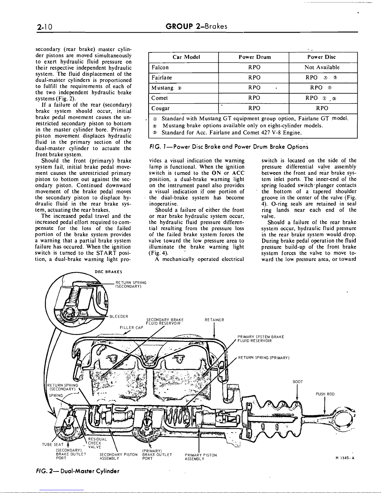
secondary (rear brake) master cylinder pistons are moved simultaneously
to exert hydraulic fluid pressure on
their respective independent hydraulic
system. The fluid displacement of the
duallmaster cylinders is proportioned
to fulfill the requirements of, each of
the two independent hydraulic brake
systems (Fig. 2).
If a failure of the rear (secondary)
brake system should occur, initial
brake pedal movement causes the unrestricted secondary piston to bottom
in the master cylinder bore. Primary
piston movement displaces hydraulic
fluid in the primary section of the
dual-master cylinder to actuate the
front brake system.
Should the front (primary) brake
system fail, initial brake pedal move-
ment causes the unrestricted primary
piston to bottom out against the sec-
ondary piston. Continued downward
movement of the brake pedal moves
the secondary piston to displace hydraulic fluid in the rear brake system, actuating the rear brakes.
The increased pedal travel and the
increased pedal effort required to com-
pensate for the loss of the failed
portion of the brake system provides
a warning that a partial brake system
failure has occured. When the ignition
switch is turned to the START position, a dual-brake warning light
pro-
FIG.
I-Power Disc Brake and Power Drum Brake Options
Car Model
Falcon
Fairlane
Mustang
Zi
Comet
Cougar
vides a visual indication the warning
lamp is functional. When the ignition
switch is turned to the
ON
or ACC
position, a dual-brake warning light
on the instrument panel also provides
a visual indication
if
one portion of
the dual-brake system has become
inoperative.
Should a failure of either the front
or rear brake hydraulic system occur,
the hydraulic fluid pressure differential resulting from the pressure loss
of the failed brake system forces the
valve toward the low pressure area to
illuminate the brake warning light
(Fig: 4).
A
mechanically operated electrical
switch is located on the side of the
pressure differential valve assembly
between the front and rear brake system inlet ports. The inner-end of the
spring loaded switch-plunger contacts
the bottom of a tapered shoulder
groove in the center of the valve (Fig.
4). O-ring seals are retained in seal
ring lands near each end of the
valve.
Should a failure
of the rear brake
system occur, hydraulic fluid pressure
in the rear brake system would drop.
During brake pedal operation the fluid
pressure build-up of the front brake
system forces the valve to move toward the low pressure area, or toward
3
Standard with Mustang GT equipment group option, Fairlane GT model.
Mustang brake options available only on eight-cylinder models.
3
Standard for Acc. Fairlane and Comet 427
V-8
Engine,
Power Drum
RPO
RPO
RPO
.
RPO
RPO
FIG.
2-
Dual-Master Cylinder
Power Disc
Not Available
RPO
3
B
RPO
@
RPO
3
.
o
RPO
Page 19

PART
2-2-Brake System
2-1
1
the rear brake system outlet port (Fig.
4).
Movement of the differential valve
forces the switch plunger upward over
the tapered shoulder of the valve to
close the switch electrical contacts and
light the dual brake warning lamp,
signalling a brake system failure.
In the event a front brake system
failure should occur, greater pressure
from the rear brake system during
brake pedal operation forces the valve
forward, moving the switch plunger
upward onto the valve ramp to light
the brake system warning lamp. However, failure of either the front or
rear system does not impair operation
of the
other brake system.
DISC BRAKE ASSEMBLIES
Disc brakes are available as op-
tional equipment for the front wheels.
The hydraulic brake system employs
single
-anchor, internal expanding and
self-adjusting drum brake assemblies
on the rear wheels of vehicles with
disc brakes, and on the front and rear
wheels of all others.
A
vacuum booster is available as
optional equipment.
The master cylinder converts physical force from the brake pedal (and
booster if so equipped) into hydraulic
pressure against the pistons in the
I
calipers (disc brakes) or in the wheel
Car Model Type Of Brake
Identifiation Code
Power Disc
B
Fairlane and Falcon Power Drum S
Standard Drum T
Power Disc M
Mustang Power Drum
X
Standard Drum T
Comet Power Disc
B
Power Drum
S
Standard Drum T
Cougar Power Disc M
Power Drum
X
Standard Drum T
FIG. 3-Dual Master Cylinder Identification
cylinders (drum brakes). The pistons
in turn convert hydraulic pressure
back into physical force at the brake
shoes.
RELATION AND FUNCTION
OF COMPONENT PARTS
The disc brake is a fixed caliper,
opposed piston, non-energized, venti-
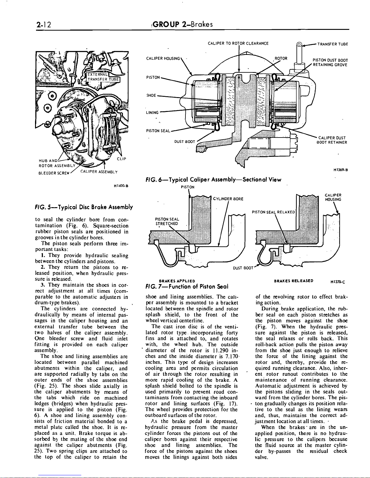
lated disc type, actuated by a hydraulic system (Fig. 5). There is no
lateral movement of either the disc
(rotor) or the caliper. The caliper
assembly consists of two caliper
housings bolted together with each
half containing two cylinder bores
of
1 15/16 inch diameter. Each cyl-
inder bore contains a piston with an
attached molded rubber dust boot
I
BRAKE WARNIFIS LAMP SWITCH BRAKE WARNING LAMP SWITCH
I
VALVE PISTON HAS MOVED TO LOW PRESSURE AREA.
VALVE PISTON
;S
CENTRALIZED.
WARNING LAMP SWITCH PLUNGER IS DEPRESSED,
BRAKE
FLUID
PRIMARY AND SECONDARY SYSTEM
LIGHTING THE BRAKE WARNING LAMP PRESSURES ARE EQUALIZED
H1471-A
FIG. 4-Pressure Differential Valve and Brake Warning Lamp Switch Operation
Page 20
CALIPER
TO
ROTOR
CLEARANCE
I
WTRANSFER
TUBE
FIG.
5-Typical Disc Brake Assembly
to seal the cylinder bore from con-
tamination (Fig. 6). Square-section
rubber piston seals are positioned in
grooves in the cylinder bores.
The piston seals perform three im-
portant tasks:
1.
They provide hydraulic sealing
between the cylinders and pistons.
2.
They return the pistons to released position, when hydraulic pressure is released.
3.
They maintain the shoes in cor-
rect adjustment at all times (comparable to the automatic adjusters in
drum-type brakes).
The cylinders are connected hydraulically by means of internal passages in the caliper housing and an
external transfer tube between the
two halves of the caliper assembly.
One bleeder screw and fluid inlet
fitting is provided on each caliper
assembly.
The shoe and lining assemblies are
located between parallel machined
abutments within the caliper, and
are supported radially by tabs on the
outer ends of the shoe assemblies
(Fig. 25). The shoes slide axially in
the caliper abutments by means of
the tabs which ride on machined
ledges (bridges) when hydraulic pres-
sure is applied to the piston (Fig.
6). A shoe and lining assembly consists of friction material bonded to a
metal
platc called the shoe. It is replaced as a unit. Brake torque is absorbed by the mating of the shoe end
against the caliper abutments (Fig.
25). Two spring clips are attached to
the top of the caliper to retain the
FIG.
6-Typical Caliper Assembly-Sectional View
PISTON
1
BRAKES APPLIED
FIG.
7-Function of Piston Seal
shoe and lining assemblies. The caliper assembly is mounted to a bracket
located between the spindle and rotor
splash shield, to the front of the
wheel vertical centerline.
The cast iron disc is of the ventilated rotor type. incorporating forty
fins and is attached to, and rotates
with, the wheel hub. The outside
'
diameter of the rotor is 11.290 in-
ches and the inside diameter is 7.170,
inches. This type of design increases
cooling area and permits circulation
of air through the rotor resulting in
-
more rapid cooling of the brake. A
splash shield bolted to the spindle is
used primarily to prevent road con-
taminants from contacting the inboard
rotor and lining surfaces (Fig. 17).
The wheel provides protection for the
outboard surfaces of the rotor.
As the brake pedal is depressed,
hydraulic pressure from the master
cylinder forces the pistons out of the
caliper bores against their respective
shoe and lining assemblies. The
force of the pistons against the shoes
moves the linings against both sides
BRAKES RELEASED
til3m~
of the revolving rotor to effect brak-
ing action.
During brake application, the rubber seal on each piston stretches as
the piston moves against the shoe
(Fig. 7). When the hydraulic pres-
sure against the piston is released,
the seal relaxes or rolls back. This
roll-back action pulls the piston away
from the shoe just enough to relieve
the force of the lining against the
rotor and, thereby, provide the re-
quired running clearance. Also, inherent rotor
runout contributes to the
maintenance of running clearance.
Automatic adjustment is achieved by
the pistons sliding in the seals outward from the cylinder bores. The piston gradually changes its position relative to the seal as the lining wears
and, thus, maintains the correct ad-
justment location at all times.
-
When the brakes- are in the unapplied position, there is no hydraulic pressure to the calipers because
the fluid source at the master cylinder by-passes the residual check
valve.
Page 21
PART
2-2-Brake System 2-1
3
CLIP MUST NOT TOUCH OR COVER
RUBBER
RING AROUND OUTSIDE
OF VALVE
ASS,EMBLY
A
DlSC BRAKE PRESSURE
CONTROL VALVE
ASSEMBLY-ZBOPI B0LT-376459-S2
INSTALLATION-DISC BRAKES ONLY
TUBE-2265
TORQUE TO 6.15 LB. FT.
DlSC BRAKE CONTROL
TUBE-2265
PROPORTIONING VALVE
I
ASSEMBLY-26272 TUBE-2B113
FLAT SlDE 0F"D" SHAPED HOLE
MUST BE LOCATED ON INBOARD
SlDE OF HOSE BRACKET
HOSE-2A448
BOLT-376459.52
INSTALLATION-DISC BRAKES SAME AS
INSTALLATION-DISC
i3RAKE ALTERNATE ONLY
MAIN VIEW EXCEPT AS SHOWN
H1561-A
NG.
8-Disc Brake Pressure Control Valve
REAR BRAKE
NG.
9-Self-Adjusting Brake Assemblies-9 Inch Drum
A
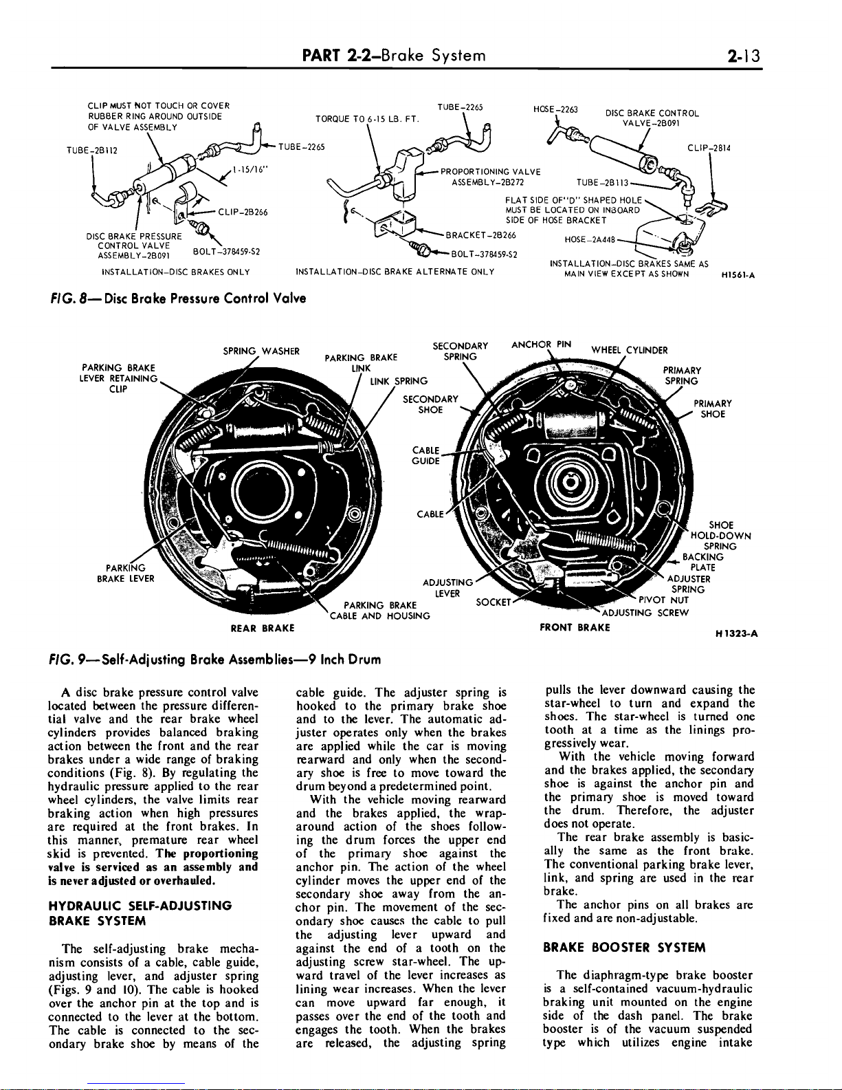
disc brake pressure control valve
located between the pressure differential valve and the rear brake wheel
cylinders provides balanced braking
action between the front and the rear
brakes under a wide range of braking
conditions (Fig.
8).
By regulating the
hydraulic pressure applied to the rear
wheel cylinders, the valve limits rear
braking action when high pressures
are required at the front brakes. In
this manner.
Dremature rear wheel
skid is
prevdnied.
The
proportioning
valve is serviced as an
assemblv and
is never adjusted or overhauled.
HYDRAULIC SELF-ADJUSTING
BRAKE SYSTEM
The self-adjusting brake mechanism consists of a cable, cable guide,
adjusting lever, and adjuster spring
(Figs.
9
and 10). The cable is hooked
over the anchor pin at the top and is
connected to the lever at the bottom.
The cable is connected to the secondary brake shoe by means of the
cable guide. The adjuster spring is
hooked to the primary brake shoe
and to the lever. The automatic adjuster operates only when the brakes
are applied while the car is moving
rearward and only when the secondary shoe is free to move toward the
drum beyond a predetermined point.
With the vehicle moving rearward
and the brakes applied, the wraparound action of the shoes following the drum forces the upper end
of the primary shoe against the
anchor pin. The action of the wheel
cylinder moves the upper end of the
secondary shoe away from the anchor pin. The movement of the secondary shoe causes the cable to pull
the adjusting lever upward and
against the end of a tooth on the
adjusting screw star-wheel. The upward travel of the lever increases as
lining wear increases. When the lever
can move upward far enough, it
passes over the end of the tooth and
engages the tooth. When the brakes
are released, the adjusting spring
FRONT BRAKE
pulls the lever downward causing the
star-wheel to turn and expand the
shoes. The star-wheel is turned one
tooth at a time as the linings progressively wear.
With the vehicle moving forward
and the brakes applied, the secondary
shoe is against the anchor pin and
the primary shoe is moved toward
the drum. Therefore, the adjuster
does not operate.
The rear brake assembly is basically the same as the front brake.
The conventional parking brake lever,
link, and spring are used in the rear
brake.
The anchor pins on all brakes are
fixed and are non-adjustable.
BRAKE BOOSTER SYSTEM
The diaphragm-type brake booster
is a self-contained vacuum-hvdraulic
braking unit mounted on thd engine
side of the dash panel. The brake
booster is of the vacuum suspended
type which utilizes engine intake
Page 22
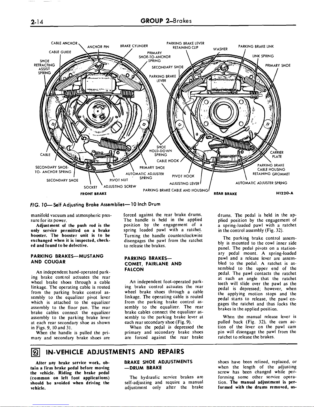
2-1
4
GROUP
2-Bra
kes
FIG.
10-Self
Adiusting Brake Assemblies-
10
Inch Drum
manifold vacuum and atmospheric pres-
forced against the rear brake drums.
drums. The pedal is held in the ap-
sure for its power. The handle is held in the applied plied position by the engagement of
Adjllstment of the push rod is the
position by the engagement of a a spring-loaded pawl with a ratchet
only service permitted on a brake
spring loaded pawl with a ratche!. in the control assembly (Fig.
32).
booster. The booster unit is to be
Turning the handle counterclockwise
The. parking brake control assem-
exchanged when it is inspected, check-
disengages the pawl from the ratchet
bly
is
mounted
to
the
cowl
inner
side
ed and found to be defective.
to release the brakes.
panel. The
cedal ~ivots on a station-
PARKING BRAKES-MUSTANG
AND COUGAR
PARKING
BRAKES-
COMET, FAIRLANE AND
An independent hand-operated parking brake control actuates the rear
wheel brake shoes through a cable
linkage. The operating cable is routed
from the parking brake control assembly to the equalizer pivot lever
which is attached to the equalizer
assembly to the floor pan. The rear
brake cables connect the equalizer
assembly to the parking brake lever
at each rear secondary shoe as shown
in Figs.
9,
10
and
3
1.
When the handle is pulled the primary and secondary brake shoes are
FALCON
An independent foot-operated parking brake control actuates the rear
wheel brake shoes through a cable
linkage. The operating cable is routed
from the parking brake control assembly to the equalizer. The rear
brake cables connect the equalizer assembly to the parking brake lever at
each rear secondary shoe (Fig.
9).
.
When the pedal is depressed the
primary and secondary brake shoes
are forced against the rear brake
ary pedal 'mouni. A spring-loaded
pawl and a release lever are assembled to the pedal. A ratchet is assembled to the upper end of the
pedal. The pawl contacts the ratchet
at such an angle that the ratchet
teeth will slide over the pawl as the
pedal is depressed; however, when
the applying motion stops and the
pedal starts to release, the pawl engages the ratchet and thus locks the
brakes in the applied position.
When the manual release lever is
pulled back (Fig.
32),
the cam action of the lever on the pawl cam
pin will disengage the pawl from the
ratchet to release the brakes.
IN-VEHICLE ADJUSTMENTS AND REPAIRS
Alter any brake service work, ob-
BRAKE SHOE ADJUSTMENTS
tain a firm brake pedal before moving
-DRUM BRAKE
the vehicle. Riding the brake pedal
(common on left foot applications)
The hydraulic service brakes are
should
be avoided when driving the
self-adjusting and require a manual
vehicle.
adjustment only after the brake
shoes have been relined, replaced, or
when the length of the adjusting
screw has been changed while per-
forming some other service operation.
The manual adjustment is per-
formed with the drums removed,
us-
Page 23
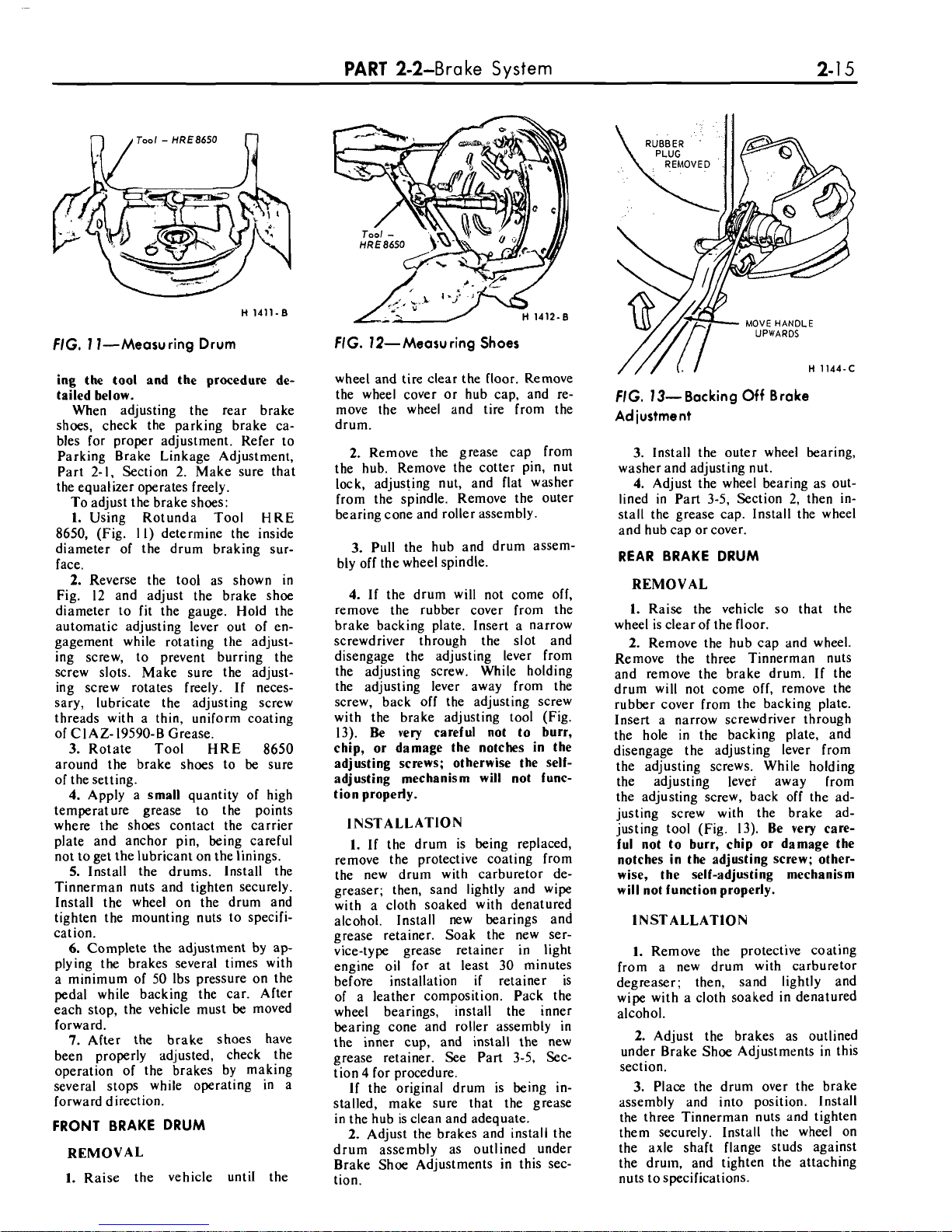
Tool
-
HRE8650
FIG. 1 ]-Measuring Drum
ing the tool and the procedure detailed below.
When adjusting the rear brake
shoes, check the parking brake cables for proper adjustment. Refer to
Parking Brake Linkage Adjustment,
Part 2-1, Section 2. Make sure that
the equalizer operates freely.
To adjust the brake shoes:
1. Using Rotunda Tool
HRE
8650,
(Fig.
I
I)
determine the inside
diameter of the drum braking surface.
2.
Reverse the tool as shown
in
Fig. 12 and adjust the brake shoe
diameter to fit the gauge. Hold the
automatic adjusting lever out of engagement while rotating
the adjusting screw, to prevent burring the
screw slots. Make sure the adjusting screw rotates freely. If neces-
sary, lubricate the adjusting screw
threads with a thin, uniform coating
of CIAZ- 19590-B Grease.
3.Rotate Tool HRE
8650
around the brake shoes to be sure
of the setting.
4.
Apply a small quantity of high
temperature grease to the points
where the shoes contact the carrier
plate and anchor pin, being careful
not to get the lubricant on the linings.
5.
Install the drums. Install the
Tinnerman nuts and tighten securely.
Install the wheel on the drum and
tighten the mounting nuts to specification.
6.
Complete the adjustment by apply ing the brakes several times with
a minimum of 50 Ibs pressure on the
pedal while backing the car. After
each stop, the vehicle must be moved
forward.
7.
After the brake shoes have
been properly adjusted, check the
operation of the brakes by making
several stops while operating in a
forward direction.
FRONT BRAKE DRUM
REMOVAL
1.
Raise the vehicle untiI the
PART
2-2-Bra
ke
System
FIG. 12-Measu ring Shoes
wheel and tire clear the floor. Remove
the wheel cover or hub cap, and remove the wheel and tire from the
drum.
2.
Remove the grease cap from
the hub. Remove the cotter pin, nut
lock, adjusting nut, and flat washer
from the spindle. Remove the outer
bearing cone and roller assembly.
3. Pull the hub and drum assem-
bly off the wheel spindle.
4.
If the drum will not come off,
remove the rubber cover from the
brake backing plate. Insert a narrow
screwdriver through the slot and
disengage the adjusting lever from
the adjusting screw. While holding
the adjusting lever away from the
screw, back off the adjusting screw
with the brake adjusting tool (Fig.
13).
Be
very careful not to burr,
chip, or damage the notches in the
adjusting screws; otherwise the selfadjusting mechanism will not function properly.
INSTALLATION
I.
If the drum is being replaced,
remove the protective coating from
the new drum with carburetor
de-
greaser; then, sand lightly and wipe
with a cloth soaked with denatured
alcohol. Install new bearings and
grease retainer. Soak the new service-type grease retainer in light
engine oil for at least 30 minutes
before installation
if
retainer is
of a leather composition. Pack the
wheel bearings, install the inner
bearing cone and roller assembly in
the inner cup, and install the new
grease retainer. See Part 3-5, Section
4
for procedure.
If the original drum is being in-
stalled, make sure that the grease
in the hub is clean and adequate.
2.
Adjust the brakes and install the
drum assembly as outlined under
Brake Shoe Adjustments in this section.
FIG. 13- Backing
Off
Brake
Adiustment
3. Install the outer wheel bearing,
washer and adjusting nut.
4.
Adjust the wheel bearing as out-
lined in Part 3-5, Section 2, then install the grease cap. Install the wheel
and hub cap or cover.
REAR BRAKE DRUM
REMOVAL
1. Raise the vehicle so that the
wheel is clear of the floor.
2.
Remove the hub cap and wheel.
Remove the three Tinnerman nuts
and remove the brake drum. If the
drum will not come off, remove the
rubber cover from the backing plate.
Insert a narrow screwdriver through
the hole in the backing plate, and
disengage the adjusting lever from
the adjusting screws. While holding
the adjusting lever away from
the adjusting screw, back off the adjusting screw with the brake adjusting tool (Fig. 13). Be very care-
ful not to burr, chip or damage the
notches in the adjusting screw; otherwise, the self-adjusting mechanism
will not function properly.
INSTALLATION
1.
Remove the protective coating
from a new drum with carburetor
degreaser; then, sand lightly and
wipe with a cloth soaked in denatured
alcohol.
2.
Adjust the brakes as outlined
under Brake Shoe Adjustments in this
section.
3. Place the drum over the brake
assembly and into position. Install
the three Tinnerman nuts and tighten
them securely. Install
the wheel on
the axle shaft flange studs against
the drum, and tighten the attaching
nuts to specifications.
Page 24
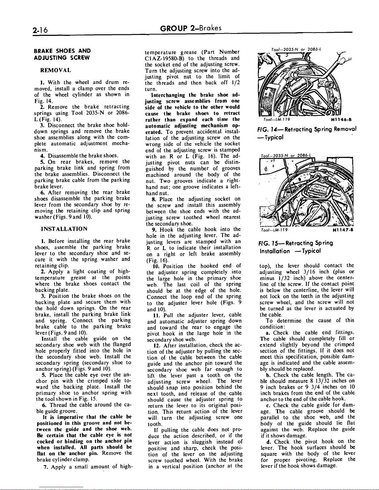
GROUP
2-Bra
kes
BRAKE SHOES AND
ADJUSTING
SCREW
REMOVAL
1.
With the wheel and drum removed, install a clamp over the ends
of the wheel cylinder as shown in
Fig. 14.
2.
Remove the brake retracting
springs
+sing Tool 2035-N or 2086-
L
(Fig. 14).
3.
Disconnect the brake shoe hold-
down springs and remove the brake
shoe assemblies along with the complete automatic adjustment mechanism.
4.
Disassemble the brake shoes.
5.
On rear brakes, remove the
parking brake link and spring from
the brake assemblies. Disconnect the
parking brake cable from the parking
brake lever.
6.
After removing the rear brake
shoes disassemble the parking brake
lever from the secondary shoe by re-
moving the retaining clip and spring
washer (Figs.
9
and 10).
INSTALLATION
1.
Before installing the rear brake
shoes, assemble the parking brake
lever to the secondary shoe and se-
cure it with the spring washer and
retaining clip.
2.
Apply a light coating of hightemperature grease at the points
where the brake shoes contact the
backing plate.
3.
Position the brake shoes on the
backing plate and secure them with
the hold down springs. On the rear
brake, install the parking brake link
and spring. Connect the parking
brake cable to the parking brake
lever (Figs.
9
and 10).
Install the cable guide on the
secondary shoe web with the flanged
hole properly fitted into the hole in
the secondary shoe web. Install the
secondary spring (secondary shoe to
anchor spring) (Figs.
9
and 10).
5.
Place the cable eye over the anchor pin with the crimped side toward the backing plate.
lnstall the
primary shoe to anchor spring with
the tool shown in Fig. 15.
6.
Thread the cable around the ca-
ble guide groove.
It is imperative that the cable be
positioned in this groove and not between the guide and the shoe web.
Be
certain that the cable eye is not
cocked or binding on the anchor pin
when installed. All parts should be
flat on the anchor pin.
Remove the
brake cylinder clamp.
7.
Apply a small amount of high-
temperature grease (Part Number
CIAZ-19580-B) to the threads and
the socket end of the adjusting screw.
Turn the adjusting screw into the adjusting pivot nut to the limit of
the threads and then back off
112
turn.
Interchanging the brake shoe adjusting screw assemblies from one
side of the vehicle to the other would
cause the brake shoes to retract
rather than expand each time the
automatic adjusting mechanism op-
erated.
To prevent accidental installation of the adjusting screw on the
wrong side of the vehicle the socket
end of the adjusting screw is stamped
with an R or
L
(Fig. 16). The ad-
justing pivot nuts can be distin-
guished by the number of grooves
machined around the body of the
nut. Two grooves indicate a righthand nut; one groove indicates a left-
hand nut.
8.
Place the adjusting socket on
the screw and install this assembly
between the shoe ends with the
ad-
jpsting
screw toothed wheel nearest
the secondary shoe.
9.
Hook the cable hook into the
hole in the adjusting lever. The ad-
justing levers are stamped with an
R
or L to indicate their installation
on a right or left brake assembly
(Fig.
16):
10.
Position the hooked end of
the adjuster spring completely into
the large hole in the primary shoe
web. The last coil of the spring
should be at the edge of the hole.
Connect the loop end of the spring
to the adjuster lever hole (Figs.
9
and 10).
11.
Pull the adjuster lever, cable
and automatic adjuster spring down
and toward the rear to engage the
pivot hook in the large hole in the
secondary shoe web.
12.
After installation, check the action of the adjuster by pulling the section of the cable between the cable
guide and the anchor pin toward the
secondary shoe web far enough to
lift the lever past a tooth on the
adjusting screw wheel. The lever
should snap into position behind the
next tooth, and release of the cable
should cause the adjuster spring to
return the lever to its original position. This return action of the lever
will turn the adjusting screw one
tooth.
If
pulling the cable does not pro-
duce the action described, or
if
the
lever action is sluggish instead of
positive and sharp, check the position of the lever on the adjusting
screw toothed wheel. With the brake
in a vertical position (anchor at the
FIG.
14-Retracting Spring Removal
-Typical
NG.
15- Retracting Spring
Installation -Typical
top), the lever should contact the
adjusting wheel 3/16 inch (plus
or
minus 1/32 inch) above the center-
line of the screw. If the contact point
is below the centerline, the lever will
not lock on the teeth in the adjusting
screw wheel, and the screw will not
be turned as the lever is actuated by
the cable.
To determine the cause of this
condition:
a.
Check the cable end fittings,
The cable should completely fill or
extend slightly beyond the crimped
section of the fittings.
If
it does not
meet this specification, possible damage is indicated and the cable assembly should
be
replaced.
b.
Check the cable length. The ca-
ble should measure 8 13/32 inches on
9
inch brakes or 9 314 inches on 10
inch brakes from the end of the cable
anchor to the end of the cable hook.
c.
Check the cable guide for dam-
age. The cable groove should
be
parallel to the shoe web, and the
body of the guide should lie flat
against the web. Replace the guide
if
it shows damage.
d.
Check the pivot hook on the
lever. The hook surfaces should
be
square with the body of the lever
for proper pivoting. Replace the
lever
if
the hook shows damage.
Page 25
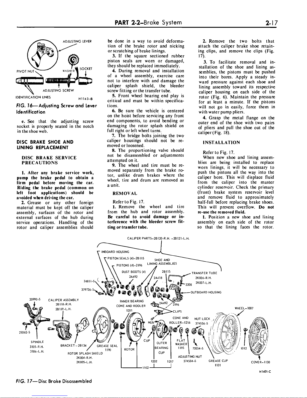
PART
2-2-Bra
ke
System-
2-1
7
be
done in a way to avoid deiorma-
tion
of the brake rotor and nicking
or scratching of brake linings.
3.
If the square sectioned rubber
piston seals are worn or damaged,
they should be replaced immediately.
4.
During removal and installation
ADJUSTING
SCREW
IDENTIFICATION LINES
H1143-0
FIG.
16-Adjusting Screw and Lever
Identification
e.
See that the adjusting screw
socket is properly seated in the notch
in the shoe web.
DISC BRAKE SHOE AND
LINING REPLACEMENT
DISC BRAKE SERVICE
PRECAUTIONS
1.
After any brake service work,
pump the brake pedal to obtain a
firm pedal before moving the car.
Riding the brake
pedal (common on
left foot applications) should be
avoided when driving the car.
2.
Grease or any other foreign
material must be kept off the caliper
assembly, surfaces of the rotor and
external surfaces of the hub during
service operations. Handling of the
rotor and caliper assemblies should
of a
wheei assembly, exercise care
not to interfere with and damage the
caliper splash shield, the bleeder
screw fitting or the transfer tube.
5.
Front wheel bearing end play is
critical and must be within specifications.
6.
Be sure the vehicle is centered
on the hoist before servicing any front
end components, to avoid bending or
damaging the rotor splash shield on
full right or left wheel turns.
7.
The bridge bolts joining the twocaliper housings should not be removed or loosened.
8.
The proportioning valve should
not be disassembled or adjustments
attempted on it.
9.
The wheel and tire must be re-
moved separately from the brake rotor, unlike drum brakes where the
wheel, tire and drum are removed as
a unit.
REMOVAL
Refer to Fig. 17.
1.
Remove the wheel and tire
from the hub and rotor assembly.
Be
careful to avoid damage or interference with the bleeder screw fitting ortransfer tube.
2.
Remove the two bolts that
attach the caliper brake shoe retaining clips, and remove the clips (Fig.
17).
3.
To facilitate removal and installation of the shoe and lining assemblies, the pistons must be pushed
into their bores. Apply a steady inward pressure against each shoe and
lining assembly toward its respective
caliper housing on each side of the
rotor (Fig.
6).
Maintain the pressure
for at least a minute. If the pistons
will not go in easily, force them in
with water pump pliers.
4.
Grasp the metal flange on the
outer end of the shoe with two pairs
of pliers and pull the shoe out of the
caliper (Fig.
18).
INSTALLATION
Refer to Fig. 17.
When new shoe and lining assem-
blies are being installed to replace
worn linings, it will be necessary to
push the pistons all the way into the
caliper bore. This will displace fluid
from the caliper into the master
cylinder reservoir. Check the primary
(front) brake system reservoir level
and remove fluid to approximately
half-full before replacing brake shoes.
This will prevent overflow.
Do not
re-use the removed fluid.
1.
Position a new shoe and lining
assembly on each side of the rotor
so that the lining faces the rotor.
CALIPER PARTS-2BI2O-R.H. -2BI2I-L.H.
TRANSFERTUBE
UTBOARD HOUSING
20990-5
CALIPER
ASSEMBLY
WHEEL-1007
2
1
3105-R.H.
3lOh.L.H.
H1401-C
FIG.
17-Disc Brake Disassembled
Page 26

 Loading...