

Page 1

Feel the difference
FordGalaxy
FordS-MAX
Owner's handbook
Page 2

The information contained in this publication was correct at the time of going to print. In the
interest of development the right is reserved to change specifications, design or equipment
at any time without notice and without incurring any obligations. This publication, or part
thereof, may not be reproduced nor translated without our approval. Errors and omissions
excepted.
© Ford Motor Company 2007
All rights reserved.
Part number: 7M2J-19A321-DA (CG3533en) 01/2007 20070129120050
Page 3

Introduction
About this handbook........................7
Symbols glossary..............................7
Parts and accessories......................7
Quick start
Quick start..........................................8
Child safety
Child seats........................................19
Booster cushions............................20
Child seat positioning......................21
ISOFIX anchor points......................23
Child safety locks............................24
Occupant protection
Principle of operation.....................25
Fastening the seat belts................28
Seat belt height adjustment...........31
Seat belt reminder..........................32
Using seat belts during
pregnancy....................................32
Disabling the passenger
airbag............................................32
Keys and remote
controls
Using the key...................................34
General information on radio
frequencies..................................34
Programming the remote
control...........................................34
Changing the remote control
battery...........................................34
Locks
Locking and unlocking...................36
Global opening and closing...........39
Keyless entry...................................39
Engine immobiliser
Principle of operation.....................44
Coded keys.....................................44
Arming the engine immobiliser.....44
Disarming the engine
immobiliser...................................44
Alarm
Principle of operation.....................45
Arming the alarm.............................47
Disarming the alarm........................47
Steering wheel
Adjusting the steering wheel.........49
Audio control...................................49
Wipers and washers
Windscreen wipers..........................51
Autowipers........................................51
Rain sensor......................................52
Windscreen washers.....................52
Rear window wiper and
washers........................................52
Headlamp washers........................53
Checking the wiper blades...........53
Changing the wiper blades...........54
Technical specifications.................55
Lighting
Lighting control................................56
1
Table of contents
Page 4

Autolamps........................................57
Front fog lamps...............................57
Rear fog lamps................................57
Headlamp levelling..........................58
Hazard warning flashers................59
Adaptive front lighting system
(AFS)..............................................59
Direction indicators..........................61
Interior lamps....................................61
Removing a headlamp...................62
Changing a bulb..............................63
Bulb specification chart..................75
Windows and mirrors
Electric windows.............................76
Exterior mirrors................................79
Electric exterior mirrors..................79
Interior mirror....................................81
Auto-dimming mirror.......................81
Rear quarter windows...................82
Instruments
Gauges.............................................83
Warning lamps and indicators......84
Audible warnings and
indicators.......................................87
Information displays
General information........................88
Trip computer..................................97
Personalised settings.....................99
Information messages.................102
Climate control
Principle of operation.....................113
Air vents...........................................113
Manual climate control..................114
Automatic climate control.............117
Heated windows and mirrors......121
Auxiliary heater...............................122
Seats
Sitting in the correct position.......127
Manual seats..................................127
Electric seats..................................128
Head restraints..............................130
Rear seats.......................................131
Heated seats.................................135
Ventilated seats.............................136
Front seat armrest.........................137
Convenience features
Sun visors.......................................138
Sun blinds.......................................138
Instrument lighting dimmer..........139
Clock...............................................139
Cigar lighter....................................139
Ashtray............................................140
Auxiliary power sockets...............140
Cup holders....................................140
Glove box........................................141
Centre console...............................141
Storage compartments...............142
Map pockets..................................144
Seat back trays..............................144
Glasses holder...............................144
Memory function...........................144
Childminder mirror.........................146
Auxiliary input (AUX IN) socket.....146
2
Table of contents
Page 5

Starting the engine
General information.......................147
Ignition switch.................................147
Keyless starting..............................147
Steering wheel lock.......................149
Starting a petrol engine................150
Starting a diesel engine.................151
Diesel particulate filter (DPF)........151
Switching off the engine...............152
Fuel and refuelling
Safety precautions........................153
Fuel quality - Petrol........................153
Fuel quality - Diesel.......................153
Catalytic converter........................153
Fuel filler flap...................................154
Refuelling........................................154
Fuel consumption.........................154
Technical specifications................154
Transmission
Manual transmission.....................156
Automatic transmission................157
Brakes
Principle of operation....................160
Hints on driving with ABS.............160
Parking brake..................................161
Electric parking brake (EPB).........161
Stability control
Principle of operation....................166
Using stability control....................167
Hill launch assist
(HLA)
Principle of operation....................168
Using HLA.......................................168
Active suspension
Principle of operation.....................171
Using active suspension...............171
Parking aid
Principle of operation....................173
Using the parking aid....................173
Cruise control
Principle of operation....................175
Using cruise control.......................175
Adaptive cruise control
(ACC)
Principle of operation....................177
Using ACC......................................179
Forward alert function...................181
Load carrying
General information......................184
Luggage anchor points................185
Sliding loadspace floor..................187
Rear under floor storage..............188
Cargo nets......................................189
Luggage covers............................192
Roof racks and load carriers.......193
Load retaining fixtures..................193
Dog guard.......................................197
3
Table of contents
Page 6

Towing
Towing a trailer..............................200
Detachable tow ball.....................200
Retractable tow ball.....................203
Driving hints
Running-in......................................208
Emergency
equipment
First aid kit......................................209
Warning triangle............................209
Status after a
collision
Inspecting safety system
components...............................210
Fuses
Fuse box locations.........................211
Changing a fuse............................212
Fuse specification chart...............213
Vehicle recovery
Towing points................................222
Towing the vehicle on four
wheels........................................223
Maintenance
General information.....................224
Opening and closing the
bonnet........................................225
Engine compartment overview -
2.0L Duratec-HE (MI4).............226
Engine compartment overview -
2.3L Duratec-HE (MI4).............227
Engine compartment overview -
2.5L Duratec-ST (VI5)..............228
Engine compartment overview -
1.8L Duratorq-TDCi (Kent)
Diesel..........................................229
Engine compartment overview -
2.0L Duratorq-TDCi (DW)
Diesel..........................................230
Engine oil check.............................231
Engine coolant check..................232
Automatic transmission fluid
check..........................................233
Brake and clutch fluid check......233
Power steering fluid check.........234
Washer fluid check.......................234
Technical specifications...............235
Vehicle care
Cleaning the exterior....................237
Cleaning the interior.....................238
Repairing minor paint damage....238
Vehicle battery
Battery care...................................239
Using booster cables...................239
Wheels and tyres
General information......................241
Changing a road wheel................241
Tyre repair kit.................................243
Run flat tyres.................................250
Tyre care.........................................251
Using winter tyres.........................252
Using snow chains.......................252
Tyre pressure monitoring
system........................................252
4
Table of contents
Page 7

Technical specifications...............253
Vehicle identification
Vehicle identification plate...........256
Vehicle identification number
(VIN).............................................256
Engine number - 2.0L Duratec-HE
(MI4)............................................256
Engine number - 2.3L Duratec-HE
(MI4)............................................256
Engine number - 2.5L Duratec-ST
(VI5).............................................256
Engine number - 1.8L
Duratorq-TDCi (Kent) Diesel....256
Engine number - 2.0L
Duratorq-TDCi (DW) Diesel.....256
Technical specific-
ations
Technical specifications...............257
Telephone
General information.....................265
Telephone setup...........................265
Bluetooth setup............................267
Telephone controls......................268
Using the telephone - Vehicles
Without: Navigation System.....269
Using the telephone - Travel Pilot
EX.................................................272
Voice control
Principle of operation...................275
Using voice control.......................276
Audio unit commands..................276
Telephone commands.................281
Navigation system
commands.................................286
Climate control commands........286
Appendices
Type approvals..............................289
Type approvals..............................295
5
Table of contents
Page 8

6
Page 9
ABOUT THIS HANDBOOK
Thank you for choosing Ford. We
recommend that you take some time
to get to know your vehicle by
reading this handbook. The more that
you know about it, the greater the
safety and pleasure you will get from
driving it.
Note:
This handbook describes
every model and option, sometimes
even before they are generally
available. It may describe options not
fitted to your vehicle.
Note:
Always use and operate your
vehicle in line with all applicable laws
and regulations.
Note:
Pass on this handbook when
selling your vehicle. It is an integral
part of the vehicle.
SYMBOLS GLOSSARY
Symbols in this handbook
WARNING
You risk death or serious injury
to yourself and others if you do
not follow the instructions highlighted
by the warning symbol.
CAUTION
You risk damaging your vehicle
if you do not follow the
instructions highlighted by the caution
symbol.
Symbols on your vehicle
When you see these symbols, read
and follow the relevant instructions
in this handbook before touching or
attempting adjustment of any kind.
PARTS AND ACCESSORIES
Genuine Ford parts and accessories
have been designed specifically for
your vehicle. Unless we have
specifically stated, we have not
tested non-Ford parts and
accessories and, therefore, we will
not guarantee that they are suitable
for your vehicle. We recommend that
you ask your Ford Dealer for advice
on parts and accessories suitable for
your vehicle.
7
Introduction
Page 10
QUICK START
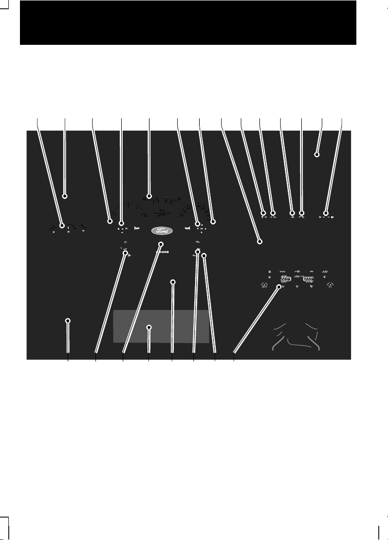
Instrument panel overview - LHD
A
V U RS Q P OT
B EC F G IH J K L M ND
E74123
Lighting controls. See Lighting (page 56).
A
Air vents. See Climate control (page 113).
B
Direction indicators. See Lighting (page 56). Voice control and
phone buttons. See separate handbook.
C
Audio controls. See Steering wheel (page 49).
D
8
Quick start
Page 11

Instrument cluster. See Instruments (page 83).
E
Information display controls. See Information displays (page 88).
F
Wiper lever. See Wipers and washers (page 51).
G
Audio or navigation unit. See separate handbook.H
Stability control switch. See Stability control (page 166).
I
Parking aid switch. See Parking aid (page 173).
J
Hazard warning flasher switch. See Lighting (page 56).
K
Passenger airbag deactivation warning lamp. See Occupant
protection (page 25).
L
Storage compartment. See Convenience features (page 138).
M
Heated windscreen and heated rear window switches. See Climate
control (page 113).
N
Climate controls. See Climate control (page 113).
O
Ignition switch. See Starting the engine (page 147).
P
Cruise control switches. See Cruise control (page 175). Adaptive
cruise control switches. See Adaptive cruise control (ACC)
(page 177).
Q
Steering wheel adjustment lever. See Steering wheel (page 49).
R
Driver Knee airbag. See Occupant protection (page 25).
S
Horn.T
Cruise control switches. See Cruise control (page 175). Adaptive
cruise control switches. See Adaptive cruise control (ACC)
(page 177).
U
Storage compartment. See Convenience features (page 138).
V
9
Quick start
Page 12
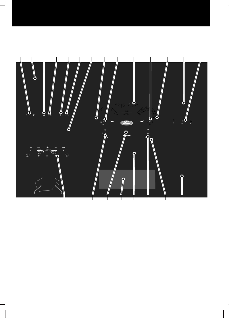
Instrument panel overview - RHD
OPQRSUV T
DCBA
E75798
NMJ LIHF GE K
Heated windscreen and heated rear window switches. See Climate
control (page 113).
a
Storage compartment. See Convenience features (page 138).
b
Hazard warning flasher switch. See Lighting (page 56).
c
Passenger airbag deactivation warning lamp. See Occupant
protection (page 25).
d
Stability control switch. See Stability control (page 166).
e
10
Quick start
Page 13

Parking aid switch. See Parking aid (page 173).
f
Audio or navigation unit. See separate handbook.g
Direction indicators. See Lighting (page 56). Voice control and
phone buttons. See separate handbook.
h
Audio controls. See Steering wheel (page 49).
I
Instrument cluster. See Instruments (page 83).
j
Information display controls. See Information displays (page 88).
k
Wiper lever. See Wipers and washers (page 51).
l
Air vents. See Climate control (page 113).
m
Lighting controls. See Lighting (page 56).
n
Storage compartment. See Convenience features (page 138).
o
Ignition switch. See Starting the engine (page 147).
p
Cruise control switches. See Cruise control (page 175). Adaptive
cruise control switches. See Adaptive cruise control (ACC)
(page 177).
q
Steering wheel adjustment lever. See Steering wheel (page 49).
r
Driver Knee airbag. See Occupant protection (page 25).
s
Horn.t
Cruise control switches. See Cruise control (page 175). Adaptive
cruise control switches. See Adaptive cruise control (ACC)
(page 177).
u
Climate controls. See Climate control (page 113).
v
11
Quick start
Page 14
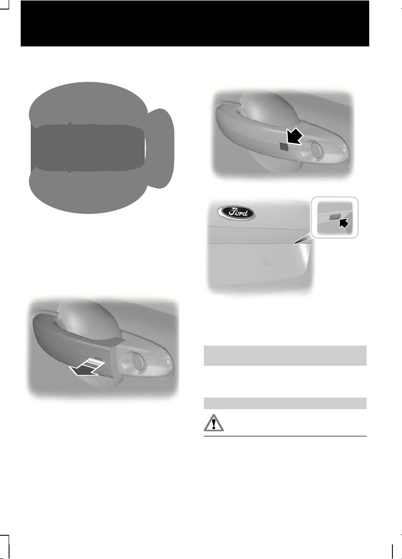
Keyless entry
E78276
Passive locking and unlocking
requires a valid passive key to be
located within one of the three
external detection ranges.
Unlocking the vehicle
E78278
Pull a door handle to unlock all the
doors and the luggage compartment
lid and disarm the alarm.
Locking the vehicle
E87384
E87435
Locking buttons are located on each
of the front doors and the luggage
compartment lid.
See Keyless entry (page 39).
Adjusting the steering
wheel
WARNING
Never adjust the steering wheel
when the vehicle is moving.
12
Quick start
Page 15
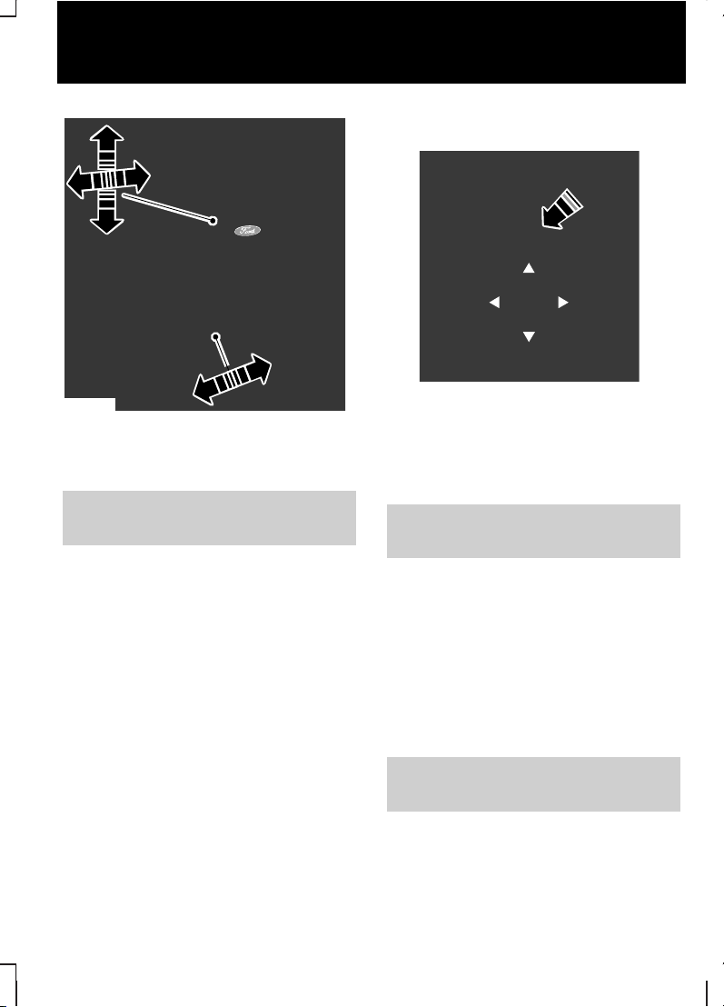
E71221
Release the locking lever to adjust
the height of the steering wheel and
its distance from the driver.
See Adjusting the steering
wheel (page 49).
Electric folding mirrors
E72623
Press the button to fold or unfold the
mirrors.
See Electric exterior mirrors
(page 79).
Reverse mirror dipping
Depending on the selected mirror
position, the relevant exterior mirror
will dip whenever you select reverse
gear, giving you a view of the kerb.
When you first use this feature, the
mirrors will dip to a preset position.
You can programme the degree of
dipping.
See Electric exterior mirrors
(page 79).
13
Quick start
Page 16
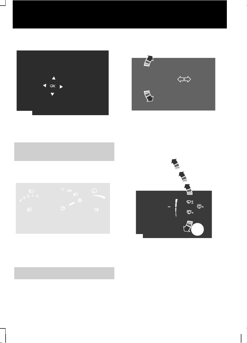
Information displays
E70499
Use the arrow buttons to navigate
through the menus and press OK to
make a selection.
See Information displays (page
88).
Autolamps
E70719
The headlamps will come on and go
off automatically depending on the
ambient light.
See Lighting control (page 56).
Direction indicators
E70727
Note:
Tap the lever up or down to
make the direction indicators flash
only three times.
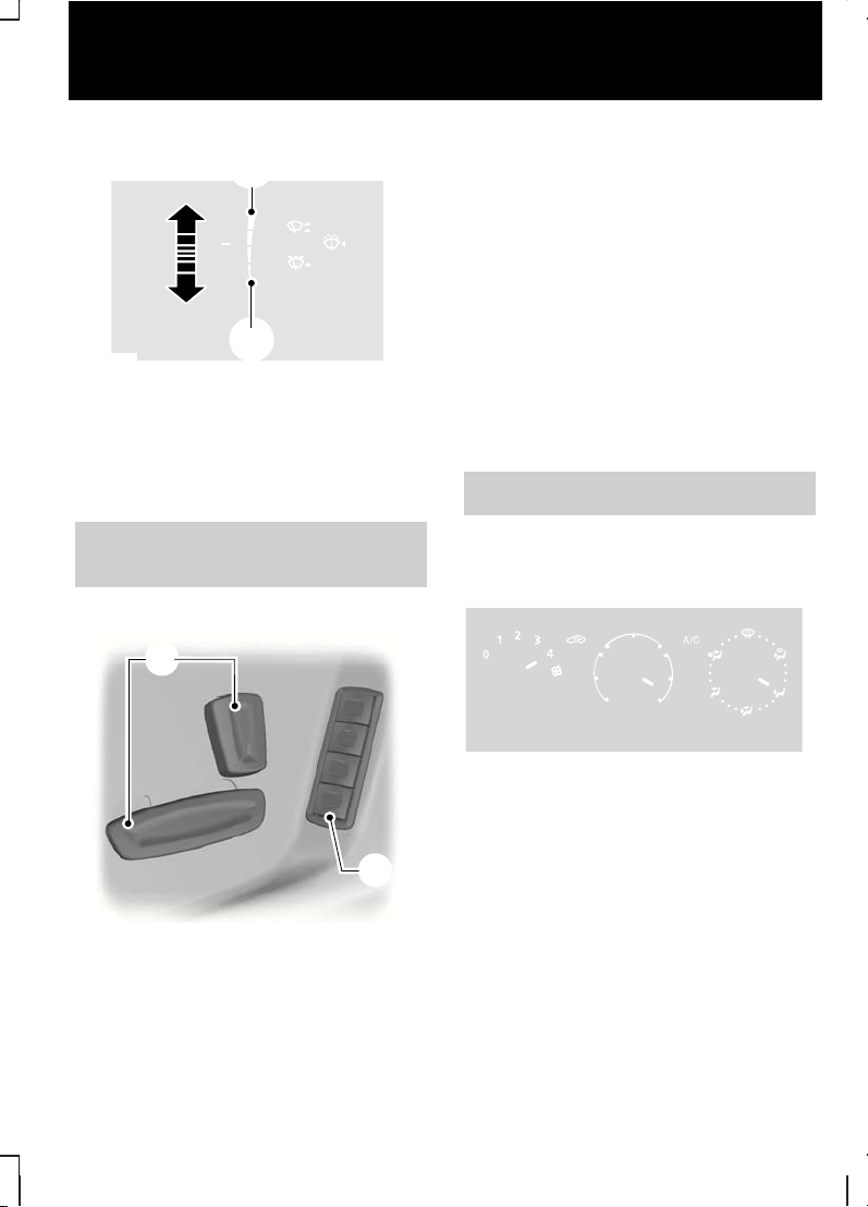
Autowipers
B
C
D
A
E70696
Single wipeA
Autowipers
B
Normal wipeC
High speed wipeD
14
Quick start
Page 17
E70316
A
B
High sensitivityA
Low sensitivityB
Adjust the sensitivity of the rain
sensor using the rotary control.
See Windscreen wipers (page
51).
Memory function
A
B
E86768
Seat adjustment controls.A
Memory pre-set buttons.B
1. Vehicles without keyless starting,
insert the ignition key and turn it
to position I or II. Vehicles with
keyless starting, press the start
button.
2. Adjust the seat and exterior
mirrors to the desired position.
3. Press and hold for at least 3
seconds the desired pre-set
button B.
4. A message will be displayed in the
message centre to confirm the
action. A single chime will sound
to confirm.
See Memory function (page 144).
Manual climate control
Heating the interior quickly
E71377
15
Quick start
Page 18
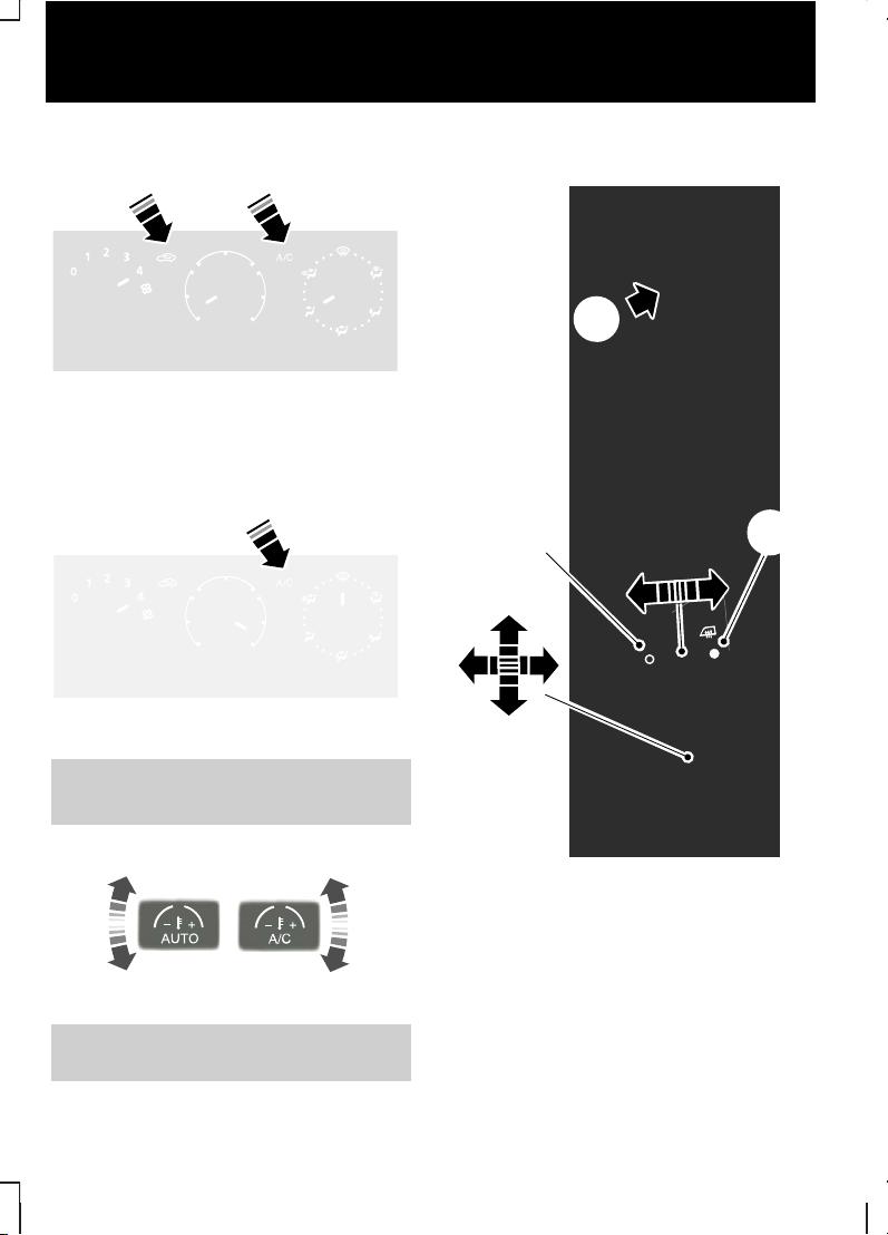
Cooling the interior quickly
E71381
Defrosting and demisting the
windscreen
E71382
See Manual climate control
(page 114).
Automatic climate control
E70304
See Automatic climate control
(page 117).
Rear seat air vents
E73131
A
B
C
Air flow through lower air
vent
A
Air flow through upper air
vent
B
Upper air ventC
Select position B to defrost or demist
the rear side windows.
16
Quick start
Page 19
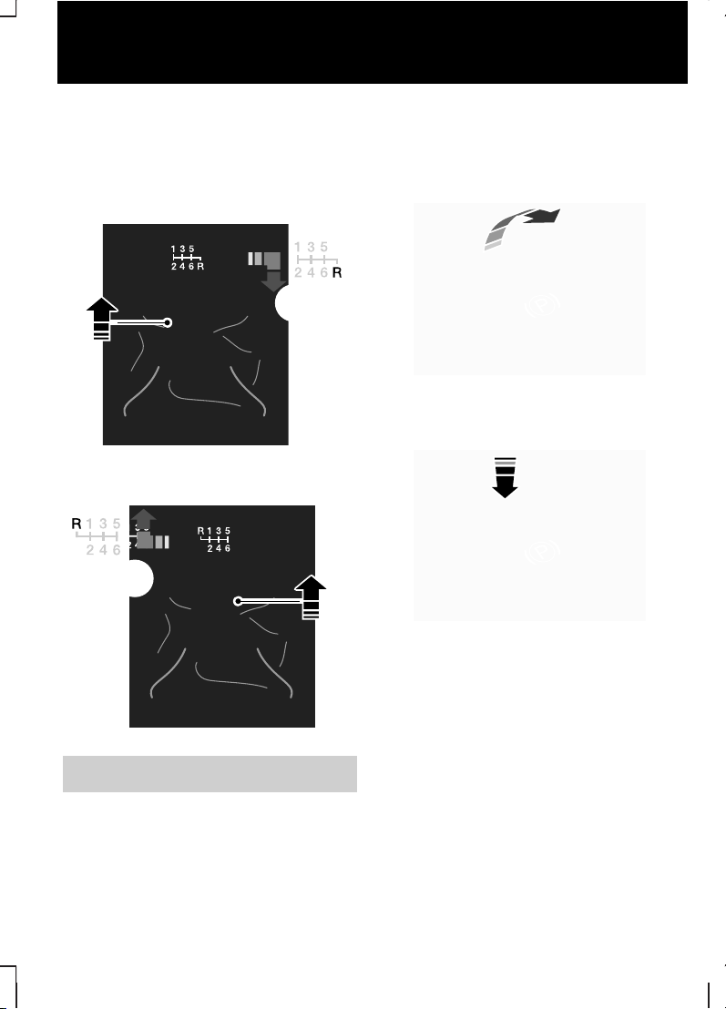
Selecting reverse gear
Vehicles with a 6-speed
transmission
Vehicles with a petrol engine
E75051
1
2
Vehicles with a diesel engine
E75052
2
1
See Transmission (page 156).
Electric parking brake
(EPB)
Applying the EPB
E70528
Releasing the EPB manually
E70529
Hold the brake or clutch pedal
depressed and press down the
switch.
Releasing the EPB
automatically
Engage first or reverse gear, move
off as normal using the accelerator
and clutch pedals and the EPB will
be released automatically.
17
Quick start
Page 20

See Electric parking brake
(EPB) (page 161).
18
Quick start
Page 21
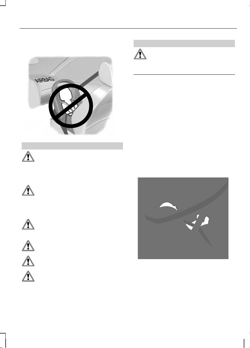
CHILD SEATS
E68916
WARNINGS
Secure children that are less
than 150 centimetres tall or less
than 12 years of age in a suitable,
approved child restraint, in the rear
seat.
Original text according to ECE
R94.01: Extreme Hazard! Do not
use a rearward facing child restraint
on a seat protected by an air bag in
front of it!
Read and follow the
manufacturer’s instructions
when you are fitting a child restraint.
Do not modify child restraints in
any way.
Do not hold a child on your lap
when the vehicle is moving.
Do not leave unattended
children in your vehicle.
WARNINGS
If your vehicle has been involved
in an accident, have the child
restraints checked by properly
trained technicians.
Note:
Mandatory use of child
restraints varies from country to
country.
A choice of ECE approved child
restraints is available from your Ford
Dealer. Ask for the child restraint that
we recommend for your vehicle.
Child restraints for different
mass groups
Use the correct child restraint as
follows:
Baby safety seat
E68918
Secure children that weigh less than
13 kilogrammes in a rearward facing
baby safety seat in the rear seat.
19
Child safety
Page 22
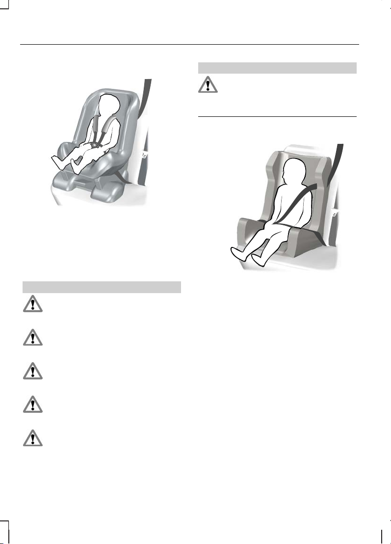
Child safety seat
E68920
Secure children that weigh between
13 and 18 kilogrammes in a child
safety seat in the rear seat.
BOOSTER CUSHIONS
WARNINGS
Do not install a booster seat or
a booster cushion with only the
lap strap of the seat belt.
Do not install a booster seat or
a booster cushion with a seat
belt that is slack or twisted.
Do not put the seat belt under
your child’s arm or behind its
back.
Do not use pillows, books or
towels to boost your child’s
height.
Make sure that your children sit
in an upright position.
WARNINGS
Secure children that weigh more
than 15 kilogrammes but are
less than 150 centimetres tall in a
booster seat or a booster cushion.
Booster seat
E70710
We recommend that you use a
booster seat that combines a
cushion with a backrest. The raised
seating position will allow you to
position the shoulder strap of the
adult seat belt over the centre of your
child’s shoulder and the lap strap
tightly across its hips.
20
Child safety
Page 23
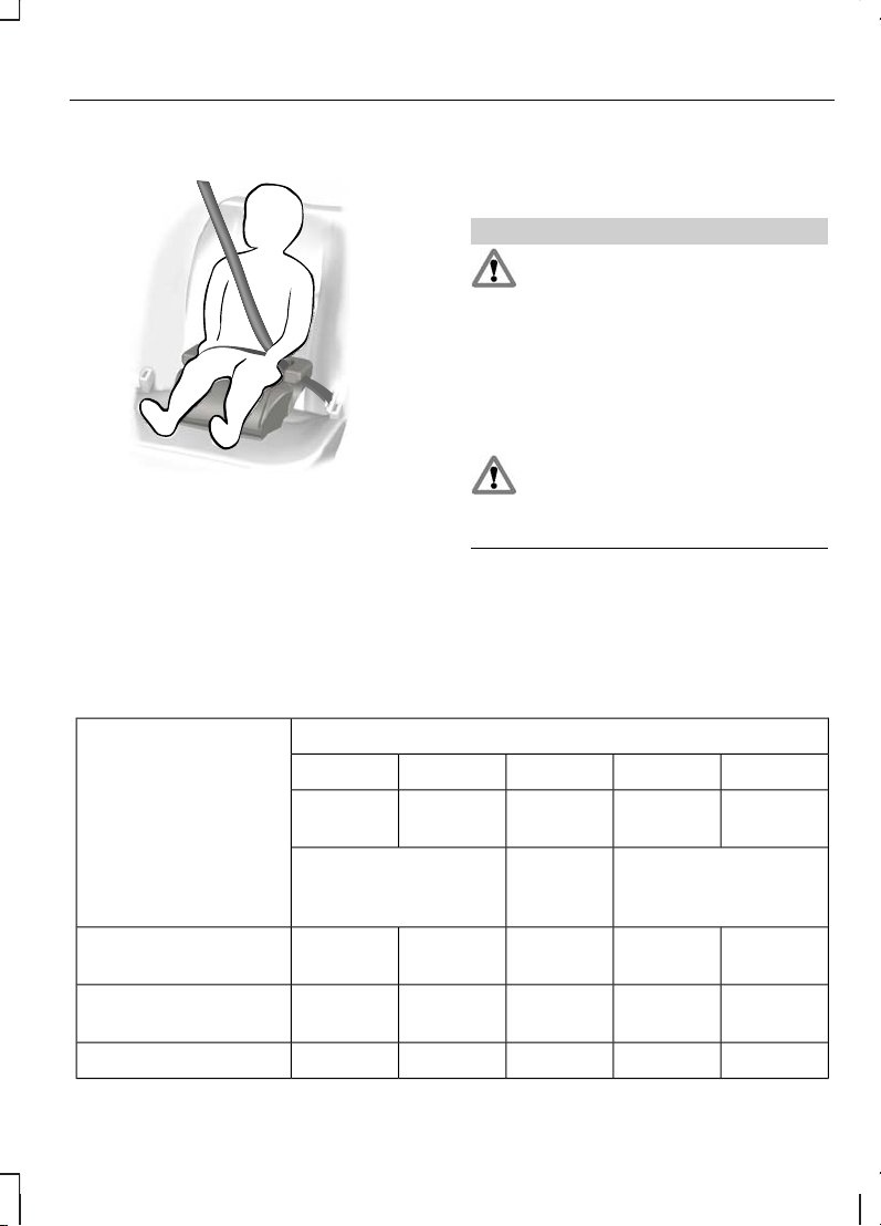
Booster cushion
E68924
CHILD SEAT POSITIONING
WARNINGS
When using a child restraint with
a support leg on a second row
seat, make sure the support leg rests
securely on the lid of the underfloor
storage compartment. Ensure that
the foam spacer inside the storage
compartment is correctly installed
and that the lid is properly positioned
on the storage compartment.
When using a forward facing
child seat on a second or third
row seat, always remove the head
restraint from that seat.
Note:
When using a child seat on a
second row seat, adjust the second
row seat to the most practical
position for the driver.
Child seat positions
Mass group categoriesSeating positions
IIIIII0+0
22 - 36
kg
15 - 25
kg
9 - 18 kgUp to 13
kg
Up to 10
kg
Booster seat or
cushion
Child
safety
seat
Baby safety seat
U¹U¹U¹XXFront passenger
seat with airbag ON
U¹U¹U¹U¹U¹Front passenger
seat with airbag OFF
UUUUUSecond row seats
21
Child safety
Page 24

Mass group categoriesSeating positions
IIIIII0+0
22 - 36
kg
15 - 25
kg
9 - 18 kgUp to 13
kg
Up to 10
kg
Booster seat or
cushion
Child
safety
seat
Baby safety seat
XXIUIUIUSecond row ISOfix
seats
XXA, B, B1,
C, D
C, D, EESecond row ISOfix
classes*
UUUUUThird row Galaxy
UFUFUFL, UFL, UFThird row S-MAX
X Not suitable for children in this mass group.
U Suitable for universal category child restraints approved for use in this mass
group.
IU Suitable for universal category ISOFIX child restraints approved for use in
this mass group.
U¹ Suitable for universal category child restraints approved for use in this mass
group. However, we recommend that you secure children in a government
approved child restraint, in the rear seat.
L Suitable only for the following rearward facing child restraints: Roemer
Baby-Safe (E1-04301146), Roemer Baby-Safe Plus (E1-04301146), Britax Cosy
Tot (E1-04301146), Britax Cosy Tot Premium (E1-04301146), Maxi-Cosi Cabrio
(E4-44R-043517).
UF Suitable for universal category forward facing restraints approved for use
in this mass group.
* As defined by ECE-R16.
22
Child safety
Page 25
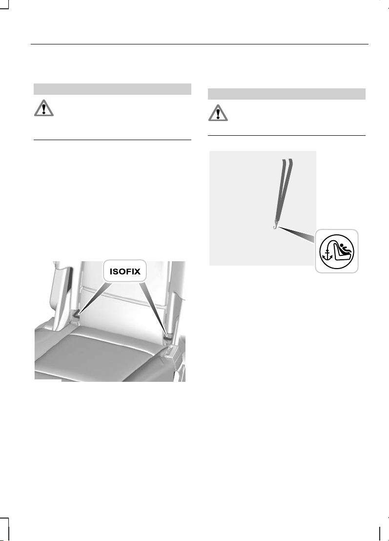
ISOFIX ANCHOR POINTS
WARNING
Use an anti-rotation device
when using the ISOFIX system.
We recommend the use of a top
tether or support leg.
Note:
When you are purchasing an
ISOFIX restraint, make sure that you
know the correct mass group and
ISOFIX size class for the intended
seating locations. See Child seat
positioning (page 21).
Your vehicle is fitted with ISOFIX
anchor points that accommodate
universally approved ISOFIX child
restraints.
E75531
The ISOFIX system comprises of two
rigid attachment arms on the child
restraint that attach to anchor points
on the rear seats, where the cushion
and backrest meet. Tether anchor
points may also be fitted.
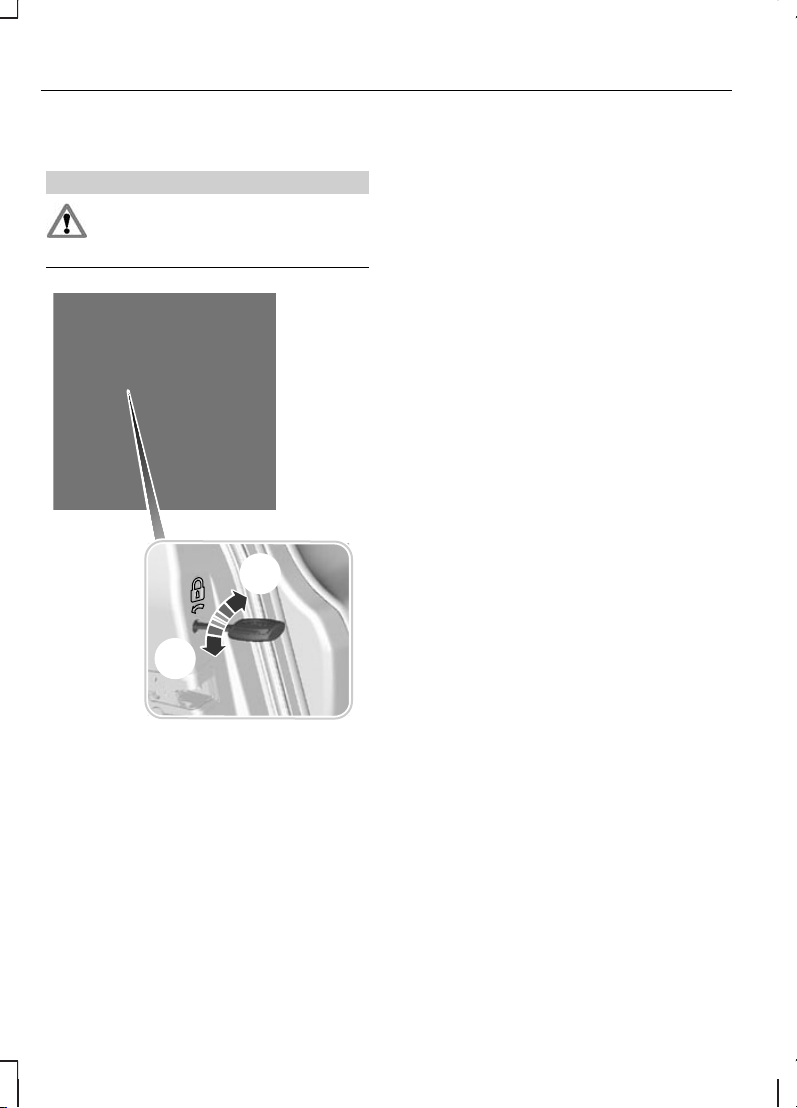
Attaching a child seat with
top tethers
WARNING
Do not attach a tether strap to
anything other than the correct
tether anchor point.
E75532
Route the tether strap to the anchor
point. Tighten the tether strap in line
with the manufacturer's instructions.
23
Child safety
Page 26
CHILD SAFETY LOCKS
WARNING
You cannot open the doors
from inside if you have put the
child safety locks on.
E73697
A
B
LockA
UnlockB
24
Child safety
Page 27
PRINCIPLE OF OPERATION
Airbags
WARNINGS
Do not modify the front of your
vehicle in any way. This could
adversely affect deployment of the
airbags.
Original text according to ECE
R94.01: Extreme Hazard! Do not
use a rearward facing child restraint
on a seat protected by an airbag in
front of it!
Wear a seat belt and keep
sufficient distance between
yourself and the steering wheel. Only
when you use the seat belt properly,
can it hold you in a position that
allows the airbag to achieve its
optimum effect. See Sitting in the
correct position (page 127).
Have repairs to the steering
wheel, steering column, seats,
airbags and seat belts carried out by
properly trained technicians.
Keep the areas in front of the
airbags free from obstruction.
Do not affix anything to or over the
airbag covers.
Do not poke sharp objects into
areas where airbags are fitted.
This could damage and adversely
affect deployment of the airbags.
Use seat covers designed for
seats with side airbags. Have
these fitted by properly trained
technicians.
Note:
You will hear a loud bang and
see a cloud of harmless powdery
residue if an airbag deploys. This is
normal.
Note:
Only wipe airbag covers with
a damp cloth.
The restraint system comprises:
•
a driver airbag
•
a front passenger airbag
•
side airbags
•
a driver knee airbag
•
curtain airbags
•
a driver seat belt pretensioner
•
a front passenger seat belt
pretensioner
•
crash sensors
•
an airbag warning lamp
•
a seat belt reminder
•
an electronic control and
diagnostic unit.
You can also have your vehicle fitted
with:
•
an airbag deactivation switch
•
an airbag deactivation warning
lamp.
25
Occupant protection
Page 28
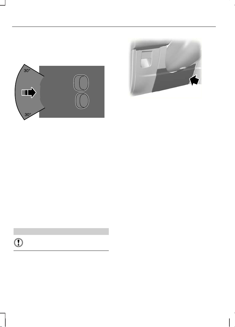
Driver and front passenger
airbags
E74302
The driver and front passenger
airbags will deploy during significant
frontal collisions or collisions that are
up to 30 degrees from the left or the
right. The airbags will inflate within a
few thousandths of a second and
deflate on contact with the
occupants, thus cushioning forward
body movement. During minor frontal
collisions, overturns, rear collisions
and side collisions, the driver and
front passenger airbags will not
deploy.
Driver knee airbag
CAUTION
Do not attempt to open the
driver knee airbag cover.
E86311
The driver knee airbag will deploy
during frontal collisions or collisions
that are up to 30 degrees from the
left or the right. The airbag will inflate
within a few thousandths of a second
and deflate on contact with the
occupants, thus providing a cushion
between the driver’s knees and the
steering column. During overturns,
rear collisions and side collisions, the
knee airbag will not deploy.
Note:
The knee airbag has a lower
deployment threshold than the front
airbags. During a minor collision, it is
possible that only the knee airbag
deploys.
26
Occupant protection
Page 29
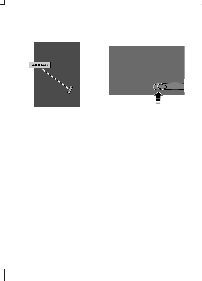
Side airbags
E72658
Side airbags are fitted inside the
seatback of the front seats. A label
indicates that side airbags are fitted
to your vehicle.
The side airbags will deploy during
significant lateral collisions. Only the
airbag on the side affected by the
collision will deploy. The airbags will
inflate within a few thousandths of a
second and deflate on contact with
the occupants, thus providing
protection for the chest and shoulder
areas. During minor lateral collisions,
overturns, front collisions and rear
collisions, the side airbags will not
deploy.
Curtain airbags
E75004
Curtain airbags are fitted inside the
trim panels over the front and rear
side windows. Moulded badges in
the B-pillar trim panels indicate that
curtain airbags are fitted to your
vehicle.
The curtain airbags will deploy during
significant lateral collisions. Only the
airbag on the side affected by the
collision will deploy. The airbag will
inflate within a few thousandths of a
second and deflate on contact with
the occupants, thus providing
protection for the head. During minor
lateral collisions, front collisions, rear
collisions, or overturns the curtain
airbags will not deploy.
27
Occupant protection
Page 30
Seat belts
WARNINGS
Wear a seat belt and keep
sufficient distance between
yourself and the steering wheel. Only
when you use the seat belt properly,
can it hold you in a position to
achieve its optimum effect. See
Sitting in the correct position
(page 127).
Never use a seat belt for more
than one person.
Use the correct buckle for each
seat belt.
Do not use a seat belt that is
slack or twisted.
Do not wear thick clothing. The
seat belt must fit tightly around
your body to achieve its optimum
effect.
Position the shoulder strap of
the seat belt over the centre of
your shoulder and position the lap
strap tightly across your hips.
The driver and front passenger seat
belt retractors are fitted with a seat
belt pretensioner. Seat belt
pretensioners have a lower
deployment threshold than the
airbags. During minor collisions, it is
possible that only the seat belt
pretensioners will deploy.
FASTENING THE SEAT BELTS
WARNING
Insert the tongue into the buckle
until you hear a distinct click.
You have not fastened the seat belt
properly if you do not hear a click.
E74124
Pull the belt out steadily. It may lock
if you pull it sharply or if the vehicle is
on a slope.
Press the red button on the buckle
to release the belt. Let it retract
completely and smoothly.
28
Occupant protection
Page 31

E74127
Note:
The seat belt tongues are
designed so that you can only insert
them into the correct buckle.
Second row centre seat
belt
E74125
1
E74126
2
29
Occupant protection
Page 32

The retractor for the rear centre seat
belt is located in the roof.
To fasten the seat belt:
1. Pull it out steadily and engage the
smaller tongue in the black buckle
to the right of the centre seat (1).
2. Pull the larger tongue across the
lap and engage it in the buckle to
the left of the centre seat (2).
3. To release the belt, press the red
button on the left buckle and let
the belt retract.
If in constant use, you can leave the
belt buckled in the right-hand buckle.
When it is not in use, or when you fold
or move the rear seats, you should
release the belt from the right-hand
buckle:
E74128
3
1. Press the button on the side of
the buckle and let the belt retract
smoothly to the retractor in the
roof.
2. Insert the larger tongue into the
pocket near the end of the seat
belt.
3. Fold the smaller seat belt tongue
back and insert it into the retaining
slot (3).
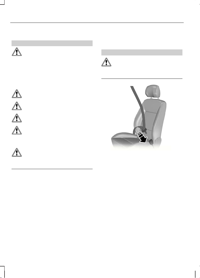
Third row seat belts
WARNING
On the S-MAX, do not release
the third row seat belts from the
floor lugs. If the seat belts are not
correctly re-latched to the floor lugs,
the seat belt may not provide
optimum protection for the seat
occupant in the event of an accident.
Releasing the belts from the
floor lugs (Galaxy)
Note:
You can use the floor lugs to
secure luggage with cords.
Note:
Move the third row seats
forwards to gain access to the floor
lugs.
E73136
1
30
Occupant protection
Page 33

E73137
2
1.
Press the spring hook (1) and
unhook it downwards.
2. Let the belt retract and push the
hook into the retainer on the trim
panel until it engages with an
audible click (2).
Latching the belts to the floor
lugs
WARNING
After latching the seat belt to the
floor lug, pull the belt to ensure
that it is latched correctly.
1. Pull the belt out of the retainer on
the trim panel.
2. Slide the spring hook down and
latch it in the lug with the spring
hook facing away from the seat.
SEAT BELT HEIGHT ADJUSTMENT
E73135
To raise the height, grasp the D-ring
and move the pivot up.
To lower the height, grasp the D-ring,
hold the locking button on the height
adjuster pressed and move the pivot
down.
Note:
Lifting the slider slightly while
pressing the locking button makes it
easier to release the locking
mechanism.
31
Occupant protection
Page 34

SEAT BELT REMINDER
WARNING
Do not sit on top of a fastened
seat belt to prevent the seat belt
reminder from coming on. The
occupant protection system will only
provide optimum protection when
you use the seat belt properly.
The seat belt reminder
warning lamp will come on
and an audible warning will
sound if you or your front seat
passenger have not fastened your
seat belts and the vehicle exceeds
10 km/h (6 mph). It will also come on
if your seat belts are unfastened
when the vehicle is moving. The
audible warning will go off after five
minutes but the seat belt reminder
warning lamp will remain on until you
fasten your seat belts.
Deactivating the seat belt
reminder
You can have the seat belt reminder
deactivated by your Ford dealer.
USING SEAT BELTS DURING PREGNANCY
E68587
WARNING
Position the seat belt correctly
for your safety and that of your
unborn child. Do not use only the lap
strap or the shoulder strap.
Position the lap strap comfortably
across your hips and low beneath
your pregnant abdomen. Position the
shoulder strap between your breasts,
above and to the side of your
pregnant abdomen.
DISABLING THE PASSENGER AIRBAG
WARNING
Make sure the passenger airbag
is disabled when using a
rearward facing child restraint on the
front passenger seat.
32
Occupant protection
Page 35

E71313
Fitting the passenger
airbag deactivation switch
WARNING
If you need to fit a child restraint
on a seat protected by an
operational airbag in front of it, have
a passenger airbag deactivation
switch fitted. Ask your dealer for
further information.
Note:
The key switch is located in
the glove compartment with an
airbag deactivation lamp in the
instrument panel.
If the airbag warning lamp comes on
or flashes when you are driving, this
indicates a malfunction. See
Warning lamps and indicators
(page 84). Remove the child restraint
and have this checked immediately.
Disabling the passenger
airbag
A B
E71312
DisabledA
EnabledB
Turn the switch to position A.
When you switch the ignition on,
check that the passenger airbag
deactivation warning lamp comes on.
Enabling the passenger
airbag
WARNING
Make sure the passenger airbag
is enabled when you are not
using a child restraint on the front
passenger seat.
Turn the switch to position B.
33
Occupant protection
Page 36

USING THE KEY
Remote control with flip key
blade
E74382
GENERAL INFORMATION ON RADIO FREQUENCIES
CAUTION
The radio frequency used by
your remote control can also be
used by other short distance radio
transmissions (e.g. amateur radios,
medical equipment, wireless
headphones, remote controls and
alarm systems). If the frequencies are
jammed, you will not be able to use
your remote control. You can lock
and unlock the doors with the key.
Note:
You could unlock the doors if
you press the buttons on the remote
control unintentionally.
The operating range between your
remote control and your vehicle
varies depending on the
environment.
PROGRAMMING THE REMOTE CONTROL
You can programme a maximum of
eight remote controls to use with
your vehicle (including any supplied
with your vehicle). Ask your dealer for
instructions.
CHANGING THE REMOTE CONTROL BATTERY
Remote control with a
folding key blade
E74383
1
1. Insert a screwdriver as far as
possible into the slot on the side
of the remote control, push it
towards the key blade and
remove the key blade.
34
Keys and remote controls
Page 37

E74384
2
2. Twist the screwdriver in the
position shown to start separating
the two halves of the remote
control.
3
E74385
3. Twist the screwdriver in the
position shown to separate the
two halves of the remote control.
CAUTION
Do not touch the battery
contacts or the printed circuit
board with the screwdriver.
4. Carefully prise out the battery with
the screwdriver.
5. Install a new battery (3V CR 2032)
with the + facing downwards.
6. Assemble the two halves of the
remote control.
7. Install the key blade.
Remote control without a
folding key blade
E74386
1. Insert a screwdriver into the
recess on the back of the key and
remove the key blade.
2. Release the retaining clips with
the screwdriver and separate the
two halves of the remote control.
CAUTION
Do not touch the battery
contacts or the printed circuit
board with the screwdriver.
3. Carefully prise out the battery with
the screwdriver.
4. Install a new battery (3V CR 2032)
with the + facing downwards.
5. Assemble the two halves of the
remote control.
6. Install the key blade.
35
Keys and remote controls
Page 38

LOCKING AND UNLOCKING
Central locking
You can only centrally lock the doors
if they are all closed.
Note:
The driver’s door can be
unlocked with the key. This needs to
be used if the remote control or
keyless entry is not functioning.
Note:
Central locking also locks and
unlocks the fuel filler flap.
Double locking
WARNINGS
Do not activate double locking
when persons or animals are
inside the vehicle.
You will not be able to unlock
the doors from the inside if you
have double locked them.
E71961
Double locking is a theft protection
feature that prevents someone from
opening the doors from the inside.
You can only double lock the doors
if they are all closed.
Locking and unlocking
confirmation
When you unlock the doors, the
direction indicators will flash once.
When you lock the doors, the
direction indicators will flash twice.
Note:
The direction indicators will
flash twice as soon as you activate
central locking. They will not flash
again when you press the lock button
on the remote control or turn the key
for the second time, i.e. when you
activate double locking.
36
Locks
Page 39

Locking and unlocking the
doors with the key
B
E71962
A
B
A
UnlockA
LockB
Double locking the doors with
the key
Turn the key to the lock position
twice within three seconds to double
lock the doors.
Locking and unlocking the
doors with the remote
control
E87379
A B C
UnlockA
LockB
Luggage compartment lid
unlock
C
Locking the doors with the
remote control
Press button B once.
Double locking the doors with
the remote control
Press button B twice within three
seconds.
37
Locks
Page 40

Locking and unlocking the
doors from inside
Front doors
E71958
A
B
Lock all doorsA
Unlock all doorsB
Rear doors
To lock the rear doors individually,
press button A and close the door
when leaving the vehicle.
Luggage compartment lid
Unlocking the luggage
compartment lid
Press button C on the remote control
twice within three seconds.
Closing the luggage
compartment lid
E71960
A recessed grip is incorporated inside
the luggage compartment lid to
facilitate closing.
Automatic relocking
The doors will relock automatically if
you do not open a door within 45
seconds of unlocking the doors with
the remote control. The door locks
and the alarm will return to their
previous state.
Reprogramming the
unlocking function
If the unlocking function is
reprogrammed so that only the
driver’s door is unlocked ( See Keys
and remote controls (page 34).
), note the following:
When you press the unlock button
either all the doors are unlocked or
only the driver’s door is unlocked.
Pressing the unlock button again
unlocks all the doors.
38
Locks
Page 41

GLOBAL OPENING AND CLOSING
You can also operate the electric
windows with the ignition off via the
global opening and global closing
function.
Note:
Global closing will only operate
if you have set the memory correctly
for each window. See Electric
windows (page 76).
Global opening
E71955
To open all the windows, press and
hold the unlock button for at least
three seconds. Press either the lock
or the unlock button again to stop
the opening function.
Global closing
WARNING
Take care when using global
closing. In an emergency, press
a button immediately to stop.
E71956
To close all the windows, press and
hold the lock button for at least two
seconds. Press any button again to
stop the closing function. The
anti-trap function is also active during
global closing.
KEYLESS ENTRY
General information
WARNING
The keyless entry system may
not function if the key is close to
metal objects or electronic devices
such as mobile phones.
Note:
If the door handles are pulled
repeatedly during a short period of
time without the presence of a valid
passive key, the system will become
inoperable for 30 seconds.
39
Locks
Page 42

The passive entry system will not
function if:
•
The passive key frequencies are
jammed.
•
The passive key battery is flat.
Note:
If the passive entry system
does not function, you will need to
use the key blade to lock and unlock
your vehicle.
The keyless system allows the driver
to operate the vehicle without the
use of a key or remote control.
E78276
Passive locking and unlocking
requires a valid passive key to be
located within one of the three
external detection ranges. These are
located approximately one and a half
metres from the driver and front
passenger door handles and the
luggage compartment lid.
Passive key
The vehicle can be locked and
unlocked with the passive key. The
passive key can also be used as a
remote control. See Locking and
unlocking (page 36).
Locking the vehicle
E87384
E87435
WARNING
The vehicle does not lock itself
automatically. If no locking
button is pressed, the vehicle will
remain unlocked.
40
Locks
Page 43

Note:
If locking from the luggage
compartment lid, the passive key
must be within the luggage
compartment lid detection range.
Locking buttons are located on each
of the front doors and the luggage
compartment lid.
To activate central locking and arm
the alarm:
•
Press a locking button once.
To activate double locking, to arm
the alarm and the interior sensors:
•
Press a locking button twice within
three seconds.
Note:
Once activated, the vehicle
will remain locked for approximately
three seconds. This is to allow you to
pull a door handle and check if the
vehicle is locked. When the delay
period is over, the doors can be
opened again, provided the passive
key is within the respective detection
range.
Luggage compartment lid
Note:
The luggage compartment lid
cannot be closed and will pop back
up if the passive key is located inside
the luggage compartment.
Note:
If a second valid passive key
is located within the luggage
compartment lid detection range, the
luggage compartment lid can be
closed.
Unlocking the vehicle
Note:
If the vehicle remains locked
for longer than five days, the key free
system will enter an energy-saving
mode. This is to reduce the discharge
of the vehicle battery. When the
vehicle is unlocked while in this mode,
the reaction time of the system may
be a little longer than normal.
Unlocking the vehicle once will
deactivate the energy-saving mode.
E78278
Pull one of the door handles or the
luggage compartment lid handle.
Note:
A valid passive key must be
located within the detection range of
that door.
One long flash of the direction
indicators confirms that all the doors,
the luggage compartment lid and the
fuel filler flap have been unlocked and
that the alarm has been disarmed.
41
Locks
Page 44

Unlocking only the driver's
door
If the unlocking function is
reprogrammed so that only the
driver’s door is unlocked ( See Keys
and remote controls (page 34).
), note the following:
If the driver’s door is the first door
which is opened, the other doors and
the luggage compartment lid will
remain locked. All the other doors
can be unlocked from inside the
vehicle by pressing the unlock button
next to the driver’s door handle.
Doors can be unlocked individually
by pulling the interior door handles
on those doors.
If the front passenger door or one of
the rear doors is the first door which
is opened, all the doors and the
luggage compartment lid will be
unlocked.
Disabled keys
Any keys left inside the vehicle interior
when it is locked will be disabled.
A disabled key cannot be used to
turn the ignition on or start the
engine.
In order to use these passive keys
again, they have to be enabled.
To enable all your passive keys,
unlock the vehicle using a passive
key or the remote control unlocking
function.
All passive keys will then be enabled
if the ignition is turned on or the
vehicle is started using a valid key.
Locking and unlocking the
doors with the key blade
Type 1
1
2
E78284
1. Slide the release slider in the
direction of the arrow and pull out
the key blade with your thumb.
2. Remove the key blade and insert
it into the lock.
Type 2
1
2
E87964
1. Carefully remove the cover.
42
Locks
Page 45

2. Remove the key blade and insert
it into the lock.
43
Locks
Page 46

PRINCIPLE OF OPERATION
The engine immobiliser is a theft
protection system that prevents
someone from starting the engine
with an incorrectly coded key.
CODED KEYS
Note:
Do not shield your keys with
metal objects. This may prevent the
receiver from recognising your key
as a valid one.
Note:
Have all of your remaining
keys erased and recoded if you lose
a key. Ask your dealer for further
information. Have replacement keys
recoded together with your existing
keys.
If you lose a key, you can obtain a
replacement from your Ford Dealer.
If possible, provide them with the key
number from the tag provided with
the original keys. You can also obtain
additional keys from your Ford
Dealer.
ARMING THE ENGINE IMMOBILISER
The engine immobiliser is armed
automatically one second after you
have switched the ignition off.
DISARMING THE ENGINE IMMOBILISER
The engine immobiliser is disarmed
automatically when you switch the
ignition on with a correctly coded key.
If the message Immobiliser active
appears in the information display,
your key has not been recognised.
Remove the key and try again.
If you are unable to start the engine
with a correctly coded key, this
indicates a malfunction. The
message Immobiliser active will
appear in the information display
when you switch on the ignition.
Have the immobiliser checked
immediately.
44
Engine immobiliser
Page 47

PRINCIPLE OF OPERATION
Alarm system
Your vehicle may be equipped with
one of the following alarm systems:
•
Perimeter alarm.
•
Perimeter alarm with interior
sensors.
•
Category one alarm with interior
sensors and battery back-up
sounder.
•
Category one alarm with interior
sensors, battery back-up sounder
and tilt sensors.
Perimeter alarm
The perimeter alarm is a deterrent
against unauthorised access to your
vehicle through the doors and the
bonnet. It also protects the audio unit.
Interior sensors
E71401
WARNING
The sensors in the interior lamp
unit must not be covered up. Do
not activate the alarm with full guard
if any persons, animals or other
moving objects are inside the vehicle.
The sensors act as a deterrent
against unauthorised intrusion by
sensing any movement within the
vehicle.
Battery back-up sounder
The battery back-up sounder is an
extra alarm system which will sound
a siren when the alarm is triggered.
It is armed directly when you lock the
vehicle. The sounder has its own
battery and will sound an alarm siren
even if someone disconnects the
vehicle battery or the battery back-up
sounder itself.
Tilt sensors
The tilt sensors detect if someone
attempts to steal a wheel or tow the
vehicle away by sensing changes in
the inclination of the vehicle.
Note:
When travelling on a ferry with
the alarm armed, deactivate the tilt
sensors by selecting reduced guard.
This will prevent the alarm from being
triggered by the movement.
Triggering the alarm
Once armed, the alarm is triggered
in any of the following ways:
•
If someone opens a door, the
tailgate or the bonnet without a
valid key or remote control.
•
If someone removes the audio or
navigation system.
•
On vehicles without keyless
starting, if the ignition is turned to
position I, II or III without a valid
key.
45
Alarm
Page 48

•
If the interior sensors detect
movement within the vehicle.
•
On vehicles with a battery
back-up sounder, if someone
disconnects the vehicle battery or
the battery back-up sounder itself.
•
If the tilt sensors detect a change
in the inclination of the vehicle.
If the alarm is triggered, the alarm
horn will sound for 30 seconds and
the hazard warning flasher will flash
for five minutes.
Any further attempts to perform one
of the above will trigger the alarm
again.
Full and reduced guard
Full guard
Full guard is the standard setting.
In full guard, the interior and tilt
sensors are activated when you arm
the alarm.
Note:
This may result in false alarms
if animals or moving objects are
inside the vehicle or, on vehicles with
tilt sensors, when travelling on a ferry.
Reduced guard
In reduced guard, the interior and tilt
sensors are deactivated when you
arm the alarm.
Note:
You can set the alarm to
reduced guard for the current ignition
cycle only. The next time you switch
on the ignition, the alarm will be reset
to full guard.
Ask on Exit
You can set the information display
to ask you each time which level of
guard you wish to set.
If you select Ask on Exit, the
message Reduced guard?
appears in the instrument cluster
display each time you switch the
ignition off.
If you wish to arm the alarm with
reduced guard, press the OK button
when this message appears.
If you wish to arm the alarm with full
guard, leave the vehicle without
pressing the OK button.
Selecting full or reduced guard
Note:
Selecting Reduced does not
set the alarm permanently to
reduced guard. It sets it to reduced
guard only for the current ignition
cycle. If you regularly set the alarm to
reduced guard, select Ask on Exit.
E70499
46
Alarm
Page 49

E74509
Full Guard
Alarm
Reduced
Ask on Exit
1. Press the right arrow button on
the steering wheel to enter the
main menu.
2.
Highlight Setup with the up and
down arrow buttons and press
the right arrow button.
3.
Highlight Alarm and press the
right arrow button.
4.
Highlight Reduced or Full
guard. If you prefer to be asked
each time you switch off the
ignition, select Ask on Exit.
5.
Press the OK button to confirm
the selection.
6. Press the left arrow button to exit
the menu. To return to the trip
computer display directly, hold the
left arrow button pressed.
Information messages
See Information messages
(page 102).
ARMING THE ALARM
All vehicles
To arm the alarm, lock the vehicle
with the key or remote control.
DISARMING THE ALARM
Vehicles without keyless
entry
Perimeter alarm
Disarm and silence the alarm by
unlocking the doors with the key and
switching the ignition on with a
correctly coded key, or unlocking the
doors or the luggage compartment
lid with the remote control.
Category one alarm
Disarm and silence the alarm by
unlocking the doors with the key and
switching the ignition on with a
correctly coded key within 12
seconds, or unlocking the doors or
the luggage compartment lid with the
remote control.
Vehicles with keyless entry
Note:
A valid passive key must be
located within the detection range of
that door for keyless entry. See
Keyless entry (page 39).
47
Alarm
Page 50

Perimeter alarm
Disarm and silence the alarm by
unlocking the doors and switching
the ignition on, or unlocking the doors
or the luggage compartment lid with
the remote control.
Category one alarm
Disarm and silence the alarm by
unlocking the doors and switching
the ignition on within 12 seconds, or
unlocking the doors or the tailgate
with the remote control.
48
Alarm
Page 51

ADJUSTING THE STEERING WHEEL
WARNING
Never adjust the steering wheel
when the vehicle is moving.
E71221
Release the locking lever to adjust
the height of the steering wheel and
its distance from the driver.
Return the lever to its original position
to secure the wheel.
Ensure that you are sitting in the
correct position. See Sitting in the
correct position (page 127).
AUDIO CONTROL
A
C
B
D
E
E72288
Volume upA
Seek upB
Volume downC
Seek downD
ModeE
Mode
Press and hold the mode button to
select the audio source.
Press the mode button to:
•
tune the radio to the next preset
station
•
play the next CD
•
play the other side of a cassette
tape
•
accept an incoming telephone
call.
•
end a telephone call.
49
Steering wheel
Page 52

Seek
Press a seek button to:
•
tune the radio to the next station
up or down the frequency band
•
play the next or the previous CD
track
•
fast forward or rewind the
cassette tape.
Press and hold a seek button to:
•
tune the radio up or down the
frequency band
•
seek through a CD track.
50
Steering wheel
Page 53

WINDSCREEN WIPERS
B
C
D
A
E70696
Single wipeA
Intermittent wipeB
Normal wipeC
High speed wipeD
Intermittent wipe
E70315
B
A
C
Short wipe intervalA
Intermittent wipeB
Long wipe intervalC
AUTOWIPERS
E76677
B
CAUTIONS
Do not switch autowipers on in
dry weather conditions. The rain
sensor is very sensitive and the
wipers may operate if dirt, mist or flies
hit the windscreen.
Replace the wiper blades as
soon as they begin to leave
bands of water and smears. If you do
not replace them, the rain sensor will
continue to detect water on the
windscreen and the wipers will
operate, even though the majority of
the windscreen is dry.
Fully defrost the windscreen in
icy conditions before you switch
autowipers on.
Switch autowipers off before you
enter a car wash.
51
Wipers and washers
Page 54

If you switch autowipers on, the
wipers will not cycle until water is
detected on the windscreen. The rain
sensor will then continuously
measure the amount of water on the
windscreen and adjust the speed of
the wipers automatically.
RAIN SENSOR
E70316
A
B
High sensitivityA
Low sensitivityB
Adjust the sensitivity of the rain
sensor using the rotary control. If you
set the control to low sensitivity, the
wipers will operate when the sensor
detects a lot of water on the
windscreen. If you set the control to
high sensitivity, the wipers will
operate if the sensor detects a small
amount of water on the windscreen.
WINDSCREEN WASHERS
WARNING
Do not operate the windscreen
washers for more than 10
seconds or when the reservoir is
empty.
Note:
The washer jets are heated
when the ignition is on.
E70776
REAR WINDOW WIPER AND WASHERS
Intermittent wipe
E70777
52
Wipers and washers
Page 55

Reverse gear wipe
The rear window wiper will operate
automatically when you select
reverse gear if the wiper lever is in
position B, C or D.
Washer
WARNING
Do not operate the rear window
washer for more than 10
seconds or when the reservoir is
empty.
E70777
Pull the lever fully towards the
steering wheel and hold it to operate
the washer.
HEADLAMP WASHERS
E70776
The headlamp washers will operate
with the windscreen washers when
the headlamps are on.
Note:
To stop the washer fluid
reservoir emptying quickly, the
headlamp washers will not operate
every time that you use the
windscreen washers.
CHECKING THE WIPER BLADES
E66644
Run the tip of your fingers over the
edge of the blade to check for
roughness.
53
Wipers and washers
Page 56

Clean the wiper blade lips with water
applied with a soft sponge.
CHANGING THE WIPER BLADES
Windscreen wiper blades
CAUTIONS
Set the windscreen wipers in the
service position to change the
wiper blades.
You can use the service position
in winter to provide easier access
to the wiper blades for freeing them
from snow and ice. The windscreen
wipers will return to their normal
position as soon as you switch on the
ignition so make sure that you fully
defrost the windscreen before you
switch on the ignition.
Setting the windscreen wipers
in the service position
E75184
A
E75188
Switch off the ignition and move the
wiper lever to position A within three
seconds. Release the lever when the
windscreen wipers have moved to
the service position.
Changing the windscreen
wiper blades
E72899
1
2
Note:
The windscreen wiper blades
are different lengths. See Technical
specifications (page 55). If you
install wiper blades of the wrong
length, the rain sensor may not work
correctly.
Set the windscreen wipers in the
service position and lift the wiper
arms.
1. Press the locking button.
2. Remove the wiper blade.
54
Wipers and washers
Page 57

Note:
Make sure that the wiper
blade locks into place.
Install in the reverse order.
Rear window wiper blades
E66645
5
2
4
3
1
Lift the wiper arm.
1. Position the wiper blade at right
angles to the wiper arm.
2. Press the retaining clip.
3. Disengage the wiper blade from
the wiper arm.
4. Move the wiper blade sideways.
5. Remove the wiper blade.
Install in the reverse order.
TECHNICAL SPECIFICATIONS
Windscreen wiper blade lengths
Dimension in mm (inches)
Item
Right-handLeft-hand
700 (27.6)750 (29.5)Vehicles with a rain
sensor
650 (25.6)750 (29.5)Vehicles without a rain
sensor
55
Wipers and washers
Page 58

LIGHTING CONTROL
Lighting control positions
BA C
E70718
OffA
Side and tail lampsB
HeadlampsC
Parking lamps
CAUTION
Prolonged use of the parking
lamps will discharge the battery.
Switch off the ignition.
Both sides
Set the lighting control to position B.
One side
E75505
A
B
Right-hand sideA
Left-hand sideB
Main and dipped beam
E70725
Pull the lever fully towards the
steering wheel to switch between
main and dipped beam.
Headlamp flasher
Pull the lever slightly towards the
steering wheel.
56
Lighting
Page 59

Home safe lighting
Switch off the ignition and pull the
direction indicator lever fully towards
the steering wheel to switch the
headlamps on. The headlamps will
go off automatically 30 seconds after
you have closed the last door.
AUTOLAMPS
E70719
Note:
If you have switched
autolamps on, you can only switch
the main beam on when autolamps
has switched the headlamps on.
The headlamps will come on and go
off automatically depending on the
ambient light.
FRONT FOG LAMPS
E70721
WARNING
Only use the front fog lamps
when visibility is considerably
restricted by fog, snow or rain.
REAR FOG LAMPS
E70720
WARNINGS
Only use the rear fog lamps
when visibility is restricted to less
than 50 metres.
Do not use the rear fog lamps
when it is raining or snowing and
visibility is more than 50 metres.
57
Lighting
Page 60

HEADLAMP LEVELLING
E70722
A
B
Raised headlamp beamsA
Lowered headlamp beamsB
You can adjust the level of the
headlamp beams according to the
vehicle load.
Note:
Vehicles with Xenon
headlamps are equipped with
automatic headlamp levelling.
Recommended headlamp levelling switch positions
Switch posi-
tion
Load in
luggage
compart-
ment
Load
Third row
seats
Second row
seats
Front seats
0---1-2
0 (0.52)
-2-1-2
1 (0.52)
--31-2
3 (0.52)Max
1
-31-2
4 (1.52)Max
1
--1
1
See Technical specifications (page 257).
2
Vehicles with active suspension.
58
Lighting
Page 61

HAZARD WARNING FLASHERS
E71943
Note:
You can also operate the
hazard warning flashers when the
ignition is off.
Note:
Depending on applicable laws
and regulations in the country for
which your vehicle was originally built,
the hazard warning flashers will flash
if you brake heavily.
ADAPTIVE FRONT LIGHTING SYSTEM (AFS)
E72897
A
B
A
B
without AFSA
with AFSB
59
Lighting
Page 62

The AFS adjusts the headlamp
dipped beam depending on vehicle
direction and speed. It improves
visibility when you are driving at night
and helps to reduce headlamp glare
for oncoming drivers.
The system will not operate when the
vehicle is stationary, when you have
switched on the daytime running
lamps or when you have selected
reverse gear.
A message will appear in the
information display if the system
malfunctions. See Information
messages (page 102). The
headlamps will move to a fixed
central or dipped position. Have the
system checked as soon as possible.
Cornering lamps
E72898
B
A
B
A
Headlamp beamA
Cornering lamp beamB
The cornering lamps illuminate the
inside of a corner when you are
turning.
60
Lighting
Page 63

DIRECTION INDICATORS
E70727
Note:
Tap the lever up or down to
make the direction indicators flash
only three times.
INTERIOR LAMPS
Courtesy lamp
C
B
A
E71945
OffA
Door contactB
OnC
If you set the switch to position B, the
courtesy lamp will come on when you
unlock or open a door or the tailgate.
If you leave a door open with the
ignition switch off, the courtesy lamp
will go off automatically after some
time to prevent the vehicle battery
from discharging. To switch it back
on, switch on the ignition for a short
time.
The courtesy lamp will also come on
when you switch off the ignition. It will
go off automatically after a short time
or when you start or restart the
engine.
If you set the switch to position C
with the ignition switch off, the
courtesy lamp will come on. It will go
off automatically after a short time to
prevent the vehicle battery from
discharging. To switch it back on,
switch on the ignition for a short time.
Reading lamps
E71946
If you switch off the ignition, the
reading lamps will go off automatically
after some time to prevent the
vehicle battery from discharging. To
switch them back on, switch on the
ignition for a short time.
61
Lighting
Page 64

Vanity mirror lamps
A
B
E72900
OffA
OnB
If you switch off the ignition, the vanity
mirror lamps will go off automatically
after a short time to prevent the
vehicle battery from discharging. To
switch them back on, switch on the
ignition for a short time.
REMOVING A HEADLAMP
1.
Open the bonnet. See Opening
and closing the bonnet (page
225).
E72257
Note:
When you remove the
headlamp, make sure the front screw
remains in the headlamp moulding.
2. Remove the screws.
E88875
3. Disconnect the electrical
connector.
4. Pull the headlamp as far as
possible towards the centre of the
vehicle and disengage it from the
lower fixing point.
5. Lift the outer side of the headlamp
and remove it.
62
Lighting
Page 65

Note:
When fitting the headlamp,
make sure that you reconnect the
electrical connector properly.
Note:
When fitting the headlamp,
make sure that you fully engage the
headlamp in the lower fixing point.
Note:
When fitting the headlamp,
place the front screw into the
headlamp unit before you install it.
Tighten the front screw first and then
the rear screw.
CHANGING A BULB
WARNINGS
Switch off the lights and the
ignition.
Let the bulb cool down before
removing it.
Have Xenon bulbs changed by
a trained technician. There is a
risk of electric shock.
CAUTIONS
Do not touch the glass of the
bulb.
Only fit bulbs of the correct
specification. See Bulb
specification chart (page 75).
Headlamp
A B C D
E72258
Direction indicatorA
Headlamp main beamB
Headlamp dipped beamC
Cornering lampD
Remove the covers to gain access
to the headlamp and cornering lamp
bulbs.
Direction indicator
1. Remove the headlamp. See
Removing a headlamp (page
62).
E72259
2
3
63
Lighting
Page 66

2. Turn the bulb holder
anti-clockwise and remove it.
3. Gently press the bulb into the bulb
holder, turn it anti-clockwise and
remove it.
Note:
When installing the bulb, pay
attention to the guide tabs.
4. Install in the reverse order.
Headlamp main beam
1. Remove the headlamp. See
Removing a headlamp (page
62).
E72261
3
2
2. Disconnect the electrical
connector.
3. Release the clip and remove the
bulb.
4. Install in the reverse order.
Headlamp dipped beam
1. Remove the headlamp. See
Removing a headlamp (page
62).
E72260
3
2
2. Turn the bulb holder
anti-clockwise and remove it.
3. Remove the bulb.
4. Install in the reverse order.
Cornering lamp
1. Remove the headlamp. See
Removing a headlamp (page
62).
E72262
3
2
2. Disconnect the electrical
connector.
3. Release the clip and remove the
bulb.
4. Install in the reverse order.
64
Lighting
Page 67

Side repeater
E72263
1. Remove the lamp.
E72291
2. Remove the bulb holder.
3. Remove the bulb.
Note:
Make sure that the lamp clicks
back into place.
4. Install in the reverse order.
Approach lamp
E72264
1
Note:
Position the mirror glass as far
inwards as possible.
1. Insert a screwdriver into the gap
between the mirror housing and
the mirror glass and release the
metal retaining clip.
E72265
3
2
2. Remove the lamp.
3. Remove the bulb.
4. Install in the reverse order.
65
Lighting
Page 68

Front fog lamp and side
lamp (S-MAX)
E72266
1. Remove the trim.
E72268
2. Release the clip at the top edge
of the lamp using a screwdriver.
3. Remove the lamp.
E74542
5
4
6
7
8
Note:
You cannot separate the fog
lamp bulb from the bulb holder.
4. Disconnect the fog lamp electrical
connector.
5. Turn the fog lamp bulb holder
anti-clockwise and remove it.
6. Disconnect the side lamp
electrical connector.
7. Turn the side lamp bulb holder
anti-clockwise and remove it.
8. Remove the side lamp bulb.
9. Install in the reverse order.
66
Lighting
Page 69

Front fog lamp and side
lamp (Galaxy)
E72267
3
2
4
1
1. Remove the screws.
2. Remove the lamp.
3. Disconnect the fog lamp electrical
connector.
Note:
You cannot separate the fog
lamp bulb from the bulb holder.
4. Turn the fog lamp bulb holder
anti-clockwise and remove it.
E72269
6
5
5. Turn the side lamp bulb holder
anti-clockwise and remove it.
6. Remove the side lamp bulb.
7. Install in the reverse order.
Rear lamp (S-MAX)
Direction indicator and brake
and tail lamp
E74078
1. Remove the trim panels.
E72270
2. Remove the wing nuts.
67
Lighting
Page 70

E74079
3. Remove the lamp.
4. Disconnect the electrical
connector.
E74080
5. Remove the screw.
6. Remove the bulb holder.
7. Gently press the bulb into the bulb
holder, turn it anti-clockwise and
remove it.
8. Install in the reverse order.
Reversing lamp, fog lamp and
tail lamp
E72271
1. Remove the trim panel.
E74076
2. Remove the wing nuts using a
coin.
3. Remove the lamp.
4. Disconnect the electrical
connector.
68
Lighting
Page 71

E74077
5. Remove the screw.
6. Remove the bulb holder.
7. Gently press the bulb into the bulb
holder, turn it anti-clockwise and
remove it.
8. Install in the reverse order.
Rear lamp (Galaxy)
Direction indicator, brake lamp
and tail lamp
E75380
1. Remove the trim panel.
E72791
2. Remove the wing nuts.
E72792
3. Remove the lamp.
4. Disconnect the electrical
connector.
69
Lighting
Page 72

E72793
5. Remove the screw.
6. Remove the bulb holder.
7. Gently press the bulb into the bulb
holder, turn it anti-clockwise and
remove it.
8. Install in the reverse order.
Reversing lamp, fog lamp and
tail lamp
E72794
1. Remove the trim panel.
E72795
2. Remove the wing nuts using a
coin.
3. Remove the lamp.
4. Disconnect the electrical
connector.
E72797
5. Turn the bulb holder
anti-clockwise and remove it.
70
Lighting
Page 73

E72798
6. Remove the screws.
7. Remove the bulb holder.
8. Gently press the bulb into the bulb
holder, turn it anti-clockwise and
remove it.
9. Install in the reverse order.
Central high mounted brake
lamp (S-MAX)
E75459
1. Remove the trim panel.
E75460
2. Release the spring clips using a
screwdriver.
E72790
3. Remove the lamp.
4. Remove the bulb.
Note:
Make sure that the lamp clips
into place.
5. Install in the reverse order.
71
Lighting
Page 74

Central high mounted brake
lamp (Galaxy)
E75457
1. Remove the trim panel.
E75458
2. Release the spring clips using a
screwdriver.
E72790
3. Remove the lamp.
4. Remove the bulb.
Note:
Make sure that the lamp clips
into place.
5. Install in the reverse order.
Number plate lamp
E72789
1. Release the spring clip using a
small screwdriver.
2. Remove the lamp.
3. Turn the bulb anti-clockwise and
remove it.
Note:
Insert the end the lamp
without the spring clip first.
4. Install in the reverse order.
Interior and reading lamps
•
•
72
Lighting
Page 75

Interior lamp (vehicles without
interior sensors)
E72788
1. Carefully prise out the lens using
a flat-bladed screwdriver.
2. Remove the lens.
3. Remove the bulb.
4. Install in the reverse order.
Interior lamp (vehicles with
interior sensors)
E72787
1. Carefully prise out the lens using
a flat-bladed screwdriver.
2. Remove the lens.
3. Remove the bulb.
4. Install in the reverse order.
Reading lamp (vehicles
without interior sensors)
E72796
1. Carefully prise out the lens using
a flat-bladed screwdriver.
2. Remove the lens.
3. Turn the bulb holder
anti-clockwise and remove it.
4. Install in the reverse order.
73
Lighting
Page 76

Reading lamp (vehicles with
interior sensors)
E72786
1. Carefully prise out the lamp using
a flat-bladed screwdriver.
2. Turn the bulb holder
anti-clockwise and remove it.
3. Install in the reverse order.
Vanity mirror lamp
E72785
1. Carefully prise out the lamp using
a flat-bladed screwdriver.
2. Remove the bulb.
3. Install in the reverse order.
Luggage compartment
lamp
E72784
1. Carefully prise out the lamp using
a flat-bladed screwdriver.
2. Remove the bulb.
3. Install in the reverse order.
74
Lighting
Page 77

BULB SPECIFICATION CHART
Power (watt)SpecificationLamp
21PY21WFront direction indicator
55H1Headlamp main beam
55H7Headlamp dipped beam
55H1Cornering lamp
5WY5WSide repeater
5W5Approach lamp
35H8Front fog lamp (S-MAX)
55HB4Front fog lamp (Galaxy)
5W5WSide lamp
21PY21WRear direction indicator
21/5P21/5WBrake and tail lamp (S-MAX)
21P21WBrake lamp (Galaxy)
5W5WTail lamp (Galaxy)
21P21WRear fog lamp
21P21WReversing lamp
16W16WCentral high mounted brake lamp
5C5WNumber plate lamp
10FestoonInterior lamp
5BA 9sReading lamp
5W5WVanity mirror lamp
5W5WLuggage compartment lamp
75
Lighting
Page 78

ELECTRIC WINDOWS
WARNING
Do not operate the electric
windows unless they are free
from obstruction.
Note:
If you operate the switches
often during a short period of time,
the system might become inoperable
for a certain time to prevent damage
due to overheating.
Note:
You can operate the windows
for several minutes after you switch
off the ignition. They will be
deactivated as soon as a door is
opened.
Note:
If you operate both the switch
on the relevant door and the switch
for that window on the driver’s door
at the same time, the window will
stop moving.
Switch on the ignition to operate the
electric windows.
Global opening and global
closing
You can also operate the electric
windows with the ignition off via the
global opening and global closing
function. See Global opening and
closing (page 39).
Note:
Global opening and global
closing will open or close the
windows automatically only on
vehicles equipped with four electric
windows.
Note:
Global closing will only operate
if you have set the memory correctly
for each window.
Driver’s door switches
You can operate all the windows with
the switches on the door trim panel
of the driver’s door.
E70848
A
B
CloseA
OpenB
76
Windows and mirrors
Page 79

Front and rear passengers’
door switches
E70849
A
B
CloseA
OpenB
Opening and closing the
windows automatically
Press or lift the switch to the second
action point and release it. Press or
lift it again to stop the windows.
Safety switch for rear
windows
Note:
You can always operate the
rear windows from the driver’s door.
E70850
A switch in the driver’s door disables
the rear electric window switches.
The light in the switch comes on and
the lights in the rear window switches
go off when the rear windows are
disabled.
Anti-trap function
WARNING
Careless closing of the windows
can override the protection
function and cause injuries.
The electric windows will stop
automatically while closing and
reverse some distance if there is an
obstacle in the way.
77
Windows and mirrors
Page 80

Overriding the anti-trap
function
CAUTION
While you close the window for
the third time, the anti-trap
function is disabled. Make sure there
are no obstacles in the way of the
closing window.
To override this protection function
when there is a resistance, e.g. in the
winter, proceed as follows:
1. Close the window twice until it
reaches the resistance and let it
reverse.
2. Close the window a third time to
the resistance. The anti-trap
function is disabled and you
cannot close the window
automatically. The window will
override the resistance and you
can close it fully.
3. If the window does not close after
the third attempt, have it checked
by an expert.
Resetting the memory of
the electric windows
WARNING
The anti-trap function is
deactivated until you have reset
the memory.
After the battery has been
disconnected from the vehicle you
must reset the memory separately
for each window:
1. Lift the switch until the window is
fully closed. Hold the switch lifted
for one more second.
2. Release the switch and lift it again,
two or three times, for one more
second.
3. Open the window and try to close
it automatically.
4. Reset and repeat procedure if the
window does not close
automatically.
Safety mode
WARNING
The anti-trap function is not
active during this procedure.
If the system detects a malfunction,
it enters a safety mode. The windows
will move for only about 0.5 seconds
at a time and then stop again. Close
the windows by pressing the switch
again when the windows stop
moving. Have the system checked
by an expert immediately.
78
Windows and mirrors
Page 81

EXTERIOR MIRRORS
Convex outside mirrors
E71042
WARNING
Do not overestimate the
distance of the objects that you
see in the convex mirror. Objects
seen in convex mirrors will appear
smaller and further away than they
actually are.
The mirrors increase your rearward
field of vision to reduce the so-called
blind spot at the rear quarter of your
vehicle.
Folding outside mirrors
E71043
Make sure that you fully engage the
mirror in its support when returning
it to its original position.
ELECTRIC EXTERIOR MIRRORS
A C
B
E70846
Left-hand mirrorA
OffB
Right-hand mirrorC
79
Windows and mirrors
Page 82

Mirror tilting positions
D
F
EG
E70847
upD
rightE
downF
leftG
The electric exterior mirrors are fitted
with a heating element that will
defrost or demist the mirror glass.
See Heated windows and
mirrors (page 121).
Electric folding mirrors
The electric folding mirrors operate
with the ignition on.
Note:
You can operate the door
mirrors (mirror tilting and folding) for
several minutes after you switch off
the ignition. They will be deactivated
as soon as a door is opened.
E72623
Press the button to fold or unfold the
mirrors.
If you press the switch again while
the mirrors are moving, they will stop
and reverse the direction of
movement.
Note:
When the mirrors are
operated often during a short period
of time, the system might become
inoperable for a certain time to
prevent damage due to overheating.
Reverse mirror dipping
Depending on the selected mirror
position (A or C), the relevant exterior
mirror will dip whenever you select
reverse gear, giving you a view of the
kerb.
When you first use this feature, the
mirrors will dip to a preset position.
You can programme the degree of
dipping using the following sequence:
80
Windows and mirrors
Page 83

Note:
You can disable this feature
by leaving the electric exterior mirror
selector switch in position B.
The exterior mirrors will return to the
original position:
•
If the vehicle speed exceeds 10
km/h (6 mph).
•
Approximately 10 seconds after
reverse gear has been
disengaged.
•
If the electric exterior mirror
selector switch is returned to
position B.
Passive setting
1. Turn the ignition on. Do not start
the engine.
2. Select the desired exterior mirror
(A or C).
3. Select reverse gear, the selected
exterior mirror will adjust to a
preset position.
4. Adjust the mirrors to the required
dipped position. See Electric
exterior mirrors (page 79).
5. Disengage reverse gear.
The settings will be stored
automatically.
Active setting
1. Turn the ignition on. Do not start
the engine.
2. Select the desired exterior mirror
(A or C).
3. Select reverse gear, the selected
exterior mirror will adjust to a
preset position.
4. Adjust the mirror to the required
dipped position. See Electric
exterior mirrors (page 79).
5. Press and hold the desired
pre-set button until a single chime
sounds to confirm. See Memory
function (page 144).
INTERIOR MIRROR
E71272
Dip the mirror to reduce glare when
driving at night.
AUTO-DIMMING MIRROR
E71028
The auto-dimming mirror will adjust
automatically when hit by glaring light
from behind. It will not work when you
have selected reverse gear.
81
Windows and mirrors
Page 84

REAR QUARTER WINDOWS
Galaxy
E72126
To open, pull the lever, fold out the
window and press the lever to
engage it in its catch.
When closing, ensure that the lever
is securely engaged in its catch.
Electric rear quarter
windows
Switch on the ignition to operate the
rear quarter windows.
E72127
A
B
CloseA
OpenB
82
Windows and mirrors
Page 85

GAUGES
BA C D
E72984
TachometerA
Engine coolant temperature gaugeB
Fuel gaugeC
SpeedometerD
Engine coolant temperature
gauge
Shows the temperature of the engine
coolant. At normal operating
temperature, the needle will remain
in the centre section.
CAUTION
Do not restart the engine until the
cause of overheating has been
resolved.
83
Instruments
Page 86

If the needle moves towards 120°C,
the engine is overheating. Stop the
engine, switch the ignition off and
determine the cause once the
engine has cooled down. See
Engine coolant check (page 232).
Fuel gauge
The arrow adjacent to the fuel pump
symbol tells you on which side of
your vehicle the fuel filler cap is
located.
WARNING LAMPS AND INDICATORS
The following warning lamps and
indicators will come on briefly when
you switch the ignition on to confirm
that the system is operational:
•
ABS warning lamp
•
Airbag warning lamp
•
Brake system warning lamp
•
Engine warning lamp
•
EPB warning lamp
•
Frost warning lamp
•
Ignition warning lamp
•
Oil pressure warning lamp (all
except 2.5L Duratec-ST)
•
Stability control (ESP) warning
lamp
If a warning or indicator lamp does
not illuminate when the ignition is
switched on, it indicates a
malfunction. Have the system
checked by an expert.
ABS warning lamp
The ABS warning lamp will
flash when the system is
operating. If it comes on
when you are driving, this indicates
a malfunction. You will continue to
have normal braking (without ABS)
but have this checked as soon as
possible.
Airbag warning lamp
If the airbag warning lamp
comes on or flashes when
you are driving, this indicates
a malfunction. Have this checked as
soon as possible.
Brake system warning lamp
WARNING
Reduce your speed gradually.
Use your brakes with great care.
Do not step on the brake pedal
abruptly.
If the brake system warning
lamp comes on when you
are driving, this indicates a
malfunction in one of the brake
circuits. Check the brake fluid level.
See Brake and clutch fluid
check (page 233).
WARNING
Have this checked immediately.
84
Instruments
Page 87

If the brake system warning lamp
comes on with the ABS warning lamp
or the stability control warning lamp,
this indicates a malfunction. Stop your
vehicle as soon as it is safe to do so
and have this checked before
continuing you journey.
Cruise control indicator
E71340
The cruise control indicator
will come on when you have
set a speed using the cruise
control system. See Cruise
control (page 175). On vehicles with
Adaptive cruise control, the indicator
comes on when ACC is active. See
Adaptive cruise control (ACC)
(page 177).
Direction indicators
The direction indicator will
flash when you use the
direction indicators. A
sudden increase in the rate of
flashing warns of a failed bulb.
Engine warning lamp
If the engine warning lamp
comes on when the engine
is running, this indicates a
malfunction. If it flashes when you are
driving, reduce the speed of
your vehicle immediately. If it
continues to flash, avoid heavy
acceleration or deceleration. The
engine will continue to run but it will
have limited power. Have this
checked immediately.
Electric parking brake
(EPB) warning lamp
The EPB warning lamp will
come on when an EPB
warning message is
displayed in the information display.
See Electric parking brake
(EPB) (page 161).
Forward alert indicator
The forward alert indicator
will come on when this
feature is active. See
Forward alert function (page 181).
Front fog lamp indicator
The front fog lamp indicator
will come on when you
switch the front fog lamps
on.
Frost warning lamp
The frost warning lamp will
come on and glow orange
when the outside air
temperature is between 4ºC and 1ºC.
It will glow red when the temperature
is below 1ºC.
Glow plug indicator
See Starting a diesel
engine (page 151).
85
Instruments
Page 88

Headlamp indicator
The headlamp indicator will
come on when you switch
the headlamp dipped beam
or the side and tail lamps on.
Ignition warning lamp
If the ignition warning lamp
comes on when you are
driving, this indicates a
malfunction. Switch off all
unnecessary electrical equipment
and have this checked immediately.
Low fuel level warning lamp
If the low fuel level warning
lamp comes on, refuel as
soon as possible.
Main beam indicator
The main beam indicator will
come on when you switch
the headlamp main beam
on. It will flash when you use the
headlamp flasher.
Maximum engine speed
indicator
The maximum engine speed
indicator will come on when
the maximum engine speed
is reached.
Message indicator
The message indicator will
come on when a new
message is stored in the
information display. See
Information displays (page 88).
Oil pressure warning lamp
CAUTION
Do not resume your journey if the
oil pressure warning lamp comes
on despite the oil level being correct.
Have this checked immediately.
If the oil pressure warning
lamp comes on when you
are driving, this indicates a
malfunction. Stop your vehicle as
soon as it is safe to do so and switch
the engine off. Check the engine oil
level. See Engine oil check (page
231).
Rear fog lamp indicator
The rear fog lamp indicator
will come on when you
switch the rear fog lamps
on.
Seat belt reminder
See Seat belt reminder
(page 32).
86
Instruments
Page 89

Stability control (ESP)
warning lamp
Note:
If the ESP system
malfunctions, it will switch off
automatically.
The ESP warning lamp will
flash when system is
operating. If it does not flash
or it comes on when you are driving,
this indicates a malfunction. Have this
checked as soon as possible. See
Information messages (page
102).
If you switch ESP off, the warning
lamp will come on. The lamp will go
out when you switch the system
back on or when you switch the
ignition off.
AUDIBLE WARNINGS AND INDICATORS
Switching the chimes on
and off
You can deactivate certain chimes.
To set which chimes should sound:
E70499
1. Press the right arrow button on
the steering wheel to enter the
main menu.
2.
Highlight Setup with the up and
down arrow buttons and press
the right arrow button.
3.
Highlight Chimes and press the
right arrow button.
4. Highlight the chime and press the
OK button to switch the chime on
and off.
5. Press the left arrow button to exit
the menu. To return to the trip
computer display directly, hold the
left arrow button pressed.
87
Instruments
Page 90

GENERAL INFORMATION
WARNING
Do not operate the information
display controls when the
vehicle is moving.
Note:
The information display will
remain on for several minutes after
you switch off the ignition.
Various systems on your vehicle can
be controlled using the buttons on
your steering wheel. Corresponding
information is shown in the
instrument cluster display.
For detailed instructions on audio,
navigation, phone etc. refer to the
appropriate manual.
Controls
E70499
Press the up and down arrow
buttons:
•
to scroll through the trip computer
displays
•
to scroll through and highlight the
options within a menu.
Press the right arrow button:
•
to enter the main menu from the
trip computer displays
•
to enter a sub-menu.
Press the left arrow button to exit a
menu.
Hold the left arrow button pressed
at any time to return to the main
menu display (escape button).
Note:
The system will return to the
trip computer displays automatically
if you do not press any button for a
period of time.
Press the OK button to choose and
confirm a setting.
Instrument cluster functions
Type 3Type 2Type 1Function
XXXTrip computer
XXXInformation messages
88
Information displays
Page 91

Type 3Type 2Type 1Function
XXXClock setup
XX-Display settings
XX-Park heater setup
X--Navigation control
X--CD control
X--CD changer control
X--Radio control
X--Phone control
X--Auxiliary input control
Type 1
E80604
Use the up and down arrow buttons
to scroll through the trip computer
displays. See Trip computer
(page 97).
89
Information displays
Page 92

Menu structure
Information
Reset trip
Tripodometer
Avg. fuel
Avg. speed
All values
Messages
Clock
Set clock
24 Hour mode
12 Hour mode
E87751
Type 2
E74426
6.3
Average Fuel
09:00
234.2 km
123456 km
l
100km
Use the up and down arrow buttons
to scroll through the trip computer
displays. See Trip computer
(page 97).
90
Information displays
Page 93

Menu structure
Reset Trip
Trip Odo
Avg. fuel
Avg. speed
All
English
German
Italian
French
Spanish
Turkish
Russian
Dutch
Polish
Portuguese
Swedish
Configure
Language
Measure unit
Display
Set Clock
24 Hour Mode
12 Hour Mode
Always off
On guidance
Always on
Messages
Tyre Press.
Metric
Imperial
Help Screen
Radio Info
Phone Info
NAV info
Information
Clock
Setup
BA
E87752
91
Information displays
Page 94

Chimes
Forw. Alert
Low Fuel
ACC warning
FA warning
Home light
General warn.
General info.
Early
Late
Normal
Sensitivity
Warn Audible
Off
Manual
Auto
Hill Launch
Check
High load
Low load
Tyre Pressure
Full guard
Ask on exit
Reduced
Alarm
Aux. Heater
Parkheater
BA
E87753
Set Time
Saturday
Sunday
Friday
Thursday
Monday
Tuesday
Wednesday
Set Time
Saturday
Sunday
Friday
Thursday
Monday
Tuesday
Wednesday
Time 1
Time 2
Once
Active now
92
Information displays
Page 95

Type 3
E88048
Use the controls to scroll through the
menu displays.
Note:
After a short period of time,
the display will enter a screen saver
mode. To access the menus from
here, press the left arrow button.
Device list
The highlighted icon shows the
current menu in use.
Navigation
CD
CD changer
Radio
Phone
Trip computer
Settings
Auxiliary input
93
Information displays
Page 96

Menu structure
CD
Navigation
Home
Destinat. mem.
Destinat. A-Z
Last destinat.
Cancel guidan.
Destinations
Destinations
Destinations
Folder / Tracks
Folder / Tracks
Folder / Tracks
Folder / Tracks
Folder / Tracks
Folder / Tracks
Folder / Tracks
Stations
Stations
Stations
Stations
Stations
Stations
Stations
Numbers
Numbers
Numbers
Station list
FM 1 / FM
FM 2
FM 3
FM - AST
MW / AM
LW / AM-AST
CD changer
CD 1
CD 2
CD 3
CD 4
CD 5
CD 6
Radio
Phone book
Redial
Incoming calls
Outgoing calls
Call status
Phone
A
E87754
94
Information displays
Page 97

Trip computer
Distance to empty
Average fuel
Average speed
Reset selected element
Reset trip odometer
English
German
Italian
French
Spanish
Turkish
Russian
Dutch
Polish
Portuguese
Swedish
Colour themes
Configure
Language
Measure unit
Display
Set Clock
24-hour mode
12-hour mode
Always off
On guidance
Always on
Messages
Tyre Pressure
Metric
Imperial
Help Screen
NAV info
Settings
Information
Clock
Setup
A
CB
E87755
A
95
Information displays
Page 98

Chimes
Low Fuel
ACC warning
FA warning
Home light
General warn.
General info.
Early
Late
Normal
Forw Alert
Sensitivity
Warn Audible
Off
Manual
Auto
Hill Launch
Check
High load
Low load
Tyre Pressure
Full guard
Ask on exit
Reduced
Alarm
Aux Heater
C
E87756
96
Information displays
Page 99

Set Time
Saturday
Sunday
Wednesday
Tuesday
Friday
Thursday
Monday
Set Time
Saturday
Sunday
Wednesday
Tuesday
Friday
Thursday
Monday
Time 1
Time 2
Once
Active now
Park heater
Auxiliary input
BA
E88067
TRIP COMPUTER
Odometer
Registers the total mileage of the
vehicle.
Tripmeter
Registers the mileage of individual
journeys.
Distance to empty
Indicates the approximate distance
the vehicle will travel on the fuel
remaining in the tank. Changes in
driving pattern may cause the value
to vary.
Average fuel consumption
Indicates the average fuel
consumption since the function was
last reset.
97
Information displays
Page 100

Average speed
Indicates the average speed
calculated since the function was last
reset.
Outside air temperature
Shows the outside air temperature.
Type 1 and 2
E74428
6.3
Average Fuel
10:20
234.2 km
123456 km
l
100km
A
B
C
Trip computerA
OdometerB
TripmeterC
The trip computer includes the
following information displays:
Average fuel
Average speed
Outside air
Reset Trip
Dist. to empty
E74441
Press the up and down arrow
buttons on the steering wheel to
scroll through the trip computer
displays.
Note:
The position of the trip
computer display may vary
depending on the information shown
in the display.
Resetting the trip computer
using the main menu
To reset a particular display:
1. Press the right arrow button to
enter the main menu.
2.
Highlight Reset Trip. with the up
and down arrow buttons and
press the right arrow button.
3. Highlight the function to be reset.
4. Press the right arrow button to
select the function.
5.
Hold the OK button pressed.
To reset all three displays, select All
values and hold the OK button
pressed.
98
Information displays
 Loading...