

Page 1

The information contained in this publication was correct at the time of going to print. In the interest of
continuous development, we reserve the right to change specifications, design or equipment at any time
without notice or obligation. No part of this publication may be reproduced, transmitted, stored in a
retrieval system or translated into any language in any form by any means without our written permission.
Errors and omissions excepted.
© Ford Motor Company 2012
All rights reserved.
Part Number: 20120706211836
Page 2

Page 3

Introduction
About This Manual...........................................7
Symbols Glossary.............................................7
Data Recording..................................................9
California Proposition 65..............................11
Perchlorate.........................................................11
Ford Credit..........................................................11
Replacement Parts
Recommendation........................................11
Special Notices................................................12
Mobile Communications
Equipment.....................................................12
Export Unique Options..................................13
Child Safety
General Information.......................................14
Child Seat Positioning...................................16
Booster Seats....................................................17
Installing Child Seats.....................................19
Child Safety Locks..........................................25
Safety Belts
Principle of Operation..................................26
Fastening the Safety Belts..........................27
Safety Belt Height Adjustment.................29
Safety Belt Warning Lamp and Indicator
Chime.............................................................30
Safety Belt Minder.........................................30
Child Restraint and Safety Belt
Maintenance................................................32
Personal Safety System™
Personal Safety System™..........................33
Supplementary Restraints
System
Principle of Operation..................................34
Driver and Passenger Airbags....................35
Knee Airbag......................................................36
Front Passenger Sensing System............36
Side Airbags.....................................................39
Side Curtain Airbags.....................................40
Crash Sensors and Airbag Indicator.........41
Airbag Disposal...............................................42
Keys and Remote Controls
General Information on Radio
Frequencies..................................................43
Remote Control..............................................43
Replacing a Lost Key or Remote
Control...........................................................48
MyKey®
Principle of Operation..................................49
Creating a MyKey...........................................49
Clearing All MyKeys.......................................50
Checking MyKey System Status..............50
Using MyKey With Remote Start
Systems.........................................................50
MyKey Troubleshooting................................51
Locks
Locking and Unlocking.................................52
Keyless Entry....................................................55
Interior Luggage Compartment
Release..........................................................58
Security
Passive Anti-Theft System........................59
Anti-Theft Alarm.............................................61
Steering Wheel
Adjusting the Steering Wheel....................62
Audio Control...................................................62
Voice Control...................................................63
Cruise Control..................................................63
Information Display Control.......................63
Wipers and Washers
Windshield Wipers........................................65
1
Table of Contents
Page 4

Autowipers.......................................................65
Windshield Washers.....................................66
Lighting
Lighting Control..............................................67
Autolamps........................................................67
Instrument Lighting Dimmer.....................68
Headlamp Exit Delay....................................68
Daytime Running Lamps............................68
Automatic High Beam Control.................69
Front Fog Lamps............................................70
Direction Indicators.......................................70
Interior Lamps.................................................70
Windows and Mirrors
Power Windows..............................................72
Exterior Mirrors.................................................73
Interior Mirror....................................................74
Sun Visors..........................................................75
Moonroof...........................................................75
Instrument Cluster
Gauges................................................................77
Warning Lamps and Indicators................80
Audible Warnings and Indicators.............83
Information Displays
General Information.....................................84
Information Messages.................................96
Audio System
General Information.....................................110
Audio unit - Vehicles With:
AM/FM/CD/SYNC/Satellite
Radio...............................................................111
Audio unit - Vehicles With: Premium
AM/FM/CD...................................................113
Audio unit - Vehicles With: Sony
AM/FM/CD...................................................114
Auxiliary Input Jack.......................................118
USB Port...........................................................118
Media Hub........................................................119
Satellite Radio................................................119
Climate Control
Automatic Climate Control.......................122
Automatic Climate Control.......................123
Automatic Climate Control.......................125
Hints on Controlling the Interior
Climate..........................................................127
Heated Windows and Mirrors..................128
Cabin Air Filter................................................129
Remote Start..................................................129
Seats
Sitting in the Correct Position...................131
Head Restraints..............................................131
Manual Seats.................................................133
Power Seats....................................................133
Memory Function.........................................134
Rear Seats.......................................................136
Heated Seats.................................................136
Rear Seat Armrest........................................137
Universal Garage Door
Opener
Universal Garage Door Opener...............138
Auxiliary Power Points
Auxiliary Power Points................................142
Storage Compartments
Center Console..............................................144
Overhead Console.......................................144
Starting and Stopping the
Engine
General Information....................................145
Ignition Switch...............................................145
Keyless Starting............................................145
2
Table of Contents
Page 5

Starting a Gasoline Engine........................147
Engine Block Heater....................................148
Unique Driving Character-
istics
Hybrid Electric Vehicle................................150
Fuel and Refueling
Safety Precautions.......................................157
Fuel Quality....................................................158
Refueling..........................................................158
Running Out of Fuel.....................................162
Fuel Consumption.......................................165
Emission Control System..........................165
High Voltage Battery
General Information....................................168
High Voltage Battery Cut-Off
Switch..........................................................169
Charging the High Voltage Battery........170
Transmission
Automatic Transmission............................174
Hill Start Assist..............................................176
Brakes
General Information....................................178
Hints on Driving With Anti-Lock
Brakes...........................................................179
Electric Parking Brake.................................179
Traction Control
Principle of Operation.................................182
Using Traction Control................................182
Stability Control
Principle of Operation.................................183
Using Stability Control...............................183
Parking Aids
Parking Aid......................................................184
Active Park Assist.........................................186
Rear View Camera.......................................189
Cruise Control
Principle of Operation.................................193
Using Cruise Control....................................193
Using Adaptive Cruise Control................194
Driving Aids
Driver Alert......................................................201
Lane Keeping System................................204
Blind Spot Monitor......................................207
Steering.............................................................212
Load Carrying
Load Limit........................................................213
Towing
Towing a Trailer..............................................221
Transporting the Vehicle............................221
Towing the Vehicle on Four Wheels.......221
Driving Hints
Breaking-In.....................................................223
Economical Driving.....................................223
Driving Through Water...............................223
Floor Mats.......................................................224
Customer Assistance
Getting the Services You Need...............226
In California (U.S. Only).............................227
The Better Business Bureau (BBB) Auto
Line Program (U.S. Only)......................228
Utilizing the Mediation/Arbitration
Program (Canada Only).......................228
Getting Assistance Outside the U.S. and
Canada........................................................229
3
Table of Contents
Page 6

Ordering Additional Owner's
Literature....................................................230
Reporting Safety Defects (U.S.
Only)............................................................230
Reporting Safety Defects (Canada
Only)..............................................................231
Roadside Emergencies
Roadside Assistance..................................232
Collision, Damage or Fire Event..............233
Hazard Warning Flashers..........................234
Fuel Cut-Off Switch....................................234
Jump-Starting the Vehicle.......................235
Fuses
Changing a Fuse..........................................239
Fuse Specification Chart..........................239
Maintenance
General Information...................................249
Opening and Closing the Hood..............249
Under Hood Overview - 2.0L Hybrid.....250
Engine Oil Dipstick - 2.0L Hybrid...........252
Engine Oil Check - 2.0L Hybrid...............252
Engine Coolant Check - 2.0L Hybrid.....253
Automatic Transmission Fluid
Check............................................................257
Brake Fluid Check........................................257
Power Steering Fluid Check.....................257
Fuel Filter.........................................................257
Washer Fluid Check....................................258
Changing the 12V Battery.........................258
Checking the Wiper Blades.....................259
Changing the Wiper Blades.....................259
Changing the Engine Air Filter - 2.0L
Hybrid..........................................................260
Adjusting the Headlamps........................260
Removing a Headlamp..............................262
Changing a Bulb...........................................262
Bulb Specification Chart...........................263
Vehicle Care
General Information...................................265
Cleaning Products.......................................265
Cleaning the Exterior..................................265
Repairing Minor Paint Damage..............266
Waxing.............................................................266
Cleaning the Engine...................................266
Cleaning the Windows and Wiper
Blades..........................................................267
Cleaning the Interior...................................267
Cleaning the Instrument Panel and
Instrument Cluster Lens.......................268
Cleaning Leather Seats.............................268
Cleaning the Alloy Wheels.......................269
Vehicle Storage............................................269
Wheels and Tires
Temporary Mobility Kit...............................272
Tire Pressure Monitoring System...........278
Tire Care...........................................................281
Using Snow Chains.....................................295
Technical Specifications..........................296
Capacities and Specific-
ations
Engine Specifications.................................297
Motorcraft Parts..........................................298
Vehicle Identification Number...............299
Vehicle Certification Label.......................299
Transmission Code Designation...........300
Technical Specifications............................301
Accessories
Accessories....................................................303
Ford Extended Service Plan
(ESP)
Ford Extended Service Plan (ESP).......305
4
Table of Contents
Page 7

SYNC®
General Information...................................308
Using Voice Recognition............................310
Using SYNC® With Your Phone..............312
SYNC® Applications and Services.......324
Using SYNC® With Your Media
Player............................................................331
SYNC® Troubleshooting..........................338
MyFord Touch®
General Information...................................345
Settings............................................................357
Entertainment..............................................366
Phone..............................................................386
Information....................................................392
Climate.............................................................401
Navigation......................................................405
Appendices
End User License Agreement..................414
Scheduled Maintenance
Scheduled Maintenance..........................430
5
Table of Contents
Page 8

6
Page 9
ABOUT THIS MANUAL
Thank you for choosing Ford. We
recommend that you take some time to
get to know your vehicle by reading this
manual. The more that you know about it,
the greater the safety and pleasure you
will get from driving it.
WARNING
Always drive with due care and
attention when using and operating
the controls and features on your
vehicle.
Note: This manual describes product
features and options available throughout
the range, sometimes even before they are
generally available. It may describe options
not fitted to your vehicle.
Note: Some of the illustrations in this
manual may be used for different models,
so may appear different to your vehicle.
However, the essential information in the
illustrations is always correct.
Note: Always use and operate your vehicle
in line with all applicable laws and
regulations.
Note: Pass on this manual when selling
your vehicle. It is an integral part of the
vehicle.
Protecting the Environment
You must play your part in protecting the
environment. Correct vehicle usage and
the authorized disposal of waste, cleaning
and lubrication materials are significant
steps toward this aim.
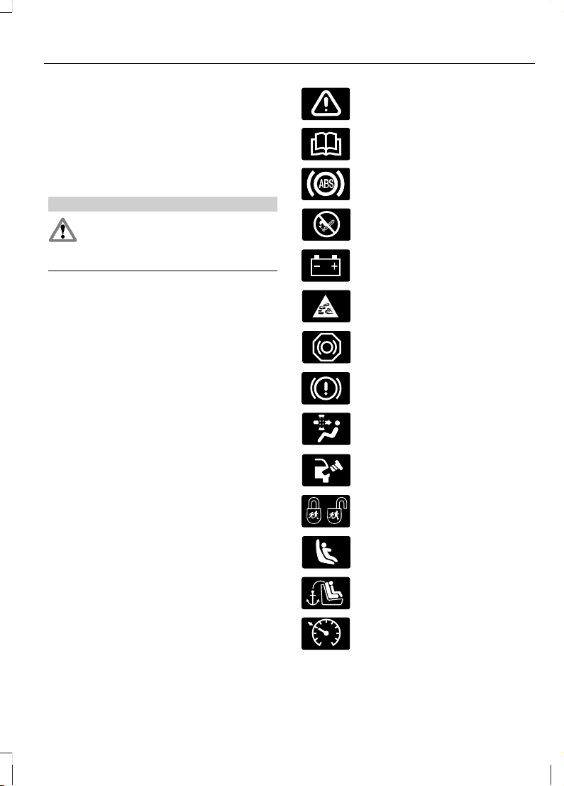
SYMBOLS GLOSSARY
These are some of the symbols you may
see on your vehicle.
Safety alert
See Owner's Manual
Anti-lock braking system
Avoid smoking, flames or sparks
Battery
Battery acid
Brake fluid - non petroleum
based
Brake system
Cabin air filter
Check fuel cap
Child safety door lock or unlock
Child seat lower anchor
Child seat tether anchor
E71340
Cruise control
7
Introduction
Page 10
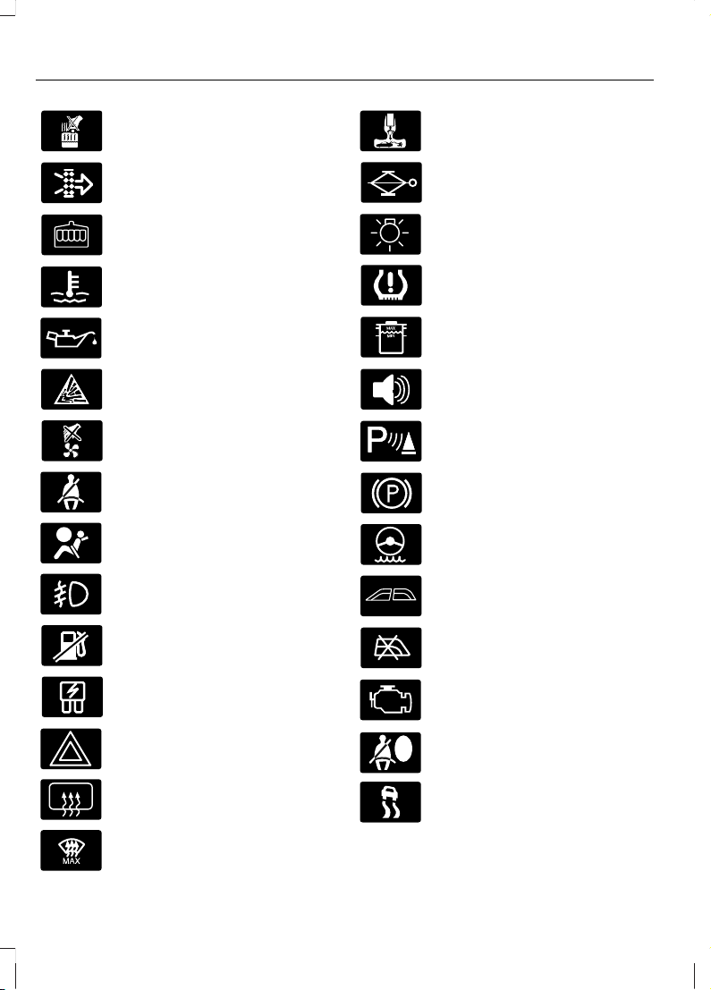
Do not open when hot
Engine air filter
Engine coolant
Engine coolant temperature
Engine oil
Explosive gas
Fan warning
Fasten safety belt
Front airbag
Front fog lamps
Fuel pump reset
Fuse compartment
Hazard warning flashers
Heated rear window
E91392
Heated windshield
Interior luggage compartment
release
Jack
Lighting control
Low tire pressure warning
Maintain correct fluid level
Panic alarm
E139213
Parking aid
Parking brake
Power steering fluid
Power windows front/rear
Power window lockout
Service engine soon
Side airbag
Stability control
8
Introduction
Page 11

Windshield wash and wipe
DATA RECORDING
Service Data Recording
Service data recorders in your vehicle are
capable of collecting and storing
diagnostic information about your vehicle.
This potentially includes information about
the performance or status of various
systems and modules in the vehicle, such
as engine, throttle, steering or brake
systems. In order to properly diagnose and
service your vehicle, Ford Motor Company,
Ford of Canada, and service and repair
facilities may access or share among them
vehicle diagnostic information received
through a direct connection to your vehicle
when diagnosing or servicing your vehicle.
Additionally, when your vehicle is in for
service or repair, Ford Motor Company,
Ford of Canada, and service and repair
facilities may access or share among them
data for vehicle improvement purposes.
For U.S. only (if equipped), if you choose
to use the SYNC Vehicle Health Report,
you consent that certain diagnostic
information may also be accessed
electronically by Ford Motor Company and
Ford authorized service facilities, and that
the diagnostic information may be used
for any purpose. See SYNC® (page 308).
Event Data Recording
This vehicle is equipped with an event
data recorder. The main purpose of an
event data recorder is to record, in
certain crash or near crash-like
situations, such as an airbag
deployment or hitting a road obstacle;
this data will assist in understanding
how a vehicle’s systems performed.
The event data recorder is designed to
record data related to vehicle dynamics
and safety systems for a short period
of time, typically 30 seconds or less.
The event data recorder in this vehicle
is designed to record such data as:
• How various systems in your vehicle
were operating;
• Whether or not the driver and
passenger safety belts were
buckled/fastened;
• How far (if at all) the driver was
depressing the accelerator and/or
the brake pedal; and
• How fast the vehicle was travelling;
and
• Where the driver was positioning
the steering wheel.
This data can help provide a better
understanding of the circumstances in
which crashes and injuries occur.
9
Introduction
Page 12

Note: Event data recorder data is
recorded by your vehicle only if a
non-trivial crash situation occurs; no data
is recorded by the event data recorder
under normal driving conditions and no
personal data or information (e.g., name,
gender, age, and crash location) is
recorded (see limitations regarding 911
Assist and Traffic, directions and
Information privacy below). However,
parties, such as law enforcement, could
combine the event data recorder data
with the type of personally identifying
data routinely acquired during a crash
investigation.
To read data recorded by an event data
recorder, special equipment is required,
and access to the vehicle or the event
data recorder is needed. In addition to
the vehicle manufacturer, other
parties, such as law enforcement, that
have such special equipment, can read
the information if they have access to
the vehicle or the event data recorder.
Ford Motor Company and Ford of
Canada do not access event data
recorder information without obtaining
consent, unless pursuant to court order
or where required by law enforcement,
other government authorities or other
third parties acting with lawful
authority. Other parties may seek to
access the information independently
of Ford Motor Company and Ford of
Canada.
Note: Including to the extent that any
law pertaining to Event Data Recorders
applies to SYNC or its features, please
note the following: Once 911 Assist (if
equipped) is enabled (set ON), 911 Assist
may, through any paired and connected
cell phone, disclose to emergency
services that the vehicle has been in a
crash involving the deployment of an
airbag or, in certain vehicles, the
activation of the fuel pump shut-off.
Certain versions or updates to 911 Assist
may also be capable of being used to
electronically or verbally provide to 911
operators the vehicle location (such as
latitude and longitude), and/or other
details about the vehicle or crash or
personal information about the
occupants to assist 911 operators to
provide the most appropriate emergency
services. If you do not want to disclose
this information, do not activate the 911
Assist feature. See SYNC® (page 308).
Additionally, when you connect to
Traffic, Directions and Information (if
equipped, U.S. only), the service uses
GPS technology and advanced vehicle
sensors to collect the vehicle’s current
location, travel direction, and speed
(“vehicle travel information”), only to
help provide you with the directions,
traffic reports, or business searches
that you request. If you do not want
Ford or its vendors to receive this
information, do not activate the
service. Ford Motor Company and the
vendors it uses to provide you with this
information do not store your vehicle
travel information. For more
information, see Traffic, Directions and
Information, Terms and Conditions.
See SYNC® (page 308).
10
Introduction
Page 13
CALIFORNIA PROPOSITION 65
WARNING
Some constituents of engine
exhaust, certain vehicle components,
certain fluids contained in vehicles
and certain products of component wear
contain or emit chemicals known to the
State of California to cause cancer and
birth defects or other reproductive harm.
PERCHLORATE
Certain components in your vehicle such
as airbag modules, safety belt
pretensioners and remote control batteries
may contain perchlorate material. Special
handling may apply for service or vehicle
end of life disposal. For more information
vist:
Web Address
www.dtsc.ca.gov/hazardouswaste/
perchlorate
FORD CREDIT
(U.S. Only)
Ford Credit offers a full range of financing
and lease plans to help you acquire your
vehicle. If you have financed or leased your
vehicle through Ford Credit, thank you for
your business.
For your convenience we offer a number
of ways to contact us, as well as help
manage your account.
Phone: 1-800-727-7000
For more information regarding Ford Credit,
as well as access Account Manager, please
go to www.fordcredit.com.
REPLACEMENT PARTS RECOMMENDATION
Your vehicle has been built to the highest
standards using quality parts. We
recommend that you demand the use of
genuine Ford and Motorcraft parts
whenever your vehicle requires scheduled
maintenance or repair. You can clearly
identify genuine Ford and Motorcraft parts
by looking for the Ford, FoMoCo or
Motorcraft branding on the parts or their
packaging.
Scheduled Maintenance and
Mechanical Repairs
One of the best ways for you to make sure
that your vehicle provides years of service
is to have it maintained in line with our
recommendations using parts that
conform to the specifications detailed in
this Owner’s Manual. Genuine Ford and
Motorcraft parts meet or exceed these
specifications.
Collision Repairs
We hope that you never experience a
collision, but accidents do happen. Genuine
Ford replacement collision parts meet our
stringent requirements for fit, finish,
structural integrity, corrosion protection
and dent resistance. During vehicle
development we validate these parts
deliver the intended level of protection as
a whole system. A great way to know for
sure you are getting this level of protection
is to use genuine Ford replacement
collision parts.
11
Introduction
Page 14
Warranty on Replacement Parts
Genuine Ford and Motorcraft replacement
parts are the only replacement parts that
benefit from a Ford Warranty. Damage
caused to your vehicle as a result of the
failure of non-Ford parts may not be
covered by the Ford Warranty. For
additional information, refer to the terms
and conditions of the Ford Warranty.
SPECIAL NOTICES
New Vehicle Limited Warranty
For a detailed description of what is
covered and what is not covered by your
vehicle’s New Vehicle Limited Warranty,
refer to the Warranty Manual that is
provided to you along with your Owner’s
Manual.
Special Instructions
For your added safety, your vehicle is fitted
with sophisticated electronic controls.
WARNINGS
Failure to follow the specific
warnings and instructions could
result in personal injury. See
Supplementary Restraints System
(page 34).
Front seat mounted rear-facing child
or infant seats should NEVER be
placed in front of an active
passenger airbag.
MOBILE COMMUNICATIONS EQUIPMENT
Using mobile communications equipment
is becoming increasingly important in the
conduct of business and personal affairs.
However, you must not compromise your
own or others’ safety when using such
equipment. Mobile communications can
enhance personal safety and security when
appropriately used, particularly in
emergency situations. Safety must be
paramount when using mobile
communications equipment to avoid
negating these benefits. Mobile
communication equipment includes, but
is not limited to, cellular phones, pagers,
portable email devices, text messaging
devices and portable two-way radios.
WARNING
Driving while distracted can result in
loss of vehicle control, accident and
injury. We strongly recommend that
you use extreme caution when using any
device or feature that may take your focus
off the road. Your primary responsibility is
the safe operation of your vehicle. We
recommend against the use of any
handheld device while driving and that you
comply with all applicable laws.
12
Introduction
Page 15

EXPORT UNIQUE OPTIONS
For your particular global region, your
vehicle may be equipped with features and
options that are different from the features
and options that are described in this
Owner’s Manual. A market unique
supplement may be supplied that
complements this book. By referring to the
market unique supplement, if provided,
you can properly identify those features,
recommendations and specifications that
are unique to your vehicle. This Owner’s
Manual is written primarily for the U.S. and
Canadian Markets. Features or equipment
listed as standard may be different on units
built for Export. Refer to this Owner’s
Manual for all other required
information and warnings.
13
Introduction
Page 16

GENERAL INFORMATION
See the following sections for directions
on how to properly use safety restraints
for children.
WARNINGS
Always make sure your child is
secured properly in a device that is
appropriate for their height, age and
weight. Child safety restraints must be
bought separately from your vehicle.
Failure to follow these instructions and
guidelines may result in an increased risk
of serious injury or death to your child.
All children are shaped differently.
The recommendations for safety
restraints are based on probable
child height, age and weight thresholds
from National Highway Traffic Safety
Administration (NHTSA) and other safety
organizations, or are the minimum
WARNINGS
requirements of law. Ford recommends
checking with a NHTSA Certified Child
Passenger Safety Technician (CPST) and
consult your pediatrician to make sure your
child seat is appropriate for your child, and
is compatible with and properly installed
in your vehicle. To locate a child seat fitting
station and CPST, contact the NHTSA toll
free at 1-888-327-4236 or on the internet
at http://www.nhtsa.dot.gov. In Canada,
check with your local St. John Ambulance
office for referral to a CPST or for further
information, contact your provincial
ministry of transportation, your local St.
John Ambulance office at
http://www.sfa.ca, or Transport Canada
at 1-800-333-0371 (http://www.tc.gc.ca).
Failure to properly restrain children in
safety seats made especially for their
height, age, and weight may result in an
increased risk of serious injury or death to
your child.
14
Child Safety
Page 17

Recommendations for Safety Restraints for Children
Recommended restraint
type
Child size, height, weight, or ageChild
Use a child safety seat
(sometimes called an
infant carrier, convertible
seat, or toddler seat).
Children weighing 40 lb (18 kg) or less
(generally age four or younger).
Infants or
toddlers
Use a belt-positioning
booster seat.
Children who have outgrown or no longer
properly fit in a child safety seat (gener-
ally children who are less than 4 ft. 9 in.
(1.45 m) tall, are greater than age four (4)
and less than age twelve (12), and
between 40 lb (18 kg) and 80 lb (36 kg)
and upward to 100 lb (45 kg) if recom-
mended by your child restraint manufac-
turer).
Small children
Use a vehicle safety belt
having the lap belt snug
and low across the hips,
shoulder belt centered
across the shoulder and
chest, and seat back
upright.
Children who have outgrown or no longer
properly fit in a belt-positioning booster
seat (generally children who are at least
4 ft. 9 in. (1.45 m) tall or greater than 80
lb (36 kg) or 100 lb (45 kg) if recom-
mended by child restraint manufacturer).
Larger children
15
Child Safety
Page 18
• You are required by law to properly use
safety seats for infants and toddlers in
the United States and Canada.
• Many states and provinces require that
small children use approved booster
seats until they reach age eight, a
height of 4 feet 9 inches (1.45 meters)
tall, or 80 pounds (36 kilograms).
Check your local and state or provincial
laws for specific requirements about
the safety of children in your vehicle.
• When possible, always properly
restrain children twelve (12) years of
age and under in a rear seating position
of your vehicle. Accident statistics
suggest that children are safer when
properly restrained in the rear seating
positions than in a front seating
position. See Front Passenger
Sensing System (page 36).
CHILD SEAT POSITIONING
WARNINGS
Airbags can kill or injure a child in a
child seat. NEVER place a rear-facing
child seat in front of an active airbag.
If you must use a forward-facing child seat
in the front seat, move your vehicle seat
all the way back. When possible, all
children age 12 and under should be
properly restrained in a rear seating
position. If all children cannot be seated
and restrained properly in a rear seating
position, properly restrain the largest child
in the front seat.
WARNINGS
Always carefully follow the
instructions and warnings provided
by the manufacturer of any child
restraint to determine if the restraint device
is appropriate for your child's size, height,
weight, or age. Follow the child restraint
manufacturer's instructions and warnings
provided for installation and use in
conjunction with the instructions and
warnings provided by your vehicle
manufacturer. A safety seat that is
improperly installed or utilized, is
inappropriate for your child's height, age,
or weight or does not properly fit the child
may increase the risk of serious injury or
death.
Never let a passenger hold a child on
his or her lap while your vehicle is
moving. The passenger cannot
protect the child from injury in a collision,
which may result in serious injury or death.
Never use pillows, books, or towels
to boost a child. They can slide
around and increase the likelihood
of injury or death in a collision.
Always restrain an unoccupied child
seat or booster seat. These objects
may become projectiles in a collision
or sudden stop, which may increase the
risk of serious injury.
Never place, or allow a child to place,
the shoulder belt under a child's arm
or behind the back because it
reduces the protection for the upper part
of the body and may increase the risk of
injury or death in a collision.
Do not leave children or pets
unattended in your vehicle.
16
Child Safety
Page 19

Use any attachment method as indicated below by XChild
Weight
Restraint
Type
Safety belt
only
Safety belt
and LATCH
(lower
anchors
and top
tether
anchor)
Safety belt
and top
tether
anchor
LATCH
(lower
anchors
only)
LATCH
(lower
anchors
and top
tether
anchor)
XXUp to 48 lb
(21 kg)
Rear facing
child seat
XXXUp to 48 lb
(21 kg)
Forward
facing
child seat
XXOver 48 lb
(21 kg)
Forward
facing
child seat
Note: The child seat must rest tightly
against your vehicle seat. It may be
necessary to lift or remove the head
restraint. See Seats (page 131).
BOOSTER SEATS
WARNING
Never place, or allow a child to place,
the shoulder belt under a child's arm
or behind the back because it
reduces the protection for the upper part
of the body and may increase the risk of
injury or death in a collision.
Use a belt-positioning booster seat for
children who have outgrown or no longer
properly fit in a child safety seat (generally
children who are less than 4 feet 9 inches
(1.45 meters) tall, are greater than age four
(4) and less than age twelve (12), and
between 40 pounds (18 kilograms) and
80 pounds (36 kilograms) and upward to
100 pounds (45 kilograms) if
recommended by your child restraint
manufacturer). Many state and provincial
laws require that children use approved
booster seats until they reach age eight, a
height of 4 feet 9 inches (1.45 meters) tall,
or 80 pounds (36 kilograms).
Booster seats should be used until you can
answer YES to ALL of these questions
when seated without a booster seat:
17
Child Safety
Page 20
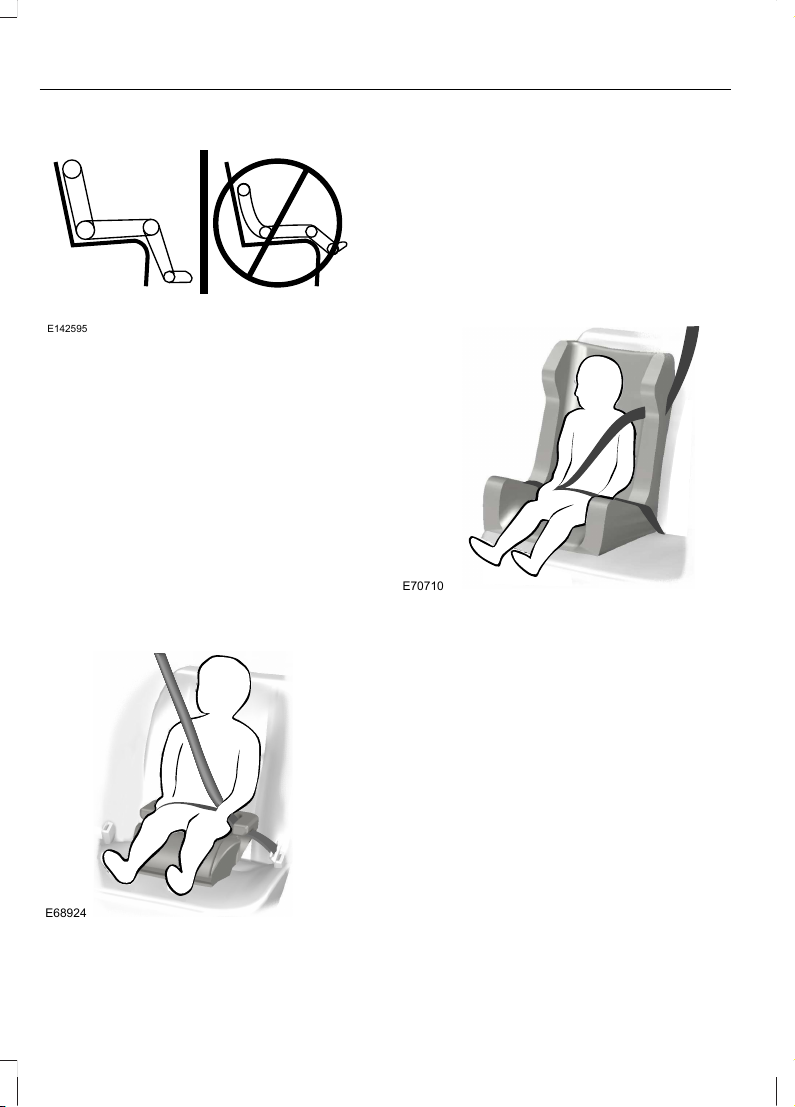
E142595
• Can the child sit all the way back
against your vehicle seat back with
knees bent comfortably at the edge of
the seat cushion?
• Can the child sit without slouching?
• Does the lap belt rest low across the
hips?
• Is the shoulder belt centered on the
shoulder and chest?
• Can the child stay seated like this for
the whole trip?
Always use booster seats in conjunction
with your vehicle lap and shoulder belt.
Types of Booster Seats
E68924
• Backless booster seats
If your backless booster seat has a
removable shield, remove the shield. If a
vehicle seating position has a low seat
back or no head restraint, a backless
booster seat may place your child's head
(as measured at the tops of the ears)
above the top of the seat. In this case,
move the backless booster to another
seating position with a higher seat back or
head restraint and lap and shoulder belts,
or consider using a high back booster seat.
E70710
• High back booster seats
If, with a backless booster seat, you cannot
find a seating position that adequately
supports your child's head, a high back
booster seat would be a better choice.
Children and booster seats vary in size and
shape. Choose a booster that keeps the
lap belt low and snug across the hips,
never up across the stomach, and lets you
adjust the shoulder belt to cross the chest
and rest snugly near the center of the
shoulder. The following drawings compare
the ideal fit (center) to a shoulder belt
uncomfortably close to the neck and a
shoulder belt that could slip off the
shoulder. The drawings also show how the
lap belt should be low and snug across the
child's hips.
18
Child Safety
Page 21
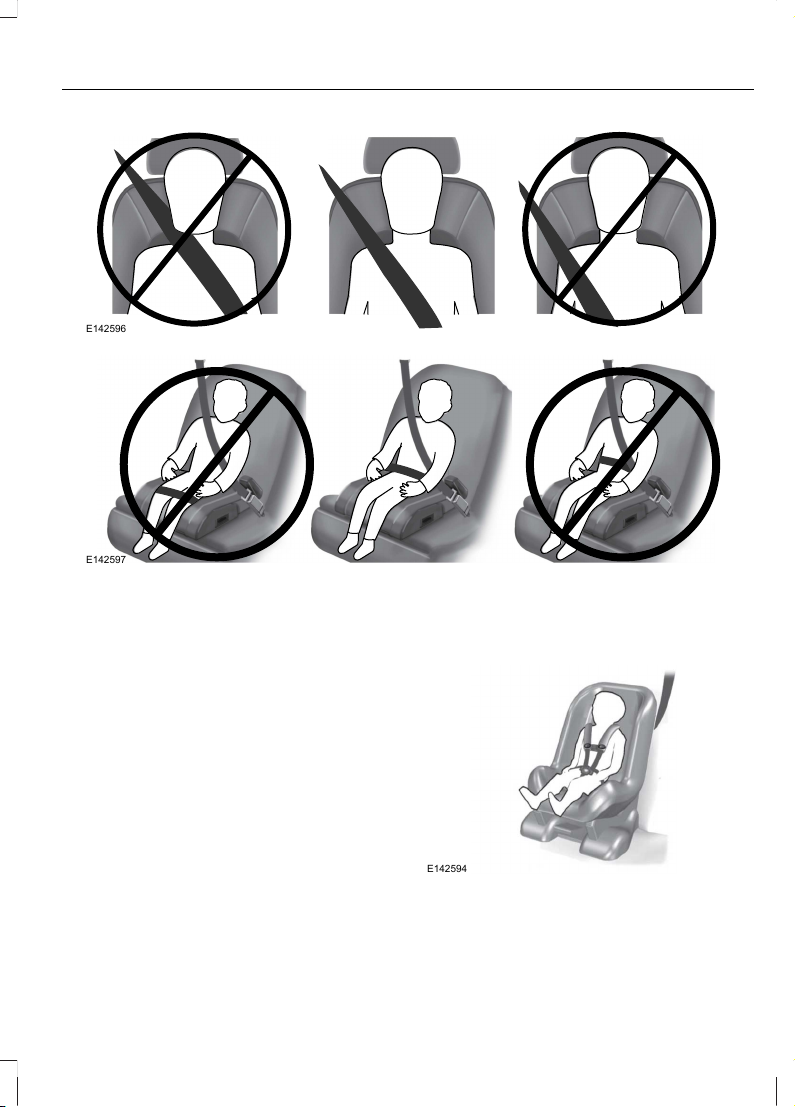
E142596
E142597
If the booster seat slides on your vehicle
seat, placing a rubberized mesh sold as
shelf or carpet liner under the booster seat
may improve this condition. Do not
introduce any item thicker than this under
the booster seat. Check with the booster
seat manufacturer's instructions.
INSTALLING CHILD SEATS
Child Seats
E142594
19
Child Safety
Page 22
Use a child safety seat (sometimes called
an infant carrier, convertible seat, or
toddler seat) for infants, toddlers, or
children weighing 40 pounds (18
kilograms) or less (generally age four or
younger).
Using Lap and Shoulder Belts
WARNINGS
Airbags can kill or injure a child in a
child seat. NEVER place a rear-facing
child seat in front of an active airbag.
If you must use a forward-facing child seat
in the front seat, move the seat all the way
back.
Children 12 and under should be
properly restrained in the rear seat
whenever possible.
Depending on where you secure a
child restraint, and depending on the
child restraint design, you may block
access to certain safety belt buckle
assemblies and LATCH lower anchors,
rendering those features potentially
unusable. To avoid risk of injury, occupants
should only use seating positions where
they are able to be properly restrained.
When installing a child safety seat with
combination lap and shoulder belts:
• Use the correct safety belt buckle for
that seating position.
• Insert the belt tongue into the proper
buckle until you hear a snap and feel it
latch. Make sure the tongue is securely
fastened in the buckle.
• Keep the buckle release button
pointing up and away from the safety
seat, with the tongue between the child
seat and the release button, to prevent
accidental unbuckling.
• Place your vehicle seat back in the
upright position.
• Put the safety belt in the automatic
locking mode. See Step 5. This vehicle
does not require the use of a locking
clip.
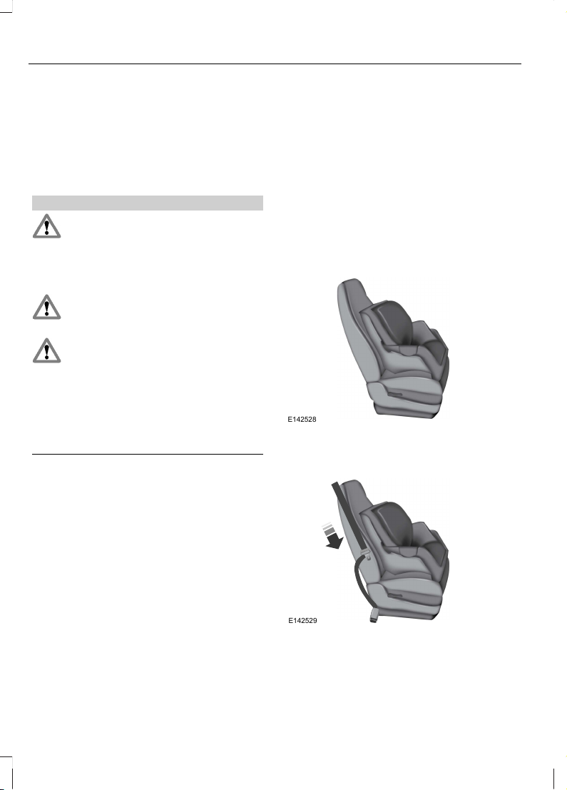
Perform the following steps when
installing the child seat with combination
lap and shoulder belts:
Note: Although the child seat illustrated is
a forward facing child seat, the steps are
the same for installing a rear facing child
seat.
E142528
1. Position the child safety seat in a seat
with a combination lap and shoulder
belt.
E142529
2. Pull down on the shoulder belt and
then grasp the shoulder belt and lap
belt together.
20
Child Safety
Page 23
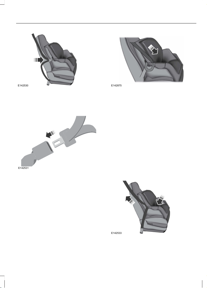
E142530
3. While holding the shoulder and lap belt
portions together, route the tongue
through the child seat according to the
child seat manufacturer's instructions.
Be sure the belt webbing is not twisted.
E142531
4. Insert the belt tongue into the proper
buckle (the buckle closest to the
direction the tongue is coming from)
for that seating position until you hear
a snap and feel the latch engage. Make
sure the tongue is latched securely by
pulling on it.
E142875
5. To put the retractor in the automatic
locking mode, grasp the shoulder
portion of the belt and pull downward
until all of the belt is pulled out.
Note: The automatic locking mode is
available on the front passenger and rear
seats. This vehicle does not require the use
of a locking clip.
6. Allow the belt to retract to remove
slack. The belt will click as it retracts
to indicate it is in the automatic locking
mode.
7. Try to pull the belt out of the retractor
to make sure the retractor is in the
automatic locking mode (you should
not be able to pull more belt out). If the
retractor is not locked, unbuckle the
belt and repeat Steps 5 and 6.
E142533
21
Child Safety
Page 24

8. Remove remaining slack from the belt.
Force the seat down with extra weight,
e.g., by pressing down or kneeling on
the child restraint while pulling up on
the shoulder belt in order to force slack
from the belt. This is necessary to
remove the remaining slack that will
exist once the extra weight of the child
is added to the child restraint. It also
helps to achieve the proper snugness
of the child seat to your vehicle.
Sometimes, a slight lean toward the
buckle will additionally help to remove
remaining slack from the belt.
9. Attach the tether strap (if the child seat
is equipped).
E142534
10. Before placing the child in the seat,
forcibly move the seat forward and
back to make sure the seat is securely
held in place. To check this, grab the
seat at the belt path and attempt to
move it side to side and forward and
back. There should be no more than
1 inch (2.5 centimeters) of movement
for proper installation.
Ford recommends checking with a NHTSA
Certified Child Passenger Safety
Technician to make certain the child
restraint is properly installed. In Canada,
check with your local St. John Ambulance
office for referral to a Certified Passenger
Seat Technician.
Using Lower Anchors and Tethers
for CHildren (LATCH)
WARNINGS
Never attach two child safety seats
to the same anchor. In a collision, one
anchor may not be strong enough to
hold two child safety seat attachments
and may break, causing serious injury or
death.
Depending on where you secure a
child restraint, and depending on the
child restraint design, you may block
access to certain safety belt buckle
assemblies or LATCH lower anchors,
rendering those features potentially
unusable. To avoid risk of injury, occupants
should only use seating positions where
they are able to be properly restrained.
The LATCH system is composed of three
vehicle anchor points: two lower anchors
located where your vehicle seat back and
seat cushion meet (called the seat bight)
and one top tether anchor located behind
that seating position.
LATCH compatible child safety seats have
two rigid or webbing mounted
attachments that connect to the two lower
anchors at the LATCH equipped seating
positions in your vehicle. This type of
attachment method eliminates the need
to use safety belts to attach the child seat,
however the safety belt can still be used
to attach the child seat. For forward-facing
child seats, the top tether strap must also
be attached to the proper top tether
anchor, if a top tether strap has been
provided with your child seat.
22
Child Safety
Page 25
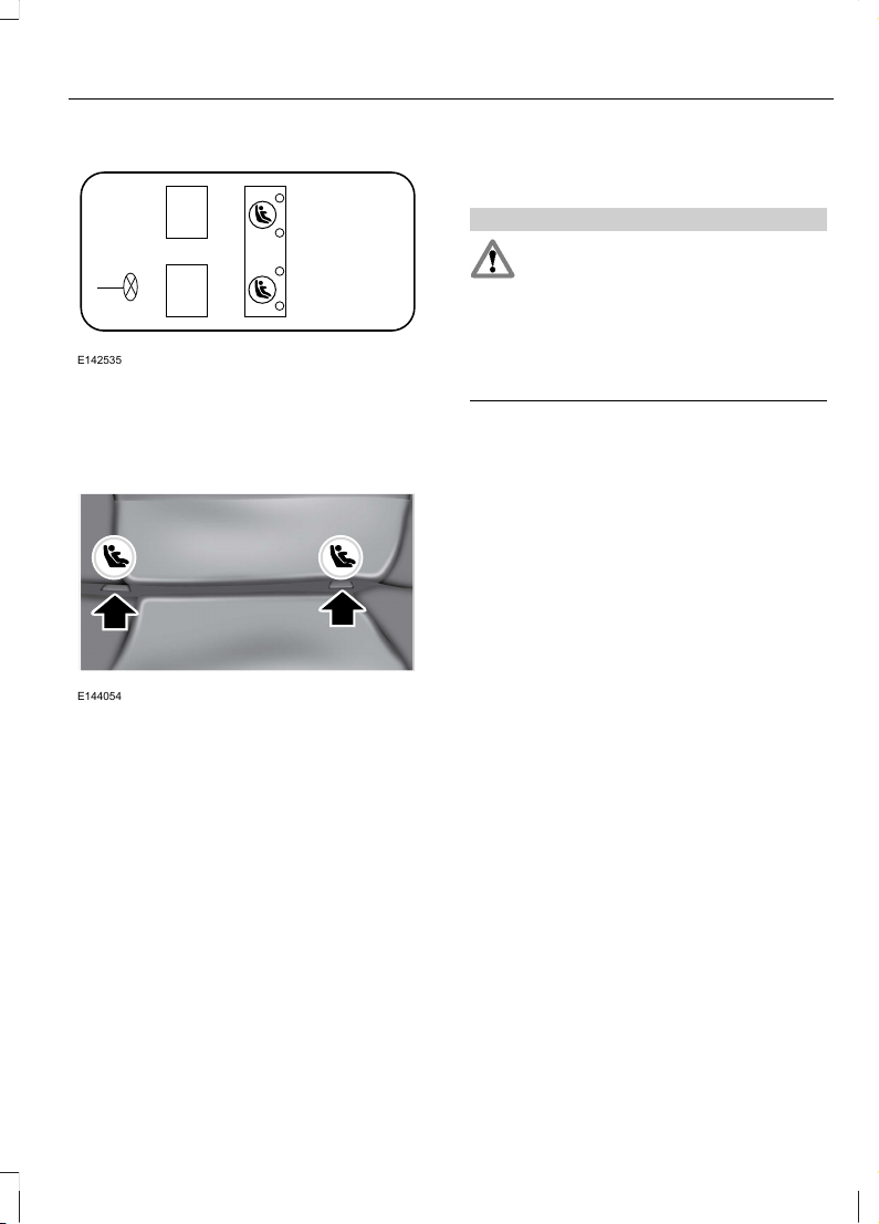
E142535
Your vehicle has LATCH lower anchors for
child seat installation at the seating
positions marked with the child seat
symbol.
E144054
The LATCH anchors are located at the rear
section of the rear seat between the
cushion and seat back below the symbols
as shown. Follow the child seat
manufacturer's instructions to properly
install a child seat with LATCH
attachments. Follow the instructions on
attaching child safety seats with tether
straps.
Attach LATCH lower attachments of the
child seat only to the anchors shown.
Use of Inboard Lower Anchors from the
Outboard Seating Positions (Center
Seating Use)
WARNING
The standardized spacing for LATCH
lower anchors is 11 inches (28
centimeters) center to center. Do not
use LATCH lower anchors for the center
seating position unless the child seat
manufacturer's instructions permit and
specify using anchors spaced at least as
far apart as those in this vehicle.
The lower anchors at the center of the
second row rear seat are spaced 18 inches
(46 centimeters) apart. A child seat with
rigid LATCH attachments cannot be
installed at the center seating position.
LATCH compatible child seats (with
attachments on belt webbing) can only be
used at this seating position provided that
the child seat manufacturer's instructions
permit use with the anchor spacing stated.
Do not attach a child seat to any lower
anchor if an adjacent child seat is attached
to that anchor.
Each time you use the safety seat, check
that the seat is properly attached to the
lower anchors and tether anchor, if
applicable. Tug the child seat from side to
side and forward and back where it is
secured to your vehicle. The seat should
move less than one inch when you do this
for a proper installation.
If the safety seat is not anchored properly,
the risk of a child being injured in a crash
greatly increases.
23
Child Safety
Page 26
Combining Safety Belt and LATCH
Lower Anchors for Attaching Child
Safety Seats
When used in combination, either the
safety belt or the LATCH lower anchors
may be attached first, provided a proper
installation is achieved. Attach the tether
strap afterward, if included with the child
seat.
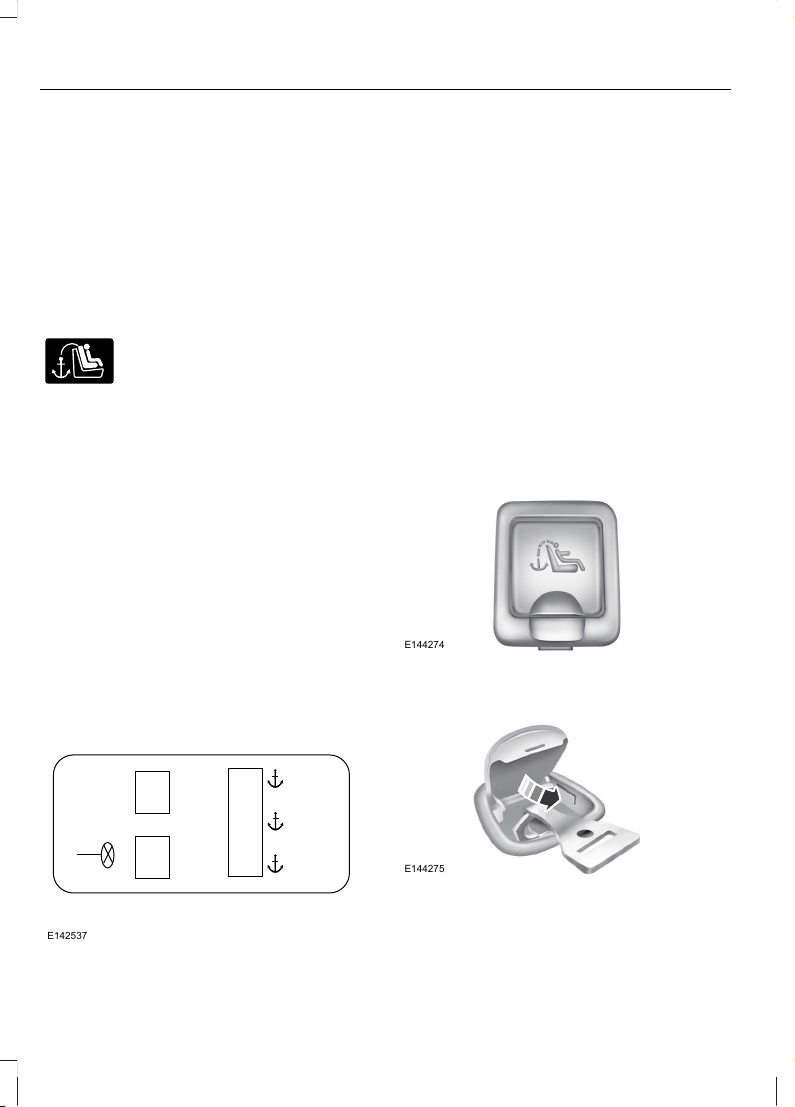
Using Tether Straps
Many forward-facing child safety
seats include a tether strap
which extends from the back of
the child safety seat and hooks to an
anchoring point called the top tether
anchor. Tether straps are available as an
accessory for many older safety seats.
Contact the manufacturer of your child
seat for information about ordering a
tether strap, or to obtain a longer tether
strap if the tether strap on your safety seat
does not reach the appropriate top tether
anchor in your vehicle.
Once the child safety seat has been
installed using either the safety belt, the
lower anchors of the LATCH system, or
both, you can attach the top tether strap.
The tether strap anchors in your vehicle
are in the following positions (shown from
top view):
E142537
Perform the following steps to install a
child safety seat with tether anchors:
Note: If you install a child seat with rigid
LATCH attachments, do not tighten the
tether strap enough to lift the child seat off
your vehicle seat cushion when the child is
seated in it. Keep the tether strap just snug
without lifting the front of the child seat.
Keeping the child seat just touching your
vehicle seat gives the best protection in a
severe crash.
1. Route the child safety seat tether strap
over the back of the seat. For outboard
seating positions, route the tether strap
under the head restraint and between
the head restraint posts. For the center
seating positions, route the tether strap
over the top of the head restraint. If
needed, the head restraints can also
be removed.
E144274
2. Locate the correct anchor for the
selected seating position, then open
the tether anchor cover.
E144275
3. Clip the tether strap to the anchor as
shown.
24
Child Safety
Page 27

4. Tighten the child safety seat tether
strap according to the manufacturer's
instructions. If your child restraint
system is equipped with a tether strap,
and the child restraint manufacturer
recommends its use, Ford also
recommends its use.
CHILD SAFETY LOCKS
When these locks are set, the rear doors
cannot be opened from the inside.
E112197
The childproof locks are located on the
rear edge of each rear door and must be
set separately for each door.
Left-Hand Side
Turn counterclockwise to lock and
clockwise to unlock.
Right-Hand Side
Turn clockwise to lock and
counterclockwise to unlock.
25
Child Safety
Page 28
PRINCIPLE OF OPERATION
WARNINGS
Always drive and ride with your
seatback upright and the lap belt
snug and low across the hips.
To reduce the risk of injury, make
sure children sit where they can be
properly restrained.
Never let a passenger hold a child on
his or her lap while the vehicle is
moving. The passenger cannot
protect the child from injury in a collision.
All occupants of the vehicle,
including the driver, should always
properly wear their safety belts, even
when an airbag supplemental restraint
system is provided.
It is extremely dangerous to ride in a
cargo area, inside or outside of a
vehicle. In a collision, people riding in
these areas are more likely to be seriously
injured or killed. Do not allow people to ride
in any area of your vehicle that is not
equipped with seats and safety belts. Be
sure everyone in your vehicle is in a seat
and using a safety belt properly.
In a rollover crash, an unbelted
person is significantly more likely to
die than a person wearing a safety
belt.
Each seating position in your vehicle
has a specific safety belt assembly
which is made up of one buckle and
one tongue that are designed to be used
as a pair. 1) Use the shoulder belt on the
outside shoulder only. Never wear the
shoulder belt under the arm. 2) Never
swing the safety belt around your neck over
the inside shoulder. 3) Never use a single
belt for more than one person.
When possible, all children 12 years
old and under should be properly
restrained in a rear seating position.
WARNINGS
Safety belts and seats can become
hot in a vehicle that has been closed
up in sunny weather; they could burn
a small child. Check seat covers and
buckles before you place a child anywhere
near them.
Front and rear seat occupants,
including pregnant women, should
wear safety belts for optimum
protection in an accident.
All seating positions in this vehicle have
lap and shoulder safety belts. All
occupants of the vehicle should always
properly wear their safety belts, even when
an airbag supplemental restraint system
is provided.
The safety belt system consists of:
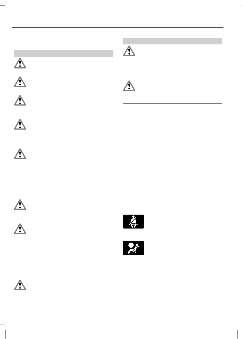
• Lap and shoulder safety belts.
• Shoulder safety belt with automatic
locking mode, (except driver safety
belt).
• Height adjuster at the front outboard
seating positions.
• Safety belt pretensioner at the front
outboard seating positions.
• Belt tension sensor at the front
outboard passenger seating position.
• Safety belt warning light and chime.
• Crash sensors and monitoring system
with readiness indicator.
26
Safety Belts
Page 29
The safety belt pretensioners at the front
seating positions are designed to tighten
the safety belts when activated. In frontal
and near-frontal collisions, the safety belt
pretensioners may be activated alone or,
if the collision is of sufficient severity,
together with the front airbags. The
pretensioners may also activate when a
side curtain airbag is deployed.
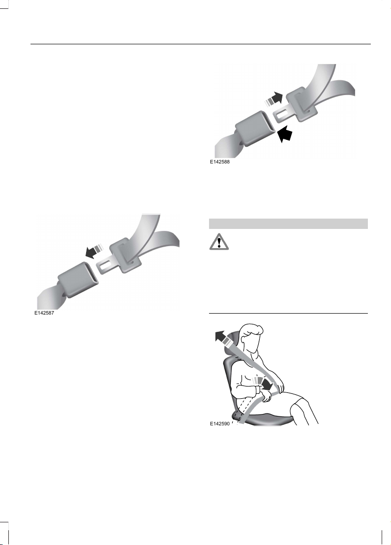
FASTENING THE SAFETY BELTS
The front outboard and rear safety
restraints in the vehicle are combination
lap and shoulder belts.
E142587
1. Insert the belt tongue into the proper
buckle (the buckle closest to the
direction the tongue is coming from)
until you hear a snap and feel it latch.
Make sure the tongue is securely
fastened in the buckle.
E142588
2. To unfasten, press the release button
and remove the tongue from the
buckle.
Restraint of Pregnant Women
WARNING
Always ride and drive with your
seatback upright and the safety belt
properly fastened. The lap portion of
the safety belt should fit snug and be
positioned low across the hips. The
shoulder portion of the safety belt should
be positioned across the chest. Pregnant
women should also follow this practice.
See the following figure.
E142590
27
Safety Belts
Page 30
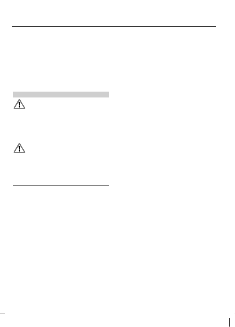
Pregnant women should always wear their
safety belt. The lap belt portion of a
combination lap and shoulder belt should
be positioned low across the hips below
the belly and worn as tight as comfort will
allow. The shoulder belt should be
positioned to cross the middle of the
shoulder and the center of the chest.
Safety Belt Locking Modes
WARNINGS
After any vehicle collision, the safety
belt system at all passenger seating
positions must be checked by an
authorized dealer to verify that the
automatic locking retractor feature for
child seats is still functioning properly. In
addition, all safety belts should be checked
for proper function.
BELT AND RETRACTOR ASSEMBLY
MUST BE REPLACED if the safety
belt assembly automatic locking
retractor feature or any other safety belt
function is not operating properly when
checked by an authorized dealer. Failure
to replace the belt and retractor assembly
could increase the risk of injury in collisions.
All safety restraints in the vehicle are
combination lap and shoulder belts. The
driver safety belt has the first type of
locking mode, and the front outboard
passenger and rear seat safety belts have
both types of locking modes described as
follows:
Vehicle Sensitive Mode
This is the normal retractor mode, which
allows free shoulder belt length
adjustment to your movements and
locking in response to vehicle movement.
For example, if the driver brakes suddenly
or turns a corner sharply, or the vehicle
receives an impact of approximately 5 mph
(8 km/h) or more, the combination safety
belts will lock to help reduce forward
movement of the driver and passengers.
In addition, the retractor is designed to lock
if the webbing is pulled out too quickly. If
this occurs, let the belt retract slightly and
pull webbing out again in a slow and
controlled manner.
Automatic Locking Mode
In this mode, the shoulder belt is
automatically pre-locked. The belt will still
retract to remove any slack in the shoulder
belt. The automatic locking mode is not
available on the driver safety belt.
When to Use the Automatic Locking
Mode
This mode should be used any time a child
safety seat, except a booster, is installed
in passenger front or rear seating positions.
Children 12 years old and under should be
properly restrained in a rear seating
position whenever possible. See Child
Safety (page 14).
28
Safety Belts
Page 31

How to Use the Automatic Locking
Mode
E142591
1. Buckle the combination lap and
shoulder belt.
2. Grasp the shoulder portion and pull
downward until the entire belt is pulled
out.
Allow the belt to retract. As the belt
retracts, you will hear a clicking sound. This
indicates the safety belt is now in the
automatic locking mode.
How to Disengage the Automatic
Locking Mode
Disconnect the combination lap and
shoulder belt and allow it to retract
completely to disengage the automatic
locking mode and activate the vehicle
sensitive (emergency) locking mode.
Safety Belt Extension Assembly
WARNING
Position the safety belt height
adjusters so that the belt rests
across the middle of your shoulder.
Failure to adjust the safety belt properly
could reduce the effectiveness of the
safety belt and increase the risk of injury in
a collision.
If the safety belt is too short when fully
extended, a safety belt extension assembly
can be obtained from an authorized dealer.
Use only extensions manufactured by the
same supplier as the safety belt.
Manufacturer identification is located at
the end of the webbing on the label. Also,
use the safety belt extension only if the
safety belt is too short for you when fully
extended.
SAFETY BELT HEIGHT ADJUSTMENT
WARNING
Position the safety belt height
adjuster so that the belt rests across
the middle of your shoulder. Failure
to adjust the safety belt properly could
reduce the effectiveness of the safety belt
and increase the risk of injury in a collision.
E145664
Adjust the height of the shoulder belt so
the belt rests across the middle of your
shoulder.
To adjust the shoulder belt height, pull the
button and slide the height adjuster up or
down. Release the button and pull down
on the height adjuster to make sure it is
locked in place.
29
Safety Belts
Page 32

SAFETY BELT WARNING LAMP AND INDICATOR CHIME
This lamp illuminates and an
audible warning will sound if the
driver's safety belt has not been
fastened when the vehicle's ignition is
turned on.
Conditions of operation
Then...If...
The safety belt warning light illuminates 1-
2 minutes and the warning chime sounds
4-8 seconds.
The driver's safety belt is not buckled
before the ignition switch is turned to the
on position...
The safety belt warning light and warning
chime turn off.
The driver's safety belt is buckled while the
indicator light is illuminated and the
warning chime is sounding...
The safety belt warning light and indicator
chime remain off.
The driver's safety belt is buckled before
the ignition switch is turned to the on posi-
tion...
SAFETY BELT MINDER
Belt-Minder®
This feature supplements the safety belt
warning function by providing additional
reminders by intermittently sounding a
chime and illuminating the safety belt
warning light when the driver's or front
passenger's seat is occupied and the
safety belt is unbuckled.
The system uses information from the
front passenger sensing system to
determine if a front seat passenger is
present and therefore potentially in need
of a warning. To avoid activating the
Belt-Minder feature for objects placed in
the front passenger seat, warnings will only
be given to front seat occupants as
determined by the front passenger sensing
system.
If the Belt-Minder warnings have expired
(warnings for approximately five minutes)
for one occupant (driver or front
passenger), the other occupant can still
activate the Belt-Minder feature.
30
Safety Belts
Page 33

Then...If...
The Belt-Minder feature will not activate.The driver's and front passenger's safety
belts are buckled before the ignition switch
is turned to the on position or less than 1-2
minutes have elapsed since the ignition
switch has been turned to on...
The Belt-Minder feature is activated - the
safety belt warning light illuminates and
the warning chime sounds for six seconds
every 25 seconds, repeating for approxim-
ately five minutes or until the safety belts
are buckled.
The driver's or front passenger's safety belt
is not buckled when the vehicle has reached
at least 6 mph (9.7 km/h) and 1-2 minutes
have elapsed since the ignition switch has
been turned to on...
The Belt-Minder feature is activated - the
safety belt warning light illuminates and
the warning chime sounds for six seconds
every 25 seconds, repeating for approxim-
ately five minutes or until the safety belts
are buckled.
The driver's or front passenger's safety belt
becomes unbuckled for approximately one
minute while the vehicle is traveling at least
6 mph (9.7 km/h) and more than 1-2
minutes have elapsed since the ignition
switch has been turned to on...
Deactivating and Activating the
Belt-Minder Feature
WARNING
While the system allows you to
deactivate it, this system is designed
to improve your chances of being
safely belted and surviving an accident.
We recommend you leave the system
activated for yourself and others who may
use the vehicle. To reduce the risk of injury,
do not deactivate or activate the system
while driving the vehicle.
Note: The driver and front passenger
warning are deactivated and activated
independently. When deactivating or
activating one seating position, do not
buckle the other position as this will
terminate the process.
Read Steps 1 - 4 thoroughly before
proceeding with the deactivation or
activation programming procedure.
The system can be deactivated or
activated by performing the following
procedure:
Before following the procedure, make sure
that:
• the parking brake is set
• the transmission selector lever is in
position P (automatic transmission)
or N (manual transmission)
• the ignition is off
• the driver and front passenger safety
belts are unbuckled.
1. Turn the ignition on. DO NOT START
THE ENGINE.
2. Wait until the safety belt warning light
turns off (approximately one minute).
After Step 2, wait an additional five
seconds before proceeding with Step
3. Once Step 3 is started, the procedure
must be completed within 60 seconds.
31
Safety Belts
Page 34

3. For the seating position being disabled,
buckle then unbuckle the safety belt
four times at a moderate speed, ending
in the unbuckled state. After Step 3,
the safety belt warning light will turn
on.
4. While the safety belt warning light is
on, buckle and then unbuckle the
safety belt. After Step 4, the safety belt
warning light will flash for confirmation.
• This will disable the feature for that
seating position if it is currently
enabled.
• This will enable the feature for that
seating position if it is currently
disabled.
CHILD RESTRAINT AND SAFETY BELT MAINTENANCE
Inspect the vehicle safety belts and child
safety seat systems periodically to make
sure they work properly and are not
damaged. Inspect the vehicle and child
seat safety belts to make sure there are no
nicks, tears or cuts. Replace if necessary.
All vehicle safety belt assemblies, including
retractors, buckles, front safety belt buckle
assemblies, buckle support assemblies
(slide bar-if equipped), shoulder belt
height adjusters (if equipped), shoulder
belt guide on seatback (if equipped), child
safety seat LATCH and tether anchors, and
attaching hardware, should be inspected
after a collision. Read the child restraint
manufacturer's instructions for additional
inspection and maintenance information
specific to the child restraint. Ford Motor
Company recommends that all safety belt
assemblies in use in vehicles involved in a
collision be replaced. However, if the
collision was minor and an authorized
dealer finds that the belts do not show
damage and continue to operate properly,
they do not need to be replaced. Safety
belt assemblies not in use during a collision
should also be inspected and replaced if
either damage or improper operation is
noted.
Properly care for safety belts. See Vehicle
Care (page 265).
32
Safety Belts
Page 35

The Personal Safety System provides an
improved overall level of frontal crash
protection to front seat occupants and is
designed to help further reduce the risk of
airbag-related injuries. The system is able
to analyze different occupant conditions
and crash severity before activating the
appropriate safety devices to help better
protect a range of occupants in a variety
of frontal crash situations.
Your vehicle's Personal Safety System
consists of:
• Driver and passenger dual-stage airbag
supplemental restraints.
• Front outboard safety belts with
pretensioners, energy management
retractors (first row only), and safety
belt usage sensors.
• Driver’s seat position sensor.
• Front passenger sensing system.
• Passenger airbag off and on indicator
lamp.
• Front crash severity sensors.
• Restraints Control Module with impact
and safing sensors.
• Restraint system warning light and
backup tone.
• The electrical wiring for the airbags,
crash sensor(s), safety belt
pretensioners, front safety belt usage
sensors, driver seat position sensor,
front passenger sensing system, and
indicator lights.
How Does the Personal Safety
System Work?
The Personal Safety System can adapt the
deployment strategy of your vehicle’s
safety devices according to crash severity
and occupant conditions. A collection of
crash and occupant sensors provides
information to the Restraints Control
Module. During a crash, the Restraints
Control Module may activate the safety
belt pretensioners and may activate either
one or both stages of the dual-stage airbag
supplemental restraints based on crash
severity and occupant conditions.
33
Personal Safety System™
Page 36

PRINCIPLE OF OPERATION
WARNINGS
Airbags DO NOT inflate slowly or
gently, and the risk of injury from a
deploying airbag is the greatest close
to the trim covering the airbag module.
All occupants of your vehicle,
including the driver, should always
properly wear their safety belts, even
when an airbag supplemental restraint
system is provided.
Always transport children 12 years
old and under in the back seat and
always properly use appropriate
child restraints.
Never place your arm over the airbag
module as a deploying airbag can
result in serious arm fractures or
other injuries.
Airbags can kill or injure a child in a
child seat. NEVER place a rear-facing
child seat in front of an active airbag.
If you must use a forward-facing child seat
in the front seat, move the seat all the way
back.
Do not attempt to service, repair, or
modify the airbag supplemental
restraint systems or its fuses.
Contact your authorized dealer as soon as
possible.
Several airbag system components
get hot after inflation. Do not touch
them after inflation.
If the airbag has deployed, the airbag
will not function again and must be
replaced immediately. If the airbag
is not replaced, the unrepaired area will
increase the risk of injury in a collision.
The airbags are a supplemental restraint
system and are designed to work with the
safety belts to help protect the driver and
right front passenger from certain upper
body injuries. Airbags DO NOT inflate
slowly; there is a risk of injury from a
deploying airbag.
Note: You will hear a loud bang and see a
cloud of harmless powdery residue if an
airbag deploys. This is normal.
The airbags inflate and deflate rapidly
upon activation. After airbag deployment,
it is normal to notice a smoke-like, powdery
residue or smell the burnt propellant. This
may consist of cornstarch, talcum powder
(to lubricate the bag) or sodium
compounds (e.g., baking soda) that result
from the combustion process that inflates
the airbag. Small amounts of sodium
hydroxide may be present which may
irritate the skin and eyes, but none of the
residue is toxic. While the system is
designed to help reduce serious injuries,
contact with a deploying airbag may also
cause abrasions or swelling. Temporary
hearing loss is also a possibility as a result
of the noise associated with a deploying
airbag. Because airbags must inflate
rapidly and with considerable force, there
is the risk of death or serious injuries such
as fractures, facial and eye injuries or
internal injuries, particularly to occupants
who are not properly restrained or are
otherwise out of position at the time of
airbag deployment. Thus, it is extremely
important that occupants be properly
restrained as far away from the airbag
module as possible while maintaining
vehicle control.
Routine maintenance of the airbags is not
required.
34
Supplementary Restraints System
Page 37

SOS POST-CRASH ALERT
SYSTEM
The system flashes the turn signal lamps
and sounds the horn (intermittently) in the
event of a serious impact that deploys an
airbag (front, side, side curtain or Safety
Canopy) or the safety belt pretensioners.
The horn and lamps will turn off when:
• the hazard control button is pressed
• the panic button (if equipped) is
pressed on the remote entry
transmitter, or
• your vehicle runs out of power.
Spin out Detection
If a spinout is detected and the hazard
warning flashers come on, the message
Spinout Detected Hazards Activated will
appear on the instrument cluster.
Once the hazard warning flashers have
been activated, they can be turned off by:
• pressing the hazard warning flasher
button.
• pressing the remote control unlock
button.
• pressing the remote control panic
button.
• cycling the ignition on and off twice.
DRIVER AND PASSENGER AIRBAGS
WARNINGS
Never place your arm or any objects
over an airbag module. Placing your
arm over a deploying airbag can
result in serious arm fractures or other
injuries. Objects placed on or over the
airbag inflation area may cause those
objects to be propelled by the airbag into
your face and torso causing serious injury.
WARNINGS
Airbags can kill or injure a child in a
child seat. Never place a rear-facing
child seat in front of an active airbag.
If you must use a forward-facing child seat
in the front seat, move the seat all the way
back.
E151127
The driver and front passenger airbags will
deploy during significant frontal and near
frontal collisions.
The driver and passenger front airbag
system consists of:
• Driver and passenger airbag modules.
• Front passenger sensing system.
· Crash sensors and monitoring
system with readiness indicator.
See Crash Sensors and Airbag
Indicator (page 41).
Proper Driver and Front Passenger
Seating Adjustment
WARNING
National Highway Traffic Safety
Administration (NHTSA)
recommends a minimum distance
of at least 10 in. (25 cm) between an
occupant’s chest and the driver airbag
module.
35
Supplementary Restraints System
Page 38

To properly position yourself away from
the airbag:
• Move your seat to the rear as far as you
can while still reaching the pedals
comfortably.
• Recline the seat slightly (one or two
degrees) from the upright position.
After all occupants have adjusted their
seats and put on safety belts, it’s very
important that they continue to sit
properly. A properly seated occupant sits
upright, leaning against the seat back, and
centered on the seat cushion, with their
feet comfortably extended on the floor.
Sitting improperly can increase the chance
of injury in a crash event. For example, if
an occupant slouches, lies down, turns
sideways, sits forward, leans forward or
sideways, or puts one or both feet up, the
chance of injury during a crash is greatly
increased.
Children and Airbags
WARNING
Airbags can kill or injure a child in a
child seat. NEVER place a rear-facing
child seat in front of an active airbag.
If you must use a forward-facing child seat
in the front seat, move the seat all the way
back.
E142846
Children must always be properly
restrained. Accident statistics suggest that
children are safer when properly restrained
in the rear seating positions than in the
front seating position. Failure to follow
these instructions may increase the risk of
injury in a collision.
KNEE AIRBAG
The driver's and passenger's knee airbags
are located under the instrument panel.
The system works along with the driver's
and passenger's front airbags to help
reduce injury to the legs. When the airbags
activate in a collision, the knee airbags
deploy from under the instrument panel.
As with front and side airbags, it is
important to be properly seated and
restrained to reduce the risk of death or
serious injury.
Make sure the knee airbags are
operating properly. See Crash
Sensors and Airbag Indicator
(page 41).
FRONT PASSENGER SENSING SYSTEM
WARNINGS
Even with Advanced Restraints
Systems, children 12 and under
should be properly restrained in a
rear seating position.
Sitting improperly out of position or
with the seat back reclined too far
can take off weight from the seat
cushion and affect the decision of the front
passenger sensing system, resulting in
serious injury or death in a crash
36
Supplementary Restraints System
Page 39

WARNINGS
To reduce the risk of possible serious
injury: Do not stow objects in seat
back map pocket (if equipped) or
hang objects off seat back if a child is in
the front passenger seat. Do not place
objects underneath the front passenger
seat or between the seat and the center
console (if equipped). Check the passenger
airbag off or pass airbag off indicator lamp
for proper airbag status. Failure to follow
these instructions may interfere with the
front passenger seat sensing system.
Any alteration or modification to the
front passenger seat may affect the
performance of the front passenger
sensing system.
This system works with sensors that are
part of the front passenger’s seat and
safety belt to detect the presence of a
properly-seated occupant and determine
if the front passenger’s frontal airbag
should be enabled (may inflate) or not.
E157152
The front passenger sensing system uses
a pass airbag off indicator which will
illuminate and stay lit to remind you that
the front passenger frontal airbag is
disabled. The indicator lamp is located at
the top center of the instrument panel.
Note: The indicator lamp will illuminate for
a short period of time when the ignition is
turned to the on position to confirm it is
functional.
The front passenger sensing system is
designed to disable (will not inflate) the
front passenger's frontal airbag when a
rear facing infant seat, a forward-facing
child restraint, or a booster seat is
detected. Even with this technology,
parents are STRONGLY encouraged to
always properly restrain children in the rear
seat. The sensor also turns off the
passenger front airbag and seat-mounted
side airbag when the passenger seat is
empty.
• When the front passenger sensing
system disables (will not inflate) the
front passenger frontal airbag, the
indicator lamp will illuminate and stay
lit to remind you that the front
passenger frontal airbag is disabled.
• If the child restraint has been installed
and the indicator lamp is not lit, then
turn the vehicle off, remove the child
restraint from the vehicle and reinstall
the restraint following the child
restraint manufacturer's instructions.
The front passenger sensing system is
designed to enable (may inflate) the front
passenger's frontal airbag anytime the
system senses that a person of adult size
is sitting properly in the front passenger
seat.
• When the front passenger sensing
system enables the front passenger
frontal airbag (may inflate), the
indicator lamp will be unlit and stay
unlit.
37
Supplementary Restraints System
Page 40

If a person of adult size is sitting in the front
passenger’s seat, but the airbag off
indicator lamp is lit, it is possible that the
person isn’t sitting properly in the seat. If
this happens:
• Turn the vehicle off and ask the person
to place the seat back in the full upright
position.
• Have the person sit upright in the seat,
centered on the seat cushion, with the
person’s legs comfortably extended.
• Restart the vehicle and have the person
remain in this position for about two
minutes. This will allow the system to
detect that person and enable the
passenger’s frontal airbag.
• If the indicator lamp remains lit even
after this, the person should be advised
to ride in the rear seat.
Passenger AirbagPassenger Airbag OFF Indic-
ator
Occupant
DisabledUnlitEmpty
DisabledLitChild
EnabledUnlitAdult
Note: When the passenger airbag off light
is illuminated, the passenger (seat
mounted) side airbag may be disabled to
avoid the risk of airbag deployment injuries.
After all occupants have adjusted their
seats and put on safety belts, it’s very
important that they continue to sit
properly. A properly seated occupant sits
upright, leaning against the seat back, and
centered on the seat cushion, with their
feet comfortably extended on the floor.
Sitting improperly can increase the chance
of injury in a crash event. For example, if
an occupant slouches, lies down, turns
sideways, sits forward, leans forward or
sideways, or puts one or both feet up, the
chance of injury during a crash is greatly
increased.
If you think that the status of the passenger
airbag off indicator lamp is incorrect, check
for the following:
• Objects lodged underneath the seat
• Objects between the seat cushion and
the center console (if equipped)
• Objects hanging off the seat back
• Objects stowed in the seatback map
pocket (if equipped)
• Objects placed on the occupant's lap
• Cargo interference with the seat
• Other passengers pushing or pulling on
the seat
• Rear passenger feet and knees resting
or pushing on the seat
The conditions listed above may cause the
weight of a properly seated occupant to
be incorrectly interpreted by the front
passenger sensing system. The person in
the front passenger seat may appear
heavier or lighter due to the conditions
described in the list above.
To know if the front passenger
sensing system is operating
properly, See Crash Sensors
and Airbag Indicator (page 41).
If the airbag readiness light is lit, do the
following:
38
Supplementary Restraints System
Page 41

The driver and adult passengers should
check for any objects that may be lodged
underneath the front passenger seat or
cargo interfering with the seat.
If objects are lodged or cargo is interfering
with the seat; please take the following
steps to remove the obstruction:
• Pull the vehicle over.
• Turn the vehicle off.
• Driver and adult passengers should
check for any objects lodged
underneath the front passenger seat
or cargo interfering with the seat.
• Remove the obstruction(s) (if found).
• Restart the vehicle.
• Wait at least two minutes and verify
that the airbag readiness light is no
longer illuminated.
• If the airbag readiness light remains
illuminated, this may or may not be a
problem due to the front passenger
sensing system.
DO NOT attempt to repair or service the
system; take your vehicle immediately to
an authorized dealer.
If it is necessary to modify an advanced
front airbag system to accommodate a
person with disabilities, contact the Ford
Customer Relationship Center. See
Getting the Services You Need (page
226).
SIDE AIRBAGS
WARNINGS
Do not place objects or mount
equipment on or near the airbag
cover, on the side of the seat backs
(of the front seats), or in front seat areas
that may come into contact with a
deploying airbag. Failure to follow these
instructions may increase the risk of
personal injury in the event of a collision.
WARNINGS
Do not use accessory seat covers.
The use of accessory seat covers
may prevent the deployment of the
side airbags and increase the risk of injury
in an accident.
Do not lean your head on the door.
The side airbag could injure you as it
deploys from the side of the
seatback.
Do not attempt to service, repair, or
modify the airbag, its fuses or the
seat cover on a seat containing an
airbag. Contact your authorized dealer as
soon as possible.
If the side airbag has deployed, the
airbag will not function again. The
side airbag system (including the
seat) must be inspected and serviced by
an authorized dealer. If the airbag is not
replaced, the unrepaired area will increase
the risk of injury in a collision.
The side airbags are located on the
outboard side of the seat backs of the front
seats. In certain lateral collisions, the
airbag on the side affected by the collision
will be inflated. The airbag was designed
to inflate between the door panel and
occupant to further enhance the protection
provided occupants in side impact
collisions.
E152533
39
Supplementary Restraints System
Page 42

The system consists of the following:
• A label or embossed side panel
indicating that side airbags are fitted
to your vehicle
• Side airbags located inside the driver
and front passenger seat backs
• Front passenger sensing system
·Crash sensors and monitoring
system with readiness indicator.
See Crash Sensors and Airbag
Indicator (page 41).
Note: The passenger sensing system will
deactivate the passenger seat-mounted
side airbag if it detects an empty, unbuckled
passenger seat.
The design and development of the side
airbag system included recommended
testing procedures that were developed
by a group of automotive safety experts
known as the Side Airbag Technical
Working Group. These recommended
testing procedures help reduce the risk of
injuries related to the deployment of side
airbags.
SIDE CURTAIN AIRBAGS
WARNINGS
Do not place objects or mount
equipment on or near the headliner
at the siderail that may come into
contact with a deploying side curtain
airbag. Failure to follow these instructions
may increase the risk of personal injury in
the event of a collision.
Do not lean your head on the door.
The side curtain airbag could injure
you as it deploys from the headliner.
Do not attempt to service, repair, or
modify the side curtain airbags, its
fuses, the A, B, or C pillar trim, or the
headliner on a vehicle containing side
curtain airbags. Contact your authorized
dealer as soon as possible.
WARNINGS
All occupants of the vehicle including
the driver should always wear their
safety belts even when an airbag
SRS and side curtain airbag is provided.
To reduce risk of injury, do not
obstruct or place objects in the
deployment path of the side curtain
airbag.
If the side curtain airbags have
deployed, the side curtain airbags
will not function again. The side
curtain airbags (including the A, B and C
pillar trim and headliner) must be
inspected and serviced by an authorized
dealer. If the side curtain airbag is not
replaced, the unrepaired area will increase
the risk of injury in a collision.
The side curtain airbags will deploy during
significant side collisions. The side curtain
airbags are mounted to the roof side-rail
sheet metal, behind the headliner, above
each row of seats. In certain lateral
collisions, the side curtain airbags on the
impacted side of the vehicle will be
activated. The side curtain airbags are
designed to inflate between the side
window area and occupants to further
enhance protection provided in side impact
collisions.
The system consists of the following:
E75004
40
Supplementary Restraints System
Page 43

• Side curtain airbags fitted above the
trim panels over the front and rear side
windows identified by a label or
wording on the headliner or roof-pillar
trim.
• A flexible headliner which opens above
the side doors to allow side air curtain
deployment.
Crash sensors and monitoring
system with readiness indicator.
See Crash Sensors and Airbag
Indicator (page 41).
Children 12 years old and under should
always be properly restrained in the back
seats. The side curtain airbags will not
interfere with children restrained using a
properly installed child or booster seat
because it is designed to inflate downward
from the headliner above the doors along
the side window opening.
The design and development of the side
curtain airbags included recommended
testing procedures that were developed
by a group of automotive safety experts
known as the Side Airbag Technical
Working Group. These recommended
testing procedures help reduce the risk of
injuries related to the deployment of side
curtain airbags.
CRASH SENSORS AND AIRBAG INDICATOR
WARNING
Modifying or adding equipment to
the front end of the vehicle (including
frame, bumper, front end body
structure and tow hooks) may affect the
performance of the airbag system,
increasing the risk of injury. Do not modify
the front end of the vehicle.
The vehicle has a collection of crash and
occupant sensors which provide
information to the Restraints Control
Module which deploys (activates) the front
safety belt pretensioners, driver airbag,
passenger airbag, knee airbag(s), seat
mounted side airbags, and the side curtain
airbags. Based on the type of collision
(frontal impact or side impact), the
restraints control module will deploy the
appropriate safety devices.
The restraints control module also
monitors the readiness of the above safety
devices plus the crash and occupant
sensors. The readiness of the safety
system is indicated by a warning indicator
light in the instrument cluster or by a
backup tone if the warning light is not
working. Routine maintenance of the
airbag is not required.
A difficulty with the system is indicated by
one or more of the following:
· The readiness light will not
illuminate immediately after the
ignition is turned on.
• The readiness light will either flash or
stay lit.
• A series of five beeps will be heard. The
tone pattern will repeat periodically
until the problem, the light or both are
repaired.
If any of these things happen, even
intermittently, have the supplemental
restraint system serviced at an authorized
dealer immediately. Unless serviced, the
system may not function properly in the
event of a collision.
The safety belt pretensioners and the front
airbag supplemental restraint system are
designed to activate when the vehicle
sustains longitudinal deceleration
sufficient to cause the restraints control
module to deploy a safety device.
41
Supplementary Restraints System
Page 44

The fact that the safety belt pretensioners
or front airbags did not activate for both
front seat occupants in a collision does not
mean that something is wrong with the
system. Rather, it means the restraints
control module determined the accident
conditions (crash severity, belt usage, etc.)
were not appropriate to activate these
safety devices.
• Front airbags are designed to activate
only in frontal and near-frontal
collisions (not rollovers, side impacts
or rear impacts) unless the collision
causes sufficient longitudinal
deceleration.
• The safety belt pretensioners are
designed to activate in frontal and
near-frontal collisions, and may also
activate when a side curtain deploys.
• A knee airbag deploys from under the
instrument panel when the front airbag
activates in a collision.
• Side airbags and side curtain airbags
are designed to inflate in side-impact
collisions, not rollovers, rear impacts,
frontal or near-frontal collisions, unless
the collision causes sufficient lateral
deceleration.
AIRBAG DISPOSAL
Contact your authorized dealer as soon as
possible. Airbags MUST BE disposed of by
qualified personnel.
42
Supplementary Restraints System
Page 45

GENERAL INFORMATION ON RADIO FREQUENCIES
This device complies with Part 15 of the
FCC Rules and with Industry Canada
license-exempt RSS standard(s).
Operation is subject to the following two
conditions: (1) This device may not cause
harmful interference, and (2) This device
must accept any interference received,
including interference that may cause
undesired operation.
Note: Changes or modifications not
expressively approved by the party
responsible for compliance could void the
user's authority to operate the equipment.
The term IC before the radio certification
number only signifies that Industry Canada
technical specifications were met.
The typical operating range for your
transmitter is approximately 33 feet (10
meters). Vehicles with the remote start
feature will have a greater range. A
decrease in operating range could be
caused by:
• weather conditions
• nearby radio towers
• structures around the vehicle
• other vehicles parked next to your
vehicle.
The radio frequency used by your remote
control can also be used by other short
distance radio transmissions (e.g. amateur
radios, medical equipment, wireless
headphones, remote controls and alarm
systems). If the frequencies are jammed,
you will not be able to use your remote
control. You can lock and unlock the doors
with the key.
Note: Make sure your vehicle is locked
before leaving it unattended.
Note: If you are in range, the remote control
will operate if you press any button
unintentionally.
Intelligent Access (If Equipped)
The system uses a radio frequency signal
to communicate with your vehicle and
authorize your vehicle to unlock when one
of the following conditions are met:
• You touch the inside of the front
exterior door handle.
• You press the luggage compartment
button.
• You press a button on the transmitter.
If excessive radio frequency interference
is present in the area or if the transmitter
battery is low, it may be necessary to
mechanically unlock your door. You can
use the mechanical key blade in your
intelligent access key to open the driver’s
door in this situation. See Remote
Control (page 43).
REMOTE CONTROL
Integrated Keyhead Transmitters
(If Equipped)
Your vehicle may be equipped with two
integrated keyhead transmitters. The key
blade is used to start the vehicle and
unlock or lock the driver’s door from
outside the vehicle. The transmitter portion
functions as the remote control.
E151797
Press the button to release the key. Press
and hold the button to fold the key back
in when not in use.
43
Keys and Remote Controls
Page 46

E151795
Note: Your vehicle’s keys were issued with
a security tag that provides important
vehicle key cut information. Keep the tag in
a safe place for future reference.
Intelligent Access Key (If Equipped)
E144506
Your vehicle may be equipped with two
intelligent access keys which operate the
power locks and the remote start system.
The key must be in the vehicle to activate
the push button start system.
Removable Key Blade
The intelligent access key also contains a
removable mechanical key blade that can
be used to unlock the driver door.
E151796
Slide the release on the back of the remote
control and pivot the cover off to access
the key blade.
E151795
Note: Your vehicle’s backup keys were
issued with a security tag that provides
important vehicle key cut information. Keep
the tag in a safe place for future reference.
Using the Key Blade
The key cylinder is hidden under a cap on
the driver's side door handle.
To remove the cap:
E151956
44
Keys and Remote Controls
Page 47

1. Insert the key blade into the slot on the
bottom of the handle and press up.
2. While maintaining upward pressure,
move the cap rearward to release it.
Gently remove the key while doing so.
To install the cap:
E151957
1. Place the cap just forward of the key
cylinder.
2. While applying pressure to the cap,
move it forward until it is in place. You
may hear a snap as it engages.
Make sure the cap is properly installed by
trying to move it rearward.
Replacing the Battery
Note: Refer to local regulations when
disposing of transmitter batteries.
Note: Do not wipe off any grease on the
battery terminals or on the back surface of
the circuit board.
Note: Replacing the battery will not delete
the transmitter from the vehicle. The
transmitter should operate normally.
A message will appear in the information
display when the remote control battery
is low. See Information Messages (page
96).
Integrated Keyhead Transmitter
The remote control uses one coin-type
three-volt lithium battery CR2032 or
equivalent.
Press the button to release the key before
beginning the procedure.
E151798
1. Insert a screwdriver in the position
shown and gently push the clip.
2. Press the clip down to release the
battery cover.
E151799
3. Carefully remove the cover.
45
Keys and Remote Controls
Page 48

Note: Do not touch the battery contacts or
the printed circuit board with the
screwdriver.
4. Insert a screwdriver as shown to
release the battery.
E151801
5. Remove the battery.
6. Install a new battery with the + facing
up.
7. Replace the battery cover.
Intelligent Access Transmitter
The remote control uses two coin-type
three-volt lithium batteries CR2025 or
equivalent.
E151796
1. Slide the release on the back of the
remote control and pivot the cover off.
E153890
2. Insert a coin into the slot and twist to
separate the housing.
E153891
3. Remove the batteries.
4. Install new batteries with the + facing
each other.
Note: Make sure to replace the label
between the two batteries.
46
Keys and Remote Controls
Page 49

5. Reinstall the housing and cover.
Car Finder
E138623
Press the button twice within
three seconds. The horn will
chirp and the turn signals will
flash. It is recommended that this method
be used to locate your vehicle, rather than
using the panic alarm.
Sounding a Panic Alarm
Note: The panic alarm will only operate
when the ignition is off.
E138624
Press the button to activate the
alarm. Press the button again or
turn the ignition on to deactivate.
Remote Start (If Equipped)
WARNING
To avoid exhaust fumes, do not use
remote start if your vehicle is parked
indoors or areas that are not well
ventilated.
Note: Do not use remote start if your vehicle
is low on fuel.
E138625
Your vehicle has remote start if
the transmitter has this button.
The remote start feature allows you to
start the vehicle from outside the vehicle.
The transmitter has an extended operating
range.
Vehicles with automatic climate control
can be configured to operate when the
vehicle is remote started. See Climate
Control (page 122). A manual climate
control system will run at the setting it was
set to when the vehicle was last turned off.
Many states and provinces have
restrictions for the use of remote start.
Check your local and state or provincial
laws for specific requirements regarding
remote start systems.
The remote start system will not work if:
• the ignition is on
• the alarm system is triggered
• the feature has been disabled
• the hood is not closed
• two remote vehicle starts have already
been attempted within the last hour
• the vehicle is not in P
• the vehicle battery voltage is too low
• the service engine soon light is on.
Remote Control Feedback
An LED on the remote control provides
status feedback of remote start or stop
commands.
StatusLED
Remote start or
extension
successful
Solid green
Remote stop
successful; engine
off
Solid red
Remote start or
stop failed
Blinking red
Waiting for status
update
Blinking green
Remote Starting the Vehicle
Note: Each button press must be done
within three seconds of each other. The
vehicle will not remote start if this sequence
is not followed and the horn will not chirp.
47
Keys and Remote Controls
Page 50

E138626
The tag with your transmitter details the
starting procedure. To remote start the
vehicle:
1. Press the lock button to lock all the
doors.
2. Press the remote start button twice.
The exterior lamps will flash twice.
The horn will chirp if the system fails to
start, unless quiet start is on. Quiet start
will run the blower fan at a slower speed
to reduce noise. It can be switched on or
off in the information display. See General
Information (page 84).
Note: If the vehicle has been remote started
and is equipped with an integrated keyhead
transmitter, you must turn the ignition on
before driving the vehicle. If equipped with
an intelligent access transmitter, you must
press the START/STOP button on the
instrument panel once while applying the
brake pedal before driving the vehicle.
The power windows will be inhibited during
the remote start and the radio will not turn
on automatically.
The parking lamps will remain on and the
engine will run for 5, 10, or 15 minutes,
depending on the setting.
Extending the Vehicle Run Time
Repeat Steps 1 and 2 with the vehicle still
running to extend the run time for another
remote start duration. If you programmed
the duration to last 10 minutes, the second
10 minutes will begin after what is left of
the first activation time. For example, if the
vehicle had been running from the first
remote start for five minutes, the vehicle
will continue to run now for a total of 15
minutes. You can only extend the remote
start once.
Wait at least five seconds before remote
starting after a vehicle shutdown. Only two
remote starts are allowed.
The ignition must be turned on and then
back off or allow one hour to pass before
using remote start again if additional
remote starts are desired.
Turning the Vehicle Off After Remote
Starting
E138625
Press the button once. The
parking lamps will turn off.
You may have to be closer to the
vehicle than when starting due to ground
reflection and the added noise of the
running vehicle.
You can disable or enable the remote start
system through the information display.
See General Information (page 84).
REPLACING A LOST KEY OR REMOTE CONTROL
Replacement or additional keys or remote
controls can be purchased from your
authorized dealer. Your dealer can program
the transmitters to your vehicle or you may
be able to program them yourself. See
Passive Anti-Theft System (page 59).
48
Keys and Remote Controls
Page 51

PRINCIPLE OF OPERATION
MyKey allows you to program keys with
restricted driving modes to promote good
driving habits. All but one of the keys
programmed to the vehicle can be
activated with these restricted modes. Any
keys that have not been programmed are
referred to as an "administrator key" or
"admin key" which can be used to:
• create a restricted key
• program optional MyKey settings
• clear all MyKey features altogether.
Once a key has been programmed you can
access the following information using the
information display control:
• How many admin keys and MyKeys are
programmed to the vehicle.
• The total distance the vehicle has been
driven with a MyKey.
For vehicles equipped with intelligent
access key (push button start), when both
a MyKey and an admin intelligent access
key (fob) are present, the admin fob will
be recognized by the vehicle to start the
engine.
Standard Settings
These settings cannot be changed.
• Belt-Minder®. This cannot be disabled
and the five-minute timer does not
expire. The audio system is muted
when MyKey Belt-Minder® is activated.
• Early low fuel. Warnings are displayed
in the information display control
followed by an audible tone when the
fuel tank is at one-eighth tank or less.
• Driver assist features, if equipped on
your vehicle, are forced on: Rear
parking aid, Blind spot information
system (BLIS®) with cross traffic alert,
Lane departure warning, Forward
collision warning system and Satellite
radio adult content restriction.
Optional Settings
These settings can be configured right after
a MyKey is first created or changed
afterward with an admin key.
• Vehicle speed limit of 65, 70, 75 and
80 mph (105, 113, 121 and 130 km/h).
Visual warnings are displayed followed
by an audible tone when vehicle speed
has reached the selected top speed.
• Vehicle speed minder of 45, 55 or 65
mph (75, 90, or 105 km/h). Visual
warnings are displayed followed by an
audible tone when the preselected
vehicle speed is exceeded.
• Audio system maximum volume of
45%. A message in the audio system
is displayed when attempting to
exceed the limited volume. Also, speed
sensitive compensated volume feature
will be disabled.
• Always on setting. When this is
selected you will not be able to disable
AdvanceTrac®, 911 Assist® or the Do
not disturb feature (if your vehicle is
equipped with these features).
CREATING A MYKEY
Use the information display control to
create a MyKey:
1. Insert the key you want to program into
the ignition or, if the vehicle is equipped
with push button start, put the
intelligent access key in the backup
slot. Backup slot information is located
in a different chapter. See Starting
and Stopping the Engine (page 145).
2. Turn the ignition on.
3. Access the main menu on the
information display controls and select
Settings, then MyKey by pressing OK
or the > button.
4. Press OK to select Create.
49
MyKey®
Page 52

5. When prompted, hold the OK button
until you see a message informing you
to label this key as a MyKey. The key
will be restricted at the next start.
The key is successfully programmed. Make
sure you label it so you can distinguish it
from the admin keys.
You can program optional settings for the
key(s). Refer to Programming/Changing
optional settings.
Programming/Changing Optional
Settings
All programmed keys can be cleared within
the same key cycle in which a key was
programmed, otherwise an admin key is
required to clear the keys. See Clearing
All MyKeys (page 50).
You can access the optional settings
through the information display control.
1. Turn the ignition on using an admin key.
2. Access the main menu and select
Settings, then MyKey.
3. Use the arrow buttons to get to an
optional feature.
4. Press OK or > to scroll through settings.
5. Press OK or > to make a selection.
CLEARING ALL MYKEYS
All programmed MyKeys can be cleared
within the same key cycle in which a MyKey
was created, otherwise an admin key is
required to clear the keys.
To clear all MyKeys (which removes all
restrictions and returns them to admin key
status), use the information display control
to do the following:
1. Access the main menu and select
Settings, then MyKey.
2. Scroll to Clear All and press the OK
button.
3. Hold the OK button until ALL MYKEYS
CLEARED is displayed.
CHECKING MYKEY SYSTEM STATUS
The information display control displays
information about keys programmed to
the vehicle:
• MYKEY MILES: Tracks mileage when
a restricted key is used. If mileage does
not accumulate as expected, then the
key is not being used by the intended
user. The only way to reset this to zero
is by clearing MyKeys. If the mileage is
lower than the last time you checked,
then the key system has been recently
reset.
• #MYKEY(S): Indicates how many
restricted keys are programmed to the
vehicle. Can also be used to detect
deletion of a restricted key.
• #ADMIN KEY(S): Indicates how
many admin keys are programmed to
the vehicle. Can also be used to detect
if an additional key has been
programmed to the vehicle.
USING MYKEY WITH REMOTE START SYSTEMS
MyKey is NOT compatible with
non-Ford-approved aftermarket remote
start systems. If you choose to install a
remote start system please see your Ford
authorized dealer for a Ford-approved
remote start system.
50
MyKey®
Page 53

MYKEY TROUBLESHOOTING
Potential CausesCondition
· The key in the ignition does not have admin
privileges.
I cannot program a key.
· The key in the ignition is the only admin
key (there always has to be at least one
admin key).
· The intelligent access key is not in the
backup slot (vehicles with push-button
start).
· SecuriLock® passive anti-theft system is
disabled or in unlimited mode.
· The key in the ignition does not have admin
privileges. I cannot program the optional
settings.
I cannot program the optional settings.
· No keys are programmed to the vehicle.
See Creating a MyKey (page 49).
· The key in the ignition does not have admin
privileges.
I cannot clear the restricted keys.
· No restricted keys are programmed to the
vehicle. See Creating a MyKey (page 49).
· Purchase a new key from your authorized
dealer.
I lost the only admin key.
· Program a spare key. See Passive Anti-
Theft System (page 59).
I lost a key.
· An admin fob is present at engine startup.
No restricted key functions with intelligent
access key (push-button start).
· No MyKey keys are programmed to the
vehicle. See Creating a MyKey (page 49).
· The MyKey key is not being used by the
intended user.
MyKey miles do not accumulate.
· The key system has been reset.
51
MyKey®
Page 54

LOCKING AND UNLOCKING
You can use the power door lock control
or the remote control to lock and unlock
the vehicle.
Power Door Locks
The power door lock control is located on
the driver and front passenger door panels.
E138628
UnlockA
LockB
Door Lock Indicator
An LED on each door window trim will light
when the door is locked. It will remain lit
for up to 10 minutes after the ignition is
switched off.
Switch Inhibitor
When you electronically lock your vehicle,
the power door lock switch will no longer
operate after 20 seconds. You must unlock
your vehicle with the remote control or
keyless keypad, or switch the ignition on,
to restore function to these switches. This
feature can be switched on or off in the
information display. See General
Information (page 84).
Rear Door Unlocking and Opening
Pull the interior door release handle twice
to unlock and open the rear door. The first
pull unlocks the door and the second pull
will unlatch the door.
Remote Control
The remote control can be used at any
time. The luggage compartment release
button will only work when the vehicle
speed is less than 5 mph (8 km/h).
Unlocking the Doors (Two-Stage
Unlock)
E138629
Press the button to unlock the
driver’s door.
Press the button again within
three seconds to unlock all doors. The turn
signals will flash.
Press and hold both the lock and unlock
buttons on the remote control for three
seconds to change between driver's door
or all doors unlock mode. The turn signals
will flash twice to indicate the unlocking
mode was changed. Driver's door unlock
mode will only unlock the driver's door
when the unlock button is pressed once.
All door unlock mode will unlock all doors
with one press of the unlock button. The
unlocking mode will be applied to the
remote control, keyless entry keypad and
intelligent access. The mode can also be
changed in the information display. See
General Information (page 84).
Locking the Doors
E138623
Press the button to lock all the
doors. The turn signals will
illuminate.
Press the button again within three
seconds to confirm that all the doors are
closed. The doors will lock again, the horn
will chirp and the turn signals will
illuminate if all the doors and the luggage
compartment are closed.
52
Locks
Page 55

Note: If any door or the luggage
compartment is not closed, or if the hood is
not closed on vehicles equipped with an
anti-theft alarm or remote start, the horn
will chirp twice and the lamps will not flash.
This feature can be enable or disabled in
the information display. See General
Information (page 84).
Opening the Luggage Compartment
E138630
Press twice within three seconds
to open the luggage
compartment.
Make sure the luggage compartment is
closed and latched before driving your
vehicle. An unlatched luggage
compartment may cause objects to fall
out or block your view.
Activating Intelligent Access (If
Equipped)
Intelligent access can be switched off with
the key free feature in the information
display. See General Information (page
84).
The intelligent access key must be within
3 feet (1 meter) of the vehicle.
At a Door
Pull an exterior door handle. The door will
unlock and can be opened.
E157085
Touch the top of the door handle to lock
the vehicle.
At the Luggage Compartment
E144402
Press the exterior release button hidden
above the license plate.
Smart Unlocks For Integrated
Keyhead Transmitter
This feature helps to prevent you from
locking yourself out of the vehicle if your
key is still in the ignition.
When you open one of the front doors and
lock the vehicle with the power door lock
control, all the doors will lock then unlock
and the horn will chirp twice if your key is
still in the ignition.
The vehicle can still be locked with the key
in the ignition by using the keyless entry
keypad with the driver door closed, or by
pressing the lock button on the transmitter
even if the doors are not closed.
If both front doors are closed, the vehicle
can be locked by any method, regardless
of whether the key is in the ignition or not.
Smart Unlocks For Intelligent
Access Keys (If Equipped)
This feature helps to prevent you from
unintentionally locking your intelligent
access key inside your vehicle’s passenger
compartment or rear cargo area.
53
Locks
Page 56

When you electronically lock your vehicle
using the driver or passenger power door
lock control (with any door open, vehicle
in park and ignition off), after you close the
last door the vehicle will search for an
intelligent access key in the passenger
compartment. If an intelligent access key
is found inside the vehicle, all of the doors
will immediately unlock and the horn will
chirp twice, indicating that the intelligent
access key is inside.
In order to override the smart unlock
feature and intentionally lock the
intelligent access key inside the vehicle,
you can lock your vehicle after all doors
are closed by using the keyless entry
keypad, pressing the lock button on
another intelligent access key or touching
the locking area on the handle with another
intelligent access key in your hand.
When you open one of the front doors and
lock the vehicle using the power door lock
control, all doors will lock then unlock if:
• the ignition is on, or
• the ignition is off and the vehicle is not
in P.
Auto Relock
If you press the unlock button on the
remote control and do not open a door
within 45 seconds, your vehicle will lock
and the alarm will arm. This feature can
be enabled or disabled in the information
display. See General Information (page
84).
Autolock Feature
The autolock feature will lock all the doors
when:
• all doors are closed,
• the ignition is on,
• you shift into any gear putting the
vehicle in motion, and
• the vehicle attains a speed greater than
12 mph (20 km/h).
The autolock feature repeats when:
• any door is opened then closed while
the ignition is on and the vehicle speed
is 9 mph (15 km/h) or lower, and
• the vehicle then attains a speed greater
than 12 mph (20 km/h).
Autounlock Feature
The autounlock feature will unlock all the
doors when:
• the ignition is on, all the doors are
closed, and the vehicle has been in
motion at a speed greater than 12 mph
(20 km/h);
• the vehicle has then come to a stop
and the ignition is turned off or to
accessory; and
• the driver door is opened within 10
minutes of the ignition being turned off
or to accessory.
Note: The doors will not autounlock if the
vehicle has been electronically locked after
the ignition is turned off and before the
driver's door is opened.
Enabling or Disabling
Note: The autolock and autounlock
features can be enabled or disabled
independently of each other.
These features can be enabled or disabled
by your authorized dealer for in the
information display. See General
Information (page 84).
Illuminated Entry
The interior lamps and select exterior
lamps will illuminate when the remote
entry system is used to unlock the doors.
54
Locks
Page 57

The illuminated entry system will turn off
the lights if:
• the ignition is on,
• the remote transmitter lock control is
pressed, or
• after 25 seconds of illumination.
The lights will not turn off if:
• they have been turned on with the
dimmer control, or
• any door is open.
Illuminated Exit
The interior lamps and select exterior
lamps will illuminate when all doors are
closed, the ignition is turned off and the
key is removed from the ignition
(integrated keyhead transmitter only).
The lamps will turn off if all the doors
remain closed and:
• 25 seconds elapse
• the key is inserted in the ignition
(integrated keyhead transmitter only)
• the START/STOP button is pressed
(intelligent access key only).
Battery Saver
If the courtesy lamps, dome lamps or
headlamps are left on, the battery saver
will shut them off 10 minutes after the
ignition has been turned off.
Accessory Mode Battery Saver for
Intelligent Access Keys (If Equipped)
If you shut off the engine and leave the
ignition in the on or accessory mode, the
ignition will shut off after 30 minutes.
Luggage Compartment
E144402
Press the release button above the license
plate. Your vehicle must be unlocked or
have an intelligent access transmitter
within 3 feet (1 meter) of the trunk.
KEYLESS ENTRY (IF EQUIPPED)
SECURICODE™ KEYLESS ENTRY
KEYPAD
The keypad is located near the driver’s
window. It is invisible until touched and
then it lights up so you can see and touch
the appropriate buttons.
Note: If you enter your entry code too fast
on the keypad, the unlock function may not
work. Re-enter your entry code more slowly.
55
Locks
Page 58

1 2
3 4
5 6
7 8
9 0
E138637
You can use the keypad to:
• lock or unlock the doors
• release the trunk
• recall memory seat and mirror
positions (if equipped)
• program and erase user codes
• arm and disarm the anti-theft alarm.
The keypad can be operated with the
factory set 5-digit entry code. The code is
located on the owner’s wallet card in the
glove box and is available from your
authorized dealer. You can also create up
to five of your own 5-digit personal entry
codes.
Programming a Personal Entry Code
To create your own personal entry code:
1. Enter the factory set code.
2. Press 1·2 on the keypad within five
seconds.
3. Enter your personal 5-digit code. Each
number must be entered within five
seconds of each other.
4. Press 1·2 on the keypad to save
personal code 1.
The doors will lock then unlock to confirm
that your personal entry code has been
programmed.
To program additional personal entry
codes, repeat Steps 1-3, then for Step 4:
• press 3·4 to save personal code 2
• press 5·6 to save personal code 3
• press 7·8 to save personal code 4
• press 9·0 to save personal code 5.
You may also program a personal entry
code through the MyFord Touch system
(if equipped). See Settings (page 357).
Tips:
• Do not set a code that uses five of the
same number.
• Do not use five numbers in sequential
order.
• The factory set code will work even if
you have set your own personal code.
Recalling Memory Positions (If
Equipped)
The programmed entry codes will recall
driver memory positions as follows:
• Entry code 1 will recall driver 1 memory
positions.
• Entry code 2 will recall driver 2 memory
positions.
• Entry code 3 will recall driver 3 memory
positions.
Note: Personal entry codes 4 and 5 will not
recall memory positions.
Erasing a Personal Code
1. Enter the factory set 5-digit code.
2. Press and release 1·2 on the keypad
within five seconds.
3. Press and hold 1·2 for two seconds.
This must be done within five seconds
of completing Step 2.
56
Locks
Page 59

All personal codes are now erased and only
the factory set 5–digit code will work.
Anti-Scan Feature
The keypad will go into an anti-scan mode
if the wrong code has been entered seven
times (35 consecutive button presses).
This mode disables the keypad for one
minute and the keypad lamp will flash.
The anti-scan feature will turn off after:
• one minute of keypad inactivity
• pressing the unlock button on the
remote control
• the ignition is switched on
• unlocking the vehicle using intelligent
access (if equipped).
Unlocking and Locking the Doors
To Unlock the Driver’s Door
Enter the factory set 5-digit code or your
personal code. Each number must be
pressed within five seconds of each other.
The interior lamps will illuminate.
Note: All doors will unlock if the all door
unlocking mode is enabled. See Locking
and Unlocking (page 52).
To Unlock All Doors
Enter the factory set code or your personal
code, then press 3·4 within five seconds.
To Lock All Doors
Press and hold 7·8 and 9·0 at the same
time (with the driver’s door closed). You
do not need to enter the keypad code first.
To Release the Trunk
Enter the factory set code or your personal
code, then press 5·6 within five seconds.
Displaying the Factory Set Code
With Integrated Keyhead Transmitters
Note: You will need to have two
programmed passive anti-theft keys for this
procedure.
To display the factory set code in the
information display:
1. Insert a key into the ignition and turn
the ignition on for a few seconds.
2. Turn the ignition off and remove the
key.
3. Insert the second key into the ignition
and turn the ignition on.
The factory set code will display for a few
seconds.
Note: The code may not display until after
any other warning messages first display.
With Intelligent Access Keys
Note: You will need to have two
programmed intelligent access keys for this
procedure.
To display the factory set code in the
information display:
1. Place the first programmed key in the
backup slot inside the center console.
2. Press the START/STOP button once
and wait a few seconds.
3. Press the START/STOP button again
and remove the key.
4. Insert the second programmed key into
the backup slot, then press the
START/STOP button.
The factory set code will appear in the
information display for a few seconds.
Note: The code may not display until after
any other warning messages first display.
57
Locks
Page 60

INTERIOR LUGGAGE COMPARTMENT RELEASE
WARNINGS
Keep vehicle doors and luggage
compartment locked and keep keys
and remote transmitters out of a
child’s reach. Unsupervised children could
lock themselves in the trunk and risk injury.
Children should be taught not to play in
vehicles.
Do not leave children, unreliable
adults, or animals unattended in the
vehicle. On hot days, the
temperature in the trunk or vehicle interior
can rise very quickly. Exposure of people
or animals to these high temperatures for
even a short time can cause death or
serious heat-related injuries, including brain
damage. Small children are particularly at
risk.
Your vehicle is equipped with a release
handle that provides a means of escape
for children and adults if they become
locked inside the luggage compartment.
Adults should familiarize themselves with
the operation and location of the release
handle.
E144403
The handle is located inside the luggage
compartment either on the luggage
compartment door (lid) or near the tail
lamps. It is composed of a material that
will glow for hours in darkness following
brief exposure to ambient light.
Pull the handle and push up on the luggage
compartment door (lid) to open from
within the luggage compartment.
58
Locks
Page 61

PASSIVE ANTI-THEFT SYSTEM
Note: The system is not compatible with
non-Ford aftermarket remote start systems.
Use of these systems may result in vehicle
starting problems and a loss of security
protection.
Note: Metallic objects, electronic devices
or a second coded key on the same key
chain may cause vehicle starting problems
if they are too close to the key when starting
the engine. Prevent these objects from
touching the coded key while starting the
engine. Switch the ignition off, move all
objects on the key chain away from the
coded key and restart the engine if a
problem occurs.
Note: Do not leave a duplicate coded key
in the vehicle. Always take your keys and
lock all doors when leaving the vehicle.
SecuriLock®
The system is an engine immobilization
system. It is designed to help prevent the
engine from being started unless a coded
key programmed to your vehicle is used.
Using the wrong key may prevent the
engine from starting. A message may
appear in the information display.
If you are unable to start the engine with a
correctly coded key, a malfunction has
happened and a message may appear in
the information display.
Automatic Arming
The vehicle is armed immediately after
switching the ignition off.
Automatic Disarming
Switching the ignition on with a coded key
disarms the vehicle.
Replacement Keys
Note: Your vehicle comes equipped with
two integrated keyhead transmitters or two
intelligent access keys.
The integrated keyhead transmitter
functions as a programmed ignition key
that operates all the locks and starts the
vehicle, as well as a remote control.
The intelligent access key functions as a
programmed key that operates the driver's
door lock and activates the intelligent
access with push button start systems, as
well as a remote control.
If your programmed transmitters or
standard SecuriLock coded keys
(integrated keyhead transmitters only) are
lost or stolen and you don’t have an extra
coded key, you will need to have your
vehicle towed to an authorized dealer. The
key codes need to be erased from your
vehicle and new coded keys will need to
be programmed.
Store an extra programmed key away from
the vehicle in a safe place to help prevent
any inconveniences. See your authorized
dealer to purchase additional spare or
replacement keys.
Programming a Spare Integrated
Keyhead Transmitter
Note: A maximum of eight coded keys can
be programmed to your vehicle. All eight
can be integrated keyhead transmitters.
You can program your own integrated
keyhead transmitter or standard
SecuriLock coded keys to your vehicle. This
procedure will program both the engine
immobilizer keycode and the remote entry
portion of the remote control to your
vehicle
Only use integrated keyhead transmitters
or standard SecuriLock keys.
59
Security
Page 62

You must have two previously
programmed coded keys and the new
unprogrammed key readily accessible. See
your authorized dealer to have the spare
key programmed if two previously
programmed coded keys are not available.
Read and understand the entire procedure
before you begin.
1. Insert the first previously programmed
coded key into the ignition.
2. Switch the ignition from off to on. Keep
the ignition on for at least three
seconds, but no more than 10 seconds.
3. Switch the ignition off and remove the
first coded key from the ignition.
4. After three seconds but within 10
seconds of switching the ignition off,
insert the second previously coded key
into the ignition.
5. Switch the ignition from off to on. Keep
the ignition on for at least three
seconds, but no more than 10 seconds.
6. Switch the ignition off and remove the
second previously programmed coded
key from the ignition.
7. After three seconds but within 10
seconds of switching the ignition off
and removing the previously
programmed coded key, insert the new
unprogrammed key into the ignition.
8. Switch the ignition from off to on. Keep
the ignition on for at least six seconds.
9. Remove the newly programmed coded
key from the ignition.
If the key has been successfully
programmed it will start the engine and
operate the remote entry system (if the
new key is an integrated keyhead
transmitter).
If it was not programmed successfully,
wait 10 seconds and repeat Steps 1 through
8. If you are still unsuccessful, take your
vehicle to your authorized dealer.
Programming a Spare Intelligent
Access Key
Note: A maximum for four intelligent
access keys can be programmed to your
vehicle.
You must have two previously
programmed intelligent access keys inside
the vehicle and the new unprogrammed
intelligent access keys readily accessible.
See your authorized dealer to have the
spare key programmed if two previously
programmed keys are not available.
Make sure that the vehicle is off before
beginning this procedure. Make sure that
all doors are closed before beginning and
that they remain closed throughout the
procedure. Perform all steps within 30
seconds of starting the sequence. Stop
and wait for at least one minute before
starting again if any steps are performed
out of sequence.
Read and understand the entire procedure
before you begin.
E147165
1. Place a programmed intelligent access
key in the backup slot in the center
console.
2. Wait 5 seconds, then press the
START/STOP button.
3. Remove the intelligent access key.
60
Security
Page 63

4. Within 10 seconds, place a second
programmed intelligent access key in
the backup slot and press the
START/STOP button.
5. Wait 5 seconds, then press the
START/STOP button again.
6. Remove the intelligent access key.
7. Wait 5 seconds, then place the
unprogrammed intelligent access key
in the backup slot and press the
START/STOP button.
The intelligent access key is now
programmed. Verify the remote control
functions operate and the vehicle starts
with the new intelligent access key.
If it was not programmed successfully,
wait 10 seconds and repeat Steps 1 through
7. If you are still unsuccessful, take your
vehicle to your authorized dealer.
ANTI-THEFT ALARM
The system will warn you of an
unauthorized entry to your vehicle. It will
be triggered if any door, the luggage
compartment or the hood is opened
without using the key, remote control or
keyless entry keypad.
The direction indicators will flash and the
horn will sound if unauthorized entry is
attempted while the alarm is armed.
Take all remote controls to an authorized
dealer if there is any potential alarm
problem with your vehicle.
Arming the Alarm
The alarm is ready to arm when there is
not a key in the ignition. Electronically lock
the vehicle to arm the alarm.
Disarming the Alarm
Disarm the alarm by any of the following
actions:
• Unlock the doors or luggage
compartment with the remote control
or keyless entry keypad.
• Switch the ignition on or start the
vehicle.
• Use a key in the driver’s door to unlock
the vehicle, then switch the ignition on
within 12 seconds.
Note: Pressing the panic button on the
remote control will stop the horn and signal
indicators, but will not disarm the system.
61
Security
Page 64

ADJUSTING THE STEERING WHEEL
WARNING
Do not adjust the steering wheel
when your vehicle is moving.
Note: Make sure that you are sitting in the
correct position. See Sitting in the Correct
Position (page 131).
2
2
1
E157083
1. Unlock the steering column.
2. Adjust the steering wheel to the desired
position.
E157084
3. Lock the steering column.
AUDIO CONTROL (IF EQUIPPED)
You can operate the following functions
with the control:
E144503
Volume upA
Volume downB
MuteC
MediaD
Seek down or previousE
Seek up or nextF
MEDIA
Press repeatedly to scroll through available
audio sources.
Seek, Next or Previous
Press the seek button to:
• tune the radio to the next or previous
stored preset
• play the next or the previous track.
Press and hold the seek button to:
• tune the radio to the next station up or
down the frequency band
• seek through a track.
62
Steering Wheel
Page 65

VOICE CONTROL (IF EQUIPPED)
B
A
C
E144504
End a callA
Answer a callB
Voice recognitionC
See SYNC® (page 308). See MyFord
Touch® (page 345).
CRUISE CONTROL
Type 1
E144500
Type 2
E144501
See Cruise Control (page 193).
INFORMATION DISPLAY CONTROL
E144636
See Information Displays (page 84).
63
Steering Wheel
Page 66

Cluster Display Control Features
E144811
If equipped with:
MyFord® system: This control functions
the same as the center control on the
faceplate. See Audio unit (page 111).
MyFord Touch®: Use this control to
adjust the right side of the cluster display.
Navigate through the screen and press OK
to select. See MyFord Touch® (page 345).
64
Steering Wheel
Page 67

WINDSHIELD WIPERS
Note: Fully defrost the windshield before
switching on the windshield wipers.
Note: Make sure the windshield wipers are
switched off before entering a car wash.
Note: Clean the windshield and wiper
blades if they begin to leave streaks or
smears. If that doesn't resolve the issue,
install new wiper blades.
Note: Do not operate the wipers on a dry
windshield. This may scratch the glass,
damage the wiper blades or cause the wiper
motor to burn out. Always use the
windshield washers before wiping a dry
windshield.
E144495
Single wipeA
Intermittent wipeB
Normal wipeC
High speed wipeD
Intermittent Wipe
E144496
Shortest wipe intervalA
Intermittent wipeB
Longest wipe intervalC
Use the rotary control to adjust the
intermittent wipe interval.
Speed Dependent Wipers
When your vehicle speed increases, the
interval between wipes will decrease.
AUTOWIPERS (IF EQUIPPED)
Note: Fully defrost the windshield before
switching on the windshield wipers.
Note: Make sure the windshield wipers are
switched off before entering a car wash.
Note: Clean the windshield and wiper
blades if they begin to leave streaks or
smears. If that doesn't resolve the issue,
install new wiper blades.
Note: If you switch autolamps on in
conjunction with autowipers, your low beam
headlamps will illuminate automatically
when the rain sensor activates the
windshield wipers continuously.
Note: Wet road conditions can cause
unexpected wiping or smearing.
65
Wipers and Washers
Page 68

To reduce smearing we recommend the
following:
• Lower the sensitivity of the autowipers.
• Switch to normal or high speed wipe.
• Switch the autowipers off.
E144497
Highest sensitivityA
OnB
Lowest sensitivityC
The wipers will function when moisture is
detected on the windshield. The rain
sensor will continue to monitor the amount
of moisture on the windshield and adjust
the speed of the wipers automatically. This
feature can be switched on or off in the
information display. See General
Information (page 84).
Use the rotary control to adjust the
sensitivity of the rain sensor. With low
sensitivity, the wipers will operate when
the sensor detects a large amount of
moisture on the windshield. With high
sensitivity, the wipers will operate when
the sensor detects a small amount of
moisture on the windshield.
Keep the outside of the windshield clean.
Sensor performance will be affected if the
area around the interior mirror is dirty. The
rain sensor is very sensitive and the wipers
may operate if dirt, mist or flies hit the
windshield.
WINDSHIELD WASHERS
Note: Do not operate the washers when
the washer reservoir is empty. This may
cause the washer pump to overheat.
E144498
The washers will spray for as long as you
pull the lever toward you. When you
release the lever, the wipers will operate
for a short time.
A wipe will occur a few seconds after
washing to clear any remaining washer
fluid. This feature can be switched on or
off in the information display. See General
Information (page 84).
66
Wipers and Washers
Page 69

LIGHTING CONTROL
E142449
OffA
Parking lamps, instrument panel
lamps, license plate lamps and
tail lamps
B
HeadlampsC
High Beams
E130140
Push the lever forward to switch the high
beams on.
Push the lever forward again or pull the
lever toward you to switch the high beams
off.
Headlamp Flasher
E142450
Pull the lever toward you slightly and
release it to flash the headlamps.
AUTOLAMPS (IF EQUIPPED)
Note: It may be necessary to switch your
headlamps on manually in severe weather
conditions.
E142451
The headlamps will switch on and off
automatically in low light situations or
during inclement weather.
The headlamps will remain on for a period
of time after you switch the ignition off.
You can adjust the time delay using the
information display controls. See
Information Displays (page 84).
67
Lighting
Page 70

Note: If you switch autolamps on in
conjunction with autowipers, low beam
headlamps will illuminate automatically
when the rain sensor activates the
windshield wipers continuously.
INSTRUMENT LIGHTING DIMMER
Note: If you disconnect the battery or it
becomes discharged, the illuminated
components will switch to the maximum
setting.
Vehicles With Front Fog Lamps
E132712
Press repeatedly or press and hold until
the desired level is reached.
Vehicles Without Front Fog Lamps
A B
A
E142452
Press repeatedly or press and
hold to dim.
A
Press repeatedly or press and
hold to brighten.
B
HEADLAMP EXIT DELAY
After you switch the ignition off, you can
switch the headlamps on by pulling the
direction indicator lever toward you. You
will hear a short tone. The headlamps will
switch off automatically after three
minutes with any door open or 30 seconds
after the last door has been closed. You
can cancel this feature by pulling the
direction indicator toward you again or
switching the ignition on.
DAYTIME RUNNING LAMPS (IF
EQUIPPED)
WARNING
Always remember to switch your
headlamps on in low light situations
or during inclement weather. The
system does not activate the tail lamps
and may not provide adequate lighting
during these conditions. Failure to activate
your headlamps under these conditions
may result in a collision.
68
Lighting
Page 71

The system switches the low beam
headlamps on at a reduced intensity in
daylight conditions.
To switch the system on, switch the
ignition on, and switch the lighting control
to the off, autolamp or parking lamp
position.
AUTOMATIC HIGH BEAM CONTROL (IF EQUIPPED)
The system will automatically turn on your
high beams if it is dark enough and no other
traffic is present. When it detects an
approaching vehicle’s headlights, a
preceding vehicle’s tail lamps or street
lighting, the system will turn off the high
beams before they distract other drivers.
The low beams remain on.
Note: If it appears that automatic control
of the high beams is not functioning
properly, check the windshield in front of
the camera for blockage. A clear view of the
road is required for proper system operation.
Any windshield damage in the area of the
camera field-of-view should be repaired.
Note: If a blockage is detected (e.g. bird
dropping, bug splatter, snow, or ice) and no
changes are observed, the system will go
into low beam mode until the blockage is
cleared. A message may also appear in the
instrument cluster display noting the front
camera is blocked.
Note: Typical road dust, dirt and water
spots will not affect the automatic high
beam system’s performance. However, in
cold or inclement weather conditions, the
automatic high beam system's availability
may be decreased. If the driver wants to
change the beam state independently of
the system, the driver may turn the high
beams ON or OFF using the multifunction
switch lever. Automatic control will resume
when conditions are correct.
Note: Modification of the vehicle ride height
(e.g. using much larger tires) may degrade
feature performance.
A camera sensor is centrally mounted
behind the windscreen of the vehicle, and
monitors conditions continuously to decide
when to switch the high beams off and on.
Once the system is active the high beams
will switch on if:
• The ambient light level is low enough
that high beams are needed.
• There is no traffic in front of the vehicle.
• The vehicle speed is greater than
25 mph (40 km/h).
The high beams will switch off if:
• An approaching vehicle's headlights or
a preceding vehicle's tail lamps are
detected.
• Vehicle speed falls below 16 mph
(25 km/h).
• The ambient light level is high enough
that high beams are not required.
• Severe rain, snow, or fog is detected.
• The camera is blocked.
Activating the system
Switch on the system using the information
display and autolamps. See Information
Displays (page 84). See Autolamps
(page 67).
E142451
69
Lighting
Page 72

Turn the lighting control to the autolamps
position.
Manually overriding the system
E130140
Use the lever to switch between the high
beams and the low beams.
Note: This is a temporary override and the
system will return to automatic operation
after a short period.
To permanently deactivate the system,
use the information display menu or turn
the lighting control switch from autolamps
to headlamps.
FRONT FOG LAMPS (IF EQUIPPED)
E142453
Press the control to switch the fog lamps
on or off.
You can switch the fog lamps on when the
lighting control is in any position except off
and the high beams are not on.
DIRECTION INDICATORS
E145595
Push the lever up or down to use the
direction indicators.
Note: Tap the lever up or down to make the
direction indicators flash three times to
indicate a lane change.
INTERIOR LAMPS
The lamps will switch on when one of the
following conditions have been met:
• You open any door.
• You press a remote control button.
• You touch switch A on the front interior
lamp.
Front Interior Lamp
Note: The front interior lamp switches are
on the overhead console. The exact location
of each switch on the overhead console
depends upon which roof, sunroof, and
window shade features are equipped on the
vehicle.
70
Lighting
Page 73

Note: Touch switch C to switch the door
function off when you open any door. The
indicator lamp will illuminate amber when
the door function is off. When the door
function is off and you open a door, the
courtesy and door lamps will stay off. Touch
switch C again to switch the door function
back on. The indicator lamp will illuminate
blue when the door function is on. When the
door function is on and you open a door, the
courtesy and door lamps will switch on.
E146410
All lamps on switchA
All lamps off switchB
Door function switchC
You can switch individual map lamps on
independently by touching a map lens.
Rear Interior Lamp (If Equipped)
A
E142455
You can switch individual dome lamps on
independently by pressing switch A.
71
Lighting
Page 74

POWER WINDOWS
WARNINGS
Do not leave children unattended in
your vehicle and do not let them play
with the power windows. They may
seriously injure themselves.
When closing the power windows,
you should verify they are free of
obstructions and make sure that
children and pets are not in the proximity
of the window openings.
Note: During low battery conditions and
engine re-cranking, window operation may
be delayed or stop until after the engine
starts.
E146043
Note: You may hear a rumbling noise when
just one of the windows are open. Lower the
opposite window slightly to reduce this
noise.
Press the switch to open the window.
Lift the switch to close the window.
One-Touch Down
Press the switch fully and release it. Press
or lift it again to stop the window.
One-Touch Up
Lift the switch fully and release it. Press or
lift it again to stop the window.
Bounce-Back
The window will stop automatically while
closing. It will reverse some distance if
there is an obstacle in the way.
Overriding the Bounce-Back Feature
Pull up the window switch and hold within
two seconds of the window reaching the
bounce-back position. The window will
travel up with no bounce-back protection.
The window will stop if the switch is
released before the window is fully closed.
Global Opening and Closing
Note: The ignition must be off and the
accessory delay feature must not be
activated in order for this feature to operate.
Note: This feature can be disabled or
enabled by your authorized dealer or in the
information display. See General
Information (page 84).
You can open and close your vehicle's
windows, and vent the moonroof (if
equipped) using the remote control.
Opening the Windows
Press and hold the unlock button on the
remote control to begin opening the
windows and venting the moonroof (if
equipped).
Press the lock or unlock button on the
remote control to stop motion.
Closing the Windows
WARNING
Before operating power windows
and moonroof, you should verify that
they are free of obstructions and
make sure that children and pets are not
in the proximity of window openings.
72
Windows and Mirrors
Page 75

Press and hold the lock button on the
remote control to begin closing the
windows and moonroof (if equipped).
Press the lock or unlock button on the
remote control to stop motion.
Window Lock
E144072
Press the control to lock or unlock the rear
window controls. It will illuminate when
the rear window controls are locked.
Accessory Delay
You can use the window switches for
several minutes after you have switched
the ignition off or until either front door is
opened.
EXTERIOR MIRRORS
Power Exterior Mirrors
WARNING
Do not adjust the mirrors when your
vehicle is moving.
E144073
Left-hand mirrorA
Adjustment controlB
Right-hand mirrorC
To adjust a mirror:
1. Select the mirror you want to adjust.
The control will illuminate.
2. Adjust the position of the mirror.
3. Press the mirror switch again.
Fold-Away Exterior Mirrors
Push the mirror toward the door window
glass. Make sure that you fully engage the
mirror in its support when returning it to its
original position.
Heated Exterior Mirrors (If Equipped)
See Heated Windows and Mirrors (page
128).
Memory Mirrors (If Equipped)
You can save and recall the mirror
positions through the memory function.
See Memory Function (page 134).
Auto-Dimming Feature (If Equipped)
The driver’s exterior mirror will
automatically dim when the interior
auto-dimming mirror is activated.
73
Windows and Mirrors
Page 76

Signal Indicator Mirrors (If Equipped)
The outer portion of the appropriate mirror
housing will blink when the turn signal is
activated.
Integrated Blind Spot Mirrors (If
Equipped)
WARNING
Objects in the blind spot mirror are
closer than they appear.
Blind spot mirrors have an integrated
convex mirror built into the upper outboard
corner of the exterior mirrors. They are
designed to increase your visibility along
the side of your vehicle.
Check the main mirror first before a lane
change, then check the blind spot mirror.
If no vehicles are present in the blind spot
mirror and the traffic in the adjacent lane
is at a safe distance, signal that you intend
to change lanes. Glance over your shoulder
to verify traffic is clear and carefully
change lanes.
A
B
C
E138665
The image of the approaching vehicle is
small and near the inboard edge of the
main mirror when it is at a distance. The
image becomes larger and begins to move
outboard across the main mirror as the
vehicle approaches (A). The image will
transition from the main mirror and begin
to appear in the blind spot mirror as the
vehicle approaches (B). The vehicle will
transition to your peripheral field of view
as it leaves the blind spot mirror (C).
Blind Spot Monitor (If Equipped)
See Blind Spot Monitor (page 207).
INTERIOR MIRROR
WARNING
Do not adjust the mirror when your
vehicle is moving.
74
Windows and Mirrors
Page 77

Note: Do not clean the housing or glass of
any mirror with harsh abrasives, fuel or other
petroleum or ammonia-based cleaning
products.
You can adjust the interior mirror to your
preference. Some mirrors also have a
second pivot point. This lets you move the
mirror head up or down and from side to
side.
Pull the tab below the mirror toward you
to reduce glare at night.
Auto-Dimming Mirror (If Equipped)
Note: Do not block the sensors on the front
and back of the mirror. Mirror performance
may be affected. A rear center passenger or
raised rear center head restraint may also
block light from reaching the sensor.
The mirror will dim automatically to reduce
glare when bright lights are detected from
behind your vehicle. It will automatically
return to normal reflection when you select
reverse gear to make sure you have a clear
view when backing up.
SUN VISORS
E138666
Rotate the sun visor toward the side
window and extend it rearward for extra
shade.
Illuminated Vanity Mirror
E138667
Lift the cover to switch the lamp on.
MOONROOF (IF EQUIPPED)
WARNINGS
Do not let children play with the
moonroof or leave them unattended
in the vehicle. They may seriously
hurt themselves.
When closing the moonroof, you
should verify that it is free of
obstructions and make sure that
children and pets are not in the proximity
of the roof opening.
The sliding shade can be manually opened
or closed when the moonroof is closed.
Pull the shade toward the front of the
vehicle to close it.
The moonroof controls are located on the
overhead console and have a one-touch
open and close feature. To stop it during
one-touch operation, touch the control a
second time.
75
Windows and Mirrors
Page 78

E144499
OpenA
VentB
CloseC
Opening and Closing the Moonroof
Touch (A) to open the moonroof. It will
stop short of the fully opened position.
Note: This position helps to reduce wind
noise or rumbling which may happen with
the moonroof fully open. Touch (A) again
to fully open the moonroof.
Touch (C) to close the moonroof.
Bounce-Back
The moonroof will stop automatically and
reverse some distance if an obstacle is
detected while closing.
Touch and hold (C) within two seconds of
a bounce-back event to override this
function.
Venting the Moonroof
Touch (B) to vent the moonroof. Touch
(C) to close it.
76
Windows and Mirrors
Page 79

GAUGES
E151261
Left Information DisplayA
SpeedometerB
Right Information Display See General Information (page 345).C
Left Information Display
Odometer
Located in the bottom of the information
display Registers the accumulated
distance your vehicle has traveled.
Trip Computer
See General Information (page 84).
Vehicle Settings and Personalization
See General Information (page 84).
Common Displays
Note: Battery gauge information can be
individually selected on or off through
Battery Display in the Options sub-menu.
From any main display a right arrow press
on the steering wheel controls will take you
to the Options sub-menu.
77
Instrument Cluster
Page 80

Note: For Energi vehicles there are two
versions of the battery gauge. When the
vehicle is in Hybrid Mode the information is
shown with a simple battery graphic. When
in Plug-in Power Mode an enhanced battery
graphic is provided and available electric
range is added to the display.
Battery Gauge:
The high voltage battery gauge appears
on the right side of the information display
screen. This provides Charge Fill (State of
Charge), Charge Assist and Regen Display.
• Charge Fill (Hybrid Mode) - The fill
level, or State of Charge indicates the
amount of energy stored in the high
voltage battery as a percent of total
energy capacity. The level will increase
or decrease as the battery charges and
discharges during normal operation,
but the hybrid system will attempt to
control the level to approximately the
middle of the gauge under most driving
conditions.
• Charge Fill (Energi Plug-in Power
Mode) - The fill level indicates the
amount of energy stored in the high
voltage battery which is available for
Plug-in Power Mode. A full fill
represents the total amount of energy
you can get from an external charge
(plugging your vehicle in). When the fill
reaches empty your vehicle will
automatically enter Hybrid Mode.
• Electric Range (Energi Plug-in Power
Mode) - The electric range estimate is
based on the amount of battery energy
currently available in the high voltage
battery and your typical energy usage
while driving. This includes your drive
habits as well as your use of
accessories such as Climate Control.
The battery energy refers to the energy
gained from charging the battery while
plugged in.
• Charge Assist - The up and down
arrows provide information about the
energy going into and out of the high
voltage battery. The up arrow above
the battery indicates battery charging
such as from regenerative braking. The
down arrow below the battery
indicates battery discharging to provide
power for propulsion or vehicle
accessories.
Note: The Charge Fill is always shown for
Plug-in Power Mode, even if Charge Fill is
not selected under Battery Display in the
Options sub-menu.
• Regen Display - A circular arrow
symbol appears in the center of the
Battery Gauge when energy is being
recaptured through the regenerative
braking system.
Fuel Gauge:
The fuel gauge will indicate approximately
how much fuel is left in the fuel tank. The
fuel gauge may vary slightly when your
vehicle is moving or on a gradient. The
arrow adjacent to the fuel pump symbol
indicates on which side of the vehicle the
fuel filler door is located.
78
Instrument Cluster
Page 81

Brake Coach Display:
The Brake Coach appears after the vehicle
has come to a stop. It coaches you to brake
in a manner which maximizes the amount
of energy returned through the
regenerative braking system. The percent
displayed is an indication of the
regenerative braking efficiency with 100%
representing the maximum amount of
energy recovery.
Trip Summary and Lifetime Summary:
These will be displayed upon shutting off
the vehicle. Trip Summary will appear first,
then Lifetime Summary will be displayed.
You can toggle between these displays
using the up and down arrow keys on the
left hand steering wheel controls.
Trip Summary data is from the last power
cycle, while Lifetime Summary data is
cumulative from the last Lifetime
Summary reset done through the Settings
menu in the message center.
Trip Summary:
• Distance - The total distance traveled,
distance traveled on battery power
only (EV distance) and Regen distance
are displayed. Regen distance is the
estimated range gained from energy
recaptured through regenerative
braking.
• Energy Use - The average fuel economy
and total fuel used are displayed. In
addition for Energi, the total electrical
energy used while in Plug-in Power
Mode is displayed in kilowatt hours
(kWh). Trip Summary average fuel
economy will be shown in blue if better
than your lifetime average fuel
economy
• Brake Score - The average percentage
of braking energy recaptured and
returned to the high voltage battery
through regenerative braking. The
brake score will be shown in blue if
greater than (better than) the lifetime
brake score.
Lifetime Summary:
• Distance - The distance traveled on
battery power only (EV distance) and
Regen distance are displayed. Regen
distance is the estimated range gained
from energy recaptured through
regenerative braking.
• Energy Use - Average fuel economy.
• Brake Score - The average percentage
of braking energy recaptured and
returned to the high voltage battery
through regenerative braking.
79
Instrument Cluster
Page 82

WARNING LAMPS AND INDICATORS
The following warning lamps and
indicators will alert you to a vehicle
condition that may become serious. Some
lamps will illuminate when you start your
vehicle to make sure they work. If any
lamps remain on after starting your vehicle,
refer to the respective system warning
lamp for further information.
Note: Some warning indicators appear in
the information display and function the
same as a warning lamp but do not display
when you start your vehicle.
Adaptive Cruise Control (If Equipped)
E144524
The speed control system
indicator light changes color to
indicate what mode the system
is in: See Using Adaptive Cruise Control
(page 194).
On (white light): Illuminates when the
adaptive cruise control system is turned
on. Turns off when the speed control
system is turned off.
Engaged (green light): Illuminates when
the adaptive cruise control system is
engaged. Turns off when the speed control
system is disengaged.
Anti-Lock Braking System
If it illuminates when you are
driving, this indicates a
malfunction. You will continue
to have the normal braking system
(without ABS) unless the brake system
warning lamp is also illuminated. Have the
system checked by your authorized dealer.
Battery
If it illuminates while driving, it
indicates a malfunction. Switch
off all unnecessary electrical
equipment and have the system checked
by your authorized dealer immediately.
Blind Spot Monitor (If Equipped)
E151262
It will illuminate when you switch
this feature off or in conjunction
with a message. See Blind Spot
Monitor (page 207). See Information
Messages (page 96).
Brake System
E144522
It will illuminate when you
engage the parking brake with
the ignition on.
If it illuminates when you are driving, check
that the parking brake is not engaged. If
the parking brake is not engaged, this
indicates low brake fluid level or a brake
system malfunction. Have the system
checked immediately by your authorized
dealer.
WARNING
Driving your vehicle with the warning
lamp on is dangerous. A significant
decrease in braking performance
may occur. It will take you longer to stop
your vehicle. Have your vehicle checked by
your authorized dealer immediately. Driving
extended distances with the parking brake
engaged can cause brake failure and the
risk of personal injury.
Cruise Control (If Equipped)
E71340
It will illuminate when you switch
this feature on.
80
Instrument Cluster
Page 83

Direction Indicator
Illuminates when the left or right
turn signal or the hazard warning
flasher is turned on. If the
indicators stay on or flash faster, check for
a burned out bulb. See Changing a Bulb
(page 262).
Door Ajar
Displays when the ignition is on
and any door is not completely
closed.
Electric Park Brake
E146190
It will illuminate or flash when
the electric parking brake has a
malfunction.
Engine/Motor Coolant
Temperature
It will illuminate when the engine
or motor cooling system is
overheating. Stop the vehicle in
a safe place and contact your authorized
dealer.
Engine Oil
If it illuminates with the engine
running or when you are driving,
this indicates a malfunction.
Stop your vehicle as soon as it is safe to
do so and switch the engine off. Check the
engine oil level. See Engine Oil Check
(page 252).
Note: Do not resume your journey if it
illuminates despite the level being correct.
Have the system checked by your authorized
dealer immediately.
EV Now
E144814
It will illuminate when you select
this feature on. See Hybrid
Electric Vehicle (page 150).
EV Later
E151263
It will illuminate when you select
this feature on. See Hybrid
Electric Vehicle (page 150).
Fasten Safety Belt
It will illuminate and a chime will
sound to remind you to fasten
your safety belt. See Safety
Belt Minder (page 30).
Front Airbag
If it fails to illuminate when you
start your vehicle, continues to
flash or remains on, it indicates
a malfunction. Have the system checked
by your authorized dealer.
Front Fog Lamps (If Equipped)
It will illuminate when you switch
the front fog lamps on.
Grade Assist (If Equipped)
E144523
It will illuminate when the grade
assist function has been turned
on.
Heads Up Display (If Equipped)
E156133
A red beam of lights will
illuminate on the windshield in
certain instances when using
adaptive cruise control and/or the collision
warning system. It will also illuminate
momentarily when you start your vehicle
to make sure the display works.
81
Instrument Cluster
Page 84

High Beam
It will illuminate when you switch
the high beam headlamps on. It
will flash when you use the
headlamp flasher.
Lane Keeping Aid (If Equipped)
E144813
Illuminates when the lane
keeping system is activated.
Low Fuel Level
It will illuminate when the fuel
level is low or the fuel tank is
nearly empty. Refuel as soon as
possible.
Low Tire Pressure Warning
It will illuminate when your tire
pressure is low. If the lamp
remains on with the engine
running or when driving, check
your tire pressure as soon as possible.
It will also illuminate momentarily when
you switch the ignition on to confirm the
lamp is functional. If it does not illuminate
when you switch the ignition on, or begins
to flash at any time, have the system
checked by your authorized dealer.
Parking Lamps
It will illuminate when you switch
the parking lamps on.
Powertrain Fault
Illuminates when a powertrain
fault has been detected. Contact
your authorized dealer as soon
as possible.
Ready to Drive
E144692
It will illuminate once the vehicle
has been switched on and is
ready to drive. A corresponding
message may display stating ready to
drive.
Service Engine Soon
If the service engine soon
indicator light stays illuminated
after the engine is started, it
indicates that the On Board Diagnostics
system (OBD) has detected a malfunction
of the vehicle emissions control system.
Refer to On board diagnostics (OBD) in
the Fuel and Refueling chapter for more
information about having your vehicle
serviced. See Emission Control System
(page 165).
If the light is blinking, engine misfire is
occurring which could damage your
catalytic converter. Drive in a moderate
fashion (avoid heavy acceleration and
deceleration) and have your vehicle
serviced immediately.
Note: Under engine misfire conditions,
excessive exhaust temperatures could
damage the catalytic converter or other
vehicle components.
The service engine soon indicator light
illuminates when the ignition is first turned
on prior to engine start to check the bulb
and to indicate whether the vehicle is ready
for Inspection/Maintenance (I/M) testing.
Normally, the service engine soon light will
stay on until the engine is cranked, then
turn itself off if no malfunctions are
present. However, if after 15 seconds the
service engine soon light blinks eight times,
it means that the vehicle is not ready for
I/M testing. See Emission Control
System (page 165).
82
Instrument Cluster
Page 85

Stability Control
E138639
It will flash when the system is
active. If it remains illuminated
or does not illuminate when you
switch the ignition on, this indicates a
malfunction. During a malfunction the
system will switch off. Have the system
checked by your authorized dealer
immediately. See Using Stability Control
(page 183).
Stability Control Off
It will illuminate when you switch
the system off. It will go out
when you switch the system
back on or when you switch the ignition
off. See Using Stability Control (page
183).
Stop Safely
E144693
Indicates electrical component
fault/failure that will cause the
vehicle to shutdown or enter into
a limited operating mode. A message may
also display.
Trunk Ajar
E146189
Displays when the ignition is on
and the trunk is not completely
closed.
Vehicle Plugged in (If Equipped)
E144694
It will illuminate when the vehicle
is plugged in. A corresponding
message may display after
attempting to start the vehicle.
AUDIBLE WARNINGS AND INDICATORS
Key in Ignition Warning Chime
Sounds when you open the driver's door
and you have left the key in the ignition
with it in the off or accessory position.
Keyless Warning Alert (If Equipped)
Chirps the horn twice when you exit the
vehicle and the keyless vehicle is in RUN,
indicating the vehicle is still on.
Headlamps On Warning Chime
Sounds when you remove the key from the
ignition and open the driver's door and you
have left the headlamps or parking lamps
on.
Parking Brake On Warning Chime
Sounds when you have left the parking
brake on and drive your vehicle. If the
warning chime remains on after you have
released the parking brake, have the
system checked by your authorized dealer
immediately.
83
Instrument Cluster
Page 86

GENERAL INFORMATION
WARNING
Driving while distracted can result in
loss of vehicle control, accident and
injury. Ford strongly recommends
that drivers use extreme caution when
using any device or feature that may take
their focus off the road. Your primary
responsibility is the safe operation of the
vehicle. We recommend against the use
of any handheld device while driving and
that you comply with all applicable laws.
Various systems on your vehicle can be
controlled using the information display
controls on the steering wheel.
Corresponding information is displayed in
the information display.
Information Display Controls
E156010
• Press the up and down arrow buttons
to scroll through and highlight the
options within a menu.
• Press the right arrow button to enter a
sub-menu.
• Press the left arrow button to exit a
menu.
• Press and hold the left arrow button at
any time to return to the main menu
display (escape button).
• Press the OK button to choose and
confirm settings or messages.
Main menu
From the main menu bar on the left side
of the information display, you can choose
from the following categories:
E144639
Display Mode
E138660
Trip 1 & 2
E144640
Fuel Economy
E144642
Information
E100023
Settings
Scroll up/down to highlight one of the
categories, then press the right arrow key
or OK to enter into that category. Press the
left arrow key as needed to exit back to the
main menu.
Display Mode
E144639
Use the up/down arrow buttons
to choose between the following
display options.
Note: The cluster will remember menu level
2 state when the individual key state is
changed from RUN to the OFF position.
84
Information Displays
Page 87

Display Mode
Menu level 5Menu level 4Menu level 3Menu level 2
——Instantaneous FuelVehicle Range: HEV -
Range total PHEV -
Range for EV, Fuel and
Total
Yes / NoRegen ActiveBattery Display
Charge Assist
Charge Level
Help
——Help
——Instantaneous FuelInform: Avg Fuel
Economy + Battery
Gauge + Fuel Gauge
Yes / NoRegen ActiveBattery Display
Charge Assist
Charge Level
Help
——Help
——Instantaneous FuelEnlighten: Power + Avg
Fuel Economy +
Battery Gauge + Fuel
Gauge
Yes / NoRegen ActiveBattery Display
Charge Assist
Charge Level
Help
——Help
——Instantaneous FuelEngage: Split Power +
Avg Fuel Economy +
Battery Gauge + Fuel
Gauge
Yes / NoRegen ActiveBattery Display
Charge Assist
Charge Level
Help
——Help
85
Information Displays
Page 88

Display Mode
——Instantaneous FuelEmpower: Power (with
engine on/off
threshold) + Avg Fuel
Economy + Battery
Gauge + Fuel Gauge
Yes / NoRegen ActiveBattery Display
Charge Assist
Charge Level
Help
——Help
Average SpeedVehicle RangeChange MyViewMyView
Vehicle RangeAvg Fuel
Avg FuelPower
Inst. FuelSplit Power
Display Mode (cont'd)
Menu level 5Menu level 4Menu level 3Menu level 2
Coolant TempPower + ThresholdChange MyView
(cont'd)
MyView (cont'd)
Accessory PowerTach rpm x 1000
Trip 1Accessory Power
Trip 2Trip 1
Fuel HistoryTrip 2
CoachFuel History
BlankCoach
—Blank
86
Information Displays
Page 89

Display Mode (cont'd)
Menu level 5Menu level 4Menu level 3Menu level 2
Yes / NoRegen ActiveBattery DisplayMyView (cont'd)
Charge Assist
Charge Level
Help
——Help
Yes / NoRegen ActiveBattery DisplayEnergi only
EV: Auto (consump-
tion gauge, accessory
power gauge)
Charge Assist
Charge Level
EV: Now (consump-
tion gauge with
budget cup, accessory
power gauge, over-
ride)
87
Information Displays
Page 90

Display Mode (cont'd)
HelpEV: Later (consump-
tion gauge, accessory
power gauge, EV miles
reserved)
——Help
88
Information Displays
Page 91

• Vehicle Range — Indicates the estimated distance the vehicle will travel with the
energy currently available. For Hybrid, the vehicle range estimate is based on the fuel
remaining in the gasoline tank. For Energi, the total estimated distance equals the
distance available in Hybrid Mode fueled by gasoline, plus the EV distance available
in Plug-in Power Mode. Changes in driving pattern may cause the values to vary.
• Instantaneous Fuel — This gauge is available on all Display mode screens and
shows the instantaneous fuel economy.
• Inform — Inform shows the fuel level, battery display and lifetime average fuel
economy, with options available for the Battery Display and an Instantaneous Fuel
Economy gauge. When the vehicle is operating on battery power only, EV is displayed.
• Enlighten — Enlighten displays power demand in addition to the typical information
and options from Inform. The Instantaneous Fuel Economy gauge will be displayed
by default. When the vehicle is operating on battery power only, EV is displayed and
the gauge fill is shown in blue. When both the engine and the electric motor are
providing power the gauge fill is white.
• Engage — Engage replaces the power demand gauge from Enlighten with separate
gauges for engine power and electric motor power. The engine power gauge fill is
white and the high voltage battery power gauge fill is blue. When the vehicle is
operating on battery power only, EV is displayed.
• Empower — Empower adds an engine on/off threshold to the power demand gauge
from Enlighten. The threshold is shown as a blue double outline. The gauge is designed
to show you how close you are to the gasoline engine on/off threshold and how much
power you are requesting by how much you press on the accelerator pedal.
When power demand is below the threshold the vehicle is operating on battery power
only, EV is displayed and the gauge fill is shown in blue.
When power demand exceeds the threshold both the engine and the high voltage battery
provide power and the gauge fill is white.
When power demand surpasses the amber indicator, this level of demand and associated
fuel economy are shown in amber.
MyView — You can choose what to display in this view. Selecting Change MyView in the
Options menu allows you to scroll through two columns of content choices.
• Avg Fuel — Indicates the average fuel consumption since the function was last reset.
• Power — When the transmission is in a drive gear only, this gauge shows you vehicle
power.
• Split Power— This gauge indicates the power being supplied by the vehicle’s two
power sources: the high voltage battery and the gasoline engine. When the hybrid
system is operating in electric vehicle mode (without the gasoline engine), EV is
displayed.
• Power + Threshold — When the transmission is in a drive gear only, this gauge shows
you vehicle power demand and gasoline engine on/off threshold. It is designed to
show you how close you are to the gasoline engine on/off threshold and how much
power you are requesting by how much you press on the accelerator pedal.
89
Information Displays
Page 92

• Tach rpm x 1000 — When the gasoline engine is running, the tachometer gauge
displays the engine speed in revolutions per minute (RPM). When the vehicle is
operating on battery power only, EV is displayed and the tachometer is greyed out.
• Accessory Power— This gauge indicates electrical power demands from your vehicle’ s
accessory systems. Accessories such as air conditioning, headlights, and radio use
power but do not contribute to propelling the vehicle. The higher the level indication
on this gauge, the more accessory power is being used. You can see the level of this
gauge change by turning accessories on and off.
• Battery Display — The high voltage battery display options include Regen Active,
Charge Assist and Charge Level.
• Regen Active — A circular arrow symbol appears over the center of the battery when
energy is being recaptured through the regenerative braking system.
• Charge Assist — An arrow above the battery indicates the battery is being charged;
an arrow below the battery indicates that battery power is being used for propulsion
or to power the vehicle accessories.
• Charge Level — This indicates the State of Charge of the battery. Additionally, for
Energi vehicles the option only applies for the Hybrid Mode battery display (simple
battery graphic). The Plug-in Power Mode battery will always show the charge level
with associated remaining EV range.
• Inst. Fuel — Shows instantaneous fuel usage.
• Coolant Temp – Indicates engine coolant temperature. At normal operating
temperature, the level indicator will be white and will be in the normal range (between
“H” and “C”). If the engine coolant temperature exceeds the normal range, the level
indicator will change to red to indicate that the engine is overheating. Stop the vehicle
as soon as safely possible, turn off the vehicle and let the engine cool.
The thermometer indicator next to the gauge will illuminate in blue or white to indicate
the following:
• Blue thermometer - This indicates that the hybrid system is not warm enough to allow
EV operation. The gasoline engine will run continuously when the indicator is blue.
During silent key start mode, the thermometer indicator will be blue, but the gasoline
engine will not run. This is the result of the vehicle computer allowing the engine to
be cooler during the silent key start period. This is normal operation and does not
indicate a problem with your vehicle. After the first engine start the indicator will turn
white when the gasoline engine is warm enough to turn off.
• White thermometer - This indicates that the hybrid system is warm enough to allow
EV operation. If the vehicle operates on battery power long enough, it is possible that
the gasoline engine may need to run to keep the system warm. In this case, the
thermometer indicator will revert back to blue.
Trip 1 & 2
E138660
Use the arrow buttons to choose
between the following.
Note: Pressing OK stops/starts the timer.
Holding OK resets the odometer and timer.
90
Information Displays
Page 93

Trip 1 & 2
Menu level 5Menu level 4Menu level 3Menu level 2
—Elapsed trip timeStandardTrip 1 or Trip 2
—Trip distance
—EV distance
—Average fuel
economy
Enhanced
—Estimated amount
of fuel consumed
—Estimated amount
of electricity
consumed (Energi
only)
Yes / NoRegen ActiveBattery Display-
Charge Assist
Charge Level
Help
——Help
• Elapsed trip time — timer stops when the vehicle is turned off and restarts when the
vehicle is restarted.
• Trip distance — shows the accumulated trip distance.
• EV distance — shows the distance traveled while in electric only mode.
• Estimated amount of fuel consumed — shows the amount of fuel used for a given
trip.
• Estimated amount of electricity consumed — shows the amount of plug-in electricity
used for a given trip.
Fuel Economy
E144640
Use the arrow buttons to choose
the desired energy display.
91
Information Displays
Page 94

Fuel Economy
Menu level 5Menu level 4Menu level 3Menu level 2
—1, 2, 6 min. IntervalsInterval TimeFuel History: Instant-
aneous Fuel
Economy + Fuel
Economy History +
Avg Fuel Economy
Yes / NoRegen ActiveBattery DisplayCoach
Charge Assist
Charge Level
Help
——Help
• Fuel History: This view from left to right starts with the instantaneous fuel economy
gauge and adds historical fuel economy data. The data is represented as an average
for time intervals of either 1, 2 or 6 minutes, with the left most interval being the most
recent. Total time for the 5 intervals is shown at the bottom of the view. Interval time
can be selected in the options sub menu. For Energi vehicles a blue outline indicates
Plug-in Power was used at least half of that interval. Intervals shown in grey color are
from the previous drive.
• Coach: This view provides a comparison of your recent Acceleration, Braking and
Cruising behavior to what is recommended for most efficient use of energy under
present conditions. The horizontal bars fill from left to right with best behavior (and
Blue color) shown as at least half full. When the bars are less than half full, the color
is Amber, suggesting that a change in behavior is needed to achieve better energy
efficiency.
Note that fuel economy is not always a measure of appropriate driving behavior. For
example, when driving uphill and maintaining an appropriate speed, your instant fuel
economy may not be good (losing leaves) but the Coach may show a blue bar for
Acceleration or Cruising.
Info
E144642
In this mode, you can view
different vehicle system
information and perform a
system check.
92
Information Displays
Page 95

Information
Displays a number of different system tutorials. Use
the up/down arrows to scroll through the tutorials.
Then press OK to view.
TutorialWarnings
Displays the associated driver alert graphic.Driver Alert
MyKeys (Number of MyKeys programmed)MyKey
MyKey Miles (km) (Distance traveled using a
programmed MyKey)
Admin Keys (Number of admin keys)
All active warnings will display first if applicable. The
system check menu may appear different based upon
equipment options and current vehicle status. Use the
up/down arrow buttons to scroll through the list.
System
Check
Settings
E100023
In this mode, you can configure
different driver setting choices.
Note: Some items are optional and may
not appear.
Settings
Menu level 5Menu level 4Menu level 3Menu level 2
—On / OffTraction ControlDriver Assist
—On (default on key cycle)
/ Off
Blindspot
High / Normal / LowSensitivityCollision Warn
On / OffDistance Alert
On (default on key
cycle) / Off
Warn
—Adaptive / NormalCruise Control
—On (default on key cycle)
/ Off
Cross Traffic
93
Information Displays
Page 96

Settings (cont’d)
Menu level 5Menu level 4Menu level 3Menu level 2
—On / OffECO CruiseDriver Assist
(cont’d)
—On (default on key
cycle) / Off
Driver Alert
Alert / Aid / Alert +
Aid
ModeLane keeping Sys
High / Normal / LowIntensity
—On / OffEV + Mode
—On (default on key
cycle) / Off
Front Park Aid
—On (default on key
cycle) / Off
Rear Park Aid
—On (default on key
cycle) / Off
Auto Engine OffVehicle
—On / OffEasy Entry / Exit
On / OffAuto HighbeamLighting
Select time intervalAutolamp Delay
On / OffAutolockLocks
On / OffAutounlock
On / OffMislock
All doors / Driver
door
Remote Unlocking
Set to XXX %Oil Life Reset
Settings (cont’d)
Menu level 5Menu level 4Menu level 3Menu level 2
Heater: – A/C Auto / Last
Settings
Climate ControlRemote StartVehicle (cont’d)
Front Defrost: Auto / Off
94
Information Displays
Page 97

Settings (cont’d)
Rear Defrost: Auto / Off
Driver Seat: Auto / Off
Passenger Seat: Auto /
Off
5 / 10 / 15 minutesDuration
On / OffQuiet Start
Enable / DisableSystem
Note: Some MyKey items will only appear if a MyKey is set.
Settings (cont’d)
Menu level 5Menu level 4Menu level 3Menu level 2
—On / OffSwitch InhibitVehicle (cont’d)
—Select number of yearsTire Mobility Kit
On / OffRemote OpenWindows
On / OffRemote Close
On / OffCourtesy WipeWipers
On / OffRain Sensing
—Hold OK to Create
MyKey
Create MyKeyMyKey
—Always On / User
Selectable
911 Assist
—Always On / User
Selectable
Traction Control
—Choose desired speed or
off
Max Speed
—Choose desired speed or
off
Speed Minder
—On / OffVolume Limiter
—On / OffDo Not Disturb
95
Information Displays
Page 98

Settings (cont’d)
—Hold OK to Clear All
MyKeys
Clear MyKeys
—Select the desired
language
LanguageDisplay
Select the desired
units of measure
DistanceUnits
Fuel only / Fuel +
Electric
Fuel Economy
Fahrenheit (°F) /
Celsius (°C)
Temperature
—On / OffBrake Coach
Display
—Lifetime Fuel Economy,
Regen Miles, Brake
Score, Hold OK to
RESET
Liftetime
Summary
• Brake Coach Display: This appears after the vehicle has come to a stop. It coaches
you to brake in a manner which maximizes the amount of energy returned through
the regenerative braking system. The percent displayed is an indication of the
regenerative braking efficiency with 100% representing the maximum amount of
regenerative braking energy recovery.
INFORMATION MESSAGES
Note: Depending on the vehicle options
equipped with your vehicle, not all of the
messages will display or be available.
Certain messages may be abbreviated or
shortened depending upon which cluster
type you have.
E144636
Press the OK button to acknowledge and
remove some messages from the
information display. Other messages will
be removed automatically after a short
time.
96
Information Displays
Page 99

Certain messages need to be confirmed
before you can access the menus.
Active Park
ActionMessage
Displayed when the system needs service. Contact your
authorized dealer as soon as possible.
Active Park Fault
Adaptive Cruise Control
ActionMessage
Displayed when a radar malfunction is preventing the ACC
from engaging. See Using Adaptive Cruise Control (page
194).
Adaptive Cruise
Malfunction
Displayed when conditions exist such that the adaptive cruise
cannot function properly. See Using Adaptive Cruise
Control (page 194).
Adaptive Cruise Not
Available
Displayed when the radar is blocked because of poor radar
visibility due to bad weather or ice/mud/water in front of
radar. Driver can typically clean the sensor to resolve. See
Using Adaptive Cruise Control (page 194).
Adaptive Cruise Not
Available Sensor
Blocked See Manual
Displayed when the automatic braking has been disabled.Cruise Control Auto-
matic Braking Turned
Off
Displayed when a radar malfunction is preventing the ACC
from engaging.
Front Sensor Not Aligned
Displayed when the adaptive cruise has reinstated controls
to the driver.
Adaptive Cruise - Driver
Resume Control
Displays when the vehicle speed is too slow to activate the
adaptive cruise.
Adaptive Cruise Speed
Too Low to Activate
97
Information Displays
Page 100

AdvanceTrac®
ActionMessage
Displays when the system detects a malfunction due to a
blocked sensor.
Service AdvanceTrac
Displayed when the traction control has been disabled or
enabled by the driver.
AdvanceTrac Off On
Airbag
ActionMessage
Displays when the system detects a malfunction due to a
blocked sensor.
Occupant Sensor
BLOCKED Remove
Objects Near Passenger
Seat
Alarm
ActionMessage
Displays when the alarm has been triggered due to unauthor-
ized entry. See Anti-Theft Alarm (page 61).
Vehicle Alarm to Stop
Alarm, Start Vehicle
Automatic Engine Shutdown
ActionMessage
Displays when the engine is getting ready to shut off.Engine Shuts Off in XX
Seconds
Displays when the engine has shut off to help increase fuel
economy.
Engine Shut Off for Fuel
Economy
Displays when the engine is getting ready to shut off. You can
press OK on the left steering wheel button to override the shut
down.
Engine Shuts Off in XX
Seconds Press Ok to
Override
98
Information Displays
 Loading...