

Page 1

The information contained in this publication was correct at the time of going to print. In the interest of
development the right is reserved to change specifications, design or equipment at any time without
notice and without incurring any obligations. This publication, or part thereof, may not be reproduced nor
translated without our approval. Errors and omissions excepted.
© Ford Motor Company 2012
All rights reserved.
Part Number: AS69-19G219-AH
Page 2

Introduction
About This Manual...........................................5
Symbols Glossary.............................................5
Replacement Parts
Recommendation........................................5
At a Glance
At a Glance..........................................................7
Child Safety
Booster Seats....................................................11
Child Seats.........................................................12
Child Seat Positioning...................................13
Child Safety Locks..........................................14
Occupant protection
Principle of Operation...................................15
Fastening the seat belts...............................18
Using seat belts during pregnancy...........19
Keys and Remote Controls
General Information on Radio
Frequencies..................................................20
Programming the remote control............20
Changing the remote control
battery.............................................................21
Locks
Locking and Unlocking.................................22
Engine immobiliser
Principle of Operation...................................25
Coded keys........................................................25
Arming the engine immobiliser.................25
Disarming the engine immobiliser...........25
Steering Wheel
Adjusting the Steering Wheel....................26
Audio Control...................................................26
Wipers and Washers
Windscreen Wipers.......................................28
Windscreen Washers....................................28
Rear Window Wiper and Washers...........29
Adjusting the windscreen washer
jets...................................................................29
Checking the Wiper Blades........................30
Changing the Wiper Blades.......................30
Lighting
Lighting Control...............................................32
Headlamp Levelling.......................................32
Front Fog Lamps............................................33
Hazard Warning Flashers............................33
Direction Indicators.......................................34
Interior Lamps.................................................34
Changing a Bulb.............................................35
Bulb Specification Chart.............................38
Windows and Mirrors
Power Windows.............................................40
Exterior Mirrors................................................40
Electric exterior mirrors.................................41
Interior Mirror....................................................41
Instrument Cluster
Gauges...............................................................42
Warning Lamps and Indicators.................43
Information Displays
General Information.....................................46
Climate Control
Principle of Operation...................................47
Air Vents.............................................................47
Manual Climate Control..............................48
Heated Windows...........................................50
1
Table of Contents
Page 3

Seats
Sitting in the Correct Position.....................51
Manual Seats....................................................51
Head Restraints..............................................53
Rear Seats.........................................................53
Convenience features
Sun Visors.........................................................55
Auxiliary Power Points..................................55
Glove Box..........................................................55
USB Port............................................................56
Starting and Stopping the
Engine
General Information......................................57
Ignition Switch.................................................57
Starting a Petrol Engine...............................57
Starting a Diesel Engine..............................58
Switching Off the Engine............................58
Fuel and Refuelling
Safety Precautions........................................59
Catalytic Converter........................................59
Fuel filler flap...................................................59
Refuelling..........................................................60
Fuel Quality - Petrol.....................................60
Fuel Quality - Diesel.....................................60
Fuel Consumption.........................................60
Transmission
Manual Transmission....................................61
Brakes
Principle of Operation..................................62
Hints on Driving With Anti-Lock
Brakes.............................................................62
Parking Brake...................................................63
Automatic speed limiter
(ASL)
Principle of Operation..................................64
Load Carrying
General Information......................................65
Luggage Covers..............................................65
Driving Hints
General Driving Points.................................66
Running-In........................................................66
Driving Through Water.................................66
Roadside Emergencies
First Aid Kit........................................................67
Warning Triangle.............................................67
Status after a collision
Inspecting safety system
components................................................68
Fuel Cut-Off Switch......................................68
Fuses
Changing a Fuse.............................................69
Fuse Labels......................................................69
Fuse Specification Chart.............................70
Fuse Box Locations........................................74
Vehicle recovery
Towing Points..................................................76
Towing the Vehicle on Four Wheels........76
Maintenance
General Information.......................................77
Opening and Closing the Bonnet..............77
Under Bonnet Overview - 1.2L
Duratec-16V (71PS) - Sigma..................79
Under Bonnet Overview - 1.4L
Duratorq-TDCi (DV) Diesel...................80
2
Table of Contents
Page 4

Engine Oil Dipstick - 1.2L Duratec-16V
(71PS) - Sigma.............................................81
Engine Oil Dipstick - 1.4L Duratorq-TDCi
(DV) Diesel....................................................81
Engine Oil Check.............................................81
Engine Coolant Check..................................83
Brake and Clutch Fluid Check...................83
Power Steering Fluid Check.......................84
Washer Fluid Check......................................84
Technical Specifications.............................85
Vehicle Care
Cleaning the Exterior....................................88
Cleaning the Interior.....................................89
Repairing Minor Paint Damage.................89
Vehicle battery
Battery care.....................................................90
Jump-Starting the Vehicle.........................90
Wheels and Tyres
General Information......................................92
Changing a Road Wheel..............................92
Tyre Care............................................................97
Technical Specifications..............................97
Vehicle identification
Vehicle Identification Number..................99
Capacities and Specific-
ations
Weights............................................................100
Dimensions......................................................101
3
Table of Contents
Page 5

4
Page 6
ABOUT THIS MANUAL
Thank you for choosing Ford. We
recommend that you take some time to
get to know your vehicle by reading this
manual. The more that you know about it,
the greater the safety and pleasure you
will get from driving it.
WARNING
Always drive with due care and
attention when using and operating
the controls and features on your
vehicle.
Note: This manual describes product
features and options available throughout
the range, sometimes even before they are
generally available. It may describe options
not fitted to your vehicle.
Note: Some of the illustrations in this
manual may be used for different models,
so may appear different to your vehicle.
However, the essential information in the
illustrations is always correct.
Note: Always use and operate your vehicle
in line with all applicable laws and
regulations.
Note: Pass on this manual when selling
your vehicle. It is an integral part of the
vehicle.
SYMBOLS GLOSSARY
Symbols in this handbook
WARNING
You risk death or serious injury to
yourself and others if you do not
follow the instructions highlighted
by the warning symbol.
CAUTION
You risk damaging your vehicle if you
do not follow the instructions
highlighted by the caution symbol.
Symbols on your vehicle
When you see these symbols, read and
follow the relevant instructions in this
handbook before touching or attempting
adjustment of any kind.
REPLACEMENT PARTS
RECOMMENDATION
Now you can be sure that your Ford
parts are Ford parts
Your Ford has been built to the highest
standards using high quality Ford Original
Parts. As a result, you can enjoy driving it
for many years.
Should the unexpected occur and a major
part needs replacing, we recommend that
you accept nothing less than Ford Original
Parts.
The use of Ford Original Parts ensures that
your vehicle is repaired to its pre-accident
condition and maintains its maximum
residual value.
Ford Original Parts match Ford's stringent
safety requirements and high standards
of fit, finish and reliability. Quite simply,
they represent the best overall repair value,
including parts and labour costs.
5
Introduction
Page 7
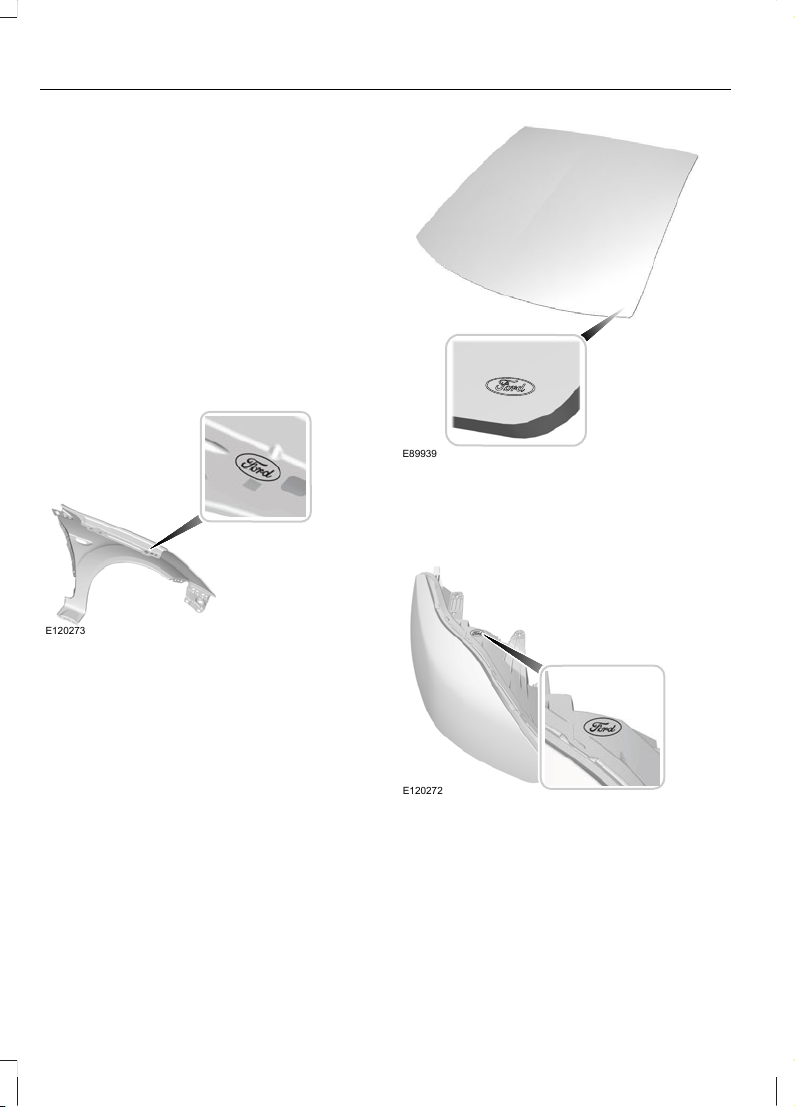
Now it is easier to tell if you have really
been given Ford Original Parts. The Ford
logo is clearly visible on the following parts
if they are Ford Original Parts. If your
vehicle has to be repaired, look for the
clearly visible Ford branding and make sure
that only Ford Original Parts have been
used.
Look for the Ford logo on the
following parts
Sheet metal
• Fenders
• Doors
E120273
Glass
• Rear window
• Side glass
• Windscreen
E89939
Lighting
• Headlamps
• Rear lamps
E120272
6
Introduction
Page 8
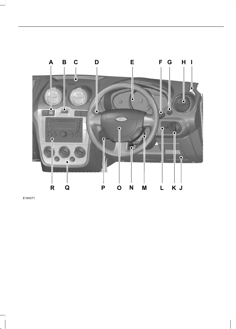
Instrument panel overview - RHD
EA
Q
J
CB H ID F G
KL
MP O
N
R
E154371
Heated rear window switch. See Heated Windows (page 50).A
Hazard warning flasher switch. See Hazard Warning Flashers (page 33).B
Storage tray.C
Direction indicators. See Direction Indicators (page 34). Main beam. See
Lighting Control (page 32).
D
Instrument cluster. See Gauges (page 42). See Warning Lamps and
Indicators (page 43).
E
Wiper lever. See Wipers and Washers (page 28).F
Luggage compartment release switch.G
Air vent. See Air Vents (page 47).H
Window demister.I
7
At a Glance
Page 9
Driver side storage compartment.J
Lighting control. See Lighting Control (page 32). Front fog lamps. See Front
Fog Lamps (page 33).
K
Headlamp levelling control. See Headlamp Levelling (page 32).L
Ignition switch. See Ignition Switch (page 57).M
Steering wheel adjustment. See Adjusting the Steering Wheel (page 26).N
Horn.O
Audio control. See Audio Control (page 26).P
Climate controls. See Climate Control (page 47).Q
Audio unit. See separate handbook.R
Engine idle speed after starting
The engine may idle at a higher speed than
normal immediately after starting from
cold. See Starting a Petrol Engine (page
57). See Starting a Diesel Engine (page
58).
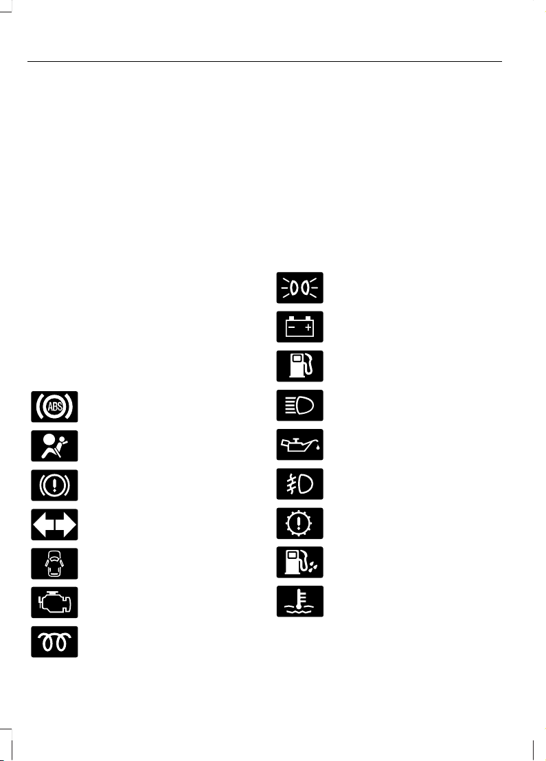
Warning lamps and indicators
ABS warning lamp
Airbag warning lamp
Brake system warning lamp
Direction indicator
Door open warning lamp
MIL (Malfunction indicator lamp)
Glow plug indicator
Illumination ON indicator
Ignition warning lamp
Low fuel level warning lamp
Main beam indicator
Oil pressure warning lamp
Front fog lamp indicator
Engine check warning lamp
Water in fuel warning lamp
Engine coolant temperature
warning lamp
8
At a Glance
Page 10
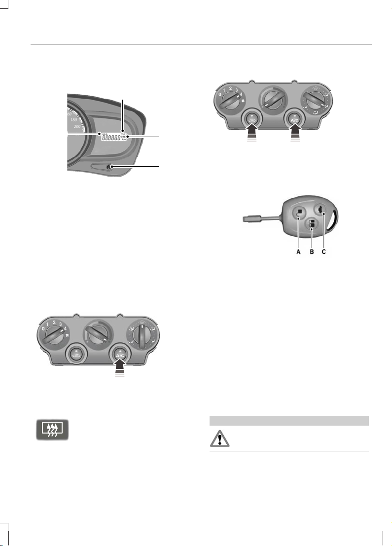
Information display
E120230
C
D
B
A
OdometerA
TripmeterB
Distance to emptyC
Reset buttonD
Press the Reset button to scroll through
the displays. See General Information
(page 46).
Defrosting and demisting the
windscreen
E123452
If necessary use the heated rear window
to defrost or demist the rear window. See
Heated Windows (page 50).
E72507
See Manual Climate Control (page 48).
Cooling the interior quickly
E90451
See Manual Climate Control (page 48).
Locking and unlocking the doors
with the remote control
E122028
UnlockA
LockB
Luggage compartment lid unlockC
Locking the doors
Press button B once.
Unlocking the luggage compartment
lid
Press button C twice within three seconds.
See Locking and Unlocking (page 22).
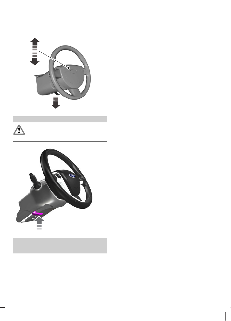
Adjusting the steering wheel
WARNING
Never adjust the steering wheel
when the vehicle is moving.
9
At a Glance
Page 11
1
2
E101516
WARNING
Make sure that you fully engage the
locking lever when returning it to its
original position.
3
E95179
See Adjusting the Steering Wheel
(page 26).
10
At a Glance
Page 12
BOOSTER SEATS
WARNINGS
Do not install a booster seat or a
booster cushion with only the lap
strap of the seat belt.
Do not install a booster seat or a
booster cushion with a seat belt that
is slack or twisted.
Do not put the seat belt under your
child’s arm or behind its back.
Do not use pillows, books or towels
to boost your child’s height.
Make sure that your children sit in an
upright position.
Secure children that weigh more
than 15 kilograms but are less than
150 centimetres tall in a booster seat
or a booster cushion.
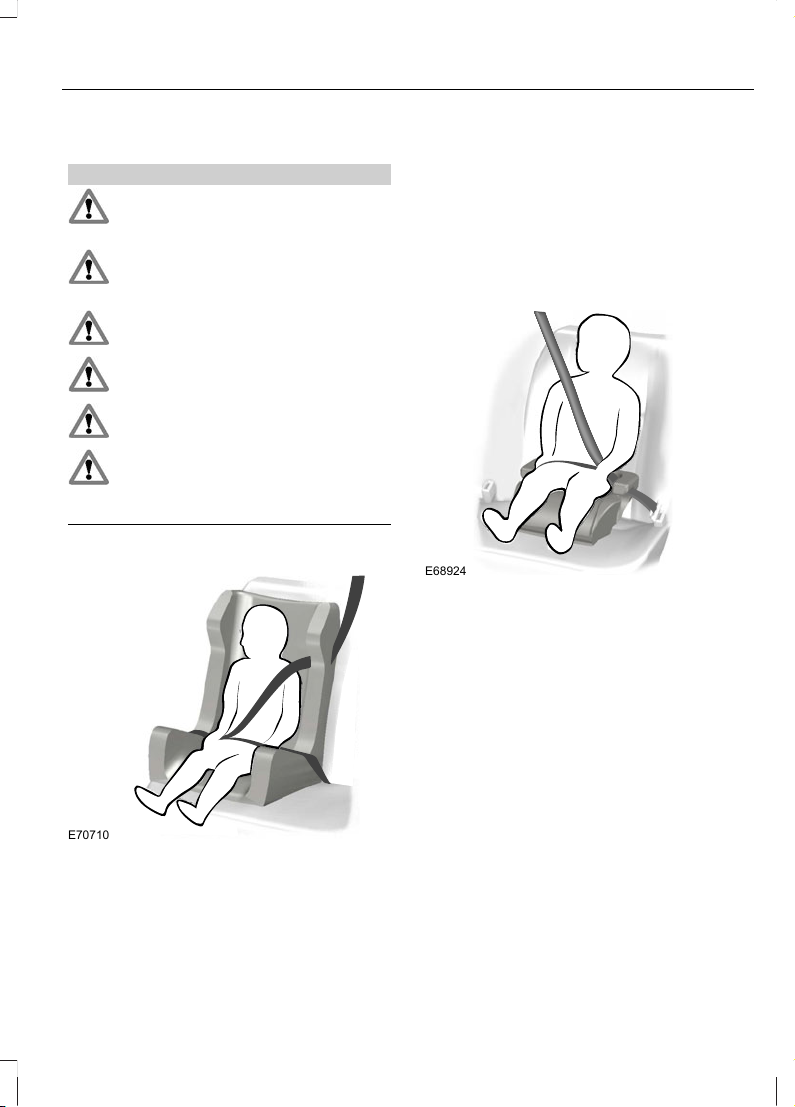
Booster seat (Group 2)
E70710
We recommend that you use a booster
seat that combines a cushion with a
backrest instead of a booster cushion only.
The raised seating position will allow you
to position the shoulder strap of the adult
seat belt over the centre of your child’s
shoulder and the lap strap tightly across
its hips.
Booster cushion (Group 3)
E68924
11
Child Safety
Page 13
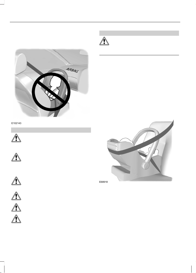
CHILD SEATS
E102143
WARNINGS
Secure children that are less than
150 centimetres tall or less than 12
years of age in a suitable, approved
child restraint, in the rear seat.
Original warning according to ECE
R94.01: Extreme Hazard! Do not use
a rearward facing child restraint on
a seat protected by an air bag in front of
it!
Read and follow the manufacturer’s
instructions when you are fitting a
child restraint.
Do not modify child restraints in any
way.
Do not hold a child on your lap when
the vehicle is moving.
Do not leave children unattended
inside your vehicle in a doors closed
condition.
WARNINGS
If your vehicle has been involved in
an accident, have the child restraints
checked by properly trained Ford
approved technicians.
Note: Mandatory use of child restraints
varies from country to country.
A choice of approved child restraints, which
have been specifically tested and
approved for your vehicle are available
from your Dealer.
Child restraints for different mass
groups
Use the correct child restraint as follows:
Baby safety seat
E68918
Secure children that weigh less than 13
kilograms in a rearward facing baby safety
seat (Group 0+) in the rear seat.
12
Child Safety
Page 14
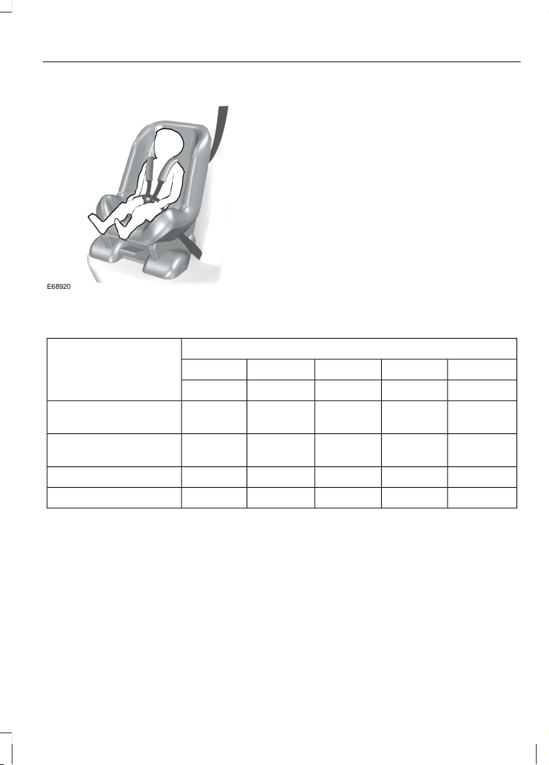
Child safety seat
E68920
Secure children that weigh between 13 and
18 kilograms in a child safety seat (Group
1) in the rear seat.
CHILD SEAT POSITIONING
Mass group categoriesSeating positions
IIIIII0+0
22 - 36 kg15 - 25 kg9 - 18 kgUp to 13 kgUp to 10 kg
UF
1
UF
1
UF
1
UF
1
UF
1
Front co-driver seat
(without PAB)
UF
1
UF
1
UF
1
XXFront co-driver seat
(with PAB)
UUUUURear seat (3 point belt)
XXXXXRear seat (lap belt only)
PAB - Passenger airbag.
X Not suitable for children in this mass group.
U Suitable for universal category child seats approved for use in this mass.
UF¹ Suitable for universal category forward facing child seats approved for use in this
mass group. However, we recommend that you secure children in a government approved
child restraint, in the rear seat.
13
Child Safety
Page 15
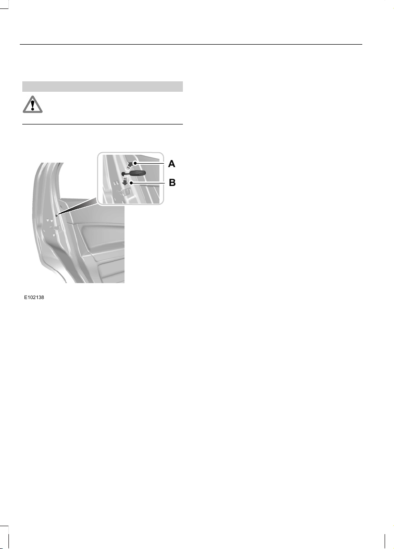
CHILD SAFETY LOCKS
WARNING
You cannot open the doors from
inside if you have put the child safety
locks on.
A
B
E102138
UnlockA
LockB
Turn the key in the rear door rearward to
activate the lock. To deactivate the lock,
turn the key forward.
14
Child Safety
Page 16
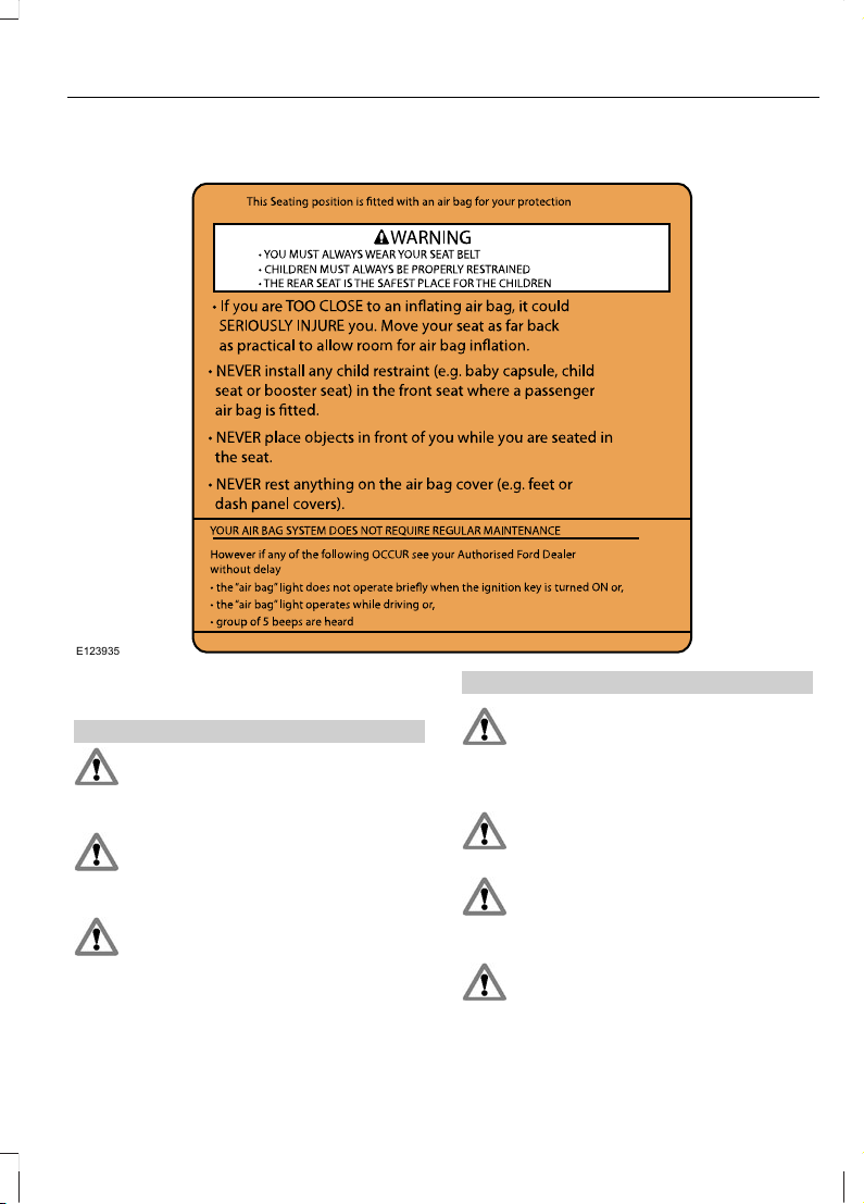
PRINCIPLE OF OPERATION
E123935
Airbags
WARNINGS
Do not modify the front of your
vehicle in any way. This could
adversely affect deployment of the
airbags.
Original warning according to ECE
R94.01: Extreme Hazard! Do not use
a rearward facing child restraint on
a seat protected by an airbag in front of it!
Wear a seat belt and keep sufficient
distance between yourself and the
steering wheel. Only when you use
the seat belt properly, can it hold you in a
position that allows the airbag to achieve
its optimum effect.
WARNINGS
Have repairs to the steering wheel,
steering column, seats, airbags and
seat belts carried out by properly
trained technicians from Ford authorised
dealerships.
Keep the areas in front of the airbags
free from obstruction. Do not affix
anything to or over the airbag covers.
Do not poke sharp objects into areas
where airbags are fitted. This could
damage and adversely affect
deployment of the airbags.
The airbag may only deploy with the
ignition switch in the on (II) position.
15
Occupant protection
Page 17
WARNINGS
Always keep the areas in front of the
airbags free. Never affix anything to
or over these areas.
If you are too close to an inflating
airbag, it could seriously injure you.
Move your seat as far back as
practical to allow room for airbag inflation.
Several airbag system components
get hot after inflation. Do not touch
after inflation.
Fitment of certain accessories e.g.
bull bars or nudge bars may cause
inadvertent or premature
deployment of air bags.
Note: You will hear a loud bang and see a
cloud of harmless powdery residue if an
airbag deploys. This is normal.
Note: Only wipe airbag covers with a damp
cloth.
Your vehicle is equipped with an event data
recorder which is capable of collecting and
storing data during a crash or near crash
event. The recorded information may assist
in the investigation of such an event. To
access this information special equipment
must be directly connected to the
recording modules. Ford does not access
event data recorder information without
obtaining consent unless pursuant to a
court order or where required by law
enforcement, other government authorities
or other third parties may seek access to
the information independent of Ford.
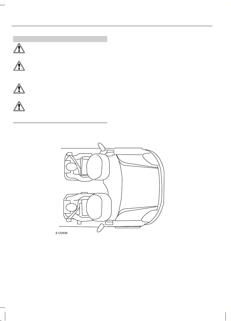
E123936
The airbag is a supplementary restraint
system. It is designed to be used in addition
to seat belts to help protect against head
and chest injuries in certain moderate to
severe frontal collisions.
The airbag system is not visible until it is
activated. The air bag system is designed
to deploy the driver and passenger front
air bags in certain frontal and front angled
collisions.
16
Occupant protection
Page 18
Because the system senses crash severity,
some frontal and side collisions will not
inflate the airbags. Front airbags are not
designed to inflate in rollover, rear and low
speed impacts.
The restraint system comprises:
• a driver airbag
• a front passenger airbag
• crash sensors
• an airbag warning lamp
• an electronic control and diagnostic
unit.
Driver and front passenger airbags
Your vehicle is equipped with an air bag for
the driver, located in the steering wheel
and a passenger air bag is located in the
instrument panel above the glove
compartment. The passenger air bag can
be identified by the ‘Airbag’ mark
embedded on the airbag cover.
The seat back must be set correctly for the
airbags to be optimally effective. See
Sitting in the Correct Position (page
51). This helps to reduce the risk of injury
from sitting too close to an inflating airbag.
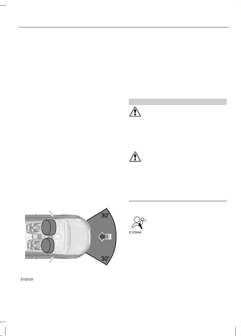
E102125
The driver and front passenger airbags will
deploy during significant frontal collisions
or collisions that are up to 30 degrees from
the left or the right. The airbags will inflate
within a few thousandths of a second and
deflate on contact with the occupants,
thus cushioning forward face/body
movement. During minor frontal collisions,
overturns, rear collisions and side
collisions, the driver and front passenger
airbags will not deploy.
WARNINGS
If the passenger airbag cover shows
signs of having been removed, the
car should be towed to the nearest
Authorised Ford Dealer for repair. Do not
attempt to reinstall the cover. If the vehicle
must be driven then on no account should
there be an occupant in the front
passenger seat.
The airbag(s) and energy
management retractors will activate
only once. Once activated, the
airbags and energy management retractors
will not function again and must be
replaced immediately. The crash sensor
must also be replaced. If the airbag(s) are
not replaced, the un-repaired area will
increase the risk of injury in a collision.
Airbag warning light
E123944
When the ignition switch is turned to
position II, the airbag warning light on the
instrument panel illuminates for
approximately 3 seconds to indicate that
the system is functional.
17
Occupant protection
Page 19
If the airbag warning light does not
illuminate, if it stays on or illuminates
intermittently or continuously while driving,
it means there is a malfunction. Have the
system checked by an Authorised Ford
Dealer.
Seat belts
WARNINGS
Wear a seat belt and keep sufficient
distance between yourself and the
steering wheel. Only when you use
the seat belt properly, it can hold you in a
position to achieve its optimum effect.
The wearing of seat belts is required
by law, even when airbags are fitted.
Never use a seat belt for more than
one person.
Use the correct buckle for each seat
belt.
Do not use a seat belt that is slack
or twisted.
Do not wear thick clothing. The seat
belt must fit tightly around your body
to achieve its optimum effect.
Position the shoulder strap of the
seat belt over the centre of your
shoulder and position the lap strap
tightly across your hips.
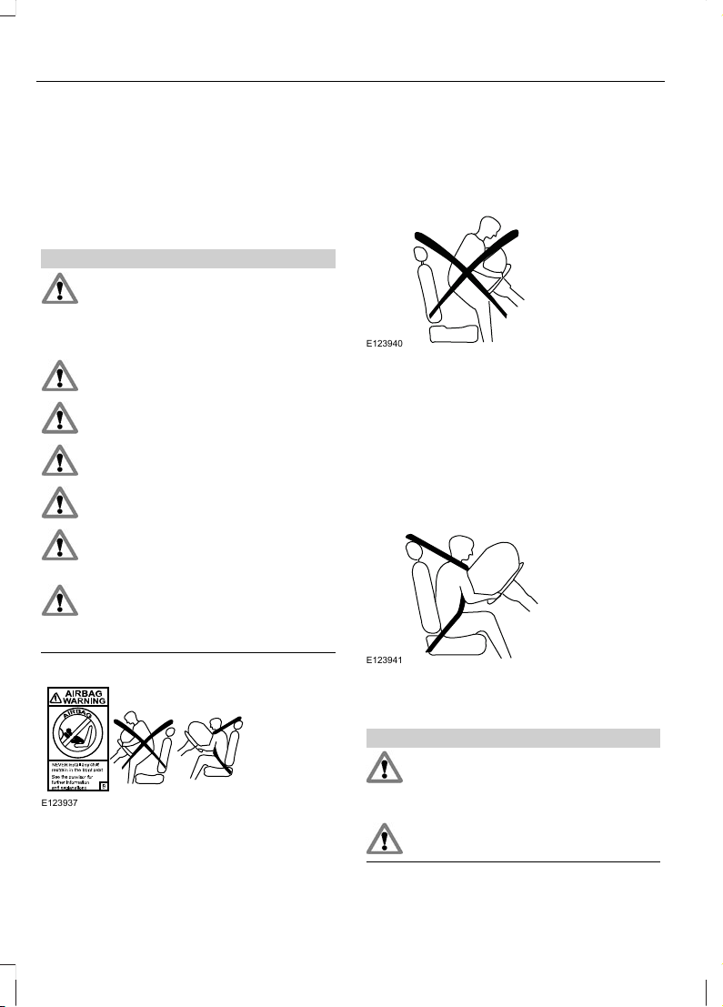
E123937
The importance of wearing seat belts
Seat belts must be worn by all vehicle
occupants to be properly restrained and
help reduce the risk of injury in a collision.
Wearing a seat belt will:
E123940
• help keep you in the proper position
when the airbags inflate,
• reduce the risk of harm in rollover, side
or rear impact collisions,
• reduce the risk of harm in frontal
collisions that are not severe enough
to activate the airbags,
• reduce the risk of being thrown from
your vehicle.
E123941
FASTENING THE SEAT BELTS
WARNINGS
Insert the tongue into the buckle until
you hear a distinct click. You have
not fastened the seat belt properly
if you do not hear a click.
Do not use a seat belt that is slack
or twisted.
18
Occupant protection
Page 20
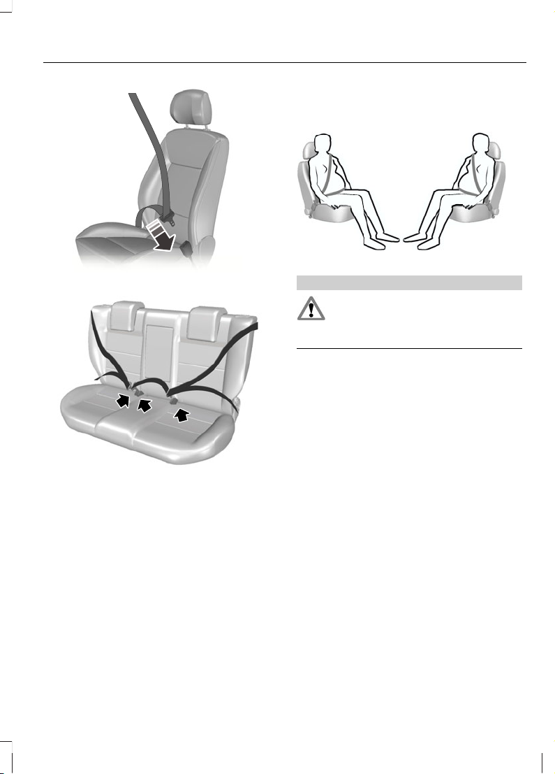
E74124
E102129
Pull the belt out steadily. It may lock if you
pull it sharply or if the vehicle is on a slope.
Press the red button on the buckle to
release the belt. Let it retract completely
and smoothly.
USING SEAT BELTS DURING
PREGNANCY
E68587
WARNING
Position the seat belt correctly for
your safety and that of your unborn
child. Do not use only the lap strap
or the shoulder strap.
Position the lap strap comfortably across
your hips and low beneath your pregnant
abdomen. Position the shoulder strap
between your breasts, above and to the
side of your pregnant abdomen.
19
Occupant protection
Page 21
GENERAL INFORMATION ON
RADIO FREQUENCIES
CAUTIONS
The radio frequency used by your
remote control can also be used by
other short distance radio
transmissions (e.g. amateur radios,
medical equipment, wireless headphones,
remote controls and alarm systems). If the
frequencies are jammed, you will not be
able to use your remote control. You can
lock and unlock the doors with the key.
Check your vehicle is locked before
leaving it unattended. This will
safeguard against any potential
malicious frequency blocking.
Note: You could unlock the doors if you
press the buttons on the remote control
unintentionally.
The operating range between your remote
control and your vehicle varies depending
on the environment.
PROGRAMMING THE REMOTE
CONTROL
A maximum of four remote controls
(Coded Keys) (including the ones supplied
with the vehicle) can be programmed.
E102144
To programme a new remote control:
• Turn the ignition key to position II four
times within six seconds.
• Switch off the ignition. Cluster indicator
flashes to indicate that it is now
possible to programme a new remote
control.
• Press any button on a new remote
control. Cluster indicator flashes as
confirmation. Repeat this last step for
all of your remote controls, including
the original.
• Switch the ignition back on or wait for
ten seconds without programming
another remote control to end remote
control programming. Only the remote
controls which you have just
programmed are now able to lock and
unlock your vehicle.
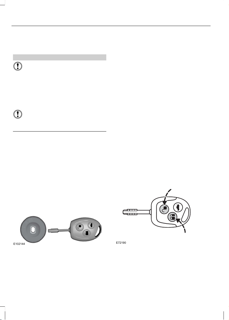
Re-programming the unlocking
function
You can change the unlocking function so
that pressing the unlock button once
deactivates the central locking and unlocks
the driver’s door. Pressing the unlock
button twice within three seconds also
unlocks the passengers’ doors.
E72190
20
Keys and Remote Controls
Page 22
In order to re-programme the function,
press and hold the unlock and lock buttons
simultaneously for at least four seconds
with the ignition switched off. The direction
indicators will flash twice to indicate that
the unlocking function has been
successfully re-programmed.
Pressing and holding both buttons
simultaneously for at least four seconds
again will change the function back.
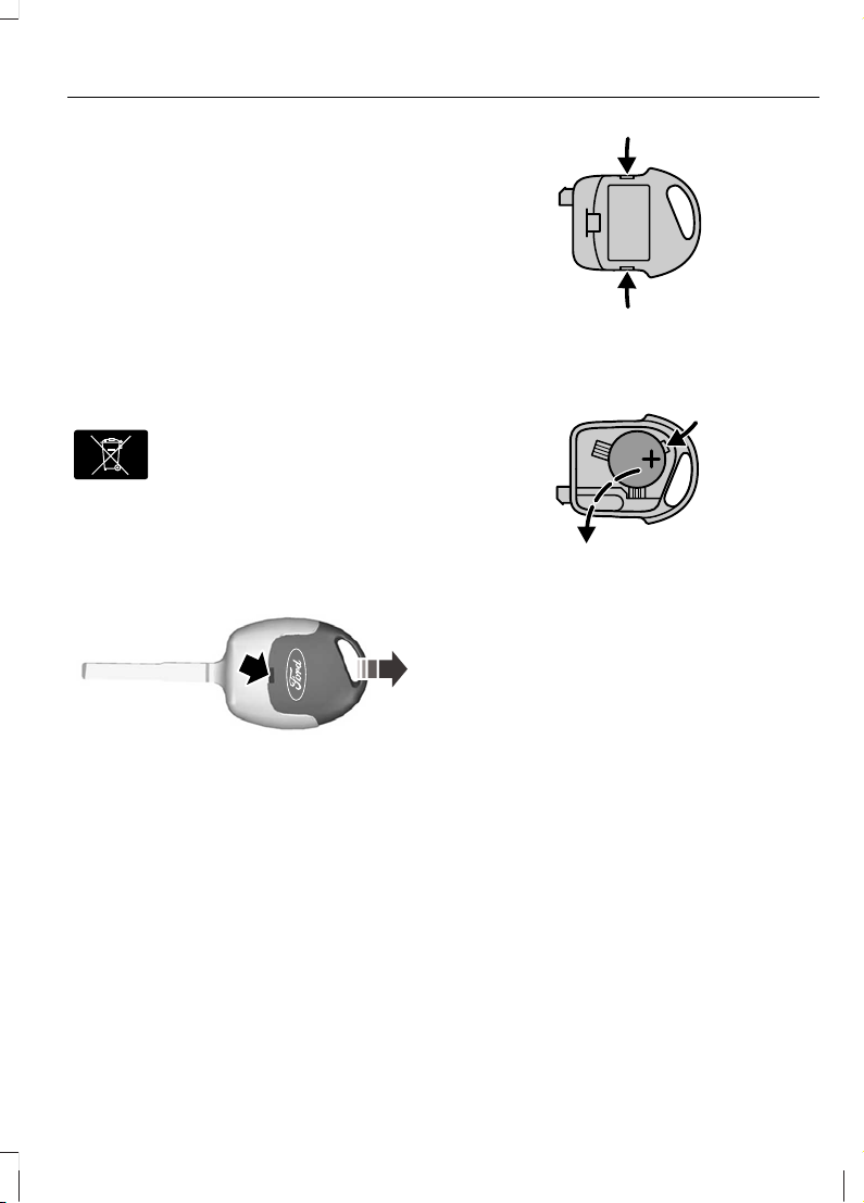
CHANGING THE REMOTE
CONTROL BATTERY
E107998
Make sure that you dispose of
old batteries in an
environmentally friendly way.
Seek advice from your local authority
regarding recycling.
If the range of the transmitter in the key
decreases gradually, the battery (type 3V
CR 2032) should be replaced.
E68726
• Carefully separate the transmitter unit
from the key using a flat object (e.g. a
screwdriver) at the recess on the back.
• Carefully prise out the battery with the
flat object. Fit the new battery between
the contacts with the + sign facing
downwards. Reassemble the
transmitter unit in reverse order.
E68727
• Open the transmitter unit by separating
the retaining clips on the sides with the
flat object.
E68729
• Carefully prise out the battery with the
flat object. Fit the new battery between
the contacts with the + sign facing
downwards. Reassemble the
transmitter unit in reverse order.
21
Keys and Remote Controls
Page 23
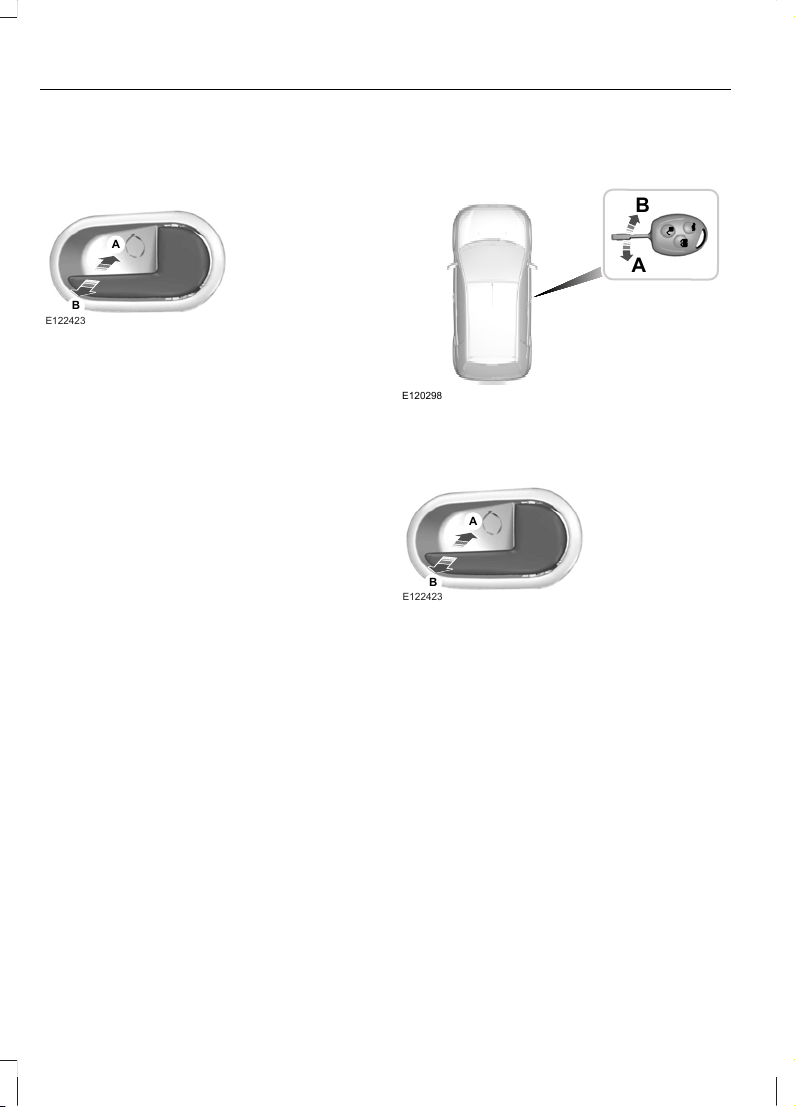
LOCKING AND UNLOCKING
Manual locking
A
B
E122423
Push to lockA
Pull to unlockB
You need to lock all the doors individually
and lock the driver side door with the key.
Central locking
You can only centrally lock the doors if they
are all closed. Central locking can only be
operated from driver door either by the
handle in the bezel or by the remote
control.
Locking and unlocking
confirmation
The direction indicators will flash once
while unlocking the doors using the remote
control.
The direction indicators will flash twice
while locking the doors using the remote
control.
Locking and unlocking the doors
with the key and inner handle
E120298
A
B
UnlockA
LockB
A
B
E122423
LockA
UnlockB
22
Locks
Page 24
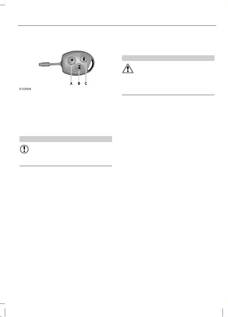
Locking and unlocking the doors
with the remote control
E122028
UnlockA
LockB
Luggage compartment lid unlockC
Locking the doors with the remote
control
CAUTION
Do not put metal accessories/other
immobilizer keys with the key bunch.
This may affect the engine
immobilizer function.
Note: Keep each key separate in order to
avoid a starting malfunction.
Remote will not operate at ignition on
position.
Press the appropriate button once.
Unlocking the luggage compartment
lid
Press button C twice within three seconds.
Automatic relocking
NOTE: To prevent the vehicle being left
unlocked inadvertently, central locking will
be reactivated automatically 45 seconds
after the unlock button is pressed, if the
following occurs during the period.
• No door is opened.
• The luggage compartment is not
opened.
• The ignition is not switched on.
WARNING
If a failure in the vehicle's electrical
system, the drivers door can be
unlocked with a key, the boot can be
still access through the folding rear seat
or boot lock (where respective feature
fitted).
Drive away locking
When the vehicle reaches a speed greater
than 7 Km/h, the central locking is
automatically applied.
Note: All the doors to be closed fully for
proper functioning of drive away locking.
Ignition off auto unlock
If the ignition is switched off the vehicle
will unlock automatically.
Vehicle Search
If the remote Lock button is pressed twice
within 0.5 seconds then the vehicle will
give few short flashes to easily identify your
vehicle amongst a group of vehicle.
Crash sensing door unlock
All doors will be automatically unlocked
when an impact causes the airbags to
deploy and following this the hazard
warning flashers will flash.
Luggage compartment
Opening the luggage compartment
The luggage compartment can be opened
either by remote or pressing the luggage
compartment release switch near the
instrument panel.
23
Locks
Page 25
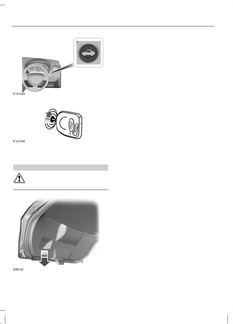
E121245
Using the key.
E121246
To unlock/open, turn the key clockwise.
Closing the luggage compartment
WARNING
Close the luggage compartment
properly to prevent it opening while
you are driving.
E89132
A recessed grip is incorporated inside the
luggage compartment lid to facilitate
closing.
24
Locks
Page 26

PRINCIPLE OF OPERATION
The engine immobiliser is a theft protection
system that prevents someone from
starting the engine with an incorrectly
coded key.
CODED KEYS
Note: Do not shield your keys with metal
objects. This may prevent the receiver from
recognising your key as a valid one.
Note: Have all of your remaining keys
erased and recoded if you lose a key. Ask
your dealer for further information. Have
replacement keys recoded together with
your existing keys.
If you lose a key, you can obtain a
replacement from your Ford Dealer. If
possible, provide them with the key
number from the tag provided with the
original keys. You can also obtain
additional keys from your Ford Dealer.
ARMING THE ENGINE
IMMOBILISER
The engine immobiliser is armed
automatically a short time after you have
switched the ignition off.
The indicator in the instrument cluster will
flash to confirm that the system is
operating.
DISARMING THE ENGINE
IMMOBILISER
Switching on the ignition disarms the
system if the correct code is recognised.
The indicator illuminates for
approximately three seconds and then
extinguishes.
If the indicator illuminates constantly for
one minute or flashes for approximately
one minute and then repeatedly at irregular
intervals, the system did not recognise the
key code or a system fault is present.
Remove the key and try again.
If the engine does not start, a system
malfunction has occurred. Have the system
checked by an expert immediately.
25
Engine immobiliser
Page 27
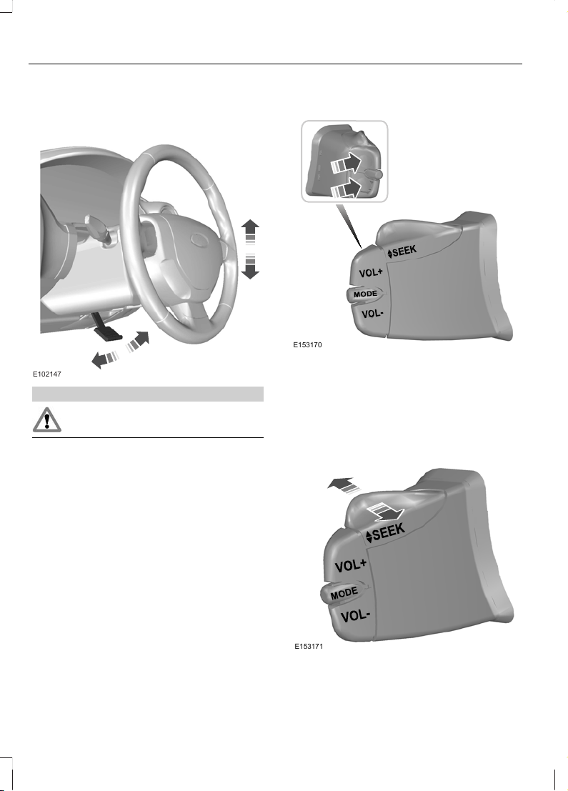
ADJUSTING THE STEERING
WHEEL
E102147
WARNING
Never adjust the steering wheel
when the vehicle is moving.
Release the locking lever to adjust the
height of the steering wheel.
Return the lever to its original position to
secure the wheel.
See Sitting in the Correct Position (page
51).
AUDIO CONTROL
Select radio, CD or cassette mode on the
audio unit.
The following functions can be operated
with the remote control:
Volume
E153170
Volume up: Press the VOL + button on the
back of the remote control.
Volume down: Press the VOL - button on
the back of the remote control.
Seek
E153171
Move the lever up or down:
26
Steering Wheel
Page 28
• In radio mode, this will locate the next
radio station up or down the frequency
band.
• In CD, MP3, USB and Bluetooth
audio mode, it will select the next or
previous track.
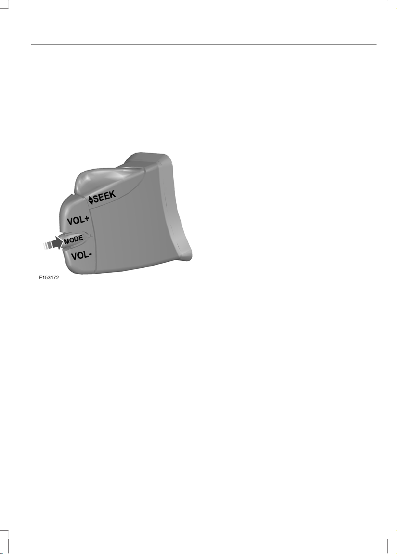
Mode
E153172
Briefly press the button on the side:
• In radio mode, this will locate the next
pre-set radio station.
• In MP3 and USB mode, this will play
first song of next folder.
Press and hold the button on the side:
• In all modes, this will change the mode
function to AM /FM/CD or
MP3/USB/Bluetooth audio/Aux.
27
Steering Wheel
Page 29

WINDSCREEN WIPERS
E124013
D
B
C
A
Single wipeA
Intermittent wipingB
Normal wipingC
High speed wipingD
Intermittent wiping
Fixed intermittent
E124015
B
Select the wiper switch to position B for
intermittent wiping.
However wiping delay can be programmed
as follows.
1. Switch on the ignition.
2. Set the wiper switch to intermittent
position.
3. Move the wiper switch to off position
when the wiper comes to park position.
Note: Wiping delay timing will start from
here to until the wiper switch is moved to
position B.
4. Move the wiper back to position B for
the required time delay.
Note: The user programmed timer resets,
when the wiper switch is moved to low/high
speed or when the ignition is switched off.
Variable intermittent
E124014
B
Select wipe interval with rotary switch: 1 =
Short time interval. 6 = Extended time
interval.
WINDSCREEN WASHERS
E72174
WARNING
Do not operate the windscreen
washer for more than 10 seconds or
when the reservoir is empty.
28
Wipers and Washers
Page 30
When the button at the end of the lever is
pressed the washer will work in
conjunction with the wiper operating four
times.
Once the wash/wipe cycle is completed,
the wipers will pause and then perform
one more wipe to clear the screen.
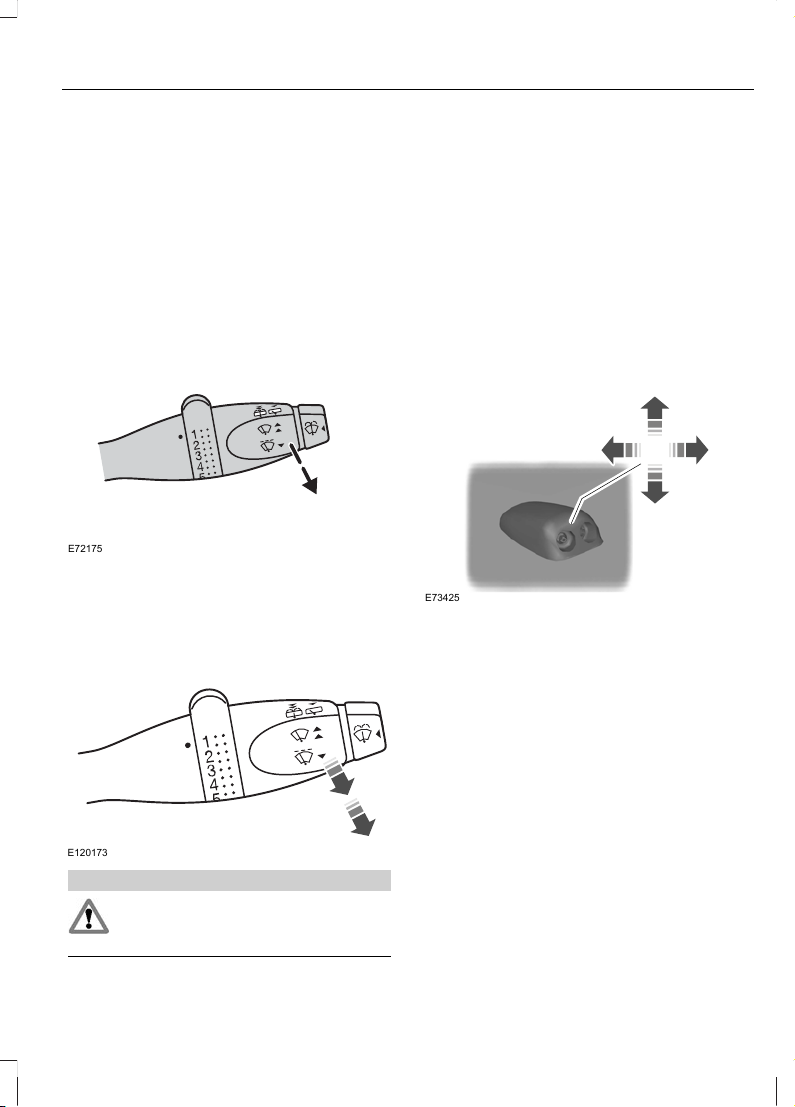
REAR WINDOW WIPER AND
WASHERS
E72175
Pull the lever towards the steering wheel.
Washer
E120173
WARNING
Do not operate the washer for more
than 10 seconds at a time, and never
when the reservoir is empty.
Pull the lever fully towards the steering
wheel and hold it to operate the washer.
The washer will operate in conjunction with
the wipers.
The washer jet for the rear window is
located on the central high mount stop
lamp above the rear window.
Note: Avoid dry wiping operation, this will
reduce the wiper rubber life.
ADJUSTING THE WINDSCREEN
WASHER JETS
E73425
The eye ball jets can be adjusted precisely
using a pin.
29
Wipers and Washers
Page 31

CHECKING THE WIPER
BLADES
E66644
Run the tip of your fingers over the edge of
the blade to check for roughness.
Clean the wiper blade lips with water
applied with a soft sponge.
CHANGING THE WIPER
BLADES
WARNING
Avoid the contact between wiper
arm and windscreen when the wiper
arm is placed over windscreen
without wiper blade.
Note: Ensure to keep a thick paper or foam
between the wiper arm and windscreen to
avoid scratches.
E102139
1
2
E93784
3
5
4
E93785
30
Wipers and Washers
Page 32

6
E93786
Install in the reverse order.
31
Wipers and Washers
Page 33

LIGHTING CONTROL
Lighting control positions
E126635
D
E
OffA
Side and tail lampsB
HeadlampsC
Front fog lampsD
Rear fog lampsE
Note: To remind you to switch off the
headlamps, a chime will come on when the
driver door is opened with headlamps on.
Welcome lighting
The side repeaters and tail lamps will flash
once when you unlock the doors with the
remote control. Courtesy lamp comes on
if the lamp control is in door mode.
Main/dipped beam
E102128
Pull the lever fully towards the steering
wheel to switch between main and dipped
beam.
Headlamp flasher
E102128
Pull the lever slightly towards the steering
wheel.
HEADLAMP LEVELLING
E102133
32
Lighting
Page 34

You can adjust the level of the headlamp
beams according to the vehicle load.
Recommended headlamp levelling switch positions
Control position
Load in luggage
compartment
Load
Rear seatsFront seats
0--1
0--1-2
1.0-31-2
1.5Max31-2
3.0Max-1
FRONT FOG LAMPS
E126656
Switch on the headlamps and pull out the
control switch one position.
The front fog lamps should be used only
when visibility is considerably restricted by
fog, snow or rain.
The indicator light in the instrument cluster
will illuminate, when the front fog lamps
are in use.
HAZARD WARNING FLASHERS
For item location: See At a Glance (page
7).
E124503
Use only in an emergency to warn other
traffic of vehicle breakdown or
approaching danger. Press the switch to
turn on or off.
You can also operate the hazard warning
flashers when the ignition is off.
Note: The hazard warning flashers flash
during emergency braking.
33
Lighting
Page 35

DIRECTION INDICATORS
E102191
Move the lever up/down to activate
right/left direction indicators respectively.
During lane changing flick the lever up or
down and the direction indicators will flash
three times.
Sudden increase in the rate of flashing
warns a failed indicator bulb.
INTERIOR LAMPS
Courtesy lamp
E120292
A
C
B
OffA
Door contactB
OnC
If you set the switch to position A, the
courtesy lamp will be off irrespective of
the doors being opened or closed.
If you set the switch to position B the
courtesy lamp turns on during the
following conditions.
High variantMid variantBase variant
Illuminates
1
Illuminates
1
Does not illuminate
Any of the 4 door
open
IlluminatesDoes not illuminate
Luggage compart-
ment open
1
- The illumination will have theatre dimming effect.
If you set the switch to position C, the
courtesy lamp will come on irrespective of
the door condition and ignition switch
position. It will go off automatically after
a short time to prevent the vehicle battery
from discharging. To switch it back on,
switch on the ignition for a short time.
34
Lighting
Page 36

Luggage compartment lamp
E120328
The luggage compartment lamp turns on
during the following conditions.
High variantMid variantBase variant
Illuminates
No Luggage
compartment lamp
fitted
No Luggage
compartment lamp
fitted
Any of the 4 door
open
Illuminates
Luggage compart-
ment open
CHANGING A BULB
WARNINGS
Switch the lights and the ignition off.
Let the bulb cool down before
removing it.
CAUTIONS
Do not touch the glass of the bulb.
Only fit bulbs of the correct
specification. See Bulb
Specification Chart (page 38).
Note: The following instructions describe
how to remove the bulbs. Fitting is the
reverse order unless otherwise stated.
Headlamp main and dipped beam
Note: To remove the right hand side
headlamp bulb, detach the coolant
reservoir.
Detach the coolant reservoir
E125296
2
1
1. Remove the bolt.
2. Pull the container from the bracket.
Headlamp bulb
35
Lighting
Page 37

1. Remove the headlamp cover.
1
2
4
3
E154463
2. Disconnect the electrical connector.
3. Release the clip.
4. Remove the bulb.
Side lamps
1. Remove the headlamp cover. See
headlamp bulb removal.
E154464
2. Carefully prise out the bulb holder.
3. Remove the bulb.
Front direction indicators
E154465
1. Turn the bulb holder anticlockwise and
remove it.
2. Gently press the bulb into the bulb
holder, turn it anticlockwise and
remove it.
Side repeaters
E120218
1
2
3
1. Carefully prise out the side repeater
assembly.
2. Turn the bulb holder anticlockwise and
pull it out.
3. Remove the bulb.
Rear lamps
1. Open the tailgate.
36
Lighting
Page 38

E154483
2. Unscrew the screws and remove the
rear lamp assembly.
3. Gently press the bulbs into the bulb
holder, turn them anticlockwise and
remove them.
A
B
C
E154484
Parking/Brake bulbA
Turn signal bulbB
Reverse lamp bulbC
Central high mounted stop lamp
2 3
E154784
4
1. Open the tailgate.
2. Remove the rubber grommet.
3. Release the clips using a flat-bladed
screwdriver, remove the lamp and
disconnect the connector.
4. Unclip the bulb holder and remove the
bulb.
37
Lighting
Page 39

Number plate lamp
E90601
1. Loosen the screws and remove the
lamp.
2. Remove the bulb.
Courtesy lamp
E120231
1
2
3
1. Carefully prise out the lamp.
2. Turn the bulb holder anticlockwise and
remove it.
3. Remove the bulb.
Luggage compartment lamp
E72784
1. Carefully prise out the lamp.
2. Remove the bulb.
BULB SPECIFICATION CHART
Rating (watt)SpecificationBulb
21PY21WFront direction indicator
5P21/5WSide lamp
55/60H4Headlamp
38
Lighting
Page 40

Rating (watt)SpecificationBulb
5WYW5Side repeater
55H11Front fog lamp
5P21/5WBrake and parking lamp (rear)
21P21WRear direction indicator
21P21WReversing lamp and rear fog lamp
16W16WCentral high mounted stop lamp
5CW5Number plate lamp
6W6WCourtesy lamp
5W6WLuggage compartment lamp
39
Lighting
Page 41

POWER WINDOWS
WARNING
Do not operate the electric windows
unless they are free from obstruction.
Note: If you operate the switches often
during a short period of time, the system
might become inoperable for a certain time
to prevent damage due to overheating.
The power windows can be operated only
when the ignition is switched on.
The front power window can be operated
by the switches located on either of the
door trims (driver door and front passenger
door). To lower or raise the window, press
or pull the power window switch
respectively.
E120219
Manual windows
E120310
To raise/lower the window rotate the
handle.
Note: The rear window cannot be fully
lowered.
EXTERIOR MIRRORS
Folding mirrors
E102162
You can fold back your exterior mirror in
narrow spaces or when the vehicle is
parked to avoid accidental damage to the
mirrors.
Make sure that you fully engage the mirror
in its support when returning it to its
original position.
40
Windows and Mirrors
Page 42

WARNING
Do not overestimate the distance of
the objects that you see in the
exterior mirror. Objects seen in the
mirror will appear smaller and further away
than they actually are.
Manual Exterior Mirrors
E123951
Both door mirrors are adjustable from
inside the vehicle.
ELECTRIC EXTERIOR
MIRRORS
E71280
B
C
A
Left-hand mirrorA
OffB
Right-hand mirrorC
E71281
INTERIOR MIRROR
E71272
Dip the mirror to reduce glare when driving
at night.
41
Windows and Mirrors
Page 43

GAUGES
Type A
C
B
D
A
E
E120228
Type B
E120229
C
B
D
E
TachometerA
Fuel gaugeB
SpeedometerC
Reset buttonD
Information displayE
42
Instrument Cluster
Page 44

Theater dimming
The instrument cluster illuminates
gradually with a theater dimming effect
when the side lamps are switched on.
Fuel gauge
E121144
CAUTION
Check the fuel level prior starting the
journey.
The arrow adjacent to the fuel pump
symbol tells you on which side of your
vehicle the fuel filler cap is located.
The low fuel level warning light illuminates
at approximately 80 kms before the tank
is empty and audible chimes will be heard
to alert you at 80 kms, 40 kms, 20 kms and
at empty respectively. Refuel as soon as
possible.
Tachometer
Indicates the current engine speed.
Speedometer
Indicates the current vehicle speed.
WARNING LAMPS AND
INDICATORS
The following warning lamps and
indicators will come on briefly when you
switch the ignition on to confirm that the
system is operational:
• Brake warning lamp
• Door open warning lamp
• Engine coolant temperature warning
lamp
• ABS warning lamp
• Low fuel warning lamp
• Airbag warning lamp
• PATS
• Engine check warning lamp
• Water in fuel warning lamp
• MIL (malfunction indicator warning
lamp)
If a warning or indicator lamp does not
illuminate when the ignition is switched
on, it indicates a malfunction. Have the
system checked as soon as possible.
ABS warning lamp
If ABS warning lamp illuminates
(with audible chimes) when you
are driving, this indicates a
malfunction. You will continue to have
normal braking (without ABS) but have
this checked as soon as possible.
Airbag warning lamp
If the airbag warning lamp
illuminates when you are driving,
this indicates a malfunction.
Have this checked as soon as possible.
43
Instrument Cluster
Page 45

Brake system warning lamp
WARNING
Reduce your speed gradually. Use
your brakes with great care. Do not
step on the brake pedal abruptly.
The brake system warning lamp
illuminates (with audible
chimes) when:
• the parking brake is engaged.
• low brake fluid.
• EBD (Electronic brake force
distribution) failure in ABS equipped
vehicles.
The brake system warning lamp will stay
on until you release the parking brake. If it
illuminates when you are driving, this
indicates a malfunction in one of the brake
circuits. Check the brake fluid level. See
Brake and Clutch Fluid Check (page 83).
WARNING
If the brake system warning lamp
comes on with the ABS warning
lamp, this indicates a malfunction.
Stop your vehicle as soon as it is safe to
do so and have this checked before
continuing you journey.
Door open warning lamp
The door open warning lamp
illuminates (with audible
chimes) if a door or the tailgate
is open, only when engine is running.
MIL
If the malfunction indicator
warning lamp illuminates when
the engine is running, this
indicates a malfunction. If it flashes when
you are driving, reduce the speed of your
vehicle immediately. If it continues to flash,
avoid heavy acceleration or deceleration.
The engine will continue to run but it will
have limited power. Have this checked
immediately.
Ignition warning lamp
If the ignition warning lamp
illuminates (with audible
chimes) when you are driving,
this indicates a malfunction. Switch off all
unnecessary electrical equipment and
have this checked immediately.
Low fuel level warning lamp
If the low fuel level warning lamp
illuminates (with audible
chimes), refuel as soon as
possible. See Gauges (page 42).
Oil pressure warning lamp
CAUTION
Do not resume your journey if the oil
pressure warning lamp comes on
despite the oil level being correct.
Have this checked immediately.
If the oil pressure warning lamp
illuminates (with audible
chimes) when you are driving,
this indicates a malfunction. Stop your
vehicle as soon as it is safe to do so and
switch the engine off. Check the engine oil
level. See Engine Oil Check (page 81).
44
Instrument Cluster
Page 46

Engine check warning lamp
If the engine check warning lamp
illuminates when the engine is
running, this indicates a
malfunction. The engine will continue to
run but it will have limited power. Have this
checked as soon as possible.
Front fog lamp indicator
It will illuminate when you switch
the front fog lamps on.
Water in fuel warning lamp
(vehicles with diesel engine)
If the water in fuel warning lamp
illuminates whilst driving
immediately see an Authorised
Ford Dealer to have the water drained from
the fuel filter.
CAUTION
Failure to do so could damage the
vehicle's fuel injection system causing
engine failure.
Note: Such failures are not covered under
warranty repair.
Engine coolant temperature
warning lamp
If it stays on after starting or
illuminates (with audible
chimes) when driving, this
indicates a malfunction. Stop your vehicle
as soon as it is safe to do so and switch the
engine off. Check the coolant level. See
Engine Coolant Check (page 83).
CAUTIONS
Do not resume your journey if it
illuminates despite the level being
correct. Have the system checked by
a properly trained technician immediately.
CAUTIONS
Do not restart the engine until the
cause of overheating has been
resolved.
Glow plug indicator
See Starting a Diesel Engine
(page 58).
Main beam indicator
The main beam indicator
illuminates when you switch the
headlamp main beam on. It will
flash when you use the headlamp flasher.
Illumination ON indicator
The illumination on indicator
illuminates when the side lamps
are switched on.
Direction indicator
The direction indicator will flash
when you use the direction
indicators. A sudden increase in
the rate of flashing warns of a failed bulb.
45
Instrument Cluster
Page 47

GENERAL INFORMATION
WARNING
Do not operate the information
display controls when the vehicle is
moving. The driver should at all times
be alert and focus his attention on the road
ahead only.
Note: The information display will remain
on for several minutes after you switch off
the ignition.
Information display
E120230
C
D
B
A
OdometerA
TripmeterB
Distance to emptyC
Reset buttonD
Press the reset button to scroll through the
displays.
Note: The information display illuminates
when the driver door is opened.
Display definitions
Tripmeter
Note: The maximum value for tripmeter is
9999.9kms and after that it automatically
resets and starts from zero.
The tripmeter can register the mileage of
individual journeys.
Distance to empty
Indicates the approximate distance that
your vehicle will travel on the fuel in the
fuel tank.
Distance to empty display will stay on for
approximately 5 seconds when the igntion
is switched on and then cluster will go back
to the pre-set mode.
Odometer
Note: The maximum value for odometer
measurement is 999,999 kms after that it
automatically resets and starts from zero.
Registers the total mileage of the vehicle.
Reset button
A short press toggles the display between
odometer/trip/distance to empty.
A long press of more than two seconds
resets the trip to zero.
46
Information Displays
Page 48

PRINCIPLE OF OPERATION
Outside air
In this mode the climate control system
utilizes outside air.
Cowl filter and wire mesh filter
These filters remove the dust that is
brought in from the outside air through the
cooling and heating system, when the
blower is operated.
Have your dealer replace/clean the filters
as mentioned in the Periodical
maintenance schedule.
Recirculated air
CAUTION
Prolonged use of recirculated air may
cause the windows to mist up. If the
windows mist up, follow the settings
for defrosting and demisting the
windscreen.
The air currently in the passenger
compartment will be recirculated. Outside
air will not enter the vehicle.
Ensure maximum utilization of the
recirculation mode to avoid dust entering
into the passenger compartment and bad
smell entering from outside.
Heating
The purpose of heating is to heat the
interior compartment in cold weather
conditions.
Heating performance depends on the
temperature of the engine coolant.
Air conditioning
The purpose of air conditioning is to cool
the interior compartment.
Air is directed through the evaporator
where it is cooled. Humidity is extracted
from the air to help keep the windows free
of mist. The resulting condensation is
directed to the outside of the vehicle and
it is therefore normal if you see a small
pool of water under your vehicle.
If you use the air conditioning, the fuel
consumption of your vehicle will be higher.
Note: The air conditioning operates only
when the temperature is above 4ºC (39ºF).
General information on controlling
the interior climate
Warming the interior
Direct the air towards your feet. In cold or
humid weather conditions, direct some of
the air towards the windscreen and the
door windows.
Cooling the interior
Direct the air towards your face.
AIR VENTS
E71942
47
Climate Control
Page 49

MANUAL CLIMATE CONTROL
Blower
E124410
A
Off positionA
Temperature control
E124411
A
B
Cold side - Blue in colourA
Warm side - Red in colourB
Air distribution control
E124416
A
B
C
D
F
E
WindscreenA
Footwell and windscreenB
Face levelC
Face level and footwellD
FootwellE
Face level, windscreen and
footwell
F
You can set the air distribution control to
any position between the symbols.
A small amount of air is always directed
towards the windscreen.
Defrosting and demisting the
windscreen
E123452
Steps to be followed:
1. Set air distribution control to
windscreen.
2. Switch off the recirculation mode.
3. Set the temperature control knob to
maximum hot position.
48
Climate Control
Page 50

4. Set the blower to maximum speed.
5. Switch on the A/C.
If necessary, switch the heated windows
on in the instrument panel. See Heated
Windows (page 50).
E72507
Ventilation
There are two types of ventilation.
Normal ventilation
Use outside/fresh air mode. Air will flow
from outside through the air vents during
driving with the blower in off position. The
air distribution control mode can be at any
desired position.
Forced ventilation
In this type of ventilation the blower can
be positioned at any speed and the rest
are same as normal ventilation.
Switching the air conditioning on
and off
E124402
Press the button, to switch on/off the A/C.
If you turn the blower off, the air
conditioning will turn off. When you turn
the blower on again, the air conditioning
will come on automatically (if the A/C
switch is in on position).
Switching the recirculated air on
and off
E124407
Press the recirculated air button to switch
on/off.
To use the outside/fresh air switch off the
recirculation mode.
The last setting will be kept in memory,
press the recirculated air button to change
over to the other mode.
Cooling with outside air
E90450
Cooling the interior quickly
E90451
Steps to be followed:
1. Switch on the blower to maximum
speed.
2. Open the windows for 2-3 minutes to
allow the inside hot air to go out.
3. Switch on the A/C and recirculation
mode.
49
Climate Control
Page 51

4. Set the temperature control knob to
maximum cold position.
5. Close the windows and set the blower
to 2nd speed or to your convenience.
Heating the interior quickly
E90449
Reducing interior air humidity
E90452
HEATED WINDOWS
Use the heated rear window to defrost or
demist the rear window.
E124041
The heating of rear window will function
only when the ignition Key is in run position
or ON position. Also this has a timer to auto
cut-off the heating of rear window
operation.
The heated rear window switch is located
in the instrument panel.
E124040
50
Climate Control
Page 52

SITTING IN THE CORRECT
POSITION
E68595
WARNINGS
Do not adjust the seats when the
vehicle is moving.
Only when you use the seat belt
properly, can it hold you in a position
that allows the airbag to achieve its
optimum effect.
When you use them properly, the seat,
head restraint, seat belt and airbags will
provide optimum protection in the event
of a collision. We recommend that you:
• sit in an upright position with the base
of your spine as far back as possible.
• do not recline the seatback more than
30 degrees.
• adjust the head restraint so that the
top of it is level with the top of your
head and as far forwards as possible,
remaining comfortable.
• keep sufficient distance between
yourself and the steering wheel. We
recommend a minimum of 250
millimetres (10 inches) between your
breastbone and the airbag cover.
• hold the steering wheel with your arms
slightly bent.
• bend your legs slightly so that you can
press the pedals fully.
• position the shoulder strap of the seat
belt over the centre of your shoulder
and position the lap strap tightly across
your hips.
Make sure that your driving position is
comfortable and that you can maintain full
control of your vehicle.
MANUAL SEATS
Moving the seats backwards and
forwards
2
2
1
E102370
Raise the lever to unlock the seat
from track
1
Seat forward and rearward
movement
2
51
Seats
Page 53

WARNING
Rock the seat backwards and
forwards after releasing the lever to
make sure that it is fully engaged in
its catch.
Adjusting the height of the driver’s
seat
CAUTION
Do not perform seat cushion height
adjustment while driving.
E102371
Pull the lever upward to raise the driver
seat cushion.
Push the lever downward to lower the
driver seat cushion
Adjusting the angle of the
seatback
E102372
To adjust the front seatback, lift the handle
and hold in the fully up position.
Adjust the seatback to the required back
angle then release the adjustment handle.
Slight rocking of the seatback may be
required to ensure engagement.
The handle will return to the downward
position when locked.
52
Seats
Page 54

HEAD RESTRAINTS
E75767
Adjusting the head restraint
Adjust the head restraint so that the top
of it is level with the top of your head.
Removing the head restraint
Press the locking buttons and remove the
head restraint.
REAR SEATS
WARNING
Make sure that the seats and the
seatbacks are secured and fully
engaged in their catches.
Folding the seatbacks down
WARNING
When folding the seatbacks down,
take care not to get your fingers
caught between the seatback and
seat frame.
E123947
1
1
2
1. Push the unlock levers.
2. Push the seatback forwards.
Creating a level load floor
WARNING
Make sure the red indicator is not
showing when you engage the seat
in the catches.
53
Seats
Page 55

E123948
2
1
2
3
1. Insert your fingers between the seat
cushion and seatback and fold the seat
cushion forwards.
2. Push the unlock levers.
3. Push the seatback forwards.
WARNING
When folding the seatbacks up,
make sure that the belts are visible
to an occupant and not caught
behind the seat.
E123949
54
Seats
Page 56

SUN VISORS
E66493
The sun visors can be released from the
retention clips and swivelled towards the
side window. The sun visor on the front
passenger side also has a mirror in it.
AUXILIARY POWER POINTS
CAUTION
If you use the socket when the engine
is not running, the battery may
discharge.
The power socket can be used to power 12
volt electrical appliances having a
maximum current rating of 10 amperes.
E120275
When connecting to appliances, use only
specified connectors from the Ford
Accessory range or connectors suitable for
use with SAE standard sockets.
Audio jack
Audio jack is provided in the audio panel.
It is used for connecting MP3 players,
iPod's, etc, to the audio system.
E122031
GLOVE BOX
A
B
E102199
B
Card holderA
Coin holdersB
55
Convenience features
Page 57

Note: Do not store heavy and bulky items
in the glove box as it may lead to failure of
the glove box securing lock.
USB PORT
The USB port is located inside the glove
box.
56
Convenience features
Page 58

GENERAL INFORMATION
General points on starting
If the battery has been disconnected the
vehicle may exhibit some unusual driving
characteristics for approx. 8 kilometres (5
miles) after reconnecting the battery.
This is because the engine management
system must realign itself with the engine.
Any unusual driving characteristics during
this period may be disregarded.
The starter should not be operated for
longer than 10 seconds during each start
cycle. Release the ignition key as soon as
the engine has started. If the engine has
not started, return the ignition key to
position O and repeat the starting
procedure.
If the engine does not start, See Fuel
Cut-Off Switch (page 68).
Starting the engine by towing or
pushing
WARNING
To prevent damage you must not
push or tow start your vehicle. Use
booster cables and a booster battery.
See Jump-Starting the Vehicle (page
90).
IGNITION SWITCH
Ignition switch positions
Position 0
WARNING
Never return the key to the 0 position
when the vehicle is in motion.
Ignition off. When the key is removed from
the ignition switch, the steering column
lock will be activated as soon as the
steering wheel is turned.
Position I
Steering unlocked. Ignition and all main
electrical circuits are disabled. The ignition
key should not be left in this position for
too long to avoid discharging the battery.
Positon II
Ignition switched on, all electrical circuits
operational. Warning and indicator lamps
illuminate. This is the key position when
driving, and must also be selected when
being towed.
Postion III
Starter motor activated. Release the key
as soon as the engine starts.
STARTING A PETROL ENGINE
Note: You can only operate the starter for
a maximum of 10 seconds at a time.
Cold or hot engine
All vehicles
CAUTION
When the temperature is below -10ºC,
switch the ignition on for at least one
second before starting the engine.
This will make sure that the maximum fuel
pressure is established for starting the
engine.
Note: Do not touch the accelerator pedal.
1. Fully depress the clutch pedal.
2. Start the engine.
57
Starting and Stopping the Engine
Page 59

If the engine does not start within 10
seconds, wait for a short period and try
again.
If the engine does not start after three
attempts, wait 10 seconds and follow the
Flooded engine procedure.
If you have difficulty starting the engine
when the temperature is below -10ºC,
press the accelerator pedal between ¼ to
½ of its travel and try again.
Flooded engine
1. Fully depress the clutch pedal.
2. Fully depress the accelerator pedal and
hold it there.
3. Start the engine.
If the engine does not start, repeat the
Cold or hot engine procedure.
Engine idle speed after starting
The speed at which the engine idles
immediately after starting will vary
depending on the engine temperature.
If the engine is cold then the idle speed will
automatically be increased.
The idle speed will slowly decrease to the
normal level as the engine warms up.
STARTING A DIESEL ENGINE
Cold or hot engine
Note: When the temperature is below
-10ºC, you may need to crank the engine for
up to 10 seconds. To aid ease of cranking,
turn the ignition key to position II for at least
couple of seconds before starting the
engine. This ensures that maximum fuel
pressure is established.
Note: Continue cranking the engine until it
starts.
Note: You can only operate the starter for
a maximum of 10 seconds at a time.
Switch the ignition on and wait
until the glow plug indicator goes
off.
Note: Do not touch the accelerator pedal.
1. Fully depress the clutch pedal.
2. Start the engine.
3. Repeat this exercise for 3 to 4 times
until the engine cranks properly.
Note: If starting difficulty is experienced at
temperatures below -10ºC, depress the
accelerator pedal 1/4 to ½ of its travel to
assist starting. This should be done only, if
the engine fails to start after several
attempts of cranking as given in the above
steps.
Flooded Engine
Note: Do not depress the accelerator pedal
fully.
1. Depress the clutch pedal fully.
2. Slowly, depress the accelerator fully,
hold it in this position and start the
engine.
3. If the engine does not start repeat this
exercise for 3 to 4 times.
SWITCHING OFF THE ENGINE
Vehicles with a turbocharger
CAUTION
Do not switch the engine off when it
is running at high speed. If you do, the
turbocharger will continue running
after the engine oil pressure has dropped
to zero. This will lead to premature
turbocharger bearing wear.
Release the accelerator pedal. Wait until
the engine has reached idle speed and then
switch it off.
58
Starting and Stopping the Engine
Page 60

SAFETY PRECAUTIONS
WARNINGS
Stop refuelling after the fuel nozzle
stops the second time. Additional
fuel will fill the expansion space in
the fuel tank which could lead to fuel
overflowing. Fuel spillage could be
hazardous to other road users.
Do not use any kind of flames or heat
near the fuel system. The fuel system
is under pressure. There is a risk of
injury if the fuel system is leaking.
CATALYTIC CONVERTER
WARNING
Do not park or idle your vehicle over
dry leaves, dry grass or other
combustible materials. The exhaust
will radiate a considerable amount of heat
during use, and after you have switched
the engine off. This is a potential fire
hazard.
Driving with a catalytic converter
CAUTIONS
Avoid running out of fuel.
Do not crank the engine for long
periods.
Do not run the engine when a spark
plug lead is disconnected.
Do not push-start or tow-start your
vehicle. Use booster cables. See
Jump-Starting the Vehicle (page
90).
Do not switch the ignition off when
driving.
FUEL FILLER FLAP
Pull the release lever located in the floor
to the side of front driver seat for opening
the fuel filler flap.
E120174
Turn the cap anti-clockwise to remove.
When the filler cap is removed, a hissing
noise may be heard. This is normal and
should be disregarded.
To close, turn the cap clockwise until it
engages fully.
E120197
59
Fuel and Refuelling
Page 61

REFUELLING
CAUTION
Do not attempt to start the engine if
you have filled the fuel tank with the
incorrect fuel. This could damage the
engine. Have the system checked by a
properly trained technician immediately.
FUEL QUALITY - PETROL
Note: Add 1 ml of IFTEX System G with
every litre of Gasoline (Petrol). It is available
at all Ford authorised dealerships.
CAUTION
Do not use leaded petrol or petrol with
additives containing other metallic
compounds (e.g. manganese-based).
They could damage the emission system.
Use minimum 91 octane unleaded petrol
that meets the specification defined by EN
228, or equivalent.
FUEL QUALITY - DIESEL
Note: We recommend that you use only
high quality fuel without additives or other
engine treatments.
WARNING
Do not mix diesel with oil, petrol or
other liquids. This could cause a
chemical reaction.
CAUTION
Do not add kerosene, paraffin or
petrol to diesel. This could cause
damage to the fuel system.
Use diesel that meets the specification
defined by EN 590, or equivalent.
You can use diesel that contains up to 5%
RME (bio diesel).
Prolonged use of supplemental additives
to prevent fuel waxing is not
recommended.
FUEL CONSUMPTION
Length of journey/engine
temperature
Frequent cold starts and short distance
driving leads to considerably increased fuel
usage.
Traffic and road conditions
Slow moving traffic, uphill driving, frequent
sharp bends and rough roads all have an
adverse effect on fuel consumption.
Erratic driving habits
Anticipate hazards ahead and keep a safe
distance from the vehicle in front.
This not only reduces fuel consumption
but also the noise level.
If you have a prolonged wait at a railway
crossing or at traffic lights in built-up areas,
it is advisable to switch off the engine
during this period.
Vehicle load conditions
Driving in a fully laden condition will result
in high fuel consumption.
Vehicle condition
Low tyre pressure or inadequate engine or
vehicle maintenance will also result in
higher fuel consumption.
60
Fuel and Refuelling
Page 62

Transmission
MANUAL TRANSMISSION
WARNINGS
Engage reverse gear only when the
vehicle is stationary.
Do not apply any undue lateral force
to the gear lever when changing from
5th to 4th gear as this could lead to
the inadvertent selection of 2nd gear.
Reverse gear
To select the reverse gear, shi the lever
into the neutral position and then press the
lever fully to the right against a spring
pressure, before pulling rearwards.
Driving speed and gear selection
1.2L Petrol
Speed rangeGear
1.4L Diesel
Speed rangeGear
Engine RPM
range
800-20000-151
1100-225015-302
1500-225030-453
1700-225045-604
>1750>605
Engine RPM
range
750-17500-151
1000-200015-302
1400-200030-453
1500-200045-604
>1750>605
E99077
Note: The reverse gear should be engaged
only when the vehicle is stationary.
To avoid shiing noises when engaging the
reverse gear, wait approximately three
seconds with the clutch depressed when
the vehicle is stationary.
61
Page 63

PRINCIPLE OF OPERATION
Dual circuit braking system
E71353
WARNING
If a brake circuit fails, you will at first
experience a softer feel to the brake
pedal. You will then need to exert a
greater force on the brake pedal, and make
allowances for increased stopping
distances. Have the braking system
checked by an expert before continuing
your journey. Authorised Ford Dealers are
recommended.
Your vehicle is fitted with a diagonally split,
dual circuit brake system. If a brake circuit
fails, the other remains operational.
Disc brakes
E71354
Wet brake discs result in reduced braking
efficiency. Dab the brake pedal when
driving from a car wash to remove the film
of water.
After leaving a car wash or driving the
vehicle through water, dab the brake pedal
while driving to remove the film of water.
ABS
WARNING
The ABS does not relieve you of your
responsibility to drive with due care
and attention.
The ABS helps you to maintain full steering
and directional stability when you brake
heavily in an emergency, by preventing the
road wheels from locking.
HINTS ON DRIVING WITH
ANTI-LOCK BRAKES
E71355
When the ABS is operating, the brake pedal
will pulse. This is normal. Maintain pressure
on the brake pedal.
The ABS will not eliminate the dangers
inherent when:
• you drive too close to the vehicle in
front of you.
• the vehicle is aquaplaning.
• you take corners too fast.
• the road surface is poor.
62
Brakes
Page 64

PARKING BRAKE
Applying the parking brake
E66567
WARNING
Make sure that the parking brake is
applied before you release the lever.
Note: Do not press the release button when
you apply the parking brake.
1. Press the brake pedal firmly.
2. Pull the parking brake lever upwards
to its fullest extent.
Parking on a hill
If you have to park facing uphill, select first
gear and turn the front wheels away from
the kerb. If you have to park facing
downhill, select reverse gear and turn the
front wheels towards the kerb.
Releasing the parking brake
1. Press the brake pedal firmly.
2. Pull the parking brake lever upwards
slightly, press the release button and
push the lever downwards.
63
Brakes
Page 65

PRINCIPLE OF OPERATION
Engine speed limiter
The engine speed is limited electronically
to protect the engine.
64
Automatic speed limiter (ASL)
Page 66

GENERAL INFORMATION
WARNINGS
Use load securing straps to an
approved standard, e.g. DIN.
Make sure that you secure all loose
items properly.
Place luggage and other loads as low
and as far forward as possible within
the luggage or loadspace.
Do not drive with the tailgate or rear
door open. Exhaust fumes may enter
the vehicle.
Do not exceed the maximum front
and rear axle loads for your vehicle.
CAUTIONS
Do not allow items to contact the rear
windows.
Do not use any abrasive materials to
clean the interior of the rear windows.
Do not install stickers or labels to the
interior of the rear windows.
LUGGAGE COVERS
CAUTION
Do not place objects on the luggage
cover.
1
2
E72512
65
Load Carrying
Page 67

GENERAL DRIVING POINTS
Vehicles with a diesel engine
If the low fuel level warning lamp comes
on, refuel as soon as possible. If you
continue driving without refuelling, the
engine will start to run unevenly. This
indicates that you are about to run out of
fuel. Refuel immediately.
RUNNING-IN
Tyres
WARNING
New tyres need to be run-in for
approximately 500 kilometres (300
miles). During this time, you may
experience different driving characteristics.
Brakes and clutch
WARNING
Avoid heavy use of the brakes and
clutch if possible for the first 150
kilometres (100 miles) in town and
for the first 1500 kilometres (1000 miles)
on motorways.
Engine
CAUTION
Avoid driving too fast during the first
1500 kilometres (1000 miles). Vary
your speed frequently and change up
through the gears early. Do not labour the
engine.
DRIVING THROUGH WATER
Driving through water
CAUTIONS
Drive through water in an emergency
only, and not as part of normal driving.
Engine damage can occur if water
enters the air filter.
In an emergency, the vehicle can be driven
through water to a maximum depth of 200
millimetres (8 inches) and at a maximum
speed of 10 km/h (6 mph). Extra caution
should be exercised when driving through
flowing water.
When driving in water, maintain a low
speed and do not stop the vehicle. After
driving through water, and as soon as it is
safe to do so:
• Depress the brake pedal lightly and
check that full brake function is
achieved.
• Check that the horn works.
• Check that the vehicle's lights are fully
operational.
• Check the power assistance
of the steering system.
66
Driving Hints
Page 68

FIRST AID KIT
E102206
First aid kit is stored in the glove box. It
contains spare fuses, spare bulbs and
emergency medical treatment kit. Use it
under emergency situations.
WARNING TRIANGLE
Space is provided in the spare wheel well
to store a warning triangle.
67
Roadside Emergencies
Page 69

INSPECTING SAFETY SYSTEM
COMPONENTS
Seat belts
Belts subjected to strain, as a result of an
accident, should be renewed and the
anchorages checked by a properly trained
technician.
FUEL CUT-OFF SWITCH
Vehicles with a Duratec Petrol
engine
E90982
The fuel supply may be cut off as a result
of an accident or sudden vibrations (e.g.
collision when parking).
The switch is located behind the glove box.
Open the glove box and empty the
contents. Press the sides inwards and
swivel the glove box downwards. The
button under the yellow cap will be raised
when the switch is activated.
Resetting the switch
E102200
WARNING
Do not reset the fuel cut-off switch
if you see or smell leaking fuel.
1. Turn the ignition switch to position 0.
2. Check fuel system for leaks.
3. If no fuel leak is apparent, reset the
switch by pushing in the button.
4. Turn the ignition switch to position II.
After a few seconds return the key to
position I.
5. Make a further check for leaks in the
fuel system.
68
Status after a collision
Page 70

CHANGING A FUSE
WARNINGS
Do not modify the electrical system
of your vehicle in any way. Have
repairs to the electrical system and
the replacement of relays and high current
fuses carried out by a Ford authorized
dealer personnel.
Switch the ignition and all electrical
equipment off before touching or
attempting to change a fuse.
CAUTION
Fit a replacement fuse with the same
rating as the one you have removed.
Note: You can identify a blown fuse by a
break in the filament.
Note: All fuses, except high current fuses,
are a push fit.
E102376
Fuse puller is available in the First aid kit.
Remove the fuses using fuse puller only.
FUSE LABELS
E120323
A B
CD
Fuse numberA
Circuits protectedB
Location (L = left and R = right)C
Fuse rating (Amperes)D
See Owner's handbook
Airbag
ABS
Headlamp dipped beam
Headlamp main beam
Lighting control
Windscreen wipers
Heated rear window
69
Fuses
Page 71

Blower motor
Air conditioning
Horn
Engine management or
electronic module
Fuel pump
Battery and charging system
Instrument cluster, battery saver,
number plate lamp.
Side and tail lamps
Central locking
Hazard warning flashers and
direction indicators
Ignition
Brake lamps
Reversing lamp
FUSE SPECIFICATION CHART
Engine junction box
E120757
Circuits protected
Ampere
rating
Fuse
Not used-F1
Not used-F2
Diesel glow plug relay60F3
Cooling fan and AC (Duratec - Petrol)40
F4
Cooling fan and AC (Duratorq - Diesel)50
PJB busbar BB160F5
70
Fuses
Page 72

Circuits protected
Ampere
rating
Fuse
Ignition Relay60F6
PJB busbar BB460F7
PJB busbar BB560F8
Passenger junction box
E122292
71
Fuses
Page 73

Circuits protectedAmpere ratingFuse
Not used-F1
Not used-F2
Not used-F3
Air conditioning clutch10F4
ABS valve20F5
Power mirrors7.5F6
Electric decklid release10F7
Not used-F8
Head lamp low (dipped) beam - LHS10F9
Head lamp low (dipped) beam - RHS10F10
Not Used-F11
Powertrain control module fuse15F12
Heated oxygen sensor - Petrol
20F13
Powertrain control module - Diesel
Not used-F14
Fuel pump20F15
Powertrain control module power3F16
Lighting switch15F17
Onboard diagnotics/radio15F18
Not used-F19
Instrument cluster7.5F20
Not used-F21
Park/tail lamp - LHS7.5F22
Park/tail lamp - RHS7.5F23
Power door locks (BFC)20F24
Turn/hazard lamp15F25
72
Fuses
Page 74

Circuits protectedAmpere ratingFuse
Heated back window20F26
Horn15F27
Alternator3F28
Front power outlet connector20F29
Ignition switch15F30
Cargo/dome Lamp7.5F31
Driver door unlock power (BFC)10F32
License plate lamp7.5F33
Rear window heater switch3F34
Not used-F35
Turn/hazard flasher10F36
ABS module3F37
HVAC control panel/Thermistor assy/BFC7.5F38
Air bag module7.5F39
Light/dimmer switch10F40
Instrument cluster7.5F41
Not used-F42
Not used-F43
Radio/Instrument cluster3F44
Stop lamps15F45
Front wiper20F46
Rear wiper park position10F47
Back up lamp7.5F48
Not used-F49
Fog lamps20F50
Not used-F51
High beam - LHS10F52
73
Fuses
Page 75

Circuits protectedAmpere ratingFuse
High beam - RHS10F53
Not used-F54
Not used-F55
Not used-F56
Front power windows30F57
Heated blower motor30F58
Starter motor30F59
ABS Pump30F60
FUSE BOX LOCATIONS
Engine compartment fuse box
The engine compartment fuse box is
attached with the battery tray in the engine
compartment.
E102377
Passenger compartment fuse box
The passenger compartment fuse box is
located behind the glove box in the
instrument panel.
E102208
74
Fuses
Page 76

1. Open the glove box and empty it before
continuing.
2. Press the side clips of the glove box
inwards and swivel the box further
down.
75
Fuses
Page 77

TOWING POINTS
Front towing eye
The towing eye is located in the spare
wheel well.
E122232
E154486
The screw-in towing eye is attached to the
vehicle jack in the luggage compartment.
Keep the towing eye with the vehicle at all
times.
CAUTION
The screw-in towing eye has a
left-hand thread. Turn it
anticlockwise to install it.
Prise off the cover and install the towing
eye.
TOWING THE VEHICLE ON
FOUR WHEELS
All vehicles
WARNINGS
Switch the ignition on when your
vehicle is being towed. The steering
lock will engage and the direction
indicators and brake lamps will not work
if you do not.
The brake servo and the power
steering pump do not operate unless
the engine is running. Press the brake
pedal harder and allow for increased
stopping distances and heavier steering.
CAUTIONS
Too much tension in the tow rope
could cause damage to your vehicle
or the vehicle that is towing.
Do not use a rigid tow bar on the front
towing eye.This may cause damage
to both the vehicles.
Drive off slowly and smoothly without
jerking the vehicle that is towing.
76
Vehicle recovery
Page 78

GENERAL INFORMATION
Have your vehicle serviced regularly to help
maintain its roadworthiness and resale
value. There is a large network of Ford
Authorised Repairers that are there to help
you with their professional servicing
expertise. We believe that their specially
trained technicians are best qualified to
service your vehicle properly and expertly.
They are supported by a wide range of
highly specialised tools developed
specifically for servicing your vehicle.
In addition to regular servicing, we
recommend that you carry out the
following additional checks.
WARNINGS
Switch the ignition off before
touching or attempting adjustment
of any kind.
Do not touch the electronic ignition
system parts after you have switched
the ignition on or when the engine is
running. The system operates at high
voltage.
Keep your hands and clothing clear
of the engine cooling fan. Under
certain conditions, the fan may
continue to run for several minutes after
you have switched the engine off.
CAUTION
When carrying out maintenance
checks, make sure that filler caps are
fitted securely.
Daily checks
• Exterior lamps.
• Interior lamps.
• Warning lamps and indicators.
Check when refuelling
• Engine oil level. See Engine Oil Check
(page 81).
• Brake fluid level. See Brake and
Clutch Fluid Check (page 83).
• Washer fluid level. See Washer Fluid
Check (page 84).
• Tyre pressures (when cold). See
Technical Specifications (page 97).
• Tyre condition. See Tyre Care (page
97).
Monthly checks
• Engine coolant level (engine cold). See
Engine Coolant Check (page 83).
• Pipes, hoses and reservoirs for leaks.
• Power steering fluid level. See Power
Steering Fluid Check (page 84).
• Air conditioning operation.
• Parking brake operation.
• Horn operation.
• Tightness of wheel nuts. See
Technical Specifications (page 97).
OPENING AND CLOSING THE
BONNET
Opening the bonnet
1. Pull the lever.
77
Maintenance
Page 79

E120200
1
2. Raise the bonnet slightly and pull the
catch towards you.
3. Lift the bonnet from the lock.
E120201
2
3
4. Open the bonnet.
5. Support the bonnet with the bonnet
stay rod.
E120202
4
5
Closing the bonnet
Note: Make sure that the bonnet is closed
properly.
Lower the bonnet and allow it to drop from
under its own weight for the last 20 – 30
centimetres.
78
Maintenance
Page 80

UNDER BONNET OVERVIEW - 1.2L DURATEC-16V (71PS) - SIGMA
E121060
F
EC
B
A
G
I
H
D
Engine coolant reservoir: See Engine Coolant Check (page 83).A
Brake and clutch fluid reservoir: See Brake and Clutch Fluid Check (page
83).
B
Engine oil filler cap: See Engine Oil Check (page 81).C
Engine compartment fuse box. See Fuse Labels (page 69).D
Battery: No maintenance necessary.E
Windscreen and rear window washer fluid reservoir: See Washer Fluid Check
(page 84).
F
Air cleaner: No maintenance necessary.G
79
Maintenance
Page 81

Engine oil dipstick: See Engine Oil Dipstick (page 81).H
Power steering fluid reservoir: See Power Steering Fluid Check (page 84).I
*
The filler caps and the engine oil dipstick are coloured for easy identification.
UNDER BONNET OVERVIEW - 1.4L DURATORQ-TDCI (DV) DIESEL
E121061
F
EC
B
A
G
I
H
D
Engine coolant reservoir: See Engine Coolant Check (page 83).A
Brake and clutch fluid reservoir: See Brake and Clutch Fluid Check (page
83).
B
80
Maintenance
Page 82

Engine oil filler cap: See Engine Oil Check (page 81).C
Engine compartment fuse box. See Fuse Labels (page 69).D
Battery: No maintenance necessary.E
Windscreen and rear window washer fluid reservoir: See Washer Fluid Check
(page 84).
F
Air cleaner: No maintenance necessary.G
Engine oil dipstick: See Engine Oil Dipstick (page 81).H
Power steering fluid reservoir: See Power Steering Fluid Check (page 84).I
*
The filler caps and the engine oil dipstick are coloured for easy identification.
ENGINE OIL DIPSTICK - 1.2L
DURATEC-16V (71PS) - SIGMA
E95540
BA
MINA
MAXB
ENGINE OIL DIPSTICK - 1.4L
DURATORQ-TDCI (DV) DIESEL
E95911
A
B
MINA
MAXB
ENGINE OIL CHECK
The function of the Engine oil is to lubricate
and cool the engine.
Engine oil consumption
It is normal for the engine to consume
some engine oil during normal operation,
the amount of oil consumption depends
upon viscosity, quality and the driving
conditions. Oil consumption will be more
during the following conditions.
81
Maintenance
Page 83

• High speed driving.
• Frequent acceleration and
deceleration.
• Low speed driving in congested cities.
• Dusty environment such as off road
driving and construction site etc.
• Driving with high load.
• Commercial usage such as taxi
operation.
• Repeated short trip driving.
• Usage of non Ford oil.
Oil change interval
Oil is to be changed as per the periodic
maintenance chart given in periodic
maintanence service schedule. However,
if the vehicle is used under the above
conditions then the engine oil, oil filter and
air filter has to be checked at every 5,000
kms (3,000 miles).
Engine Oil Check
CAUTION
Do not use oil additives or other
engine treatments. Under certain
conditions, they could damage the
engine.
Note: The oil consumption of new engines
reaches its normal level after approximately
5,000 kilometres (3,000 miles).
Checking the oil level
CAUTION
Make sure that the level is between
the MIN and the MAX marks.
Note: Check the level before starting the
engine.
Note: Make sure that your vehicle is on level
ground.
Note: Oil expands when it is hot. The level
may therefore extend a few millimetres
beyond the MAX mark.
Remove the dipstick and wipe it with a
clean, lint free cloth. Replace the dipstick
and remove it again to check the oil level.
If the level is at the MIN mark, top up
immediately.
Topping up
E73940
WARNINGS
Only top up when the engine is cold.
If the engine is hot, wait 10 minutes
for the engine to cool down.
Do not remove the filler cap when
the engine is running.
Remove the filler cap.
CAUTION
Do not top up further than the MAX
mark.
Top up with fluid that meets the Ford
specification. See Technical
Specifications (page 85).
82
Maintenance
Page 84

ENGINE COOLANT CHECK
Checking the coolant level
E102214
WARNING
Do not allow the fluid to touch your
skin or eyes. If this happens, rinse the
affected areas immediately with
plenty of water and contact your doctor.
CAUTION
Make sure that the level is between
the MIN and the MAX marks.
Note: Coolant expands when it is hot. The
level may therefore extend beyond the MAX
mark.
If the level is at the MIN mark, top up
immediately.
Topping up
WARNINGS
Only top up when the engine is cold.
If the engine is hot, wait 10 minutes
for the engine to cool down.
Do not remove the filler cap when
the engine is running.
Do not remove the filler cap when
the engine is hot. Wait for the engine
to cool down.
Unscrew the cap slowly. Any pressure will
escape slowly as you unscrew the cap.
CAUTIONS
Do not spill coolant on any part of the
engine.
Do not top up further than the MAX
mark.
Top up with fluid that meets the Ford
specification. See Technical
Specifications (page 85).
BRAKE AND CLUTCH FLUID
CHECK
E102211
WARNING
Do not allow the fluid to touch your
skin or eyes. If this happens, rinse the
affected areas immediately with
plenty of water and contact your doctor.
CAUTION
Make sure that the level is between
the MIN and the MAX marks.
Note: The brake and the clutch systems are
supplied from the same reservoir.
If the level is at the MIN mark, top up
immediately.
83
Maintenance
Page 85

Topping up
Remove the filler cap.
CAUTION
Do not top up further than the MAX
mark.
Top up with fluid that meets the Ford
specification. See Technical
Specifications (page 85).
POWER STEERING FLUID
CHECK
E102222
WARNING
Do not allow the fluid to touch your
skin or eyes. If this happens, rinse the
affected areas immediately with
plenty of water and contact your doctor.
CAUTION
Make sure that the level is between
the MIN and the MAX marks.
If the level is at the MIN mark, top up
immediately.
Topping up
Remove the filler cap.
CAUTION
Do not top up further than the MAX
mark.
Top up with fluid that meets the Ford
specification. See Technical
Specifications (page 85).
WASHER FLUID CHECK
E102213
Note: The front and rear washer systems
are supplied from the same reservoir.
84
Maintenance
Page 86

TECHNICAL SPECIFICATIONS
Vehicle fluids
SpecificationRecommended fluidItem
WSS-M2C923-A110W-30 oilEngine Oil-1.2L Duratec
WSS-M2C913-B
5W-30 oilEngine Oil-1.4L Duratorq-
TDCi
ESW-M2C33-F
Ford or Motorcraft Power
Steering Fluid
Power steering fluid
WSS-M97B44-D
Motorcraft SuperPlus Antifreeze
Engine coolant
WSS-M6C57-A2
Ford or Motorcraft Super
DOT 4 Brake Fluid
Brake/Clutch fluid
WSD-M2C200-C
Ford or Motorcraft Transmission fluid
Manual transmission fluid
WSD-M8B16-AAFord approved washer fluidWasher fluid
CAUTION
Do not use oils which do not meet the specifications or requirements. Use of
unsuitable oil may lead to engine damage which is not covered by the Ford Warranty.
Topping up the oil: If you are unable to find an oil that meets the specification, you must
use SAE 5W-30 (Duratorq) and SAE 10W-30 (Duratec).
Capacities
Capacity in litres (gallons)ItemVariant
2.5 (0.55)Windscreen and rear
window washer system
All
45 (9.89)Fuel tankAll
4.0 (0.88)Engine lubrication system -
including the oil filter
1.2L Duratec
3.8 (0.84)Engine lubrication system -
excluding the oil filter
1.2L Duratec
5 (1.1)Engine cooling system1.2L Duratec
85
Maintenance
Page 87

Capacity in litres (gallons)ItemVariant
3.8 (0.84)Engine lubrication system -
including the oil filter
1.4L Duratorq-TDCi
3.4 (0.75)Engine lubrication system -
excluding the oil filter
1.4L Duratorq-TDCi
5.5 (1.21)Engine cooling system1.4L Duratorq-TDCi
CapacityItemVariant
500±20 gmsRefrigerant chargeAll
MAX markPower steering systemAll
Engine specifications
1.4L Duratorq- TDCi1.2L DuratecEngine type
1399cc1196ccCapacity
50kW (68PS) @ 4000rpm52.44kW (71.3PS) @
6250rpm
Power output
160Nm @ 2000rpm102Nm @ 4000rpmMax.torque
4500rpm6400rpmContinuous engine speed
4860rpm6500rpmMax.Intermittent engine
speed
750±50rpm750±50rpmIdle speed
Turbo chargedNaturally aspiratedInduction system
1-3-4-21-3-4-2Firing order
BERU-276-021-11VAYFS 22Spark/glow plug
CB
-1.3mmSpark plug gap
Compression IgnitionElectronic IgnitionIgnition system
0.20 mm0.20(±0.03) mmValve clearance inlet*
86
Maintenance
Page 88

1.4L Duratorq- TDCi1.2L DuratecEngine type
0.34 mm0.30(±0.03) mmValve clearance exhaust*
AC J9BEFL 600Engine oil filter
NOTE: *Check/adjust with engine stationary, not less than 5 minutes after stopping the
engine.
87
Maintenance
Page 89

CLEANING THE EXTERIOR
WARNING
If you use a car wash with a waxing
cycle, make sure that you remove the
wax from the windscreen.
CAUTIONS
Prior to using a car wash facility check
the suitability of it for your vehicle.
Some car wash installations use
water at high pressure. This could
damage certain parts of your vehicle.
Remove the aerial before using an
automatic car wash.
Switch the heater blower off to
prevent contamination of the fresh air
filter.
We recommend that you wash your vehicle
with a sponge and lukewarm water
containing a car shampoo.
Cleaning the headlamps
CAUTIONS
Do not scrape the headlamp lenses
or use abrasives, alcoholic solvents or
chemical solvents to clean them.
Do not wipe the headlamps when
they are dry.
Cleaning the rear window
CAUTION
Do not scrape the inside of the rear
window or use abrasives or chemical
solvents to clean it.
Use a clean, lint free cloth or a damp
chamois leather to clean the inside of the
rear window.
Cleaning the chrome trim
CAUTION
Do not use abrasives or chemical
solvents. Use soapy water.
Cleaning the alloy wheels
Note: Do not apply a cleaning chemical to
warm or hot wheel rims and covers.
Note: Industrial-strength (heavy-duty)
cleaners, or cleaning chemicals, in
combination with brush agitation to remove
brake dust and dirt, could wear away the
clear coat finish over a period time.
Note: Do not use hydrofluoric acid-based
or high caustic-based wheel cleaners, steel
wool, fuels or strong household detergent.
Note: If you intend parking your vehicle for
an extended period after cleaning the
wheels with a wheel cleaner, drive your
vehicle for a few minutes before doing so.
This will reduce the risk of increased
corrosion of the brake discs, brake pads and
linings.
Note: Some automatic car washes may
cause damage to the finish on your wheel
rims and covers.
Alloy wheels and wheel covers are coated
with a clear coat paint finish. To maintain
their condition we recommend that you:
• Clean them weekly with the
recommended wheel and tyre cleaner.
• Use a sponge to remove heavy
deposits of dirt and brake dust
accumulation.
• Rinse them thoroughly with a
pressurised stream of water when you
have completed the cleaning process.
We recommend that you use Ford service
wheel cleaner. Make sure that you read
and follow the manufacturer’s instructions.
88
Vehicle Care
Page 90

Using other non-recommended cleaning
products can result in severe and
permanent cosmetic damage.
Body paintwork preservation
CAUTIONS
Do not polish your vehicle in strong
sunshine.
Do not allow polish to touch plastic
surfaces. It could be difficult to
remove.
Do not apply polish to the windscreen
or rear window. This could cause the
wipers to become noisy and they may
not clear the window properly.
We recommend that you wax the
paintwork once or twice a year.
CLEANING THE INTERIOR
Seat belts
WARNINGS
Do not use abrasives, or chemical
solvents to clean them.
Do not allow moisture to penetrate
the seat belt retractor mechanism.
Clean the seat belts with interior cleaner
or water applied with a soft sponge. Let
the seat belts dry naturally, away from
artificial heat.
Instrument cluster screens, LCD
screens, radio screens
WARNING
Do not use abrasives, alcoholic
solvents or chemical solvents to
clean them.
Rear windows
CAUTIONS
Do not use any abrasive materials to
clean the interior of the rear windows.
Do not install stickers or labels to the
interior of the rear windows.
REPAIRING MINOR PAINT
DAMAGE
CAUTION
Remove apparently harmless looking
substances from the paintwork
immediately (e.g. bird droppings, tree
resins, insect remains, tar spots, road salt
and industrial fall out).
You should repair paintwork damage
caused by stones from the road or minor
scratches as soon as possible. A choice of
products is available from your Ford
Dealer. Read and follow the
manufacturer’s instructions.
89
Vehicle Care
Page 91

BATTERY CARE
The battery requires very little
maintenance. The fluid level is checked
regularly during the routine service
inspections.
JUMP-STARTING THE VEHICLE
CAUTIONS
Connect batteries with only the same
nominal voltage.
Always use booster cables with
insulated clamps and adequate size
cable.
Do not disconnect the battery from
the vehicle’s electrical system.
To connect the booster cables
E90587
A
B
D
C
Flat battery vehicleA
Booster battery vehicleB
Positive connection cableC
Negative connection cableD
90
Vehicle battery
Page 92

Vehicles with a petrol engine
CAUTIONS
Do not connect to the negative (–)
terminal of the flat battery.
Make sure that the jump leads are
clear of any moving parts.
1. Position the vehicles so that they do
not touch one another.
2. Switch off the engine and any electrical
equipment.
3. Connect the positive (+) terminal of
vehicle A with the positive (+) terminal
of vehicle B (cable C).
4. Connect the negative (-) terminal of
vehicle B to the engine block or engine
mount of vehicle A (cable D), as far
from the battery as possible.
Vehicles with a diesel engine
CAUTIONS
Do not connect to the negative (–)
terminal of the flat battery.
Make sure that the jump leads are
clear of any moving parts.
1. Position the vehicles so that they do
not touch one another.
2. Switch off the engine and any electrical
equipment.
3. Connect the positive (+) terminal of
vehicle A with the positive (+) terminal
of vehicle B (cable C).
4. Connect the negative (-) terminal of
vehicle B to the turbocharger of vehicle
A (cable D).
To start the engine
1. Run the engine of vehicle B at
moderately high speed.
2. Start the engine of vehicle A.
3. Run both vehicles for a minimum of
three minutes before disconnecting the
leads.
CAUTION
Do not switch on the headlamps when
disconnecting the cables. The peak
voltage could blow the bulbs.
Disconnect the cables in the reverse order.
91
Vehicle battery
Page 93

GENERAL INFORMATION
CAUTIONS
Use only approved wheel and tyre
sizes. Using other sizes could damage
the vehicle and will void the warranty.
If you change the diameter of the tyres
from that fitted at the factory, the
speedometer may not display the
correct speed. Take the vehicle to your
dealer to have the engine management
system reprogrammed.
A decal with tyre pressure data is located
in the front passenger door opening at the
B-pillar.
Check and set the tyre pressure at the
ambient temperature in which you are
intending to drive the vehicle and when the
tyres are cold.
CHANGING A ROAD WHEEL
Spare wheel
If the spare wheel differs from the other
fitted wheels, these rules must be
followed:
WARNINGS
Do not exceed 80 km/h (50 mph).
Drive the shortest possible distances
before having the spare wheel
changed.
Do not fit more than one spare wheel
on your vehicle at any one time.
Do not use snow chains on this type
of wheel.
The spare wheel is located under the floor
cover in the luggage compartment. Raise
the rear of the floor cover in the luggage
compartment and remove it.
E122058
Completely unscrew the retaining device
and lift out the spare wheel.
E122163
Vehicle jack
WARNINGS
The vehicle jack supplied with your
vehicle should only be used when
changing a wheel in emergency
situations.
Before using the vehicle jack, check
that it is not damaged or deformed
and that the thread is lubricated and
free from foreign matter.
92
Wheels and Tyres
Page 94

WARNINGS
Never place anything between the
jack and the ground, or the jack and
the vehicle.
Note: Vehicles with a tyre repair kit or run
flat tyres are not equipped with a vehicle
jack or a wheel brace.
It is recommended to use a workshop type
hydraulic jack for changing between
summer and winter tyres.
Note: Use a jack with a minimum lifting
capacity of 1.5 tonnes and a lifting plate with
a minimum diameter of 80 millimetres (3.1
inches).
The jack and wheel brace are located in
the spare wheel well. The jack handle is
clipped in to the jack.
E122059
E122055
Jacking and lifting points
CAUTION
Use only the specified jacking points.
If you use other positions, you may
damage the body, steering,
suspension, engine, braking system or the
fuel lines.
Note: The jacking points for the vehicle jack
and maintenance jack are the same.
93
Wheels and Tyres
Page 95

E120276
A
Maintenance jackA
E122056
E93184
A
Indentations in the sills A show the
location of the jacking points.
94
Wheels and Tyres
Page 96

E113400
E92932
E93020
Removing a road wheel
WARNINGS
Park your vehicle in such a position
that neither the traffic nor you are
hindered or endangered.
Set up a warning triangle.
Make sure that the vehicle is on firm,
level ground with the wheels pointing
straight ahead.
Switch off the ignition and apply the
parking brake.
Select first or reverse gear.
Have the passengers leave the
vehicle.
Secure the diagonally opposite
wheel with an appropriate block or
wheel chock.
Do not work underneath the vehicle
when it is supported only by a jack.
Make sure that the jack is vertical to
the jacking point and the base is flat
on the ground.
CAUTION
Do not lay alloy wheels face down on
the ground, this will damage the paint.
1. Insert the flat end of the wheel brace
between the rim and the hub cover and
carefully remove the hub cap or cover.
95
Wheels and Tyres
Page 97

E90922
2. Fully extend the wheel brace if
applicable.
3. Slacken the wheel nuts.
4. Jack up the vehicle until the tyre is clear
of the ground.
5. Remove the wheel nuts and the wheel.
Installing a road wheel
WARNINGS
Use only approved wheel and tyre
sizes. Using other sizes could
damage the vehicle and will make
the National Type Approval invalid. See
Technical Specifications (page 97).
Do not fit run flat tyres on vehicles
that were not originally fitted with
them. Please contact your dealer for
more details regarding compatibility.
Make sure that the arrows on
directional tyres point in the direction
of rotation when the vehicle is
moving forwards. If you have to fit a spare
wheel with the arrows pointing in the
opposite direction, have the tyre refitted
in the correct direction by a properly
trained technician.
CAUTION
Do not install alloy wheels using
wheel nuts designed for use with steel
wheels.
Note: Make sure the wheel and hub contact
surfaces are free from foreign matter.
Note: Make sure that the cones on the
wheel nuts are against the wheel.
1. Install the wheel.
E90922
2. Install the wheel nuts finger tight.
1 2
3
4
E90589
3. Partially tighten the wheel nuts in the
sequence shown.
96
Wheels and Tyres
Page 98

4. Lower the vehicle and remove the jack.
5. Fully tighten the wheel nuts in the
sequence shown. See Technical
Specifications (page 97).
6. Install the hub cap or cover using the
ball of your hand.
WARNING
Have the wheel nuts checked for
tightness and the tyre pressure
checked as soon as possible.
TYRE CARE
Tyre rotation including spare wheel
E120217
Tyre rotation without spare wheel
E70415
To make sure the front and rear tyres of
your vehicle wear evenly and last longer,
we recommend that you swap the tyres
from front to rear and vice versa at regular
intervals of between 5,000 and 10,000 km
(3,000 and 6,000 miles).
CAUTION
Do not scrub the sidewalls of the tyres
when you are parking.
If you have to mount a kerb, do so slowly
and approach it with the wheels at
right-angles to the kerb.
Examine the tyres regularly for cuts, foreign
objects and uneven wear of the tread.
Uneven wear could mean that the wheel
alignment is outside specification.
Check the tyre pressures (including the
spare) when cold, every two weeks.
TECHNICAL SPECIFICATIONS
Wheel nut torque
Specification Nm (lb-ft)Variant
95 (70)All (except alloy wheel)
133 (98)Alloy wheel
97
Wheels and Tyres
Page 99

Tyre pressures
Inflation pressure – Unladen in bar/psi
Pressure bar (psi)Tyre
2.06 (30)Front
2.06 (30)Rear
Inflation pressure – Laden in bar/psi
Pressure bar (psi)Tyre
2.48 (36)Front
2.82 (41)Rear
Tyre size
175/65 R 14H 5.5J x 14175/65 R 14T 5.5J x 14Tyre/wheel rim/engine
-X1.2L Duratec 16V (Sigma)
XX
1.4L Duratorq-TDCi (DV4)
diesel
98
Wheels and Tyres
Page 100

VEHICLE IDENTIFICATION NUMBER
E121140
The vehicle identification number is
stamped into the floor panel on the
right-hand side, below the front driver seat.
99
Vehicle identification
 Loading...