

Page 1

1
Chapter 1
Routine maintenance and servicing
Air cleaner element renewal . . . . . . . . . . . . . . . . . . . . . . . . . . . . . . . .31
Air cleaner temperature control check . . . . . . . . . . . . . . . . . . . . . . . .29
Auxiliary drivebelt check . . . . . . . . . . . . . . . . . . . . . . . . . . . . . . . . . . .20
Battery electrolyte level check . . . . . . . . . . . . . . .see
“Weekly checks”
Battery terminal check . . . . . . . . . . . . . . . . . . . . . . . . . . . . . . . . . . . .17
Brake hydraulic fluid renewal . . . . . . . . . . . . . . . . . . . . . . . . . . . . . . .33
Brake hydraulic system seal and hose renewal . . . . . . . . . . . . . . . . .32
Brake pipe and hose check . . . . . . . . . . . . . . . . . . . . . . . . . . . . . . . .26
Choke adjustment check . . . . . . . . . . . . . . . . . . . . . . . . . . . . . . . . . . .9
Contact breaker point renewal and distributor lubrication
- OHV engines . . . . . . . . . . . . . . . . . . . . . . . . . . . . . . . . . . . . . . . . .23
Crankcase ventilation system check . . . . . . . . . . . . . . . . . . . . . . . . .28
Emission control filter element renewal - CVH engines . . . . . . . . . . .30
Engine coolant renewal . . . . . . . . . . . . . . . . . . . . . . . . . . . . . . . . . . .36
Engine idle speed check . . . . . . . . . . . . . . . . . . . . . . . . . . . . . . . . . . .10
Engine oil and filter renewal . . . . . . . . . . . . . . . . . . . . . . . . . . . . . . . . .3
Engine valve clearance check - OHV engines . . . . . . . . . . . . . . . . . .18
Exhaust system check . . . . . . . . . . . . . . . . . . . . . . . . . . . . . . . . . . . . .7
Fluid leak check . . . . . . . . . . . . . . . . . . . . . . . . . . . . . . . . . . . . . . . . . .5
Fluid level checks . . . . . . . . . . . . . . . . . . . . . . . . .see “Weekly checks”
Front and rear brake pad/shoe check . . . . . . . . . . . . . . . . . . . . . . . . .4
Front wheel alignment check . . . . . . . . . . . . . . . . . . . . . . . . . . . . . . .35
Gearbox oil level check . . . . . . . . . . . . . . . . . . . . . . . . . . . . . . . . . . .22
Handbrake check . . . . . . . . . . . . . . . . . . . . . . . . . . . . . . . . . . . . . . . .19
Hinge and lock check and lubrication . . . . . . . . . . . . . . . . . . . . . . . .14
HT lead, distributor cap and ignition circuit check . . . . . . . . . . . . . . .13
Ignition timing and contact breaker gap (dwell angle) check
- OHV engines . . . . . . . . . . . . . . . . . . . . . . . . . . . . . . . . . . . . . . . .15
Intensive maintenance . . . . . . . . . . . . . . . . . . . . . . . . . . . . . . . . . . . . .2
Introduction . . . . . . . . . . . . . . . . . . . . . . . . . . . . . . . . . . . . . . . . . . . . .1
Mixture adjustment check . . . . . . . . . . . . . . . . . . . . . . . . . . . . . . . . .11
Road test . . . . . . . . . . . . . . . . . . . . . . . . . . . . . . . . . . . . . . . . . . . . . .27
Roadwheel security check . . . . . . . . . . . . . . . . . . . . . . . . . . . . . . . . . .8
Seat belt check . . . . . . . . . . . . . . . . . . . . . . . . . . . . . . . . . . . . . . . . . . .6
Spark plug check . . . . . . . . . . . . . . . . . . . . . . . . . . . . . . . . . . . . . . . .12
Spark plug renewal . . . . . . . . . . . . . . . . . . . . . . . . . . . . . . . . . . . . . . .21
Steering and suspension security check . . . . . . . . . . . . . . . . . . . . . .24
Throttle damper operation check . . . . . . . . . . . . . . . . . . . . . . . . . . . .16
Timing belt renewal - CVH engines . . . . . . . . . . . . . . . . . . . . . . . . . .34
Tyre checks . . . . . . . . . . . . . . . . . . . . . . . . . . . . . .see “Weekly checks”
Underbody inspection . . . . . . . . . . . . . . . . . . . . . . . . . . . . . . . . . . . .25
Wiper blade check . . . . . . . . . . . . . . . . . . . . . . . .see “Weekly checks”
1•1
Contents
Easy, suitable for
novice with little
experience
Fairly easy, suitable
for beginner with
some experience
Fairly difficult,
suitable for competent
DIY mechanic
Difficult, suitable for
experienced DIY
mechanic
Very difficult,
suitable for expert DIY
or professional
Degrees of difficulty
5
4
3
2
1
Servicing Specifications
Lubricants and fluids See end of “Weekly checks”
Capacities
Engine oil
With filter:
1.0 and 1.1 OHV . . . . . . . . . . . . . . . . . . . . . . . . . . . . . . . . . . . . . . . . . 3.25 litres (5.7 Imp pints)
1.3,1.4 and 1.6 CVH . . . . . . . . . . . . . . . . . . . . . . . . . . . . . . . . . . . . . . 3.50 litres (6.2 Imp pints)
Without filter:
1.0 and 1.1 OHV . . . . . . . . . . . . . . . . . . . . . . . . . . . . . . . . . . . . . . . . . 2.75 litres (4.8 Imp pints)
1.3, 1.4 and 1.6 CVH . . . . . . . . . . . . . . . . . . . . . . . . . . . . . . . . . . . . . . 3.25 litres (5.7 Imp pints)
Cooling system (including heater)
1.0 and 1.1 OHV . . . . . . . . . . . . . . . . . . . . . . . . . . . . . . . . . . . . . . . . . . . 5.5 litres (9.7 Imp pints)
1.3 and 1.4 CVH . . . . . . . . . . . . . . . . . . . . . . . . . . . . . . . . . . . . . . . . . . . 6.3 litres (11.1 Imp pints)
1.6 CVH . . . . . . . . . . . . . . . . . . . . . . . . . . . . . . . . . . . . . . . . . . . . . . . . . 8.0 litres (14.1 Imp pints)
Fuel tank
All models - pre 1985, except XR2 . . . . . . . . . . . . . . . . . . . . . . . . . . . . . 34 litres (7.5 gallons)
XR2 . . . . . . . . . . . . . . . . . . . . . . . . . . . . . . . . . . . . . . . . . . . . . . . . . . . . . 38 litres (8.4 gallons)
All models - 1985 on . . . . . . . . . . . . . . . . . . . . . . . . . . . . . . . . . . . . . . . . 40 litres (8.8 gallons)
Gearbox
4-speed . . . . . . . . . . . . . . . . . . . . . . . . . . . . . . . . . . . . . . . . . . . . . . . . . . 2.8 litres (4.9 Imp pints)
5-speed . . . . . . . . . . . . . . . . . . . . . . . . . . . . . . . . . . . . . . . . . . . . . . . . . . 3.1 litres (5.5 Imp pints)
Page 2

1•2 Servicing Specifications
Engine
Oil filter type . . . . . . . . . . . . . . . . . . . . . . . . . . . . . . . . . . . . . . . . . . . . . . Champion C104
Valve clearances (only OHV applicable):
Inlet:
At operating temperature . . . . . . . . . . . . . . . . . . . . . . . . . . . . . . . . 0.22 mm (0.009 in)
Cold . . . . . . . . . . . . . . . . . . . . . . . . . . . . . . . . . . . . . . . . . . . . . . . . . 0.20 to 0.25 mm (0.008 to 0.010 in)
Exhaust:
At operating temperature . . . . . . . . . . . . . . . . . . . . . . . . . . . . . . . . 0.59 mm (0.023 in)
Cold . . . . . . . . . . . . . . . . . . . . . . . . . . . . . . . . . . . . . . . . . . . . . . . . . 0.56 to 0.61 mm (0.022 to 0.024 in)
Cooling system
Drivebelt tension . . . . . . . . . . . . . . . . . . . . . . . . . . . . . . . . . . . . . . . . . . 4.0 mm (0.16 in) total deflection at the midpoint of the belt’s longest run
Fuel system
Air filter element type:
1.0 and 1.1 (OHV) . . . . . . . . . . . . . . . . . . . . . . . . . . . . . . . . . . . . . . . . Champion W153
1.3 (CVH) . . . . . . . . . . . . . . . . . . . . . . . . . . . . . . . . . . . . . . . . . . . . . . . Champion W127
1.4 (CVH) . . . . . . . . . . . . . . . . . . . . . . . . . . . . . . . . . . . . . . . . . . . . . . . Champion W179
1.6 (CVH) . . . . . . . . . . . . . . . . . . . . . . . . . . . . . . . . . . . . . . . . . . . . . . . Champion W201
Ignition system
Spark plugs:
Make and type:
Mechanical system . . . . . . . . . . . . . . . . . . . . . . . . . . . . . . . . . . . . . Champion RS9YCC or RS9YC
Electronic system . . . . . . . . . . . . . . . . . . . . . . . . . . . . . . . . . . . . . . Champion RC7YCC or RC7YC
Electrode gap:
RS9YCC and RC7YCC . . . . . . . . . . . . . . . . . . . . . . . . . . . . . . . . . . 0.80 mm (0.032 in)
RS9YC and RC7YC . . . . . . . . . . . . . . . . . . . . . . . . . . . . . . . . . . . . 0.75 mm (0.030 in)
Note: The spark plug gap quoted is that recommended by Champion for their specified plugs listed above. If spark plugs of any other type are to
be fitted, refer to their manufacturer’s recommendations.
Contact breaker points gap . . . . . . . . . . . . . . . . . . . . . . . . . . . . . . . . . . 0.40 to 0.50 mm (0.016 to 0.020 in)
Dwell (mechanical ignition):
Angle . . . . . . . . . . . . . . . . . . . . . . . . . . . . . . . . . . . . . . . . . . . . . . . . . . 48° to 52°
Variation (from idle to 2000 rpm) . . . . . . . . . . . . . . . . . . . . . . . . . . . . 4° maximum
Overlap (lobe-to-lobe variation) . . . . . . . . . . . . . . . . . . . . . . . . . . . . . 3° maximum
Timing (initial):
1.0 litre OHV (pre 1986) . . . . . . . . . . . . . . . . . . . . . . . . . . . . . . . . . . . . 12° BTDC
1.1 litre OHV (pre 1986) . . . . . . . . . . . . . . . . . . . . . . . . . . . . . . . . . . . . 6° BTDC
Ignition HT lead set:
Resistance . . . . . . . . . . . . . . . . . . . . . . . . . . . . . . . . . . . . . . . . . . . . . 30 k ohms maximum per lead
Type:
Mechanical system . . . . . . . . . . . . . . . . . . . . . . . . . . . . . . . . . . . . . Champion CLS 8 boxed set
Electronic system . . . . . . . . . . . . . . . . . . . . . . . . . . . . . . . . . . . . . . Champion CLS 9 boxed set
Brakes
Front brake pad friction material minimum thickness . . . . . . . . . . . . . . 1.5 mm (0.059 in)
Rear brake shoe friction material minimum thickness . . . . . . . . . . . . . . 1.0 mm (0.04 in)
Tyres
Tyre sizes:
Note: Manufacturers often modify tyre sizes and pressure recommendations. The following is intended as a guide only. Refer to your vehicle
handbook or a Ford dealer for the latest recommendations.
XR2 . . . . . . . . . . . . . . . . . . . . . . . . . . . . . . . . . . . . . . . . . . . . . . . . . . . 185/60 HR 13
Other models . . . . . . . . . . . . . . . . . . . . . . . . . . . . . . . . . . . . . . . . . . . 135 SR 13, 155/70 SR 13 or 165/65 SR 13
Tyre pressures: See end of “Weekly checks”
Torque wrench settings Nm lbf ft
Engine oil drain plug . . . . . . . . . . . . . . . . . . . . . . . . . . . . . . . . . . . . . . . 25 18
Radiator coolant drain plug . . . . . . . . . . . . . . . . . . . . . . . . . . . . . . . . . . 1.5 1.1
Gearbox oil filler/level plug . . . . . . . . . . . . . . . . . . . . . . . . . . . . . . . . . . 27 20
Roadwheel bolts . . . . . . . . . . . . . . . . . . . . . . . . . . . . . . . . . . . . . . . . . . 100 74
Spark plugs:
OHV engines . . . . . . . . . . . . . . . . . . . . . . . . . . . . . . . . . . . . . . . . . . . . 13 to 20 10 to 15
CVH engines . . . . . . . . . . . . . . . . . . . . . . . . . . . . . . . . . . . . . . . . . . . . 27 20
Brake caliper piston housing bolts . . . . . . . . . . . . . . . . . . . . . . . . . . . . 23 17
Page 3

The maintenance intervals in this manual
are provided with the assumption that you will
be carrying out the work yourself. These are
the minimum maintenance intervals
recommended by the manufacturer for
vehicles driven daily. If you wish to keep your
vehicle in peak condition at all times, you may
wish to perform some of these procedures
more often. We encourage frequent
maintenance, because it enhances the
efficiency, performance and resale value of
your vehicle.
If the vehicle is driven in dusty areas, used
to tow a trailer, or driven frequently at slow
speeds (idling in traffic) or on short journeys,
more frequent maintenance intervals are
recommended.
When the vehicle is new, it should be
serviced by a factory-authorised dealer
service department, in order to preserve the
factory warranty.
Maintenance schedule 1•3
1
Every 250 miles (400 km) or weekly
mm Refer to “Weekly checks”
Every 6000 miles (10 000 km) or
6 months - whichever comes sooner
mm Renew engine oil and filter (Section 3)
mm Check brake pads or shoes for wear (front and
rear) (Section 4)
mm Check operation of brake fluid level warning
indicator (Section 4)
mm Inspect engine bay and underside of vehicle for
fluid leaks or other signs of damage (Section 5)
mm Check function and condition of seat belts
(Section 6)
mm Check condition and security of exhaust system
(Section 7)
mm Check tightness of wheel nuts (Section 8)
mm Check choke adjustment (Section 9)
mm Check idle speed (Section 10)
mm Check mixture adjustment (Section 11)
mm Check spark plugs (Section 12)
mm Check HT leads, distributor cap and ignition circuit
(Section 13)
mm Check operation of latches, check straps and
locks; lubricate if necessary (Section 14)
mm Check ignition timing and contact breaker gap
(dwell angle) (OHV engines) (Section 15)
mm Check operation of throttle damper (where
applicable) (Section 16)
Every 12 000 miles (20 000 km) or
12 months - whichever comes sooner
(continued)
mm Renew spark plugs (Section 21)
mm Check gearbox oil level (Section 22)
mm Renew distributor contact breaker points and
lubricate distributor - OHV engines (Section 23)
mm Check security and condition of steering and
suspension components, gaiters and boots
(Section 24)
mm Inspect underbody and panels for corrosion or
other damage (Section 25)
mm Inspect brake pipes and hoses (Section 26)
mm Road test (Section 27)
mm Check crankcase ventilation system (Section 28)
Every 24 000 miles (40 000 km) or 2
years - whichever comes sooner
mm Check air cleaner temperature control (Section 29)
mm Renew emission control filter element - CVH
engines (Section 30)
mm Renew air cleaner element (Section 31)
Every 36 000 miles (60 000 km) or 3
years - whichever comes sooner
mm Renew brake hydraulic system seals and hoses if
necessary (Section 32)
mm Renew brake hydraulic fluid (Section 33)
mm Renew timing belt - CVH engines (Section 34)
mm Check front wheel alignment (Section 35)
Every 12 000 miles (20 000 km) or
12 months - whichever comes sooner
mm Check tightness of battery terminals, clean and
neutralise corrosion (Section 17)
mm Check engine valve clearances - OHV engines
(Section 18)
mm Check handbrake mechanism (Section 19)
mm Check condition and tension of auxiliary drivebelt
(Section 20)
Every 2 years, regardless of mileage
mm Renew coolant (Section 36)
Page 4
1•4 Maintenance - component location
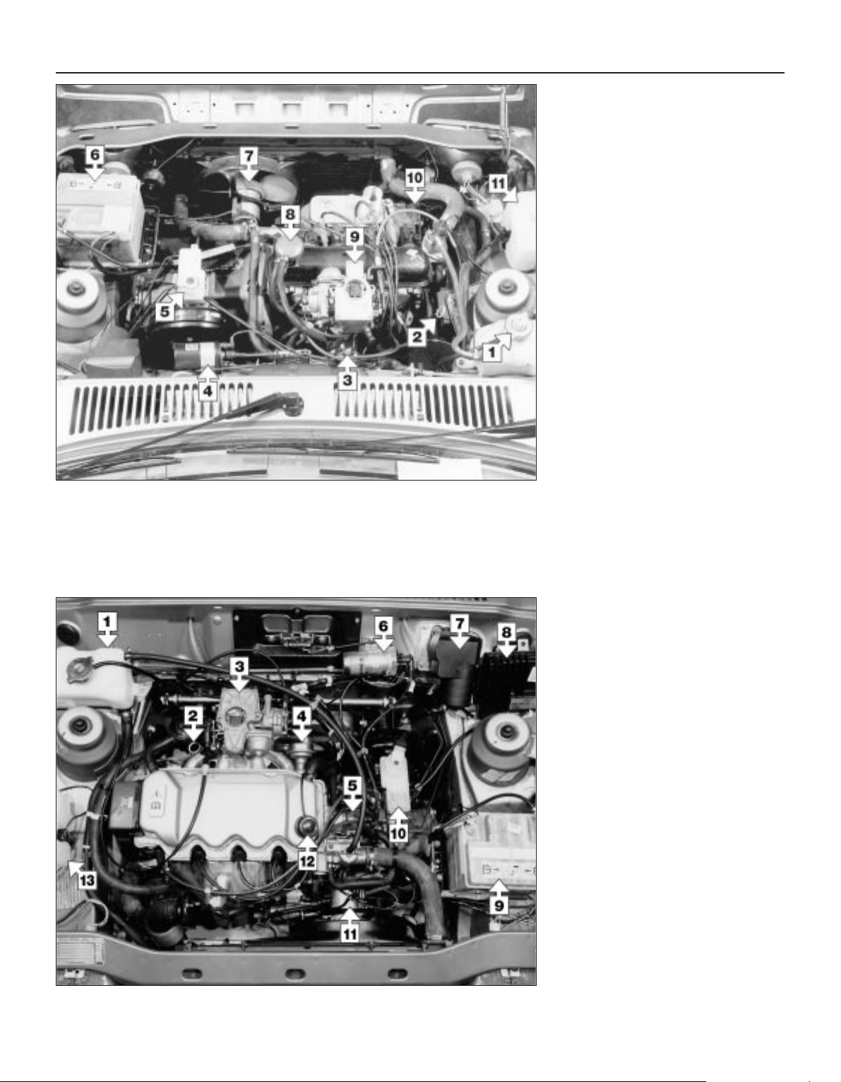
Engine compartment - OHV
1 Coolant expansion tank
2 Engine oil dipstick
3 Oil filter
4 Ignition coil
5 Brake fluid reservoir
6 Battery
7 Cooling fan
8 Oil filler cap
9 Carburettor (air cleaner removed)
10 Alternator
11 Washer reservoir
Engine compartment - CVH
1 Coolant expansion tank
2 Engine oil dipstick
3 Carburettor (air cleaner removed)
4 Fuel pump
5 Distributor
6 Ignition coil
7 Windscreen wiper motor
8 Ignition amplifier module
9 Battery
10 Brake fluid reservoir
11 Cooling fan
12 Oil filler cap
13 Washer reservoir
Page 5
Maintenance - component location 1•5
1
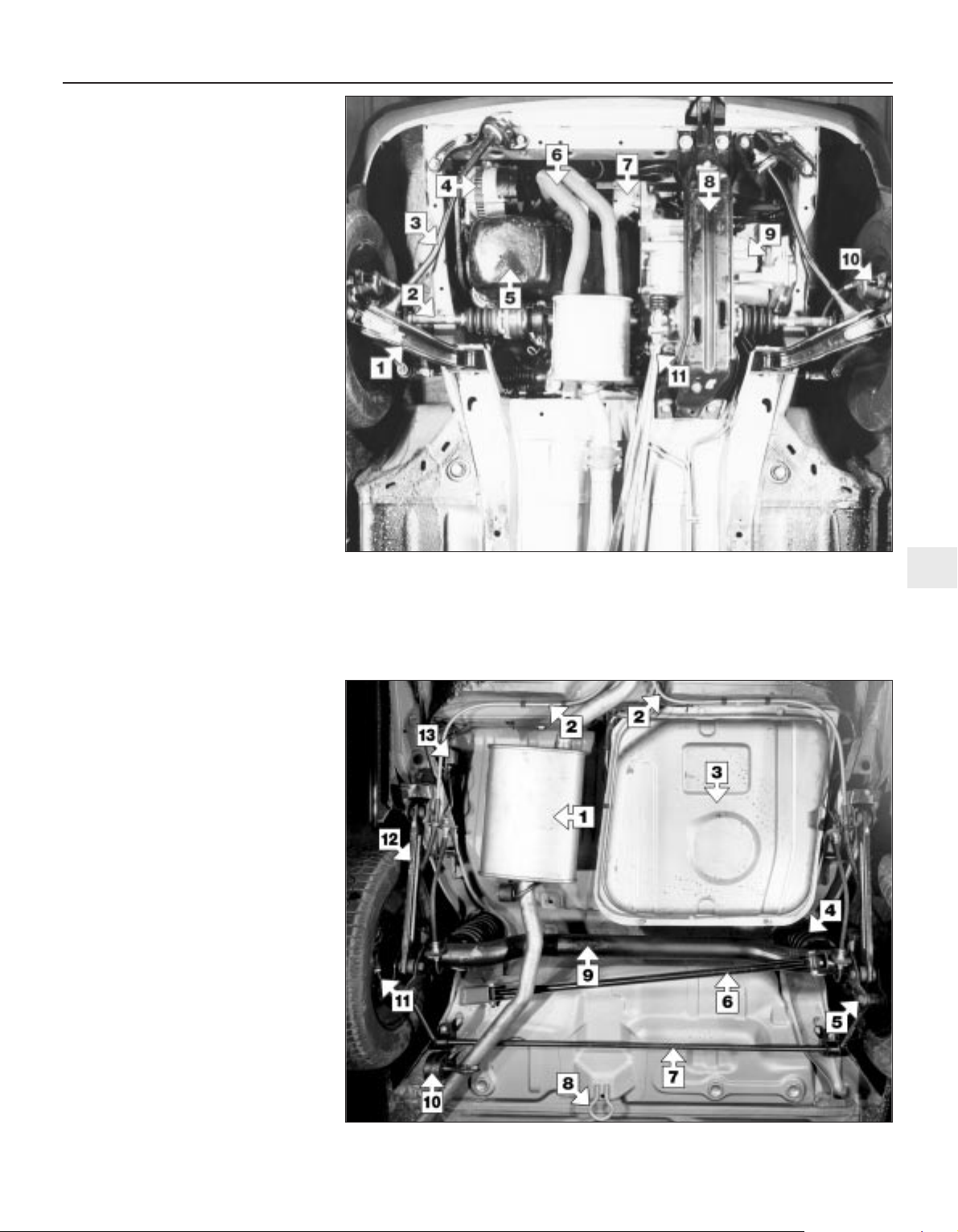
Underside view of car at rear
1 Rear silencer
2 Brake secondary cable
3 Fuel tank
4 Suspension coil spring
5 Shock absorber lower mounting
6 Panhard rod
7 Anti-roll bar (certain models only)
8 Towing eye
9 Axle beam
10 Exhaust system mounting
11 Handbrake adjustment check plunger
12 Suspension trailing arm
13 Brake pressure control valve
Underside view of car at front - CVH
1 Suspension arm
2 Driveshaft
3 Tie-bar
4 Alternator
5 Sump
6 Exhaust
7 Starter motor
8 Engine/gearbox bearer
9 Gearbox
10 Disc brake caliper
11 Gearchange rod and stabilizer rod
Page 6

1 Introduction
This Chapter is designed to help the home
mechanic maintain his/her vehicle for safety,
economy, long life and peak performance.
The Chapter contains a master
maintenance schedule, followed by Sections
dealing specifically with each task in the
schedule. Visual checks, adjustments,
component renewal and other helpful items
are included. Refer to the accompanying
illustrations of the engine compartment and
the underside of the vehicle for the locations
of the various components.
Servicing your vehicle in accordance with
the mileage/time maintenance schedule and
the following Sections will provide a planned
maintenance programme, which should result
in a long and reliable service life. This is a
comprehensive plan, so maintaining some
items but not others at the specified service
intervals, will not produce the same results.
As you service your vehicle, you will
discover that many of the procedures can and should - be grouped together, because of
the particular procedure being performed, or
because of the close proximity of two
otherwise-unrelated components to one
another. For example, if the vehicle is raised
for any reason, the exhaust can be inspected
at the same time as the suspension and
steering components.
The first step in this maintenance
programme is to prepare yourself before the
actual work begins. Read through all the
Sections relevant to the work to be carried
out, then make a list and gather together all
the parts and tools required. If a problem is
encountered, seek advice from a parts
specialist, or a dealer service department.
2 Intensive maintenance
If, from the time the vehicle is new, the
routine maintenance schedule is followed
closely, and frequent checks are made of fluid
levels and high-wear items, as suggested
throughout this manual, the engine will be
kept in relatively good running condition, and
the need for additional work will be minimised.
It is possible that there will be times when
the engine is running poorly due to the lack of
regular maintenance. This is even more likely
if a used vehicle, which has not received
regular and frequent maintenance checks, is
purchased. In such cases, additional work
may need to be carried out, outside of the
regular maintenance intervals.
If engine wear is suspected, a compression
test will provide valuable information
regarding the overall performance of the main
internal components. Such a test can be used
as a basis to decide on the extent of the work
to be carried out. If, for example, a
compression test indicates serious internal
engine wear, conventional maintenance as
described in this Chapter will not greatly
improve the performance of the engine, and
may prove a waste of time and money, unless
extensive overhaul work is carried out first.
The following series of operations are those
most often required to improve the
performance of a generally poor-running
engine:
Primary operations
a) Clean, inspect and test the battery
b) Check all the engine-related fluids
c) Check the condition and tension of the
auxiliary drivebelt
d) Renew the spark plugs
e) Inspect the distributor cap and HT leads -
as applicable
f) Check the condition of the air cleaner
filter element, and renew if necessary
g) Renew the fuel filter (if fitted)
h) Check the condition of all hoses, and
check for fluid leaks
i) Check the idle speed and mixture settings
- as applicable
If the above operations do not prove fully
effective, carry out the following secondary
operations:
Secondary operations
a) Check the charging system
b) Check the ignition system
c) Check the fuel system
d) Renew the distributor cap and rotor arm -
as applicable
e) Renew the ignition HT leads - as applicable
3 Engine oil and filter renewal
1
1 Frequent oil and filter changes are the most
important preventative maintenance
procedures which can be undertaken by the
DIY owner. As engine oil ages, it becomes
diluted and contaminated, which leads to
premature engine wear.
2 Before starting this procedure, gather
together all the necessary tools and materials.
Also make sure that you have plenty of clean
rags and newspapers handy, to mop up any
spills. Ideally, the engine oil should be warm,
as it will drain better, and more built-up
sludge will be removed with it. Take care,
however, not to touch the exhaust or any
other hot parts of the engine when working
under the vehicle. To avoid any possibility of
scalding, and to protect yourself from
possible skin irritants and other harmful
contaminants in used engine oils, it is
advisable to wear gloves when carrying out
this work. Access to the underside of the
vehicle will be greatly improved if it can be
raised on a lift, driven onto ramps, or jacked
up and supported on axle stands (see
“Jacking and vehicle support”). Whichever
method is chosen, make sure that the vehicle
remains level, or if it is at an angle, so that the
drain plug is at the lowest point.
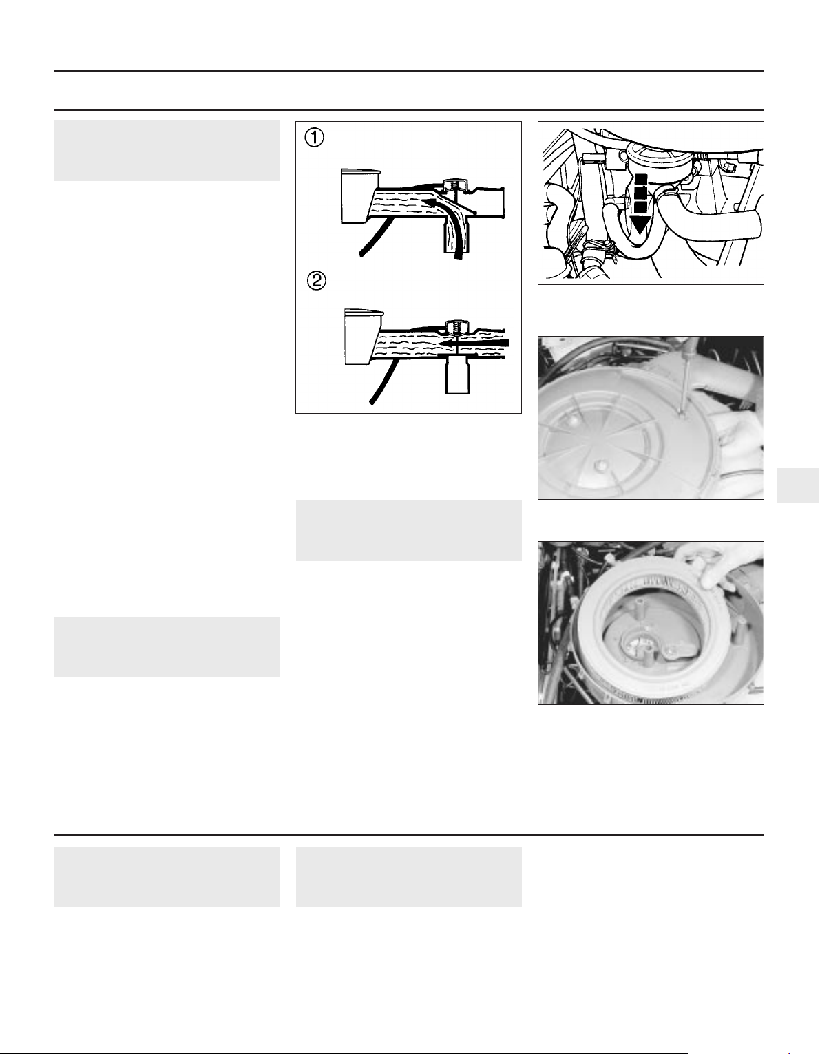
3 Slacken the drain plug about half a turn (see
illustration). Position the draining container
under the drain plug, then remove the plug
completely. If possible, try to keep the plug
pressed into the sump while unscrewing it by
hand the last couple of turns. Recover the
sealing washer from the drain plug.
4 Allow some time for the old oil to drain,
noting that it may be necessary to reposition
the container as the oil flow slows to a trickle.
5 After all the oil has drained, wipe off the
drain plug with a clean rag. Check the sealing
washer for condition, and renew it if
necessary. Clean the area around the drain
plug opening, and refit the plug. Tighten the
plug to the specified torque.
6 Move the container into position under the
oil filter.
7 Using an oil filter removal tool if necessary,
slacken the filter initially, then unscrew it by
hand the rest of the way (see illustration).
Empty the oil from the old filter into the
container, and discard the filter.
8 Use a clean rag to remove all oil, dirt and
sludge from the filter sealing area on the
engine. Check the old filter to make sure that
the rubber sealing ring hasn’t stuck to the
engine. If it has, carefully remove it.
1•6 Maintenance procedures
3.3 Removing the sump drain plug
6000 Mile (10 000 Km) / 6 Month Service
Remove the engine oil drain
plug quickly so that the
stream of oil runs into the
container, not up your sleeve!
Page 7
9 Apply a light coating of clean engine oil to
the sealing ring on the new filter, then screw it
into position on the engine. Tighten the filter
firmly by hand only - do not use any tools.
Wipe clean the filter and sump drain plug.
10 Remove the old oil and all tools from
under the car, then lower the car to the
ground (if applicable).
11 Remove the oil filler cap and withdraw the
dipstick. Fill the engine, using the correct
grade and type of oil (see “Lubricants and
fluids” and “Capacities” in the Specifications).
An oil can spout or funnel may help to reduce
spillage. Pour in half the specified quantity of
oil first, then wait a few minutes for the oil to
fall to the sump. Continue adding oil a small
quantity at a time until the level is up to the
lower mark on the dipstick. Finally, bring the
level up to the upper mark on the dipstick.
Insert the dipstick, and refit the filler cap.
12 Start the engine and run it for a few
minutes; check for leaks around the oil filter
seal and the sump drain plug. Note that there
may be a delay of a few seconds before the oil
pressure warning light goes out when the
engine is first started, as the oil circulates
through the engine oil galleries and the new oil
filter, before the pressure builds up.
13 Switch off the engine, and wait a few
minutes for the oil to settle in the sump once
more. With the new oil circulated and the filter
completely full, recheck the level on the
dipstick, and add more oil as necessary.
14 Dispose of the used engine oil safely.
4 Front and rear brake
pad/shoe check
1
1 Firmly apply the handbrake, then jack up
the front and rear of the car and support it
securely on axle stands (see “Jacking and
vehicle support”).
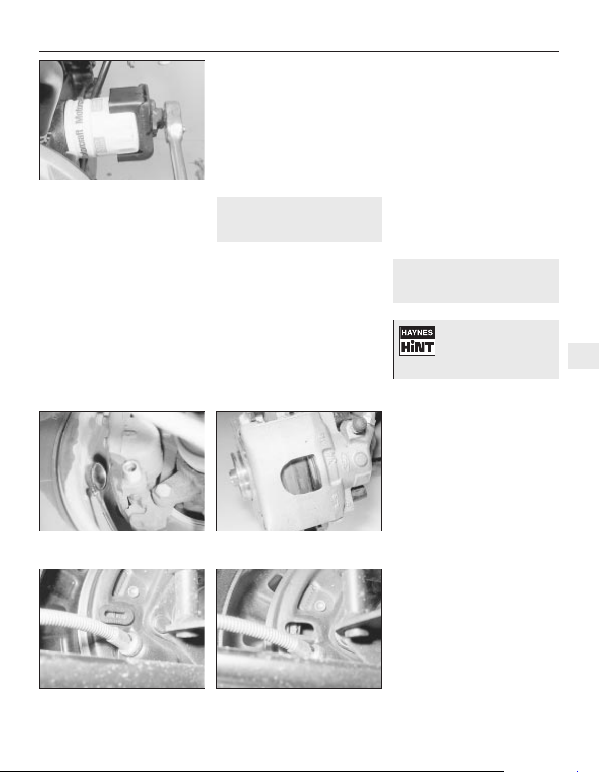
2 For a quick check, the front brake disc pads
can be inspected without removing the front
wheels by inserting a mirror between each
caliper and roadwheel (see illustrations). If
any one pad is worn down to the minimum
specified thickness, all four pads (on both
front wheels) must be renewed.
3 For a comprehensive check, the brake disc
pads should be removed and cleaned. The
operation of the caliper can then also be
checked, and the condition of the brake discs
can be fully examined on both sides. Refer to
Chapter 9 for further information.
4 The rear brake shoe friction material can be
inspected for wear without removing the
roadwheels. Working beneath the vehicle,
prise the plug from the brake backplate and
using an inspection lamp or torch, check that
the friction material thickness is not less than
the minimum given in the Specifications (see
illustrations). If any one of the shoes has
worn below the specified limit, the shoes must
be renewed as an axle set (4 shoes).
5 At the same interval, check the function of
the brake fluid level warning light. Chock the
wheels, release the handbrake and switch on
the ignition. Unscrew and raise the brake fluid
reservoir cap whilst an assistant observes the
warning light: it should come on as the level
sensor is withdrawn from the fluid. Refit the
cap.
6 On completion, refit the wheels and lower
the car to the ground.
5 Fluid leak check
1
1 Visually inspect the engine joint faces,
gaskets and seals for any signs of water or oil
leaks. Pay particular attention to the areas
around the rocker cover, cylinder head, oil
filter and sump joint faces. Bear in mind that
over a period of time some very slight
seepage from these areas is to be expected
but what you are really looking for is any
indication of a serious leak. Should a leak be
found, renew the offending gasket or oil seal
by referring to the appropriate Chapter(s) in
this manual.
2 Similarly, check the transmission for oil
leaks, and investigate and rectify and
problems found.
3 Check the security and condition of all the
engine related pipes and hoses. Ensure that
all cable-ties or securing clips are in place and
in good condition. Clips which are broken or
missing can lead to chafing of the hoses,
pipes or wiring which could cause more
serious problems in the future.
4 Carefully check the condition of all coolant,
fuel and brake hoses. Renew any hose which
is cracked, swollen or deteriorated. Cracks
will show up better if the hose is squeezed.
Pay close attention to the hose clips that
secure the hoses to the system components.
Hose clips can pinch and puncture hoses,
resulting in leaks. If wire type hose clips are
used, it may be a good idea to replace them
with screw-type clips.
5 With the vehicle raised, inspect the fuel
tank and filler neck for punctures, cracks and
Every 6000 miles or 6 months 1•7
4.2b Inspect the disc brake pads through
the caliper housing aperture
4.4b . . . to check the rear brake linings for
wear
4.4a Remove the inspection plug from the
rear brake backplate . . .
4.2a Using a mirror to check disc brake
pads for wear
3.7 Removing the engine oil filter with a
clamp wrench
1
Leaks in the cooling system
will usually show up as
white or rust-coloured
deposits around the area
adjoining the leak.
Page 8
other damage. The connection between the
filler neck and tank is especially critical.
Sometimes a rubber filler neck or connecting
hose will leak due to loose retaining clamps or
deteriorated rubber.
6 Similarly, inspect all brake hoses and metal
pipes. If any damage or deterioration is
discovered, do not drive the vehicle until the
necessary repair work has been carried out.
Renew any damaged sections of hose or pipe.
7 Carefully check all rubber hoses and metal
fuel lines leading away from the petrol tank.
Check for loose connections, deteriorated
hoses, crimped lines and other damage. Pay
particular attention to the vent pipes and
hoses which often loop up around the filler
neck and can become blocked or crimped.
Follow the lines to the front of the vehicle
carefully inspecting them all the way. Renew
damaged sections as necessary.
8 From within the engine compartment,
check the security of all fuel hose attachments
and pipe unions, and inspect the fuel hoses
and vacuum hoses for kinks, chafing and
deterioration.
9 Check the condition of all exposed wiring
harnesses.
6 Seat belt check
1
1 Periodically check the belts for fraying or
other damage. If evident, renew the belt.
2 If the belts become dirty, wipe them with a
damp cloth using a little detergent only.
3 Check the tightness of the anchor bolts and
if they are ever disconnected, make quite sure
that the original sequence of fitting of
washers, bushes and anchor plates is
retained.
7 Exhaust system check
1
With the vehicle raised on a hoist or
supported on axle stands (see “Jacking and
vehicle support”), check the exhaust system
for signs of leaks, corrosion or damage and
check the rubber mountings for condition and
security (see illustration). Where damage or
corrosion are evident, renew the system
complete or in sections, as applicable, using
the information given in Chapter 4.
8 Roadwheel security check
1
With the wheels on the ground, slacken
each wheel bolt by a quarter turn, then
retighten it immediately to the specified
torque.
9 Choke adjustment check
2
On models equipped with carburettors of
Ford manufacture, refer to Chapter 4, Section
9 and check that the choke is adjusted within
the stated parameters.
10 Engine idle speed check
3
Note: Refer to the precautions given in
Section 1 of Chapter 4 before proceeding.
Note: Before carrying out any carburettor
adjustments, ensure that the ignition timing
and spark plug gaps are set as specified. To
carry out this adjustment, an accurate
tachometer will be required.
Ford 1V carburettor
1 Ensure that the air cleaner is correctly fitted,
and that all vacuum hoses and pipes are
securely connected and free from restrictions,
then run the engine until it is at normal
operating temperature.
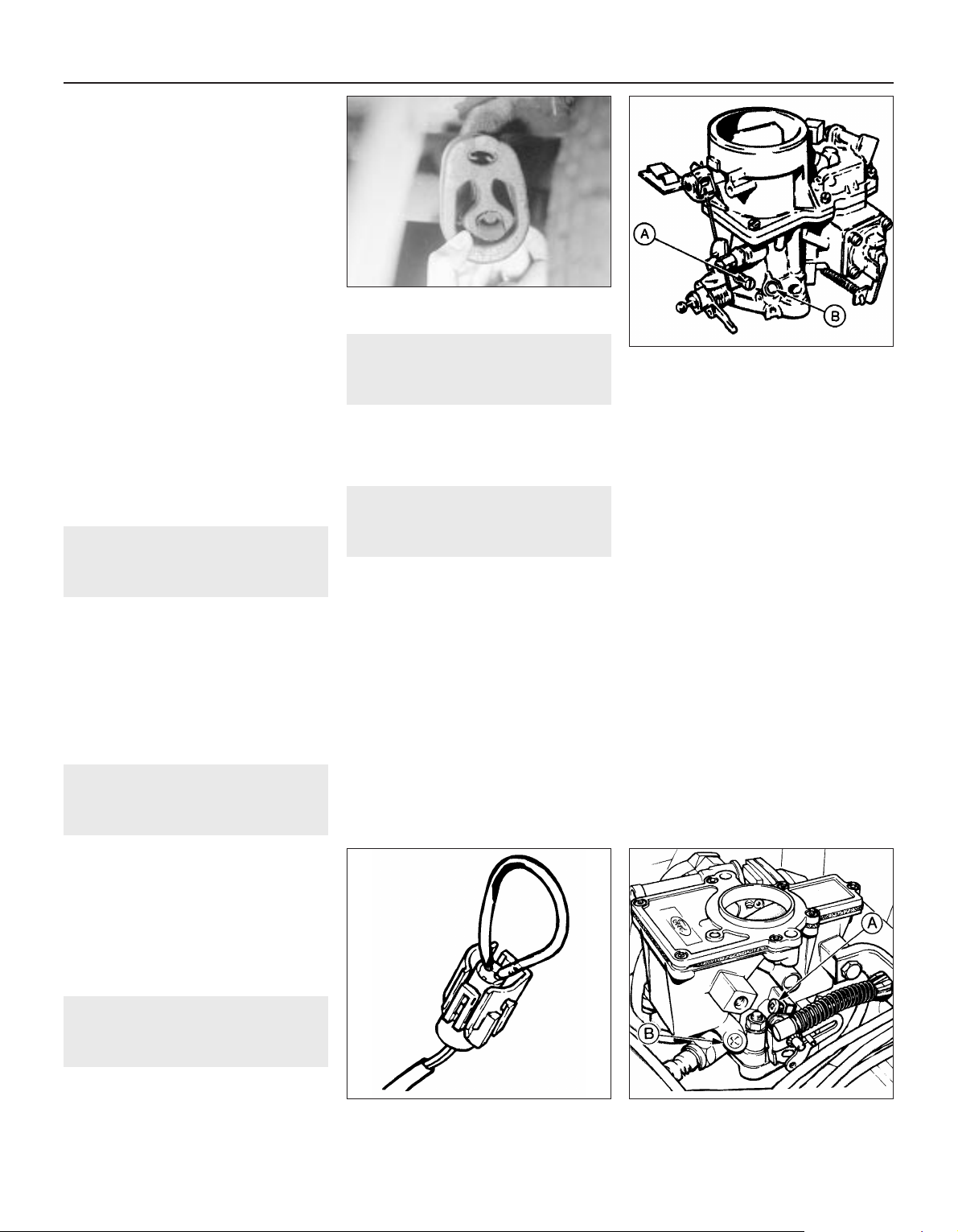
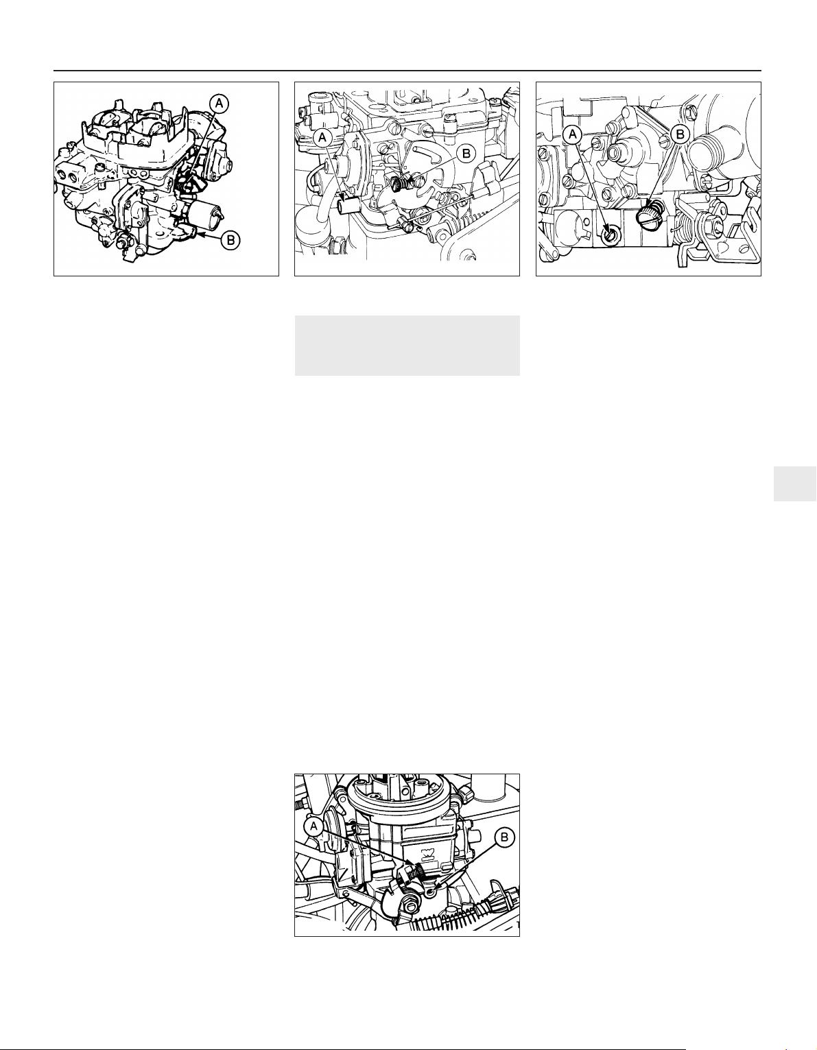
2 With the engine at normal operating
temperature, adjust the idle speed screw (see
illustration) to obtain the specified idle speed,
using a tachometer to ensure accuracy.
Ford VV carburettor
3 This procedure must be carried out with the
radiator cooling fan in operation. To keep the
fan running during the adjustment procedure,
disconnect the wiring multi-plug from the
thermal switch (located in the thermostat
housing) and bridge the two contacts in the
plug with a short length of wire (see
illustration). Disconnect the wire and refit the
multi-plug on completion of the adjustments.
Make sure that the engine and ignition are
switched off when connecting and
disconnecting the bridging wire.
4 Ensure that the air cleaner is correctly fitted,
and that all vacuum hoses and pipes are
securely connected and free from restrictions,
then run the engine until it is at normal
operating temperature.
5 With the engine at normal operating
temperature, connect a tachometer in
accordance with the manufacturer’s
instructions.
6 Start the engine, run it at 3000 rpm for 30
seconds and then let it idle. Turn the idle
speed adjusting screw in or out as necessary
to bring the speed to that given in the Specifications (see illustration).
1•8 Every 6000 miles or 6 months
7.1 Inspect the exhaust system rubber
mounting
10.3 Temporary bridging wire in cooling
fan thermal switch multi-plug
10.6 Ford VV carburettor idle speed screw
(A) and mixture screw (B)
10.2 Ford 1V carburettor idle speed screw
(A) and mixture screw (B)
Page 9
Weber 2V carburettor
7 Refer to the information relating to the Ford
1V carburettor for details, and to the
accompanying illustration (see illustration)
for the adjusting screws. Ensure that the
engine fan is operating by pulling the two
wires from the sensor, and connecting the
wires with a jumper lead.
Weber 2V DFTM
8 Before carrying out this adjustment, ensure
that the air cleaner is correctly fitted and that
all vacuum hoses and pipes are securely
connected and free from restrictions. Run the
engine until it is at normal operating
temperature.
9 The cooling fan must be kept running
during the adjustment procedure. To do this,
disconnect the wiring multi-plug from the
thermal switch (located in the thermostat
housing) and bridge the two contacts in the
plug with a short length of wire.
10 Start the engine and turn the idle speed
adjustment screw (see illustration) to obtain
the specified idle speed, using a tachometer
to ensure accuracy.
Weber 2V TLD carburettor
11 Refer to the information relating to the
Weber 2V DFTM carburettor for details, and to
the accompanying illustration (see illustration)
for the adjusting screws.
Weber (1V) TLM carburettor
12 Before carrying out this adjustment,
ensure that the air cleaner is correctly fitted
and that all vacuum hoses and pipes are
securely connected and free from restrictions.
Run the engine until it is at normal operating
temperature.
13 Connect a reliable tachometer to the
engine in accordance with the manufacturer’s
instructions.
14 Increase the engine speed to 3000 rpm
and hold it at this speed for 30 seconds, then
allow the engine to idle. Adjust the idle speed
to within the specified range by turning the
idle speed screw (see illustration).
11 Mixture adjustment check
3
Note: Refer to the precautions given in
Section 1 of Chapter 4 before proceeding.
Note: Before carrying out any carburettor
adjustments, ensure that the ignition timing
and spark plug gaps are set as specified. To
carry out the adjustments an accurate
tachometer and an exhaust gas analyser (CO
meter) will be required. Adjustment of the idle
mixture setting should not be attempted in
territories where this may cause a violation of
exhaust emission regulations. Where these
regulations are less stringent the following
procedures may be used.
Ford 1V carburettor
1 Ensure that the air cleaner is correctly fitted
and that all vacuum hoses and pipes are
securely connected and free from restrictions,
then run the engine until it is at normal
operating temperature.
2 Using a small screwdriver, prise out the
tamperproof plug (if fitted) over the idle
mixture screw.
3 Connect the CO meter and tachometer
according to the manufacturer’s instructions.
4 Adjust the idle speed to the specified setting.
5 Run the engine at 3000 rpm for 30 seconds
to clear the inlet manifold of excess fuel.
Repeat this operation every 30 seconds
during the adjustment procedure.
6 Turn the idle mixture screw in the desired
direction to achieve the fastest possible
engine speed consistent with smooth, even
running or the correct specified CO reading
on the meter scale.
7 If necessary, readjust the idle speed setting
on completion. Fit a new tamperproof plug to
the mixture screw.
Ford VV carburettor
8 This procedure must be carried out with the
radiator cooling fan in operation. To keep the
fan running during the adjustment procedure,
disconnect the wiring multi-plug from the
thermal switch (located in the thermostat
housing) and bridge the two contacts in the
plug with a short length of wire. Disconnect
the wire and refit the multi-plug on completion
of the adjustments. Make sure that the engine
and ignition are switched off when connecting
and disconnecting the bridging wire.
9 To adjust the mixture accurately, connect a
CO (exhaust gas) analyser and a tachometer
in accordance with the manufacturer’s
instructions.
10 Ensure that the air cleaner is correctly
fitted and that all vacuum hoses and pipes are
securely connected and free from restrictions,
then run the engine until it is at normal
operating temperature.
11 Using a thin, sharp screwdriver, prise out
the tamperproof plug which covers the
mixture screw.
12 Start the engine and run it at 3000 rpm for
30 seconds, then allow it to return to idle. Turn
the mixture screw in (weak) or out (rich) until
the CO level is within the specified range as
indicated on the analysing equipment. The
adjustment must be carried out within 30
seconds; otherwise, again increase the engine
speed for 30 seconds before continuing with
the adjustment.
13 Once the mixture is correct, adjust the idle
speed then recheck the mixture.
14 Switch off the engine and remove the
tachometer and the exhaust gas analyser. Fit
a new tamperproof plug to the mixture screw.
15 In the absence of a suitable exhaust gas
analyser, an approximate setting of the
mixture screw may be made by turning the
screw inwards (engine idling) until the idle
speed just begins to drop. Unscrew the screw
Every 6000 miles or 6 months 1•9
10.11 Weber 2V TLD carburettor mixture
screw (A) and idle speed screw (B)
10.14 Weber (1V) TLM carburettor idle
speed screw (A) and mixture screw (B)
10.10 Weber 2V DFTM carburettor mixture
screw (A) and idle speed screw (B)
10.7 Weber 2V carburettor idle speed
screw (A) and mixture screw (B)
1
Page 10
the smallest amount necessary to achieve
smooth idle. The CO level of the exhaust gas
should be checked by your dealer at the
earliest opportunity and further adjustment
carried out as may be necessary.
Weber 2V carburettor
16 Refer to the information relating to the
Ford 1V carburettor for details. Ensure that
the engine fan is operating by pulling the two
wires from the sensor, and connecting the
wires with a jumper lead.
Weber 2V DFTM carburettor
17 The cooling fan must be kept running
during the adjustment procedure. To do this,
disconnect the wiring multi-plug from the
thermal switch (located in the thermostat
housing) and bridge the two contacts in the
plug with a short length of wire.
18 Ensure that the air cleaner is correctly
fitted and that all vacuum hoses and pipes are
securely connected and free from restrictions,
then run the engine until it is at normal
operating temperature.
19 Using a small screwdriver, prise out the
tamperproof plug (if fitted) over the idle
mixture screw.
20 Connect the CO meter and tachometer
according to the manufacturer’s instructions.
21 Adjust the idle speed to the correct setting.
22 Run the engine at 3000 rpm for 30
seconds to clear the inlet manifold of excess
fuel. Repeat this operation every 30 seconds
during the adjustment procedure.
23 Turn the idle mixture screw in the desired
direction to achieve the fastest possible
engine speed consistent with smooth, even
running; or the correct specified CO reading
on the meter scale.
24 If necessary, readjust the idle speed
setting. Refit the cooling fan multi-plug and fit
a new tamperproof plug.
Weber 2V TLD carburettor
25 Refer to the information relating to the
Weber 2V DFTM carburettor for details.
Weber (1V) TLM carburettor
26 Ensure that the air cleaner is correctly
fitted and that all vacuum hoses and pipes are
securely connected and free from restrictions,
then run the engine until it is at normal
operating temperature.
27 With the engine at normal operating
temperature, connect a tachometer and
exhaust gas analyser in accordance with the
manufacturer’s instructions.
28 Prise out the tamperproof plug from the
mixture screw hole in the throttle valve block.
29 Wait for the radiator cooling fan to
operate, then raise the engine speed to 3000
rpm, hold it at this speed for 30 seconds,
return to idle and check the exhaust CO level
on the exhaust gas analyser. If it is not as
specified, turn the mixture screw (clockwise to
weaken) and repeat the checking procedure.
30 On completion, fit a new tamperproof
plug.
12 Spark plug check
1
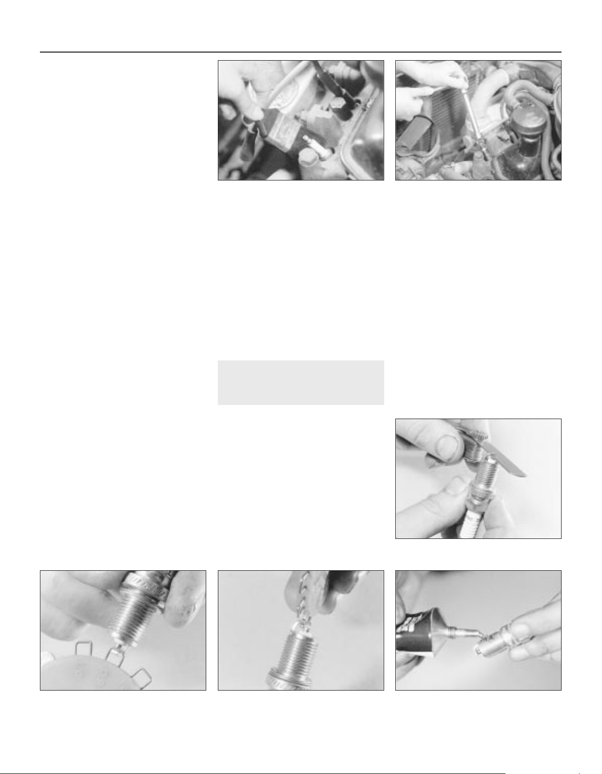
1 Pull the HT lead from each plug by grasping
the end connector. Clean around each spark
plug (see illustration). Remove each plug
(see illustration) and check its electrode gap,
which should be within the limits stated in
Specifications.
2 To adjust the gap, bend the outer electrode
with a proper spark plug gapping tool.
Recheck the gap using feeler blades or wire
gauges (see illustrations).
3 Note that the correct functioning of each
plug is vital for the correct running and
efficiency of the engine. It is essential that the
plugs fitted are appropriate for the engine and
the suitable type is specified at the beginning
of this Chapter. Spark plug cleaning is rarely
necessary and should not be attempted unless
specialised equipment is available as damage
can easily be caused to the firing ends.
4 The appearance of a removed spark plug
can give some indication of the condition or
state of tune of the engine, but as modern
engines run on a weaker fuel/air mixture in
order to conform to current emission control
regulations, a rather whiter appearance of the
spark plug electrode area must be expected
than was the case on older cars. As the
mixture control is preset during production, a
black appearance of the plug electrode will
normally be due to oil passing worn piston
rings or valve stem oil seals, unless the
carburettor has been tampered with.
5 When installing the plugs use a long reach
socket, apply a little grease to the threads of the
plugs (see illustration)and tighten them only to
the specified torque wrench setting. Overtightening may damage the plug or its seat.
1•10 Every 6000 miles or 6 months
12.1a Clean around each spark plug . . .
12.2a Measuring a spark plug electrode
gap with a feeler blade
12.5 Lightly grease the spark plug threads
before fitting
12.2c Adjusting a spark plug electrode
gap with a special tool
12.2b Measuring a spark plug electrode
gap with a wire gauge
12.1b . . . before using a socket to remove
the spark plugs
Page 11
13 HT lead, distributor cap and
ignition circuit check
1
1 Clean each HT lead by wiping along its
length with a fuel-moistened cloth and inspect
it for damage.
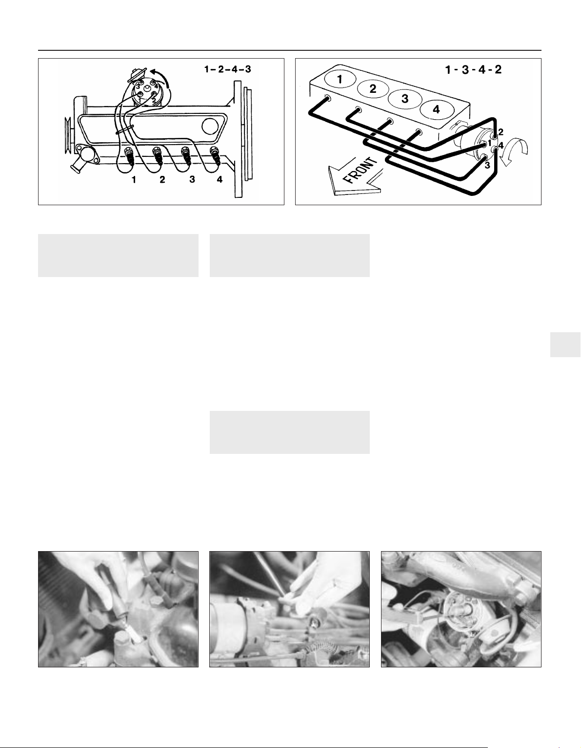
2 Note the fitted position of each lead before
disconnection (see illustrations). When
removing a lead from a spark plug or the HT
coil, pull the lead off by its rubber connector
(see illustration).
3 The socket contacts on the distributor cap
should be cleaned if they appear corroded
(see illustration). A smear of petroleum jelly
(not grease) applied to the ferrule on the end
of the HT lead will help to prevent corrosion.
4 Remove the distributor cap and rotor arm.
5 Examine the rotor arm and inside of the
distributor cap . If the contacts are corroded
or are excessively burnt, or if the carbon
centre contact in the cap is worn away, renew
the cap or rotor, as necessary. Check
carefully for hairline cracks and signs of
arcing. Make sure that the HT leads are
reinstalled in their correct firing order.
6 Check that all HT and LT electrical leads are
correctly routed and clear of all moving or hot
engine components. Ensure that all lead
connections are secure and where applicable,
protected.
14 Hinge and lock check and
lubrication
1
1 Work around the vehicle, and lubricate the
bonnet, door and tailgate hinges with a light
machine oil.
2 Lightly lubricate the bonnet release
mechanism and exposed sections of inner
cable with a smear of grease.
3 Check the security and operation of all
hinges, latches and locks, adjusting them
where required.
4 Check the condition and operation of the
tailgate struts, renewing them if either is
leaking or is no longer able to support the
tailgate securely when raised.
15 Ignition timing and contact
breaker gap (dwell angle)
check - OHV engines
3
Contact breaker gap (dwell
angle)
1 Access to the distributor is improved by
removing the air cleaner unit.
2 Prise down the distributor cap retaining
clips or remove the securing screws, as
appropriate. Remove the distributor cap and
rotor.
3 Apply a spanner to the crankshaft pulley
bolt and turn the crankshaft until the
distributor points are fully open, with the heel
of the cam follower on the highest point of
one of the lobes of the cam.
4 Using feeler blades, check the points gap
(see illustration). If the blade is not a sliding
fit, release the screw at the fixed contact so
that the contact will move and adjust the gap
to that specified. Retighten the screw, refit the
rotor and cap. Take care not to contaminate
the points with oil from the feeler blades.
5 This method of adjustment should be
regarded as second best as on modern
engines, setting the points gap is usually
carried out by measuring the dwell angle.
6 The dwell angle is the number of degrees
through which the distributor cam turns
during the period between the instants of
closure and opening of the contact breaker
points. Checking the dwell angle not only
gives a more accurate setting of the contact
breaker gap, but this method also evens out
any variations in the gap which could be
caused by pitting of the points, wear in the
distributor shaft or its bushes, or difference in
height of any of the cam peaks.
7 The dwell angle should be checked with a
dwell meter connected in accordance with the
maker’s instructions. Refer to the Specifications for the correct dwell angle. If the dwell
angle is too large, increase the points gap. If it
is too small, reduce the gap.
Every 6000 miles or 6 months 1•11
13.2c Pull the HT lead connector - not the
lead
15.4 Checking the contact breaker points
gap using a feeler blade
13.3 Inspect each HT lead end ferrule for
corrosion
13.2b HT lead connections - CVH engines13.2a HT lead connections - OHV engines
1
Page 12
8 The dwell angle should always be adjusted
before checking and adjusting the ignition
timing, as follows:
Ignition timing
9 Before checking the timing, check and
adjust the dwell angle with the engine at
normal operating temperature.
10 Increase the contrast of the notch in the
crankshaft pulley and the appropriate mark on
the timing index (refer to Specifications) by
applying quick-drying white paint (see
illustration).
11 Connect a timing light (stroboscope) in
accordance with the manufacturer’s
instructions.
12 Start the engine and allow it to idle.
13 Disconnect the vacuum pipe from the
distributor and plug the pipe with a piece of rod.
14 If the timing light is now directed at the
engine timing marks, the pulley notch will
appear to be stationary and opposite the
specified mark on the scale. If the marks are
not in alignment, release the distributor clamp
pinch-bolt (see illustration) and turn the
distributor in whichever direction is necessary
to align the marks.
15 Retighten the pinch-bolt, switch off the
engine, remove the timing light and reconnect
the vacuum pipe.
16 It may now be necessary to check and
adjust the engine idle speed if the distributor
setting has to be varied to any extent.
16 Throttle damper operation
check
2
1 To check the operation of the throttle
damper fitted to models equipped with a Ford
VV carburettor, proceed as follows:
2 Warm up the engine to normal operating
temperature, then switch off. Connect a
tachometer in accordance with the
manufacturer’s instructions. To keep the fan
running during the adjustment procedure,
disconnect the wiring multi-plug from the
thermal switch (located in the thermostat
housing) and bridge the two contacts in the
plug with a short length of wire.
3 Start the engine and increase its speed to
3200 ± 150 rpm by means of the idle speed
adjustment screw. When the speed has
stabilised, switch off the engine.
4 Rotate the secondary throttle lever
clockwise to remove any play between the
primary and secondary throttle levers, but
ensure that the primary lever does not move.
5 Using a feeler blade, unscrew the damper
until a clearance of 0.1 to 0.3 mm exists
between the damper plunger and the
secondary throttle lever (see illustration).
Hold the damper in this position and tighten
the locknut.
6 Start the engine and return the idle speed to
the specified rpm. Disconnect the tachometer
and bridging wire, refit the multi-plug, then
refit the air cleaner.
17 Battery terminal check
1
1 To clean the battery terminals disconnect
them, negative earth first, after having first
removed the cover (where fitted). Use a wire
brush or abrasive paper to clean the
terminals. Bad corrosion should be treated
with a solution of bicarbonate of soda, applied
with an old toothbrush. Do not let this solution
get inside the battery.
2 Coat the battery terminals with petroleum
jelly or a proprietary anti-corrosive compound
before reconnecting them (see illustration).
Reconnect and tighten the positive (live) lead
first, followed by the negative (earth) lead. Do
not overtighten.
18 Engine valve clearance
check - OHV engines
2
1 This operation should be carried out with
the engine cold and the air cleaner, spark
plugs and rocker cover removed.
2 Using a ring spanner or socket on the
crankshaft pulley bolt, turn the crankshaft in a
clockwise direction until No 1 piston is at top
dead centre (TDC) on its compression stroke.
This can be verified by checking that the
pulley and timing cover marks are in
1•12 Every 6000 miles or 6 months
15.10 Ignition timing marks - mechanical
ignition system
A Crankshaft pulley notch
B Timing cover scale
16.5 Setting throttle damper clearance
using a feeler blade (arrowed) -
Ford VV carburettor
17.2 Protect each battery terminal before
reconnection
15.14 Distributor clamp plate pinch-bolt
(arrowed)
12 000 Mile (20 000 Km) / 12 Month Service
To keep corrosion to a
minimum, coat the battery
terminals with petroleum
jelly or a proprietary anti-
corrosive compound.
When checking valve
clearances, it will be easier
to turn the engine by hand if
the spark plugs are removed
but take care not to allow dirt to enter
the spark plug holes.
Warning: Before carrying out
any work on the vehicle battery,
read through the precautions
given in “Safety first!” at the
beginning of this manual.
Page 13
alignment and that the valves of No 4 cylinder
are rocking. When the valves are rocking, this
means that the slightest rotation of the
crankshaft pulley in either direction will cause
one rocker arm to move up and the other to
move down.
3 Numbering from the thermostat housing
end of the cylinder head, the valves are
identified as follows:
Valve No Cylinder no
1 - Exhaust 1
2 - Inlet 1
3 - Exhaust 2
4 - Inlet 2
5 - Exhaust 3
6 - Inlet 3
7 - Exhaust 4
8 - Inlet 4
4 Adjust the valve clearances by following the
sequence given in the following table. Turn
the crankshaft pulley 180° (half a turn) after
adjusting each pair:
Valves rocking Valves to adjust
7 and 8 1 (Exhaust), 2 (Inlet)
5 and 6 3 (Exhaust), 4 (Inlet)
1 and 2 7 (Exhaust), 8 (Inlet)
3 and 4 5 (Exhaust), 6 (Inlet)
5 The clearances for the inlet and exhaust
valves are different (see Specifications). Use a
feeler blade of the appropriate thickness to
check each clearance between the end of the
valve stem and the rocker arm. The blade
should be a stiff sliding fit. If it is not, turn the
adjuster bolt with a ring spanner. These bolts
are of stiff thread type and require no locking
nut. Turn the bolt clockwise to reduce the
clearance and anti-clockwise to increase it
(see illustration).
6 Refit the rocker cover, spark plugs and air
cleaner on completion of adjustment.
19 Handbrake check
2
Pre-September 1985 models
1 Adjustment of the handbrake is normally
automatic by means of the self-adjusting
mechanism working on the rear brake shoes.
2 However, due to cable stretch, checking of
the handbrake adjustment is recommended.
Adjustment must be carried out if the
movement of the lever becomes excessive
(more than six notches). Proceed as follows:
3 Chock the front wheels then fully release
the handbrake.
4 Raise and support the vehicle at the rear
with safety stands.
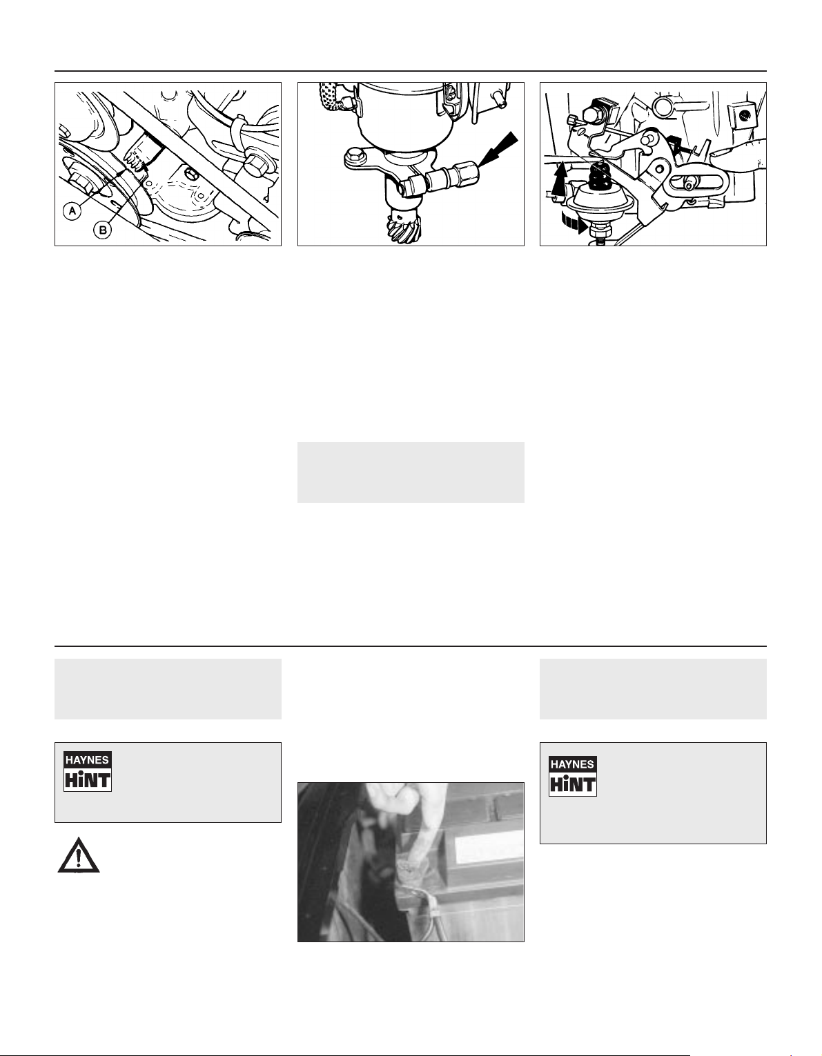
5 On adjustment check that the plunger
protrudes from each rear brake backplate
(see illustration), their respective length of
movement indicating the handbrake
adjustment condition. Before checking their
movement (stroke) length, firmly apply the
footbrake to ensure that the automatic
adjuster mechanism is fully actuated.
6 Now check the plunger stroke movement. If
the total movement of both sides added
together is between 0.5 and 3.0 mm then
adjustment is satisfactory. This should give
three to six clicks (notches) of handbrake
application movement. If there is no
measurable plunger movement or if the total
measurement exceeds that specified adjust
as follows.
7 Loosen the handbrake cable locknut, then
rotate the adjuster sleeve (see illustration) so
that the plungers can just rotate and the total
movement of both plungers is as specified
above.
8 Hand tighten the locknut against the sleeve
so that two engagement clicks are felt, then
further tighten another two clicks using a
suitable wrench.
Models from September 1985
9 Proceed as above, noting that since
September 1985 a locking pin has been fitted
to the cable adjuster abutment bracket to lock
the adjuster sleeve and locknut together.
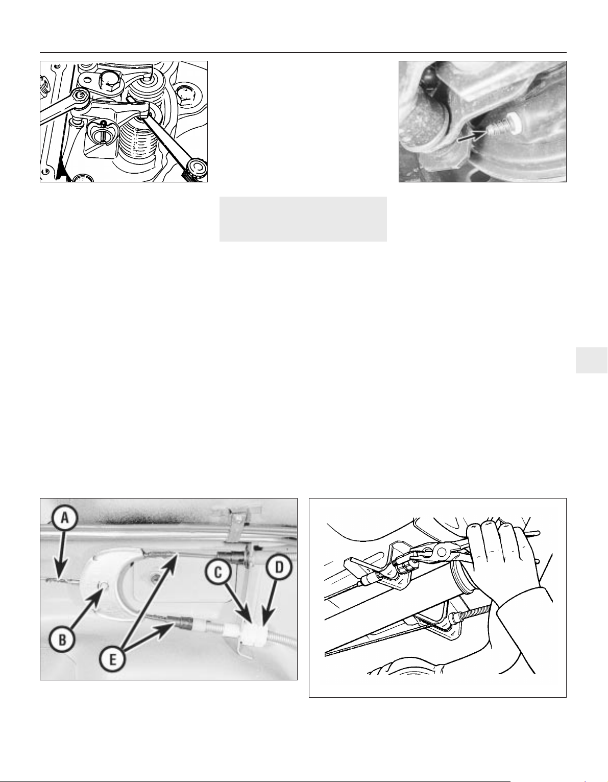
10 Should it be necessary to adjust the
cable, the locking pin must be removed by
pulling it out using pliers (see illustration).
After adjustment a new nylon locking pin must
be used and can be fitted by carefully tapping
it into place.
Every 12 000 miles or 12 months 1•13
19.10 Removing the handbrake cable adjuster locking pin
19.7 Handbrake cable assembly
A Primary cable
B Equaliser
C Adjuster sleeve
D Locknut
E Secondary cable
19.5 Handbrake adjustment indicator
plunger
18.5 Adjusting a valve clearance - OHV
1
Page 14
20 Auxiliary drivebelt check
2
Inspection
1 Check the full length of the drivebelt for
cracks and deterioration. It will be necessary
to turn the engine in order to check that
portion of the drivebelt is in contact with the
pulleys.
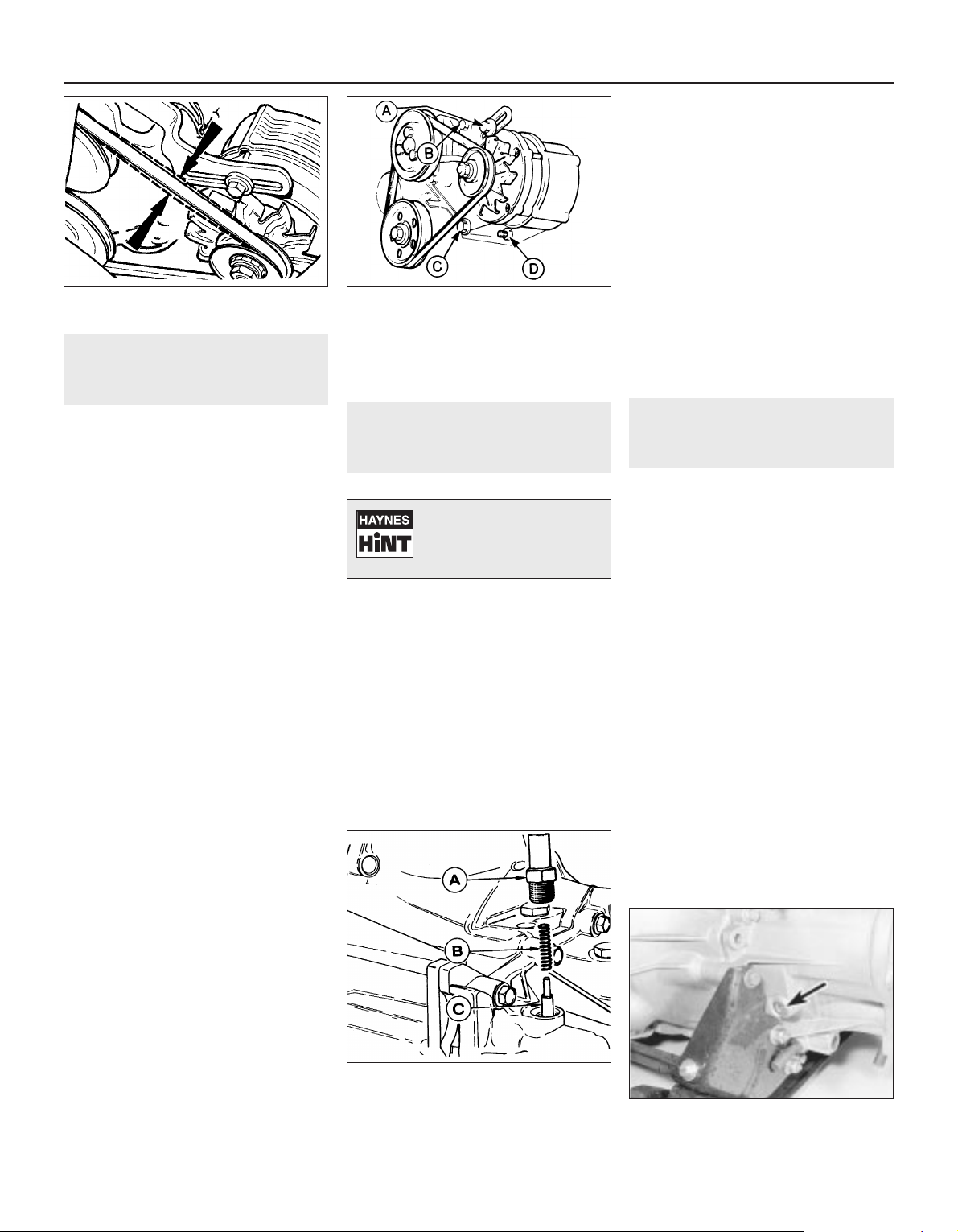
2 Check that the total deflection of the
auxiliary drivebelt is 4.0 mm at the mid point
of its longest run (see illustration).
3 Note that if the belt is too slack, it will slip
and soon become glazed or burnt and the
coolant pump (OHV) and alternator will not
perform correctly, with consequent
overheating of the engine and low battery
charge. If the belt is too tight, the bearings in
the alternator and/or coolant pump will soon
be damaged.
4 If necessary, renew or tension the belt as
follows:
Renewal
5 To remove a belt, slacken the alternator
mounting bolts and the bolts on the adjuster
link (see illustration), push the alternator in
towards the engine and slip the belt from the
pulleys.
6 Fit the belt by slipping it over the pulley rims
while the alternator is still loose on its
mountings. Never be tempted to remove or fit
a belt by prising it over a pulley without
releasing the alternator. Either the pulley will
be damaged or the alternator or coolant pump
will be distorted.
Tensioning
7 To change the belt tension, pull the
alternator away from the engine until the belt
is fairly taut and nip up the adjuster strap bolt.
A little trial and error may be required to
obtain the correct tension.
8 Do not lever against the body of the
alternator to tension the belt or damage may
occur.
9 Recheck the tension of the drivebelt after
the engine has been run for ten minutes.
21 Spark plug renewal
1
1 The correct functioning of the spark plugs is
vital for the correct running and efficiency of
the engine. It is essential that the plugs fitted
are of the type appropriate for the engine.
2 Make sure that the ignition is switched off
before inspecting the HT leads to see if they
carry their cylinder numbers - if not, number
each lead using sticky tape or paint.
3 Where necessary, for improved access,
remove the air cleaner assembly.
4 Disconnect the leads from the plugs by
pulling on the connectors, not the leads.
5 Clean the area around each spark plug
using a small brush, then using a plug
spanner (preferably with a rubber insert),
unscrew and remove the plugs. Cover each
exposed spark plug hole with a clean rag to
prevent the ingress of any foreign matter.
6 Before fitting new spark plugs, check that
the threaded connector sleeves are tight.
7 Check the electrode gap of each plug with
a feeler blade of the specified thickness and if
necessary, bend the outer electrode with a
proper spark plug gapping tool to set the gap
to the specified clearance.
8 Coat the threads of each plug with suitable
anti-seize compound, taking care not to
contaminate the electrodes.
9 Screw in the spark plugs by hand, then
tighten them to the specified torque. Do not
exceed the torque figure.
10 Push the HT leads firmly onto the spark
plugs and where necessary, refit the air
cleaner assembly.
22 Gearbox oil level check
1
Caution: Gearbox oil can foam when hot
and give a false level reading. Allow the
gearbox to cool before checking the oil
level.
Note: Regular oil changing is not specified by
the manufacturers but the gearbox oil can be
drained if necessary (prior to removal of the
unit or after traversing a flooded road for
example) by removing the selector shaft
locking mechanism (see illustration).
1 The following procedure should be adopted
when checking the oil level on all gearbox
types.
2 Ensure that the car is standing on level
ground and the gearbox is cool.
3 Unscrew the filler plug from the front face of
the gearbox. The plug is of socket-headed
type and a suitable key will be required for
removal (see illustration).
4 With the plug removed, check the oil level.
To do this accurately, make up an oil level
check dipstick from a short length of welding
rod or similar material. Make a 90° bend in the
rod, then mark the downward leg in 5 mm
increments. The dipstick is then inserted
through the filler plug orifice so that the
unmarked leg rests flat on the plug orifice
1•14 Every 12 000 miles or 12 months
20.2 Auxiliary drivebelt tension checking
point - OHV
22.3 Gearbox oil filler plug location
(arrowed)
22.0 Remove the selector shaft locking
mechanism to drain the gearbox oil
A Selector shaft
cap nut
B Spring
C Interlock pin
20.5 Alternator adjuster and mounting
bolts - OHV
A Adjuster link clamp bolt
B Adjuster link-to-block bolt
C Lower front mounting bolt
D Lower rear mounting bolt
Number each HT lead using
sticky tape or paint before
removal so as to avoid
confusion when refitting.
Page 15
threads, with the marked leg dipped in the oil.
Withdraw the dipstick and read off the level of
oil.
5 On gearboxes manufactured up to August
1985 the oil level must be maintained between
5 and 10 mm below the lower edge of the filler
plug hole.
6 On gearboxes manufactured from
September 1985 onwards the oil level must
be maintained between 0 and 5 mm below the
lower edge of the filler plug hole.
7 To determine the date of gearbox
manufacture, locate the aluminium build code
tag which will be attached to one of the
gearbox housing retaining bolts. The gearbox
part number is stamped on the tag and if the
last letter of the part number suffix is a “D”,
then the gearbox is of the early type. If the last
letter of the suffix is an “E”, then the gearbox
is of the later type.
8 Top-up the gearbox with the specified type
of oil if necessary until the level is correct for
the gearbox type (see “Lubricants and fluids”).
Take care not to overfill the unit as this can
lead to excessive heat build-up, increased
leakage and impaired gear changing.
9 On completion, refit the filler plug.
23 Contact breaker point
renewal and distributor
lubrication - OHV engines
3
1 If necessary, remove the air cleaner
assembly to allow ready access to the
distributor. Identify and disconnect the leads
from the spark plugs, prise down the
distributor cap clips or remove the screws,
and place the cap and leads to one side.
2 Remove the rotor arm.
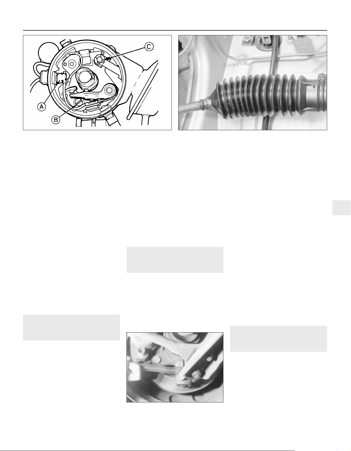
3 Pull off the contact breaker LT lead from the
points (see illustration).
4 Unscrew and remove the screw from the
fixed contact arm. Take great care not to drop
the screw into the interior of the distributor: if
necessary, cover the openings in the
baseplate with rag before starting to remove
the screw.
5 With the screw removed, lift out the contact
breaker assembly.
6 Fit and adjust the new contact breaker set,
leaving the securing screw loose until the gap
has been set.
7 Apply a little high melting-point grease to
the distributor cam. (Grease may be supplied
with the new contact breaker set.)
8 Refit the rotor arm and the distributor cap
and reconnect the spark plug leads in their
previously noted location.
9 Check and adjust the dwell angle and the
ignition timing.
24 Steering and suspension
security check
1
1 Check the shock absorbers by bouncing
the vehicle up and down at each corner in
turn. When released, it should come to rest
within one complete oscillation. Continued
movement, or squeaking and groaning noises
from the shock absorber suggests that
renewal is required.
2 With the weight of the vehicle on its
roadwheels, inspect all of the suspension
flexible bushes for wear and check the torque
wrench settings of all bolts and nuts.
3 Raise and support the vehicle. Examine all
steering and suspension components for
wear, damage and fluid leakage. Pay
particular attention to dust covers and gaiters
(see illustration), which if renewed promptly
when damaged can save further damage to
the component protected.
4 At the same intervals, check the front
suspension lower arm balljoints for wear by
levering up the arms (see illustration).
Balljoint free movement must not exceed 0.5
mm. The track rod end balljoints can be
checked in a similar manner, or by observing
them whilst an assistant rocks the steering
wheel back and forth. If the lower arm balljoint
is worn, the complete lower arm must be
renewed.
5 Wheel bearings can be checked for wear by
spinning the relevant roadwheel. Any
roughness or excessive noise indicates worn
bearings, which must be renewed, as no
adjustment is possible. It is unlikely that any
wear will be evident unless the vehicle has
covered a very high mileage. It should be
noted that it is normal for the bearings to
exhibit slight endfloat, which is perceptible as
wheel rock at the wheel rim.
25 Underbody inspection
1
1 Except on vehicles with a wax-based
underbody protective coating, have the whole
of the underframe of the vehicle steamcleaned, engine compartment included, so
that a thorough inspection can be carried out
to see what minor repairs and renovations are
necessary.
2 Steam-cleaning is available at many
garages and is necessary for the removal of
the accumulation of oily grime which
sometimes is allowed to become thick in
Every 12 000 miles or 12 months 1•15
24.4 Apply leverage to check for excessive
balljoint wear
24.3 Inspect the steering rack bellows23.3 Contact breaker points removal
A LT lead connector
B Securing screw
C Vacuum advance strut
circlip
1
Page 16
certain areas. If steam-cleaning facilities are
not available, there are some excellent grease
solvents available, which can be brushapplied; the dirt can then be simply hosed off.
3 After cleaning, position the vehicle over a pit,
or raise it at front and rear on ramps or axle
stands (see “Jacking and vehicle support”).
4 Using a strong light, work around the
underside of the vehicle, inspecting it for
corrosion or damage. If either is found, refer
to Chapter 11 for details of repair.
26 Brake pipe and hose check
1
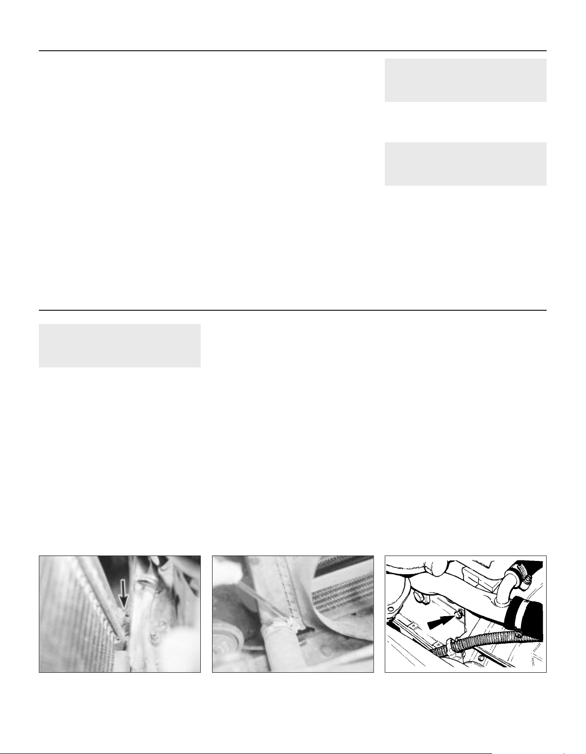
1 Periodically inspect the rigid brake pipes for
rust and other damage, and the flexible hoses
for cracks, splits or “ballooning” (see
illustration). Have an assistant depress the
brake pedal (ignition on) and inspect the hose
and pipe unions for leaks. Renew any
defective item without delay.
27 Road test
1
Instruments and electrical
equipment
1 Check the operation of all instruments and
electrical equipment.
2 Make sure that all instruments read
correctly, switch on all electrical equipment in
turn to check that it functions properly.
Steering and suspension
3 Check for any abnormalities in the steering,
suspension, handling or road “feel”.
4 Drive the vehicle, and check that there are
no unusual vibrations or noises.
5 Check that the steering feels positive, with
no excessive “sloppiness”, or roughness, and
check for any suspension noises when
cornering, or when driving over bumps.
Drivetrain
6 Check the performance of the engine,
clutch, transmission and driveshafts.
7 Listen for any unusual noises from the
engine, clutch and transmission.
8 Make sure that the engine runs smoothly
when idling, and that there is no hesitation
when accelerating.
9 Where applicable, check that the clutch
action is smooth and progressive, that the
drive is taken up smoothly, and that the pedal
travel is not excessive. Also listen for any
noises when the clutch pedal is depressed.
10 Check that all gears can be engaged
smoothly, without noise, and that the gear
lever action is not abnormally vague or
“notchy”.
Check the operation and
performance of the braking
system
11 Make sure that the vehicle does not pull to
one side when braking, and that the wheels
do not lock prematurely when braking hard.
12 Check that there is no vibration through
the steering when braking.
13 Check that the handbrake operates
correctly, without excessive movement of the
lever, and that it holds the vehicle stationary
on a slope.
14 Test the operation of the brake servo unit
as follows. With the engine off, depress the
footbrake four or five times to exhaust the
vacuum. Start the engine, holding the brake
pedal depressed. As the engine starts, there
should be a noticeable “give” in the brake
pedal as vacuum builds up. Allow the engine
to run for at least two minutes, and then
switch it off. If the brake pedal is depressed
now, it should be possible to detect a hiss
from the servo as the pedal is depressed.
After about four or five applications, no further
hissing should be heard, and the pedal should
feel considerably firmer.
28 Crankcase ventilation
system check
1
1 Inspect the crankcase ventilation system
for blockage or damage. A blocked hose can
cause a build-up of crankcase pressure,
which in turn can cause oil leaks.
2 Inspect each hose for distortion, perishing
and correct routing.
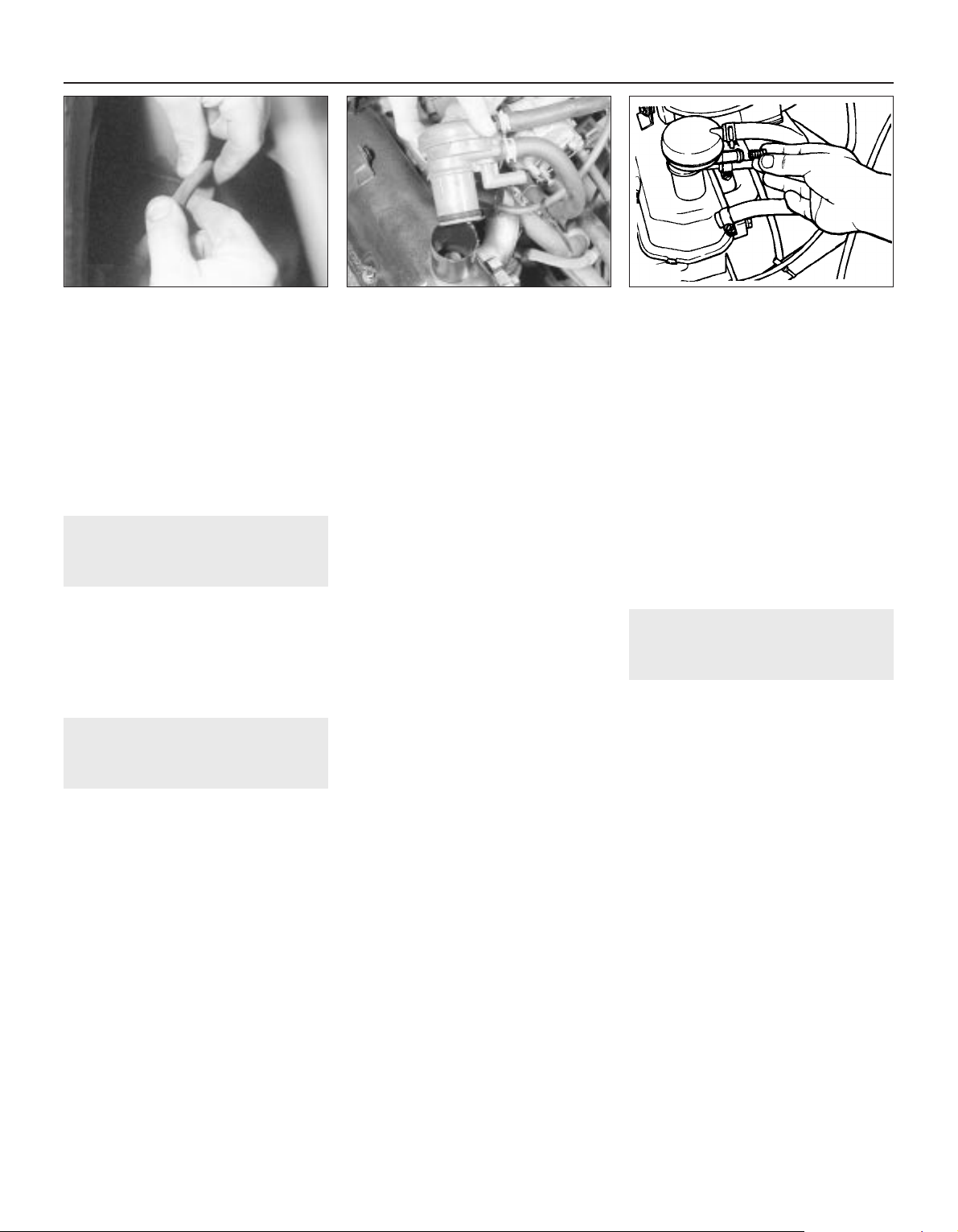
3 Clean the oil filler cap with solvent and
check that the vent hose connections are not
blocked (see illustration).
4 Clean the emission control orifice located in
the oil filler assembly with solvent (see
illustration).
1•16 Every 12 000 miles or 12 months
26.1 Bend flexible brake hoses to check
for splitting and decay
28.4 Clean emission control orifice in
solvent - OHV shown
28.3 Oil filler cap and breather hoses
Page 17
29 Air cleaner temperature
control check
2
Note: A vacuum pump will be required for this
check if the heat sensor or diaphragm unit is
at fault.
1 The air cleaner temperature control unit can
be checked for operation whilst the engine is
cold. Look into the air inlet spout and check
that the air control flap valve is in the shut
position (see illustration).
2 Now start the engine and allow it to idle.
The flap valve should open fully to allow the
warm air to be drawn into the cleaner unit
from the exhaust manifold ducting. As the
engine warms up to its normal operating
temperature the flap valve should
progressively close to allow cooler air to enter
the cleaner unit.
3 If the valve is stuck in the shut position,
check the vacuum lines for condition and
security. If these are in order, then the heat
sensor or diaphragm unit is at fault. Proceed
as follows:
4 Detach the diaphragm-to-heat sensor
vacuum pipe (at the sensor end) and connect
up a vacuum pump to the diaphragm. Pump
and apply a vacuum up to 100 mm of mercury
and retain this whilst checking the air flap.
5 If the flap opens, the heat sensor is
defective and must be renewed, but if it
remains shut then the diaphragm or control
flap is faulty.
6 Disconnect the vacuum pump and
reconnect the vacuum pipe to the sensor unit.
30 Emission control filter
element renewal - CVH
engines
1
1 Gain access to the emission control filter by
detaching the hose from the air cleaner unit
(see illustration).
2 Withdraw the used filter and fit a new item.
Ensure that the hose is securely reconnected.
31 Air cleaner element renewal
1
1 Renew the air cleaner element by first
removing the air cleaner unit lid. To do this,
undo and remove the retaining screws and
prise free the lid from the retaining clips
around its periphery (see illustration).
2 Remove and discard the paper element and
wipe out the air cleaner casing (see
illustration).
3 Place the new element in position and refit
the lid.
32 Brake hydraulic system seal
and hose renewal
3
If in doubt as to the condition of any of the
brake system seals and hoses, then renew
defective items whilst referring to the relevant
Sections of Chapter 9.
33 Brake hydraulic fluid renewal
2
1 An assistant and bleeding equipment will
be needed. A considerable quantity of
hydraulic fluid will be required - probably
about 2 litres.
2 Slacken the front wheel nuts. Raise and
support the front of the vehicle and remove
the front wheels.
3 Remove the hydraulic fluid reservoir cap.
4 Open both front bleed screws one full turn.
Attach one bleed tube to each screw, placing
the free end of each tube in a jar.
5 Pump the brake pedal to expel fluid from
the bleed screws. Pause after each upstroke
to allow the master cylinder to refill.
Every 24 000 miles or 2 years 1•17
31.1 Remove the air cleaner lid securing
screws . . .
30.1 Detach hose downwards for access
to crankcase emission filter in air cleaner
body
29.1 Air cleaner inlet sensor and
diaphragm flap valve operating modes
1 Sensor cold 2 Sensor hot
1
24 000 Mile (40 000 Km) / every 2 years
36 000 Mile (60 000 Km) / every 3 years
31.2 . . . to expose the air cleaner element
Page 18
6 When air emerges from both bleed screws,
stop pumping. Detach the left-hand caliper
without disconnecting it and remove the
inboard brake pad.
7 Depress the caliper piston, using a
purpose-made tool or a blunt item such as a
tyre lever, to force more fluid out of the
caliper. Hold the piston depressed and have
the assistant pump the pedal until air emerges
from the bleed screw again.
8 Tighten the bleed screw on the left-hand
caliper. Loosely refit the caliper and pad so
that the piston is not accidentally ejected.
9 Repeat the purging operation on the righthand caliper, but do not refit it or tighten the
bleed screw yet.
10 Fill the reservoir with fresh hydraulic fluid.
Position the bleed jar for the right-hand
caliper at least 300 mm above the level of the
bleed screw.
11 Have the assistant pump the brake pedal
until fluid free of bubbles emerges from the
bleed screw. Tighten the bleed screw at the
end of a downstroke.
12 Place a piece of wood in the caliper jaws
to limit piston travel. Keep your fingers clear
of the piston. Have the assistant depress the
brake pedal gently in order to move the
caliper piston out.
13 With the pedal held depressed, slacken
the bleed screw on the right-hand caliper and
again depress the piston. Tighten the bleed
screw when the piston is retracted. The pedal
can now be released.
14 Disconnect the bleed tube. Refit the righthand brake pad and caliper.
15 Remove the left-hand caliper and inboard
pad again. Carry out the operations described
in paragraphs 10 to 14 on the left-hand
caliper.
16 Bleed the rear brakes as described in
Chapter 9.
17 Refit the front wheels, lower the vehicle
and tighten the wheel nuts.
18 Pump the brake pedal to bring the pads
up to the discs, then make a final check of the
hydraulic fluid level. Top-up and refit the
reservoir cap.
34 Timing belt renewal - CVH
engines
3
Timing belt renewal is recommended for
CVH engines. Refer to Chapter 2, Part B for
the appropriate renewal procedure.
35 Front wheel alignment check
3
Due to the need for precision equipment to
accurately measure the small angles of the
steering and suspension settings appertaining
to front wheel alignment, it is preferable to
leave this work to a specialist. However, if you
wish to check front wheel alignment yourself,
refer to the information given in Chapter 10.
36 Engine coolant renewal
1
Draining
1 It is preferable to drain the system when the
coolant is cold. If it must be drained when hot,
release the pressure cap very slowly having
first covered it with a cloth to avoid any
possibility of scalding.
2 Set the heater control to maximum heat
position.
3 Place a container under the radiator and
release the bottom hose or, where fitted,
unscrew the radiator drain plug and allow the
system to drain into the container (see
illustrations).
Flushing
4 Provided the coolant is of the specified
type, then no flushing should be necessary.
5 Where the system has been neglected
however, and rust or sludge is evident at
draining, then the system should be flushed
through with a cold water hose inserted into
the thermostat housing (thermostat removed)
until the water flows clean from the
disconnected bottom hose and the radiator.
If, after a reasonable period, the water still
does not run clear the radiator can be flushed
with a good proprietary cleaning agent.
6 In severe cases, the drain plug on the
cylinder block of OHV models can be
unscrewed to assist sludge removal and
flushing (see illustration). On CVH models
there is no drain plug on the cylinder block so
you will need to detach the bottom hose.
7 If the radiator is suspected of being
clogged, remove it and reverse flush it with a
cold water hose. The normal coolant flow is
from left to right (from the thermostat housing
to the radiator) through the matrix and out of
the opposite side.
8 When the coolant is being changed, it is
recommended that the overflow pipe is
disconnected from the expansion tank and
the coolant drained from the tank. If the
interior of the tank is dirty, remove it and
thoroughly clean it out. Evidence of oil within
the expansion tank may indicate a leaking
cylinder head gasket.
Refilling
9 Reconnect the radiator and expansion tank
hoses, and refit the cylinder block drain plug
(OHV), or connect the bottom hose (CVH), as
applicable.
10 Using the specified antifreeze (see
“Lubricants and fluids”), fill the system via the
expansion tank, until the coolant level reaches
the “maximum” mark. Allow time for air in the
system to bubble through and add more
coolant if necessary. Repeat until the level
does not drop and refit the cap.
11 Start the engine and run it to normal
operating temperature. Once it has cooled,
check and carry out any final topping-up to
the expansion tank.
1•18 Every 36 000 miles or 3 years
36.6 The cylinder block drain plug
(arrowed) - OHV
36.3b The radiator bottom hose clamp36.3a The radiator drain plug (arrowed)
Every 2 years (regardless of mileage)
Page 19

2A
General
Engine type . . . . . . . . . . . . . . . . . . . . . . . . . . . . . . . . . . . . . . . . . . . . . . . Four-cylinder, overhead valve, water-cooled
1.0 litre 1.1 litre
Firing order (No 1 at timing cover end) . . . . . . . . . . . . . . . . . . . . . . . . . . 1-2-4-3 1-2-4-3
Bore . . . . . . . . . . . . . . . . . . . . . . . . . . . . . . . . . . . . . . . . . . . . . . . . . . . . 73.96 mm 73.96 mm
Stroke . . . . . . . . . . . . . . . . . . . . . . . . . . . . . . . . . . . . . . . . . . . . . . . . . . . 55.70 mm 64.98 mm
Cubic capacity . . . . . . . . . . . . . . . . . . . . . . . . . . . . . . . . . . . . . . . . . . . . 957 cc 1117 cc
Compression ratio . . . . . . . . . . . . . . . . . . . . . . . . . . . . . . . . . . . . . . . . . 8.5 : 1 9.5 : 1
Compression pressure at starter speed . . . . . . . . . . . . . . . . . . . . . . . . . 9.5 to 11.5 kgf/cm
2
13.3 to 15.3 kgf/cm
2
Idle speed (rpm) . . . . . . . . . . . . . . . . . . . . . . . . . . . . . . . . . . . . . . . . . . . 750 to 850 750 to 850
Maximum continuous engine speed (rpm) . . . . . . . . . . . . . . . . . . . . . . . 5950 5450
Engine output (DIN) . . . . . . . . . . . . . . . . . . . . . . . . . . . . . . . . . . . . . . . . 33 kW at 5750 rpm 37 kW at 5000 rpm
Engine torque (DIN) . . . . . . . . . . . . . . . . . . . . . . . . . . . . . . . . . . . . . . . . 6.9 kgf m at 3700 rpm 8.4 kgf m at 2700 rpm
Cylinder block
Number of main bearings . . . . . . . . . . . . . . . . . . . . . . . . . . . . . . . . . . . . 3
Cylinder bore diameter:
Standard (1) . . . . . . . . . . . . . . . . . . . . . . . . . . . . . . . . . . . . . . . . . . . . 73.940 to 73.950 mm
Standard (2) . . . . . . . . . . . . . . . . . . . . . . . . . . . . . . . . . . . . . . . . . . . . 73.950 to 73.960 mm
Standard (3) . . . . . . . . . . . . . . . . . . . . . . . . . . . . . . . . . . . . . . . . . . . . 73.960 to 73.970 mm
Standard (4) and service . . . . . . . . . . . . . . . . . . . . . . . . . . . . . . . . . . . 73.970 to 73.980 mm
Oversizes:
0.5 . . . . . . . . . . . . . . . . . . . . . . . . . . . . . . . . . . . . . . . . . . . . . . . . . . . . 74.500 to 74.510 mm
1.0 . . . . . . . . . . . . . . . . . . . . . . . . . . . . . . . . . . . . . . . . . . . . . . . . . . . . 75.000 to 75.010 mm
Main bearing bore:
Standard . . . . . . . . . . . . . . . . . . . . . . . . . . . . . . . . . . . . . . . . . . . . . . . 60.623 to 60.636 mm
Oversize . . . . . . . . . . . . . . . . . . . . . . . . . . . . . . . . . . . . . . . . . . . . . . . 61.003 to 61.016 mm
Camshaft bearing bore:
Standard . . . . . . . . . . . . . . . . . . . . . . . . . . . . . . . . . . . . . . . . . . . . . . . 42.888 to 42.918 mm
Oversize . . . . . . . . . . . . . . . . . . . . . . . . . . . . . . . . . . . . . . . . . . . . . . . 43.396 to 43.420 mm
Central main bearing width (less thrustwashers) . . . . . . . . . . . . . . . . . . 22.04 to 22.10 mm
Crankshaft
Endfloat . . . . . . . . . . . . . . . . . . . . . . . . . . . . . . . . . . . . . . . . . . . . . . . . . . 0.072 to 0.285 mm
Main journal diameter:
Standard . . . . . . . . . . . . . . . . . . . . . . . . . . . . . . . . . . . . . . . . . . . . . . . 56.990 to 57.000 mm
Yellow dot . . . . . . . . . . . . . . . . . . . . . . . . . . . . . . . . . . . . . . . . . . . . . . 56.980 to 56.990 mm
0.254 undersize . . . . . . . . . . . . . . . . . . . . . . . . . . . . . . . . . . . . . . . . . . 56.726 to 56.746 mm
0.508 undersize . . . . . . . . . . . . . . . . . . . . . . . . . . . . . . . . . . . . . . . . . . 56.472 to 56.492 mm
0.762 undersize . . . . . . . . . . . . . . . . . . . . . . . . . . . . . . . . . . . . . . . . . . 56.218 to 56.238 mm
Chapter 2 Part A:
OHV engine repair procedures
Crankshaft front oil seal - renewal . . . . . . . . . . . . . . . . . . . . . . . . . . . .8
Cylinder head - removal and refitting . . . . . . . . . . . . . . . . . . . . . . . . . .4
Cylinder head and pistons - decarbonising . . . . . . . . . . . . . . . . . . . .15
Engine - dismantling . . . . . . . . . . . . . . . . . . . . . . . . . . . . . . . . . . . . . .13
Engine - examination and renovation . . . . . . . . . . . . . . . . . . . . . . . . .14
Engine - reassembly . . . . . . . . . . . . . . . . . . . . . . . . . . . . . . . . . . . . . .16
Engine/transmission mountings - removal and refitting . . . . . . . . . . .11
Engine/transmission - reconnection and refitting . . . . . . . . . . . . . . . .17
Engine/transmission - removal and separation . . . . . . . . . . . . . . . . .12
General information . . . . . . . . . . . . . . . . . . . . . . . . . . . . . . . . . . . . . . .1
Oil filter and pump - removal and refitting . . . . . . . . . . . . . . . . . . . . .10
Operations only possible with engine removed from vehicle . . . . . . . .3
Operations possible without removing engine from vehicle . . . . . . . . .2
Pistons/connecting rods - removal and refitting . . . . . . . . . . . . . . . . .9
Rocker gear - dismantling and reassembly . . . . . . . . . . . . . . . . . . . . .7
Sump - removal and refitting . . . . . . . . . . . . . . . . . . . . . . . . . . . . . . . .6
Valve clearances - adjustment . . . . . . . . . . . . . . . . . . . . . . . . . . . . . . .5
2A•1
Specifications
Contents
Easy, suitable for
novice with little
experience
Fairly easy, suitable
for beginner with
some experience
Fairly difficult,
suitable for competent
DIY mechanic
Difficult, suitable for
experienced DIY
mechanic
Very difficult,
suitable for expert DIY
or professional
Degrees of difficulty
5
4
3
2
1
Page 20

Crankshaft (continued)
Main bearing shell width . . . . . . . . . . . . . . . . . . . . . . . . . . . . . . . . . . . . . 21.2 to 21.6 mm
Main bearing shell play . . . . . . . . . . . . . . . . . . . . . . . . . . . . . . . . . . . . . . 0.009 to 0.046 mm
Crankpin (big-end) diameter:
Standard . . . . . . . . . . . . . . . . . . . . . . . . . . . . . . . . . . . . . . . . . . . . . . . 42.99 to 43.01 mm
0.254 undersize . . . . . . . . . . . . . . . . . . . . . . . . . . . . . . . . . . . . . . . . . . 42.74 to 42.76 mm
0.508 undersize . . . . . . . . . . . . . . . . . . . . . . . . . . . . . . . . . . . . . . . . . . 42.49 to 42.51 mm
0.762 undersize . . . . . . . . . . . . . . . . . . . . . . . . . . . . . . . . . . . . . . . . . . 42.24 to 42.26 mm
Thrustwasher thicknesses:
Standard . . . . . . . . . . . . . . . . . . . . . . . . . . . . . . . . . . . . . . . . . . . . . . . 2.80 to 2.85 mm
Oversize . . . . . . . . . . . . . . . . . . . . . . . . . . . . . . . . . . . . . . . . . . . . . . . 2.99 to 3.04 mm
Camshaft
Number of bearings . . . . . . . . . . . . . . . . . . . . . . . . . . . . . . . . . . . . . . . . 3
Camshaft bearing diameter . . . . . . . . . . . . . . . . . . . . . . . . . . . . . . . . . . 39.615 to 39.635 mm
Bearing bush inside diameter . . . . . . . . . . . . . . . . . . . . . . . . . . . . . . . . . 39.662 to 39.682 mm
Camshaft thrust plate thickness . . . . . . . . . . . . . . . . . . . . . . . . . . . . . . . 4.457 to 4.508 mm
Camshaft endfloat . . . . . . . . . . . . . . . . . . . . . . . . . . . . . . . . . . . . . . . . . 0.062 to 0.193 mm
Cam lift:
Inlet valve . . . . . . . . . . . . . . . . . . . . . . . . . . . . . . . . . . . . . . . . . . . . . . 5.300 mm
Exhaust valve . . . . . . . . . . . . . . . . . . . . . . . . . . . . . . . . . . . . . . . . . . . 5.300 mm
Cam length (heel to toe):
Inlet . . . . . . . . . . . . . . . . . . . . . . . . . . . . . . . . . . . . . . . . . . . . . . . . . . . 32.288 to 32.516 mm
Exhaust . . . . . . . . . . . . . . . . . . . . . . . . . . . . . . . . . . . . . . . . . . . . . . . . 32.615 to 32.846 mm
Pistons
Diameter:
Standard (1) . . . . . . . . . . . . . . . . . . . . . . . . . . . . . . . . . . . . . . . . . . . . 73.910 to 73.920 mm
Standard (2) . . . . . . . . . . . . . . . . . . . . . . . . . . . . . . . . . . . . . . . . . . . . 73.920 to 73.930 mm
Standard (3) . . . . . . . . . . . . . . . . . . . . . . . . . . . . . . . . . . . . . . . . . . . . 73.930 to 73.940 mm
Standard (4) . . . . . . . . . . . . . . . . . . . . . . . . . . . . . . . . . . . . . . . . . . . . 73.940 to 73.950 mm
Standard service . . . . . . . . . . . . . . . . . . . . . . . . . . . . . . . . . . . . . . . . . 73.930 to 73.955 mm
0.5 oversize . . . . . . . . . . . . . . . . . . . . . . . . . . . . . . . . . . . . . . . . . . . . . 74.460 to 74.485 mm
1.0 oversize . . . . . . . . . . . . . . . . . . . . . . . . . . . . . . . . . . . . . . . . . . . . . 74.960 to 74.985 mm
Piston-to-bore clearance . . . . . . . . . . . . . . . . . . . . . . . . . . . . . . . . . . . . 0.015 to 0.050 mm
Piston ring gap (fitted):
Top and 2nd rings . . . . . . . . . . . . . . . . . . . . . . . . . . . . . . . . . . . . . . . . 0.25 to 0.45 mm
Bottom ring . . . . . . . . . . . . . . . . . . . . . . . . . . . . . . . . . . . . . . . . . . . . . 0.20 to 0.40 mm
Bottom (oil control) ring gap position . . . . . . . . . . . . . . . . . . . . . . . . . . . In line with gudgeon pin
2nd ring gap position . . . . . . . . . . . . . . . . . . . . . . . . . . . . . . . . . . . . . . . 90° to oil control ring gap
Top ring gap position . . . . . . . . . . . . . . . . . . . . . . . . . . . . . . . . . . . . . . . 180° to oil control ring gap
Gudgeon pins
Pin length . . . . . . . . . . . . . . . . . . . . . . . . . . . . . . . . . . . . . . . . . . . . . . . . 54.6 to 55.4 mm
Pin diameters:
White . . . . . . . . . . . . . . . . . . . . . . . . . . . . . . . . . . . . . . . . . . . . . . . . . . 20.622 to 20.625 mm
Red . . . . . . . . . . . . . . . . . . . . . . . . . . . . . . . . . . . . . . . . . . . . . . . . . . . 20.625 to 20.628 mm
Blue . . . . . . . . . . . . . . . . . . . . . . . . . . . . . . . . . . . . . . . . . . . . . . . . . . . 20.628 to 20.631 mm
Yellow . . . . . . . . . . . . . . . . . . . . . . . . . . . . . . . . . . . . . . . . . . . . . . . . . 20.631 to 20.634 mm
Connecting rod interference at 21°C (70°F) . . . . . . . . . . . . . . . . . . . . . . 0.013 to 0.045 mm
Pin-to-piston interference at 21°C (70°F) . . . . . . . . . . . . . . . . . . . . . . . . 0.005 to 0.011 mm
Connecting rods
Big-end bore diameter . . . . . . . . . . . . . . . . . . . . . . . . . . . . . . . . . . . . . . 46.685 to 46.705 mm
Small-end bore diameter . . . . . . . . . . . . . . . . . . . . . . . . . . . . . . . . . . . . 20.589 to 20.609 mm
Bearing shell inside diameter (fitted):
Standard . . . . . . . . . . . . . . . . . . . . . . . . . . . . . . . . . . . . . . . . . . . . . . . 43.016 to 43.050 mm
0.254 undersize . . . . . . . . . . . . . . . . . . . . . . . . . . . . . . . . . . . . . . . . . . 42.768 to 42.802 mm
0.508 undersize . . . . . . . . . . . . . . . . . . . . . . . . . . . . . . . . . . . . . . . . . . 42.518 to 42.552 mm
0.762 undersize . . . . . . . . . . . . . . . . . . . . . . . . . . . . . . . . . . . . . . . . . . 42.268 to 42.302 mm
1.016 undersize . . . . . . . . . . . . . . . . . . . . . . . . . . . . . . . . . . . . . . . . . . 42.018 to 42.052 mm
Journal-to-bearing shell clearance . . . . . . . . . . . . . . . . . . . . . . . . . . . . . 0.006 to 0.060 mm
Cylinder head
Valve seat angle (inlet and exhaust) . . . . . . . . . . . . . . . . . . . . . . . . . . . . 45°
Valve seat width (inlet and exhaust) . . . . . . . . . . . . . . . . . . . . . . . . . . . . 1.20 to 1.75 mm
Lower correction angle (inlet and exhaust) . . . . . . . . . . . . . . . . . . . . . . . 30°
Upper correction angle (inlet and exhaust) . . . . . . . . . . . . . . . . . . . . . . . 80°
Upper correction angle - service cutter . . . . . . . . . . . . . . . . . . . . . . . . . 75°
Valve stem bore (inlet and exhaust):
Standard . . . . . . . . . . . . . . . . . . . . . . . . . . . . . . . . . . . . . . . . . . . . . . . 7.907 to 7.938 mm
0.381 oversize . . . . . . . . . . . . . . . . . . . . . . . . . . . . . . . . . . . . . . . . . . . 8.288 to 8.319 mm
2A•2 OHV engine repair procedures
Page 21

Valves
Clearances . . . . . . . . . . . . . . . . . . . . . . . . . . . . . . . . . . . . . . . . . . . . . . . See Servicing Specifications in Chapter 1
Tappet diameter . . . . . . . . . . . . . . . . . . . . . . . . . . . . . . . . . . . . . . . . . . . 13.081 to 13.094 mm
Tappet clearance in cylinder block . . . . . . . . . . . . . . . . . . . . . . . . . . . . . 20.25 to 20.75 mm
Valve spring free length (inlet and exhaust) . . . . . . . . . . . . . . . . . . . . . . 42 mm
Valve lift (excluding clearance) (inlet and exhaust) . . . . . . . . . . . . . . . . . 8.367 mm
Valve head diameter:
Inlet . . . . . . . . . . . . . . . . . . . . . . . . . . . . . . . . . . . . . . . . . . . . . . . . . . . 32.89 to 33.15 mm
Exhaust . . . . . . . . . . . . . . . . . . . . . . . . . . . . . . . . . . . . . . . . . . . . . . . . 29.01 to 29.27 mm
Valve stem diameter:
Inlet valves:
Standard . . . . . . . . . . . . . . . . . . . . . . . . . . . . . . . . . . . . . . . . . . . . . 7.868 to 7.886 mm
0.076 oversize . . . . . . . . . . . . . . . . . . . . . . . . . . . . . . . . . . . . . . . . . 7.944 to 7.962 mm
0.381 oversize . . . . . . . . . . . . . . . . . . . . . . . . . . . . . . . . . . . . . . . . . 8.249 to 8.267 mm
Exhaust valves:
Standard . . . . . . . . . . . . . . . . . . . . . . . . . . . . . . . . . . . . . . . . . . . . . 7.846 to 7.864 mm
0.076 oversize . . . . . . . . . . . . . . . . . . . . . . . . . . . . . . . . . . . . . . . . . 7.922 to 7.940 mm
0.381 oversize . . . . . . . . . . . . . . . . . . . . . . . . . . . . . . . . . . . . . . . . . 8.227 to 8.245 mm
Valve stem-to-guide clearance:
Inlet . . . . . . . . . . . . . . . . . . . . . . . . . . . . . . . . . . . . . . . . . . . . . . . . . . . 0.021 to 0.070 mm
Exhaust . . . . . . . . . . . . . . . . . . . . . . . . . . . . . . . . . . . . . . . . . . . . . . . . 0.043 to 0.092 mm
Valve timing:
Inlet valve opens . . . . . . . . . . . . . . . . . . . . . . . . . . . . . . . . . . . . . . . . . 14° BTDC
Inlet valve closes . . . . . . . . . . . . . . . . . . . . . . . . . . . . . . . . . . . . . . . . . 46° ABDC
Exhaust valve opens . . . . . . . . . . . . . . . . . . . . . . . . . . . . . . . . . . . . . . 65° BBDC
Exhaust valve closes . . . . . . . . . . . . . . . . . . . . . . . . . . . . . . . . . . . . . . 11° ATDC
Lubrication system
Minimum oil pressure at 80°C (175°F) . . . . . . . . . . . . . . . . . . . . . . . . . . 0.6 kgf/cm2at 750 rpm
Warning light operates at . . . . . . . . . . . . . . . . . . . . . . . . . . . . . . . . . . . . 0.32 to 0.53 kgf/cm
2
Relief valve opening pressure . . . . . . . . . . . . . . . . . . . . . . . . . . . . . . . . . 2.41 to 2.75 kgf/cm
2
Oil pump clearances:
Outer rotor-to-housing . . . . . . . . . . . . . . . . . . . . . . . . . . . . . . . . . . . . 0.14 to 0.26 mm
Inner-to-outer rotor . . . . . . . . . . . . . . . . . . . . . . . . . . . . . . . . . . . . . . . 0.051 to 0.127 mm
Rotors-to-cover endfloat . . . . . . . . . . . . . . . . . . . . . . . . . . . . . . . . . . 0.025 to 0.06 mm
Torque wrench settings Nm lbf ft
Main bearing cap bolts . . . . . . . . . . . . . . . . . . . . . . . . . . . . . . . . . . . . . . 95 70
Connecting rod (big-end) bolts . . . . . . . . . . . . . . . . . . . . . . . . . . . . . . . . 31 23
Rear oil seal retainer bolts . . . . . . . . . . . . . . . . . . . . . . . . . . . . . . . . . . . 18 13
Flywheel bolts . . . . . . . . . . . . . . . . . . . . . . . . . . . . . . . . . . . . . . . . . . . . . 68 50
Chain tensioner bolts . . . . . . . . . . . . . . . . . . . . . . . . . . . . . . . . . . . . . . . 8 6
Camshaft thrust plate bolts . . . . . . . . . . . . . . . . . . . . . . . . . . . . . . . . . . 4 3
Camshaft sprocket bolts . . . . . . . . . . . . . . . . . . . . . . . . . . . . . . . . . . . . 19 14
Timing cover bolts . . . . . . . . . . . . . . . . . . . . . . . . . . . . . . . . . . . . . . . . . 10 7
Coolant pump bolts . . . . . . . . . . . . . . . . . . . . . . . . . . . . . . . . . . . . . . . . 10 7
Crankshaft pulley bolt . . . . . . . . . . . . . . . . . . . . . . . . . . . . . . . . . . . . . . . 54 40
Coolant pump pulley bolts . . . . . . . . . . . . . . . . . . . . . . . . . . . . . . . . . . . 10 7
Starter motor bolts . . . . . . . . . . . . . . . . . . . . . . . . . . . . . . . . . . . . . . . . . 41 30
Fuel pump bolts . . . . . . . . . . . . . . . . . . . . . . . . . . . . . . . . . . . . . . . . . . . 18 13
Oil pump bolts . . . . . . . . . . . . . . . . . . . . . . . . . . . . . . . . . . . . . . . . . . . . 19 14
Sump drain plug . . . . . . . . . . . . . . . . . . . . . . . . . . . . . . . . . . . . . . . . . . . 25 18
Sump fixing bolts:
Stage 1 . . . . . . . . . . . . . . . . . . . . . . . . . . . . . . . . . . . . . . . . . . . . . . . . 8 6
Stage 2 . . . . . . . . . . . . . . . . . . . . . . . . . . . . . . . . . . . . . . . . . . . . . . . . 11 8
Stage 3 . . . . . . . . . . . . . . . . . . . . . . . . . . . . . . . . . . . . . . . . . . . . . . . . 11 8
Oil pressure sender . . . . . . . . . . . . . . . . . . . . . . . . . . . . . . . . . . . . . . . . . 15 11
Coolant temperature sender . . . . . . . . . . . . . . . . . . . . . . . . . . . . . . . . . . 15 11
Rocker shaft pedestal bolts . . . . . . . . . . . . . . . . . . . . . . . . . . . . . . . . . . 42 31
Cylinder head bolts:
Stage 1 . . . . . . . . . . . . . . . . . . . . . . . . . . . . . . . . . . . . . . . . . . . . . . . . 15 11
Stage 2 . . . . . . . . . . . . . . . . . . . . . . . . . . . . . . . . . . . . . . . . . . . . . . . . 48 35
Stage 3 . . . . . . . . . . . . . . . . . . . . . . . . . . . . . . . . . . . . . . . . . . . . . . . . 88 65
Stage 4 (after 15 minutes delay) . . . . . . . . . . . . . . . . . . . . . . . . . . . . . 109 80
Rocker cover screws . . . . . . . . . . . . . . . . . . . . . . . . . . . . . . . . . . . . . . . 4 3
Exhaust manifold nuts and bolts . . . . . . . . . . . . . . . . . . . . . . . . . . . . . . 16 12
Inlet manifold nuts and bolts . . . . . . . . . . . . . . . . . . . . . . . . . . . . . . . . . 19 14
Carburettor flange nuts . . . . . . . . . . . . . . . . . . . . . . . . . . . . . . . . . . . . . . 19 14
Thermostat housing cover bolts . . . . . . . . . . . . . . . . . . . . . . . . . . . . . . . 19 14
Spark plugs . . . . . . . . . . . . . . . . . . . . . . . . . . . . . . . . . . . . . . . . . . . . . . . 19 14
Engine-to-transmission bolts . . . . . . . . . . . . . . . . . . . . . . . . . . . . . . . . . 41 30
Transmission oil filler plug . . . . . . . . . . . . . . . . . . . . . . . . . . . . . . . . . . . 25 18
OHV engine repair procedures 2A•3
2A
Page 22
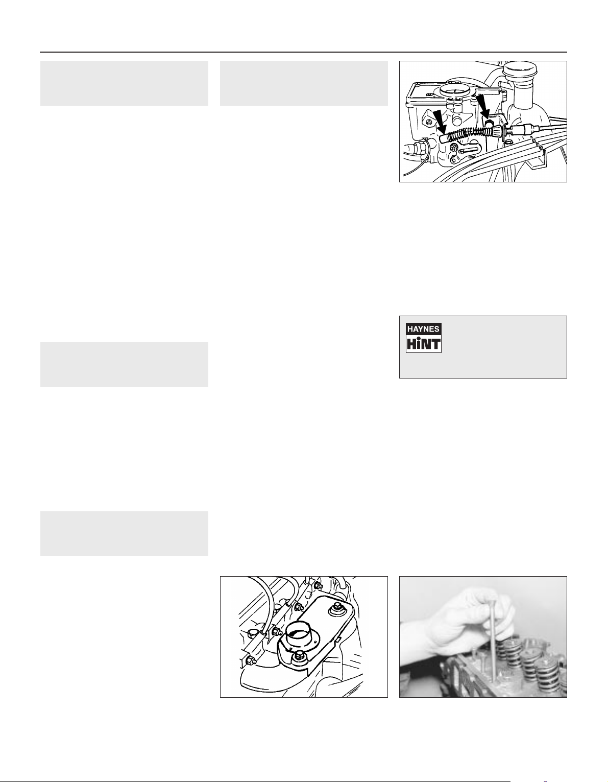
1 General information
The engine is of an overhead valve type
based upon the “Kent” design used in many
earlier Ford models. It is mounted transversely
at the front of the vehicle together with the
transmission to form a combined power train.
The engine is a water-cooled, four-cylinder
in-line type, having overhead valves operated
by tappets, pushrods and rocker arms. The
camshaft is located within the cylinder block
and chain-driven from the crankshaft. A gear
on the camshaft drives the oil pump and the
distributor, whilst a cam operates the fuel
pump lever.
The cylinder head is of crossflow type,
having the exhaust manifold mounted on the
opposite side to the inlet manifold. The
crankshaft runs in three main bearings, with
endfloat controlled by semi-circular
thrustwashers located on either side of the
centre main bearing.
The oil pump is mounted externally on the
cylinder block just below the distributor, and
the full-flow type oil filter is screwed directly
into the oil pump.
2 Operations possible without
removing engine from
vehicle
1 The following work can be carried out
without having to remove the engine:
a) Cylinder head - removal and refitting
b) Valve clearances - adjustment
c) Sump - removal and refitting
d) Rocker gear - overhaul
e) Crankshaft front oil seal - renewal
f) Pistons/connecting rods - removal and
refitting
g) Engine mountings - renewal
h) Oil filter - removal and refitting
i) Oil pump - removal and refitting
3 Operations only possible
with engine removed from
vehicle
1 The following work should be carried out
only after the engine has been removed from
the vehicle.
a) *Crankshaft main bearings - renewal
b) Crankshaft - removal and refitting
c) **Flywheel - removal and refitting
d) **Crankshaft rear oil seal - renewal
e) Camshaft - removal and refitting
f) Timing gears and chain - removal and
refitting
2 Although it is possible to undertake the job
marked * without removing the engine, and
those marked ** by removing the
transmission, such work is not recommended
and is unlikely to save much time over that
required to withdraw the complete engine/
transmission.
4 Cylinder head - removal and
refitting
3
Removal
1 If the engine is in the vehicle, carry out the
preliminary operations described in
paragraphs 2 to 15.
2 Open the bonnet and fit protective covers
to the front wing upper surfaces.
3 Disconnect the battery earth strap. It is as
well to remove the battery, so that no metal
objects are placed across its terminals.
4 Remove the air cleaner unit.
5 Drain the cooling system. Note that the
coolant should have an antifreeze solution mix
and can be used again, so drain into a
suitable container for re-use.
6 Disconnect the hoses from the thermostat
housing.
7 Detach the choke cable.
8 Release the throttle cable from the
carburettor operating lever by moving the
spring clip and removing the bracket fixing
bolt (see illustration).
9 Disconnect the fuel and vacuum pipes from
the carburettor.
10 Disconnect the breather hose from the
inlet manifold.
11 On vehicles with servo-assisted brakes,
disconnect the vacuum hose from the inlet
manifold.
12 Disconnect the HT leads from the spark
plugs.
13 Disconnect the electrical leads from the
temperature sender unit, inlet manifold,
carburettor and radiator fan thermal switch.
14 Unbolt and remove the heated air box
from the exhaust manifold (where fitted) (see
illustration).
15 Disconnect the exhaust downpipe from
the manifold by unbolting the connecting
flanges. Support the exhaust system at the
front end.
16 Pull free and remove the oil filler cap with
breather hoses.
17 Extract the four screws and remove the
rocker cover.
18 Unscrew and remove the four fixing bolts
and lift away the rocker shaft assembly from
the cylinder head.
19 Withdraw the pushrods, keeping them in
their originally fitted sequence. A simple way
to do this is to punch holes in a piece of card
and number them 1 to 8 from the thermostat
housing end of the cylinder head (see
illustration).
20 Remove the spark plugs.
21 Unscrew the cylinder head bolts
progressively in the reverse order to that given
for tightening. Remove the cylinder head.
Refitting
Caution: Never use jointing compound
when refitting the cylinder head and
gasket.
22 Before refitting the cylinder head, remove
every particle of carbon, old gasket and dirt
from the mating surfaces of the cylinder head
and block. Do not let the removed material
drop into the cylinder bores or waterways: if it
does, remove it. Normally, when a cylinder
head is removed, the head is decarbonised
and the valves ground in to remove all traces
of carbon.
23 Clean the threads of the cylinder head
bolts and mop out oil from the bolt holes in
the cylinder block. In extreme cases, screwing
a bolt into an oil-filled hole can cause the
block to fracture due to hydraulic pressure.
2A•4 OHV engine repair procedures
4.14 Heated air box on exhaust manifold
4.8 Disconnect the throttle cable and
bracket
4.19 Withdraw the pushrods
Tap a stuck cylinder head
free with a wooden mallet.
Do not insert a lever into the
head joint as this may
damage the mating faces.
Page 23
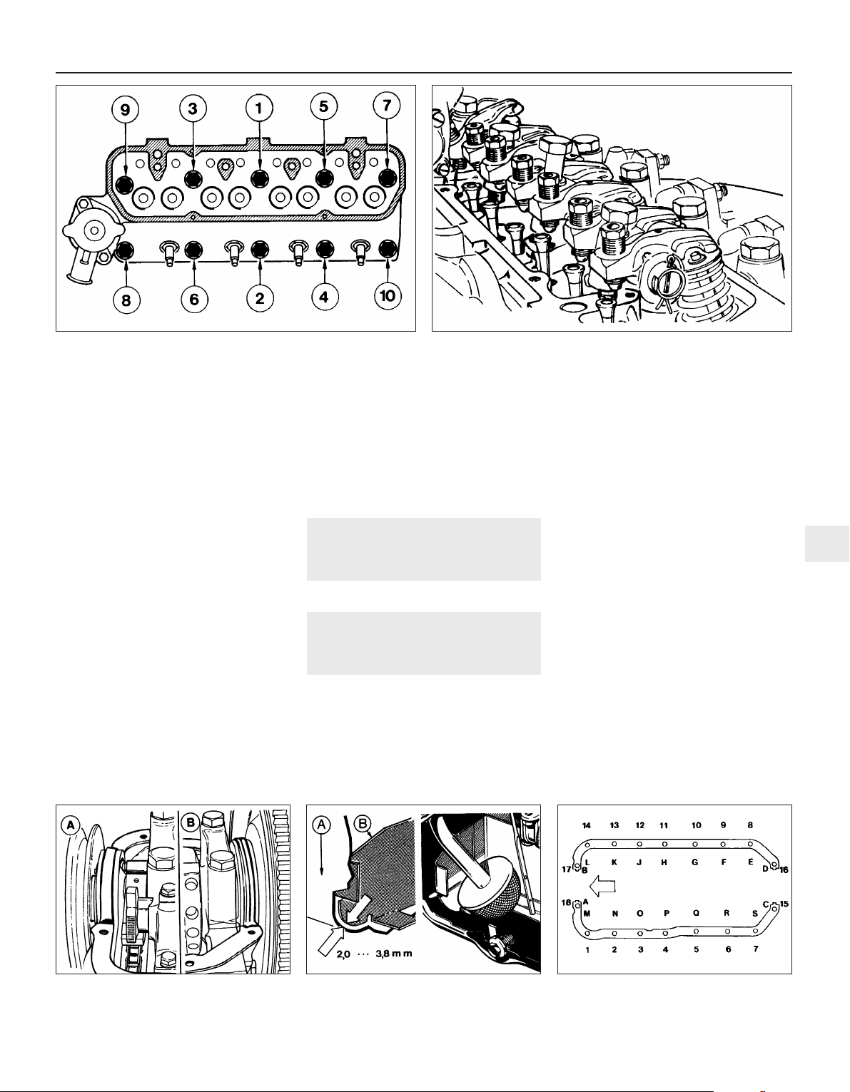
24 If there is any doubt about the condition of
the inlet or exhaust gaskets, unbolt the
manifolds and fit new ones to perfectly clean
mating surfaces.
25 Locate a new cylinder head gasket on the
cylinder block, making quite sure that the bolt
holes, coolant passages and lubrication holes
are correctly aligned.
26 Lower the cylinder head carefully into
position on the block.
27 Screw in all the bolts finger tight and then
tighten them in four stages, in the sequence
shown (see illustration) to the specified torque.
28 Refit the pushrods in their original order.
29 Lower the rocker shaft assembly into
position, making sure that the rocker
adjusting screws engage in the sockets at the
ends of the pushrods (see illustration).
30 Screw in the rocker pedestal bolts finger
tight. At this stage, some of the rocker arms
will be applying pressure to the ends of the
valve stems and some of the rocker pedestals
will not be in contact with the cylinder head.
The pedestals will be pulled down, however,
when the bolts are tightened to the specified
torque, which should now be done.
31 Adjust the valve clearances.
32 Refit the rocker cover. If the gasket is in
anything but perfect condition, renew it.
33 Fit the oil filler cap and breather hose and
the spark plugs. Tighten these to the specified
torque. They are of tapered seat type, no
sealing washers being used.
34 Connect the exhaust downpipe and fit the
heated air box.
35 Reconnect all electrical leads, vacuum
and coolant hoses.
36 Reconnect the cables. Refit the battery (if
removed) and reconnect the battery terminals.
37 Fit the air cleaner.
38 Refill the cooling system.
5 Valve clearances -
adjustment
2
Refer to Chapter 1, Section 18.
6 Sump - removal and refitting
2
Removal
1 Disconnect the battery earth lead and drain
the engine oil.
2 Unbolt and withdraw the starter motor.
Support the motor to avoid straining the
electrical wiring.
3 Unbolt and remove the clutch cover plate.
4 Extract the sump securing bolts and
remove the sump. If it is stuck, prise it gently
with a screwdriver, but do not use excessive
leverage. If it is very tight, cut round the
gasket joint using a sharp knife.
Refitting
5 Before refitting the sump, remove the front
and rear sealing strips and gaskets. Clean the
mating surfaces of the sump and cylinder
block.
6 Stick new gaskets into position on the
block using thick grease to retain them, then
install new sealing strips into their grooves so
that they overlap the gaskets (see
illustration).
7 Before offering up the sump, check that the
gap between the sump and oil baffle is
between 2.0 and 3.8 mm (see illustration).
8 Screw in the sump bolts and tighten in
three stages to the specified torque (see
illustration):
Stage 1 - in alphabetical order
Stage 2 - in numerical order
Stage 3 - in alphabetical order
9 It is important to follow this procedure in
order to provide sealing against oil leakage.
10 Refit the clutch cover plate and the starter
motor and reconnect the battery.
11 Refill the engine with the correct grade
and quantity of oil.
OHV engine repair procedures 2A•5
6.8 Sump retaining bolt tightening
sequence - arrow indicates front of engine
6.7 Sump-to-baffle plate must be as shown
A Sump B Baffle
6.6 Sump gaskets and sealing strips
A Timing cover end B Flywheel end
4.29 Refit the rocker shaft assembly - engaging the adjuster balls
into the pushrod caps (sockets)
4.27 Cylinder head bolt tightening sequence
2A
Page 24
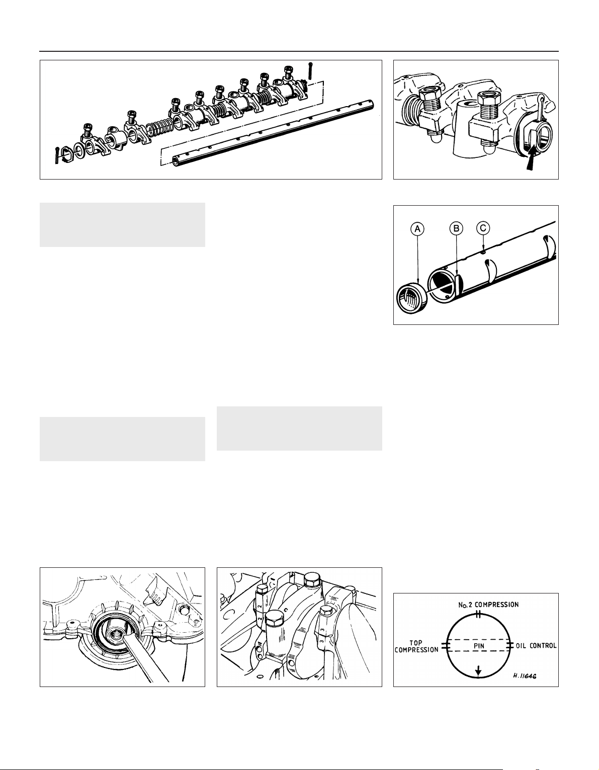
7 Rocker gear - dismantling
and reassembly
2
1 With the rocker assembly removed, extract
the split pin from one end of the rocker shaft.
2 Take off the spring and plain washers from
the end of the shaft.
3 Slide off the rocker arms, support pedestals
and coil springs, keeping them in their
originally fitted order (see illustration). Clean
out the oil holes in the shaft.
4 Apply engine oil to the rocker shaft before
reassembling and make sure that the flat on
the end of the shaft is to the same side as the
rocker arm adjuster screws (see illustration).
This is essential for proper lubrication of the
components.
5 If a new rocker shaft is being fitted, check
that the end plug is located correctly (see
illustration).
8 Crankshaft front oil seal -
renewal
3
1 Disconnect the battery earth cable.
2 Slacken the alternator mounting and
adjuster bolts and after pushing the alternator
in towards the engine, slip off the drivebelt.
3 Unscrew and remove the crankshaft pulley
bolt. To prevent the crankshaft turning while
the bolt is being released, jam the teeth of the
starter ring gear on the flywheel after
removing the clutch cover plate or starter
motor for access.
4 Remove the crankshaft pulley. This should
come out using the hands but, if it is tight,
prise it carefully with two levers placed at
opposite sides under the pulley flange.
5 Using a suitable claw tool, prise out the
defective seal and wipe out the seat (see
illustration).
6 Install the new seal using a suitable
distance piece, the pulley and its bolt to draw
it into position. If it is tapped into position, the
seal may be distorted or the timing cover
fractured.
7 When the seal is fully seated, remove the
pulley and bolt, apply grease to the seal
rubbing surface of the pulley, install it and
tighten the securing bolt to the specified
torque.
8 Refit the clutch cover or starter motor.
9 Fit and tension the drivebelt and reconnect
the battery.
9 Pistons/connecting rods -
removal and refitting
3
Removal
1 Remove the cylinder head and the sump.
Do not remove the oil pick-up filter or pipe,
which is an interference fit.
2 Note the location numbers stamped on the
connecting rod big-ends and caps, and to
which side they face (see illustration). No 1
assembly is nearest the timing cover and the
assembly numbers are towards the camshaft
side of the engine.
3 Turn the crankshaft by means of the pulley
bolt until the big-end cap bolts for No 1
connecting rod are in their most accessible
position. Unscrew and remove the bolts and
the big-end cap complete with bearing shell. If
the cap is difficult to remove, tap it off with a
plastic-faced hammer.
4 If the bearing shells are to be used again,
keep the shell taped to its cap.
5 Feel the top of the cylinder bore for a wear
ridge. If one is detected, it should be scraped
off before the piston/rod is pushed out of the
top of the cylinder block. Take care when doing
this not to score the cylinder bore surfaces.
6 Push the piston/connecting rod out of the
block, retaining the bearing shell with the rod
if it is to be used again.
7 Repeat the operations on the remaining
piston/rod assemblies.
Refitting
8 To install a piston/rod assembly, have the
piston ring gaps staggered as shown (see
illustration). Oil the rings and fit a piston ring
compressor.
2A•6 OHV engine repair procedures
7.3 Rocker components
7.5 Rocker shaft front end plug (A), flat (B)
and oil hole (C)
9.8 Piston ring end gap positioning
diagram
9.2 Connecting rod big-end numbers8.5 Prising out the crankshaft front oil seal
7.4 Flat on rocker shaft (arrowed) and
retaining pin
Page 25
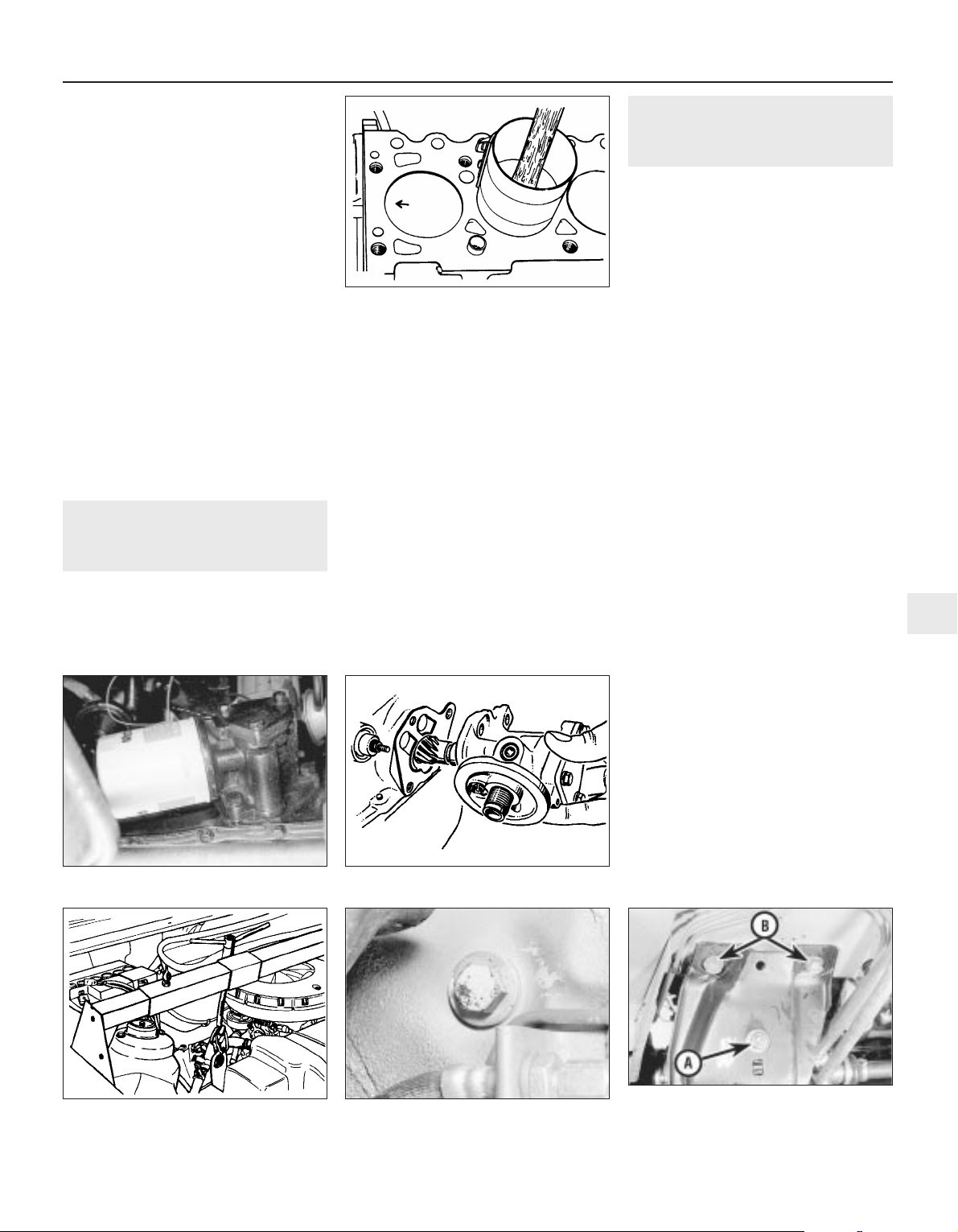
9 Oil the cylinder bores.
10 Wipe out the bearing shell seat in the
connecting rod and insert the shell.
11 Lower the piston/rod assembly into the
cylinder bore until the base of the piston ring
compressor stands squarely on the top of the
block (see illustration).
12 Check that the directional arrow on the
piston crown faces towards the timing cover
end of the engine and then apply the wooden
handle of a hammer to the piston crown.
Strike the head of the hammer sharply to drive
the piston into the cylinder bore.
13 Oil the crankpin and draw the connecting
rod down to engage with the crankshaft.
Check that the bearing shell is still in position
in the connecting rod.
14 Wipe the bearing shell seat in the big-end
cap clean and insert the bearing shell.
15 Fit the cap, screw in the bolts and tighten
to the specified torque.
16 Repeat the operations on the remaining
pistons/connecting rods.
17 Refit the sump and the cylinder head.
Refill with oil and coolant.
10 Oil filter and pump - removal
and refitting
2
Removal
1 The oil pump is externally mounted on the
rearward facing side of the crankcase (see
illustration).
2 Using a suitable removal tool (strap wrench
or similar), unscrew and remove the oil filter
cartridge and discard it.
3 Unscrew the three mounting bolts and
withdraw the oil pump from the engine (see
illustration).
4 Clean away the old gasket.
Refitting
5 If a new pump is being fitted, it should be
primed with engine oil before installation. Do
this by turning its shaft while filling it with
clean engine oil.
6 Locate a new gasket on the pump
mounting flange, insert the pump shaft and
bolt the pump into position.
7 Oil the rubber sealing ring of a new filter
and screw it into position on the pump, using
hand pressure only, not the removal tool.
8 Top-up the engine oil to replenish any lost
during the operations.
11 Engine/transmission
mountings - removal and
refitting
3
1 The engine mountings can be removed if
the weight of the engine/transmission is first
taken by one of the three following methods:
a) Support the engine under the sump
using a jack and a block of wood.
b) Attach a hoist to the engine lifting lugs.
c) Make up a bar with end pieces which will
engage in the water channels at the sides of
the bonnet lid aperture. Using an adjustable
hook and chain connected to the engine
lifting lugs, the weight of the engine can be
taken off the mountings (see illustration).
Right-hand engine mounting
2 Unscrew and remove the mounting side
bolt from under the right-hand wheel arch,
just to the rear of and above the brake hose
bracket (see illustration).
3 Unscrew and remove the mounting
retaining nut and washer from the suspension
strut cup retaining plate.
4 Undo the three bolts securing the mounting
unit to the cylinder block (working from
underneath). The mounting unit and bracket
can then be lowered from the engine.
5 Unbolt and remove the mounting from its
support bracket.
Engine bearer and mountings
6 Unscrew and remove the two nuts securing
each mounting (front and rear) to the engine
bearer.
7 Support the engine bearer, then undo and
remove the four retaining bolts from the
floorpan, two at the front and two at the rear
(see illustration).
8 Unscrew the retaining nut to disconnect the
rubber mounting from the transmission
support.
All mountings
9 Refitting of all mountings is a reversal of
removal. Make sure that the original sequence
of assembly of washers and plates is
maintained.
10 Do not fully tighten all mounting bolts until
they are all located. As the mounting bolts and
nuts are tightened, check that the mounting
rubbers do not twist.
OHV engine repair procedures 2A•7
10.3 Removing the oil pump
11.7 Engine bearer (rear end) showing
mounting retaining nut (A) and retaining
bolts to floor (B)
11.2 Right-hand engine mounting side
retaining bolt
11.1 Typical engine support bar
10.1 Oil filter and pump unit
9.11 Installing a piston/connecting rod
2A
Page 26
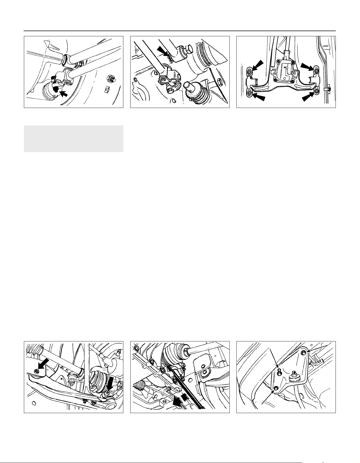
12 Engine/transmission -
removal and separation
4
Caution: After removing the engine, keep it
upright until the sump has been removed
to prevent sludge from entering the engine
internals.
Removal
1 This procedure entails lowering the engine
and gearbox, and removing the unit from
beneath the car. For this reason, certain items
of equipment are necessary. A suitable engine
hoist should be employed to lower the engine.
A more difficult alternative would be to use a
good trolley jack. Secondly, if an inspection
pit is not available, four strong axle jacks
capable of supporting the weight of the car,
must be used. In addition, a willing friend will
make the procedure easier.
2 Select 4th gear, or reverse gear on 5-speed
models, to make gearshift adjustment easier
on reassembly.
3 Open and remove the bonnet.
4 Disconnect the battery leads.
5 Drain the engine coolant.
6 Remove the radiator and thermo-electric
fan unit.
7 To drain any remaining coolant within the
engine, undo and remove the cylinder block
drain plug from the left-hand side at the front
(exhaust manifold face) and drain the
remaining coolant into a suitable container.
8 Disconnect the crankcase ventilation hoses
and remove the air cleaner unit.
9 Unclip and disconnect the heater hoses
from the inlet manifold connection and the
lateral coolant pipe.
10 Refer to Section 4 and proceed as
described in paragraphs 7 to 15 inclusive.
11 Disconnect the wiring connections from
the alternator, the carburettor, the inlet
manifold, the oil pressure switch, the
reversing light switch and the engine oil
dipstick (if applicable). Undo the securing bolt
and disconnect the engine earth strap.
12 Disconnect the speedometer drive cable
at the gearbox end.
13 Disconnect the clutch cable from the
release lever and gearbox support.
14 Raise and support the vehicle on safety
stands at the front and rear, ensuring that,
when raised, the vehicle is level and there is
sufficient clearance to lower and remove the
engine and transmission from underneath.
15 Disconnect the starter motor leads.
16 Disconnect the gearchange rod from the
gearbox selector shaft. Do this by releasing
the clamp bolt and withdrawing the rod (see
illustration). Tie the rod to the stabilizer and
then unhook the tension spring.
17 Unscrew the single bolt and disconnect
the stabilizer from the gearbox. Note the
washer which is located between the
stabilizer trunnion and the gearbox casing
(see illustration).
18 Drain the gearbox. As no drain plug is
fitted, this is carried out by unscrewing the
cap nut on the selector shaft locking
assembly. Take care not to lose the locking
pin and spring.
19 Undo and remove the four nuts retaining
the gearshift housing unit to the floor (see
illustration). Rotate the shift rod and stabilizer
180° and support them by tying them up with
a length of cord or wire.
20 Unscrew and remove the pivot bolt and
nut from the inboard end of the left side front
suspension lower arm (see illustration), then
remove the bolt which secures the balljoint at
the outboard end of the lower arm to the stub
axle carrier. An Allen key can be used to
prevent the bolt turning while the nut is
unscrewed.
21 The left-hand driveshaft must now be
released from the transmission. Do this by
inserting a lever between the inboard constant
velocity (CV) joint and the transmission (see
illustration). With an assistant pulling the
roadwheel outwards, strike the lever hard with
the hand. Note that a quantity of oil will be
released when the driveshaft is removed so
have a container ready.
22 Tie the driveshaft up to the steering rack
housing to prevent strain to the CV joints.
23 Restrain the differential pinion cage to
prevent the cage from turning, using a plastic
plug or similar. Failure to do this may make
reconnection of the driveshafts difficult.
24 Remove the three retaining bolts and
detach the tie-bar on the right-hand side,
complete with mounting bracket, from the
crossmember (see illustration).
25 Release the inboard and outboard ends of
the front suspension lower arm on the righthand side of the vehicle, as described for the
left-hand side.
2A•8 OHV engine repair procedures
12.16 Gearchange rod clamp bolt
(arrowed)
12.19 Gearshift housing unit-to-floor nuts
(arrowed)
12.24 Tie-bar mounting bolts (arrowed).
Note that XR2 variant differs
12.21 Driveshaft removal from gearbox12.20 Front suspension lower arm pivot
bolt and nut locations
12.17 Gearchange stabilizer rod
connection - arrow indicates washer
location
Page 27
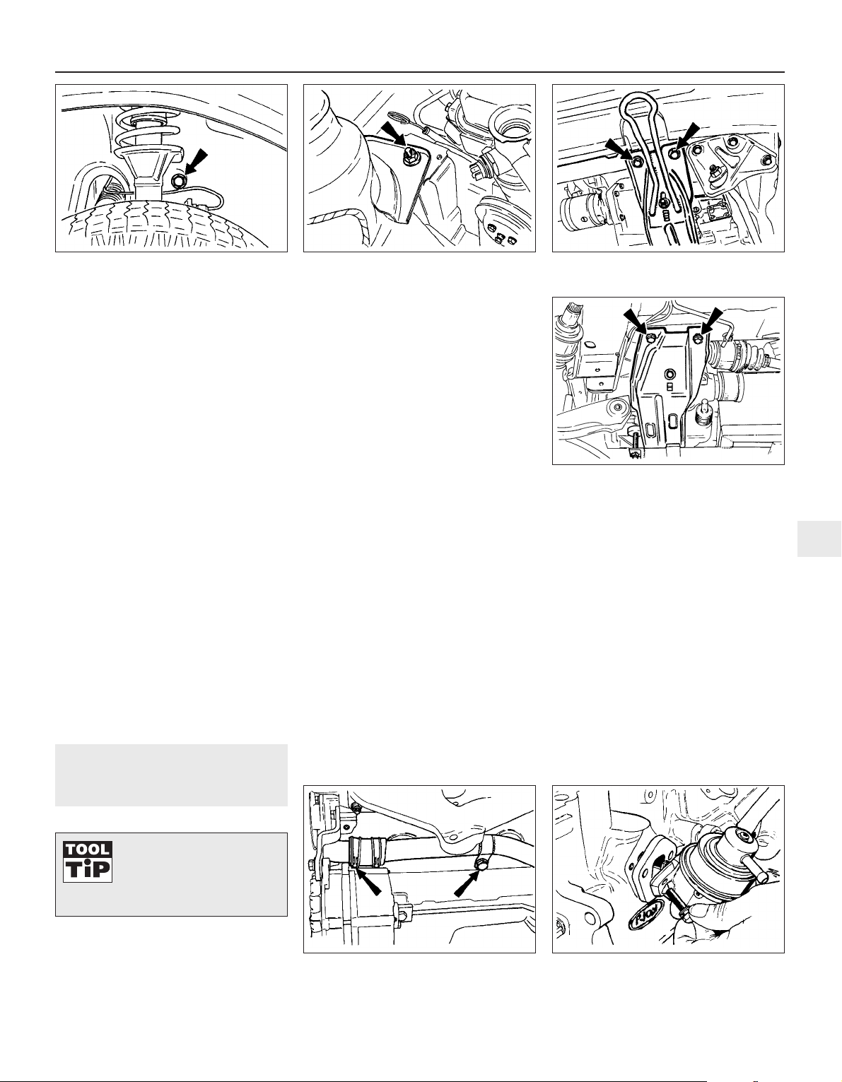
26 Disconnect the right-hand driveshaft, as
previously described for the left-hand one.
27 Connect a suitable hoist to the engine,
preferably using a spreader bar and
connecting lifting hooks to the engine: lifting
lugs provided.
28 With the weight of the engine and
transmission just supported, disconnect the
engine and transmission mountings at the
points shown (see illustrations).
29 Unbolt the engine mounting (complete
with coolant hose support bracket, where
applicable) from the side-member and from
the wing apron panel.
30 Carefully lower the engine/transmission
and withdraw it from under the car. To ease
the withdrawal operation, lower the
engine/transmission onto a crawler board or a
sheet of substantial plywood placed on rollers
or lengths of pipe.
Separation
31 Unscrew and remove the starter motor
bolts and remove the starter.
32 Unbolt and remove the clutch cover plate
from the lower part of the clutch bellhousing.
33 Unscrew and remove the bolts from the
clutch bellhousing-to-engine mating flange.
34 Withdraw the transmission from the
engine. Support its weight so that the clutch
assembly is not distorted while the input shaft
is still in engagement with the splined hub of
the clutch driven plate.
13 Engine - dismantling
4
1 The need for dismantling will have been
dictated by wear or noise in most cases.
Although there is no reason why only partial
dismantling cannot be carried out to renew
such items as the timing chain or crankshaft
rear oil seal, when the main bearings or bigend bearings have been knocking, and
especially if the vehicle has covered a high
mileage, then it is recommended that a
complete strip down is carried out and every
engine component examined.
2 Position the engine so that it is upright on a
bench or other convenient working surface. If
the exterior is very dirty it should be cleaned
before dismantling using paraffin and a stiff
brush or a water-soluble solvent.
3 Remove the coolant pipe from the side of
the engine by disconnecting the hose clips
and the securing bolt (see illustration).
4 If not already done, drain the engine oil.
5 Remove the dipstick and unscrew and
discard the oil filter.
6 Disconnect the HT leads from the spark
plugs, release the distributor cap and lift it
away complete with leads.
7 Unscrew and remove the spark plugs.
8 Disconnect the breather hose from the inlet
manifold and remove it complete with the oil
filler cap.
9 Disconnect the fuel and vacuum pipes from
the carburettor and unbolt and remove the
carburettor.
10 Unbolt the thermostat housing cover and
remove it, together with the thermostat.
11 Remove the rocker cover.
12 Remove the rocker shaft assembly (four
bolts).
13 Withdraw the pushrods, keeping them in
their originally fitted order.
14 Remove the cylinder head, complete with
manifolds.
15 Remove the bolt that holds the distributor
clamp plate to the cylinder block and
withdraw the distributor.
16 Unbolt and remove the fuel pump (see
illustration).
17 Remove the oil pump.
18 Pinch the two runs of the coolant pump
drivebelt together at the pump pulley to
prevent the pulley rotating and release the
pulley bolts.
19 Release the alternator mounting and
adjuster link bolts, push the alternator in
towards the engine and remove the drivebelt
(see illustration).
20 Unbolt the alternator bracket and remove
the alternator (see illustration).
21 Unbolt and remove the coolant pump
(see illustration).
OHV engine repair procedures 2A•9
12.28c Engine bearer retaining bolts front
13.16 Unbolt and remove the fuel pump13.3 Engine lateral coolant pipe
connections (arrowed)
12.28d Engine bearer retaining bolts - rear
12.28b Engine mounting nut on right-hand
suspension strut retaining plate (arrowed)
12.28a Engine mounting bolt under righthand wheel arch
2A
It is best to support an
engine on a dismantling
stand or strong bench at a
comfortable working height
before commencing work.
Page 28
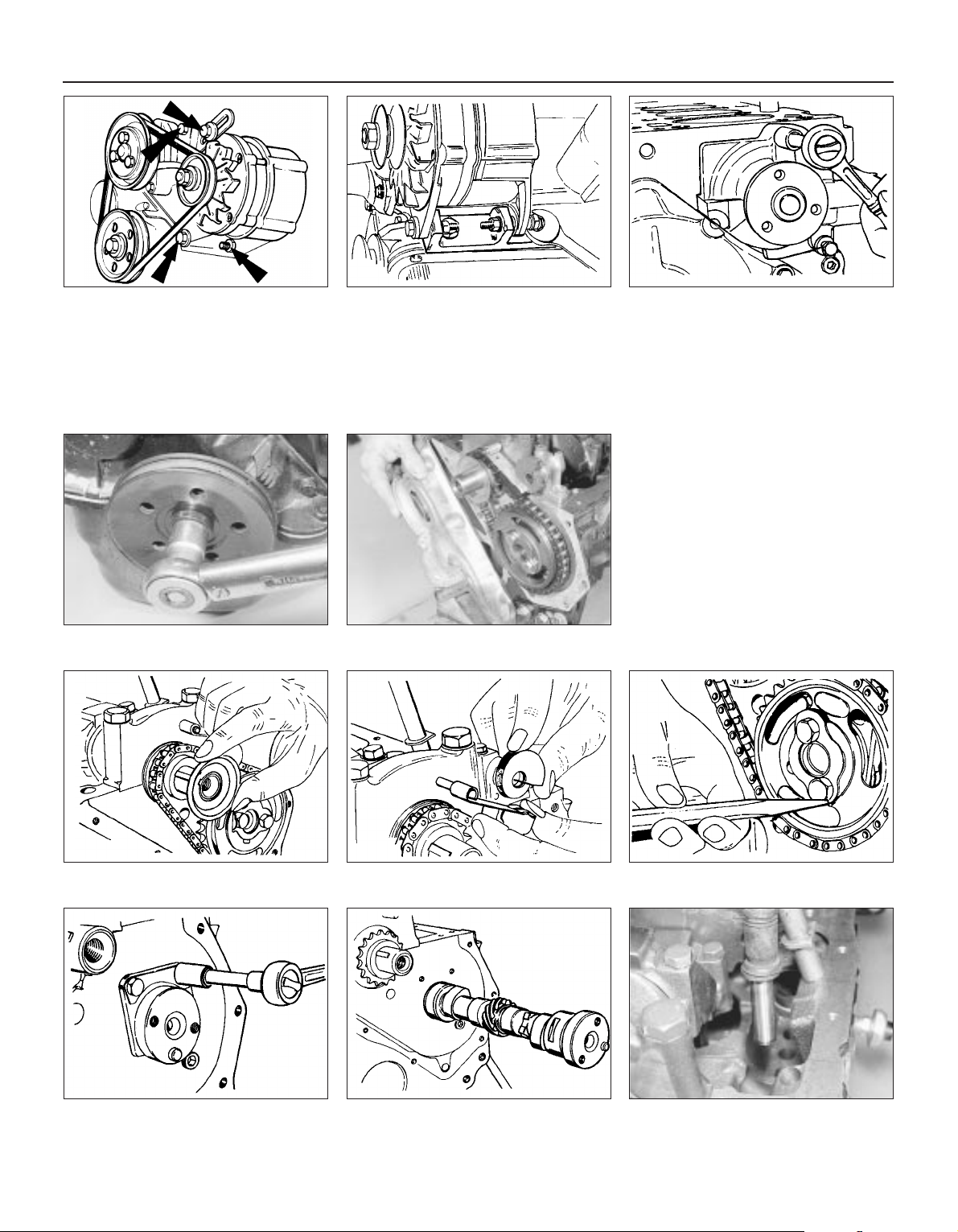
22 Unscrew the crankshaft pulley bolt. To do
this, the flywheel starter ring gear will have to
be jammed to prevent the crankshaft from
turning (see illustration).
23 Remove the crankshaft pulley. If this does
not pull off by hand, carefully use two levers
behind it placed at opposite points.
24 Place the engine on its side and remove the
sump. Do not invert the engine at this stage, or
sludge and swarf may enter the oilways.
25 Unbolt and remove the timing chain cover
(see illustration).
26 Take off the oil slinger from the front face
of the crankshaft sprocket (see illustration).
27 Slide the chain tensioner arm from its
pivot pin on the front main bearing cap (see
illustration).
28 Unbolt and remove the chain tensioner.
29 Bend back the lockplate tabs from the
camshaft sprocket bolts and unscrew and
remove the bolts (see illustration).
30 Withdraw the sprocket complete with
timing chain.
31 Unbolt and remove the camshaft thrust
plate (see illustration).
32 Rotate the camshaft until each cam
follower (tappet) has been pushed fully into its
hole by its cam lobe.
33 Withdraw the camshaft, taking care not to
damage the camshaft bearings (see illustration).
34 Withdraw each of the cam followers,
keeping them in their originally fitted
sequence by marking them with a piece of
numbered tape or using a box with divisions
(see illustration).
2A•10 OHV engine repair procedures
13.19 Alternator retaining and drivebelt
adjustment bolts
13.21 Unbolt and remove the coolant pump
13.34 Lift out the cam followers (tappets),
using a valve grinding tool
13.31 Unbolting the camshaft thrust plate
13.26 Removing the crankshaft oil slinger 13.27 Sliding off the chain tensioner arm 13.29 Bending back the camshaft
sprocket bolt locktabs
13.33 Withdrawing the camshaft
13.25 Remove the timing chain cover13.22 Unscrew the crankshaft pulley
retaining bolt
13.20 Alternator mounting bracket
Page 29

35 From the front end of the crankshaft, draw
off the sprocket using a two-legged extractor.
36 Check that the main bearing caps are
marked F (Front), C (Centre) and R (Rear). The
caps are also marked with an arrow which
indicates the timing cover end of the engine, a
point to remember when refitting the caps.
37 Check that the big-end caps and
connecting rods have adjacent matching
numbers facing towards the camshaft side of
the engine. Number 1 assembly is nearest the
timing chain end of the engine. If any
markings are missing or indistinct, make
some of your own with quick-drying paint
(see illustration).
38 Unbolt and remove the big-end bearing
caps. If the bearing shell is to be used again,
tape the shell to the cap.
39 Now check the top of the cylinder bore for
a wear ridge. If one can be felt, it should be
removed with a scraper before the piston/rod
is pushed out of the cylinder.
40 Remove the piston/rod by pushing it out
of the top of the block. Tape the bearing shell
to the connecting rod.
41 Remove the remaining three piston/rod
assemblies in a similar way.
42 Unbolt the clutch pressure plate cover
from the flywheel. Unscrew the bolts evenly
and progressively until spring pressure is
relieved, before removing the bolts. Be
prepared to catch the clutch driven plate as
the cover is withdrawn.
43 Unbolt and remove the flywheel. It is
heavy, do not drop it. If necessary, the starter
ring gear can be jammed to prevent the
flywheel rotating. There is no need to mark the
fitted position of the flywheel to its mounting
flange as it can only be fitted one way. Take
off the adapter plate (engine backplate).
44 Unbolt and remove the crankshaft rear oil
seal retainer (see illustration).
45 Unbolt the main bearing caps. Remove
the caps, tapping them off if necessary with a
plastic-faced hammer. Retain the bearing
shells with their respective caps if the shells
are to be used again, although unless the
engine is of low mileage this is not
recommended.
46 Lift the crankshaft from the crankcase and
lift out the upper bearing shells, noting the
thrustwashers either side of the centre
bearing. Keep these shells with their
respective caps, identifying them for refitting
to the crankcase if they are to be used again.
47 With the engine now completely
dismantled, each component should be
examined, as described in the following
Section before reassembling.
14 Engine - examination and
renovation
3
1 Clean all components using paraffin and a
stiff brush, except the crankshaft, which
should be wiped clean and the oil passages
cleaned out with a length of wire.
2 Never assume that a component is unworn
simply because it looks all right. After all the
effort which has gone into dismantling the
engine, refitting worn components will make
the overhaul a waste of time and money.
Depending on the degree of wear, the
overhauler’s budget and the anticipated life of
the vehicle, components which are only
slightly worn may be refitted, but if in doubt it
is always best to renew.
Crankshaft, main and big-end
bearings
3 The need to renew the main bearing shells
or to have the crankshaft reground will usually
have been determined during the last few
miles of operation when perhaps a heavy
knocking has developed from within the
crankcase or the oil pressure warning lamp
has stayed on, denoting a low oil pressure
probably caused by excessive wear in the
bearings.
4 Even without these symptoms, the journals
and crankpins on a high mileage engine
should be checked for out-of-round (ovality)
and taper. For this a micrometer will be
needed to check the diameter of the journals
and crankpins at several different points
around them. A motor factor or engineer can
do this for you. If the readings show that either
out-of-round or taper is present, then the
crankshaft should be reground by your dealer
or engine reconditioning company to accept
the undersize main and big-end shell bearings
which are available. Normally, the company
doing the regrinding will supply the necessary
undersize shells.
5 If the crankshaft is in good condition, it is
wise to renew the bearing shells as it is almost
certain that the original ones will have worn.
This is often indicated by scoring of the
bearing surface or by the top layer of the
bearing metal having worn through to expose
the metal underneath.
6 Each shell is marked on its back with the
part number. Undersize shells will have the
undersize stamped additionally on their
backs.
7 Standard size crankshafts having main
bearing journal diameters at the lower end of
the tolerance range are marked with a yellow
spot on the front balance weight. You will find
that with this type of crankshaft, a standard
shell is fitted to the seat in the crankcase but a
yellow colour-coded shell to the main bearing
cap.
8 If a green spot is seen on the crankshaft
then this indicates that 0.254 mm undersize
big-end bearings are used in place of the
standard diameter.
Cylinder bores, pistons, rings
and connecting rods
9 Cylinder bore wear will usually have been
evident from the smoke emitted from the
exhaust during recent operation of the vehicle
on the road, coupled with excessive oil
consumption and fouling of spark plugs.
10 Engine life can be extended by fitting
special oil control rings to the pistons. These
are widely advertised and will give many more
thousands of useful mileage without the need
for a rebore, although this will be inevitable
eventually. If this remedy is decided upon,
remove the piston/connecting rods and fit the
proprietary rings in accordance with the
manufacturer’s instructions.
11 Where a more permanent solution is
decided upon, the cylinder block can be
rebored by your dealer or engineering works,
or by one of the mobile workshops which now
undertake such work. The cylinder bore will
be measured both for out-of-round and for
taper to decide how much the bores should
be bored out. A set of matching pistons will
be supplied in a suitable oversize to suit the
new bores.
12 Due to the need for special heating and
installing equipment for removal and refitting
of the interference type gudgeon pin, the
removal and refitting of pistons to the
connecting rods is definitely a specialist job,
preferably for your Ford dealer.
13 The removal and refitting of piston rings is
however well within the scope of the home
mechanic. Do this by sliding two or three old
feeler blades round behind the top
compression ring so that they are at
equidistant points. The ring can now be slid
up the blades and removed. Repeat the
removal operations on the second
compression ring and then the oil control ring.
This method will not only prevent the rings
from dropping onto empty grooves as they
are withdrawn, but it will also avoid ring
breakage.
OHV engine repair procedures 2A•11
13.44 Crankshaft rear oil seal retainer13.37 Connecting rod and big-end cap
markings (arrowed)
2A
Page 30
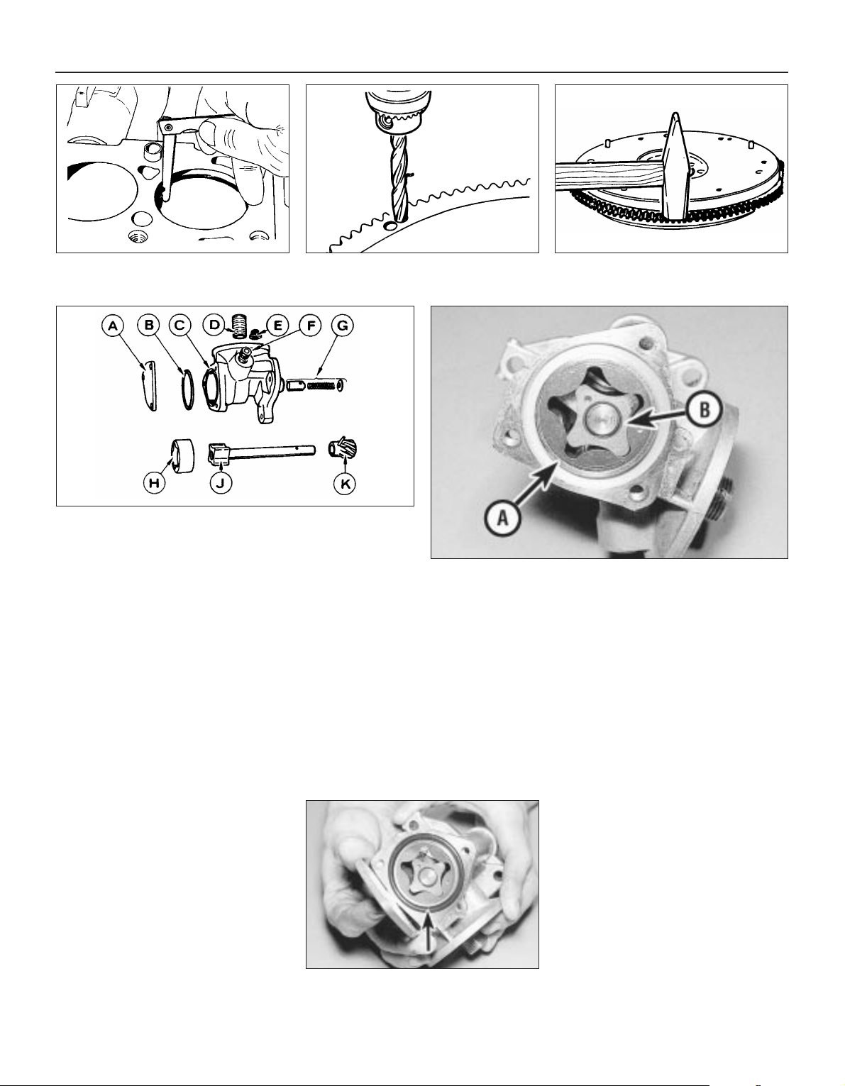
14 Even when new piston rings have been
supplied to match the pistons, always check
that they are not tight in their grooves and
also check their end gaps by pushing them
squarely down their particular cylinder bore
and measuring with a feeler blade (see
illustration). Adjustment of the end gap can
be made by careful grinding to bring it within
the specified tolerance.
15 If new rings are being fitted to an old
piston, always remove any carbon from the
grooves beforehand. The best tool for this job
is the end of a broken piston ring. Take care
not to cut your fingers, piston rings are sharp.
The cylinder bores should be roughened with
fine glass paper to assist the bedding-in of the
new rings.
Timing sprockets and chain
16 The teeth on the timing sprockets rarely
wear, but check for broken or hooked teeth
even so.
17 The timing chain should always be
renewed at time of major engine overhaul. A
worn chain is evident if, when supported
horizontally at both ends, it takes on a deeply
bowed appearance.
18 Finally check the rubber cushion on the
tensioner spring leaf. If grooved or chewed
up, renew it.
Flywheel
19 Inspect the starter ring gear on the
flywheel for wear or broken teeth. If evident,
the ring gear should be renewed in the
following way. Drill the ring gear with two
holes, approximately 7 or 8 mm diameter and
offset as shown (see illustration). Make sure
that you do not drill too deeply or you will
damage the flywheel.
20 Tap the ring gear downward off its
register and remove it (see illustration).
21 Place the flywheel in the household
refrigerator for about an hour and then heat
the new ring gear to between 260 and 28°C in
a domestic oven. Do not heat it above 290°C
or its hardness will be lost.
22 Slip the ring onto the flywheel and gently
tap it into position against its register. Allow it
to cool without quenching.
23 The clutch friction surface on the flywheel
should be checked for grooving or tiny hair
cracks, the latter being caused by
overheating. If these conditions are evident, it
may be possible to surface grind the flywheel
provided its balance is not upset. Otherwise, a
new flywheel will have to be fitted - consult
your dealer about this.
Oil pump
24 The oil pump should be checked for wear
by unbolting and removing the cover plate
and checking the following tolerances (see
illustrations).
a) Outer rotor-to-pump body gap
b) Inner rotor-to-outer rotor gap
c) Rotor endfloat (use a feeler blade and
straight-edge across pump body)
Use feeler blades to check the tolerances and
if they are outside the specified values, renew
the pump.
25 If the pump is serviceable, renew the Oring and refit the cover (see illustration).
2A•12 OHV engine repair procedures
14.14 Checking a piston ring end gap 14.20 Removing the ring gear from the
flywheel
14.24b Check the oil pump rotor-to-body clearance at (a) and the
inner-to-outer rotor clearance at (b)
14.24a Oil pump components
A Cover
B O-ring
C Pump body
D Threaded insert
E Filter (relief valve)
F Plug
G Relief valve
H Outer rotor
J Inner rotor
K Drive pinion
14.19 Drilling the flywheel starter ring gear
14.25 Oil pump O-ring seal must be
renewed (arrowed)
Page 31

Oil seals and gasket
26 Renew the oil seals on the timing cover
and the crankshaft rear retainer as a matter of
routine at time of major overhaul. Oil seals are
cheap, oil is not! Use a piece of tubing as a
removal and installing tool. Apply some
grease to the oil seal lips and check that the
small tensioner spring in the oil seal has not
been displaced by the vibration caused during
fitting of the seal.
27 Renew all the gaskets by purchasing the
appropriate “de-coke”, short or full engine
set. Oil seals may be included in the gasket
sets.
Crankcase
28 Clean out the oilways with a length of wire
or by using compressed air. Similarly clean
the coolant passages. This is best done by
flushing through with a cold water hose.
Examine the crankcase and block for stripped
threads in bolt holes; if evident, thread inserts
can be fitted.
29 Renew any core plugs which appear to be
leaking or which are excessively rusty.
30 Cracks in the casting may be rectified by
specialist welding, or by one of the cold metal
key interlocking processes available.
Camshaft and bearings
31 Examine the camshaft gear and lobes for
damage or wear. If evident a new camshaft
must be purchased, or one which has been
built-up such as are advertised by firms
specialising in exchange components.
32 The bearing internal diameters should be
checked against the Specifications if a
suitable gauge is available: otherwise, check
for movement between the camshaft journal
and the bearing. Worn bearings should be
renewed by your dealer.
33 Check the camshaft endfloat by
temporarily refitting the camshaft and the
thrust plate.
Cam followers
34 It is seldom that the cam followers wear in
their bores, but it is likely that after a high
mileage, the cam lobe contact surface will
show signs of a depression or grooving.
35 Where this condition is evident, renew the
cam followers. Grinding out the wear marks
will only reduce the thickness of the hardened
metal of the cam follower and accelerate
further wear.
Cylinder head and rocker gear
36 The usual reason for dismantling the
cylinder head is to decarbonise and to grind in
the valves. Reference should therefore be
made to the next Section, in addition to the
dismantling operations described here. First
remove the manifolds.
37 Using a standard valve spring
compressor, compress the spring on No 1
valve (valve nearest the timing cover). Do not
overcompress the spring or the valve stem
may bend. If it is found that, when screwing
down the compressor tool, the spring retainer
does not release from the collets, remove the
compressor and place a piece of tubing on
the retainer so that it does not impinge on the
collets and strike the end of the tubing a sharp
blow with a hammer. Refit the compressor
and compress the spring.
38 Extract the split collets and then gently
release the compressor and remove it.
39 Remove the valve spring retainer, the
spring and the oil seal.
40 Withdraw the valve.
41 Repeat the removal operations on the
remaining seven valves. Keep the valves in
their originally fitted sequence by placing
them in 3 piece of card which has holes
punched in it and numbered 1 to 8 (from the
timing cover end).
42 Place each valve in turn in its guide so
that approximately one third of its length
enters the guide. Rock the valve from side to
side (see illustration). If there is any more
than an imperceptible movement, the guides
will have to be reamed (working from the valve
seat end) and oversize stemmed valves fitted.
If you do not have the necessary reamer (tool
71-042 or 21-043), leave this work to your
Ford dealer.
43 Examine the valve seats. Normally, the
seats do not deteriorate but the valve heads
are more likely to burn away, in which case
new valves can be ground in. If the seats
require re-cutting, use a standard cutter
available from most accessory or tool stores
or consult your motor engineering works.
44 Renewal of any valve seat which is
cracked or beyond recutting is definitely a job
for your dealer or motor engineering works.
45 If the cylinder head mating surface is
suspected of being distorted due to persistent
leakage of coolant at the gasket joint, then it
can be checked and surface ground by your
dealer or motor engineering works. Distortion
is unlikely under normal circumstances with a
cast iron head.
46 Check the rocker shaft and rocker arms
pads which bear on the valve stem end faces
for wear or scoring, also for any broken coil
springs. Renew components as necessary. If
the valve springs have been in use for 50 000
miles (80 000 km) or more, they should be
renewed.
47 Reassemble the cylinder head by first
fitting new valve stem oil seals (see
illustration). Install No 1 valve (lubricated) into
its guide and fit the valve spring with the
closer coils to the cylinder head, followed by
the spring retainer. Compress the spring and
engage the split collets in the cutout in the
valve stem. Hold them in position while the
compressor is gently released and removed.
48 Repeat the operations on the remaining
valves, making sure that each valve is
returned to its original guide or if new valves
have been fitted, into the seat into which it
was ground.
49 On completion, support the ends of the
cylinder head on two wooden blocks and
strike the end of each valve stem with a
plastic or copper-faced hammer; just a light
blow to settle the components.
15 Cylinder head and pistons -
decarbonising
3
1 With the cylinder head removed, the carbon
deposits should be removed from the
combustion spaces using a scraper and a
wire brush fitted into an electric drill. Take
care not to damage the valve heads,
otherwise no special precautions need be
taken as the cylinder head is of cast iron
construction.
2 Where a more thorough job is to be carried
out, the cylinder head should be dismantled
so that the valves may be ground in and the
ports and combustion spaces cleaned,
brushed and blown out after the manifolds
have been removed.
3 Before grinding-in a valve remove the
carbon and deposits completely from its head
and stem. With an inlet valve, this is usually
quite easy, simply scraping off the soft carbon
with a blunt knife and finishing with a wire
brush. With an exhaust valve the deposits are
very much harder and those on the head may
need a rub on coarse emery cloth to remove
them. An old woodworking chisel is a useful
tool to remove the worst of the head deposits.
4 Make sure that the valve heads are really
clean, otherwise the rubber suction cup of the
grinding tool will not stick during the grindingin operations.
OHV engine repair procedures 2A•13
14.47 Valve stem oil seals
A Exhaust valve type B Inlet valve type
14.42 Checking valve in guide for wear
2A
Page 32

5 Before starting to grind in a valve, support
the cylinder head so that there is sufficient
clearance under for the valve stem to project
fully without being obstructed.
6 Take the first valve and apply a little coarse
grinding paste to the bevelled edge of the
valve head. Insert the valve into its guide and
apply the suction grinding tool to its head
(see illustration). Rotate the tool between the
palms of the hands in a back-and-forth rotary
movement until the gritty action of the
grinding-in process disappears. Repeat the
operation with the fine paste and then wipe
away all traces of grinding paste and examine
the seat and bevelled edge of the valve. A
matt silver mating band should be observed
on both components, without any sign of
black spots. If some spots do remain, repeat
the grinding-in process until they have
disappeared. A drop or two of paraffin applied
to the contact surfaces will increase the
speed of grinding-in, but do not allow any
paste to run down into the valve guide. On
completion, wipe away every trace of grinding
paste using a paraffin-moistened cloth.
7 Repeat the operations on the remaining
valves, taking care not to mix up their
originally fitted sequence.
8 Reassemble the valves to the cylinder head.
9 An important part of the decarbonising
operation is to remove the carbon deposits
from the piston crowns. To do this, turn the
crankshaft so that two pistons are at the top
of their stroke and press some grease
between these pistons and the cylinder walls.
This will prevent carbon particles falling down
into the piston ring grooves. Stuff rags into the
other two bores.
10 Cover the oilways and coolant passages
with masking tape and then using a blunt
scraper remove all the carbon from the piston
crowns. Take care not to score the soft alloy
of the crown or the surface of the cylinder
bore.
11 Rotate the crankshaft to bring the other
two pistons to TDC and repeat the operations.
12 Wipe away the circle of grease and
carbon from the cylinder bores.
13 Clean the top surface of the cylinder block
by careful scraping.
16 Engine - reassembly
3
1 With everything clean, commence
reassembly by oiling the bores for the cam
followers and inserting them fully in their
original sequence.
2 Lubricate the camshaft bearings and insert
the camshaft from the timing cover end of the
engine.
3 Fit the thrust plate and tighten the fixing
bolts to the specified torque. The endfloat will
already have been checked, as described in
Section 14.
4 Wipe clean the main bearing shell seats in
the crankcase and fit the shells, noting that
the lower shells do not have the lubrication
groove. Using a little grease, stick the semicircular thrustwashers on either side of the
centre bearing so that the oil grooves are
visible when the washers are installed (see
illustrations).
5 Check that the Woodruff key is in position
on the front end of the crankshaft and tap the
crankshaft sprocket into place using a piece
of tubing.
6 Oil the bearing shells and lower the
crankshaft into the crankcase.
7 Wipe the seats in the main bearing caps
and fit the bearing shells into them. Install the
caps so that their markings are correctly
positioned (see illustration).
8 Screw in the cap bolts and tighten evenly to
the specified torque.
9 Now check the crankshaft endfloat. Ideally a
dial gauge should be used, but feeler blades are
an alternative if inserted between the face of the
thrustwasher and the machined surface of the
crankshaft balance weight after having prised
the crankshaft first in one direction and then the
other (see illustration). Provided the
thrustwashers at the centre bearing have been
renewed, the endfloat should be with the
specified tolerance. If it is not, oversize
thrustwashers are available (see Specifications).
10 Rotate the crankshaft so that the timing
mark on its sprocket is directly in line with the
centre of the crankshaft sprocket mounting
flange.
11 Engage the camshaft sprocket within the
timing chain and then engage the chain
around the teeth of the crankshaft sprocket.
Push the camshaft sprocket onto its mounting
flange. The camshaft sprocket bolt holes
should now be in alignment with the tapped
holes in the camshaft flange and both
sprocket timing marks in alignment (see
illustration). Turn the camshaft as necessary
2A•14 OHV engine repair procedures
15.6 Grinding-in a valve 16.4b Fit the upper main bearing shell
(with lubrication groove) and the
thrustwashers (centre bearing)
16.11 Crankshaft and camshaft sprocket
timing marks (arrowed)
16.9 Checking the crankshaft endfloat
using the dial gauge method
16.7 Main bearing cap markings
16.4a Crankshaft endfloat half
thrustwashers
Page 33

to achieve this, also withdraw the camshaft
sprocket and reposition it within the loop of
the chain. This is a “trial and error” operation
which must be continued until exact
alignment of bolt holes and timing marks is
achieved.
12 Screw in the sprocket bolts to the
specified torque and bend up the tabs of a
new lockplate (see illustration).
13 Bolt the timing chain tensioner into
position, retract the tensioner cam spring and
then slide the tensioner arm onto its pivot pin.
Release the cam tensioner so that it bears
upon the arm.
14 Fit the oil slinger to the front of the
crankshaft sprocket so that its convex side is
against the sprocket.
15 Using a new gasket, fit the timing cover
which will already have been fitted with a new
oil seal. One fixing bolt should be left out at
this stage as it also holds the coolant pump
(see illustration). Grease the oil seal lips and
fit the crankshaft pulley. Tighten the pulley
bolt to the specified torque.
16 Using a new gasket, bolt the crankshaft
rear oil seal retainer into position. Tighten the
bolts to the specified torque (see illustration).
17 Locate the engine adapter (back) plate on
its dowels and then fit the flywheel (see
illustration).
18 Screw in and tighten the flywheel bolts to
the specified torque. To prevent the flywheel
turning, the starter ring gear can be jammed
or a piece of wood placed between a
crankshaft balance weight and the inside of
the crankcase.
19 Install and centralise the clutch.
20 The pistons/connecting rods should now
be installed. Check to ensure that with the
piston crown arrow pointing to the timing
cover end of the engine, the oil hole in the
connecting rod is on the left as shown (see
illustration). Oil the cylinder bores.
21 Install the pistons/connecting rods.
22 Fit the sump.
23 Fit the oil pressure sender unit, if
removed.
24 Turn the crankshaft until No 1 piston is at
TDC (crankshaft pulley and timing cover
marks aligned) and fit the oil pump complete
with new gasket and a new oil filter.
25 Using a new gasket, fit the fuel pump. If
the insulating block became detached from
the crankcase during removal, make sure that
a new gasket is fitted to each side of the
block.
26 Fit the coolant pump using a new gasket.
27 Fit the cylinder head.
28 Refit the pushrods in their original
sequence, and the rocker shaft.
29 Adjust the valve clearances and refit the
rocker cover using a new gasket.
30 Fit the inlet and exhaust manifolds using
new gaskets and tightening the nuts and bolts
to the specified torque.
31 Refit the carburettor using a new flange
gasket and connect the fuel pipe from the
pump.
32 Screw in the spark plugs and the coolant
temperature switch (if removed).
33 Refit the thermostat and the thermostat
housing cover.
34 Fit the pulley to the coolant pump pulley
flange.
35 Fit the alternator and the drivebelt and
tension the belt.
36 Refit the distributor.
37 Refit the distributor cap and reconnect the
spark plug HT leads.
38 Bolt on and connect the coolant pipe to
the side of the cylinder block.
39 Fit the breather pipe from the oil filler cap
to the inlet manifold and fit the cap.
40 Check the sump drain plug for tightness.
A new seal should be fitted at regular intervals
to prevent leakage. Refit the dipstick.
41 Refilling with oil should be left until the
engine is installed in the vehicle.
17 Engine/transmission -
reconnection and refitting
4
1 This is a direct reversal of the removal and
separation from the transmission. Take care
not to damage the engine ancillary
components and body panels when raising
the unit into position.
Reconnection
2 Reconnection of the engine and
transmission is a reversal of separation but if
the clutch has been dismantled, check that
the driven plate has been centralised, and that
the pressure plate bolts are tightened to the
specified torque (see Chapter 6).
3 Locate the engine bearer and mountings
and tighten the attachment bolts and nuts.
Refitting
4 First check that the engine sump drain plug
is tight and that the gearbox cap nut (removed
to drain the oil) is refitted, together with its
locking pin and spring.
OHV engine repair procedures 2A•15
16.16 Refit the crankshaft rear oil seal
retainer - note new gasket
16.20 Piston-to-connecting rod
relationship. Lubrication hole and piston
crown mark (arrowed) must align as
shown
16.17 Locate the engine backplate over
the two dowels (arrowed)
16.15 Bolt (arrowed) which secures timing
cover and coolant pump
16.12 Secure the camshaft sprocket
retaining bolts with the tab washer
2A
Warning: Before starting a
newly installed engine, make a
final check to ensure that all
engine components have been
reconnected and that no rags or tools
have been left in the engine bay.
Page 34

5 Manoeuvre the engine/transmission under
the vehicle and attach the lifting hoist. Raise
the engine carefully until the engine mounting
stud is engaged in the suspension strut
retaining plate and the engine bearer is in
contact with the floorpan. Align the engine
bearer with the retaining bolt holes then fit
and tighten the bolts. When tightening the
bolts check that the mounting rubbers are not
being twisted (see illustration).
6 Refit the transmission bearer to the rubber
insulator, fit the right-hand mounting retaining
nut and washer, the side-mounted bolt and
washer (under the wheel arch) and tighten.
7 With the engine and transmission fully
secured, release the lifting hoist and remove
it.
8 If some sort of plug was used to prevent the
differential pinion cage from turning, remove
the plug now. If a plug was not used, insert a
finger in the driveshaft hole and align the cage
ready to receive the driveshaft. If this is not
done, the driveshaft cannot engage with the
splined pinion gear. Use a new snap-ring and
reconnect the right-hand driveshaft to the
transmission by having an assistant apply
pressure on the roadwheel. Check that the
snap-ring has locked in position.
9 Relocate the right-hand tie-bar and bracket
to the crossmember and refit the retaining
bolts.
10 Reconnect the right-hand lower
suspension arm. Tighten the bolts.
11 Refit the driveshaft and suspension lower
arm to the opposite side in a similar way to
that just described.
12 Rotate the gearchange housing back
through 180° then loosely attach it to the floor
panels with the retaining bolts.
13 Reconnect the transmission stabilizer rod,
making sure to insert the washer between the
rod and the transmission case (see
illustration).
14 Check that the gearchange rod is still in
4th (4-speed gearbox) or reverse (5-speed
gearbox).
15 Tighten the gearbox housing-to-floor
attachment bolts.
16 Check that the contact faces of the
gearchange rod and selector shaft are free of
grease then reconnect them and adjust as
follows, according to gearbox type:
Four-speed gearbox - pre 1987
models
a) Pull downwards on the gearchange rod
and slip it onto the selector shaft which
projects from the transmission. The clamp
should be loose on the gearchange rod
(see illustration).
b) Using a 3.5 mm diameter rod or pin,
insert it as shown and pull the gear lever
downwards to lock it in the selector slide.
When inserting the rod, point up upward
to feel the cut-out in the gear lever before
prising it downwards (see illustration).
Now turn your attention to the gearbox.
c) Using a pin or rod, inserted into the hole
in the end of the projecting selector shaft,
turn the shaft clockwise to its stop and
retain it in this position with a strong
rubber band. Now tighten the clamp
pinch-bolt (see illustration).
d) Remove the locking pins.
Four-speed gearbox - post February
1987 models
a) Set the gearchange lever inside the car to
2nd gear.
b) Free the control rod (which runs from the
floor lever) from the selector rod at the
transmission, by unscrewing the clamp
bolt.
c) Make up a stepped rod similar to the one
shown (see illustration). This can be
achieved by pushing a piece of welding
rod through a length of plastic tubing.
d) Insert the tool into the left-hand side of
the mechanism housing under the car,
and feel the point of the tool engage in
the hole in the lever arm. Fit the O-ring or
heavy rubber band as shown (see
illustration).
2A•16 OHV engine repair procedures
17.5 Engine bearer and mountings 17.16a Sliding the clamp onto the gearbox
selector shaft
17.16c Tightening the gearchange rod
clamp bolt
17.16b Gear lever locked in selector
housing by pin (arrowed)
17.13 Connect the gearbox stabilizer rod
17.16d Gearshift setting
tool
A Tubing
B Welding rod
C O-ring or rubber band
All dimensions in mm
Page 35

e) With 2nd gear correctly engaged,
reconnect the control rod to the selector
rod by tightening the clamp bolt. Remove
the stepped tool.
f) Select each gear in turn to confirm that
the linkage has been correctly set.
Five-speed gearbox - pre 1987 models
a) Use a lock tool similar to that shown, pull
the gear lever down in its selector gate
reverse gear position and set the tool to
hold it against the stop (see illustration).
b) Insert a suitable rod or drift into the hole
in the selector shaft, rotate the shaft
clockwise until it is felt to be against the
stop then push it into the gearbox and
retain it in this position while tightening
the gearchange rod clamp bolt. Remove
the drift and lock tool (see illustration).
Five-speed gearbox - post February
1987 models
a) Set the gearchange lever inside the car to
4th gear.
b) Release the control rod (which runs from
the floor lever) from the selector rod at the
transmission by unscrewing the clamp
bolt.
c) Insert a rod (3.5 mm diameter) into the
left-hand side of the mechanism housing
under the car (see illustration).
d) With the 4th gear correctly engaged,
reconnect the control rod to the selector
rod by tightening the clamp bolt. Remove
the temporary rod.
e) Select each gear in turn to confirm that
the linkage has been correctly set.
17 Refit the clutch housing cover plate and
secure with retaining bolts.
18 Refit the starter motor and reconnect its
wiring.
19 Reconnect the engine earth strap
underneath also the reversing light lead.
20 Refit the exhaust system and bolt the
downpipe to the manifold. Refit the heated air
box which connects with the air cleaner.
21 Reconnect the clutch operating cable.
22 Reconnect the electrical leads, the fuel
pipe, the brake vacuum hose and the
speedometer cable.
23 Reconnect the throttle cable and the
heater hoses.
24 Reconnect the radiator coolant hoses.
25 Fill up with engine oil, gearbox oil and
coolant, then reconnect the battery.
26 Refit the bonnet, bolting the hinges to
their originally marked positions.
27 Fit the air cleaner and reconnect the
hoses and the air cleaner inlet spout.
28 Once the engine is running, check the
dwell angle, timing, idle speed and mixture
adjustment.
29 If a number of new internal components
have been installed, run the vehicle at
restricted speed for the first few hundred
miles to allow time for the new components to
bed in. It is also recommended that with a
new or rebuilt engine, the engine oil and filter
are changed at the end of the running-in
period.
OHV engine repair procedures 2A•17
17.16g Retain selector shaft when
tightening clamp bolt
17.16h Setting tool in place - 5-speed
gearbox
17.16f Hold gear lever in position with lock
tool
17.16e Setting tool in place - 4-speed
gearbox
2A
Page 36

2A•18 Notes
Page 37

2B
1.3 and 1.6 litre engines
General
Engine type . . . . . . . . . . . . . . . . . . . . . . . . . . . . . . . . . . . . . . . . . . . . . . . Four-cylinder, overhead cam, water-cooled. Compound Valve
Hemispherical head (CVH)
1.3 litre 1.6 litre
Code . . . . . . . . . . . . . . . . . . . . . . . . . . . . . . . . . . . . . . . . . . . . . . . . . . . . JPC LUB
Firing order (No 1 at timing cover end) . . . . . . . . . . . . . . . . . . . . . . . . . . 1-3-4-2 1-3-4-2
Bore . . . . . . . . . . . . . . . . . . . . . . . . . . . . . . . . . . . . . . . . . . . . . . . . . . . . 79.96 mm 79.96 mm
Stroke . . . . . . . . . . . . . . . . . . . . . . . . . . . . . . . . . . . . . . . . . . . . . . . . . . . 64.52 mm 79.52 mm
Cubic capacity . . . . . . . . . . . . . . . . . . . . . . . . . . . . . . . . . . . . . . . . . . . . 1296 cc 1597 cc
Compression ratio . . . . . . . . . . . . . . . . . . . . . . . . . . . . . . . . . . . . . . . . . 9.5 : 1 9.5 : 1
Compression pressure at starter speed . . . . . . . . . . . . . . . . . . . . . . . . . 11.2 to 14.8 kgf/cm
2
11.2 to 14.8 kgf/cm
2
Maximum continuous engine speed (rpm) . . . . . . . . . . . . . . . . . . . . . . . 6450 6300
Cylinder block
Number of main bearings . . . . . . . . . . . . . . . . . . . . . . . . . . . . . . . . . . . . 5
Cylinder bore diameter:
Standard (1) . . . . . . . . . . . . . . . . . . . . . . . . . . . . . . . . . . . . . . . . . . . . 79.94 to 79.95 mm
Standard (2) . . . . . . . . . . . . . . . . . . . . . . . . . . . . . . . . . . . . . . . . . . . . 79.95 to 79.96 mm
Standard (3) . . . . . . . . . . . . . . . . . . . . . . . . . . . . . . . . . . . . . . . . . . . . 79.96 to 79.97 mm
Standard (4) . . . . . . . . . . . . . . . . . . . . . . . . . . . . . . . . . . . . . . . . . . . . 79.97 to 79.98 mm
Oversize (A) . . . . . . . . . . . . . . . . . . . . . . . . . . . . . . . . . . . . . . . . . . . . . 80.23 to 80.24 mm
Oversize (B) . . . . . . . . . . . . . . . . . . . . . . . . . . . . . . . . . . . . . . . . . . . . . 80.24 to 80.25 mm
Oversize (C) . . . . . . . . . . . . . . . . . . . . . . . . . . . . . . . . . . . . . . . . . . . . . 80.25 to 80.26 mm
Main bearing shell inner diameter:
Standard . . . . . . . . . . . . . . . . . . . . . . . . . . . . . . . . . . . . . . . . . . . . . . . 58.011 to 58.038 mm
Undersize 0.25 . . . . . . . . . . . . . . . . . . . . . . . . . . . . . . . . . . . . . . . . . . 57.761 to 57.788 mm
Undersize 0.50 . . . . . . . . . . . . . . . . . . . . . . . . . . . . . . . . . . . . . . . . . . 57.511 to 57.538 mm
Undersize 0.75 . . . . . . . . . . . . . . . . . . . . . . . . . . . . . . . . . . . . . . . . . . 57.261 to 57.288 mm
Crankshaft
Main bearing journal diameter:
Standard . . . . . . . . . . . . . . . . . . . . . . . . . . . . . . . . . . . . . . . . . . . . . . . 57.98 to 58.00 mm
Undersize 0.25 . . . . . . . . . . . . . . . . . . . . . . . . . . . . . . . . . . . . . . . . . . 57.73 to 57.75 mm
Undersize 0.50 . . . . . . . . . . . . . . . . . . . . . . . . . . . . . . . . . . . . . . . . . . 57.48 to 57.50 mm
Undersize 0.75 . . . . . . . . . . . . . . . . . . . . . . . . . . . . . . . . . . . . . . . . . . 57.23 to 57.25 mm
Chapter 2 Part B:
CVH engine repair procedures
Camshaft - removal and refitting . . . . . . . . . . . . . . . . . . . . . . . . . . . . .6
Camshaft oil seal - renewal . . . . . . . . . . . . . . . . . . . . . . . . . . . . . . . . .5
Crankshaft front oil seal - renewal . . . . . . . . . . . . . . . . . . . . . . . . . . . .8
Cylinder head - removal and refitting . . . . . . . . . . . . . . . . . . . . . . . . . .7
Cylinder head and pistons - decarbonising . . . . . . . . . . . . . . . . . . . .16
Engine - dismantling . . . . . . . . . . . . . . . . . . . . . . . . . . . . . . . . . . . . . .14
Engine - examination and renovation . . . . . . . . . . . . . . . . . . . . . . . . .15
Engine - reassembly . . . . . . . . . . . . . . . . . . . . . . . . . . . . . . . . . . . . . .17
Engine/transmission mountings - removal and refitting . . . . . . . . . . .11
Engine/transmission - reconnection and refitting . . . . . . . . . . . . . . . .18
Engine/transmission - removal and separation . . . . . . . . . . . . . . . . .13
General information . . . . . . . . . . . . . . . . . . . . . . . . . . . . . . . . . . . . . . .1
Oil filter - renewal . . . . . . . . . . . . . . . . . . . . . . . . . . . . . . . . . . . . . . . .12
Operations only possible with engine removed from vehicle . . . . . . . .3
Operations possible without removing engine from vehicle . . . . . . . . .2
Pistons/connecting rods - removal and refitting . . . . . . . . . . . . . . . .10
Sump - removal and refitting . . . . . . . . . . . . . . . . . . . . . . . . . . . . . . . .9
Timing belt - inspection, removal and refitting . . . . . . . . . . . . . . . . . . .4
2B•1
Specifications
Contents
Easy, suitable for
novice with little
experience
Fairly easy, suitable
for beginner with
some experience
Fairly difficult,
suitable for competent
DIY mechanic
Difficult, suitable for
experienced DIY
mechanic
Very difficult,
suitable for expert DIY
or professional
Degrees of difficulty
5
4
3
2
1
Page 38

Crankshaft (continued)
Main bearing running clearance . . . . . . . . . . . . . . . . . . . . . . . . . . . . . . . 0.011 to 0.058 mm
Thrustwasher thickness:
Standard . . . . . . . . . . . . . . . . . . . . . . . . . . . . . . . . . . . . . . . . . . . . . . . 2.301 to 2.351 mm
Oversize . . . . . . . . . . . . . . . . . . . . . . . . . . . . . . . . . . . . . . . . . . . . . . . 2.491 to 2.541 mm
Crankshaft endfloat . . . . . . . . . . . . . . . . . . . . . . . . . . . . . . . . . . . . . . . . 0.09 to 0.30 mm
Crankpin (big-end) diameter:
Standard . . . . . . . . . . . . . . . . . . . . . . . . . . . . . . . . . . . . . . . . . . . . . . . 47.89 to 47.91 mm
Undersize 0.25 . . . . . . . . . . . . . . . . . . . . . . . . . . . . . . . . . . . . . . . . . . 47.64 to 47.66 mm
Undersize 0.50 . . . . . . . . . . . . . . . . . . . . . . . . . . . . . . . . . . . . . . . . . . 47.39 to 47.41 mm
Undersize 0.75 . . . . . . . . . . . . . . . . . . . . . . . . . . . . . . . . . . . . . . . . . . 47.14 to 47.16 mm
Undersize 1.00 . . . . . . . . . . . . . . . . . . . . . . . . . . . . . . . . . . . . . . . . . . 46.89 to 46.91 mm
Big-end bearing running clearance . . . . . . . . . . . . . . . . . . . . . . . . . . . . 0.006 to 0.060 mm
Camshaft
Number of bearings . . . . . . . . . . . . . . . . . . . . . . . . . . . . . . . . . . . . . . . . 5
Belt tension:
Setting up (torque wrench on camshaft sprocket):
1.3 litre (colour code blue) . . . . . . . . . . . . . . . . . . . . . . . . . . . . . . . . 6.0 to 6.5 kgf m
1.6 litre (colour code yellow) . . . . . . . . . . . . . . . . . . . . . . . . . . . . . . 4.5 to 5.0 kgf m
Final setting (using Ford tool 21-113):
Used belt . . . . . . . . . . . . . . . . . . . . . . . . . . . . . . . . . . . . . . . . . . . . . 4 to 5 on scale
New belt . . . . . . . . . . . . . . . . . . . . . . . . . . . . . . . . . . . . . . . . . . . . . 10 to 11 on scale
Note:
A used belt is one which has been in use for more than 30 minutes.
Camshaft thrust plate thickness . . . . . . . . . . . . . . . . . . . . . . . . . . . . . . . 4.99 to 5.01 mm
Cam lift:
1.3 litre . . . . . . . . . . . . . . . . . . . . . . . . . . . . . . . . . . . . . . . . . . . . . . . . 5.79 mm
1.6 litre . . . . . . . . . . . . . . . . . . . . . . . . . . . . . . . . . . . . . . . . . . . . . . . . 6.09 mm
Cam length (heel to toe):
Inlet:
1.3 litre . . . . . . . . . . . . . . . . . . . . . . . . . . . . . . . . . . . . . . . . . . . . . . 38.305 mm
1.6 litre . . . . . . . . . . . . . . . . . . . . . . . . . . . . . . . . . . . . . . . . . . . . . . 38.606 mm
Exhaust:
1.3 litre . . . . . . . . . . . . . . . . . . . . . . . . . . . . . . . . . . . . . . . . . . . . . . 37.289 mm
1.6 litre . . . . . . . . . . . . . . . . . . . . . . . . . . . . . . . . . . . . . . . . . . . . . . 37.590 mm
Camshaft bearing diameter:
1 . . . . . . . . . . . . . . . . . . . . . . . . . . . . . . . . . . . . . . . . . . . . . . . . . . . 44.75 mm
2 . . . . . . . . . . . . . . . . . . . . . . . . . . . . . . . . . . . . . . . . . . . . . . . . . . . 45.00 mm
3 . . . . . . . . . . . . . . . . . . . . . . . . . . . . . . . . . . . . . . . . . . . . . . . . . . . 45.25 mm
4 . . . . . . . . . . . . . . . . . . . . . . . . . . . . . . . . . . . . . . . . . . . . . . . . . . . 45.40 mm
5 . . . . . . . . . . . . . . . . . . . . . . . . . . . . . . . . . . . . . . . . . . . . . . . . . . . 45.75 mm
Camshaft endfloat . . . . . . . . . . . . . . . . . . . . . . . . . . . . . . . . . . . . . . . . . 0.05 to 0.15 mm
Pistons and piston rings
Diameter:
Standard 1 . . . . . . . . . . . . . . . . . . . . . . . . . . . . . . . . . . . . . . . . . . . . . 79.910 to 79.920 mm
Standard 2 . . . . . . . . . . . . . . . . . . . . . . . . . . . . . . . . . . . . . . . . . . . . . 79.920 to 79.930 mm
Standard 3 . . . . . . . . . . . . . . . . . . . . . . . . . . . . . . . . . . . . . . . . . . . . . 79.930 to 79.940 mm
Standard 4 . . . . . . . . . . . . . . . . . . . . . . . . . . . . . . . . . . . . . . . . . . . . . 79.940 to 79.950 mm
Standard service . . . . . . . . . . . . . . . . . . . . . . . . . . . . . . . . . . . . . . . . . 79.930 to 79.955 mm
Oversize 0.29 . . . . . . . . . . . . . . . . . . . . . . . . . . . . . . . . . . . . . . . . . . . 80.210 to 80.235 mm
Oversize 0.50 . . . . . . . . . . . . . . . . . . . . . . . . . . . . . . . . . . . . . . . . . . . 80.430 to 80.455 mm
Piston-to-bore clearance:
Production . . . . . . . . . . . . . . . . . . . . . . . . . . . . . . . . . . . . . . . . . . . . . 0.020 to 0.040 mm
Service . . . . . . . . . . . . . . . . . . . . . . . . . . . . . . . . . . . . . . . . . . . . . . . . 0.010 to 0.045 mm
Ring gap positions (when fitted) . . . . . . . . . . . . . . . . . . . . . . . . . . . . . . . 120° apart
Piston ring gap:
Compression . . . . . . . . . . . . . . . . . . . . . . . . . . . . . . . . . . . . . . . . . . . . 0.30 to 0.50 mm
Oil control . . . . . . . . . . . . . . . . . . . . . . . . . . . . . . . . . . . . . . . . . . . . . . 0.4 to 1.4 mm
Gudgeon pin
Pin diameter:
White . . . . . . . . . . . . . . . . . . . . . . . . . . . . . . . . . . . . . . . . . . . . . . . . . . 20.622 to 20.625 mm
Red . . . . . . . . . . . . . . . . . . . . . . . . . . . . . . . . . . . . . . . . . . . . . . . . . . . 20.625 to 20.628 mm
Blue . . . . . . . . . . . . . . . . . . . . . . . . . . . . . . . . . . . . . . . . . . . . . . . . . . . 20.628 to 20.631 mm
Yellow . . . . . . . . . . . . . . . . . . . . . . . . . . . . . . . . . . . . . . . . . . . . . . . . . 20.631 to 20.634 mm
Play in piston . . . . . . . . . . . . . . . . . . . . . . . . . . . . . . . . . . . . . . . . . . . . . 0.005 to 0.011 mm
Interference fit in connecting rod . . . . . . . . . . . . . . . . . . . . . . . . . . . . . . 0.013 to 0.045 mm
2B•2 CVH engine repair procedures
Page 39

Connecting rod
Big-end bore diameter . . . . . . . . . . . . . . . . . . . . . . . . . . . . . . . . . . . . . . 50.890 to 50.910 mm
Small-end bore diameter . . . . . . . . . . . . . . . . . . . . . . . . . . . . . . . . . . . . 20.589 to 20.609 mm
Big-end bearing shell inside diameter:
Standard . . . . . . . . . . . . . . . . . . . . . . . . . . . . . . . . . . . . . . . . . . . . . . . 47.916 to 47.950 mm
Undersize 0.25 . . . . . . . . . . . . . . . . . . . . . . . . . . . . . . . . . . . . . . . . . . 47.666 to 47.700 mm
Undersize 0.50 . . . . . . . . . . . . . . . . . . . . . . . . . . . . . . . . . . . . . . . . . . 47.416 to 47.450 mm
Undersize 0.75 . . . . . . . . . . . . . . . . . . . . . . . . . . . . . . . . . . . . . . . . . . 47.166 to 47.200 mm
Undersize 1.00 . . . . . . . . . . . . . . . . . . . . . . . . . . . . . . . . . . . . . . . . . . 46.916 to 46.950 mm
Big-end bearing running clearance . . . . . . . . . . . . . . . . . . . . . . . . . . . . 0.006 to 0.060 mm
Cylinder head
Valve seat angle . . . . . . . . . . . . . . . . . . . . . . . . . . . . . . . . . . . . . . . . . . . 45°
Valve seat width . . . . . . . . . . . . . . . . . . . . . . . . . . . . . . . . . . . . . . . . . . . 1.75 to 2.32 mm
Maximum cylinder head distortion permissible:
Over distance of 26 . . . . . . . . . . . . . . . . . . . . . . . . . . . . . . . . . . . . . . . 0.04 mm
Over distance of 156 . . . . . . . . . . . . . . . . . . . . . . . . . . . . . . . . . . . . . . 0.08 mm
Over full length . . . . . . . . . . . . . . . . . . . . . . . . . . . . . . . . . . . . . . . . . . 0.15 mm
Facing head mating surface . . . . . . . . . . . . . . . . . . . . . . . . . . . . . . . . 0.30 mm
Minimum combustion chamber depth (after refacing) . . . . . . . . . . . . . . 19.60 mm
Valves - general 1.3 litre 1.6 litre
Inlet valve opens . . . . . . . . . . . . . . . . . . . . . . . . . . . . . . . . . . . . . . . . . . . 13° BTDC 8° BTDC
Inlet valve closes . . . . . . . . . . . . . . . . . . . . . . . . . . . . . . . . . . . . . . . . . . 28° ABDC 36° ABDC
Exhaust valve opens . . . . . . . . . . . . . . . . . . . . . . . . . . . . . . . . . . . . . . . . 30° BBDC 34° BBDC
Exhaust valve closes . . . . . . . . . . . . . . . . . . . . . . . . . . . . . . . . . . . . . . . 15° ATDC 6° ATDC
Valve lift:
Inlet . . . . . . . . . . . . . . . . . . . . . . . . . . . . . . . . . . . . . . . . . . . . . . . . . . . 9.56 mm 10.09 mm
Exhaust . . . . . . . . . . . . . . . . . . . . . . . . . . . . . . . . . . . . . . . . . . . . . . . . 9.52 mm 10.06 mm
Valve spring free length . . . . . . . . . . . . . . . . . . . . . . . . . . . . . . . . . . . . . 47.2 mm 47.2 mm
Inlet valve
Length . . . . . . . . . . . . . . . . . . . . . . . . . . . . . . . . . . . . . . . . . . . . . . . . . . . 134.54 to 135.00 mm
Head diameter . . . . . . . . . . . . . . . . . . . . . . . . . . . . . . . . . . . . . . . . . . . . 41.9 to 42.1 mm
Stem diameter:
Standard . . . . . . . . . . . . . . . . . . . . . . . . . . . . . . . . . . . . . . . . . . . . . . . 8.025 to 8.043 mm
Oversize 0.2 . . . . . . . . . . . . . . . . . . . . . . . . . . . . . . . . . . . . . . . . . . . . 8.225 to 8.243 mm
Oversize 0.4 . . . . . . . . . . . . . . . . . . . . . . . . . . . . . . . . . . . . . . . . . . . . 8.425 to 8.443 mm
Valve stem-to-guide clearance . . . . . . . . . . . . . . . . . . . . . . . . . . . . . . . . 0.020 to 0.063 mm
Exhaust valve
Length:
1.3 engine . . . . . . . . . . . . . . . . . . . . . . . . . . . . . . . . . . . . . . . . . . . . . . 131.17 to 131.63 mm
1.6 engine . . . . . . . . . . . . . . . . . . . . . . . . . . . . . . . . . . . . . . . . . . . . . . 131.57 to 132.03 mm
Head diameter:
1.3 engine . . . . . . . . . . . . . . . . . . . . . . . . . . . . . . . . . . . . . . . . . . . . . . 33.9 to 34.1 mm
1.6 engine . . . . . . . . . . . . . . . . . . . . . . . . . . . . . . . . . . . . . . . . . . . . . . 36.9 to 37.1 mm
Valve stem diameter:
Standard . . . . . . . . . . . . . . . . . . . . . . . . . . . . . . . . . . . . . . . . . . . . . . . 7.999 to 8.017 mm
Oversize 0.2 . . . . . . . . . . . . . . . . . . . . . . . . . . . . . . . . . . . . . . . . . . . . 8.199 to 8.217 mm
Oversize 0.4 . . . . . . . . . . . . . . . . . . . . . . . . . . . . . . . . . . . . . . . . . . . . 8.399 to 8.417 mm
Valve stem-to-guide clearance . . . . . . . . . . . . . . . . . . . . . . . . . . . . . . . . 0.046 to 0.089 mm
Lubrication system
Minimum oil pressure at 80°C (175°F):
At 750 rpm . . . . . . . . . . . . . . . . . . . . . . . . . . . . . . . . . . . . . . . . . . . . . 1.0 kgf/cm
2
At 2000 rpm . . . . . . . . . . . . . . . . . . . . . . . . . . . . . . . . . . . . . . . . . . . . 2.8 kgf/cm
2
Oil pump type . . . . . . . . . . . . . . . . . . . . . . . . . . . . . . . . . . . . . . . . . . . . . Gear, driven by crankshaft
Oil pump clearances:
Gear type pump:
Outer rotor-to-housing . . . . . . . . . . . . . . . . . . . . . . . . . . . . . . . . . . 0.069 to 0.140 mm
Inner rotor-to-housing . . . . . . . . . . . . . . . . . . . . . . . . . . . . . . . . . . . 0.070 to 0.165 mm
Rotor-to-cover endfloat . . . . . . . . . . . . . . . . . . . . . . . . . . . . . . . . . 0.028 to 0.078 mm
Rotor type pump:
Outer rotor-to-housing . . . . . . . . . . . . . . . . . . . . . . . . . . . . . . . . . . 0.060 to 0.190 mm
Inner-to-outer rotor . . . . . . . . . . . . . . . . . . . . . . . . . . . . . . . . . . . . . 0.050 to 0.180 mm
Rotor-to-cover endfloat . . . . . . . . . . . . . . . . . . . . . . . . . . . . . . . . . 0.014 to 0.100 mm
CVH engine repair procedures 2B•3
2B
Page 40

Torque wrench settings Nm lbf ft
Main bearing cap bolts . . . . . . . . . . . . . . . . . . . . . . . . . . . . . . . . . . . . . . 95 70
Big-end bearing cap bolts . . . . . . . . . . . . . . . . . . . . . . . . . . . . . . . . . . . 30 22
Oil pump mounting bolts . . . . . . . . . . . . . . . . . . . . . . . . . . . . . . . . . . . . 10 7
Oil pump pick-up tube bolt to block . . . . . . . . . . . . . . . . . . . . . . . . . . . . 20 15
Oil pump pick-up to pump . . . . . . . . . . . . . . . . . . . . . . . . . . . . . . . . . . . 12 9
Oil pump cover . . . . . . . . . . . . . . . . . . . . . . . . . . . . . . . . . . . . . . . . . . . . 8 to 12 6 to 9
Sump (with one-piece gasket) . . . . . . . . . . . . . . . . . . . . . . . . . . . . . . . . 5 to 8 4 to 6
Rear oil seal carrier bolts . . . . . . . . . . . . . . . . . . . . . . . . . . . . . . . . . . . . 10 7
Sump bolts . . . . . . . . . . . . . . . . . . . . . . . . . . . . . . . . . . . . . . . . . . . . . . . 10 7
Flywheel . . . . . . . . . . . . . . . . . . . . . . . . . . . . . . . . . . . . . . . . . . . . . . . . . 85 63
Crankshaft pulley bolt . . . . . . . . . . . . . . . . . . . . . . . . . . . . . . . . . . . . . . . 110 81
Cylinder head bolts:
Stage 1 . . . . . . . . . . . . . . . . . . . . . . . . . . . . . . . . . . . . . . . . . . . . . . . . 25 18
Stage 2 . . . . . . . . . . . . . . . . . . . . . . . . . . . . . . . . . . . . . . . . . . . . . . . . 55 40
Stage 3 . . . . . . . . . . . . . . . . . . . . . . . . . . . . . . . . . . . . . . . . . . . . . . . . Tighten further 90° Tighten further 90°
Stage 4 . . . . . . . . . . . . . . . . . . . . . . . . . . . . . . . . . . . . . . . . . . . . . . . . Tighten further 90° Tighten further 90°
Camshaft thrust plate bolts . . . . . . . . . . . . . . . . . . . . . . . . . . . . . . . . . . 12 9
Camshaft sprocket bolt . . . . . . . . . . . . . . . . . . . . . . . . . . . . . . . . . . . . . 55 41
Belt tensioner bolts . . . . . . . . . . . . . . . . . . . . . . . . . . . . . . . . . . . . . . . . . 18 13
Coolant pump bolts . . . . . . . . . . . . . . . . . . . . . . . . . . . . . . . . . . . . . . . . 8 6
Rocker arm studs in head . . . . . . . . . . . . . . . . . . . . . . . . . . . . . . . . . . . . 21 15
Rocker arm nuts . . . . . . . . . . . . . . . . . . . . . . . . . . . . . . . . . . . . . . . . . . . 27 20
Rocker cover screws . . . . . . . . . . . . . . . . . . . . . . . . . . . . . . . . . . . . . . . 8 6
Timing cover screws . . . . . . . . . . . . . . . . . . . . . . . . . . . . . . . . . . . . . . . . 8 6
Exhaust manifold bolts . . . . . . . . . . . . . . . . . . . . . . . . . . . . . . . . . . . . . . 16 12
Inlet manifold bolts . . . . . . . . . . . . . . . . . . . . . . . . . . . . . . . . . . . . . . . . . 18 13
Carburettor mounting bolts . . . . . . . . . . . . . . . . . . . . . . . . . . . . . . . . . . 20 15
Thermostat housing bolts . . . . . . . . . . . . . . . . . . . . . . . . . . . . . . . . . . . . 8 6
Spark plugs . . . . . . . . . . . . . . . . . . . . . . . . . . . . . . . . . . . . . . . . . . . . . . . 27 20
Engine-to-transmission bolts . . . . . . . . . . . . . . . . . . . . . . . . . . . . . . . . . 41 30
Transmission oil filler plug . . . . . . . . . . . . . . . . . . . . . . . . . . . . . . . . . . . 25 18
Fuel pump nuts . . . . . . . . . . . . . . . . . . . . . . . . . . . . . . . . . . . . . . . . . . . . 14 to 18 10 to 13
Oil pressure switch . . . . . . . . . . . . . . . . . . . . . . . . . . . . . . . . . . . . . . . . . 18 to 22 13 to 16
1.4 litre engine
The Specifications are the same as for the 1.3 litre CVH engine, except for the following:
General
Code . . . . . . . . . . . . . . . . . . . . . . . . . . . . . . . . . . . . . . . . . . . . . . . . . . . . FUA/FUB
Bore . . . . . . . . . . . . . . . . . . . . . . . . . . . . . . . . . . . . . . . . . . . . . . . . . . . . 77.24 mm
Stroke . . . . . . . . . . . . . . . . . . . . . . . . . . . . . . . . . . . . . . . . . . . . . . . . . . . 74.30 mm
Cubic capacity . . . . . . . . . . . . . . . . . . . . . . . . . . . . . . . . . . . . . . . . . . . . 1392 cc
Maximum continuous engine speed . . . . . . . . . . . . . . . . . . . . . . . . . . . . 6200 rpm
Cylinder block
Cylinder bore diameter:
Standard (1) . . . . . . . . . . . . . . . . . . . . . . . . . . . . . . . . . . . . . . . . . . . . 77.220 to 77.230 mm
Standard (2) . . . . . . . . . . . . . . . . . . . . . . . . . . . . . . . . . . . . . . . . . . . . 77.230 to 77.240 mm
Standard (3) . . . . . . . . . . . . . . . . . . . . . . . . . . . . . . . . . . . . . . . . . . . . 77.240 to 77.250 mm
Standard (4) . . . . . . . . . . . . . . . . . . . . . . . . . . . . . . . . . . . . . . . . . . . . 77.250 to 77.260 mm
Oversize (A) . . . . . . . . . . . . . . . . . . . . . . . . . . . . . . . . . . . . . . . . . . . . . 77.510 to 77.520 mm
Oversize (B) . . . . . . . . . . . . . . . . . . . . . . . . . . . . . . . . . . . . . . . . . . . . . 77.520 to 77.530 mm
Oversize (C) . . . . . . . . . . . . . . . . . . . . . . . . . . . . . . . . . . . . . . . . . . . . . 77.530 to 77.540 mm
Oversize 0.29 . . . . . . . . . . . . . . . . . . . . . . . . . . . . . . . . . . . . . . . . . . . 77.525 to 77.535 mm
Oversize 0.50 . . . . . . . . . . . . . . . . . . . . . . . . . . . . . . . . . . . . . . . . . . . 77.745 to 77.755 mm
Pistons and piston rings
Diameter:
Standard (1) . . . . . . . . . . . . . . . . . . . . . . . . . . . . . . . . . . . . . . . . . . . . 77.190 to 77.200 mm
Standard (2) . . . . . . . . . . . . . . . . . . . . . . . . . . . . . . . . . . . . . . . . . . . . 77.200 to 77.210 mm
Standard (3) . . . . . . . . . . . . . . . . . . . . . . . . . . . . . . . . . . . . . . . . . . . . 77.210 to 77.220 mm
Standard (4) . . . . . . . . . . . . . . . . . . . . . . . . . . . . . . . . . . . . . . . . . . . . 77.220 to 77.230 mm
Standard service . . . . . . . . . . . . . . . . . . . . . . . . . . . . . . . . . . . . . . . . . 77.210 to 77.235 mm
Oversize (A) . . . . . . . . . . . . . . . . . . . . . . . . . . . . . . . . . . . . . . . . . . . . . 77.480 to 77.490 mm
Oversize (B) . . . . . . . . . . . . . . . . . . . . . . . . . . . . . . . . . . . . . . . . . . . . . 77.490 to 77.500 mm
Oversize (C) . . . . . . . . . . . . . . . . . . . . . . . . . . . . . . . . . . . . . . . . . . . . . 77.500 to 77.510 mm
Oversize 0.29 . . . . . . . . . . . . . . . . . . . . . . . . . . . . . . . . . . . . . . . . . . . 77.490 to 77.515 mm
Oversize 0.50 . . . . . . . . . . . . . . . . . . . . . . . . . . . . . . . . . . . . . . . . . . . 77.710 to 77.735 mm
2B•4 CVH engine repair procedures
Page 41

Cylinder head
Minimum combustion chamber depth (after refacing) . . . . . . . . . . . . . . 17.40 mm
Valve timing
Inlet valve opens . . . . . . . . . . . . . . . . . . . . . . . . . . . . . . . . . . . . . . . . . . . 15° ATDC
Inlet valve closes . . . . . . . . . . . . . . . . . . . . . . . . . . . . . . . . . . . . . . . . . . 30° ABDC
Exhaust valve opens . . . . . . . . . . . . . . . . . . . . . . . . . . . . . . . . . . . . . . . . 28° BBDC
Exhaust valve closes . . . . . . . . . . . . . . . . . . . . . . . . . . . . . . . . . . . . . . . 13° BTDC
Inlet valves
Length . . . . . . . . . . . . . . . . . . . . . . . . . . . . . . . . . . . . . . . . . . . . . . . . . . . 136.29 to 136.75 mm
Head diameter . . . . . . . . . . . . . . . . . . . . . . . . . . . . . . . . . . . . . . . . . . . . 39.90 to 40.10 mm
Stem diameter:
Standard . . . . . . . . . . . . . . . . . . . . . . . . . . . . . . . . . . . . . . . . . . . . . . . 8.025 to 8.043 mm
Oversize 0.2 . . . . . . . . . . . . . . . . . . . . . . . . . . . . . . . . . . . . . . . . . . . . 8.225 to 8.243 mm
Oversize 0.4 . . . . . . . . . . . . . . . . . . . . . . . . . . . . . . . . . . . . . . . . . . . . 8.425 to 8.443 mm
Exhaust valves
Length . . . . . . . . . . . . . . . . . . . . . . . . . . . . . . . . . . . . . . . . . . . . . . . . . . . 132.97 to 133.43 mm
Head diameter . . . . . . . . . . . . . . . . . . . . . . . . . . . . . . . . . . . . . . . . . . . . 33.90 to 34.10 mm
Stem diameter:
Standard . . . . . . . . . . . . . . . . . . . . . . . . . . . . . . . . . . . . . . . . . . . . . . . 7.999 to 8.017 mm
Oversize 0.2 . . . . . . . . . . . . . . . . . . . . . . . . . . . . . . . . . . . . . . . . . . . . 8.199 to 8.217 mm
Oversize 0.4 . . . . . . . . . . . . . . . . . . . . . . . . . . . . . . . . . . . . . . . . . . . . 8.399 to 8.417 mm
Lubrication system
Oil pump type . . . . . . . . . . . . . . . . . . . . . . . . . . . . . . . . . . . . . . . . . . . . . Rotor, driven by crankshaft
Oil pump clearances:
Outer rotor-to-housing . . . . . . . . . . . . . . . . . . . . . . . . . . . . . . . . . . . . 0.060 to 0.190 mm
Inner-to-outer rotor . . . . . . . . . . . . . . . . . . . . . . . . . . . . . . . . . . . . . . . 0.050 to 0.180 mm
Rotor-to-cover endfloat . . . . . . . . . . . . . . . . . . . . . . . . . . . . . . . . . . . 0.014 to 0.100 mm
1 General information
This engine, designated CVH (Compound
Valve angle, Hemispherical combustion
chamber) can be described in more
conventional terms as a four-cylinder
overhead camshaft (OHC) engine. It is
mounted, together with the transmission,
transversely at the front of the vehicle and
transmits power through open driveshafts to
the front roadwheels.
The engine is available in three capacities;
1.3, 1.4 and 1.6 litre. The 1.4 litre engine being
introduced to replace the 1.3 litre unit during
early 1986.
The crankshaft is supported in five main
bearings within a cast iron crankcase. The
cylinder head is of light alloy construction,
supporting the overhead camshaft in five
bearings. These bearings cannot be renewed
and, in the event of wear occurring, the
complete cylinder head must be changed.
The fuel pump is mounted on the side of the
cylinder head and is driven by a pushrod from
an eccentric cam on the camshaft.
The cam followers are of the hydraulic type,
which eliminates the need for valve clearance
adjustment and also ensures that valve timing
is always correct. With this type of follower, if
the engine has been standing idle for a period
of time, or after overhaul, when the engine is
started up valve clatter may be heard. This is
a normal condition and will gradually
disappear within a few minutes of starting up
as the cam followers are pressurised with oil.
The distributor is driven from the rear
(flywheel) end of the camshaft.
The coolant pump is mounted on the timing
belt end of the cylinder block and is driven by
the toothed belt.
A gear type oil pump is mounted on the
timing belt end of the cylinder block and is
driven by a gear on the front end of the
crankshaft.
A full-flow oil filter of throw-away type is
located on the side of crankcase nearer the
front of the vehicle.
2 Operations possible without
removing engine from
vehicle
The following work can be carried out
without having to remove the engine:
a) Timing belt - renewal
b) Camshaft oil seal - renewal
c) Camshaft - removal and refitting
d) Crankshaft front oil seal - renewal*
e) Sump - removal and refitting
f) Piston/connecting rod - removal and
refitting
g) Engine/transmission mountings - removal
and refitting
*Note: Replacement of the crankshaft front oil
seal with the engine in situ is made difficult by
restricted access. Accurate fitting of the new
seal in this position will only be possible using
Ford special tool number 21-093 (or a similar
fabricated distance piece) used, together with
the crankshaft timing belt pulley retaining bolt,
to draw the new seal into position against the
stop. In view of this, partial removal of the
engine and transmission may well be
necessary to renew this seal.
3 Operations only possible
with engine removed from
vehicle
The following work should be carried out
only after the engine has been removed:
a) Crankshaft main bearings - renewal
b) Crankshaft - removal and refitting
c) *Flywheel - removal and refitting
d) ** Crankshaft rear oil seal - renewal
e) *Oil pump - removal and refitting
Although it is possible to undertake those
operations marked * without removing the
engine, and those marked ** by removing the
transmission, such work is not recommended
and is unlikely to save much time over that
required to withdraw the complete
engine/transmission.
4 Timing belt - inspection,
removal and refitting
3
Inspection
1 This operation will only normally be
required at the specified timing belt renewal
intervals (see Chapter 1), or for removal of the
coolant pump.
CVH engine repair procedures 2B•5
2B
Page 42

2 Disconnect the battery earth lead.
3 Release the alternator mounting and
adjuster link bolts, push the alternator in
towards the engine and slip the drivebelt from
the pulleys.
4 On earlier models, unscrew the four
retaining bolts and remove the timing belt
cover (see illustration). Note that a two-piece
cover has been progressively introduced on
all later models (see illustration). The upper
half of the cover is visually similar to the earlier
one-piece type and can be removed after
undoing the two retaining bolts. To withdraw
the lower half it will first be necessary to
remove the crankshaft pulley after which the
two retaining bolts can then be undone and
the cover removed.
5 The timing belt can now be inspected for
signs of excessive wear or damage; if found,
the belt must be renewed. If the belt is
damaged or has worn prematurely, a check
must be made to find the cause. There are
three main causes of timing belt failures and
these are as follows:
a) If some of the teeth have sheared off and
some are badly worn, check the surface
of the crankshaft pulley teeth for signs of
damage or defects and renew the pulley,
if necessary.
b) If some belt teeth have sheared off and
others are cracked at their roots, then this
indicates an excessive torque loading on
the belt, and the water pump, distributor,
timing belt tensioner wheel and the
camshaft must be checked for freedom of
movement. In the case of the camshaft
the rockers must be removed when
checking it for freedom of rotation. Renew
or repair as necessary before renewing
the timing belt.
c) If some teeth have sheared from the belt
whilst others are undamaged, the belt will
have jammed in the belt pulley or the
engine has possibly been over-revved.
Check the items mentioned in (b) and
renew as necessary.
Note: In 1988, an improved timing belt was
introduced (part no. 1653887) together with a
modified tensioner pulley of larger diameter
(part no. 6182891). If the belt is to be
renewed, then the modified pulley must also
be renewed.
Removal
6 To remove the timing belt, proceed as
follows:
7 Using a ring or socket spanner on the
crankshaft pulley bolt, turn the crankshaft until
the timing mark on the camshaft sprocket is
opposite the TDC mark on the cylinder head
and the small projection on the crankshaft belt
sprocket front flange is in alignment with the
TDC mark on the oil pump casing. Remove
the starter, jam the flywheel ring gear and
unbolt and remove the crankshaft pulley (see
illustrations).
8 Slacken the bolts which secure the belt
tensioner and using a large screwdriver, prise
the tensioner to one side to relieve spring
tension on the belt. (Some tensioners do not
incorporate a spring.) Temporarily retighten
the bolts.
9 If the original belt is to be refitted, mark it
for direction of travel and also the exact tooth
positions on all three sprockets.
10 Slip the timing belt from its sprockets.
Refitting
11 Refit by reversing the removal operations,
but before engaging the belt to the camshaft
and crankshaft sprockets, check that they are
set to TDC as previously described. Adjust the
position of the sprockets slightly if necessary,
but avoid any excessive movement of the
sprockets while the belt is off, as the piston
crowns and valve heads may make contact,
with consequent damage to both
components.
12 Engage the timing belt with the teeth of
the crankshaft sprocket (slip the sprocket off
the crankshaft if necessary to avoid kinking
the belt), and then pull the belt vertically
upright on its right-hand run. Keep it taut and
engage it with the teeth of the camshaft
sprocket. Check that the positions of the
crankshaft and camshaft sprockets have not
altered.
13 Wind the belt around the camshaft
sprocket, around and under the tensioner idler
pulley and over the coolant pump sprocket
(no set position for this) (see illustration).
14 Loosen the tensioner retaining bolts by
half a turn each to allow the tensioner to snap
into position against the timing belt.
15 With the crankshaft locked in position at
TDC, fit a 41 mm socket and torque wrench
onto the camshaft sprocket hexagon and
apply an anti-clockwise torque in accordance
2B•6 CVH engine repair procedures
4.4a Undo the four retaining bolts
(arrowed) to remove the timing cover -
1-piece type
4.7a Camshaft sprocket timing mark
4.7d . . . another method of jamming the
flywheel ring gear
4.7c One method of jamming the flywheel
ring gear . . .
4.7b Align the crankshaft sprocket with its
timing mark
4.4b The 2-piece timing belt cover
Page 43

with the settings given in the Specifications.
Whilst applying this torque setting to the
camshaft, simultaneously tighten the
tensioner retaining bolts, right-hand then lefthand bolt, to their specified torque wrench
setting. This is an initial setting up procedure
only - the belt tension should be checked with
Ford tool 21-113: therefore the car will have to
be taken to a dealer as soon as possible (see
illustration).
16 Refit the crankshaft pulley, the retaining
bolt and washer, and tighten to the specified
torque wrench setting (see illustration).
17 Refit the belt cover, refit and adjust the
drivebelt, and reconnect the battery.
5 Camshaft oil seal - renewal
3
1 Disconnect the battery earth lead.
2 Release the timing belt from the camshaft
sprocket.
3 Pass a bar through one of the holes in the
camshaft sprocket to anchor the sprocket
while the retaining bolt is unscrewed. Remove
the sprocket.
4 Using a suitable tool, hooked at its end,
prise out the oil seal (see illustration).
5 Apply a little grease to the lips of the new
seal and draw it into position using the
sprocket bolt and a suitable distance piece
(see illustration).
6 Refit the sprocket, tightening the bolt to the
specified torque wrench setting. Thread-
locking compound should be applied to the
threads of the bolt.
7 Refit and tension the timing belt.
8 Reconnect the battery.
6 Camshaft - removal and
refitting
3
Removal
1 Disconnect the battery earth lead.
2 Disconnect the crankcase ventilation hose
from the inlet manifold and the rocker cover.
3 Extract the two larger screws from the lid of
the air cleaner, raise the air cleaner,
disconnect the hoses and remove the cleaner.
4 Disconnect the pipes and remove the
windscreen washer fluid reservoir from the
engine compartment.
5 Disconnect the HT leads from the spark
plugs, then remove the distributor cap and
secure it to the left-hand side of the engine
compartment.
6 Unscrew the three bolts and withdraw the
distributor from the cylinder head. Note that
the distributor body is marked in relation to
the cylinder head.
7 Unbolt and remove the fuel pump,
complete with coil spring. Withdraw the
insulating spacer and operating pushrod.
8 Unbolt the throttle cable bracket at the
carburettor and then disconnect the cable by
sliding back the spring clip.
9 Remove the timing belt cover-to-cylinder
head attachment bolts.
10 Remove the rocker cover (see
illustration).
11 Unscrew the securing nuts and remove
the rocker arms and guides (see illustration).
Keep the components in their originally
installed sequence by marking them with a
piece of numbered tape or by using a suitably
sub-divided box.
12 Withdraw the hydraulic cam followers,
again keeping them in their originally fitted
sequence (see illustration).
13 Slacken the alternator mounting and
adjuster link bolts, push the alternator in
towards the engine and slip the drivebelt from
the pulleys.
14 Unbolt and remove the timing belt cover
and turn the crankshaft to align the timing
mark on the camshaft sprocket with the one
on the cylinder head.
CVH engine repair procedures 2B•7
4.16 Crankshaft pulley, bolt and washer
6.11 Rocker arm components
A Rocker arm
B Guide
C Spacer plate6.10 Remove the rocker cover5.5 Installing the camshaft oil seal
5.4 Removing the camshaft oil seal
4.15 Method used to initially tension the
timing belt
4.13 Timing belt correctly located
2B
Page 44

15 Slacken the bolts on the timing belt
tensioner, lever the tensioner against the
tension of its coil spring (if fitted) and retighten
the bolts. With the belt now slack, slip it from
the camshaft sprocket.
16 Pass a rod or large screwdriver through
one of the holes in the camshaft sprocket to
lock it and unscrew the sprocket bolt (see
illustration). Remove the sprocket.
17 Extract the two bolts and pull out the
camshaft thrust plate (see illustrations).
18 Carefully withdraw the camshaft from the
distributor end of the cylinder head (see
illustration).
Refitting
19 Refitting the camshaft is a reversal of
removal, but observe the following points.
20 Lubricate the camshaft bearings before
inserting the camshaft into the cylinder head.
21 It is recommended that a new oil seal is
always fitted after the camshaft has been
installed. Apply thread-locking compound to
the sprocket bolt threads.
22 Fit and tension the timing belt.
23 Oil the hydraulic cam followers with
hypoid type transmission oil before inserting
them into their original bores.
24 Refit the rocker arms and guides in their
original sequence, use new nuts and tighten
to the specified torque. It is essential that
before each rocker arm is installed and its nut
tightened, the respective cam follower is
positioned at its lowest point (in contact with
cam base circle). Turn the camshaft (by
means of the crankshaft pulley bolt) as
necessary to achieve this.
25 Use a new rocker cover gasket. Do not
forget to refit the timing belt cover bolts.
7 Cylinder head - removal and
refitting
3
Removal
1 Disconnect the battery earth lead.
2 Remove the air cleaner and detach the
connecting hoses.
3 Drain the cooling system.
4 Disconnect the coolant hoses from the
thermostat housing.
5 Disconnect the coolant hoses from the
automatic choke (if necessary).
6 Disconnect the throttle cable from the
carburettor.
7 Disconnect the fuel pipe from the fuel
pump.
8 Disconnect the vacuum servo pipe from the
inlet manifold.
9 Disconnect the leads from the coolant
temperature sender, the ignition coil, and the
anti-run-on (anti-diesel) solenoid valve at the
carburettor.
10 Unbolt the exhaust downpipe from the
manifold by unscrewing the flange nuts.
Support the exhaust pipe by tying it up with
wire.
11 Release the alternator mounting and
adjuster link bolts, push the alternator in
towards the engine and slip the drivebelt from
the pulleys.
12 Unbolt and remove the timing belt cover.
13 Slacken the belt tensioner bolts, lever the
tensioner to one side against the pressure of
the coil spring (if fitted) and retighten the bolts.
14 With the timing belt now slack, slip it from
the camshaft sprocket.
15 Disconnect the leads from the spark plugs
and unscrew and remove the spark plugs.
16 Remove the rocker cover.
17 Unscrew the cylinder head bolts,
progressively and in the reverse sequence to
that given for tightening. Discard the bolts, as
new ones must be used at reassembly.
18 Remove the cylinder head complete with
manifolds. Use the manifolds, if necessary, as
levers to rock the head from the block. Do not
attempt to tap the head sideways off the
block, as it is located on dowels, and do not
attempt to lever between the head and the
block, or damage will result.
Refitting
19 Before installing the cylinder head, make
sure that the mating surfaces of head and
block are perfectly clean with the head
locating dowels in position. Clean the bolt
holes free from oil. In extreme cases it is
possible for oil left in the holes to crack the
block.
20 Turn the crankshaft to position No 1
piston about 20 mm (0.8 in) before it reaches
TDC.
21 Place a new gasket on the cylinder block
(see illustration). The upper surface of the
gasket is marked OBEN-TOP. Note that from
1986 onwards, the configuration of the holes
on the cylinder head gasket have been
changed from the earlier type and a different
2B•8 CVH engine repair procedures
6.12 Withdrawing a cam follower 6.17a Unscrewing the camshaft thrust
plate bolts
7.21a Locate the new cylinder head
gasket
6.18 Withdrawing the camshaft6.17b Lifting out the camshaft thrust plate
6.16 Method used to loosen the camshaft
sprocket bolt
Page 45

gasket is used for each size of engine. Identification is by teeth on the rear facing edge of
the gasket, as shown (see illustration),
according to engine type as follows:
1.6 litre 4 teeth
1.4 litre 2 teeth
22 Locate the cylinder head on its dowels
(see illustration) and install and tighten the
new cylinder head bolts, tightening them in
four stages (see Specifications). After the first
two stages, the bolt heads should be marked
with a spot of quick-drying paint so that the
paint spots all face the same direction. Now
tighten the bolts (Stage 3) through 90°
(quarter turn) followed by a further 90° (Stage
4). Tighten the bolts at each stage only in the
sequence shown (see illustration) before
going on to the next stage. If all the bolts have
been tightened equally, the paint spots should
now all be pointing in the same direction.
23 Fit the timing belt.
24 Refitting and reconnection of all other
components is a reversal of dismantling.
25 Refill the cooling system.
8 Crankshaft front oil seal -
renewal
3
Note: If replacing the oil seal with the power
unit in situ, first refer to the cautionary notes
concerning its renewal in Section 2.
1 Disconnect the battery earth lead.
2 Release the alternator mounting and
adjuster link bolts, push the alternator in
towards the engine and slip the drivebelt from
the pulleys.
3 Unbolt and remove the timing belt cover
and by using a spanner or socket on the
crankshaft pulley bolt, turn the crankshaft until
the timing mark on the camshaft sprocket is in
alignment with the mark on the cylinder head.
4 Unbolt and withdraw the starter motor so
that the flywheel ring gear can be jammed
with a cold chisel or other suitable device and
the crankshaft pulley unbolted and removed.
5 Slacken the belt tensioner bolts, lever the
tensioner to one side and retighten the bolts.
With the belt slack, it can now be slipped from
the sprockets. Before removing the belt note
its original position on the sprockets (mark the
teeth with quick-drying paint), also its
direction of travel.
6 Pull off the crankshaft sprocket. If it is tight,
use a two-legged extractor.
7 Remove the dished washer from the
crankshaft, noting that the concave side is
against the oil seal.
8 Using a hooked tool, prise out the oil seal
from the oil pump housing (see illustration).
9 Grease the lips of the new seal and press it
into position using the pulley bolt and a
distance piece made from a piece of tubing.
10 Fit the thrustwasher (concave side to oil
seal), the belt sprocket and the pulley to the
crankshaft.
11 Fit and tension the timing belt.
12 Fit the timing belt cover.
13 Refit and tension the alternator drivebelt.
14 Remove the starter ring gear jamming
device, refit the starter motor and reconnect
the battery.
CVH engine repair procedures 2B•9
7.22a Refit the cylinder head
8.8 Extracting the oil seal from the oil pump housing7.22b Cylinder head bolt tightening sequence
A Locating dowels
B Gasket identification teeth
(1.4 litre version shown)
C Top mark
7.21b Cylinder head gasket details
2B
Page 46

9 Sump - removal and refitting
3
Removal
1 Disconnect the battery earth lead.
2 Drain the engine oil.
3 Unbolt and remove the starter motor.
4 Unbolt and remove the cover plate from the
clutch housing.
5 Unscrew the plastic timing belt guard from
the front end of the engine (two bolts).
6 Unscrew the sump securing bolts
progressively and remove them.
7 Remove the sump and peel away the
gaskets and sealing strips.
Refitting
8 On the earlier four-piece gasket
arrangement, make sure that the mating
surfaces of the sump and block are clean,
then fit new end sealing strips into their
grooves and stick new side gaskets into
position using thick grease. The ends of the
side gaskets should overlap the seals. Offer
up the sump, taking care not to displace the
gaskets and insert the securing bolts (see
illustrations). Tighten the bolts in two stages
to the final torque given in the Specifications.
Fit the timing belt guard.
9 In April 1985, a modified sump and onepiece sump gasket were introduced to
improve sealing in the region of the oil pump
and rear oil seal carrier- to-cylinder block
joints. Removal and refitting procedures are
essentially the same as for the earlier fourpiece gasket arrangement but note the
following when refitting:
a) The gasket should be fitted dry but
jointing compound should be applied to
the oil pump and rear oil seal carrier-tocylinder block joints as shown
(see
illustration).
b) To aid installation , it is helpful if a few
studs can be screwed into the retaining
bolt holes on each side to locate the
gasket as the sump is fitted. As the sump
is placed in position make sure that the
spacing pips in the sump face locate in
the holes in the gasket, then fit the
retaining bolts finger tight (see
illustration). Remove the studs and fit the
rest of the bolts.
c) Tighten the bolts evenly in two stages to
the specified torque.
Note that the one-piece gasket can be fitted
to earlier engines provided that it is used in
conjunction with the modified sump.
10 Refit the cover plate to the flywheel
housing (see illustration).
11 Refit the starter motor.
12 Fill the engine with oil and reconnect the
battery.
10 Pistons/connecting rods -
removal and refitting
3
Removal
1 Remove the sump and the cylinder head.
2 Check that the connecting rod and cap have
adjacent numbers at their big-end to indicate
their position in the cylinder block (No 1
nearest timing cover end of engine) (see
illustration).
3 Bring the first piston to the lowest point of
its throw by turning the crankshaft pulley bolt
and then check if there is a wear ridge at the
top of the bore. If there is, it should be
removed using a scraper, but do not damage
the cylinder bore.
4 Unscrew and remove the big-end bolts.
5 Tap off the cap. If the bearing shell is to be
used again, make sure that it is retained with
the cap. Note the two cap positioning roll pins.
2B•10 CVH engine repair procedures
9.8a Sump front (A) and rear (B) sealing
strip locations - 4-piece type
9.8c Fitting the sump over a 4-piece
gasket
10.2 Connecting rod and big-end cap
matching numbers (arrowed)
9.10 Fit the flywheel housing cover plate
9.9b Ensure spacing pips and gasket
holes (inset) engage when fitting modified
sump and 1-piece gasket
9.9a Sealing compound application area
for 1-piece sump gasket
A Oil pump joint
B Rear oil seal carrier joint
Apply sealer to shaded area
9.8b Sump gasket to overlap sealing strip
- 4-piece type
Page 47

6 Push the piston/rod out of the top of the
block, again keeping the bearing shell with the
rod if the shell is to be used again.
7 Repeat the removal operations on the
remaining piston/rod assemblies.
Refitting
8 To refit a piston/rod assembly, have the
piston ring gaps staggered as shown (see
illustration). Oil the rings and apply a piston
ring compressor. Compress the piston rings.
9 Oil the cylinder bores.
10 Wipe clean the bearing shell seat in the
connecting rod and insert the shell (see
illustration).
11 Insert the piston/rod assembly into the
cylinder bore until the base of the piston ring
compressor stands squarely on the top of the
block.
12 Check that the directional arrow on the
piston crown faces towards the timing cover
end of the engine, then apply the wooden
handle of a hammer to the piston crown.
Strike the head of the hammer sharply to drive
the piston into the cylinder bore and release
the ring compressor (see illustration).
13 Oil the crankpin and draw the connecting
rod down to engage with the crankshaft.
Make sure the bearing shell is still in position.
14 Wipe the bearing shell seat in the big-end
cap clean and insert the bearing shell (see
illustration).
15 Fit the cap, screw in the bolts and tighten
them to the specified torque (see
illustrations).
16 Repeat the operations on the remaining
pistons/connecting rods.
17 Refit the sump and the cylinder head.
18 Refill the engine with oil and coolant.
11 Engine/transmission
mountings - removal and
refitting
3
Refer to Chapter 2A, Section 11.
12 Oil filter - renewal
2
1 The oil filter is of throw-away, screw-on
cartridge type, mounted on the right-hand
side of the crankcase.
2 Renewal is described in Chapter 1, Section 3.
13 Engine/transmission -
removal and separation
4
Note: Proceed as described for the OHV
engine in Chapter 2A, Section 12 but note the
following differences:
1 A lateral coolant pipe is not fitted to the side
of the cylinder block on the CVH variants but
the heater hoses must be disconnected from
the thermostat housing and distribution (see
illustrations).
2 When disconnecting the driveshafts,
disregard paragraphs 20 to 26 as they can be
detached by undoing the socket-head bolts.
These can be loosened using a 6mm Allen
key.
3 Disconnect the right-hand shaft just to the
right of the intermediate shaft support
CVH engine repair procedures 2B•11
10.12 Installing a piston/connecting rod
assembly
13.1b Radiator bottom hose and
distribution piece
13.1a Thermostat housing hose
connections
10.15b . . . and tighten the retaining bolts10.15a Fit the big-end cap . . .10.14 Fit the bearing shell to the big-end
cap
10.10 Fit the bearing shell to the
connecting rod
10.8 Piston ring end gap positioning
2B
Page 48

bracket. Remove the bolts, together with the
link washers, and detach the shaft, but do not
let it hang freely; support it by suspending
with a suitable length of wire. The right-hand
intermediate shaft can be left in position
during removal of the engine/transmission.
4 Disconnect the inner end of the left-hand
driveshaft by unscrewing and removing the
socket-head bolts and three link washers.
Suspend the driveshaft with wire. Note that
there is no need to disconnect the steering
track-rod balljoint and lower suspension arm
pivot or tie-rod to enable the
engine/transmission to be removed and
refitted.
5 Remove the intermediate shaft once the
engine/transmission is removed, to allow for
their subsequent separation.
6 Support and lower the engine/transmission
(see illustrations).
14 Engine - dismantling
4
1 The need for dismantling will have been
dictated by wear or noise in most cases.
Although there is no reason why only partial
dismantling cannot be carried out to renew such
items as the oil pump or crankshaft rear oil seal,
when the main bearings or big-end bearings
have been knocking, and especially if the vehicle
has covered a high mileage, it is recommended
that a complete strip-down be carried out and
every engine component examined.
2 Unbolt and remove the engine bearer and
mountings. Position the engine so that it is
upright and safely chocked on a bench or
other convenient working surface. If the
exterior of the engine is very dirty it should be
cleaned before dismantling, using paraffin and
a stiff brush or a water-soluble solvent.
3 Remove the alternator, the mounting
bracket and exhaust heat shield, and the
adjuster link.
4 Disconnect the heater hose from the
coolant pump.
5 Drain the engine oil and remove the filter.
6 Jam the flywheel starter ring gear to prevent
the crankshaft from turning and unscrew the
crankshaft pulley bolt. Remove the pulley.
7 Unbolt and remove the timing belt cover.
8 Slacken the two bolts on the timing belt
tensioner, lever the tensioner against its
spring pressure and tighten the bolts to lock it
in position.
9 With the belt now slack, note its running
direction and mark the mating belt and
sprocket teeth with a spot of quick-drying
paint. This is not necessary if the belt is being
renewed.
10 Disconnect the spark plug leads and
remove the distributor cap complete with HT
leads.
11 Unscrew and remove the spark plugs.
12 Disconnect the crankcase ventilation hose
from its connector on the crankcase (see
illustration).
13 Remove the rocker cover (see
illustration).
14 Unscrew the cylinder head bolts in the
reverse order to tightening and discard them.
New bolts must be used at reassembly.
15 Remove the cylinder head, complete with
manifolds.
16 Turn the engine on its side. Do not invert it
as sludge in the sump may enter the oilways.
Remove the sump bolts, withdraw the sump
and peel off the gaskets and sealing strips.
17 Remove the bolts from the clutch
pressure plate in a progressive manner until
the pressure of the assembly is relieved and
then remove the cover, taking care not to
allow the driven plate (friction disc) to fall to
the floor.
18 Unbolt and remove the flywheel. The bolt
holes are offset so it will only fit one way.
19 Remove the engine adapter plate.
20 Unbolt and remove the crankshaft rear oil
seal retainer (see illustration).
21 Unbolt and remove the timing belt
tensioner and take out the coil spring. (This
spring is not used on all models) (see
illustration).
22 Unbolt and remove the coolant pump.
23 Remove the belt sprocket from the
crankshaft using the hands or, if tight, a twolegged puller. Take off the dished washer.
24 Unbolt the oil pump and pick-up tube and
remove them as an assembly.
25 Unscrew and remove the oil pressure
switch (see illustration).
26 Turn the crankshaft so that all the pistons
are half-way down the bores, and feel if a
wear ridge exists at the top of the bores. If so,
scrape the ridge away, taking care not to
damage the bores.
2B•12 CVH engine repair procedures
13.6a Attach engine support sling to
points indicated (arrowed)
14.12 Crankcase ventilation hose
attachment
14.21 Remove the timing belt tensioner14.20 Crankshaft rear oil seal retainer14.13 Lift the rocker cover clear
13.6b Engine and gearbox assembly
lowered onto trolley for removal from
underneath the car
Page 49

27 Inspect the big-end and main bearing
caps for markings. The main bearings should
be marked 1 to 5 with a directional arrow
pointing to the timing cover end. The big-end
caps and connecting rods should have
adjacent matching numbers. Number 1 is at
the timing cover end of the engine. Make your
own marks if necessary.
28 Unscrew the bolts from the first big-end
cap and remove the cap. The cap is located
on two roll pins, so if the cap requires tapping
off make sure that it is not tapped in a
sideways direction.
29 Retain the bearing shell with the cap if the
shell is to be used again.
30 Push the piston/connecting rod out of the
top of the cylinder block, again retaining the
bearing shell with the rod if the shell is to be
used again.
31 Remove the remaining pistons/rods in a
similar way.
32 Remove the main bearing caps, keeping
the shells with their respective caps if the
shells are to be used again. Lift out the
crankshaft.
33 Take out the bearing shells from the
crankcase, noting the semi-circular
thrustwashers on either side of the centre
bearing. Keep the shells identified as to
position in the crankcase if they are to be
used again.
34 Prise down the spring arms of the
crankcase ventilation baffle and remove it
from inside the crankcase just below the
ventilation hose connection (see illustration).
35 The engine is now completely dismantled
and each component should be examined
before reassembling.
15 Engine - examination and
renovation
3
Crankshaft bearings, cylinder
bores and pistons
1 Refer to paragraphs 1 to 15 of Section 14,
Chapter 2A. The information applies equally to
the CVH engine, except that standard sized
crankshafts are unmarked and the following
differences in the piston rings should be
noted.
2 The top rings are coated with molybdenum.
Avoid damaging the coating when fitting the
rings to the pistons.
3 The lower (oil control) ring must be fitted so
that the manufacturer’s mark is towards the
piston crown, or the groove towards the
gudgeon pin. Take care that the rails of the oil
control ring abut without overlapping.
Timing sprockets and belt
4 It is very rare for the teeth of the sprockets
to wear, but attention should be given to the
tensioner idler pulley. It must turn freely and
smoothly, be ungrooved and without any
shake in its bearing. Otherwise renew it.
5 Always renew the coil spring (if fitted) in the
tensioner. If the engine has covered 50 000
miles (80 000 km) then it is recommended that
a new belt be fitted, even if the original one
appears in good condition.
Flywheel
6 Refer to the information given in Section 14,
Chapter 2A.
Oil pump
7 From 1986 onwards the previously used
gear type oil pump has been superseded by a
new low friction rotor type pump (see
illustrations).
8 The examination and renovation procedures
are the same for each type of pump.
9 Wear limit tolerances are supplied for both
pump types and the clearances can be
checked with a feeler blade as follows.
10 Measure the inner-to-outer rotor
clearance by inserting the feeler blade
between the peak of one of the inner rotor
gear teeth or lobes, and the outer rotor.
11 Measure the outer rotor-to-housing
clearance by inserting the feeler blade between
the outer rotor and the pump body wall.
12 Measure the rotor to cover endfloat by
placing a straight edge across the pump body
face and inserting a feeler blade between the
straight edge and the rotors.
CVH engine repair procedures 2B•13
15.7b Exploded view of the rotor type oil pump15.7a Exploded view of the gear type oil pump
A Relief valve
B Driven gear
C Drive gear
D Cover plate
E Oil return pipe
A Pressure relief valve
B Outer rotor
C Inner rotor
D Oil pump cover
14.34 Crankcase ventilation baffle
(arrowed)
14.25 Unscrew the oil pressure switch
2B
Page 50

13 If any of the measured clearances are
outside the tolerances given in the Specifications, renew the pump. Note that the rotor
type pump can only be fitted to post-1986
engines due to the modified drive slot on the
front of the crankshaft.
Oil seals and gaskets
14 Renew the oil seals in the oil pump and in
the crankshaft rear oil seal retainer as a matter
of routine at time of major overhaul. It is
recommended that the new seals should be
drawn into these components using a nut and
bolt and distance pieces, rather than tapping
them into position, to avoid distortion of the
light alloy castings.
15 Renew the camshaft oil seal after the
camshaft has been installed.
16 Always smear the lips of a new oil seal
with grease, and check that the small
tensioner spring in the oil seal has not been
displaced during installation.
17 Renew all gaskets by purchasing the
appropriate engine set, which usually includes
the necessary oil seals.
Crankcase
18 Refer to the information given in Section
14, Chapter 2A.
Camshaft and bearings
19 Examine the camshaft gear and lobes for
damage or wear. If evident, a new camshaft
must be purchased, or one which has been
built-up, such as are advertised by firms
specialising in exchange components.
20 The bearing internal diameters in the
cylinder head should be checked against the
Specifications if a suitable gauge is available,
otherwise check for movement between the
camshaft journal and the bearing. If the
bearings are proved to be worn, then a new
cylinder head is the only answer as the
bearings are machined directly in the cylinder
head.
21 Check the camshaft endfloat by
temporarily refitting the camshaft and thrust
plate. If the endfloat exceeds the specified
tolerance, renew the thrust plate.
Cam followers
22 It is seldom that the hydraulic type cam
followers (tappets) wear in their cylinder head
bores. If the bores are worn then a new
cylinder head is called for.
23 If the cam lobe contact surface shows
signs of a depression or grooving, grinding
out the wear surface will not only remove the
hardened surface of the follower but may also
reduce its overall length to a point where the
self-adjusting capability of the cam follower is
exceeded and the valve clearances are not
taken up, with consequent noisy operation.
24 The cam follower cannot be dismantled
for renewal of individual components. In the
event of excessive wear or damage, it should
be renewed.
Cylinder head and rocker arms
25 The usual reason for dismantling the
cylinder head is to decarbonise and to grind in
the valves. Reference should therefore be
made to the next Section in addition to the
dismantling operations described here.
26 Remove the inlet and exhaust manifolds
and their gaskets, also the thermostat
housing.
27 Unscrew the nuts from the rocker arms
and discard the nuts. New ones must be fitted
at reassembly.
28 Remove the rocker arms and the
hydraulic cam followers, keeping them in their
originally fitted sequence. Keep the rocker
guide and spacer plates in order.
29 The camshaft need not be withdrawn but
if it is wished to do so, first remove the thrust
plate and take the camshaft out from the rear
of the cylinder head.
30 The valve springs should now be
compressed. A standard type of compressor
will normally do the job, but a forked tool (Part
No 21-097) can be purchased or made up to
engage on the rocker stud using a nut and
distance piece to compress it (see
illustration).
31 Compress the valve spring and extract the
split collets. Do not overcompress the spring,
or the valve stem may bend. If it is found
when screwing down the compressor tool
that the spring retainer does not release from
the collets, remove the compressor and place
a piece of tubing on the retainer so that it
does not impinge on the collets and place a
small block of wood under the head of the
valve. With the cylinder head resting flat down
on the bench, strike the end of the tubing a
sharp blow with a hammer. Refit the
compressor and compress the spring.
32 Extract the split collets and then gently
release the compressor and remove it.
33 Remove the valve spring retainer, the
spring and the valve stem oil seal (see
illustration). Withdraw the valve.
34 Valve removal should commence with No
1 valve (nearest timing cover end). Keep the
valves and their components in their originally
installed order by placing them in a piece of
card which has holes punched in it and
numbered 1 to 8.
35 To check for wear in the valve guides,
place each valve in turn in its guide so that
approximately one third of its length enters
the guide. Rock the valve from side to side. If
any more than the slightest movement is
possible, the guides will have to be reamed
(working from the valve seat end) and oversize
stemmed valves fitted. If you do not have the
necessary reamer (Tool No 21-071 to 21-074),
leave this work to your Ford dealer.
36 Examine the valve seats. Normally the
seats do not deteriorate but the valve heads
are more likely to burn away, in which case
new valves can be ground in. If the seats
require recutting, use a standard cutter,
available from most accessory or tool stores.
37 Renewal of any valve seat which is
cracked or beyond recutting is definitely a job
for your dealer or motor engineering works.
38 If the rocker arm studs must be removed
for any reason, a special procedure is
necessary. Warm the upper ends of the studs
with a blow-lamp flame (not a welder) before
unscrewing them. Clean out the cylinder head
threads with an M10 tap and clean the
threads of oil or grease. Discard the old studs
and fit new ones, which will be coated with
adhesive compound on their threaded
portion. Screw in the studs without pausing,
otherwise the adhesive will start to set and
prevent the stud seating.
39 If the cylinder head mating surface is
suspected of being distorted, it can be
checked and surface ground by your dealer or
motor engineering works. Distortion is
possible with this type of light alloy head if the
bolt tightening method is not followed exactly,
or if severe overheating has taken place.
40 Check the rocker arm contact surfaces for
wear. Renew the valve springs if they have
been in service for 50 000 miles (80000 km) or
more.
41 Commence reassembly of the cylinder
head by fitting new valve stem oil seals (see
illustrations).
42 Oil No 1 valve stem and insert the valve
into its guide (see illustration).
43 Fit the valve spring (closer coils to cylinder
head), then the spring retainer (see
illustrations).
2B•14 CVH engine repair procedures
15.30 Special valve spring compressing
tool
15.33 Valve stem oil seal can be prised
free
Page 51

44 Compress the spring and engage the split
collets in the cut-out in the valve stem (see
illustration). Hold them in position while the
compressor is gently released and removed.
45 Repeat the operations on the remaining
valves, making sure that each valve is
returned to its original guide or, if new valves
have been fitted, into the seat into which it
was ground.
46 Once all the valves have been fitted,
support the ends of the cylinder head on two
wooden blocks and strike the end of each
valve stem with a plastic or copper-faced
hammer, just a light blow to settle the
components.
47 Fit the camshaft (if removed) and a new oil
seal.
48 Smear the hydraulic cam followers with
hypoid type transmission oil and insert them
into their original bores (see illustration).
49 Fit the rocker arms with their guides and
spacer plates, use new nuts and tighten to the
specified torque. It is important that each
rocker arm is installed only when its particular
cam follower is at its lowest point (in contact
with the cam base circle) (see illustrations).
50 Refit the exhaust and inlet manifolds and
the thermostat housing, using all new
gaskets.
16 Cylinder head and pistons -
decarbonising
3
Refer to the procedure given in Chapter 2A,
whilst noting that the cylinder head is of light
alloy construction and thus avoiding the use
of a rotary (power-driven) wire brush.
CVH engine repair procedures 2B•15
15.42 Insert a valve into its guide
15.49c Tighten the rocker arm nut15.49b Fit the rocker arm and guide15.49a Fitting a rocker arm spacer plate
15.48 Inserting a hydraulic cam follower
15.44 Compress the spring and insert the
split collet
15.43b . . . and the valve spring retainer15.43a Locate the valve spring . . .
15.41b Valve stem oil seal fitted15.41a Using a socket to install a valve
stem oil seal
2B
Page 52

17 Engine - reassembly
4
1 With everything clean and parts renewed
where necessary, commence reassembly by
inserting the ventilation baffle into the
crankcase. Make sure that the spring arms
engage securely (see illustration).
2 Insert the bearing half shells into their seats
in the crankcase, making sure that the seats
are perfectly clean (see illustration).
3 Stick the semi-circular thrustwashers on
either side of the centre bearing with thick
grease. Make sure that the oil channels face
outwards (see illustration).
4 Oil the bearing shells and carefully lower
the crankshaft into position (see illustration).
5 Insert the bearing shells into the main
bearing caps, making sure that their seats are
perfectly clean. Oil the bearings and install the
caps to their correct numbered location and
with the directional arrow pointing towards
the timing belt end of the engine (see
illustrations).
6 Tighten the main bearing cap bolts to the
specified torque.
7 Check the crankshaft endfloat. Ideally a dial
gauge should be used, but feeler blades are an
alternative if inserted between the face of the
thrustwasher and the machined surface of the
crankshaft balance web, having first prised the
crankshaft in one direction and then the other
(see illustration). Provided the thrustwashers
at the centre bearing have been renewed, the
endfloat should be within specified tolerance.
If it is not, oversize thrustwashers are available
(see Specifications).
8 The pistons/connecting rods should now
be installed. Although new pistons will have
been fitted to the rods by your dealer or
supplier with the piston crown arrow or cast
nipple in the piston oil cut-out pointing
towards the timing belt end of the engine, the
F mark on the connecting rod or the oil
ejection hole in the rod big-end is as shown
(see illustration).
9 Oil the cylinder bores and install the
pistons/connecting rods.
10 Fit the oil pressure switch and tighten.
11 Before fitting the oil pump, action must be
taken to prevent damage to the pump oil seal
from the step on the front end of the
crankshaft. First remove the Woodruff key and
then build up the front end of the crankshaft
2B•16 CVH engine repair procedures
17.1 Crankcase ventilation baffle 17.3 Locate the crankshaft thrustwasher
17.8 Piston/connecting rod orientation
A Arrow points towards timing belt end
B Cast nipple position
C Cast F mark on connecting rod
D Oil ejection hole
17.7 Check crankshaft endfloat using a
feeler blade
17.5c . . . ensuring that they are positioned
correctly according to their markings
17.5b . . . then fit the caps . . .17.5a Fit the bearing shells to the main
bearing caps . . .
17.4 Install the crankshaft
17.2 Main bearing upper shell fitting
Page 53

using adhesive tape to form a smooth inclined
surface to permit the pump seal to slide over
the step without turning back its lip or
displacing the seal spring during installation
(see illustration).
12 If the oil pump is new, pour some oil into it
before installation in order to prime it and
rotate its driving gear a few turns.
13 Align the pump gear flats with those on
the crankshaft and install the oil pump,
complete with new gasket (see illustration).
Tighten the bolts to the specified torque.
14 Remove the adhesive tape and tap the
Woodruff key into its groove (see
illustration).
15 Bolt the oil pump pick-up tube into
position (see illustration).
16 To the front end of the crankshaft, fit the
dished thrustwasher (belt guide) so that its
concave side is towards the pump (see
illustration).
17 Fit the crankshaft belt sprocket. If it is
tight, draw it into position using the pulley bolt
and a distance piece. Make sure that the belt
retaining flange of the sprocket is towards the
front of the crankshaft and the nose of the
shaft has been smeared with a little grease
before fitting (see illustration).
18 Install the coolant pump using a new
gasket (see illustration) and tightening the
bolts to the specified torque.
19 Fit the timing belt tensioner and its coil
spring (where fitted). Lever the tensioner fully
against the spring pressure and temporarily
tighten the bolts.
20 Using a new gasket, bolt on the rear oil
seal retainer, which will have been fitted with a
new oil seal and the seal lips greased (see
illustration).
21 Engage the engine adapter plate on its
locating dowels and then offer up the
flywheel. It will only go on in one position as it
has offset holes (see illustrations). Insert new
bolts and tighten to the specified torque. The
bolts are pre-coated with thread sealant.
22 Fit the clutch and centralise it.
CVH engine repair procedures 2B•17
17.14 Insert the crankshaft Woodruff key
17.21b . . . followed by the flywheel17.21a Locate the engine adapter plate . . .17.20 Locate the crankshaft rear oil seal
and retainer
17.18 Fit the coolant pump
17.17 . . . then the crankshaft timing belt
sprocket
17.16 Locate the thrustwasher . . .17.15 Fit the oil pump pick-up tube
retaining bolts
17.13 Oil pump ready for fitting17.11 Tape the front end of the crankshaft
to protect the oil pump seal when fitting
2B
Page 54

23 Fit the sump and the cylinder head,
referring to the appropriate Sections of this
Chapter.
24 Refit the manifolds (see illustrations).
25 Install and tension the timing belt.
26 Using a new gasket, fit the rocker cover.
Tighten the cover retaining bolts to the
specified torque.
27 Reconnect the crankcase ventilation
hoses between the rocker cover and the
crankcase.
28 Screw in a new set of spark plugs,
correctly gapped, and tighten to the specified
torque - this is important. If the specified
torque is exceeded, the plugs may be
impossible to remove.
29 Fit the timing belt cover.
30 Fit the crankshaft pulley (if not done
already) and tighten the bolt to the specified
torque while the flywheel ring gear is locked to
prevent it from turning.
31 Smear the sealing ring of a new oil filter
with a little grease, and screw it into position
using hand pressure only.
32 Install the engine mounting brackets, if
removed (see illustration).
33 Refit the ancillaries. The alternator bracket
and alternator, the fuel pump, the thermostat
housing and the distributor.
34 Fit the distributor cap and reconnect the
HT leads.
35 Check the tightness of the oil drain plug
and insert the dipstick.
18 Engine/transmission -
reconnection and refitting
4
1 This is a direct reversal of removal and
separation of the engine from the
transmission. Take care not to damage the
radiator or front wings during installation.
Reconnection
2 Check that the clutch driven plate has been
centralised and that the pressure plate bolts
are tightened to the specified torque (see
Chapter 6).
3 Make sure that the engine adapter plate is
correctly located on its positioning dowels.
4 Smear the splines of the transmission input
shaft with a little grease and then, supporting
the weight of the transmission, connect it to
the engine by passing the input shaft through
the splined hub of the clutch plate until the
transmission locates on the dowels.
5 Refit the flange bolts and locate the engine
bearer and mounting brackets with the stay
rod (see illustrations). Tighten the bolts.
6 Refit the intermediate driveshaft.
Refitting
7 The refitting procedures are similar to those
given for the OHV engines in Chapter 2A.
8 Once the engine/transmission is raised and
the mountings are secured, the lift sling can
be disconnected and the driveshaft
reconnected. Insert the driveshaft securing
bolts, together with the link washers, and
tighten them to their specified torque wrench
setting (see Chapter 8).
9 Reconnect the gearchange rod and
stabilizer rod, adjusting them as described in
Section 17 of Chapter 2A.
10 Once the engine is running, check the
timing, idle speed and mixture adjustment.
11 If a number of new internal components
have been installed, run the vehicle at a
restricted speed for the first few hundred
miles to allow time for the new components to
bed in. It is also recommended that, with a
new or rebuilt engine, the engine oil and filter
be changed at the end of the running-in
period.
2B•18 CVH engine repair procedures
17.24a Refit the exhaust manifold . . . 17.24c Engine lift hook is fitted with the
inlet manifold
18.5b Opposing engine/gearbox mounting
bracket
18.5a Engine/gearbox bearer mounting
bracket and stay rod
17.32 Engine mounting unit - right-hand
rear
17.24b . . . and hot air ducting
Page 55

3
System type . . . . . . . . . . . . . . . . . . . . . . . . . . . . . . . . . . . . . . . . . . . Radiator with expansion tank, belt-driven coolant pump and electric
radiator fan. Semi-pressurised system on 1.0 and 1.1 litre engines;
fully pressurised on 1.3, 1.4 and 1.6 litre engines
Radiator
Type . . . . . . . . . . . . . . . . . . . . . . . . . . . . . . . . . . . . . . . . . . . . . . . . . . . . Crossflow, fin on tube
Pressure cap rating . . . . . . . . . . . . . . . . . . . . . . . . . . . . . . . . . . . . . . . . . 0.9 kgf/cm
2
Thermostat
Type . . . . . . . . . . . . . . . . . . . . . . . . . . . . . . . . . . . . . . . . . . . . . . . . . . . . Wax
Opening temperature . . . . . . . . . . . . . . . . . . . . . . . . . . . . . . . . . . . . . . . 85° to 89°C (185° to 192°F)
Fully open temperature . . . . . . . . . . . . . . . . . . . . . . . . . . . . . . . . . . . . . . 99° to 102°C (210° to 216°F)
Coolant pump
Type . . . . . . . . . . . . . . . . . . . . . . . . . . . . . . . . . . . . . . . . . . . . . . . . . . . . Centrifugal with vee belt drive (OHV) or driven from toothed timing belt
(CVH)
Drivebelt tension . . . . . . . . . . . . . . . . . . . . . . . . . . . . . . . . . . . . . . . . . . . 4.0 mm total deflection at centre of longest run
Torque wrench settings Nm lbf ft
Coolant pump bolts . . . . . . . . . . . . . . . . . . . . . . . . . . . . . . . . . . . . . . . . 8 6
Radiator mounting bolts . . . . . . . . . . . . . . . . . . . . . . . . . . . . . . . . . . . . . 8 6
Thermostat housing bolts:
OHV . . . . . . . . . . . . . . . . . . . . . . . . . . . . . . . . . . . . . . . . . . . . . . . . . . . 19 14
CVH . . . . . . . . . . . . . . . . . . . . . . . . . . . . . . . . . . . . . . . . . . . . . . . . . . . 8 6
Coolant pump pulley bolts (OHV) . . . . . . . . . . . . . . . . . . . . . . . . . . . . . . 8 6
Fan shroud-to-radiator bolts . . . . . . . . . . . . . . . . . . . . . . . . . . . . . . . . . 8 6
Fan motor-to-shroud nuts . . . . . . . . . . . . . . . . . . . . . . . . . . . . . . . . . . . 4 3
Radiator drain plug . . . . . . . . . . . . . . . . . . . . . . . . . . . . . . . . . . . . . . . . . 1.5 1.1
Chapter 3
Cooling, heating and ventilation systems
Coolant pump - removal and refitting . . . . . . . . . . . . . . . . . . . . . . . . . .6
Coolant temperature gauge sender unit - removal and refitting . . . .14
Cooling system - draining, flushing and refilling . . . . . . . . . . . . . . . . . .2
Drivebelt - removal, refitting and tensioning . . . . . . . . . . . . . . . . . . . . .7
Expansion tank - removal and refitting . . . . . . . . . . . . . . . . . . . . . . . . .8
General information and precautions . . . . . . . . . . . . . . . . . . . . . . . . . .1
Heater - dismantling and reassembly . . . . . . . . . . . . . . . . . . . . . . . . .13
Heater - removal and refitting . . . . . . . . . . . . . . . . . . . . . . . . . . . . . . .12
Heater blower motor - removal and refitting . . . . . . . . . . . . . . . . . . .11
Heater controls - adjustment . . . . . . . . . . . . . . . . . . . . . . . . . . . . . . . .9
Heater controls - removal and refitting . . . . . . . . . . . . . . . . . . . . . . . .10
Radiator - removal, repair and refitting . . . . . . . . . . . . . . . . . . . . . . . . .5
Radiator fan - removal and refitting . . . . . . . . . . . . . . . . . . . . . . . . . . .4
Thermostat - removal, testing and refitting . . . . . . . . . . . . . . . . . . . . .3
3•1
Specifications
Contents
Easy, suitable for
novice with little
experience
Fairly easy, suitable
for beginner with
some experience
Fairly difficult,
suitable for competent
DIY mechanic
Difficult, suitable for
experienced DIY
mechanic
Very difficult,
suitable for expert DIY
or professional
Degrees of difficulty
5
4
3
2
1
Page 56

1 General information and
precautions
General information
The cooling system on all models consists
of a radiator, a coolant pump, a thermostat
and an electrically-operated radiator fan. The
system is pressurised and incorporates an
overflow container. The system used on the
OHV engine differs from that used on the CVH
engine in layout and location of components.
The coolant pump on the OHV engine is
driven by the alternator drivebelt, while the
pump on the CVH engines is driven by the
toothed timing belt.
The cooling system operates in the
following way. When the coolant is cold, the
thermostat is shut and coolant flow is
restricted to the cylinder block, cylinder head,
inlet manifold and the vehicle interior heater
matrix. As the temperature of the coolant rises
the thermostat opens, allowing initially partial
and then full circulation of the coolant through
the radiator. If the vehicle is in forward motion
then the inrush of air cools the coolant as it
passes across the radiator. If the coolant
temperature rises beyond a predetermined
level, due for example to ascending a gradient
or being held up in a traffic jam, then the
electric fan will cut in to supplement normal
cooling.
The expansion tank is of the degas type
and the necessary pressure/vacuum relief
valve is incorporated in the tank cap.
Precautions
Antifreeze/water mixture must be renewed
at the specified intervals to preserve its anticorrosive properties. In climates where
antifreeze protection is unnecessary, a
corrosion inhibitor may be used instead consult a Ford dealer. Never run the engine
for long periods with plain water as coolant.
Only use the specified antifreeze as inferior
brands may not contain the necessary
corrosion inhibitors, or may break down at
high temperatures. Antifreeze containing
methanol is to be avoided, as the methanol
evaporates.
2 Cooling system - draining,
flushing, refilling
1
Refer to Chapter 1, Section 36.
3 Thermostat - removal, testing
and refitting
2
Removal
1 Drain the cooling system.
2 Loosen the retaining clips and detach the
degas and radiator top hoses from the
thermostat housing. On the CVH engine, also
detach the heater hoses.
3 Disconnect the lead from the thermal
switch on the thermostat housing (see
illustration).
4 Unscrew and remove the retaining bolts,
then lift clear the thermostat housing (see
illustration).
5 Prise free and lift out the thermostat, noting
its orientation. On the CVH engine, detach the
circlip to allow the thermostat to be removed
together with its O-ring (see illustrations).
Testing
6 To test the thermostat, first check that in a
cold condition its valve plate is closed. Suspend
it in a pan of water and gradually heat the water
(see illustration). At, or near boiling, the valve
plate should be fully open. A more accurate
3•2 Cooling, heating and ventilation systems
3.3 Disconnect the fan thermal switch lead
- OHV
3.5a Thermostat retaining clip - CVH
3.6 Thermostat checking method3.5c . . . and seal ring - CVH3.5b Remove the thermostat . . .
3.4 Thermostat housing and retaining
bolts - CVH
Warning: Antifreeze mixture is
poisonous. Keep it out of reach
of children and pets. Wash
splashes off skin and clothing
with plenty of water. Wash splashes off
vehicle paintwork to avoid discolouration.
Warning: Take particular care
when working under the bonnet
with the engine running, or
ignition switched on, on
vehicles fitted with a temperaturecontrolled radiator cooling fan. As the
coolant temperature rises the fan may
suddenly actuate so make sure that ties,
clothing, hair and hands are away from
the fan. Remember that the coolant
temperature will continue to rise for a
short time after the engine is switched off.
Page 57

assessment of the opening and closing points
of the thermostat can be made if a thermometer
is placed in the water and results compared
with the temperatures given in the Specifications. Check that the thermostat closes again
as the water cools down.
Refitting
7 Refitting is a reversal of removal. Always
use a new gasket and apply a little jointing
compound to the threads of the thermostat
housing bolts before screwing them in. Use
new hoses and clips where necessary (see
illustration).
4 Radiator fan - removal and
refitting
2
1 Disconnect the battery.
2 Pull the wiring connector plug from the rear
of the fan motor and unclip the wiring from the
fan cowl (see illustration).
3 Unscrew the two fan retaining bolts from
the base of the cowl, followed by the two
upper bolts (see illustration).
4 Carefully lift the fan assembly from the
engine compartment, taking care not to
damage the radiator.
5 If removing the fan from the motor shaft,
first mark their relative fitted positions to
ensure correct realignment on assembly.
6 Extract the retaining clip and take off the
fan from the motor shaft.
7 Unscrew the three nuts and separate the
motor from the shroud.
8 Reassembly and refitting are reversals of
the removal and dismantling operations.
5 Radiator - removal, repair and
refitting
2
Removal
1 Drain the cooling system. Retain the
coolant if it is fit for further service.
2 Release the retaining clips and disconnect
all the hoses from the radiator (see
illustrations).
3 Disconnect the wiring plug from the rear of
the radiator fan motor.
4 Unscrew and remove the two mounting
bolts (see illustration) and carefully lift the
radiator, complete with cowl and fan, from the
engine compartment. The base of the radiator
is held in place by lugs.
Repair
5 If the purpose of removal was to thoroughly
clean the radiator, first reverse flush it with a
cold water hose. The normal coolant flow is
from left to right (from the thermostat housing
to the radiator) through the matrix and out of
the opposite side.
6 If the radiator fins are clogged with dirt,
remove it with a soft brush or blow
compressed air from the rear of the radiator. It
is recommended that the fan assembly is first
removed. In the absence of a compressed air
line, a strong jet from a water hose may
provide an alternative method of cleaning.
7 If the radiator is leaking, it is recommended
that a reconditioned or new one is obtained
from specialists. In an emergency, minor leaks
from the radiator can be cured by using a
radiator sealant. If the radiator, due to neglect,
requires the application of chemical cleaners,
follow the manufacturer’s instructions
precisely and appreciate that there is an
element of risk in the use of most de-scaling
products, especially in a system which
incorporates alloy and plastic materials.
Refitting
8 Refit the radiator by reversing the removal
operations, but make sure that the rubber lug
insulators at its base are in position.
9 Refill the system.
6 Coolant pump - removal and
refitting
3
OHV engine
Removal
1 Drain the cooling system.
2 Release the coolant pump pulley bolts now
while the drivebelt is still in position. Any
tendency for the pulley to turn as the bolts are
unscrewed can be restrained by depressing
the top run of the belt.
3 Release the alternator mounting and
adjuster link bolts, push the alternator in
towards the engine and slip the drivebelt from
the coolant pump pulley.
Cooling, heating and ventilation systems 3•3
4.3 Radiator fan shroud securing bolts
(arrowed)
5.4 Radiator left-hand mounting bolt
(arrowed)
5.2b . . . the bottom hose and expansion
tank hose
5.2a Disconnect the radiator top hose . . .
4.2 Radiator fan wiring connector (A) and
wire retaining clip (B)
3.7 Thermostat refitted (CVH) with new
hoses and clips
3
Page 58

4 Disconnect the coolant hose from the
pump. Remove the previously slackened
pulley bolts and take off the pulley.
5 Unbolt the coolant pump and remove it.
6 Peel away the old gasket from the engine
block and clean the surface.
7 No provision is made for repair and if the
pump is leaking or noisy it should be renewed.
Refitting
8 Refitting is a reversal of removal. Use a new
gasket, smeared with jointing compound, and
apply the same compound to the threads of
the fixing bolts. Tighten the bolts to the
specified torque.
9 Adjust the drivebelt tension and refill the
cooling system.
CVH engine
Removal
10 Drain the cooling system.
11 Release the alternator mountings and
adjuster strap bolt, push the alternator in
towards the engine and slip the drivebelt from
the pulley.
12 Apply a spanner to the crankshaft pulley
bolt and turn the crankshaft until the notch on
the pulley is opposite the TDC mark on the
belt cover scale (see illustration).
13 Remove the timing belt cover. Note that
on engines fitted with the later type two-piece
cover, it is not possible to remove the cover
lower half unless the crankshaft pulley is
removed first. However, if the two lower cover
retaining bolts are removed, the cover can be
moved away from the engine sufficiently for
the pump to be removed and refitted with the
cover still in place.
14 Check that the camshaft and the
crankshaft sprockets are aligned with their
timing marks. This will prove that No 1 piston
is at top dead centre, not No 4 piston. If the
marks are not aligned, turn the crankshaft
through another complete turn.
15 Using a spot of quick-drying paint, mark
the teeth of the belt and their notches on the
sprockets so that the belt can be re-engaged
in its original position in relation to the
sprocket teeth.
16 Slacken the belt tensioner bolts (see
illustration) and slide the tensioner to relieve
the tautness of the belt, then slip the belt from
the crankshaft sprocket tensioner pulley and
the coolant pump sprocket.
17 Release the clamps and disconnect the
hoses from the coolant pump.
18 Remove the timing belt tensioner.
19 Unscrew the four bolts and remove the
coolant pump from the engine cylinder block
(see illustration).
20 No provision is made for repair and if the
pump is leaking or noisy it must be renewed.
Refitting
21 Clean away the old gasket and ensure
that the mating surfaces of the pump and
block are perfectly clean.
22 Position a new gasket (on the cylinder
block) which has been smeared both sides
with jointing compound. Offer up the coolant
pump, screw in the bolts and tighten to the
specified torque.
23 Fit the belt tensioner, but with the
mounting bolts only screwed in loosely.
24 Reconnect and tension the timing belt.
25 Refit the timing belt cover.
26 Fit the alternator drivebelt and tension it.
27 Reconnect the coolant hoses to the pump
and the bottom hose to the radiator.
28 Fill the cooling system.
7 Drivebelt - removal, refitting
and tensioning
2
Refer to Chapter 1, Section 20.
8 Expansion tank - removal and
refitting
1
1 Position a suitable container beneath the
expansion (degas) tank then loosen the tank
hoses and drain the coolant from the tank.
2 Disconnect the overflow pipe from the filler
neck on the expansion tank.
3 Unscrew and remove the retaining screw
and withdraw the expansion tank.
4 Refit in the reverse order to removal and
top-up the cooling system.
9 Heater controls - adjustment
2
1 The heater control cables are adjusted from
the control unit.
2 Move the controls to their top and bottom
stops to set the adjustment. When moving the
controls to the stop positions, a considerable
amount of resistance will be felt.
10 Heater controls - removal
and refitting
3
Base and L models
1 Disconnect the battery earth lead.
2 From inside the vehicle, remove the dash
lower trim panel on each side (left and right).
The panels are secured by tags and clips.
3 Remove the retaining screws and withdraw
the upper steering column shroud.
4 Withdraw the ashtray from the facia panel.
5 Pull free and remove the heater and
ventilation control knobs (see illustration).
3•4 Cooling, heating and ventilation systems
6.12 Timing marks - CVH 6.19 Coolant pump unit retaining bolts
(arrowed)
10.5 Heating and ventilation controls Base and L models
Left-hand drive shown
A Two-stage fan switch
B Temperature control
C Air distribution control
6.16 Slacken the timing belt tensioner
bolts (arrowed)
Warning: If the cooling system
is hot, release the pressure cap
slowly having covered it with a
cloth to avoid any possibility of
scalding.
Page 59

6 Unscrew and remove the two screws from
the lower section of the instrument cluster
bezel then withdraw the bezel upper section
from the guide slots. Lift it clear of the control
unit at the side.
7 Detach the switch lead connectors at the
rear of the bezel.
8 At the heater casing remove the cable
clamp screws and unclip the control cables
(see illustration).
9 Disconnect the control unit lights, then
unscrew and remove the control unit,
withdrawing complete with the Bowden
cables (see illustration).
10 Refitting is a reversal of the removal
procedure. On completion adjust the controls.
Ghia and XR2 models
11 Disconnect the battery earth lead.
12 Working inside the vehicle, remove the
dash lower trim panel on each side (left and
right). The panels are secured with clips and
tags.
13 Pull and withdraw the control knobs from
the three rotary switches on the control unit
(see illustration).
14 Unscrew and remove the four screws
securing the control unit bezel and the control
unit screws (see illustrations). Carefully
withdraw the control unit from the crash
padding.
15 Disconnect the control cables from the
heater unit casing by loosening the clamp
screws and unclipping the cables.
16 Partially withdraw the control unit (with
cables) from under the crash pad so that the
fan control switch lead can be detached, then
fully remove the control unit.
17 This control unit type can be dismantled
by bending back the four securing lugs using
a suitable screwdriver and then removing the
cover. To release the Bowden cables,
unscrew their clamp screws and disengage
the cables from the toothed band guides (see
illustration). The pivots and toothed band
guides can then be removed from the
baseplate of the control unit.
18 Refit in the reverse order to removal and
adjust the controls.
11 Heater blower motor -
removal and refitting
2
1 Disconnect the battery earth lead.
2 Undo and remove the six screws securing
the bonnet lock mounting plate and then
position the plate (and bonnet lock) to one
side.
3 Reach through the plate aperture and
detach the lead connector from the fan motor,
also detach the earth lead.
4 Bend back the two retaining clips and
disengage the fan unit.
5 Rotate and remove the fan; pulling it out
through the aperture in the cowl panel.
Cooling, heating and ventilation systems 3•5
10.9 Control unit and cable connections - Base and L models
10.17 Control unit components Ghia and XR2 models
A Cover
B Plate nut
C Toothed belt
D Pivot
E Baseplate
F Cable
10.14b Control unit retaining screws
(arrowed) - Ghia and XR2 models
10.14a Control unit bezel retaining screws
(arrowed) - Ghia and XR2 models
10.13 Heating and ventilation controls Ghia and XR2 models
A Air distribution control
B Three-stage fan switch
C Temperature control
10.8 Heater control cable connections (to heater casing) Base and L models
A Left side connection
B Right side connection
C Outer cable clamp screw
D Plate nut
E Clip
3
Page 60

6 Disconnect the fan cover then, using a
screwdriver, lift the motor securing clamp
(see illustration) and remove the motor.
7 Refitting is a reversal of the removal
procedure.
12 Heater - removal and refitting
3
Removal
1 Disconnect the battery earth lead.
2 To minimise the coolant loss, move the
heater controls to the warm position then
drain the engine coolant; saving it for re-use
by emptying into a suitable container.
3 Working within the engine compartment,
disconnect the coolant hoses from the heater
pipe stubs at the rear bulkhead. Raise the
ends of the hoses to minimise loss of any
remaining coolant in the hoses.
4 The heater matrix will still contain coolant
and should be drained by blowing into the
upper heater pipe stub and catching the
coolant which will be ejected from the lower
one.
5 Remove the cover plate and gasket from
around the heater pipe stubs. This is held to
the bulkhead by two self-tapping screws.
6 Undo and remove the six screws retaining
the cowl panel cover place in position (see
illustration). Move the cover plate and bonnet
lock to one side, out of the way.
7 Reach through the cover plate aperture and
detach the lead connector from the fan motor
(see illustration).
8 Working inside the vehicle, remove the
dash lower trim panels from both sides. The
panels are held in position by clips and tags.
9 Disconnect the control cables from the
heater casing and the flap arms.
10 Using a suitable screwdriver, unclip the
cover from the heater unit (see illustration),
lower the cover, together with the heater
matrix and remove rear end from the guide.
The heater matrix can now be fully removed,
but take care not to spill any remaining
coolant over trim and carpets.
11 Disconnect the air distribution ducts from
the heater case on the left- and right-hand
sides.
12 Undo the two retaining nuts and lower the
heater case unit to enable it to be withdrawn
sideways from underneath the facia padding.
Note that on models fitted with a central
console it is first necessary to detach and
remove the radial fan and console before the
heater can be withdrawn.
Refitting
13 Refitting is a reversal of removal. Check
that the heater casing seal to the cowl is in
good order, otherwise renew it. Adjust the
heater controls on completion.
14 Top-up the cooling system and reconnect
the battery.
13 Heater - dismantling and
reassembly
2
1 Use a sharp knife to cut through the casing
gaskets in line with the casing half-joint
flanges (see illustration).
2 Unclip and separate the half-casings (see
illustration).
3 Lift out the electric motor and fan unit.
3•6 Cooling, heating and ventilation systems
11.6 Heater fan motor retaining clamp 12.7 Fan motor wiring connector (B)
A Fan
B Half-casings
C Temperature control valve
D Air distributor valve
E Matrix
F Cover
13.2 Heater casing components
13.1 Cut the heater casing seal gasket
12.10 Heater casing cover clips (A)
12.6 Cowl panel cover plate (A)
Page 61

4 If not already removed, unclip the retainers
securing the matrix cover, withdraw the cover
and lift the matrix from its heater case
mounting.
5 The temperature and air distribution control
valves can be removed by twisting them and
pressing from the casing half.
6 Reassembly is a reversal of the removal
procedure. When refitting the air distribution
valve, rotate the operating lever so that the
window and valve markings align. The valve
can only be fitted in this position (see
illustration).
14 Coolant temperature gauge
sender unit - removal and
refitting
2
1 Should the coolant temperature gauge give
incorrect readings (overheating or overcooling
indicated, with no apparent accompanying
symptoms), then the temperature gauge
sender unit may be at fault, and should be
renewed as follows.
2 Depressurise the cooling system by
removing and refitting the radiator or
expansion tank cap, taking precautions
against scalding if the engine is still warm.
3 Disconnect the electrical lead, and unscrew
the sender unit from the cylinder head (see
illustration). Be prepared for some loss of
coolant - this should be negligible.
4 Smear the threads of the new sender unit
with sealant, and screw into place. Refit the
electrical lead, ensuring that a good metal-tometal contact is obtained.
5 Top-up the coolant level, and run the
engine until normal operating temperature is
reached (radiator fan cuts in and out). Check
for correct gauge operation and also for leaks
from the sender unit. No reading may indicate
a poor connection at the sender unit - clean
the terminals thoroughly.
6 When the engine has cooled down, top-up
the coolant level again if necessary.
Cooling, heating and ventilation systems 3•7
14.3 Coolant temperature gauge sender unit location
A OHV engine B CVH engine
13.6 Align the marks (arrowed) when fitting the distribution valve
3
Page 62

3•8 Notes
Page 63

4
System type . . . . . . . . . . . . . . . . . . . . . . . . . . . . . . . . . . . . . . . . . . . Rear-mounted fuel tank, mechanical fuel pump, thermostatically-
controlled air cleaner and Ford or Weber carburettor
Fuel grade requirement
1.0 litre . . . . . . . . . . . . . . . . . . . . . . . . . . . . . . . . . . . . . . . . . . . . . . . . . . 91 Octane (2-star)
1.1, 1.3, 1.4 and 1.6 litre . . . . . . . . . . . . . . . . . . . . . . . . . . . . . . . . . . . . . 97 Octane (4-star)
Note:
See Section 1 for information on use of unleaded fuel.
Fuel pump
Type . . . . . . . . . . . . . . . . . . . . . . . . . . . . . . . . . . . . . . . . . . . . . . . . . . . . Mechanical diaphragm type, camshaft driven, non-repairable
Air cleaner
Heat sensor rating . . . . . . . . . . . . . . . . . . . . . . . . . . . . . . . . . . . . . . . . . 26 to 30°C (79 to 86°F)
Carburettor applications
Ford 1V . . . . . . . . . . . . . . . . . . . . . . . . . . . . . . . . . . . . . . . . . . . . . . . . . . 1.0 litre (pre 1986)
Ford VV . . . . . . . . . . . . . . . . . . . . . . . . . . . . . . . . . . . . . . . . . . . . . . . . . . 1.1 and 1.3 litre
Weber 2V . . . . . . . . . . . . . . . . . . . . . . . . . . . . . . . . . . . . . . . . . . . . . . . . 1.6 litre (pre 1987)
Weber 2V DFTM . . . . . . . . . . . . . . . . . . . . . . . . . . . . . . . . . . . . . . . . . . . 1.4 litre
Weber 2V TLD . . . . . . . . . . . . . . . . . . . . . . . . . . . . . . . . . . . . . . . . . . . . . 1.6 litre (1987-on)
Weber (1V) TLM . . . . . . . . . . . . . . . . . . . . . . . . . . . . . . . . . . . . . . . . . . . 1.0 litre (1986-on)
Chapter 4
Fuel and exhaust systems
Air cleaner element - renewal . . . . . . . . . . . . . . . . . . . . . . . . . . . . . . . .2
Air cleaner - removal and refitting . . . . . . . . . . . . . . . . . . . . . . . . . . . .3
Carburettors (all types) - dismantling and reassembly . . . . . . . . . . . .10
Choke cable (Ford carburettors) - removal, refitting and
adjustment . . . . . . . . . . . . . . . . . . . . . . . . . . . . . . . . . . . . . . . . . . . .9
Emission control components - maintenance and testing . . . . . . . . .28
Emission control components - removal and refitting . . . . . . . . . . . .29
Exhaust and inlet manifolds - removal and refitting . . . . . . . . . . . . . .26
Exhaust system - renewal and repair . . . . . . . . . . . . . . . . . . . . . . . . .27
Ford 1V carburettor - adjustment . . . . . . . . . . . . . . . . . . . . . . . . . . . .11
Ford 1V carburettor - removal and refitting . . . . . . . . . . . . . . . . . . . .12
Ford VV carburettor - adjustment . . . . . . . . . . . . . . . . . . . . . . . . . . . .13
Ford VV carburettor manual choke unit - removal and refitting . . . . .15
Ford VV carburettor - removal and refitting . . . . . . . . . . . . . . . . . . . .16
Ford VV carburettor throttle damper - removal, refitting and
adjustment . . . . . . . . . . . . . . . . . . . . . . . . . . . . . . . . . . . . . . . . . . .14
Fuel pump - testing, removal and refitting . . . . . . . . . . . . . . . . . . . . . .4
Fuel tank - cleaning and repair . . . . . . . . . . . . . . . . . . . . . . . . . . . . . . .6
Fuel tank - removal and refitting . . . . . . . . . . . . . . . . . . . . . . . . . . . . . .5
General information and precautions . . . . . . . . . . . . . . . . . . . . . . . . . .1
Throttle cable - removal, refitting and adjustment . . . . . . . . . . . . . . . .7
Throttle pedal - removal and refitting . . . . . . . . . . . . . . . . . . . . . . . . . .8
Weber 2V carburettor - adjustment . . . . . . . . . . . . . . . . . . . . . . . . . .17
Weber 2V carburettor - removal and refitting . . . . . . . . . . . . . . . . . . .18
Weber 2V DFTM carburettor - adjustment . . . . . . . . . . . . . . . . . . . . .19
Weber 2V DFTM carburettor - removal and refitting . . . . . . . . . . . . .20
Weber 2V TLD carburettor - adjustment . . . . . . . . . . . . . . . . . . . . . .21
Weber 2V TLD carburettor automatic choke unit - removal and
refitting . . . . . . . . . . . . . . . . . . . . . . . . . . . . . . . . . . . . . . . . . . . . . .22
Weber 2V TLD carburettor - removal and refitting . . . . . . . . . . . . . . .23
Weber (1V) TLM carburettor - adjustment . . . . . . . . . . . . . . . . . . . . .24
Weber (1V) TLM carburettor - removal and refitting . . . . . . . . . . . . . .25
4•1
Specifications
Contents
Easy, suitable for
novice with little
experience
Fairly easy, suitable
for beginner with
some experience
Fairly difficult,
suitable for competent
DIY mechanic
Difficult, suitable for
experienced DIY
mechanic
Very difficult,
suitable for expert DIY
or professional
Degrees of difficulty
5
4
3
2
1
Page 64

Ford 1V carburettor
Idle speed . . . . . . . . . . . . . . . . . . . . . . . . . . . . . . . . . . . . . . . . . . . . . . . . 800 rpm
Idle mixture setting (CO level) . . . . . . . . . . . . . . . . . . . . . . . . . . . . . . . . . 1.25%
Fast idle speed (manual choke) . . . . . . . . . . . . . . . . . . . . . . . . . . . . . . . 1400 rpm
Float level setting . . . . . . . . . . . . . . . . . . . . . . . . . . . . . . . . . . . . . . . . . . 29 mm
Accelerator pump stroke . . . . . . . . . . . . . . . . . . . . . . . . . . . . . . . . . . . . 2.0 mm
Choke plate pull-down . . . . . . . . . . . . . . . . . . . . . . . . . . . . . . . . . . . . . . 3.5 mm
Main jet . . . . . . . . . . . . . . . . . . . . . . . . . . . . . . . . . . . . . . . . . . . . . . . . . . 112
Ford VV carburettor
Idle speed (fan on) . . . . . . . . . . . . . . . . . . . . . . . . . . . . . . . . . . . . . . . . . 750 to 850 rpm
Idle mixture setting (CO level) . . . . . . . . . . . . . . . . . . . . . . . . . . . . . . . . . 1 to 2%
Weber 2V carburettor
Idle speed . . . . . . . . . . . . . . . . . . . . . . . . . . . . . . . . . . . . . . . . . . . . . . . . 775 to 825 rpm
Idle mixture setting (CO level) . . . . . . . . . . . . . . . . . . . . . . . . . . . . . . . . . 1.0 to 1.50%
Fast idle speed (on high cam) . . . . . . . . . . . . . . . . . . . . . . . . . . . . . . . . . 2675 to 2725 rpm
Float level setting . . . . . . . . . . . . . . . . . . . . . . . . . . . . . . . . . . . . . . . . . . 34.5 to 35.5 mm
Vacuum pull-down . . . . . . . . . . . . . . . . . . . . . . . . . . . . . . . . . . . . . . . . . 5.2 to 5.8 mm
Choke phasing . . . . . . . . . . . . . . . . . . . . . . . . . . . . . . . . . . . . . . . . . . . . 1.5 to 2.5 mm
Main jet . . . . . . . . . . . . . . . . . . . . . . . . . . . . . . . . . . . . . . . . . . . . . . . . . . 115/125
Air jet . . . . . . . . . . . . . . . . . . . . . . . . . . . . . . . . . . . . . . . . . . . . . . . . . . . . 160/150
Emulsion tube . . . . . . . . . . . . . . . . . . . . . . . . . . . . . . . . . . . . . . . . . . . . . F30/F30
Idle jet . . . . . . . . . . . . . . . . . . . . . . . . . . . . . . . . . . . . . . . . . . . . . . . . . . . 50/60
Weber 2V DFTM carburettor
Idle speed (fan running) . . . . . . . . . . . . . . . . . . . . . . . . . . . . . . . . . . . . . 750 to 850 rpm
Idle mixture setting (CO level) . . . . . . . . . . . . . . . . . . . . . . . . . . . . . . . . . 1.25 to 1.75%
Float height . . . . . . . . . . . . . . . . . . . . . . . . . . . . . . . . . . . . . . . . . . . . . . . 7.5 to 8.5 mm
Throttle kicker speed . . . . . . . . . . . . . . . . . . . . . . . . . . . . . . . . . . . . . . . 1250 to 1350 rpm
Choke fast idle . . . . . . . . . . . . . . . . . . . . . . . . . . . . . . . . . . . . . . . . . . . . 2600 to 2800 rpm
Choke vacuum pull-down . . . . . . . . . . . . . . . . . . . . . . . . . . . . . . . . . . . . 2.7 to 3.2 mm
Primary Secondary
Venturi diameter . . . . . . . . . . . . . . . . . . . . . . . . . . . . . . . . . . . . . . . . . . . 21 mm 23 mm
Main jet . . . . . . . . . . . . . . . . . . . . . . . . . . . . . . . . . . . . . . . . . . . . . . . . . . 102 125
Air correction jet . . . . . . . . . . . . . . . . . . . . . . . . . . . . . . . . . . . . . . . . . . . 200 165
Emulsion tube . . . . . . . . . . . . . . . . . . . . . . . . . . . . . . . . . . . . . . . . . . . . . F22 F60
Idle jet . . . . . . . . . . . . . . . . . . . . . . . . . . . . . . . . . . . . . . . . . . . . . . . . . . . 42 60
Weber 2V TLD carburettor
Idle speed (fan running) . . . . . . . . . . . . . . . . . . . . . . . . . . . . . . . . . . . . . 750 to 850 rpm
Idle mixture setting (CO level) . . . . . . . . . . . . . . . . . . . . . . . . . . . . . . . . . 1.25 to 1.75%
Float height . . . . . . . . . . . . . . . . . . . . . . . . . . . . . . . . . . . . . . . . . . . . . . . 30.5 to 31.5 mm
Choke vacuum pull-down . . . . . . . . . . . . . . . . . . . . . . . . . . . . . . . . . . . . 4.0 to 5.0 mm
Choke fast idle . . . . . . . . . . . . . . . . . . . . . . . . . . . . . . . . . . . . . . . . . . . . 1850 to 1950 rpm
Primary Secondary
Venturi diameter . . . . . . . . . . . . . . . . . . . . . . . . . . . . . . . . . . . . . . . . . . . 21 mm 23 mm
Main jet . . . . . . . . . . . . . . . . . . . . . . . . . . . . . . . . . . . . . . . . . . . . . . . . . . 117 127
Emulsion tube . . . . . . . . . . . . . . . . . . . . . . . . . . . . . . . . . . . . . . . . . . . . . F105 F71
Air correction jet . . . . . . . . . . . . . . . . . . . . . . . . . . . . . . . . . . . . . . . . . . . 185 125
Weber (1V) TLM carburettor
Idle speed . . . . . . . . . . . . . . . . . . . . . . . . . . . . . . . . . . . . . . . . . . . . . . . . 775 to 825 rpm
Idle mixture setting (CO level) . . . . . . . . . . . . . . . . . . . . . . . . . . . . . . . . . 1.20 to 1.30%
Float height . . . . . . . . . . . . . . . . . . . . . . . . . . . . . . . . . . . . . . . . . . . . . . . 29.0 to 31.0 mm
Choke fast idle . . . . . . . . . . . . . . . . . . . . . . . . . . . . . . . . . . . . . . . . . . . . 3100 to 3300 rpm
Venturi diameter . . . . . . . . . . . . . . . . . . . . . . . . . . . . . . . . . . . . . . . . . . . 22
Main jet . . . . . . . . . . . . . . . . . . . . . . . . . . . . . . . . . . . . . . . . . . . . . . . . . . 112
Air correction jet . . . . . . . . . . . . . . . . . . . . . . . . . . . . . . . . . . . . . . . . . . . 220
Torque wrench settings Nm lbf ft
Exhaust manifold flange . . . . . . . . . . . . . . . . . . . . . . . . . . . . . . . . . . . . . 35 to 40 26 to 30
Exhaust connecting flange . . . . . . . . . . . . . . . . . . . . . . . . . . . . . . . . . . . 38 to 45 28 to 33
Carburettor flange nuts:
Ford . . . . . . . . . . . . . . . . . . . . . . . . . . . . . . . . . . . . . . . . . . . . . . . . . . . 19 14
Weber . . . . . . . . . . . . . . . . . . . . . . . . . . . . . . . . . . . . . . . . . . . . . . . . . 20 15
Fuel pump . . . . . . . . . . . . . . . . . . . . . . . . . . . . . . . . . . . . . . . . . . . . . . . . 18 13
4•2 Fuel and exhaust systems
Page 65

1 General information and
precautions
General information
The fuel system is composed of four basic
components. These are the fuel tank with level
indicator, the fuel pump, the carburettor and
its controls, and the air cleaner. A basic
emission control system is fitted.
The fuel tank is located under the floorpan
beneath the rear seats. The filler neck
protrudes through the left-hand side of the
vehicle, while the combined outlet pipe and
fuel level indicator sender unit is located on
the right-hand side of the tank. A ventilation or
breather pipe is located on the top of the tank.
The fuel pump on all models is a
mechanical diaphragm type being driven from
the camshaft. On OHV models it is mounted
on the side of the cylinder block whilst on
CVH models it is mounted on the side of the
cylinder head and is actuated by a pushrod.
The fuel pumps on both models are fully
sealed units and no servicing or repairs are
possible.
On all models the air cleaner unit is of the
disposable paper element type with an
integral thermostatic air inlet control. The
thermostatic unit ensures that the air inlet
temperature is in accordance with that
required, the warm air being drawn from a
heat box mounted directly across the exhaust
manifold: cool air being drawn through the
inlet in the engine compartment. The
thermostat within the air cleaner body opens
or closes an air control flap valve to regulate
the air inlet temperature as required.
Precautions
Fuel
Use of unleaded fuel
The continuous use of 95 RON unleaded
fuel is dependent upon whether the engine is
fitted with hardened valve seats. 957 cc and
1117 cc engines built up until the end of
January 1986 have “VG” or “CL” stamped on
the flywheel end of the cylinder head if they
can be run continuously on unleaded fuel. 957
cc and 1117 cc engines built from February
1986 and 1296 cc engines built from October
1985 are all suitable for continuous operation
on unleaded fuel. CVH engines built up to the
end of 1984 which are suitable for continuous
use with unleaded fuel have “LPG” stamped
on the cylinder head above No 1 cylinder
exhaust port. Later CVH engines are all
suitable for continuous operation on unleaded
fuel.
Any vehicles which do not come into the
foregoing categories may still be run on
unleaded fuel, provided that every fourth
tankful is of leaded fuel. It is also possible that
the ignition timing may need to be retarded to
eliminate pinking. For ignition timing values for
use with unleaded fuel, see Specifications,
Chapter 5.
Tamperproof adjustment screws
Certain adjustment points in the fuel system
(and elsewhere) are protected by
“tamperproof” caps, plugs or seals. The
purpose of such tamperproofing is to
discourage adjustment by unqualified
operators. In some EEC countries (though not
yet in the UK) it is an offence to drive a vehicle
with missing or broken tamperproof seals.
Before disturbing a tamperproof seal, satisfy
yourself that you will not be breaking local or
national anti-pollution regulations by doing so.
Fit a new seal when adjustment is complete
when this is required by law.
Do not break tamperproof seals on a
vehicle which is still under warranty.
Work procedures
When working on fuel system components,
scrupulous cleanliness must be observed,
and care must be taken not to introduce any
foreign matter into fuel lines or components.
Carburettors in particular are delicate
instruments, and care should be taken not to
disturb any components unnecessarily.
Before attempting work on a carburettor,
ensure that the relevant spares are available.
Full overhaul procedures for carburettors have
not been given in this Chapter, as complete
strip-down of a carburettor is unlikely to cure
a fault which is not immediately obvious,
without introducing new problems. If
persistent problems are encountered, it is
recommended that the advice of a Ford dealer
or carburettor specialist is sought. Most
dealers will be able to provide carburettor rejetting and servicing facilities, and if necessary
it should be possible to purchase a
reconditioned carburettor of the relevant type.
2 Air cleaner element - renewal
1
Refer to Chapter 1, Section 31.
3 Air cleaner - removal and
refitting
2
1 Undo and remove the two screws from the
centre section of the cover. On 1.0 litre
models also undo the support bracket screw.
2 The air cleaner assembly can now be lifted
off the carburettor sufficiently far to be able to
disconnect the vacuum hose, the crankcase
(flame trap) emission hose and the air inlet
duct (see illustration).
3 Refit in the reverse order to removal.
4 Fuel pump - testing, removal
and refitting
2
Testing
1 On OHV engines, the fuel pump is mounted
on the cylinder block and is actuated by a
lever which is in direct contact with an
eccentric cam on the camshaft.
2 On CVH engines, the pump is mounted on
the cylinder head and is actuated by a
pushrod from an eccentric cam on the
camshaft.
3 The fuel pump may be quite simply tested
by disconnecting the fuel inlet pipe from the
carburettor and placing its open end in a
container.
4 Disconnect the LT lead from the negative
terminal of the ignition coil to prevent the
engine firing.
5 Actuate the starter motor. Regular welldefined spurts of fuel should be seen being
ejected from the open end of the fuel inlet
pipe.
6 Where this is not evident and yet there is
fuel in the tank, the pump is in need of
renewal. The pump is a sealed unit and
cannot be dismantled or repaired.
Removal
7 To remove the pump, disconnect and plug
the fuel inlet and outlet hoses at the pump and
then unbolt it from the engine (see
illustrations).
8 Retain any insulating spacers and remove
and discard the flange gaskets.
9 On CVH engines, withdraw the pushrod.
Fuel and exhaust systems 4•3
3.2 Air cleaner unit underside connections
4
Warning: Many of the
procedures given in this
Chapter involve the
disconnection of fuel pipes and
system components which may result in
some fuel spillage. Before carrying out
any operation on the fuel system, refer to
the precautions given in the “Safety first”
Section at the beginning of this manual
and follow them implicitly. Petrol Is a
highly dangerous and volatile substance,
and the precautions necessary when
handling it cannot be over stressed.
Page 66

Refitting
10 Refitting is a reversal of removal, but use
new flange gaskets. If crimped type hose clips
were used originally, these will have been
destroyed when disconnecting the fuel hoses.
Renew them with conventional nut and screw
or plastic ratchet type clips.
5 Fuel tank - removal and
refitting
2
Removal
1 Disconnect the battery earth lead.
2 Using a length of flexible tubing, syphon as
much fuel out of the tank as possible. Ensure
adequate ventilation.
3 Jack up the rear of the car and suitably
support it for access beneath.
4 Disconnect the flexible hoses from the
sender unit.
5 Disconnect the electrical leads from the
sender unit (see illustration).
6 While supporting the weight of the tank,
unscrew and remove the four retaining nuts
with flat washers (see illustration).
7 Remove the tank (and guard, where
applicable), leaving the fuel filler pipe in
position.
8 If it is necessary to remove the sender unit,
this can be unscrewed from the tank using the
appropriate Ford tool. Alternatively a suitable
C-spanner can probably be used.
9 Taking care not to damage the sealing
washer, prise out the tank-to-filler pipe seal.
Refitting
10 Refit the filler pipe seal, using a new seal if
there is any doubt about the condition of the
old one.
11 Refit the sender unit using a new seal as the
original one will almost certainly be damaged.
12 The remainder of the refitting procedure is
the reverse of removal.
6 Fuel tank - cleaning and
repair
2
1 Remove the fuel tank from the vehicle.
2 If the tank contains sediment or water, it
may be cleaned out using two or three rinses
with paraffin. Shake vigorously using several
changes of paraffin, but before doing so
remove the sender unit. Allow the tank to
drain thoroughly.
3 If removal of the tank was carried out in
order to mend a leak, have it repaired professionally; radiator repairers will usually do this.
To remove all trace of vapour requires several
hours of steaming out.
7 Throttle cable - removal,
refitting and adjustment
3
Removal
1 Disconnect the earth lead from the battery.
2 From inside the car, detach and remove the
lower dash trim panel on the driver’s side.
3 Pull the grommet from the pedal (see
illustration), pull the inner cable through and
unhook it from the pedal.
4 Using a suitable punch, knock out the
bulkhead grommet. This will destroy the
grommet, and release the outer cable.
5 Remove the air cleaner to gain access to
the carburettor cable connection.
6 Slide the clip from the inner cable end and
prise off the cable from the throttle shaft ball
(see illustration).
7 Using a suitable screwdriver, carefully prise
out the cable retaining clip. Depress the four
pegs on the retainer, and pull the retainer from
the mounting bracket.
Refitting
8 Refitting is the reverse of this procedure.
4•4 Fuel and exhaust systems
4.7a Detaching hoses from fuel pump CVH
5.5 Fuel tank components
A Tank
B Ventilation hose
C Fuel filler pipe seal
D Sender unit
5.6 Fuel tank retaining nuts
4.7b Fuel pump - OHV
Warning: A fuel tank must be
repaired professionally. On no
account attempt to weld or
solder a fuel tank yourself as
this will result in an explosion.
Page 67

Adjustment
9 With the air cleaner removed, jam the pedal
in the fully open position using a suitable
length of wood against the seat or a heavy
weight.
10 Wind back the adjusting sleeve at the
carburettor until the carburettor linkage is just
in the fully open position (see illustration).
11 Release the pedal, then check to ensure
that full throttle can be obtained.
12 Refit the air cleaner.
8 Throttle pedal - removal and
refitting
2
Removal
1 Disconnect the earth lead from the battery.
2 From inside the car, unclip and remove the
lower dash trim panel on the driver’s side.
3 Pull back the insulation panel and carpet
from around the pedal.
4 Pull the grommet from the pedal, pull the
inner cable through and unhook it from the
pedal.
5 Unscrew and remove the pedal shaft
bracket-to-bulkhead retaining bolt (see
illustration).
6 On right-hand drive models, unscrew and
remove the single retaining nut from under the
wheel arch. On left-hand drive models this nut
will be found on the engine side of the
bulkhead. Remove the pedal.
Refitting
7 Refitting is the reverse of this procedure,
after which the throttle cable adjustment
should be checked.
9 Choke cable (Ford
carburettors) - removal,
refitting and adjustment
3
Removal
1 Disconnect the earth lead from the battery.
2 Remove the air cleaner.
3 Undo the screw securing the inner choke
cable and carefully prise out the spring clip
retaining the outer cable (see illustration).
4 From inside the car, undo the single
retaining screw and detach the cable switch
mounting shroud (see illustration).
5 Prise free the choke cable control knob
retaining clip and withdraw the knob.
6 Extract the retaining bezel and pull the
mounting shroud clear. Pull the cable and
withdraw it through the engine compartment
side of the bulkhead.
Refitting
7 Refit in the reverse order of removal, but
adjust as described below according to
carburettor type.
Adjustment
Ford 1V carburettor
8 Withdraw the choke knob to provide a
clearance of 37 mm between the bezel and
the knob (see illustration). If possible, make
up a spacer to fit between the knob and bezel
to maintain this distance.
9 Working at the carburettor end of the cable,
measure and make a mark 22 mm from the
end of the inner cable using a pencil or tape.
Fuel and exhaust systems 4•5
7.10 Throttle cable adjusting sleeve
(arrowed)
9.8 Choke knob-to-bezel clearance during
cable adjustment
B = 37 mm (1.45 in)
9.4 Choke control knob components
A Bezel
B Shroud
C Switch lever
D Clip
E Knob
9.3 Choke cable retaining screw (A) and
outer cable clip (B)
8.5 Pedal unit-to-bulkhead bolt
7.6 Throttle cable retaining clip (A) and
linkage connection (B) to throttle shaft ball
7.3 Throttle cable location at the pedal
end
A Inner cable locating grommet
B Pedal shaft
C Outer cable locating grommet
D Outer cable
E Bulkhead
4
Page 68

Some models have a kink or are fitted with a
ferrule at this distance (see illustration).
10 Insert the cable through its location clamp
so that the distance mark (kink or ferrule)
butts against the inner cable clamp (see
illustration). Hold the clamp bolt with a
spanner and tighten the retaining screw (see
illustration).
11 Firmly pull on the outer cable to position
the choke operating lever against the full
choke stop (A in photo 9.10b) then secure the
outer cable in the retaining clip.
12 With the operating lever held against the
full choke stop, check that the spacer is still in
position between the choke knob and bezel
(or distance is as specified in paragraph 8).
13 Remove the spacer and check that the
choke fully opens and closes using the choke
knob.
Ford VV carburettor
14 Proceed as given in paragraphs 8 to 13
inclusive, but check that a small clearance
(1.0 mm) exists between the choke operating
lever and the off stop when the lever is
released (in the off position).
10 Carburettors (all types) -
dismantling and reassembly
3
1 A complete strip-down of a carburettor is
unlikely to cure a fault which is not immediately
obvious without introducing new problems. If
persistent carburation problems are
encountered, it is recommended that the
advice of a Ford dealer or specialist is sought.
Most dealers will be able to provide carburettor
re-jetting and servicing facilities and if
necessary, it should be possible to buy a
reconditioned carburettor of the relevant type.
2 If it is decided to go ahead and service a
carburettor, check the cost and availability of
spare parts before commencement. Obtain a
carburettor repair kit, which will contain the
necessary gaskets, diaphragms and other
renewable items.
3 When working on carburettors, scrupulous
cleanliness must be observed and care must
be taken not to introduce any foreign matter
into components. Carburettors are delicate
instruments and care should be taken not to
disturb any components unnecessarily.
4 Referring to the relevant exploded view of
the carburettor (see illustrations), remove
each component part whilst making a note of
its fitted position. Make alignment marks on
linkages etc.
5 Reassemble the carburettor in the reverse
order to dismantling, using new gaskets, Orings etc. Be careful not to kink any
diaphragms.
4•6 Fuel and exhaust systems
9.9 Choke cable end types
A Plain cable
B Cable with kink
C Cable with ferrule
D Outer cable
E Inner cable
X = 22 mm (0.866 in)
9.10b . . . and tighten retaining screw. Also
shown is the fuel choke stop (A)
9.10a Locate the ferrule against clamp
(arrowed) . . .
10.4a Ford 1V carburettor components
1 Choke spindle
2 Choke plate
3 Fuel inlet filter
4 Needle valve housing
5 Needle valve
6 Float
7 Pump return spring
8 Accelerator pump diaphragm
9 Tamperproof plug
10 Throttle plate
11 Mixture screw
12 Throttle spindle
13 Main jet
Note: Some carburettors may have an antidieseling valve (idle cut-off) fitted
Page 69

Fuel and exhaust systems 4•7
4
10.4b Ford VV carburettor components
A Top cover
B Manual choke
C Lever housing
D Choke cable bracket
E Auto-choke*
F Bi-metal housing*
G Control diaphragm cover
H Control diaphragm
J Accelerator pump diaphragm
K Accelerator pump cover
L Progressive throttle cam
M Mixture screw
N Anti-dieseling valve
P Idle speed screw
Q Needle valve
R Float bracket
* Certain overseas models only (manual choke
for UK models)
10.4c Ford VV carburettor modified accelerator pump
A Pump cover
B Spring
C Metal plate
D Diaphragm
E Spacer
F Vacuum passage
Page 70

4•8 Fuel and exhaust systems
10.4d Weber 2V carburettor components
A Electric choke housing
B Choke pull-down diaphragm unit
C Upper body
D Inlet filter
E Accelerator discharge tube
F Anti-dieseling solenoid
G Mixture screw
H Accelerator pump unit
I Power valve diaphragm unit
J Throttle plates
K Secondary throttle spindle
L Fast idle adjuster
M Float
N Idle speed adjusting screw
O Combined emulsion tube, air
correction and main jets
P Idle jets
Q Fuel return correction
R Needle valve
S Needle valve housing
T Rubber seal
Page 71

Fuel and exhaust systems 4•9
4
10.4e Weber 2V DFTM carburettor components
A Manual choke unit
B Choke vacuum pull-down
C Secondary idle jet
D Secondary venturi vacuum unit
E Idle speed adjustment screw
F Idle mixture adjustment screw
G Accelerator pump assembly
H Throttle kicker
J Power valve diaphragm
K Float
L Primary emulsion tube
M Primary idle jet
N Needle valve
P Fuel inlet filter
Q Secondary emulsion tube
10.4f Weber 2V DFTM carburettor throttle kicker assembly
A Return spring
B Diaphragm
Page 72

4•10 Fuel and exhaust systems
10.4g Weber 2V TLD carburettor components
A Emulsion tubes
B Air correction jets
C Automatic choke assembly
D Choke vacuum pull-down diaphragm
E Main jets
F Secondary venturi vacuum unit
G Power valve diaphragm
H Accelerator pump diaphragm
J Idle mixture adjustment screw
L Needle valve
M Anti-run-on solenoid valve
N Fuel inlet filter
Page 73

Fuel and exhaust systems 4•11
4
10.4h Weber (1V) TLM carburettor components
A Upper body (top cover)
B Choke mechanism
C Accelerator pump
D Accelerator pump discharge tube
E Idle speed screw
F Throttle valve block
G Fast idle speed screw
H Throttle valve plate spindle
J Anti-run-on solenoid valve
K Power valve assembly
L Float
M Mixture screw
Page 74

11 Ford 1V carburettor -
adjustment
3
1 Before carrying out the following
adjustments ensure that all other engine
variables ie. contact breaker points gap,
ignition timing, spark plug gap, valve
clearances etc, have been checked and,
where necessary, adjusted to their specified
settings. The air cleaner must be fitted during
adjustments.
Idle speed
2 Refer to Chapter 1, Section 10.
Idle mixture
3 Refer to Chapter 1, Section 11.
Fast idle
4 Check and adjust the slow idle speed, then
remove the air cleaner unit and check the
choke plate pull-down, below.
5 With the engine warmed up, hold the choke
plate fully open, operate the choke linkage as
far as possible (about 1/3 of its travel) and
check the fast idle speed.
6 To adjust the fast idle, bend the tag the
required amount (see illustration).
Choke plate pull-down
7 Rotate the choke lever on the carburettor
until the choke plate is fully closed.
8 Open the choke plate against the spring
pressure up to its stop, then insert a gauge
rod or twist drill of the specified size, as
shown (see illustration). Bend the adjusting
tag as necessary to give the correct
dimension between the choke plate and the
carburettor.
Accelerator pump stroke
9 Unscrew the throttle speed screw until it
clears the linkage.
10 Depress the accelerator pump diaphragm
plunger fully and then check the clearance
between the end of the plunger and the
operating lever (see illustration) using a
gauge rod or twist drill of the specified skew.
11 If necessary, bend the operating rod at
the U-bend to give the correct clearance.
Reset the idle speed.
12 Ford 1V carburettor -
removal and refitting
3
Removal
1 Open the bonnet, disconnect the earth lead
from the battery and remove the air cleaner.
2 Pull off the retaining clip and prise the
throttle cable off the throttle lever ball.
3 Slacken the inner choke cable clamp screw
and prise out the outer cable retaining clip.
Free the choke cable from the carburettor.
4 Pull off the distributor vacuum pipe and the
fuel vent pipe.
5 If a crimped type clamp is fitted to the fuel
inlet pipe, it should be cut off (see
illustration) and a screw type clamp fitted. If a
screw type clamp is fitted, slacken the screw,
then pull off the fuel feed pipe.
6 Remove the two nuts that secure the
carburettor flange and remove the nuts and
spring washers.
7 Carefully lift away the carburettor and its
gasket, remembering that the float chamber is
still full of petrol.
Refitting
8 Refitting is the reverse of this procedure
noting the following points:
a) Remove all traces of the old carburettor
gasket, clean the mating flanges and fit a
new gasket.
b) Check for correct adjustment of the
throttle and choke cables.
13 Ford VV carburettor -
adjustment
3
1 The following adjustments can be carried
out without having to remove the carburettor
from the engine. The procedure must be
carried out with the radiator cooling fan in
operation.
2 To keep the fan running during the
adjustment procedure, disconnect the wiring
multi-plug from the thermal switch (located in
the thermostat housing) and bridge the two
contacts in the plug with a short length of
wire. Disconnect the wire and refit the multiplug on completion of the adjustments. Make
sure that the engine and ignition are switched
off when connecting and disconnecting the
bridging wire.
Idle speed
3 Refer to Chapter 1, Section 10.
Idle mixture
4 Refer to Chapter 1, Section 11.
Choke pull down/fast idle
5 This semi-automatic unit in the choke
housing controls the air fuel mixture under
warm-up conditions, when the engine is under
light load or cruise conditions. The checking
and adjustment of this unit is best entrusted
to your Ford dealer.
14 Ford VV carburettor throttle
damper - removal, refitting
and adjustment
3
Removal
1 Certain later models are fitted with a throttle
damper mounted on a bracket on the side of
the carburettor to allow progressive closure of
the throttle linkage (see illustration).
2 To remove the damper, remove the air
cleaner, slacken the locknut and remove the
damper from its bracket.
Refitting
3 Refit the damper by screwing it into place in
the bracket, then adjust the unit as follows.
4•12 Fuel and exhaust systems
11.6 Hold open choke plate (B) and adjust
fast idle tag (A) - Ford 1V carburettor
11.10 Insert twist drill (A) and bend U-link arrowed (B) - Ford 1V carburettor
12.5 Cutting off a crimped type fuel hose
clip
11.8 Insert twist drill (A) and adjust pull
down tag (B) - Ford 1V carburettor
Page 75

Adjustment
4 Refer to Chapter 1, Section 16.
15 Ford VV carburettor manual
choke unit - removal and
refitting
3
Removal
1 Disconnect the battery negative lead.
2 Remove the air cleaner.
3 Remove the retaining clip, slacken the
clamp bolt and disconnect the choke cable
from the linkage and support bracket.
4 Using a Torx type key or socket bit, undo
the three screws and detach the lever housing
from the choke unit (see illustration).
5 Undo the three Torx screws and detach the
choke unit from the carburettor.
Refitting
6 Refitting is the reverse sequence to
removal, but use new gaskets between the
choke unit and carburettor, and between the
lever housing and choke unit. Ensure that the
latter is positioned as shown (see illustration)
and make sure that the spring-loaded arm in
the lever housing locates over the linkage in
the choke unit.
7 Reconnect the choke cable and refit the air
cleaner, then reconnect the battery.
16 Ford VV carburettor -
removal and refitting
3
Removal
1 Remove the air cleaner.
2 Disconnect the choke cable from the
operating lever on the choke housing.
3 Pull off the electrical lead from the anti-runon valve on the carburettor.
4 Disconnect the distributor vacuum pipe.
5 Disconnect the throttle cable by pulling the
spring clip to release the end fitting from the
ball-stud and then unscrewing the cable
bracket fixing bolt.
6 Disconnect and plug the fuel inlet hose
from the carburettor. If crimped type hose
clips are used, cut them off and fit screw type
clips at reassembly.
7 Unscrew the two carburettor mounting
flange nuts and lift the carburettor from the
inlet manifold. Remove the idle speed screw if
necessary for access to the nut.
Refitting
8 Refitting is a reversal of removal, but make
sure that a new flange gasket is used on
perfectly clean mating surfaces.
9 Reconnect and adjust the choke cable.
17 Weber 2V carburettor -
adjustment
3
Idle speed/mixture
1 Refer to Chapter 1, Sections 10 and 11
according to model.
Fast idle
2 Open the bonnet and remove the air
cleaner.
3 Run the engine until the normal running
temperature is reached. Hold the throttle
partly open, then close the choke plates by
hand and release the throttle (see
illustration).
4 The throttle mechanism will hold the choke
mechanism at the fast idle position. Release
the choke plates, which should return to the
open position.
5 If the choke plates do not fully open, then
either the engine has not fully warmed up, or
the electric choke is faulty.
6 Without touching the throttle, start the
engine and check the fast idle speed against
the figure given in the Specifications.
7 To adjust the fast idle speed, slacken the
locknut and screw the adjuster (see
illustration) in or out as required.
8 Tighten the locknut and refit the air cleaner.
Fuel and exhaust systems 4•13
15.6 Choke lever housing fitting details Ford VV carburettor
17.7 Fast idle adjustment showing choke plates open (A) and fast
idle adjustment screw (B) - Weber 2V carburettor
17.3 Choke pull-down/fast idle setting - Weber 2V carburettor
A Hold choke plate shut B Hold throttle partly open
15.4 Choke unit retaining screws Ford VV carburettor
14.1 Throttle damper arrangement later model Ford VV carburettor
4
Page 76

Vacuum pull-down
9 With the air cleaner removed, pull the wire
off the electric choke.
10 Remove the three retaining screws and lift
off the automatic choke outer housing with
the bi-metallic spring. Lift off the internal heat
shield.
11 Fit an elastic band to the choke plate
lever, and position it to hold the choke plates
closed (see illustration). Open the throttle to
allow the choke plates to close fully.
12 Using a suitable screwdriver, push the
choke diaphragm open, then measure the
clearance between the choke plate and the
carburettor body, using a gauge rod or twist
drill of the specified size (see illustration).
13 To adjust the opening, remove the plug
and screw the adjusting screw in or out as
required.
14 Adjust the choke phasing, as shown below.
15 Refit the heat shield and the choke
housing. Reconnect the electric choke wire
and the air cleaner.
Choke phasing
16 Adjust the vacuum pull-down as shown
above.
17 Hold the throttle partly open, and position
the fast idle adjusting screw on the centre
step of the fast idle cam. Release the throttle
to hold the cam in this position.
18 Push the choke plates down until the cam
jams against the fast idle screw (see
illustration).
19 Measure the clearance between the
choke plate and the carburettor body, using a
gauge rod or twist drill of the specified size.
20 Bend the tag (see illustration) as
required, to give the correct clearance.
21 Refit the heat shield and the choke
housing. Reconnect the electric choke wire
and the air cleaner.
18 Weber 2V carburettor -
removal and refitting
3
The procedure is very similar to that
described for the Ford 1V carburettor, except
that the manual choke cable is replaced by an
electric choke wire and four nuts are used to
secure the unit to the manifold.
19 Weber 2V DFTM carburettor
- adjustment
3
1 Before carrying out the following
adjustments ensure that all other engine
variables, ie, ignition timing, spark plug gap,
etc, have been checked and where necessary
adjusted to their specified settings. The air
cleaner must be fitted, the engine must be at
normal operating temperature and the radiator
cooling fan must be running.
2 To keep the fan running during the
adjustment procedure, disconnect the wiring
multi-plug from the thermal switch (located in
the thermostat housing) and bridge the two
contacts in the plug with a short length of wire.
Idle speed
3 Refer to Chapter 1, Section 10.
Idle mixture
4 Refer to Chapter 1, Section 11.
Fast idle
5 Adjust the engine idle speed and mixture
settings, then switch off the engine. Leave the
tachometer connected from the previous
operation.
6 Undo the four bolts securing the air cleaner
to the carburettor, disconnect the hot and cold
air inlet hoses and lift off the air cleaner.
Position the air cleaner clear of the carburettor,
but leave the crankcase breather hoses and
the vacuum supply hose connected.
7 Pull the choke knob fully out and start the
engine.
8 Using a finger on the linkage lever as shown
(see illustration), hold the choke plate open
and note the fast idle speed.
4•14 Fuel and exhaust systems
17.11 Hold choke open with a rubber band (B) and push the
diaphragm rod (A) with a small screwdriver (C) -
Weber 2V carburettor
17.20 Choke phase adjusting tag
(arrowed) - Weber 2V carburettor
17.18 Checking the choke phasing -
Weber 2V carburettor
A Fast idle cam
B Fast idle adjuster screw
17.12 Insert a twist drill (A) and adjust pull-down (B) Weber 2V carburettor
19.8 Fast idle speed adjustment Weber 2V DFTM carburettor
A Choke valve plate held open
B Fast idle adjustment screw
Page 77

9 If adjustment is necessary turn the fast idle
adjusting screw until the specified speed is
obtained.
10 On completion refit the air cleaner and
disconnect the tachometer.
Throttle kicker
11 Remove the air cleaner. Plug the vacuum
supply from the manifold.
12 Have the engine at normal operating
temperature with a tachometer connected in
accordance with the manufacturer’s
instructions.
13 With the engine running and the idle
speed and mixture correctly adjusted,
manually operate the throttle kicker by lifting
the operating lever upwards. Note the
increase in engine speed.
14 If the increased speed is outside the figure
given in the Specifications, remove the
tamperproof plug from the top of the kicker
body and adjust the unit to give the specified
speed.
15 Remove the tachometer and refit the air
cleaner on completion.
20 Weber 2V DFTM carburettor
- removal and refitting
3
Removal
1 Disconnect the battery negative lead.
2 Remove the air cleaner.
3 Disconnect the electrical leads at the
solenoids (see illustrations).
4 Disconnect the vacuum pipe at the
carburettor outlet.
5 Disconnect the throttle cable by releasing
the spring clip securing the end fitting to the
ball-stud on the linkage, and then unscrewing
the cable bracket fixing bolts.
6 Release the choke cable from the linkage
lever and move the bracket, with both cables
attached, to one side.
7 Disconnect the fuel inlet and return hoses,
noting their respective positions, and plug
them after removal. If crimped type clips are
used, cut them off and use new screw type
clips when refitting.
8 Undo the four mounting flange nuts and
washers and withdraw the carburettor from
the manifold.
Refitting
9 Refitting is the reversal of removal, but use
a new flange gasket and ensure that the
mating surfaces are perfectly clean.
Reconnect the choke and throttle cables and
refit the air cleaner, then adjust the idle speed
and mixture settings.
21 Weber 2V TLD carburettor -
adjustment
3
1 Before carrying out the following
adjustments ensure that all other engine
variables, ie, ignition timing, spark plug gap,
etc, have been checked and where necessary
adjusted to their specified settings. The air
cleaner must be fitted, the engine must be at
normal operating temperature and the radiator
cooling fan must be running.
2 To keep the fan running during the
adjustment procedure, disconnect the wiring
multi-plug from the thermal switch (located in
the thermostat housing) and bridge the two
contacts in the plug with a short length of
wire.
Idle speed
3 Refer to Chapter 1, Section 10.
Idle mixture
4 Refer to Chapter 1, Section 11.
Fast idle
5 Remove the air cleaner.
6 Have the engine at normal operating
temperature with a tachometer connected in
accordance with the manufacturer’s
instructions.
7 With the engine stopped, open the throttle
linkage slightly by hand and close the choke
plate until the fast idle adjusting screw lines
up with the third (middle) step of the fast idle
cam (see illustration). Release the throttle so
that the fast idle screw rests on the cam.
Release the choke plate.
8 Without touching the throttle pedal, start
the engine by just turning the key.
9 Note the fast idle speed and if adjustment is
necessary, turn the fast idle adjusting screw
until the specified speed is obtained.
10 On completion refit the air cleaner and
disconnect the tachometer.
Automatic choke unit
11 Remove the air cleaner.
12 Release any pressure in the cooling
system by loosening the pressure cap on the
expansion tank (protect the hands using a
cloth if the engine is hot), then disconnect the
water inlet and outlet hoses at the automatic
choke unit. Clamp the hoses or position them
with their ends facing upwards to minimise
coolant leakage.
13 Undo the three screws and detach the
choke bi-metal coil housing, followed by the
internal heat shield.
14 Fit a rubber band to the choke plate lever,
open the throttle to allow the choke plate to
close, and then secure the band to keep the
plate closed.
15 Using a screwdriver, push the diaphragm
open to its stop and measure the clearance
between the lower edge of the choke plate
and the air horn, using a twist drill or other
gauge rod (see illustration). Where the
clearance is outside that specified, remove
the tamperproof plug from the diaphragm
housing and turn the screw, now exposed, in
or out as necessary.
Fuel and exhaust systems 4•15
20.3b Back bleed solenoid Weber 2V DFTM carburettor
21.15 Choke vacuum pull-down
adjustment - Weber 2V TLD carburettor
A Twist drill
B Diaphragm held fully open
C Adjusting screw
21.7 Fast idle speed adjustment Weber 2V TLD carburettor
A Fast idle cam
B Fast idle adjusting screw positioned
on third step of cam
20.3a Electrical connections Weber 2V DFTM carburettor
4
Page 78

16 Fit a new diaphragm housing tamperproof
plug and remove the rubber band.
17 Refit the heat shield, making sure that the
locating peg is correctly engaged in the notch
in the housing.
18 Place the bi-metal coil housing in position,
with the coil engaged with the slot in the
choke lever which projects through the cutout in the heat shield.
19 Screw in the retaining screws finger tight,
and then rotate the housing to set the housing
mark opposite the dot punch mark on the
choke body (see illustration). Secure the
housing.
20 Reconnect the hoses and refit the air
cleaner.
21 Check and if necessary top-up the
cooling system.
22 Weber 2V TLD carburettor
automatic choke unit -
removal and refitting
3
Removal
1 Remove the air cleaner.
2 Release any pressure in the cooling system
by loosening the pressure cap, then detach
the water inlet and outlet hoses at the
automatic choke unit. Clamp the hoses or
position them with their ends facing upwards
to minimise coolant leakage.
3 Disconnect the lead at the anti-run-on valve
solenoid.
4 Disconnect the fuel supply and return
hoses at the carburettor. If crimped type hose
clips are used, cut them off and use screw
type clips at reassembly.
5 Undo the six carburettor upper body
retaining screws and remove the upper body.
Note that four of the screws are of the Torx
type and a suitable key or socket bit will be
needed for their removal.
6 With the upper body removed, undo the
three screws and remove the choke bi-metal
coil housing followed by the internal heat
shield (see illustration).
7 Undo the three screws securing the choke
housing to the upper body (see illustration),
disconnect the link rod and remove the choke
housing.
8 Undo the three screws and remove the
vacuum pull-down housing cover, then
withdraw the spring, diaphragm and operating
rod assembly.
9 Make a note of the exact position of the
choke mechanism return and tension springs,
then undo the nut and remove the connecting
rod, levers and link from the choke housing
(see illustration).
10 Clean and inspect all the parts for wear,
damage, cracking or distortion. Pay particular
attention to the condition of the pull-down
diaphragm and the choke housing O-ring
seal. Renew any parts as necessary.
Refitting
11 Reassemble the choke mechanism
connecting rod, levers, link and springs.
Secure the assembly with the retaining nut.
12 Locate the vacuum pull-down diaphragm
and operating rod in the choke housing and
with the diaphragm lying flat on the housing
face, refit the cover and secure with the three
screws.
13 Locate the O-ring seal on the choke
housing, then connect the housing to the link
rod.
14 Position the housing on the carburettor
upper body and secure with the three screws.
15 Refit the upper body to the carburettor.
16 Before refitting the bi-metal coil housing,
adjust the vacuum pull-down (see unit
adjustment), then fit the coil housing.
23 Weber 2V TLD carburettor -
removal and refitting
3
Removal
1 Disconnect the battery negative lead.
2 Remove the air cleaner.
3 If the engine is still hot, depressurise the
cooling system by carefully releasing the
pressure cap.
4 Disconnect the coolant inlet and outlet
hoses at the automatic choke and clamp or
plug their ends to prevent coolant loss.
5 Disconnect the throttle cable by releasing
the spring clip securing the end fitting to the
ball-stud, then unscrewing the cable bracket
fixing bolts.
4•16 Fuel and exhaust systems
21.19 Bi-metal coil housing and choke
body alignment marks -
Weber 2V TLD carburettor
A Dot punch mark
B Choke alignment mark on housing
22.7 Vacuum pull-down housing (A) and
choke housing retaining screws (B) -
Weber 2V TLD carburettor
22.9 Exploded view of automatic choke - Weber 2V TLD carburettor
A Operating link
B Fast idle cam return spring
C Spindle sleeve
D Connecting rod and lever
E Pull-down link
F Actuating lever
G O-ring seal
22.6 Choke bi-metal coil housing retaining
screws - Weber 2V TLD carburettor
Page 79

6 Disconnect the fuel inlet and return hoses,
noting their respective positions, and plug
them after removal. If crimped type clips are
used, cut them off and use screw type clips
when refitting.
7 Disconnect the fuel inlet and return hoses.
8 Disconnect the electrical lead at the anti-
run-on valve solenoid.
9 Using a suitable Torx type key or socket bit,
unscrew the four mounting through-bolts from
the top of the carburettor and remove the unit
from the manifold (see illustration).
Refitting
10 Refitting is the reverse sequence to
removal but use a new flange gasket and
ensure that the mating faces are perfectly
clean. On completion, top-up the cooling
system and check the idle speed and mixture
settings.
24 Weber (1V) TLM carburettor
- adjustment
3
Idle speed
1 Refer to Chapter 1, Section 10.
Idle mixture
2 Refer to Chapter 1, Section 11.
Fast idle
3 Have the engine at normal operating
temperature with a reliable tachometer
connected in accordance with the
manufacturer’s instructions, and the air
cleaner removed.
4 Hold the choke valve plate fully open with
the fingers, and then operate the choke lever
on the carburettor. If the engine fast idle
speed is not as specified, turn the fast idle
screw (see illustration). This will be sealed
with liquid sealant, and the screw should be
locked in a similar manner on completion of
adjustment.
25 Weber (1V) TLM carburettor
- removal and refitting
3
Removal
1 Disconnect the battery negative lead.
2 Remove the air cleaner.
3 Release the cooling system pressure cap
and then disconnect the coolant hoses from
the carburettor. Tie the ends of the hoses up
as high as they will go to avoid loss of coolant.
4 Disconnect and plug the fuel hose (see
illustration).
5 Disconnect the electrical lead from the fuel
cut-off solenoid valve.
6 Disconnect the vacuum and vent hoses
from the carburettor.
7 Disconnect the throttle and choke
operating cables.
8 Remove the four screws (two Torx type)
and lift the carburettor from the inlet manifold.
Refitting
9 When refitting the carburettor, use a new
flange gasket and adjust the choke cable to
the correct setting.
26 Exhaust and inlet manifolds -
removal and refitting
3
Refer to Chapter 2 for removal and refitting
of the manifolds.
27 Exhaust system - renewal
and repair
2
Renewal
1 The exhaust system fitted to all models is of
two-piece construction but there are three
different system types fitted, according to
model type (see illustration).
Fuel and exhaust systems 4•17
25.4 Fuel supply and return hose
arrangement with calibrated T-piece -
Weber (1V) TLM carburettor
A Fuel supply hose
27.1 Exhaust systems
A OHV models B CVH models C XR2 models
24.4 Fast idle adjustment screw Weber (1V) TLM carburettor
23.9 Carburettor mounting through-bolts Weber 2V TLD carburettor
4
Page 80

2 The system can be renewed in sections, as
coupling sleeves are supplied so that an old
section can be cut out and a new one inserted
without the need to renew the entire system at
the same time.
3 It is recommended, when working on an
exhaust system, that the complete assembly
be removed from under the vehicle by
releasing the downpipe from the manifold and
unhooking the flexible suspension hangers
(see illustration).
4 Assemble the complete system, but do not
fully tighten the joint clips until the system is
back in the vehicle. Use a new exhaust
manifold/flange gasket and check that the
flexible mountings are in good order.
5 Set the silencer and expansion box in their
correct attitudes in relation to the rest of the
system before finally tightening the joint clips.
6 Check that with reasonable deflection in
either direction, the exhaust does not knock
against any adjacent components.
Repair
7 Effective repairs to exhaust system can be
made by using a proprietary repair kit.
28 Emission control
components - maintenance
and testing
2
1 In view of the special test equipment and
procedures there is little that can be done in the
way of maintenance and testing for the
emissions control system. In the event of a
suspected malfunction of the system, check the
security and condition of all vacuum and
electrical connections then, if applicable, refer to
the following paragraphs for further information.
2 In addition, whenever working on any of
these systems, make a careful note of any
electrical or vacuum line connections before
removing, to ensure correct refitting.
Positive crankcase ventilation
(PCV)
3 Remove all the hoses and components of
the system and clean them in paraffin or
petrol. Ensure that all hoses are free from any
obstruction and are in a serviceable condition.
Where applicable, similarly clean the
crankcase breather cap and shake it dry.
Renew parts as necessary then refit them to
the car.
Thermostatically-controlled air
cleaner
4 Refer to Chapter 1, Section 29.
29 Emission control
components - removal and
refitting
2
Spark delay/sustain valve
1 Disconnect the vacuum lines at the valve
and remove the valve from the engine.
2 When refitting a spark delay valve it must
be positioned with the black side (marked
CARB) towards the carburettor and the
coloured side (marked DIST) towards the
distributor. When refitting a spark sustain
valve the side marked VAC must be towards
the carburettor and the side marked DIST
towards the distributor (see illustration).
Ported vacuum switch
3 Remove the filler cap from the expansion
tank to reduce pressure in the cooling system.
If the engine is hot, remove the cap slowly
using a rag to prevent scalding.
4 Disconnect the vacuum lines and, if
necessary, the water hoses, then unscrew the
valve from the inlet manifold or adapter.
5 When refitting the valve, note that the
vacuum line from the carburettor is connected
to the middle outlet on the PVS, the vacuum
line from the spark delay valve (where fitted) is
connected to the outlet nearest to the
threaded end of the PVS, and the vacuum line
from the spark sustain valve is connected to
the outlet furthest from the threaded end of
the PVS.
6 Reconnect the water hoses and, if
necessary, top-up the cooling system.
Fuel trap
7 Disconnect the vacuum lines and remove
the fuel trap from the engine.
8 When refitting, make sure that the fuel trap
is positioned with the black side (marked
CARB) towards the carburettor and the white
side (marked DIST) towards the PVS (see
illustration).
4•18 Fuel and exhaust systems
27.3 Exhaust system flexible hanger 29.8 Fuel trap is marked for direction of
fitting
29.2 Spark sustain valve is marked for
direction of fitting
A to PVS B to distributor
Page 81

5A
General
System type . . . . . . . . . . . . . . . . . . . . . . . . . . . . . . . . . . . . . . . . . . . . . . Battery, (negative earth) coil and distributor with contact breaker
Firing order . . . . . . . . . . . . . . . . . . . . . . . . . . . . . . . . . . . . . . . . . . . . . . . 1-2-4-3 (No 1 at timing cover end)
Ignition timing (initial)
1.0 litre (pre-1986) . . . . . . . . . . . . . . . . . . . . . . . . . . . . . . . . . . . . . . . . . 12° BTDC
1.1 litre (pre-1986) . . . . . . . . . . . . . . . . . . . . . . . . . . . . . . . . . . . . . . . . . 6° BTDC
Ignition timing (initial) for use with unleaded fuel
1.0 models up to 2/86* . . . . . . . . . . . . . . . . . . . . . . . . . . . . . . . . . . . . . . 12° BTDC
1.0 models from 2/86 to 8/86 . . . . . . . . . . . . . . . . . . . . . . . . . . . . . . . . . 12° BTDC
1.1 models up to 2/86* . . . . . . . . . . . . . . . . . . . . . . . . . . . . . . . . . . . . . . 2° BTDC
1.1 models from 2/86-on . . . . . . . . . . . . . . . . . . . . . . . . . . . . . . . . . . . . 2° BTDC
*Fill with leaded fuel every 4th tankful
Distributor
Make . . . . . . . . . . . . . . . . . . . . . . . . . . . . . . . . . . . . . . . . . . . . . . . . . . . . Bosch with drive by gear on camshaft
Automatic advance method . . . . . . . . . . . . . . . . . . . . . . . . . . . . . . . . . . Mechanical and vacuum control
Rotation . . . . . . . . . . . . . . . . . . . . . . . . . . . . . . . . . . . . . . . . . . . . . . . . . Anti-clockwise (viewed from cap)
Condenser capacity . . . . . . . . . . . . . . . . . . . . . . . . . . . . . . . . . . . . . . . . 0.20 ± 15% microfarad
Contact breaker points gap . . . . . . . . . . . . . . . . . . . . . . . . . . . . . . . . . . 0.40 to 0.50 mm
Dwell angle . . . . . . . . . . . . . . . . . . . . . . . . . . . . . . . . . . . . . . . . . . . . . . . 48° to 52°
Dwell variation (from idle to 2000 rpm) . . . . . . . . . . . . . . . . . . . . . . . . . . 4° maximum
Dwell overlap (lobe-to-lobe variation) . . . . . . . . . . . . . . . . . . . . . . . . . . . 3° maximum
Advance characteristics* at 2000 rpm (engine) no load: . . . . . . . . . . . . Mechanical Vacuum Total
1.0 litre (pre-1986) . . . . . . . . . . . . . . . . . . . . . . . . . . . . . . . . . . . . . . . . -1.0° to 4.0° 6° to 12° 5° to 16°
1.1 litre (pre-1986) . . . . . . . . . . . . . . . . . . . . . . . . . . . . . . . . . . . . . . . . 3° to 9° 13° to 21° 16° to 30°
*Crankshaft degrees; initial advance not included
Spark plugs . . . . . . . . . . . . . . . . . . . . . . . . . . . . . . . . . . . . . . . . . . . See Chapter 1 Specifications
Coil
Type . . . . . . . . . . . . . . . . . . . . . . . . . . . . . . . . . . . . . . . . . . . . . . . . . . . . Low voltage with 1.5 ohm ballast resistor
Output . . . . . . . . . . . . . . . . . . . . . . . . . . . . . . . . . . . . . . . . . . . . . . . . . . . 23 kV (minimum)
Secondary resistance . . . . . . . . . . . . . . . . . . . . . . . . . . . . . . . . . . . . . . . 5000 to 9000 ohms
Torque wrench settings Nm lbf ft
Spark plugs . . . . . . . . . . . . . . . . . . . . . . . . . . . . . . . . . . . . . . . . . . . . . . 13 to 20 10 to 15
Distributor clamp pinch-bolt . . . . . . . . . . . . . . . . . . . . . . . . . . . . . . . . . 4 3
Distributor clamp plate bolt . . . . . . . . . . . . . . . . . . . . . . . . . . . . . . . . . . 10 7
Chapter 5 Part A:
Mechanical ignition system
Condenser - renewal . . . . . . . . . . . . . . . . . . . . . . . . . . . . . . . . . . . . . .9
Contact breaker gap - adjustment . . . . . . . . . . . . . . . . . . . . . . . . . . . .3
Contact breaker points - renewal . . . . . . . . . . . . . . . . . . . . . . . . . . . . .4
Distributor - overhaul . . . . . . . . . . . . . . . . . . . . . . . . . . . . . . . . . . . . .10
Distributor - removal and refitting . . . . . . . . . . . . . . . . . . . . . . . . . . . . .7
Distributor advance - checking . . . . . . . . . . . . . . . . . . . . . . . . . . . . . .6
Distributor vacuum unit - renewal . . . . . . . . . . . . . . . . . . . . . . . . . . . .8
General information and precautions . . . . . . . . . . . . . . . . . . . . . . . . . .1
Ignition lock cylinder - removal and refitting . . . . . . . . . . . . . . . . . . .11
Ignition timing - checking and adjustment . . . . . . . . . . . . . . . . . . . . . .5
Spark plugs, HT leads and distributor cap - inspection and
servicing . . . . . . . . . . . . . . . . . . . . . . . . . . . . . . . . . . . . . . . . . . . . . .2
5A•1
Specifications
Contents
Easy, suitable for
novice with little
experience
Fairly easy, suitable
for beginner with
some experience
Fairly difficult,
suitable for competent
DIY mechanic
Difficult, suitable for
experienced DIY
mechanic
Very difficult,
suitable for expert DIY
or professional
Degrees of difficulty
5
4
3
2
1
Page 82

1 General information and
precautions
General information
A conventional ignition system is used on
the 1.0 and 1.1 litre OHV models marketed in
the UK before 1986. The system consists of a
coil, a distributor with mechanical contact
breaker, a ballast resistor and spark plugs.
The distributor is mounted on the cylinder
block and is driven from a skew gear on the
camshaft. It incorporates both mechanical
and vacuum advance capability.
The coil is mounted on the bulkhead panel
and is of the oil-filled type. The ballast resistor
is a grey coloured wire, built into the loom
which runs between the ignition switch and
the coil. Its purpose is to limit the battery
voltage to the coil during normal running to
seven volts. During starting, the ballast
resistor is bypassed to give full battery voltage
at the coil to facilitate quick starting of the
engine.
The spark plugs are of small diameter and
require a long reach 16 mm (
5
⁄ 8 in AF) socket to
remove them instead of a conventional spark
plug spanner; they are of the taper seat type.
The HT leads are of suppressed type, of
carbon cored construction. Always pull them
from the spark plugs by gripping the terminal
rubber insulator, not the cable itself. The leads
are numbered, No 1 being at the spark plug
nearest the timing cover end of the engine.
Precautions
2 Spark plugs, HT leads and
distributor cap - inspection
and servicing
1
Refer to Chapter 1, Sections 12, 13 and 21.
3 Contact breaker gap -
adjustment
3
Refer to Chapter 1, Section 15.
4 Contact breaker points -
renewal
3
Refer to Chapter 1, Section 23.
5 Ignition timing - checking and
adjustment
3
Refer to Chapter 1, Section 15.
6 Distributor advance -
checking
3
1 A secondary use of a timing light is to check
that the centrifugal and vacuum advance
functions of the distributor are working.
2 The tests are not precise, as would be the
case if sophisticated equipment were used, but
will at least indicate the serviceability of the unit.
3 With the engine idling, timing light
connected and vacuum pipe disconnected
and plugged, increase the engine speed to
2000 rpm and note the approximate distance
which the pulley mark moves out of alignment
with the mark on the scale.
4 Reconnect the vacuum pipe to the
distributor and repeat the test when for the
same increase in engine speed, the alignment
differential of the timing marks should be
greater than previously observed. Refer to the
Specifications for typical figures.
5 A further check of the vacuum advance can
be made by removing the distributor cap after
the engine has been switched off,
disconnecting the distributor vacuum pipe at
its suction end, and sucking the pipe. The
suction should be sufficient to move the
distributor baseplate slightly.
6 If these tests do not prove positive renew
the vacuum unit.
7 Some models are equipped with a spark
delay/sustain valve in the vacuum line from
carburettor to distributor, the purpose of
which is to delay vacuum advance under
certain part throttle conditions. If such a valve
is suspected of malfunctioning, it should be
tested by substitution, or taken to a Ford
dealer for specialised checking. The main
effect of the valve is to reduce exhaust
emission levels and it is unlikely that
malfunction would have a noticeable effect on
engine performance.
8 If a ported vacuum switch (PVS) is fitted in
the vacuum line, its purpose is to bypass the
spark sustain valve when normal engine
operating temperature (as sensed by the
temperature of the coolant flowing round the
inlet manifold) has been reached.
7 Distributor - removal and
refitting
3
Removal
1 Remove the air cleaner unit.
2 Disconnect the leads from the spark plugs,
remove the distributor cap and place the cap
with the leads to one side.
3 Disconnect the LT lead from the coil
negative terminal and disconnect the
distributor vacuum pipe.
4 Using a ring spanner or socket on the
crankshaft pulley bolt, turn the crankshaft until
No 1 piston is at TDC. Verify this by checking
that the timing cover mark is aligned with the
notch on the crankshaft pulley and that the
rotor arm (contact end) is pointing to the No 1
spark plug lead contact in the distributor cap
when fitted. Do not turn the crankshaft again
until after the distributor has been refitted.
5 Mark the position of the rotor arm on the
rim of the distributor body (see illustration).
6 Mark the position of the distributor body in
relation to the cylinder block.
7 Remove the bolt which holds the distributor
clamp plate to the cylinder block, do not
remove the distributor by releasing the clamp
pinch-bolt.
8 Withdraw the distributor.
Refitting
9 To install the original distributor, hold it over
its hole in the cylinder block so that the mark
5A•2 Mechanical ignition system
Warning: The HT voltage
generated by an ignition system
is extremely high, and in certain
circumstances could prove
fatal. Take care to avoid receiving electric
shocks from the HT side of the ignition
system. Do not handle HT leads, or touch
the distributor or coil when the engine is
running. If tracing faults in the HT circuit,
use well insulated tools to manipulate live
leads.
It is necessary to take extra care when
working on the electrical system to avoid
damage to semi-conductor devices and to
avoid the risk of personal injury. In
addition to the precautions given in the
“Safety first!” Section at the beginning of
this manual, take note of the following
points when working on the system.
Always remove rings, watches, etc
before working on the electrical system.
Even with the battery disconnected,
capacitive discharge could occur if a
component live terminal is earthed
through a metal object. This could cause a
shock or nasty burn.
Do not reverse the battery connections.
Components could be irreparably
damaged.
If the engine is being started using jump
leads and a slave battery, connect the
batteries positive to positive and negative
to negative. This also applies when
connecting a battery charger.
Never disconnect the battery terminals,
or alternator multi-plug connector, when
the engine is running.
The battery leads and alternator multiplug must be disconnected before
carrying out any electric welding on the
car.
Never use an ohmmeter of the type
incorporating a hand cranked generator
for circuit or continuity testing.
Before disconnecting any wiring, or
removing components, always ensure that
the ignition is switched off.
After working on ignition system
components, ensure that all wiring is
correctly reconnected before
reconnecting the battery or switching on
the ignition.
Page 83

made before removal is aligned with the one
on the cylinder block (No 1 piston still at TDC).
10 When the distributor is installed, the
meshing of the drive and driven gears will
cause the rotor arm to rotate in an anticlockwise direction. This must be anticipated
by positioning the rotor arm a few degrees in
advance of its final marked position.
11 Install the distributor and check that the
rotor arm and distributor body marks are
aligned with the marks made before removal.
Tighten the clamp plate bolt.
12 If the distributor was removed without
marking its position, or if a new distributor is
being fitted, install the distributor in the
following way.
13 Set No 1 piston to TDC. To do this,
remove No 1 spark plug and place the finger
over the plug hole. Turn the crankshaft pulley
bolt until compression can be felt, which
indicates that No 1 piston is rising on its firing
stroke. Continue turning until the timing marks
for TDC are in alignment.
14 Hold the distributor over its hole in the
cylinder block so that the vacuum unit is
aligned with the engine oil dipstick guide tube.
15 Set the rotor arm to anticipate its rotation
as the gears mesh on installation,
remembering that the arm will turn in an anticlockwise direction and should take up a final
position with its contact end opposite No 1
spark plug lead contact (as if the distributor
cap is fitted).
16 Release the clamp plate pinch-bolt and
install the distributor. Check that the body and
rotor arm are correctly positioned, then swivel
the clamp plate as necessary to be able to
screw in the clamp plate bolt. Tighten the
clamp plate pinch-bolt.
17 Fit the distributor cap and reconnect the
HT and LT leads.
18 Check the timing and then reconnect the
vacuum pipe to the distributor.
8 Distributor vacuum unit -
renewal
3
1 This will normally only be required if a new
unit is to be fitted because a fault has been
diagnosed in the old one.
2 Remove the distributor cap and the rotor
arm. Disconnect the vacuum pipe from the
unit.
3 Extract the circlip which holds the vacuum
advance actuating rod to the pivot post.
4 Extract the two screws which hold the unit
to the distributor body, tilt the unit downwards
to release the actuating rod from the pivot
post and then withdraw the unit.
5 Fitting is a reversal of removal, but apply a
little grease to the pivot post. Fitting may be
made easier if the distributor baseplate is
rotated slightly with the fingers.
9 Condenser - renewal
3
1 If the condenser is suspected of being
faulty, it may be removed and a new one fitted
without having to remove the distributor.
2 Release the HT leads from the spark plugs,
take off the distributor cap and place the cap
and the leads to one side. Remove the rotor
arm.
3 Disconnect the LT lead from the coil
negative terminal.
4 Mark the position of the distributor body in
relation to the clamp plate and then release
the clamp plate pinch-bolt.
5 Turn the distributor approximately 120° in a
clockwise direction to expose the condenser
and extract its securing screw. Pull off its lead
connecting block and remove the condenser.
6 Fitting is a reversal of removal.
7 Check the ignition timing on completion.
10 Distributor - overhaul
3
1 Dismantling of the distributor should not be
taken beyond the renewal of components
described in earlier Sections of this Chapter
(see illustration).
2 Internal components are not supplied as
spares. In the event of severe wear having
taken place, obtain a new or reconditioned
unit.
Mechanical ignition system 5A•3
10.1 Bosch distributor showing
components which are renewable
1 Vacuum supply
pipe
2 Distributor unit
3 Distributor clamp
4 Vacuum unit
5 Condenser
6 Contact breakers
7 Rotor arm
8 Distributor cap
7.5 Rotor arm (A) with rim alignment
mark (B)
5A
Page 84

11 Ignition lock cylinder -
removal and refitting
2
1 Disconnect the battery earth terminal, then
remove the steering column lower shroud.
2 Insert the ignition key into the lock and turn
to position 1.
3 Using a screwdriver, depress the cylinder
retaining clip and withdraw the lock cylinder
by pulling on the key (see illustration).
4 Refit by simply pushing the cylinder into
position with the key held in position 1.
5 It should be noted that the steering column
lock and tube are a combined unit and the
lock cannot be renewed separately.
5A•4 Mechanical ignition system
11.3 Ignition lock cylinder removal
Page 85

5B
General
System type . . . . . . . . . . . . . . . . . . . . . . . . . . . . . . . . . . . . . . . . . . . . . . Battery, (negative earth), coil and distributor (breakerless electronic
ignition) incorporating electronic module
Firing order:
OHC . . . . . . . . . . . . . . . . . . . . . . . . . . . . . . . . . . . . . . . . . . . . . . . . . . 1-2-4-3 (No 1 at timing cover end)
CVH . . . . . . . . . . . . . . . . . . . . . . . . . . . . . . . . . . . . . . . . . . . . . . . . . . . 1-3-4-2 (No 1 at timing cover end)
Ignition timing (initial)
1.0 litre (2/86 to 8/86) . . . . . . . . . . . . . . . . . . . . . . . . . . . . . . . . . . . . . . . 12° BTDC at idling speed
1.0 litre (8/86-on) . . . . . . . . . . . . . . . . . . . . . . . . . . . . . . . . . . . . . . . . . . 10° BTDC at idling speed
1.1 litre (1986-on) . . . . . . . . . . . . . . . . . . . . . . . . . . . . . . . . . . . . . . . . . . 6° BTDC at idling speed
1.3 and 1.4 litre . . . . . . . . . . . . . . . . . . . . . . . . . . . . . . . . . . . . . . . . . . . . 12° BTDC
Ignition timing (initial) for use with unleaded fuel
1.0 models from 8/86 . . . . . . . . . . . . . . . . . . . . . . . . . . . . . . . . . . . . . . . 10° BTDC
1.1 models from 2/86 . . . . . . . . . . . . . . . . . . . . . . . . . . . . . . . . . . . . . . . 2° BTDC
1.3 models up to 12/84* . . . . . . . . . . . . . . . . . . . . . . . . . . . . . . . . . . . . . 8° BTDC
1.3 models from 12/84 . . . . . . . . . . . . . . . . . . . . . . . . . . . . . . . . . . . . . . 8° BTDC
1.4 models up to 1/87 . . . . . . . . . . . . . . . . . . . . . . . . . . . . . . . . . . . . . . . 8° BTDC
1.4 models from 1/87 . . . . . . . . . . . . . . . . . . . . . . . . . . . . . . . . . . . . . . . 8° BTDC
1.6 models up to 12/84* . . . . . . . . . . . . . . . . . . . . . . . . . . . . . . . . . . . . . 8° BTDC
1.6 models from 12/84 . . . . . . . . . . . . . . . . . . . . . . . . . . . . . . . . . . . . . . 8° BTDC
*Fill with leaded fuel every 4th tankful
Distributor
Make:
OHV engines . . . . . . . . . . . . . . . . . . . . . . . . . . . . . . . . . . . . . . . . . . . . Bosch
CVH engines . . . . . . . . . . . . . . . . . . . . . . . . . . . . . . . . . . . . . . . . . . . . Bosch or Lucas
Type . . . . . . . . . . . . . . . . . . . . . . . . . . . . . . . . . . . . . . . . . . . . . . . . . . . . Breakerless
Automatic advance method:
1.0 and 1.1 litre (1986-on) . . . . . . . . . . . . . . . . . . . . . . . . . . . . . . . . . . Mechanical and vacuum
1.4 litre . . . . . . . . . . . . . . . . . . . . . . . . . . . . . . . . . . . . . . . . . . . . . . . . Mechanical and vacuum
All other models . . . . . . . . . . . . . . . . . . . . . . . . . . . . . . . . . . . . . . . . . ESC module
Drive:
1.0 and 1.1 litre (1986-on) . . . . . . . . . . . . . . . . . . . . . . . . . . . . . . . . . . Skew gear on camshaft
All other models . . . . . . . . . . . . . . . . . . . . . . . . . . . . . . . . . . . . . . . . . Dog on camshaft
Rotation . . . . . . . . . . . . . . . . . . . . . . . . . . . . . . . . . . . . . . . . . . . . . . . . . Anti-clockwise (viewed from top)
Dwell angle . . . . . . . . . . . . . . . . . . . . . . . . . . . . . . . . . . . . . . . . . . . . . . . Non-adjustable (governed by module)
Advance characteristics (total) at 2000 rpm (engine speed):
1.0 litre (1986-on) . . . . . . . . . . . . . . . . . . . . . . . . . . . . . . . . . . . . . . . . 5° to 15°
1.1 litre (1986-on) . . . . . . . . . . . . . . . . . . . . . . . . . . . . . . . . . . . . . . . . 16° to 28°
1.3 litre . . . . . . . . . . . . . . . . . . . . . . . . . . . . . . . . . . . . . . . . . . . . . . . . 18° to 34°
1.4 litre . . . . . . . . . . . . . . . . . . . . . . . . . . . . . . . . . . . . . . . . . . . . . . . . 18° to 30°
1.6 litre . . . . . . . . . . . . . . . . . . . . . . . . . . . . . . . . . . . . . . . . . . . . . . . . 17° to 30.2°
Spark plugs . . . . . . . . . . . . . . . . . . . . . . . . . . . . . . . . . . . . . . . . . . . See Chapter 1 Specifications
Chapter 5 Part B:
Electronic ignition system
Distributor - overhaul . . . . . . . . . . . . . . . . . . . . . . . . . . . . . . . . . . . . . .4
Distributor - removal and refitting . . . . . . . . . . . . . . . . . . . . . . . . . . . . .3
General information and precautions . . . . . . . . . . . . . . . . . . . . . . . . . .1
Ignition amplifier module - renewal . . . . . . . . . . . . . . . . . . . . . . . . . . .6
Ignition lock cylinder - removal and refitting . . . . . . . . . . . . . . . . . . . .7
Ignition timing - adjustment . . . . . . . . . . . . . . . . . . . . . . . . . . . . . . . . .5
Spark plugs, HT leads and distributor cap - inspection and
servicing . . . . . . . . . . . . . . . . . . . . . . . . . . . . . . . . . . . . . . . . . . . . . .2
5B•1
Specifications
Contents
Easy, suitable for
novice with little
experience
Fairly easy, suitable
for beginner with
some experience
Fairly difficult,
suitable for competent
DIY mechanic
Difficult, suitable for
experienced DIY
mechanic
Very difficult,
suitable for expert DIY
or professional
Degrees of difficulty
5
4
3
2
1
Page 86

Coil
Type . . . . . . . . . . . . . . . . . . . . . . . . . . . . . . . . . . . . . . . . . . . . . . . . . . . . High output breakerless ignition coil
Output (open circuit condition):
1.0 and 1.1 litre (1986-on) . . . . . . . . . . . . . . . . . . . . . . . . . . . . . . . . . . 30 kV (minimum)
1.4 litre . . . . . . . . . . . . . . . . . . . . . . . . . . . . . . . . . . . . . . . . . . . . . . . . 30 kV (minimum)
All other models . . . . . . . . . . . . . . . . . . . . . . . . . . . . . . . . . . . . . . . . . 25 kV (minimum)
Primary resistance:
1.0 and 1.1 litre (1986-on) . . . . . . . . . . . . . . . . . . . . . . . . . . . . . . . . . . 1.13 to 1.33 ohms
All other models . . . . . . . . . . . . . . . . . . . . . . . . . . . . . . . . . . . . . . . . . 0.72 to 0.88 ohms
Secondary resistance:
1.0 and 1.1 litre (1986-on) . . . . . . . . . . . . . . . . . . . . . . . . . . . . . . . . . . 3500 to 6500 ohms
1.4 litre . . . . . . . . . . . . . . . . . . . . . . . . . . . . . . . . . . . . . . . . . . . . . . . . 4500 to 8600 ohms
All other models . . . . . . . . . . . . . . . . . . . . . . . . . . . . . . . . . . . . . . . . . 4000 to 7000 ohms
Torque wrench settings Nm lbf ft
Spark plugs . . . . . . . . . . . . . . . . . . . . . . . . . . . . . . . . . . . . . . . . . . . . . . 27 20
Distributor mounting bolts . . . . . . . . . . . . . . . . . . . . . . . . . . . . . . . . . . . 7 5
1 General information and
precautions
General information
Pre-1986 models
The electronic system fitted to Fiesta
models manufactured before 1986 consists of
a breakerless distributor driven from the end
of the camshaft, an electronic amplifier
module mounted on the bulkhead on the lefthand side, and a high output type ignition coil
fitted next to the amplifier module on the
bulkhead.
The breakerless distributor is of Bosch
manufacture and is distinguishable from
conventional systems by its blue distributor
cap. The unit has no mechanical contact
breaker or condenser, these components
being replaced by a trigger wheel, a trigger
coil and a stator. The action of the distributor
is to provide a pulse to the electronic module
which in turn actuates the ignition coil to ignite
the fuel/air mixture via the HT leads and spark
plugs.
The electronic amplifier module is a sealed
unit located on the left-hand side of the
engine compartment bulkhead. The function
of the module is to sense the trigger pulse
from the distributor and amplify its voltage
sufficiently to operate the module’s output
transistor. On receipt of this amplified voltage
the module shuts off the ignition coil primary
circuit allowing HT voltage to build up within
the coil in the conventional manner and fire
the appropriate spark plug via the distributor
and HT leads. On completion of the firing
cycle the primary circuit is then switched on
again by the module and the cycle is repeated
for the next cylinder.
The ignition coil operates on conventional
principles but with a higher output voltage.
The unit is rated at 8 volts and is supplied via
a ballast resistor wire during normal running.
When starting the engine the ballast resistor
wire is bypassed and the coil receives full
battery voltage. The coil used on electronic
breakerless systems is distinguished by a
yellow label on the case.
The spark plugs used are the copper cored
resistor type with a metric thread form. Only
this type of plug is suitable for use in the
electronic ignition system.
Repair and overhaul operations should be
limited to those described in this Chapter as
only the distributor cap, rotor arm, and HT
leads are available as repair parts, all other
items are sealed and only renewable as
complete units. Should a fault in the system
develop or be suspected, the advice of your
dealer should be sought. Fault diagnosis
procedures are lengthy and must follow a
systematic approach using sophisticated test
equipment. For these reasons fault diagnosis
and repair are considered to be beyond the
scope of the average owner.
1986 models onwards
From 1986 onwards, all Fiesta models are
fitted with breakerless electronic ignition
systems. 1.6 litre CVH models retain the same
basic system as described above for the pre
1986 models, except that the electronic
module is integral with the distributor. 1.0 and
1.1 litre OHV and 1.4 litre CVH models are
equipped with a new system also
incorporating an electronic module integral
with the distributor. The new system operates
in the following way.
The ignition system is divided into two
circuits, low tension (primary) and high
tension (secondary). The low tension circuit
consists of the battery, ignition switch,
primary coil windings, electronic amplifier
module and the signal generating system
inside the distributor. The signal generating
system comprises the trigger coil, trigger
wheel, stator, permanent magnets and stator
pick-up. The high tension circuit consists of
the secondary coil windings, the heavy
ignition lead from the centre of the distributor
cap to the coil, the rotor arm and the spark
plug leads and spark plugs.
When the system is in operation, low
tension voltage is changed in the coil into high
tension voltage by the action of the electronic
amplifier module in conjunction with the signal
generating system. As each of the trigger
wheel teeth pass through the magnetic field
created around the trigger coil in the
distributor, a change in the magnetic field
force (flux) is created which induces a voltage
in the trigger coil. This voltage is passed to the
electronic amplifier module which switches off
the ignition coil primary circuit. This results in
the collapse of the magnetic field in the coil
which generates the high tension voltage. The
high tension voltage is then fed via the carbon
brush in the centre of the distributor cap to
the rotor arm. The voltage passes across to
the appropriate metal segment in the cap and
via the spark plug lead to the spark plug
where it finally jumps the spark plug gap to
earth.
The distributor used on the electronic
ignition system of OHV engines is of Bosch
manufacture, whereas on CVH engines either
a Bosch or Lucas unit may be used. Although
the components of the signal generating
system differ between the Bosch and Lucas
distributors, the principles of operation of
both are as just described. The distributor is
driven by a skew gear from the camshaft on
the OHV engine and by an offset dog on the
end of the camshaft on CVH engines.
The ignition advance is a function of the
distributor and is controlled both mechanically
and by a vacuum-operated system. The
mechanical governor mechanism consists of
two weights which move out from the
distributor shaft as the engine speed rises due
to centrifugal force. As they move outwards
they rotate the trigger wheel relative to the
distributor shaft and so advance the spark.
The weights are held in position by two light
springs and it is the tension of the springs
which is largely responsible for correct spark
advancement.
The vacuum control consists of a
diaphragm, one side of which is connected
via a small bore hose to the carburettor, and
the other side to the distributor. Depression in
the inlet manifold and carburettor, which
varies with engine speed and throttle position,
causes the diaphragm to move, so moving the
baseplate and advancing or retarding the
spark. A fine degree of control is achieved by
5B•2 Electronic ignition system
Page 87

a spring in the diaphragm assembly.
Additionally, one or more vacuum valves and
temperature sensitive control valves may be
incorporated in the vacuum line between inlet
manifold or carburettor and the distributor.
These control the duration of the vacuum felt
at the distributor and are part of the vehicle
emission control systems.
Precautions
General
It is necessary to take extra care when
working on the electrical system to avoid
damage to semi-conductor devices (diodes
and transistors), and to avoid the risk of
personal injury. In addition to the precautions
given in the “Safety first!” Section at the
beginning of this manual, take note of the
following points when working on the system:
Always remove rings, watches, etc
before working on the electrical system.
Even with the battery disconnected,
capacitive discharge could occur if a
component live terminal is earthed through
a metal object. This could cause a shock or
nasty burn.
Do not reverse the battery connections.
Components such as the alternator or any
other having semi-conductor circuitry
could be irreparably damaged.
If the engine is being started using jump
leads and a slave battery, connect the
batteries positive to positive and negative
to negative. This also applies when
connecting a battery charger.
Never disconnect the battery terminals,
or alternator multi-plug connector, when
the engine is running.
The battery leads and alternator multiplug must be disconnected before carrying
out any electric welding on the car.
Never use an ohmmeter of the type
incorporating a hand cranked generator for
circuit or continuity testing.
Ignition and engine management
systems
Engine management modules are very
sensitive components, and certain
precautions must be taken to avoid damage
to the module when working on a vehicle
equipped with an engine management system
as follows.
When carrying out welding operations on
the vehicle using electric welding equipment,
the battery and alternator should be
disconnected.
Although underbonnet-mounted modules
will tolerate normal underbonnet conditions,
they can be adversely affected by excess heat
or moisture. If using welding equipment or
pressure washing equipment in the vicinity of
the module, take care not to direct heat, or
jets of water or steam at the module. If this
cannot be avoided, remove the module from
the vehicle, and protect its wiring plug with a
plastic bag.
Before disconnecting any wiring, or
removing components, always ensure that the
ignition is switched off.
On models with underbonnet-mounted
modules, do not run the engine with the
module detached from the body panel, as the
body acts as an effective heat sink, and the
module may be damaged due to internal
overheating.
Do not attempt to improvise fault diagnosis
procedures using a test lamp or multimeter,
as irreparable damage could be caused to the
module.
After working on ignition/engine
management system components, ensure
that all wiring is correctly reconnected before
reconnecting the battery or switching on the
ignition.
On some early Bosch distributors it is
possible that with the distributor cap
removed, if the engine is cranked, the cap
securing clips may fall inward and jam the
trigger wheel/vane, knocking it out of
alignment. If this happens, the distributor will
have to be renewed as the trigger wheel/vane
cannot be repositioned. Care should therefore
be taken not to crank the engine with the
distributor cap removed. Later distributors
have redesigned clips which eliminate the
problem.
Ignition coil
The LT connections to the coil used with
electronic ignition cannot be confused as the
terminals are of different size. Never fit a coil
from a conventional ignition system into an
electronic ignition system otherwise the
amplifier module may be damaged.
2 Spark plugs, HT leads and
distributor cap - inspection
and servicing
1
1 In general, the same information applies as is
made in Section 2 of Chapter 5A. Note,
however, that a different type of plug is used
and that its electrode gap and tightening torque
are different (see Chapter 1 Specifications).
2 Only remove plugs from the CVH engine
when it is warm or cold - never when it is hot.
3 Note that the firing order on the CVH engine
is different from the OHV engine.
3 Distributor - removal and
refitting
3
Pre-1986 models
Removal
1 The distributor is precisely positioned for
optimum ignition timing during production
and marked accordingly with a punch mark on
the distributor mounting flange and the
cylinder head (see illustration).
2 Disconnect the HT leads from the spark
plugs.
3 Disconnect the wiring harness multi-plug
from the distributor.
4 Release the distributor cap retaining clips,
lift off the cap and position it, with the HT
leads, to one side (see illustration).
5 Unscrew and remove the two distributor
flange mounting bolts and withdraw the
distributor from the cylinder head.
6 Check the distributor spindle for side-toside movement. If excessive movement is
found, the distributor must be renewed as it is
not possible to obtain individual components
for overhaul.
Refitting
7 Before refitting the distributor, check the
condition of the oil seal beneath the mounting
flange and renew it if necessary.
Electronic ignition system 5B•3
3.4 Distributor cap removal3.1 Distributor and cylinder head
alignment marks (arrowed)
5B
Warning: The HT voltage
generated by an electronic
ignition system is extremely
high, and in certain
circumstances could prove fatal. Take
care to avoid receiving electric shocks
from the HT side of the ignition system.
Do not handle HT leads, or touch the
distributor or coil when the engine is
running. If tracing faults in the HT circuit,
use well insulated tools to manipulate live
leads.
Warning: Never remove spark
plugs from a CVH engine when
it is hot.
Page 88

8 Hold the distributor so that the punch
marks on the distributor body and the offset
drive dog are in approximate alignment, then
insert the distributor into its recess.
9 Check that the drive components have
engaged and then rotate the distributor until
the punch marks on flange and head are in
alignment. Insert the bolts and tighten to the
specified torque.
10 Reconnect all the disconnected
components.
New unit
11 Where a new distributor is being installed,
its flange will obviously not have a punch
mark and it must therefore be fitted in the
following way.
12 Hold the distributor in approximately its
fitted position and also ensure that the drive
dog is in approximately the correct alignment
to engage with the offset segments of the
camshaft dog.
13 Locate the distributor on the cylinder
head. When you are sure that the drive dogs
are fully engaged, screw in the flange bolts so
that they are not only positioned centrally in
the flange slots, but still allow the distributor
to be rotated stiffly.
14 Reconnect the distributor cap, the spark
plug leads and the LT multi-plug.
15 Using a little quick-drying white paint,
increase the contrast of the timing notch in
the crankshaft pulley and the appropriate
mark on the timing belt cover scale (see
illustration).
16 Connect a timing light (stroboscope) in
accordance with the manufacturer’s
instructions.
17 Start the engine, allow it to idle and point
the timing light at the timing marks. They
should appear stationary and in alignment. If
they are not, rotate the distributor as
necessary to bring them into line and then
tighten one of the distributor bolts.
18 Switch off the engine, remove the timing
light and then tighten all the distributor
mounting bolts to the specified torque.
19 Punch mark the distributor flange at a
point exactly opposite the mark on the
cylinder head. Future installation can then be
carried out as described in paragraphs 1 to 10
of this Section.
1.0 and 1.1 litre models - 1986
onwards
Removal
20 Disconnect the leads from the spark
plugs, spring back the retaining clips and lift
off the distributor cap.
21 Disconnect the distributor LT wiring multiplug (see illustration) and the vacuum hose
at the distributor vacuum unit.
22 Remove No 1 spark plug (nearest the
crankshaft pulley).
23 Place a finger over the plug hole and turn
the crankshaft in thermal direction of rotation
(clockwise viewed from the crankshaft pulley
end) until pressure is felt in No 1 cylinder. This
indicates that the piston is commencing its
compression stroke. The crankshaft can be
turned with a spanner on the pulley bolt.
24 Refer to the Specifications and look up
the ignition timing setting for the engine being
worked on.
25 Continue turning the crankshaft until the
notch on the pulley is aligned with the correct
setting on the scale located just above and to
the right of the pulley. The “O” mark on the
scale represents top dead centre (TDC) and
the raised projections to the left of TDC are in
increments of 4° BTDC (see illustration).
26 Check that the rotor arm is pointing to the
notch on the rim of the distributor body (see
illustration).
27 Make a mark on the distributor body and
a corresponding mark on the cylinder block to
aid refitting.
28 Undo the bolt securing the distributor
clamp plate to the cylinder block, then
withdraw the distributor from its location. As
the distributor is removed, the rotor arm will
move a few degrees clockwise. Note the new
position of the rotor arm and make an
alignment mark on the distributor body rim.
Refitting
29 Before installing the distributor make sure
that the crankshaft is still positioned as
previously described. If a new distributor is
being fitted, transfer the markings made
during removal to the new unit.
5B•4 Electronic ignition system
3.15 Ignition timing marks - pre 1986
3.25 Ignition timing marks - 1986 on
A Crankshaft pulley notch
B Timing cover scale
3.26 Rotor arm in alignment with
distributor body rim notch
3.21 The distributor LT wiring multi-plug
Page 89

30 Hold the distributor over its hole in the
cylinder block, with the mark made on the
distributor body aligned with the mark made
on the cylinder block.
31 Position the rotor arm so that it points to
the mark made on the distributor rim after
removal, and push the distributor fully home.
As the skew gears mesh, the rotor arm will
move anti-clockwise and should align with the
manufacturer’s mark on the distributor rim.
32 With the distributor in place, turn the body
slightly if necessary so that the arms of the
trigger wheel and stator are aligned, then refit
and tighten the clamp plate bolt.
33 Reconnect the LT wiring multi-plug and
vacuum hose, then refit the distributor cap,
spark plug and plug leads.
34 Adjust the ignition timing.
1.4 litre models
35 The procedure is the same as described
in paragraphs 1 to 19 but additionally,
disconnect the vacuum pipe at the distributor
vacuum unit. When refitting the distributor,
leave the vacuum pipe disconnected and plug
its end when setting the distributor position.
Refit the pipe on completion.
4 Distributor - overhaul
3
Note: Ensure that replacement parts are
readily available before carrying out any
overhaul or repair work on the distributor.
1.0 and 1.1 litre models - 1986
onwards
1 Remove the distributor from the engine.
2 Remove the rotor arm (see illustration).
3 Extract the circlip securing the vacuum unit
rod to the baseplate pivot post.
4 Undo the two vacuum unit retaining screws,
tip the unit to release the rod from the pivot
post and withdraw it from the distributor body.
5 Undo the two electronic amplifier module
retaining screws and detach the module (see
illustration).
6 This is the limit of dismantling that can be
undertaken. Should the distributor be worn or
unserviceable in any other respect, renewal of
the complete unit will be necessary.
7 Reassembly is the reversal of dismantling.
Lubricate the baseplate pivot post with a
high-melting-point grease and apply heat sink
compound, available from Ford parts dealers,
to the back of the amplifier module before
refitting.
Bosch distributor (1.4 litre
models)
8 Remove the distributor from the engine.
9 Remove the rotor arm and where fitted the
plastic shield (see illustration).
10 Undo the two screws securing the
vacuum unit to the side of the distributor body
(see illustration). Tip the unit to release the
rod from the baseplate pivot post and
withdraw it from the distributor.
11 Undo the two screws securing the
electronic amplifier module and remove the
module (see illustration).
12 This is the limit of dismantling that can be
undertaken. Should the distributor be worn or
unserviceable in any other respect, renewal of
the complete unit will be necessary.
13 Reassembly is the reversal of dismantling.
Lubricate the baseplate pivot post with a
high-melting-point grease and apply heat sink
compound, available from Ford parts dealers,
to the back of the amplifier module before
fitting.
Lucas distributor (1.4 litre
models)
14 Remove the distributor from the engine.
15 Remove the rotor arm.
16 Undo the two electronic amplifier
retaining screws and remove the amplifier.
Electronic ignition system 5B•5
4.5 Electronic amplifier module retaining
screws
4.11 Removing the amplifier module4.10 Vacuum unit left-hand retaining
screw
4.9 Removing the rotor arm from the
distributor
5B
4.2 Electronic distributor components
A Trigger wheel
B Stator
C Magnet
D Trigger coil
E Rotor arm
F LT multi-plug
Page 90

17 Undo the three screws and separate the
two halves of the distributor body (see
illustration).
18 Withdraw the plastic spacer ring from the
body upper half.
19 Withdraw the rubber seal, then pull the
connection off the trigger coil terminals (see
illustration). Note the fitted direction of the
connector to aid refitting.
20 Tip the trigger coil up and remove it from
the body upper half.
21 Extract the stator retaining circlip and the
upper shim (see illustration).
22 Lift out the stator and the lower shim.
23 Slacken the vacuum unit retaining screw
and remove the vacuum unit (see illustration).
24 This is the limit of dismantling that can be
undertaken. Should the distributor be worn or
unserviceable in any other respect, renewal of
the complete unit will be necessary.
25 Reassembly is the reversal of dismantling.
Lubricate the vacuum unit peg with a highmelting-point grease and apply heat sink
compound, available from Ford dealers, to the
back of the amplifier module before refitting.
5 Ignition timing - adjustment
3
1.0, 1.1 and 1.4 litre models 1986 onwards
1 On 1.0 and 1.1 litre models the procedure is
the same as described in Chapter 5A but
ignore all references to dwell angle checking,
as this is not applicable to electronic ignition
distributors.
2 On 1.4 litre models refer to the procedure
contained in Section 3, paragraphs 1 to 19,
but note that the distributor vacuum pipe
must be disconnected and plugged during the
checking operation.
Adjustments for unleaded fuel
3 In order to operate vehicles on 95 RON
unleaded petrol, the ignition timing may need
to be retarded to avoid pinking.
4 Ignition timing values for use with unleaded
petrol are given in Specifications.
6 Ignition amplifier module -
renewal
2
1 The ignition amplifier cannot be repaired
and, if known to be defective, must be renewed
as a unit. The vacuum advance characteristics
of the module can be checked, but this is a
task best entrusted to your Ford dealer.
2 To remove the module unit first disconnect
the battery earth lead.
3 Detach the wiring connector from the module
by pulling on the connector, not the leads.
4 Detach the vacuum hose from the module,
undo and remove the single retaining screw
and remove the module.
5 Refitting is a reversal of the removal
procedure.
7 Ignition lock cylinder -
removal and refitting
2
Refer to Chapter 5A, Section 11.
5B•6 Electronic ignition system
4.17 Separating the distributor body halves
4.23 The distributor vacuum unit
A Circlip B Upper shim C Stator D Lower shim
4.21 The distributor stator components
4.19 Rubber seal and trigger coil connector (A)
Page 91

5C
System type . . . . . . . . . . . . . . . . . . . . . . . . . . . . . . . . . . . . . . . . . . . 12V negative earth, belt-driven alternator, pre-engaged starter motor
Battery
Type . . . . . . . . . . . . . . . . . . . . . . . . . . . . . . . . . . . . . . . . . . . . . . . . . . . . 12V, lead-acid
Charge condition:
12.5V or above . . . . . . . . . . . . . . . . . . . . . . . . . . . . . . . . . . . . . . . . . . Satisfactory
Below 12.5V . . . . . . . . . . . . . . . . . . . . . . . . . . . . . . . . . . . . . . . . . . . . Recharge
Bosch alternator
Rated output (13.5V at 6000 rpm) . . . . . . . . . . . . . . . . . . . . . . . . . . . . . 45A (K1-45A) or 55A (K1-55A)
Maximum continuous speed . . . . . . . . . . . . . . . . . . . . . . . . . . . . . . . . . 15000 rpm
Minimum brush length . . . . . . . . . . . . . . . . . . . . . . . . . . . . . . . . . . . . . . 5.0 mm
Regulator voltage at 4000 rpm (3 to 7A load) . . . . . . . . . . . . . . . . . . . . . 13.7 to 14.6 volts
Stator winding resistance (ohms/phase) . . . . . . . . . . . . . . . . . . . . . . . . 0.09 to 0.099 (K1-45A) or 0.07 to 0.077 (K1-55A)
Rotor winding resistance at 20°C (ohms) . . . . . . . . . . . . . . . . . . . . . . . . 3.40 to 3.74 (K1-45A and K1-55A)
Lucas (type B) alternator
Rated output (13.5V at 6000 rpm) . . . . . . . . . . . . . . . . . . . . . . . . . . . . . 45A (A133/45) or 55A (A133/55)
Maximum continuous speed . . . . . . . . . . . . . . . . . . . . . . . . . . . . . . . . . 15 000 rpm
Minimum brush length . . . . . . . . . . . . . . . . . . . . . . . . . . . . . . . . . . . . . . 5.0 mm
Regulator voltage at 4000 rpm (3 to 7A load) . . . . . . . . . . . . . . . . . . . . . 13.7 to 14.6 volts
Stator winding resistance (ohms/phase) . . . . . . . . . . . . . . . . . . . . . . . . 0.285 to 0.305* (A133/45) or 0.088 to 0.108† (A133/45) or 0.203 (A133/55)
Rotor winding resistance at 20°C (ohms) . . . . . . . . . . . . . . . . . . . . . . . . 3.04 to 3.36 (A133/45 and A133/55)
*Lucas Delta-type winding
†Lucas Star-type winding
Lucas (type D) alternator
Rated output (13.5V at 6000 rpm) . . . . . . . . . . . . . . . . . . . . . . . . . . . . . 45A or 55A
Maximum continuous speed . . . . . . . . . . . . . . . . . . . . . . . . . . . . . . . . . 15 000 rpm
Minimum brush length . . . . . . . . . . . . . . . . . . . . . . . . . . . . . . . . . . . . . . 5.0 mm
Regulator voltage at 4000 rpm (3 to 7A load) . . . . . . . . . . . . . . . . . . . . . 13.7 to 14.6 volts
Stator winding resistance (ohms/phase) . . . . . . . . . . . . . . . . . . . . . . . . 0.229 to 0.254
Rotor winding resistance at 20°C (ohms) . . . . . . . . . . . . . . . . . . . . . . . . 3.04 to 3.36 (A127/45 and A127/55)
Motorola alternator
Rated output (13.5V at 6000 rpm) . . . . . . . . . . . . . . . . . . . . . . . . . . . . . 45A (SD-45)
Maximum continuous speed . . . . . . . . . . . . . . . . . . . . . . . . . . . . . . . . . 15 000 rpm
Minimum brush length . . . . . . . . . . . . . . . . . . . . . . . . . . . . . . . . . . . . . . 4.0 mm
Regulator voltage at 4000 rpm (3 to 7A load) . . . . . . . . . . . . . . . . . . . . . 13.7 to 14.6 volts
Stator winding resistance (ohms/phase) . . . . . . . . . . . . . . . . . . . . . . . . 0.23 to 0.33 (SD-45)
Rotor winding resistance at 20°C (ohms) . . . . . . . . . . . . . . . . . . . . . . . . 3.8 to 4.2 (SD-45)
Mitsubishi alternator
Minimum brush length . . . . . . . . . . . . . . . . . . . . . . . . . . . . . . . . . . . . . . 5.0 mm
Chapter 5 Part C:
Starting and charging systems
Alternator - testing . . . . . . . . . . . . . . . . . . . . . . . . . . . . . . . . . . . . . . . .6
Alternator - removal and refitting . . . . . . . . . . . . . . . . . . . . . . . . . . . . .4
Alternator brushes and regulator - renewal . . . . . . . . . . . . . . . . . . . . .7
Alternator drivebelt - removal, refitting and tensioning . . . . . . . . . . . .5
Battery - maintenance . . . . . . . . . . . . . . . . . . . . . . . . . . . . . . . . . . . . .3
Battery - removal and refitting . . . . . . . . . . . . . . . . . . . . . . . . . . . . . . .2
General information and precautions . . . . . . . . . . . . . . . . . . . . . . . . . .1
Starter motor - brush renewal . . . . . . . . . . . . . . . . . . . . . . . . . . . . . .10
Starter motor - removal and refitting . . . . . . . . . . . . . . . . . . . . . . . . . .8
Starter motor - testing . . . . . . . . . . . . . . . . . . . . . . . . . . . . . . . . . . . . .9
5C•1
Specifications
Contents
Easy, suitable for
novice with little
experience
Fairly easy, suitable
for beginner with
some experience
Fairly difficult,
suitable for competent
DIY mechanic
Difficult, suitable for
experienced DIY
mechanic
Very difficult,
suitable for expert DIY
or professional
Degrees of difficulty
5
4
3
2
1
Page 92

Drivebelt tension
Using a belt tension gauge:
CVH engine:
New belt . . . . . . . . . . . . . . . . . . . . . . . . . . . . . . . . . . . . . . . . . . . . . 400 to 500N (90 to 113 lbf)
Used belt . . . . . . . . . . . . . . . . . . . . . . . . . . . . . . . . . . . . . . . . . . . . . 300 to 400N (68 to 90 lbf)
OHV engine:
New belt . . . . . . . . . . . . . . . . . . . . . . . . . . . . . . . . . . . . . . . . . . . . . 350 to 450N (79 to 101 lbf)
Used belt . . . . . . . . . . . . . . . . . . . . . . . . . . . . . . . . . . . . . . . . . . . . . 250 to 350N (56 to 79 lbf)
Using finger pressure:
All types . . . . . . . . . . . . . . . . . . . . . . . . . . . . . . . . . . . . . . . . . . . . . . . 4 mm deflection on longest run
A used belt is one which has been in operation for at least 10 minutes
Bosch long frame and Cajavec starter motors
Rating . . . . . . . . . . . . . . . . . . . . . . . . . . . . . . . . . . . . . . . . . . . . . . . . . . . 0.85 kW or 0.95 kW
Number of brushes . . . . . . . . . . . . . . . . . . . . . . . . . . . . . . . . . . . . . . . . . 4
Minimum brush length . . . . . . . . . . . . . . . . . . . . . . . . . . . . . . . . . . . . . . 8.0 mm
Minimum commutator diameter . . . . . . . . . . . . . . . . . . . . . . . . . . . . . . . 32.8 mm
Armature endfloat . . . . . . . . . . . . . . . . . . . . . . . . . . . . . . . . . . . . . . . . . . 0.3 mm
Bosch short frame starter motor
Rating . . . . . . . . . . . . . . . . . . . . . . . . . . . . . . . . . . . . . . . . . . . . . . . . . . . 1.7 kW or 0.8 kW
Number of brushes . . . . . . . . . . . . . . . . . . . . . . . . . . . . . . . . . . . . . . . . . 4
Minimum brush length . . . . . . . . . . . . . . . . . . . . . . . . . . . . . . . . . . . . . . 8.0 mm
Minimum commutator diameter . . . . . . . . . . . . . . . . . . . . . . . . . . . . . . . 32.8 mm
Armature endfloat . . . . . . . . . . . . . . . . . . . . . . . . . . . . . . . . . . . . . . . . . . 0.3 mm
Lucas starter motor
Rating . . . . . . . . . . . . . . . . . . . . . . . . . . . . . . . . . . . . . . . . . . . . . . . . . . . 8M90 or 9M90
Number of brushes . . . . . . . . . . . . . . . . . . . . . . . . . . . . . . . . . . . . . . . . . 4
Minimum brush length . . . . . . . . . . . . . . . . . . . . . . . . . . . . . . . . . . . . . . 8.0 mm
Armature endfloat . . . . . . . . . . . . . . . . . . . . . . . . . . . . . . . . . . . . . . . . . . 0.25 mm
Nippondenso starter motor
Rating . . . . . . . . . . . . . . . . . . . . . . . . . . . . . . . . . . . . . . . . . . . . . . . . . . . 0.6 kW or 0.9 kW
Number of brushes . . . . . . . . . . . . . . . . . . . . . . . . . . . . . . . . . . . . . . . . . 2
Minimum brush length . . . . . . . . . . . . . . . . . . . . . . . . . . . . . . . . . . . . . . 10.0 mm
Minimum commutator diameter . . . . . . . . . . . . . . . . . . . . . . . . . . . . . . . 28.0 mm
Armature endfloat . . . . . . . . . . . . . . . . . . . . . . . . . . . . . . . . . . . . . . . . . . 0.6 mm
1 General information and
precautions
General information
The electrical system is of the 12 volt
negative earth type and comprises a 12 volt
battery, alternator with integral voltage
regulator, starter motor and related electrical
accessories, components and wiring. The
battery is charged by an alternator which is
belt-driven.
The starter motor is of the pre-engaged
type incorporating an integral solenoid. On
starting, the solenoid moves the drive pinion
into engagement with the flywheel ring gear
before the starter motor is energised. Once
the engine has started, a one-way clutch
prevents the motor armature being driven by
the engine until the pinion disengages from
the flywheel.
Precautions
It is necessary to take extra care when
working on the electrical system to avoid
damage to semi-conductor devices (diodes
and transistors), and to avoid the risk of
personal injury. In addition to the precautions
given in the “Safety first!” Section at the
beginning of this manual, take note of the
following points when working on the system:
Always remove rings, watches, etc
before working on the electrical system.
Even with the battery disconnected,
capacitive discharge could occur if a
component live terminal is earthed
through a metal object. This could cause a
shock or nasty burn.
Do not reverse the battery connections.
Components such as the alternator or any
other having semi-conductor circuitry
could be irreparably damaged.
If the engine is being started using jump
leads and a slave battery, connect the
batteries positive to positive and negative
to negative. This also applies when
connecting a battery charger.
Never disconnect the battery terminals,
or alternator multi-plug connector, when
the engine is running.
The battery leads and alternator multiplug must be disconnected before carrying
out any electric welding on the car.
Never use an ohmmeter of the type
incorporating a hand cranked generator
for circuit or continuity testing.
2 Battery - removal and refitting
1
1 Open the bonnet and support it on its stay.
2 The battery is mounted on the left-hand
side in the engine compartment.
5C•2 Starting and charging systems
Warning: When reconnecting
the battery, always connect the
positive lead first and the
negative lead last.
2.3 Battery lead terminals (arrowed)
Page 93

3 Disconnect the negative (earth) lead,
followed by the positive lead (see
illustration).
4 Unbolt and remove the clamps from the
nibs at the base of the battery casing (see
illustration).
5 Lift the battery from its location, taking care
not to spill electrolyte on the paintwork.
6 Refitting is a reversal of removal.
3 Battery - maintenance
2
Terminal check
1 To clean the battery terminals disconnect
them, negative earth first, after having first
removed the cover (where fitted). Use a wire
brush or abrasive paper to clean the
terminals. Bad corrosion should be treated
with a solution of bicarbonate of soda, applied
with an old toothbrush. Do not let this solution
get inside the battery.
2 Coat the battery terminals with petroleum
jelly or a proprietary anti-corrosive compound
before reconnecting them. Reconnect and
tighten the positive (live) lead first, followed by
the negative (earth) lead. Do not overtighten.
Electrolyte level check
3 The battery fitted as standard equipment is
probably of the low maintenance type.
However if a non-standard battery is fitted the
following checks should be made.
4 Remove the cell covers and check that the
plate separators in each cell are covered by
approximately 6.0 mm of electrolyte. If the
battery case is translucent, the cell covers
need not be removed to check the level. Topup if necessary with distilled or de-ionised
water; do not overfill, and mop up any spillage
at once (see “Weekly checks” illustration) .
Electrolyte replenishment
5 If the battery is in a fully charged state and
one or more of the cells maintains a specific
gravity reading which is 0.040 or more lower
than the others, then it is likely that electrolyte
has been lost from the cell at some time.
6 Top-up the cell with a solution of 1 part
sulphuric acid to 2.5 parts of distilled water. If
the cell is already topped up draw some
electrolyte out of it with a pipette.
7 It is preferable to obtain ready mixed
electrolyte: however, if the solution is to be
mixed note the following:
General inspection
8 Wipe clean the top of the battery with a dry
cloth to prevent the accumulation of dust and
dampness which may cause the battery to
become partially discharged over a period.
9 Check the battery clamp and platform for
corrosion. If evident remove the battery and
clean the deposits away. Then treat the
affected metal with a proprietary anti-rust
liquid and paint with the original colour.
10 Whenever the battery is removed it is
worthwhile checking it for cracks and leakage.
Cracks can be caused by topping-up the cells
with distilled water in winter after instead of
before a run. This gives the water no chance
to mix with the electrolyte, so the former
freezes and splits the battery case. If the case
is fractured, it may be possible to repair it with
a proprietary compound but this depends on
the material used for the case.
Testing
11 If the car covers a small annual mileage it
is worthwhile checking the specific gravity of
the electrolyte every three months to
determine the state of charge of the battery.
Use a hydrometer to make the check and
compare the results with the following table:
Ambient temperature 25ºC (77ºF):
above below
Fully charged 1.21 to 1.23 1.27 to 1.29
70% charged 1.17 to 1.19 1.23 to 1.25
Fully discharged1.05 to 1.07 1.11 to 1.13
Note that the specific gravity readings assume
an electrolyte temperature of 15°C (60°F); for
every 10°C (18°F) below 15°C (60°F) subtract
0.007. For every 10°C (18°F) above 15°C
(60°F) add 0.007.
12 If the battery condition is suspect, first
check the specific gravity of electrolyte in
each cell. A variation of 0.040 or more
between any cells indicates loss of electrolyte
or deterioration of the internal plates.
13 In cases where a sealed-for-life
maintenance-free battery is fitted, topping-up
and testing of the electrolyte in each cell is not
possible. The condition of the battery type
can therefore only be tested using a battery
condition indicator or a voltmeter, as with a
standard or low maintenance type battery.
14 If testing the battery using a voltmeter,
connect it across the battery and compare the
result with those given in the Specifications
under “charge condition”. The test is only
accurate if the battery has not been subject to
any kind of charge for the previous six hours.
If this is not the case switch on the headlights
for 30 seconds then wait four to five minutes
before testing the battery after switching off
the headlights. All other electrical components
must be switched off, so check that the doors
and boot lid are fully shut when making the
test.
15 If the voltage reading is less than the 12.2
volts then the battery is discharged, whilst a
reading of 12.2 to 12.5 volts indicates a
partially discharged condition.
16 If the battery is to be charged, remove it
from the vehicle and charge it as follows:
Charging
17 In winter time when heavy demand is
placed upon the battery, such as when
starting from cold and much electrical
equipment is continually in use, it is a good
idea to have the battery occasionally fully
charged from an external source.
Conventional and low maintenance
batteries
18 Charge the battery at a rate of 3.5 to 4
amps and continue to charge the battery at
this rate until no further rise in specific gravity
is noted over a four hour period.
19 Alternatively, a trickle charger charging at
a rate of 1.5 amps can be safely used
overnight.
20 Specially rapid “boost” charges which are
claimed to restore the power of the battery in
1 to 2 hours are not recommended as they
can cause serious damage to the battery
plates through overheating.
21 While charging the battery, note that the
temperature of the electrolyte should never
exceed 37.8°C (100°F).
Maintenance-free batteries
22 This battery type takes considerably
longer to fully recharge than the conventional
type, the time taken being dependent on the
extent of discharge, but it can take anything
up to three days.
23 A constant voltage type charger is
required and this set, when connected, to
13.9 to 14.9 volts with a charger current below
25 amps. Using this method the battery
should be useable within three hours, giving a
voltage reading of 12.5 volts, but this is for a
partially discharged battery and, as
mentioned, full charging can take considerably longer.
24 If the battery is to be charged from a fully
discharged state (condition reading less than
12.2 volts) have it recharged by your Ford
dealer or local automotive electrician as the
charge rate is higher and constant supervision
during charging is necessary.
Starting and charging systems 5C•3
2.4 Battery retaining clamp
5C
Warning: The water must never
be added to the sulphuric acid
otherwise it will explode. Always
pour the acid slowly onto the
water in a glass or plastic container.
Page 94

4 Alternator - removal and
refitting
2
Removal
1 Disconnect the battery and disconnect the
multi-plug or leads from the rear of the
alternator.
2 Remove the head shield (where fitted).
3 Release the mounting and adjuster link
bolts, push the alternator in towards the
engine and slip the drivebelt from the pulley.
4 Unscrew and remove the mounting bolts
and adjuster link bolt and withdraw the
alternator from the engine.
Refitting
5 Refit by reversing the removal operations,
adjusting the drivebelt to the correct tension.
6 Note that it is important to ensure that the
mounting bolt washers and spacers are fitted
as shown (see illustration). If this is not done
it is possible to excessively strain or even
break the alternator mounting flanges when
the bolts are tightened.
7 The mountings should be tightened evenly
and progressively in the following order adjuster bolt, front mounting, rear mounting.
5 Alternator drivebelt -
removal, refitting and
tensioning
2
1 A conventional “V” drivebelt is used to drive
the alternator, power being transmitted from a
pulley on the front end of the crankshaft.
2 To remove a belt, slacken the alternator
mounting bolts and the bolts on the adjuster
link, push the alternator in towards the engine
and slip the belt from the pulleys (see
illustration).
3 Fit the belt by slipping it over the pulley rims
while the alternator is still loose on its
mountings. Never be tempted to remove or fit
a belt by prising it over a pulley without
releasing the alternator. The pulley, and
possibly the alternator, will be distorted or
damaged.
4 To retension the belt, pull the alternator
away from the engine until the belt is fairly taut
and nip up the adjuster strap bolt. Check that
the total deflection of the belt is as specified
when tested on the longest belt run (see
illustration). A little trial and error may be
required to obtain the correct tension. If the
belt is too slack, it will slip and soon become
glazed or burnt and the alternator will not
perform correctly, with consequent low
battery charge. If the belt is too tight, the
bearings in the alternator will soon be
damaged.
5 Do not lever against the body of the
alternator to tension the belt, or damage may
occur.
6 Alternator - testing
2
1 The following in-vehicle alternator tests can
be made irrespective of which type of
alternator is fitted provided a 10 to 20 volt
voltmeter, an ammeter (70 amp+) and a load
rheostat are available. Alternatively a
proprietary multimeter can be used.
2 Prior to undertaking any of the following
tests, first check that the drivebelt tension is
correct and that the battery is well charged.
Wiring continuity check
3 Detach the battery earth lead, then
disconnect the wiring multiplug connector
from the alternator.
4 Reconnect the earth lead, switch the
ignition on and connect a voltmeter to a good
earth point. Now check the voltage reading on
each of the multi-plug terminals. A zero
reading indicates an open circuit in the wiring
whilst a battery voltage reading proves the
wiring to be in good condition (see
illustration).
Alternator output check
5 Connect up the voltmeter, ammeter and
rheostat, as shown (see illustration).
6 Switch the headlights on, also the heater
blower motor and heated rear window (where
fitted). Start the engine and keep it running at
3000 rpm whilst varying the resistance to
increase the current loading. The rated output
should be achieved without the voltage
dropping below 13 volts.
7 Complete the check by disconnecting the
test instruments and switching off the ignition,
headlights, blower motor and heated rear
window.
Positive side voltage check
8 Connect up the voltmeter as shown (see
illustration). Switch on the headlamps then
start the engine and note the voltage drop.
5C•4 Starting and charging systems
5.2 Alternator adjusting strap bolt
(arrowed)
6.5 Alternator output check
A Ammeter
V Voltmeter
R Rheostat (30 amps rating resistor)
6.4 Alternator charging circuit continuity
check
A Wiring multi-plug
B Voltmeter
5.4 Check drivebelt tension is correct
4.6 Alternator mounting components
A Large washer
B Small washer (where fitted)
C Mounting bracket
D Alternator mounting flanges
Page 95

Now run the engine at 3000 rpm. If the voltage
shown is above 0.5 volt it is indicative of a
high resistance in the positive side of the
charge circuit, and this will need to be located
and rectified. Switch the ignition and
headlights off to complete.
Negative side voltage check
9 Proceed as described in paragraph 8 but
connect the voltmeter as shown (see
illustration). A voltmeter reading in excess of
0.25 volts is indicative of a high resistance
fault in the negative side wiring.
Regulator control voltage check
10 Connect up the voltmeter and ammeter as
shown (see illustration) then start the engine
and check the voltage reading.
11 Increase the engine speed to 3000 rpm
and note the ammeter reading. This should fall
to between 3 and 5 amps at which point
check the voltmeter which should read
between 13.7 and 14.5 volts. Any readings
given which are not within these limits indicate
a fault in the voltage control regulator and this
must be renewed.
12 Switch the ignition off and detach the test
equipment. Disconnect the battery earth lead
and reconnect the alternator multi-plug.
Reconnect the battery earth lead to complete.
7 Alternator brushes and
regulator - renewal
2
1 With the alternator removed from the engine,
clean the external surfaces free from dirt.
Bosch
2 Remove the regulator screws from the rear
cover and withdraw the regulator (see
illustration). Check the length of each brush
and renew if less than the specified minimum
(see illustration).
3 To remove the brushes, unsolder the wiring
connectors and remove each brush with its
spring (see illustration).
4 Refit by reversing the removal operations.
Lucas type B
5 Remove the alternator rear cover.
6 Extract the brush box retaining screws and
withdraw the brush assemblies from the brush
box (see illustration).
7 If the length of the brushes is less than the
specified minimum, renew them. Refit by
reversing the removal operations.
8 To remove the regulator, disconnect the
wires from the unit and unscrew the retaining
screw.
9 Refit by reversing the removal operations,
but check that the small plastic spacer and
the connecting link are correctly located.
Lucas type D
10 Proceed as described in paragraphs 5
and 6 (see illustration).
11 If the brushes are worn beyond the
minimum length specified, disconnect the
field connector and renew the brush
box/regulator complete as the brushes are not
individually replaceable.
12 Refit in the reverse order to removal.
Starting and charging systems 5C•5
6.10 Alternator regulator control voltage
check
7.6 Brush box retaining screws Lucas type B alternator
7.10 Brush box retaining screws Lucas type D alternator
7.3 Brush box components Bosch alternator
A Brushes B Springs C Brush box
7.2b Compare the brush length with that
shown in the Specifications -
Bosch alternator
7.2a Withdrawing the regulator/brush box
- Bosch alternator
6.9 Alternator charge circuit voltage drop
check - negative side
6.8 Alternator charge circuit voltage drop
check - positive side
5C
Page 96

Motorola
13 Extract the two regulator securing screws,
disconnect the two regulator leads and
withdraw the unit.
14 Extract the brush box retaining screw and
pull and tilt the brush box from its location,
taking care not to damage the brushes during
the process (see illustrations).
15 If the brushes are worn beyond the
specified length, unsolder the brush
connections.
16 Fit the new brushes by reversing the
removal operations.
Mitsubishi
17 Hold the alternator shaft against rotation
and unscrew the pulley unit. Take off the
spring washer, pulley, fan, large spacer and
dust seal.
18 Scribe a line along the length of the
alternator to facilitate reassembly of the
housings and stator.
19 Unscrew the tie-bolts and remove the
drive end housing.
20 Separate the rotor from the rear end
housing and the stator. Before this can be
done, the housing may have to be warmed
using a soldering iron or hot air gun (see
illustration).
21 Check the brushes for wear. If they have
worn below the minimum specified length,
unscrew the four bolts and remove the
rectifier and stator assembly from the rear
housing.
22 Unsolder the stator connections from the
rectifier pack terminals. Renew the brush box
(see illustration).
23 Resolder the new rectifier/brush pack
leads and refit the pack and stator.
24 Hold the brushes in the retracted state
with a piece of wire so that the brushes will
pass over the slip rings (see illustration).
25 Fit the rotor to the rear housing and then
withdraw the temporary wire.
26 Fit the drive end housing (scribed line
aligned) and secure with the tie-bolts.
27 Fit the dust seal, spacer, fan, pulley and
spring washer. Tighten the pulley nut.
8 Starter motor - removal and
refitting
2
1 Disconnect the battery.
2 Working from under the vehicle, disconnect
the main starter motor cable and the two
wires from the starter solenoid (see
illustration).
3 Unbolt the starter motor and withdraw it
from its location.
4 Refit the starter motor by reversing the
removal procedure.
9 Starter motor - testing
2
1 Check that the battery is fully charged.
Solenoid check
2 To test the solenoid, first disconnect the
battery negative lead and both leads from the
solenoid. Check the continuity of the solenoid
windings by connecting a test lamp (12V with 2
to 3W bulb) between the starter spade terminal
and the solenoid body (see illustration). The
lamp should light up.
3 Now make the test circuit as shown (see
illustration), using a higher wattage (18 to 21
W) bulb. Energise the solenoid by applying 12V
between the spade terminal and the starter
5C•6 Starting and charging systems
7.14a Brush box retaining screw Motorola alternator
7.20 Heating alternator rear housing Mitsubishi alternator
9.2 Starter motor solenoid winding check
A Battery terminal
B Feed terminal
C Spade terminal
8.2 Starter motor cable connections
(arrowed)
7.24 Wire (A) for holding alternator
brushes in retracted position -
Mitsubishi alternator
7.22 Alternator stator and brush box
connections - Mitsubishi alternator
A Stator connections
B Brush box-to-rectifier terminal
7.14b Brush box and brushes (A) Motorola alternator
Page 97

feed terminal. The solenoid should be heard to
operate and the test bulb should light up,
indicating that the solenoid contacts have
closed.
On load voltage check
4 Connect a voltmeter between the battery
terminals. Disconnect the positive LT lead from
the ignition coil and operate the starter. The
voltmeter should indicate not less than 10.5V.
5 Now connect the voltmeter between the
starter main terminal and the body of the
starter motor. Operate the starter, with the coil
LT lead still disconnected. The reading on the
voltmeter should be no more than 1.0V lower
than that indicated during the test described
in paragraph 4. If it is, check the battery-tostarter motor wiring.
6 Connect the voltmeter between the battery
positive terminal and the starter motor main
feed terminal. Operate the starter (with the LT
coil positive lead disconnected) for two or
three seconds and observe the meter
readings. A reading of 12V should drop to less
than 1.0V. If the reading is higher, a high
resistance is indicated (refer to paragraph 7).
If the reading is lower, refer to paragraph 8.
7 Connect the voltmeter between the two
main stud terminals of the starter solenoid.
With the positive LT lead disconnected from
the coil, operate the starter for two or three
seconds and note the meter readings. Battery
voltage (12V) should be indicated first,
followed by a voltage drop of less than 0.5V. If
outside this tolerance, a faulty switch or
connections may be the cause, or loose or
corroded terminals in the circuit.
8 Connect a voltmeter between the battery
negative terminal and the starter motor main
casing. With the positive LT lead disconnected
from the coil, operate the starter for two or
three seconds. If the earth line is satisfactory,
the reading should be less than 0.5V. If it is
0.6V or more then there is a high resistance in
the earth return side of the circuit. This may be
due to a loose or corroded connection either
at the battery or at the engine block.
10 Starter motor - brush renewal
2
Bosch long frame and Cajavec
1 With the starter motor removed from the
vehicle and cleaned, grip the unit in a vice
fitted with soft jaw protectors.
2 Remove the two screws securing the
commutator end housing cap, then remove
the cap and rubber seal (see illustration).
3 Wipe any grease from the armature shaft,
and remove the C-clip, or E-clip, as
applicable, and shims from the end of the
shaft (see illustrations).
4 Unscrew the two nuts and remove the
washers, or remove the securing screws (as
applicable), then lift off the commutator end
housing (see illustrations).
5 Carefully prise the thrust retaining springs
from their locations, then slide the brushes
from the brush plate.
6 If the brushes have worn to less than the
specified minimum, renew them as a set. To
renew the brushes, cut the leads at their
midpoint and make a good soldered joint
when connecting the new brushes.
7 The commutator face should be clean and
free from burnt spots. Where necessary,
burnish with fine glass paper (not emery) and
wipe with a fuel-moistened cloth.
8 On starter motors where the commutator
end housing is secured by nuts and washers,
position the brush plate over the end of the
armature, with the cut-outs in the brush plate
aligned with the end housing securing studs.
9 On starter motors where the commutator
end housing is secured by screws, position
the brush plate over the end of the armature
with the cut-outs in the brush plate aligned
with the loops in the field windings (see
illustration). The brush plate will be positively
located when the commutator end housing
screws are fitted.
Starting and charging systems 5C•7
10.3a Remove the C-clip . . .
10.9 Align the cut-outs in the brush plate
(B) with the loops in the field windings (A)
10.4a Remove the commutator end
housing securing screws
10.4b Commutator end housing removed
to expose brush plate
10.3b . . . and shims from the end of the
armature shaft
10.2 Remove the commutator end housing
cap securing screws
9.3 Starter motor solenoid continuity
check
A Battery terminal
B Feed terminal
C Spade terminal
5C
Page 98

10 Position the brushes in their respective
locations in the brush plate, and fit the brush
retaining springs.
11 Guide the commutator end housing into
position, at the same time sliding the rubber
insulator into the cut-out in the housing.
Secure the commutator end housing with the
nuts and washers or screws, as applicable.
12 Fit sufficient shims to the end of the
armature shaft to eliminate endfloat when the
C-clip or E-clip, as applicable is fitted, then fit
the clip.
13 Fit the armature shaft bearing seal to the
commutator end housing, then apply a little
lithium-based grease to the end of the
armature shaft and refit the end housing cap,
securing with the two screws.
Bosch short frame
14 To remove and refit the brush assembly,
proceed as for the Bosch long frame except
for the following (see illustration).
15 Release the brush holders complete with
brushes by pushing the brush holders
towards the commutator and unclipping them
from the brush plate. Withdraw the brush
plate (see illustration).
16 To renew the brushes, the leads must be
unsoldered from the terminals on the brush
plate, and the leads of the new brushes must
be soldered to the terminals.
17 To refit the brush assembly, position the
brush plate over the end of the armature shaft,
then assemble the brush holders, brushes and
springs, ensuring that the brush holder clips
are securely located. The brush plate will be
positively located when the commutator end
housing screws are fitted.
Lucas
Note: New star clips must be obtained for the
armature shaft on reassembly.
18 With the starter motor removed from the
vehicle and cleaned, grip the unit in a vice
fitted with soft jaw protectors.
19 Remove the plastic cap from the end of
the armature shaft, then remove the star clip
from the end of the shaft, using a chisel at an
angle of 45° to the shaft to distort the prongs
of the clip until it can be removed (see
illustration).
20 Unscrew the two securing nuts and
remove the connector cable from the main
feed terminal.
21 Extract the two commutator end plate
securing screws, and carefully tap the end
plate to free it. Lift the end plate clear to allow
access to the two field brushes. Disconnect
the two field brushes from the brush box to
allow complete removal of the commutator
end plate. Take care not to damage the
gasket as the end plate is removed.
22 Remove the nut, washer and insulator
from the main terminal stud on the
commutator end plate, then push the stud
and the second insulator through the end
plate and unhook the brushes.
23 To remove the brush box, drill out the
rivets securing the brush box to the end plate,
then remove the brush box and gasket.
24 If the brushes have worn to less than the
specified minimum, renew them as a set. To
renew the brushes, cut the leads at their
midpoint and make a good soldered joint
when connecting the new brushes.
25 The commutator face should be clean and
free from burnt spots. Where necessary,
burnish with fine glass paper (not emery) and
wipe with a fuel-moistened cloth.
26 Commence reassembly by positioning the
brush box gasket on the commutator end
plate, then position the brush box on the
gasket and rivet the brush box to the end
plate. Use a new gasket if necessary.
27 Fit the main terminal stud and insulator to
the commutator end plate, then secure the
stud with the remaining insulator, washer and
nut. Fit the two brushes which are attached to
the terminal stud into their respective
locations in the brush box.
28 Fit the two field brushes into their
locations in the brush box, then position the
commutator end plate on the yoke and fit the
two securing screws.
29 Fit a new star clip to the end of the
armature shaft, ensuring that the clip is
pressed home firmly to eliminate any endfloat
in the armature (see illustration). Fit the
plastic cap over the end of the armature shaft.
5C•8 Starting and charging systems
10.14 Commutator end housing
components - Bosch short frame motor
A Securing screws
B Housing cap
C Spanner
D Shims
E C-clip
F Armature shaft
10.15 Brush plate removal Bosch short frame motor
A Field brushes
B Terminal brushes
C Brush plate
D Brush holders
10.19 Brush assembly - Lucas starter motor
1 Plastic cap
2 Star clip
3 Commutator end plate
securing screw
4 Commutator end plate
5 Brush box
6 Yoke
7 Pole securing screw
8 Solenoid connector link
9 Pole shoe
10 Field coils
Page 99

Nippondenso
30 With the starter motor removed from the
vehicle and cleaned, grip the unit in a vice
fitted with soft jaw protectors.
31 Unscrew the retaining nut and washer and
disconnect the wiring from the terminal on the
solenoid.
32 Remove the two screws securing the
commutator end housing cap and remove the
cap (see illustration).
33 Remove the C-clip from the groove in the
armature shaft, and remove the spring.
34 Unscrew the two bolts and washers, and
withdraw the commutator end housing.
35 Withdraw the two field brushes from the
brush plate, then remove the brush plate.
36 If the brushes have worn to less than the
specified minimum, renew them as a set. To
renew the brushes, cut the leads at their
midpoint and make a good soldered joint
when connecting the new brushes.
37 The commutator face should be clean and
free from burnt spots. Where necessary,
burnish with fine glass paper (not emery) and
wipe with a fuel-moistened cloth.
38 Position the brush plate over the end of
the armature, aligning the cut-outs in the
brush plate with the loops in the field
windings. The brush plate will be positively
located when the commutator end housing
bolts are fitted.
39 Fit the brushes to their locations in the
brush plate, and retain with the springs.
40 Fit the commutator end housing and
secure with the two bolts and washers.
41 Fit the spring and the C-clip to the end of
the armature shaft, then smear the end of the
shaft with a little lithium-based grease, and
refit the commutator end housing cap,
securing with the two screws.
42 Reconnect the wiring to the solenoid
terminal and fit the washer and retaining nut.
Starting and charging systems 5C•9
10.32 Brush assembly - Nippondenso starter motor
1 Yoke
2 Solenoid connecting link
3 Pole shoe
4 Rubber grommet
5 Brush
6 Brush spring
7 Brush plate
8 Commutator end housing
9 Bush
10 Spring
11 C-clip
12 Commutator end housing cap
13 Commutator end housing securing
bolt
10.29 Using a soft faced hammer and
socket to fit a new star clip to the end of
the armature shaft - Lucas starter motor
5C
Page 100

5C•10 Notes
 Loading...