

Page 1

Contents
Before driving
Introduction 2
Instrumentation 5
Controls and features 15
Seating and safety restraints 37
Starting and driving
Starting 73
Driving 80
Roadside emergencies 100
Servicing
Maintenance and care 124
Capacities and specifications 173
Reporting safety defects 182
Index 183
1
Page 2

Introduction
ICONS
Indicates a warning. Read the
following section on Warnings for
a full explanation of them.
Indicates that vehicle information
related to recycling and other
environmental concerns will follow.
We must all play our part in
protecting the environment.
Correct vehicle usage and the
authorized disposal of waste
cleaning and lubrication materials
are significant steps towards this
aim.
WARNINGS
How can you reduce the risk of
personal injury and prevent
possible damage to others, your
vehicle and its equipment?
In this owner’s guide, answers to
such questions are contained in
comments highlighted by the
warning triangle symbol.
SPECIAL NOTICES
Using your light truck as an
ambulance
If your light truck is equipped with
the Ford ambulance preparation
package, it may be utilized as an
ambulance. Ford urges ambulance
manufacturers to follow the
recommendations of the Ford
incomplete vehicle manual, Ford
truck body builder’s layout book
and the QVM guidelines as well as
pertinent supplements. For
2
Page 3
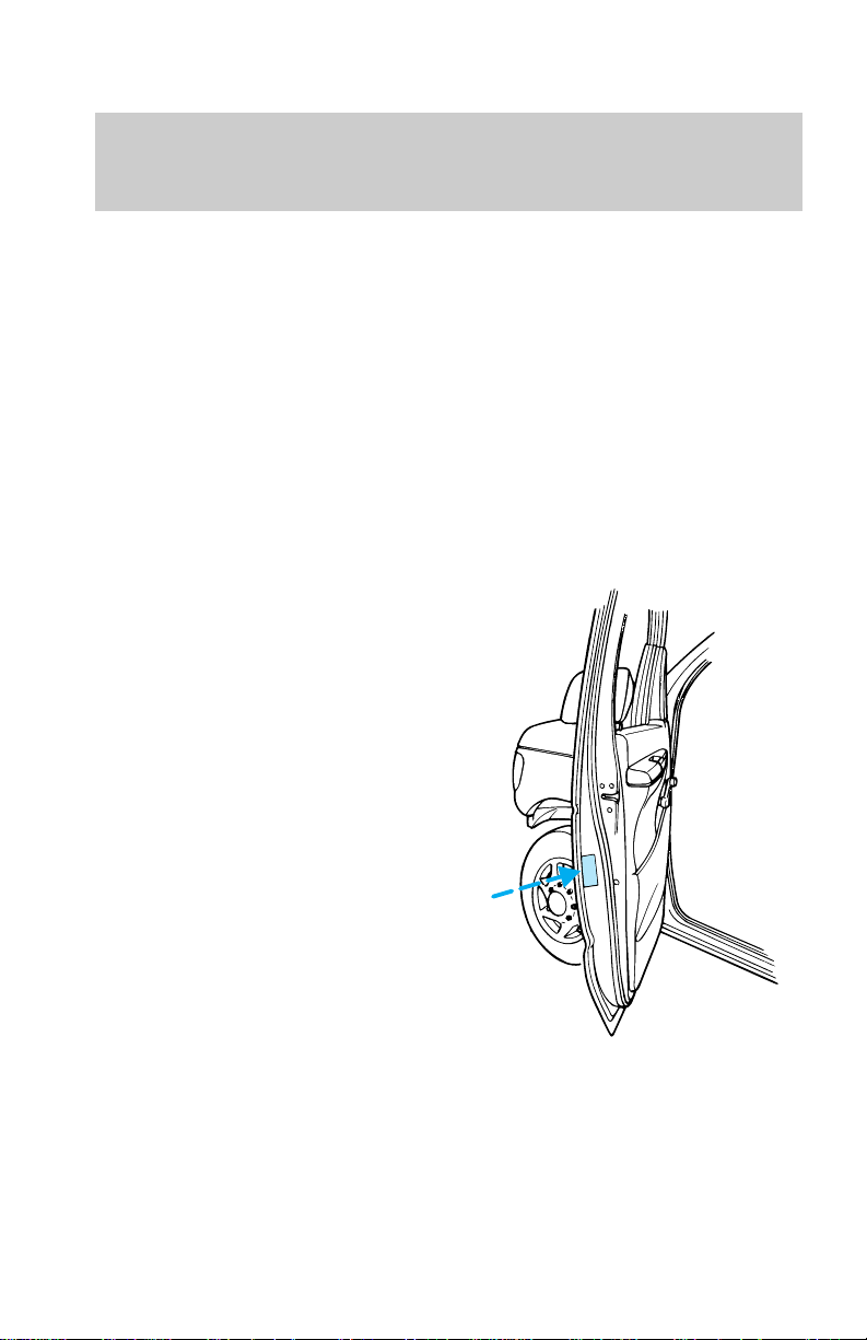
additional information, please
contact the Light Truck Body
Builders Advisory Service
1–800–635–5560.
Use of your Ford light truck as an
ambulance, without the Ford
Ambulance Preparation Package
voids the Ford New Vehicle
Limited Warranty and may void the
Emissions Warranties. In addition,
ambulance usage without the
preparation package could cause
high underbody temperatures,
overpressurized fuel and a risk of
spraying fuel which could lead to
fires.
If your vehicle is equipped with
the Ford ambulance preparation
package, it will be indicated on the
Safety Certification Compliance
label. The label is located on the
driver’s side door pillar or on the
rear edge of the driver’s door. You
can determine whether the
ambulance manufacturer followed
Ford’s recommendations by
directly contacting that
manufacturer. Ford Ambulance
preparation package is only
available on certain 7.3L Diesel
Econoline vehicles.
Introduction
Diesel-powered vehicles
Read the 7.3L Diesel Engine
Owner’s Guide Supplement for
information regarding correct
operation and maintenance of your
3
Page 4

Introduction
diesel-powered light truck.
BREAKING-IN YOUR VEHICLE
There are no particular breaking-in
rules for your vehicle. Simply avoid
driving too briskly during the first
1,600 km (1,000 miles) of driving.
Vary speeds frequently. This is
necessary to give the moving parts
a chance to break in.
If possible, you should avoid full
use of the brakes for the first
1,600 km (1,000 miles).
From 1,600 km (1,000 miles)
onwards you can gradually
increase the performance of your
vehicle up to the permitted
maximum speeds.
INFORMATION ABOUT THIS
GUIDE
The information found in this
guide was in effect at the time of
printing. Ford may change the
contents without notice and
without incurring obligation.
4
Page 5

Instrumentation
5
Page 6
Instrumentation
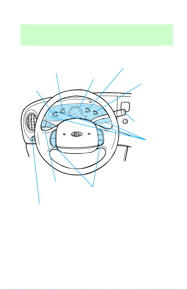
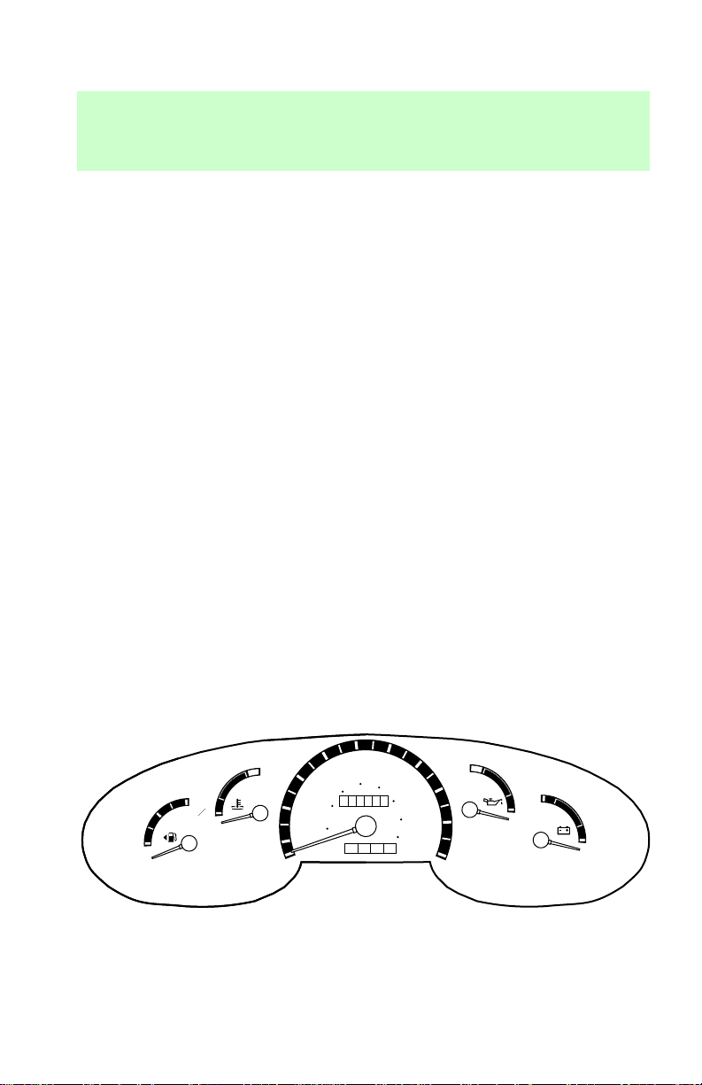
Engine coolant
temperature gauge
(pg. 12)
Fuel Gauge
(pg. 12)
Speedometer
(pg. 12)
Engine oil
pressure gauge
(pg. 13)
Battery
voltage
gauge
(pg. 13)
ON
OFF
Wiper/washer
control
(pg. 27)
Headlamp switch
and dimmer
(pg. 15)
RES
SET
ACCEL
COAST
Speed controls
(pg. 28)
OVERDRIVE
Transmission
control switch
(pg. 24)
Warning
lights
(pg. 8)
6
Page 7
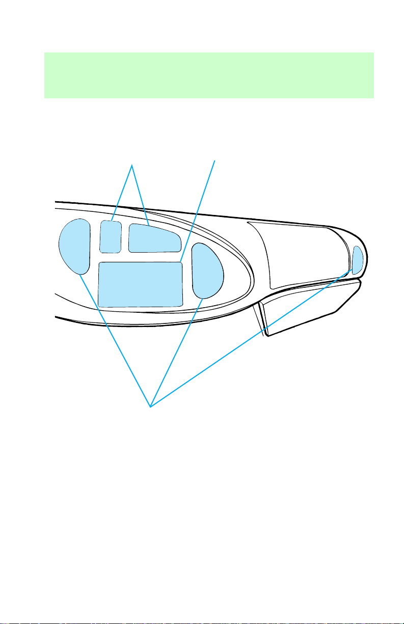
Climate controls
(pg. 17)
Instrumentation
Refer to
Audio Guide
(pg. 17)
Vents (pg. 18)
7
Page 8
Instrumentation
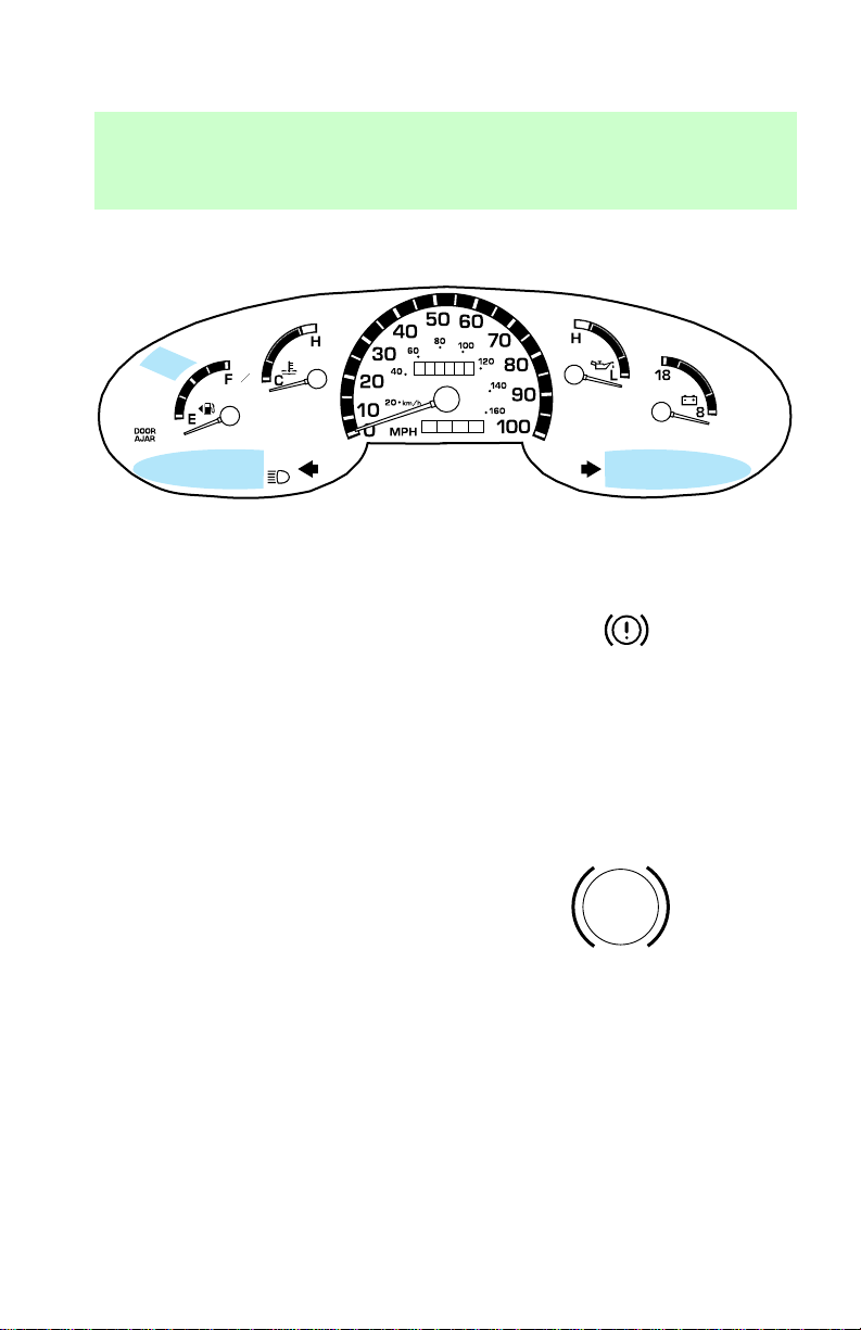
INSTRUMENT CLUSTER
LIGHTS
L
A
M
R
O
N
BRAKE
000000
0000
N
O
R
M
A
L
N
O
R
M
A
L
Brake system warning
This light illuminates when you
turn the ignition key to START to
verify that the indicator bulb is
working. If the light stays on or
comes on after you have released
the parking brake fully, have the
hydraulic brake system serviced.
This light also will illuminate if
vacuum pressure is low on diesel
engine vehicles.
Anti-lock brake system (ABS)
Momentarily illuminates when the
ignition is turned on and the
engine is off. If the light stays on
or continues to flash, the ABS
needs to be serviced.
Service engine soon
This light illuminates when the
engine’s Emission Control System
requires service. It will also
illuminate when the ignition key is
BRAKE
ABS
SERVICE
ENGINE SOON
8
Page 9
in the ON position and the engine
is off.
Transmission control indicator
light (TCIL)
The Transmission Control Indicator
Light (TCIL), which is located on
the gearshift lever, may flash
steadily if a malfunction is
detected. If the TCIL is flashing,
contact your Ford dealer as soon
as possible. If this condition
persists, damage to the
transmission could occur.
The word “OFF” located on the
end of the gearshift lever is the
transmission control indicator light
(TCIL).
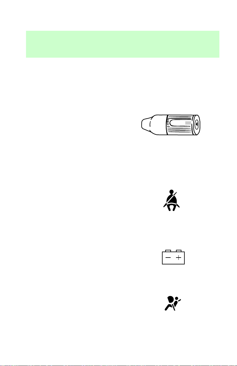
Safety belt
Illuminates when the ignition is
switched on to remind you to
fasten your safety belts. For more
information, refer to Using the
safety restraints properly in the
Seating and safety restraints
chapter.
Instrumentation
OVERDRIVE OFF
Charging system
Briefly illuminates when the
ignition is turned on and the
engine is off. The light also
illuminates when the battery is not
charging properly, requiring
electrical system service.
Air bag readiness
Briefly illuminates when the
ignition is turned on. If the light
fails to illuminate, continues to
9
Page 10

Instrumentation
flash or remains on, have the
system serviced immediately.
Turn signal
Illuminates when the left or right
turn signal or the hazard lights are
turned on.
High beams
Illuminates when the headlamp
high beams are on.
Door ajar (if equipped)
Illuminates when the ignition
switch is in the ON or START
position and any door is open.
Oil pressure/Engine coolant
This light will come on when the
key is in the ON position and the:
• engine coolant temperature is
very high
• engine oil pressure is low
The light serves as a notice that a
system needs your attention and to
check the engine coolant
temperature gauge and the engine
oil pressure gauge.
Refer to engine coolant
temperature gauge and engine oil
pressure gauge in this section for
more information.
DOOR
AJAR
10
Page 11
WARNING CHIMES
Safety belt warning chime
For information on the safety belt
warning chime, refer to the
Seating and safety restraints
chapter.
Supplemental restraint system
(SRS) warning chime
For information on the SRS
warning chime, refer to the
Seating and safety restraints
chapter.
Key-in-ignition warning
chime/buzzer
Sounds when the key is left in the
ignition and the driver’s door is
opened.
Headlamps on warning chime (if
equipped)
Sounds when the headlamps are
on, the ignition is off and the
driver’s door is opened.
Instrumentation
GAUGES
50
60
20
10
0
30
40
40
20 km/h
MPH
60
80
100
000000
0000
70
120
80
140
90
160
100
L
A
M
H
R
O
N
F
C
E
N
O
R
M
H
A
L
L
N
O
R
M
18
A
L
8
11
Page 12
Instrumentation
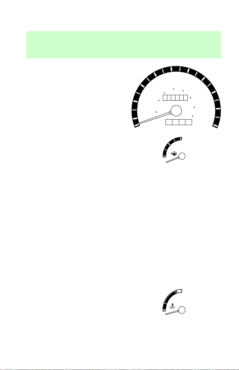
Speedometer
Indicates the current vehicle
speed.
20
10
0
30
20 km/h
50
40
60
000000
40
0000
MPH
80
60
100
120
70
80
140
90
160
100
Fuel gauge
The fuel gauge displays
approximately how much fuel is in
the fuel tank, when the ignition
switch is ON.
The fuel gauge indicator may vary
slightly when the vehicle is in
motion.
The vehicle should be refueled
with the ignition key in the OFF
position. If the vehicle is refueled
with the key in the ON position,
the key must be turned to the OFF
position and then the vehicle
started to get an accurate fuel
gauge reading. If the vehicle is
fueled with the key in the ON
position and the above mentioned
is not performed, it will take
approximately 25 minutes for the
gauge to go from “E” to “F.”
Engine coolant temperature
gauge
Indicates the temperature of the
engine coolant. At normal
operating temperature, the needle
remains within the normal area. If
it enters the red section, the
F
E
H
C
12
Page 13
engine is overheating. Switch off
the ignition and let it cool. Refer to
Checking and adding engine
coolant in the Maintenance and
care chapter.
Instrumentation
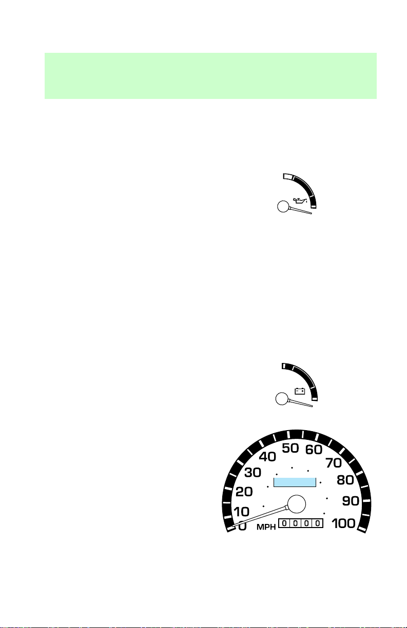
Engine oil pressure gauge
This shows the engine oil pressure
in the system. Sufficient pressure
exists as long as the needle
remains in the normal range.
If the gauge indicates constantly
low pressure at normal engine
speed, refer to Checking and
adding engine oil in the
Maintenance and care chapter. If
the gauge indicates a low pressure
and the engine oil level is correct,
switch off the engine immediately
and have your vehicle checked at
your dealership or by a qualified
technician.
Charging system gauge
If the pointer moves and stays
outside of the normal range, have
the vehicle’s electrical system
checked as soon as safely possible.
Odometer
Registers the total kilometers
(mileage) of the vehicle.
60
40
20 km/h
18
H
L
8
80
100
120
140
160
13
Page 14
Instrumentation
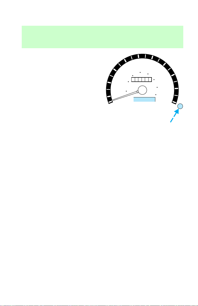
Trip odometer
Can register the kilometers
(mileage) of individual journeys.
To reset, depress the control.
20
10
0
30
20 km/h
40
60
000000
40
MPH
50
60
80
0000
100
70
120
140
160
80
90
100
14
Page 15
INSTRUMENT PANEL
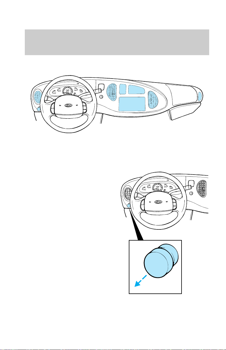
CONTROLS
Headlamp control
1. Pull the headlamp control
toward you to the first position.
Parking lamps, tail lamps, license
plate lamps and marker lamps are
now on.
Controls and features
15
Page 16
Controls and features
2. Pull the headlamp control
toward you to the outer position.
Headlamps are now on in addition
to above.
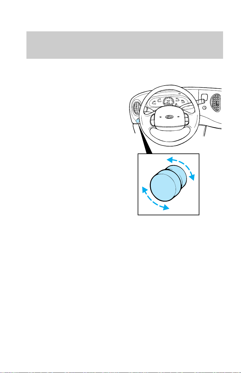
3. Rotate the control when it is in
the on position to brighten or dim
the instrument panel lamps. Rotate
fully counterclockwise to operate
courtesy and cargo lamps.
Daytime running light (DRL)
system (if equipped)
The DRL system turns on the high
beam headlamps, with a reduced
light output, when:
• the vehicle is running (ignition
switch is in the ON position)
• the vehicle has a fully released
parking brake
16
Page 17
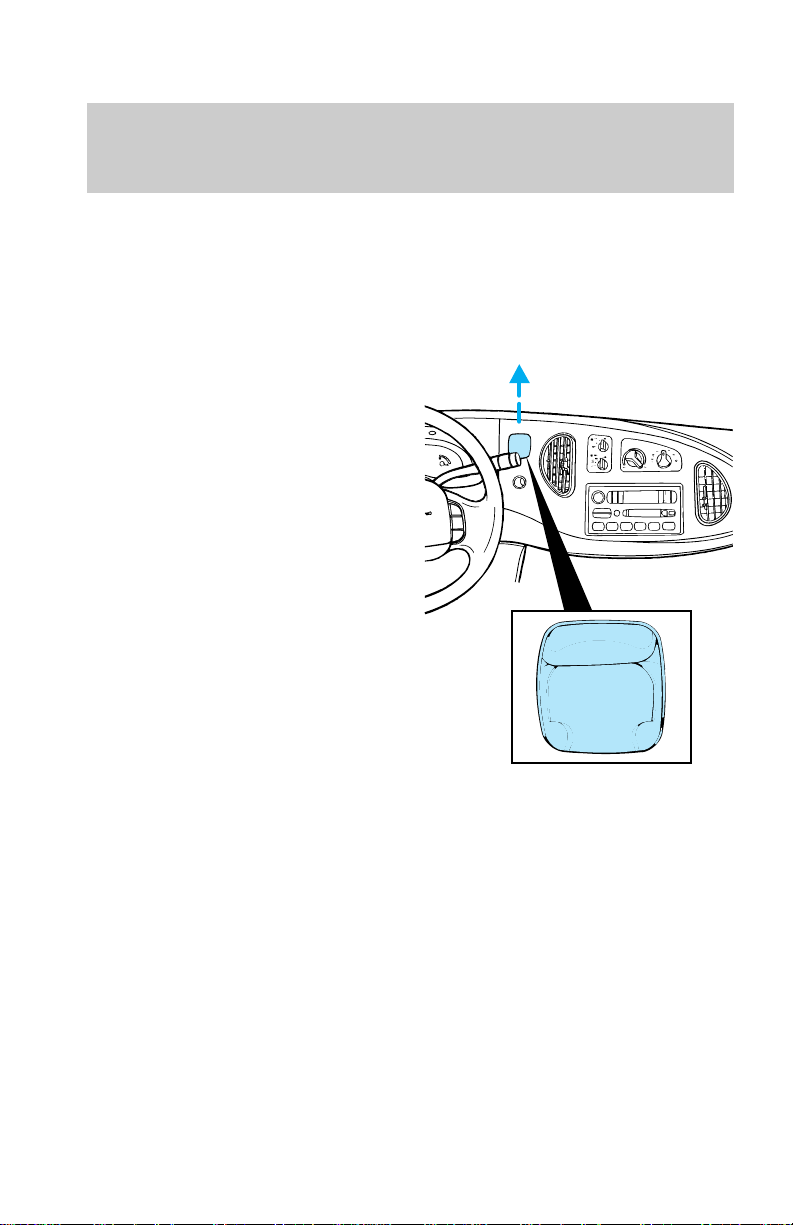
• the headlamp system is in the
OFF or park lamp position
Audio System
For information on the audio
system, refer to the Audio Guide.
Power point electrical outlet
The power point is a power source
for the operation of electrical
accessories.
Do not use the cigarette lighter in
place of the power point.
Controls and features
CLIMATE CONTROLS
Your vehicle has one of the
following climate control systems:
• Manual heating system
• Manual heating and air
conditioning system
In addition your vehicle may also
be equipped with a auxiliary heater
and air conditioning system.
In some modes, the systems
function similarly; in modes where
the systems do not function
17
Page 18
Controls and features
similarly, the different functions
are noted.
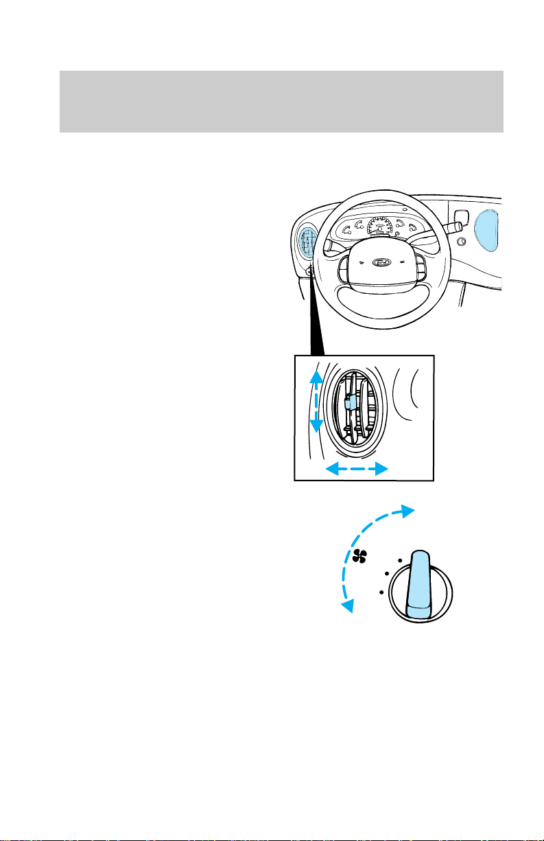
Vents
Airflow from the vents may be
manually adjusted by moving the
horizontal control or vertically
adjusting the vent according to
your airflow preference.
Fan speed
Turn the fan speed control to the
desired speed.
FRONT
HI
18
LO
Page 19
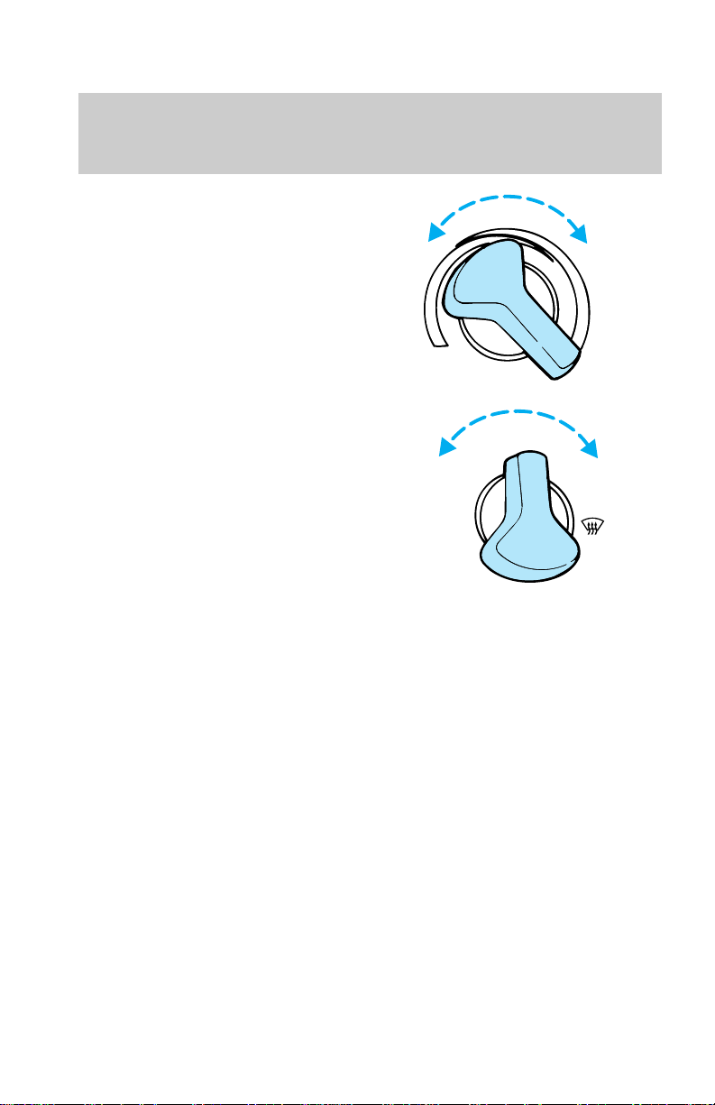
Temperature
Turn the temperature control to
the desired mix of warm and cool
air (left for cooler and right for
warmer).
Controls and features
Controlling airflow
Turn the mode control to the
desired airflow position.
Using MAX A/C mode (if
equipped)
The MAX A/C mode recirculates
the air and directs it to flow
through the instrument panel
vents. The MAX A/C mode can be
used for air conditioning or
heating. This mode is noisier, but
more economical than A/C mode.
The MAX A/C mode only functions
if the outside temperature is above
10°C (50°F).
Select the OFF position for all
climate control functions to cease.
The outside inlet door will close
and the fan is shut off.
COOLCOOL
NORM
MAX
A C
A C
/
VENT
/
OFF
ARM
FLR
MIX
19
Page 20
Controls and features
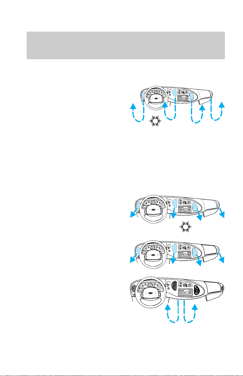
Drive with the climate control
system on (either in heating or
A/C mode) to reduce humidity in
your vehicle.
Select MAX A/C for airflow
through these vents:
Using NORM A/C mode (if
equipped)
The NORM A/C mode directs
outside conditioned air to flow
through the instrument panel
vents. The NORM A/C mode can
be used for heating, ventilating or
air conditioning. The NORM A/C
mode only functions if the outside
temperature is above 10°C (50°F).
Select NORM A/C for air to flow
through these vents:
Using the vent mode
Select the VENT mode for air to
flow through these vents:
Using the floor mode
Select the FLOOR mode for air to
flow through these vents:
20
Page 21
Using the mix mode
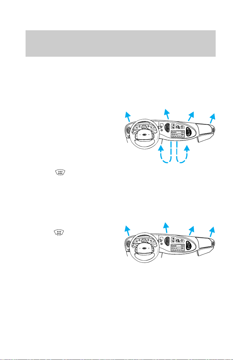
The MIX mode directs outside air
to flow through the floor vents and
windshield defroster vents. The air
conditioning will function to
dehumidify the windows provided
the outside temperature is above
10°C (50°F).
Select the MIX mode for air to flow
through these vents:
Using the mode
In addition to defogging and
demisting, in defrost mode your
vehicle has the capability to demist
the front side windows. The air
conditioning will function to
dehumidify the windows provided
the outside temperature is above
10°C (50°F).
Select the
through these vents:
mode for air to flow
Controls and features
AUXILIARY HEATER AND AIR
CONDITIONER (IF EQUIPPED)
If your vehicle is equipped with a
factory installed auxiliary unit, the
front control panel will include
21
Page 22
Controls and features
separate controls for the front and
rear fans.
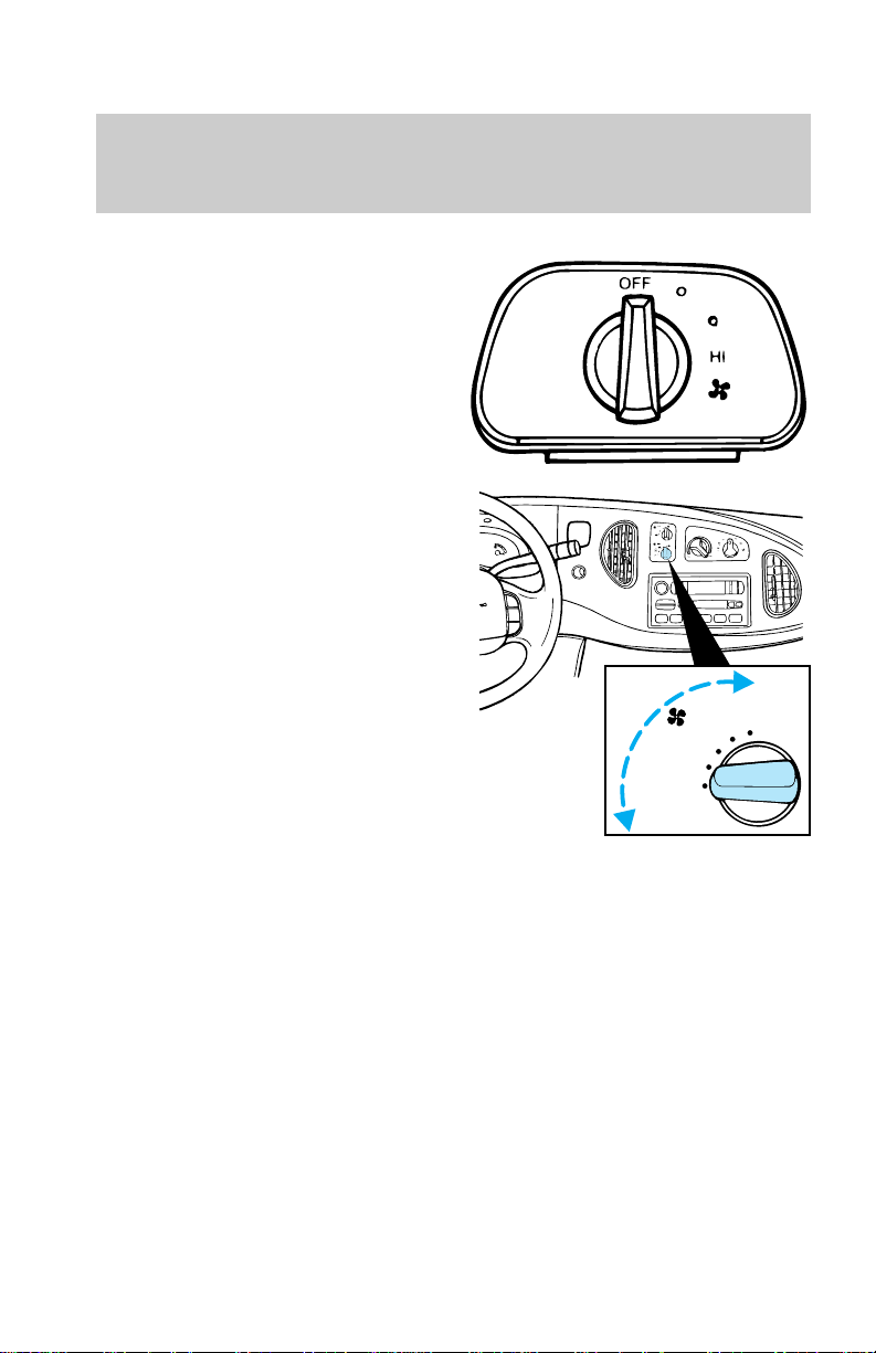
In addition an auxiliary unit fan
control is located in the headliner
at a location between the front and
rear seats.
• To control the auxiliary fan with
this control, the rear fan switch
on the front control unit must
be in the rear control position.
• The auxiliary unit does not
provide for mixing of hot and
cold air. Adjustment of
temperature in the rear may be
accomplished by increasing or
decreasing the rear fan speed.
REAR
REAR
CTRL
OFF
HI
LO
22
Page 23
STEERING COLUMN
CONTROLS
Controls and features
ON
OFF
RES
SET
ACCEL
COAST
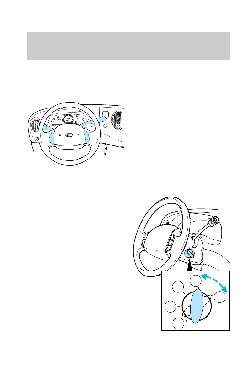
Ignition
ACCESSORY (1) allows operation
of some accessories without
starting the engine.
LOCK (2) locks the steering wheel
and allows the key to be removed
from the ignition. LOCK also locks
the gearshift.
OFF (3) shuts off the engine and
all accessories without locking the
steering wheel or gearshift.
ON (4) allows testing of the
vehicle’s warning and indicator
lights.
START (5) cranks the engine. The
key returns to the ON position
after it is released.
For more information on the
vehicle ignition and starting the
vehicle, refer to Preparing to start
x
x
xxx
xxx
xxx
xxx
4
3
5
2
1
23
Page 24
Controls and features
the vehicle in the Starting
chapter.
Gearshift
For information on the gearshift,
refer to Automatic Transmission
Operation section of the Driving
chapter.
P RN 21
D
Using overdrive
D
(overdrive) is the normal drive
position for the best fuel economy.
The overdrive function allows
automatic upshift and downshift
operation in all gears.
24
P RN 21
D
Page 25
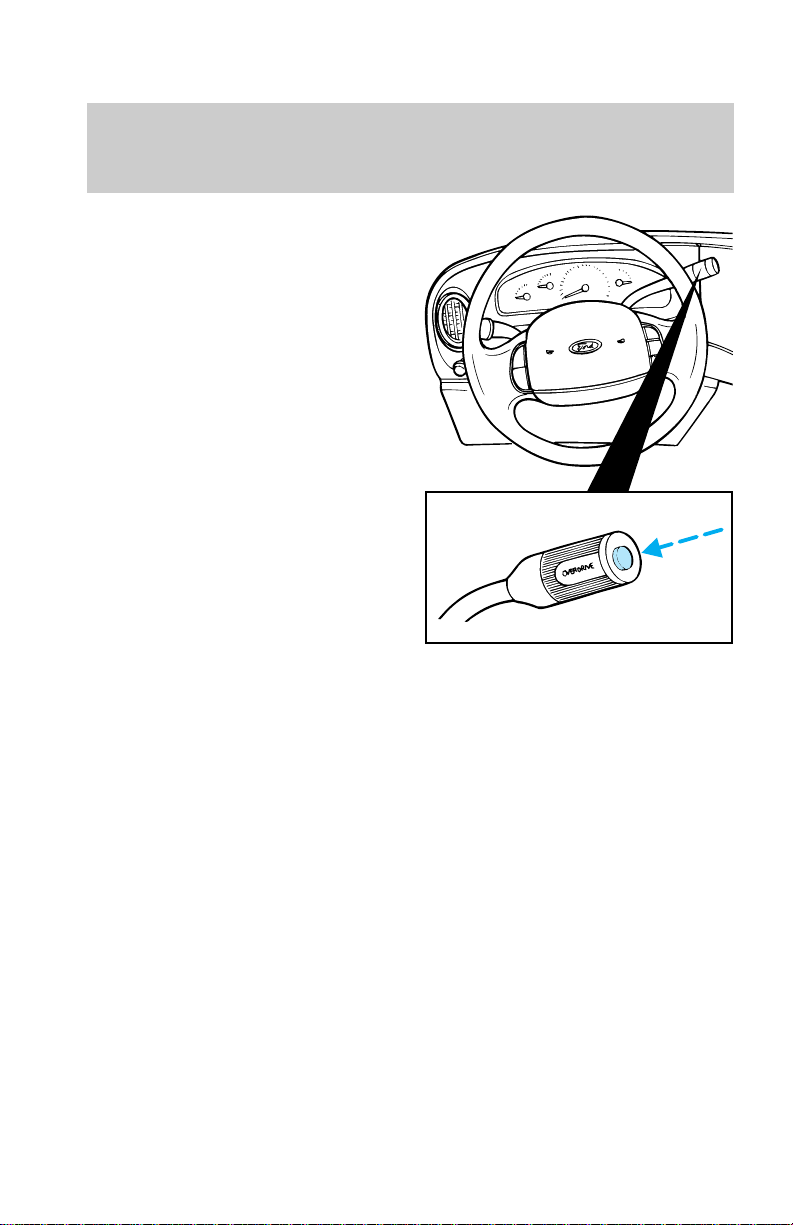
Deactivating overdrive
Press the transmission control
switch (TCS) on the end of the
gearshift lever. The Transmission
Control Indicator Light (TCIL)
(the word “OFF” on the gearshift
lever) will illuminate. The
transmission will only operate in
gears one through three.
Deactivate overdrive when:
• driving with a heavy load
• driving in hilly terrain
• additional engine braking is
desired
Activating overdrive
To return to normal overdrive
operation, press the TCS again.
The light illuminating the word
“OFF” will turn off.
When restarting your vehicle, the
transmission will automatically
return to the normal overdrive
operation mode.
Controls and features
25
Page 26
Controls and features
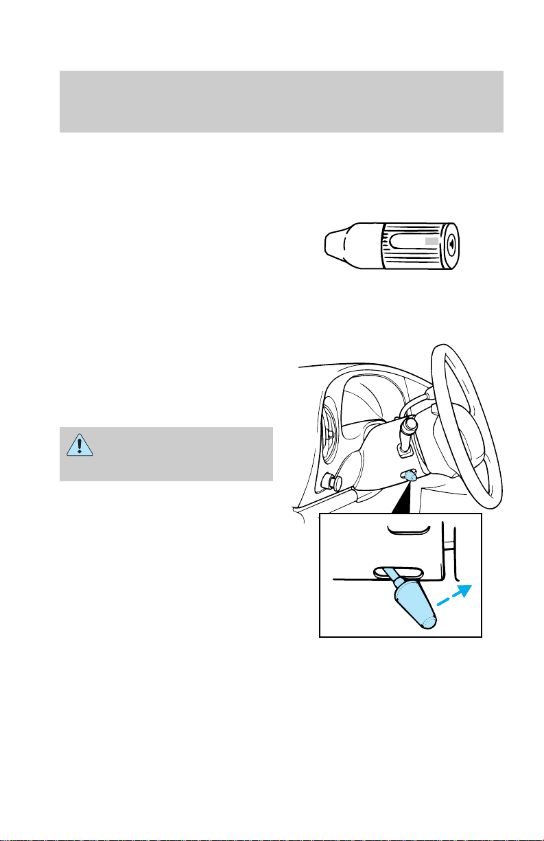
Transmission control indicator
light (TCIL)
The TCIL (the word “OFF”)
located on the gearshift lever
indicates the status of the
transmission.
The TCIL may flash steady if a
malfunction is detected. If this
occurs have your transmission
serviced by your Ford dealer as
soon as possible or damage may
occur.
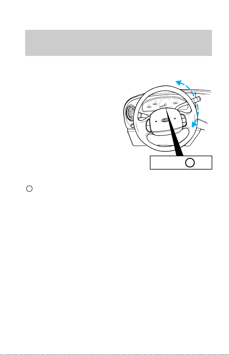
Tilt steering
Pull the control to adjust the
steering column angle. Push the
control back up to lock the
steering wheel into position.
Never adjust the steering
wheel when the vehicle is
moving.
OVERDRIVE OFF
26
Page 27
Hazard flasher control
For more information on the
hazard flasher control, refer to the
Roadside emergencies chapter.
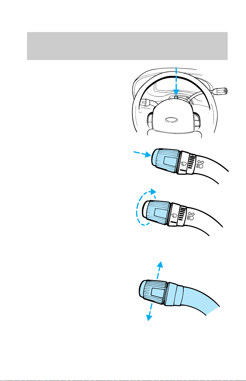
Windshield wipers and washer
• Push the end to activate the
washer.
• Push end once for a single wipe.
• Push and hold for a constant
cycle.
Controls and features
O
O
• Turn the dial to adjust
intermittent wiper speed.
Flash— to— pass
Pull toward you and release for
“flash-to-pass” operation.
O
27
Page 28
Controls and features
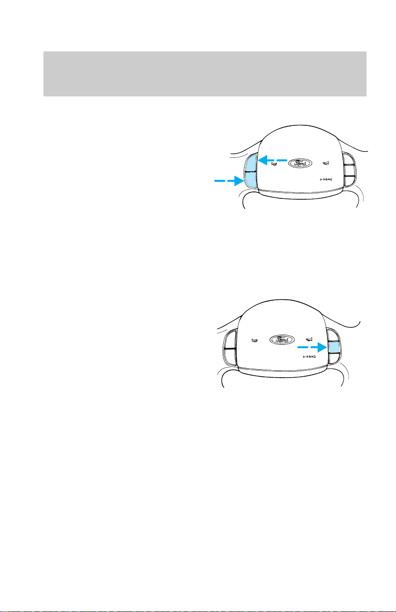
Speed control (if equipped)
To turn speed control on
• Press ON
To turn speed control off
• Press OFF or
• Turn off the vehicle ignition.
Once speed control is switched off,
the previously programmed set
speed will be erased.
To set a speed
Press SET ACCEL. For speed
control to operate, the speed
control must be ON and the
vehicle speed must be greater than
48 km/h (30 mph).
ON
OFF
ON
OFF
RES
SET
ACCEL
COAST
RES
SET
ACCEL
COAST
If you drive up or down a steep
hill, your vehicle speed may vary
momentarily slower or faster than
the set speed. This is normal.
Speed control cannot reduce the
vehicle speed if it increases above
the set speed on a downhill. If
your vehicle speed is faster than
the set speed while driving on a
downhill in Overdrive, you may
want to shift to the next lower
gear to reduce your vehicle speed.
28
Page 29
If your vehicle slows downs more
than 16 km/h (10 mph) below your
set speed on an uphill, your speed
control will disengage. This is
normal. Pressing RES will
re-engage it.
Do not use the speed
control in heavy traffic or
on roads that are winding,
slippery, or unpaved.
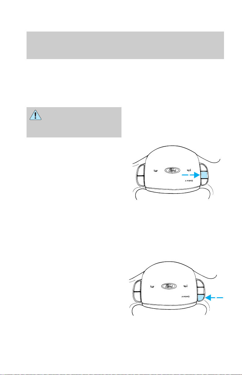
To set a higher speed
• Press and hold SET ACCEL.
Release the switch when the
desired vehicle speed is
reached, or
• Press and release SET ACCEL.
Each press will increase the set
speed by 1.6 km/h (1 mph) or
• Accelerate with your accelerator
pedal, then press SET ACCEL.
You may accelerate with the
accelerator pedal at any time
during speed control usage.
Releasing the accelerator pedal will
return your vehicle speed to the
previously programmed set speed.
To set a lower set speed
• Press and hold COAST. Release
the switch when the desired
vehicle speed is reached, or
• Press and release COAST. Each
press will decrease the set
speed by 1.6 km/h (1 mph) or
• Depress the brake pedal. When
the desired vehicle speed is
reached press SET ACCEL.
Controls and features
ON
OFF
ON
OFF
RES
SET
ACCEL
COAST
RES
SET
ACCEL
COAST
29
Page 30
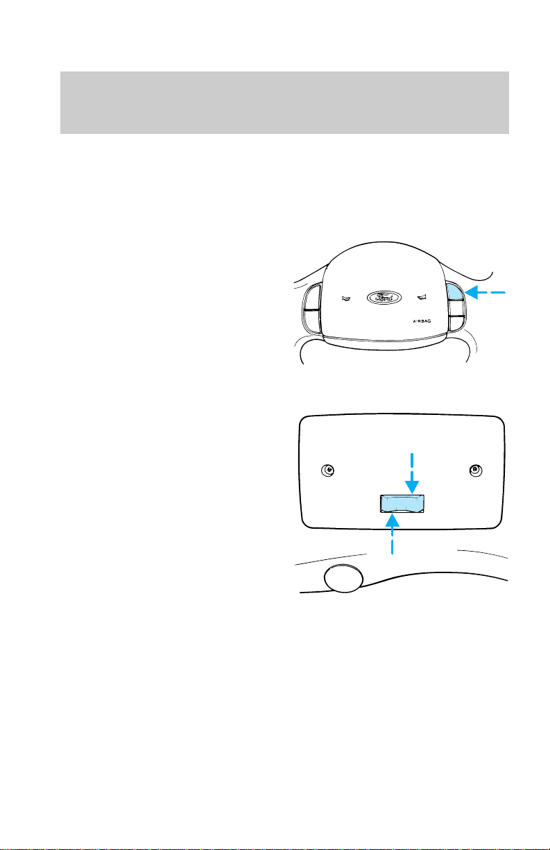
Controls and features
To disengage speed control
• Depress the brake pedal.
Disengaging the speed control will
not erase the previously
programmed set speed.
To return to a set speed
• Press RES. For RES to operate,
the vehicle speed must be faster
than 48 km/h (30 mph).
OVERHEAD CONTROLS
Cargo and dome lamps
Rear cargo lamps equipped with an
ON/OFF/DOOR control will light
when:
• the doors are closed and the
switch is in the ON position
• either front door is open and
the switch is in the DOOR
position
• the headlamp control is rotated
fully counterclockwise
When the cargo lamp switch is in
the OFF position, it will not
illuminate when you open the
doors or turn the headlamp
control.
ON
OFF
DOOR
OFF
RES
SET
ACCEL
COAST
ON
30
Page 31

Courtesy/reading lamps
The courtesy/reading lamps will
illuminate when:
• the lens is in the flat position
and any door is open
• the lens is in the flat position
and the headlamp control is
rotated fully counterclockwise
• the lens is in the rotated
position.
DOOR MOUNTED CONTROLS
Power outside mirrors (if
equipped)
To adjust the outside mirrors:
1. Select the mirror you want to
adjust:
Driver side mirror
Passenger side mirror
2. Move the mirror control in the
desired direction.
3. Lock the mirror by moving the
control to the center
position.
Controls and features
31
Page 32
Controls and features
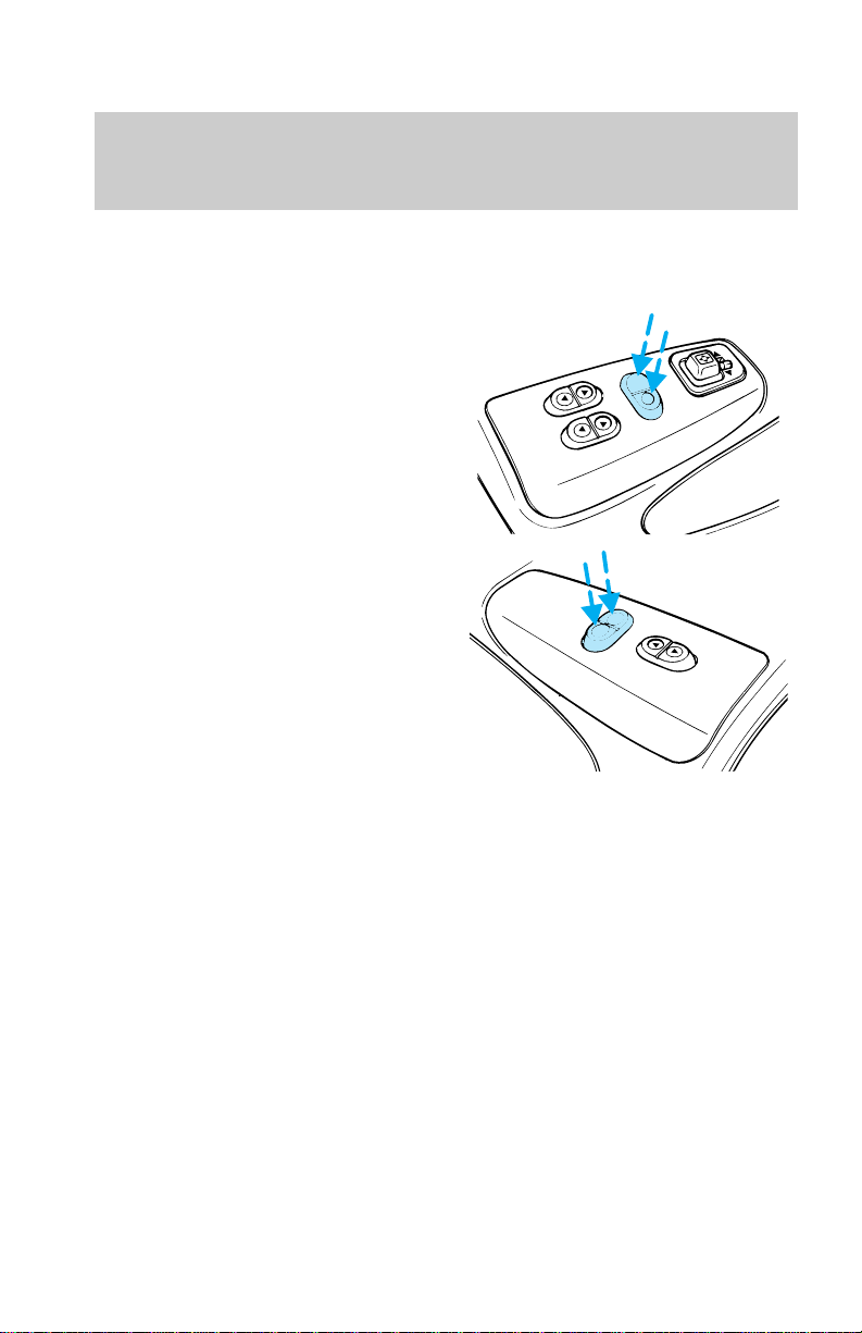
Power door locks (if equipped)
Push to lock or unlock the doors.
L All doors locked
U All doors unlocked
• Driver side
• Passenger side
U
L
U
L
32
Page 33
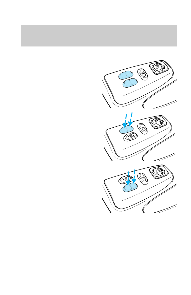
Power Windows (if equipped)
Driver side controls
Press the appropriate window
switch to operate the power
windows.
• Driver window
• Front passenger window
Controls and features
U
L
U
L
U
L
33
Page 34
Controls and features
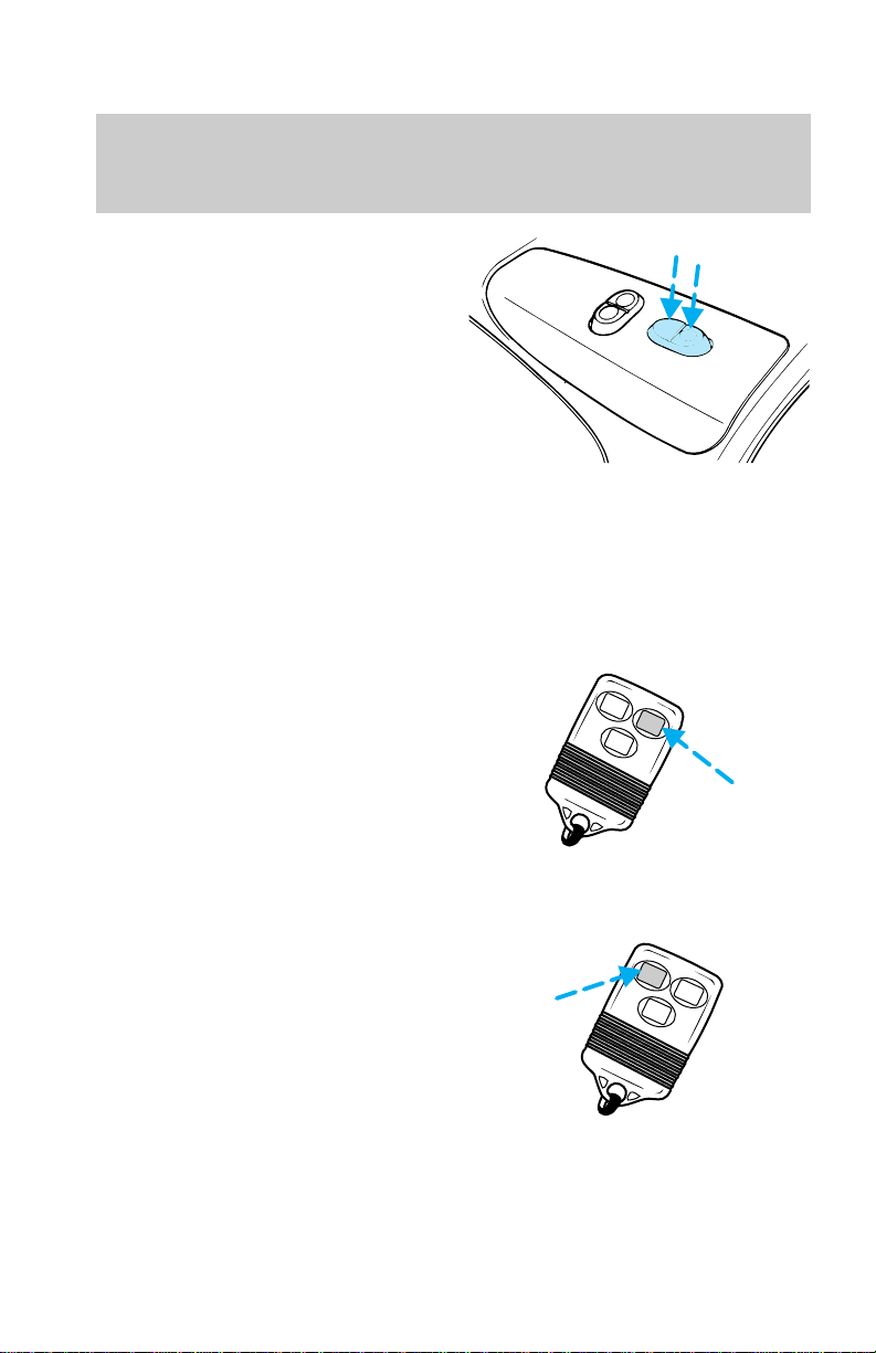
Passenger side controls
Press the window switch to
operate the power window.
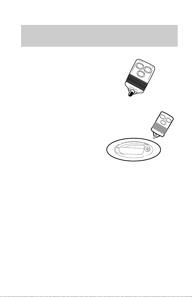
REMOTE ENTRY SYSTEM (IF
EQUIPPED)
The remote entry system allows
you to lock or unlock all vehicle
doors without a key.
Unlocking the doors
Press UNLOCK to unlock the
driver door. The interior lamps will
illuminate.
Press UNLOCK a second time
within five seconds to unlock all
doors.
U
L
LOCK
UN
LOCK
PANIC
Locking the doors
Press LOCK to lock all doors.
To confirm all doors are closed and
locked, press the LOCK button a
second time within five seconds.
The doors will lock again, the horn
will chirp and the lamps will flash.
34
LOCK
UN
LOCK
PANIC
Page 35

Sounding a panic alarm
Press the PANIC control to
activate the alarm.
To deactivate the alarm, press the
PANIC control again or turn the
ignition to the ACC or ON position.
This device complies with part 15
of the FCC rules. Operation is
subject to the following two
conditions: (1) This device may
not cause harmful interference,
and (2) This device must accept
any interference received,
including interference that may
cause undesired operation.
Replacing the batteries
The transmitter is powered by two
coin type three-volt lithium
batteries. A decrease in operating
range can be caused by:
• battery failure
• weather conditions
• structures around the vehicle
To replace the batteries:
1. Twist a thin coin between the
two halves of the transmitter. DO
NOT TAKE THE FRONT PART OF
THE TRANSMITTER APART.
2. Place the positive (+) side of
new batteries down.
3. Snap the two halves back
together.
Controls and features
LOCK
UN
LOCK
PANIC
35
Page 36
Controls and features
Replacing lost transmitters
Take all your vehicle’s transmitters
to your dealer for reprogramming
if:
• a transmitter is lost or
• you want to purchase additional
transmitters (up to four may be
programmed).
LOCK
UN
LOCK
PANIC
Illuminated entry system
The interior lamps illuminate
when:
• either front door handle is lifted
or
• the remote entry system is used
to unlock the door or sound the
personal alarm.
The system automatically turns off
after 25 seconds or when the
ignition is turned to the START or
ACC position.
The inside lights will not turn off
if:
• they have been turned on with
the dimmer control or
• any door is open.
LOCK
UN
LOCK
PANIC
36
Page 37
Seating and safety restraints
SEATS
Front seats
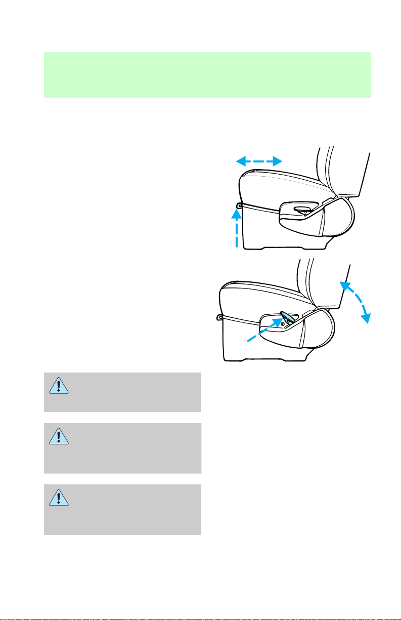
Adjusting manual seats
Lift the adjustment control to
move the seat forward or
backward.
Pull the control up to recline the
seat
Never adjust the driver’s
seat or seatback when the
vehicle is moving.
Do not pile cargo higher
than the seatbacks to
avoid injuring people in a
collision or sudden stop.
Always drive and ride with
your seatback upright and
the lap belt snug and low across
the hips.
37
Page 38
Seating and safety restraints
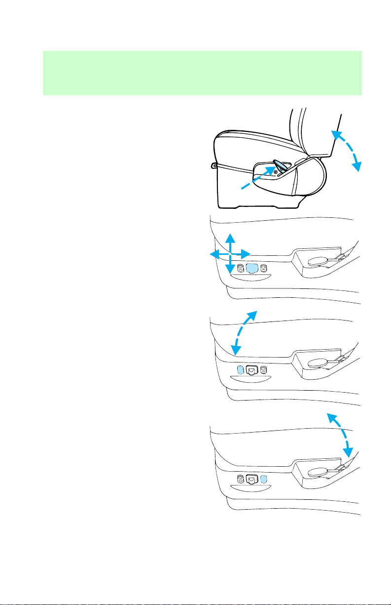
Adjusting power seats
Pull the control up to recline the
seat
Move the control in the direction
you want the seat to move.
• Forward to move seat forward
• Rearward to move seat rearward
• Up to raise the seat
• Down to lower the seat
Push the control to tilt the front of
the seat up or down.
Push the control to tilt the rear of
the seat up or down.
38
Page 39
Seating and safety restraints
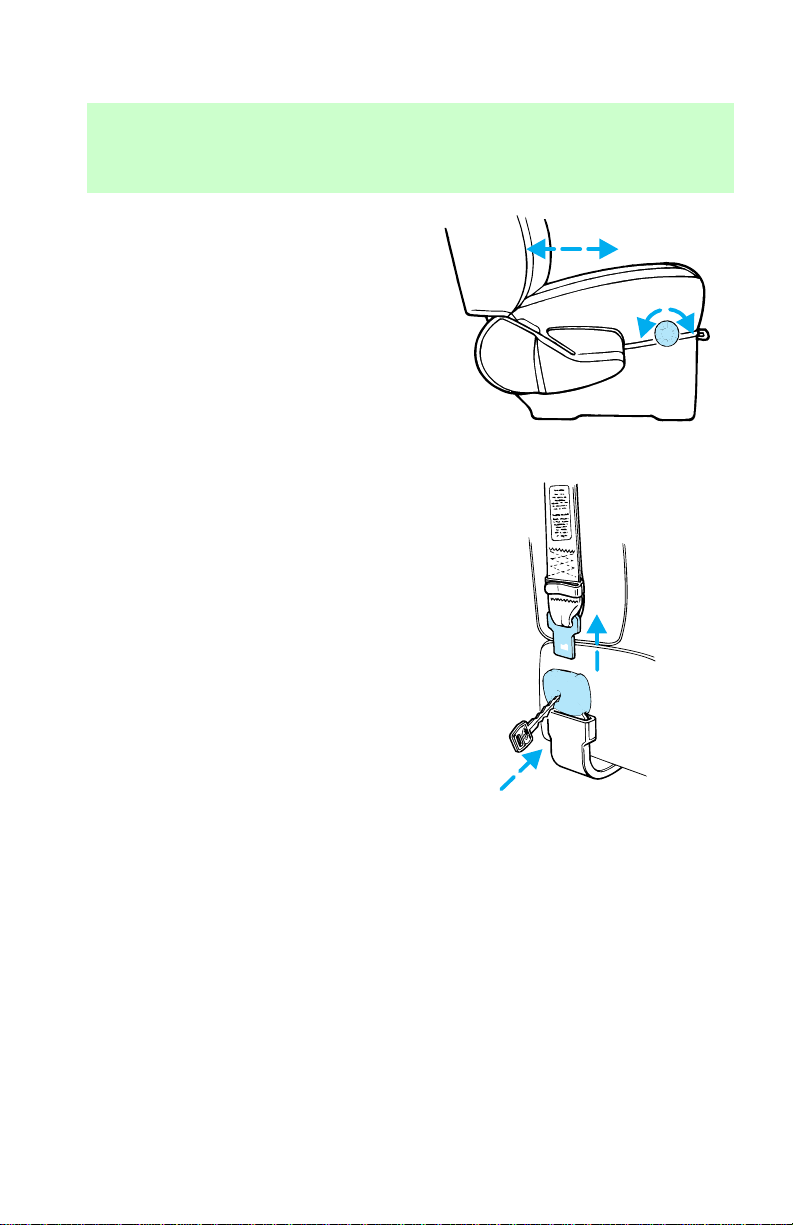
Lumbar support (if equipped)
Rotate the control on the seat to
increase or decrease the lumbar
support.
Rear bench seat
To remove the seats:
1. Disengage the lap/shoulder belt
from the seat by inserting a key or
small screwdriver into the slot in
39
Page 40
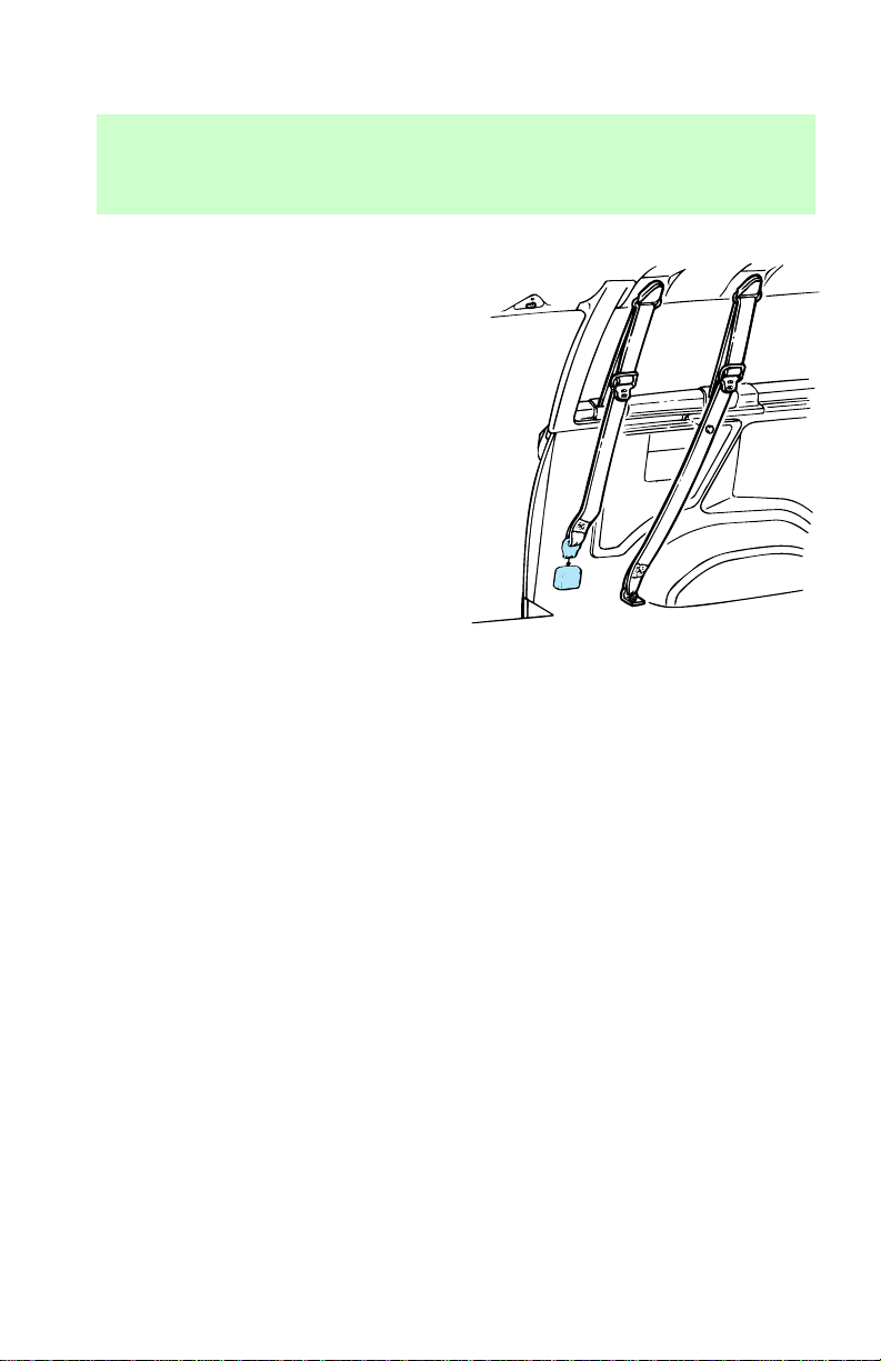
Seating and safety restraints
the detachable anchor and lifting
upward.
Stow the tongue end of the
detachable anchor.
2. Lift and rotate the LH/RH seat
latch handles rearward.
3. Lift the LH/RH latch rod hook
ends out of the locking holes in
the front strikers.
4. Move the seat rearward and lift
the seats rear hooks away from the
rear strikers prior to lifting the
front hooks out from the front
strikers.
5. Remove the seat assembly.
To install the seat:
1. Position the seat in the vehicle.
2. Align front hooks to front
strikers, prior to lowering the rear
hooks and aligning them with the
rear strikers.
40
Page 41
Seating and safety restraints
3. Engage the LH/RH latch rod
hook ends in the front striker
locking holes.
4. Rotate the LH/RH latch handles
forward, and at the same time
slide the seat assembly forward to
engage the strikers. Continue
forward movement until the seat
reaches the end of its travel.
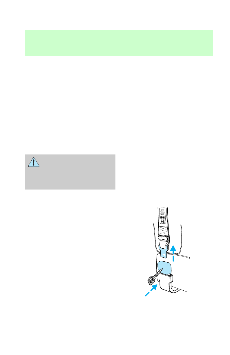
5. Make sure the safety belt is not
twisted, then insert the seat belt
tongue into detachable anchor
until you hear a “click” and feel
the latch engage.
Always latch the vehicle
seat to the floor, whether
the seat is occupied or empty. If
not latched, the seat may cause
injury during a sudden stop.
Quick release captains chair
To remove the seats:
1. Disengage the lap/shoulder belt
from the seat by inserting a key or
small screwdriver into the slot in
41
Page 42
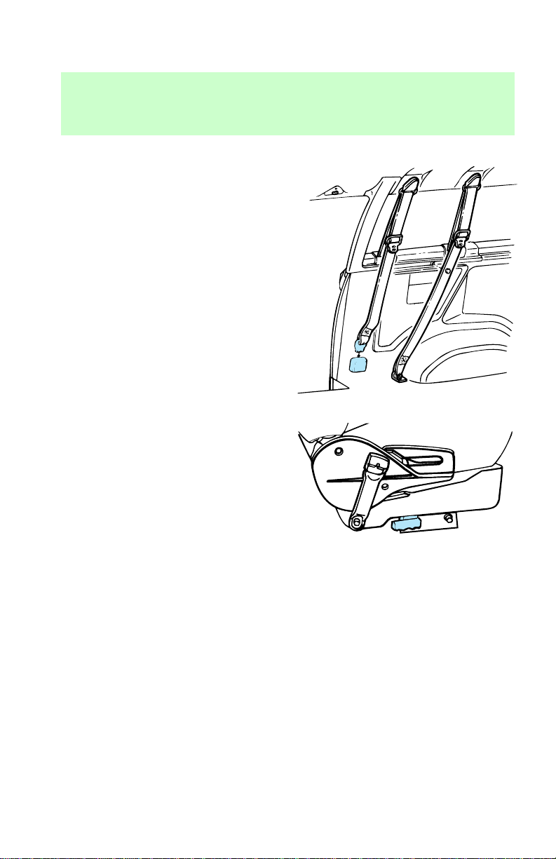
Seating and safety restraints
the detachable anchor and lifting
upward.
Stow the tongue end of the
detachable anchor.
2. Pull the seat latch handle, then
pull the seat toward the right side
of the vehicle to disengage four
pins from the floor mount.
3. Remove the seat.
42
Page 43
Seating and safety restraints
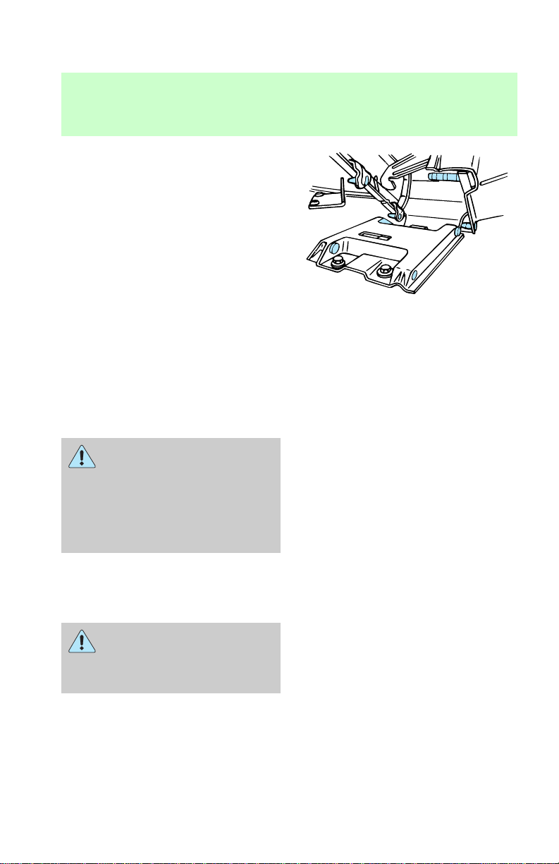
To install the seats:
1. Position the seat to the floor
mount.
2. Engage the four pins into the
floor mount hole and push the seat
toward the left side of the vehicle
to fully engage.
3. Pull the seat latch handle
downward to lock the seat in
position.
4. Make sure the safety belt is not
twisted, then insert the seat belt
tongue into detachable anchor
until you hear a “click” and feel
the latch engage.
Check to see that the seat
and seatback is latched
securely in position. Keep floor
area free of objects that would
prevent proper seat engagement.
Never attempt to adjust the seat
while the vehicle is in motion.
SAFETY RESTRAINTS
Safety restraints precautions
Always drive and ride with
your seatback upright and
the lap belt snug and low across
the hips.
43
Page 44

Seating and safety restraints
To prevent the risk of
injury, make sure children
sit where they can be properly
restrained.
Never let a passenger hold
a child on his or her lap
while the vehicle is moving. The
passenger cannot protect the
child from injury in a collision.
It is extremely dangerous
to ride in a cargo area,
inside or outside of a vehicle. In
a collision, people riding in these
areas are more likely to be
seriously injured or killed. Do not
allow people to ride in any area
of your vehicle that is not
equipped with seats and safety
belts. Be sure everyone in your
vehicle is in a seat and using a
safety belt properly.
Each seating position in
your vehicle has a specific
safety belt assembly which is
made up of one buckle and one
tongue that are designed to be
used as a pair. 1) Use the
shoulder belt on the outside
shoulder only. Never wear the
shoulder belt under the arm. 2)
Never swing it around your neck
over the inside shoulder. 3)
Never use a single belt for more
than one person.
44
Page 45
Seating and safety restraints
Safety belt buckle pretensioner
Your vehicle is equipped with
safety belt buckle pretensioners at
the driver and front passenger
seating positions.
The safety belt buckle pretensioner
is a device which removes excess
webbing from the safety belt
system. The safety belt buckle
pretensioner uses the same crash
sensor system as the air bag
supplemental restraint system
(SRS). When the safety belt buckle
pretensioner deploys, the buckle
moves downward, pulling excess
webbing from the lap and shoulder
safety belt.
Combination lap and shoulder
belts
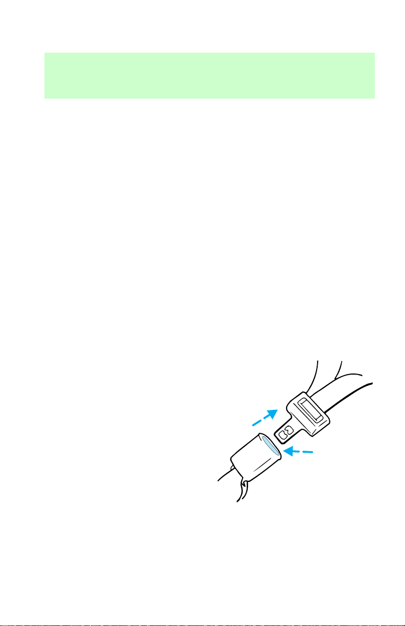
To fasten the safety belt, insert the
tongue into the slot in the buckle.
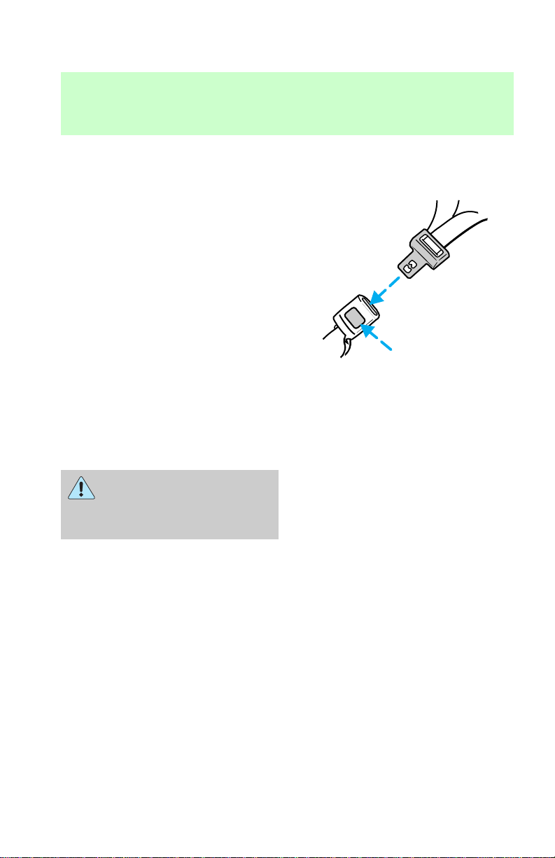
To disconnect the safety belt at:
• front seating positions, push the
red release button on the end of
45
Page 46
Seating and safety restraints
the buckle and remove the
tongue from the buckle.
• rear seating positions, push the
red release button on the side of
the buckle and remove the
tongue from the buckle.
The lap belts should fit
snugly and as low as
possible around the hips, not
around the waist.
PRESS
The outboard safety restraints in
the vehicle are combination lap
and shoulder belts. The front
passenger and rear outboard
seating positions safety belts have
two types of locking modes.
46
Page 47
Seating and safety restraints
Vehicle sensitive (emergency)
locking mode
In this mode, the shoulder belt will
allow freedom of movement,
locking tight only on hard braking,
hard cornering or impacts of
approximately 8 km/h (5 mph) or
more. The front seat belts can also
be made to lock by jerking on the
belt.
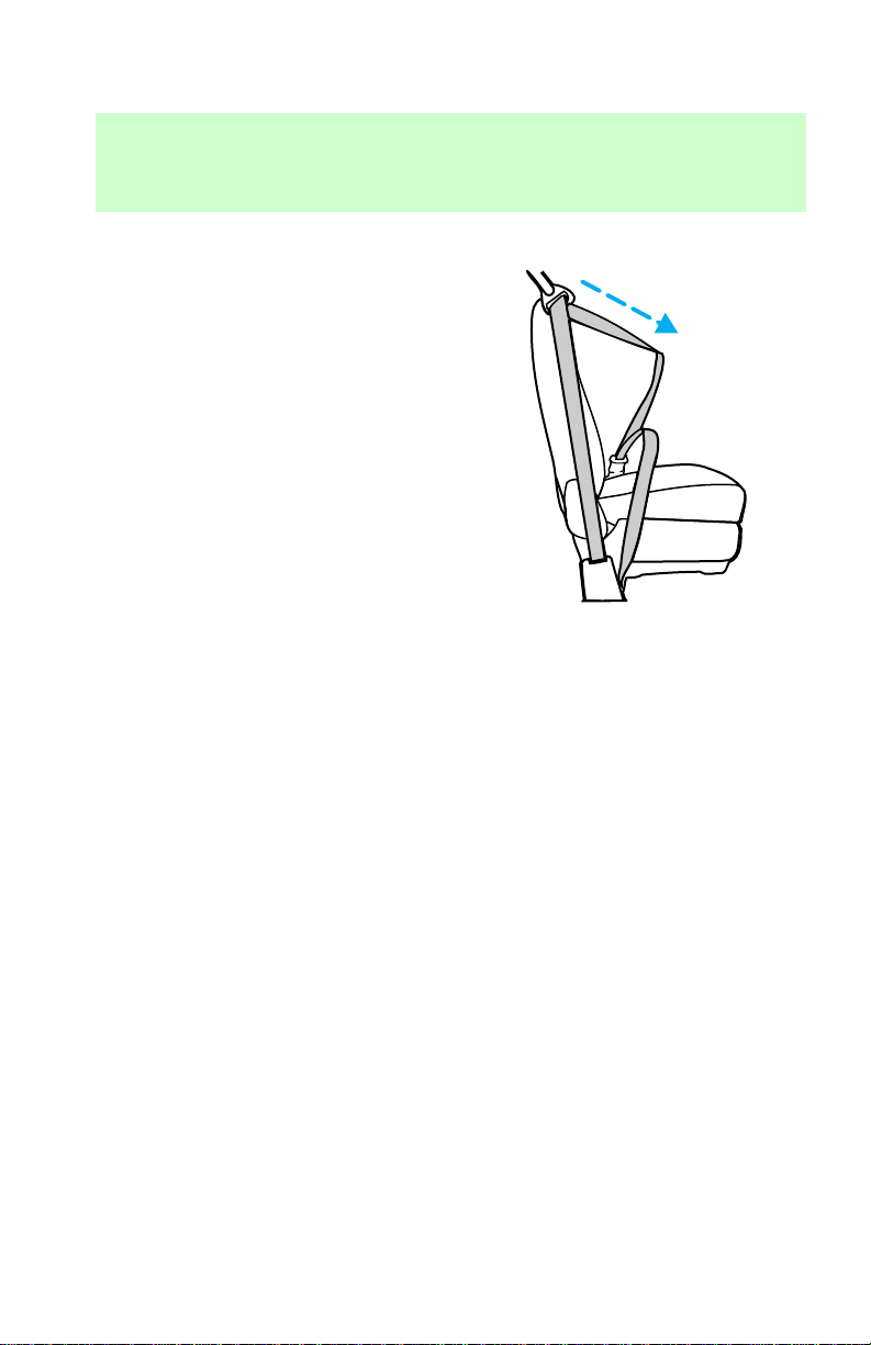
Automatic locking mode
In this mode, the safety belt is
locked in a certain position by the
occupant and remains locked until
the webbing is fully retracted.
The automatic locking mode is not
available on the driver belt.
When to use the automatic
locking mode
• When a tight lap/shoulder fit is
desired.
• Any time a child safety seat is
installed in the vehicle. Refer to
Children and infant or Child
safety seats later in this section.
47
Page 48
Seating and safety restraints
Using the automatic locking
mode
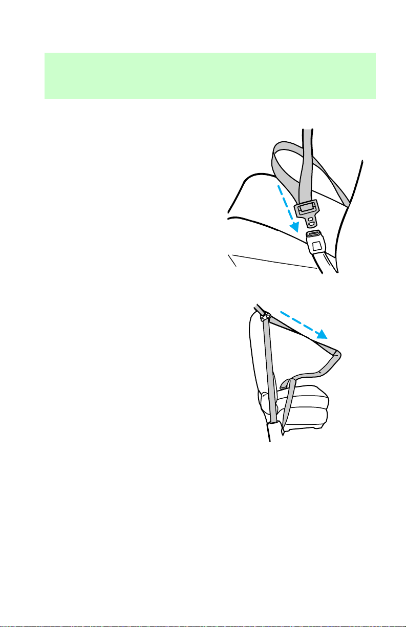
1. Buckle the combination lap and
shoulder belt.
2. Grasp the shoulder portion and
pull downward until the entire belt
is extracted.
3. Allow the belt to retract. As the
belt retracts, you will hear a
clicking sound. This indicates the
safety belt is now in the automatic
locking mode.
48
Page 49
Seating and safety restraints
Canceling the automatic locking
mode
Disconnect the combination
lap/shoulder belt and allow it to
retract completely to cancel the
automatic locking mode and
activate the vehicle sensitive
(emergency) locking mode.
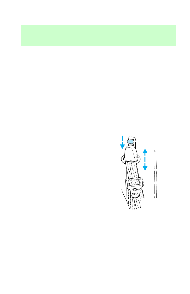
Front safety belt height
adjustment
Your vehicle has safety belt height
adjustments for the driver and
front passenger. Adjust the height
of the shoulder belt so the belt
rests across the middle of your
shoulder.
To lower the height of the shoulder
belt:
1. Push the button down
2. Slide down
To raise the height of the shoulder
belt:
1. Slide up
2. Pull down on the height
adjustment assembly to make sure
it is locked in place
49
Page 50

Seating and safety restraints
Lap belts
The lap belts in the center seating
position of the three-passenger
bench seat and both inboard seats
of the four-passenger bench seat
do not adjust automatically. You
must adjust them to fit snugly and
low as possible around your hips.
Do not wear the lap belt around
your waist.
Make sure you insert the tongue
into the correct buckle. If you
need to lengthen the belt, turn the
tongue at a right angle to the belt
and pull across your lap until it
reaches the buckle. If you need to
tighten the belt, pull the loose end
of the webbing until it is snug
across the hips. Shorten and fasten
the belt when not in use.
Safety belt extension assembly
If the safety belt assembly is too
short, even when fully extended,
20 cm (eight inches) can be added
to the safety belt assembly by
adding a safety belt extension
assembly. Safety belt extension
assemblies are available for front
or rear seating positions and are
not interchangeable.
• Front seating positions (part
number 611C22)
• Rear seating positions (part
number 611C22)
Safety belt extension assemblies
can be obtained from your dealer
at no cost.
50
Page 51

Seating and safety restraints
Use only extensions manufactured
by the same supplier as the safety
belt. Manufacturer identification is
located at the end of the webbing
on the label. Also, use the safety
belt extension only if the safety
belt is too short for you when fully
extended. Do not use extension to
change the fit of the shoulder belt
across the torso.
Safety belt indicator light and
warning chime
The seat belt warning light
illuminates in the instrument
cluster and a chime sounds to
remind the occupants to fasten
their safety belts.
Conditions of operation
If... Then...
The driver’s safety belt is not
buckled before the ignition key
is turned to ON...
The driver’s side safety belt is
buckled while the indicator
light is illuminated and the
warning chime is sounding...
The driver’s safety belt is
buckled before the ignition key
is turned to ON...
The safety belt indicator illuminates
and the warning chime/buzzer
sounds for four to eight seconds.
The safety belt warning chime turns
off.
The safety belt indicator
chime/buzzer remains off.
Safety belt inspection after a
collision, maintenance and care
Check the safety belt system
periodically to make sure that it
works properly and is not
damaged. Check the safety belts to
51
Page 52

Seating and safety restraints
make sure there are no nicks,
wears or cuts.
All safety belt assemblies,
including retractors, buckles, front
seat belt buckle support assemblies
(slide bar) (if so equipped),
shoulder belt height adjusters (if
so equipped), child safety seat
tether bracket assemblies (if so
equipped) and attaching hardware,
should be inspected after any
collision. Ford recommends that all
safety belt assemblies used in
vehicles involved in a collision be
replaced. However, if the collision
was minor and a qualified
technician finds that the belts do
not show damage and continue to
operate properly, they do not need
to be replaced. Safety belt
assemblies not in use during a
collision should also be inspected
and replaced if either damage or
improper operation is noted.
AIR BAG SUPPLEMENTAL
RESTRAINT SYSTEM (SRS)
Important air bag precautions
and warnings
Your vehicle is equipped with a
supplemental restraint system
designed to work with the safety
belts to help protect you and your
right front passenger in the event
of certain collisions described in
the section How does the air bag
supplemental restraint system
work?
52
Page 53

Seating and safety restraints
All occupants of the
vehicle, including the
driver, should always wear their
safety belts, failure to do so may
increase the risk of personal
injury in the event of a collision.
The right front passenger
air bag is not designed to
restrain occupants in the center
front seating position.
Do not place objects or
mount equipment on or
near the dashboard area,
steering wheel or in front of the
passenger that may come in
contact with a deploying air bag.
Failure to follow this instruction
may increase the risk of personal
injury in the event of a collision.
Do not attempt to service,
repair, or modify the Air
Bag Supplemental Restraint
System or its fuses. See your
Ford or Lincoln-Mercury dealer.
If you are close to an
inflating air bag, it could
seriously injure you. Sit against
the seatback and position your
seat such that it is as far back
from the steering wheel as
possible but still allows you to
properly control the vehicle.
53
Page 54
Seating and safety restraints
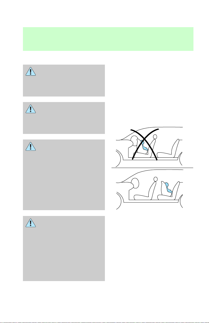
Children and air bags
Children should be placed
in the rear in an
appropriate child safety seat that
is properly secured to the
vehicle.
Children should always
wear their safety belts.
Failure to follow this instruction
may increase the risk of personal
injury in the event of a collision.
Rear-facing infant seats
MUST always be secured
in the rear seat. In vehicles
without a rear seat, a rear-facing
infant seat should be secured in
the front seat ONLY if your
vehicle does not have a
passenger side air bag or your
vehicle is equipped with a
passenger air bag deactivate
switch and the switch is turned
to “OFF.”
When using forward-facing
child safety seats in
vehicles with only two seating
positions so the forward-facing
child safety seat cannot be
placed in the rear of the vehicle,
move the passenger seat as far
back from the instrument panel
as possible. Never secure
rear-facing infant seats in the
front seat.
54
Page 55
Seating and safety restraints
For additional important safety
information on the proper use of
seat belts, child seats and infant
seats, please read the entire
Seating and safety restraints
chapter in this owner’s guide.
How does the air bag
supplemental restraint system
work?
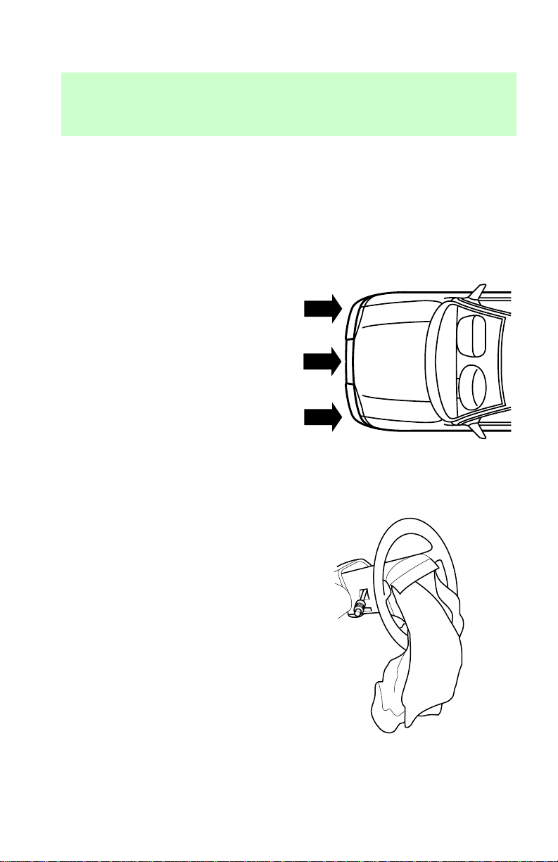
The Air Bag Supplemental
Restraint System is designed to
activate when the vehicle sustains
sufficient longitudinal (lengthwise)
deceleration that is equal to or
greater than hitting an immovable
barrier head on at a range of about
12–24 km/h (8–14 mph).
The fact that the air bags did not
inflate in a collision does not mean
that something is wrong with the
system. Rather, it means the forces
were not of the type sufficient to
cause activation.
If the vehicle experiences
sufficient longitudal deceleration,
the system is activated and the air
bags inflate rapidly. After the air
bag inflates, it will quickly deflate.
This occurs so quickly that some
people may not even realize that
the air bag inflated.
After the air bag deployment, you
may notice a smoke-like, powdery
residue or smell the burnt
propellant (which is used to
lubricate the air bag) or sodium
compounds, such as sodium
carbonates (e.g., baking soda) that
result from the combustion process
55
Page 56

Seating and safety restraints
that inflates the air bag. Small
amounts of sodium hydroxide may
be present which may irritate the
skin and eyes, but none of the
residue is toxic.
The Air Bag Supplemental
Restraint System will reduce, but
not eliminate all injuries in an
accident.
Several air bag system
components get hot after
inflation. Do not try to touch
them after inflation.
The air bag will only
inflate once and the
pretensioners (if equipped) will
only activate once. The system is
designed to function on a
one-time-only basis. If the air bag
is inflated, THE AIR BAG WILL
NOT FUNCTION AGAIN AND
MUST BE REPLACED
IMMEDIATELY. If the
pretensioners activate (if
equipped), THE
PRETENSIONERS WILL NOT
FUNCTION AGAIN AND MUST
BE REPLACED IMMEDIATELY.
If the pretensioners are not
replaced, this will increase the
risk of injury in a subsequent
collision.
The SRS consists of:
• driver and passenger air bag
modules (which include the
inflators and air bags),
56
Page 57

Seating and safety restraints
• one or more impact and safing
sensors,
• a readiness light and tone,
• driver and front passenger
safety belt buckle pretensioners
• and the electrical wiring which
connects the components.
The diagnostic module monitors its
own internal circuits and the
supplemental air bag electrical
system readiness (including the
impact sensors), the system wiring,
the air bag system readiness light,
the air bag back up power and the
air bag ignitors.
Determining if the system is
operational
The SRS uses a readiness light in
the instrument cluster or a tone to
indicate the condition of the
system. Refer to the Air bag
readiness section in the
Instrumentation chapter. Routine
maintenance of the air bag is not
required.
A difficulty with the system is
indicated by one or more of the
following:
• The readiness light will either
flash or stay lit.
• The readiness light will not
illuminate immediately after
ignition is turned on.
• A group of five beeps will be
heard. The tone pattern will
repeat periodically until the
problem and light are repaired.
57
Page 58

Seating and safety restraints
If any of these things happen, even
intermittently, have the SRS
serviced at your dealership or by a
qualified technician immediately.
Unless serviced, the system may
not function properly in the event
of a collision.
Disposal of air bags and air bag
equipped vehicles
For disposal of air bags or air bag
equipped vehicles, see your local
dealership or qualified technician.
Air bags MUST BE disposed of by
qualified personnel.
SAFETY RESTRAINTS FOR
CHILDREN
Important child restraint
precautions
You are required by law to use
safety restraints for children in the
U.S. and Canada. If small children
ride in your vehicle (generally
children who are four years old or
younger and who weigh 18 kg [40
lbs] or less), you must put them in
safety seats made especially for
children. Check your local and
state laws for specific
requirements regarding the safety
of children in your vehicle.
Never let a passenger hold
a child on his or her lap
while the vehicle is moving. The
passenger cannot protect the
child from injury in a collision.
58
Page 59

Seating and safety restraints
Always follow the instructions and
warnings that come with any infant
or child restraint you might use.
Children should be placed in the
rear seat of your vehicle. Accident
statistics suggest that children are
safer when properly restrained in
the rear seating positions than in
the front seating position.
Install forward-facing convertible
safety seats only in vehicle seating
positions equipped with
lap-shoulder belts. Forward facing
convertible safety seats can be
used in the center of the
three-passenger second row bench
seat only if a top tether strap is
used. Ford recommends placing
forward-facing safety seats in the
second row and using safety seats
with top tether straps for added
protection. For more information
on top tether straps see attaching
safety seats with tether straps in
this section.
Any booster seat that places the
vehicle’s lap belt or shoulder belt
around a shield above and ahead
of the child’s hips should not be
used in this vehicle.
Do not use a
forward-facing safety seat
or an infant seat in the last row
of a 12- or 15-passenger Club
Wagon.
59
Page 60

Seating and safety restraints
Children and safety belts
Children who are too large for
child safety seats (as specified by
your child safety seat
manufacturer) should always wear
safety belts.
Follow all the important safety
restraint and air bag precautions
that apply to adult passengers in
your vehicle.
If the shoulder belt portion of a
combination lap and shoulder belt
can be positioned so it does not
cross or rest in front of the child’s
face or neck, the child should wear
the lap and shoulder belt. Moving
the child closer to the center of
the vehicle may help provide a
good shoulder belt fit.
To improve the fit of lap and
shoulder belts on children who
have outgrown child safety seats,
Ford recommends use of a
belt-positioning booster seat that is
labelled as conforming to all
Federal motor vehicle safety
standards. Belt-positioning booster
seats raise the child and provide a
shorter, firmer seating cushion that
encourages safer seating posture
and better fit of lap and shoulder
belts on the child. A
belt-positioning booster should be
used if the shoulder belt rests in
front of the child’s face or neck, or
if the lap belt does not fit snugly
on both thighs, or if the thighs are
too short to let the child sit all the
way back on the seat cushion
when the lower legs hang over the
60
Page 61

Seating and safety restraints
edge of the seat cushion. You may
wish to discuss the special needs
of your child with your
pediatrician.
Child and infant or child safety
seats
Carefully follow all of the
manufacturer’s instructions
included with the safety seat you
put in your vehicle. If you do not
install and use the safety seat
properly, the child may be
injured in a sudden stop or
collision.
Ford recommends the use of a
child safety seat having a top
tether strap. Install the child safety
seat in a seating position which is
capable of providing a tether
anchorage. For more information
on top tether straps see Attaching
safety seats with tether straps in
this chapter.
When installing a child safety seat:
• Use the correct safety belt
buckle for that seating position.
• Make sure the tongue is
securely fastened in the buckle.
• Keep the buckle release button
pointing up and away from the
safety seat, with the tongue
between the child seat and the
release button, to prevent
accidental unbuckling.
• Place seatbacks in the upright
position.
61
Page 62
Seating and safety restraints
• Put the safety belt in the
automatic locking mode. Refer
to Using the automatic locking
mode in this chapter.
Installing child safety seats in
combination lap and shoulder
belt seating positions
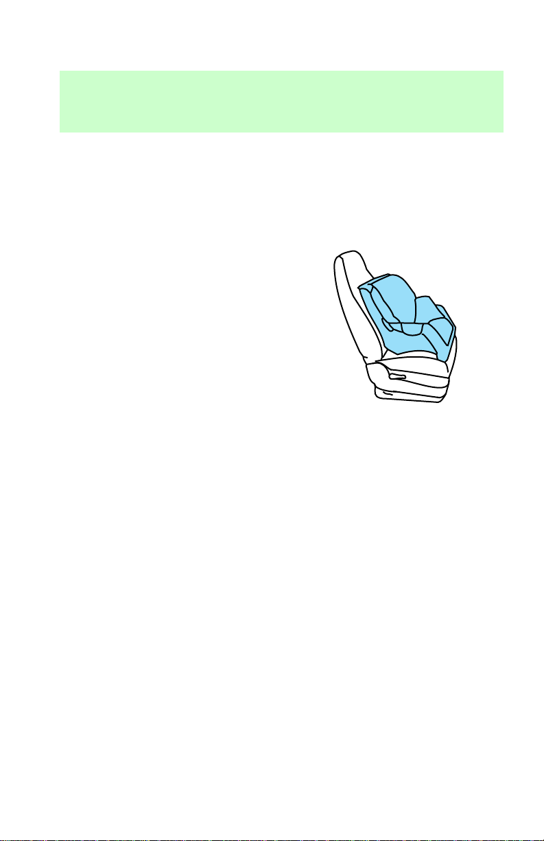
1. Position the child safety seat in
a seat with a combination lap and
shoulder belt.
If you choose to install a child
safety seat in the front passenger
seat, move the seat as far back as
possible.
62
Page 63
Seating and safety restraints
Rear-facing child seats or
infant carriers should
never be placed in the front
seats.
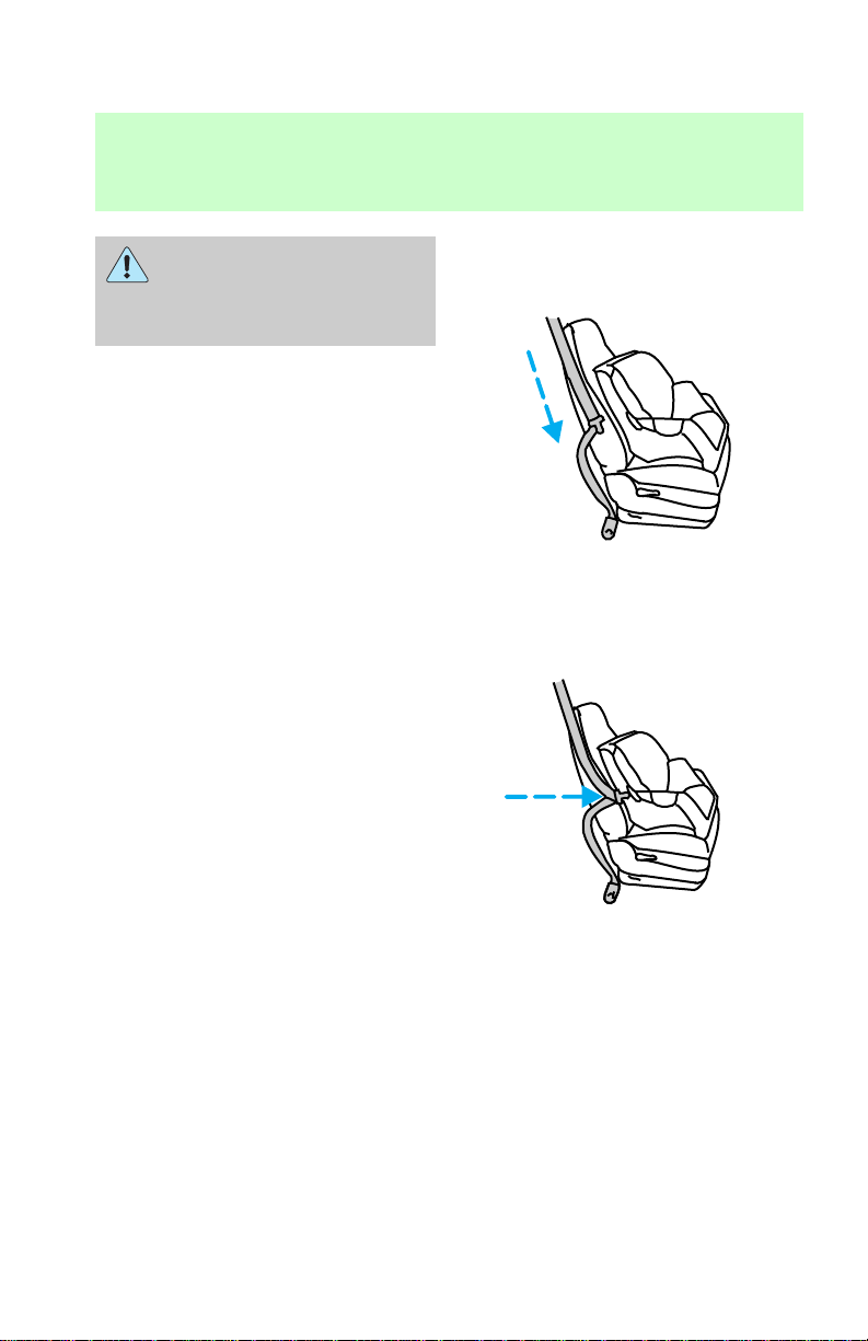
2. Pull down on the shoulder belt
and then grasp the shoulder belt
and lap belt together.
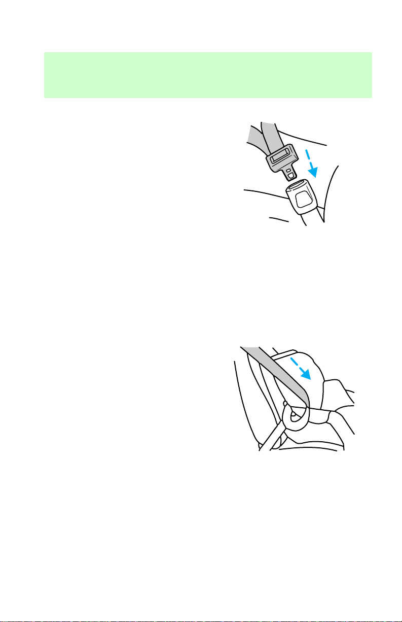
3. While holding the shoulder and
lap belt portions together, route
the tongue through the child seat
according to the child seat
manufacturers’ instructions. Be
63
Page 64
Seating and safety restraints
sure the belt webbing is not
twisted.
4. Insert the belt tongue into the
proper buckle for that seating
position until you hear and feel the
latch engage. Make sure the
tongue is latched securely by
pulling on it.
PRESS
5. To put the retractor in the
automatic locking mode, grasp the
shoulder portion of the belt and
64
Page 65
Seating and safety restraints
pull downward until all of the belt
is extracted and a click is heard.
6. Allow the belt to retract. The
belt will click as it retracts to
indicate it is in the automatic
locking mode.
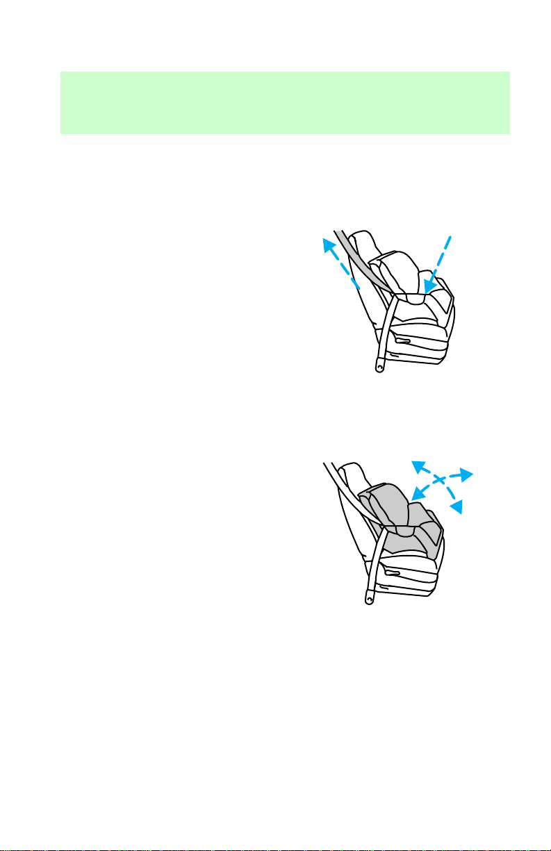
7. Pull the lap belt portion across
the child seat toward the buckle
and pull up on the shoulder belt
while pushing down with knee on
the child seat.
8. Allow the safety belt to retract
to remove any slack in the belt.
9. Before placing the child in the
seat, forcibly tilt the seat forward
and back to make sure the seat is
securely held in place.
10. Try to pull the belt out of the
retractor to make sure the
retractor is in the automatic
locking mode (you should not be
65
Page 66

Seating and safety restraints
able to pull more belt out). If the
retractor is not locked, unbuckle
the belt and repeat steps two
through nine.
Check to make sure the child seat
is properly secured before each
use.
Installing a child safety seat at
the rear center seating position
with locking adjustable lap belt
1. Lengthen the lap belt. To
lengthen the belt, hold tongue so
that its bottom is perpendicular to
the direction of webbing while
sliding the tongue up the webbing.
2. Place the child safety seat in the
center seating position.
3. Route the tongue and webbing
through the child seat according to
the child seat manufacturer’s
instructions.
4. Insert the belt tongue into the
proper buckle for the center
seating position until you hear a
snap and feel it latch. Make sure
the tongue is securely fastened to
the buckle by pulling on tongue.
5. Push down on the child seat
while pulling on the loose end of
the lap belt webbing to tighten the
belt.
6. Before placing the child into
child seat, forcibly tilt the child
seat from side-to-side and in
forward directions to ensure that
the seat is held securely in place.
If the child seat moves excessively,
66
Page 67

Seating and safety restraints
repeat steps 5 and 6, or properly
install the child seat in a different
seating position.
Attaching safety seats with
tether straps
Some manufacturers make safety
seats that include a tether strap
that goes over the back of the
vehicle seat and attaches to an
anchoring point. Other
manufacturers offer the tether
strap as an accessory. Contact the
manufacturer of your child safety
seat for information about ordering
a tether strap.
Tether anchorage
Children should be placed
in the rear in an
appropriate child safety seat that
is properly secured to the
vehicle.
Rear-facing infant seats
must always be secured in
the rear seat. In vehicles without
a rear seat, a rear-facing infant
seat should be secured in the
front seat only if your vehicle
does not have a passenger side
air bag or your vehicle is
equipped with a passenger air
bag deactivate switch and the
switch is turned to “OFF.”
67
Page 68
Seating and safety restraints
When using forward-facing
child safety seats in
vehicles with only two seating
positions so the forward-facing
child safety seat cannot be
placed in the rear of the vehicle,
move the passenger seat as far
back from the instrument panel
as possible.
Front passenger seating
position
The front passenger seating
position does not require any
tether hardware. The tether can be
attached directly to the rear of the
front seat.
1. Position the child safety seat on
the front right-hand passenger
seat.
2. Adjust the front right-hand
68
Page 69
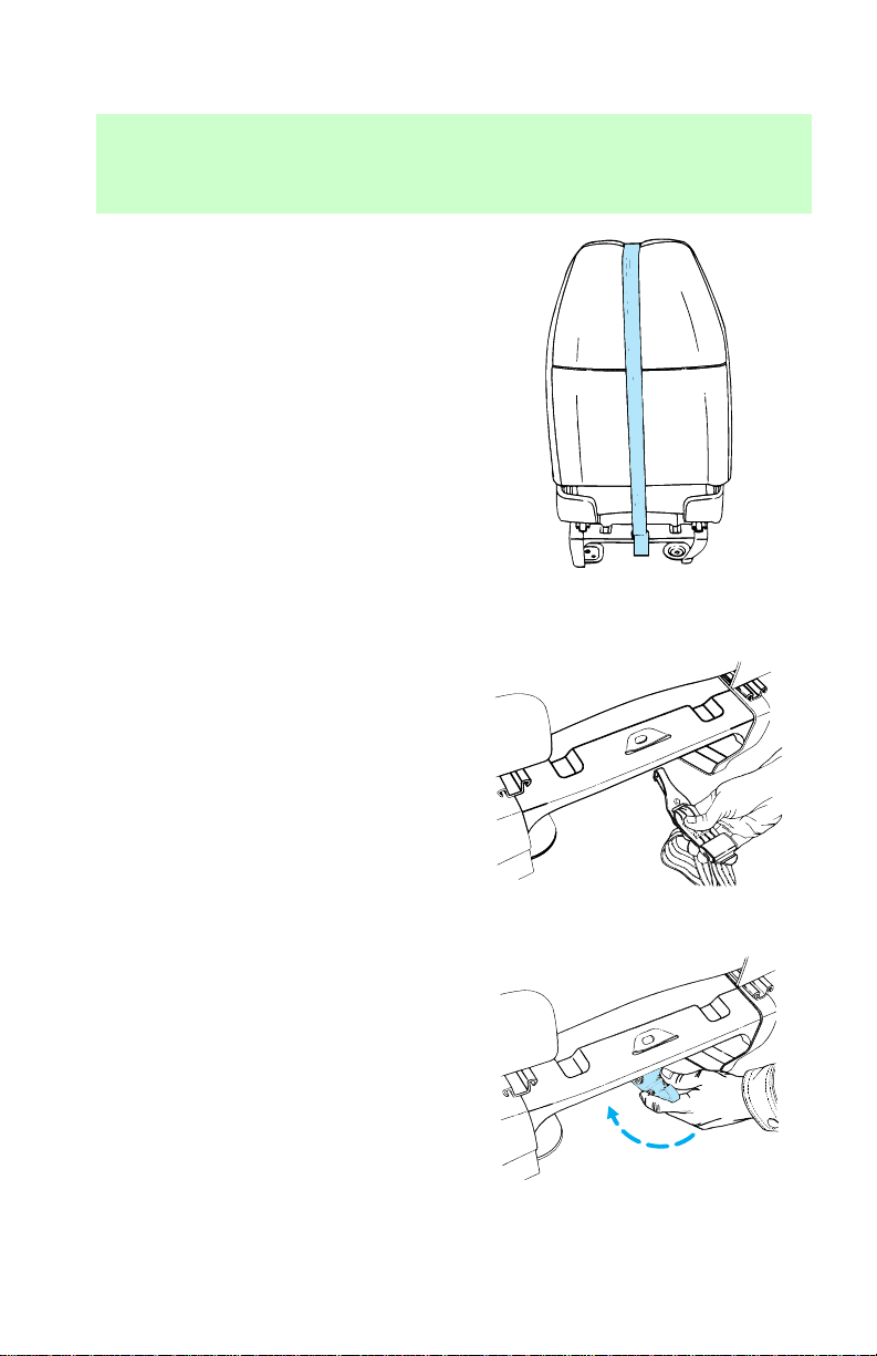
Seating and safety restraints
passenger seat full forward.
3. Route the child safety seat
tether strap over the back of the
front right-hand passenger seat as
shown.
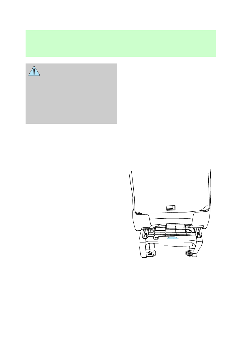
4. Grasp the tether strap and
position it to the seat pedestal as
shown.
69
Page 70
Seating and safety restraints
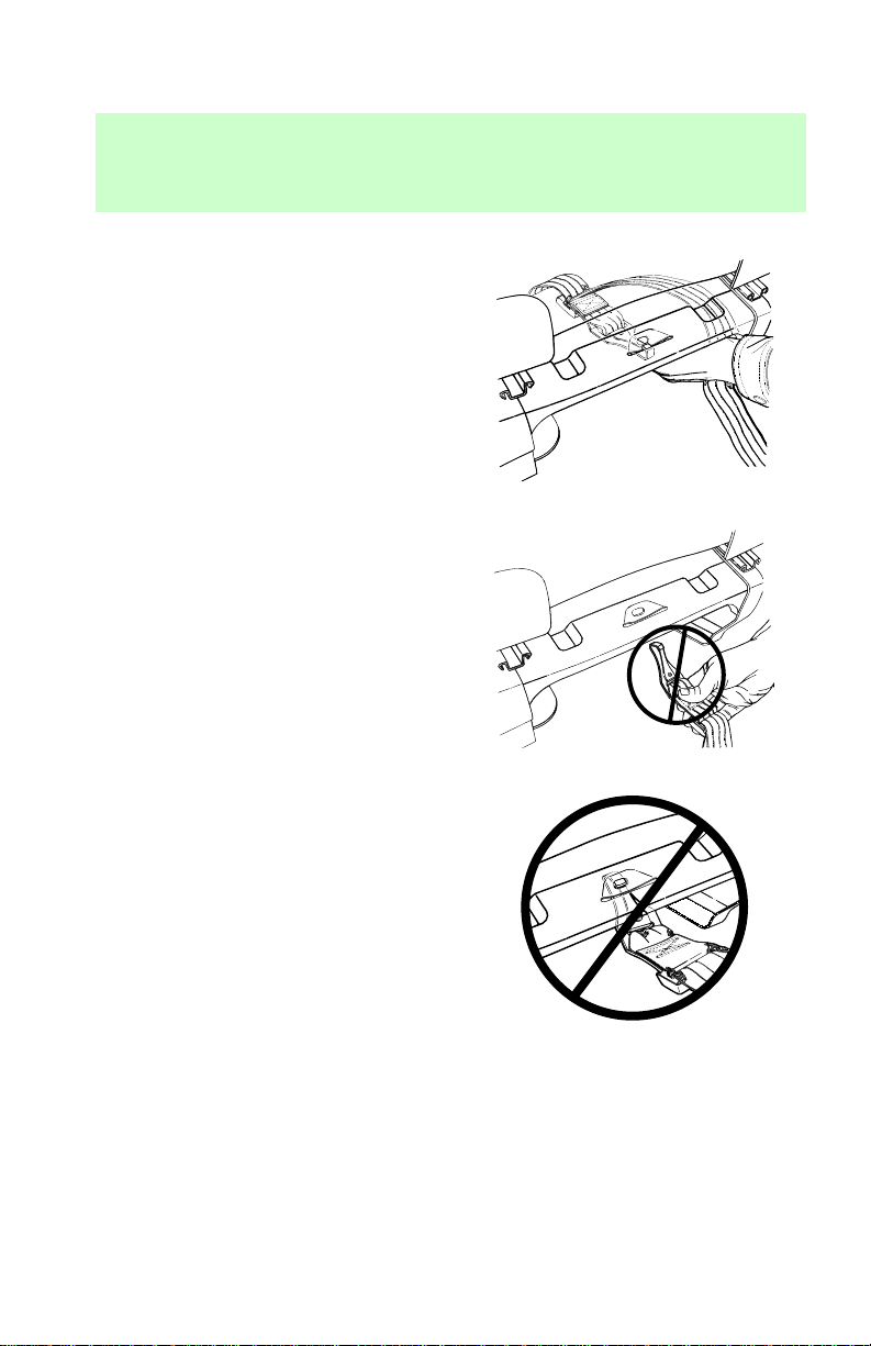
5. Rotate the tether strap as
shown.
6. Clip the tether strap to the seat
pedestal as shown.
Do not clip the tether strap to the
seat pedestal as shown.
If the tether strap is clipped
incorrectly (as shown) the child
safety seat may not be retained
70
Page 71
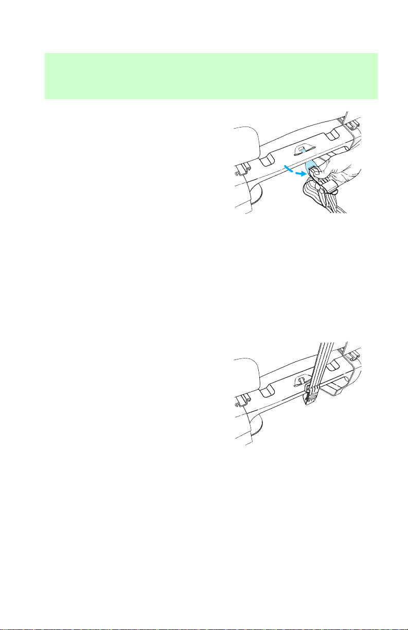
Seating and safety restraints
properly in the event of a collision.
7. Rotate the tether strap clip as
shown.
8. Adjust the front right-hand
passenger seat to the full rearward
position.
9. Refer to the instructions in this
section under Installing child
safety seats in combination lap
and shoulder belt seating
positions to secure the child
safety seat.
10. Tighten the child safety seat
tether strap according to the
manufacturers instructions.
For additional important safety
information on the proper use of
seatbelts, child seats and infant
seats, please read the entire
Seating and safety restraints
chapter in this owner’s guide.
71
Page 72
Seating and safety restraints
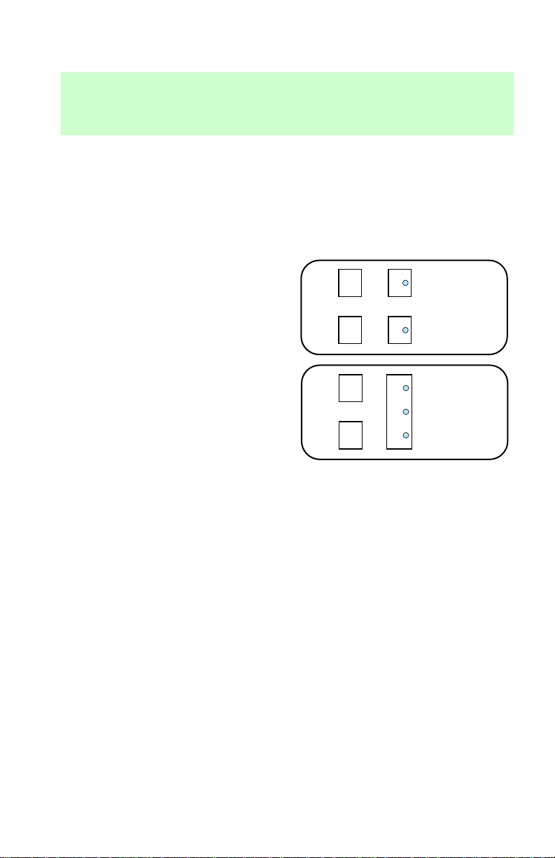
Rear seating positions
Attachment holes have been
provided in your vehicle to attach
anchor hardware, if required.
Tether anchor hardware kits (Part
No. 613D74) including instructions,
may be obtained at no charge from
any Ford dealer.
• Second row bucket seats (at
rear of lower seat frame)
• 3–passenger bench seat (on rear
rail of seat cushion frame)
72
Page 73

STARTING YOUR VEHICLE
Important safety precautions
A computer system controls the
engine’s idle revolutions per
minute (RPM). When the engine
starts, the idle RPM runs faster to
warm the engine. If the engine idle
speed does not slow down
automatically, have the vehicle
checked. Do not allow the vehicle
to idle for more than ten minutes.
Extended idling at high
engine speeds can produce
very high temperatures in the
engine and exhaust system,
creating the risk of fire or other
damage.
Do not park, idle, or drive
your vehicle in dry grass
or other dry ground cover. The
emission system heats up the
engine compartment and exhaust
system, which can start a fire.
Starting
Do not start your vehicle
in a closed garage or in
other enclosed areas. Exhaust
fumes can be toxic. Always open
the garage door before you start
the engine. See Guarding
against exhaust fumes in this
chapter for more instructions.
73
Page 74

Starting
If you smell exhaust fumes
inside your vehicle, have
your dealer inspect your vehicle
immediately. Do not drive if you
smell exhaust fumes.
Preparing to start the vehicle
Engine starting is controlled by the
spark ignition system. This system
meets all Canadian
Interference-Causing Equipment
standard requirements regulating
the impulse electrical field strength
of radio noise.
When starting a fuel-injected
engine, avoid pressing the
accelerator before or during
starting. Only use the accelerator
when you have difficulty starting
the engine. For more information
on starting the vehicle, refer to
Starting the vehicle in this
chapter.
Before starting the vehicle:
1. Make sure all vehicle occupants
have buckled their safety belts. For
more information on safety belts
and their proper usage, refer to
74
Page 75
the Seating and safety restraints
chapter.
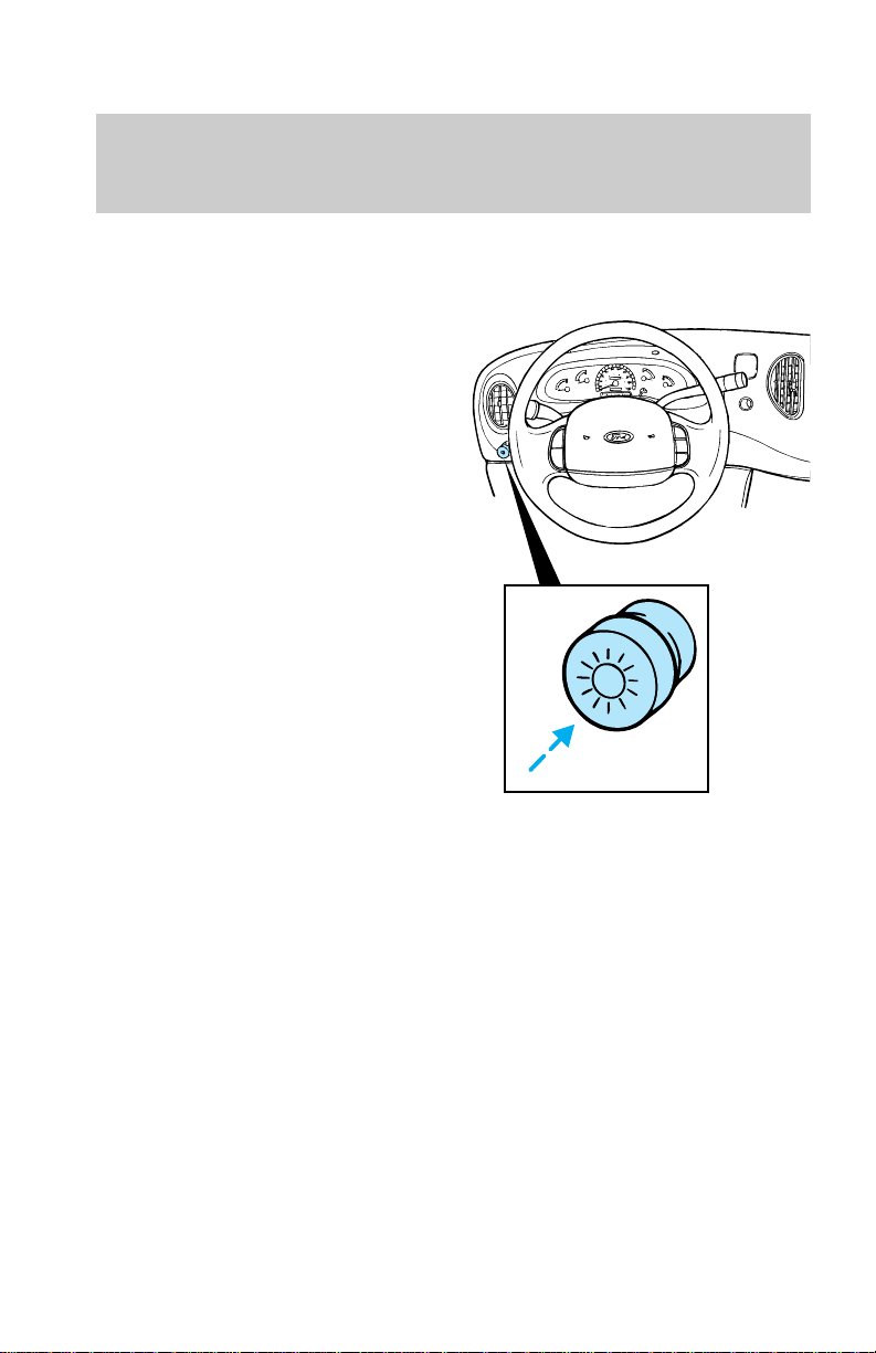
2. Make sure the headlamps and
vehicle accessories are off.
Starting
75
Page 76
Starting
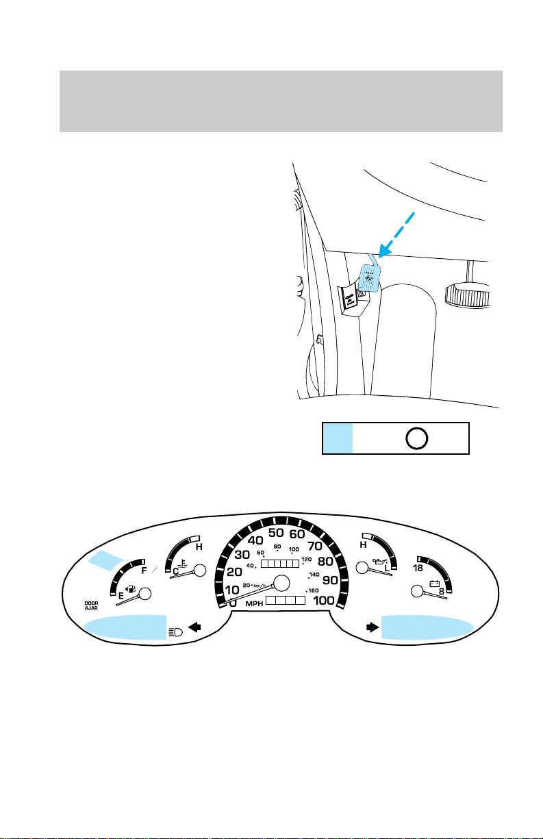
• Make sure the parking brake is
set.
• Make sure the gearshift is in P.
3. Turn the key to the ON position
(without turning the key to
START.)
L
A
M
R
O
N
BRAKE
76
000000
0000
PRN 21
D
N
O
R
M
A
L
N
O
R
M
A
L
Page 77
Make sure the corresponding lights
illuminate briefly. If a light fails to
illuminate, have the vehicle
serviced.
• If the driver’s safety belt is
fastened, the
illuminate.
STARTING PROCEDURE
Starting the engine
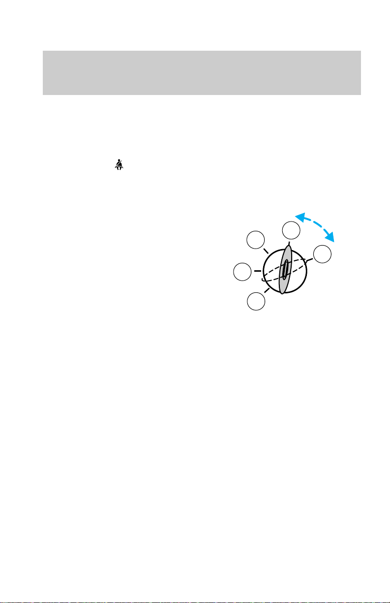
1. Turn the key to 5 (Start)
without pressing the accelerator.
The key will return to 4 (On).
2. If the engine does not start
within five seconds, wait ten
seconds and try again.
3. If the engine does not start in
two attempts OR the temperature
is below —12°C (10°F), depress
accelerator and start the engine
while holding the accelerator
down. Release accelerator when
engine starts.
4. After idling for a few seconds,
apply the brake and release the
parking brake.
light does not
Starting
4
3
5
2
1
Using the engine block heater
(if equipped)
An engine block heater warms the
engine coolant, which improves
starting, warms up the engine
77
Page 78

Starting
faster and allows the
heater-defroster system to respond
quickly. They are strongly
recommended if you live in a
region where temperatures reach
—23°C (–10°F) or below.
For best results, plug the heater in
at least three hours before starting
the vehicle. Using the heater for
longer than three hours will not
harm the engine, so the heater can
be plugged in the night before
starting the vehicle.
To prevent electrical
shock, do not use your
heater with ungrounded
electrical systems or
two-pronged (cheater) adapters.
Guarding against exhaust
fumes
Although odorless and colorless,
carbon monoxide is present in
exhaust fumes. Take precautions
to avoid its dangerous effects.
If you ever smell exhaust
fumes of any kind inside
your vehicle, have your dealer
inspect and fix your vehicle
immediately. Do not drive if you
smell exhaust fumes. These
fumes are harmful and could kill
you.
Have the exhaust and body
ventilation systems checked
whenever:
• the vehicle is raised for service
78
Page 79
• the sound of the exhaust system
changes
• the vehicle has been damaged in
a collision
Important ventilating
information
If the engine is idling while the
vehicle is stopped in a closed area
for long periods of time, open the
windows at least 2.5 cm (1 in).
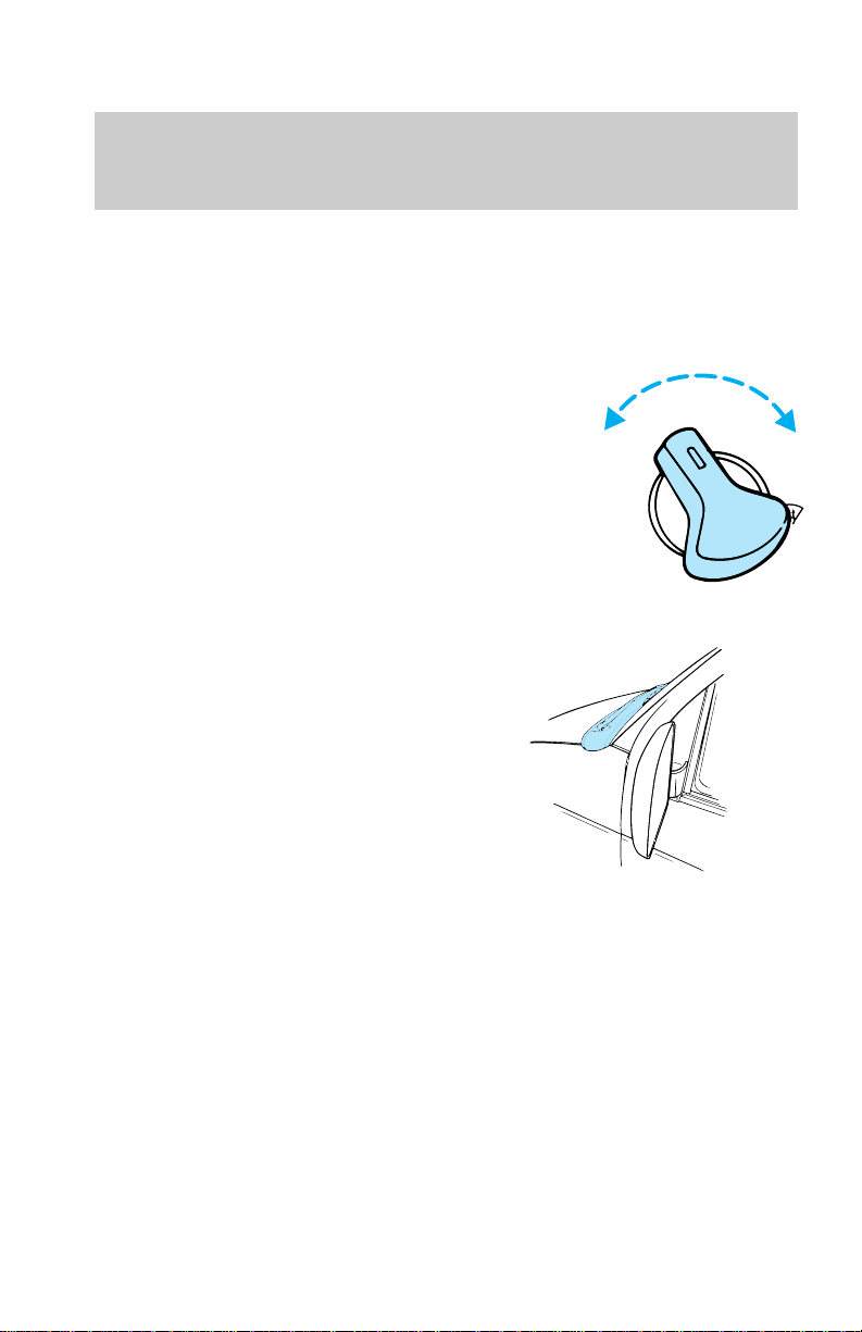
Adjust the heating or air
conditioning (if equipped) to bring
in fresh air.
Improve vehicle ventilation by
keeping all air inlet vents clear of
snow, leaves and other debris.
NORM
A C
/
MAX
A C
/
Starting
VENT
OFF
FLR
MIX
79
Page 80

Driving
BRAKES
Your brakes are self-adjusting.
Refer to the “Service Guide” for
maintenance scheduling.
Anti-lock brake system (ABS) (if
equipped)
The ABS operates by detecting the
onset of wheel lock up during
brake applications and
compensating for this tendency.
The front wheels are prevented
from locking even when the brakes
are firmly applied. The
accompanying illustration depicts
the advantage of an ABS equipped
vehicle (on bottom) to a non-ABS
equipped vehicle (on top) during
hard braking.
Using ABS
• In an emergency, apply full force
on the brake. The ABS will be
activated immediately, thus
allowing you to retain full
steering control of your vehicle
and, providing there is sufficient
space, will enable you to avoid
obstacles and bring the vehicle
to a quiet stop.
• We recommend that you
familiarize yourself with this
braking technique. However,
avoid taking any unnecessary
risks.
Parking brake
The parking brake should be used
whenever you park your vehicle. It
is not designed to stop a moving
80
Page 81
vehicle. However, if the normal
brakes fail, the parking brake can
be used to stop your vehicle in an
emergency. Since the parking
brake applies only the rear brakes,
the vehicle’s stopping distance will
increase greatly and the handling
of your vehicle will be adversely
affected.
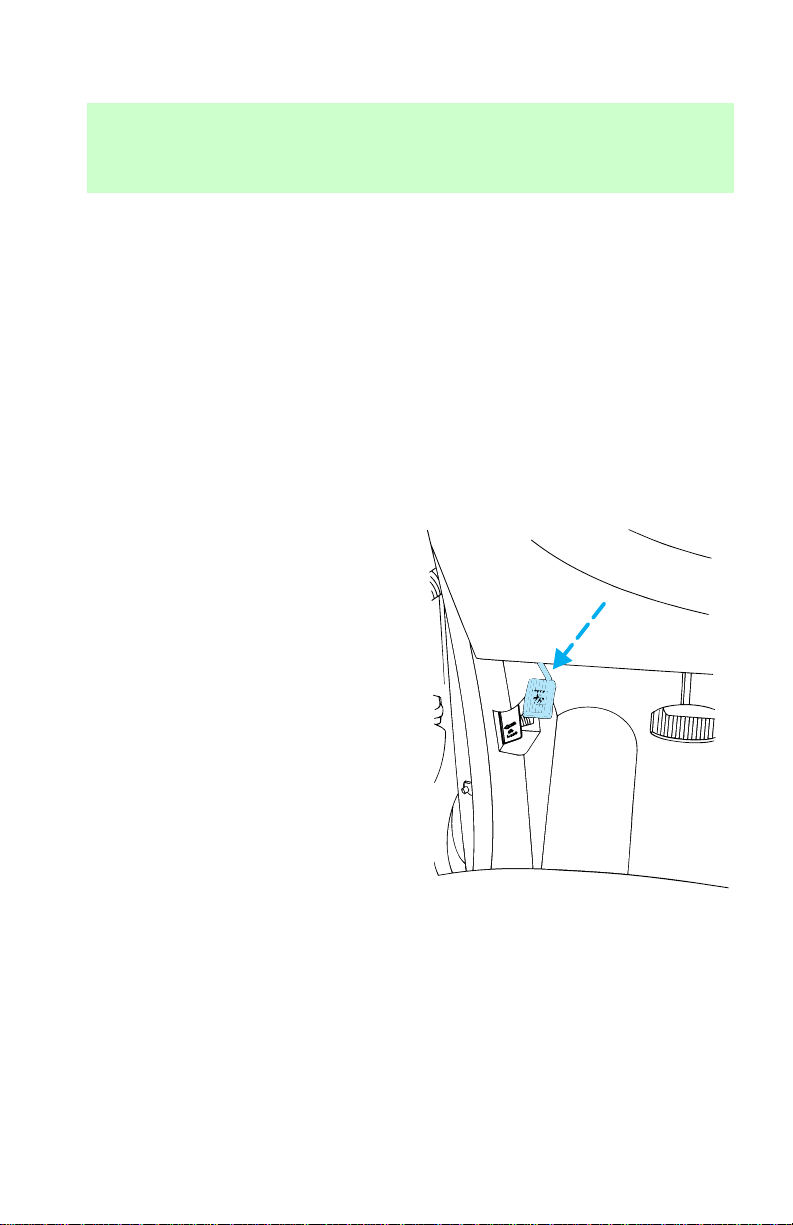
Setting the parking brake
The brake light in the instrument
cluster will illuminate and remain
illuminated (when the ignition
switch is turned to ON) until the
parking brake is released.
• Fully depress the parking brake
pedal.
Driving
81
Page 82
Driving
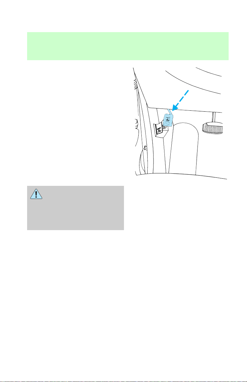
Releasing parking brake
• Push parking brake pedal down
firmly, then release.
If the parking brake is fully
released, but the Brake
System light remains on, have
the brakes checked immediately.
They may not be working
properly.
STEERING YOUR VEHICLE
If the amount of effort needed to
steer your vehicle changes at a
constant speed, have the vehicle
power steering system checked.
Never hold the steering wheel to
the extreme left or right for more
than five seconds if the engine is
running. This can damage the
power steering pump.
After any severe impact or
collision involving the front end,
observe the steering wheel
alignment. If the spoke of the
82
Page 83
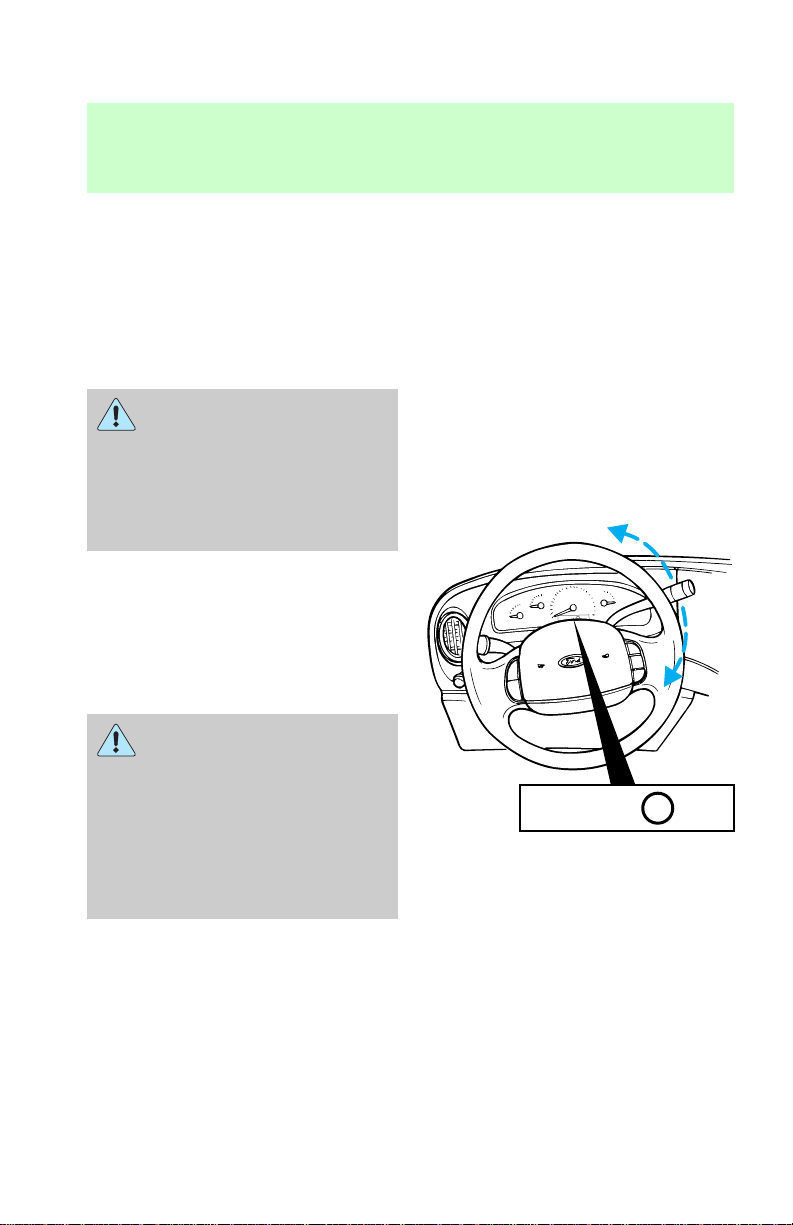
steering wheel seem to be in a
different position while going
straight down the road, have the
suspension and steering checked
for possible damage.
AUTOMATIC TRANSMISSION
OPERATION
Hold the brake pedal down
while you move the
gearshift lever from position to
position. If you do not hold the
brake pedal down, your vehicle
may move unexpectedly and
injure someone.
Pull the gearshift lever towards
you and downward to move the
automatic gearshift.
P (Park) — Always come to a
complete stop before shifting into
or out of P (Park).
When you leave your
vehicle, place the gearshift
lever in P (Park). Set the
parking brake fully, and shut off
the engine. Never park your
vehicle in N (Neutral). If you do
not take these precautions, your
vehicle may move suddenly and
injure someone.
Driving
D
P RN 21
P RN 21
D
R (Reverse) — Always come to a
complete stop before shifting into
or out of R (Reverse).
83
Page 84
Driving
N (Neutral) — Vehicle is free to
roll.
D
(Overdrive)— The normal
driving position for the best fuel
economy. Transmission operates
automatically in gears one through
four.
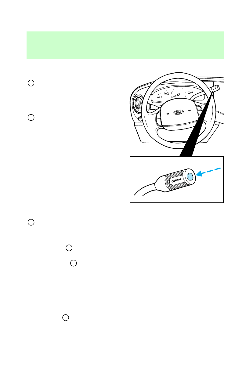
D
(Overdrive) can be deactivated
by pressing the transmission
control switch on the end of the
gearshift lever. The transmission
control indicator light (TCIL) (the
word “OFF”) on the end of the
gearshift lever will remain off.
D (Drive) — Not shown on the
display. Activate by pressing the
transmission control switch on the
end of the gearshift lever. The
TCIL (the word “OFF”) will
illuminate on the gearshift lever.
Transmission operates in gears one
through three. D (Drive) provides
more engine braking than
D
(Overdrive) and is useful
whenever driving conditions (i.e.,
city traffic, hilly terrain, etc.) cause
the transmission to excessively
shift between
D (Drive).
Also deactivate
when:
• driving with a heavy load
• towing a trailer up or down
steep hills
• additional engine braking is
desired
To return to
mode, press the transmission
control switch. The TCIL (the
D
(Overdrive) and
D
(Overdrive)
D
(Overdrive)
84
Page 85

word “OFF”) will no longer be
illuminated.
Each time the vehicle is started,
the transmission will automatically
return to normal overdrive mode
and you must press the TCS to
deactivate overdrive again if you
do not want overdrive operation.
2 (Second) — Use 2 (Second) to
start-up on slippery roads or to
provide additional engine braking
on downgrades. Transmission
operates in first and second gears.
1 (Low) — Use 1 (Low) to
provide maximum engine braking
on steep downgrades. Upshifts can
be made by shifting to 2 (Second)
D
or to
(Low) at higher speeds causes a
shift to 2 (Second), and will shift
to 1 (Low) after vehicle
decelerates to the proper speed.
Brake-shift interlock
The brake-shift interlock feature
prevents you from shifting from P
(Park) unless the brake pedal is
depressed (with the ignition in the
ON position). If you cannot move
the gearshift out of P (Park) with
the brake pedal depressed:
1. Turn ignition key to Off.
2. Apply the parking brake.
3. Turn ignition key to Lock and
remove the key.
4. Re-insert the ignition key and
turn it to Off.
(Overdrive). Selecting 1
Driving
85
Page 86

Driving
5. Shift the transmission to N
(Neutral).
6. Start the vehicle.
If you need to use the above
procedure, it is possible that a fuse
has blown and your brakelamps
may not be functioning. Refer to
the Roadside emergencies
chapter for instructions on
replacing fuses.
Do not drive your vehicle
until you verify that the
brakelamps are working.
VEHICLE LOADING
It is extremely dangerous
to ride in a cargo area,
inside or outside of a vehicle. In
a collision, people riding in these
areas are more likely to be
seriously injured or killed. Do not
allow people to ride in any area
of your vehicle that is not
equipped with seats and safety
belts. Be sure everyone in your
vehicle is in a seat and using a
safety belt properly.
Before loading a vehicle, familiarize
yourself with the following terms:
• Base Curb Weight: Weight of
the vehicle including any
standard equipment, fluids,
lubricants, etc. It does not
include passengers or
aftermarket equipment.
86
Page 87

• Payload: Combined maximum
allowable weight of cargo,
passengers and optional
equipment. The payload equals
Gross Vehicle Weight Rating
(GVWR) minus base curb
weight.
• GVW (Gross Vehicle Weight):
Base curb weight plus the
payload weight (including
passengers, cargo and optional
equipment. Remember, the GVW
is not a limit or a specification.
• GVWR (Gross Vehicle Weight
Rating): Maximum total weight
of the base vehicle, passengers,
optional equipment and cargo.
The GVWR is specific to each
particular vehicle and is listed
on the Safety Compliance
Certification Label on the driver
door pillar.
• GAWR (Gross Axle Weight
Rating): Carrying capacity for
each axle system (front and
rear). This amount is specific to
each particular vehicle and is
listed on the Safety Compliance
Certification Label on the driver
door pillar.
• GCWR (Gross Combined
Weight Rating): Maximum
combined weight of the towing
vehicle (including passengers
and cargo) and the trailer. The
GCWR indicates the maximum
loaded weight that the vehicle is
allowed to tow.
• Maximum trailer weight:
Maximum weight of a trailer the
Driving
87
Page 88

Driving
loaded vehicle (including
passengers and cargo) is
permitted to tow. It is
determined by subtracting the
weight of the loaded towing
vehicle from the GCWR of the
towing vehicle.
• Trailer weight range:
Specified weight range that the
trailer must fall within that
ranges from zero to the
maximum trailer weight rating.
Remember to figure in the tongue
load of your loaded trailer when
figuring the total weight of your
vehicle and rear axle loads.
Do not use replacement tires with
lower weight capacities than the
original because they may lower
the vehicle’s GVWR and GAWR
limitations. Replacement tires with
a higher weight limit than the
originals do not increase the
GVWR and GAWR limitations.
88
Page 89
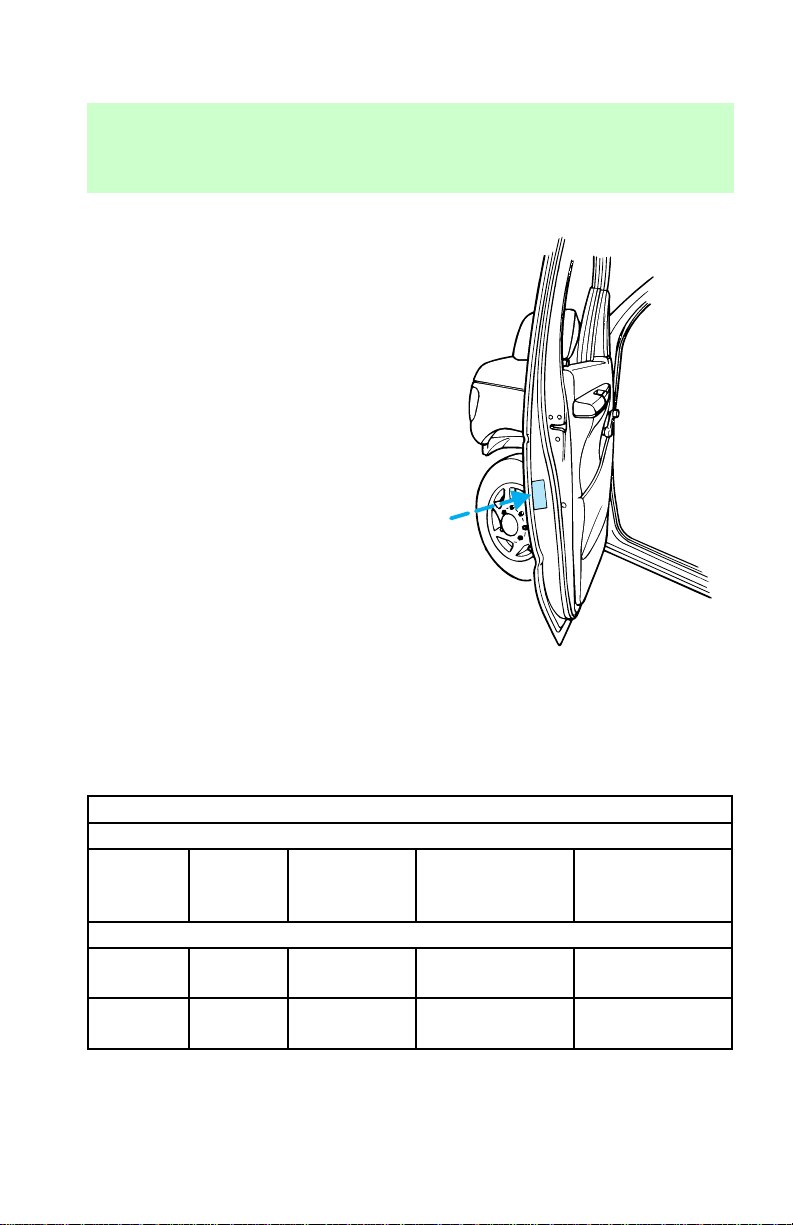
Calculating the load your
vehicle can carry/tow
1. Use the Safety Compliance
Certification Label to find the axle
code number and engine type for
your vehicle.
2. Use the appropriate maximum
Gross Combined Weight Rating
(GCWR) chart to find the
maximum GCWR for your type
engine and rear axle ratio.
3. Weigh your vehicle as you
customarily operate the vehicle
without cargo. To obtain correct
weights, try taking your vehicle to
a shipping company or an
inspection station for trucks.
4. Subtract your loaded vehicle
weight from the maximum GCWR
on the following charts. This is the
maximum trailer weight your
vehicle can tow and must fall
below the maximum shown under
Maximum Trailer Weight on the
chart.
Driving
Trailer Towing Table
GCWR (Gross Combined Weight Rating)/Trailer Weights
Engine
Rear axle
ratio
Maximum
GCWR kg
(lb)
Trailer weight
range kg (lb)
(0-Maximum)
Regular Van E-150
4.2L 3.31
4.2L 3.55
4,082
(9,000)
4,536
(10,000)
1,860
(4,100)
2,313
(5,100)
Maximum
Frontal Area Of
Trailer Ft
2
60
60
89
Page 90
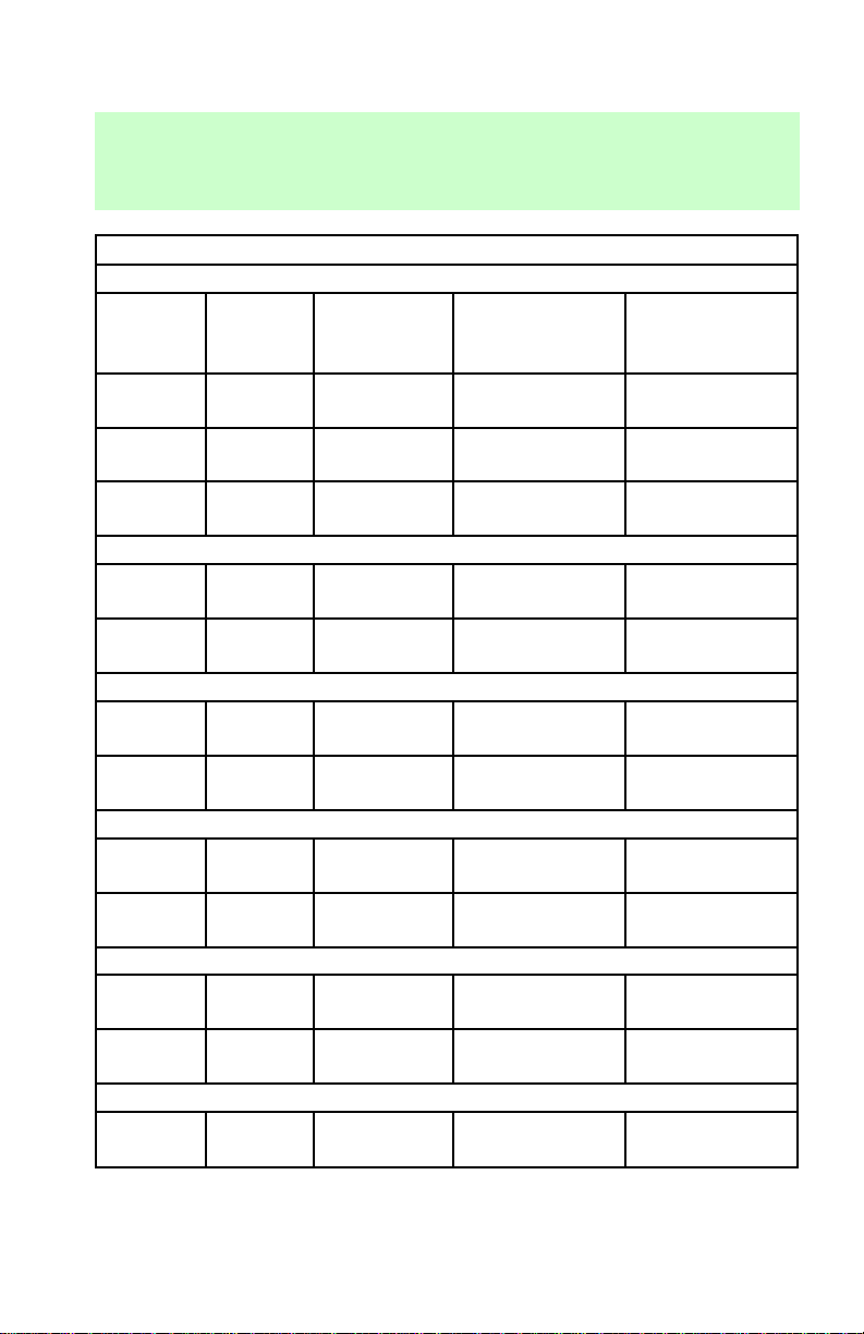
Driving
Trailer Towing Table
GCWR (Gross Combined Weight Rating)/Trailer Weights
Engine
Rear axle
4.6L 3.31
4.6L 3.55
5.4L 3.55
4.2L 3.73
5.4L 3.73
4.2L 4.09
5.4L 3.73
4.2L 3.73
5.4L 3.73
4.2L 4.09
5.4L 3.73
5.4L 3.55
ratio
Maximum
GCWR kg
(lb)
4,990
(11,000)
5,216
(11,500)
5,443
(12,000)
Regular Van E-250
4,763
(10,500)
5,897
(13,000)
Regular Van E-250 HD
4,990
(11,000)
5,897
(13,000)
Super Van E-250
4,763
(10,500)
5,897
(13,000)
Super Van E-250 HD
4,990
(11,000)
5,897
(13,000)
Regular Van E-350
5,443
(12,000)
Trailer weight
range kg (lb)
(0-Maximum)
2,766
(6,100)
2,993
(6,600)
3,130
(6,900)
2,359
(5,200)
3,402
(7,500)
2,586
(5,700)
3,402
(7,500)
2,313
(5,100)
3,357
(7,400)
2,540
(5,600)
3,356
(7,400)
2,948
(6,500)
Maximum
Frontal Area Of
Trailer Ft
2
60
60
60
60
60
60
60
60
60
60
60
60
90
Page 91
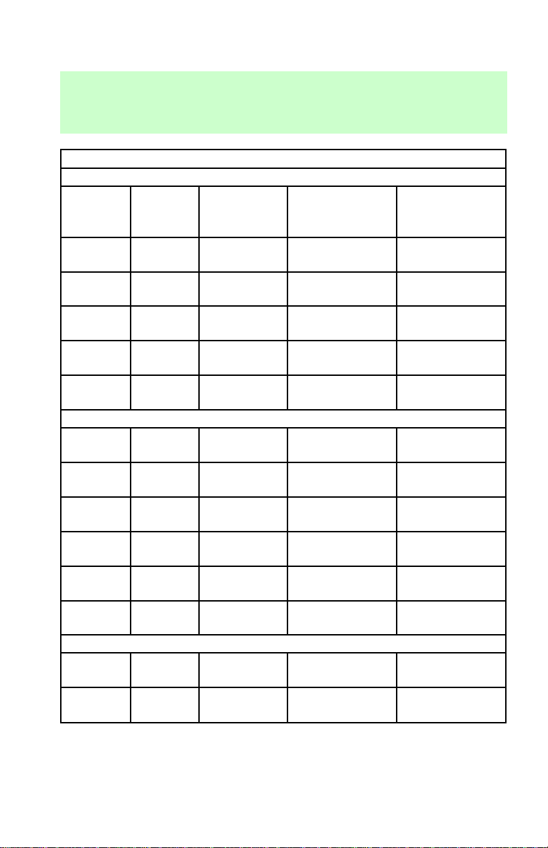
Trailer Towing Table
GCWR (Gross Combined Weight Rating)/Trailer Weights
Engine
Rear axle
5.4L 4.10
7.3L
(Diesel)
7.3L
(Diesel)
6.8L 3.73
6.8L 4.10
ratio
3.55
4.10
Maximum
GCWR kg
(lb)
5,897
(13,000)
7,258
(16,000)
9,072
(20,000)
6,804
(15,000)
8,392
(18,500)
Trailer weight
range kg (lb)
(0-Maximum)
3,402
(7,500)
4,536
(10,000)
4,536
(10,000)
4,218
(9,300)
4,536
(10,000)
Super Van E-350
5.4L 3.55
5.4L 4.10
7.3L
(Diesel)
7.3L
(Diesel)
6.8L 3.73
6.8L 4.10
3.55
4.10
5,443
(12,000)
5,897
(13,000)
7,258
(16,000)
9,072
(20,000)
6,804
(15,000)
8,392
(18,500)
2,858
(6,300)
3,311
(7,300)
4,445
(9,800)
4,536
(10,000)
4,173
(9,200)
4,536
(10,000)
Club Wagon E-150 (8 passenger)
4.2L 3.31
4.2L 3.55
4,082
(9,000)
4,536
(10,000)
1,678
(3,700)
2,132
(4,700)
Driving
Maximum
Frontal Area Of
Trailer Ft
2
60
60
60
60
60
60
60
60
60
60
60
60
60
91
Page 92
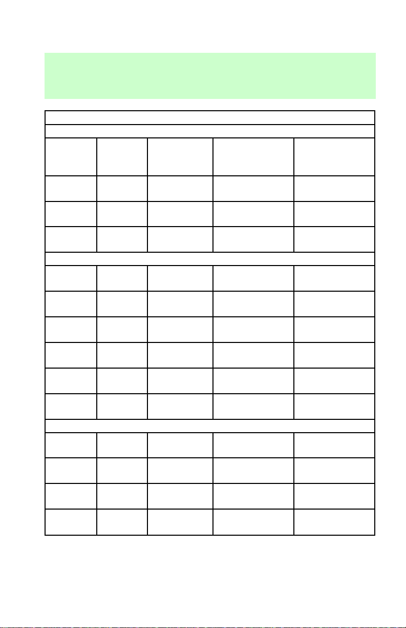
Driving
Trailer Towing Table
GCWR (Gross Combined Weight Rating)/Trailer Weights
Engine
Rear axle
4.6L 3.31
4.6L 3.55
5.4L 3.55
5.4L 3.55
5.4L 4.10
7.3L
(Diesel)
7.3L
(Diesel)
6.8L 3.73
6.8L 4.10
5.4L 3.55
5.4L 4.10
7.3L
(Diesel)
7.3L
(Diesel)
Maximum
ratio
GCWR kg
(lb)
4,990
(11,000)
5,216
(11,500)
5,443
(12,000)
Club Wagon Regular E-350 (12 passenger)
5,443
(12,000)
5,897
(13,000)
3.55
4.10
7,258
(16,000)
9,072
(20,000)
6,804
(15,000)
8,392
(18,500)
Club Wagon Super E-350 (15 passenger)
5,443
(12,000)
5,897
(13,000)
3.55
4.10
7,258
(16,000)
9,072
(20,000)
Trailer weight
range kg (lb)
(0-Maximum)
2,540
(5,600)
2,767
(6,100)
2,948
(6,500)
2,722
(6,000)
3,175
(7,000)
4,309
(9,500)
4,536
(10,000)
4,037
(8,900)
4,536
(10,000)
2,586
(5,700)
3,039
(6,700)
4,173
(9,200)
4,536
(10,000)
Maximum
Frontal Area Of
Trailer Ft
2
60
60
60
60
60
60
60
60
60
60
60
60
60
92
Page 93
Trailer Towing Table
GCWR (Gross Combined Weight Rating)/Trailer Weights
Engine
Rear axle
6.8L 3.73
6.8L 4.10
ratio
Maximum
GCWR kg
(lb)
6,804
(15,000)
8,392
(18,500)
Trailer weight
range kg (lb)
(0-Maximum)
3,901
(8,600)
4,536
(10,000)
E-350 RV Cutaway (single rear wheel)
7.3L
(Diesel)
4.10
9,072
(20,000)
4,717
(10,400)
E-350 RV Cutaway (dual rear wheel)
5.4L 4.10
6.8L 4.10
7.3L
(Diesel)
4.10
5,897
(13,000)
8,392
(18,500)
9,072
(20,000)
1,134
(2,500)
3,629
(8,000)
4,309
(9,500)
E-350 Commercial Cutaway (single rear wheel)
7.3L
(Diesel)
4.10
9,072
(20,000)
4,717
(10,400)
E-350 Commercial Cutaway (dual rear wheel)
5.4L 4.10
6.8L 4.10
7.3L
(Diesel)
4.10
5,897
(13,000)
8,392
(18,500)
9,072
(20,000)
1,225
(2,700)
3,720
(8,200)
4,400
(9,700)
E-Super Duty
6.8L 4.63
7.3L
(Diesel)
4.63
9,072
(20,000)
9,072
(20,000)
4,536
(10,000)
4,536
(10,000)
Driving
Maximum
Frontal Area Of
Trailer Ft
2
60
60
60
60
60
60
60
60
60
60
60
60
93
Page 94
Driving
Trailer Towing Table
GCWR (Gross Combined Weight Rating)/Trailer Weights
Maximum
GCWR kg
(lb)
Engine
Rear axle
ratio
E-250/350 Stripped Chassis (single rear wheel)
5.4L 4.10
6.8L 3.73
5,897
(13,000)
6,804
(15,000)
E-250/350 Stripped Chassis (dual rear wheel)
5.4L 4.10
6.8L 4.10
5,897
(13,000)
8,392
(18,500)
For high altitude operation, reduce GCWR by 2% per 300 meters
(1,000 ft) elevation.
To determine the maximum trailer weight designed for you particular
vehicle as equipped, follow the section Calculating the load your
vehicle can tow/carry earlier in this chapter.
TRAILER TOWING
Your vehicle may tow a class I, II
or III trailer provided the
maximum trailer weight is less
than or equal to the maximum
trailer weight listed for your engine
and rear axle ratio on the above
charts.
Your vehicle’s load capacity is
designated by weight, not by
volume, so you cannot necessarily
use all available space when
loading a vehicle.
Distribute the load so that only 10
to 15% of the total is on the
tongue. Tie down the load so that
Trailer weight
range kg (lb)
(0-Maximum)
1,542
(3,400)
2,540
(5,600)
1,361
(3,000)
3,856
(8,500)
Maximum
Frontal Area Of
Trailer Ft
60
60
60
60
2
94
Page 95

it does not shift and change the
weight on the hitch.
Towing a trailer places an
additional load on your vehicle’s
engine, transmission, axle, brakes,
tires and suspension. Inspect these
components carefully after any
towing operation.
Do not exceed the GVWR
or the GAWR specified on
the Safety Compliance
Certification Label.
Towing trailers beyond the
maximum recommended
gross trailer weight could result
in engine damage,
transmission/axle damage,
structural damage, loss of
control, and personal injury.
Preparing to tow
Use the proper equipment for
towing a trailer, and make sure it
is properly attached to your
vehicle. See your dealer or a
reliable trailer dealer if you require
assistance.
Hitches
Do not use or install hitches that
clamp onto the bumper or to the
axle. Underbody hitches are
acceptable if installed properly.
Step bumper (if equipped)
Step bumpers have a built-in hitch
and only require a ball with a 2.5
cm (1 in.) shank diameter. Step
Driving
95
Page 96

Driving
bumpers have a Class III capability
(2,270 kg [5,000 lb] trailer weight
and 227 kg [500 lb] tongue weight.
Safety chains
Always use safety chains between
your vehicle and trailer. Cross
chains under the trailer tongue and
allow slack for turning corners.
Connect safety chains to the
vehicle frame or hook retainers.
Never attach chains to the bumper.
Trailer brakes
Trailer brakes are required on
most towed vehicles weighing over
680 kg (1,500 lbs)
Do not connect a trailer’s
hydraulic brake system
directly to your vehicle’s brake
system. Your vehicle may not
have enough braking power and
your chances of having a
collision greatly increase.
Trailer lamps
Trailer lamps are required on most
towed vehicles. Make sure your
trailer lamps conform to Federal
and local regulations. See your
dealer or trailer rental agency for
the proper instructions and
equipment for hooking up trailer
lamps.
Driving while you tow
Do not drive faster than 88 km/h
(55 mph) while towing a trailer. Do
not drive faster than 72 km/h (45
mph) with a trailer while towing in
96
Page 97

hilly country or on hot days.
Speed control may shut off if you
are towing on very long, steep
grades.
When towing a trailer
If towing a trailer and your vehicle
is not equipped with the Ford
trailer tow package, an auxiliary
transmission fluid cooler is
recommended.
• Use D (Drive) rather than
D
(Overdrive) while towing up
or down steep hills. This will
eliminate excessive downshifting
and upshifting for optimum fuel
economy and transmission
cooling.
• Anticipate stops and brake
gradually.
• Allow more room for stopping
with a trailer attached.
• Practice turning, stopping and
backing in an area before
starting on a trip to get the feel
of the vehicle/trailer
combination.
• When turning, drive slightly
beyond the normal turning point
so the trailer wheels will clear
curbs and other obstacles.
• When stopped in traffic for long
periods of time in hot weather,
place the gearshift in P (Park)
to increase idle speed. This aids
engine cooling and air
conditioner efficiency.
• Vehicles with trailers should not
be parked on a grade. If you
Driving
97
Page 98

Driving
must park on a grade, place
wheel chocks under the trailer’s
wheels.
• After you have travelled about
80 km (50 miles), thoroughly
check your hitch, electrical
connections and trailer wheel
lug nuts.
Launching or retrieving a boat
When backing down a ramp during
boat launching or retrieval,
• Do not allow the static water
level to rise above the bottom
edge of the rear bumper and
• Do not allow waves to break
higher than 15 cm (six inches)
above the bottom edge of the
rear bumper.
Exceeding these limits may allow
water to enter critical vehicle
components, adversely affecting
driveability, emissions and
reliability.
Servicing when towing
If you tow a trailer for long
distances, your vehicle will require
more frequent service intervals.
Follow the severe duty
maintenance schedule outlined in
the “Service Guide.”
98
Page 99

FUEL CONSUMPTION
Fuel economy can be improved by
avoiding:
• lack of regular, scheduled
maintenance
• excessive speed
• rapid acceleration
Driving
99
Page 100
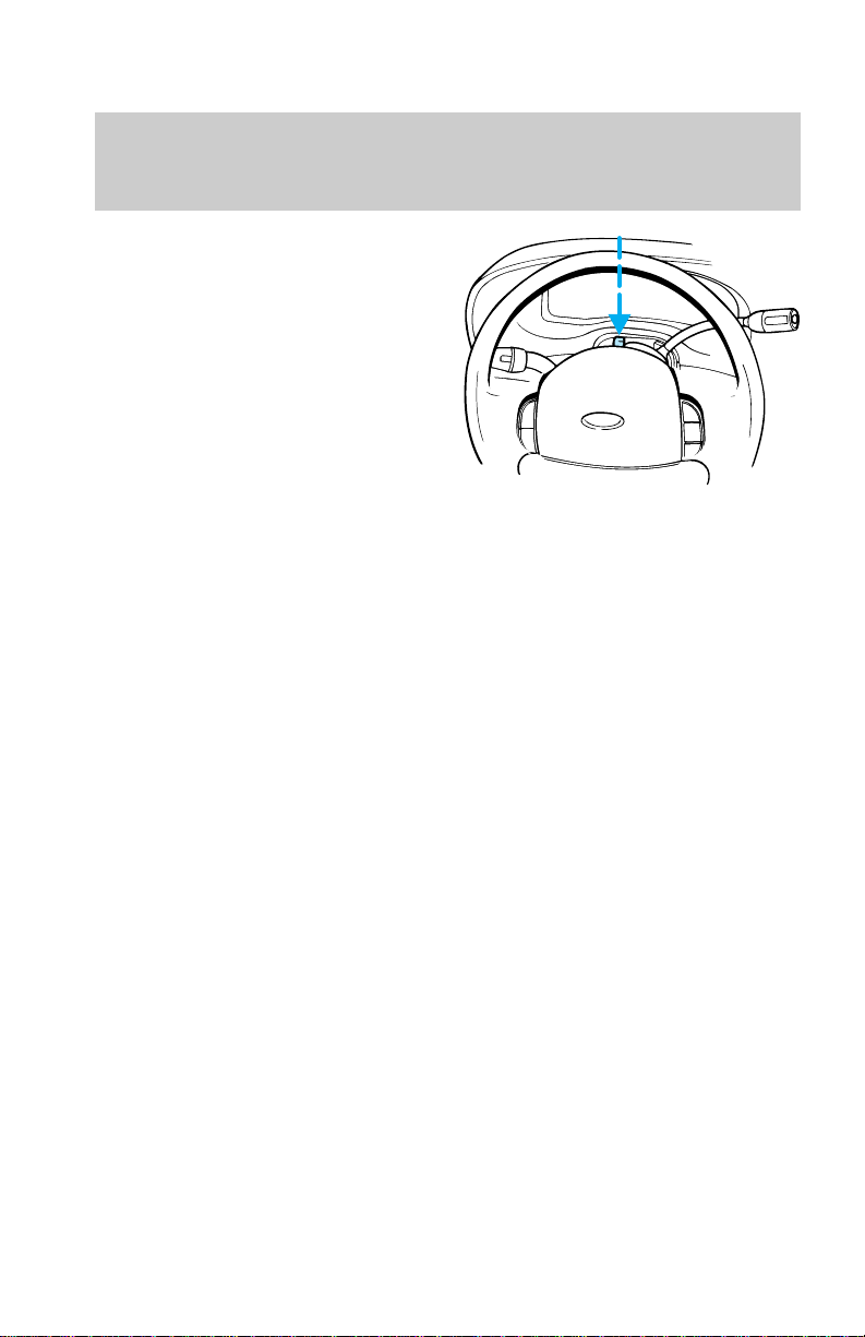
Roadside emergencies
HAZARD LIGHTS CONTROL
Use only in an emergency to warn
traffic of vehicle breakdown,
approaching danger, etc. Depress
to activate all indicators
simultaneously. Depress again to
switch off. The warning lights can
be operated when the ignition is
off.
FUEL PUMP SHUT-OFF SWITCH
If the engine cranks but does not
start after a collision, the fuel
pump shut–off switch may have
been activated. The shut–off
switch is a device intended to stop
the electric fuel pump when your
vehicle has been involved in a
substantial jolt.
1. Turn the ignition switch to the
OFF position.
2. Check fuel system for leaks.
100
 Loading...