

Page 1

2016 Explorer Vehicle Security/Remote Start/Remote Access
Vehicle Security / Remote Start / Remote Access
System Installation
CONTENTS
VEHICLE PREPARATION
Hood Switch Installation
*+,"",*-+
VSS Module Installation
Security Indicator LED Mounting
RMST Kit Antenna Installation
RMU Module Installation
GENERAL PROCEDURES
Learn VSS to vehicle
Shock Sensor Sensitivity Adjustment
Standard Remote Start Activation
RMU Remote Start Activation
RMU Activation
Proper Wire Splicing Techniques
Contents SK9L2J-19G364-AA
© Copyright Ford 2015 FoMoCo
Page 2
INSTALLATION
2016 Explorer
Vehicle Security/Remote Start/Remote Access
1
Page 1 of 27
SK9L2J-19G364-AA
© Copyright Ford 2016 FoMoCo
Vehicle Security / Remote Start / Remote Access - Explorer
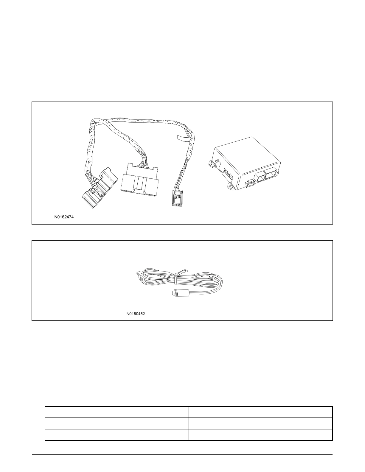
VSS System Components
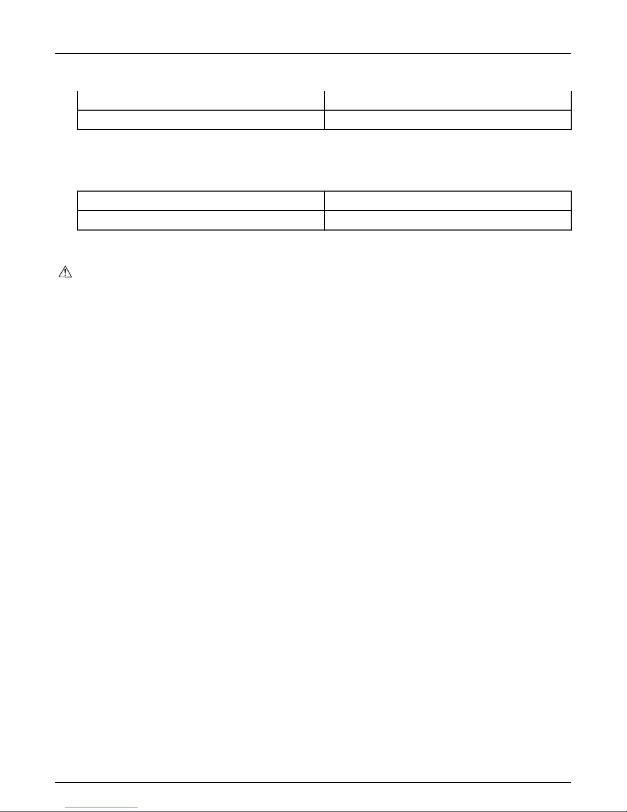
Security Indicator LED (19D596) "Optional"
Explorer
1. Verify correct kit number.
Review VSS Kit Contents
NOTE:
Kits are vehicle specific and are not interchangeable.
2. Review the VSS kit contents.
Vehicle Security System (VSS) Kit
QUANTITY DESCRIPTION
1 VSS Module
1 T-harness
Page 3
INSTALLATION (Continued)
2016 Explorer
Vehicle Security/Remote Start/Remote Access
2
Page 2 of 27
SK9L2J-19G364-AA
© Copyright Ford 2016 FoMoCo
Vehicle Security System (VSS) Kit(Continued)
6 Tie-straps
1 Owner's Manual
Security Indicator LED Kit Contents "Optional"
3. Review the Security Indicator LED kit contents.
Security Indicator LED Kit
QUANTITY DESCRIPTION
1 Security Indicator LED
I. VSS System Installation
CAUTION:
Carefully route and secure module and harnesses so that they do not interfere with moving parts
or linkages.
NOTE:
If the VSS kit was installed previously and the vehicle is being upgraded, proceed to the "RMST" or
"RMU" upgrade section(s).
NOTE:
If the hood switch is not installed, complete the Hood Switch Kit installation.
4. If the vehicle is equipped with factory remote start, test its operation by pressing the Lock button
one time and the Remote Start button two times.
• If the vehicle remote starts, stop the engine by pressing the Remote Start button one time.
• If the vehicle does not remote start, diagnose the concern.
5. Disconnect the vehicle battery negative terminal. For additional information, refer to Workshop
Manual (WSM) Section 414-01.
6. Remove the LH lower IP insulator.
Page 4
INSTALLATION (Continued)
2016 Explorer
Vehicle Security/Remote Start/Remote Access
3
Page 3 of 27
SK9L2J-19G364-AA
© Copyright Ford 2016 FoMoCo
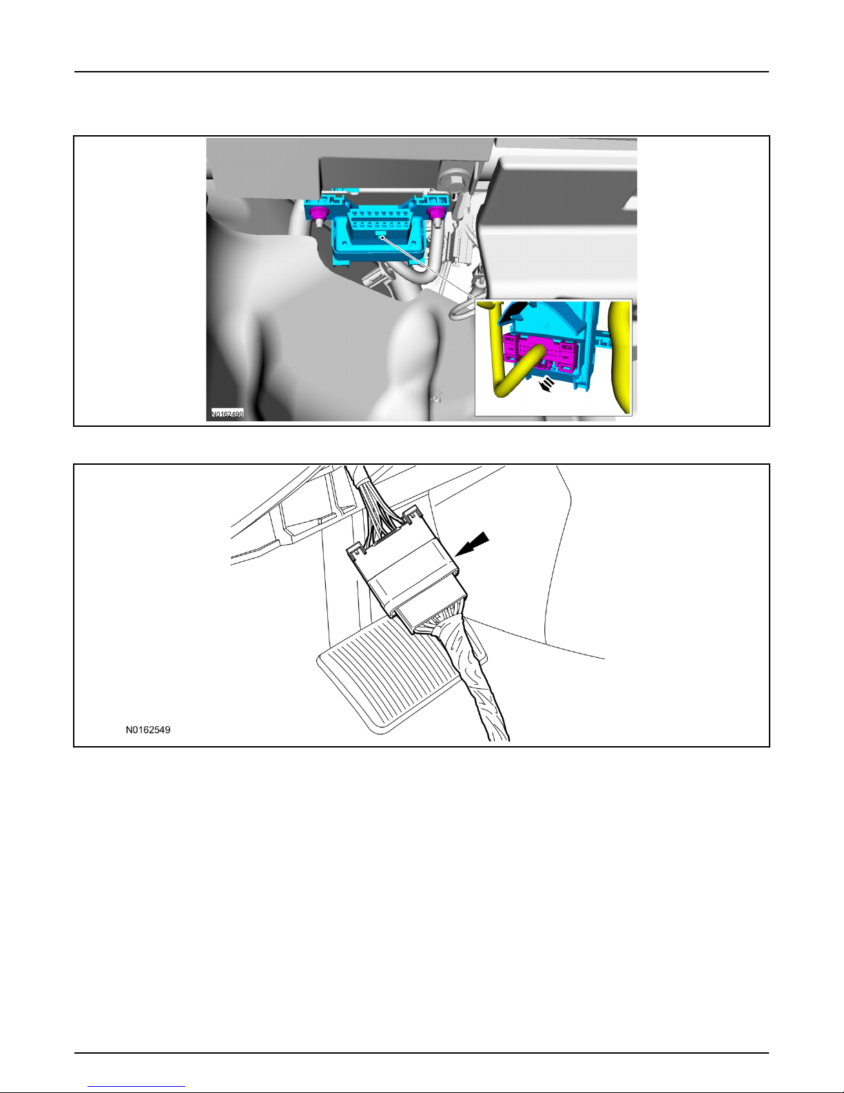
7. Disconnect the electrical connector from the back of the gateway module.
8. Connect the VSS T-harness to the gateway module electrical connector.
Page 5

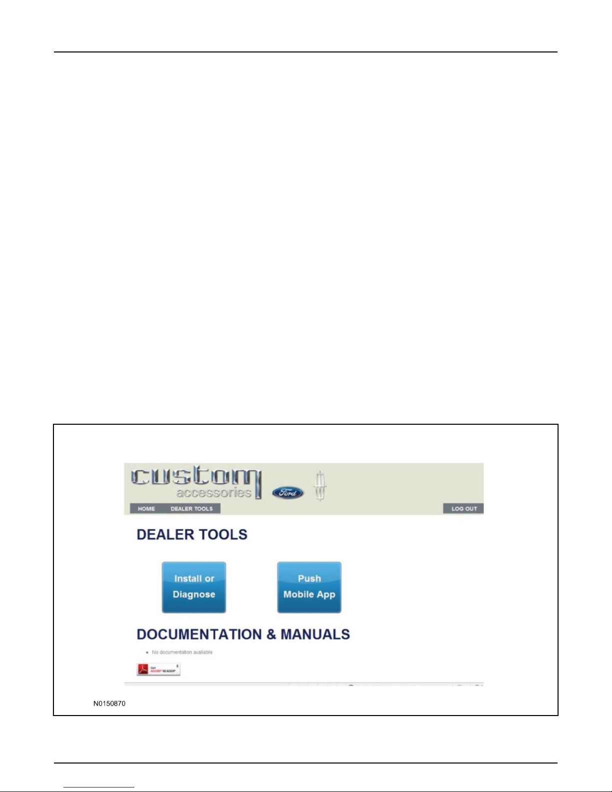
INSTALLATION (Continued)
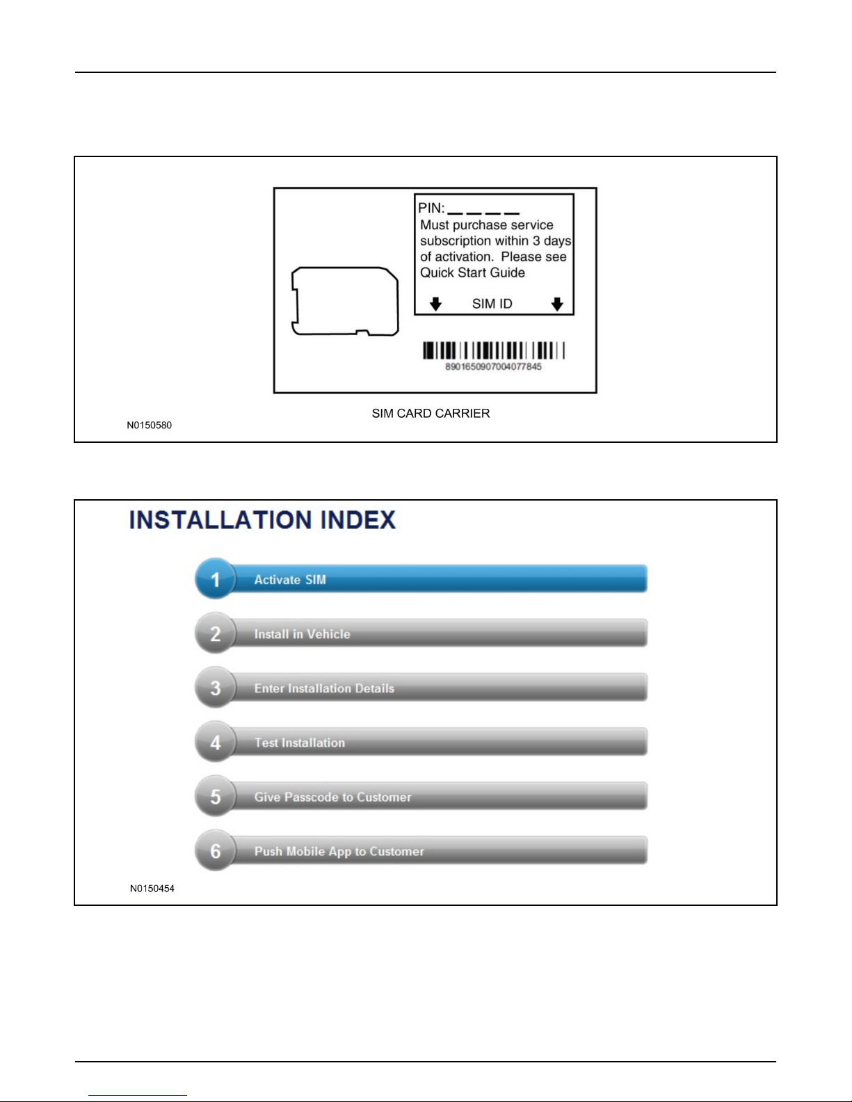
2016 Explorer
Vehicle Security/Remote Start/Remote Access
4
Page 4 of 27
SK9L2J-19G364-AA
© Copyright Ford 2016 FoMoCo
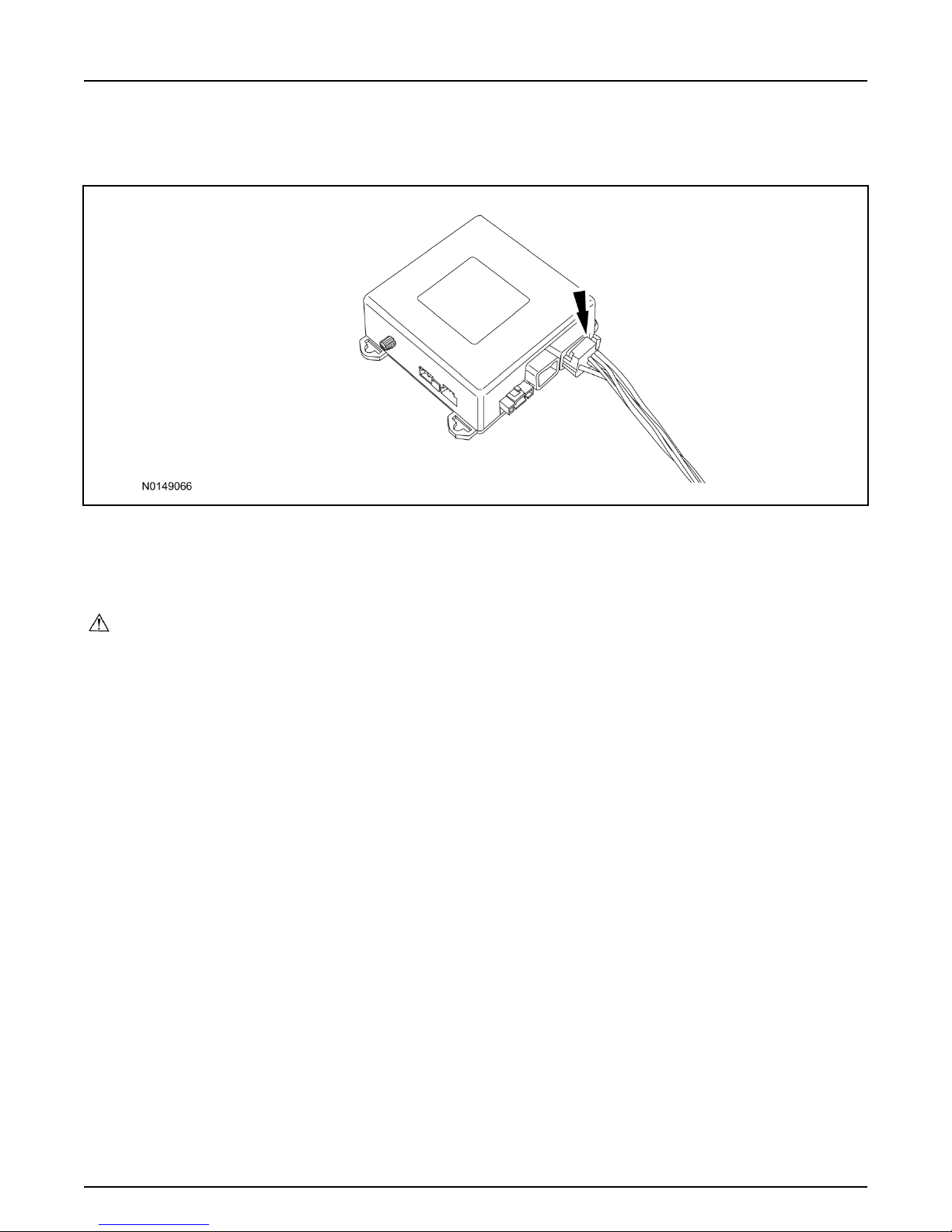
9. Connect the VSS T-harness to the back of the gateway module.
10. Position the T-harness inside the IP being careful to avoid sharp edges and moving parts.
• Secure with zip-ties.
11. Position the VSS module behind the BCM (Body Control Module) and secure it to a wire harness
with tie-straps.
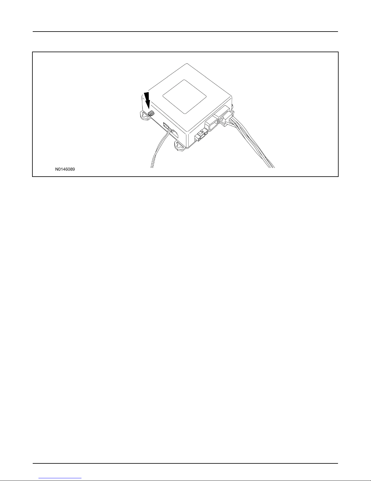
• Ensure the VSS module is positioned so the shock sensor adjustment knob can be accessed for
later use.
• Ensure the tie-strap is routed through the VSS module loops at opposite corners.
Page 6
INSTALLATION (Continued)
2016 Explorer
Vehicle Security/Remote Start/Remote Access
5
Page 5 of 27
SK9L2J-19G364-AA
© Copyright Ford 2016 FoMoCo
12. Connect the VSS harness to the VSS module.
• Secure the VSS harness with tie-straps.
13. Connect the vehicle battery negative terminal. For additional information, refer to WSM Section
414-01.
Optional Security Indicator LED Mounting
CAUTION:
Carefully route and secure module and harnesses so that they do not interfere with moving parts
or linkages.
14. Keep the following points in mind when routing or positioning the LED for mounting:
• Have at least 3/4" clearance behind trim panels for the wiring harness to be routed.
• The LED should be clearly visible from the driver's side window when mounted.
• Do not mount the LED on trim panels that cover air bags.
15. Mount the LED at an appropriate location on the upper steering column shroud, using the guidelines
listed above.
• Drill a 9/32" hole into the selected location, for the LED to mount in.
16. Route the LED wire harness to the VSS module.
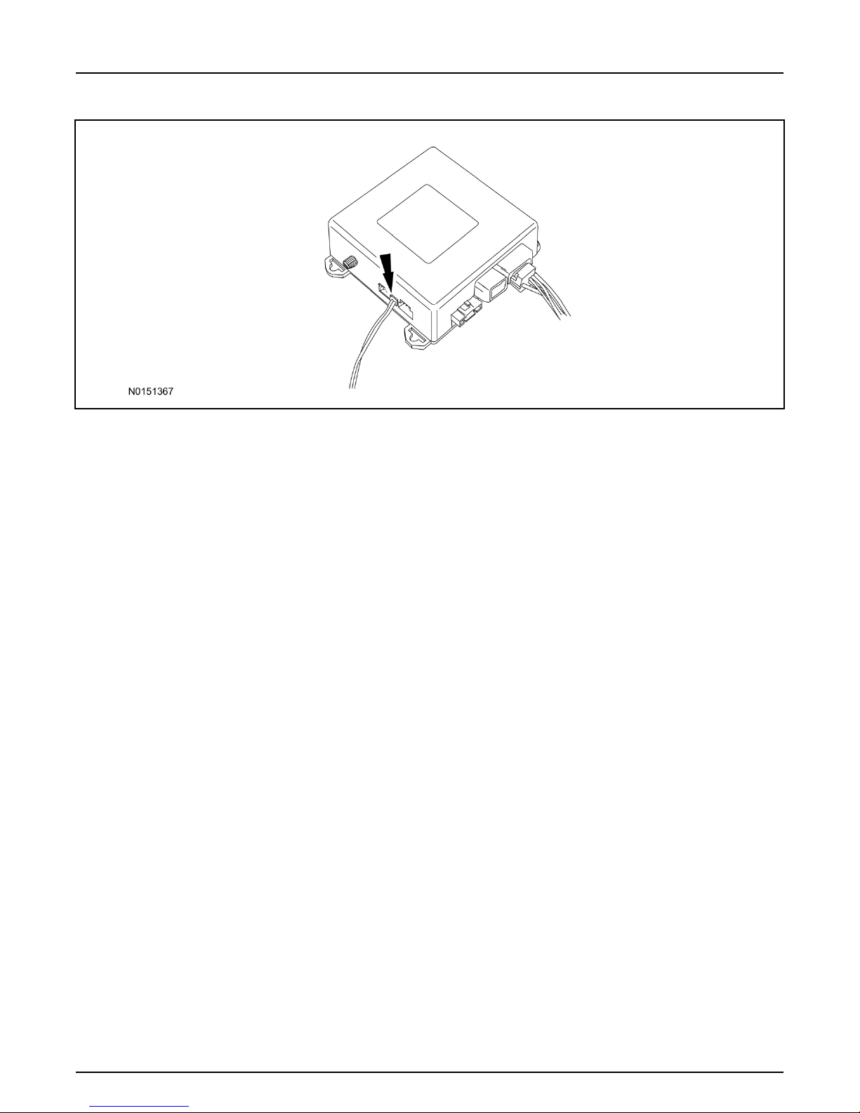
17. Connect the LED wire harness to the VSS module 2-pin white connector.
• Secure the LED wire harness with tie-straps.
Page 7
INSTALLATION (Continued)
2016 Explorer
Vehicle Security/Remote Start/Remote Access
6
Page 6 of 27
SK9L2J-19G364-AA
© Copyright Ford 2016 FoMoCo
Perimeter Alarm Activation - Vehicles Without Factory Installed Perimeter Alarm
18. Verify that the IDS is updated to the most current version.
19. Connect IDS.
• Follow the prompts to select new vehicle session.
•
Enter VIN.
20. Activate the perimeter alarm using the IDS.
• Select the Tool Box icon.
• Select Body.
• Select Security.
• Select Perimeter Alarm.
• Verify that the information on the IDS screen is correct and all procedures have been followed.
• Select Yes. This will enable the perimeter alarm function on the vehicle.
Page 8

INSTALLATION (Continued)
2016 Explorer
Vehicle Security/Remote Start/Remote Access
7
Page 7 of 27
SK9L2J-19G364-AA
© Copyright Ford 2016 FoMoCo
Learn VSS to Vehicle (Key Start Vehicles Only)
21. Cycle ignition OFF, ON, OFF one time to learn VSS to the vehicle.
22. Use IDS to clear continuous DTCs.
23. If the vehicle is equipped with factory remote start, test its operation by pressing the Lock button
one time and the Remote Start button two times.
• If the vehicle remote starts, stop the engine by pressing the Remote Start button one time.
•
If the vehicle does not remote start, disconnect the vehicle battery negative terminal, wait five
minutes and then reconnect the battery negative terminal. For additional information, refer to
Workshop Manual (WSM) Section 414-01.
• Retest the factory remote start.
• If the vehicle does not remote start, diagnose the concern.
Shock Sensor Sensitivity Adjustment
NOTE:
The VSS module is equipped with an internal dual zone Shock Sensor. The VSS system will activate a
single horn honk/single light flash anytime a light to moderate impact is detected, and a "panic" type 30
second horn honk/light flash sequence when a heavy impact is detected while the VSS system is armed.
Adjustment of both zones is accomplished through a single adjustment knob on the VSS module.
Rotating the knob clockwise will increase sensitivity and rotating the knob counter-clockwise will
decrease sensitivity. Sensitivity adjustment must be completed with the module securely mounted and
the adjustment knob accessible.
Page 9
INSTALLATION (Continued)
2016 Explorer
Vehicle Security/Remote Start/Remote Access
8
Page 8 of 27
SK9L2J-19G364-AA
© Copyright Ford 2016 FoMoCo
24. Starting with the adjustment knob in approximately the halfway position, lower the driver's window
and exit the vehicle.
25. Press the LOCK button on the vehicle's RKE fob to arm the VSS system. The LED will light solid
for 20 seconds and then begin to flash a steady on/off sequence to indicate the system is armed.
26. Using a closed fist, impact the steering wheel with moderate force to simulate a light impact on the
vehicle. If the impact is detected, the horn will honk and the lights will flash 1 time to indicate the
warning impact was detected.
27. Using a closed fist, impact the steering wheel with heavy force to simulate a hard impact (i.e. glass
breakage) on the vehicle. If the impact is detected, the horn will honk and the lights will flash a
steady on off sequence to indicate the heavy or full shock trigger was detected.
28. Increase (rotate clockwise) or decrease (rotate counter-clockwise) the adjustment knob as necessary
to achieve desired sensitivity, repeat the previous steps to test, and verify adjustment.
VSS Functional Test
NOTE:
If installed, observe the LED while performing these tests.
NOTE:
Cycle ignition OFF, ON, OFF before testing.
29.
Lower the driver's door window, then close all doors, hood, and trunk/hatch and press lock on the
keyfob. The LED should stay lit for 20 seconds while the VSS system pre-arms, after which it will
flash every 3-4 seconds in fully armed mode.
30. Reach inside the window and use the inside driver's door handle to open the door. The LED should
continue to flash, indicating that the vehicle is still armed. The alarm should sound, indicating
perimeter breach. Turn the alarm off by turning the ignition to "On".
• If equipped with OE perimeter security, there will be a 12 second interior chime prior to alarm
sounding. For vehicles not equipped with OE perimeter security, there will be a 12 second delay
with no interior chime prior to alarm sounding.
Page 10
INSTALLATION (Continued)
2016 Explorer
Vehicle Security/Remote Start/Remote Access
9
Page 9 of 27
SK9L2J-19G364-AA
© Copyright Ford 2016 FoMoCo
• For push button start vehicles, the Intelligent Access (IA) key must be away from the vehicle,
otherwise the security system may disarm immediately upon trigger.
31. Exit the vehicle and arm it again, this time leaving the driver's door open. The vehicle should arm
itself, ignoring the open door but monitoring the rest. Once the vehicle is armed, shut the driver's
door and reopen it after a few seconds. The alarm should sound. Turn the alarm off by hitting
unlock on the keyfob.
• For push button start vehicles, the Intelligent Access (IA) key must be away from the vehicle,
otherwise the security system may disarm immediately upon trigger.
32. Test all other vehicle doors, the hood and the trunk in the same manner, by setting off the alarm and
disarming with the keyfob.
33. If the VSS kit will not be upgraded to RMST/RMU functions at this time, install the LH lower IP
insulator.Please contact 1-800-FORD-KEY with any issues regarding hardware or kit
contents.
II. Remote Start (RMST) Upgrade - Antenna Kit "Sold Separately"
CAUTION:
Carefully route and secure module and harnesses so that they do not interfere with moving parts
or linkages.
NOTE:
Verify that the vehicle has a hood switch Installed. If the vehicle is not equipped with a hood switch
refer to "Hood Switch Kit - Sold Separately".
Page 11
INSTALLATION (Continued)
2016 Explorer
Vehicle Security/Remote Start/Remote Access
10
Page 10 of 27
SK9L2J-19G364-AA
© Copyright Ford 2016 FoMoCo
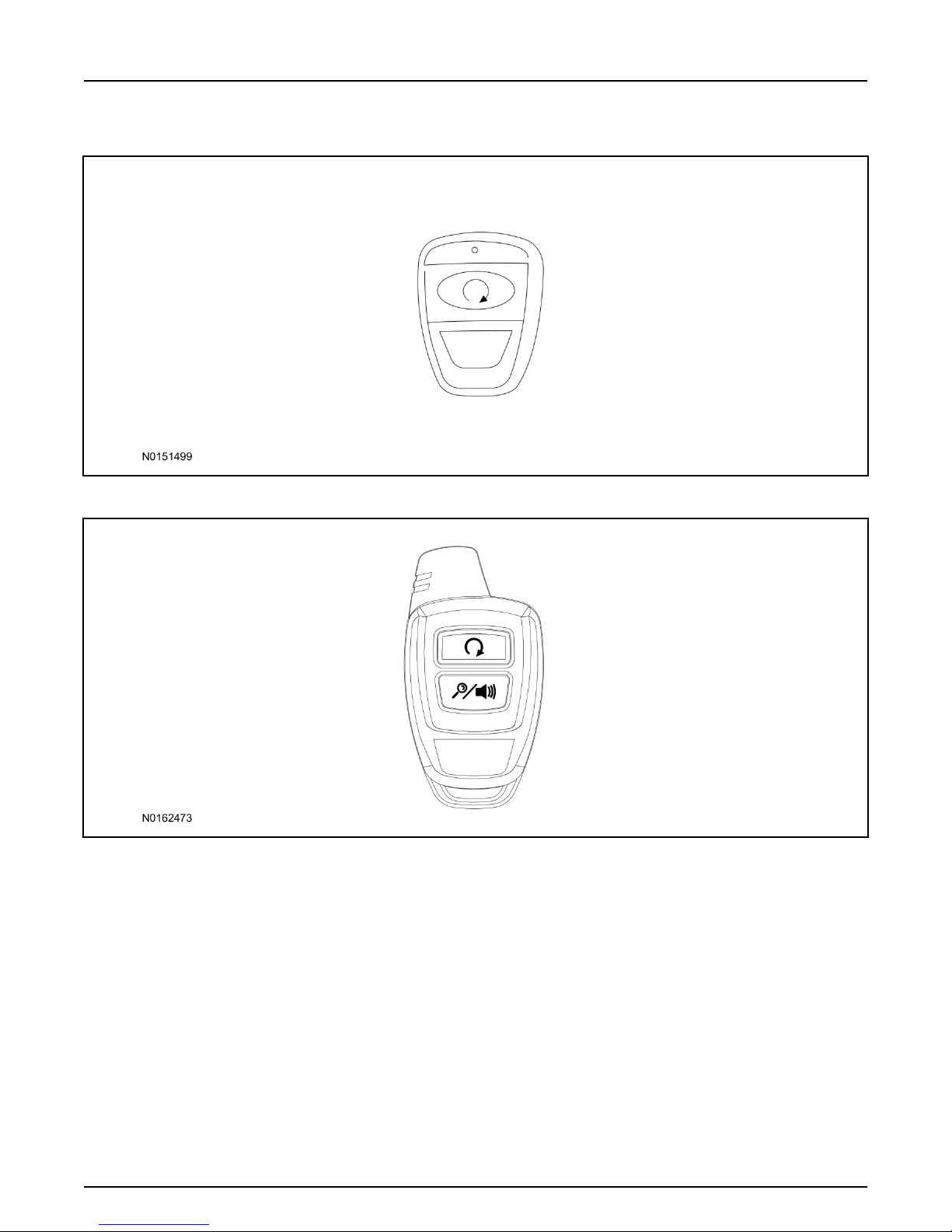
Standard Key Fob (15K601) "Sold Separately"
Bi-directional Key Fob (15K601) "Sold Separately"
Page 12
INSTALLATION (Continued)
2016 Explorer
Vehicle Security/Remote Start/Remote Access
11
Page 11 of 27
SK9L2J-19G364-AA
© Copyright Ford 2016 FoMoCo
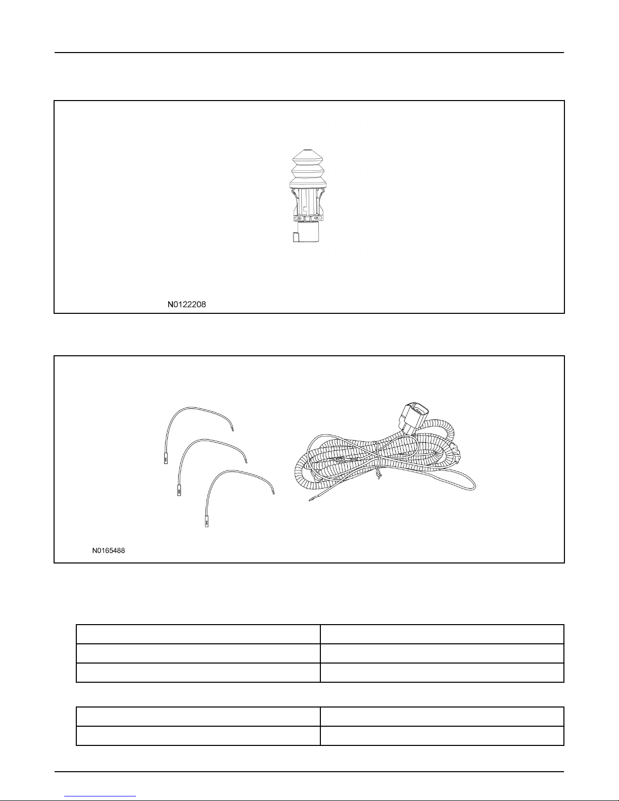
Hood Switch Kit (19G366) - Base Vehicles Only "Sold Separately"
Optional Components - Hood Switch Wire Harness Kit (14B504) - Base Vehicles Only
"Sold Separately"
Optional RMST Upgrade Components "Sold Separately"
34. Review the RMST Upgrade components.
Remote Start (RMST) Upgrade - Antenna Kit (15603) "Sold Separately"
QUANTITY DESCRIPTION
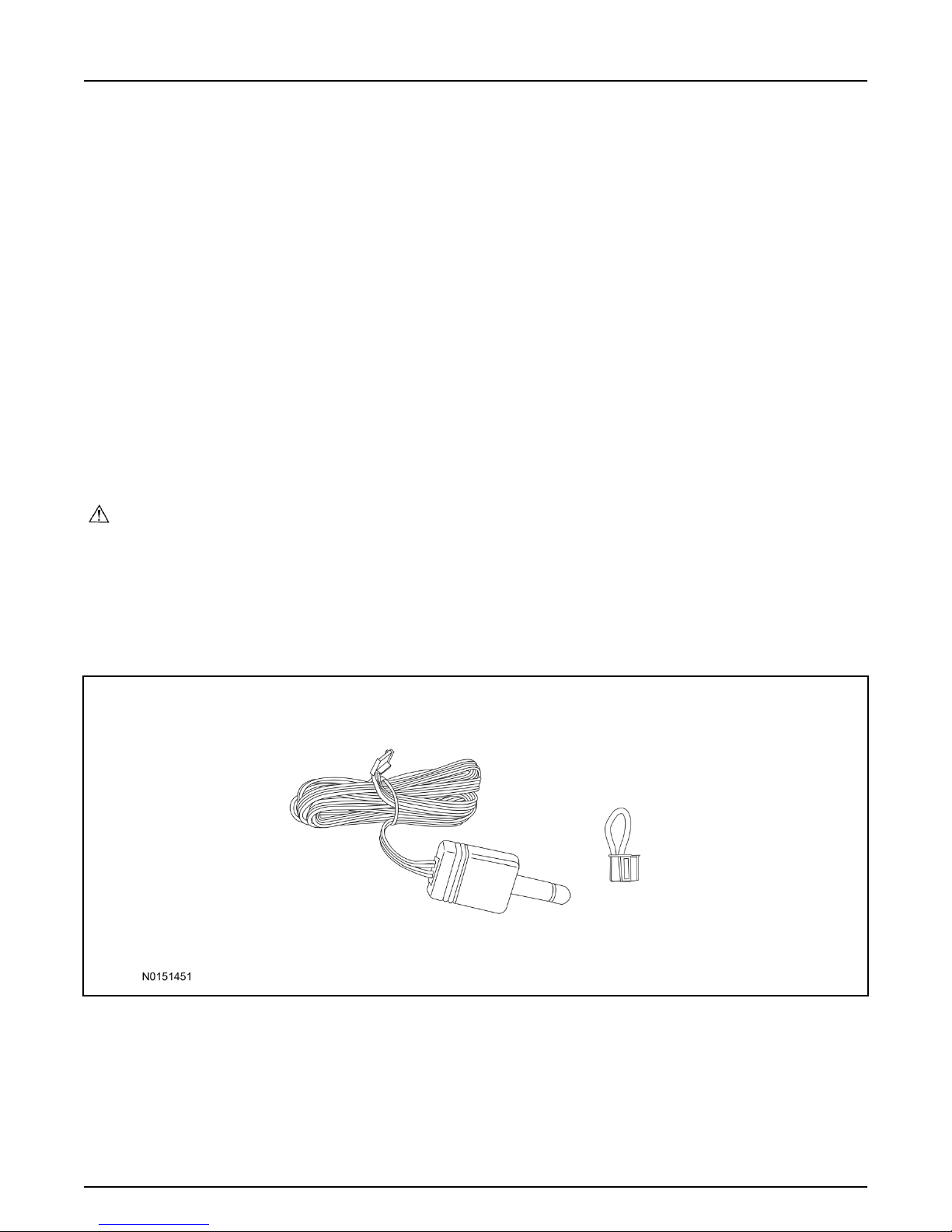
1 Bi-directional Antenna
1 Security Jumper
Standard Key Fob (15K601) "Sold Separately"
QUANTITY DESCRIPTION
1 Standard Key Fob (15K601)
Page 13
INSTALLATION (Continued)
2016 Explorer
Vehicle Security/Remote Start/Remote Access
12
Page 12 of 27
SK9L2J-19G364-AA
© Copyright Ford 2016 FoMoCo
Bi-directional Key Fob (15K601) "Sold Separately"
QUANTITY DESCRIPTION
1 Bi-directional Key Fob (15K601)
Hood Switch Kit Contents (if required) "Sold Separately"
35. Review the Hood Switch kit contents.
Hood Switch Kit "Sold Separately"
QUANTITY DESCRIPTION
1 Hood Switch Assembly
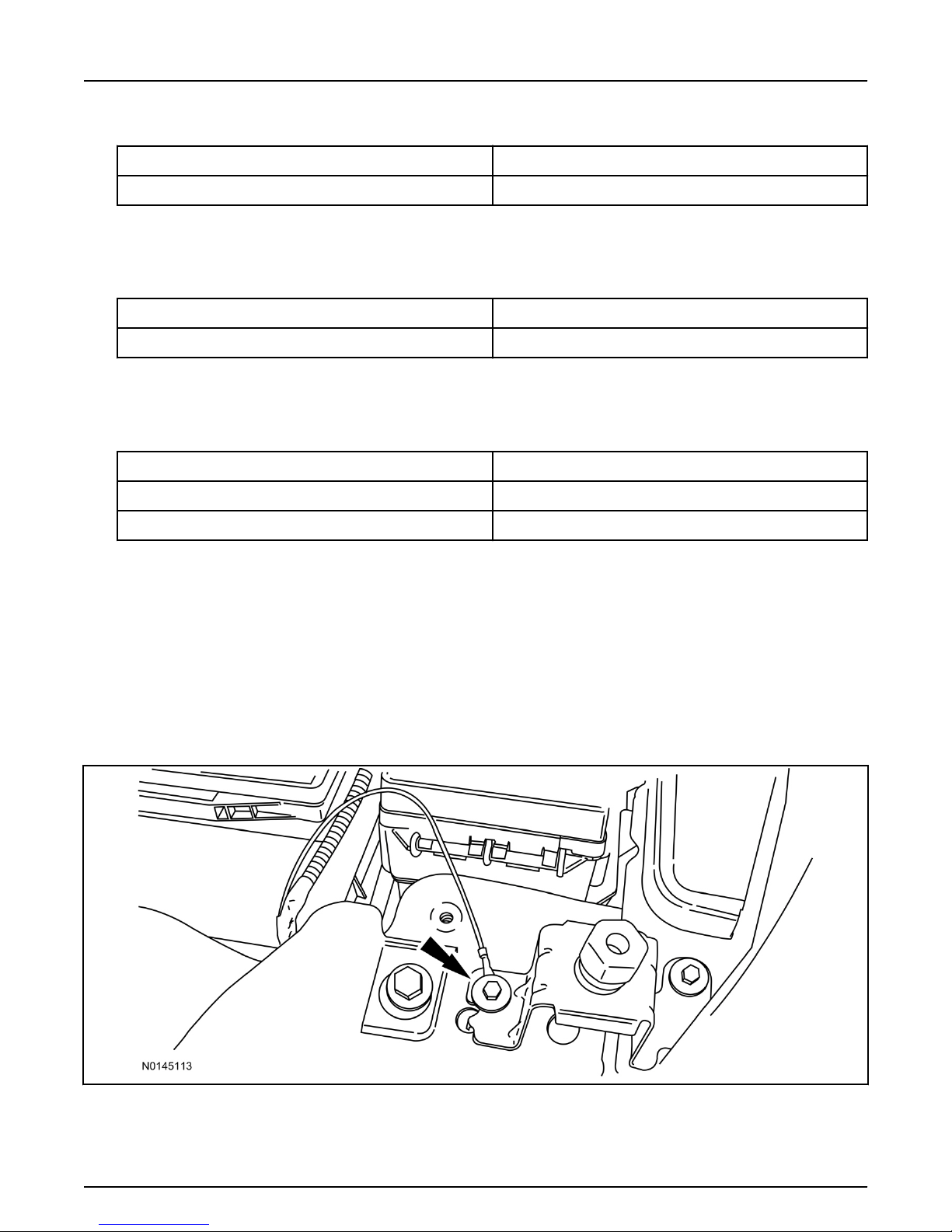
Review Hood Switch Wire Harness Kit Contents (if required) "Sold Separately"
36. Review the Hood Switch kit contents.
Hood Switch Wire Harness Kit "Sold Separately"
QUANTITY DESCRIPTION
3 Body Control Module (BCM) Terminal Wire
1 Hood Switch Wire Harness
Hood Switch Kit - "Sold Separately"
NOTE:
Hood switch installation is required for VSS/RMST/RMU installation if the vehicle is not currently
equipped with a hood switch.
37. If previously installed, remove the LH lower IP insulator.
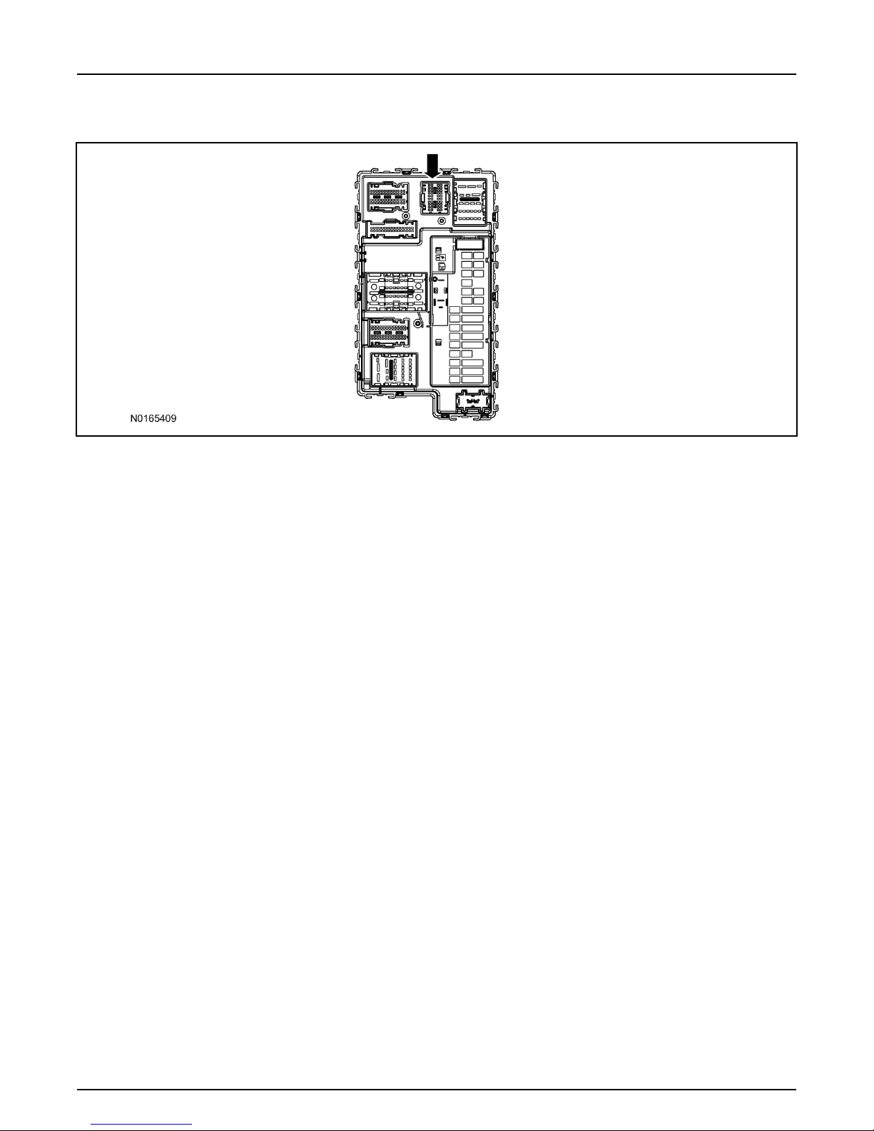
38. Remove the fender bolt and install the hood switch ground wire, using the previously removed bolt.
• Tighten to 12 Nm (106 lb-in).
39. Route the hood switch wire harness into the vehicle through the bulkhead grommet.
• Secure the hood switch wire harness with zip-ties.
Page 14
INSTALLATION (Continued)
2016 Explorer
Vehicle Security/Remote Start/Remote Access
13
Page 13 of 27
SK9L2J-19G364-AA
© Copyright Ford 2016 FoMoCo
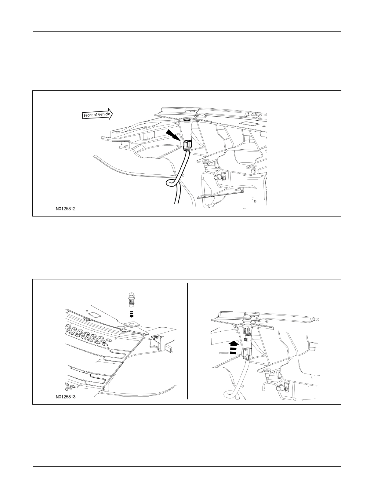
40. Disconnect Body Control Module (BCM) connector C2280F.
41. If equipped, remove the pin plug from BCM connector C2280F Pin 14.
•
If the vehicle is not equipped with a hood switch wire harness from the factory C2280F will not
have a wire at the Pin 14 location.
42. NOTICE:
Check that the all wire pins are attached firmly and properly positioned/secured within the
connector shell, after performing this step.
NOTE:
Use terminal wire labeled #3 (Orange).
Insert the BCM terminal wire from the hood switch wire harness kit into BCM connector C2280F
Pin 14.
Some disassembly of BCM connector C2280F may be required to perform this step.
•
43.
Connect BCM connector C2280F.
NOTICE:
Refer to "Proper Wire Splicing Techniques" before proceeding.
Connect the hood switch wire harness wire to the BCM Terminal Wire.
44.
•
Secure the wire harness assembly with zip-ties.
Page 15
INSTALLATION (Continued)
2016 Explorer
Vehicle Security/Remote Start/Remote Access
14
Page 14 of 27
SK9L2J-19G364-AA
© Copyright Ford 2016 FoMoCo
45. Locate the vehicle's existing "OE" hood switch wire harness, located on the LH side of the vehicle
below the radiator core support.
• If required remove the vehicle's air cleaner assembly, to access the vehicles "OE" hood switch
wire harness. For additional information, refer to WSM, Section 303-12.
46. Install the OE hood switch assembly to the existing hood switch mounting location, on the LH side
of the upper radiator core support as shown.
• If equipped, remove the dummy plug from the upper radiator core support.
• Position the flat spot on the hood switch to the flat spot on the radiator core support.
• Connect the electrical connector to the hood switch.
Page 16
INSTALLATION (Continued)
2016 Explorer
Vehicle Security/Remote Start/Remote Access
15
Page 15 of 27
SK9L2J-19G364-AA
© Copyright Ford 2016 FoMoCo
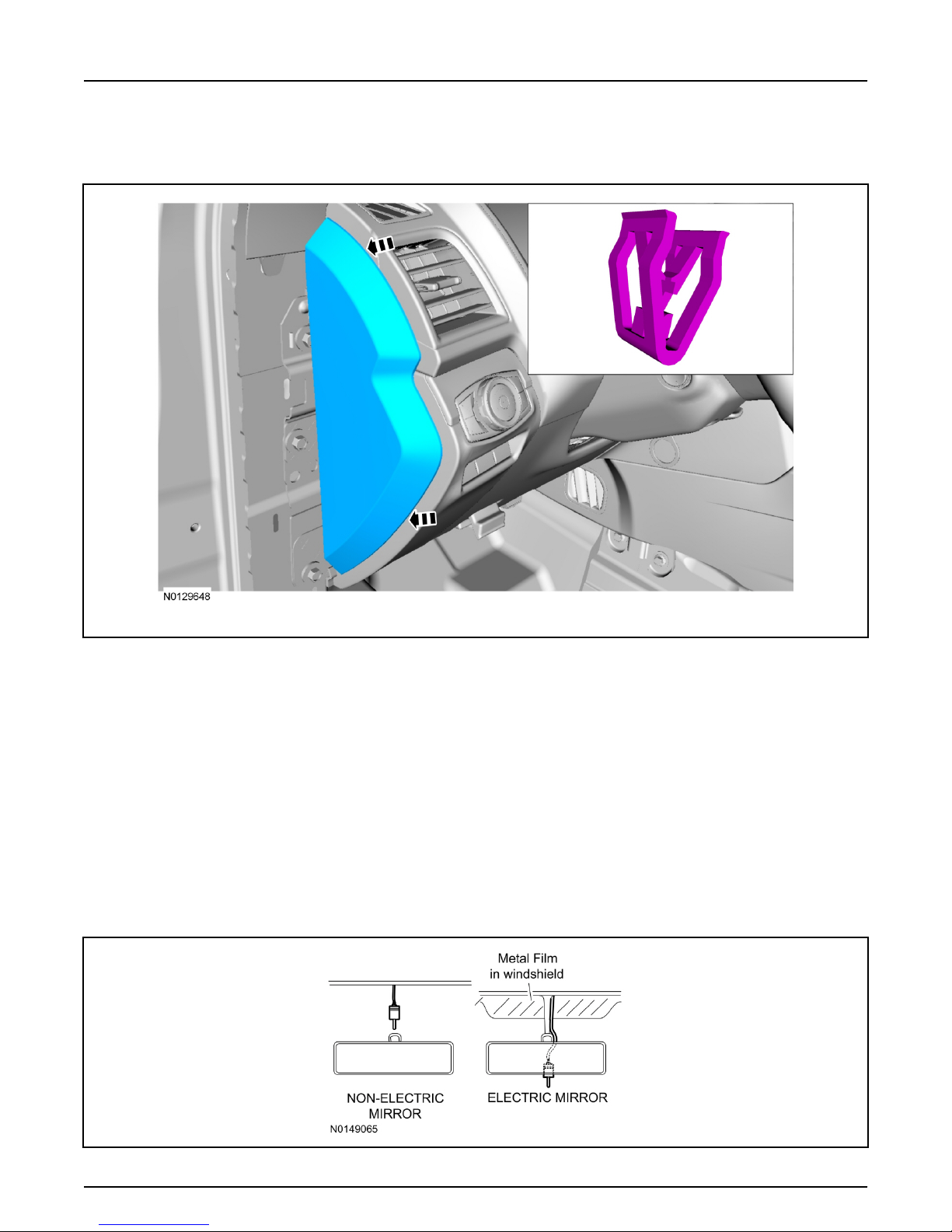
RMST Kit Antenna Installation
47. Remove the LH IP side finish panel.
48. Clean the antenna mounting surface using an alcohol base solution and a clean cloth.
49. NOTE:
Do not touch the adhesive, reduced adhesion may result.
NOTE:
Make sure that the long wire on the antenna is pointing towards the top of the windshield since this
wire will be routed along the headliner.
NOTE:
The wire will be attached to the control module later in this procedure.
Remove the protective backing from the adhesive on the antenna and firmly press the body of the
antenna onto the mounting surface.
Page 17
INSTALLATION (Continued)
2016 Explorer
Vehicle Security/Remote Start/Remote Access
16
Page 16 of 27
SK9L2J-19G364-AA
© Copyright Ford 2016 FoMoCo
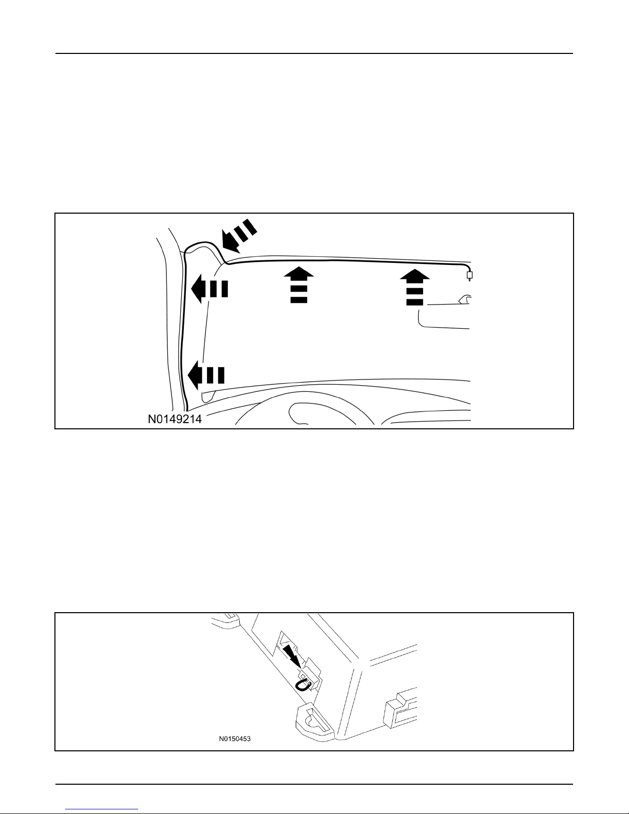
50. If necessary, position the LH A-pillar trim slightly outward to provide access to route the antenna
wire.
NOTE:
Do not route the antenna wire over the top of air bags.
51. Route the antenna cable along the headliner and down the LH A-pillar towards the floor. Continue
routing the wire Into the IP towards the VSS module.
• Secure with tie-straps.
52. Connect the antenna connector to the VSS module.
53. Reposition the A-pillar trim panel back, if necessary.
54. Install the LH IP side finish panel.
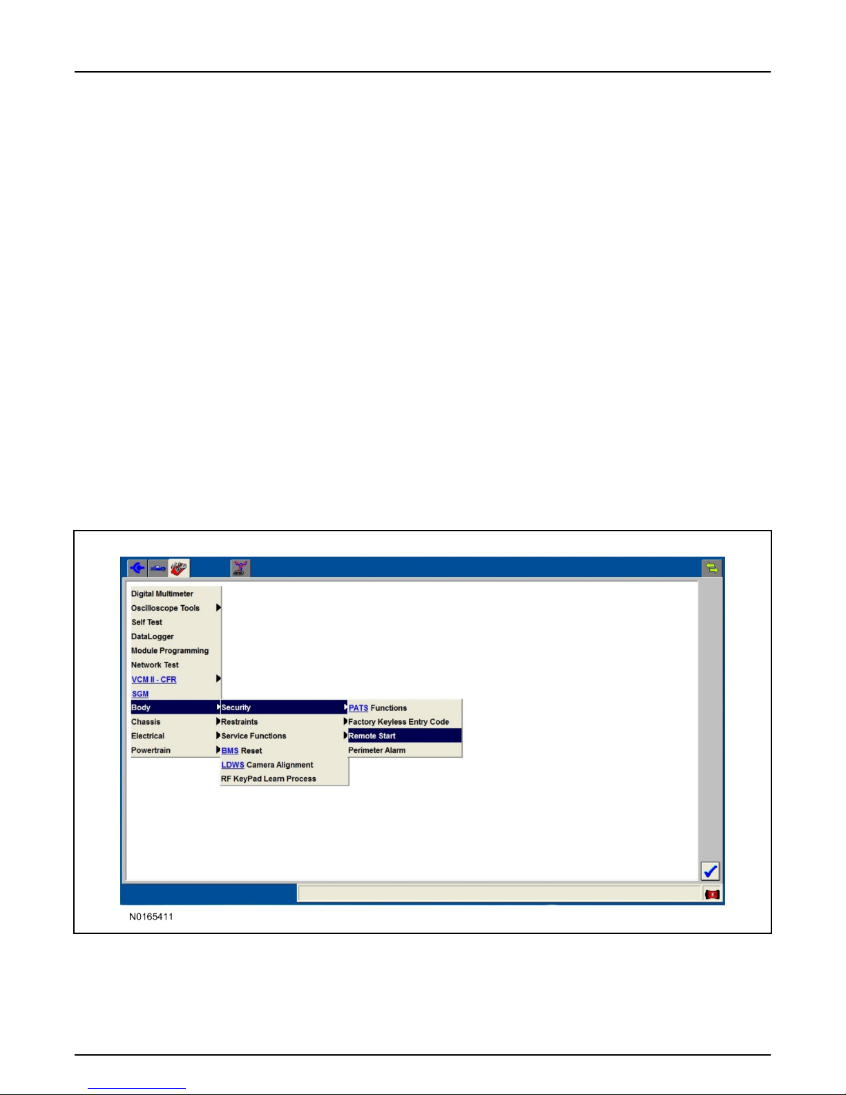
VSS Module - Optional Vehicle Security Features
55. Enable/Disable Vehicle Shock Sensor:
Locate the security jumper supplied in the kit.
• Install the jumper to the VSS module if the shock sensor is to be disabled.
• Not installing and/or removing the jumper from the VSS module will keep the shock sensor
feature enabled.
Page 18
INSTALLATION (Continued)
2016 Explorer
Vehicle Security/Remote Start/Remote Access
17
Page 17 of 27
SK9L2J-19G364-AA
© Copyright Ford 2016 FoMoCo
RMST Activation - Key Start Only
NOTE:
For vehicles equipped with push button start, proceed to Step 62 within the "Programming Key Fobs"
section of this manual.
56. Verify that the IDS is updated to the most current version.
57. Connect IDS.
• Follow the prompts to select new vehicle session.
• Enter VIN.
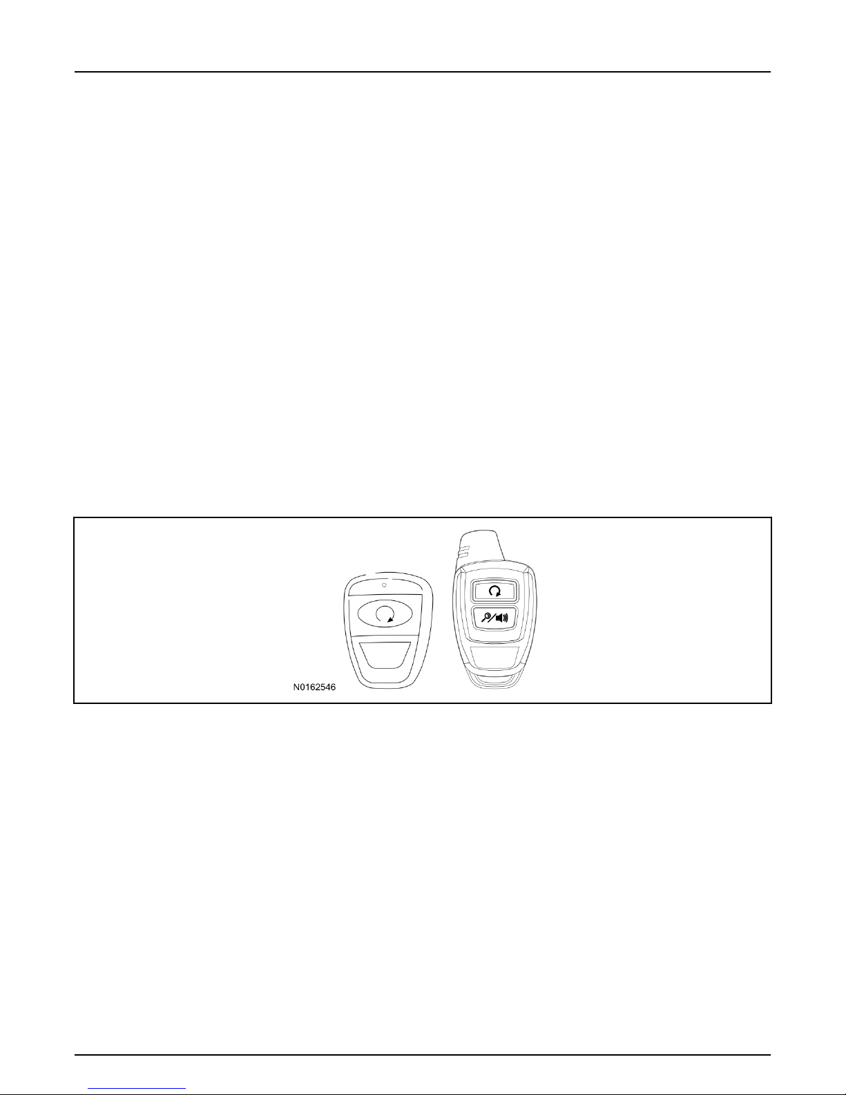
58. Activate the remote start using the IDS.
• Select the Tool Box icon.
• Select Body.
• Select Security.
• Select Remote Start.
• Verify that the information on the IDS screen is correct and all procedures have been followed.
• Select Yes. This will enable the remote start function on the vehicle.
Page 19
INSTALLATION (Continued)
2016 Explorer
Vehicle Security/Remote Start/Remote Access
18
Page 18 of 27
SK9L2J-19G364-AA
© Copyright Ford 2016 FoMoCo
59. For vehicles equipped with standard message center, verify that the remote start option now
appears.
• Using the Select and Arrow buttons on the steering wheel, select Settings.
• Select Convenience.
• Select Remote Start.
• Select System.
• Verify that the remote start system is checked.
60. For vehicles equipped with advanced message center, verify that the remote start option now
appears.
• Using the Select and Arrow buttons on the steering wheel, select Settings.
• Select Vehicle Settings.
• Select Vehicle.
• Select Remote Start System.
• Verify that the remote start system is enabled.
Programming Key Fobs
61. Key Start Vehicles:
NOTE:
These steps must be performed with the VSS module security jumper removed if previously
installed. For additional information refer to "VSS Module - Optional Vehicle Security Features".
1 Start with doors unlocked
2 Driver's door open (remaining open throughout)
3 Verify that the gearshift lever is in the "PARK" position.
4 Depress and hold brake pedal.
5 Start with ignition key OFF.
6 Cycle ignition key to the ON then OFF position 5 times, then back to the ON position a 6th time.
▪ The horn will honk 3 times to indicate transmitter learn mode access.
Page 20

INSTALLATION (Continued)
2016 Explorer
Vehicle Security/Remote Start/Remote Access
19
Page 19 of 27
SK9L2J-19G364-AA
© Copyright Ford 2016 FoMoCo
7 Press the START button on each transmitter you wish to program. The horn will honk 1 time
each time the START button is pressed to indicated the transmitter has been learned.
8 Cycle ignition key to the OFF position to exit transmitter learn mode.
9 NOTE:
If the security jumper is installed the vehicle security features are disabled.
If previously removed, reinstall the VSS module security jumper. For additional information,
refer to "VSS Module - Optional Vehicle Security Features".
62. Push Button Start Vehicles:
NOTE:
These steps must be performed with the VSS module security jumper removed if previously
installed. For additional information refer to "VSS Module - Optional Vehicle Security Features".
NOTE:
The following steps must be performed with the driver door open.
1 Open door and press unlock.
2 Enter the vehicle with the vehicle key(s) and key fobs you wish to program.
3 Depress and hold brake pedal.
4 Press the start/stop button.
5 After the vehicle starts, press the start/stop button to shut down.
6 Repeat steps 4 and 5 an additional five times, ending in ignition ON, engine ON.
7 Release the brake pedal, the horn should honk 3 times.
8 Press the start stop/button on each fob you wish to program. The horn should honk each time the
button is pressed to indicate the transmitter has been programmed.
9 Cycle ignition to the OFF position to exit transmitter learn mode.
10 NOTE:
If the security jumper is installed the vehicle security features are disabled.
If previously removed, reinstall the VSS module security jumper. For additional information,
refer to "VSS Module - Optional Vehicle Security Features".
RMST Functional Test
NOTE:
Do not put a key in the ignition for the following steps.
63. Make sure the shift lever is in PARK and the ignition is in the OFF position. Remove all keys from
the vehicle.
64. Close the hood.
65. Close all of the vehicle doors.
66. Start the vehicle by pressing the remote start button twice on the remote start key fob.
Page 21
INSTALLATION (Continued)
2016 Explorer
Vehicle Security/Remote Start/Remote Access
20
Page 20 of 27
SK9L2J-19G364-AA
© Copyright Ford 2016 FoMoCo
67. Confirm the remote start works with the vehicle in park and with the hood and doors closed.
68. Open the hood.
69. Confirm the engine shuts off.
70. NOTE:
Vehicle doors should be closed while performing this step.
Attempt to remote start with the hood open. Confirm that the vehicle will not start with the hood
open.
Please contact 1-800-FORD-KEY with any issues regarding hardware or kit contents.
71. See the Scalable Remote Start System Diagnosis Guide to resolve issues identified by the functional
test.
III. Remote Access (RMU) Upgrade "Sold Separately"
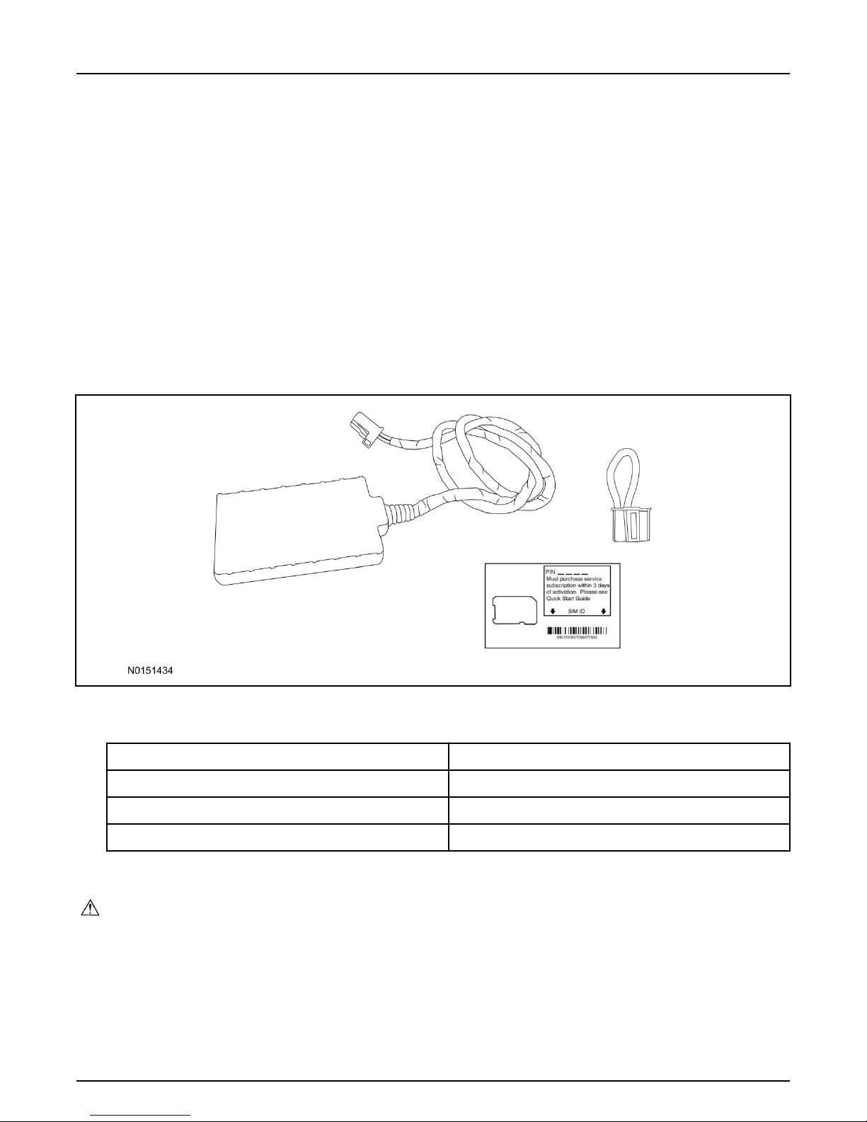
72. Review the RMU upgrade components.
Optional Components — Remote Access (RMU) Upgrade "Sold Separately"
QUANTITY DESCRIPTION
1 Remote Messaging Unit (RMU)
1 SIM Card Carrier
1 Security Jumper
73. If previously installed, remove the LH lower IP insulator.
CAUTION:
Carefully route and secure module and harnesses so that they do not interfere with moving parts
or linkages.
NOTE:
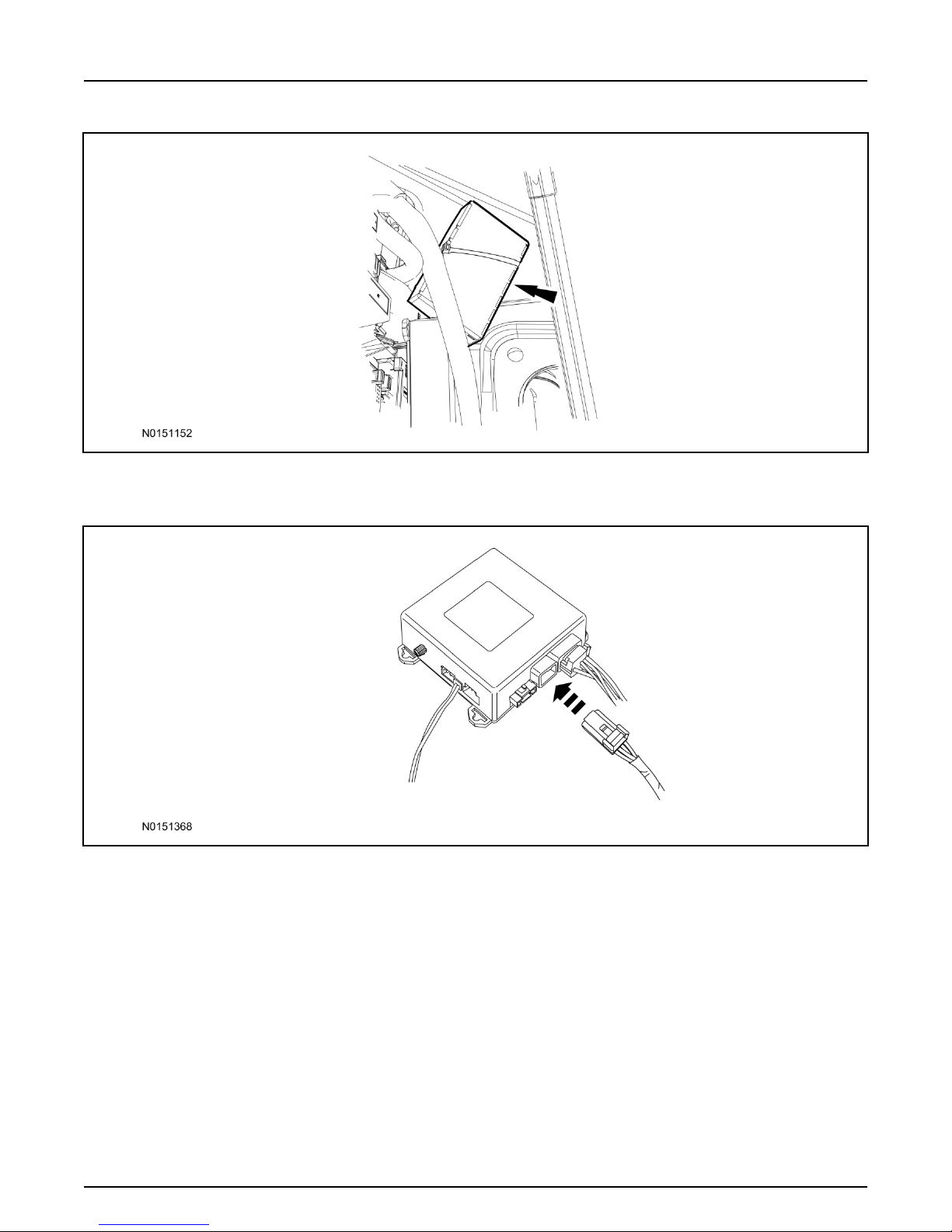
For proper range of operation, the RMU must be installed as shown in the diagram below.
74. Using tie-straps secure the RMU to the IP harness near the previously installed VSS module.
Page 22
INSTALLATION (Continued)
2016 Explorer
Vehicle Security/Remote Start/Remote Access
21
Page 21 of 27
SK9L2J-19G364-AA
© Copyright Ford 2016 FoMoCo
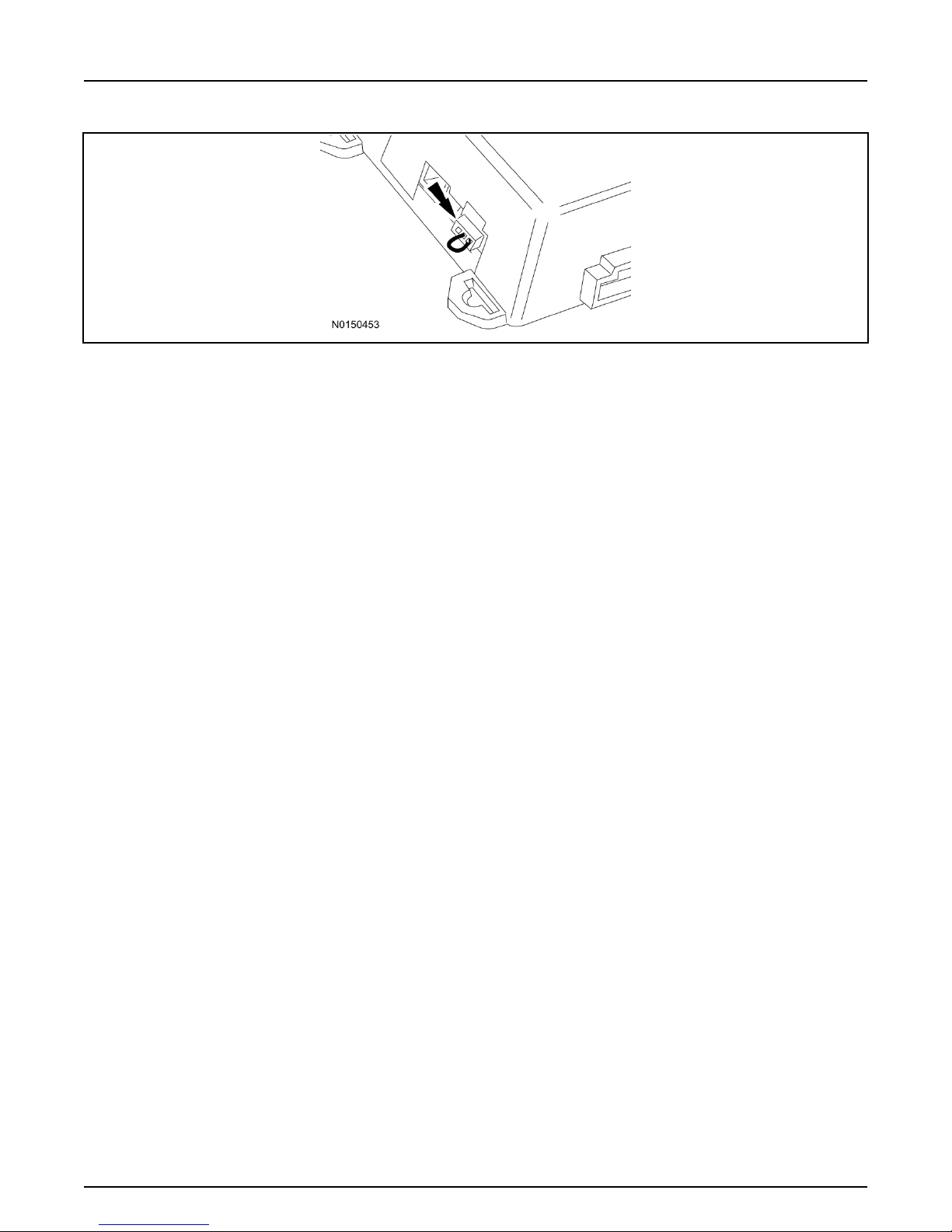
75. Connect the RMU electrical connector to the VSS module.
• Secure the harness with tie-straps.
VSS Module - Optional Vehicle Security Features
76. Enable/Disable Vehicle Security Features:
Locate the security jumper supplied in the kit.
• Install the jumper to the VSS module if the vehicle security features are to be disabled.
• Not installing and/or removing the jumper from the VSS module will keep the vehicle security
features
enabled.
Page 23
INSTALLATION (Continued)
2016 Explorer
Vehicle Security/Remote Start/Remote Access
22
Page 22 of 27
SK9L2J-19G364-AA
© Copyright Ford 2016 FoMoCo
77. Install the LH lower IP insulator.
Remote Start Activation - Key Start Vehicles (Without Factory Remote Start)
78. Cycle ignition OFF, ON, OFF one time to learn RMST to the vehicle.
79. Verify that the IDS is updated to the most current version.
80. Connect IDS.
•
Follow the prompts to select new vehicle session.
• Enter VIN.
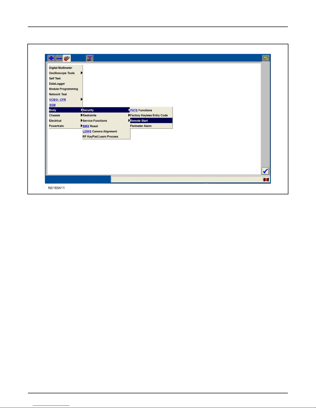
81. Activate the remote start using the IDS.
• Select the Tool Box icon.
• Select Body.
• Select Security.
• Select Remote Start.
• Verify that the information on the IDS screen is correct and all procedures have been followed.
• Select Yes. This will enable the remote start function on the vehicle.
Page 24
INSTALLATION (Continued)
2016 Explorer
Vehicle Security/Remote Start/Remote Access
23
Page 23 of 27
SK9L2J-19G364-AA
© Copyright Ford 2016 FoMoCo
82. For vehicles equipped with standard message center, verify that the remote start option now
appears.
• Using the Select and Arrow buttons on the steering wheel, select Settings.
• Select Convenience.
• Select Remote Start.
•
Select System.
• Verify that the remote start system is checked.
83. For vehicles equipped with advanced message center, verify that the remote start option now
appears.
• Using the Select and Arrow buttons on the steering wheel, select Settings.
• Select Vehicle Settings.
• Select Vehicle.
• Select Remote Start System.
• Verify that the remote start system is enabled.
RMU Activation
NOTE:
Please note that the Remote Access application that is used to start the vehicle for this RMST kit will
only work with iPhone and Android phones.
Page 25
INSTALLATION (Continued)
2016 Explorer
Vehicle Security/Remote Start/Remote Access
24
Page 24 of 27
SK9L2J-19G364-AA
© Copyright Ford 2016 FoMoCo
84. For RMU activation the following information from the customer is recommended to provide them
with electronic notification for app retrieval:
1 Email Address
2 Cell Phone Number
3 Cell Phone Carrier Company
85. Log on to your Professional Technician Society (PTS) account and enter the vehicle information.
1
Select "Vehicle Id".
2 Select "By Year & Model"
3 Choose the year & model of the vehicle and then select "GO".
4 Hover over the "Workshop" tab.
5 Select the "Accessory Installation" menu item.
6 Under the "Electrical" heading, select the "Remote Access Activation" link (first time users will
need to agree to terms & conditions).
7 Select the "Install or Diagnose" link.
NOTE:
If you are not directed to the screen shown below (or user agreement screen for first time users), make
sure your internet browser zone settings are set to medium. This setting can be found in your browsers
"internet options" under the "privacy" tab.
Page 26
INSTALLATION (Continued)
2016 Explorer
Vehicle Security/Remote Start/Remote Access
25
Page 25 of 27
SK9L2J-19G364-AA
© Copyright Ford 2016 FoMoCo
86. Once on the "Install" page, enter the SIM ID code that was provided with the RMST kit. Select
"Begin or Continue Installation".
87. Click on the "On screen steps 1-6", and follow the on screen instructions to complete the
installation.
Page 27
INSTALLATION (Continued)
2016 Explorer
Vehicle Security/Remote Start/Remote Access
26
Page 26 of 27
SK9L2J-19G364-AA
© Copyright Ford 2016 FoMoCo
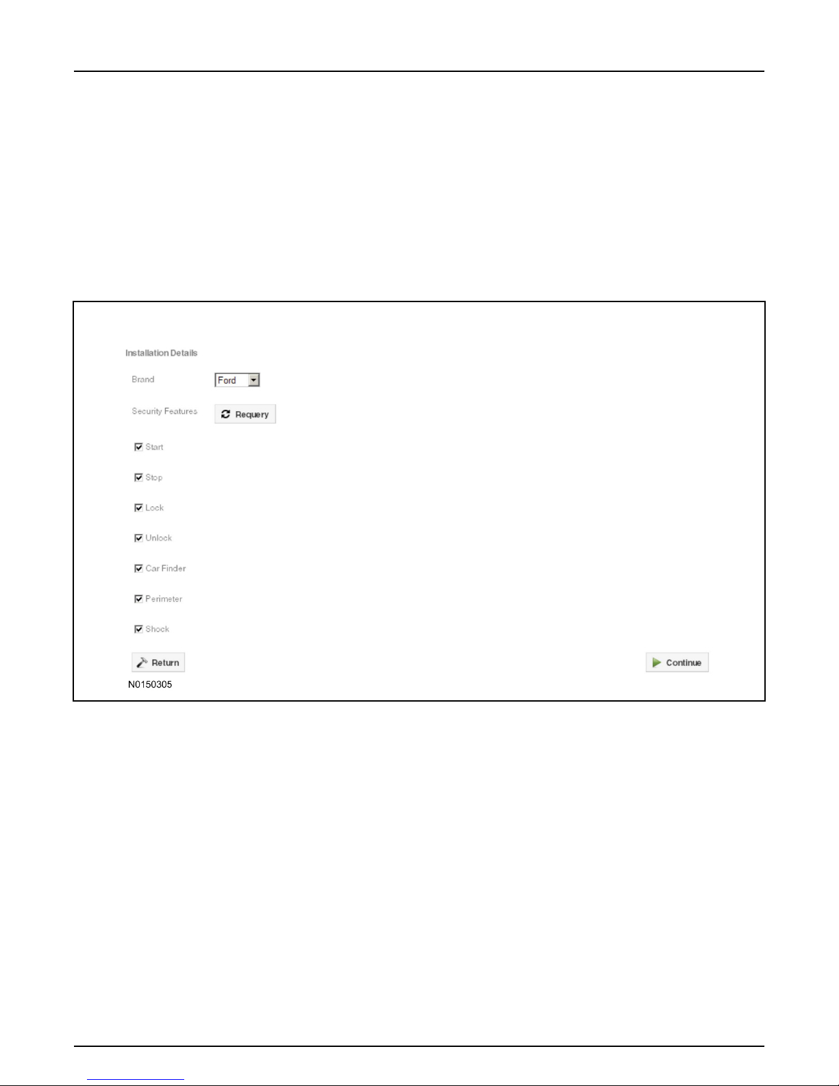
NOTE:
The following step will complete the activation process, when you are directed to a screen similar to the
one below ensure the correct vehicle brand is selected and that all applicable features are enabled.
NOTE:
The "perimeter" and "shock" settings below are optional features and should only be selected when
security features are enabled.
NOTE:
On screen Step 3 shown below.
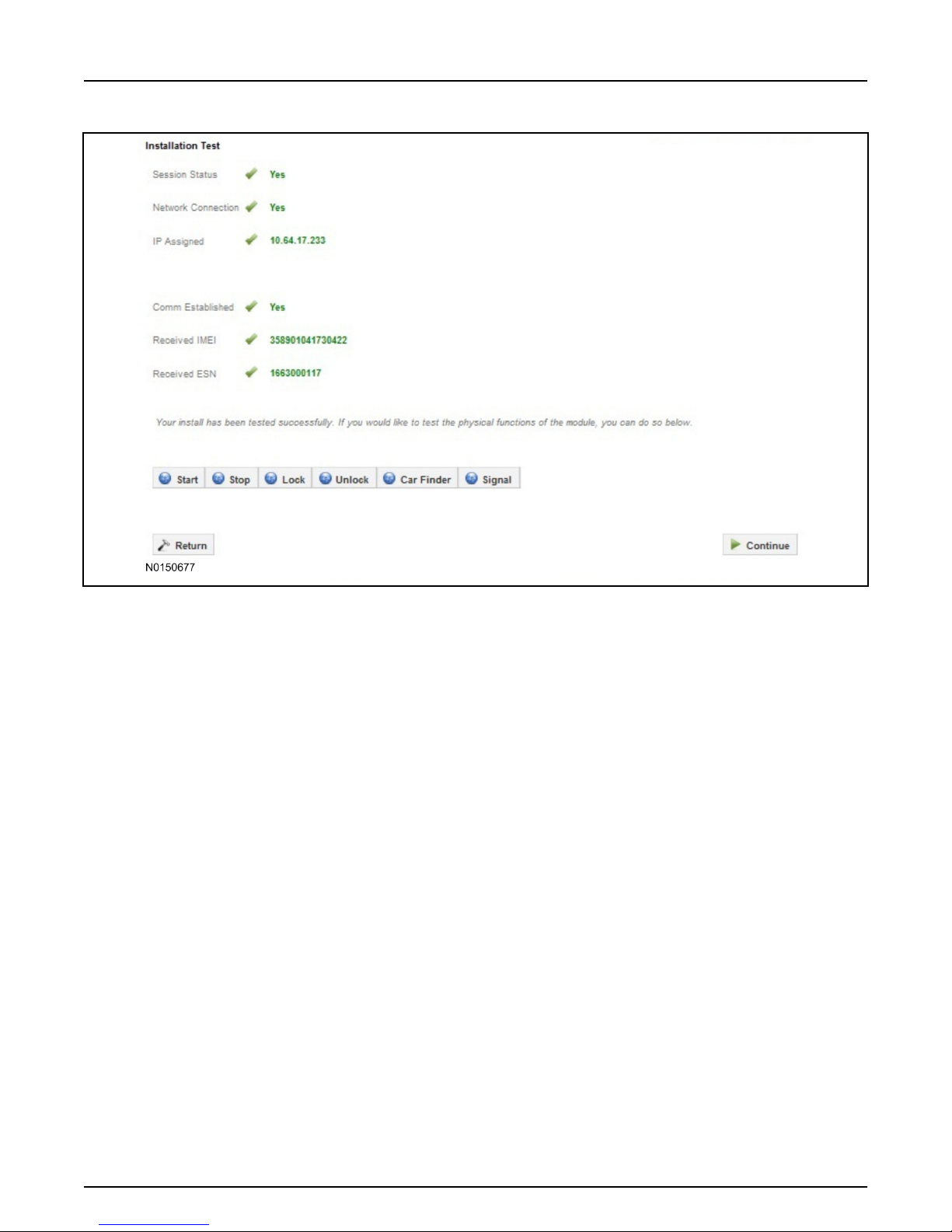
88. NOTE:
On screen Step 4 shown below.
Perform a functional check of the system by testing each of the available features.
• Start/Stop function
• Lock/Unlock function
• Car finder
• Signal (for troubleshooting only)
Page 28
INSTALLATION (Continued)
2016 Explorer
Vehicle Security/Remote Start/Remote Access
27
Page 27 of 27
SK9L2J-19G364-AA
© Copyright Ford 2016 FoMoCo
NOTE:
All tests above must be completed in order to move to the next step. If any of the listed functions fail,
move the vehicle to an outside location and retest.
Key Start Vehicles Only
NOTE:
In the event start or stop fail, refer to the "Remote Start Activation" section in this manual.
NOTE:
In the event lock/unlock or car find fail, refer to the "Learn VSS to Vehicle" section in this manual.
All Vehicles
89. Once the hardware installation and RMU activation process is complete, record the 4-digit PIN on
the SIM card carrier. Provide the SIM card carrier to the customer so they can add this system to
their Remote Access Account. Customer must have both the 4-digit PIN and SIM ID to activate/add
their vehicle to their Remote Access Account.
90. If the customer agrees, you may push the mobile application to the customer. You will need the
customer's phone number and cellular carrier. If the customer opts to install the application
themselves, they can locate it in their mobile app store.
Please contact 1-800-FORD-KEY with any issues regarding hardware or kit contents.
 Loading...