

Ford 1975 Mustang II Owner's Manual


www.carburetor-manual.com
Would you like some Free Manuals?
http://carburetor-manual.com/free-shop-manual-club-t-13.html
Also visit http://freeshopmanual.com for more Free Manuals
Also Visit my website for 7 FREE Download Manuals starting
with this one.
"The ABC's of Carburetion"
Click Here Now
file:///C|/Documents%20and%20Settings/Tim/Desktop/carburetor-manual-welcome/index.htm[4/25/2009 11:42:20 AM]
INDEX
Accessories
....•.....
;
........
82
Air Conditioner
.......•........
19
Anti-Theft Alarm
System
...•.....
29
Appearance Protection
..........
62
Chrome and Bright Metal Care
....
63
Cleaning
Seat and Shoulder
Belt Webbing
................
64
Polishing
•...................
63
Upholstery and Interior
Trim Cleaning
...............
64
Vinyl Roof
..................
64
Washing
•........•....•..•...
62
White Sidewall Tires
...........
64
Ashtray and Lighter
••..........
27
Automatic Transmission
..•...•..
39
Battery
.....................•
58
Brake Fluid
.................•.
57
Brakes
....•...•...•..........
27
Bulb Chart
•...•.......••......
77
Car
Owning Made Easier . . . . . . . •
..
89
Order Form
....•••.•..•......
90
Changing a Tire
.....•......•...
46
Climate Control
.........•......
17
Heater/Defroster. . . . . . . . . • . . .
.•
17
Air Conditioner
................
19
Clock
........................
27
Coolant
..............•.•......
54
Checking Coolant Level
.........
54
Checking Hose
......•.....••..
56
Coolant
Refill. . . . . . . . . . . . . . .
..
55
Coolant Specification . . . . . . . . .
..
56
Replacing Coolant
.............
55
Dealer Assistance
...........•...
79
District
Office Assistance . . . . . . .
..
79
Door Handles and Locks
.•.......
28
Inside Door Handles . . . . . . . . . .
..
28
Inside Door Locks
.............
28
Outside Door Locks
..........
"
28
Ecology............
..........
3
Economy Driving Tips
...........
44
Electric Rear Window Defroster
....
18
Emission Control
Systems
........
69
Definitions . . . . . . . . . . . .
• . . . .
..
69
Emission
Systems Warranties
.....
70
Symptoms Indicating Need
For
Service
..................
73
Engine Compartment
Nomenclature. . . . .
• . . . . . • . . .
..
53
Fuel
..................•......
50
Filler Tube and Filler Cap
.......
51
Octane Rating
................
51
Tank Capacity
................
51
Fuses and Circuit Breakers
........
74
Glove
Box.
. . . . . . . . . . . . . . . . . .
..
27
Hazard Flasher . . . . . . . . . . . . . . .
..
16
Headlight/Dome Light Switch
.....
16
Heater/Defroster. . . . . . . . . . . . . .
..
17
Headlight Dimmer Switch. . . . . . .
•.
16
Hood, Opening . . . . . . . . . . . . . . .
..
36
Horn
........................
26
How To Use This
Manual..
. . . . .
..
1
Ignition
Switch.
. . . . . . . . . . . . . .
..
11
Ignition Buzzer. . . . . . . . . . . . . . •
..
12
Important Message For
Owners
....
69
Infant and Child
Safety
Restraints . . . . . . . . . . . . . . . . . .
..
34
Introduction.
. . . . . . . . . . . . . . . . . . 1
Instruments and Controls
.........
10
Instrument Panellllustration
and Nomenclature
..............
10
Jumper Cables, Use
of
..........•
47
Keys and Key Records . . . . . . . . .
..
11
Lifeguard Safety Features
•.......
2
Light Controls
...
'. . . . . . . . . . . .
..
16
Lubrication Recommendations. . .
..
78
Maintenance Manuals and
Tool Kits
.....................
85
Order
Forms.
. . . . . . . . . • . . . . .
..
86
Maintenance Services
General Checklist . . . . . . . . . . . .
..
67
Record
Retention.
. . . . . . . . . . .
..
71
Scheduled Services . . . . . . . . . . .
..
4
Manual Transmission
......
.
....
" 41
Map
Light
....................
16
Minor Troubleshooting Guide
.....
65
Mirrors
......................
35
L.H.
Side View Mirror
(Remote Control) . . . . . . . . . . .
..
35
R.H. Side View Mirror
(Remote Control) . . . . . . . . . . .
..
35
Rear View Mirror . . . . . . . . . . . .
..
35
New Car Break-In. . . . . . . . . . . . .
..
44
Oil and Filter
...............
.
..
51
Changing
Oil and Filter
.........
52
Checking
Oil Level
and Adding
Oil
;.............
51

INDEX
Oil Filter
.............
..
.....
52
Oil Quality . . .
..........
. .
....
52
Oil Viscosity
...••
. . •
•.....•...
52
Odometer.
. . . . . . • . • . . . • • • . . .
..
28
Parking Brake ...... .
..•....
.. " 27
Power Steering Fluid ........•..•.
57
Pushing and Towing . . . . . . .
• . . .
..
48
Radios
AM
Push Button Tuning
........
21
AM
Radio
....•...•.
. . . .......
21
FM
and FM/Stereo Tuning ...
....
21
AM/FM Monaural Radio. . . . . . .
..
22
AM/FM
Stereo Radio
•.••
.....
. . 23
AM/FM
Stereo Radio/Tape .
.....
24
Refill Capacities
•.........•...•
76
Routine
Service . . .
.......
....
. . 50
Checking Lights
..........
.
....
58
Cleaning Lights
.•........•....
59
Oeaning Mirrors . . . . . . . . . . . . .
..
59
Refilling Windshield Washer
Reservoir. . . . . . . . . . . . . . . . . .
..
60
Replacing Air Filter
.....
..
.....
59
Replacing Windshield
Wiper Blades
.....
. .
...
...
...
59
Safety Restraints
..........
.
....
31
Adjusting Shoulder Belt
.......
..
32
Bu
ckle
Up
To
Start .•••
.....
. . .
31
Engine Restart .
.•........
. . .
..
33
Rear Lap Belts .
...
..
..........
33
Seat Belt Maintenance
.. ..
. .....
33
To Enter Rear
Seats
....•.....
.
33
Front
Lap-Shoulder Belts . . . . . . . .
31
Unfasten Seat Belts
...
. . . . .
....
33
Seats and Controls
........
..
•...
30
Manual Seats
.................
30
Fold Down Rear Seat .•.......
..
31
Seatback Release
........
.
.....
30
Service
As
sistance .....
...
.....
. 1
Service Literature (Order Forms) . " 83
Spare Tire
.....•.....•.......•
46
Spare Tire Lock .
.•.......
.
...
" 46
Special Driving Situations
......
. .
43
Driving
on
Sand, Snow , Ice
or
Slippery
Roads.
. . . . . . . . . .
..
43
Rocking the
Car . . . . . . . . . . . . .
..
43
Specifications and Capacities . . . .
..
74
Speedometer
..••.........•....
28
Starter Interlock System
....
.....
33
Starter Operation
............
.
..
38
Starting The Engine . . . . .....
. .
..
36
Steering Column Lock Button .....
12
Sun Roof
.. ..
....
.....
........
36
Tachometer
........•.
. . •• . . . . .
28
Tires and Tire Care . . . . . . . . . . . .
..
60
High Speed Driving
....
. . .
...
... 61
Inflation Pressure Limits .
...
. . . " 60
Original Equipment Tires . .
....
" 60
Rotate Tires and Wheels . . . . . . .
..
62
Snow Tires,
Use
of ..........
...
61
Tire Replacement .............
. .
61
Tires, Changing
...
........
. . . . 46
Towing the Car . .
..
. ....
........
48
Trailer Towing
........
...
......
48
Trailer Brakes . .
....
..
. . .
....
" 49
Hitches
•.............
..
...
. " 49
Loads
.........
..
...
. . .
......
49
Safety Chains . . . . . . . . . . . . . . .
..
49
Towing Tips . . . . . . . . . . . . . . . . . .
50
Transmission Fluid . . . . . . . . . . . .
..
56
Trunk, Opening. . . . . . . . . . . . . . . . . 36
Turn
Signals
..........
...
...
... 17
Vehicle Identification
Number (YIN) . . .
...
. . . .
......
3
Warning Indicators
.....
. . .... .
..
12
Gauges . . .
..
. ....
...
. .
...
.... 14
Lights .... . .
..........
.
...
... 12
Warranties ............
.
...
2,
70,
71
Windows .
...
....
. . .
.......
...
30
Manual Windows . .
...
...
......
30
Rear
Quarter Windows . . . . . . . .
..
30
Windshield Wipers and Washers. . .
..
15

INTRODUCTION
Welcome
Ford welcomes you to the growing group
of
discerning people who own
and drive Ford-built vehicles.
We
take great pride in the long tradition
of
quality products and superior values that the Ford name represents.
This owner's manual
has, been written to help you enjoy many miles
of
motoring pleasure in your new car.
You, Your Car,
and
Ford
New
Car Break-In
Your new car will not require an extensive "break-in", however,
we
recommend that you limit your maximum speed to 70 mph,
or
the
lawful speed limit, whichever
is
lower, during the first 1000 'miles. For
further break-in instructions see page
44
.
No
Unhappy Owners
Ford
is
proud
of
its vehicles and the expert service available from its
dealers. When you buy a new car from
us
we
want you
to
be completely
pleased with it.
Our goal
is
to see that there are
No
Unhappy Owners.
Service Assistance
Your authorized dealers want you to be completely satisfied with your
new car. But,
if
you feel that,you require service assistance beyond that
which your dealer is able
to
provide, the Ford Motor Company District
or Regional Office in your area
will
be pleased to work with you and
your dealer.
We
have district and regional offices set up throughout the
United States and Canada to help resolve any service questions you may
have. For more information about the function
of
these District
or
Region-
al
Offices and the address
of
the office in your area, see the District Office
Assistance Section in the back
of
this manual. When
we
say
we
want you
to be
100% satisfied,
we
mean it!
How to
Use
This Manual
Each year Ford introduces new features designed to increase your driving
pleasure.
This owner's manual will familiarize you with these improve-
ments
as
well
as
other important facts you should know about your car.
You are urged
to
read this manual from cover
to
cover.
We
wrote this manual especially for you.
We
hope you use
it
to
get to
know your new car and learn how
to
get the most enjoyment from it.
First you'll become familiar with the various instruments and controls.
As
you read further, you'll get some tips on how
to
drive on slippery
roads, how to break-in your new car, and how
to
drive economically.
INTRODUCTION
This manual also includes sections
on
the maintenance
of
the beauty
of
your new car and the services that are needed
to
keep
it
in
excellent
running condition.
In
the back
of
the manual there are some convenient
forms for do-it-yourself mechanics
to
order car shop manuals.
After reading this owner's manual , be sure to keep
it
in your car
as
a ready
reference when you need it.
See your. authorized dealer for any further
information. He'll be glad
to
answer any questions you may have about
operating the equipment on your new car.
Warranties
The warranties covering your new car are
an
integral part
of
your
purchase
order. Information about the warranties can be found in the Warranty
Facts Booklet and under Emissions
Systems in the Scheduled Maintenance
Section
of
this manual. Read this information carefully because every-
thing that
is
covered in the warranties
is
stated in precise terms.
Lifeguard Safety Features
The car you have just purchased has improved impact resistant bumpers.
Specifically, the front and rear bumpers meet Federal Standards for
up
to
five
mph frontal and rear impact protection straight
into
a flat, vertical
ftxed barrier without hindering normal operation
of
the car's
hood
and
trunk latching, fuel, cooling, and exhaust systems or
of
the propulsion ,
. suspension, steering, electrical or braking systems. Tests show
that
with
bumper guards, no substantial damage
to
sheet metal should result from
such a barrier impact at or below these speeds.
Every new Ford Motor Company car includes the following
lifeguard
Design Safety Features:
2
Dual hydraulic brake systems with warning light
Energy-absorbing instrument panel with padding
High strength larninate safety glass windshield
Double-yoke safety door latches and safety hinges
Steel guardrails in side doors
Head restraints for front outboard occupants
Energy-absorbing steering column
Starter interlock system (except Canada)
Three-point lap and shoulder belt restraint system
Self~locking
front seatbacks
INTRODUCTION
Ecology
WE,
TOO, ARE COMMITTED TO IMPROVING THE ENVIRONMENT.
WON'T YOU JOIN
US
IN THE FIGHT FOR CLEANER AIR?
Ford Motor
Company vehicles for 1975 have been certified
as
meeting
ap-
plicable emissions standards. In order
to
do so,
it
has been necessary to
make certain adjustments,and
modifi~ations
that
may reduce engine
smoothness under certain operating conditions. Any minor inconvenience
that
might
be caused by these adjustments
is
more than outweighed by the
fundamental objective
of
IMPROVING OUR ENVIRONMENT.
The catalytic converter in your automobile
(if
equipped) represents the
latest advancement in our continuing effort to improve the quality
of
the
air
we
all
breathe. This converter changes most exhaust emissions into
water vapor and carbon dioxide. To assure that the converter
as
well
as
all
other devices and systems, operates effectively,
it
is
imperative that
you use only unleaded fuel and have the services listed in the maintenance
schedule performed at the specified time and mileage intervals.
It
also
is
important that you contact your dealer for service
at
the first indication
of
any change in the normal performance
of
your
vehicle.
Additionally, you must be careful to avoid running
out
of
gasoline, or
turning
off
the ignition while the vehicle
is
in motion, especially at high
speeds because this can create high temperatures that may damage the
catalytic converter.
Engine
compartment and exhaust system temperatures for the 1975 car
lines may
be
higher than in prior model years due to the added emission
control devices needed
to
comply with the 1975 Government Emission
Standards. To help minimize heat build up, you should avoid extended or
unnecessary idling
of
the engine. This is particularly important for
"off
road" operation, after high speed or high load driving, or where there
is
an
indication
of
abnormal engine or vehicle performance.
Additionally, high speed idling
of
the engine
(5
minutes
or
more) could
produce excessive system temperatures that can damage your vehicle.
Within about
30
seconds after starting the engine you should depress and
release the acceleratorpedal to produce a lower idle speed.
Several models will be equipped with exhaust system shields which should
be
inspected for deterioration and cleaned
of
debris
as
recommended in
the Scheduled Maintenance Services.
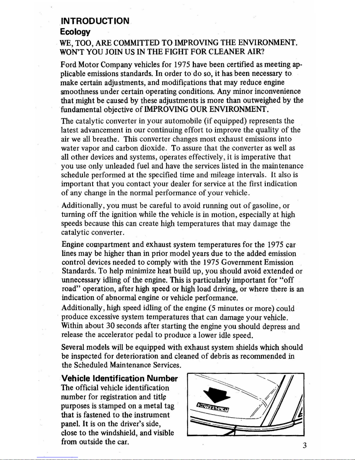
Vehicle Identification Number
The official vehicle identification
number for registration and
tit1\!
purposes
is
stamped on a metal tag
that
is
fastened
to
the instrument
panel.
It
is
on the driver's side,
close
to
the windshield, and visible
from outside the car.
3

INTRODUCTION
If
you ever find
it
necessary
to
correspond with Ford Parts and Service
Division about your car, please include the II-digit vehicle identification
number.
You'll also find this number, along with some other important identifying
information, on the Vehicle Certification Label, which is attached
to
the
left door lock pillar. The certification label is made
of
special material
to
guard against altering it.
If
it
is
tampered with or removed,
it
will
be destroyed or the word VOID will appear. Vehicleloading and tire inflation
pressure levels are also shown on a label attached
to
the rear face
of
the
passenger right-hand door.
NOTICE-The description and specifications contained in this manual were
in effect at the time the book
was
approved for·printing_ The Ford Motor
Companies reserve the right
to
discontinue models at any time, or to
change specifications or design, without notice and without incurring
obligation_
SCHEDULED MAINTENANCE SERVICES
A special decal has been placed on
or
near your engine
to
provide engine
identification and other information. This· decal provides engine identification
by
displacement
as
well
as
certain specifications. Other specifications
for maintenance service adjustments are published in the 1975
Ford
Car
Specificatiqns Manual. For a copy
of
this manual send 60 cents (includes
postage)
to
Ford Service Publications, P.O. Box 07150, Detroit, Michigan,
48207. In Canada, address request
to
Ford Motor Co.
of
Canada, Ltd.,
Service Publications,
P.O. Box 905, Station
U,
Toronto, Ontario, M8Z5P9,
Canada.
The following charts detail the maintenance services which must be performed at the indicated intervals, followjng the procedures
in
the 1975
Ford Car Shop Manual. Maintenance service adjustments
MUST
CON-
FORM TO SPECIFICA TIONS contained therein and
as
published in
the
1975 Car Specifications Manual, or the emission systems may become in-
operative_ These services are not covered
by
warranty, and you will be
charged for labor, parts and lubricants used.
NOTE-Three maintenance schedules are specified for 1975 passenger cars.
They
are
identified
by
the letters A,
Band
C.
The schedule which applies
to
your vehicle
is
identified by a decal on the glove box door which displays
either an
A,
B or
C,
as
applicable. This information also appears on the
Vehicle Emission Control Information Decal, which
is
located on or near
the engine.
4
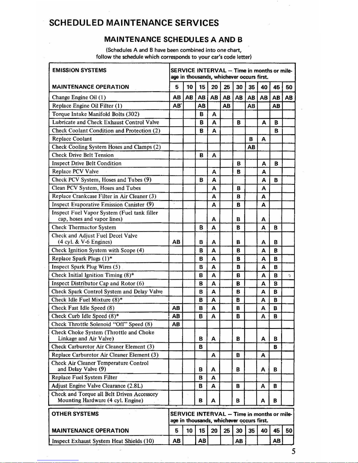
SCHEDULED MAINTENANCE SERVICES
MAINTENANCE SCHEDULES A AND B
(Schedules A and B have been combined into
one
chart,
follow
the
schedule which corresponds
to
your
car's
code
letter)
EMISSION SYSTEMS
SERVICE INTERVAL
~
.
Time
in
months
or
mile-
age
in
thousands, whichever occurs
first_
MAINTENANCE OPERATION
5
10
15 20 25 30
35 40
45
50
Change Engine
Oil
(I)
AB
AB AB
AB
AB
AB AB
AB
AB
AB
Replace Engine Oil
Filter
(I)
AB-
AB
AB
AB AB
Torque Intake Manifold Bolts (302)
B
A
Lubricate and
Check Exhaust Control Valve
B
A B
A
B
Check Coolant Condition and Protection
(2)
B A B
Replace
Coolant
B A
Check
Cooling System Hoses and Clamps (2)
AB
Check Drive Belt Tension
B
A
Inspect Drive Belt
Condition
B A B
Replace
PCV Va
lve
A B A
Check PCV System, Hoses and Tubes
(9)
B A A
B
Clean PCV System, Hoses and Tubes
A B A
Replace
Crankcase Filter in Air Cleaner (3)
A B
A
Inspect Evaporative Emission
Canister (9)
A B A
Inspect Fuel Vapor System (Fuel tank filler
cap, hoses and vapor lines)
A B
A
Check Therma
ctor
System
B A B A B
Check and Adjust Fuel Decel Valve
(4
cyl. & V
-6
Engines)
AB B
A B A B
Check Ignition System with Scope
(4)
B
A
B A
B
Replace Spark
Plugs (1)*
B
A B A B
Inspect Spark
Plug Wires (5)
B
A B
A
B
Check Initial Ignition Timing (8)*
B
A B A B
-,
Inspect Distributor Cap and
Rotor
(6)
B A B A
B
Check Spark Control System and Delay Valve
B A B A
B
Check Idle Fuel Mixture (8
)'
B A B A
B
Check Fast Idle Speed (8)
AB
B
A
B
A B
Check Curb Idle Speed
(8)
'
AB
B A B A B
Check
Throttl
e Solenoid "Off" Speed (8)
AB
Check Choke System (Throttle and Choke
Linkage and Air Valve)
B
A B A B
Check Carburetor Air Cleaner Element (3)
B
B
Replace
Carbure
tor
Air Cleaner Element
(3)
A B A
Check Air Cleaner Temperature Control
and Delay Valve (9)
B A B A
B
Replace Fuel
System Filter
B
A
Adjust Engine Valve Clearance
(2
.8L)
B A B A
B
Check and Torque
all
Belt Driven Accessory
Mounting Hardware
(4
cyl. Engine)
B A B A
B
OTHER
SYSTEMS
SERVICE INTERVAL
~
Time in months
or
mile-
age
in thousands, whichever <!ccurs first.
MAINTENANCE OPERATION
5
10
15 20 25
30135
40145
50
Inspect Exhaust System Heat Shields (10) AB
ABI
ABI
lAB
5

SCHEDULED MAINTENANCE SERVICES
OTHER SYSTEMS
(Cont'd.)
SERVICE INTERVAL - Time in months
or
mile-
again
thousands, whiche'ler occurs first.
MAINTENANCE
OPERATION
5
10 15
20
25
30
35
40
45
50
Check Automatic Transmission Fluid Level
AB
AB
AB AB
Check Manual Transmission Fluid Level
AB
AB
AB
AB
Check Rear Ax
le
Fluid Level
AB
AB
AB
AB
Check Brake Master Cylinder Fluid Level
AB
AB AB
AB
Oteck
Clutch Pedal Free
Play-adjust
if
required
AB
AB
AB AB
Inspect
Front
Suspension and Steering
Linkage for abnormal looseness or
damaged seals
AB
AB
AB
Adjust Automatic Transmission Bands
(7)
AB
Inspect Brake Lining, Lines, Hoses and
repack front wheel bearing tube
(9)
AB
AB
Lubricate Front Suspension and Steering
Linkage
AB
Drain and Refill Automatic Transmission
Fluid - Continuous
Service Only
AB
NOTES
Refer to Vehicle Emission Control Decal for specifications.
I. Severe
Service Operation -
When
operating your vehicle under any
of
the following conditions,
change engine oil every
2Y,
months
or
2,500 miles; change engine oil filter at the first oil change
and every 5 months
or
5,000 miles
thereafte
r.
Check, clean and regap spark plugs every 5,000
miles.
6
•
Ext
ended period
of
idling
or
low speed operation such
as
police, taxi or door·to·do
or
delivery.
• Operation when outside temperature remains below +
100F for 60 days
or
more
and
most
trips are less
thal'l
10
miles.
• Operation in severe dust condition
s.
2.
If
coolant
is
dirty or rusty in appearance, the system should be drained, cleaned and refilled
with the prescribed solution
of
Ford Cooling System Fluid and water.
Use
only a permanent
type coolant that meets Ford
Specification ESE·M97BI8-<:.
3. More often
if
operated in severe dust condition
s.
4. Scope check includes recheck
at
completion
of
any maintenance, repairs, etc.
5. Repair
or
replace
as
indicated by scope check and verified by continuity check.
6.
Clean
or
replace
as
indicated by scope check.
7. Adjust
at
5,000, 15,
000,30,000
and 45,000 miles for severe service.
8. Adjust
as
required.
9. Adjust, repair
or
replace
as
required.
10. Remove accumulated debris and inspect shields and attachments - repair
or
replace
as
required. Perform each 5,000 miles for severe service usage over
unpaved roadways
or
off
road applications.

SCHEDULED
MAINTENANCE
SERVICES
MAINTENANCE SCHEDULE C
EMISSION SYSTEMS
SERVICE INTERVAL
- Time·
in
months
or
mile-
age
in
thousands, whichever occurs first.
MAINTENANCE OPERATION
6 12
18
24
30
36
42
48
Change engine oil
(l)
SEE FOOTNOTE 1
Replace engine oil filter
(l
)
SEE FOOTNOTE 1
Check fuel deceleration valve (2)
(if
so
eq ui pped)
C
C
C C
C
Adjust Engine Valve Clearance (2.8L)
C C C C
Adjust idle fuel mixture - all except 4 cyl.
C C
Adjust idle fuel mixture - 4 cy
l.
C
C C C C
Adjust fast idle speed - all except 4 cyl.
C
C
Adjust fast idle speed - 4 cyl.
C
C
C
C
c
Adjust curb idle speed and TSP Off-Speed
- all exce
pt
4 cy
l.
C C
Adjust curb idle speed and TSP Off-Speed
-4
cyl.
C C C C
C
Torque intake manifold bolts/nuts
(4 cyl. &
V-6
only)
C
C C C
Replace crankcase-emission filter in air
cleaner (6)
C
C
Check carburetor air cleaner elemen t (6)
C C
Replace carburetor air cleaner element (6)
C C
Lubricate exhaust control valve (if
so
equipped) at each oil change
(l)
C C C C C C C
C
In
spect fuel vapor system (fuel tank filler
cap, hoses and lines) (2)
C
C
Replace all spark plugs
(l)
(Ill
(10)
C C
Replace
ails
park plugs
(l)
(8)
(II)
C
C
C C
Adjust initial ignition timing
C C
Inspect spark plug wires
(l0)
C
C
Inspect spark plug wires
(II)
C C C C
Check spark control systems and delay valve (9)
C C C C
Repla
ce
PCV
valve
/
C C
Cneck
PCV
system, hoses and tubes (2) (9)
C C
Clean
PCV
system, hoses and tubes (2)
C C
Check air cleaner temperature control (9) and
delay valve
C C C C
Check throttle and chok e linkage and delay
valve - all except
4 cy!. .
C C
Check throttle and choke linkage and delay
valve -
4
cyL
C
C C
· C
Check thermactor system
Of
so equipped) (9)
C
C
Repla
ce
fuel system filter
C
Check EGR system (3) (2)
(9)
and delay valve
C C C C
Check coolant condition and protection (4)
C C
C
Replace coolant (5) C
Check cooli
ng
system hoses· and clamps C C
Check
all
drive pelts (2) C
Inspect a
ll
drive belts (2)
C
C
C
C
7
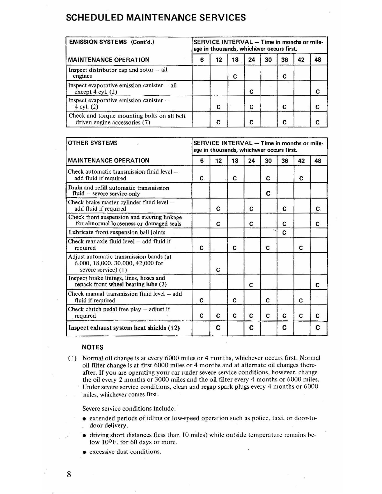
SCHEDULED
MAINTENANCE
SERVICES
EMISSION SYSTEMS (Cont'd.) SERVICE INTERVAL - Time
in
months
or
mile-
age
in thousands , whichever occurs
fint.
MAINTENANCE OPERATION 6
12
18
24
30 36
42
48
Inspect distributor cap and
rotor
- all
engines
C
C
Inspe ct evaporative emission canister
- a
ll
except 4 cyl, (2)
C C
Inspect evaporative emission canister
-
4 cyl, (2)
C C
C
C
Che
ck
and torque mounting
bolts on all belt
driven engine accessories
(7)
C C C C
OTHER SYSTEMS
SERVICE INTERVAL - Time in months
or
mile-
age
in
thousands, whichever occurs
first_
MAINTENANCE OPERATION
6 12
18
24
30 36
42
48
Check au tomatic transmission fluid
lev
el -
add fluid
if
required
C
C C C
Drain and
refill
autom
atic transmission
fluid
- severe service only
C
Check brake master cylinder fluid l
eve
l -
add fluid
if
required
C C C C
Check front suspension and steering linkage
f
or abn
ormal looseness
or
damaged seals
C C C C
Lubricate fro
nt
suspension ball joints
-.
C
Check rear axle fluid l
eve
l - add fluid
if
requir
ed
C
C C C
Adjust automatic
tr
ansmission bands (at
6,
000
, IS,OOO
, 30 ,
000, 42,000
for
severe
serVice)
(I
)
C
Inspe
ct
brake linings, lines, hoses and
repack front wheel bearing lube
(2)
C C
Check manual transmission fluid l
eve
l - add
flu
id
if
required
C C C
C
Check clutch pedal free play - adjust
if
required
C C
C C C
C
C C
Inspe
ct
exhaust
system
heat
shields
(12)
C C
C C
NOTES
(I)
N
ormal
oil
cha
nge is
at every
6000 miles or 4 months, whichever
occurs
first.
Normal
oil filter change
is
at
firs t
6000
miles
or 4 mont
hs
and
at
alternate
oil
changes there-
after
.
If
yo
u are
operating
your
car
und
er
severe service
cond
iti
ons, however
, change
the
oil every 2
months
or
3000
miles and the oil
filter
every 4
months
or
6000
mil es.
Under
severe service
conditions,
cle
an
and
regap
spar
k plugs
every 4 mon
ths
or
600
0
mil
es, whichever comes first.
8
Seve
re
servi
ce
conditions
includ
e:
• ex
tended
periods
of
idling
or
low-speed
operation sli
ch
as
police.
taxi.
or
door-t
o-
door
delivery .
• driving
short
distances
(less
than
10 miles) while
out
side
temperature
remains
be-
l
ow
100F.
fo r
60
days
or
more.
• excessive dust conditi
ons.
SCHEDULED MAINTENANCE SERVICES
NOTES
(Cont'd.)
(2) Adjust, repair
or
replace as required.
(3) Clean exhaust passages in EGR valve, carburetor spacer, and intake manifold.
(4)
If
coolant
is
dirty
or
rusty in appe'JFance, the system should be cleaned
and
the system
refIlled with the prescribed solution
of
Ford Cooling System Fluid and water.
(5) Drain and flush cooling system and replace cooling system fluid every
36,000 miles
or
36
months.
(6)
More
often
if
operated in severe dust conditions.
(7)
Check and torque
to
specifications.
(8)
If
replacement is
not
performed at 12,000
or
18,000 mile intelVals,
as
appropriate, re-
place complete plug set at time
of
plug malfunction.
(9) Check for function and replace
as
required.
(10)
With use
of
low lead
or
unleaded fuel.
(II)
With use
of
leaded fuel.
(12) Remove accumulated debris and inspect shields and attachments; repair or replace
as
required.
Perform each 6,000 miles for severe service usage over unpaved roads or off road applications.
EMISSION SYSTEM ABBREVIATIONS
PCV - Positive Crankcase Ventilation System
EGR - Exhaust Gas Recirculating System
TSP - Throttle Solenoid Positioner
9
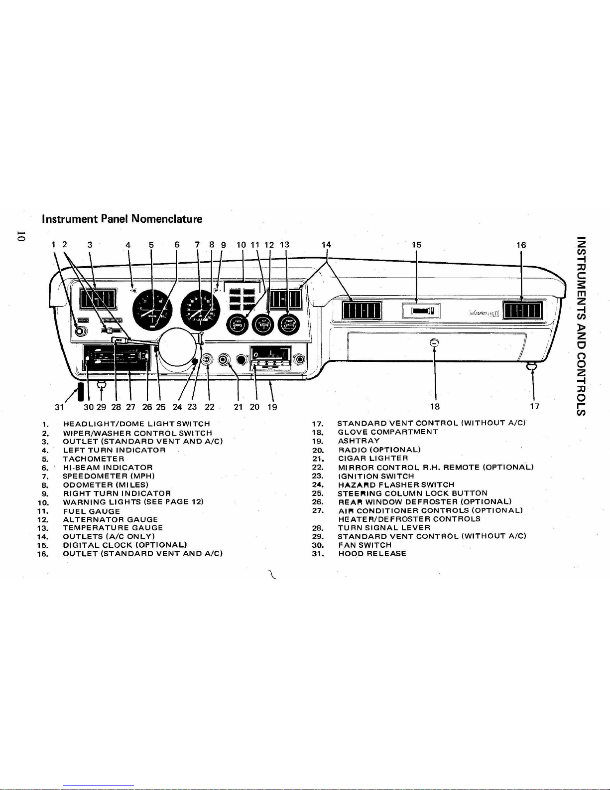
Instrument Panel Nomenclature
.....
o
1 2
3
4
5
6 7 8 9 10
11
12 13
14
15
16
Z
en
-I
::c
c:
S
m
Z
-I
en
»
z
c
n
0
z
-I
::c
0
31
30
29
28
27
26
25 24 23 22
21
20
19
18
17
r-
en
1.
HEADLIGHT/DOME
LIGHT
SWITCH
17.
STANDARD
VENT
CONTROL
(WITHOUT
A/C)
2.
WIPER/WASHER
CONTROL
SWITCH
1&
GLOVE COMPARTMENT
3.
OUTLET
(STANDARD
VENT
AND
A/C)
19.
ASHTRAY
4.
LEFT
TURN
INDICATOR
20.
RADIO
(OPTIONAL)
5.
TACHOMETER
21.
CIGAR
LIGHTER
6.
HI·BEAM
INDICATOR
22.
MIRROR
CONTROL
R.H.
REMOTE
(OPTIONAL)
7.
SPEEDOMETER
(MPH)
23.
IGNITION
SWITCH
8.
ODOMETER
(MILES)
24.
HAZAI'W
FLASHER
SWITCH
9.
RIGHT
TURN
INDICATOR
25.
STEE~ING
COLUMN
LOCK
BUTTON
10.
WARNING
LIGHTS
(SEE
PAGE
12)
26.
REA~
WINDOW
DEFROSTER
(OPTIONAL)
11.
FUEL
GAUGE
27.
AlP'!
CONDITIONER
CONTROLS
(OPTIONAL)
12.
ALTERNATOR
GAUGE
HEATER/DEFROSTER
CONTROLS
13.
TEMPERATURE
GAUGE
28.
TURN
SIGNAL
LEVER
14.
OUTLETS
(A/C
ON L Y)
29.
STANDARD
VENT
CONTROL
(WITHOUT
A/C)
15.
DIGITAL
CLOCK
(OPTIONAL)
30.
FAN
SWITCH
16.
OUTLET
(STANDARD
VENT
AND
A/C)
31.
HOOD
RELEASE
\.
INSTRUMENTS
AND
CONTROLS
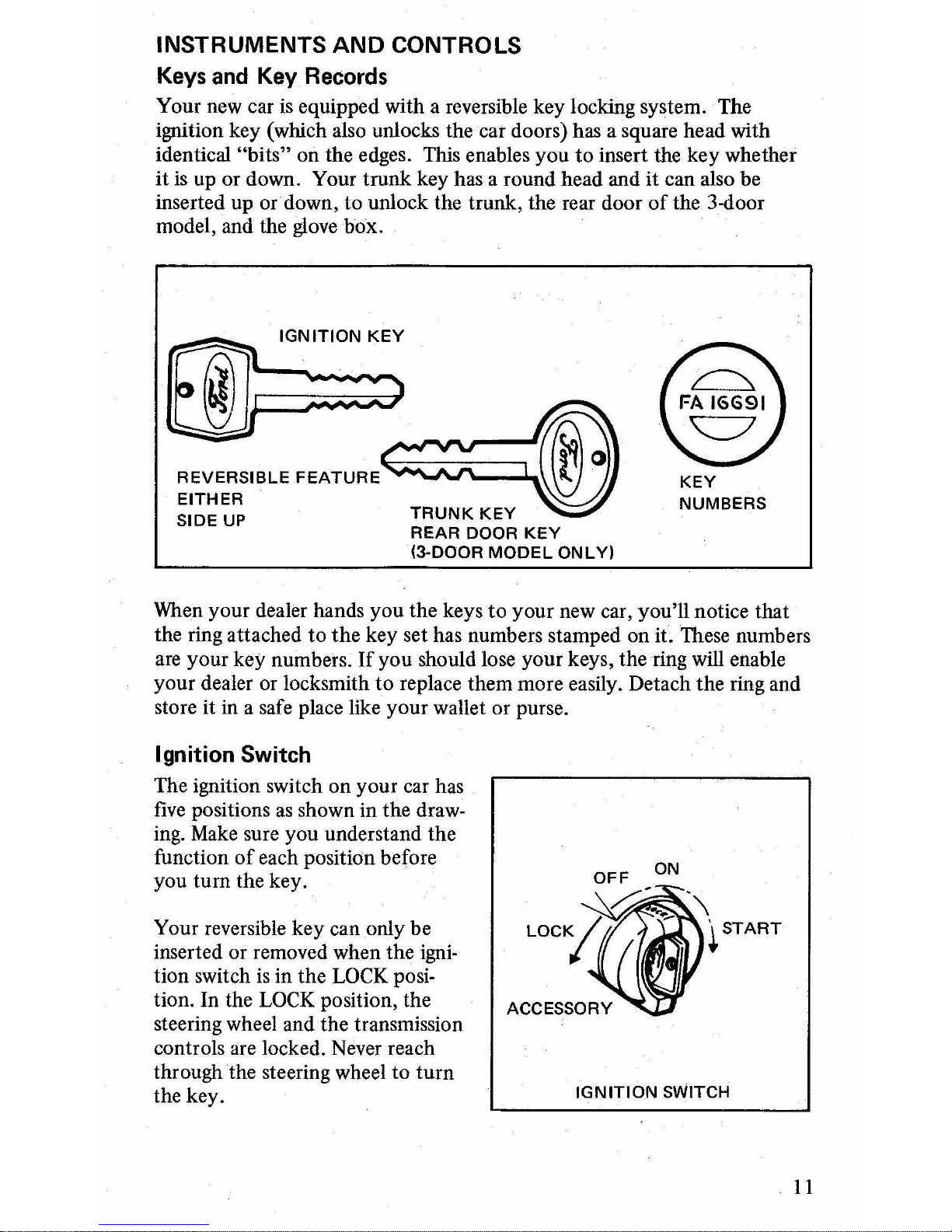
Keys
and
Key
Records
Your new car
is
equipped with a reversible key locking system. The
ignition key (which also unlocks the car doors) has a square head with
identical
"bits" on the edges. This enables you to insert the key whether
it
is
up or down. Your trunk key has a round head and it can also be
inserted up or down, to unlock the trunk, the rear door
of
the 3-door
model, and the
glove
box.
rn=;;
REVERSIBLE
FEATURE
~
EITHER
SIDE
UP
KEY
NUMBERS
When
your dealer hands you the keys
to
your new car, you'll notice that
the ring attached to
the
key set has numbers stamped on it. These numbers
are
your key numbers.
If
you should lose your keys, the ring will enable
your dealer or locksmith
to
replace them more easily. Detach the ring and
store it
in
a safe place like your wallet or purse.
Ignition Switch
The ignition switch on your car has
five
positions
as
shown in the draw-
ing.
Make
sure you understand the
function
of
each position before
you
tum
the key.
Your reversible key can only be
inserted or removed when the
igni-
tion switch
is
in the LOCK posi-
tion. In the
LOCK
position, the
steering wheel and the transmission
controls are locked. Never reach
through the steering wheel to
turn
the key.
~
O~_:N.\
LOCK~
~
~
START
ACCESSORY
IGNITION
SWITCH
11

INSTRUMENTS
AND
CONTROLS
In the
OFF
position, the steering wheel can be turned and the trans-
mission
is
unlocked. After the engine has been started,
the
OFF position
can be used
to
shut the engine down without locking
the
steering column
or the transmission.
Mter
you
have adjusted
the
seat, shoulder belts and mirrors, turn the key
to
the ON position. Turning the key
to
ON does
not
start
the engine.
Your purpose
in
turning
to
ONis
to
supply electrical current
to
the
igni-
tion system so
you
can check the 'various warning lights and gauges
as
outlined in this manual. When you're ready
to
start the engine make sure
the shift lever Is in P (PARK)
or
N (NEUTRAL) and tUfllthe key
to
the
START position.
For
cars with manual transmission, the clutch must be
depressed before turning
the
key
to
start,
as
the engine can be started in
any shift position.
CAUTION-Before you turn the key
to
ACe
(ACCESSORy)
or
LOCK,
the shift lever must be in P (PARK) for cars equipped with automatic
transmission and N (NEUTRAL) for cars equipped with a manual trans-
mission.
In
START, there are more warning system lights you should check before
the car starts. While in START, the engine will crarik until
you
release
the
key. The key then returns
to
ON, which is the normal running position.
Ignition Buzzer
To remove the ignition key after driving, the ignition switch must be in the
LOCK position. A warning buzzer sounds
if
you open the driver's door
with the key still in the ignition switch. The buzzer
is
to
remind
you
not
to
leave
your
keys in
the
car.
Steering Column Lock Button
Before you can turn key
to
ACC
(ACCESSORy)
or
LOCK,
you
must push
the steering column lock
button
on
the left side
of
the steering column.
In
ACC
you
can use the electrical equipment
on
your car without the engine
running or electricity flowing in
the
ignition circuit.
WARNING INDICATORS
Warning Lights and Buzzers
The following lights are located
on
the instrument panel and should all
glow when
you
turn the ignition key
to
the ON position. This indicates
that
the electrical circuits are functioningproperiy.
If
any
of
these
warning lights do
not
glow
as
indicated below, have your car's electrical
system checked
as
soon
as
possible.
12
INSTRUMENTS AND CONTROLS
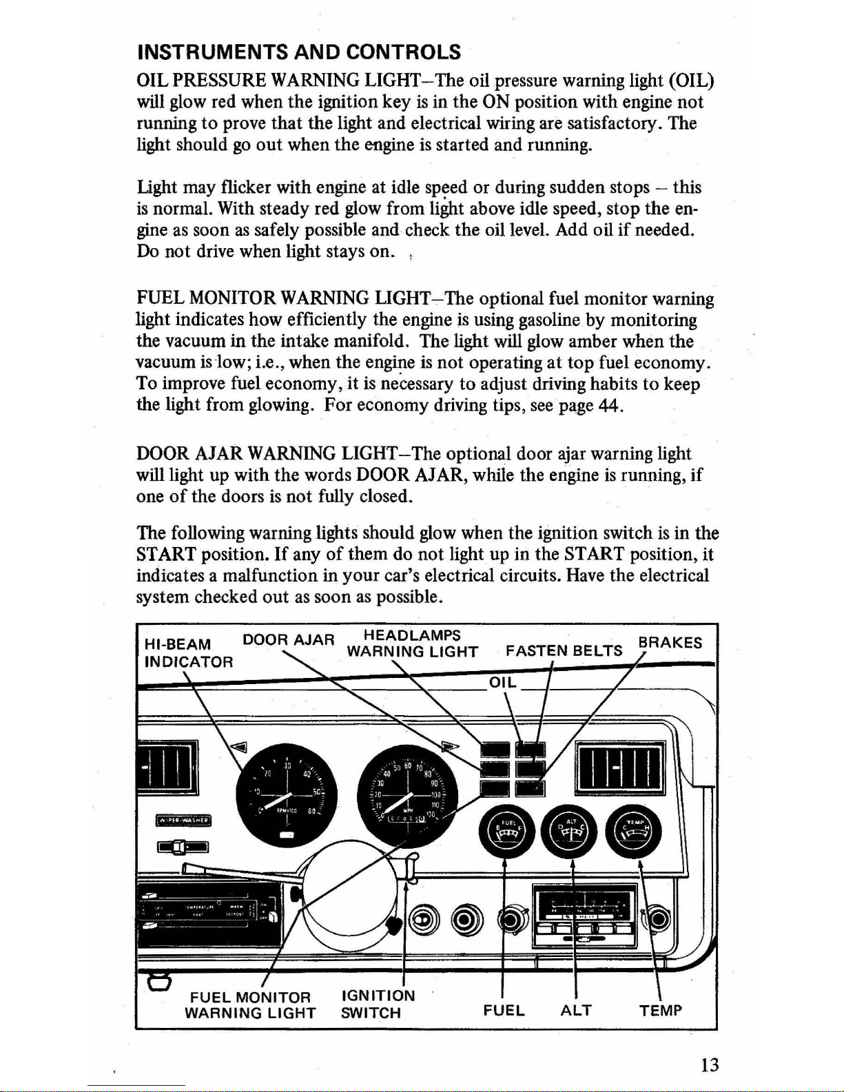
OIL PRESSURE WARNING LIGHT-The oil pressure warning light (OIL)
will glow red when the ignition key
is
in the ON position with engine
not
running
to
prove
that
the light and electrical wiring are satisfactory. The
light should
go
out
when the engine
is
started and running.
Ught
may flicker with engine at idle speed or during sudden stops - this
is
normal. With steady red glow from
li~t
above idle speed, stop the
en-
gine
as
soon
as
safely possible and check the oil level. Add oil
if
needed.
Do
not drive when light stays on. ,
FUEL MONITOR WARNING
LIGHT..,..The
optional fuel monitor warning
light indicates how efficiently the engine
is
using gasoline by monitoring
the vacuum in the intake manifold. The light will glow amber when the
vacuum islow; i.e., when the engine
is
not
operating
at
top
fuel economy.
To improve fuel economy, it is necessary to adjust driving habits
to
keep
the light from glowing. For economy driving tips,
seep~ge
44.
DOOR AJAR WARNING LIGHT-The optional door ajar warning light
will light up with the words
DOOR AJAR, while the engine
is
running,
if
one
of
the doors
is
not fully closed.
The following warning lights should glow when the ignition switch
is
in the
START position.
If
any
of
them do
not
light up in the START position, it
indicates a malfunction in
your car's electrical circuits. Have the electrical
system checked
out
as
soon
as
possible.
IGNITION
SWITCH
FUEL
ALT
TEMP
13

INSTRUMENTS AND CONTROLS
BRAKE SYSTEM WARNING
LIGHT-A
dual master cylinder
is
used in
the brake system. In case
of
a loss
of
hydraulic pressure in either the front
or rear brakes, a BRAKE warning light on the instrument panel
will
light
up upon application
of
the brakes. Any indicated malfunction in the
hydraulic braking system should receive immediate attention.
Your
optional parking brake warning light glows with the word BRAKE when
your parking brake
is
not
released and your ignition key
is
in any position
except
OFF or LOCK.
FASTEN BELTS WARNING LIGHT AND BUZZER-Your new car
features a starter interlock system, a seat belt warning system, and a threepoint lap-shoulder belt system for front seat positions. Refer to Safety
Restraint Systems.
This warning light glows and a buzzer sounds when the ignition switch
is
turned to the START position and a front seat occupant
is
unbuckled. The
light and buzzer also come
on
if a front seat occupant
is
unbuckled when
the ignition switch
is
in the
ON
position and the transmission is out
of
P (PARK) for automatic transmission
or
N (NEUTRAL) for manual
transmission.
"HEAD
LAMPS
ON" WARNING LIGHT AND BUZZER-This optional
warning light will illuminate and the buzzer will sound if
you
open the
driver's door while your headlights are on.
Warning
Gauges
The temperature gauge (TEMP) indicates the temperature
of
the engine
coolant. During normal operation, the pointer will move
to
the center
of
the dial, or under some conditions may move
as
far
as
the very
top
of
the
normal band. Unless the pointer moves
all
the way
to
the
hot
(H) position
at the far right
of
the dial, there
is
no danger to the engine from overheat-
ing.
If
it does, stop the engine and let it cool. Check the coolant level
(page 54), following the instructions concerning removing the filler cap.
If
the coolant
is
low, add coolant gradually, with the engine running.
If
the engine continues
to
overheat, do
not
drive the vehicle.
Have
the cool-
ing system checked and repaired.
FUEL GAUGE-The fuel gauge operates whenever the ignition key
is
in
the
ON
or ACCESSORY positions.
It
is
a good idea to keep the
gas
tank
over half full
at
all times to help minimize excessive condensation in the
tank.
NOTE-With the extra capacity fuel tank (V-8) and the optional extra capacity fuel tank (4 and 6 Cyl.), the fuel gauge will indicate full until the addi-
tional capacity has been used.
14

INSTRUMENTS
AND
CONTROLS
ALTERNATOR GAUGE-This
gauge
(ALT) shows the amount the battery
is
being charged
or
discharged. When electrical equipment
is
being operated
with the engine stopped or at slow idle, the gauge needle
may move toward
D
to
indicate discharge. At fast idle or driving speed, the needle should
move toward
C to indicate charge. When the battery
is
fully charged and
the alternator
is
generating enough power
to
supply the system loads, the
needle will remain slightly on the
C side
of
center.
In
normal driving,
if
the needle
is
on the D side
of
cent(}r
or indicating a high charge rate, the
charging system needs attention.
Windshield Wipers and
Washers
Panel Mounted
Windshield Wipers
To turn
on
the two-speed wipers,
slide the
WIPE-WASH
control
lever from left
to
right. The first
position
is
low speed; the second
is high speed.
Windshield Washers
WIPE·WASH
•
:I
To use the washers, push in the control lever . The wipers will start up on
low speed
as
the spray begins. For a constant spray, keep the control
lever pressed in. When
you
release the lever, the washers will stop and the
wipers will remain on low speed. When the windshield
is
wiped clean,
slide the control lever
off
(right to left).
Column
Mounted
r-------------,
Windshield Wipers
To
turn
on
the two-speed wipers
push the slide switch
ort the turn
sig-
nal arm
to
the right. The first posi-
tion is low speed; the second
is
high
speed.
Windshield Washers
WINDSHIELD
WASHER
BUTTON
To use the washers, push in on the
button
on
the end
of
the
turn
signal
arm.
Since·the
button
is
coupled to the slide switch, the windshield wipers
will automatically turn
on
at low speed.
For
a constant spray, keep the
button
pressed in.
Periodically check the windshield washer solvent reservoir and refill
as
necessary with windshield washer solvent. In freezing weather, do
not
use the windshield washers without first using the defroster to warm the
windshield.
CAUTION-Do
npt
manually move the wiper arms across the windshield,
or
you
will damage the wiper arms and pivots.
15
INSTRUMENTS
AND
CONTROLS
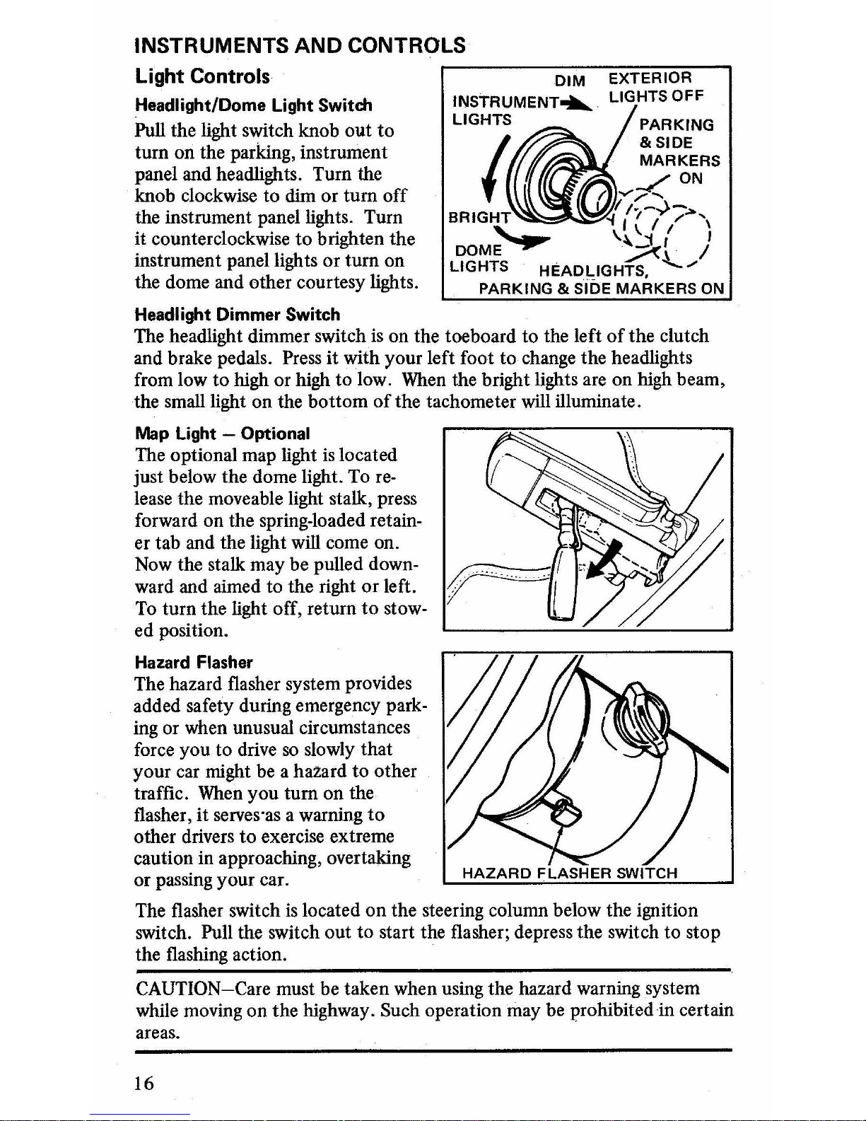
Light Controls
Headlight/Dome
Light
Switch
Pull the light switch knob out
to
turn on the parking, instrument
panel and headlights. Turn the
knob clockwise to dim or turn
off
the instrument panel lights. Turn
it counterclockwise
to
brighten the
instrument panel lights or turn on
the dome and other courtesy lights.
Headlight
Dimmer
Switch
EXTERIOR
LIGHTS OFF
PARKING
& SIDE
MARKERS
-/ON
(a
""/-..
I 'I
.-
-
BRIGHT
~
I(
..)
/>,
"--_
"
\.
I I 1
DOME
-,...--
.~t
/
LIGHTS HEADLIGHTS,
'-./
PARKING & SIDE MARKERS
ON
The headlight dimmer switch
is
on the toeboard to the left
of
the clutch
and brake pedals.
Press it with your left foot
to
change the headlights
from low to high or high
to
low. When the bright lights are on high beam,
the small light on the bottom
of
the tachometer will illuminate.
Map
Light
- Optional
The optional map light
is
located
just below the dome light. To
release the moveable light stalk, press
forward on the spring-loaded retainer tab and the light will come on.
Now the stalk may be pulled downward and aimed to the right
or
left.
To
turn the light off, return
to
stow-
ed position.
Hazard
Flasher
The hazard flasher system provides
added safety during emergency parking or when unusual circumstances
force you to drive
so
slowly that
your car might be a hazard to other
traffic. When you turn on the
flasher, it serves
'as a warning
to
other drivers
to
exercise extreme
caution
in
approaching, overtaking
or passing your car.
The flasher switch
is
located
on
the steering column below the ignition
switch.
Pull the switch out
to
start the flasher; depress the switch to stop
the flashing action.
CAUTION-Care must be taken when using the hazard warning system
while moving on the highway. Such operation may be prohibited
in
certain
areas.
16

INSTRUMENTS
AND
CONTROLS
Turn Signals
The
tum
signal lever
is
on
the left
side
of
the steering column. To
sig-
nal for a left
tum,
push the lever
down until it
is
held in position. To
signal for a right
tum,
pull the lever
up. When
you
signal for a
tum,
the
front parking light, the taillight, and
the indicator light
on
the instrument
panel will flash
on
and
off
on
the
left
or
right side
of
your car.
The lever will return
to
the
center position
(tum
signals
oft)
automatically
once
you
complete your
tum,
unless the
tum
is very shallow.
If
the indi-
cator continues to flash after making a
tum,
manually return the lever
to
center position. When
you
want
to
change lanes,
you
can flash your
turn
indicators without putting the lever in the
"hold"
position
by
moving the
lever either
up
or down until the indicator flashes. When
you
release the
lever it will return
to
the
center position.
If
the
tum
indicator light
on
the instrument panel does
not
flash
or
remains
on
continuously when
you
signal a
tum,
the signaling system
is malfunctioning. Have this condition corrected
as
soon
as
possible,
making sure in the meantime
to
use the accepted hand signals
to
indicate
your driving intentions.
Climate Control
Heater
System
VENTI LA
TION-
The vent system
on
your
car allows fresh air
to
enter
through the floor ducts and/or the outboard instrument panel registers.
The controls for these vents are located
on
each side
ofthe
instrument
panel. The vents are closed when the controls are all
the
way in.
If
you
pull
the
controls
out
midway, most
of
the air will be directed through the
floor ducts, with some
of
it
going through the panel registers. Pull
the
vent
controls all the way
out
and the air will flow through the panel registers
only.
You can
then
adjust the panel registers for air direction,
by
tilting
the register
or
adjusting the vanes. The vanes can be closed
to
shut
off
the
air flow from a particular register.
HEATING-
To heat the car, move
the
temperature (upper) control lever
to
WARM, and the heater (lower) selector lever
to
HEAT. The fan will
automatically come
on
when
the
heater selector lever
is
moved from OFF.
Set
the fan switch to the desired fan speed, and
as
the car warms, adjust
the temperature control lever to a comfortable position:
17

INSTRUMENTS AND CONTROLS
For maximum heater performance the right and left vent knobs must be
pushed in
to
the OFF position.
TEMPERATURE CONTROL LEVER
HEATER
SELECTOR LEVER
DEFROSTING AND DEFOGGING-Move the temperature control lever
to
WARM,
and the heater selector lever to DEFROST. Set the fan switch
to
the
desiI;ed
fan speed for air flow toward the windshield. You can regulate
the distribution
of
air between the defroster and heater by positioning the
heater selector lever between HEAT and DEFROST.
For defogging, set the controls
as
described above, with the fan at high
speed. When the windshield starts clearing, reduce the fan speed and move
the temperature control lever
to
a more comfortable position.
HEATING
AND
DEFROSTING
TIP-You
can improve heater and defrost-
er efficiency and reduce the possibility
of
fog forming
on
the inside
of
the
windshield by removing any snow or ice from the air intake below the
wind-
shield
on
the outside
of
the car.
Electric Rear Window Defroster
The optional rear window defroster
is designed to clear frost or fog from
the interior and exterior
of
the win-
dow. The control switch for this
de-
froster
is
located on the instrument
panel, on the right side
of
the heater-
air conditioning control.
To operate the rear defroster,
nrst
start the car engine, then push the
control switch up and release it. The
switch
will
return to the center posi-
tion and remain there while the defroster
is
operating. An indicator light
near the control switch lights up while the system
is
on.
If
there
is
a heavy
accumulation
of
snow on the rear window, brush it
off
to aid the defrost-
er in clearing frost from the window.
Turn
off
the rear defroster by push-
ing the control switch down and releasing it, or by turning
off
the ignition.
18
INSTRUMENTS AND CONTROLS
WARNING-Do
not
use scrapers or any
other
sharp instruments,
or
win-
dow cleaners containing abrasives
on
the interior surface
of
the rear window
or
the electrical conductors may be damaged.
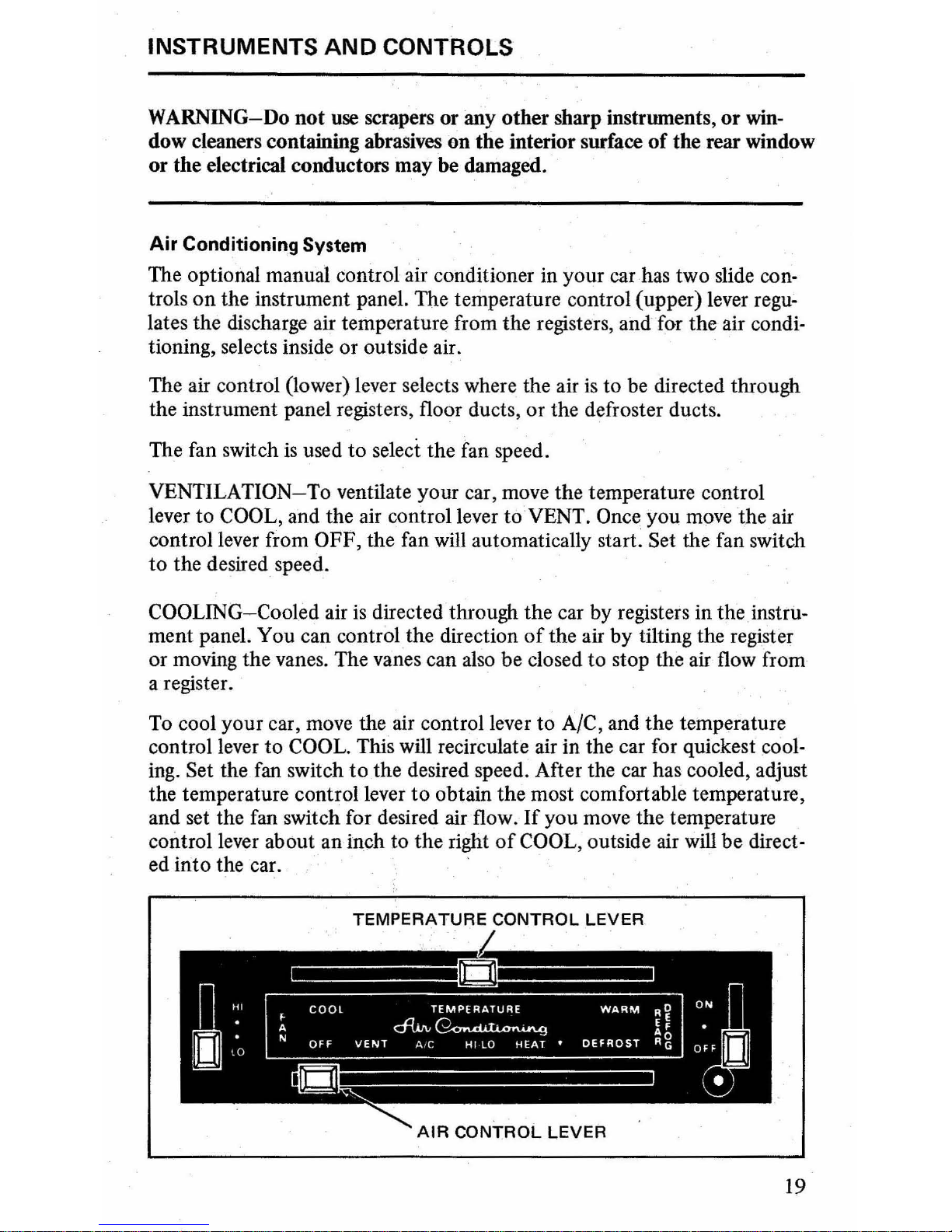
Air Conditioning System
The optional manual control air conditioner in your car has two slide controls
on
the instrument panel. The temperature control (upper) lever regu-
lates the discharge air temperature from the registers,
and
for the air condi-
tioning, selects inside or outside air.
The air control (lower) lever selects where the air
is
to
be directed through
the instrument panel registers, floor ducts, or the defroster ducts.
The fan switch
is
used
to
select the fan speed.
VENTILATION-To ventilate your car, move the temperature control
lever
to
COOL, and the air control lever
to
VENT. Once you move the air
control lever from
OFF, the fan will automatically start. Set the fan switch
to
the desired speed.
COOLING-Cooled air
is
directed through the car by registers in
theinstru-
ment panel. You can control the direction
of
the air
by
tilting the register
or moving the vanes. The
vanes can also be closed
to
stop the air flow from
a register.
To cool
your
car, move the air control lever
to
A/C, and
the
temperature
control lever
to
COOL. This will recirculate air in the car for quickest cool-
ing. Set the fan switch
to
the desired speed. After the car has cooled, adjust
the temperature control lever
to
obtain
the
most comfortable temperature,
and set the fan switch for desired air flow.
If
you move the temperature
control lever about an inch
to
the
right
of
COOL, outside air will
be
direct-
ed
into
the car. '
TEMPERATURE CONTROL LEVER
19

INSTRUMENTS AND CONTROLS
During operation with the air control lever in A/C,
it
is
normal for frost to
build up on the air conditioner lines and components in the engine compartment.
Since the air conditioner removes moisture from the air during
operation, water may drip on the pavement under the air conditioner after
you have stopped your car.
AIRCONDITIONING
TIPS-If
your
cllr
has been parked with the windows
closed during
hot
weather (especially under a direct sun), the air condition-
er will do a much faster job
of
cooling jf you will drive for two or three
minutes with all the windows open. This will force most
of
the warm air
out
of
the
car. Then, close the windows and operate the air conditioner in
the regular way.
When
stopped in traffic for long periods
of
time in hot weather, place the
automatic transmission lever in P (PARK) or N (NEUTRAL) to increase
the engine idle speed. This aids
iIi
engine cooling and air conditioner
efficiency.
HEA
TING-
To heat your car, move the temperature control lever to
WARM,
and the air control lever to either HEAT or HI-LO. The HEAT
position directs
air through the floor ducts, with a small amount going
through the defrosters. The
HI-LO position directs air through both, the
floor ducts and the instrument panel registers.
Set the fan switch to the
desired speed for the required amount
of
air flow, and
as
the car warms,
adjust the temperature control lever for maximum comfort.
DEFROSTING
AND
DEFOGGING-To defrost the windshield, move the
temperature control lever between
COOL and
WARM,
and the
air
control
lever to HEAT.
Set the fan switch
to
the highest speed and run the system
for approximately
30
seconds. This will reduce chances
of
fog
forming on
the inside
of
the windshield. After the
30
seconds, move the air control
lever
to
DEFROST, the temperature control lever to
WARM,
and
all
the
air flow will be directed toward the windshield. You can split the air flow
between the defrosters and the floor ducts by setting the air control lever
at a position between HEAT and
DEFROST.
You can use the air conditioning system to defog the side windows in
mild weather.
Set the temperature control lever to COOL, the air control
lever
to
A/C, and the fan switch to a high speed. Rotate the instrument
panel registers
to
direct the air flow towards the windows.
HEATING AND
DEFROSTING
TIP-You
can improve heater and defrost-
er
effiCiency and reduce the chances
of
fog forming
on
the inside
of
the
windshield by removing any snow or ice from
the
air intake below the
windshield on the outside
of
the car.
20
INSTRUMENTS AND CONTROLS
Radios
AM
Push Button Tuning
To set the five push
buttons
for
AM
broadcasting
on
your radio, follow the
directions below.
If
the radio is equipped with an AM/FM band selector bar, be sure it
is in the
AM
position.
Turn your radio on.
Allow the
radio about
five
minutes
to
warm up.
· Pull the push
button
to
be set
out
until it stops.
Tune in the desired station with the manual tuning knob.
· Push the
button
all the way in and release it.
· Repeat for the remaining buttons.
FM
and FM/Stereo Tuning
FM
and FM/stereo broadcasts have some characteristics
Which
do not ap-
pear in
AM
broadcasting. These conditions are not due
to
any fault
in
your
car radio.
The effective range
of
FM
and FM/stereo broadcasts
is
about
20
miles.
When driving away from a station, you may have to fine-tune the radio
and
turn
up the volume
as
the station becomes weaker. When the
hiSSing
or popping noise (which indicates a weak broadcast signal) becomes too
strong, tune to another station .
Tall buildings, hills, or depressed roadways may cause garbled or weak reception or even temporary loss
of
the program.
When
you pass near the broadcasting tower
of
an
FM
station, that station
may
cut
out
another station
to
which you
are
listening even though you
haven't changed your
dial setting. The
two
stations may even switch back
and forth several times until you move a little farther away from the tower.
FM
Push Button Tuning
To set the
five
push buttons for
FM
or FM/stereo broadcasting, follow the
directions below.
· Turn the radio on.
· Allow the radio about five minutes
to
warm up.
·
Be
sure the band selector
is
in the
FM
position.
· Pull
the
push
button
out
until
it
stops.
· Tune in the desired station with
the
manual tuning knob.
· Push the
button
all the way
in
and release it.
· Repeat for the remaining buttons.
AM
Radio Operation
To operate the optional
AM
radio, follow these instructions:
21

INSTRUMENTS AND CONTROLS
OFF-ON
KNOB
, VOLUME CONTROL-You can play the
AM
radio when
the ignition switch
is
in either the
ON
or
ACC
position. To
turn
it on , turn
the off-on knob, located on the left side
of
the radio, clockwise.
By
con-
tinuing
to
turn the knob in the same direction, you
will
increase the volume.
AM
RADIO
OFF/ON & VOLUME
CONTROL
STATION
SELECTOR
BUTTONS
TONE CONTROL-The tone control
is
the ring knob located right behind
the off-on knob. Turning the tone control clockwise
will
increase the treble
range while turning it counterclockwise will increase the bass range.
STATION SELECTION- You can select the radio station you want by
turning the manual tuning knob, located
on
the right side
of
the radio. Or
you can
use
the push buttons which can be pre-set to
five
stations
of
your
choice.
AM/FM
Monaural Radio Operation
To operate the optional AM/FM Monaural radio, follow the instructions
below
. .
OFF-ON KNOB, VOLUME CONTROL-You
can play the radio when the
ignition switch
is
in the
ACC
or
ON
position. To
tum
it
on, turn the off-
on knob, located on the left side
of
the radio ,
in
a clockwise direction.
By
continuing to turn the knob in the same direction , you will increase the
volume.
TONE CONTROL-The tone control
is
the ring knob located right behind
the off-on knob. Turning the tone control clockwise will increase the treble
range while turning it counterclockwise
will
increase the bass range.
BAND
SELECTOR
BAR-The
band selector bar allows you to select either
AM
or
FM
broadcasting. Slide the bar, located just below the numbered
scale, to the left for
AM
operation. Slide it to the right for
FM
operation.
22
INSTRUMENTS
AND
CONTROLS
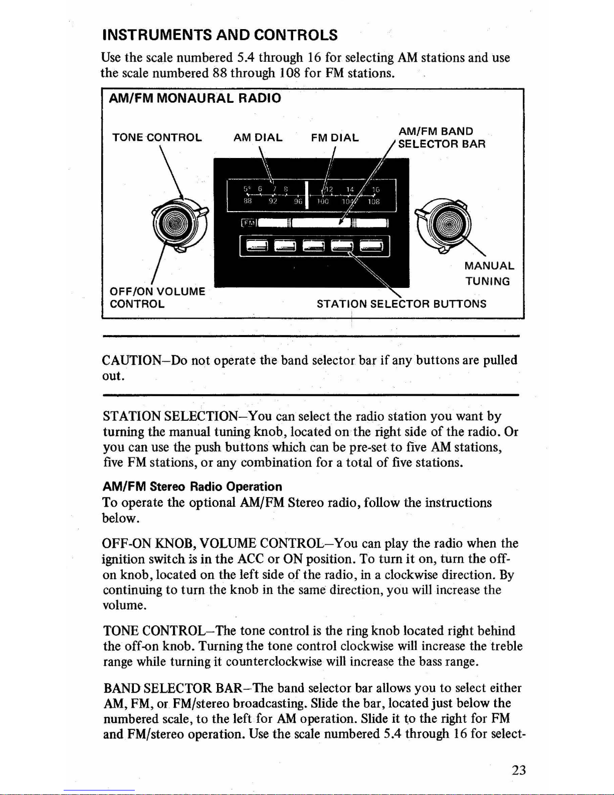
Use
the scale numbered 5.4 through
16
for selecting
AM
stations and use
the scale numbered
88 through 108 for
FM
stations.
AM/FM
MONAURAL
RADIO
STATION
SELECTOR BUTTONS
CAUTION-Do not operate the band selector bar if any buttons are pulled
out.
STATION SELECTION-You can select the radio station you want by
turning the manual tuning knob, located
on
the right side
of
the radio. Or
you can use the push buttons which can be pre-set to
five
AM
stations,
five
FM
stations,
or
any combination for a total
of
five
stations.
AM/FM Stereo Radio Operation
To operate the optional AM/FM Stereo radio, follow the instructions
below.
OFF-ON KNOB, VOLUME CONTROL-You can play the radio when the
ignition switch
is
in
the
ACC
or
ON
position. To
tum
it
on,
tum
the off-
on knob, located on the left side
of
the radio,
in
a clockwise direction.
By
continuing to
tum
the knob in the same direction, you
will
increase the
volume.
TONE CONTROL-The tone control
is
the ring knob located right behind
the off-on knob. Turning the tone control clockwise
will
increase the treble
range while turning it counterclockwise
will
increase the bass range.
BAND
SELECTOR BAR-The band selector bar allows you to select either
AM,
FM, or FM/stereo broadcasting. Slide the bar, located just below the
numbered scale,
to
the left for
AM
operation. Slide it to the right for
FM
and FM/stereo operation.
Use
the scale numbered 5.4 through
16
for select-
23
INSTRUMENTS
AND
CONTROLS
ing
AM
stations and use the scale numbered 88 through 108 for
FM
and
FM/stereo stations.
CAUTION-Do
not
operate the band selector bar
if
any push
buttons
are
pulled out.
STATION SELECTION-You can select the radio station
you
want
by
turning the manual tuning knob, located
on
the right side
of
the radio.
Or
you
can use the push
buttons
which can be pre-set
to
five
AM
stations
and
five
FM
or FM/stereo stations
of
your choice, for a total
of
ten
stations.
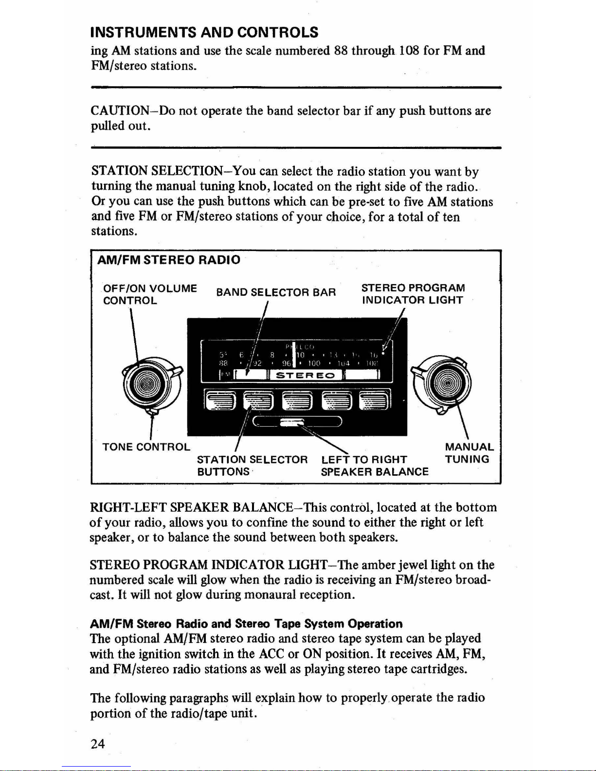
AM/FM
STEREO RADIO
TONE
CONTROL
BAND
SELECTOR
BAR
STATION
SELECTOR
BUTTONS ·
RIGHT-LEFT SPEAKER BALANCE-This control, located at
the
bottom
of
your radio, allows
you
to
confine the sound
to
either the right
or
left
speaker, or
to
balance the sound between
both
speakers.
STEREO PROGRAM INDICATOR
LIGHT-The
amber jewel light
on
the
numbered scale will glow when the radio is receiving
an
FM/stereo broad-
cast.
It
will not glow during monaural reception.
AM/FM Stereo Radio and Stereo Tape System Operation
The optional AM/FM stereo radio and stereo tape system can
be
played
with the ignition switch
in the
ACC
or ON position.
It
receives
AM,
FM,
and FM/stereo radio stations as well
as
playing stereo tape cartridges.
The
follOwing paragraphs will explain
how
to
propedyoperate
the radio
portion
of
the radio/tape unit. .
24

INSTRUMENTS
AND
CONTROLS
OFF-ON KNOB AND VOLUME CONTROL-The knob which turns the
radio
on
and controls its volume is found
on
the left side
of
the radio. Ro-
tate the knob clockwise
to
turn the radio on and continue turning it in
that direction
to
increase the volume. You will also have to pull the tape
cartridge from the tape slot about one inch
or
else remove it completely.
This automatically switches the radio
on
and the tape system off.
BAND
SELECTOR BUTTON-The band selector
button
is
located
on
the
right side
of
the numbered scale. Operate the
button
to
select either
AM
or
FM
broadcasts.
CAUTION-Never slide the
AM
or
FM
band selector switch when one
of
the tuning push buttons
is
pulled out.
Use
the scale numbered 5.4 through 16 for
AM
broadcasts and the scale
numbered 88 through
108
for
FM
and FM/stereo broadcasts.
TUNlNG-
To select the station you want, either
tum
the manual tuning
knob, found on the right side
of
the radio, or use the push buttons. The
five
push buttons can be set
to
five
AM
stations,
five
FM or FM/stereo
stations, or any combination for a total
of
five
stations.
TONE CONTROL-The tone control is located behind the off-on knob
and the volume control. Turn the control clockwise to increase treble tones
and decrease bass tones; turn the control counterclockwise
to
do the
opposite.
STEREO PROGRAM INDICATOR LIGHT-The amber jewel light
on
the
radio scale
will glow when the radio
is
receiving FM/stereo broadcasts.
The light will not glow during monaural broadcasts.
TAPE PLAYER
PORTION-The following paragraphs explain how to
properly operate the tape portion
of
the radio/tape unit.
To operate the tape system
on
the radio, turn the radio
on
and insert
the open end
of
the
tape cartridge, label side up, into the tape slot. Make
sure the cartridge
is
firmly installed.
During extremely cold weather, the tape system may take a few minutes
to warm up.
25
 Loading...