

Ford Comet 1966, 1966 Mustang, 1966 Fairlane, 1966 Falcon, 1966 Comet Shop Manual
Copyright © 2006, Forel Publishing Company, LLC, Woodbridge, Virginia
All Rights Reserved. No part of this book may be used or reproduced in any manner
whatsoever without written permission of Forel Publishing Company, LLC. For
information write to Forel Publishing Company, LLC, 3999 Peregrine Ridge Ct.,
Woodbridge, VA 22192
1966 Comet, Falcon, Fairlane and Mustang Shop Manual
ISBN: 0-9673211-3-1
EAN: 978-0-9673211-3-4
Forel Publishing Company, LLC
3999 Peregrine Ridge Ct.
Woodbridge, VA 22192
This publication contains material that is reproduced and distributed under a
license from Ford Motor Company. No further reproduction or distribution of the
Ford Motor Company material is allowed without the express written permission
of Ford Motor Company.
Disclaimer
Although every effort was made to ensure the accuracy of this book, no representations or warranties of
any kind are made concerning the accuracy, completeness or suitability of the information, either expressed
or implied. As a result, the information contained within this book should be used as general information
only. The author and Forel Publishing Company, LLC shall have neither liability n or responsibility to any
person or entity with respect to any loss or damage caused, or alleged to be caused, directly or indirectly by
the information contained in this book. Further, the publisher and author are not engaged in rendering legal
or other professional services. If legal, mechanical, electrical, or other expert assistance is required, the
services of a competent professional should be sought.

GROUP INDEX
Vehicle
Suspension, Steering, Wheels and Tires
Drive
Manual Transmission
Automatic Transmission
Ignition System
Fuel System
Cooling System
Identification
Brakes
Rear Axle
Shaft
and Clutch
Engine
1
2
3
4
5
6
7
8
9
10
11
Exhaust System
Charging System
Starting System
Lighting System, Horns and Instruments
Ventilating, Heating, and Accessories
Body, Doors and Windows
Trim, Seats, and Convertible Tops
Maintenance Schedule
Maintenance Operations
Lubrication Chart
Schematics
12
13
14
15
16
17
18
19
20
21
22
SPECIFICATIONS AND SPECIAL SERVICE TOOLS
AT END OF EACH GROUP
This shop manual provides the Service Technician wlth complete information for the proper servicing of the
1966
Comet,
Falcon,
Fairlane and Mustang cars.
.
The information is grouped according -to the type of work
being performed, such as diagnosis and testing, frequently
performed adjustments and repairs, in-vehicle adjustments,
overhaul, etc. Specifications and recommended special tools
are included.
Refer to the opposite page for important vehicle identifica-
tion data.
The descriptions and specifications in this manual were in
eflect at the time this manual was approved for printing. The
Ford Motor Company reserves the right to discontinue models
at any time, or change specifications or design, without notice
and without incurring obligation.
SERVICE PUBLICATIONS
VEHICLE IDENTIFICATION
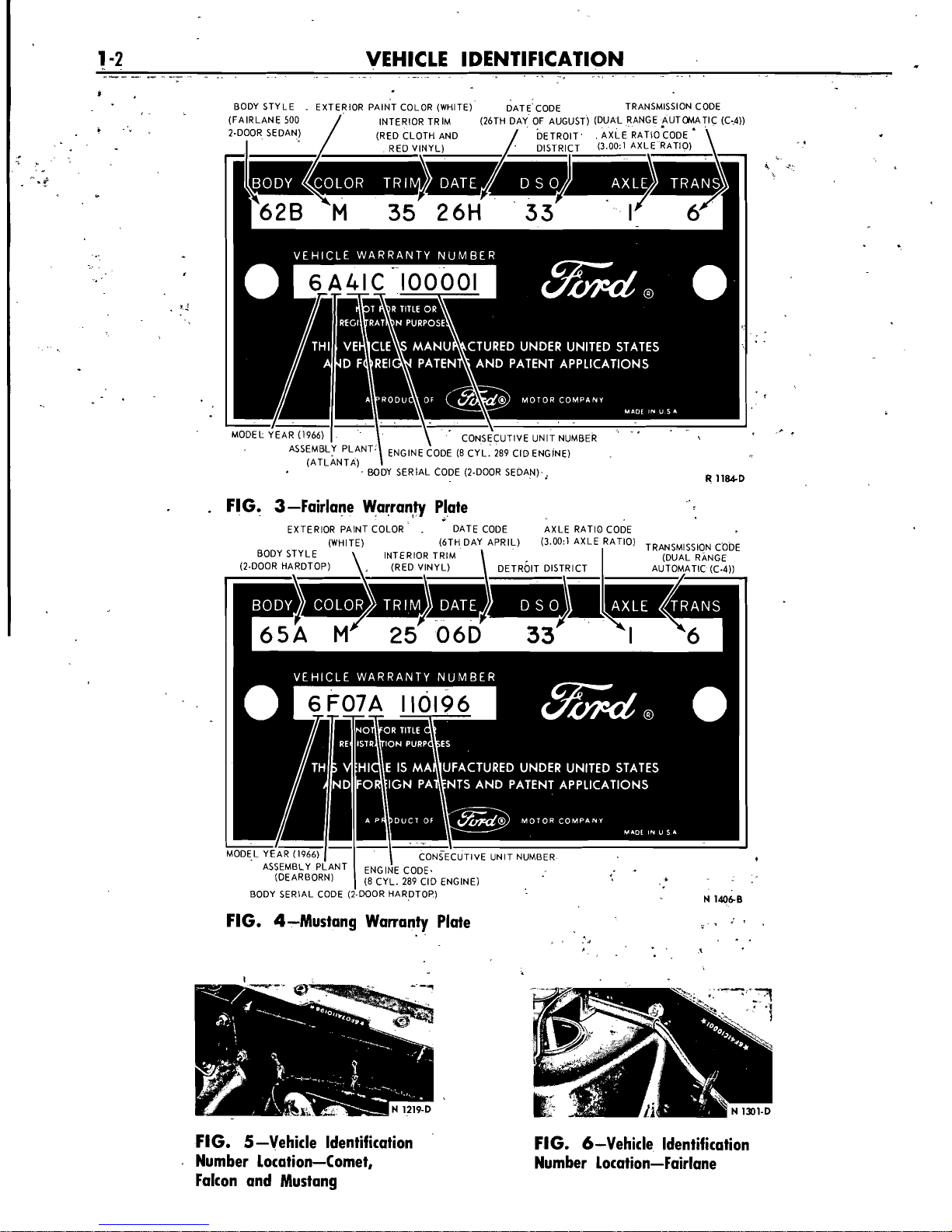
BODY STYLE . EXTERIOR PAINT COLOR (WHITE) DATE CODE TRANSMISSION CODE
(FAIRLANE 500
/
INTFRIOR TRIM (26TH DAY OF AUGUST) (DUAL RANGE AUTOMATIC (C-4))
.
/
2.DOOR SEDAN) (RED CLOTH AND
DETROIT
AXLE
RATIO;ODE
'
I
RED V!NYL)
DISTR~FT
(3.00:l AXLE RATIO)
C
/
MOOEL YEAR (1966)
1
I
.,
-
-
\
*
CONS~CUTIVE UNIT NUMBER
PLANT
ENGINE CODE (8 CYL. 289 CIO ENGINE)
(ATLANTA)
BODY SERIAL CODE (2-DOOR SEDAN)
,
R
1184.D
.
FIG. 3-Fairlane Wprranty Plate
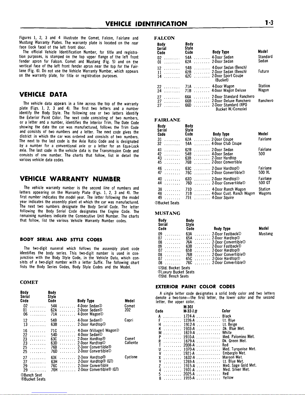
EXTERIOR PAINT COLOR
.
DATE CODE AXLE RATIO CODE
(WHITE)
(6TH DAY APRIL) (3.00:) AXLE RATIO)
CODE
BODY STYLE INTERIOR TRIM
\
(DUAL
RANGE
(2-DOOR HARDTOP)
,
(RED VINYL)
DETROIT
DISTRICT AUTOMATIC (C.4))
\-,-
I-
I
I
M0DE.L
Ashttps://manualmachine.com/~(~~-'cuTlvr
YEAR (1966) UNIT NUMBER
.
z
$
(8 CYL. 289 CIO ENGINE)
FIG. 4-Mustang Warranty Plate
.
I.
.
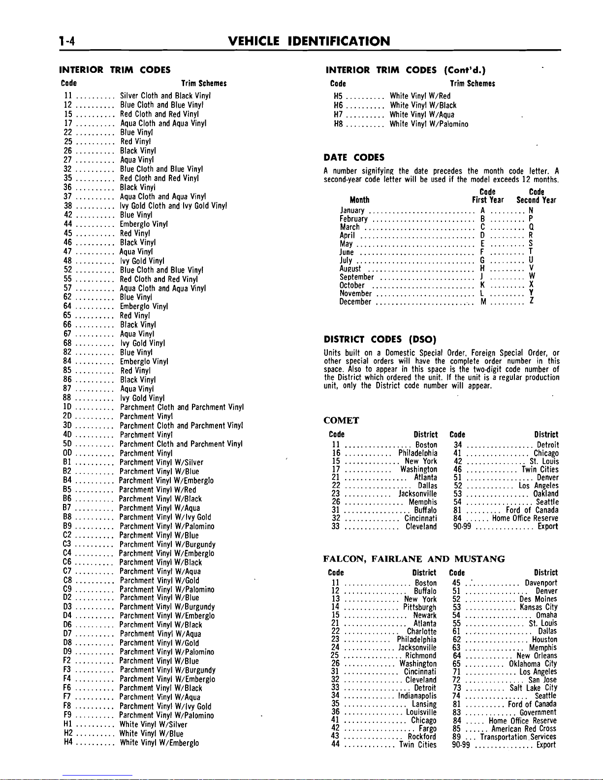
FIG. 5-Vehicle Identification
Number Location--Comet,
Falcon and Mustang
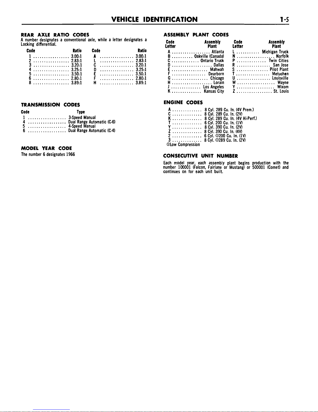
FIG. 6-Vehicle ldentification
Number Location-Fairlane
VEHICLE IDENTIFICATION
1
-3
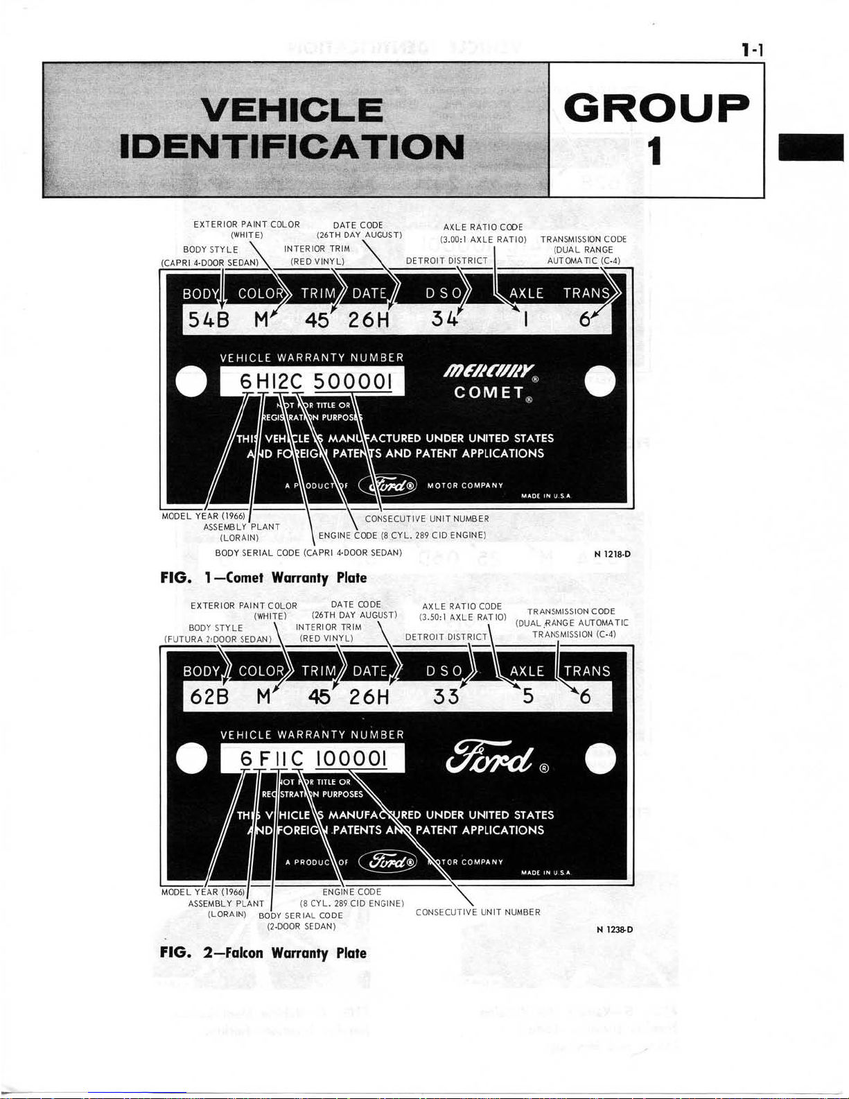
Figures 1, 2, 3 and 4 illustrate the Comet, Falcon, Fairlane and
Mustang Warranty Plates. The warranty plate is located on the rear
face (lock face) of the left front door.
The official Vehicle Identification Number, for title and registration purposes, is stamped on the top upper flange of the left front
fender apron for Falcon. Comet and Mustang (Fig.
5)
and on the
vertical face of the left front fender apron near the top for the
Fairlane (Fig. 6). Do not use the Vehicle Warranty Number, which appears
on the warranty plate, for title or registration purposes.
VEHICLE DATA
The vehicle data appears in a line across the top of the warranty
plate (Figs. 1, 2, 3 and 4). The first two letters and a number
identify the Body Style. The following one or two letters identify
the Exterior Paint Color. The next code consisting of two numbers,
or a letter and a number, identifies the Interior Trim. The Date Code
showing the date the car was manufactured, follows the Trim Code
and consists of two numbers and a letter. The next code gives the
district in which the car was ordered and consists of two numbers.
The next to the last code is the Axle Ratio Code and is designated
by a number for a conventional axle or a letter for an
Equa-Lock
axle. The last code in the vehicle data is the Transmission Code and
consists of one number. The charts that follow, list in detail the
various vehicle data codes.
VEHICLE WARRANTY NUMBER
The vehicle warranty number is the second line of numbers and
letters appearing on the Warranty Plate (Figs.
1,
2, 3 and 4). The
first number indicates the model year. The letter following the model
year indicates the assembly plant at which the car was manufactured.
The next two numbers designate the Body Serial Code. The letter
following the Body Serial Code designates the Engine Code. The
remaining numbers indicate the Consecutive Unit Number. The charts
that follow, list the various Vehicle Warranty Number codes.
BODY SERIAL AND STYLE CODES
The two-digit numeral which follows the assembly plant code
identifies the body series. This two-digit number is used in conjunction with the Body Style Code, in the Vehicle Data, which consists of a two-digit number with a letter Suffix. The following chart
lists the Body Series Codes, Body Style Codes and the Model.
FALCON
Body Body
Serial Style
Code Code Body Type
........
........
02 54A 4-Door Sedan
........
........
01 62A 2-Door Sedan
........
........
12 548 4-Door Sedan (Bench)
........
........
11 62B 2-Door Sedan (Bench) Futura
14
........
62C
........
2-Door Sport Coupe
(Bucket)
22
........
71A
........
&Door Wagon
Station
........
........
24 71B &Door Wagon Deluxe Wagon
........
........
27 66A 2-Door Standard Ranchero
........
27 66B
........
2-Door Deluxe Ranchero Ranchero
........
........
27 66D 2-Door Standard (RPO
Bucket W/Console)
FAIRLANE
Body Body
Ser~al Style
Code Code Body Type Model
31
........
62A
........
2-Door Coupe Fairlane
........
........
32 54A 4-Door Club Coupe
41
........
62B
........
2-Door Sedan Fairlane
42
........
548
........
4-Door Sedan 500
........
........
43 638 2-Door Hardtop,
........
........
45 76B 2-Door Convert~ble
........
........
46 63C 2-Door Hardtop@ Fairlane
........
........
47 76C
2-Door Convertible@ 500 XL
40
........
63D
........
2-Door Hardtop? Fairlane
........
........
44 76D 2-Door Convert~bleO 500 GT
........
........
38 71D 4-Door Ranch Wagon Station
........
........
48 718 4-Door Cust. Ranch Wagon Wagons
........
........
49 71E 4-D00r Squire
@Bucket Seats
MUSTANG
Body Body
Serial Style
Code Code Body Type Model
09
........
63A
........
2-Door Fastback@ Mustang
........
........
07 65A 2-Door Hardtop@
........
........
08 76A 2-Door Convertible@
09
........
638
........
2-Door Fastback@
07
........
65B
........
2-Door Hardtop@
........
........
08 76B 2-Door Convertible@
........
........
07 65C 2-Door Hardtop@
........
........
08 76C 2-Door Convertible@
OStd.
Bucket Seats
@Luxury Bucket Seats
BStd. Bench Seats
COMET
EXTERIOR PAINT COLOR CODES
Body Body
Serial Style
Code Code Body Type Model
02
........
54A
........
4-Door Sedan@ Comet
01
........
62A
........
2-Door Sedan@ 202
06
........
71A
........
4-Door Wagon@
12
........
548
........
&Door Sedan@ Capri
13
........
63B
........
2-Door Hardtop@
16
........
71C
........
&Door (Villager) Wagon3
22
........
54D
........
4-Door Sedan@
23
........
63C
........
2-Door Hardtop@ Comet
23
........
63D
........
2-Door Hardtop@ Caliente
25
........
76B
........
2-Door Convertible@
25
........
76D
........
2-Door Convertible@
27
........
63E
........
2-Door Hardtop Cyclone
........
27
........
63H 2-Door Hardtop@ (GT)
........
29
........
76C 2-Door Convertible
........
29
........
76H 2-Door Convertible@ (GT)
@Bench
Seat
@Bucket Seats
Model
Standard
Sedan
A single letter code designates a solid body color and two letters
denote a two-tone-the first letter, the lower color and the second
letter, the upper color.
M.301
Code M-32-I# Color
............
.........
A 1724-A Black
F
.........
1226-A
............
Lt. Blue
.........
............
H 1912-A Lt. Beige
............
.........
K
1903-A Dk. Blue Met.
............
.........
M 1619-A White
............
.........
P 1910-A Med. Palomino Met.
............
.........
R 1879-A Dk. Green Met.
............
.........
T 2008-A Red
............
.........
U
1070-A Med. Turquoise Met.
.........
............
V 1921-A Embernlo Met.
~aroon Met.
Lt. Blue Met.
Med. Sage Gold Met.
Med. Silver Met.
Red
Yellow
INTERIOR TRlM CODES
Code Trim Schemes
11
..........
Silver Cloth and Black Vinyl
12
..........
Blue Cloth and Blue Vinyl
15
..........
Red Cloth and Red Vinyl
..........
17 Aqua Cloth and Aqua Vinyl
22
..........
Blue Vinyl
25
..........
Red Vinyl
26
..........
Black Vinyl
27
..........
Aqua Vinyl
..........
32
Blue Cloth and Blue Vinyl
..........
35 Red Cloth and Red Vinyl
36
..........
Black Vinyl
..........
37 Aqua Cloth and Aqua Vinyl
38
..........
Ivy Gold Cloth and Ivy Gold Vinyl
42
..........
Blue Vinyl
44
..........
Emberglo Vinyl
45
..........
Red Vinyl
46
..........
Black Vinyl
47
..........
Aqua Vinyl
48
..........
Ivy Gold Vinyl
52
..........
Blue Cloth and Blue Vinyl
55
..........
Red Cloth and Red Vinyl
..........
57
Aqua Cloth and Aqua Vinyl
62
..........
Blue Vinyl
64
..........
Emberglo Vinyl
65
..........
Red Vinyl
66
..........
Black Vinyl
67
..........
Aqua Vinyl
68
..........
Ivy Gold Vinyl
82
..........
Blue Vinyl
84
..........
Emberglo Vinyl
85
..........
Red Vinyl
86
..........
Black Vinyl
87
..........
Aqua Vinyl
88
..........
Ivy Gold Vinyl
1D
..........
Parchment Cloth and Parchment Vinyl
2D
..........
Parchment Vinyl
..........
3D
Parchment Cloth and Parchment Vinyl
4D
..........
Parchment Vinyl
5D
..........
Parchment Cloth and Parchment Vinyl
OD
..........
Parchment Vinyl
B1
..........
Parchment Vinyl W/Silver
82
..........
Parchment Vinyl W/Blue
84
..........
Parchment Vinyl W/Emberglo
85
..........
Parchment Vinyl W/Red
B6
..........
Parchment Vinyl WIBlack
87
..........
Parchment Vinyl W/Aqua
B8
..........
Parchment Vinyl W/lvy Gold
B9
..........
Parchment Vinyl W/Palomino
C2
..........
Parchment Vinyl W/Blue
C3
..........
Parchment Vinyl W/Burgundy
C4
..........
Parchment Vinyl W/Emberglo
C6
..........
Parchment Vinyl W/Black
C7
..........
Parchment Vinyl W/Aqua
C8
..........
Parchment Vinyl W/Gold
C9
..........
Parchment Vinyl W/Palomino
D2
..........
Parchment Vinyl W/Blue
D3
..........
Parchment Vinyl W/Burgundy
D4
..........
Parchment Vinyl W/Emberglo
D6
..........
Parchment Vinyl W/Black
D7
..........
Parchment Vinyl W/Aqua
D8
..........
Parchment Vinyl W/Gold
D9
..........
Parchment Vinyl W/Palomino
F2
..........
Parchment Vinyl W/Blue
F3
..........
Parchment Vinyl W/Burgundy
F4
..........
Parchment Vinyl W/Emberglo
F6
..........
Parchment Vinyl W/Black
F7
..........
Parchment Vinyl W/Aqua
F8
..........
Parchment Vinyl W/lvy Gold
F9
..........
Parchment Vinyl W/Palomino
H1
..........
White Vinyl W/Silver
H2
..........
White Vinyl W/Blue
H4
..........
White Vinyl W/Emberglo
INTERIOR TRlM CODES (Cont'd.)
Code Trim Schemes
H5
..........
White Vinyl W/Red
H6
..........
White Vinyl W/Black
H7
..........
White Vinyl W/Aqua
H8
..........
White Vinyl W/Palomino
DATE CODES
A number
signify in^
the date precedes the month code letter. A
second-year code letter will be used if the model exceeds 12 months.
Code Code
Month First Year Second Year
January
...........................
A
.........
N
February
..........................
B
.........
P
March
............................
C
.........
Q
.........
.............................
April D R
.........
..............................
May E S
.........
.............................
June
F T
July
..............................
G
.........
U
August
...........................
H
.........
V
September
........................
J
.........
W
October
..........................
K
.........
X
November
.........................
L
.........
Y
.........
.........................
December M
Z
DISTRICT CODES (DSO)
Units built on a Domestic Special Order. Foreign Special Order, or
other special orders will have the complete order number in this
space. Also to appear in this space is the two-digit code number of
the District which ordered the unit. If the unit is a regular production
unit, only the District code number will appear.
COMET
Code District
11
.................
Boston
16
............
Philadel~hia
15
..............
New York
17
............
Wash~ngton
21
................
Atlanta
22
.................
Dallas
23
............
Jacksonville
26
...............
Memohis
31
.................
Buffalo
32
..............
Cincinnati
33
..............
Cleveland
Code District
.................
34 Detroit
41
................
Chicago
42
...............
St. Louis
46
.............
Twin Cities
51
.................
Denver
............
52 Los Angeles
................
53 Oakland
54
.................
Seattle
.........
81 Ford of Canada
......
84 Home Office Reserve
90-99
...............
Export
FALCON, FAIRLANE AND MUSTANG
Code District Code District
...............
.................
11 Boston 45 Davenport
................
12
................
Buffalo 51 Denver
.............
..............
13 New York 52 Des Moines
.............
..............
14 Pittsburgh 53 Kansas City
.................
................
15 Newark 54 Omaha
...............
................
21 Atlanta 55 St. Louis
.................
..............
22 Charlotte 61 Dallas
................
23
............
Philadelphia 62 Houston
...............
24
.............
Jacksonville 63 Memphis
............
25
...............
Richmond 64 New Orleans
..........
26
.............
Washington 65 Oklahoma City
.............
31
..............
Cincinnati 71 Los Angeles
...............
32
...............
Cleveland 72 San Jose
..........
.................
33 Detro~t 73 Salt Lake C~ty
................
.............
34 Indianapolis 74 Seattle
..........
................
35 Lansing 81 Ford of Canada
.............
36
...............
Louisville 83 Government
41
................
Chicago 84
.....
Home Office Reserve
......
42
..................
Fargo 85 American Red Cross
...
...............
43 Rockford 89 Transportation Services
...............
44
.............
Twln C~t~es 90-99 Export
VEHICLE l DENTlFlCATlON
1
-5
REAR AXLE RATIO CODES
A number designates a conventional axle, while a letter designates a
Locking differential.
Code Ratio Code Ratio
1
.................
3.00:l A
................
3.00:l
2
.................
2.83:l L
................
2.83:l
3
.................
3.20:l C
................
3.20:l
4
.................
3.25:l D
................
3.251
5
.................
3.50:l
E
................
3.50:l
6
.................
2.80:l
F
................
2.80:l
8
.................
3.89:l
H
................
3.89:l
TRANSMISSION CODES
Code Type
1
..................
3-Speed Manual
4
..................
Dual Range Automatic (C-6)
5
..................
4-Speed Manual
6
..................
Dual Range Automatic (C-4)
MODEL YEAR CODE
The number 6 designates 1966
ASSEMBLY PLANT CODES
Code Assembly
letter Plant
A
..................
Atlanta
B
..........
Oakville (Canada)
C
.............
Ontario Truck
D
...................
Dallas
E
.................
Mahwah
F
................
Dearborn
G
.................
Chicago
H
...................
Lorain
J
..............
Los Angeles
K
..............
Kansas City
Code Assembly
Letter Plant
...........
L Michigan Truck
N
..................
Norfolk
P
..............
Twin Cities
R
................
San Jose
S
...............
Pilot Plant
T
................
Metuchen
U
................
Louisville
W
..................
Wayne
Y
..................
Wixom
Z
.................
St. Louis
ENGINE CODES
A
..............
8 Cyl. 289 Cu. In. (4V Prem.)
C
..............
8 Cyl. 289 Cu. In. (2V)
K
..............
8 Cyl. 289 Cu. In. (4V Hi-Perf.)
T
..............
6 Cyl. 200 Cu. In. (1V)
..............
Y
8 Cyl. 390 Cu. In.
(2V)
Z
..............
8 Cyl. 390 Cu. In. (4V)
2
..............
6 Cyl. 0200 Cu. In. (1V)
3
..............
8 Cyl. 0289 Cu. In. (2V)
@Low
Compression
CONSECUTIVE UNIT NUMBER
Each model year, each assembly plant begins production with the
number
100001 (Falcon, Fairlane or Mustang) or 500001 (Comet) and
continues
on for each un~t bu~lt.
2-2
GROUP
2
-
BRAKES
Possible Causes
of
Trouble Symptoms
TABLE
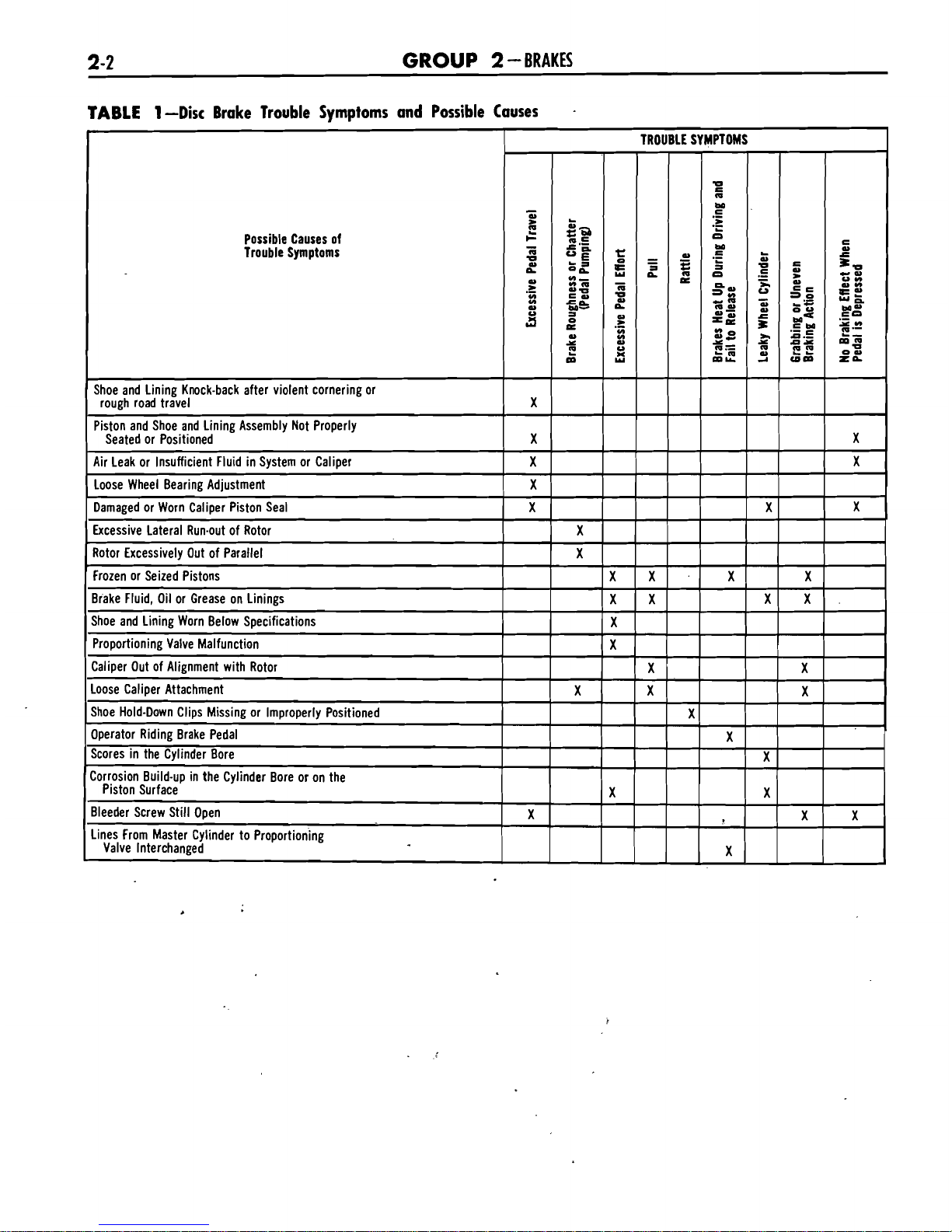
1-Disc Brake Trouble Symptoms and Possible Causes
Shoe and Lining Knock-back after violent cornering or
rough road travel
Piston and Shoe and Lining Assembly Not Properly
Seated or Positioned
Air Leak or Insufficient Fluid in System or Caliper
TROUBLE SYMPTOMS
=h=hg
-
e
-
2
.:
z
a
X
X
X
al
an
=
51
e;'
c.-
-
g
a
OY
cum
ZL
X
X
-
u
QJ
.-
-
u
e;
rn
2
.-
w
.-
-
n
.z
-
Ba
c"
.:
"na
r.~,
-&B
:
al
x
C
m
UE=-h
=
u
2
Ma
.-
w
n
n
al
Y
Y
Y
=
ea
w
e
r"
LU
-
,
~n
PART
2-
1
-
GENERAL BRARE SERVICE
2-3
TABLE
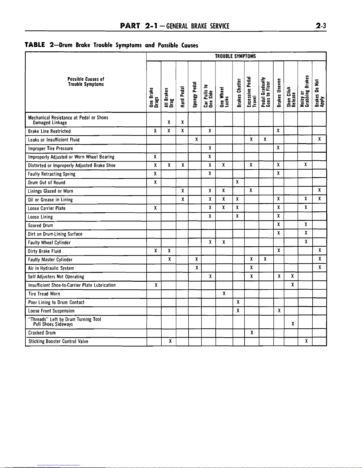
2-Drum Brake Trouble Symptoms and Possible Causes
Possible Causes of
Trouble Symptoms
Sticking Booster Control Valve
I
GROUP
2
-BRAKES
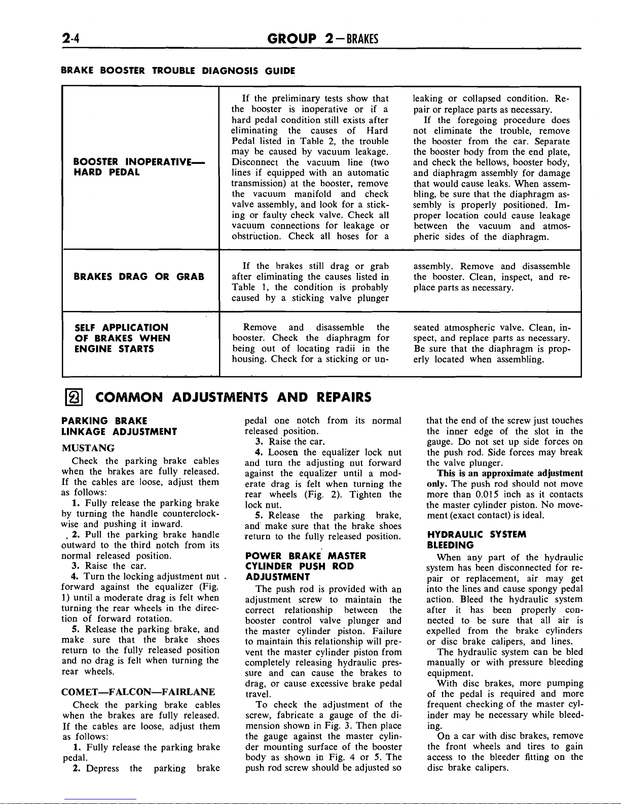
BRAKE BOOSTER TROUBLE DIAGNOSIS GUIDE
COMMON ADJUSTMENTS AND REPAIRS
BOOSTER INOPERATIVEHARD PEDAL
BRAKES DRAG OR GRAB
SELF APPLICATION
OF BRAKES WHEN
ENGINE STARTS
PARKING BRAKE
LINKAGE ADJUSTMENT
If the preliminary tests show that leaking or collapsed condition. Re-
the booster is inoperative or if a pair or replace parts as necessary.
hard pedal condition still exists after If the foregoing procedure does
eliminating the causes of Hard not eliminate the trouble, remove
Pedal listed in Table 2, the trouble the booster from the car. Separate
may be caused by vacuum leakage. the booster body from the end plate,
Disconnect the vacuum line (two and check the bellows, booster body,
lines if equipped with an automatic and diaphragm assembly for damage
transmission) at the booster, remove that would cause leaks. When
assemthe vacuum manifold and check bling, be sure that the diaphragm asvalve assembly, and look for a stick- sembly is properly positioned.
Iming or faulty check valve. Check all proper location could cause leakage
vacuum connections for leakage or between the vacuum and atmosobstruction. Check all hoses for a pheric sides of the diaphragm.
If the brakes still drag or grab assembly. Remove and disassemble
after eliminating the causes listed in
the booster. Clean, inspect, and
re-
Table
1,
the condition is probably place parts as necessary.
caused by a sticking valve plunger
Remove and disassemble the seated atmospheric valve. Clean, inbooster. Check the diaphragm for spect, and replace parts as necessary.
being out of locating radii in the Be sure that the diaphragm is
prop-
housing. Check for a sticking or un-
erly located when assembling.
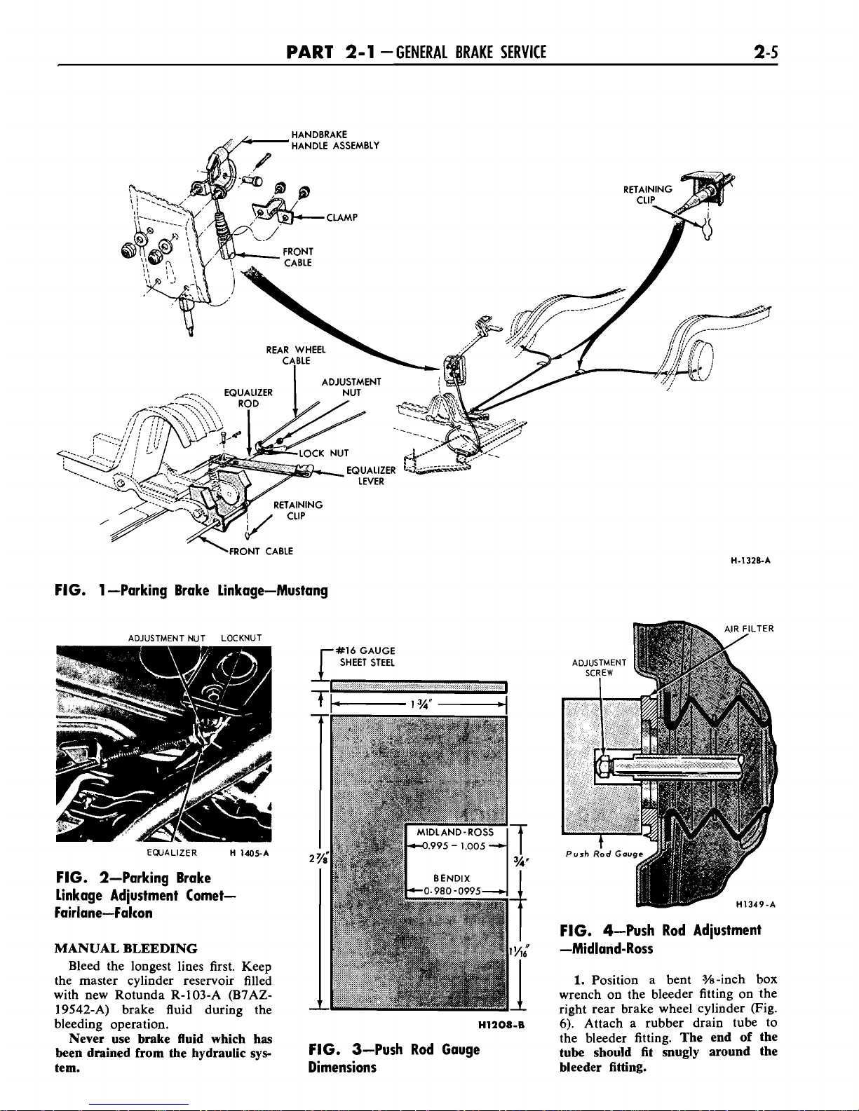
pedal one notch from its normal
released position.
MUSTANG
3.
Raise the car.
4.
Loosen the equalizer lock nut
Check the parking brake cables
and turn the adjusting nut forward
when the brakes are
fully released.
against the equ&zer-until a mod-
If the cables are loose, adjust them
erate drag is felt when turning the
as follows: rear wheels (Fig. 2). Tighten the
1.
Fully release the parking brake
lock nut.
by turning the handle counterclock-
5.
Release the parking brake,
wise and pushing it inward. and' make sure that the brake shoes
.
2.
Pull the parking brake handle
outward to the third notch from its
normal released position.
3.
Raise the car.
4.
Turn the locking adjustment nut
forward against the equalizer (Fig.
1)
until a moderate drag is felt when
turning the rear wheels in the direction of forward rotation.
5.
Release the parking brake, and
make sure that the brake shoes
return to the fully released position
and no drag is felt when turning the
rear wheels.
COMET-FALCONFAIRLANE
Check the parking brake cables
when the brakes are fully released.
If the cables are loose, adjust them
as follows:
1.
Fully release the parking brake
pedal.
2.
Depress the parking brake
'return to the fully released position.
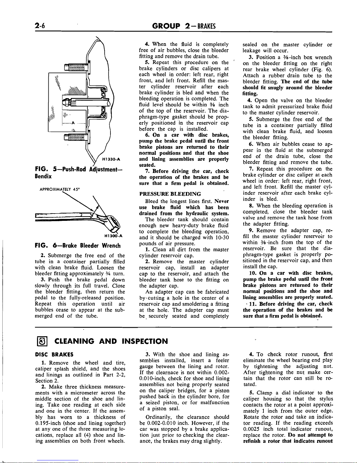
POWER BRAKE MASTER
CYLINDER PUSH ROD
ADJUSTMENT
The push rod is provided with an
adjustment screw to maintain the
correct relationship between the
booster control valve plunger and
the master cylinder piston. Failure
to maintain this relationship will prevent the master cylinder piston from
completely releasing hydraulic pressure and can cause the brakes to
drag, or cause excessive brake pedal
travel.
To check the adjustment of the
screw, fabricate a gauge of the dimension shown in Fig.
3.
Then place
the gauge against the master cylinder mounting surface of the booster
body as shown in Fig.
4
or
5.
The
push rod screw should be adjusted so
that the end of the screw just touches
the inner edge of the slot in the
gauge. Do not set up side forces on
the push rod. Side forces may break
the valve plunger.
This is an approximate adjustment
only.
The push rod should not move
more than
0.015
inch as it contacts
the master cylinder piston. No move-
ment (exact contact) is ideal.
HYDRAULIC SYSTEM
BLEEDING
When any part of the hydraulic
system has been disconnected for repair or replacement, air may get
into the lines and cause spongy pedal
action. Bleed the hydraulic system
after it has been properly con-
nected to be sure that all air is
expelled from the brake cylinders
or disc brake calipers, and lines.
The hydraulic system can be bled
manually or with pressure bleeding
equipment.
With disc brakes, more pumping
of the pedal is required and more
frequent checking of the master cylinder may be necessary while bleeding.
On a car with disc brakes, remove
the front wheels and tires to gain
access to the bleeder fitting on the
disc brake calipers.
PART
2-1
-GENERAL BRAKE SERVICE
2-5
\FRONT
CABLE
FIG. 1 -Parking Brake Linkage-Mustang
ADJUSTMENT NUT LOCKNUT
EQUALIZER
H
1405-A
FIG. 2-Parking Brake
Linkage Adjustment
Comet-
Fairlane-Falcon
MANUAL BLEEDING
Bleed the longest lines first. Keep
the master cylinder reservoir filled
with new Rotunda R-103-A
(B7AZ-
19542-A) brake fluid during the
bleeding operation.
Never use brake fluid which has
been drained from the hydraulic sys-
tem.
r
#16
GAUGE
SHEET STEEL
FIG. 4-Push Rod Adjustment
-Midland-Ross
1.
Position a bent %-inch box
wrench on the bleeder fitting on the
rieht rear brake wheel cylinder (Fig.
14,208-B
6;
Attach a rubber drain tube to
the bleeder fitting.
The end of the
FIG. 3-Push Rod Gauge
tube should fit snugly around the
-
Dimensions
bleeder fitting.
GROUP
2
-
BRAKES
/
FIG. 5-Push-Rod AdjustmentBendix
APPROXIMATELY
45"
\
FIG. 6-Brake Bleeder Wrench
2.
Submerge the free end of the
tube in a container partially filled
with clean brake fluid. Loosen the
bleeder fitting approximately
%I
turn.
3.
Push the brake pedal down
slowly through its full travel. Close
the bleeder fitting, then return the
pedal to the fully-released position.
Repeat this operation until air
bubbles cease to appear at the submerged end of the tube.
4.
When the fluid is completely
free of air bubbles, close the bleeder
fitting and remove the drain tube.
5.
Repeat this procedure on the
'
brake cylinders or disc calipers at
each wheel in order: left rear, right
front, and left front. Refill the master cylinder reservoir after each
brake cylinder is bled and when the
bleeding operation is completed. The
fluid level should be within
3/8
inch
of the top of the reservoir. The diaphragm-type gasket should be properly positioned in the reservoir cap
before the cap is installed.
6.
On a car with disc brakes,
pump the brake pedal until the front
brake pistons are returned to their
normal positions and that the shoe
and lining assemblies are properly
seated.
7.
Before driving the car, check
the operation of the brakes and be
sure that a firm pedal is obtained.
PRESSURE BLEEDING
Bleed the longest lines first.
Never
use brake fluid which has been
drained from the hydraulic system.
The bleeder tank should contain
enough new heavy-duty brake fluid
to complete the bleeding operation,
and it should be charged with 10-30
pounds of air pressure.
1.
Clean all dirt from the master
cylinder reservoir cap.
2.
Remove the master cylinder
reservoir cap, install an adapter
cap to the reservoir, and attach the
bleeder tank hose to the fitting on
the adapter cap.
An adapter cap can be fabricated
byecutting a hole in the center of a
reservoir cap and smoldering a fitting
at the hole. The adapter cap must
be, securely seated and completely
sealed on the master cylinder or
leakage will occur.
3.
Position a %-inch box wrench
on the bleeder fitting on the right
rear brake wheel cylinder (Fig.
6).
Attach a rubber drain tube to the
bleeder fitting.
The end of the
tube
should fit snugly around the bleeder
fitting.
4.
Open the valve on the bleeder
tank to admit pressurized brake fluid
to the master cylinder reservoir.
5.
Submerge the free end of the
tube in a container partially filled
with clean brake fluid, and loosen
the bleeder fitting.
6.
When air bubbles cease to appear in the fluid at the submerged
end of the drain tube, close the
bleeder fitting and remove the tube.
7.
Repeat this procedure on the
brake cylinder or disc caliper at each
wheel in order: left rear, right front,
and left front. Refill the master cylinder reservoir after each brake cylinder is bled.
8.
When the bleeding operation is
completed, close the bleeder tank
valve and remove the tank hose from
the adapter fitting.
9.
~kmove the adapter cap, refill the master cylinder reservoir to
within
%-inch from the top of the
reservoir. Be sure that the diaphragm-type gasket is properly po-
sitioned in the reservoir cap, and then
install the cap.
10.
On a car with disc brakes,
pump the brake pedal until the front
brake pistons are returned to their
normal positions and the shoe and
lining assemblies are properly seated.
+
11.
Before driving the car, check
the operation of the brakes and
be
sure that a firm pedal is obtained.
CLEANING AND INSPECTION
I
I
DISC
BRAKES
I
1.
Remove the wheel and tire,
caliper splash shield, and the shoes
and linings as outlined in Part 2-2,
Section
2.
2.
Make three thickness measurements with a micrometer across the
middle section of the shoe and
lin-
i
ing. Take one reading at each side
and one in the center. If the assembly has worn to a thickness of
0.195-inch (shoe and lining together)
at any one of the three measuring locations, replace all
(4)
shoe and lin-
ing assemblies on both front wheels.
3.
With the shoe and lining assemblies installed, insert a feeler
gauge between the lining and rotor.
If the clearnace is not within
0.002-
0.010-inch, check for shoe and lining
assemblies not being properly seated
on the caliper bridges, for a piston
pushed back in the cylinder bore, for
a seized piston, or for malfunction
of a piston seal.
Ordinarily, the clearance should
be 0.002-0.010 inch. However, if the
car was stopped by a brake application just prior to checking the clearance, the brakes may drag slightly.
4.
To check rotor runout, first
eliminate the wheel bearing end play
by tightening the adjusting nut.
After tightening the nut make cer-
tain that the rotor can still be rotated.
5.
Clamp a dial indicator to the
caliper housing so that the stylus
contacts the rotor at a point approxi-
mately
1
inch from the outer edge.
Rotate the rotor and take an indicator reading. If the reading exceeds
0.0025 inch total indicator
runout,
replace the rotor.
Do not attempt to
refinish a rotor that indicates
runout

PART
2-1
-
GENERAL BRAKE SERVICE
in excess of specification.
When the
runout check is finished be sure to
adjust the bearings
as
outlined in
Group
3,
in order to prevent bearing
failure.
6.
Check the rotor for scoring.
Minor scores can be removed with
a fine emery cloth. If the rotor is
excessively scored, replace it.
7.
Visually check the caliper. If it
is cracked it should be replaced. If
leakage or seized pistons is evident,
disassemble and repair the caliper as
required.
8.
If upon disassembly the caliper
is found to be distorted or damaged,
or if the cylinder bores are scored
or excessively worn, replace the as-
sembly.
The two halves of the caliper as-
sembly should never be separated.
Damage or failure of one requires
replacement of both as a unit.
DRUM BRAKES
1.
Remove the wheel from the
drum, and remove the drum as out-
lined in Part
2-2,
Section
2.
Wash
all the parts except the brake shoes
in a cleaning fluid and dry with com-
pressed air.
2.
Brush all dust from the carrier
plate and interior of the brake drum.
3.
Inspect the brake shoes for excessive lining wear or shoe damage.
If the lining is worn to within
'132
inch of the rivet heads or if the
shoes are damaged, they must be replaced. Replace any lining that has
been oil saturated. Replace the lining in axle sets. Prior to replacement
of the lining, the drum diameter
should be checked to determine if
oversize linings must be installed.
4.
Check the condition of the
brake shoes, retracting springs, and
drum for signs of overheating. If the
shoes have a slight blue coloring, or
if the springs show a change in free
length, indicating overheating, replacement of the retracting and hold
down springs is necessary.
Over-
heated springs lose their force and
could cause the new lining to wear
prematurely if they are not replaced.
5.
If the car has
30,000
or more
miles of operation on the brake linings, or signs of overheating are
present when relining brakes, the
wheel cylinders should be disassembled and inspected for wear and dirt
in the cylinder. The cylinder cups
and other parts contained in the
overhaul kit should be replaced,
thus avoiding future problems.
6.
Inspect all other brake parts
and replace any that are worn or
damaged.
7.
Inspect the brake drums and,
if necessary, refinish. Refer to Part
2-2,
Section 4 for refinishing.
BOOSTER UNITS
Disassembled views of the brake
booster are shown in Figs.
40, 49
and
SO,
Part
2-2.
After disassembly, immerse all
metal parts in a suitable solvent.
Use-only alcohol on rubber parts or
parts containing rubber. After the
parts have been thoroughly cleaned
and rinsed in cleaning solvent, the
metal parts which come in contact
with hydraulic brake fluid or rubber parts should be rewashed in
clean alcohol before assembly. Use
an air hose to blow dirt and cleaning
fluid from the recesses and internal
passages. When overhauling a power
booster, use all parts furnished in the
repair kit.
Discard all old rubber
parts.
Inspect all other parts for damage
or excessive wear. Replace damaged
or excessively worn parts. If the inside of the booster body is rusted
or corroded, polish it with steel wool
or fine emery cloth.
 Loading...