

Ford Comet 1964, 1964 Falcon Shop Manual


Copyright © 2007, Forel Publishing Company, LLC, Woodbridge, Virginia
All Rights Reserved. No part of this book may be used or reproduced in any manner
whatsoever without written permission of Forel Publishing Company, LLC. For
information write to Forel Publishing Company, LLC, 3999 Peregrine Ridge Ct.,
Woodbridge, VA 22192
1964 Ford Car Shop Manual
(with Technical Service Bulletin 1090-1, dated March 16, 1964)
Form 7760-64
ISBN: 1-60371-001-9
EAN: 978-1-60371-001-5
Forel Publishing Company, LLC
3999 Peregrine Ridge Ct.
Woodbridge, VA 22192
Email address: webmaster@ForelPublishing.com
Website: http://www.ForelPublishing.com
This publication contains material that is reproduced and distributed under a
license from Ford Motor Company. No further reproduction or distribution of the
Ford Motor Company material is allowed without the express written permission
of Ford Motor Company.
Disclaimer
Although every effort was made to ensure the accuracy of this book, no representations or warranties of
any kind are made concerning the accuracy, completeness or suitability of the information, either expressed
or implied. As a result, the information contained within this book should be used as general information
only. The author and Forel Publishing Company, LLC shall have neither liability n or responsibility to any
person or entity with respect to any loss or damage caused, or alleged to be caused, directly or indirectly by
the information contained in this book. Further, the publisher and author are not engaged in rendering legal
or other professional services. If legal, mechanical, electrical, or other expert assistance is required, the
services of a competent professional should be sought.

FOREWORD
This shop manual provides the Service Technician with com-
plete information for the proper servicing of the
1964
Comet
and Falcon cars.
The information is grouped according to the type of work
being performed, such as diagnosis and testing, frequently
performed adjustments and repairs, in-vehicle adjustments,
overhaul, etc. Specifications and recommended special tools
are included.
Refer to the opposite page for important vehicle identification data..
The descriptions and
specificarions in this manual were in
eflect at the time this manual was approved for printing. The
Ford Motor Company reserves the right to discontinue models
at any time, or change specifications or design, without notice
and without incurring obligation.
,
SERVICE DEPARTMENT
FORD MOTOR COMPANY
September
1997
COMET IDENTIFICATION
SILVER TURQUOISE TURQUOISE RANDOM FABRIC LIGHT ?-SPEED
POLAR WHITE TURQUOISE METALLIC CRUSH VINYL AUTOMATIC TRANSMISSION
COMET 404 4
/
/
DAY OF DETROIT
\
DOOR SEDAN
DM
17
26H
33
LORAIN ASSEMBLY PLANT
\
ENGINE'
170 CID 6-CYLINDER
BODY SERIAL IDENTIFICATION
N1218-B
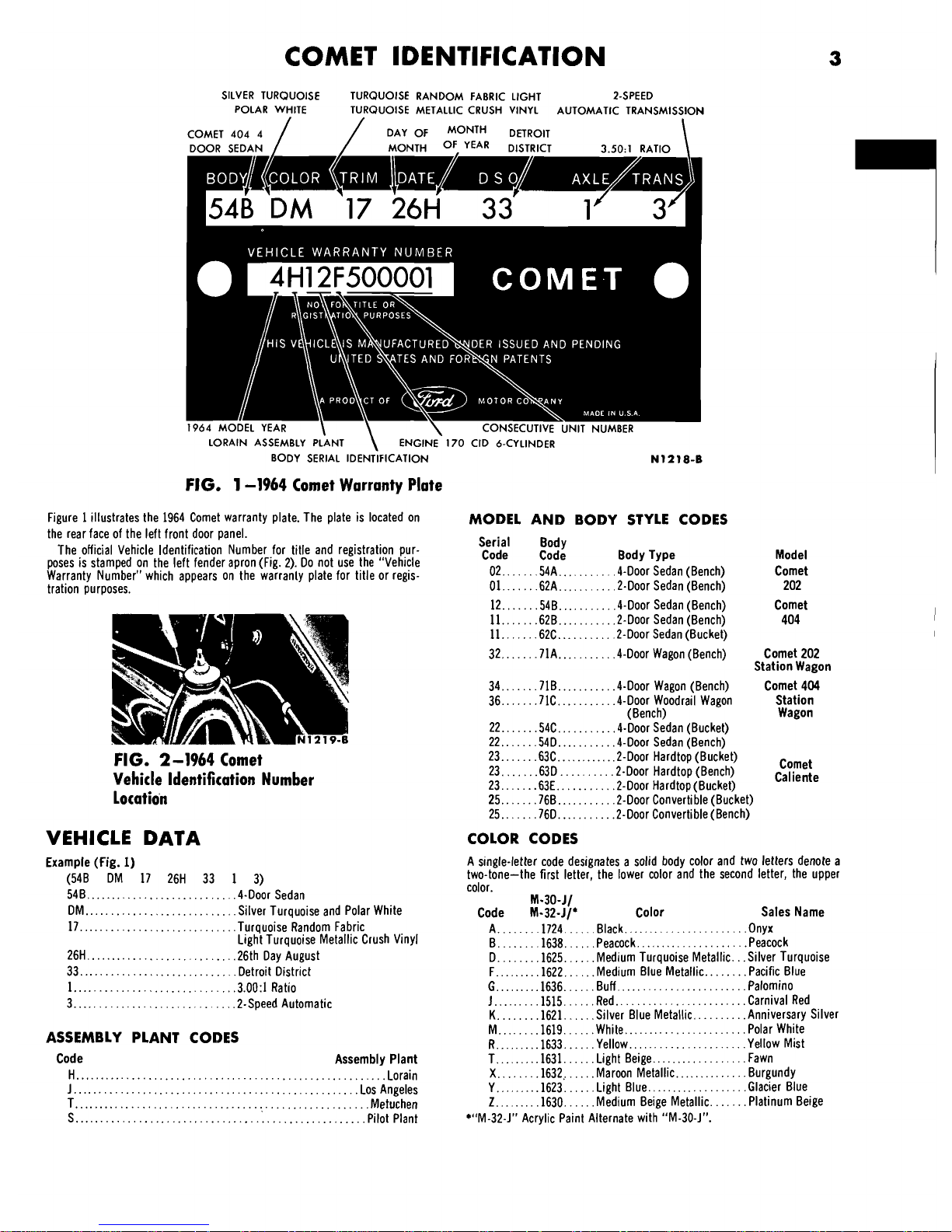
FIG. 1-1964 Comet Warranty Plate
Figure 1 illustrates the 1964 Comet warranty plate. The plate is located on
the rear face of the left front door panel.
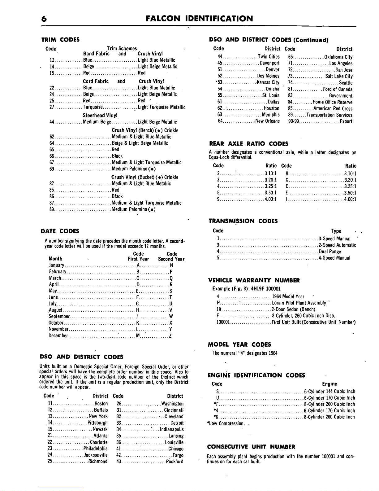
'The official Vehicle ldentification Number for title and registration pur-
poses is stamped on the left fender apron (Fig. 2). Do not use the
"Veh~cle
Warranty Number" which appears on the warranly plate for tltle or reglstration purposes.
FIG. 2-1964 Comet
Vehicle ldentification Number
Locatio'n
VEHICLE
DATA
Example (Fig.
1)
(548 DM 17 26H 33 1 3)
548..
.........................
.4-Door Sedan
DM..
.........................
.Silver Turquoise and Polar White
17..
..........................
.Turquoise Random Fabric
Light Turquoise Metallic Crush Vinyl
26H..
.........................
.26th Day August
33
............................
.Detroit District
1
.............................
.3.00:1 Ratio
3.
............................
.2-Speed Automatic
ASSEMBLY PLANT CODES
Code Assembly Plant
H..
.......................................................
Lorain
J
....................................................
Los Angeles
T..
.....................................................
Metuchen
S.
...................................................
.Pilot Plant
MODEL AND BODY STYLE CODES
Serial Body
Code Code Body Type Model
02..
....
.54A..
........
.&Door Sedan (Bench) Comet
01..
....
.62A..
........
.2-Door Sedan (Bench)
202
12..
....
.54B.
.........
.4-Door Sedan (Bench) Comet
11..
....
.62B..
........
.2-Door Sedan (Bench) 404
11..
....
.62C..
........
.2-Door Sedan (Bucket)
32..
....
.71A..
........
.4-Door Wagon (Bench) Comet 202
Station Wagon
....
........
34.. ,718.. .4-Door Wagon (Bench) Comet 404
36..
....
.71C..
........
.4-D00r Woodrail Wagon Station
(Bench) Wagon
22..
....
.54C..
........
.4-Door Sedan (Bucket)
22..
....
.54D..
........
.&Door Sedan (Bench)
23..
....
.63C..
.........
.2-Door Hardtop (Bucket)
Comet
23..
....
.63D..
.......
.2-Door Hardtop (Bench)
Caliente
23..
....
.63E..
........
.2-Door Hardtop (Bucket)
25..
....
,768..
........
.2-Door Convertible (Bucket)
25..
....
,760..
........
.2-Door Convertible(Bench)
COLOR CODES
A single-letter code designates a solid body color and two letters denote a
two-tone-the first letter, the lower color and the second letter, the upper
color.
M-30-J/
Code M-32-JI* Color Sales Name
.....
...
....................
A,. ,1724.. .Black.. .Onyx
.....
....
..................
8.. ,1638.
.Peacock.. .Peacock
D..
.....
,1625..
...
.Medium Turquoise Metallic.
.
.Silver Turquoise
F..
......
,1622..
...
.Medium Blue Metallic..
.....
.Pacific Blue
.....................
......
....
6..
,1636. .Buff.. .Palomino
......
...
.....................
1..
,1515.. .Red.. .Carnival Red
.....
...
.......
K..
,1621.. .Silver Blue Metallic.. .Anniversary Silver
.....
...
....................
M.. ,1619.. .White.. .Polar White
......
...
...................
R..
,1633.. .Yellow.. .Yellow Mist
...............
......
...
T.. .1631..
.Light Beige.. .Fawn
X..
.....
,1632,.
...
.Maroon Metallic..
...........
.Burgundy
................
......
....
Y.. ,1623. .Light Blue.. .Glacier Blue
......
... .....
2..
,1630.. .Medium Beige Metallic. .Platinum Beige
*"M-32-J" Acrylic Paint Alternate with "M-30-J".

TRIM CODES
A two-digit number indicates the type of trim and trim color.
If, due to unavailability or other difficulties in production, a particular trim
set is not intended for service (minor deviation from intended trim), the
warranty plate code will be followed with a numerical designation-For
example: 52-1, 52-2.
If the trim set is serviced directly, the warranty plate code will bear an
alphabetical suffix-For example: 52-A,
52-8.
Code Trim Schemes
Random Fabric and Crush Vinyl
12..
..........
.Blue..
...................
.Light Blue Metallic
....................
14..
..........
.Beige..
.Light Beige Metallic
16..
..........
.Black..
...........
:.
....
..Black
17..
..........
.Turquoise..
.........
:.
...
.Light Turquoise Metallic
Bright Check Fabric and Crush Vinyl
21..
..........
.Silver Blue.
..............
.Light Silver Blue Metallic
22..
..........
.Blue.
.................
:. .
.Light Blue Metallic
24..
..........
.Beige..
...................
.Light Beige Metallic
26..
..........
.Black..
...................
.Black
27..
..........
.Turquoise..
..............
.Light Turquoise Metallic
Crush Vinyl
(0)
Crinkle
32..
...................................
.Light Blue Metallic
35..
...................................
.Red
36..
...................................
.Black
37.
...................................
..Light Turquoise Metallic
39..
...................................
.Medium Palomino
(0)
Block Stripe Fabric and Crush Vinyl
:
42..
..........
.Blue..
..................
..Light Blue Metallic
44..
..........
.Beige..
.....
:
............
.Light Beige Metallic
46..
..........
.Black..
..................
.Black
DSO AND DISTRICT CODES
Units built on a Domestic Special Order, Foreign Special Order, or other
special orders will have the complete order number in this space. Also to
appear in this space is the two-digit code'number of the District which
ordered the unit. If the unit isa regular production unit, only the District
code number will appear.
Code District Code
,
District
:
...................
11..
......:....
:
....
.Boston 34.. .Detroit
...................
12..
...........
.Philadelphia 41.. .Chicago
13..
..............
.New York 44..
..................
.St. Louis
................
14..
..
.:
.........
.Washington 45.. .Twin Cities
...................
21..
................
.Atlanta 51.. .Denver
................
.................
22.. .Dallas 52.. Los Angeles
..................
.
24..
............
.Jacksonville 53.. .Oakland
...................
25:.
...............
Mem~his 54.. .Seattle
.
.
31.
.................
.Buffalo 81..
............
.Ford of Canada
32..
.............
;.Cincinnati . 84..
.......
.Home Office Reserve
33..
..............
.Cleveland 90-99..
.................
.Export
REAR AXLE RATIO CODES
A number designates a-conventional axle, while a letter designates an EquaLock differential.
Code Ratio
1..
......................................................
.3.00:1
3..
......................................................
.3.20:1
4..
......................................................
.3.25:1
5..
......................................................
.3.50:1
6
........................
.:..
............................
.2.80:1
TRANSMISSION CODES
Crush Vinyl
(0)
Crinkle
Code
..................
.Light Blue Metallic
1
..................
.Red
3
..................
Black
4
..................
.Light Turquoise Metallic
5
-
69..
...................................
.Medium Palomino
(0)
.
Crush Vinyl
(0)
Crinkle
72.
..............................
..Medium and Light Blue Metallic
75..
..............................
.Red
76..
.......................
.I..
...
.Black
..
..............
...........
79..
;
.:
.Medium Palomino
(0)
Crinkle Vinyl
89.
...............................
.Medium Palomino
..
DATE CODES
A number signifying thedate precedes the month code letter. A second-year
code letter will be used
~f
the model exceeds 12 months.
Code Code
First Year Second Year
Month
............
.............................
January.. .A,. N
............
February..
............................
.B.. P
March..
...............................
.C..
............
Q
...........
.........................
April..
.......
:
D.. .R
............
May..
..................................
E.. S
..........
June
.................................
..F.. ..T
...........
July
...................................
.G..
.U
...........
August..
...............................
H..
.V
.............
September..
............................
J.. W
............
October.
...........
..
.................
K..
X
November..
............................
L..
............
Y
December..
.............................
M..
............
Z
Type
.3-Speed Manual
...........
...........
.2-Speed Automatic
...........
.Dual Range 3-Speed Automatic
............
.4-Speed Manual
VEHICLE WARRANTY NUMBER
'
Example (Fig.
lj:
4H
12F 500001
4..
..............................
.I964 Model Year
H..
..............................
.Lorain Pilot Plant Assembly
12..
.............................
.4-Door Sedan
.
F..
..............................
.8;Cylinder, 260 Cubic Inch Disp.
500001..
..........................
First Unit Built
(Consecutive Unit
NO.)
MODEL YEAR CODE
The numeral "4" designates 1964.
ENGINE IDENTIFICATION CODES
Code Engine
U...
...................................
.6-Cylinder 170 Cubic Inch
T..
....................................
.6-Cylinder 200 Cubic Inch
F..
....................................
.8-Cylinder 260 Cubic Inch
K..
....................................
.8-Cylinder 289 Cubic Inch
*4
......
:..
..............................
.6-Cylinder 170 Cubic Inch
*6..
.....................................
.8-Cylinder 260 Cubic Inch
.
*Low Compression!
CONSECUTIVE UNIT. NUMBER
Each model yea!, each assembly ,plant begins production with the number
500001 and
continues
on for each car butlt.

FALCON IDENTIFICATION
DYNASTY
GREEN TURQUOISE CORD FABRIC LIGHT AUTOMATIC
WlMBLEDON WHITE
TURQUOISE
METALLIC CRUSH VINYL
TRANSMISSION
FUTURA DAY OF MONTH
DETROIT 3.50:1
-
- -
1964 MODEL
YEAR
\
\
CONSECUTIVE
UNIT
NUMBER
LORAIN ASSEMBLY PLANT
\
ENGINE 170 CID 6-CYLINDER
BODY SERIAL IDENTIFICATION
N1238-6
FIG.
3-1964
Falcon Warranty Plate
Figure 1 illustrates the 1964 Falcon Warranty Plate. The plate is located on
the rear face of the left front door panel.
MODEL AND BODY STYLE CODES
The official Vehicle Identification Number for title and registration purposes
Serial Body Body
is stamped on the left cowl-to-front-spring pocket strut (Fig. 4). Do not use
Code Code
Type Model
the "Vehicle Warranty Number" which appears on the Warranty plate for
02..
...
.54A..
....
.&Door Sedan
title or registration purposes.
02..
...
.54D..
....
.4-Door Sedan (RPO) Standard
01..
...
.62A..
....
.2-Door Sedan
Sedan
Vehicle ldentification Number
Location
VEHICLE
DATA
Example
(Fig. 3):
(628 DM 27 26H 33 5 3)
628..
.........................
Futura 2-Door Sedan
DM..
........................
.Dynasty Green and Wimbledon White
27..
.........................
.Turquoise Cord Fabric
Light Turquoise Met. Crush Vinyl
26H..
........................
.26th Day August
33..
.........................
.Detroit District
5..
..........................
.3.50:1 Ratio
3..
..........................
.2-Speed Automatic
ASSEMBLY PLANT CODES
Code Assembly Plant
A..
...................................................
.Atlanta
H.
....................................................
Lorain
K
.................................................
.Kansas City
R..
.................................................
.San Jose
S..
................................................
.Pilot Plant
T..
..................................................
Metuchen
01..
...
.62D..
....
.2-Door Sedan (RPO)
16..
...
.54B..
....
.+Door Sedan ((Bench)
19..
...
.62B..
....
.2-Door Sedan (Bench)
17..
...
.63B..
....
.2-Door Hardtop (Bench)
11..
...
.63C..
....
.2-Door Hardtop (RPO Bucket) Futura
13..
...
.63D..
....
.2-Door Hardtop Sprint (RPO Bucket)
15..
...
.76A..
....
.Convertible (Bench)
12..
...
.76B..
....
.Convertible (RPO Bucket)
14..
...
.76D..
....
.Convertible Sprint (RPO Bucket)
21..
...
.59A..
...
.2-Door Wagon
22..
...
.71A..
....
.4-Door Wagon
Station
24..
...
,718..
....
.4-Door Wagon Deluxe Wagons
26..
...
.71C..
....
.4-Door Squire
27..
...
.66A..
....
.2-Door Standard Ranchero
Ranchero
27..
...
,668..
....
.2-Door Deluxe Ranchero
29..
...
.78A..
....
.Standard Sedan Delivery
Sedan
29..
...
.78B..
....
.Deluxe Sedan Delivery
Delivery
COLOR CODES
A single letter code designates a solid body color and two letters denote a
two-tone-the first letter, the lower color and the second letter, the upper
color.
M-30-J/
Code
M-32-J#
Color Sales Name
A,.
.....
,1724..
...
.Black..
....................
.Raven Black
..
D..
.....
,1625.
....
.Medium Turquoise Metallic.. Dynasty Green
.....
F..
......
,1622..
...
.Medium Blue Metallic..
.Guardsman Blue
......
...
......................
G.. ,1636.. .Buff.. .Prairie Tan
1..
......
,1515..
...
.Red..
.......................
.Rangoon Red
........
K..
.....
,1621..
...
.Silver Mink Metallic.
.Silvermore Gray
M..
.....
,1619.
....
.White..
.....................
Wimbledon White
X..
.....
.1632.
.....
.Maroon Metallic..
...........
.Vintage Burgundy
Y..
......
,1623..
...
.Light Blue..
................
.Skylight Blue
.....
2..
......
,1630..
...
.Medium Beige Metallic..
.Chantilly Beige
#"M-32-J" Acrylic Paint Alternate with "M-30-J".
6
FALCON IDENTIFICATION
TRIM CODES
Code Trim Schemes
Band Fabric and Crush Vinyl
12..
.........
..Blue..
..................
.Light Blue Metallic
.
14..
..........
.Beige..
.................
.Light Beige Metallic
15..
..........
.Red..
...................
.Red
Cord Fabric and Crush Vinyl
.
22..
..........
.Blue..
..................
.Light Blue Metallic
.
24..
..........
.Beige..
................
..Light Beige Metallic
.
..........
...................
25.. .Red.. .Red
27..
..........
.Turquoise..
.............
.Light ~urquoise Metallic
Steerhead Vinyl
44..
..........
.Medium Beige..
.........
.Light Beige Metallic
Crush Vinyl
(Bench)'(a) Crinkle
62..
.......................
.Medium & Light Blue Metallic
64..
........................
Beige & Light Beige Metallic
65..
.......................
.Red
66..
.......................
.Black
67..
.......................
.Medium & Light Turquoise Metallic
69..
.......................
.Medium Palomino (a)
Crush Vinyl (Bucket) (a) Crinkle
82..
.......................
.Medium & Light Blue Metallic
85..
.......................
.Red
86..
........................
Black
87..
.......................
.Medium & Light Turquoise Metallic
89..
.......................
.Medium Palomino (a)
DATE CODES
A
number signifying the date precedes the month code letter. A second
year code letter will be used if the model exceeds 12 months.
Code Code
Month First Year Second Year
January..
..............................
.A,.
............
N
February..
.............................
.B..
...........
.P
March..
...............................
.C..
...........
.Q
April..
...............
..
..............
D..
....
;,
......
R
May..
..................................
E..
............
S
June
...................................
.F...
..........
.T
July..
.................................
.G
.............
.U
.......................
........
...........
August..
:
H..
.V
September..
.........................
.J,
.............
W
October..
.............
..
...
..
.........
K..
............
X
November.
..............................
L..
............
Y
December..
..............................
M..
...........
.Z
DSO AND DISTRICT CODES
Units built on a Domestic Special Order, Foreign Special Order, or other
special orders will have-the complete order number in this space. Also to
appear in this space is the two-digit code number of the District which
ordered the unit. If the unit is a regular production unit, only the District
code number will appear.
Code
'
,
District Code District
11..
...............
..Boston
12.
....
:.
...........
.Buffalo
13.
...............
.New York
.............
-14.. .Pittsburgh
15..
................
.Newark
21..
................
.Atlanta
22..
...............
.Charlotte
23..
...........
.Philadelphia
24..
............
.Jacksonville
25..
..............
.Richmond
26..
...............
.Washington
31..
..................
.Cincinnati
32..
...............
:.
.Cleveland
33..
....................
Detroit
34..
.................
Indianapolis
35..
...................
.Lansing
36..
..................
Louisville
41..
.......
:.
..........
.Chicago
42.
......................
Fargo
43..
...................
~ockford
DSO AND DISTRICT CODES (Continued)
Code District Code District
44..
.............
.Twin Cities
65..
:.
..........
.Oklahoma City
45..
..............
.Davenport
71..
...............
Los Angeles
51..
.................
.Denver
72..
.
;.
..............
.San Jose
52..
..............
Des Moines
73..
............
.Salt Lake City
'53..
...............
Kansas City
74..
..................
.Seattle
54..
.................
.Omaha
81..
...........
.Ford of Canada
55..
................
.St. Louis
83..
..............
.Government
61..
..................
.Dallas
84..
......
.Home Office Reserve
62.:.
...............
.Houston
85..
.......
.American Red Cross
63.
................
.Memphis
89..
....
.Transportation Services
64
..............
:New Orleans
90-99.
.................
.Export
REAR AXLE RATIO CODES
A number designates a conventional axle, while a letter designates an
Equa-Lock differential.
Code Ratio Code Ratio
2..
.....
:.
...........
.3.10:1
0..
.......................
.3.10:1
3..
..................
.3.20:1
C..
.......................
.3.20:1
4
....................
.3.25:1
D.
........................
.3.25:1
5..
..................
.3.50:1
E..
.......................
.3.50:1
9..
..................
.4.00:1
1..
.......................
.4.00:1
TRANSMISSION CODES
Code Type
-
.
1..
...........................................
.3-Speed Manual
.
...........................................
3.. .2-Speed Automatic
4..
...........................................
.Dual Range
5..
...........................................
.4-Speed Manual
VEHICLE WARRANTY NUMBER
Example (Fig.
3):
4H19F 100001
4..
......................
.I964 Model Year
H.
.........
:.
.............
Lorain Pilot Plant Assembly
.
19.
.....................
.2-Door Sedan (Bench)
F..
......................
.8-Cylinder, 260 Cubic Inch Disp.
100001
.....................
First Unit Built (Consecutive Unit Number)
MODEL YEAR CODES
The numeral "4" designates 1964
ENGINE
IDENTIFICATION
CODES
Code Engine
.
S..
....................................
.6-Cylinder 144 Cubic Inch
U..
....................................
.6-Cylinder 170 Cubic Inch
*F..
....................................
.8-Cylinder 260 Cubic Inch
*4..
....................................
.6-Cylinder 170 Cubic Inch
....................................
*6.. .8-Cylinder 260 Cubic Inch
*Low Compression.
.
CONSECUTIVE UNIT NUMBER
Each assembly plant begins production with the number 100001 and continues on for each car built.
2
-1
PART 2-1 PAGE PART 2-3 PAGE
GENERAL BRAKE SERVICE
..........
.2-1
SPECIFICATIONS
..............
.2-20
PART 2-2
BRAKE SYSTEM
.................
.2-6
PART
2-1
GENERAL BRAKE SERVICE
Section Page Section Page
..................
1 Diagnosis and Testing
.....................
.2-1
3 Cleaning and Inspection
.2-4
2 Common Adjustments and Repairs
.........
.2-3
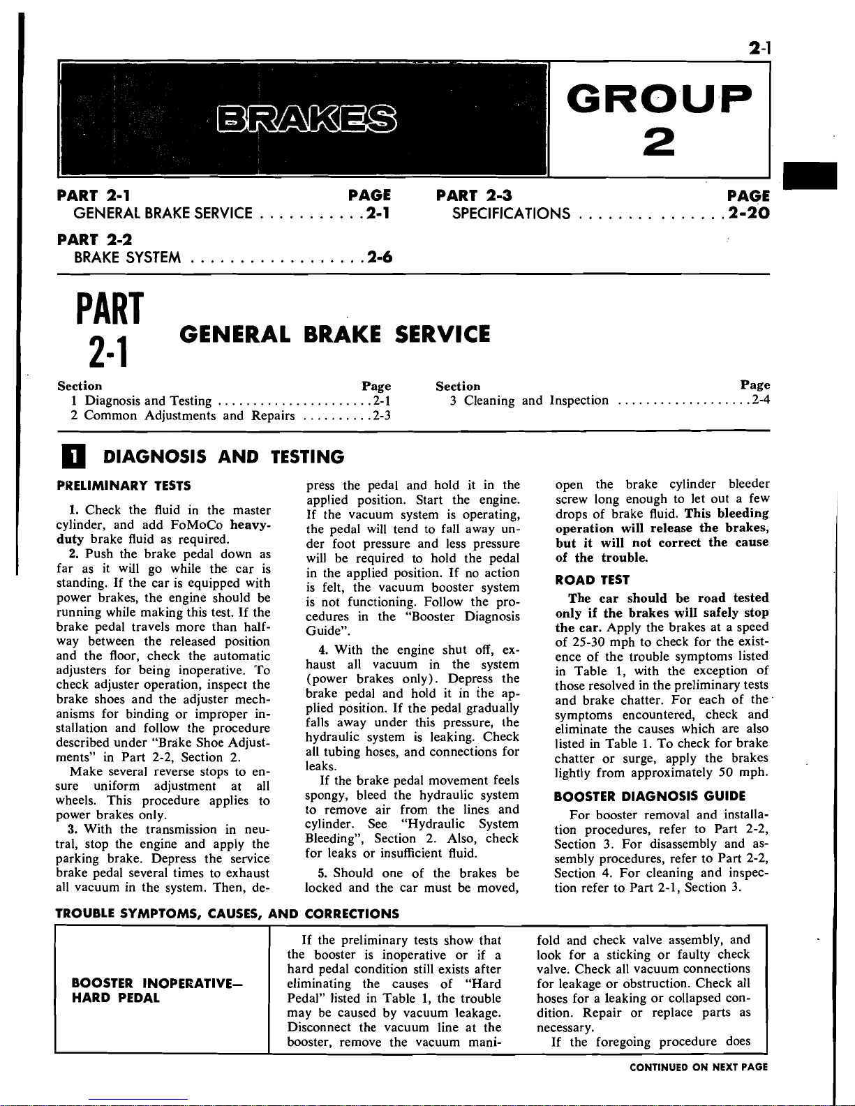
DIAGNOSIS AND TESTING
PRELIMINARY TESTS
1.
Check the fluid in the master
cylinder, and add
FoMoCo
heavy-
duty
brake fluid as required.
2.
Push the brake pedal down as
far as it will go while the car is
standing. If the car is equipped with
power brakes, the engine should be
running while making this test. If the
brake pedal travels more than halfway between the released position
and the floor, check the automatic
adjusters for being inoperative. To
check adjuster operation, inspect the
brake shoes and the adjuster mechanisms for binding or improper installation and follow the procedure
described under "Brake Shoe Adjustments" in Part 2-2, Section 2.
Make several reverse stops to ensure uniform adjustment at all
wheels. This procedure applies to
power brakes only.
3.
With the transmission in neutral, stop the engine and apply the
parking brake. Depress the service
brake pedal several times to exhaust
all vacuum in the system. Then, de-
press the pedal and hold it in the
applied
position. Start the engine.
If the vacuum system is operating,
the pedal will tend to fall away under foot pressure and less pressure
will be required to hold the pedal
in the applied position. If no action
is felt, the vacuum booster system
is not functioning. Follow the procedures in the "Booster Diagnosis
Guide".
4.
With the engine shut off, ex-
haust all vacuum in the system
(power brakes only). Depress the
brake pedal and hold it in the applied position. If the pedal gradually
falls away under this pressure, the
hydraulic system is leaking. Check
all tubing hoses, and connections for
leaks.
If the brake pedal movement feels
spongy, bleed the hydraulic system
to remove air from the lines and
cylinder. See "Hydraulic System
Bleeding", Section 2. Also, check
for leaks or insufficient fluid.
5.
Should one of the brakes be
locked and the car must be moved,
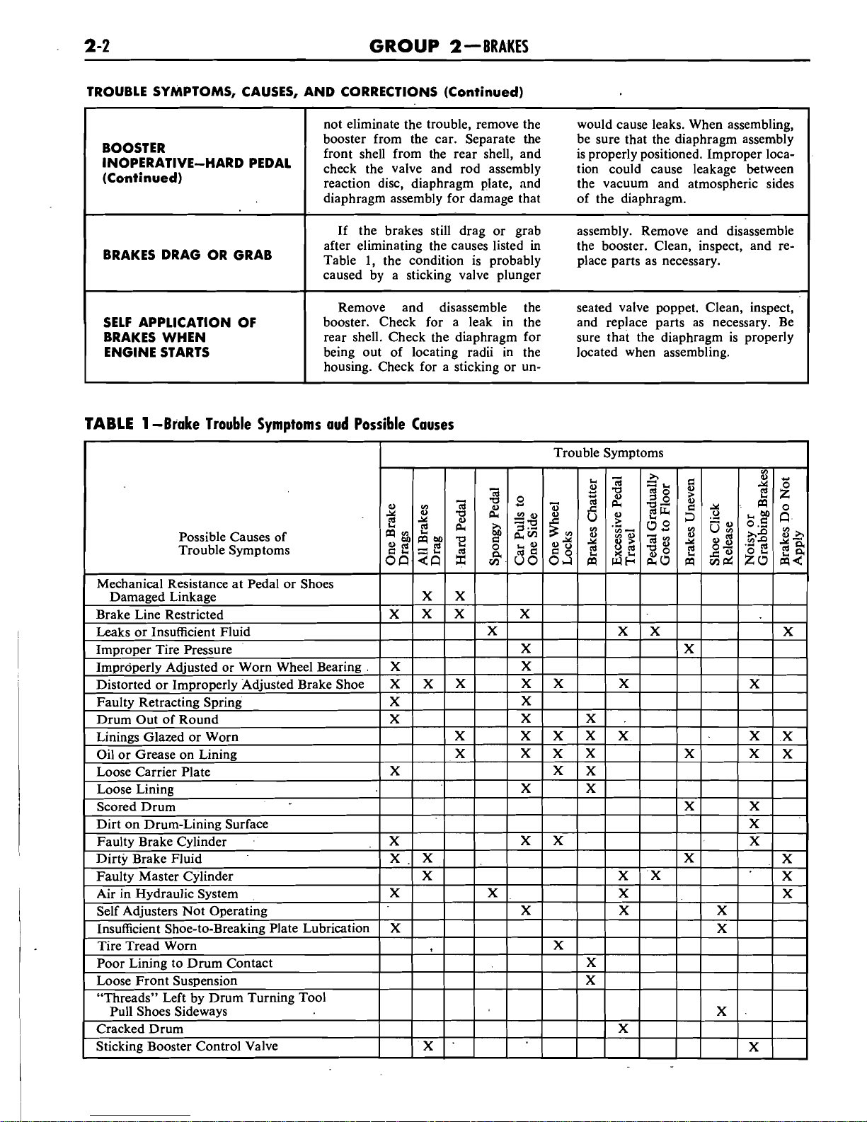
TROUBLE SYMPTOMS, CAUSES, AND CORRECTIONS
open the brake cylinder bleeder
screw long enough to let out a few
drops of brake fluid.
This bleeding
operation will release the brakes,
but it will not correct the cause
of the trouble.
ROAD TEST
The car should be road tested
only if the brakes
wilI safely stop
the car.
Apply the brakes at a speed
of 25-30 mph to check for the existence of the trouble symptoms listed
in Table 1, with the exception of
those resolved in the preliminary tests
and brake chatter. For each of the
symptoms encountered, check and
eliminate the causes which are also
listed
in
Table 1. To check for brake
chatter or surge, apply the brakes
lightly from approximately 50 mph.
BOOSTER DIAGNOSIS GUIDE
For booster removal and installation procedures, refer to Part 2-2,
Section 3. For disassembly and assembly procedures, refer to Part 2-2,
Section
4.
For cleaning and inspec-
tion refer to Part 2-1, Section 3.
BOOSTER INOPERATIVEHARD PEDAL
If the preliminary tests show that
the booster is inoperative or if a
hard pedal condition still exists after
eliminating the causes of "Hard
Pedal" listed in Table 1, the trouble
may be caused by vacuum leakage.
Disconnect the vacuum line at the
booster, remove the vacuum mani-
fold and check valve assembly, and
look for a sticking or faulty check
valve. Check all vacuum connections
for leakage or obstruction. Check all
hoses for a leaking or collapsed condition. Repair or replace parts as
necessary.
If the foregoing procedure does
CONTINUED ON NEXT PAGE
2-2
GROUP
SOBRAKES
TROUBLE SYMPTOMS, CAUSES, AND CORRECTIONS (Continued)
TABLE
1
-Brake Trouble Symptoms aud Possible Causes
BOOSTER
PEDAL
(Continued)
BRAKES DRAG OR GRAB
SELF
APPLICATION OF
BRAKES WHEN
ENGINE STARTS
Trouble Symptoms
-
a
Possible Causes of
Trouble Symptoms
not eliminate the trouble, remove the
would cause leaks. When assembling,
booster from the car. Separate the
be sure that the diaphragm assembly
front shell from the rear shell, and
is properly positioned. Improper locacheck the valve and rod assembly tion could cause leakage between
reaction disc, diaphragm plate,
and the vacuum and atmospheric sides
diaphragm assembly for damage that
of the diaphragm.
If the brakes still drag or grab assembly. Remove and disassemble
after eliminating the causes listed
in
the booster. Clean, inspect, and reTable
1,
the condition is probably place parts as necessary.
caused by a sticking valve plunger
Remove and disassemble the seated valve poppet. Clean, inspect,
booster. Check for a leak in the and replace parts as necessary. Be
rear shell. Check the diaphragm for sure that the diaphragm is properly
being out of locating radii in the located when assembling.
housing. Check for a sticking or
un-

PART
2
-1 - GENERALJBRAKE SERVICE
2
-3
COMMON ADJUSTMENTS AND REPADRS
'FRONT
CABLE
FIG.
1
-Parking Brake Linkage
PARKING BRAKE
and no drag is felt when turning
LINKAGE ADJUSTMENT
the rear wheels.
Check the parking brake cables
MASTER CYLINDER PUSH
when the brakes are fully released.
ROD ADJUSTMENT-
If the cables are loose, adjust them
POWER BRAKES
as follows.
1.
Fully release the parking brake
by turning the handle counterclockwise and pushing it inward.
2.
Pull the parking brake handle
outward one notch from its normal
released position.
3.
Raise the car.
"'4.EF"ifi'
tbi: 16ck''nut 'in ?frolit df
tti&)kqu+lii~~ ('~ig..
1
y:
kGeia1 .turns
f$<+jja<dd:..
'."';?,.
'
'%.?~uni'.the adjustment nut forward against the equalizer until a
moderate drag is felt when turning
the rear wheels.
6.
When the cables are properly
adjusted, tighten the lock nut in the
direction of forward rotation against
the equalizer.
7.
Release the parking brake, and
make sure that the brake shoes re-
turn to the fully released position
The push rod is provided with an
adjustment screw to maintain the
correct relationship between the
booster control valve plunger and the
master cylinder piston. Failure to
maintain this relationship will prevent
the master cylinder piston from
completely releasing ,hydraulic pressure and can cause the brakes to
drag, or cause excessive brake pedal
travel.
To check the adjustment of the
screw, fabricate a gauge of the di-
mensions shown in Fig.
2.
Then
place the gauge against the. master
cylinder mounting surface of the
booster body as shown in Fig.
3.
The
push rod screw should be adjusted
so that the end of the screw just
touches the inner edge of the slot
in the gauge. Do not set up side
forces on the push rod. Side forces
may break the valve plunger.
This
is
an approximate adjust-
ment only.
The master cylinder pis-
ton should not move more than
0.015
inch as it contacts the push rod. No
movement (exact contact) is ideal.
,
HYDRAULIC SYSTEM BLEEDING.
When any part of the hydraulic
FIG.
2-Push
Rod
Gauge Dimensions
GROUP
2-BRAKES
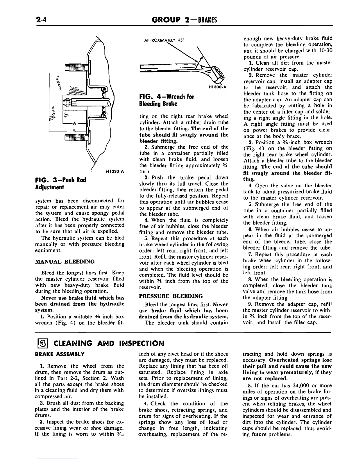
FIG. 3-Push Rod
Adiustment
system has been disconnected for
repair or replacement air may enter
the system and cause spongy pedal
action. Bleed the hydraulic system
after it has been properly connected
to be sure that all air is expelled.
The hydraulic system can be bled
manually or with pressure bleeding
equipment.
MANUAL BLEEDING
Bleed the longest lines first. Keep
the master cylinder reservoir filled
with new heavy-duty brake fluid
during the bleeding operation.
Never use brake fluid which has
been drained from the hydraulic
system.
1.
Position a suitable %-inch box
wrench (Fig.
4)
on the bleeder fit-
APPROXIMATELY
45'
\
FIG. 4-Wrench for
Bleeding Brake
ting on the right rear brake wheel
cylinder. Attach a rubber drain tube
to the bleeder fitting.
The end of the
tube should fit snugly around the
bleeder fitting.
2.
Submerge the free end of the
tube in a container partially filled
with clean brake fluid, and loosen
the bleeder fitting approximately
J/4
turn.
3.
Push the brake pedal down
slowly thru its full travel. Close the
bleeder fitting, then return the pedal
to the fully-released position. Repeat
this operation until air bubbles cease
to appear at the submerged end of
the bleeder tube.
4.
When the fluid is completely
free of air bubbles, close the bleeder
fitting and remove the bleeder tube.
5.
Repeat this procedure at each
brake wheel cylinder in the following
order: left rear, right front, and left
front. Refill the master cylinder reser-
voir after each wheel cylinder is bled
and when the bleeding operation is
completed. The fluid level should be
within
%
inch from the top of the
reservoir.
PRESSURE BLEEDING
Bleed the longest lines first.
Never
use brake fluid which has been
drained from the hydraulic system.
The bleeder tank should contain
CLEANING AND INSPECTION
BRAKE ASSEMBLY
1.
Remove the wheel from the
drum, then remove the drum as outlined in Part
2-2,
Section
2.
Wash
all the parts except the brake shoes
in a cleaning fluid and dry them with
compressed air.
2.
Brush all dust from the backing
plates and the interior of the brake
drums.
3.
Inspect the brake shoes for excessive lining wear or shoe damage.
If the lining is worn to within
%z
inch of any rivet head or if the shoes
are damaged, they must be replaced.
Replace any lining that has been oil
saturated. Replace lining in axle
sets. Prior to replacement of lining,
the drum diameter should be checked
to determine if oversize linings must
be installed.
4.
Check the condition of the
brake shoes, retracting springs, and
drum for signs of overheating. If the
springs show any loss of load or
change in free length, indicating
overheating, replacement of the re-
enough new heavy-duty brake fluid
to complete the bleeding operation,
and it should be charged with
10-30
pounds of air pressure.
1.
Clean all dirt from the master
cylinder reservoir cap.
2.
Remove the master cylinder
reservoir cap, install
an
adapter cap
to the reservoir, and attach the
bleeder tank hose to the fitting on
the adapter cap. An adapter cap can
be fabricated by cutting a hole in
the center of a filler cap and soldering a right angle fitting in the hole.
A right angle fitting must be used
on power brakes to provide clearance at the body brace.
3.
Position a %-inch box wrench
(Fig.
4)
on the bleeder fitting on
the right rear brake wheel cylinder.
Attach a bleeder tube to the bleeder
fitting.
The end of the tube should
fit snugly around the bleeder fitting.
4.
Open the valve on the bleeder
tank to admit pressurized brake fluid
to the master cylinder reservoir.
5.
Submerge the free end of the
tube in a container partially filled
with clean brake fluid, and loosen
the bleeder fitting.
6.
When air bubbles cease to appear in the fluid at the submerged
end of the bleeder tube, close the
bleeder fitting and remove the tube.
7.
Repeat this procedure at each
brake wheel cylinder in the follow-
ing order: left rear, right front, and
left front.
8.
When the bleeding operation is
completed, close the bleeder tank
valve and remove the tank hose from
the adapter fitting.
9.
Remove the adapter cap, refill
the master cylinder reservoir to within
%
inch from the top of the reser-
voir, and install the filler cap.
tracting and hold down springs is
necessary.
Overheated springs lose
their pull and could cause the new
lining to wear prematurely, if they
are not replaced.
5.
If the car has
24,000
or more
miles of operation on the brake linings or signs of overheating are present when relining brakes, the wheel
cylinders should be disassembled and
inspected for wear and entrance of
dirt into the cylinder. The cylinder
cups should be replaced, thus avoid-
ing future problems.

PART
2-1
-GENERAL BRAKE SERVICE
2
-5
6.
Inspect all other brake parts
and replace any that are worn or
damaged.
7.
Inspect the brake drums and, if
necessary, refinish them. Refer to
Part
2-2,
Section 4 for refinishing.
BOOSTER UNIT
A disassembled view of the brake
booster is shown in Fig.
5.
MOUNTING
VALVE
AND ROD
After disassembly, immerse all
metal parts
in
a suitable solvent. Use
only alcohol on rubber parts or parts
containing rubber. After the parts
have been thoroughly cleaned and
rinsed
in
cleaning solvent, the metal
parts which come in contact with
hydraulic brake fluid or rubber parts
should be rewashed in clean alcohol
before assembly. Use
an
air hose to
blow dirt and cleaning fluid from the
recesses and internal passages. When
overhauling a power booster, use all
parts furnished in the repair kit.
Discard all old rubber parts.
Inspect all other parts for damage
or excessive wear. Replace damaged
or excessively worn parts. If the in-
side of the booster shells are rusted
or corroded, polish them with steel
wool or fine emery cloth.
SEAL
I
VACUUM
SEAL REAR SHELL
CHECK VALVE
SEAL
PRIMARY
\
CUP
$TON
FIG.
5-Brake Booster and Master Cylinder Disassembled
PART
Section
Page
...............
BRAKE SYSTEM
1
Description and Operation 2-6
2
In-Car Adjustments and Repairs
...........
2-9
.................
2-2
3 Removal and Installation 2-13
4
Major Repair Operations
............'.....
2-16
DESCRIPTION AND OPERATION
REAR BRAKE FRONT BRAKE
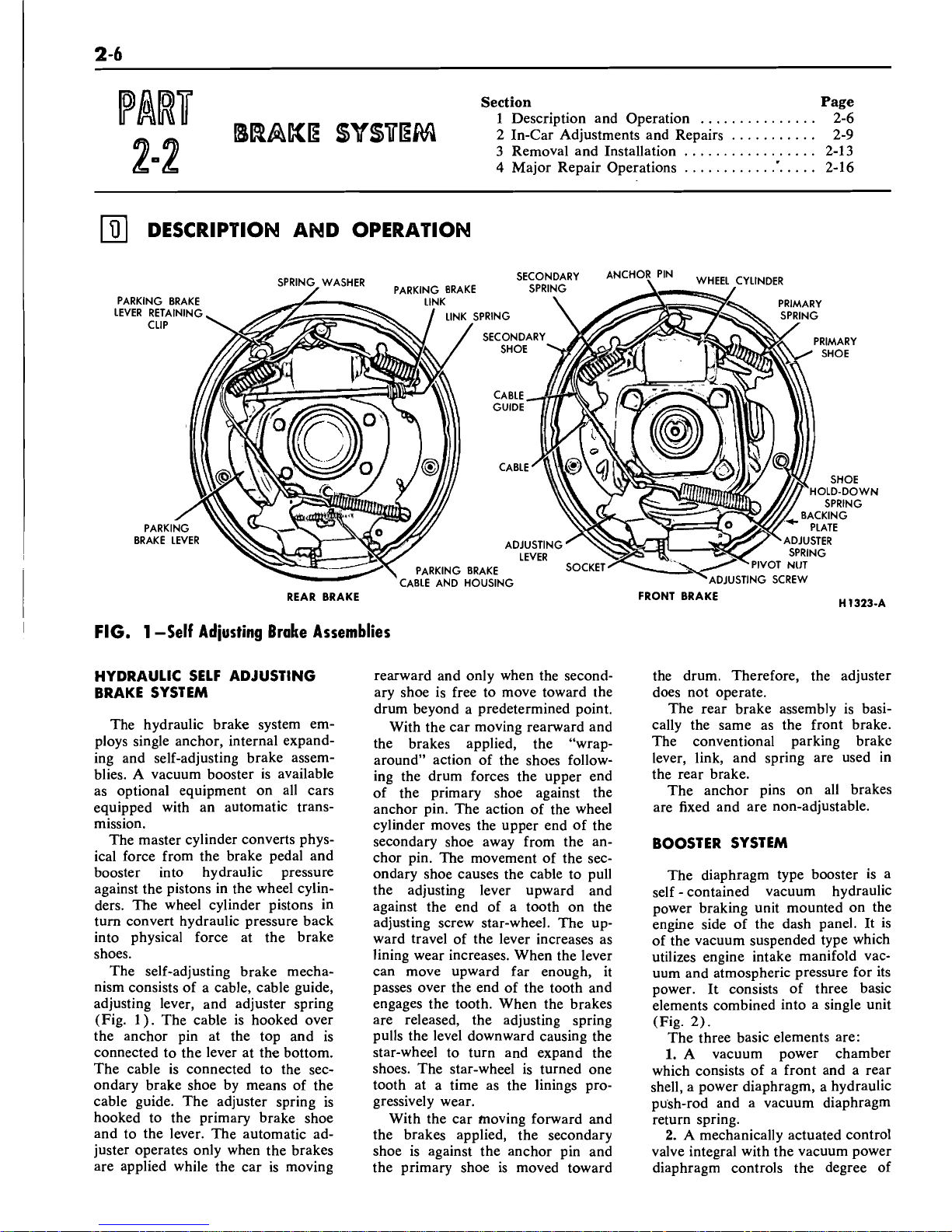
FIG.
1
-Self Adjusting Brake Assemblies
HYDRAULIC SELF ADJUSTING
rearward and only when the second- the drum. Therefore, the adjuster
BRAKE SYSTEM
ary shoe is free to move toward the
does not operate.
The hydraulic brake system employs single anchor, internal expanding and self-adjusting brake assemblies. A vacuum booster is available
as optional equipment on all cars
equipped with an automatic transmission.
The master cylinder converts physical force from the brake pedal and
booster into hydraulic pressure
against the pistons in the wheel cylinders. The wheel cylinder pistons in
turn convert hydraulic pressure back
into physical force at the brake
shoes.
The self-adjusting brake mechanism consists of a cable, cable guide,
adjusting lever, and adjuster spring
(Fig.
1). The cable is hooked over
the anchor pin at the top and is
connected to the lever at the bottom.
The cable is connected to the secondary brake shoe by means of the
cable guide. The adjuster spring is
hooked to the primary brake shoe
and to the lever. The automatic adjuster operates only when the brakes
are applied while the car is moving
drum beyond a predetermined point.
With the car moving rearward and
the brakes applied, the "wraparound" action of the shoes following the drum forces the upper end
of the primary shoe against the
anchor pin. The action of the wheel
cylinder moves the upper end of the
secondary shoe away from the an-
chor pin. The movement of the secondary shoe causes the cable to pull
the adjusting lever upward and
against the end of a tooth on the
adjusting screw star-wheel. The up-
ward travel of the lever increases as
lining wear increases. When the lever
can move upward far enough, it
passes over the end of the tooth and
engages the tooth. When the brakes
are released, the adjusting spring
pulls the level downward causing the
star-wheel to turn and expand the
shoes. The star-wheel is turned one
tooth at a time as the linings progressively wear.
With the car moving forward and
the brakes applied, the secondary
shoe is against the anchor pin and
the primary shoe is moved toward
The rear brake assembly is basi-
cally the same as the front brake.
The conventional parking brake
lever, link, and spring are used in
the rear brake.
The anchor pins on all brakes
are fixed and are non-adjustable.
BOOSTER SYSTEM
The diaphragm type booster is a
self-contained vacuum hydraulic
power braking unit mounted on the
engine side of the dash panel. It is
of the vacuum suspended type which
utilizes engine intake manifold vacuum and atmospheric pressure for its
power. It consists of three basic
elements combined into a single unit
(Fig.
2).
The three basic elements are:
1.
A vacuum power chamber
which consists of a front and a rear
shell, a power diaphragm, a hydraulic
pu'sh-rod and a vacuum diaphragm
return spring.
2.
A
mechanically actuated control
valve integral with the vacuum power
diaphragm controls the degree of
PART
2-2-BRAKE
SYSTEM
2
-7
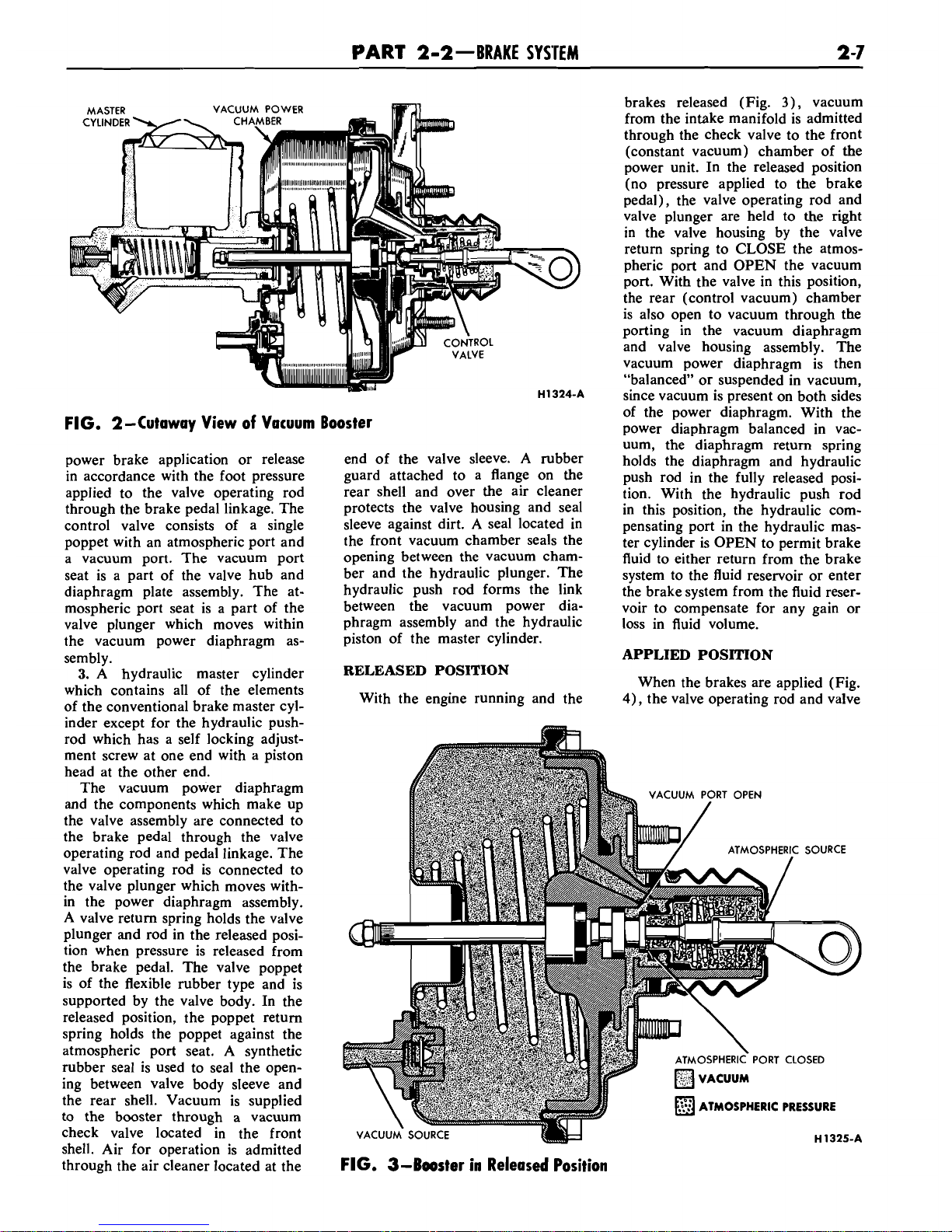
FIG. 2-Cutaway View of Vacuum
power brake application or release
in accordance with the foot pressure
applied to the valve operating rod
through the brake pedal linkage. The
control valve consists of a single
poppet with an atmospheric port and
a vacuum port. The vacuum port
seat is a
part of the valve hub and
diaphragm plate assembly. The atmospheric port seat is a part of the
valve plunger which moves within
the vacuum power diaphragm assembly.
3.
A hydraulic master cylinder
which contains all of the elements
of the conventional brake master cyl-
inder except for the hydraulic
pushrod which has a self locking adjustment screw at one end with a piston
head at the other end.
The vacuum power diaphragm
and the components which make up
the valve assembly are connected to
the brake pedal through the valve
operating rod and pedal linkage. The
valve operating rod is connected to
the valve plunger which moves within the power diaphragm assembly.
A valve return spring holds the valve
plunger and rod in the released posi-
tion when pressure is released from
the brake pedal. The valve poppet
is of the flexible
rubber type and is
supported by the valve body. In the
released position, the poppet return
spring holds the poppet against the
atmospheric port seat. A synthetic
rubber seal is used to seal the opening between valve body sleeve and
the rear shell. Vacuum is supplied
to the booster through a vacuum
check valve located in the front
shell. Air for operation is admitted
through the air cleaner located at the
Booster
end of the valve sleeve. A rubber
guard attached to a flange on the
rear shell and over the air cleaner
protects the valve housing and seal
sleeve against dirt.
A
seal located in
the front vacuum chamber seals the
opening between the vacuum chamber and the hydraulic plunger. The
hydraulic push rod forms the link
between the vacuum power diaphragm assembly and the hydraulic
piston of the master cylinder.
RELEASED POSITION
With the engine running and the
brakes released (Fig.
3),
vacuum
from the intake manifold is admitted
through the check valve to the front
(constant vacuum) chamber of the
power unit. In the released position
(no pressure applied to the brake
pedal), the valve operating rod and
valve plunger are held to the right
in the valve housing by the valve
return spring to CLOSE the atmos-
pheric port and OPEN the vacuum
port. With the valve in this position,
the rear (control vacuum) chamber
is also open to vacuum through the
porting in the vacuum diaphragm
and valve housing assembly. The
vacuum power diaphragm is then
"balanced" or suspended in vacuum,
since vacuum is present on both sides
of the power diaphragm. With the
power diaphragm balanced in vacuum, the diaphragm return spring
holds the diaphragm and hydraulic
push rod in the fully released position. With the hydraulic push rod
in this position, the hydraulic compensating port in the hydraulic master cylinder is OPEN to permit brake
fluid to either return from the brake
system to the fluid reservoir or enter
the brake system from the fluid reservoir to compensate for any gain or
loss in fluid volume.
APPLIED POSITION
When the brakes are applied (Fig.
4),
the valve operating rod and valve
VACUUM PORT OPEN
/
ATMOSPHERIC SOURCE
I
ATMOSPHERIC
PRESSURE
FIG. 3-Booster in Released Position

GROUP
2-BRAKES
the counter force reacts through the
valve plunger, valve operating rod,
and pedal linkage against the driver's foot. This reaction force is in
direct proportion to the hydraulic
pressure developed within the brake
system.
HOLDING POSITION
'
During brake application, the "reaction" force which opposes the
force applied by the driver, tends to
close the atmospheric port. When
both atmospheric and vacuum ports
are CLOSED, the booster is said to
be
in
the holding position. With both
valves closed, any degree of brake
application attained will be held until either the atmospheric port is
reopened
by an increase , in pedal
C PORT OPEN
pressure to further increase the brake
application or by a decrease in pedal
pressure to
reopen
the vacuum port
PRESSURE
to decrease the brake application.
Whenever the pressure applied to
"1326-A
the brake pedal is held constant for a
moment, the valve returns to its
holding position. However, upon
plunger move to the left in the power
and the valve plunger in proportion
the
position
diaphragm assembly to compress the to their respective contact areas. The the
the
brake
pedal
valve return spring and bring the pressure acting against the valve overmles the reaction force- In this
poppet valve into contact with the plunger and valve operating rod position the valve plunger and at-
vacuum valve seat
in
the valve hous- tends to move the valve plunger
mospheric
seat are
held
ing to "CLOSE the vacuum port. slightly
to
the right in relation to
from the valve Poppet to admit maxi-
Any additional movement of the the diaphragm and valve housing
mum
atmosphere Pressure to the rear
valve operating
iod in the applied di- assembly to close off the atmospheric
(right) chamber. With the
rection moves thevalve plunger away
port. The driver is thus assured a
(left) chamber open to manifold
from the poppet valve to "OPEN"
"feel" of the brake, since part of
vacuum, full power application, is
the atmospheric port and admit
atmosphere through the air cleaner
and passages in the diaphragm
plate to the right side of the power
chamber. With vacuum present on
the left side of the diaphragm and
VACUUM PORT
-
valve housing and atmospheric pressure present on the right side of the
ATMOSPHERIC
SOURCE
diaphragm, a force is developed to
move the vacuum power diaphragm
,
assembly, hydraulic push rod and
hydraulic piston to the left to close
the compensating port and force hydraulic fluid under pressure through
-
the residual check valve and brake
tubes into the brake wheel cylinders.
As hydraulic pressure is developed in
the hydraulic cylinder, a counter
force (to the right) acting through
the hydraulic push rod, sets up a reaction force against the vacuum
power diaphragm and valve plunger
through the rubber reaction disc (located at the end of the hydraulic
push rod). The rubber reaction disc
acts similar to a column of fluid to
distribute the pressure between the
H
1327-~
vacuum power diaphragm assembly
FIG.
5-Booster in Holding Position
 Loading...