

Ford 1963 Galaxie, 1963 Fairlane, 1963 Thunderbird, 1963 Falcon, 1963 Econoline Service Manual
...
www.carburetor-manual.com
Would you like some Free Manuals?
http://carburetor-manual.com/free-shop-manual-club-t-13.html
Also visit http://freeshopmanual.com for more Free Manuals
Also Visit my website for 7 FREE Download Manuals starting
with this one.
"The ABC's of Carburetion"
Click Here Now
file:///C|/Documents%20and%20Settings/Tim/Desktop/carburetor-manual-welcome/index.htm[4/25/2009 11:42:20 AM]
1963
FORD
SERVICE
SPECIFICATIONS
TRUCK
, ECONOLlNE, FALCON
BUS
AND FALCON
CLUB
WAGON
GALAXIE, FAIRLANE,
FALCON AND THUNDERBIRD
SERVICE
DEPARTMENT
FORD
D .
IVISIO
N
Qio..;>
MOTOR
COMPANY
FIRST PRINTING -
SEPTEMBER
1962
@
1962
FORD
MOTOR
COMPANY'
DEARBORN
, MICHIGAN

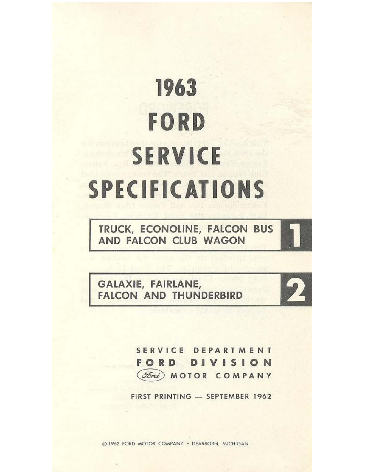
FOREWORD
This
booklet
conta
ins service specifications for
the 1963 Ford Galaxie,
Fairlane,
Thunderbird,
Falcon,
Econoline, Falcon
Station
Bus, Falcon
Club
Wagon
and
Truck.
The
booklet
is
divided
into
two
main
parts
as
indicated
on
the
title
page.
Part
1 covers
the
Ford
Truck,
Econoline,
Falcon
Station
Bus
and
Falcon
Club
Wagon.
Part
2
cove
"s
the
Ford
Galaxie,
Fairlane,
Thunderbird
and Palcon.
The
specifications contained in this
booklet
were in effect
at
the
time
the
booklet
was
approved
for
printing.
The
Ford
Division
of
Ford
Motor
Company
reserves
the
right
to
discontinue
models
at
any
time,
or
change
specifications 0" design,
without
notice
and
without
incurring
obligat
ion,
Ca
rl
T. Doma"
National Se rvice Manager
FORD DIVISION
I"ord
Motor Company

1963
FORD SERVICE
SPECIFICATIONS
PART
l-TRUCK,
ECONOLlNE,
FALCON
BUS
AND
FALCON
CLUB
WAGON
SECTION
PA
GE
1.
Engines ..
................
.......
.........
.....
...
1-4
2.
Ignition Syste m
and
Governors
.............
1-13
3.
Fuel System .
............
...
...
...
.......
........ 1-16
4. Cool ing System
...........
...............
..
....
1-19
5.
Clutches .
...................
..
...................
1·19
6. Manual-Shift Transmissions
....
............
.. 1·20
7. Aut
omat
ic Trans m
iss
ions
.......
.. .
........
... 1-2 1
8. Rear
Ax
les
..................
....
................
1
·27
9. Chassis Suspension
............................
1·34
10. Steer
ing
...........................
....
......... . 1
-36
11
. Brakes .. ....... .. .. ... ..
.......
..............
.... 1·37
12. Electrical ......
.........
...
...
..................
. 1-38
13.
Re
fill
Capac
ities
.............
......
...........
.. 1-46
NOTE:
All
specifica
tions a re given
in
inches.
unless oth
erw
ise indicated.
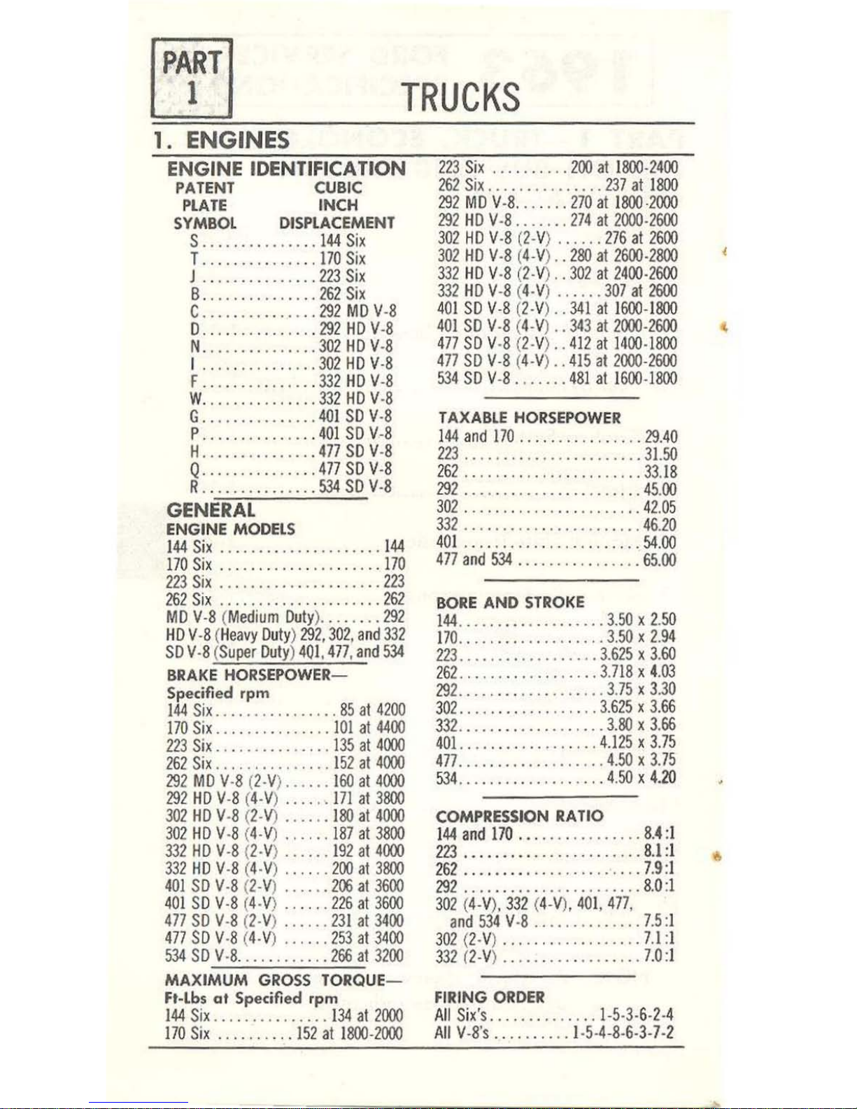
TRUCKS
1.
ENGINES
ENGINE IDENTIFICA
liON
PATENT CUBIC
PL
ATE
INCH
SYMBOL DISPLACEME
NT
S .. .. .. ..
...
.. . .
144
Six
T .....
.......... 170
Six
J ..
...•••.•.....
223
Six
B ..
...
..........
262
Six
C
....
..•..•...
..
292
MD
V-8
D .. ....
.........
292HDV-8
N .
..........
....
302
HDV-8
1 ..•.•
••.
.••
•. •• 30
2HDV-8
F .. ..
........
...
332
HDV-8
W
........
...
....
332
HD V-8
G .
...
...
........ 401 SD V·8
P .
..............
401 SDV-8
H
....
.. ....
...
..
477
SD V
-8
Q
.....
.. ..
....
..
477
SD V-8
R .......
....... .
534
SD
V·8
GENERAL
ENGINE MODELS
1
44
Six
.. ..
.. ..
...........
.. 144
170 Six ....
........
..
.......
170
223
Six
...............
. .....
223
262
Six
.. .. .. ...............
262
MD
V·8 (
Medium Duly) ........
292
HD V -8 (Heavy Duly) 292. 30
2, a
nd
332
SD V-8 (
Super
Dul
y) 401. 4
77. and
534
BRAKE
HORSEPOWER-
Specifi
ed rpm
144
Six
................
85
al
4200
170
Six
.. ..
...........
101
al
4400
223
Six
...............
135
al 4000
262
Six
...............
152 al
4000
29
2 MD V
-8
(2-
V)
......
160
al
4000
292
HD V-8 (
4-V
) .
...
..
171
al
3800
302
HD
V-8 (2
-V)
......
1
80
al
4000
302
HD V-8 (4·
V) ... . . .
187
al
3800
332
HD
V-8 (2·V) ...
... 192
al
4000
332 HD
V-8 (4-V) ..
....
200
al
3800
401
SO
V·8 (2-V) ......
2~
al
3600
401
SD
V-8 (4-V) .... ..
226
al
3600
477
SD
V-8
(2·
V)
...... 231
al 3400
477
SD
V·8 (4-
V) ....
..
253
al 3400
534
SD
V -8 ... ..
.......
266
al 3200
MAXIMUM
GROSS TORQUE-
Ft-lbs at Spe
cifi
ed
rpm
144
Six
...............
1
34
al
2000
1
70
Six ....
...
.. .
152
al
1800-2000
123 Six ..
.....
.. .
200
al 1800-2400
262
Six
...............
237
al 1800
292
MD
V-8 . .. ....
170
al 1800·2000
292
HD V·8
.....
..
274
al
2000-2600
302
HD
V-8
(2-V) ..
.... 276
al
2600
302 HD
V-8 (4-V) ..
280
al
2600-2800
331
HD
V-8 (2-
V)
. .
302
al
2400·2600
332
HD V-8 (
4-V
) _ ..
...
307
al
2600
40
1 SD V-8 (2-V)
..
341
al 1600-1800
401 SO V·8 (4.V)
.. 343
al
2000-2600
477
SD V·8 (2-V) ..
412
al 1400-1800
477
SD
V-8
(4
-V)
..
415
al
2000-2600
534 SO
V-8
....... 481
al 1
600-1800
TAXABLE HORSEPOWER
1
44 and 1
70
............
....
29.40
223
.......................
31.50
262
...
. .. ....
...........
..
33.18
292
.......
..
....
.. _ ....... 45.
00
302
...
....
.......
..
....
...
42.
05
332
.......................
46.20
401 .. . . ..
...............
..
54.00
477
and
534
.. .
....
.....
....
65.00
BORE
AND
STROKE
144
.....
...
........... 3.5
0 x
2.50
1
70
.. . ..
...
.. .
........ 3.50 x 2.94
223 ..................
3.615
x 3.
60
162
..............
.. .. 3.718
x 4
.03
292
...................
3
.75 x 3.30
302 .........
.. .
......
3.625
x 3.
66
332 .....
..............
3.80 x 3.66
40
1.
........ ..
. _ ..
... 4.125 x 3.75
477
...
....
...
.........
4.50 x 3.
75
534
.......
..
.....
..... 4.
50
x
4_20
COMPRESSION RATIO
144 and 170
................
8.4:
1
2
23 ................
" .
.. .. 8.1:
1
262 .....
....
.........
.. . .. 7.
9:1
292 ..........
.............
8.
0:1
301
(4-V).
332
(4-V).
40
1,
477
.
a
nd
534
V·8
.............
. 7.5
:1
302
(2-V) .
...
.. .
...
.. ...... 7.1:1
332
(2-V)
..................
7.0
:1
FIRING
ORDER
All Six·s
............
.. 1-5-3-6-2
-4
All
V-8·s ..
........
1-5-
4-8-6-3
-7-2
,
ENGINES
1-5
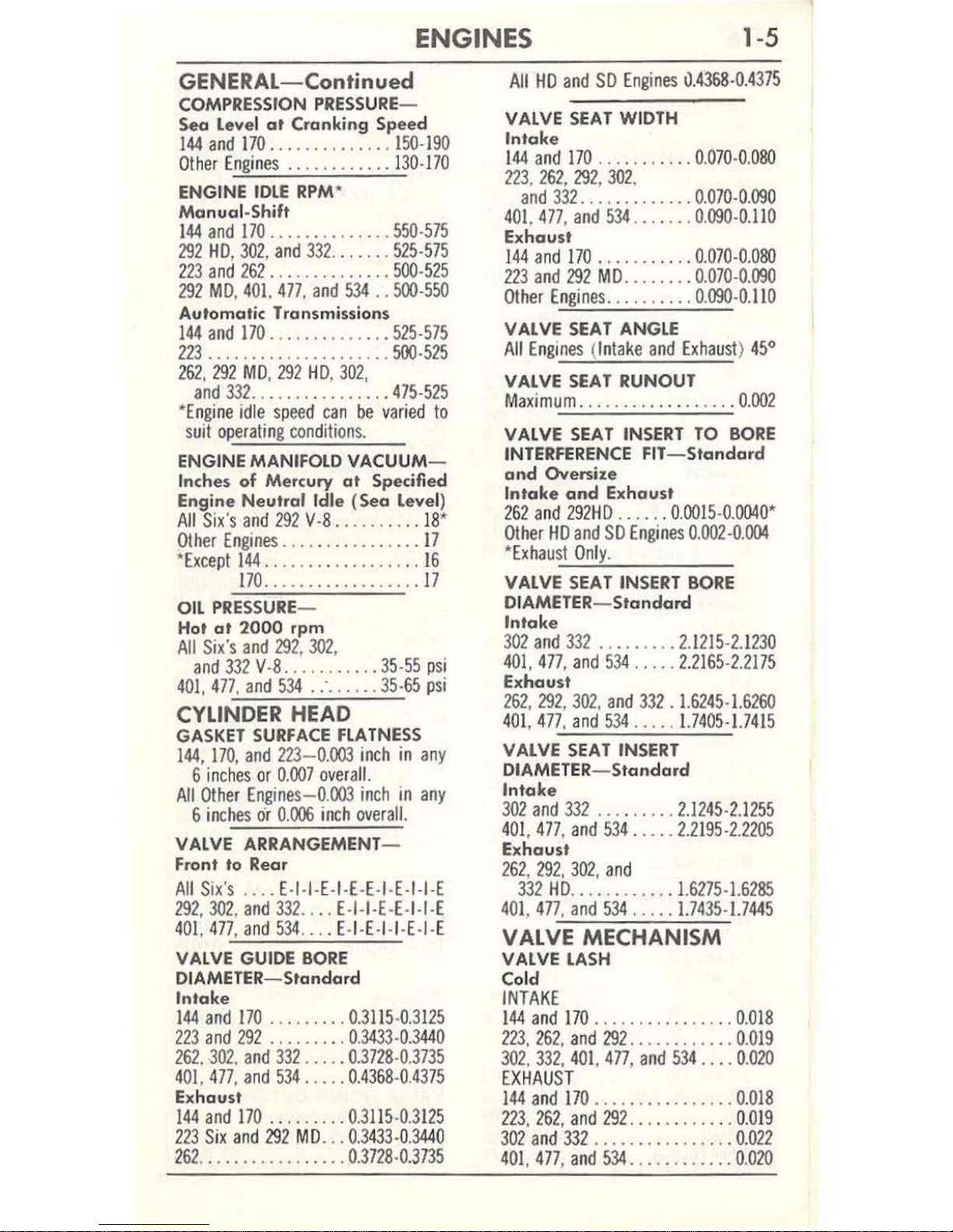
GENERAL-Continued
COMPRESSION
PRESSURE
-
Sea
Level at
Cranking Speed
144
and
170
...
...........
150·190
Other Eng
ines ............
130·170
ENGINE
IDLE
RPM
'
Manual-Shift
144
and
170 ..............
550·575
292 HD,
302, and
332
.......
525·575
223
and
262 ...........
.
..
500·525
292
MD, 401.
477
,
and
534
..
500·550
Automatic Transmission s
144
and
170
..............
525·575
223
.....................
500·525
262,
292
MD, 292
HD,
302,
and
332
................
475·525
""
Engine
idle
speed
can
be
varied
to
suit
operating
conditions.
ENGINE
MANIFOlD
VACUUM
-
Inches of Mercury
at
Specified
Engine Neutral
Idle (Sea
level
)
A
ll
Six's
and
292 V·8 ......
.... 18'
Olher
Engines
................
17
'
Excepl
144
..................
16
170
..................
17
OIL
PRESSURE
-
Hot
at
2000
rpm
All
Six's
and
292,
302
,
and
332 V·8
...........
35·55
psi
401,
477
,
and
534
. c
......
35·65
psi
CYLINDER
HEAD
GASKET
SURFACE
FlATNESS
144, 170,
and
223-0.003
inch
in
any
6
inches
or
0.007
ove
ral
l.
All
Other Engines
-O.OO3
inch
in
any
6 inches
or
0.006
inch
overall.
VALVE ARRANGEMENT-
Front to Rear
All
Six's
....
E·I·I·E·I·E·E·I·E·
I·I
·E
292,302, and
332 .... E·I·
I·E
·E·I·I·E
401.
477
,
and
534 ....
E·I
·E·
I·I·E·
I·E
VALVE GUIDE
BORE
DIAMETER- Standard
Intake
144
and 170
.........
0.3115·0.3125
223
and
292 .......
..
0.3433·0.3440
262,
302, and
332 .....
0.3728·0.3735
401,
477,
and
534
.... .
0.4368·0.4375
Exhaust
144
and
170
.. . , .
.... 0.3115·0.3125
223
Six
and
292
MD
. ..
0.3433·0.3440
262
.................
0.3728·0.3735
All
HD
and
SO
Engines
0.4368·0.4375
VALVE
SEAT
WIDTH
Intake
144
and
170
.......
.... 0,070·0.0BO
223, 262,
292, 302.
and
332
....
....
.....
0.070·0.090
401,477, and
534
.....
.. 0.
090·0.110
Exhaust
144
and
170
. .......
...
0.070·0.0BO
223
and
292
MD
........
0.070·0.090
Other
Engines
.......... 0.090·0.110
VALVE
SEAT
ANGLE
All
Engines (In
lake
and
Exhausl
) 45·
VALVE
SEAT
RUNOUT
Maxi
mum ........
......
.... 0.002
VALVE
SEAT
INSERT
TO
BORE
INTERFERENCE
FIT-S
tanda
,d
and Oversize
Intake
and
Exhaust
262
and
292
HD .
.....
0.0015
·0.004
0'
Other
HD
and
SO
Engines
0.002·0.004
'
Exhaus"'I..:O"nl"-y.
____
_
VALVE
SEAT
INSERT
BORE
DIAMETER-
Standam
Intake
302
and
332
.. .
......
2.1215·2.1230
401,
477,
and
534
.....
2.2165·2.2175
Exhaust
262,
292,
302,
and
332 . 1.6245·1.6260
401,477,
and
534
.....
1.7405·1.7415
VALVE
SEAT
INSERT
DIAMETER- Standard
Intake
302
and
332
...... , ..
2.1245·2.1255
401,477, and
534
.....
2.2195·2.2205
Exhaust
262, 292,
302,
and
332
HD
..........
, .
1.6275·1.6285
401,
477
, a
nd
534
.....
1.74
35·
1.7445
VALVE MECHANISM
VALVE
LASH
Cold
INTAKE
144
and
170
.......
, .. .
...
..
O.oI8
223,
262,
and
292
............
O.oI9
302,
332,
401,
477, and
534
.... 0.020
EXHAUST
144
and
170
................
0.018
223,
262,
and
292
............
0.019
302 and
332
.........
.......
0.022
401,477,
and
534
............ 0.020
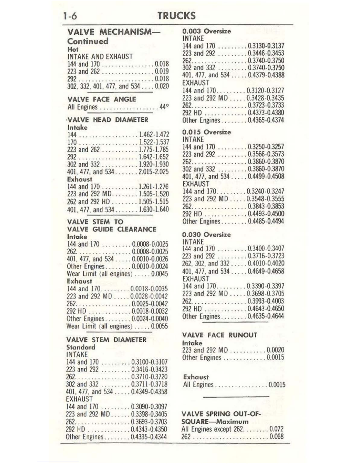
1-6
TRUCKS
VALVE
MECHANISM-
Continued
HoI
I
NTAKE
AND
EXHAUST
144
and
170
................ 0.018
223 and
262 ............
. _ . _ 0.
019
292
____ . ______
....... _ .... 0.018
302.332.401.477. and
534
.. _.0_
020
VALVE
FACE
ANGLE
All
Engines
. _.
_.
__
. _
....
__
. _ . 44'
·VALVE HEAD DIAMETER
Intake
144
...
_. _. _. _ ....... _ 1.462-1.472
170
_. _ ..
___
... _
.... _.1.522-1.5
37
223
and
262
_.
_. _ ..... .
1.775-1.785
292
...
......
.. _. _
....
1.642-1.652
302
and 332
_____
. _ ....
1.920-1.930
401.477. and
534
_ ..
...
. 2.015-2.
025
Exhaust
144
and
170
___ ..
____
..
1.261-1.276
223
and
292
MD
.....
___
1.505-1.520
262
and
292
HD _.
_. _ ... 1.505-1.515
401
.
477
.
and
534 .... _ ..
1.630-1.640
VALVE
STEM
TO
VALVE GUIDE CLEARANCE
Intake
144
and
170
___
. _ ....
0_0008
-0.
0025
262
__
.. _ ....
_ . _ . _
.. _ 0_0008
-0.
0025
401.
477
. and
534
. _
...
0.0010-0.0026
Other Engines
. __ .
__
. _
0.0010
-0.
0024
Wear
Limi
t (
all
engines) ..... 0.0045
Exhaust
144
and
170. _. _ ..... 0.0018
-0.0035
223 and
292
MD
_ ..
_.0.0028-0.0042
262
___ .
__ __ . __
..
_ . _ .0.
0025
-0.
0042
292
HD _
....
...
_ .
___
0_0018
-0_
0032
Other Engines
________ 0_0024-0_0040
Wear
l i
mit (all engines
) __
___ 0_0055
VALVE
STEM DIAMETER
Standard
INTAK
E
144
and
170
____
.....
0.3100-0.3
107
223
and
292 .........
0.34
16-0_
3423
262
..
____ . _.
__
. _ .
__ .0.3
710-0.3
720
302
and
332
__ ......
_ 0.3711-0.3
718
401.477. and
534
... _.0.4349
-0.
4358
EXHAUST
144
and
170 .........
0.3tBO-0.3tB7
2
23
and 292
MD
_ .
___
. 0
.3398-
0.3405
161_ ...............
_
0.3693-0.3703
291
HD _ ........
__
..
0.4343
-0.
4350
Other
Engine
s.
_ .
.....
0.4335
-0.
4344
0.003
Oversize
INTAKE
144 and 170
... _ . _ .. _
0.3130-0.3137
123
and
291
_ .. ___ . _ .0.
3446-0.3453
262
. _ ..
..
_ . _ . _ .
..
__ .0.3740-0.3750
302
and
332
...
.. _
...
0.3740-0.3750
401. 477.
and
534
. _ • _ .
0.4379-0_4388
EXHAUST
144
and
170
. _ ... _ ...
0.3120-0.3127
223
and
292
MD
... __
0.3428-0.3435
262.
____
__ . ____
... _
.0.3723-0.3733
292
HD
. _
.....
__ . _
..
0.4373-0_4380
Other
Engines
. _____
..
0.4365-0_4374
0.
015
Oversize
IN
TAK
E
144
and
170 ... ___ . _.
0.3250-0.3257
223 and
291 ___ ..
____ 0.3566-0.3573
262
____ . _
__
...
. _ . _ ..
0.3860-0.3870
302
and
332
. _ . _ .. _ . _
0.3860-0.3870
401,
477,
and
534
. _ .. _
0_4499-0.4508
EXHAUST
1
44
and
170
.... _. _ ..
0.3240-0.3147
113
and
292
MD.
_ .
.. 0.3
548-0.3555
262
__
. _ . _
__
.....
....
0.3843-0.3853
291
HD
. __ .... ______
0_4493-0_4500
Other Eng
ines ___
. _ . _ . 0_
4485-0.4494
0.030 Oversize
INTAKE
144
and 170
____
. _
...
0.3400-0.3407
2
23
and
292
.......
__
0.3716-0.3723
262. 302.
and 332
_ . _ . _ 0_
4010
-0.
4020
401, 477, and
534
. _ .
__
0.4649-0_4658
EXHAUST
1
44
and
170
........ _ 0.3390-0.3397
223
and
292
MD
. _
.. _ 0.3698-0.3
705
262
_ . _ .. _ .
__
. _ . ___ .. 0.
3993-0.4003
292
HD
. _.
__ ..... ...
0.4643-0.4650
Other Engines
. _ .
__
. _ .
0.4635-0.4644
VALVE
FACE
RUNOUT
Intake
223
and
292
MD
. _ ..
__ .... _
0.0010
Othe
r En
gines ______
. _
..... 0_0015
Ex
haust
All
Engines
__
. _ . _ .
___
.....
_ 0.
0015
VALVE SPRING OUT -OF-
SQUARE-Maximum
All
Engines
except
262 ........ 0.072
262
_ . _
...
..
___
. __
...
..... _ 0.
068

ENGINES
1-7
VALVE
MECHANISM-
Continued
VALVE
SPRING
FREE
LENGTH-
Approximate
144
aad
170
...... ' ........
..
2.00
262
........................
1.96
401,477,
and
534
......
....
...
2.07
Other
Engines
......
...
......
2.00
VALVE
SPRING
PRESSURE-
Pounds at Specified Length
Valve
Closed
144
and
170
....
47.75·56.25
at
1.585
Wear
Lim
it
43
at
1.585
262
....
.............
71·79
at
1.65
Wear
Limit
64
at
1.65
401, 477,
and
534 .....
84·89
at
1.70
Wear
Limit
76
at
1.70
Other
Engines
......
..
71
·79
at
1.78
Wear
Dmit
64
at
1.78
Valve Open
144
and
170
.......
112·122
at
1.222
Wear
Limit
101
at
1.222
262
..............
161·177
at
1.260
Wear
Limit
145
at
1.260
401,477,
and
534
....
178·192
at
1.28
Wear
Limit
161
at
1.28
Other
Engines
......
161·177
at
1.39
Wear
Limit
145
at
1.39
VALVE
SPRING
ASSEMBLED
HEIGHT
-Pad
to Retainer
144
and
170
....... 1·9/16
- 1·39/
64
262
.. ..
...........
1·5/
8-1·11/16
401,477,
and
534
.. 1·11
/16-1.23/
32
Other
Engines
......
1·3
/4-
1·25/32
VALVE
PUSH
ROD
RUNOUT-
Maximum
All
Engines
.................
0.
025
ROCKER
ARM
SHAFT
0.0.
144, 170,
223, 262,
292. 302
,
and
332 .......
..
....
0.780·0.781
Other
Engines
........
..
0.781·0.782
VALVE
TAPPET
DIAMETER-
Standard
223.
.... . .
.......... 0.4983·0.4989
292
and
262
......... 0.4989·0.4995
144,170,302,332,401.
477
and
534
...
......
.. 0.
8740·0.8745
VALVE
TAPPET
TO
TAPPET
BORE
CLEARANCE
223.
. .
...
...........
0.
0011·0
.0027
Wear
Limit 0.0055
262
and
292
......
. .. 0.
0005·0.0021
Wear
Li
mit
0.0055
Other
Engines ....
....
0.0005·0.0020
Wear
Limit
0
.005
ROCKER
ARM
TO
ROCKER
SHAFT
CLEARANCE
144
and
170
.......... 0.002·0.0045
Wear
Limit
0.006
223,
262,
and
292
...
. ..
0.002
·0.004
Wear
Limit
0.007
302
and
332
....... ' ...
0.002
·0.
004
Wear
Limit
0.008
401.
477
,
and
534
.....
.. 0.
001·0.003
Wear
Limit
0.007
ROCKER
SHAFT
BORE
DIAMETER
All
Engines
............
0.783·0.784
CAMSHAFT,
TIMING
CHAIN,
AND
TIMING
GEARS
CAMSHAFT
END
PLAY
All
Engines
............
0.
001
·0.
007
Wear
Limi
t 0.
012
CAMSHAFT
JOURNAL
TO
BEARING
CLEARANCE
All
Engines
.......
....
. 0.
001
·0.
003
Wear
Limit
0.006
CAMSHAFT
JOURNAL
RUNOUT
All
Engines
.................
0.005
CAMSHAFT
JOURNAL
OUT
·Of·ROUND
144, 170,262,302,332,
401,477
and
534
.................
0.0005
223
and
292
................
0.001
CAMSHAFT
LOBE
liFT
Intake
144
and
170
...............
0.
2405
223
and
262
................
0.
273
292 ...
............
........
0.264
302
and
332
................
0.244
401,477
.
and
534
............
0.278

1-8
TRUC
KS
CAMSHAFT,
TIMING
CHAIN,
AND
TIMING
GEARS
-
Continued
Exhau.st
144 and 170
...............
0.2395
223
and
262
................
0.
273
292
.......................
0.
262
302 and
332
................
0.
265
40
1.
477
.
and 534 ............
0.
278
LOBE
LIFT
lOSS- Maximum
Intake
and Exhaust
..........
0.005
CAMSHAFT GEAR
TO
CRANKSHAFT GEAR BACKLASH
26
2.
302.
332. 401.
477
.
a
nd
534
.............
0.
002
·0.
004
ASSEMBLED
SPROCKET
OR
GEAR F
ACE
RUNOUT
1
44.
170.
223. 262. and
292
.... 0.006
O
ther Engin
es ....
...........
0.
001
TIMING CHAtN DEFLECTION
1
44.
170.223.
and
292
..........
0.5
CAMSHAFT JOURNAL
DIAMETER- Standard
1
44 and
170
.........
1.8095·1.8105
223.
262. and
292
....
1.9255·1.9265
302
and
332
.........
2.1238·2.1248'
401.
477
.
and
534
......
2.370·2.3
71'
Front Journal
302
and
332
.........
2.4738
·2.
4748
40
1.
477.
and
534
....... 2.474·2.475
-Nos. 2.
3.
4.
and 5 journals
only
.
CAMSHAFT
BEARINGS
INSIDE DIAMETER-
ASSEMBLED
144
and 1
70
..........
1.8115· 1.81
25
223.262
. and
292
.....
1.9275·1.9285
302
and
332
..........
2.
126
·2.
127'
40
1.
477.
and
534
......
2.372·2.373'
-Nos. 2.
3.
4.
and 5 bearings onl
y-
No
. 1
bearing 2.476
·2.
477
LOCATION
IN
RElATiON
TO
FRONT
FACE
OF
BLOCK
CAM
BEARING
BORE
- No. 1 Bearing
Only
1
44 and 170
...........
0.
115·0.125
223.262.292.302.
and
3320.
005
·0.
020
4
01.
477
. a
nd
534
.......
0.3
10·
0.330
FLYWHEEL
ASSEMBLED
FLYWHEEl CLUTCH
F
ACE
RUNOUT
All Engm
es
.................
0.010
ASSEMBLED
FLYWHEEl
O.
D. RUNOUT
144.
223. 262.
and
292
........
0.007
Ot
her
Engm
es ...............
0.006
CRANKSHAFT
MAIN
BEARING JOURNAL
DIAMETER- Standard
144 and 170
...
......
2.2482·2.
2490
223
and
292
......... 2.4980·2.4988
2
62
..............
... 2.4976
·2.
4984
302 and
332
......
..
2.6230·2.
6238
401.
477
.
and
534
..... 3.1246·3.1254
CON NECTING ROD JOURNAL
DIAMETER ,
1
44
and
170
.........
2.1232·2.1240
223
and
262
.........
2.2980
·2.
2988
292
..........
.......
2.1
880·2.1888
302
and
332
......... 2.2482 ·2.2490
401.
477
.
and
534
.....
2.7092·2.7100
MAIN
BEARING JOURNAL
RUNOUT
144and 170
..
0.0025·Wear Lim
it 0.0035
223
and
262
..
O.OO3·Wear
Lim
it
0.004
292
.. .
......
0.002·Wear
Limit
0.003
Olher
Engine
s 0.
002·Wear Limit
0.003
CONNECTING
ROD
AND
MAIN
BEARING JOURNALS
OUT-OF-ROUND
All
Engines
................
0.0004
CONNECTING
ROD
AND
MAIN
BEARING JOURNALS
TAPER
All
Engines
................
0.
0003
THRUST
BEARING JOURNAL
LENGTH
144
and
170
............
1.275· 1.277
223
and
262
...........
1.359·1.361
292.302.
and
332
.......
1.1
24·
1.126
401.
477. and
534
.......
1.279·1.281
MAIN
BEARING
JOURNAL
THRUST
FACE
RUNOUT
A
ll
Engi
nes
.................
0.
001
ENGINES
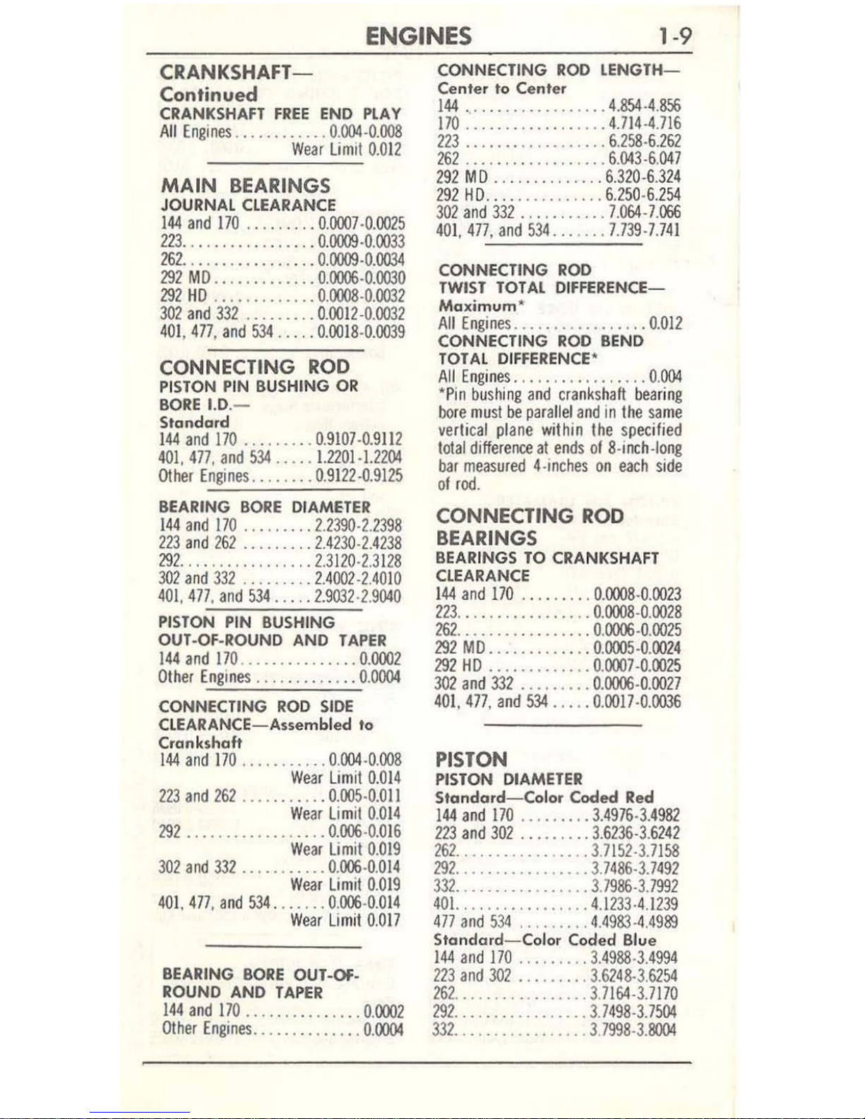
1-9
CRANKSHAFT-
Continued
CRANKSHAFT
FREE
END
PLAY
All
Engines ............
0.
004
-0.
008
Wear
Limil 0.011
MAIN
BEARINGS
JOURNAL CLEARANCE
144
and
170
.. ... .. .. 0.
0007·0.0015
113 .........
. . .... .. 0.
0009
·0.0033
161
.......
...
....
... 0.
0009·0.0034
191
MO ............
. 0.
0006·0.0030
191
HO
............
. 0.
0008
·0.
003
1
301 and 331
........
. 0.
0011
·0.0031
401, 477, and
534 .....
0.00
18·0.
0039
CONNECTING
ROD
PISTON PIN BUSHING
OR
BORE
1.0
.-
Standard
1
44
and
170
......... 0.9107·0.9111
401,477, and
534
.....
1.1101·1.1104
Oth
er
Engin
es
........ 0.9111
·0.
9115
BEARING BO
RE
DIAMHER
144
and 170
.......
..
1.1390·1.1
398
113
and
162
....
...
.. 1.4130·1.4138
191
..............
... 1.3110·
1.3
118
3
01
and 331 ..
....
. ..
1.4001·1.4010
401.
477. and
534 ... .. 1.9
031·2.9
040
PISTON PIN BUSHING
OUT-Of
-ROUND AND
TAPER
144
and
170
.............
.. 0.
0001
Olher
Engines ............
. 0.
0004
CONNECTING
ROO
SIDE
CLEARANCE-Assembled
to
Crankshaft
144
and
170
........... 0.004
·0.008
Wear Lim
il
0.014
113 and 161
..........
. 0.005·0.011
Wear Limil 0.014
191
..................
0.
006
·0.016
Wear
Lim
il 0.
019
3
01
and
331
........... 0.006
·0.
014
Wear
Limil 0.019
401.
477. and
534
. ..
.... 0.006
·0.014
Wear Limil
0.017
BEARING
BORE
OU
T-Of-
ROUND AND
TAPER
144
and
170
...............
0.
000
1
Other
Engines
.............. 0.0004
CONNECTING
ROO
LENGTH-
Center
to C
enter
144
'.'
................
4.854
·4.
856
170
..................
4.714·4.7
16
1
13
..................
6.158·6.161
161
.................. 6.043·6.
047
191
MO .............. 6.310·6.314
291
H O
....
...........
6.150·6.154
301
and
332
........... 7.064
·7.
066
401.
477
,
and
534
.......
7.739·7.741
CONNECTING
ROO
TWIST TOTAL DIFFERENCE-
Max
imum
*
All
Engines .................
0.012
CONNECTING
ROO
BEND
TOTAL
DIFFERENCE
'
All
Engines
. . .
..............
0.004
"
Pin
bushing
and
crankshaft
bearing
bore
must
be pa
rallel
and
in
the
same
vertical
plane
within
the
specified
lolal
difference
al
ends of 8·inch.10ng
bar
measured 4·inches
on
each
side
of
rod
.
CONNECTING
ROD
BEARINGS
BEARINGS
TO
CRANKSHAFT
CLEARANCE
144
and
170
.... . . ...
0.0008
·0.
0013
11
3 . . . ....
.......... 0.0008
·0.
0028
161
.................
0.
0006
·0.0025
192
MO
.............
0.
0005
·0.
0024
191
HO
.............
0.
0007·0.0025
301
and
331 ......... 0.0006·0.0027
401.
477. and
534
..... 0.0017
·0.
0036
PISTON
PISTON DIAMETER
Standard- Color Coded
Red
144
and
170
.........
3.4976
·3.
4981
113
and
301
......... 3.6136
·3.
6141
162
............
.....
3.7152·3.7
158
192
.................
3.7486·3
.7491
331
.................
3.7986·3
.7991
40
1.
................
4.1
133·4.1139
477
and 534
......... 4.4983
·4.
4989
Standard- Color Coded Blue
144
and
170
......... 3.49
88·
3.4994
113 and 301
......... 3.6248·3.
6154
161
.................
3.
7164
·3.7
170
191
.................
3.7
498·3.7504
331
..............
...
3.7
998
·3.
8004

1-10
TRUCK
S
PI
STO
N-
Conti
nued
401.
................
4.1245·4.1251
477
and
534
.........
4.4995
·4.5001
0.003 Oversize
144
and
1
70
.........
3.5000·3.5006
223
and
302
......... 3.6260
·3.
6266
262
.................
3.7176·3.7
182
292
....
""
.........
3.7510·3.7516
332.
__
..............
3.
8010
·3.
8016
401.
................
4.1257·4.1263
477
and
534
.........
4.5007·4.5013
PISTON
TO
BORE CLEARANCE
- Bottom of Skirt
144
and
170
.........
0.0018·0.0036
Wear
lim it
0.008
262
.....
__
.....
.. ..
0.00
14·
0.0032
401.
477.
and
534 ____ . 0.0011·0.00
29
Wear
Umit
0
.008
All
Olher Engines
.....
0.0008·0.0026
Wear
limil 0
.008
PISTON PIN
DIAMETE
R
Standard
401.
477.
a
nd
534
.....
1.2198·1.2201
Olher
Engines ........
0.9120·0.9123
0.
001
Oversi
ze
401.
477.
and
534
.....
1.2208
·1.22
11
Other Engines rExcepl
144
and
170
1
__
...
__
' .
__
..
__
0.9130·0.9133
0.
002
Ov
ersize
401. 477.
and
534
.....
1.221
8·1.222
1
Other
Engrnes ,Excepl
144
a
nd
170
1
.................
0.
9140·0.9
143
PISTON PIN
LENGTH
144
. 1
70.223.262.
and
292
.............
3.010·3.030
302
__
................
3.008·3.028
332
..
________
.,
______
3.156·3.176
401
..................
3.335·3.350
477
and
534
...........
3.840·3.8
55
PISTON
PIN
TO
PISTO
N
CLEARANCE
401.477
. and
534
.....
0.0003·0.0005
Wear
limit
0.001
othe
r Engi
nes ........
0.0001·0.0003
Wear
limit 0.
0008
PISTON
PIN
TO
CONNECTING
ROD
BUSHING
CLEARANCE
401.477
, and
534
.....
0.0001·0.0006
other Engines (Except
1
44
and
170
)
.....
...
.........
0.0001·0.0005
Wear
lim it (
all
engines) ......
0.
001
PIST
ON
RIN
GS
SIDE CLE
ARANCE
Compression
Ring
144, 170, 223.
162
,
and
291
...........
0.
0019
·0.
0036
Wear limil
0.006
301
a
nd
332
Top
Ring .
0.0024·0.0041
Bottom
Ri
ng
.........
0.003
·0.
005
W
ear
lim
it
0
.006
401.477.
a
nd
534
Top and
I
ntermedia
te
Rin
gs
..
0.0029·0.0046
Bottom Ring
.......
0
.0025·0.004
5
Wear
lim
it
0.
006
Oil
Ring
144. 170. 223. 162.
and
292
..................
Sn
ug
302
and
332 .........
0.0018
·0.
0052
Wear lim
it
0.
007
401.477
,
and
534
..... 0.00
14·0.
0031
Wear
limit
0.007
RING
WID
TH
C
ompression
Ring
Top Ring
144,
170,261
,
and
292
.0.
0774
·0.
0781
Bottom
Ring
144
and
170
.....
....
0.0770·0.0780
123
and
162
......... 0.0929·0.0936
292
..............
...
0.0774
·0.
078
1
othe
r E
ngines
Top
and Intermediate
Rings
.............
0.0929·0.0936
Bottom
Ring
.......
0.0930·0.0940
Oil
Rin
g*
302. 331.
401.
477
.
and
534 .....
......
0.1859·0.1866
'Width
specified
is
for
one
rin
g.
Two
r
ings used
per
groove
on
302
and
332
.
RI
NG
GA
P WIDTH
Co
mpr
ession
Ring
- Standa
rd
80
..
1
44
and
1
70 ............
0.010·0.020
223.262
, and
292
........ 0.010
·0.
025
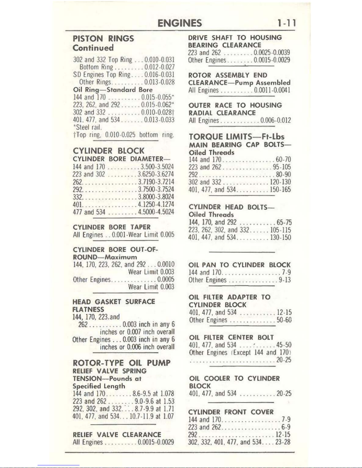
ENGINES
1-11
PISTON RINGS
Continued
302
and
332
Top
Ring
...
0.010·0.03
1
Bollom
Ring
......... 0.012
·0.
027
SO
Engines
Top
Ring ....
0.016·0.031
OIher
Rin
gs
.......... 0.013·0.
028
Oil
Ring
- Standa
rd
Bor
e
144
and
170
.......... 0.015·0.055"
223.262.
and
292
......
0.015·0.062-
302
and
332
..........
0010-0.0281
401.
477. and
534
....... 0.013-0.033
'S
leel
r,,1.
tTop
ring
. 0.
010·0.025
bollom
flng
.
CYLINDER
BLOCK
CYLINDER
BORE
DlAMETER-
144
and 170
..........
3.500·3.5024
223
and
302
......
... 3.6250
·3.
6274
262
.................
3.7190·3.7214
292
....
.............
3.7500·3.7524
332
...
.. .
...........
3.8000-3.8024
401.
................
4.
1250-4.1274
477
and
534
......... 4.5000-4.502
4
CYliNDER
BORE
TAPER
A
ll Engines
.. O.OOI-Wear
limil
0.005
CYLINDER
BORE
OUT ·OF-
ROUND- Maximum
144. 170,223. 262.
and
292
.. .
0.0010
Wear
limil
0.003
Other
Engines
..............
0.0005
Wear
lim
ll
0.003
HEAD GASKET
SURFACE
flATNESS
144,170,223,and
262
... .
......
0.003 inch
in
any
6
inches
or
0.007 inch
overa
ll
Other
Engines ...
0.003 inch
in
any
6
in
ches
or
0.006
inch over
all
ROTOR-
TYPE
OIL PUMP
RELIEF
VALVE
SPRING
TENSION
- Pounds at
Specified length
144 and
170 .....
...
8.6-9.5
al
1.078
223 and
262
........
9.0·9.6
at
1.53
292.302.
and
332
.·.·
..
8.7·9.9
al
1.71
401.
477.
and
534
...
10.7 -11.9
al
1.07
RELIEF
VALVE CLEARANCE
All
Engines
.......... 0.0015
-0.
0029
DRIVE
SHAFT
TO
HOUSING
BEARING CLEARANCE
223
and
262
.....
.... 0.0025
·0.
0039
OIher
Engines
........ 0.tX)]5-0.0029
,
ROTOR
ASSEMBLY
END
CLEARANCE- Pump Asse
mbled
All
Engines
.......... 0.0011·0.0041
OUTER
RACE
TO
HOUSING
RADIAL CLEARANCE
All
Engines
............
0.006-0.0
12
TORQUE
L1MITS
- FI-Lb.
MAIN
BEARING CAP
BOL TS-
Oiled Threads
144
and 170
................
60-70
223
and
262
...............
95·105
292 .....
.......
....
......
SO-90
302
and
332
.............. 120-
130
401,
477.
and
534
..........
150-165
CYLINDER HEAD
BOLTS
-
Oi
led Threads
144, 170, and
292
...
........
65-
75
223. 262,
302,
and
332
......
105·115
401.
447. and
534
........
..
130-150
OIL PAN
TO
CYLINDER BLOCK
144
and
170
..................
7·9
Olher
Engines
...............
9-13
OIL
FILTER
ADAPTER
TO
CYLINDER BLOCK
401.
477, and
534
......
..
...
12-15
OIher
Engines
..............
50-60
OIL
FILTER
CENTER
BOLT
401.
477.
and
534
.... , ...... 45·
50
Other
Engine
s I
Excepl
144
and 170
)
.
......
.....
......
...
.....
20·25
OIL
COOLER
TO CYLINDER
BLOCK
401.
477.
and
534
...........
20·25
CYliNDER FRONT COVER
144
and
170
...... ..
..........
7-9
223
and
262
.........
. ..
....
.. 6·9
292
.. ..
.............
.
..... 12·
15
302.332.40
1.
477.
and
534
.... 23-28
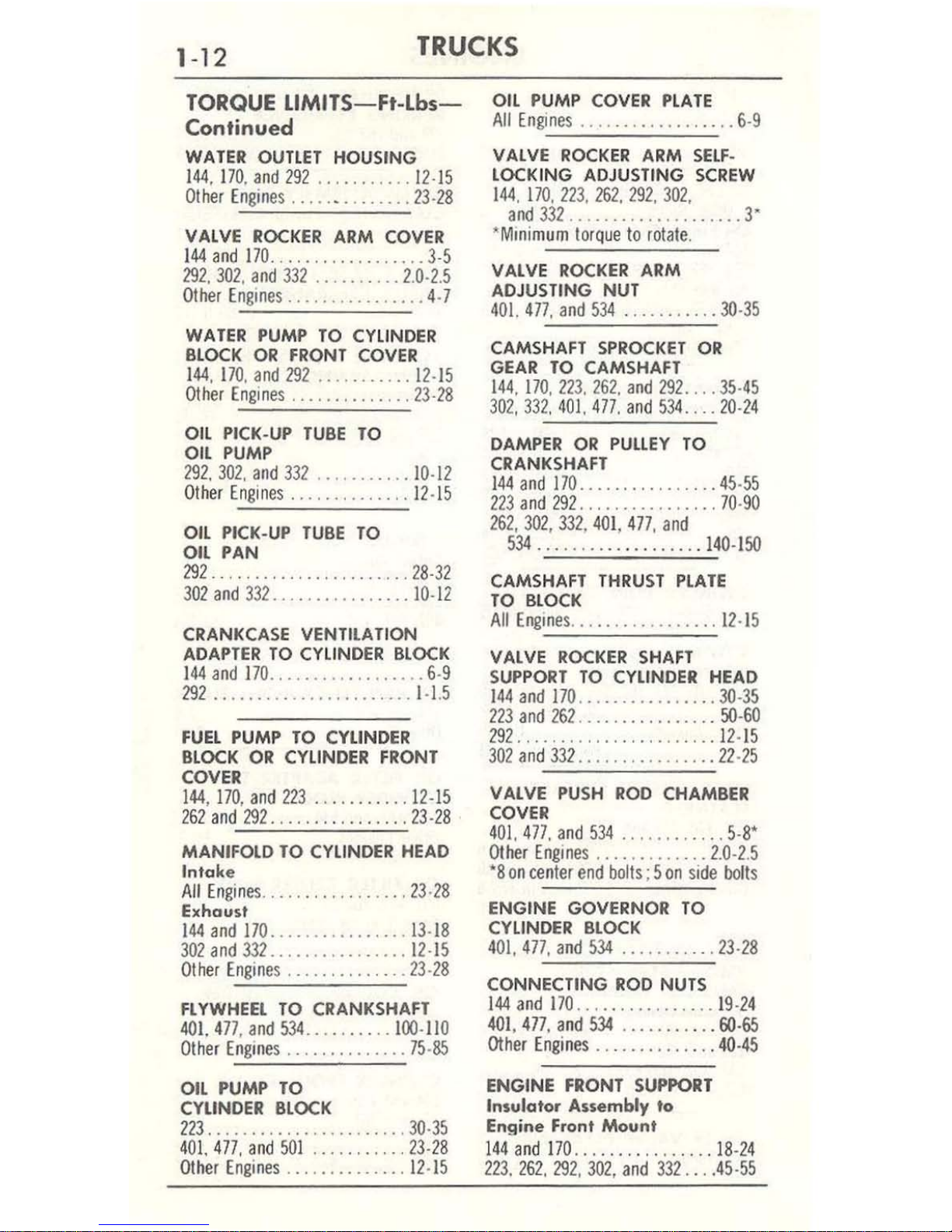
1-12
TRUCKS
TORQUE
LlMITS-Ft-Lbs-
Continued
WATER OUTlET HOUSING
144
, 170,
and
292
...........
12·15
Other
Engines .............. 23·
28
VALVE
ROCKER
ARM
COVER
144 and
170
..........
...
.....
3-5
292, 302, and
332
..........
2.0·2.5
Other
Engines
................
4-7
WATER
PUMP
TO
CYLINDER
BLOCK
OR
FRONT
COVER
144
, 170,
and
292
...........
12·15
Other Engines
.......
....
... 23-28
OIL
PICK-UP
TUBE
TO
OIL
PUMP
192,
302, and 332
...........
10·12
Other Engines
..............
12
-15
OIL PICK-UP
TUBE
TO
OIL PAN
292 .....
............
...... 28-
32
302
and
332
................
10·12
CRANKCASE VENTILATION
ADAPTER
TO
CYLINDER
BLOCK
144 and
170
..................
6·9
292
.......................
1-
1.5
FUEL
PUMP
TO
CYLINDER
BLOCK
OR
CYLINDER FRONT
COVER
144,170, and
223 ...........
12-15
262
and
291
.........
.......
23-28
MANIFOLD TO
CYLINDER
HEAD
Intake
A
ll
En
gines
.................
23·28
Exhaust
144
and
170
................
13·18
302
and
332..
..............
12-15
Other Engines
..............
23-28
FLYWHEEL
TO
CRANKSHAFT
401.
477
,
and
534
.....
.. .
..
100-110
Other
Engines
..............
75-85
OIL PUMP
TO
CYLINDER
BLOCK
223 .......................
30-35
401.
477, and
501
........... 23-
28
Other
Engines
..............
12-15
OIL PUMP
COVER
PLATE
All
Engines
................
, .6·9
VALVE
ROCKER
ARM
SELF
-
LOCKING ADJUSTING
SCREW
144, 170, 223,
262, 292
, 302,
and 332
....................
3"
~MlOi
mum
torque
to
rotate
.
VALVE
ROCKER
ARM
ADJUSTING NUT
401.
477, and
534 ...........
30-35
CAMSHAFT
SPROCKET
OR
GEAR
TO
CAMSHAFT
144,170,223,262,
and
292
.... 35-
45
302,332,
401.
477, and
534
.... 20-
24
DAMPER
OR
PULLEY
TO
CRANKSHAFT
144
and
170
......
...
....
... 45-
55
223
and
292 ..............
.. 70-
90
262,
302,
331, 401
,
477
,
and
534 .......
............
140·150
CAMSHAFT
THRUST
PLATE
TO
BLOCK
All
Engines
.................
12
·15
VALVE
ROCKER
SHAFT
SUPPORT
TO
CYLINDER HEAD
144
and
170
................
30-35
223
and
262
...............
. 50-
60
292 ......
..........
... ..
.. 12-
15
302
and
332
... , ............
22-25
VALVE
PUSH
ROD
CHAMBER
COVER
401.
477.
and
534
........
..
..
5·8'
Other
Engines
.............
2.0·2.5
'8
on
center
end
bolts
; 5
on
side
bolls
ENGINE GOVERNOR
TO
CYLINDER
BLOCK
401, 477, and
534
........
.. . 23-
28
CONNECTING
ROD
NUTS
144
and
170
................
19·
24
401, 477. and
534
......
.....
GO-
65
Other
Engines ......
.....
... 40-45
ENGINE FRONT
SUPPORT
Insulator Assembly to
Engine
Front
Mount
144
and 170
.........
....
...
18-24
223. 262, 292,
302, and
332
...
.45-55
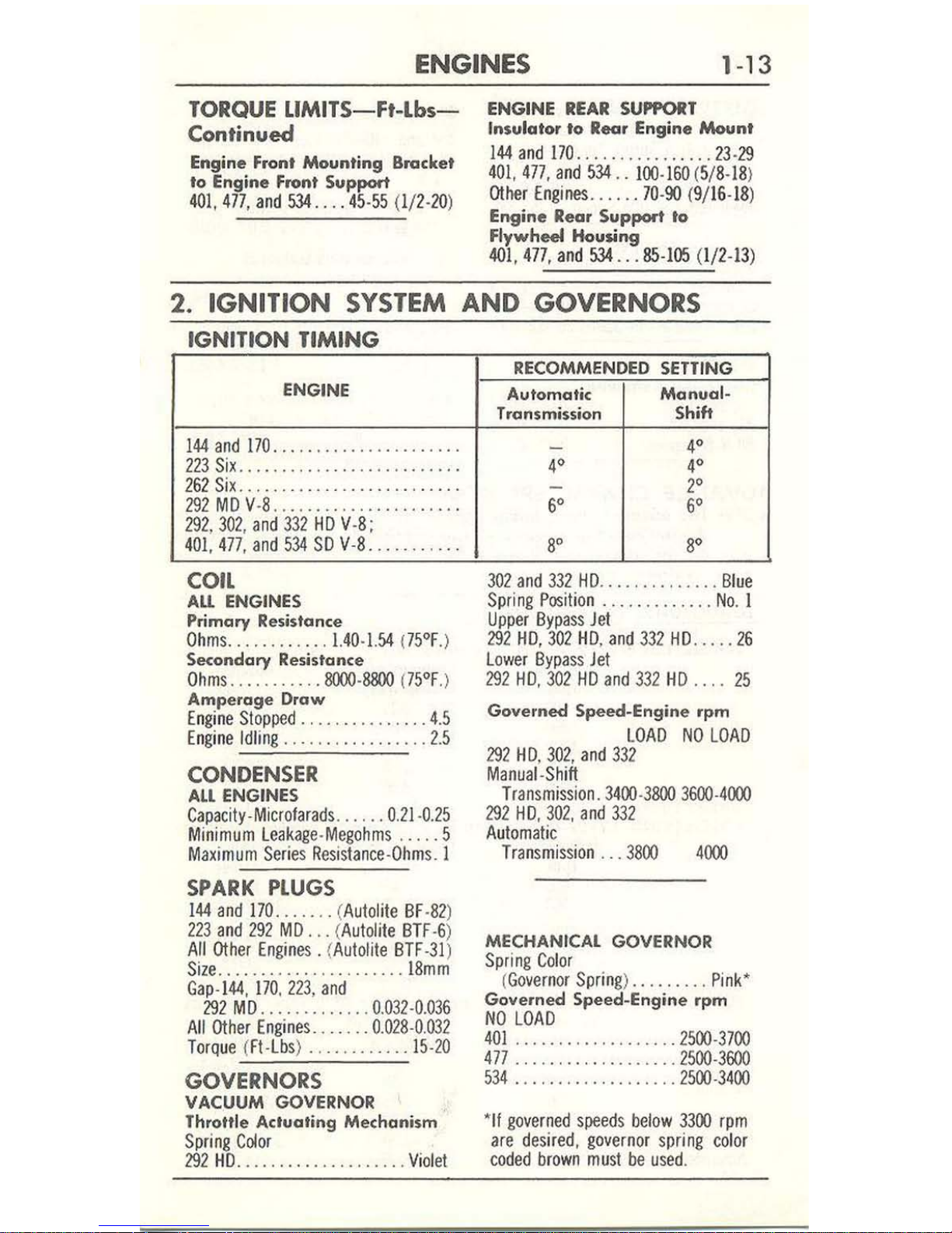
ENGINES
1-
13
TORQUE
LlMITS-Ft-lbs-
Continued
Engine Front
Mounting
Bracket
'0
Engine Front Support
401,
477,
and
534
....
45·55
(1/2·20)
ENGINE
REAR
SUPPORT
Insulator to Rear Engine
Moun.
144
and
170
................
23·29
401,477, and
534
.. 1
00·160
(5/
S·1S
)
Othfr
Engines
......
70·90 (9/
16·
1S)
Engine Rear Support to
Flywheel
Houfing
401,477,
and
534
...
85·1OS (1/2-13
)
2.
IGNITION
SYSTEM
AND GOVERNORS
IGNITION
TIMING
ENGINE
144
and
170
..... ,
., ......... , ....
223
Six ....
.....................
.
262
Six
......
.. .
................
.
292
MD
V·S
........
....
...
....
...
292,302, and
332
HD
V·S
;
401,477, and
534
SO
V·S ...
...
... ..
COil
AU
ENGINES
Primary
Resistance
Ohms
............ 1.40·1.54 U5°F
.)
Secondary
Resist
ance
Ohms
.. .
...
...
..
8000·8800 175°F
.)
Amperage
Draw
Engine
Sioppild
..........
..... 4
.5
Engine Idl
ing
..... .
...
...
.....
2.5
CONDENSER
All
ENGINES
Capacily·Microfarads
....
..
0.21·0.25
Minimum
leakage-Megohms
....
. 5
Maximum
Series
Resistance-Ohms
. 1
SPARK
PLUGS
144
and
170
....... (Autolite BF·S2)
223
and
292
MD
... (
Autolite
BTF
·6)
All
Other
Engines. (Autolite
BTF·31
)
Size ...
...
.. .. .
...
. ..
..... 18mm
Gap·I44, 170
, 223,
and
292
MD
.............
0.032 ·0.036
All
Other
Engines ......
. 0.
02S·0.03
2
Torq
ue (Ft·
Lbs
) .. ... .
....
.. 15·2
0
GOVERNORS
VACUUM
GOVERNOR
Throttle Actuating Mechanism
Spring
C~or
292
HD
...
...........
...
...
Violet
RECOMMENDE
D
SETTING
Automatic
Manual-
Transmission Shift
-
4°
4° 4°
-
2°
6°
6°
S'
so
302
and
332
HD
..............
Bl
ue
Spring
Position
.............
No
. 1
Upper
Bypass
Jet
292 HD,
302
HD,
and
332
HD .....
26
lower
Bypass Jet
292 HD, 3
02
HD
and
332
HD ....
25
Governed
Speed-Engine
rpm
LOAD
NO
LOAD
29
2 H
D,
302,
and
332
Manual·Shift
Transmission. 3400·3800
3600·4000
292
HD,
302,
and
332
Au
tomatic
Transmission
... 3800
4()(x)
MECHANICAL
GOVERNOR
Spring Col
or
(
Governor
Spring
) .
........
Pink
'
Governed Speed-Engine rpm
NO
LOAD
401
................... 2500·3700
477 ....
.........
......
2500·3600
534 ...
........
........
2500·3400
'If
governed
spileds below
3300
rpm
are
desired, governor
spring col
or
coded
brown
must
be
used
.

1-14
TR
UCKS
DISTRIBUTOR-General
All
SIX
CYLINDER
ENGINES
Br
eaker
Arm
Spri
ng
Tension-
GEAR
lOCATION
144 and
170-Dis
tan
ce Irom
bottom
of
gea
r to bottom of mounting
Ounc
es
........
..
......
..
17 ·20
rib
................
. 2.
510
-2.
515
Contact
Spacing .... ..
. .
0.024
·0.
026
223
and
262
- Distance
between base
Dwe
ll Angle
at Idl
e S
pee
d .. . 35° ·38°
a
nd
gear
..........
. .
0.005
-0.
008
All
V-8
ENGINES
Breaker
Arm Spr
ing T
ension
-
292-0
istance
froni bottom
of
mounti
ng flange
to
botto
m
Dunces ....
.... .
......... 17-2O
of
gear.
............
. 4.
991
-4.
996
Contact
Spaci
ng
...
.. ... 0.
014
-0.
016
Dwell
Angle at Idle Speed 26° -28·
1!2
° 3
02
and 332-Distance from
bott
om
of
mounting flange
to
bottom
SHAFT
END
PlAY
-
of
gear ..............
4.
927-4.953
Distributor Removed
144 and 170 .
.......... 0.022-0.033
401,477
, and 534- Distance
from
botto
m of mo
unt
ing lIan
ge
to
223
and
262 ........... 0.005
-0.
008
All
V-8 Engines
.....
... 0.022-0.030
bott
om of
gea
r .. .. .
.. 3.0
77 -3.
071
ADV
AN
CE
CHARACTERISTI
CS
NO
TE: The adv
ance
characteristics
giv
en
app
ly to the distributor
with
the indicated
numb
er
only. Th
e distributor number is st
amped
on
th
g distributor hous
;ng
or
on
a plate aHached to the
distributor housing.
LOADOMA
TIC
DISTR
tBU
TORS
144 S
ix
(C3UF-12127-E) Set
test sta
nd to:
1000 rpm, 0°, 0 i
nch
es
of
Mercu
ry.
Distr
ibu
tor
Vacuum-Inches
Advance-
r
pm
of
Mercury
Degree
s
500
0.30 1-2
800
O.
SO
4-3/4-5-3/4
1
200
L
SO
8~
1600
3.
00
10-11
2000
3.
90
11
-21-1/4
Ad
vance limi
t ...
...
...................
10.00
......
_ ..
13
-1/2
t
70 Six
(C3UF-12127 -D) Set
tes
t s
tand to:
1000 rpm, 0
°.
0 i
nches
of
Mercury.
Dis
tributor
Vacuum-Inches
A
dvance
-
rp
m
of Merc
ury
Degrees
600
0.
45
1/
4-1
-1/4
800
0
.75
3-
1/2-4-1/2
1
200
1.7
5 7 -8
1600
2.
90
9-3/4-
10-3
/4
2000
3.7
0
11-
12-1/4
Advan
ce limit
.........................
10.00
.........
..
.. ..
15
223
Six
(C3TF-12
127 -
D)
Set
test stan
d to: 150 rpm,
0°, 0 inches
of Mercu
ry.
Di
stribut
or Vacuum-Inch
es
Adva
nce·
r
pm
of
Mercury
Degrees
500
~
1
~~
600
0
.45
3-1/2-4
-1/1
1200
1.75
7-1/
2-8-1
/2
1
600
3
.10
9-10-
1/4
2000
4.
20
10-11-1
/4
Advance Limit
...
....
1000 .......
...
...
8.00 _ ..
... _ . _
....
14-3/4
..
,
•
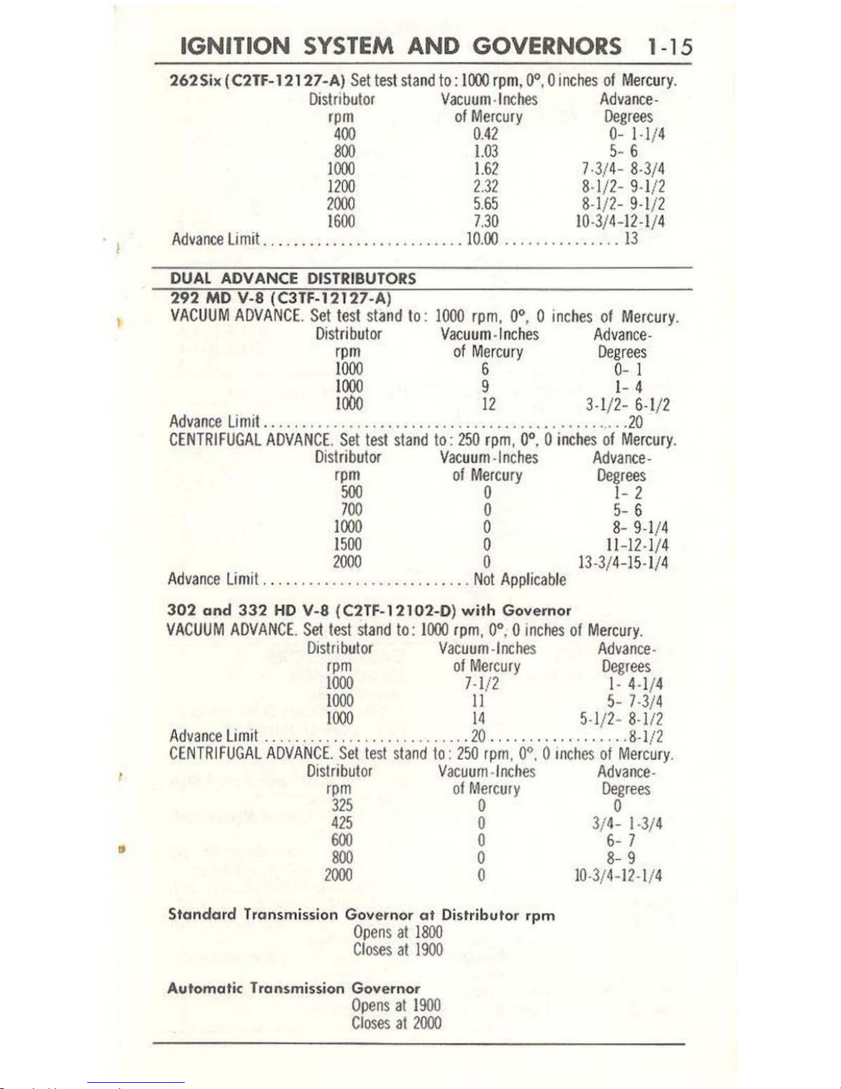
IGNITION
SYSTEM
AND GOVERNORS 1 -15
2625;
. (C2TF-12127-A) Settest
stand
to: 1000 rpm, 0', 0
inches
of
Mercury.
Distributor
Vacuum-Inches
Advance
-
rpm
of
Mercury
Degrees
400
0.42
0-
1·1/4
~
1m
~6
1000
1.62
)
·3/4-8·3
/4
1200
2.32
8·
1/2
- 9·1/2
2000
5.65
8·1
12-
9·1
/2
1600
).30
10
·3/4-
12·1
/4
Advance
limit. . .. ..
............
...
.
..10.00
...............
13
DUAL ADVANCE
DISTRIBUTORS
292
MD
V-8
(C3TF-12127-A)
VACUUM
ADVANCE. Set
test
stand to:
1000
rpm, 0'
, 0
inches
of
Mercury
.
Distributor
Vacuum-Inches
Advance·
rpm
of
Mercury
Degrees
1000
6 0- 1
1000
9 1
-4
1000
12
3·1/2-
6·1
/2
Advance
limit
.................................
....
.......
. '
..
20
CENTRfFUGAL
ADVAN
CE.
Set
test
stand
to:
250
rpm
, 0'. 0 inches
of
Mercury.
Distributor
Vacuum-Inches
Advance-
rpm
of
Mercury
Degrees
500
0
1-2
)00
0
5-6
1
000
0
8-9·1/4
1
500
0
11
-12
·1/4
2000
0
13
·3/
4-15
·1/4
Advance
limit
..............
...
..........
Not
Appficab
le
302
and
332
HD
V~8
(
C2TF-12102-0)
with
Governor
VACUUM
ADVANCE.
Set
test
stand
to: 1000
rpm
, 0'. 0
inches
of
Mercu
ry.
Distributor
Vacuum-Inches
Advance
-
rpm
of
Mercury
Degrees
1000
7·1
/2
I·
4·1/4
1000
II
5- )·3/4
1000
14
5·1/2- 8
·112
Advance
limit
...........................
20
.......
..
.........
8·1
/2
CENTRIFUGAL
ADVANCE. Set test s
tand to:
250
rpm
, 0
', 0 Inches
of
Mercury
.
Distributor
Vacuum-Inch
es
Advance
-
rpm
of
Mercury
Degrees
325
0 0
4
25
0 3/4-1
·3/
4
600
0
6-
)
~
0
~9
2
000
0
10
·3/4-12·1/4
Standard
Transm ission
Gov
ernor
at
Distributor
rpm
Opens
at
1~
Closes
at
1900
Automatic
Transmission
Gov
ernor
Opens
at 1900
Closes
at
2000
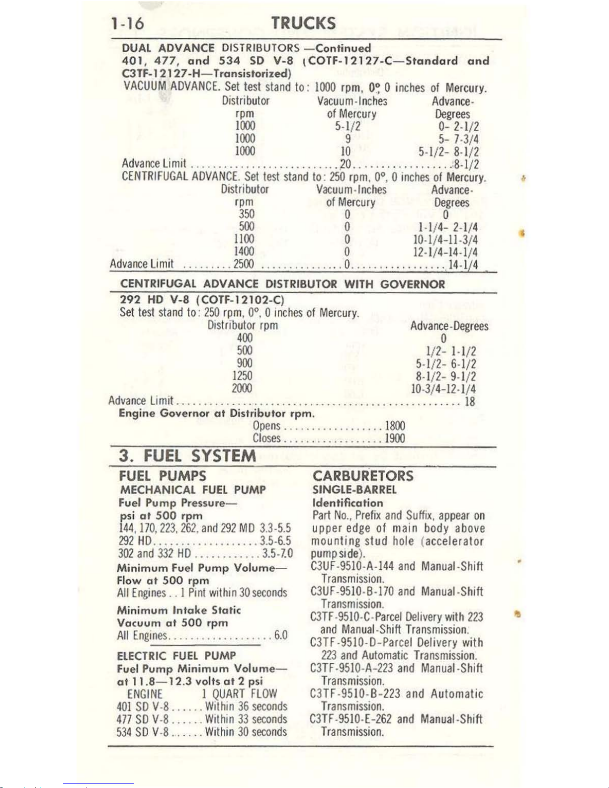
1-16
TRUCKS
DUAL
ADVANCE DIS
TRIBUTOR
S - Continued
401, 477,
and
534
SO
v-a
\COTF-12127-C-Stand
ard
and
C3TF.12127 -H- Transistorized)
VACUUM
ADVANCE.
Set
test stand to:
1000
rpm,
O~
0 inches
of
Mercury.
Distributor
Vacuum-Inche:;
Advance
-
rpm
of
Mercury
Degree
s
IIXX>
5·1
/2
0-
2·1/2
IIXX>
9
5-
7·3/4
I
IXX>
10 5·1/2-8·1
/2
Advance
Limit
..........
...
...
...
..... ,0
.....
...
...
. ,
....
. :8.1/2
CENTRIFUGAL
ADVANCE, Set
test
stand to:
250
rpm
, 0·, 0
inches
of
Mercury
.
Distributor
Vacuum-Inches
Advance·
rpm
of
Mercury
Degrees
350
0 0
500
0 1·1/4- 2·1/4
llOO
0
10
·1/4-11·3/4
1400
0
12
·1/
4-14
·1/4
Advance
Limit
...
, .. ,
2500
.... ,
....
. , 0
.......
.. "
......
.14.1
/4
CENTRIFUGAL ADVANCE
DISTRIBUTOR
WITH GOVERNOR
292
HD
v-a (COTF-12102-C)
Set test
sta
nd to:
150
rpm,
0·. 0 inches
of
Mercury
,
Distributor rpm
Advance-Degrees
400
0
500
1/1- 1·1
/2
900
5·1/2- 6·1/1
IB
8·~9·1
/2
1000
10
·3/4-12·1/4
Advance
Limit
.... , .............. , .... , ............
, .
......
, . ..
..
18
Engine
Gove
rnor
at
Distributor
rpm
.
Opens ...........
, . ,
...
. 1
800
Cl
oses
.....
, ,
..........
. 1
900
3_
FUEL
SYSTEM
FUEL
PUMPS
MECHANICAL FUel PUMP
Fuel Pump Pressure-
ps i
at
500
rpm
144,170,113,16
1.
and
292
MD 3.3·5.5
191
HD
........... , ....... 3.5·6.5
302
and 332
HD
.. ,
.........
3.5·7.0
Mi
nimum Fuel
Pump
Vol
ume
-
Flow
at
500
rpm
All
Engines .. I Pint
within
30
seconds
Minimum
Intake
Static
Vacuum
at
500
rpm
All
Engines ...........
..
....
, ,6.0
ELECTR
IC FUel
PUMP
fue
l Pump
Minim
um
Volume
-
at
11
.8-12.3
volts
at
2 psi
ENGINE
I
QUART
FLOW
401
SO
V·8
.,.,
.. Within
36 s
econd
s
477
SO
V·8, ,
....
Wit
hin
33 s
econds
534 SO
V·8 ...
...
Within
30
seconds
CARBURETORS
SINGLE-BARRel
Identification
Part No.,
Prefix
and
Suff
ix,
appear
on
upper
edge
of main body above
mounting
stud
hole (accel
erato
r
pu
mpside).
C3UF·
9510
·A·
144
and
Manual·Shift
Transmission.
C3UF·951O·B·170
and
Manual·Shift
Transmissio
n.
C3TF ·951O
·C·
Parc
el
Delive
ry with
123
and
Manual·Shift
Tra
nsmission.
C3
TF ·9510
·D-
Parcel Delivery
with
223 and
Automatic Transmissio
n.
C3TF ·9510·A-213
and
Manual·Shift
Tr
ansmissio
n.
C3TF·9510
-B-
213
and
Automatic
Tr
ansmissio
n.
C3TF·
951O·E-262
and
Manual·Shift
Tr
ansmissio
n.
•
•
FUEL
SYSTEM
1·17
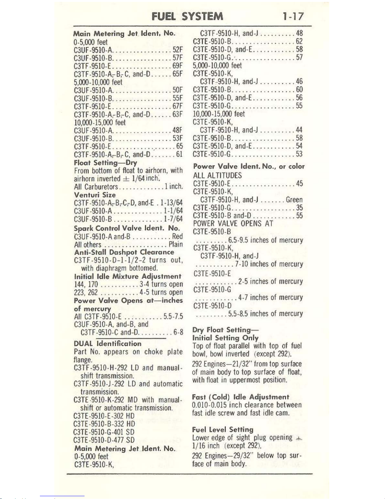
Main
Mete
ring Jet Ident. No.
0·5,000
feet
C3UF·951O
·A,
.......
..
.......
52F
C3UF·951O·B
.................
57F
C3TF
·951O·E
..........
....... 69F
C3TF
·951O·
A,
B,
C.
and
-D ..
....
65F
S,OOO ·10,000
feet
C3UF
·9510·A
...
.....
.........
50F
C3UF·951O
·B
.................
55
F
C3TF·951O·E.
................
67F
C3TF
·951O-A,B,C,
and·D
......
63F
10
,000·15.000
feet
C3UF·9510
·A
.................
48F
C3UF·9510
·B
.................
53F
C3TF
·951O·E
...........
'.'
.....
65
C3TF.951O·A,B,C, and·D
.......
61
Float
Setting-Dry
From
bottom
of
float
to
air
horn
,
with
airhorn
inverted
~
1/
64
inch:
All
Carburetors
.......
...... 1 inch
.
Venturi Size
C3TF·951O-AcB,C
,D,
anM
.
1·13/64
C3UF·95IO·A
..............
1·1/64
C3UF·951O
·B
..............
1·7/64
Spark Control Valve I
dent. No.
C3UF·951O·Aand,B
...........
Red
All
others
..................
Plain
Anti-Stall Dashpot Clearance
C3TF·9510·D-1·
1/2·2 tur
ns
out,
with
diaphra
gm
bottomed.
Initial Idle Mixture Adjustment
144, 170
...........
3·4
turns
open
223,
262
...........
4·5
turns
open
Power Valve
Opens
at-
inch
es
of mercury
All
C3TF·9510·E
...........
5.5·7
.5
C3UF·951O·A.
and
·B, a
nd
C3TF
·951O·C
and-D
..........
6·8
DUAL
Identificati
on
Part
No.
appears
on
choke
plate
flange.
C3TF·9510·H·292
LD
and
manual
·
sh
ift
transmission
.
C3TF·951O·J·292
LD
and
automatic
transmissio
n.
C3TE·951O
·K·
292
MD
with
manua
l·
sh
ift
or
automatic
transmission
.
C3TE·951O·E·3
02
HD
C3TE·951O·B·332
HD
C3TE
·951O·G-401
SD
C3TE·951O·D·477
SD
Main
Meter
ing Jet Ident, No.
0·5,000
leet
C3TE·951O·K
,
C3TF·9510·H, and
·J
..........
48
Cm
·951O·B
..................
62
C3TE·951O·D
, and·
E.
...........
58
cm
·951O·G.
' . .
...............
57
5,000·10,000
feet
C3TE
·951O·K,
C3TF
..
951O
·H,
and
·J
..........
46
C3TE·951O
·B ..................
60
C3TE·9510·D,
and
·E
.......
...
..
56
C3TE·951O·G
..................
55
10,000·15,000
feet
C3TE·951O·K,
C3TF·9510·H,
and-J
..........
44
C3TE·951O
·B
..................
58
C3TE·951O·D, and·E
............
54
C3TE·951O
·G ..................
53
Power
Valve
Ident. No.,
or
color
ALL
ALTITUDES
C3TE·9510
·E
..................
45
C3TE·951O
·K,
C3TF·951O·H
, and-J
.......
Green
C3TE·951O·G
..................
35
C3TE·951O
·B
and·D
.....
....
...
55
POWER
VALVE
OPENS
AT
C3TE·951O·B
·
........
6.5·9.5
inches
of
mercury
C3TE.951O·K
,
C3TF ·%IO·H,
and
-J
·
.........
.
7·10 inches
of
mercury
C3TE·951O
·E
·
..........
.
2-5
inches
of
mercury
C3TE·951O·G
·
..........
. 4-7
inches of
mercury
C3TE·9510·D
·
........
5.5·8.5 inches
of
mercu
ry
Dry F
lo
at
Setting
-
Initial Setting Only
Top
of
float
parallel
wit h top
of
fuel
bowl, bowl
inverted (except
292
).
292
Engines-21/32"
from
top
surface
of
main
body
to
top
surface
of
float,
with
float
in
uppermost
position.
Fast
(Cold) Idle Adjustment
0.010·0.015
inch
clearance
between
fast
idle
screw
and
fast
idle
cam.
Fuel
level
Setting
Lower
edge
of sight
plug
opening
"'-
1/
16
inch (except
292
).
292
Engines
-29/32"
below
top
sur·
face of main
body.
1-18
TRUCK
S
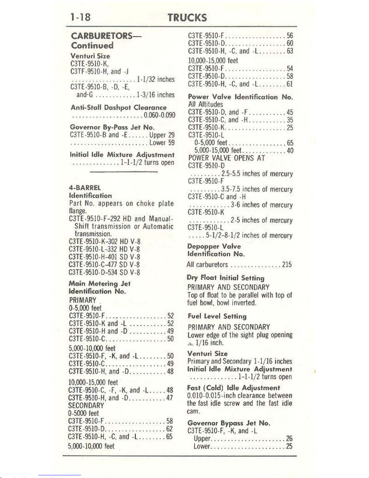
CARBURETORS-
Continued
Venturi Size
C3TE-951O-K,
C3TF-951O-
H, a
nd
-J
__
.................
1-1/32 inches
C3TE
-9510-B,
-0,
-E,
and
-G
___
..
_______
1-3/16
inch
es
Anti-Stall Dashpot Clearance
. . . _ .
____ . __
..
__
..
__ 0.060
-0.
090
Governor By-Pass Jet No.
C3TE-951O-
B a
nd -E.
_ .
... Upp
er
29
_________
..
__
...
____
... Lower 59
Initial Idle Mixture Adjustment
_ .
__________
. _
l-l
-l/
2 turns open
4-BARREl
Identification
Part N
o_
appe
ars
on c
hoke pla
te
nang
e_
C3TE-
9510-F-2
92
HD and
Manua
l-
Shi
ft transmis
sion or
Auto
matic
transmis
sion.
C3
TE-951O-K-302
HD
V
-8
C3TE-9510-L
-332
HD
V
-8
C3TE-9510-
H-4
01 SO V
-8
C3TE
-9510-C-477
SO
V
-8
C3TE-9510-D
-53
4 SO V-8
Main
Metering Jet
Identification No.
PRIMAR
Y .
0-
5,000
feet
C3TE-
951O
-F
__ __
_______
..
__ . __
52
C3TE-951O-K
and
-L ____
____ . __
52
C3
TE-
951O
-H and
-0
___________
49
C3TE-951O
-C
____
... ____
_______
50
5,
000-10,000
feet
C3TE-
951O
-F, -
K,
and
-L. _
__ . ___ 50
C3TE-951O
-C
__________
.. . _____
49
C3TE-951O
-H,
and
-0 ____ .
______
48
10,000-15
,000
feet
C3TE-9510
-C, -F, -K,
and
-L
___
__
48
C3TE-
951O
-H,
and
-0
________ . __
47
SECONDARY
0-
5000
feet
C3TE-951O
-F
__________________
58
C3TE-951O-D _
____
. _.
__________ 62
C3TE-
951O
-H, -C, a
nd
-
L.
______
_
65
5,
000-10,000
feet
C3TE-951O-F
_____ . __________
56
C3TE-951O-D_
. _ . _ ..
__
...
_ ..
___
60
C3TE-951O-H, -C_ and -
L.. ______
63
10
,000-15,000 feet
Cm-951O
-F
______
...
_______
54
C3TE-951O-D ________
.......
.. _
58
C3TE-
951O
-H,
-C, and
-L
__
...
___
61
Power
Valve
Identification No.
All
Alt
iludes
C3TE-951O
-D,
and -F
___
_ .
______
45
C3TE-951O-C
, and -H
__
. __
______
35
C3TE-9
51O
-K .. . ..
___ . __ . ______
25
C3TE-951O-
L
0-5
,000 fee
f..
_____
...
_______ 65
5,
000-15,
000 feet.
..
_________ . 40
POWER
VALVE
OPENS AT
C3TE-9510-
D
· . .
______ 2_5-5_5 inch
es
of
mercury
C3TE-951O-
F
_________
3.5-7.5
inches
of
mercu
ry
C3TE-9510-C
and
-H
·
...........
3·6 inches
of mercur
y
C3TE-951O-K
.. .
.....
....
2-5 inc
hes
of mercury
C
3TE
-951O-
L
·
____ 5-1/2- 8-1
/1 inches
of
mercur
y
Oepopper Valve
Identification
No.
All carburetors
_________ . _____
215
Dry Float in itial Setting
PRIMARY
AND
SECONDARY
Top
of
float to
be parallel with
top
of
fu
el
bowl
, bowl inverted
.
Fuel Level Setting
PRIMARY AND
SECONDARY
Lower
edge of the sig
ht
plug
opening
_"'-
1/ 16 inch_
Ventur
i Size
Primary and
Secondary 1-1/
16
inches
Initial Idle
Mixture Adjustment
______
...
_____
1-1-1/2
turns
ope
n
Fast (Cold) Idle Adj
ustment
0_OIO-0_OI5-i
nch
cle
arance
between
the fast idle
screw and the
fast idle
cam
.
Governor
Bypass
Jet No.
C3TE-951O-F, -K,
and
-L
Upper.
______
..
_____________
26
Lower
_______ . ______
________
25
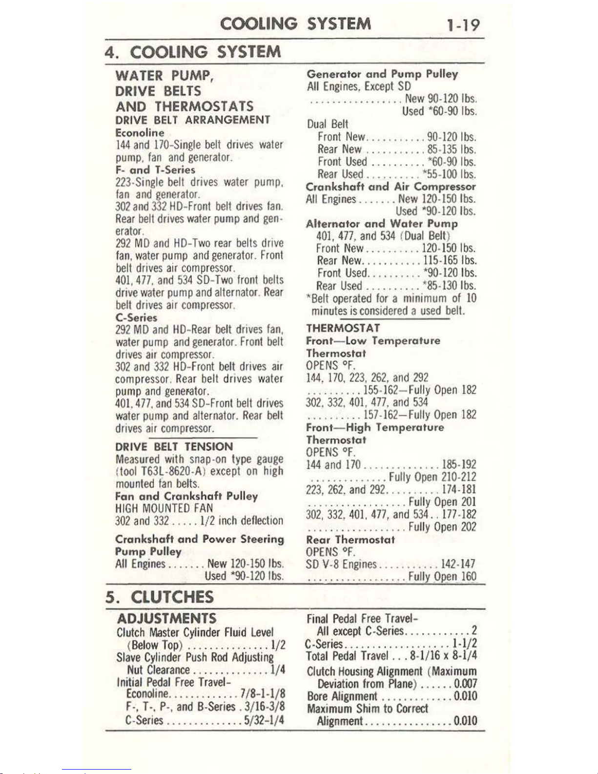
COOLING
SYSTEM
1-19
4. COOLING
SYSTEM
WATER
PUMP,
DRIVE
BELTS
AND
THERMOSTATS
DRIVE
BELT
ARRANGEMENT
Econoline
144
and
170-Sin
gle
belt dri
ves
waler
pump, fan
and
generator.
F-
and T-Se
ries
223·Single
belt
drives
water
pump,
fan
and
gene
rat
or.
302 and
332
HO-Front
belt
drives
Ian
.
Rear
belt
drives
water
pump
and
gen-
erator
.
292
MO
and
HO-Two rear
belts
drive
fan,
water
pump
and
generator.
Fro
nt
belt
drives air
com
pressor.
401.
477.
and
534 SO-
Two
lro
nt
bells
drive
water
pump
and
alternator.
Rear
belt
drives
air
compressor
.
C-Series
292
MO
and HO-
Rear
belt
drives
lan,
water
pump
and
generator.
Front
belt
drives
air
compressor.
302
and
332 HO-Front
belt
drives
air
compressor
. Rear b
ell
drives water
pump
and
genefator.
401. 477.
and
534
SO-Fro
nl
belt
drives
water
pump
and
alternator.
Rear
bell
drives
air
compressor.
DRIVE
BELT
TENSION
Measured
with
snap-on type
gauge
(
tool T63l ·
8620
·A)
except
on
high
mounted
fan
belts.
Fan and Crankshaft Pulley
H
IGH
MOUNTED
FAN
302
and
332
..... 1/2
inch
deflection
Crankshaft
and
Power Steering
Pump Pulley
All
Engines
.......
New
120·150
Ibs
.
Used
"90·120
Ibs
.
5.
CLUTCHES
ADJUSTMENTS
Clutch
Master
Cylinder
Fluid
level
(
Below Top) ...............
1/2
Slave
Cylinder Push
Rod
Adjusting
Nut
Clearance
.............
. 1/4
Initial Pedal Free
Travel
-
Econoline .............
7/8-1·1/8
F
·,
T·, p',
and B·Series
. 3/16·3/8
C·Series
.......
....... 5/32-1
/4
Generator
and
Pump Pulley
A
ll
Engines.
Except
SO
.............
....
New
90·120
Ibs.
U
sed
"60·90
Ibs.
Dual
Belt
Fro
nl
New
...........
90·120
Ibs.
Rear
New
...........
85·135
Ibs
.
Front
Used
...
...
....
'60·90
Ibs.
Rear
Used
..........
"55·100
Ibs.
Crankshaft
and
Air Compressor
All
Engines ... , ...
New
120·150
Ibs.
Used
"90·120 Ibs.
Alternator
and
Water Pump
401,477, and
534
(Oual
Belt
)
Fr
ont
New ..........
120·150 Ibs.
R
ear
New
.........
..
115·165Ibs.
Front Used
........
..
"90·120 Ibs.
Rear
Used
.......... '85·130
Ibs.
'Belt
operated
for a mini
mum
of
10
minutes
is
considered a used
bell.
THERMOSTAT
Front- Low T
empe
rature
Thermostat
OPENS OF.
]014, 170,
223,
262,
and
292
.........
.
155·162-Fully
Open
182
302. 332,
401.
477, and
534
.
.......
..
157·162-Fully
Open
182
Front- High
Temp
erature
Thermostat
OPENS
OF.
t44
and
170
..............
185·192
.
.....
........
Fully
Open
210·212
223,262.
and
292 ..........
174·181
....
..........
.... Fully
Open 201
302,331
.401.
477, and
534
..
177·182
..................
Fully
Open
202
Rear
Thermostat
OPENS OF.
SO
V·8
Engines
...........
142·147
.
.................
Fully.Open
160
Final
Ped
al
Free
Travel-
All
except C·Series
............
2
C
·Se
ries ......
...
.......... 1.1/2
Total
Pedal
Trav
el
...
8·1116 x 8·
1/4
Clutch Hous
IOg
Alignment (Maximu
m
Devia
tion
from
Plane) ...... 0.007
Bore
Nignment , ..........
..
0.010
Maximum
Shim
to
Correct
Nignment.
...............
0.
010

1-20
TR
UCKS
TORQUE LlMITS-FI-Lbs
Pressure Pla
te
to
Flywh
eel Bolt
..... 20·25
(5/16·18
)
25·30
(3/8·16)
Clutch
Hous
ing
to
Engine
Block
Bolt
....... 40·
45
(7/16·14)
Clutch
Slave
Cylinde
r to
Clutch
Housing
Bolt
..... 30·3
8 (7/16·14)
6_
MANUAL-SHIFT
TRANSMISSIONS
TORQUE LlMITS-FI-Lbs
Reve
rse
lockout
Plung
er
Retainer
Bolt ...
....... 80·100 (11/16-16
)
Flywheel
Housing
to
Engine Bloc
k
Bott
............
41)·50
0/16·14)
Insulator
to
Tran
s.
Assy. Front & Rear
Bolt & Nut (Aux.
Tran
s.
only
)
.............. 195·235
(3/4.16)
Output
Shaft
Bearing Retainer
to
Trans. Case
Bott
...
20·25
(3/8·16
)
30·38 (7/16·14)
50·62 (1/
2·13
)
96·120
(5/
8·11
)
Gear
Shi
ft
lever Tower
to
Gearshift
Housing
Bolt.
.....
20·25
(3/8·16
)
30·35
(7/16·t4)
Clutch
Housing
to
Tran
s.
Case
Bolt
.
.............
.
30·38
(7/16·14)
96-120
(5/
8·11
)
70·90
(9/16·12)
Clutch Hous
ing
to
Trans.
Case Nut
...............
35·45
(7/
16·20
)
11
5·141)
(5/
8·18
)
81·102
(9/16·18
)
Rear
Mounting
Bra
cket
to
Aux.
Trans.
Bolt
...
.........
41)·45 (7/l
6·14
)
Rear Sup
port Plate
to T
rans. Aux.
Case
Nut ....... 115·
140
(5/
8·18
)
Brake
Support
Plate
to Tran
smiss
ion
S
upport
Plate
Bolt & Nut
........
........
58·72 (1/2
·20)
U-Joi
nt Flan
ge
to
Transmission
Out
-
put
Shaft
Nut
... 90·12
5 (
1.00·20
)
275·350
(1·
1/2·18)
225·275 (1.1/4.18)
Input
Shaft
Yoke
to Aux.
Tran
s.
Nut
.............
275·350
(1·1/4.
18)
Bracket (Aux
.)
Trans.
Control to
No.3
Cross
member
Bott & Nut
................
24·30 (3/8.24
)
S
upport
Trans
. (
Rear) to
Frame Sid
e
rails
Bott
or
Nut (8·Speed
Trans
·
mission only)
....
41)·55
(7/16·20)
Insulator
to
Trans. Rear
Support
Stud
&
Nut (8·Speed Trans. only
)
.
.............
.
90·110
(3/4.16)
Trans. Rear Mount
Plate
to Insu
lator
Stud&
Trans. Support
Nut (8·Speed
Trans. only) .... 195·235
(3/4·16
)
Parking
Brake
to
Transmission
Sea
r-
ing
Retainer
Bolt.
180·
220
(5/8·18)
50· 70 (7/16·20)
24·30
(3/8·24)
45·55
(1/2
·20
)
Drum
Parking
Brake
to
Companion
Flange
Nut
.....
..
35·45
(3/8-24)
50·70
0/1 6·20)
75-80
(1/
2·20
)
Bellcrank to Tra
nsmiss
ion
Nut
.............
..
70·90
(9/16·18)
L
eve
r
Assy
.
to
Transmissi
on
Bolt
...........
...
..
20·25
(3/8·16)
Support
to
Transmission
80lt
....
.. ..
...
.....
20·25
(3/
8·16
)
8ellcra
nk Mounting
Bracket
to
Cross
·
member
Bolt
& Nut 20·
25 (3/8·1
6)
24·30 (3/
8·24
)
8ellcrank
to Mount
ing
Bracket
Bolt
&
Nut
..........
100-120
(9/16·18
)
Handbrake
Anchor
Bar
to
Tran
s.
Case
Nut (exce
pt 5·S
peed
Extra
·He
avy
Duty) ......
...
100·110
(9/16·18)
Handbrake
Anchor
Bar
to Trans.
Case
Nut
(5·
Speed
Extra·Heavy
Duty
on
ly)
......... 120·130
(9/16-18)
8ellcrank
to
Trans. Bolt
. .
..............
20·25
(3/8·16)
Reverse Lockout
Plunger
Retainer
Bolt
......
.... 80·
100 (11/16·16
)
Countershaft
Rear
Bearing
Retainer
Bolt ..........
..
25·30
(5/16·18)
35-40
(3/
8·16
)
45·55
(7/
16·14
)
60-70
(l/
2-13
)
Converter
Housing
to
Flywheel
Hous
·
ing Bolt
........
..
20·25
(3/8.16)
Flywheel
Housing
to Engine
Btock
Bolt
......
. .. ...
40·50
(7/16·14)
Rear
Cross
Shaft
Housing
to
Adapter
or
Trans. Assy.
Bolt
.......
........
30·38
(7/16·14)
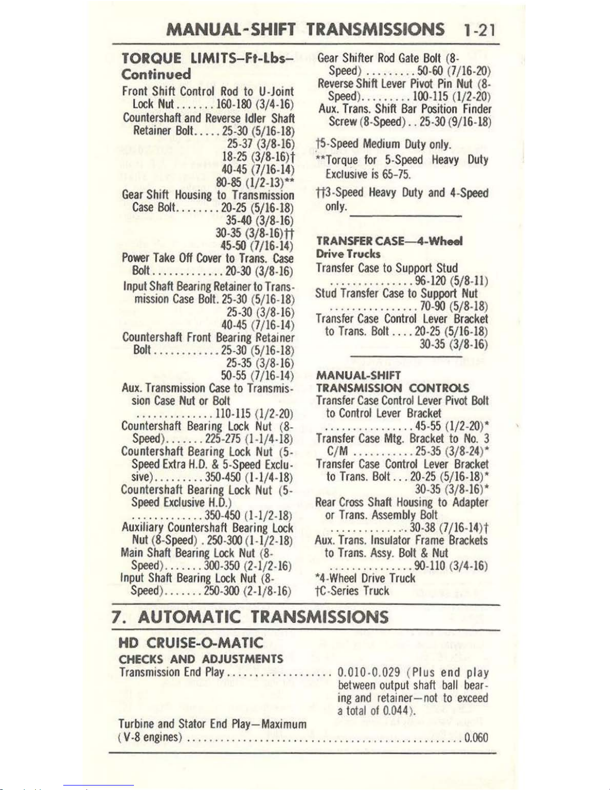
MANUAL-SHIFT
TRANSMISSIONS
1-
21
TORQUE lIMITS- Ft-
Lbs-
Continued
Front
Shift
Cont
rol
Rod
to
U·J
oint
L
ock
Nut
....
. , .
160·I&:l
(3/4·16)
Countershaft
and
Reverse Idl
er
Shaft
Retainer
BoIt. ....
2S·3O
(S/16·18)
2S·37
(3/
8·16
)
18·15 (3/8·16H
4O·4S (7/16-14)
&:l·85
(1/2-13)""
Gear
Shift Housi
ng
to
Transmissio
n
Case
BoIt.
.......
20·15 (S/16·18
)
3S-40
(3/8.16)
30·35
(3/8-16m
4S·50
(7/16·14
)
Po
wer Take Off
Cover
to Trans.
Case
Bolt.
............
20-30
(3/
8·16)
I
nput
Shaft
Bearing
Retainer
to
Trans·
mi
ssion
Case Bol
t.
25·30
(5/16·18)
25·30
(3/8·16)
40·45 (7/16·14)
Countershaft
Front
Beari
ng
Retainer
Bolt
............
25·30
(5/16·18)
2S·35
(3/8·16)
50·55
(7/16·14)
Aux
. Tran
smission
Case
to
Transmis
-
sion
Case
Nut
or
Bolt
....
........
..
1l0·115
(1/
2·20
)
Countershaft
Beari
ng
Lock
Nut (8·
Speed) .......
225-275
(1.
1/4·18)
Countershaft
Bearing
Lock
Nut
(S·
Speed
Extra
H.O. &
5·Speed
Exclu
·
sive) .
........
350·450
(1.1/4·18)
Countershaft
Bearing
Lock
Nut
(5·
Speed
Exclusive
H.D
.)
..
, .,
... , ....
350·450
(1·1/2.18)
Au
xiliary Coun
tershaft
Beari
ng
Lock
Nut
(8·
Speed) .150·300
(1·
1/2·18)
Main Shaft
Bearing
Lock
Nut (8·
Speed) .. , ....
300·350
(2·1/2·16)
Inp
ut Sh
aft
Beari
ng L
ock Nut
(8·
Speed
). , .....
250·300
(2·1/8.16)
Gear Shi
fte
r R
od Gate
Bol
t (8·
Speed
) . .. , . , .
.. 50·
60
(7/16·20)
Reverse
Shift
Lever
Pivot
Pin
Nut (8.
Speed) .........
100·115 (1/2-20)
Aux. Trans.
Shi
ft Bar Position Finder
Screw (8·S
peed
) .. 25·
30
(9/16·18)
j5·Speed
Medium
Duty
only
.
""
Torque
for 5·Speed
Heavy Duty
EXClusive
is
65-75
.
ttl
·S
peed Heavy
Duty
and 4-S
peed
only.
-----
TRANSfER
CASE-4-Wh
.....
Drive Trucks
Transfer Case
to Support Stud
. . .
........
.... 96·
120
(5/
8·1l
)
Stud
Transfer
Case
to
Support
Nut
..... , ...... , ... 70·
90
(5/8.18)
Transfer
Case Conlr
ol
Lever Bracket
to
Trans.
Bolt., ,
.20·25
(S/1
6·18
)
30·35
(3/
8·16
)
MANUAL-SHIFT
TRANSMISSION CONTROLS
Transfer
Case
Control
Lever Pivot
Bolt
to
Control
Lever
Brocket
...
..........
, , . 4S·
55
(1/2-20
)"
Transfer Case
Mtg. Bracket
to No, 3
C/M .
.......... 25·35
(3/8·24)"
Transfer
Case Con
trol
Lever
Bracke
t
to T
rans. Bolt
... 20·
25
(5/ 16·18)"
30·35
(3/
8·1S)"
Rear
Cross
Shaft Hou
sing
to
Adapter
or
Trans. Assemb
ly
Bolt
.
...
.. , ...
, .... 30·38
(7/16-14)t
Aux. Trans. Insulator
Frame
Brackets
to
Trans. Assy. Bolt & Nut
...... , ........
9O-1l0
(3/4·16)
"4·
Wheel Drive Truck
tc·
Series
Truck
7.
AUTOMATIC
TRANSMISSIONS
HD CRUISE-O-MATIC
CHECKS AND ADJUSTMENTS
Transmission
End
Play
................
...
0.010·0.
029 (Plus end
play
between
output
shaft
ball
bear
·
ing
and
retainer-not
to
exceed
a
tot
al
ot
0.044
).
Tu
rbine
and
Stator
End
Play-Maximum
(
V·8
engines) ..
.................
.. ,
.... , ...... , ...............
0.060
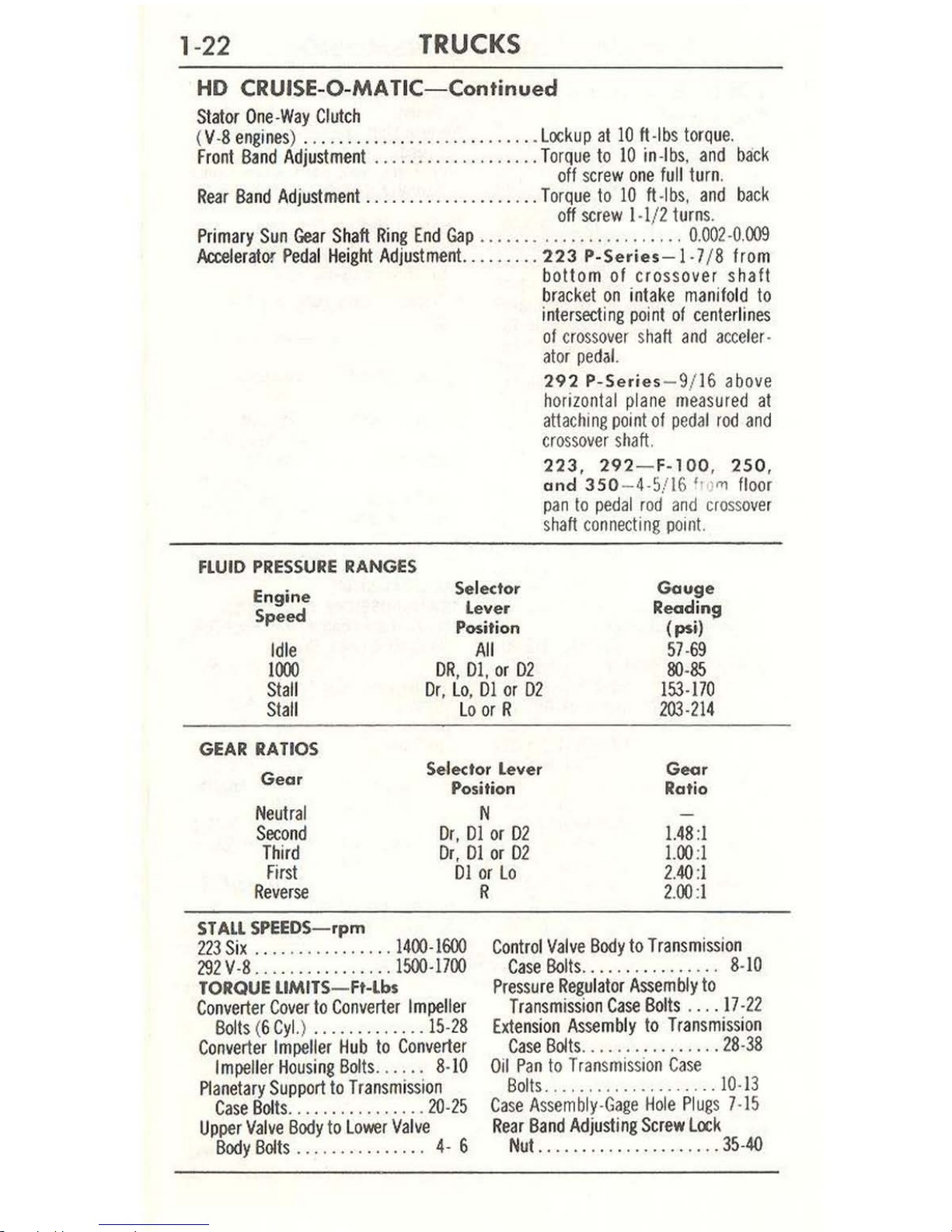
1-22
TRUCKS
HO
CRUISE
-O-
MA
TIC-Continued
Stator
One·Way
Clutch
(V
·8
engines) ..............
.............
Lockup
at
10
ft
·Ibs
torque.
Front
Band
Adjustment
.....•...•...•.....
Torque
to
10
in·lbs.
and
back
off
screw
one
full
turn
.
Rear
8and
Adjustment
....................
Torque
10
10
ft·lbs.
and
back
off
screw
1·1/ 2
turns
.
Primary
Sun
Gear Shaft
Ring
End
Gap
.................
...
... 0.002 ·0.
009
ActeIerator
Pedal
Height
Adjustment
.........
223 P-Se<ies- l ·7/ 8
from
bottom of crossover shaft
bracket
on
intake
manifold
to
intersecting
point
of
centerlines
of
crossover shaft
and
acce
ler·
ator pe
dal.
FLUID
PRESSURE
RANGES
292
P-Series
- 9/16 above
horizontal
plane
measured
at
attaching
point
of
pedal
rod
and
cro
ssover shaft.
223, 292- F-100, 250 ,
and
350
- 4-5/16 '
l'i
l'l1
floor
pan
to
pedal rod
and
cross
ove
r
shaft
connecting
point.
Engine
Speed
Selector
Gouge
Readi
ng
(psi)
57·69
80·85
153·170
203·214
Lever
Position
All
Idle
lin)
Stall
Stall
DR, Dl
, or
02
Or, Lo,
01
or
02
Lo
or
R
GEAR
RATIOS
Gear
Selector
Lever
Position
Goor
Rat
io
N
Neutral
Second
Third
First
Dr,
Dl
or
D2
Dr, Dl
or
02
Dl
or
Lo
1.48
:1
1.00
:1
2.40:
1
2
.00:
1
Reverse
STAll SPEEDS-rpm
223
Six
....
........
....
1400·1600
292V
·8
................
1500·1700
TORQUE
LlMITS-Ft-
lbs
Converter
Cover
to
Converter Impeller
Bolts
(6
Cyl.) .............
15·28
Converter
Impeller
Hub
to
Converter
Impell
er
Housing
80Its ....
..
8·10
Planetary
Support
to
Transmission
Case
801ts ..........
......
20·25
Upper
Valve
Body
to
Lower
Valve
Body
Bolts
..
. . .. ..
.. ..
...
4· 6
R
Control
Valve
Body
to
Transmission
Case
Bolts..
.. . .
.. ..
. ..
... 8·10
Pressure
Regulator
Assembly
to
Transmission
Case
Bol
ts .... 17·
22
Extension
Assembly
to
Transmission
Case
Bolts
......
..........
28
·38
Oil
Pan
to
Transmission
Case
Bolls
................
.... 10·
13
C
ase Assembly·Gage Hole
Plug
s 7·15
Rear
Band
Adjusting
Screw
Lock
Nut.
................
....
35·40
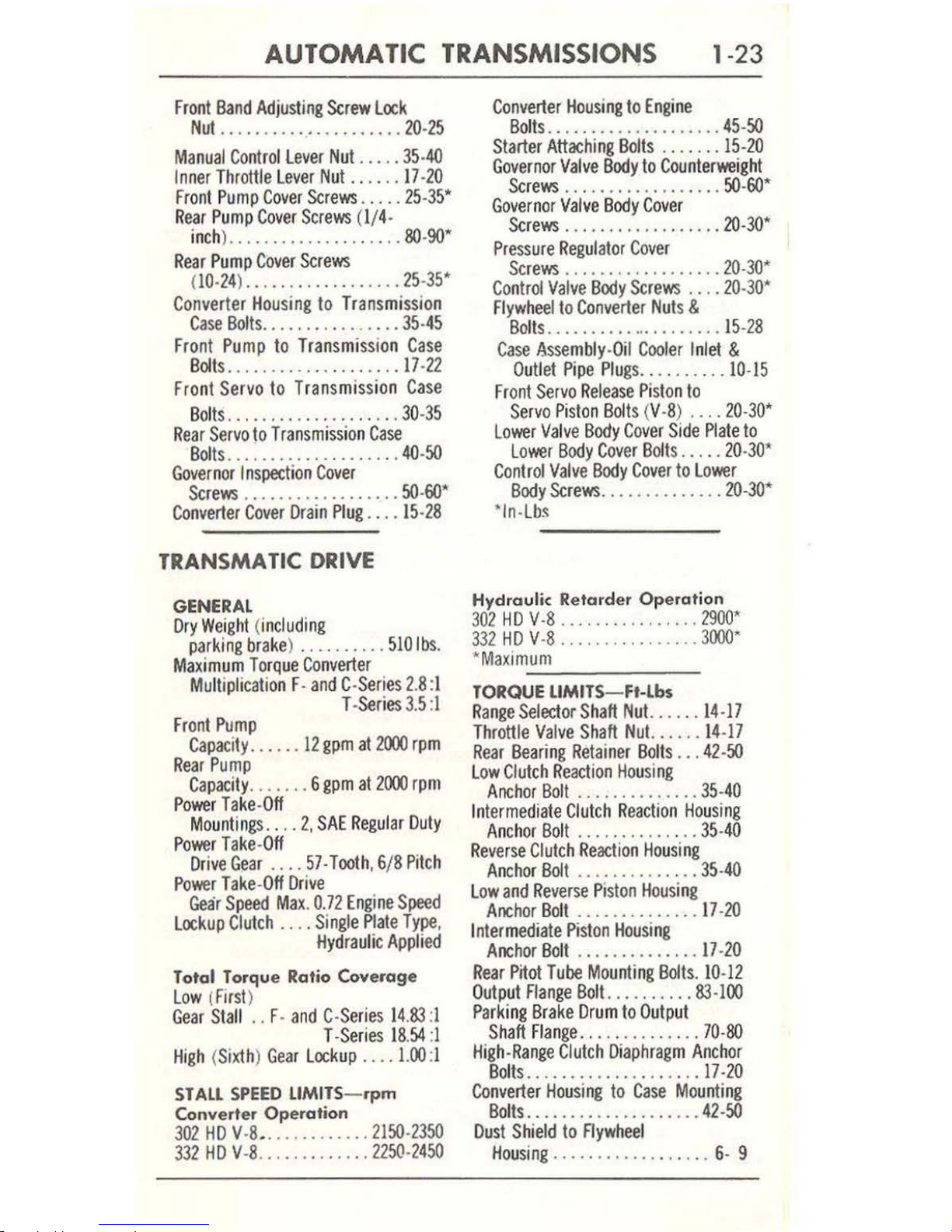
AUTOMATIC
TRANSMISSIONS
1-23
Front
Band
Adjusting
Screw
Lock
Nut
.....................
20-25
Manual
Cont
rol
Lever
Nut .....
35·4{)
Inner
Throttle Lever
Nut
....
.. 17 -
20
F
ront
Pump
Cover
Screws ..... 25-35'
Rear
Pump
Cover
Screws (1/4-
inch) ...............
.
.... 80-
90'
Rear
Pump
Cover Screws
(10-24) ...........
.
...... 25-3
5'
Converter Housing
to Transmission
Case
Bolts
................ 35·
45
Fro
nt
Pump
to
Transmi
ssion Case
Bolts ............
.
.......
17·22
Front Servo
to Transmission
Case
Bol
ts
...........
.....
.... 30-
35
R
ear Ser
vo
to
Transmission
Case
Bolts
....................
4{)-5O
Governor
I n
spection
Cove
r
Screws ..................
50·60'"
Converter
Cover
Drain
Plug
.... 15·
2S
TRANSMATIC DRIVE
GENERAL
Dr
y Weig
ht (including
parking
brake) ..........
5101b
s.
Maximum
Torque Convert
er
Multiplication F-and C-Series 2.S:
1
T -
Series 3.5
:1
Front
PtJmp
Capacity ....
..
12
gpm
at
2000
rpm
Rear
Pump
Capacity
....... 6 gpm
at
2000 rpm
Power
Take-Off
Mo
untings
.. ..
2,
SAE Regu
lar Duty
Power Take-Off
Drive Gear
.... 57·
Tooth
, 6/S Pitch
P
ower Take-Off
Drive
Gear Speed
Max
. 0.
72
Engine
Speed
L
ockup
Clutch
....
Single
Plate
Type
,
Hydrau
lic
Applied
Totol Torqu e Ratio Coverage
Low (Firs
t)
Gear Stall
..
F·
and C-Series 14.83
:1
T
-Series IS.54:1
Hi
gh
(Si
xth) Gea
r L
ock
up
....
1.00
:1
STALL
SPEED
LlMITS-
.pm
Conv
erter Oper
ation
302
HD V·S_ ............ 2150
-23
50
3
32
HD V-S
.... , ........ 2250-2450
Conve
rter Housing
to
Engine
Bolts
...................
.45-50
Starter Attaching
Bolts
.....
.. 15-
20
Governor
Valve
Body
to Counterweight
Screws
................
.. 50-
GO'
Gove
rnor Valve
Body
Cove
r
Sc
rews .............
.....
20-30'
Pressure
Regulator
Cove
r
Screws
.................
. 20-3
0'
Co
ntrol
Valve
Body
Screws
.... 20-3
0'
F
lywheel
to
Converter
Nuts
&
Bolts
.....................
15-2S
Case
Asse
mbly-Oil
Cooler Inlet
&
Outlet
Pipe Plugs ..........
10·15
Fr
ont
Servo Release
Piston
to
Servo
Piston
Bolts
(V ·S)
....
20·30'
Lower Valve
Body
Cover
Side Pla
te to
Lower
Body
Cover
Bolts ...
.. 20-30'
Control
Valve
Body
Cover
to Lower
Body
Screws
..............
20-30
'
'
In·Lb
,
Hydraulic
Retarder Ope
ration
3
02
HD
V-S
.......... ' .'
...
2900'
332
HD V-S
................
3
000'
"'
Maximum
=:...----
TORQUE
LIMITS-F.-lb.
Ran
ge Selector Shaft
Nut
......
14-17
Throttle
Valve
Shaft
Nut.
.....
14-
17
Rear
Bearing
Retainer
Bolts
... 42-
50
L
ow
Clutch Reaction Hou
sing
Anch
or
Bolt
............
.. 35-
40
In
termediate
Clutch
Reaction
Housing
Anchor
Bolt
...........
.
.. 35·40
Rev
erse
Clutch
Reaction Hou
sing
Anchor
Bolt
..............
35·4{)
l
ow and
Reverse
Piston
Housing
Anchor Bolt
..............
17-20
I
ntermediate
Piston Housing
Anchor
Bolt .........
, .
...
17-20
R
ear Pnot
Tube Mounting Bolts. 10-12
Output
Flange
Bolt.
......... 83-100
Parki
ng
Brake
Drum
to Output
Shaft Flange ..............
70-80
High-Range
Clutch
Diaphragm
Anchor
Bolts ...................
. 17·
20
Converter
Housing
to
Case Moun
ting
Bolts ....................
42-50
Dust Shield
to
Flywhee
l
Hou
sing
............
.
.....
6- 9

1-24
TRUCKS
TRANSMATIC
DRIVE-
Continued
Converter
Pump
Cover
Nuts
... 19·23
Hydraulic Retarder
Control
Valve
Body
80lts
...............
15-18
Oil
Transfer
Ptate
Bolts.
. . . .
.. 8-10
Cownshift
Timing
Valve
Body
Bolts
...............
8-
10
Co
ntr
ol
Valve
Body
Bolts.
. . . .. 4-6
Oil
Pan
80lts
...............
8-
10
Oil
Filter
Cover
Nut
..........
8-10
Converter
Pump
Hub
Bolts
....
9-11
Converter
Stator Support
Sleeve
Bolts ...
........... 17-7
0
Front
Oil
Pump
Bolts ..... .. _
.15-18
Front
Pitot
Tube
Screws
.. .
... 30-
48'
Rear
Oil
Pump
Bolts ..........
15
-18
Converter
Lube
Supp
ly
Cover
Screws
..... _ ............ 24-36'
WEAR
lIMtTS
Converter
Pressure
Regulator
Valve
Retainer
Screws
...........
24-36'
Downshift Tim
ing Val
ve
Cover
Screws
......
...
....
24-36'
Main
Control
Valve
Body
Cover
Screws
....... _ .....
24-36'
Exhaust
Regulator
Valve
Body
Cover
Screws
.............
24-36'
Power
Take
-Off
Cover
Bolts
...
.
15-20
S
upp
ort Transmission (Rea
r)
to
Frame
Siderails
Bolt
or
Nut. 40-45
Support
To
Transmission
Rear
Insulators
Bolt
or
Nut
.....
...
.....
(1/2-20) 40-
60
(1/2-13) 50-70
Converter Housing
to Flywheel
Hous
ing
...........
...... 23-
28
Converter
to
Flywheel
........ 43-47
'In-
Lbs
Torque Converter, lockup Clutch and
Front
Pump
Converter
Cover
Bushing (Maxim
um
clearance
between
bushing and
turbine
shaft) .....................................
.
.........
0.006
L
ockup
Clutch
Plate (Minimum
thickness) ..........................
0.170
Roller
Race (Minimum 0.0.) .......................
.
........
..... 2.841
Stator
Support
Bushing (Maximum clea
rance
between
bushing
and
turbine
shaft) .........
........
.....•.........
.
.............
.
0.005
Thrust
Washer (Minimum
thickness) ....
....
...
..............
.....
0.085
Front
Pump
Driven
Gear (Minimum 0.0.) ...................
.......
4.743
Splitter Mechanism, High-Range Clutch
and
Power
Take---Off Drive
Gear
Turb
ine
Shaft
Bushing (Maximum
clearance
between
bushing
and
output
shaft
) .... .
...........................................
0.007
Thrust
Washer (Minimum
thickness)
.. ...
...
......
....
.. .
.........
0.085
Splitter Planet
Carrier ..........
...
...............
No
Scoring
Permissible
High-range
and High-s
plitter
Internal
Teeth
Clutch
Ptates
(
Minimum
thickness) ............
.
......................
.
.....
0.140
H
igh-range
and
High-Splitter
External
Teeth
Clutch
and
Reaction
Plates
(
Maximum coning) .................
.
..... " ...... _ ............
0
.005
High-range
Clutch
Housing
Bushing (Maximum
clearaoce
between
bushing
and
diaphragm
hub) ..........
.
...... _ .......
..
.....
... 0_008
Splitter Sun
Gear
Bushing (Maximum
clearance
between
bushing
and
pl
anet
carrier) ...........
.
......
..
...
•. _
..............
_ ......
0.Ql5
Low-splitter
Clutch
Ptate (Minimum
thickness
)_ .....................
0.234
Rear Sub-Assemblies
Intermed
iate,
Low,
and
Reverse
Clutch
Plates (Minimum
thickness) .....
0.286
I
ntermediate
Clutch
Apply
Pfates (Maximum
coning
) .. .
....
......
.... 0.008
Low
and
Rever
se
Clutch
Apply
Plates (Maximum
ccnin~
)
............
.. 0
.008
Thrust
Washers (Minimum
thickness
) .. '
....
....
...........
...
.... 0.085
Output
Shaft
Bushing (Maximum
clearance
between
bushing
and
splitter
output
shaft) .................
....
.............
...
...........
0.010
Rear
Oil
Pump
Drive
Gear (Minimum
0.0
.)
_ . . _
.........
. . .
... _ .. _ ..
4.743

~
TRANSMA
TIC
DRIVE-Continued
.
ration-Engine
Idle
Engine Speed Throttle Position
Gauge
Readings
Selector Lever Position
Gea.
(.pm)
at
Transmission ( psi)
N
475·500
Closed
100
Minimum
R
400-450
Closed
50
Minimum
3-4. 3-5. 3-6
Third
400-450
Closed
50 Minimum
1-2
First
400-450
Closed
50
Minimum
MAIN
PRESSURE
CHECk-Converter
Operation
Gauge
Reading$
(pti)
Selector
lever
Engine
'osit
ion
Speed
Heavy
Duty
(.pm)
Closed Throttle
Full
Throttle
All
Positions
1200
t55
Minimum
200
Minimum
..
HECK-Hydrau
lic Retarder Operation
Selector L
ever
Position
Throttle
Position
Retarder Pedal Position
Minimum
Main
Pressure (psi)
at
Transmission
and
Engine
N
At
Stop
At
Stop
125
-
--
>
C
~
>
-4
-
n
-4
:IV
>
Z
~
-
II'
II'
-
o
Z
II'
....
•
....,
1.11
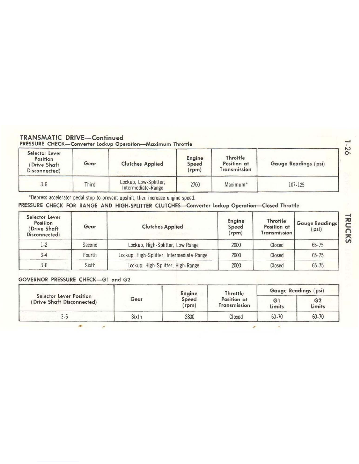
TRANSMATIC
DRIVE-Continued
PRESSURE
CHECK- Converter lockup Operation -
Maximum
Thrott
le
Se
lector Lever
Position
Engine
Throttle
(
Dri
ve Shaft
Gea
r
Clutches Appli ed Speed
Po
sition
at
Gauge
Readings (psi)
Disconnected
)
(rpm)
Transmission
3·6
Thi
rd
locku
p, low·
Splitter
,
2700
Maxi
mum*
107·115
Interme
dia
te
.Range
.-
----
*
Depress
accelerator pedal
stop
to preve
nt upshift
, t
hen
increase engi
ne s
peed
.
PRESSURE
CHECK
FOR
RANGE
AND
HIGH.
SPLITTER
CLUTCHES
- Converter
Lockup
Operation-Closed
Throllie
Selector
Lev
er
Throttle
Position
Engine
Gauge
Readings
(Drive
Shaft
Gear
Clutches Applied Speed Position at
( psi)
Disconnected}
(rpm) Transmission
]·2
Seco
nd locku
p, H
igh·S
plitter
, low Ran
ge
2000
Closed
65
·75
3·4
Fourth
l
ockup,
High·Splitter, Intermediate· Range
2000
Closed
65
·75
3·6
Sixt
h
lock
up,
High·Splitter, High·Ran
ge
2000
Closed
65·75
GOVERNOR
PRESSURE
CHECK-G1
and
G2
Engine Throttle
Gauge Readings (
psi
)
Selector
lever
Position
Gear
Speed
Position a t
G1
G2
(Drive Shaft Disconnected)
(rpm) Tr
ansmission
limits
Umits
3·6
Sixth
2800
Closed
60·70
60
·70
•
•
,
,
,
~
,
""
0-
-I
;00
c:
n
"
VI
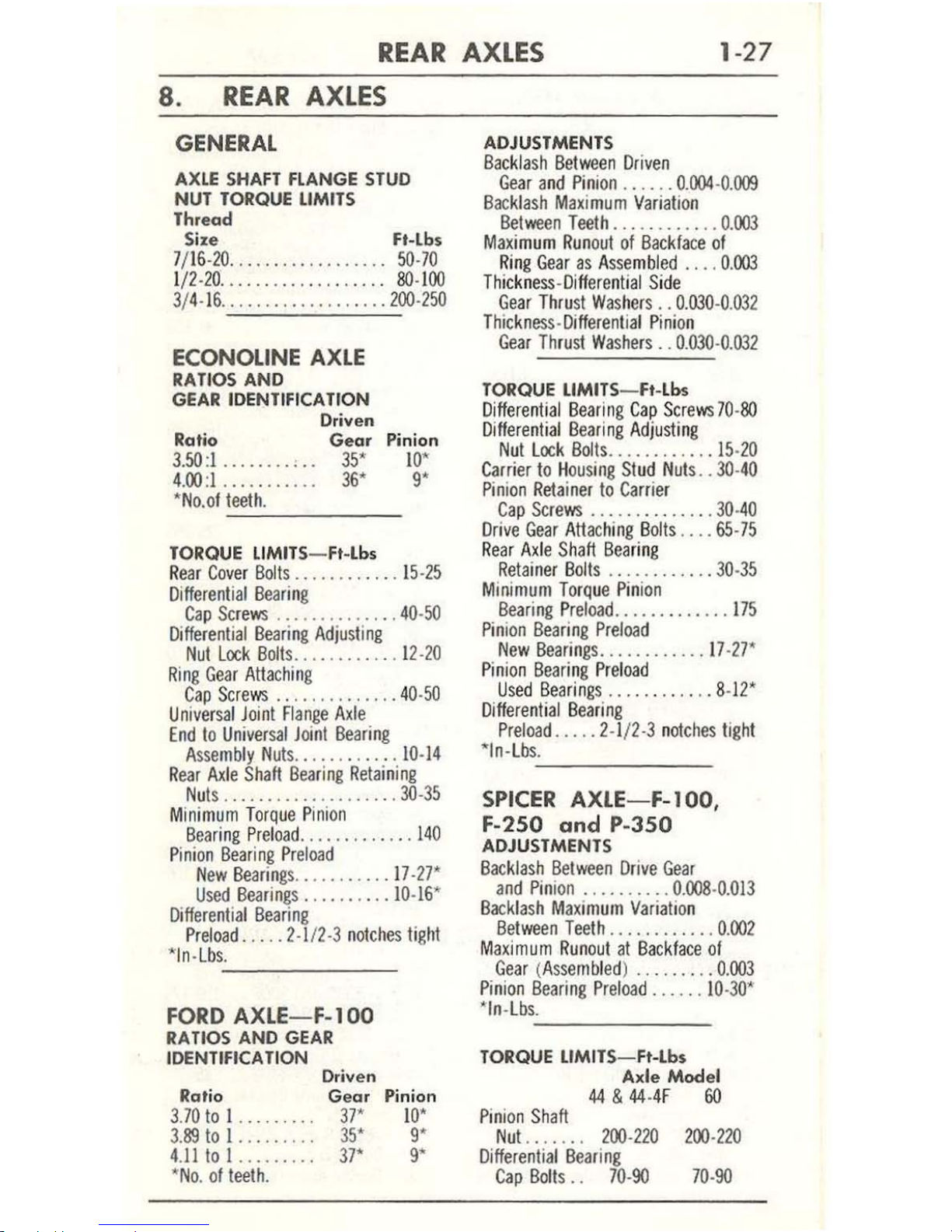
REAR
AXLES
1-27
8_
REAR
AXLES
GENERAL
AXLE
SHAFT
FLANGE
STUD
NUT
TORQUE
LIMITS
Thread
Size Ft-lhs
7/1
6-20
.............
.
.... 50-70
1
/2-20 ..........
....
.....
80·100
3/4-16
...................
200·250
ECONOLINE
AXLE
RATIOS AND
GEAR
IDENTIFICATION
Rat
io
3.50:1
........ , ..
4.
00:1
..........
.
'N
o.of teeth.
Driven
Gear
35'
36'
Pini
on
10
'
9'
------
TORQUE LIMITS-F.-Lb.
Re
ar
Cover
Bolls
.. ...
...
...
. 1
5-25
Differential
Beari
ng
Cap Sc
rews
..............
40
-50
Differential
Bearing
Adjusting
Nut
Lock
Bolts
............
12·
20
Ring
Gear
AUaching
Cap
Screws ..............
40-
50
Un
iversal Joinl Flange
Axle
End
to
Univers
al Joi
nl
Bearing
Assemb
ly
Nuts ............
10-14
R
ear
Axl
e Sh
aft
Bearing
Retaining
Nu
ts
.................
.. .
30-35
Minim
um
Torque P
inion
Bearing Preload
......
.......
140
Pin
ion
Bearing Preload
New
Bearings
........
...
17·27'
Used
Bearing
s ..
........
10
·16*
Differential
Bearing
Pr
eload .....
2·
112
·3
n
otches tight
*
In·Lbs.
'------
-
FORD
AXlE
-F-1 00
RA
Tl05
AND
GEAR
IDENTIFICATION
Dri
....
en
Rat
io
G
ear
Pinion
3.70
to
I
........
.
37*
1O~
3.89
to I ..
...
..
..
35' 9'
4.11
10 I ........
.
37'
9'
·No.
of
leeth.
ADJUSTMENTS
Backlash
Between
Driven
Gear
and
Pinion .. ..
..
0.
004-0.009
Backlash
Maximum Vari
atio
n
Between
Teeth
............
0.003
Maxim
um
Run
out
of
Backface
of
Ring
Gear
as Assembled
.... 0.003
Thickness-Differential Side
Gear
Thru
st Wash
ers
..
0.030
-0.
032
T
hickness-Different
ial Pinion
Gear Thru
st Washers
..
0.030-0.032
TORQUE
lIMITS
- F.-
Lbs
Di
fferentia
l B
earing
Cap
Screws
70-80
D
ifferenlial Bearing
Adjusting
Nut Lock Bmts ...
.......
..
15·20
Carrier
to H
ousing Stud
Nuts ..
30-40
Pinion
Reta
iner
to
Carrie
r
Cap
Screws
..........
_ .
..
30·40
Drive
Gear
AUaching Bolls ....
65-75
Re
ar
Axle Shaft
Bearing
Retainer Bolts
............
30-
35
Minimum
Torque
Pinion
Bearing Preload
.............
17
5
Pinion
Bea
ring
Preload
New
Bearings ............
17·27*
Pi
nion
Beari
ng
Preload
Us
ed
Bearings
..........
.. 8-12'
D
iffere
nti
al Bearing
Preload
.....
2.1/2·3
n
otches tigh
t
·In.Lb
s.:..,.
_____
_
SPICER
AXlE-F-IOO,
F-2S0
and
P-350
ADJUSTMENTS
Backlash
Belween
Drive
Gear
a
nd
Pinion
..........
0
.008·0.
013
Backlash
Maximum
Variatio
n
Belween
Tee
th
............
0.
002
Max
imum
Runout
at
Backface
of
Gear (Assemb
led)
.........
0.003
Pinion
Bearing
Prelo
ad ......
10
·30'
""n-lb
s.
-'----
---
TORQUE
lIMITS
- Ft-Lbs
Axte
Mod
et
44 & 44-4F
60
Pin
ion
Shaft
Nu
t . . . . .
..
200
-220
200
-220
Differential
Bearing
Cap
Bolls
. .
70-90
70-90
 Loading...