

Page 1
Page 2
Copyright © 2009, Forel Publishing Company, LLC, Woodbridge, Virginia
All Rights Reserved. No part of this book may be used or reproduced in any manner whatsoever
without written permission of Forel Publishing Company, LLC. For information write to Forel
Publishing Company, LLC, 3999 Peregrine Ridge Ct., Woodbridge, VA 22192
1961 Ford Thunderbird Shop Manual
EAN: 978-1-60371-011-4
ISBN: 1-60371-011-6
Forel Publishing Company, LLC
3999 Peregrine Ridge Ct.
Woodbridge, VA 22192
Email address: webmaster@ForelPublishing.com
Website: http://www.ForelPublishing.com
This publication contains material that is reproduced and distributed under a license from Ford
Motor Company. No further reproduction or distribution of the Ford Motor Company material is
allowed without the express written permission of Ford Motor Company.
NNoottee ffrroomm tthhee EEddiittoorr
This product was created from the original Ford Motor Company’s publication. Every effort has
been made to use the original scanned images, however, due to the condition of the material;
some pages have been modified to remove imperfections.
Although every effort was made to ensure the accuracy of this book, no representations or
warranties of any kind are made concerning the accuracy, completeness or suitability of the
information, either expressed or implied. As a result, the information contained within this book
should be used as general information only. The author and Forel Publishing Company, LLC
shall have neither liability nor responsibility to any person or entity with respect to any loss or
damage caused, or alleged to be caused, directly or indirectly by the information contained in
this book. Further, the publisher and author are not engaged in rendering legal or other
professional services. If legal, mechanical, electrical, or other expert assistance is required, the
services of a competent professional should be sought.
Disclaimer
Page 3
INDEX
GROUP
SERVICE
DEPARTMENT
FORD
DIVISION
FORD
MOTOR
COMPANY
FIRST
PRINTING
1900
FORD
MOTOR
COMPANY,
DEARBORN.
MICHIGAN
Reprinted
with
Ford
Motor Company's
Permission
Page 4
FOREWORD
This
manual
provides
information
for
the
proper
servicing
of
the
1961
Thunderbird.
The
descriptions
and
specifications
contained
in
this
manual
were
in
effect
at
the
time
the
manual
was
approved
for
printing.
The
Ford
Division
of
Ford
Motor
Company
reserves
the
right
to
discontinue
models
at
any
time,
or
change
specifications
or
design,
without notice
and
without
incurring
obligation.
SERVICE
DEPARTMENT
FORD
DIVISION
FORD
MOTOR
COMPANY
Page 5
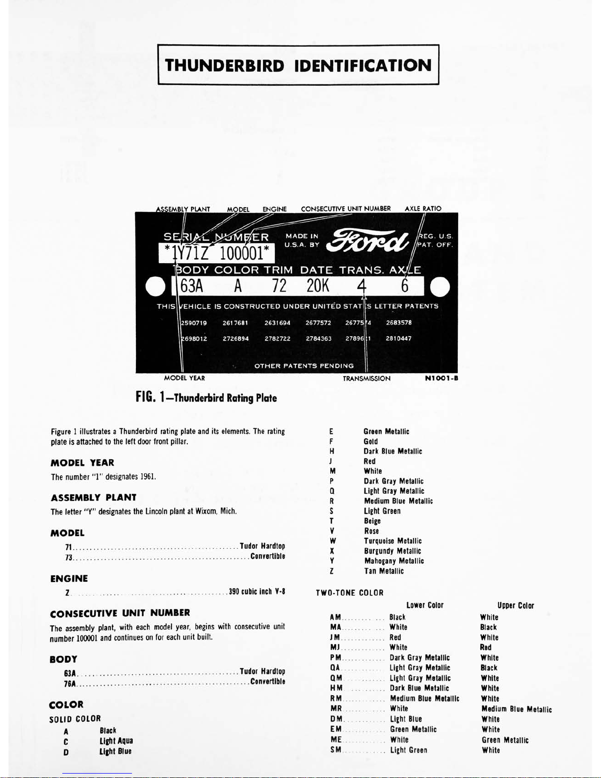
THUNDERBIRD
IDENTIFICATION
>EMBLY
PLANT
MODEL
ENGINE
CONSECUTIVE
UNIT
NUMBER
AXLE
RATIO
1Y71Z
100001
TP
MADE
IN
U.S.A.
BY
&&F<1'
*EG.
U.S.
'AT.
OFF.
BODY
COLOR
TRIM
DATE
TRANS.
A.
THIS
U/EHICLE
IS
CONSTRUCTED
UNDER
UNITED
STAT
CS
LETTER
PATENTS
2590719
2617681
2631694
2677572
26775ir4
2683578
'.698012
2726894
2782722
2784363
27896
1
2810447
OTHER
PATENTS
PENDING
MODEL
YEAR
FIG.
1
Thunderbird
Rating
Plate
TRANSMISSION
NIOOl-B
Figure
1
illustrates
a
Thunderbird
rating
plate
and
its
elements.
The
rating
plate
is
attached
to
the
left
door
front
pillar.
MODEL
YEAR
The
number
"1"
designates
1961.
ASSEMBLY
PLANT
The
letter
"Y"
designates
the
Lincoln
plant
at
Wixom,
Mich.
MODEL
71
Tudor
Hardtop
73
Convertible
ENGINE
1
390
cubic
inch
V-8
CONSECUTIVE
UNIT
NUMBER
The
assembly
plant,
with
each
model
year,
begins
with
consecutive
unit
number
100001
and
continues
on
for
each
unit
built.
BODY
53A
Tudor
Hardtop
70A
Convertible
COLOR
SOLID
COLOR
A
Black
C
Light
Aqua
D
Light
Blue
E
Green
Metallic
F
Gold
H
Dark
Blue
Metallic
J
Red
M
White
P
Q
R
Dark
Gray
Metallic
Light
Gray
Metallic
Medium
Blue
Metallic
S
T
V
Light
Green
Beige
Rose
W
Turquoise
Metallic
X
Y
z
Burgundy
Metallic
Mahogany
Metallic
Tan
Metallic
TWO-TONE
COLOR
Lower
Color
AM
Black
MA
White
JM
Red
MJ
White
PM
Dark
Gray
Metallic
QA
Light
Gray
Metallic
QM
Light
Gray
Metallic
HM
Dark
Blue
Metallic
RM
Medium
Blue
Metallic
MR
White
DM
Light
Blue
EM
Green
Metallic
ME
White
SM
Light
Green
Upper
Color
White
Black
White
Red
White
Black
White
White
White
Medium
Blue
Metallic
White
White
Green
Metallic
White
Page 6
TWO-TONE
COLOR-Continued
Lower
Color
Upper
Color
WM
Turquoise
Metallic
White
MW
White
Turquoise
Metallic
CM
Light
Aqua
White
TZ
Beige
Tan
ZM
Tan
White
MZ
White
Tan
YM
Mahogany
Metallic
White
FM
Gold
White
VA
Rose
Black
VM
Rose
White
XM
Burgundy
Metallic
White
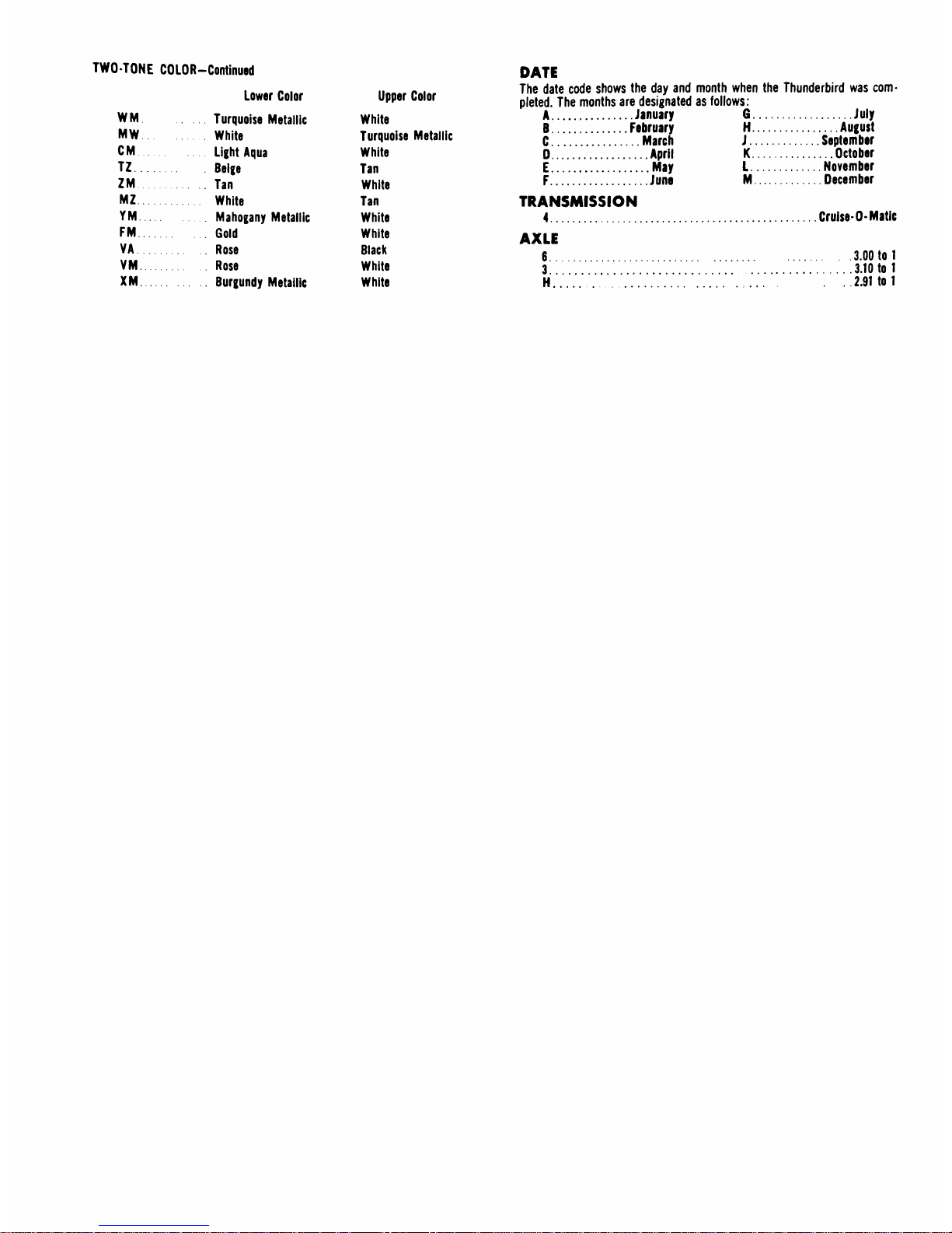
DATE
The
date
code
shows
the
day
and
month
when
the
Thunderbird
was
com
pleted.
The
months
are
designated
as
follows:
A
January
G
July
B
February
H
August
C
March
J
September
D
April
K
October
E
May
L
November
F
June
M
December
TRANSMISSION
4
AXLE
6
3..
H.
Cruise-O-Matic
3.00
to
1
3.10
to
1
2.91
to
1
Page 7
GROUP
I
ENGINE
AND
EXHAUST
SYSTEM
PAGE
PART
1-1
ENGINE
1.
P
A
RT
1-2
EXHAUST
SYSTEM
1-45
PART
1-3
SPECIFICATIONS
1-47
Page 8
12
Section
Page
1
Description
1-2
2
Engine
Trouble
Diagnosis.
.
1-6
3
Tune-Up
1-12
Engine
Compression
Test
.
1-13
Camshaft
Lobe
Lift
1-16
Valve
Clearance
1-16
Manifold
Vacuum
Test.
.
1-17
4
Engine
Removal
and
Installation
1-17
5
In-Chassis
Repair
Operations
1-19
Engine
Supports
1-19
Section
Page
Valve
Rocker
Aim
Shaft
Assembly
1-19
Intake
Manifold
1-21
Exhaust
Manifold
1-22
Regulator
Valve
Positive
Crankcase
Ventilation
System
1-23
Cylinder
Heads
and
Valves
1-23
Valve
Stem
Seal
Replacement
1-26
Cylinder
Front
Cover
and
Timing
Chain
1-27
Section
Page
Camshaft
1-29
Camshaft
Rear
Bearing
Bore
Plug
Replacement.
.
1-30
Hydraulic
Valve
Lifter
Replacement
1-30
Crankshaft
Lower
Rear
Oil
Seal
Replacement
1-31
Main
and
Connecting
Rod
Bearing
Replacement
1-32
Piston
and
Connecting
Rod
Assembly
1-32
Flywheel
1-36
Oil
Pan
and
Oil
Pump
..
.
1-36
Oil
Filter
Replacement.
.
.
1-36
6
Work
Stand
Repair
Operations
1-38
Crankshaft
1-38
Camshaft
Bearing
Replacement
1-40
Engine
Disassembly
1-40
Cylinder
Block
Cleaning
and
Inspection
1-42
Engine
Assembly
1-42
7
Crankcase
Ventilation
System
Maintenance
1-44
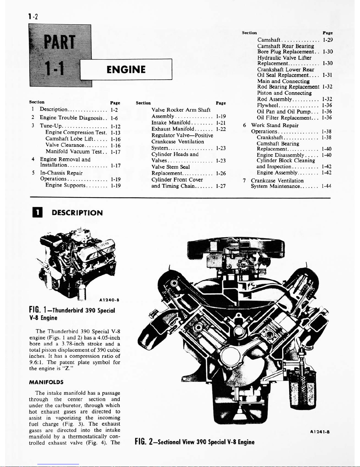
DESCRIPTION
A1240-B
FIG.
1
Thunderbird
390
Special
V-8
Engine
The
Thunderbird
390
Special
V-8
engine
(Figs.
1
and
2)
has
a
4.05-inch
bore
and
a
3.78-inch
stroke
and
a
total
piston
displacement
of
390
cubic
inches.
It
has
a
compression
ratio
of
9.6:1.
The
patent
plate
symbol
for
the
engine
is
"Z."
MANIFOLDS
The
intake
manifold
has
a
passage
through
the
center
section
and
under
the
carburetor,
through
which
hot
exhaust
gases
are
directed
to
assist
in
vaporizing
the
incoming
fuel
charge
(Fig.
3).
The
exhaust
gases
are
directed
into
the
intake
manifold
by
a
thermostatically
con
trolled
exhaust
valve
(Fig.
4).
The
A1241-B
FIG.
2
-Sectional
View
390
Special
V-8
Engine
Page 9

PART
1-1
-ENGINE
1-3
AIR
INLET
A1242-A
FIG.
3
Intake
Manifold
Exhaust
Gas
Passages
valve
is
located
at
the
outlet
of
the
right
exhaust
manifold.
When
the
valve
is
in
the
closed
or
heat
on
posi
tion,
part
of
the
exhaust
gases
are
di
rected
from
the
right
exhaust
mani
fold,
through
the
heat
riser
passage,
to
the
left
exhaust
manifold.
When
the
valve
is
open
or
in
the
heat
off
position,
more
of
the
exhaust
gases
from
the
right
manifold
are
permitted
OPEN
(HEAT
OFF)
CLOSED
(HEAT
ON)
A1073-A
FIG.
4
Exhaust
Gas
Control
Valve
4
1243-A
FIG.
5-lntake
Manifold
Fuel
Passages
AIR HEAT
CHAMBER
A
1206-
A
FIG.
6
Automatic
Choke
Heat
Chamber
to
flow
directly
out
of
the
exhaust
system
in
the
normal
manner.
The
intake
manifold
has
two
sets
of
fuel
passages,
each
with
its
own
separate
inlet
connection
to
the
car
buretor
(Fig.
5).
The
right
barrels
of
the
carburetor
feed Nos.
1,
4,
6,
and
7
cylinders
and
the
left
barrels
feed
Nos.
2,
3,
5,
and
8
cylinders.
The
distributor
is
mounted
at
the
left front
of
the
intake
manifold.
Warm
air
for
the
automatic
choke
is
drawn
from
the
heat
chamber
of
the
right
exhaust
manifold
(Fig.
6).
CYLINDER
HEADS
The
cylinder
head
assemblies
con
tain
the
valves
and
the
valve
rocker
arm
shaft
assembly.
The
combus
tion
chambers are
machined
in
the
head.
Valve
guides
are
an
integral
VALVE
OPEN
LIFTER
BODY
A1244-A
FIG.
7
-Valve
Port
Arrangement
part
of
the
head.
The
valves
are
ar
ranged
from
front
to
rear
on
both
banks
E-I-E-I-I-E-I-E
(Fig.
7).
CYLINDER
BLOCK
The
cylinders
are
numbered
from
front
to
rear,
on
the
right
bank
1,
2,
3
and
4
and
on
the
left
bank
5,
6,
7
and
8.
The
firing
order
is
1-5-4-2-6-3-
7-8.
The
oil
pump,
mounted
inside
the
oil
pan
at
the
front,
is
driven
by
the
distributor
through
an
intermediate
drive
shaft.
The
crankshaft
is
supported
by
five
main
bearings.
Crankshaft
end
thrust
is
controlled
by
the
flanges
of
the
No.
3
main
bearing.
The
pistons
have
two
compression
rings
and
one
oil
control
ring.
The
top
compression
ring
is
chrome-
plated
and
the
lower
compression
ring
is
phosphate-coated.
The
oil
con
trol
ring
assembly
consists
of
a
ser
rated
spring
and
two
chrome-plated
steel
rails.
VALVE
TRAIN
The
intake
and
exhaust
valve
as
semblies
are
the
rotating-type
which
VALVE
CLOSED
DISC
VALVE
BASE
CIRCLE
A1245-A
FIG.
8
Typical
Hydraulic
Valve
Lifter
Operation
Page 10
14
GROUP
1-
ENGINE
AND
EXHAUST
SYSTEM
rotate
each
time
the
valve
opens
and
closes.
The
push
rods
are
solid
steel
with
oil
cushioned
sockets.
The
camshaft
is
supported
by
five
bearings
pressed
into
the
block.
It
is
driven
by
a
sprocket
and
timing
chain
in
mesh
with
a
sprocket
on
the
crank
shaft.
Camshaft
end
play
is
controlled
by
a
thrust
button
and
spring
located
between
the
camshaft
sprocket
bolt
and
the
cylinder
front
cover.
An
ec
centric,
bolted
to
the
front
end
of
the
camshaft,
operates
the
fuel
pump.
Hydraulic
valve
lifters
are
used
which
provide
zero
valve
lash.
The
operation
and
parts
identification
of
the
hydraulic
valve
lifters
are
shown
in
Fig.
8.
When
the
valve
is
closed,
the
lifter
assembly
is
on
the
base
circle
of
the
camshaft
lobe
and
the
valve
push
rod
is
in
its
lowest
position.
With
the
lifter
assembly
in
this
position,
the
plunger
spring
expands
forcing
the
plunger
upward.
This
action
is
trans
mitted
to
the
valve
rocker
arm
via
the
valve
push
rod
until
there
is
solid
contact
between
the
valve
and
the
valve
end
of
the
valve
rocker
arm
(zero
valve
lash).
In
this
position,
the
oil
hole
in
the
lifter
and
plunger
is
indexed
with
the
lifter
oil
gallery
and
oil
is
forced
under
pressure
into
the
plunger.
This
creates
a
pressure
dif
ferential
above
and
below
the
valve
disc.
The
high
pressure
above
the
valve
disc
forces
the
valve
disc
open
and
the
oil
fills
the
area
below
the
plunger,
equalizing
the
pressure
on
each
side
of
the
valve
disc.
Whenever
clearance
between
the
valve
and
the
valve
rocker
arm
tends
to
be
present,
the
plunger
spring
expands
pushing
the
plunger
until
there
is
solid
contact
between
all
parts
of
the
valve
train
mech
anism.
As
the
camshaft
rotates
(valve
opening),
the
valve
lifter
is
raised
and
the
sudden
increase
in
oil
pres
sure
below
the
plunger
forces
the
valve
disc
closed
and
the
lifter
be
comes
a
hydraulic
ram.
During
this
period,
a
slight
leakage
of
oil
from
below
the
plunger
occurs.
As
the
high
point
on
the
camshaft
lobe
ro
tates
past
the
lifter,
the
push
rod
forces
the
valve
lifter
down
and
re
seats
the
valve.
The
pressure
on
the
oil
below
the
plunger
is
relieved
and
the
valve
disc
opens
so
that
the
chamber
can
again
be
filled.
This
cycle
is
repeated
for
each
revolution
of
the
camshaft.
Kd
if
-L
If
FIG.
9
Lubrication
System
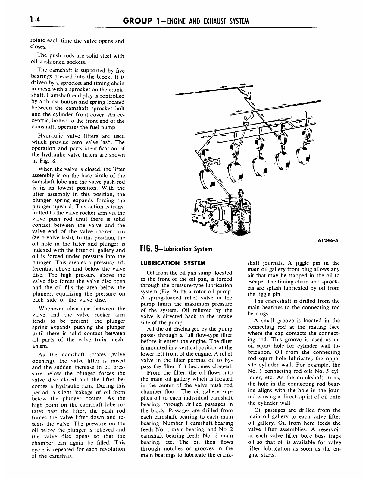
LUBRICATION
SYSTEM
Oil
from
the
oil
pan
sump,
located
in
the
front
of
the
oil
pan,
is
forced
through
the
pressure-type
lubrication
system
(Fig.
9)
by
a rotor
oil
pump.
A
spring-loaded
relief
valve
in
the
pump
limits
the
maximum
pressure
of
the
system.
Oil
relieved
by
the
valve
is
directed
back
to
the
intake
side
of
the
pump.
All
the
oil
discharged
by
the
pump
passes
through
a
full
flow-type
filter
before
it
enters
the
engine.
The
filter
is
mounted
in
a
vertical position
at
the
lower
left
front
of
the
engine.
A
relief
valve
in
the
filter
permits
oil
to
by
pass
the
filter
if
it
becomes
clogged.
From
the
filter,
the
oil
flows
into
the
main
oil
gallery
which
is
located
in
the
center
of
the
valve
push
rod
chamber
floor.
The
oil
gallery
sup
plies
oil
to
each
individual
camshaft
bearing,
through
drilled
passages
in
the
block.
Passages
are
drilled
from
each
camshaft
bearing
to
each
main
bearing.
Number
1
camshaft
bearing
feeds
No.
1
main
bearing,
and
No.
2
camshaft
bearing
feeds
No.
2
main
bearing,
etc.
The
oil
then
flows
through
notches
or
grooves
in
the
main
bearings
to
lubricate
the
crank-
A1246-A
shaft
journals.
A
jiggle
pin
in
the
main
oil
gallery
front
plug
allows
any
air
that
may
be
trapped
in
the
oil
to
escape.
The
timing
chain
and sprock
ets
are
splash
lubricated
by
oil
from
the
jiggle
pin.
The
crankshaft
is
drilled from
the
main
bearings
to
the
connecting
rod
bearings.
A
small groove
is
located
in
the
connecting
rod
at
the
mating
face
where
the
cap
contacts
the
connect
ing
rod.
This
groove
is
used
as
an
oil
squirt
hole
for
cylinder
wall
lu
brication.
Oil
from
the
connecting
rod
squirt
hole
lubricates
the
oppo
site
cylinder
wall.
For
example,
the
No.
1
connecting
rod
oils
No.
5
cyl
inder,
etc.
As
the
crankshaft
turns,
the
hole
in
the
connecting
rod
bear
ing
aligns
with
the
hole
in
the
jour
nal
causing
a
direct
squirt
of
oil
onto
the
cylinder
wall.
Oil
passages
are
drilled
from
the
main
oil
gallery
to
each
valve
lifter
oil
gallery.
Oil
from
here
feeds
the
valve
lifter
assemblies.
A
reservoir
at
each
valve
lifter
bore
boss
traps
oil
so
that
oil
is
available
for
valve
lifter
lubrication
as
soon
as
the
en
gine
starts.
Page 11
PART
1-1
-ENGINE
1-5
NO.
2
SUPPORT,
LEFT
HEAD
NO.
4
SUPPORT,
RIGHT
HEAD
FROM
NO.
2
CAMSHAFT
BEARING
TO
LEFT
CYLINDER
HEAD,
AND
FROM
NO.
4
CAMSHAFT
BEARING
TO
RIGHT
CYLINDER
HEAD,
A
1247-A
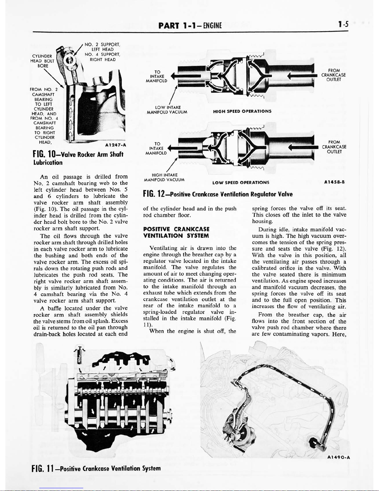
FIG.
10-Valve
Rocker
Arm
Shaft
Lubrication
An
oil
passage
is
drilled
from
No.
2
camshaft
bearing
web
to
the
left
cylinder
head
between
Nos.
5
and
6
cylinders
to
lubricate
the
valve
rocker
arm
shaft
assembly
(Fig.
10).
The
oil
passage
in
the
cyl
inder
head
is
drilled
from
the
cylin
der
head
bolt
bore
to
the
No.
2
valve
rocker
arm
shaft
support.
The
oil
flows
through
the
valve
rocker
arm
shaft
through
drilled
holes
in
each
valve
rocker
arm
to
lubricate
the
bushing
and
both
ends
of
the
valve
rocker
arm.
The
excess
oil
spi
rals
down
the
rotating
push
rods
and
lubricates
the
push
rod
seats.
The
right
valve
rocker
arm
shaft
assem
bly
is
similarly
lubricated
from
No.
4
camshaft
bearing
via
the
No.
4
valve
rocker
arm
shaft
support.
A
baffle
located
under
the
valve
rocker
arm
shaft
assembly
shields
the
valve
stems
from
oil
splash.
Excess
oil
is
returned
to
the
oil
pan
through
drain-back
holes
located
at
each
end
LOW
INTAKE
MANIFOLD
VACUUM
HIGH
SPEED
OPERATIONS
HIGH
INTAKE
MANIFOLD
VACUUM
LOW
SPEED
OPERATIONS
A1458-B
FIG.
12
Positive
Crankcase
Ventilation
Regulator
Valve
of
the
cylinder
head
and
in
the
push
rod
chamber
floor.
POSITIVE
CRANKCASE
VENTILATION
SYSTEM
Ventilating
air
is
drawn
into
the
engine
through
the
breather
cap
by
a
regulator
valve
located
in
the
intake
manifold.
The
valve
regulates
the
amount
of
air
to
meet
changing
oper
ating
conditions.
The
airisreturned
to
the
intake
manifold
through
an
exhaust
tube
which
extends
from
the
crankcase ventilation
outlet
at
the
rear
of
the
intake
manifold
to
a
spring-loaded
regulator
valve
in
stalled
in
the
intake
manifold
(Fig.
11).
When
the
engine
is
shut
off,
the
tt^^ft*
spring
forces
the
valve
off
its
seat.
This
closes
off
the
inlet
to
the
valve
housing.
During
idle,
intake
manifold
vac
uum
is
high.
The
high
vacuum
over
comes
the
tension
of
the
spring
pres
sure
and
seats
the
valve
(Fig.
12).
With
the
valve
in
this
position,
all
the
ventilating
air
passes
through
a
calibrated
orifice
in
the
valve.
With
the
valve
seated
there
is
minimum
ventilation.
As
engine
speed
increases
and
manifold
vacuum
decreases,
the
spring
forces
the
valve
off
its
seat
and
to
the
full
open
position.
This
increases
the
flow
of
ventilating
air.
From
the
breather
cap,
the
air
flows
into
the
front
section
of
the
valve
push
rod
chamber
where
there
are
few
contaminating
vapors.
Here,
&&%*
A1490-A
FIG.
11
Positive
Crankcase
Ventilation
System
Page 12

16
GROUP
1-
ENGINE
AND
EXHAUST
SYSTEM
the
incoming
air
has
a
chance
to
warm
up
before
contacting
contam
inating
vapors
originating
in
the
crankcase.
Warm
ventilating
air
mini
mizes
the
formation
of
crankcase
sludge.
The
ventilating
air
is
directed
by
a
baffle,
located
on
the
underside
of
the
intake
manifold,
upward
into
the
front
of
both
valve
rocker
arm
chambers.
The
baffle
also
directs
air
to
the
front
of
the
lower
crankcase
and
into
the
timing
chain
chamber.
Air
from
the
valve
rocker
arm
chamber
and
from
the
crankcase
flows
into
the
rear
of
the
valve
push
rod
chamber.
All
air
is
then
drawn
through
the
regulator
valve
and
is
discharged
into
the
intake
manifold.
COOUNO
SYSTEM
The
coolant
is
drawn
from
the
bottom
of
the
radiator
by
the
water
pump
which
delivers
the
coolant
to
the
cylinder
block
(Fig.
13).
The
coolant
travels
through
cored
passages
to
cool
the
entire
length
of
each
cylinder
wall.
Upon
reaching
the
rear
of
the
cylinder
block,
the
coolant
is
directed
upward
into
the
cylinder
heads
where
it
cools
the
combustion
chambers,
valves,
and
valve
seats
on
its
return
to
the
front
of
the
engine.
TO
RADIATOR
SUPPLY
TANK
FIG.
13
Cooling
System
The
coolant
from
each
cylinder
head
flows
through
the
water
pas
sages
in
the
intake
manifold
and
past
the
water
thermostat,
if
it
is
open,
into
the
radiator
supply
tank.
A1249-B
If
the
thermostat
is
closed,
a
small
portion
of
the
coolant
is
returned
to
the
water
pump
for
recirculation.
The
entire
system
is
pressurized
to
13-15
psi.
ENGINE
TROUBLE
DIAGNOSIS
Engine
performance
complaints
usually
fall
under
one
of
the
basic
headings
listed
in
the
"Engine
Trouble
Diagnosis
Guide."
When
a
particular
trouble
can
not
be
traced
to
a
definite
cause
by
a
simple
check,
the
possible
items
that
could
be
at
fault
are
listed
in
the
order
of
their
probable occurrence.
Check
the
items
in
the
order
listed.
For
example,
under
Poor
Acceleration,
the
ignition
system
is
listed
as
a
probable
cause
of
the
trouble.
All
the
ignition
system
items
that
affect
acceleration
are
listed.
Check
all
these
items
before
proceeding
to
the
next
probable
cause.
ENGINE
TROUBLE
DIAGNOSIS
GUIDE
ENGINE
WILL
NOT
CRANK
The
cause
of
this
trouble
is
usually
starter.
If
the
engine
cranks,
it
indi-
in
the
starting
system
(Part
10-2).
cates
that
water
is
leaking
into
the
If
the
starting
system
is
not
at
fault,
cylinders.
Remove
the
cylinder
check
for
a
hydrostatic
lock
or
a
head(s)
and
inspect
the
gaskets(s)
seized
engine
as
follows:
and/
or
head(s)
for
cracks.
Examine
Remove
the
spark
plugs,
then
at-
the
cylinder
block
for
cracks.
tempt
to
crank
the
engine
with
the
ENGINE
CRANKS
NORMALLY,
BUT
WILL
NOT
START
-
Check
the
fuel
supply.
If
there
is
fault
perform
the
following
test:
sufficient
fuel
in
the
tank,
the
cause
Disconnect
a
spark
plug
wire.
of
the
trouble
probably
lies
in
either
Check
the
spark
intensity
at
the
end
the
ignition
or
the
fuel
system.
of
the
wire
by
installing
a
terminal
To
determine
which
system
is
at
adapter
in
the
terminal
of
the
wire
CONTINUED
ON
NEXT
PAGE
Page 13
PART
1-1
-ENGINE
1-7
ENGINE
TROUBLE
DIAGNOSIS
GUIDE
(Continued)
ENGINE
CRANKS
NORMALLY,
BUT
WILL
NOT
START
(Continued)
to
be
checked.
Hold
the
adapter
ap
proximately
%e
inch
from
the
exhaust
manifold
and
crank
the
engine.
IF
THERE
IS
NO
SPARK
OR
A
WEAK
SPARK
AT
THE
SPARK
PLUGS
The
cause
of
the
trouble
is
in
the
ignition
system.
To
determine
if
the
cause
of
the
trouble
is
in
the
primary
or
the
secondary
circuit,
remove
the
coil
high
tension
lead
from
the
top
of
the
distributor
and
hold
it
approximately
Vie
inch
from
the
cylinder
head.
With
the
ignition
on,
crank
the
engine
and
check
for
a
spark.
If
the
spark
at
the
coil
high
ten
sion
lead
is
good,
the
cause
of
the
trouble
is
probably
in
the
distributor
cap
or
rotor.
If
there
is
no
spark
or
a
weak
spark
at
the
coil
high
tension
lead,
the
cause
of
the
trouble
is
probably
in
the
primary
circuit,
coil
to
dis
tributor
high
tension
lead,
or
the
coil.
IF
THERE
IS
A
GOOD
SPARK
AT
THE
SPARK
PLUGS
Check
the
spark
plugs.
If
the
spark
plugs
are
not
at
fault,
check
the
fol
lowing
items:
AUTOMATIC
CHOKE
Check
the
position
of
the
choke
plate.
If
the
engine
is
hot,
the
plate
should
be
open.
If
the
plate
is
not
open,
the
engine
will
load
up
due
to
the
excessively
rich mixture
and
will
not
start.
If
the
engine
is
cold,
the
plate
should
be
closed.
If
the
plate
is
not
operating
properly,
check
the
fol
lowing
items:
The
choke
linkage
for
binding.
The
fast
idle
cam
for
binding.
Thermostatic
spring
housing
ad
justment.
FUEL
SUPPLY
AT
THE
CARBURETOR
Work
the
throttle
by
hand
several
times.
Each
time
the
throttle
is
ac
tuated,
fuel
should
spurt
from
the
accelerating
pump
discharge
nozzles.
If
fuel
is
discharged
by
the
ac
celerating
pump,
the
engine
is
prob
ably
flooded,
or
there
is
water
in
the
fuel
system,
or
an
engine
me
chanical
item
is
at
fault.
If
fuel
is
not
discharged
by
the
accelerating
pump,
disconnect
the
carburetor
fuel
inlet
line
at
the
carburetor.
Use
a
suitable
container
to
catch
the
fuel.
Crank
the
en
gine
to
see
if
fuel
is
reaching
the
carburetor.
If
fuel
is
not
reaching
the
carbu
retor,
check:
The
fuel
filter.
The
fuel
pump.
The
carburetor
fuel
inlet
line
for
obstructions.
The
fuel
pump
flexible
inlet
line
for
a
collapsed
condition.
The
fuel
tank
line
for
obstruc
tions.
The
fuel
tank
vent.
If
fuel
is
reaching
the
carburetor,
check:
The
fuel
inlet
system
including
the
fuel
inlet
needle
and
seat
as
sembly,
and
the
float
assembly.
ENGINE
STARTS,
BUT
FAILS
TO
KEEP
RUNNING
FUEL
SYSTEM
Idle
fuel
mixture
needles
not
prop
erly
adjusted.
Engine
idle
speed
set
too
low.
The
choke
not
operating
properly.
Float
setting
incorrect.
Fuel
inlet
system
not
operating
properly.
Dirt
or
water
in
fuel
lines
or
in
the
fuel
filter.
Carburetor
icing.
Fuel
pump
defective.
Dirt
in
the
carburetor,
not
allowing
fuel
to
enter
or
be
discharged
from
the
idle
system.
IGNITION
SYSTEM
Leakage
in
the
high
tension
wiring.
ENGINE
RUNS,
BUT
MISSES
Determine
if
the
miss
is
steady
or
erratic
and
at
what
speed
the
miss
occurs
by
operating
the
engine
at
various
speeds
under
load.
MISSES
STEADILY
AT
ALL
SPEEDS
Isolate
the
miss
by
operating
the
engine
with
one
cylinder
not
firing.
CONTINUED
ON
NEXT
PAGE
Page 14
1-8
GROUP
1-
ENGINE
AND
EXHAUST
SYSTEM
ENGINE
TROUBLE
DIAGNOSIS
GUIDE
(Continued)
This
is
done
by
operating
the
engine
FUEL
SYSTEM
with
the
ignition
wire
removed
from
Float
setting
incorrect.
ENGINE
RUNS,
BUT
one
spark
plug
at
a
time,
until
all
Fuel
inlet
system
not
operating
MISSES
(Continued)
cylinders
have
been
checked.
Ground
properly.
the
spark
plug
wire
removed.
Dirt
or
water
in
fuel
lines
or
car
buretor.
Restricted
fuel
filter.
If
the
engine
speed
changes
when
a
particular
cylinder
is
shorted
out,
that
cylinder
was
delivering
power
COOLING
SYSTEM
before
being
shorted
out.
If
no
change
Check
the
cooling
system
for
in
in
the
engine
operation
is
evident,
the
ternal
leakage
and/
or
for
a
condi
miss
was
caused
by
that
cylinder
not
tion
that
prevents
the
engine
from
delivering
power
before
being
shorted
reaching
normal
operating
tempera
out.
In
this
case,
check
the:
ture.
ENGINE
IGNITION
SYSTEM
If
the
miss
is
isolated
in
a
particu
Perform
a
compression
test
to
de
termine
which
mechanical
compo
lar
cylinder,
perform
a
spark
test
on
nent
of
the
engine
is
at
fault
(page
the
ignition lead
of
that
cylinder.
1-13).
If
a
good
spark
does
not
occur,
the
trouble
is
in
the
secondary
cir
MISSES
AT
IDLE
ONLY
cuit
of
the
system.
Check
the
spark
FUEL
SYSTEM
plug
wire
and
the
distributor
cap.
Idle fuel
mixture
needles
not
prop
If
a
good
spark
occurs,
check
the
erly
adjusted.
spark
plug.
If
the
spark
plug
is
not
at
IGNITION
SYSTEM
fault,
a
mechanical
component
of
the
engine
is
probably
at
fault.
Excessive
play
in
the
distributor
shaft.
ENGINE
Worn
distributor
cam.
Perform
a
compression
test
to
de
ENGINE
termine
which
mechanical
compo
Perform
a
compression
test
to
de
nent
of
the
engine
is
at
fault
(page
termine
which
mechanical
compo
1-13).
nent
of
the
engine
isatfault
(page
1-13).
MISSES
ERRATICALLY
AT
ALL
SPEEDS
MISSES
AT
HIGH
SPEED
ONLY
EXHAUST
SYSTEM
Exhaust
system
restricted.
FUEL
SYSTEM
Power
valve
clogged
or
damaged.
IGNITION
SYSTEM
Low
or
erratic
fuel
pump
pressure.
Defective breaker
points,
con
Fuel
inlet
system
not
operating
denser,
secondary
wiring,
coil,
or
properly.
spark
plugs.
Restricted
fuel
filter.
High
tension
leakage
across
the
COOLING
SYSTEM
coil,
rotor,
or
distributor
cap.
Engine
overheating.
FUEL
SYSTEM
Power
valve
leaking
fuel.
ROUGH
ENGINE
IDLE
Engine
idle
speed
set
too
low.
Idle
fuel
system
air
bleeds
or
fuel
Idle
fuel
mixture
needles
not
prop
passages
restricted.
erly
adjusted.
Fuel
bleeding
from
the
accelerat
Float
setting
incorrect.
ing
pump
discharge
nozzles.
Air
leaks
between
the
carburetor
Secondary
throttle
plates
not
clos
and
the
manifold
and/or
fittings.
ing.
CONTINUED
ON
NEXT
PAGE
Page 15
PART
1-1
-ENGINE
1-9
ENGINE
TROUBLE
DIAGNOSIS
GUIDE
(Continued)
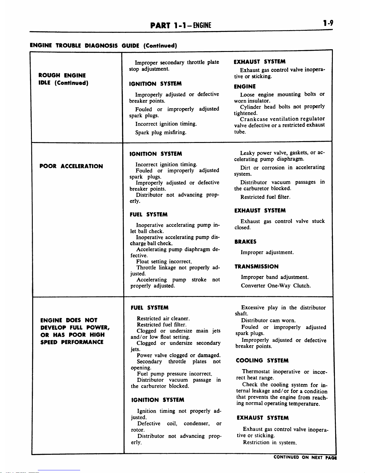
ROUGH
ENGINE
IDLE
(Continued)
Improper
secondary
throttle
plate
EXHAUST
SYSTEM
stop
adjustment.
Exhaust
gas
control
valve
inopera
tive
or
sticking.
IGNITION
SYSTEM
ENGINE
Improperly
adjusted
or
defective
Loose
engine
mounting
bolts
or
breaker
points.
worn
insulator.
Fouled
or
improperly
adjusted
Cylinder
head
bolts
not
properly
spark
plugs.
tightened.
r
r
Crankcase
ventilation
regulator
Incorrect
ignition
timing.
vajve
defective
or
a
restricted
exhaust
Spark
plug
misfiring.
tube.
POOR
ACCELERATION
IGNITION
SYSTEM
Leaky
power
valve,
gaskets,
or
ac
celerating
pump
diaphragm.
Incorrect
ignition
timing.
_.
i*:-
_
,
,
6
.
.
f
..
..
Dirt
or
corrosion
in
accelerating
Fouled
or
improperly
adjusted
spark
plugs.
^
Improperly
adjusted
or
defective
Distributor
vacuum
passages
in
breaker
points.
the
carburetor
blocked.
Distributor
not
advancing
prop-
Restricted
fuel
filter.
erly.
...
everru
EXHAUST
SYSTEM
FUEL
SYSTEM
Exhaust
gas
control
valve
stuck
Inoperative
accelerating
pump
in-
closed
let
ball
check.
Inoperative
accelerating
pump
dis
charge
ball
check.
BRAKES
PUmP
diaphragm
dC"
Improper
adjustment.
Float
setting
incorrect.
Throttle
linkage
not
properly
ad-
TRANSMISSION
^Accelerating
pump
stroke
not
Improper
band
adjustment.
properly
adjusted.
Converter
One-Way
Clutch.
ENGINE
DOES
NOT
DEVELOP
FULL
POWER,
OR
HAS
POOR
HIGH
SPEED
PERFORMANCE
FUEL
SYSTEM
Excessive
play
in
the
distributor
shaft.
Restricted
air
cleaner.
Distributor
cam
worn.
Restricted
fuel
filter.
Fou,ed
Qr
^^i
adjusted
Clogged
or
undersize
main
jets
k
.
and/
or
low
float
setting.
T
'.
,.
,
.
.
Clogged
or
undersize
secondary
.
ImProPerly
adJust^
or
defective
.
t
breaker
points.
Power
valve
clogged
or
damaged.
Secondary
throttle
plates
not
COOLING
SYSTEM
opening.
Fuel
pump
pressure
incorrect.
Thermostat
inoperative
or
incor-
Distributor
vacuum
passage
in
rect
heat
ran8e-
the
carburetor
blocked.
Check
the
cooling
system
for
in
ternal
leakage
and/or
for
a
condition
IGNITION
SYSTEM
that
Prevents
tne
en8'ne
from
reach
ing
normal
operating
temperature.
Ignition
timing
not
properly
ad
justed.
EXHAUST
SYSTEM
Defective
coil,
condenser,
or
rotor.
Exhaust
gas
control
valve
inopera-
Distributor
not
advancing
prop-
tive
or
sticking.
erly.
Restriction
in
system.
CONTINUED
ON
NEXT
PAGE
Page 16
1-10
GROUP
1-
ENGINE
AND
EXHAUST
SYSTEM
ENGINE
TROUBLE
DIAGNOSIS
GUIDE
(Continued)
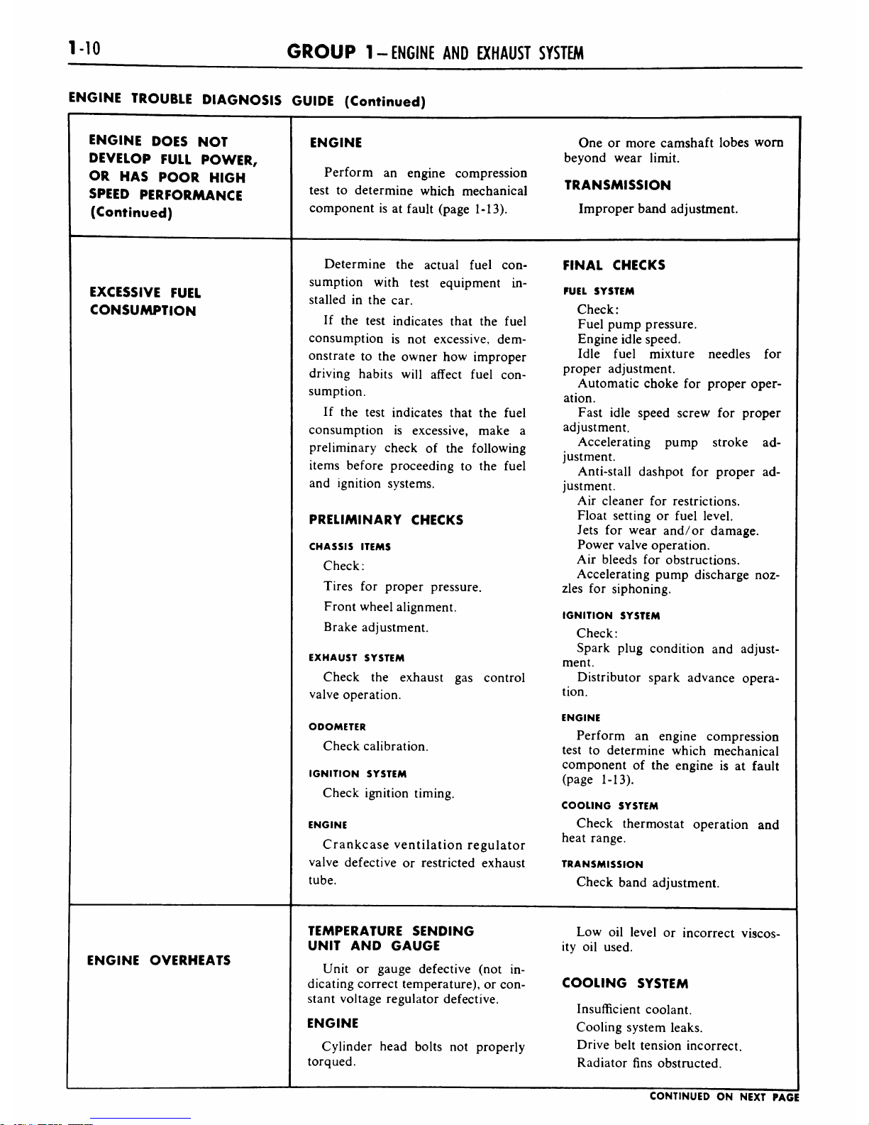
ENGINE
DOES
NOT
ENGINE
One
or
more
camshaft
lobes
worn
DEVELOP
FULL
POWER,
beyond
wear
limit.
OR
HAS
POOR
HIGH
Perform
an
engine
compression
TRANSMISSION
SPEED
PERFORMANCE
test
to
determine
which
mechanical
(Continued)
component
is
at
fault
(page
1-13).
Improper
band
adjustment.
Determine
the
actual
fuel
con
FINAL
CHECKS
sumption
with
test
equipment
in
EXCESSIVE
FUEL
stalled
in
the
car.
FUEL
SYSTEM
CONSUMPTION
Check:
If
the
test
indicates
that
the
fuel
Fuel
pump
pressure.
consumption
is
not
excessive,
dem
Engine
idle
speed.
onstrate
to
the
owner
how
improper
Idle
fuel
mixture
needles
for
driving
habits
will
affect
fuel
con
proper
adjustment.
sumption.
Automatic
choke
for
proper
oper
ation.
If
the
test
indicates
that
the
fuel
Fast
idle
speed
screw
for
proper
consumption
is
excessive,
make
a
adjustment.
preliminary
check
of
the
following
Accelerating
pump
stroke
ad
justment.
items
before
proceeding
to
the
fuel
Anti-stall
dashpot
for
proper
ad
and
ignition
systems.
justment.
Air
cleaner
for
restrictions.
PRELIMINARY
CHECKS
Float
setting
or
fuel
level.
Jets for
wear
and/or
damage.
CHASSIS
ITEMS
Power
valve
operation.
Check:
Air
bleeds
for
obstructions.
Accelerating
pump
discharge
noz
Tires
for
proper
pressure.
zles
for
siphoning.
Front
wheel
alignment.
IGNITION
SYSTEM
Brake
adjustment.
Check:
Spark
plug
condition
and
adjust
EXHAUST
SYSTEM
ment.
Check
the
exhaust
gas
control
Distributor
spark
advance
opera
valve
operation.
tion.
ENGINE
ODOMETER
Perform
an
engine
compression
Check
calibration.
test
to
determine
which
mechanical
IGNITION
SYSTEM
Check
ignition
timing.
component
of
the
engine
is
at
fault
(page
1-13).
COOLING
SYSTEM
ENGINE
Check
thermostat
operation
and
Crankcase
ventilation
regulator
heat
range.
valve
defective
or
restricted
exhaust
TRANSMISSION
tube.
Check
band
adjustment.
TEMPERATURE
SENDING
Low
oil
level
or
incorrect
viscos
UNIT
AND
GAUGE
ity
oil
used.
ENGINE
OVERHEATS
Unit
or
gauge
defective
(not
in
dicating
correct
temperature),
or
con
COOLING
SYSTEM
stant
voltage
regulator
defective.
Insufficient
coolant.
ENGINE
Cooling
system
leaks.
Cylinder
head
bolts
not
properly
Drive
belt
tension
incorrect.
torqued.
Radiator
fins
obstructed.
CONTINUED
ON
NEXT
PAGE
Page 17

PART
1-1
-ENGINE
1-11
ENGINE
TROUBLE
DIAGNOSIS
GUIDE
(Continued)
ENGINE
OVERHEATS
(Continued)
Thermostat
defective.
Thermostat
improperly
installed.
Cooling
system
passages
blocked.
Water
pump
inoperative.
IGNITION
SYSTEM
Incorrect
ignition
timing.
LOSS
OF
COOLANT
COOLING
SYSTEM
Leaking
radiator.
Loose
or
damaged
hose
connec
tions.
Water
pump
leaking.
Radiator
cap
defective.
Overheating.
ENGINE
Cylinder
head
gasket
defective.
Intake
manifold
to
cylinder
head
gasket
defective.
Cylinder
head
or
intake
manifold
bolts
not
properly
torqued.
Cylinder
block
core
plugs
leak
ing.
Temperature
sending
unit
leak
ing.
Cracked
cylinder
head
or
block,
or
warped
cylinder
head
or
block
gasket
surface.
ENGINE
FAILS
TO
REACH
NORMAL
OPERATING
TEMPERATURE
TEMPERATURE
SENDING
UNIT
AND
GAUGE
Unit
or
gauge
defective (not
in
dicating
correct
temperature)
or
con
stant
voltage
regulator
defective.
COOLING
SYSTEM
Thermostats
inoperative
or
of
in
correct
heat
range.
NOISY
HYDRAULIC
VALVE
LIFTER
A
noisy
valve
lifter
can
be
located
by
operating
the
engine
at
idle
speed
and
placing
a
finger
on
the
face
of
the
valve
spring
retainer.
If
the
lifter
is
not
functioning
prop
erly,
a
shock
will
be
felt
when
the
valve
seats.
Another
method
of
identifying
a
noisy
lifter
is
by
the
use
ofapiece
of
hose.
With
the
engine
operating
at
idle
speed,
place
one
end
of
the
hose
near
the
end
of
the
valve stem
and
the
other
end
to the
ear
and
listen
for
a
metallic
noise.
Repeat
this
procedure
on
each
intake
and
exhaust
valve
until
the
noisy
lift-
er(s)
has
been
located.
The
most
common
causes
of
hy
draulic
valve
lifter
troubles
are
dirt,
gum,
varnish,
carbon
deposits,
and
air
bubbles.
Dirt
in
the
lifter
assembly
can
prevent
the
disc
valve
from
seating,
or
it
may
become
lodged
between
the
plunger
and
body
surfaces.
In
either
case,
the
lifter
becomes
inop
erative
due
to
failure
to
"pump-up,"
or
because
the
internal
parts
are
no
longer
free
to
function
properly.
When
dirt
is
found
to
be
respon
sible
for
lifter
malfunction,
remove
the
lifter
assembly
and
thoroughly
clean
it.
Recommended
engine
oil
and
filter
change
intervals
should
be
followed
to
minimize
lifter
prob
lems
caused
by
dirt.
Deposits
of
gum
and
varnish
cause
similar
conditions
to
exist
which
may
result
in
lifter
malfunc
tion.
If
these
conditions
are
found
to
be
present,
the
lifter
should
be
disassembled
and
cleaned
in
solvent
to
remove
all
traces
of
deposits.
Air
bubbles
in
the
lubricating
oil,
caused
by
an
excessively
high
or
low
oil
level,
may
likewise
cause
lifter
malfunction.
A
damaged
oil
pick
up
tube
may
allow
air
to
be
drawn
into
the
lubricating
system.
To
check
for
the
presence
of
air,
remove
a
valve
rocker
arm
cover
and
note
the
condition
of
the
oil
as
it
flows
from
the
valve
rocker
arm
shaft
as
sembly.
Perform
corrective
action
as
required
to
remove
air
from
the
lubri
cating
oil.
Page 18

M2
GROUP
1-
ENGINE
AND
EXHAUST
SYSTEM
TUNE-UP
The
Tune-Up
Schedule
(Table
1)
is
for
either
an
A.
B,
or
C
tune-up.
Perform
all
operations
in
the
se
quence
listed.
The
recommended
mileage
interval
for
an
A
tune-up
is
4000
miles,
for
a
B
tune-up
it
is
8000
miles,
and
for
a
C
tune-up
it
is
12,000
miles.
For
a
detailed
descrip
tion
of
an
operation
procedure,
refer
to
the
operation
number
under
"Tune-Up
Procedure."
TUNE-UP
PROCEDURE
The
tune-up
is
divided
into
3
ma
jor
parts.
TABLE
1-Tune-Up
Schedule
The
first
part
is
performed
with
the
engine
not
operating.
The
first
step
consists
of
visual
and
mechani
cal
checks
and
adjustments.
The
sec
ond
step
consists
of
an
instrument
check.
Always
follow
the
instructions
of
the
manufacturer
of
the
test
equip
ment
used.
The
second
part
of
the
tune-up
covers
items
that
can
be
done
while
the
engine
is
warming
up
for
carbu
retor and
valve
adjustments.
The
third
part
of
the
tune-up
should
be
performed
with
the
engine
operating
at
normal
operating
tem
perature.
For
the
engine
to
reach
normal
operating
temperature,
it
should
be
operated
for
30
minutes
at
fast
idle
(1200
rpm).
For
more
detailed
information
on
corrective
action
to
be
taken
when
a
particular
defect
is
encountered,
re
fer
to
the
appropriate
part
of
the
manual.
At
the
end
of
the
"Tune-Up
Pro
cedure,"
additional
engine
checks
and
adjustments
are
described
for
use
as
necessary.
Operation
No.
Operation
ABC
ENGINE
NOT
OPERATING
MECHANICAL
CHECKS,
TESTS,
AND
ADJUSTMENTS
1
Clean,
adjust,
and
test
spark
plugs.
X
2
Take
a
compression
reading
of
each
cylinder.
X
3
Replace
spark
plugs.
X
4
Check
and
tighten
intake
manifold
bolts.
X
5
Check
and
adjust
the
deflection
of
the
drive
belts.
X
6
Replace
fuel
filter.
X
7
Check
and
adjust
carburetor
fuel
level.
X
8
Clean
the
distributor
cap
and
rotor.
X
X
9
Lubricate
the
distributor
cam,
lubricating
wick,
and
the
distributor
bushing.
X
10
Clean
battery
cables
and
terminals.
X
11
Clean
positive
crankcase
ventilation
system.
X
INSTRUMENT
CHECKS
12
'
Check
battery
state
of
charge.
x
Operation
No.
Operation
A
B
C
13
Check
and
adjust
breaker
point
dwell.
X
14
Check
and
adjust
spark
advance.
X
15
Perform
a
spark
intensity
test
of
each
spark
plug
wire.
X
16
Check
fuel
pump
pressure
and
capacity
X
WHILE
ENGINE
IS
WARMING-UP
17
Clean
carburetor
air
cleaner.
X
18
Inspect
the
radiator,
hoses,
and
engine
for
coolant
leaks.
X
19
Check
and
adjust
ignition
timing.
X
ENGINE
OPERATING
AT
NORMAL
TEMPERATURE
20
Adjust
accelerator
pump
link
to
seasonal
position.
X
21
Check
and
adjust
engine
idle
speed.
X
22
Check
and adjust
idle
fuel
mixture.
X
23
Check
and
adjust
anti-stall
dashpot
clearance.
X
Page 19

PART
1-1
-ENGINE
1-13
B1390-A
FIG.
14
Cleaning
Plug
Electrode
ENGINE
NOT
OPERATING
Perform
the
following
tests
with
the
engine
off
and
at
room
tempera
ture.
MECHANICAL
CHECKS,
TESTS,
AND
ADJUSTMENTS
1.
Clean,
Adjust,
And
Test
Spark
Plugs.
Remove
the
wire
from
each
spark
plug
by
grasping
the
moulded
cap
only.
Clean
the
area
around
each
spark
plug
with
compressed
air,
then
re
move
the
spark
plugs.
Clean
the
spark
plugs
onasand
blast
cleaner
following
the
equip
ment
manufacturer's
instructions.
Remove
carbon
and
other
deposits
from
the
threads
with
a
stiff
wire
brush.
Clean
the
electrode
surfaces
with
a
small
file
(Fig.
14).
Dress
the
electrode
to
secure
flat
parallel
sur
faces
on
both
the
center
and
side
electrode.
After
cleaning,
inspect
the
plug
for
a
cracked
or
broken
insulator,
badly
B1391-A
FIG.
15
Gapping
Spark
Plug
pitted
electrodes,
or
other
signs
of
failure.
Replace
as
required.
Set
the
gap
of
all
serviceable
or
new
plugs
to
0.032-0.036
inch
by
bending
the
ground
electrode
(Fig.
15).
After
the
gap
has
been
adjusted,
check
the
plugs
on
a
testing
machine.
Compare
the
sparking
efficiency
of
the
cleaned
and
gapped
plug
with
a
new
plug.
Replace
the
plug
if
it
fails
to
meet
requirements.
Apply
a
coat
ing
of
oil
to
the
shoulder
of
the
plug
where
the
insulator
projects
through
the
shell,
and
to
the
top
of
the
plug,
where
the
center
electrode
and
termi
nal
project
from
the
insulator.
Place
the
spark
plug
under
pressure.
Leak
age
is
indicated
by
air
bubbling
through
the
oil.
If
the
test
indicates
compression
leakage,
replace
the
plug.
If
the
plug
is
satisfactory,
wipe
it
clean.
Install
the
spark
plugs
and
torque
them
to
15-20
ft-lbs.
2.
Take
A
Compression
Reading
Of
Each
Cylinder.
Remove
the
spark
plugs.
Remove
the
coil
high
tension
lead
at
the
distributor
cap.
Set
the
primary
throttle
plates
and
choke
plate
in
the
wide
open
position.
Install
a
compression
gauge
in
No.
1
cylinder.
Using
a
remote
starter
switch,
crank
the
engine
several
times
and
record
the
highest
reading
recorded.
Note
the
number
of
compression
strokes
required
to
obtain
the
highest
reading.
Repeat
the
test
on
each
cylinder,
cranking
the
engine
the
same
num
ber
of
times
for
each
cylinder
as
was
required
to
obtain
the
highest
reading
on
the
No.
1
cylinder.
A
variation
of
20
pounds
from
specified
pressure
of
180
psiissatis
factory.
However,
the
compression
of
all
cylinders
should
be
uniform
within
10
pounds.
A
reading
of
more
than
the
allow
able
tolerance
above
normal
indi
cates
excessive
deposits
in
the
cyl
inder.
A
reading
of
more
than
the
allow
able
tolerance
below
normal
indi
cates
leakage
at
the
cylinder
head
gasket,
piston
rings,
or
valves.
A
low
even
compression
in
two
adjacent
cylinders
indicates
a
cylin
der
head
gasket
leak.
This
should
be
checked
before
condemning
the
rings
or
valves.
To determine
whether
the
rings
or
the
valves
are
at
fault,
squirt
the
equi
valent
of
a
tablespoon
of
heavy
oil
into
the
combustion
chamber.
Crank
the
engine
to
distribute
the
oil
and
repeat
the
compression
test.
The
oil
will
temporarily
seal
leakage
past
the
rings.
If
approximately
the
same
reading
is
obtained,
the
rings
are
satisfactory,
but
the
valves
are
leak
ing.
If
the
compression
has
increased
10
pounds
or
more
over
the
original
reading,
there
is
leakage
past
the
rings.
During
a
compression
test,
if
the
pressure
fails
to
climb
steadily
and
remains
the
same
during
the
first
two
successive
strokes,
but
climbs
higher
on
the
succeeding
strokes,
or
fails
to
climb
during
the
entire
test,
it
indi
cates
a
sticking
valve.
3.
Replace
Spark
Plugs.
Install
new
spark
plugs
of
the
correct
heat
range
(Part
2-3).
Torque
the
plugs
to
15-20
ft-lbs.
4.
Check
And
Tighten
Intake
Manifold
Bolts.
Check
all
intake
manifold
bolts
for
the
recommended
torque
of
32-35
ft-lbs.
Torque
the
bolts,
as
necessary,
starting
at
the
center
bolts
and
working
outward.
5.
Check
And
Adjust
The
Deflec
tion
Of
The
Drive
Belts.
Check
the
deflection
of
the
drive
belts
using
tool
33-73F.
Follow
the
instructions
of
the
gauge
manufacturer.
Adjust
the
tension
as
follows:
Loosen
the
generator
mounting
bolts
and
the
adjusting
bracket
bolt.
Move
the
generator
toward
or
away
from
the
engine
until
the
proper
de
flection
is
obtained
between
the
water
pump
pulley
and
the
generator
pulley.
Tighten
the
generator
adjust
ing
bracket
bolt
and
the
mounting
bolts.
6.
Replace
Fuel
Filter.
Slide
the
clamps
closest
to
the
filter
away
from
the
filter
(Fig.
16).
Slide
the
new
filter
into
the
rubber
connections
and
slide
the
clamps
into
H410-A
FIG.
16
Fuel
Filter
Installation
Page 20

1-14
GROUP
1-
ENGINE
AND
EXHAUST
SYSTEM
place.
Be
sure
the
fuel-flow
arrow
on
the
filter
are
pointed
toward
the
outlet
of
the
filter
(toward
the
carburetor).
7.
Check
And
Adjust
Carburetor
Fuel
Level.
Check
and
set
the
floats.
Refer
to
"Bench
Adjustments"
(Part
3-2).
8.
Clean
The
Distributor
Cap
And
Rotor.
Disconnect
the
coil
high
ten
sion
lead
and
the
spark
plug
wires
at
the
distributor
cap.
Remove
the
dis
tributor
cap
and
rotor.
Clean
the
inside
of
the
distributor
cap
and
clean
the
rotor
using
a
mild
cleaning
solvent
or
mineral
spirits
and
a
soft
bristle
brush.
Remove
dirt
or
corrosion
from
the
sockets
of
the
distributor
cap.
Inspect
the
cap
for
cracks,
burned
contacts,
or
perma
nent
carbon
tracks.
Inspect
the
rotor
for
cracks
or
a
burned
tip.
Replace
the
cap
and
/or
rotor
if
they
are
de
fective.
9.
Lubricate
The
Distributor
Cam,
Lubricating
Wick,
And
The
Distribu
tor
Bushing.
Apply
a
light
film
of
high-temperature,
non-fiber
grease
to
the
distributor
cam.
Do
not
use
en
gine
oil.
Saturate
the
lubricating
wick
with
SAE
10W
engine
oil.
Squirt
a
few
drops
of
SAE
10W
engine
oil
into
the
distributor
oil
cup.
10.
Clean
Battery
Cables
And
Terminals.
Disconnect
the
battery
cables.
Wash
the
battery
including
the
terminals
and
battery
carrier
in
cold
water
using
a
stiff
bristle
brush.
If
the
battery
is
extremely
dirty,
use
a
baking
soda
solution.
Inspect
the
bat
tery
cables
for
corrosion,
fraying,
or
breaks.
Apply
grease
to
the
battery
terminals
after
cleaning.
Connect
and
properly
tighten
the
cable
clamps.
11.
Clean
Positive
Crankcase
Ven
tilation
System.
Remove
the
crank
case
ventilation
regulator
valve,
ex
haust
tube,
and
connections.
Disas
semble
the
valve.
Clean
the
valve
and
exhaust
tube
in
clean
carburetor
solvent
and
dry
them
with
com
pressed
air.
Clean
the
rubber
hose
connections
with
a
low
volatility
petroleum
base
solvent
and
dry
them
with
compressed
air.
INSTRUMENT
CHECKS
Always
follow
the
instructions
of
the
test
unit
manufacturer
when
per
forming
instrument
checks.
All
the
tests
except
checking
distributor
spark
advance
can
be
made
in-
chassis.
Perform
the
tests
in
the
se
quence
listed.
12.
Check
Battery
State
of
Charge.
The
battery
state
of
charge
can
be
checked
by
measuring
the
battery
electrolyte
solution
specific
gravity
(hydrometer)
or
by
measur
ing
the
voltage
of
the
battery
cells
on
open
circuit
(no
current
flow)
with
a
battery
charge
tester.
If
a
hydrometer
is
used,
a
specific
gravity
of
1.275-1.285
indicates
a
fully
charged
battery.
1.230-1.240
indicates
approximately
60%
charge.
If
the
specific
gravity
varies
more
than
0.025
between
cells,
the
battery
should
be
replaced.
Refer
to
Part
10-1
which
de
scribes
in
detail
the
procedure
to
be
followed.
13.
Check
And
Adjust
Breaker
Point
Dwell.
If
the
contacts
are
ex
cessively
out of
alignment,
replace
the
breaker
point
assembly.
Do
not
attempt
to
align
used
breaker
points.
Install
a
new
breaker
point
assembly
if
necessary
(Part
2-2).
Use
a
dwell
meter
only
to
check
the
gap
of
used
breaker
points.
The
roughness
of
used
breaker
points
makes
an
accurate
gap
reading
or
setting
with
a
feeler
gauge
impos
sible.
Check
and
set
the
contact
dwell
to
specification
(Part
2-3)
by
follow
ing
the
instructions
of
the
meter
manufacturer.
Always
clean
used
points
before
adjusting.
14.
Check
And
Adjust
Spark
Ad
vance.
Refer
to
the
procedure
in
Part
2-1.
After
the
spark
advance
has
been
checked
and
adjusted,
install
the
rotor
and
position
the
distributor
in
the
block
so
that
the
rotor
is
aligned
with
the
mark
previously
scribed
on
the
distributor
body,
and
the
marks
on
the
body
and
engine
block
are
in
alignment.
Install
the
distributor
re
taining
screw(s).
Install
the
distribu
tor
cap.
Insert
each
distributor
wire
in
the
proper
distributor
cap
socket.
Be
sure
the
wires
are
forced
all
the
way
down
into
their
sockets.
The
No.
1
socket
is
identified
on
the
cap.
Starting
at
the
No.
1
socket,
install
the
wires
in
the
direction
of
distribu
tor
rotation
(counterclockwise)
in
the
firing
order
(1-5-4-8-6-3-7-2).
Push
all
weather
seals
into
position.
15.
Perform
A
Spark
Intensity
Test
Of
Each
Spark
Plug
Wire.
Check
the
spark
intensity
of
one
wire
at
a
time.
Install
a
terminal
adapter
in
the
terminal
of
the
wire
to
be
checked.
Hold
the
adapter
approxi
mately
%6
inch
from
the
exhaust
manifold
and
crank
the
engine
with
a
remote
starter
switch.
The
spark
should
jump
the
gap
regularly.
16.
Check
Fuel
Pump
Pressure
And
Capacity.
Disconnect
the
fuel
line
at
the
carburetor.
Install
a
pres
sure
gauge
(0-15
psi)
and
a
petcock
on
the
carburetor
fuel
inlet
line
(Fig.
17).
Vent
the
system,
by
opening
the
petcock
momentarily,
prior
to
taking
a
pressure
reading.
Operate
the
en-
FIG.
17
Fuel
Pump
Pressure
and
Capacity
Test
Page 21

PART
1-1
-ENGINE
1-15
gine
at
500
rpm.
After
the
pressure
has
stabilized,
it
should
be
4.0-6.0
psi.
Operate
the
engine
at
500
rpm.
Open
the
petcock
and
expel
the
fuel
into
a
suitable
container.
Observe
the
time
required
to
expel
one
pint.
It
should
be
within
20
seconds.
If
the
capacity
is
not
to
specifica
tions,
remove
the
fuel
filter
from
the
system
and
make
another
capacity
check.
If
the
capacity
is
within
specifica
tions
with
the
fuel
filter
removed,
the
fuel
filter
was
restricted
and
a
new
one
should
be
installed.
If
the
capacity
is
not
within
speci
fications
with
the
fuel
filter
removed,
the
fuel
pump
is
defective.
WHILE
ENGINE
IS
WARMING-UP
Place
the
transmission
selector
lever
in
neutral
position
and
set
the
parking
brake.
Start
the
engine
and
operate
it
at
1200
rpm
for
30
min
utes
to
stabilize
engine
temperatures.
While
the
engine
is
warming
up,
per
form
the
following
operations:
17.
Clean
Carburetor
Air
Cleaner.
Direct
clean
compressed
air
against
the
element
in
the
opposite
direction
of
normal
air
flow,
that
is,
from
the
inside
of
the
filter
out.
Clean
the
air
cleaner
body
and
cover
in
cleaning
solvent,
then
wipe
them
dry.
Do
not
install
the
air
cleaner
at
this
time.
18.
Inspect
the
Radiator,
Hoses,
and
Engine
For
Coolant
Leaks.
In
spect
the
radiator
hoses
for
cracks,
leaks,
and
a
collapsed
condition.
In
spect
the
radiator
and
engine
for
ex
ternal
leaks.
Check
for
internal
leakage
by
op
erating
the
engine
at
fast
idle
and
looking
for
the
formation
of
bubbles
in
the
radiator
supply
tank.
Oil
in
the
supply
tank
may
indicate
leakage
in
the
engine
block
or
a
leak
in
the
auto
matic
transmission
oil
cooler.
Water
formation
on
the
oil
level
dipstick
could
be
an
indication
of
internal
leakage.
19.
Check
And
Adjust
Ignition
Timing.
Disconnect
the
distributor
vacuum
line.
Connect
the
timing
light
high
tension
lead
to
the
No.
1
spark
plug
and
the
other
two
leads
of
the
timing
light
to
the
battery
terminals.
PUT
ROD
IN
OUTSIDE
HOLE
ACCELERATING
PUMP
STROKE
SUMMER
SETTING
WINTER
SETTING
ENGINE
IDLE
SPEED
SCREW
LOCK
NUT
ANTI-STALL
DASHPOT
CLEARANCE
B1424-A
FIG.
18
Carburetor
Idle
Adjustments
Do
not
puncture
the
spark
plug
wire
or
moulded
cap.
Clean
the
dirt
from
the
timing
marks
pin
on
the
crankshaft
damper.
If
necessary,
chalk
the
proper
mark
to
improve
legibility.
Operate
the
engine
at
idle
speed.
Be
sure
the
engine
is
idling
below
550
rpm
so
that
there
will
be
no
cen
trifugal
advance.
The
timing
light
should
flash
just
as
the
proper
mark
lines
up
with
the
pin
indicating
cor
rect
timing.
The
operator's
eye
should
be
in
line
with
the
center
of
the
damper
and
the
timing
pointer.
Refer
to
Part
2-3
for
the
correct
specifications.
ENGINE
OPERATING
AT
NORMAL
TEMPERATURE
20.
Adjust
Accelerator
Pump
Link
to
Seasonal
Position.
The
over-travel
lever
has
four
holes
and
the
acceler
ating
pump
link
has
two
holes
to
con
trol
the
accelerating
pump
stroke
for
different
engine
applications
(Fig.
1
8).
Install
the
accelerating
pump
op
erating
rod
in
the
No.
4
(top)
hole
for
winter
operation
or
in
the
No.
2
hole
for
summer
operation
in
the
over-
travel
lever.
Install
the
accelerating
pump
operating
rod
in
the
outside
hole
in
the
accelerating
pump
link
for
all
climatic
conditions.
On
cars
operating
constantly
in
areas
of
75
ambient
temperature
or
over,
install
the
accelerating
pump
operating
rod
in
the
No.
1
hole
in
the
over-travel
lever.
21.
Check
And
Adjust
Engine
Idle
Speed.
Final
engine
idle
speed
may
be
varied
to
suit
the
conditions
under
which
the
car
is
to
be
oper
ated.
On
a
car
with
an
air
conditioner,
operate
the
air
conditioner
for
20
minutes
before
setting
the
engine
idle
speed.
Adjust
the
engine
idle
speed
with
the
air
conditioner
operating.
Be
sure
the
parking
brake
is
on.
Place
the
transmission
selector
lever
in
drive
range
position.
Check
the
engine
idle
speed
and
adjust
it
to
drive
range
specifications
(450-475
rpm).
Place
the
selector
lever
in
neu
tral,
accelerate
the
engine
and
let
it
return
to
idle.
Place
the
selector
lever
in
drive
range
and
check
the
engine
idle
speed.
After
the
hot
engine
idle
speed
has
been
adjusted,
adjust
the
fast
idle
speed
by
aligning
the
step
of
the
fast
idle
cam
with
the
fast
idle
screw
(Fig.
19).
With
the
fast
idle
screw
resting
on
the
step,
turn
the
screw
in
to
obtain
1
700
rpm.
FAST
IDLE
ADJUSTING
SCREW
FAST
IDLE
CAM
B1425-A
FIG.
19
Carburetor
Fast
Engine
Idle
Speed
Adjustment
Page 22

1-16
GROUP
1-
ENGINE
AND
EXHAUST
SYSTEM
SOLID
TAPPET-TYPE
ADJUSTING
NEEDLES
B1426-A
FIG.
20
-Carburetor
Idle
Fuel
Mixture
Adjustment
22.
Check
And
Adjust
Idle
Fuel
Mixture
(Refer
to
Fig.
20).
Make
the
initial
mixture
adjustment
by
turning
the
needles
in
until
they
lightly
touch
the
seat,
then
back
them
off
1-1
Vi
turns.
Do
not
turn
a
needle
against
the
seat
tight
enough
to
groove
the
point.
If
a
needle
is
damaged,
it
must
be
replaced
before
a
proper
mixture
adjustment
can
be
obtained.
Turn
the
mixture
needles
in
until
the
engine
begins
to
run rough
from
the
lean
mixture.
Turn
the
needles
out
until
the
engine
begins
to
"roll"
from
the
rich
mixture.
Then
turn
the
needles
in
until
the
engine
runs
smoothly.
Always
favor
a
slightly
rich
mixture
rather
than
a
lean
mix
ture.
Check
the
engine
idle
speed.
23.
Check
And
Adjust
Anti-Stall
Dashpot
Clearance.
Loosen
the
anti-
stall
dashpot
lock
nut
(Fig.
18).
Hold
the
throttle
in
the
closed
position
and
depress
the
plunger
with
a
screw
driver
blade.
Turn
the
dashpot
in
its
bracket
inadirection
to
provide
a
clearance
of
0.060-0.090
inch
between
the
plunger
and
the
throttle
lever.
Tighten
the
lock
nut
after
the
adjustment
is
made.
ADDITIONAL
TESTS
AND
ADJUSTMENTS
CAMSHAFT
LOBE
LIFT
1.
Remove
the
air
cleaner
and
the
valve
rocker
arm
cover.
Remove
the
valve
rocker
arm
shaft
assembly
and
install
a
solid
tappet-type
push
rod
in
the
push
rod
bore
of
the
camshaft
lobe
to
be
checked.
2.
Make
sure
the
push
rod
is
in
the
lifter
push
rod
cup.
Install
a
dial
indicator
in
such
a
manner
as
to
have
the
actuating
point
of
the
indi
cator
in
the
push
rod
socket
and
in
the
same
plane
as
the
push
rod
move
ment
(Fig.
21).
Detail
1
Dial
Indicator
BE
SURE
TO
PLACE
Indicator
TIP
IN
CENTER
OF
PUSH ROD
SOCKET
A1202-A
FIG.
21
-Camshaft
Lobe
Lift
3.
Turn
the
crankshaft
damper
slowly
in
the
direction
of
rotation
until
the
lifter
is
on
the
base
circle
of
the
camshaft
lobe.
At
this
point,
the
push
rod
will
be
in
its
lowest
position.
4.
Zero
the
dial
indicator.
5.
Continue
to
rotate
the
damper
slowly
until
the
push
rod
is
in
the
fully
raised
position.
6.
Compare
the
total
lift
recorded
on
the
indicator
with
specifications.
7.
To
check
on
the
accuracy
of
the
original
indicator
reading,
continue
to
rotate
the
crankshaft
until
the
in
dicator
reads
zero.
8.
Remove
the
dial
indicator.
9.
Install
the
valve
rocker
arm
shaft.
Install
the
rocker
arm
cover
and
the
air
cleaner.
VALVE
CLEARANCE
A
0.060-inch
shorter
push rod
(color
coded
white)
or
a
0.060-inch
longer
push
rod
(color
coded
yel
low)
are
available
for
service
to
pro
vide
a
means
of
compensating
for
dimensional
changes
in
the
valve
mechanism.
Valve
stem
to
valve
rocker
arm
clearance
should
be
0.078-0.218
inch
with
the
hydraulic
lifter
completely
collapsed.
Repeated
valve
reconditioning
operations
(valve
and/or
valve
seat
refacing)
will
de
crease
this
clearance
to
the
point
that
if
not
compensated
for,
the
hydraulic
valve
lifter
will
cease
to
function.
To
determine
whether
a
shorter
or
a
longer
push
rod
is
necessary,
make
the
following
check:
1.
Position
the
crankshaft
as
out
lined
in
steps
5
and
6.
2.
Position
the
hydraulic
lifter
compressor
tool
on
the
rocker
arm
and
slowly
apply
pressure
to
bleed
down
the
hydraulic
lifter
until
the
plunger
is
completely
bottomed (Fig.
FIG.
22
Valve
Clearance
22).
Hold
the
lifter
in
the
fully
col
lapsed
position.
3.
Insert
the
correct
end
of
the
clearance
gauge
between
the
valve
stem
and
the
rocker
arm
of
the
valve
being
checked.
4.
If
the
first
step
of
the
gauge
en
ters,
a
standard
length
push rod
may
be
used.
If
the
first
step
of
the
gauge
does
not
enter,
replace
the
standard
push
rod
with
a
0.060-inch
shorter
service
push rod.
If
the
second
step
of
the
gauge
enters,
the
operating
range
of
the
lifter
is
excessive.
This
indicates
that
the
incorrect
push
rod
has
been
in
stalled
or
severe
wear
has
occurred
at
the
push
rod
ends,
rocker
arm,
or
valve
stem.
In
this
case,
it
will
be
nec
essary
to
determine
the
area
of
dis
crepancy
and
the
incorrect
or
defec
tive
part(s)
should
be
replaced.
If
all
the
valve
train
components
except
the
push
rod
are
within
limits,
install
a
0.060-inch
longer
push
rod.
5.
Rotate
the
crankshaft
until
No.
1
piston
is
on
TDC
at
the
end
of
the
compression
stroke.
With
No.
1
piston
on
TDC,
check
the
follow
ing
valves:
No.
1
Intake
No.
1
Exhaust
No.
3
Intake
No.
4
Exhaust
No.
7
Intake
No.
5
Exhaust
No.8Intake
No.
8
Exhaust
6.
Position
No.
6
piston
on
TDC
and
check
the
following
valves:
No.
2
Intake
No.
2
Exhaust
No.4Intake
No.
3
Exhaust
No.
5
Intake
No.
6
Exhaust
No.6Intake
No.
7
Exhaust
When
compressing
the
valve
spring
to
remove
push
rods,
be
sure
the
pis
ton
in
the
individual
cylinder
is
below
Page 23

PART
1-1
-ENGINE
1-17
TDC
to
avoid
contact
between
the
valve
and
the
piston.
To
replace
a
push
rod,
it
will
be
necessary
to
remove
the
valve
rocker
arm
shaft
assembly.
Upon
replacement
of
a
valve
push
rod
and/
or
valve
rocker
arm
shaft
assembly,
the
engine
should
not
be
cranked
or
rotated
until
the
hydraulic
lifters
have
had
an
opportunity
to
leak
down
to
their
normal
operating
position.
The
leak-down
rate
can
be
accelerated
by
using
the
tool
shown
in
Fig.
22
on
the
valve
rocker
arm
and
applying
pressure
in
a
direction
to
collapse
the
lifter.
MANIFOLD
VACUUM
TEST
A
manifold
vacuum
test
aids
in
determining
the
condition
of
an
en
gine
and
also
in
helping
to
locate
the
cause
of
poor
engine
performance.
To
test
manifold
vacuum:
1.
Operate
the
engine
for
a
mini
mum
of
30
minutes
at
1200
rpm.
2.
Install
an
accurate,
sensitive
vacuum
gauge
in
the
fitting
in
the
in
take
manifold.
3.
Operate
the
engine
at
recom
mended
idle
rpm,
with
the
transmis
sion
selector
lever
in
neutral.
4.
Check
the
vacuum
reading
on
the
gauge.
TEST
CONCLUSIONS
Manifold
vacuum
is
affected
by
carburetor
adjustment,
valve
timing,
TABLE
2
Manifold
Vacuum
Gauge
Readings
Gauge
Reading
Engine
Condition
18
inches
Normal.
Low
and
steady.
Loss
of
power
in
all
cylinders
caused
possibly
by
late
ignition
or
valve
timing,
or
loss
of
compression
due
to
leakage
around
the
piston
rings.
Very
low.
Manifold,
carburetor,
or
cylinder
head
gasket
leak.
Needle
fluctuates
steadily
as
speed
increases.
A
partial
or
complete
loss
of
power
in
one
or
more
cylinders
caused
by
a
leaking
valve,
cyl
inder
head
or
intake
manifold
gasket
leak,
a
defect
in
the
ignition
system,
or
a
weak
valve
spring.
Gradual
drop
in
reading
at
engine
idle.
Excessive
back
pressure
in
the
exhaust
system.
Intermittent
fluctuation.
An
occasional
loss
of
power
possibly
caused
by
a
defect
in
the
ignition
system
or
a
sticking
valve.
Slow
fluctuation
or
drifting
of
the
needle.
Improper
idle
mixture
adjustment,
carburetor
or
intake
manifold
gasket
leak,
or
possibly
late
valve
timing.
the
condition
of
the
valves,
cylinder
compression,
and
leakage
of
the
man
ifold,
carburetor,
or
cylinder
head
gaskets.
Because
abnormal
gauge
readings
may
indicate
that
more
than
one
of
the
above
factors
is
at
fault,
exercise
caution
in
analyzing
an
abnormal
reading.
For
example,
if
the
vacuum
is
low,
the
correction
of
one
item
may
increase
the
vacuum
enough
to
indi
cate
that
the
trouble
has
been
cor
rected.
It
is
important,
therefore,
that
each
cause
of
an
abnormal
read
ing
be
investigated
and
further
tests
conducted
where
necessary
in
order
to
arrive
at
the
correct
diagnosis
of
the
trouble.
Table
2
lists
various
types
of
read
ings
and
their
possible
causes.
Allowance
should
be
made
for
the
effect
of
altitude
on
the
gauge
read
ing.
The
engine
vacuum
will
decrease
with
an
increase
in
altitude.
ENGINE
REMOVAL
AND
INSTALLATION
The
procedures
given
are
for
the
engine
without
the
transmission
attached.
If
the
engine
and
transmis
sion
are
removed
as
an
assembly,
in
stall
standard
eye
bolts
with
Vi-IA
threads
in
the
bosses
at
the
top
rear
of
the
exhaust
manifolds.
Then
at
tach
the
engine
lifting
bracket
and
sling
to
the
eye
bolts.
The
engine
in
stallation
is
shown
in
Fig.
23.
REMOVAL
1.
Drain
the
cooling
system
and
the
crankcase.
Remove
the
hood
and
the
air
cleaner.
2.
Disconnect
the
radiator
upper
hose
at
the
radiator
supply
tank
and
the
radiator
lower
hose
at
the
water
pump.
3.
Disconnect
the
transmission
oil
cooler
lines
at
the
radiator.
Remove
the
radiator
and
support
as
an
assem
bly.
4.
Disconnect
the
battery
ground
cable
at
the
generator
mounting
bracket. Remove
the
oil
level
dipstick
and
the
ignition
coil.
5.
Disconnect
the
oil
pressure
sending
unit
wire
at
the
sending
unit
and
the
flexible
fuel
line
at
the
fuel
tank
line.
6.
Remove
the
wire
loom
from
the
clips
on
the
left
valve
rocker
arm
cover
and
position
the
wires
out
of
the
way.
7.
Disconnect
the
three
windshield
washer
lines
at
the
washer
pump
and
position
them
out
of
the
way.
8.
Disconnect
the
accelerator
rod
at
the
carburetor.
Remove
the
accel
erator
retracting
spring.
Remove
the
accelerator
cross
shaft
bracket
from
the
intake
manifold
and
position
it
out
of
the
way.
9.
Disconnect
the
power
steering
pump
bracket
from
the
water
pump,
then
wire
the
power
steering
pump
to
the
hood
left
hinge
in
a
position
that
will
prevent
the
oil
from
draining
out.
10.
Disconnect
the
power
brake
line
at
the
intake
manifold
and
at
the
flexible
line.
Release
the
line
from
the
Page 24

1-18
GROUP
1-
ENGINE
AND
EXHAUST
SYSTEM
FIG.
23
Engine
Installation
brackets
on
the
left
valve
rocker
arm
cover
and
remove
the
line.
On
a
car
with
an
air
conditioner,
disconnect
the
magnetic
clutch
wire.
Isolate
the
compressor.
11.
Disconnect
the
heater
hose
at
the
water
pump
and
at
the
intake
manifold.
12.
Disconnect
the
generator
wires
at
the
generator.
13.
Disconnect
the
water
tem
perature
sending
unit
wire
at
the
sending
unit.
14.
Remove
the
engine
ground
strap
and
the
starter
cable
retaining
bracket
from
the
generator
mounting
bracket.
15.
Raise
the
front
of
the
car.
16.
Remove
the
starter
and
dust
seal
and
the
transmission
fluid
filler
tube
bracket.
17.
Disconnect
the
muffler
inlet
pipes
from
the
exhaust
manifolds,
and
the
engine
right
and
left
support
insulators
at
the
engine.
18.
Remove
the
converter
hous
ing
lower
access
cover
and
the
cover
assembly.
Remove
the
flywheel
to
converter
nuts.
Secure
the
con
verter
assembly
in
the
housing.
Re
move
the
converter
housing
to
en
gine
lower
bolts,
and
remove
the
oil
A1479-A
cooler
lines
retaining
clamp
from
the
engine
block.
19.
Lower
the
car,
then
support
the
transmission.
Remove
the
con
verter
housing
upper
retaining
bolts.
20.
Install
the
engine
left
lifting
bracket
on
the
front
of
the
left
cyl
inder
head
where
the
coil
mounts.
Install
the
engine
right
lifting
brack
et
at
the
rear
of
the
right
cylinder
head.
Attach
the
engine
lifting
sling
(Fig.
24).
21.
Raise
the
engine
slightly
and
carefully
pull
it
from
the
transmis
sion.
22.
Lift
the
engine out
of
the
en
gine
compartment
and
install
it
on
a
work
stand
(Fig.
25).
INSTALLATION
1.
Position
the
exhaust
gas
control
valve,
with
a
new
gasket
on
each
side,
on
the
right
exhaust
manifold
studs.
Temporarily
tie
the
valve
to
the
manifold.
Place
a
new
gasket
over
the
studs
of
the
left
exhaust
manifold.
2.
Attach
the
engine
lifting
brack
ets
and
sling
(Fig.
24).
Remove
the
engine
from
the
work
stand.
3.
Lower
the
engine
carefully
into
the
engine
compartment.
Make
sure
the
exhaust
manifolds
are
properly
A1251-B
FIG.
24
Engine
Lifting
Brackets
and
Sling
aligned
with
the
muffler
inlet
pipes
and
the
dowels
in
the
block
engage
the
holes
in
the
converter
housing.
Start
the
converter
pilot
into
the
crankshaft.
4.
Install
the
converter
housing
upper
bolts.
Torque
the
bolts
to
specifications.
5.
Start
the
engine
right
and
left
support
insulator
to
engine
bolts.
Disconnect
the
engine
lifting
sling
and
remove
the
lifting
brackets.
6.
Raise
the
front
of
the
car.
In
stall
the
converter
housing
lower
re
taining
bolts.
Torque
the
bolts
to
specifications.
7.
Remove
the
retainer
securing
the
converter
in
the
housing. Install
the
flywheel
to
converter
lockwashers
and
nuts.
Torque
the
nuts
to
speci
fications.
Install
the
converter
lower
access
plate
and
the
housing
cover
assembly.
Install
the
oil
cooler
lines
retaining
clamp.
8.
Torque
the
engine
front
support
insulator
bolts
to
45-50
ft-lbs
torque.
9.
Remove
the
retainer
securing
the
exhaust
gas
control
valve.
Con
nect
both
exhaust
manifolds
to
the
muffler
inlet
pipes.
Torque
the
nuts
to
specifications.
10.
Position
the
dust
seal
and
in-
A1252-A
FIG.
25-Engine
Work
Stand
Page 25

PART
1-1
-ENGINE
1-19
stall
the
starter
and
the
transmission
fluid
filler
tube
bracket.
11.
Remove
the
support
from
the
transmission
and
lower
the
car.
12.
Connect
the
generator
wires.
13.
Connect
the
water
tempera
ture
sending
unit
wire.
Connect
the
heater
hose
at
the
intake
manifold.
14.
Connect
the
engine
ground
strap
and
install
the
starter
cable
re
taining
clamp.
15.
Connect
the
flexible
fuel
line,
the
oil
pressure
sending
unit
wire,
and
the
windshield
wiper
vacuum
line.
16.
Install
the
ignition
coil
and
connect
the
coil
primary
and
high
tension
wires.
17.
Install
the
oil
level
dipstick.
18.
Position
the
wire
loom
in
the
retaining
clips
on
the
left
valve
rocker
arm
cover.
19.
Connect
the
windshield
wash
er
pump
lines.
20.
Install
the
accelerator
cross
shaft
bracket
and
the
accelerator
re
tracting
spring.
Connect
the
accelera
tor
rod.
21.
Connect
the
power
steering
pump
bracket
to
the
water
pump.
22.
Connect
the
power
brake
line
to
the
intake
manifold
and
to
the
flex
ible
line.
Install
the
line
in
the
retain
ing
clips
on
the
left
valve
rocker
arm
cover.
On
a
car
with an
air
conditioner,
connect
the
magnetic
clutch
wire
and
the
compressor
lines.
23.
Install
the
radiator
and
sup
port
as
an
assembly.
Connect
the
radiator
upper
and
lower
hoses.
Con
nect
the
transmission
oil
cooler
lines.
24.
Fill
and
bleed
the
cooling
sys
tem.
Connect
the
heater
hose
at
the
water
pump.
25.
Fill
the
crankcase
with
the
proper
grade and
quantity
of
engine
oil.
26.
Operate
the
engine
at
fast
idle
and
check
all
gaskets
and
hose
con
nections
for
leaks.
27.
Adjust
the
transmission
con
trol
linkage.
Install
the
air
cleaner.
28.
Install
and
adjust
the
hood.
IN-CHASSIS
REPAIR
OPERATIONS
ENGINE
SUPPORTS
The
front
supports
are
located
on
each
side
of
the
crankcase
and
the
rear
support
is
located
at
the
trans
mission
extension
housing.
ENGINE
FRONT
SUPPORT
The
engine
front
support
is
shown
in
Fig.
26.
The
procedures
given
ap
ply
to
either
a
right
or
left
installa
tion.
Removal
1.
Remove
the
insulator
assembly
to
engine
retaining
bolts,
and
insula
tor
to
underbody
retaining
nut.
If
only
one
support
is
being
re
moved,
loosen
the
other
support.
2.
Raise
the
engine
about
1
inch
with
a
jack
and
a
block
of
wood
SUPPORT
BRACKET
INSULATOR
ASSEMBLY
A1480-A
FIG.
26
Engine
Front
Support
placed
under
the
oil
pan,
then
re
move
the
insulator
assembly.
Installation
1.
Position
the
insulator
assembly.
Install,
but
do
not
tighten,
the
insula
tor
to
engine
lockwashers
and
bolts.
If
both
supports
have
been
removed,
install
the
bolts
on
the
opposite
side
before
proceeding
with
step
2.
2.
Lower
the
engine,
then
install
the
underbody
to
insulator
nut.
Torque
the
nut
to
45-50
ft-lbs.
Torque
the
insulator
to
engine
bolts
to
45-50
ft-lbs.
ENGINE
REAR
SUPPORT
The
engine
rear
support
is
shown
in
Fig.
27.
Removal
1.
Remove
the
support
retainer
bolts
and
washers
and
remove
the
re
tainer.
2.
Raise
the
extension
housing
slightly
to
relieve
the
pressure
on
the
support
assembly.
Remove
the
sup
port
assembly.
Installation.
Raise
the
extension
housing
enough
to
position
the
sup
port
assembly
and
retainer.
Install
the
support
retainer
to
extension
housing
washers
and
bolts.
Torque
the
support
retainer
bolts
to
45-50
ft-
lbs.
VALVE
ROCKER
ARM
SHAFT
ASSEMBLY
REMOVAL
1.
Operate
the
engine
until
normal
operating
temperature
has
been
reached.
Remove
the
air
cleaner.
2.
Disconnect
the
spark
plug
wires
at
the
spark
plugs.
Remove
the
wires
from
the
bracket
on
the
valve
rocker
arm
cover(s)
and position
the
wires
out
of
the
way.
To
remove
the
right
valve
rocker
arm
cover,
remove
the
carburetor
choke
heat
tube.
A1481-A
FIG.
27
Engine
Rear
Support
Page 26

1-20
GROUP
1-
ENGINE
AND
EXHAUST
SYSTEM
To
remove
the
left
valve
rocker
arm
cover,
disconnect
the
brake
booster
line
and
position
the
line
out
of
the
way.
3.
Remove
the
valve
rocker
arm
cover(s).
If
the
left
cover
is
removed,
posi
tion
the
wire
loom
out
of
the
way.
4.
Crank
the
engine
until
the
No.
1
piston
is
at
TDC,
at
the
end
of
the
compression
stroke.
Rotate
the
crank
shaft
damper
an
additional
45
(iden
tified
by
"XX"
on
the
damper).
5.
Starting
at
the
No.
4
cylinder,
loosen
the
right
valve
rocker
arm
shaft
support
bolts
in
sequence,
two
turns
at
a
time.
After
the
bolts
are
all
loosened,
remove
the
valve
rocker
arm
shaft
assembly
and
the
oil
baffle
plate.
Starting
at
the
No.
5
cyl
inder,
follow
the
same
procedure
on
the
left
valve
rocker
arm shaft
sup
port
bolts.
This
procedure
must
be
followed
to
avoid
damage
to
the
valve
mechanism.
INSTALLATION
1.
Apply
Lubriplate
to
the
pad
end
of
the
rocker
arms,
to
the
tip
of
the
valve
stems,
and
to
both
ends
of
the
push
rods.
2.
Crank
the
engine
until
the
No.
1
piston
is
on
TDC
at
the
end
of
the
compression
stroke.
3.
Rotate
the
crankshaft
damper
an
additional
45
(identified
by
"XX"
on
the
damper).
4.
Position
the
baffle
plate
and
the
valve
rocker
arm
shaft
assembly
on
the
cylinder
heads
with
the
valve
push
rods
in
place
and
the
rocker
shaft
support
bolts
finger-tight.
Be
sure
the
shaft
is
turned
so
that
the
oil
holes
are
to
the
bottom.
5.
Starting
at
the
No.
4
cylinder,
tighten
the
bolts
in
sequence,
two
turns
at
a
time,
until
the
supports
fully
contact
the
cylinder
head.
Torque
the
bolts
in
sequence
to
40-45
ft-lbs.
6.
Starting
at
the
No.
5
cylinder,
follow
the
same
procedure
for
the
left
valve
rocker
arm
shaft
support
bolts.
The
additional
time
consumed
in
this
procedure
will
permit
the
hydraulic
lifters
to
leak
down.
This
will
minimize
the
possibility
of
bend
ing
the
push
rods,
valves,
or
the
rocker
arms.
Be
sure
that
the
hy
draulic
lifters
have
leak
down
to
their
normal
operating
position
be
fore
cranking
the
engine.
This
is
nec
essary
in
order
to
avoid
possible
damage
to
the
valves,
push
rods,
or
valve
rocker
arms.
7.
Clean
the
valve
rocker
arm
cover(s).
Apply
oil
resistant
sealer
to
one
side
of
new
cover
gasket(s).
Lay
the
cemented
side
of
the
gasket(s)
in
place
in
the
cover(s).
8.
Position
the
cover(s)
on
the
cylinder
head(s).
Make
sure
the
gas
ket
seats
evenly
all
around
the
head.
Install
the
bolts
(and
the
wire
loom
clamps
on
the
left
cover).
The
cover
is
tightened
in
two
steps.
First,
torque
the
bolts
to
4-7
ft-lbs.
Two
minutes
later,
torque
the
bolts
to
the
same
specifications.
If
the
left
cover
was
removed,
con
nect
the
brake
booster
vacuum
line.
If
the
right
cover
was
removed,
install
the
carburetor
choke
heat
tube.
9.
Connect
the
spark
plug
wires.
Install
the
air
cleaner.
DISASSEMBLY
1.
Remove
the
cotter
pins
from
each
end
of
the
valve
rocker
arm
shaft.
Remove
the
flat
washer
and
spring
washer
from
each
end
of
the
shaft.
2.
Slide
the
rocker
arms,
springs,
and
the
supports
off
the
shaft.
Be
sure
to
identify
all
the
parts.
3.
If
it
is
necessary
to
remove
the
plugs
from
each
end
of
the
shaft,
drill
or
pierce
one
plug.
Insert
a
steel
rod
through
the
plug
and
knock
out
the
plug
on
the
opposite
end.
Work
ing
from
the
open
end,
knock
out
the
remaining
plug.
ASSEMBLY
1.
Oil
all
the
moving
parts
with
engine
oil.
Apply
Lubriplate
to
the
pad
of
the
valve
rocker
arms.
2.
If
the
plugs
were removed
from
the
ends
of
the
shaft,
use
a
blunt
tool
or
large
diameter
pin
punch
and
in
stall
a
plug,
cup
side
out,
in
each
end
of
the
rocker
arm
shaft.
3.
Install
the
rocker
arms,
sup
ports,
and
springs
in
the
order
shown
BOLT
ROCKER
ARM
SUPPORT
COTTER
PIN
SPRING
WASHER
^B
OIL
BAFFLE
SUPPORT
BOLT
HOLES
PLUG
ROCKER
SHAFT
A1261-B
FIG.
28
Valve
Rocker
Arm
Shaft
Assembly
Page 27

PART
1-1
-ENGINE
1-21
in
Fig.
28.
Be
sure
the
oil
holes
in
the
shaft
are
facing
downward.
Com
plete
the
assembly
by
installing
the
remaining
flat
washer
and
the
spring
washer
and
install
the
cotter
pin.
CLEANING
AND
INSPECTION
Clean
all
the
parts
thoroughly.
Make
sure
that
all
oil
passages
are
open.
Check
the
clearance
between
each
rocker
arm
and
the
shaft
by
checking
the
ID
of
the
rocker
arm
bore
and
the
OD
of
the
shaft.
If
the
clear
ance
between
any
rocker
arm
and
the
shaft
exceeds
the
wear
limit,
replace
the
shaft
and/or
the
rocker
arm.
In
spect
the
shaft
and
the
rocker
arm
bore
for
nicks,
scratches,
scores,
or
scuffs.
Dress
up
minor
surface
defects
with
a
hone.
Inspect
the
pad
at
the
valve
end
of
the
rocker
arms
for
a
grooved
radius.
If
the
pad
is
grooved,
replace
the
rocker arm.
Do
not
attempt
to
true
this
surface
by
grinding.
Check
for
broken
locating
springs.
INTAKE
MANIFOLD
REMOVAL
1.
Operate
the
engine
until
normal
operating
temperature
has
been
reached.
Drain
the
cooling
system.
Remove
the
air
cleaner.
2.
Disconnect
the
accelerator
rod
at
the
carburetor.
Remove
the
ac
celerator
cross
shaft
bracket
from
the
intake
manifold
and
position
it
out
of
the
way.
3.
Remove
the
carburetor
fuel
in
let
line
and
the
automatic
choke
heat
tube.
Disconnect
the
brake
vacuum
booster
line
at
the
intake
manifold
and
at
the
flexible
hose.
Remove
the
vacuum
line.
4.
Disconnect
the
coil
high
ten
sion
lead,
and
the
coil wires
at
the
coil.
Disconnect
the
oil
pressure
send
ing
unit wire
at
the
sending
unit.
Re
move
the
wire
loom
from
the
retain
ing
clips
on
the
left
valve
rocker
arm
cover
and
position
it
out
of
the
way.
5.
Disconnect
the
spark
plug
wires
at
the
spark
plugs
and
remove
the
wires
from
the
ignition
harness
brackets
on
the
valve
rocker
arm
covers.
6.
Remove
the
distributor
cap
and
spark
plug
wire
assembly.
Discon
nect
the
distributor
vacuum
line
at
the
distributor.
7.
Remove
the
distributor
hold-
down
bolt
and
clamp.
Remove
the
distributor.
8.
Disconnect
the
radiator
upper
hose
at
the
radiator
supply
tank,
then
remove
the
supply
tank.
Remove
the
heater
hose
at
the
intake
mani
fold,
and
the
water
temperature
send
ing
unit
wire
at
the
sending
unit.
9.
Slide
the
clamp
on
the
water
pump
by-pass
hose
toward
the
water
pump.
10.
Clean
the
outside
of
the
valve
rocker
arm
covers
and
remove
the
covers.
11.
Refer
to
"Valve
Rocker
Arm
Shaft
Assembly
Removal"
(page
1-
19)
and
remove
the
valve
rocker
arm
-T53L-300-A
Standard
Eye-Bolt
THREAD
A1253-B
FIG.
29-lntake
Manifold
Removal
or
Installation
THERMOSTAT
WATER
TEMPERATURE
SENDING
UNIT
GASKET
'
shaft
assembly
by
following
steps
4
and
5.
12.
Remove
the
valve
push
rods
in
sequence.
13.
Remove
the
intake
manifold
retaining
bolts.
14.
Install
standard
eye
bolts
with
%e-18
threads
in
the
left
front
and
right
rear
rocker
arm
cover
screw
holes.
Attach
the
engine
lifting
sling
(Fig.
29).
15.
Raise
the
manifold
and
care
fully
remove
the
intake
manifold
and
radiator
supply
tank
as
an
assembly.
Remove
the
intake
manifold
gaskets
and
seals.
16.
If
the
manifold
istobe
dis
assembled,
remove
the
radiator
sup
ply
tank,
thermostat,
and
gasket.
Remove
the
carburetor,
spacer,
and
gasket.
Remove
the
crankcase
venti
lation
regulator
valve
and
exhaust
tube.
INSTALLATION
The
intake
manifold
assembly
is
shown
in
Fig.
30.
1.
If
the
intake
manifold
was
dis
assembled,
install
the
carburetor,
spacer,
and
gasket.
Coat
the
thermo
stat
gasket
with
water
resistant
sealer
and
place
it
in
position
on
the
intake
CRANKCASE
BREATHER
CAP
OIL
FILLER
TUBE
MANIFOLD-TO-BLOCK
FRONT
SEAL
VACUUM
PUMP
EXHAUST
TUBE
CONNECTION
EXHAUST
TUBE
MANIFOLD-TO-HEAD
GASKET
REGULATOR
VALVE
VACUUM
PUMP
CONNECTION
INTAKE
MANIFOLD
CRANKCASE
j
0.
VENTILATION
OUTLET
MANIFOLD-TO-BLOCK
REAR
SEAL
FIG.
30
Intake
Manifold
Assembly
A1294-B
Page 28

1-22
GROUP
1-
ENGINE
AND
EXHAUST
SYSTEM
manifold.
Install
the
thermostat
and
radiator
supply
tank.
2.
Clean
the
mating
surfaces
of
the
intake
manifold,
cylinder
heads,
and
cylinder
block.
3.
Coat
the
intake
manifold
and
cylinder
block
seal
surfaces
with
oil
resistant
sealer.
4.
Position
new
seals
on
the
cyl
inder
block
and
new
gaskets
on
the
cylinder
heads
with
the
gasket
rest
ing
on
the
cylinder
head
gasket
tabs.
Be
sure
the
holes
in
the
gaskets
are
aligned
with
the
holes
in
the
cylinder
heads.
The
correct
installation
of
the
gaskets
and
seals
is
shown
in
Fig.
31.
5.
Install
the
eye
bolts
in
the
in
take
manifold
and
attach
the
engine
lifting
sling
and
carefully
lower
the
intake
manifold
on
the
engine
(Fig.
29).
6.
Position
the
intake
manifold
by
inserting
the
distributor
in
place.
After
the
intake
manifold
is
in
place,
run
a
finger
around
the
seal
area
to
make
sure
the
seals
are
in
place.
If
the
seals
are
not
in
place,
remove
the
intake
manifold
and
reposition
the
seals.
7.
Start
the
water
pump
by-pass
hose
on
the
intake
manifold.
8.
Be
sure
the
holes
in
the
mani
fold
gaskets
and
manifold
are
in
alignment.
Install
the
manifold
re
taining
bolts
and
torque
them
to
32-35
ft-lbs,
working
from
the
center
to
the
ends.
9.
Remove
the
distributor
and
the
engine
lifting
sling
and
eye
bolts.
10.
Slide
the
water
pump
by-pass
hose
clamp
into
position.
Connect
the
water
temperature
sending
unit,
the
heater
hose,
and
the
radiator
upper
hose.
11.
Install
the
crankcase
ventila
tion
valve
and exhaust
tube.
295-A
FIG.
31
Intake
Manifold
Gaskets
and
Seals
Installation
12.
Apply
Lubriplate
to
both
ends
of
the
push
rods.
Install
the
push
rods
in
their
original
bores,
positioning
the
lower
ends
of
the
rods
in
the
lifter
cups.
Refer
to
"Valve
Rocker
Arm
Shaft
Assembly
Installation"
(Page
1-20)
and
install
the
valve
rocker
arm
shaft
assembly
by
following
steps
1
thru
6.
13.
Rotate
the
crankshaft
damper
until
the
No.
1
piston
is
on
TDC
at
the
end
of
the
compression
stroke.
Position
the
distributor
in
the
block
with
the
rotor
at
the
No.
1
firing
posi
tion
and
the
points
open.
Install
the
hold
down
clamp.
14.
Clean
the
valve
rocker
arm
covers.
Apply
oil
resistant
sealer
to
one side
of
new
cover
gaskets.
Lay
the
cemented
side
of
the
gaskets
in
place
in
the
covers.
Install
the
valve
rocker
arm
covers.
15.
Connect
the
brake
vacuum
booster
line
and
connect
the
flexible
hose.
16.
Install
the
carburetor
fuel
in
let
line
and
connect
the
distributor
vacuum
line.
Install
the
automatic
choke
heat
tube.
17.
Install
the
distributor
cap.
Connect
the
spark
plug
wires.
Install
the
wire
loom
in
the
retaining
clips
on
the
left
valve
rocker
arm
cover.
18.
Connect
the
oil
pressure
send
ing
unit
wire,
the
coil
high
tension
lead,
and
the
coil
primary
wire.
19.
Install
the
accelerator
cross
shaft
bracket.
Connect
the
acceler
ator
rod.
20.
Fill
and
bleed
the
cooling
system.
21.
Start
the
engine
and
check
and
adjust
the
ignition
timing.
Op
erate
the
engine
until
engine
tem
peratures
have
stabilized
and
adjust
the
engine
idle
speed
and
idle
fuel
mixture.
22.
Adjust
the
transmission
con
trol
linkage.
Install
the
air
cleaner.
CLEANING
AND
INSPECTION
Clean
the
manifold
in
a
suitable
solvent,
then
dry
it
with
compressed
air.
Inspect
the
manifold
for
cracks,
leaks,
or
other
defects
that
would
make
it
unfit
for
further
service.
Re
place
all
studs
that
are
stripped
or
otherwise
damaged.
Remove
all
fil
ings
and
foreign
matter
that
may
have
entered
the
manifold
asaresult
of
repairs.
Check
the
baffle
plate
on
the
under
side
of
the
manifold
for
looseness
and
be
sure
the
maze
screen
is
in
place.
Clean
off
any
varnish
accumulation.
EXHAUST
MANIFOLD
REMOVAL
1.
Remove
the
air
cleaner.
Discon
nect
the
exhaust
manifold
at
the
muf
fler
inlet
pipe.
2.
Remove
the
automatic
choke
heat
tube
from
the
right
exhaust
manifold.
3.
Disconnect
the
power
steering
pump
bracket
from
the
cylinder
block
and
move
it
out
of
the
way.
Position
the
pump
so
that
the
oil
will
not
drain
out.
Disconnect
the
power
steering
hose
bracket
and
position
the
hoses
out
of
the
way.
4.
Remove
the
dipstick
and
tube
assembly.
5.
Remove
the
retaining
bolts
and
tab
washers
and
remove
the
exhaust
manifolds
(and
the
exhaust
gas
con
trol
valve
with
the
right
exhaust
mani
fold).
INSTALLATION
1.
Clean
the
mating
surfaces
of
the
exhaust
manifold
and
cylinder
head.
Scrape
the
gasket
material
from
the
mounting
flange
of
the
ex
haust
manifold
and
muffler
inlet
pipe.
2.
Apply
graphite
grease
to
the
mating
surface
of
the
exhaust
mani
fold.
3.
Slide
the
exhaust
gas
control
valve
over
the
studs
of
the
right
ex
haust
manifold
with
a
new
gasket
on
each
side
of
the
control
valve.
4.
Position
the
exhaust
manifold
on
the
cylinder
head
and
install
the
retaining
bolts
and
tab
washers.
Torque
the
retaining
bolts
to
23-28
ft-lbs,
working
from
the
center
to
the
ends.
Lock
the
bolts
by
bending
one
tab
of
the
washer
over
a
flat
on
the
bolt.
5.
Install
the
dipstick
and
tube
assembly.
6.
Position
the
power
steering
pump
bracket
on
the
cylinder
block
and
install
the
retaining
bolts.
Adjust
the
belt
tension.
Position
the
hoses
and
install
the
power
steering
hose
bracket.
7.
Install
the
automatic
choke
heat
tube
on
the
right
exhaust
manifold.
Page 29

PART
1-1
-ENGINE
1-23
CRANKCASE
VENTILATION
OUTLET
REGULATOR
VALVE
EXHAUST
TUBE
A1482-A
FIG.
32
Regulator
Valve
and
Exhaust
Tube
8.
Connect
the
exhaust
manifold
at
the
muffler
inlet
pipe.
Install
the
air
cleaner.
CLEANING
AND
INSPECTION
Inspect
the
manifolds
for
cracks,
leaks,
or
other
defects
that
would
make
them
unfit
for
further
service.
On
the
right exhaust
manifold,
clean
out
the
automatic
choke
air
heat
chamber
(Fig.
6).
Make
sure
the
air
inlet
and
outlet
holes
are
com
pletely
open
and
the
cover
does
not
leak.
Blow
out
the
automatic
choke
air
heat
tube
with
compresed
air.
REGULATOR
VALVEPOSITIVE
CRANKCASE
VENTILATION
SYSTEM
REMOVAL
1.
Disconnect
the
exhaust
tube
clamp
from
the
intake
manifold.
Dis
connect
the
exhaust
tube
from
the
crankcase
ventilation
outlet
and
from
the
intake
manifold
(Fig.
32).
2.
Remove
the
regulator
valve
as
sembly
from
the
exhaust
tube.
INSTALLATION
1.
Install
the
regulator
valve
on
the
exhaust
tube.
2.
Connect
the
rubber
connection
to
the
regulator
valve.
3.
Install
the
assembly
on
the
en
gine.
Connect
the
clamp
to
the
intake
manifold.
REGULATOR
VALVE
DISASSEMBLY
Place
the
hex
on
the
regulator
valve
body
in
a
vise.
Remove
the
con
nector,
valve,
and
spring
(Fig.
33).
CLEANING
Clean
the
valve
parts
and
exhaust
tube
in
clean
carburetor
solvent
and
dry
them
with
compressed
air.
Clean
the
rubber
hose
connections
with
a
low
volatility
petroleum
base
solvent
and
dry
with
compressed
air.
REGULATOR
VALVE
ASSEMBLY
Position
the
spring
and
valve
in
side
the
regulator
valve
body.
Install
the
regulator
valve
connector.
CYLINDER
HEADS
AND
VALVES
CYLINDER
HEAD
REMOVAL
1.
Remove
the
intake
manifold,
carburetor,
and
radiator
supply
tank
as
an
assembly
following
the
proce
dure
under
"Intake
Manifold
Re
moval"
(page
1-21).
2.
Disconnect
the
exhaust
mani
folds
at
the
muffler
inlet
pipes.
If
the
left
cylinder
head
istobe
re
moved,
remove
the
ignition
coil.
3.
Remove
the
cylinder
head
bolts.
Install
the
cylinder
head
holding
fix
tures
(Fig.
34).
4.
Lift
the
cylinder
heads
off
the
block.
Do
not
pry
between
the
head
and
the
block.
Remove
and
discard
the
cylinder
head
gasket.
CYLINDER
HEAD
INSTALLATION
1.
Clean
the
cylinder
head
and
cyl
inder
block
gasket
surfaces.
2.
If
the
cylinder
head
was
re
moved
for
a
cylinder
head
gasket
re
placement,
check
the
flatness
of
the
cylinder
head
and
block
gasket
sur
faces.
3.
Apply
cylinder
head
gasket
sealer
to
both
sides
ofanew
gasket.
Guided
by
the
word
"FRONT"
on
the
gasket,
install
the
gasket
over
the
cylinder
head
dowels.
4.
Place
the
cylinder
head
on
the
engine,
then
remove
the
holding
fix
ture.
SPRING
CONNECTOR
-
BODY
VALVE
A1469-A
FIG.
33
-Regulator
Valve
Assembly
Tool
T58P-6085-A
FIG.
34
Cylinder
Head
Holding
Fixtures
Page 30

1-24
GROUP
1-
ENGINE
AND
EXHAUST
SYSTEM
l*Pf
USE
Tool-S-8683
A1292-A
FIG.
35
Cylinder
Head
Bolt
Tightening
Sequence
5.
Install
the
cylinder
head
bolts.
The
cylinder
head
bolts
are
tightened
in
three
progressive
steps.
Torque
all
the
bolts
in
sequence
(Fig.
35)
to
70
ft-lbs,
then
torque
them
to
80
ft-lbs.
Finally,
torque
them
to
90
ft-lbs.
After
the
cylinder
head
bolts
have
been
torqued
to
specifications,
the
bolts
should
not
be
disturbed.
6.
Connect
the
exhaust
manifolds
to
the
muffler
inlet
pipes.
7.
Install
the
intake
manifold
and
related parts
following
the
procedure
under
"Intake
Manifold
Installation"
(page
1-21).
CYLINDER
HEAD
DISASSEMBLY
1.
Install
the
cylinder
head
hold
ing
fixtures
(Fig.
34).
Remove
the
de
posits
from
the
cylinder
head
com
bustion
chambers
and
valve
heads
with
a
scraper
and
a
wire
brush
be
fore
removing
the
valves.
Be
careful
not
to
scratch
the
cylinder
head
gas
ket
surface.
2.
Compress
the
valve
spring
(Fig.
36).
Remove
the
valve
retainer
locks
and
release
the
spring.
Tool
6513-EE
A1262-A
3.
Remove
the
sleeve,
spring
re
tainer,
spring,
damper
spring,
stem
seal,
and
valve.
Discard
the
valve
stem
seals.
Identify
all
valve
parts.
CYLINDER
HEAD
CLEANING
After
the
valves
are
removed,
clean
the
valve
guide
bores
with
a
valve
guide
cleaning
tool.
Use
cleaning
solvent
to
remove
dirt,
grease,
and
other
deposits.
CYLINDER
HEAD
INSPECTION
Check
the
cylinder
head
for
cracks,
and
the
gasket
surface
for
burrs
and
nicks.
Replace
the
head
if
it
is
cracked.
Do
not
plane
or
grind
more
than
0.010
inch
from
the
cylinder
head
gasket
surface.
Remove
all
burrs
or
scratches
with
an
oil
stone.
Cylinder
Head
Flatness.
Check
the
flatness
of
the
cylinder
head
gasket
surface
(Fig.
37).
Seat
Width
Scale
CHECK
ACROSS
CENTER
A1207-A
FIG.
37
Cylinder
Head
Flatness
Valve
Seat
Runout.
Check
the
valve
seat
runout
with
an
accurate
gauge
(Fig.
38).
Follow
the
instructions
of
the
gauge
manufacturer.
If
the
run
out
exceeds
the
wear
limit,
reface
the
valve
and
valve
seat.
Valve
Seat
Width.
Measure
the
valve
seat
width
(Fig.
39).
Reaming
Valve
Guides.
If
it
be-
Runout
Gauge
FIG.
36
Compressing
Valve
Spring
A1209-A
FIG.
39-Valve
Seat Width
comes
necessary
to
ream
a
valve
guide
(Fig.
40)
to
install
a
valve
with
an
oversize
stem,
a
reaming
kit
is
available
which
contains
the
fol
lowing
reamer
and
pilot
combina
tions:
a
0.003-inch
OS
reamer
with
a
standard
diameter
pilot,
a
0.015-
inch
OS
reamer
with
a
0.003-inch
OS
pilot,
and
a
0.030-inch
reamer
with
a
0.015-inch
OS
pilot.
When
going
from
a
standard
size
valve
to
an
oversize
valve,
always
use
the
reamers
in
sequence.
Always
reface
the
valve
seat
after
the
valve
guide
has
been
reamed.
Refacing
Valve
Seats.
Refacing
of
the
valve
seats
should
be
closely
co
ordinated
with
the
refacing
of
the
valve
face
so
that
the
finished
seat
will
match
the
valve
face
and
be
centered.
This
is
important
so
that
the
valve
and
seat
will
have
a
good
compres-
A1208-A
A1237-A
FIG.
38-Valve
Seat
Runout
FIG.
40
Reaming
Valve
Guides
Page 31

PART
1-1
-ENGINE
1-25
TO
REMOVE
STOCK
FROM
BOTTOM
\
OF
SEAT,
,
USE
60
WHEEL
TO
REMOVE
STOCK
FROM
TOP
OF
SEAT.
USE
30
WHEEL
*a
VALVE
SEAT
WIDTH:
0.060-0.080
A1211-B
FIG.
41-lntake
Valve
Seat
Refacing
sion
tight
fit.
Be
sure
that
the
refacer
grinding
wheels
are
properly
dressed.
Grind
the
exhaust
valve
seats
to
a
true
45
angle
(Fig.
41).
Remove
only
enough
stock
to
clean
up
pits,
grooves,
or
to
correct
the
valve
seat
runout.
After
the
seat
has
been
re
faced,
measure
the
seat
width
(Fig.
39).
Narrow
the
seat,
if
necessary,
to
bring
it
within
limits.
If
the
valve
seat
width
exceeds
the
maximum
limit,
remove
enough
stock
from
the
top
edge
and
/or
bottom
edge
of
the
seat
to
reduce
the
width
to
specifications
(Fig.
41).
Use
a
60
angle
grinding
wheel
to
remove
stock
from
the
bottom
of
the
seat
(raise
the
seat)
and
use
a
30
angle
wheel
to
remove
stock
from
the
top
of
the
seat
(lower
the
seat).
The
finished
valve
seat
should
contact
the
approximate
center
of
the
valve
face.
It
is
good
practice
to
determine
where
the
valve
seat
con
tacts
the
face. To
do
this,
coat
the
seat
with
Prussian
blue,
then
set
the
valve
in
place.
Rotate
the
valve
with
light
pressure.
If
the
blue
is
trans
ferred
to
the
center
of
the
valve
face,
the
contact
is
satisfactory.
If
the
blue
is
transferred
to
the
top
edge
of
the
valve
face,
lower
the
valve
seat.
If
the
blue
is
transferred
to
the
bottom
edge
of
the
valve
face,
raise
the
valve
seat.
VALVES
Cleaning.
Remove
all
deposits
from
the
valve
with
a
fine
wire
brush
or
buffing
wheel.
INSPECTION
The
critical
inspection
points
and
tolerances
of
the
valves
are
illustrated
in
Fig.
42.
Inspect
the
valve
face
and
the
edge
of
the
valve
head
for
pits,
grooves,
scores,
or
other
defects.
Inspect
the
stem
for
a
bent
condition
and
the
end
of
the
stem
for
grooves
DO
NOT
REMOVE
MORE
THAN
0.010
INCH
Va"
MINIMUM
CHECK
FOR
BENT
STEM
DIAMETER
FOR
DIMENSIONS
REFER
TO
SPECIFICATIONS
A1010-A
FIG.
42
Critical
Valve
Tolerances
or
scores.
Check
the
valve
head
for
signs
of
burning,
erosion,
warpage,
and
cracking.
Defects,
such
as
minor
pits,
grooves,
etc.,
may
be
removed.
Discard
valves
that
are
severely
damaged.
Inspect
the
valve
springs,
valve
spring
retainers,
locks,
and
sleeves
for
defects.
Discard
any
visually
de
fective
parts.
Valve
Face
Runout.
Check
the
valve
face
runout
(Fig.
43).
It
should
not
exceed
the
wear
limit.
Model
TV-2
'
??
AlOll-A
FIG.
43-Valve
Face
Runout
Valve
Stem
Clearance.
Check
the
valve
stem
to
valve
guide
clearance
of
each
valve
in
its
respective
valve
guide
with
the
tool
shown
in
Fig.
44
or
its
equivalent.
Use
a
flat-end
in
dicator
point.
Valve
Spring
Pressure.
Check
the
spring
for
proper
pressure
(Fig.
45).
Do
not
remove
the
damper
spring
when
checking
the
pressure.
Weak
valve
springs
cause
poor
engine
per
formance;
therefore,
if
the
pressure
of
any
spring
exceeds
the
wear
limit,
replace
the
spring.
Valve
Spring
Squareness.
Check
each
spring
for
squareness,
using
a
All
99-
A
FI6.
44
Valve
Stem
Clearance
Valve
Spring
Teste
A1013-A
FIG.
45
Valve
Spring
Pressure
steel
square
and
a
surface
plate
(Fig.
46).
Stand
the
spring
and
square
on
end
on
the
surface
plate.
Slide
the
spring
up
to
the
square.
Revolve
the
spring
slowly
and
observe
the
space
between
the
top
coil
of
the
spring
and
the
square.
If
the
spring
is
out
of
square
more
than
1/16
inch,
replace
it.
NOT
MORE
THAN
V\b
A1014-A
FIG.
46-Valve
Spring
Squareness
Page 32

1-26
GROUP
1-
ENGINE
AND
EXHAUST
SYSTEM
Valve
Push
Rods.
Check
the
ends
of
the
push
rods
for
nicks,
grooves,
roughness,
or
excessive
wear.
The
push
rods
can
be
visually
checked
for
straightness
while
they
are
installed
in
the
engine
by
rotating
them
with
the
valve
closed.
They
also
can
be
checked
with
a
dial
indicator
(Fig.
47).
If
the
runout
exceeds
the
maximum
limit
at
any
point,
discard
the
rod.
Do
not
attempt
to
straighten
push
rods.
Refacing
Valves.
The
valve
refac
ing
operation
should
be
closely
co
ordinated
with
the
valve
seat
refacing
operation
so
that
the
finished
angle
of
the
valve
face
will
match
the
valve
seat.
This
is
important
so
that
the
valve
and
seat
will
have
a
good
com
pression
tight
fit.
Be
sure
that
the
re
facer
grinding
wheels
are
properly
dressed.
Dial
Indicator
Holding
Fixture
PUSH
ROD
A1003-A
FIG.
47-Push
Rod
Runout
If
the
valve
face
runout
is
exces
sive
and/
or
to
remove
pits
and
grooves,
reface
the
valves
to
a
true
44
angle.
Remove
only
enough
stock
to
correct
the
runout or
to
clean
up
the
pits
and
grooves.
If
the
edge
of
the
valve
headisless
than
1/32
inch
after
grinding,
replace
the
valve
as
the
valve
will
run
too
hot
in
the
engine.
Remove
all
grooves
or
score
marks
from
the
end
of
the
valve
stem,
then
chamfer
as
necessary.
Do
not
remove
more
than
0.010
inch
from
the
stem.
After
refacing
the
valves,
it
is
good
practice
to
lightly
lap
in
the
valves
with
a
medium
grade
lapping
compound
to
match
the
seats.
Be
sure
to
remove
all
the
compound
from
the
valve
and
seat
after
the
lapping
operation.
Select
Fitting
Valves.
If
the
valve
stem
to
valve
guide
clearance
ex
ceeds
the
wear
limit,
ream
the
valve
guide
for
the
next
oversize
valve
stem.
Valves
with
oversize
stem
diameters
of
0.003,
0.015,
and
0.030
inch
are
available
for
service.
Always
reface
the
valve
seat
after
the
valve
guide
has
been
reamed.
CYLINDER
HEAD
ASSEMBLY
1.
Install
each
valve
(Fig.
48)
in
the
port
from
which
it
was
removed
or
to
which
it
was
fitted.
Install
a
new
stem
seal
on
the
valve.
2.
Install
the
valve
springs
over
the
valve,
and
then
install
the
spring
re
tainer
and
sleeve.
Make
sure
the
valve
damper
spring
is
installed
in
the
valve
spring
so
that
the
coil
end
of
the
damper
spring
is
135
counterclock
wise
from
the
coil
end of
the
valve
spring.
3.
Compress
the
spring
and
in
stall
the
retainer
locks
(Fig.
36).
SPRING
RETAINER
SLEEVE
VALVE
SPRING
INTAKE
VALVE
A1263-B
FIG.
48-Valve
Assembly
4.
Measure
the
assembled
height
of
the
valve
spring
from
the
surface
of
the
cylinder
head
spring
pad
to
the
underside
of
the
spring
retainer
with
dividers (Fig.
49).
Check
the
dividers
against
a
scale.
If
the
assem-
UNDERSIDE
OF
SPRING
RETAINER
bled
height
is
greater
than
l1-^
inches,
install
the
necessary
0.030-
inch
thick
spacer(s)
between
the
cyl
inder
head
spring
Dad
and
the
valve
spring
to
bring
the
assembled
height
to
the
recommended
height
of
12%4-
\lVie
inches.
Do
not
install
spacers
unless
necessary.
Use
of
spacers
in
excess
of
recommendations
will
result
in
overstressing
the
valve
springs
and
overloading
the
camshaft
lobes
which
could
lead
to
spring
breakage
and
worn
camshaft
lobes.
VALVE
STEM
SEAL
REPLACEMENT
1.
Remove
the
air
cleaner
and
the
valve
rocker
arm
cover.
Remove
the
applicable
spark
plug.
2.
Crank
the
engine
until
the
ap
plicable
piston
is
on
TDC
after
the
compression
stroke.
Be
sure
that
both
valves
are
closed.
Be
sure
that
the
piston
is
on
TDC
to
prevent
the
crankshaft
from
turning
when
the
air
is
appUed.
3.
Install
an
air
line
with
an
adapter
in
the
spark
plug
hole
and
turn
on
the
air
supply.
4.
Position
the
hydraulic
lifter
compressor
tool
on
the
applicable
rocker
arm
and
slowly
apply
pressure
to
bleed
down
the
hydraulic
lifter
until
the
plunger
is
completely
bot
tomed
(Fig.
50).
Remove
the
push
rod.
5.
Push
the
rocker
arm
to
one
side
and
secure
it
in
this
position
Tool-T58P-6565-A-l
SURFACE
OF
SPRING
PAD
A1267-A
FIG.
49
Valve
Spring
Assembled
Height
FIG.
50
Bleeding
Down
Hydraulic
Valve
Lifter
Page 33

PART
1-1
-ENGINE
1-27
SECURE
ROCKER
ARM
Tool-K-D915
Air
Line
Adapter
A1451-A
FIG.
51
Compressing
Valve
Spring
(Fig.
51).
Using
the
valve
spring
com
pression
tool
shown
in
Fig.
51,
com
press
the
valve
spring.
Remove
the
valve
spring
retainer
locks,
the
sleeve,
spring
retainer,
and
the
valve
spring.
If
an
end
rocker
arm
is
to
be
worked
on,
it
will
be
necessary
to
remove
the
rocker
arm
from
the
shaft.
6.
Remove
the
valve
stem
seal
(Fig.
52).
7.
Install
a
new
valve
stem
seal.
Place
the
spring
in
position
over
the
valve.
Install
the
spring
retainer
and
sleeve.
Compress
the
valve
spring
and
install
the
valve
spring
retainer
locks.
Be
sure
the
damper
spring
is
in-
IA1452-A
FIG.
52
-Valve
Stem
Seal
Removal
stalled
in
the
valve
spring
so
that
the
coil
end
of
the
damper
spring
is
135
counterclockwise
from
the
coil
end
of
the
valve
spring.
8.
Apply
Lubriplate
to
both
ends
of
the
push
rod.
Install
the
push
rod
making
sure
the
lower
end
of
the
rod
is
positioned
in
the
lifter
push
rod
cup.
9.
Remove
the
wire
securing
the
valve
rocker
arm
and
slide
the
rocker
arm
into
position.
Turn
off
the
air
and
remove
the
air
line
and
adapter.
Install
the
spark
plug.
10.
Install
the
valve
rocker
arm
cover
and
connect
the
spark
plug
wires.
Install
the
air
cleaner.
CYLINDER
FRONT
COVER
AND
TIMING
CHAIN
REMOVAL
1.
Drain
the
cooling
system
and
the
crankcase.
Remove
the
air
clean
er.
Disconnect
the
battery
ground
cable.
2.
Disconnect
the
radiator
upper
hose
at
the
radiator
supply
tank.
Dis
connect
the
radiator
lower
hose
at
the
water
pump.
3.
Disconnect
the
transmission
oil
cooler
lines
at
the
radiator.
Remove
the
radiator
and
support
asanassem
bly.
4.
Disconnect
the
heater
hose
at
the
water
pump.
Slide
the
water
pump
by-pass
hose
clamp
toward
the
engine.
5.
Disconnect
the
power
steering
pump
bracket
from
the
water
pump
and
remove
the
drive
belt.
Wire
the
power
steering
pump
assembly
to
the
left
side
of
the
car
in
a
position
that
will
prevent
the
oil
from
draining
out.
On
a
car
with
an
air
conditioner,
remove
the
compressor
drive
belt.
6.
Loosen
the
generator
mounting
bolts
at
the
generator.
Remove
the
drive
belt.
Remove
the
generator
sup
port
bolt
at
the
water
pump.
Remove
the
water
pump,
drive
belt
adjusting
arm,
pulley,
and
fan
as
an
assembly.
Remove
the
power
steering
pulley
from
the
crankshaft
damper.
7.
Remove
the
cap
screw
and
washer
from
the
end
of
the
crank
shaft.
Install
the
puller
on
the
crank
shaft
damper
(Fig.
53)
and
remove
the
damper.
8.
Disconnect
the
carburetor
fuel
inlet
line
at
the
fuel
pump.
ToolT58P-6316-A
A1257-B
FIG.
53
Crankshaft
Damper
Removal
9.
Remove
the
fuel
pump
retain
ing
bolts
and
lay
the
pump
to
one
side
with
the
flexible
fuel
line
still
attached.
10.
If
the
crankshaft
sleeve
is
not
stepped
down
(the
same
OD
on
both
ends),
remove
it
as
shown
in
Fig.
54.
If
the
sleeve
is
stepped
down,
remove
it
with
a
three
jawed
puller
(tool
7675-N).
11.
Remove
the
screws
fastening
the
cylinder
front
cover
to
the
block.
Remove
the
cylinder
front
cover.
On
a
car
with
an
air
conditioner,
the
compressor
brackets
are
retained
by
cylinder
front
cover
screws.
12.
Discard
the
cylinder
front
cover
gasket.
Remove
the
oil
slinger.
13.
Rotate
the
crankshaft
in
a
clockwise
direction
(as
viewed
from
the
front)
to
take
up
the
slack
on
the
left
side
of
the
chain.
14.
Establish
a
reference
point on
the
block
and
measure
from
this
point
to
the
chain
(Fig.
55).
15.
Rotate
the
crankshaft
in
the
opposite
direction
to
take
up
the
slack
on
the
right
side
of
the
chain.
Force
the
left
side
of
the
chain
Tool
T56P-6362-A
A1258-B
FIG.
54-Crankshaft
Sleeve
Removal
Page 34

1-28
GROUP
1-
ENGINE
AND
EXHAUST
SYSTEM
REFERENCE
POINT
RIGHT
SIDE
OF
CHAIN
TAKE
UP
SLACK
ON
LEFT
SIDE,
ESTABLISH
REFERENCE
POINT.
MEASURE
DISTANCE
A.
TAKE
UP
SLACK
ON
RIGHT
SIDE.
FORCE
LEFT
SIDE
OUT.
MEASURE
DISTANCEB.DEFLECTION
IS
A
MINUS
B.
A1284-A
FIG.
55
Timing
Chain
Deflection
out
with
the
fingers
and
measure
the
distance
between
the
reference
point
and
the
chain.
The
deflection
is
the
difference
between
the
two
measure
ments.
If
the
deflection
exceeds
Vi
inch,
replace
the
timing
chain
and/or
sprockets.
16.
Crank
the
engine
until
the
timing
marks
on
the
sprockets
are
positioned
as
shown
in
Fig.
56.
17.
Remove
the
camshaft
thrust
FIG.
57
Timing
Chain
Removal
or
Installation
button
and
spring,
the
sprocket
cap
screw,
the
thrust
button
spring
re
tainer,
and
the
fuel
pump
eccentric.
18.
Slide
both
sprockets
and
the
timing
chain
forward,
and
remove
the
sprockets
and
timing
chain
as
an
as
sembly
(Fig.
57).
19.
Remove
the
oil
pan
and
oil
pump
screen,
following
the
proce
dure
under
"Oil
Pan
Removal"
(page
1-36).
INSTALLATION
1.
Position
the
sprockets
and
tim
ing
chain
on
the
camshaft
and
crank
shaft
(Fig.
57).
Be
sure
the
timing
marks
on
the
sprockets
are
posi
tioned
as
shown
in
Fig.
56.
2.
Install
the
fuel
pump
eccentric,
the
camshaft
sprocket
cap
screw,
and
FUEL
PUMP
ECCENTRIC
DOWEL
CRANKSHAFT
FRONT
OIL
SLINGER
A128S-A
the
thrust
button
spring
retainer.
Torque
the
sprocket
cap
screw
to
35-
45
ft-lbs.
Install
the
camshaft
thrust
button
spring
and
thrust
button
(Fig.
58).
Install
the
crankshaft
front
oil
slinger.
3.
Clean
the
cylinder
front
cover,
oil
pan,
and
the
block
gasket
sur
faces.
4.
Coat
the
gasket
surface
of
the
block
and
cover
and
the
cover
bolt
threads
with
sealer.
Position
a
new
gasket
on
the
block.
5.
Install
the
alignment
pilot
tool
on
the
cylinder
front
cover
so
that
the
keyways
in
the
pilot
aligns
with
the
keyway
in
the
pilot
aligns
with
the
cover
and
pilot
over
the
end
of
the
crankshaft
and
against
the
block
(Fig.
59).
Install
the
retaining
screws.
roo/-T67P-6079-B
A1287-B
TIMING
MARKS
A1283-A
FIG.
56
Aligning
Timing
Marks
FIG.
58
Fuel
Pump
Eccentric
and
Front
Oil
Slinger
Installed
FIG.
59
Cylinder
Front
Cover
Alignment
On
a
car
with
an
air
conditioner,
position
the
compressor
bracket
in
place
on
the
cylinder
front
cover
and
install
the
retaining
screws
finger
tight.
While
pushing
in
on
the
pilot,
torque
the
screws
to
12-15
ft-lbs.
Re
move
the
pilot.
6.
Install
the
crankshaft
sleeve.
7.
Line
up
the
damper
keyway
with
the
key
on
the
crankshaft.
In
stall
the
damper
on
the
crankshaft
(Fig.
60).
8.
Install
the
damper
cap
screw
and
washer,
and
torque
the
screw
to
70-90
ft-lbs.
9.
Install
the
power
steering
pump
pulley
on
the
damper.
Torque
the
screws
to
20-25
ft-lbs.
Page 35

PART
1-1
-ENGINE
1-29
Tool-T52L-6306-AEE
A1289-B
FIG.
60
Crankshaft
Damper
Installation
10.
Clean
the
oil
pan
and
the
oil
pump
screen.
Install
the
oil
pump
screen
and
oil
pan
(Page
1-36).
11.
Clean
the
water
pump
gasket
surfaces.
Coat
new
gaskets
with
sealer
and
position
the
gaskets
on
the
block.
Install
the
water
pump,
pul
ley,
fan,
and
generator
adjusting
arm
as
an
assembly.
12.
Install
and
adjust
the
gener
ator
drive
belt(s).
On
a
car
with
an
air
conditioner,
install
and
adjust
the
drive
belt.
13.
Install
the
power
steering
pump
drive
belt
and
attach
the
pump
bracket
to
the
water
pump.
Adjust
the
drive
belt
tension.
14.
Install
the
fuel
pump
using
a
new
gasket.
15.
Connect
the
carburetor
fuel
inlet
line.
Connect
the
heater
hoses.
Slide
the
water
pump
by-pass
tube
clamp
forward
on
the
tube.
16.
Install
the
radiator
and
support
as
an
assembly.
Connect
the
radiator
lower
hose
at
the
water
pump
and
the
radiator
upper
hose
at
the
radiator
supply
tank.
Connect
the
battery
ground
cable.
Connect
the
transmis
sion
oil
cooler
lines.
17.
Fill
and
bleed
the
cooling
system.
Fill
the
crankcase
with
the
proper
grade
and
quantity
of
engine
oil.
Connect
the
heater
hose
to
the
intake
manifold.
18.
Operate
the
engine
at
fast
idle
and
check
for
coolant
and
oil
leaks.
Adjust
the
ignition
timing.
Install
the
air
cleaner.
CLEANING
AND
INSPECTION
Clean
all
parts
in
solvent
and
dry
them
with
compressed
air.
Inspect
the
chain
for
broken
links
and
the
sprockets
for
cracks,
and
worn
or
damaged
teeth.
Replace
all
the
com
ponents
of
the
timing
chain
and
sprocket
assembly
if
any
one
item
needs
replacement.
FRONT
OIL
SEAL
REPLACEMENT
It
is
good
practice
to
replace
the
oil seal
each
time
the
cylinder
front
cover
is
removed.
1.
Drive
out
the
old
seal
with
a
pin
punch.
Clean
out
the
recess
in
the
cover.
2.
Coat
a
new
seal
with
grease,
then
install
the
seal
(Fig.
61).
Drive
the
seal
in
until
it
is
fully
seated
in
the
recess.
Check
the
seal
after
in
stallation
to
be
sure
the
spring
is
properly
positioned
in
the
seal.
CAMSHAFT
The
camshaft
and
related
parts
are
shown
in
Fig.
62.
REMOVAL
1.
Operate
the
engine
until
normal
operating
temperature
has
been
-T58P-6700-B
A1286-B
FIG.
61
-Oil
Seal
Installation
reached.
Remove
the
cylinder
front
cover and
the
timing
chain
and
sprockets
following
steps
1
thru
18
under
"Cylinder
Front
Cover
and
Timing
Chain
Removal"
on
page
1-27.
2.
Disconnect
the
spark
plug
wires
at
the
spark
plugs
and
remove
the
wires
from
the
ignition
harness
brackets
on
the
valve
rocker
arm
covers.
Disconnect
the
coil
high
ten
sion
lead
at
the
coil.
Remove
the
distributor
cap
and
spark
plug
wire
assembly.
Disconnect
the
distributor
vacuum
line
at
the
distributor.
Re
move
the
distributor
hold
down
bolt
and
clamp
and
remove
the
distrib
utor.
3.
Remove
the
valve
rocker
arm
covers.
Refer
to
"Valve
Rocker
Arm
Shaft
Assembly
Removal"
(page
1-
19)
and
remove
the
valve
rocker
arm
shaft
assemblies
by
following
steps
4
and
5.
4.
Remove
the
valve
push
rods
in
sequence
and
place
them
in
a
rack
so
that
they
can
be
installed
in
their
original
positions.
5.
Position
an
inspection
light
through
a
push
rod
opening
and
into
the
valve
push
rod
valley
(Fig.
63).
Remove
the
valve
lifters
with
a
mag
net
through
the
push
rod
openings.
In
some
cases,
it
will
be
necessary
to
transfer
the
lifter
over
to
an
adjoin
ing
push
rod
opening
in
order
to
re
move
it.
Place
the
lifters
in
a
rack
so
that
they
can
be
installed
in
their
or
iginal
positions.
6.
Remove
the
oil
pan
and
oil
pump
screen
by
following
the
pro-
BEARINGS
CAMSHAFT
REAR
BEARING
BORE
PLUG
FUEL
PUMP
ECCENTRIC
BOLT
AND
WASHER
Cfy
A1275-A
FIG.
62-Camshoft
and
Related
Parts
Page 36

1-30
GROUP
1-
ENGINE
AND
EXHAUST
SYSTEM
Magnetic
Lifter
Light
FILTER
FIG.
63
Valve
Lifter
Replacement
Intake
Manifold
Installed
A1488-A
cedure
under
"Oil
Pan
Removal"
on
page
1-36.
7.
Carefully
remove
the
camshaft
by
pulling
it
toward
the
front
of
the
engine.
Use
caution
to
avoid
damag
ing
the
camshaft
bearings.
INSTALLATION
1.
Oil
the
camshaft
and
apply
Lubriplate
to
the
lobes.
Carefully
slide
the
camshaft
through
the
bear
ings.
2.
Position
the
sprockets
and
tim
ing
chain
on
the
camshaft and
crank
shaft
(Fig.
57)
with
the
timing
marks
on
the
sprockets
aligned
as
shown
in
Fig.
56.
3.
Install
the
fuel
pump
eccentric,
the
camshaft
sprocket
cap
screw,
and
thrust
button
spring
retainer.
Torque
the
sprocket
cap
screw
to
35-45
ft-lbs.
Install
the
camshaft
thrust
button
(Fig.
58).
Install
the
front
oil
slinger.
4.
Replace
the
crankshaft
front
oil
seal
(page
1-29).
Install
the
cylinder
front
cover,
the
crankshaft
damper,
and
related
parts
following
steps
3
thru
16
under
"Cylinder
Front
Cover
and
Timing
Chain
Installation"
on
page
1-28.
5.
With
No.
1
piston
on
TDC
at
the
end
of
the
compression
stroke,
position
the
distributor
in
the
block
with
the
rotor
at
the
No.
1
firing
position
and
the
points
open.
Install
the
hold
down
clamp.
6.
Connect
the
distributor
vacuum
line.
Install
the
distributor
cap.
Con
nect
the
coil
high
tension
lead.
7.
Install
the
valve
lifters
in
the
bores
from
which
they
were
removed.
8.
Refer
to
"Valve
Rocker
Arm
Shaft
Assembly
Installation"
on
page
1-20
and
install
the
valve
rocker
arm
shaft
assembly
following
steps
1
thru
9.
9.
Fill
and
bleed
the
cooling
sys
tem.
Fill
the
crankcase
with
the
proper
grade
and
quantity
of
engine
oil.
10.
Start
the
engine
and
check
and adjust
the
ignition
timing.
Oper
ate
the
engine
at
fast
idle
and
check
all
hose
connections
and
gaskets
for
leaks.
CLEANING
AND
INSPECTION
Clean
the
camshaft
in
solvent
and
wipe
it
dry.
Inspect
the
camshaft
lobes
for
scoring,
and
signs
of
abnor
mal
wear.
Lobe
wear
characteristics
may
result
in
pitting
in
the
general
area
of
the
nose
portion
of
the
lobe.
This
pitting
is
not
detrimental to
the
operation
of
the
camshaft,
therefore,
the
camshaft
should
not
be
replaced
until
the
lobe
lift
loss
has
exceeded
0.005
inch.
The
lift
of
camshaft
lobes
can
only
be
accurately
checked
with
the
cam
shaft
installed
in
the
engine.
Refer
to
"Camshaft
Lobe
Lift"
on
page
1-16.
Check
the
distributor
drive
gear
for
broken
or
chipped
teeth.
Remove
light
scuffs,
scores,
or
nicks
from
the
camshaft
machined
surfaces
with
a
smooth
oilstone.
CAMSHAFT
REAR
BEARING
BORE
PLUG
REPLACEMENT
1.
Remove
the
transmission
and
converter
housing
by
following
the
procedure
in
Part
5-4.
2.
Remove
the
flywheel
retaining
bolts
and
remove
the
flywheel.
3.
Drill
a
'/2-inch
hole
in
the
cam
shaft
rear
bearing
bore
plug
and
use
tool
T-7600-E
to
remove
the
plug.
4.
Clean
out
the
plug
bore
recess
thoroughly.
5.
Coat
the
flange
of
a
new
plug
with
water
resistant
sealer
and
install
it
with
the
flange
facing
out
(Fig.
91).
6.
Install
the
flywheel.
7.
Install
the
transmission
and
converter
housing
by
following
the
procedure
in
Part
5-4.
HYDRAULIC
VALVE
LIFTER
REPLACEMENT
The
following
procedure
is
appli
cable
for
removing
one
or
all
of
the
valve
lifters.
This
procedure
can
not
be
used
if
the
valve
lifters
are
stuck
in
their
bores
by
excessive
varnish,
etc.
In
this
case
it
will
be
necessary
to
remove
the
intake
manifold
following
the
procedure
on
page
1-21.
After
the
intake
manifold
has
been
removed,
remove
the
valve
lifters.
1.
Refer
to
"Valve
Rocker
Arm
Shaft
Assembly
Removal"
(page
1-
19)
and
remove
the
valve
rocker
arm
covers
and
the
valve
rocker
arm
shaft
assemblies
by
following
steps
1
thru
5.
2.
Position
an
inspection
light
through
a
push
rod
opening
and
into
the
valve
push
rod
valley
(Fig.
63).
Remove
the
valve
lifters
with
a
mag
net
through
the
push
rod
openings.
In
some
cases,
it
will
be
necessary
to
transfer
the
lifter
over
to
an
adjoin
ing
push
rod
opening
in
order
to
re-
Page 37

PART
1-1
-ENGINE
1-31
move
it.
Place
the
lifters
in
a
rack
so
that
they
can
be
installed
in
their
original
positions.
The
internal
parts
of
each
hy
draulic
valve
lifter
assembly
are
matched
sets.
Do
not
intermix
the
parts.
Keep
the
assemblies
intact
until
they
are
to
be
cleaned.
3.
Install
the
new
(or
cleaned)
hy
draulic
valve
lifters
through
the
push
rod
openings
with
a
magnet
(Fig.
63).
4.
Refer
to
"Valve
Rocker
Arm
Shaft
Assembly
Installation"
(page
1-20)
and
install
the
valve
rocker
arm
shaft
assemblies
and
the
covers
by
following
steps
1
thru
9.
CLEANING
AND
INSPECTION
The
lifter
assemblies
should
be
kept
in
proper
sequence
so
that
they
can
be
installed
in
their
original
position.
Inspect
and
test
each
lifter
separately
so
as
not
to
intermix
the
internal
parts.
If
any
part
of
the
lifter
assembly
needs
replacing,
re
place
the
entire
assembly.
Thoroughly
clean
all
the
parts
in
clean
solvent
and
wipe
them
with
a
clean,
lint-free
cloth.
Inspect
the
parts
and
discard
the
entire
lifter
assembly
if
any
part
shows
signs
of
pitting,
scoring,
gall
ing,
or
evidence
of
non-rotation.
Replace
the
entire
assembly
if
the
plunger
is
not
free
in
the
body.
The
plunger
should
drop
to
the
bottom
of
the
body
by
its
own
weight.
Assemble
the
lifter
assembly
and
check
the
assembly
for
freeness
of
operation
by
pressing
down
on
the
push
rod
cup.
The
lifter
can
also
be
checked
with
a
hydraulic
valve
lifter
tester
to test
the
leak-down
rate.
The
leak-down
rate
specification
is
10-80
seconds.
Follow
the
instructions
of
the
test
unit
manufacturer.
DISASSEMBLY
Each
valve
lifter
is
a
matched
as
sembly.
If
the
parts
of
one
lifter
are
inter-mixed
with
those
of
another,
improper
valve
operation
may
re
sult.
Disassemble
and
assemble
each
lifter
separately.
Keep
the
lifter
as
semblies
in
proper
sequence
so
that
they
can
be
installed
in
their
original
bores.
1.
Grasp
the
lock
ring
with
needle-
nose
pliers
to
release
it
from
the
groove.
If
necessary,
depress
the
plunger
to
fully
release
the
lock
ring.
2.
Remove
the
push
rod
cup,
plunger,
and
spring.
3.
Invert
the
plunger
assembly
and
remove
the
disc
valve
retainer
by
PUSH
ROD
CUP
DISC
VALVE
PLUNGER
SPRING
BODY
A1268-A
FIG.
64
Typical
Hydraulic Valve
Lifter
Assembly
carefully
prying
up
on
it
with
a
screw
driver.
Remove
the
disc
valve
and
spring.
ASSEMBLY
A
typical
hydraulic
valve
lifter
is
shown
in
Fig.
64.
1.
Place
the
plunger
upside
down
on
a
clean
work
bench.
2.
Place
the
disc
valve
in
position
over
the
oil
hole
on
the
bottom
of
the
plunger.
Set
the
disc
valve
spring
on
top
of
the
disc.
3.
Position
the
disc
valve
retainer
over
the
disc
and
spring
and
push
the
retainer
down
into
place
on
the
plunger.
4.
Place
the
plunger
spring,
and
then
the
plunger
(open
end
up)
into
the
lifter
body.
5.
Place
the
push
rod
seat
in
the
plunger.
6.
Depress
the
plunger,
and
posi
tion
the
closed
end
of
the
lock
ring
in
the
groove
of
the
lifter
body.
With
the
plunger
still
depressed,
position
the
open
ends
of
the
lock
ring
in
the
groove.
Release
the
plunger,
then
de
press
it
again
to
fully
seat
the
lock
ring.
CRANKSHAFT
LOWER
REAR
OIL
SEAL
REPLACEMENT
The
upper
oil
seal
in
the
block
cannot
be
replaced
with
the
crank
shaft
installed.
To
replace
the
lower
rear
oil
seal
in
the
rear
main
bearing
cap
and
the
side
seals:
1.
Remove
the
oil
pan
and
related
parts
(page
1-36).
2.
Remove
the
rear
main
bearing
cap.
Remove
and
discard
the
rear
seal
and
side
seals.
3.
Clean
the
rear
journal
oil
seal
groove.
4.
Install
a
new
rear
journal
oil
seal
in
the
rear
main
bearing
cap
(Fig.
65).
After
installation,
cut
the
ends
of
the
seals
flush.
5.
Apply
a
thin
coating
of
oil
re
sistant
sealer
to
the
rear
main
bearing
cap
at
the
rear
of
the
top
mating
sur
face
(Fig.
65).
Do
not
apply
sealer
to
the
area
forward
of
the
side
seal
groove.
Install
the
rear
main
bearing
cap.
Torque
the
cap
bolts
to
95-105
ft-lbs.
6.
Dip
the
side
seals
in
light
engine
oil,
then
immediately
install
them
in
the
grooves.
Do
not
use
sealer
on
the
side
seals.
The
seals
are
designed
to
expand
when
dipped
in
oil.
Using
sealer
may
retard
this
expansion.
It
may
be
necessary
to
tap
the
seals
into
place
for
the
last
Vi
inch
of
travel.
Do
not
cut
the
seal
projecting
ends.
7.
Check
the
retainer
side
seals
for
leaks
by
squirting
a
few
drops
of
oil
into
the
parting
lines
between
the
rear
main
bearing
cap
and
the
cylin
der
block
from
the
outside.
Blow
compressed
air
against
the
seals
from
the
inside
of
the
block.
If
air
bubbles
appear
in
the
oil,
it
indicates
possible
oil
leakage.
This
test
should
not
be
performed
on
newly
installed
seals
until
sufficient
time
has
been
allowed
for
the
seals
to
expand
into
the
seal
grooves.
8.
Install
the
oil
pan and
related
parts
(page
1-36).
9.
Fill
the
crankcase.
Start
the
en
gine
and check
for
oil
pressure.
Op
erate
the
engine
at
fast
idle
and
check
for
oil
leaks.
Tool-
T58P-6701-A
A1278-B
FIG.
65
-Seal
To
Rear
Bearing
Cap
Installation
Page 38

1-32
GROUP
1-
ENGINE
AND
EXHAUST
SYSTEM
MAIN
AND
CONNECTING
ROD
BEARING
REPLACEMENT
The
main
connecting
rod
bearing
inserts
are
selective
fit.
Do
not
file
or
lap
bearing
caps
or
use
shims
to
obtain
the
proper
bearing
clearance.
Selective
fit
bearings
are
available
for
service
in
standard
sizes
only.
Standard
bearings
are
divided
into
two
sizes
and
are
identified
by
a
daub
of
red
or
blue
paint.
Refer
to
the
Parts
Catalog
for
the
available
sizes.
Red
marked
bearings
increase
the
clearance;
blue
marked
bearings
de
crease
the
clearance.
Undersized
bearings,
which
are
not
selective
fit,
are
available
for
use
on
journals
that
have
been
refinished.
MAIN
BEARING
REPLACEMENT
1.
Drain
the
crankcase.
Remove
the
oil
level
dipstick.
Remove
the
oil
pan
and
oil
pump
by
following
the
procedures
on
page
1-36.
Remove
the
spark
plugs
to
allow
easy
rotation
of
the
crankshaft.
2.
Replace
one
bearing
at
a
time
leaving
the
other
bearing
securely
fastened.
Remove
the
main
bearing
cap
to
which
new
bearings
are
to
be
installed.
3.
Insert
the
upper
bearing
re
moval
tool
(tool
6331)
in
the
oil
hole
in
the
crankshaft.
4.
Rotate
the
crankshaft
in
the
direction
of
engine
rotation
to
force
the
bearing
out
of
the
block.
5.
Clean
the
crankshaft
journal
and
bearing
inserts.
When
replacing
standard
bearings
with
new
bearings,
it
is
good
practice
to
first
try
to
ob
tain
the
proper
clearance
with
two
blue
bearing
halves.
6.
To
install
the
upper
main
bear
ing,
place
the
plain
end
of
the
bear
ing
over
the
shaft
on
the
locking
tang
side
of
the
block.
Using
tool
6331
in
the
oil
hole
in
the
crank
shaft,
rotate
the
crankshaft
in
the
opposite
direction
of
engine
rotation
until
the
bearing
seats
itself.
Remove
the
tool.
7.
Replace
the
cap
bearing.
8.
Support
the
crankshaft
so
its
weight
will
not
compress
the
Plasti
gage
and
provide
an
erroneous
read
ing.
Position
a
small
jack
so
it
will
bear
against
the
counterweight
ad
joining
the
bearing
which
is
being
checked.
9.
Place
a
piece
of
Plastigage
on
the
bearing
surface
the
full
width
of
the
bearing
cap
and
about
Va
inch
off
center
(Fig.
66).
PLACE
Plastigage
FULL
WIDTH
OF
JOURNAL
ABOUT
'/<
INCH
OFF
CENTER
CHECK
WIDTH
OF
Plastigage
INSTALLING
Plastigage
MEASURING
Plastigage
A1022-A
FIG.
66
Installing
and
Measuring
Plastigage
Engine
In
Chassis
10.
Install
the
cap
and
torque
the
bolts
to
95-105
ft-lbs.
Do
not
turn
the
crankshaft
while
the
Plastigage
is
in
place.
When
checking
the
width
of
the
Plastigage,
check
at
the
widest
point
in
order
to
get
the
minimum
clearance.
Check
at
the
narrowest
point
in
order
to
get
the
maximum
clearance.
The difference
between
the
two
readings
is
the
taper.
If
the
clearance
is
less
than
the
specified
limits,
try
two
red
bearing
halves
or
a
combination
of
red
and
blue
depending
upon
the
condition.
If
the
standard
bearings
do
not
bring
the
clearance
within
the
desired
limits,
refinish
the
crankshaft
journal,
then
install
undersize
bearings.
11.
After
the
bearing
has
been
checked
and
found
to
be
satisfactory,
apply
a
light
coat
of
engine
oil
to
the
journal
and
bearings,
then
install
the
bearing
cap.
Torque
the
cap
bolts
to
95-105
ft-lbs.
12.
Repeat
the
procedure
for
the
remaining
bearings
that
require
re
placement.
13.
If
the
rear
main
bearing
is
re
placed,
replace
the
lower
oil
seal
in
the
rear
main
bearing
cap
and
the
side
seals
and
check
the
side
seals
for
leaks
by
following
steps
3
thru
7
under
"Crankshaft
Lower
Rear
Oil
Seal
Replacement"
on
page
1-31.
14.
Disassemble,
clean,
and
as
semble
the
oil
pump
(page
1-37).
15.
Install
the
oil
pump
and
oil
pan
(page
1-36).
Install
the
oil
level
dipstick.
Fill
the
crankcase
with
the
proper
amount
and
viscosity
oil.
In
stall
the
spark
plugs.
16.
Operate
the
engine
and
check
for
oil
leaks.
CONNECTING
ROD
BEARING
REPLACEMENT
1.
Follow
step
1
under
"Main
Bearing
Replacement."
2.
Turn
the
crankshaft
until
the
connecting
rod
to
which
new
bear
ings
are
to
be
fitted
is
down.
3.
Remove
the
connecting
rod
cap.
Push
the
connecting
rod
up
into
the
cylinder
and
remove
the
bearing
in
sert
from
the
rod
and
cap.
4.
Follow
step
5
under
"Main
Bearing
Replacement."
5.
Install
the
new
bearings
in
the
connecting
rod
and
cap.
Pull
the
connecting
rod
assembly
down
firmly
on
the
crankshaft
journal.
6.
Place
a
piece
of
Plastigage
on
the
lower
bearing
surface,
the
full
width
of
the
cap
and
about
Va
inch
off
center.
7.
Install
the
cap
and
torque
the
connecting
rod
nuts
to
40-45
ft-lbs.
Do
not
turn
the
crankshaft
while
the
Plastigage
is
in
place.
8.
Remove
the
cap.
Using
the
Plastigage
scale,
check
the
width
of
the
Plastigage
by
following
step
1
1
under
"Main
Bearing
Replacement."
9.
After
the
bearing
clearance
has
been
checked
and
found
to
be
satis
factory,
apply
a
light
coat
of
engine
oil
to
the
journal
and
bearings.
In
stall
the
connecting
rod
cap.
10.
Repeat
the
procedure
for
the
remaining
connecting
rods
that
re
quire
new
bearings.
11.
Follow
steps
14,
15,
and
16
under
"Main
Bearing
Replacement."
CLEANING
AND
INSPECTION
Clean
the
bearing
inserts
and
caps
thoroughly.
Inspect
each
bearing
carefully.
Bearings
that
have
a
scored,
chipped,
or
worn
surface
should
be
replaced.
Typical
exam
ples
of
bearing
failure
and
their
causes
are
shown
in
Fig.
67.
Check
the
clearance
of
bearings
that
ap
pear
to
be
satisfactory
with
Plasti
gage.
Fit
new
bearings
following
the
recommended
procedure.
The
cop
per
lead
bearing
base
may
be
visible
through
the
bearing
overlay.
This
does
not
mean
that
the
bearing
is
worn.
Do
not
replace
the
bearing
if
the
bearing
clearance
is
within
rec
ommended
limits.
PISTON
AND
CONNECTING
ROD
ASSEMBLY
REMOVAL
1.
Drain
the
cooling
system
and
the
crankcase.
Remove
the
intake
Page 39

PART
1-1
-ENGINE
1-33
SCRATCHES
SCRATCHED
BY
DIRT
^P^^VERLAY
GON^^B
w
FROM
ENTIRE
SURFACE
TAPERED
JOURNAL
LACK
OF
OIL
BRIGHT
(POLISHED)
SECTIONS
IMPROPER
SEATING
RADIUS
RIDE
RADIUS
RIDE
FIG.
67
Typical
Bearing
Failures
manifold,
cylinder
heads,
oil
pan
and
oil
pump
following
the
procedures
in
this
section.
2.
Remove
any
ridge
and/or
de
posits
from
the
upper
end
of
the
cyl
inder
bores
as
follows:
Turn
the
crankshaft
until
the
pis
ton
to
be
removed
is
at
the
bottom
of
its
travel
and
place
a
cloth
on
the
piston
head
to
collect
the
cuttings.
Remove
any
ridge
and/or
deposits
from
the
upper
end
of
the
cylinder
bores.
Remove
the
cylinder
ridge
with
a
ridge
cutter.
Follow
the
in
structions
furnished
by
the
tool
man
ufacturer.
Never
cut
into
the
ring
travel
area
in
excess
of
1/32
inch
when
removing
ridges.
3.
Make
sure
all
connecting
rod
caps
are
marked
so
that
they
can
be
installed
in
their
original
locations.
4.
Turn
the
crankshaft
until
the
connecting
rod
being
removed
is
down.
5.
Remove
the
connecting
rod
cap.
6.
Push
the
connecting
rod
and
piston
assembly
out
the
top
of
the
cylinder
with
the
handle
end
of
a
hammer.
Avoid
damage
to
the
crank
shaft
journal
or
the
cylinder
wall
when
removing
the
piston
and
rod.
7.
Remove
the
bearing
inserts
from
the
connecting
rod
and
cap.
8.
Install
the
cap
on
the
connect
ing
rod
from
which
it
was
removed.
INSTALLATION
1.
If
new
piston
rings
are
to
be
installed,
remove
the
cylinder
wall
glaze.
Follow
the
instructions
of
the
tool
manufacturer.
2. Oil
the
piston
rings,
pistons,
and
cylinder
walls
with
light
engine
oil.
Be
sure
to
install
the
pistons
in
the
same
cylinders
from
which
they
were
removed,
or
to
which
they
were
.^CRATERS
OR
POCKETS^
FATIGUE FAILURE
A1021-A
fitted.
The
connected
rods
and
bear
ing
caps
are
numbered
from
1
to
4
in
the
right
bank
and
from
5
to
8
in
the
left
bank
beginning
at
the
front
of
the
engine.
The
numbers
on
the
connect
ing
rod
and
bearing
cap
must
be
on
the
same
side
when
installed
in
the
cylinder
bore.
If
a
connecting
rod
is
ever
transposed
from
one
block
or
cylinder
to
another,
new
bearings
should
be
fitted
and
the
connecting
rod
should
be
numbered
to
cor
respond
with
the
new
cylinder
number.
3.
Make
sure
the
ring
gaps
are
properly
spaced
around
the
circum
ference
of
the
piston.
4.
Install
a
piston
ring
compressor
on
the
piston
and
push
the
piston
in
with
a
hammer
handle
until
it
is
slightly
below
the
top
of
the
cylinder
(Fig.
68).
Be
sure
to
guide
the
con
necting
rods
to
avoid
damaging
the
crankshaft
journals.
Install
the
piston
with
the
indentation
in
the
piston
head
toward
the
front
of
the
engine.
5.
Check
the
clearance
of
each
bearing
by
following
the
procedure
61
49-
A
FRONT
/
INDENTATION
TO
FRONT
OF
ENGINE
A1281-B
under
"Connecting
Rod
Bearing
Re
placement."
6.
After
the
bearings
have
been
fitted,
apply
a
light
coat
of
engine
oil
to
the
journals
and
bearings.
7.
Turn
the
crankshaft
throw
to
the
bottom
of
its
stroke.
Push
the
piston
all
the
way
down
until
the
connecting
rod
bearing
seats
on
the
crankshaft
journal.
8.
Install
the
connecting
rod
cap.
Torque
the
nuts
to
40-45
ft-lbs.
9.
After
the
piston
and
connecting
rod
assemblies
have
been
installed,
check
the
side
clearance
between
the
connecting
rods
on
each
crankshaft
journal.
(Fig.
69).
10.
Disassemble,
clean,
and
assem
ble
the
oil
pump
(page
1-37).
Clean
the
oil
pump
inlet
tube
screen,
and
the
oil
pan
and
block
gasket
surfaces.
11.
Install
the
oil
pump
and
the
oil
pan
(page
1-36).
12.
Install
the
cylinder
heads
by
following
steps
1
thru
5
under
"Cyl
inder
Head
Installation"
on
page
1-23.
13.
Refer
to
"Intake
Manifold
In
stallation"
on
page
1-21
and
install
the
intake
manifold
by
following
steps
2
thru
19.
14.
Fill
and
bleed
the
cooling
sys
tem.
Fill
the
crankcase
with
the
proper
grade
and
quantity
of
engine
oil.
15.
Operate
the
engine
and
check
for
oil
and
coolant
leaks.
Check
and
FIG.
68
Piston
Installation
A1282-B
FIG.
69
Connecting
Rod
Side
Clearance
Page 40

1-34
GROUP
1-
ENGINE
AND
EXHAUST
SYSTEM
adjust
the
ignition
timing.
Adjust
the
engine
idle
speed
and
fuel
mixture.
16.
Install
the
air
cleaner.
DISASSEMBLY
1.
Mark
the
pistons
and
pins
to
assure
assembly
with
the
same
rod
and
installation
in
the
same
cylinder
from
which
they
were
removed.
2.
Remove
the
piston
rings.
Re
move
the
piston
pin
retainers.
Drive
the
pin
out
of
the
piston
and
connect
ing
rod
(Fig.
70).
Discard
the
re
tainers.
LEFT
BANK
RIGHT
BANK
FIG.
70
Piston
Pin
Removal
UPPER
v-
COMPRESSION
RING
LOWER
COMPRESSION
RING
PISTON
RETAINER
CONNECTING
ROD
RETAINER
BEARING
INSERTS
A1472-A
BEARING
LOCK
SLOTS
TO
OUTSIDE
OF
ENGINE
"V"
t
FRONT
I
INDENTATION
TO
FRONT
OF
ENGINE
A1271-B
FIG.
71
-Piston,
Connecting
Rod,
and
Related
Parts
FIG.
72
Connecting
Rod
and
Piston
Assembly
ASSEMBLY
The
piston,
connecting
rod,
and
related
parts
are
shown
in
Fig. 71.
1.
Lubricate
all
parts
with
light
engine
oil.
Position
the
connecting
rod
in
the
piston and
push
the
pin
into
place.
Assemble
the
piston and
con
necting
rod
with
the
oil
squirt
hole
positioned
as
shown
in
Fig.
72.
2.
Insert
new
piston
pin
retainers
by
spiraling
them
into
the
piston with
the
fingers.
Do
not
use
pliers.
Follow
the
instructions
contained
on
the
pis
ton
ring
package
and
install
the
piston
rings.
3.
Check
the
ring
side
clearance
of
the
compression
rings with
a
feeler
gauge
inserted
between
the
ring
and
its
lower
land
(step
6
under
"Fit
ting
Piston
Rings"
on
page
1-36).
4.
Be
sure
the
bearing
inserts
and
the
bearing
bore
in
the
connecting
rod
and
cap
are
clean.
Foreign
ma
terial
under
the
inserts
may
distort
the
bearing
and
cause
a
failure.
In
stall
the
bearing
inserts
in
the
con
necting
rod
and
cap
with
the
tangs
fitting
in
the
slots
provided.
CONNECTING
ROD
CLEANING
AND
INSPECTION
The
connecting
rods
and
related
parts
should
be
carefully
inspected
and
checked
for
conformance
to
specifications.
Various
forms
of
en
gine
wear
caused
by
these
parts
can
be
readily
identified.
A
shiny
surface
on
the
pin
boss
side
of
the
piston
usually
indicates
that
a
connecting
rod
is
bent
or
the
piston
pin
hole
is
not
in
proper
re
lation
to
the
piston
skirt
and
ring
grooves.
Abnormal
connecting
rod
bearing
wear
can
be
caused
by
either
a
bent
connecting
rod,
an
improp
erly
machined
crankshaft
journal,
or
a
tapered
connecting
rod
bore.
Twisted
connecting
rods
will
not
create
an
easily
identifiable
wear
pattern,
but
badly
twisted
rods
will
disturb
the
action
of
the
entire
pis
ton,
rings,
and
connecting
rod
as
sembly
and
may
be
the
cause
of
excessive
oil
consumption.
Clean
the
connecting
rod
in
sol
vent,
including
the
rod
bore
and
the
back
of
the
inserts.
Do
not
use
a
caustic
cleaning
solution.
Blow
out
all
passages
with
compressed
air.
Inspect
the
connecting
rods
for
signs
of
fractures
and
the
bearing
bores
for
out-of-round
and
taper.
If
the
bore
exceeds
the
recom
mended
limits
and/or
if
the
con
necting
rod
is
fractured,
it
should
be
replaced.
Check
the
piston
pin
to
connecting
rod
bushing
clearance.
Replace
the
connecting
rod
if
the
bushing
is
so
worn
that
it
cannot
be
reamed
or
honed
for
an
oversize
pin.
Replace
defective
connecting
rod
nuts
and
bolts.
After
the
connecting
rods
are
as
sembled
to
the
piston,
check
the
con
necting
rods
for
bend
or
twist
on
a
suitable
alignment
fixture.
Follow
the
instructions
of
the
fixture
manufac
turer.
If
the
bend
and/
or
twist
is
ex
cessive,
the
connecting
rod
should
be
straightened
or
replaced.
PISTONS,
PINS,
AND
RINGS
CLEANING
AND
INSPECTION
Remove
deposits
from
the
piston
surfaces.
Clean
gum
or
varnish
from
the
piston
skirt,
piston
pins,
and
rings
with
solvent.
Do
not
use
a
caustic
cleaning
solution or
a
wire
brush
to
clean
pistons.
Clean
the
ring
grooves
with
a
ring
groove
cleaner
(Fig.
73).
Make
sure
the
oil
ring
slots
(or
holes)
are
clean.
Carefully
inspect
the
pistons
for
fractures
at
the
ring
lands,
skirts,
and
pin
bosses,
and
for
scuffed,
rough,
or
scored
skirts.
If
the
lower
inner
portion
of
the
ring
grooves
have
high
steps,
replace
the
piston.
The
step
will
interfere
with
ring
operation
and
cause
excessive
ring
side
clearance.
A1016-A
FIG.
73
Cleaning
Ring
Grooves
Page 41

PART
1-1
-ENGINE
1-35
AVa
5
POUNDS
(EXAMPLE)
-
\
\
\
\
\
\
\
\
\
^
.0045
RIBBON
\
\
\
\
\
\
\
y.O
U4
KIBBUN
-
035
RIBBON
03
RIBBON
025
RIBBON.
02
RIBBON
\
\
\
\
\
\
\
y-0
>
n
\
\
\
\
\
Y
\
\
N
\
4r
.Ouio
KIBBUIN
"
\
\
\
s,
i
'
\
\
\
\
\
\
s,
\
\
\
\
k
.
.
\
-V
\
\
\
\
\.
\
\
\
f
\
\
K
\
\
\
"
\
\
"\
\
\
\
\
\
\
\
\
\l
\
\
\
k
\
\
\
\
1
\
\
\
\
\
\
\
\
\
.0
02
.c
01
<
CLE
)+
ARA
.0(
NCE
)i
IN
.0(
INCI
)2
HES
.0(
)3
004
.005
4
POUNDS
(EXAMPLE)
(EXAMPLE)
(EXAMPLE)
A1017-A
FIG.
74
Piston
Clearance
Chart
Spongy,
eroded
areas
near
the
edge
of
the
top
of
the
piston are
usually
caused
by
detonation,
or
pre-ignition.
A
shiny
surface
on
the
thrust
surface
of
the
piston,
offset
from
the
centerline
between
the
pis
ton
pin
holes,
can
be
caused
by
a
bent
connecting
rod.
Replace
pis
tons
that
show
signs
of
excessive
wear,
wavy
ring
lands,
fractures,
and/or
damage
from
detonation
or
pre-ignition.
Check
the
piston
to
cylinder
bore
clearance
with
a
tension
scale
and
ribbon
by
following
the
procedure
under
"Fitting
Pistons."
Check
the
ring
side
clearance
by
following
the
procedure
under
"Fitting
Piston
Rings."
Replace
piston
pins
showing
signs
of
fracture
or
etching
and/or
wear.
Check
the
piston
pin
fit
in
the
piston
and
rod.
Replace
all
rings
that
are
scored,
chipped,
or
cracked.
It
is
good
prac
tice
to
always
install
new
rings
when
overhauling
the
engine.
Rings
should
not
be
transferred
from
one
piston
to
another
regardless
of
mileage.
FITTING
PISTONS
Pistons
are
available
for
service
in
standard
sizes
and
0.020,
0.030,
0.040,
and
0.060-inch
oversize.
The
piston
to
cylinder
bore
clear
ance
should
be
from
0.0017-0.0035
inch.
The
wear
limit
is
0.006
inch.
If
the
clearance
is
greater
than
the
maximum
limit,
recheck
calculations
to
be
sure
that
the
proper
size
piston
has
been
selected,
check
for
a
dam
aged
piston,
then
try
a
new
piston.
If
the
clearance
is
less
than
the
minimum
limit,
recheck
calculations
before
trying
another
piston.
If
none
can
be
fitted,
refinish
the
cylinder
for
the
next
size
piston.
When
a
piston
has
been
fitted,
mark
it
for
assembly
in
the
cylinder
to
which
it
was
fitted.
If
the
taper
and
out-of-round
con
ditions
of
the
cylinder
bore
are
with
in
limits,
new
piston
rings
will
give
satisfactory
service
provided
the
pis
ton
clearance
in
the
cylinder
bore
is
within
limits.
If
the
new
rings
are
to
be
installed
in
a
used
cylinder
that
has
not
been
refinished,
remove
the
cylinder
wall
"glaze."
To
fit
a
piston:
1.
Calculate
the
size
piston
to
be
used
by
taking
a
cylinder
bore
check
(Fig.
94).
2.
Select
the
proper
size
piston
to
provide
the
desired
clearance.
3.
Make
sure
the
piston
and
cyl
inder
bore
are
at
room
temperature
(70F).
After
any
refinishing
opera
tion,
allow
die
cylinder
bore
to
cool
and
make
sure
the
piston
and
bore
are
clean
and
dry
before
the
piston
fit
is
checked.
4.
Attach
a
tension
scale
to
the
end
of
a
feeler
gauge
ribbon
that
is
free
of
dents
or
burrs.
The feeler
ribbon
should
be
V^-inch
wide
and
of
one
of
the
thicknesses
shown
in
Fig. 74.
5.
Position
the
ribbon
in
the
cyl
inder
bore
so
that
it
extends
the
en
tire
length
of
the
piston
at
90
from
the
piston
pin
location.
Invert
the
pis
ton
and
install
it
in
the
bore
so
that
the
end
of
the
piston
is
about
lVi
inches
below
the
top
of
the
cylinder
block
and
the
piston
pin
is
parallel
to
the
crankshaft
axis.
Hold
the
piston
and
slowly
pull
the
scale
in
a
straight
line
with
the
ribbon,
noting
the
pull
required
to
remove
the
feeler
ribbon
(Fig.
75).
In
Fig.
74
the
diagonal
lines
rep
resent
feeler
ribbons
of
various
thick
nesses,
the
horizontal
lines
represent
the
pounds
pull,
and
the
vertical
fines
represent
the
clearances.
To
deter
mine
the
clearance,
locate
the
line
representing
the
pounds
pull
required
to
remove
the
feeler
ribbon
from
the
cylinder
bore.
Follow
the
horizontal
fine
to
the
right
until
it
intersects
the
diagonal
line
representing
the
feeler
ribbon.
Read
down
the
vertical
line
for
the
clearance.
Example
1.
If
a
0.0015-inch
feeler
ribbon
is
used
and
it
takes
approxi
mately
AVa
pounds
pull
to
remove
the
feeler
ribbon,
the
clearance
is
ap
proximately
0.0008
inch.
This
is
de
termined
by
locating
the
pounds
pull
{AVa
)
in
Fig.
74
and
following
the
line
to
the
right
until
it
intersects
with
the
diagonal
line
representing
the
0.0015-inch
feeler
ribbon.
Read
down
the
vertical
line
for
the
clear-
-L>
IA1201-B
FIG.
75-Chedring
Piston
Fit
Page 42

1-36
GROUP
1-
ENGINE
AND
EXHAUST
SYSTEM
*A1238-A
FIG.
76
Piston
Ring
Gap
ance
(approximately
0.0008
inch).
Example
2.
If
a
0.003-inch
feeler
ribbon
is
used
and
it
takes
approxi
mately
9
pounds
pull
to
remove
the
ribbon,
the
resultant
clearance
is
ap
proximately
0.0015
inch.
FITTING
PISTON
RINGS
1.
Select
the
proper
ring
set
for
the
size
piston
to
be
used.
2.
Position
the
ring
in
the
cylinder
bore
in
which
it
is
going
to
be
used.
3.
Push
the
ring
down
into
the
cylinder
bore
area
where
normal
ring
wear
is
not
encountered.
4.
Use
the
head
of
a
piston
to
position
the
ring
so
that
the
ring
is
square
with
the
cylinder
wall.
Use
caution
to
avoid
damage
to
the
ring
or
cylinder
bore.
5.
Measure
the
gap
between
the
ends
of
the
ring
with
a
feeler
gauge
(Fig.
76).
If
the
gap
is
less
than
the
recommended
lower
limit,
try
another
ring
set.
6.
Check
the
ring
side
clearance
of
the
compression
rings
with
a
feeler
gauge
inserted
between
the
ring
and
its
lower
land
(Fig.
77).
The
gauge
020-A
FIG.
77
Ring
Side
Clearance
should
slide
freely
around
the
entire
ring
circumference
without
binding.
Any
wear
that
occurs
will
form
a
step
at
the
inner
portion
of
the
lower
land.
If
the
lower
lands
have
high
steps,
the
piston
should
be
replaced.
FITTING
PISTON
PINS
The
piston
pin
fit
should
be
a
light
thumb
press
fit
at
normal
tempera
ture
(70F).
Standard
piston
pins
are
coded
green.
Pins
of
0.001-inch
oversize
(color
coded
blue)
and
0.002-inch
oversize
(color
coded
yellow)
are
available.
If
the
pin
hole
in
the
piston
must
be
reamed,
use
an
expansion-type
piloted
reamer.
Place
the
reamer
in
a
vise
and
revolve
the
piston
around
the
reamer.
Set
the
reamer
to
the
size
of
the
pin
bore,
then
expand
the
reamer
slightly
and
trial
ream
the
pin
bore.
Take
a
light
cut.
Use
a
pilot
sleeve
of
the
nearest
size
to
maintain
alignment
of
the
bores.
Check
the
hole
size,
using
the
new
piston
pin.
If
the
bore
is
small,
ex
pand
the
reamer
slightly
and
make
another
cut.
Repeat
the
procedure
until
the
proper
fit
is
obtained.
Check
the
piston
pin
for
fit
in
the
respec
tive
rod
bushing.
If
necessary,
ream
or
hone
the
bushing
to
fit
the
pin.
FLYWHEEL
REMOVAL
1.
Disconnect
the
transmission
from
the
engine
and
slide
it
to
the
rear
as
outlined
in
Part
5-4.
2.
Remove
the
flywheel
retaining
bolts
and
remove
the
flywheel.
INSTALLATION
1.
Install
the
flywheel
on
the
crankshaft
flange
and
install
the
re
taining
bolts.
Torque
the
bolts
in
sequence
across
from
each
other
to
75-85
ft-lbs.
2.
Connect
the
transmission
to
the
engine
as
outlined
in
Part
5-4.
OIL
FILTER
REPLACEMENT
1.
Place
a
drip
pan
under
the
filter.
Unscrew
the
filter
from
the
adapter
fitting.
Clean
the
adapter
fil
ter
recess.
2.
Coat
the
gasket
on
the
new
fil
ter
with
oil,
and
place
the
filter
in
position
on
the
adapter
(Fig.
78).
Hand
tighten
the
filter
until
the
gas
ket
contacts
the
adapter
face,
then
advance
it
Vi
turn.
COAT
GASKET
WITH
ENGINE
OIL
FIG.
78
Oil
Filter
Replacement
3.
Operate
the
engine
at
fast
idle
and
check
for
leaks.
If
oil
leaks
are
evident,
perform
the
necessary
re
pairs
to
correct
the
leakage.
Check
the
oil
level
and
fill
the
crankcase
if
necessary.
OIL
PAN
AND
OIL
PUMP
REMOVAL
1.
Drain
the
cooling
system
and
the
crankcase.
Disconnect
the
radia
tor
upper
hose
at
the
radiator
supply
tank.
2.
Remove
the
oil
pan
retaining
screws
and
lower
the
oil
pan
to
the
underbody
cross
member.
Position
the
crankshaft
so
that
the
counter
weight
will
clear
the
oil
pan
and
move
the
pan
forward.
3.
Install
the
engine
lifting
brack
ets
and
sling.
Raise
the
engine
high
enough
to
place
tension
on
the
engine
mounts.
4.
Remove
the
engine
front
in
sulator
to
engine
retaining
bolts.
Raise
the
engine
high
enough
to
per
mit
removal
of
the
oil
pump
retaining
bolts,
then
remove
the
bolts.
Remove
the
oil
pan
and
the
oil
pump.
INSTALLATION
1.
Clean
the
oil
pan
and
block
gasket
surfaces.
Clean
the
oil
pump
and
inlet
tube
screen.
Position
a
new
Page 43

PART
1-1
-ENGINE
1-37
DISTRIBUTOR
INTERMEDIATE
DRIVE
SHAFT.
INLET
TUBE
ASSEMBLY
GASKET
A1290-A
FIG.
79
Oil
Pump
and
Inlet
Tube
Installed
oil
pump
inlet
tube
gasket
on
the
oil
pump
and
install
the
tube.
Prime
the
oil
pump
by
filling
either
the
inlet
or
outlet
port
with
engine
oil.
Rotate
the
pump
shaft
to
distribute
the
oil
within
the
pump
body.
2.
Raise
the
engine
high
enough
to
allow
installation
of
the
oil
pump
and
the
oil
pan.
Place
the
oil
pump
in
the
oil
pan
and
position
the
oil
pan
on
the
underbody
cross
member.
Insert
the
oil
pump
drive
shaft
into
the
oil
pump
housing
and
install
the
oil
pump
and
shaft
as
an
assembly.
Do
not
attempt
to
force
the
pump
into
position
if it
will
not
seat
readily.
The
drive
shaft
hex
may
be
misaligned
with
the
dis
tributor
shaft.
To
align,
rotate
the
intermediate
shaft
into
a
new
posi
tion.
Tighten
the
oil
pump
retaining
screws
to
specifications
(Fig.
79).
3.
Hold
the
oil
pan
in
place
against
the
cylinder
block
and
install
a
retaining
screw
on
each
side
of
the
oil
pan.
Install
the
remaining
screws
and
tighten
them,
from
the
center
outward,
to
specifications.
4.
Lower
the
engine,
then
install
the
engine
right
and
left
front
support
retaining
bolts.
Tighten
the
bolts
to
specifications.
Remove
the
engine
lifting
bracket
and
sling.
Connect
the
radiator
upper
hose.
Fill
the
cooling
system.
Fill
the
crankcase
with
the
proper
grade
and
quantity
of
engine
oil.
Operate
the
engine
and
check
for
leaks.
OIL
PUMP
DISASSEMBLY
1.
Remove
the
oil
inlet
tube
from
the
oil
pump
and
remove
the
gasket.
2.
Remove
the
cover
retaining
PLATE
-**1
A
1272-
A
FIG.
80
Oil
Pump
Assembly
screws,
then
remove
the
cover.
Re
move
the
inner
rotor
and
shaft
as
sembly,
then
remove
the
outer
race.
3.
Insert
a
self-threading
sheet
metal
screw
of
the
proper
diameter
into
the
oil
pressure
relief
valve
chamber
cap
and
pull
the
cap
out
of
the
chamber.
Remove
the
spring
and
plunger.
OIL
PUMP
ASSEMBLY
The
oil
pump
assembly
is
shown
in
Fig.
80.
1.
Oil
all
parts
thoroughly.
2.
Install
the
oil
pressure
relief
valve
plunger,
spring,
and
a
new
cap.
3.
Install
the
outer
race,
and
the
inner
rotor
and
shaft
assembly.
The
inner
rotor
and
shaft,
and
the
outer
race
are
serviced
as
an
assembly.
One
part
should
not
be
replaced
without
replacing
the
other.
Install
the
cover.
Torque
the
cover
retaining
screws
to
6-9
ft-lbs.
4.
Position
a
new
gasket
and
the
oil
inlet
tube
on
the
oil
pump
and
install
the
retaining
bolts.
OIL
PAN
CLEANING
AND
INSPECTION
Scrape
any
dirt
or
metal
particles
from
the
inside
of
the
pan.
Scrape
all
old
gasket
material
from
the
gas
ket
surface.
Wash
the
pan
in
a
sol
vent
and
dry
it
thoroughly.
Be
sure
all
foreign
matter
is
removed
from
below
the
baffle
plate.
Check
the
pan
for
cracks,
holes,
damaged
drain
plug
threads,
a
loose
baffle,
and
a
nicked
or
warped
gas
ket
surface.
FIG.
81
Outer
Race
To
Housing
Clearance
Repair
any
damage,
or
replace
the
pan
if
repairs
can
not
be
made.
OIL
PUMP
CLEANING
AND
INSPECTION
Wash
all
parts
in
a
solvent
and
dry
them
thoroughly.
Use
a
brush
to
clean
the
inside
of
the
pump
housing
and
the
pressure
relief
valve
chamber.
Be
sure
all
dirt
and
chips
are
re
moved.
Check
the
inside
of
the
pump
hous
ing
and
the
outer
race
and
rotor
for
damage
or
excessive
wear.
Check
the
mating
surface
of
the
pump
cover
for
wear.
If
the
cover
mating
surface
is
worn,
scored,
or
grooved,
replace
the
cover.
Measure
the
outer
race
to
hous
ing
clearance
(Fig.
81).
With
the
rotor
assembly
installed
in
the
housing,
place
a
straight
edge
over
the
rotor
assembly
and
the
hous
ing.
Measure
the
rotor
end
play
clear
ance
between
the
straight
edge
and
the
rotor
and
outer
race
(Fig.
82).
The
outer
race,
shaft
and
rotor
are
replaceable
only
as
an
assembly.
Straight
Edge
Feeler
Gouge
FIG.
82-Rotor
End
Play
A1027-A
Page 44

1-38
GROUP
1-
ENGINE
AND
EXHAUST
SYSTEM
Check
the
drive
shaft
to
housing
bearing
clearance
by
measuring
the
OD
of
the
shaft
and
the
ID
of
the
housing
bearing.
Inspect
the
relief
valve
spring
for
a
collapsed
or
worn
condition.
Check
the
relief
valve
spring
ten
sion.
If
the
spring
tension
is
not
with
in
specifications
and/or
the
spring
is
defective,
replace
the
spring.
Check
the
relief
valve
piston
for
scores
and
free
operation
in
the
bore.
WORK
STAND
REPAIR
OPERATIONS
To
perform
the
operations
in
this
section,
it
will
be
necessary
to
remove
the
engine
from
the
car
and
install
it
on
a
work
stand
(Page
1-17).
CRANKSHAFT
REMOVAL
The
crankshaft
and
related
parts
are
shown
in
Fig.
83.
1.
Remove
the
generator
adjusting
arm
bracket
bolt
from
the
generator
and
the
upper
support
bracket
bolt
at
the
water
pump.
Remove
the
spark
plugs
to
allow
easy
rotation
of
the
crankshaft.
2.
Remove
the
fuel
pump.
Slide
the
water
pump
by-pass
hose
clamp
toward
the
rear
of
the
engine.
Re
move
the
water
pump
and
fan
as
an
assembly.
3.
Remove
the
crankshaft
damper,
cap
screw
and
washer.
Install
the
pul
ler
on
the
damper
(Fig.
53)
and re
move
the
damper.
4.
If
the
crankshaft
sleeve
is
not
stepped
down
(the
same
OD
on
both
ends),
remove
it
as
shown
in
Fig.
54.
If
the
sleeve
is
stepped
down,
remove
it
with
a
three-jawed
puller
(tool
7675-N).
5.
Remove
the
cylinder
front
cover.
6.
Remove
the
oil
slinger.
Check
the
timing
chain
deflection,
then
re
move
the
timing
chain
and
sprockets
by
following
steps
13
thru
18
under
"Cylinder
Front
Cover
Removal"
on
page
1-27.
7.
Invert
the
engine
on
the
work
stand.
Remove
the
flywheel.
Remove
the
oil
pan and
gasket.
Remove
the
oil
pump.
8.
Make
sure
all
bearing
caps
(main
and
connecting
rod)
are
marked
so
that
they
can
be
installed
in
their
original
locations.
Remove
the
connecting
rod
bearing
caps.
Turn
the
crankshaft
until
the
con
necting
rod
from
which
the
cap
is
being
removed
is
down
and
remove
the
cap.
Push
the
connecting
rod
and
piston
assembly
up
into
the
cylinder.
9.
Remove
the
main
bearing
caps.
10.
Carefully
lift
the
crankshaft
out
of
the
block
so
that
the
thrust
bearing
surfaces
are
not
damaged.
Handle
the
crankshaft
with
care
to
avoid
possible
fracture
or
damage
to
the
finished
surfaces.
INSTALLATION
1.
Remove
the
rear
journal
oil
seal
from
the
block
and
rear
main
bearing
cap.
Remove
the
rear
main
bearing
cap
to
block
side
seals.
2.
Remove
the
main
bearing
in
serts
from
the
block
and
bearing
caps.
3.
Remove
the
connecting
rod
bearing
inserts
from
the
connecting
rods
and
caps.
4.
If
the
crankshaft
main
bearing
journals
have
been
refinished
to
a
definite
undersize,
install
the
correct
undersize
bearings.
Be
sure
the
bear
ing
inserts
and
bearing
bores
are
clean.
Foreign
material
under
the
in-
CYLINDER
BLOCK
JOURNAL
SEAL
MAIN
BEARING
INSERTS
BOLT
RING
GEAR
BOLT
DAMPER
POWER
STEERING
PUMP
PULLEY
MAIN
BEARING
CAPS
WASHER
FIG.
83
-Crankshaft
and
Related
Parts
A1276-B
Page 45

PART
1-1
-ENGINE
1-39
PLACE
Plastigage
FULL
WIDTH
OF
JOURNAL
ABOUT
y4
INCH
OFF
CENTER
CHECK
WIDTH
OF
Plastigage
-670
A1277-A
FIG.
84-Seal
To
Block
Installation
serfs
may
distort
the
bearing
and
cause
a
failure.
5.
Place
the
upper
main
bearing
inserts
in
position
in
the
bores
with
the
tang
fitting
in
the
slot
provided.
6.
Install
the
lower
main
bearing
inserts
in
the
bearing
caps.
7.
Install
a
new
rear
journal
oil
seal
in
the
block
(Fig.
84).
After
in
stallation,
cut
the
ends of
the
seals
flush.
8.
Carefully
lower
the
crankshaft
into
place.
Be
careful
not
to
damage
the
bearing
surfaces.
9.
Check
the
clearance
of
each
main
bearing
as
follows:
Place
a
piece
of
Plastigage
on
the
crankshaft
journal
the
full
width
of
the
journal
and
about
Va
inch
off
center
(Fig.
85).
Follow
steps
10
thru
12
under
"Main
Bearing
Re
placement"
(page
1-32).
10.
After
the
bearings
have
been
fitted,
apply
a
light
coat
of
engine
INSTALLING
MEASURING
PLASTIGAGE
PLASTIGAGE
A1023-A
FIG.
85
Installing
&
Measuring
Plastigage
Engine
Removed
oil
to
the
journals
and
bearings.
In
stall
a
new
seal
in
the
rear
main
bearing
cap
and
install
the
rear
main
bearing
cap
by
following
steps
3
thru
7
under
"Crankshaft
Lower
Rear
Oil Seal
Replacement"
(page
1-31).
Install
all
the
bearing
caps,
except
the
thrust
bearing
cap
(No.
3
bear
ing).
Be
sure
that
the
main
bearing
caps
are
installed in
their
original
lo
cations.
Torque
the
bearing
cap
bolts
to
95-105
ft-lbs.
11.
Install
the
thrust
bearing
cap
with
the
bolts
finger-tight.
12.
Pry
the
crankshaft
forward
against
the
thrust
surface of
the
upper
half
of
the
bearing
(Fig.
86).
13.
Hold
the
crankshaft
forward
and
pry
the
thrust
bearing
cap
to
the
rear
(Fig.
86).
This
will
align
the
thrust
surfaces
of
both
halves
of
the
bearing.
14.
Retain
the
forward
pressure
on
the
crankshaft.
Tighten
the
cap
bolts
to
95-105
ft-lbs
(Fig.
86).
15.
Force
the
crankshaft
toward
the
rear
of
the
engine.
16.
Install
a
dial
indicator
so
that
the
contact
point
rests
against
the
crankshaft
flange
and
the
indicator
A1280-A
FIG.
87-Crankshaft
End
Play
axis
is
parallel
to
the
crankshaft
axis
(Fig.
87).
17.
Zero
the
dial
indicator.
Push
the
crankshaft
forward
and
note
the
reading
on
the
dial.
If
the
end
play
exceeds
the
wear
limit,
replace
the
thrust
bearing.
If
the
end
play
is
less
than
the
mini
mum
limit,
inspect
the
thrust
bearing
faces
for
scratches,
burrs,
nicks,
or
dirt.
If
the
thrust
faces
are
not
de
fective
or
dirty,
they
probably
were
not
aligned
properly.
Install
the
thrust
bearing
and
align
the
faces
fol
lowing
the
recommended
procedure
(steps
11,
12,
13,
and
14),
then
check
the
end
play.
18.
Install
new
bearing
inserts
in
the
connecting
rods
and
caps.
Check
the
clearance
of
each
bearing
by
fol
lowing
the
procedure
on
page
1-32.
19.
After
the
connecting
rod
bearings
have
been
fitted,
apply
a
light
coat
of
engine
oil
to
the
journals
and
bearings.
20.
Turn
the
crankshaft
throw
to
the
bottom
of
its
stroke.
Push
the
piston
all
the
way
down
until
the
rod
HOLD
CRANKSHAFT
FORWARD
PRY
CRANKSHAFT
FORWARD
FIG.
86
Thrust
Bearing
Alignment
PRY
CAP
BACKWARD
TIGHTEN
CAP
A1279-A
Page 46

1-40
GROUP
1-
ENGINE
AND
EXHAUST
SYSTEM
bearing
seats
on
the
crankshaft
jour
nal.
21.
Install
the
connecting
rod
cap.
Torque
the
nuts
to
40-45
ft-lbs.
22.
After
the
piston
and
connect
ing
rod
assemblies
have
been
in
stalled,
check
the
side
clearance
be
tween
the
connecting
rods
on
each
connecting
rod
crankshaft
journal
(Fig.
69).
23.
Clean
the
oil
pan,
oil
pump,
and
oil
pump
screen.
Install
the
oil
pump,
oil
pan,
and
oil
filter.
24.
Position
the
flywheel
on
the
crankshaft.
Install
the
retaining
bolts.
Torque
the
bolts
to
75-85
ft-lbs.
25.
Install
the
timing
chain
and
sprockets,
cylinder
front
cover
and
crankshaft
damper,
following
steps
1
thru
8
under
"Cylinder
Front
Cover
Installation"
on
page
1-28.
26.
Install
the
oil
filter,
fuel
pump,
and
carburetor
fuel
inlet
line.
Install
the
generator.
Install
the
spark
plugs.
27.
Remove
the
engine
from
the
work
stand
and
install
in
the
car
(page
1-18).
CLEANING
AND
INSPECTION
Handle
the
crankshaft
with
care
to
avoid
possible
fractures
or
dam
age
to
the
finished
surfaces.
Clean
the
crankshaft
with
solvent,
then
blow
out
all
oil
passages
with
com
pressed
air.
Inspect
main
and
connecting
rod
journals
for
cracks,
scratches,
grooves,
or
scores.
Dress
minor
im
perfections
with
an
oilstone.
Refin
ish
severely
marred
journals.
Measure
the
diameter
of
each
journal
inatleast
four
places
to
de
termine
out-of-round,
taper,
or
un
dersize
condition
(Fig.
88).
If
the
journals
exceed
the
wear
limit,
they
should
be
refinished
to
size
for
the
next
undersize
bearing.
A
VS
B
=
VERTICAL
TAPER
C
VS
D
=
HORIZONTAL
TAPER
A
VS
C
AND
BVSD
=
OUT-OF-ROUND
CHECK
FOR
OUT-OF-ROUND
AT
EACH
END
OF
JOURNAL
Tool
T52L-6261-CEE
Tool-
T54L-6250-B
INSTALL
FRONT
BEARING
0.005-0.020
INCH
BELOW
FRONT
FACE
OF
BLOCK
A1015-A
FIG.
88-Crankshoft
Journal
Measurements
I
A1260-A
FIG.
89
Camshaft
Bearing
Replacement
Refinishing
Journals.
Refinish
the
journal
to
give
the
proper
clearance
with
the
next
undersize
bearing.
If
the
journal
will
not
"clean
up"
to
give
the
proper
clearance
with
the
maximum
undersize
bearing
avail
able,
replace
the
crankshaft.
Always
reproduce
the
same
jour
nal
shoulder
radius
that
existed
originally.
Too
small
a
radius
will
result
in
fatigue
failure
of
the
crank
shaft.
Too
large
a
radius
will
result
in
bearing
failure
due
to
radius
ride
of
the
bearing.
After
refinishing
the
journals,
chamfer
the
oil
holes,
then
polish
the
journal
with
a
No.
320
grit
polishing
cloth
and
engine
oil.
Crocus
cloth
may
be
used
also
as
a
polishing
agent.
CAMSHAFT
BEARING
REPLACEMENT
The
bearings
are
available
pre-
finished
to
size
for
standard and
0.015-inch
undersize
journal
diam
eters.
The
bearings
are
not
inter
changeable
from
one
bore
to
another.
1.
Remove
the
camshaft,
the
fly
wheel
and
the
crankshaft.
Push
the
pistons
to
the
top
of
the
cylinders.
2.
Remove
the
camshaft
rear
bear
ing
bore
plug
(page
1-30).
Remove
the
camshaft
bearings
(Fig.
89).
3.
Position
the
new
bearings
at
the
bearing
bores,
and
press
them
in
place
with
the
tool
shown
in
Fig.
89.
11273-A
FIG.
90
Camshaft
Front
Bearing
Measurement
Align
the
oil
holes
in
the
bearings
with
the
oil
holes
in
the
cylinder
block
when
the
bearings
are
installed.
Be
sure
the
camshaft
front
bearing
is
installed
0.005-0.020
inch
below
the
front
face
of
the
cylinder
block
(Fig.
90).
4.
Clean
out
the
camshaft
rear
bearing
bore
plug
recess
thoroughly.
Coat
the
flange
of
a
new
plug
with
water
resistant
sealer
and
install
the
plug
(Fig.
91).
5.
Install
the
camshaft,
crank
shaft,
flywheel,
and
related
parts.
In
stall
the
engine
in
the
car.
ENGINE
DISASSEMBLY
1.
Install
the
engine
on
the
work
stand
(Fig.
25).
2.
Remove
the
distributor
cap
and
spark
plug
wire
assembly.
3.
Disconnect
the
distributor
vac
uum
line
at
the
distributor.
Remove
the
carburetor
fuel
inlet
line.
Remove
the
fuel
pump
and
discard
the
gasket.
4.
Slide
the
clamp
on
the
water
Too/-T58P-6266-A
A1274-B
FIG.
91
Camshaft
Rear
Bearing
Bore
Plug
Installation
Page 47

PART
1-1
-ENGINE
1-41
pump
by-pass
hose
toward
the
water
pump.
Remove
the
automatic
choke
heat
tube.
Remove
the
valve
rocker
arm
covers.
5.
Crank
the
engine
until
the
No.
1
piston
is
at
TDC
at
the
end
of
the
compression
stroke.
Rotate
the
crank
shaft
damper
an
additional
45
(iden
tified
on
the
damper
by
"XX").
Starting
at
the
No.
4
cylinder,
loosen
the
right
rocker
arm
shaft
support
bolts
in
sequence,
two
turns
at
a
time.
After
the
bolts
are
all
loosened,
re
move
the
valve
rocker
arm
shaft
as
sembly
and
the
oil
baffle
plate.
Start
ing
at
the
No.
5
cylinder,
follow
the
same
procedure
on
the
left
valve
rocker
arm
shaft
support
bolts.
This
procedure
must
be
followed
to
avoid
damage
to
the
valve
mechanism.
6.
Remove
the
valve
push
rods
in
sequence
and
put
them
in
a
rack
so
that
they
can
be
installed
in
their
original
bore.
7.
Remove
the
distributor
hold
down
bolt
and
clamp
and
remove
the
distributor.
8.
Remove
the
intake
manifold
retaining
bolts.
9.
Install
standard
eye
bolts
with
%6-18
threads
in
the
left
front
and
right
rear
rocker
arm
cover
screw
holes
and
attach
the
engine
lifting
sling
(Fig.
24).
10.
Raise
the
manifold
and
care
fully
remove
it
from
the
engine.
Dis
card
the
intake
manifold
gaskets
and
seals.
11.
Remove
the
baffle
plate
from
the
valve
push
rod
chamber
floor
by
prying
up
on
the
baffle
with
a
screw
driver
(Fig.
92).
12.
Lift
the
valve
lifters
from
the
cylinder
block
and
place
them
in
a
rack
so
that
they
can
be
installed
in
Magnetic
Lifter
A1254-A
FIG.
92
-Baffle
Plate
Removal
A1255-A
FIG.
93-Hydraulic
Valve
Lifter
Removal
their
original
bore (Fig.
93).
The
in
ternal
parts of
each
hydraulic
valve
lifter
assembly
are
matched
sets.
Do
not
intermix
the
parts.
Keep
the
as
semblies
intact
until
they
are
to
be
cleaned.
13.
Remove
the
exhaust
mani
folds
and
the
spark
plugs.
14.
Remove
the
cylinder
head
bolts,
and
then
install
the
cylinder
head
holding
fixtures
(Fig.
34).
15.
Lift
the
cylinder
heads
off
the
block.
Do
not
pry
between
the
head
and
the
block.
Discard
the
cylinder
head
gaskets.
16.
Remove
the
oil
filter.
Remove
the
oil
filter
adapter
assembly
and
oil
pressure
sending
unit
as
an
assem
bly.
Discard
the
gasket.
17.
Remove
the
generator,
brack
ets,
and
drive
belts.
18.
Remove
the
water
pump,
pul
ley,
and
fan
as
an
assembly.
19.
Remove
the
power
steering
pulley.
Remove
the
crankshaft
damp
er
(Fig.
53).
20.
If
the
crankshaft
sleeve
is
not
stepped
down
(the
same
OD
on
both
ends),
remove
it
as
shown
in
Fig.
54.
If
the
crankshaft
sleeve
is
stepped
down
(different
OD
on
each
end),
re
move
it
with a
three-jawed
puller
(tool
7675-N).
21.
Remove
the
cylinder
front
cover.
Discard
the
gasket.
Remove
the
crankshaft
front
oil
slinger.
22.
Check
the
timing
chain
deflec
tion
by
following
steps
13,
14,
and
15
under
"Cylinder
Front
Cover
and
Timing
Chain
Removal"
on
page
1-27.
23.
Remove
the
camshaft
thrust
button
and
spring,
the
sprocket
cap
screw,
and
thrust
button
spring
re
tainer,
and
the
fuel
pump
eccentric.
Remove
the
crankshaft
sprocket
key.
Remove
the
sprockets
and
timing
chain
as
an
assembly
(Fig.
57).
24.
Remove
any
ridge
and/or
car
bon
deposits
from
the
upper
end
of
the
cylinder
bores.
Move
the
piston
to
the
bottom
of
its
travel
and
place
a
cloth
on
the
piston
head
to
collect
the
cuttings.
Remove
the
cylinder
ridge
with
a
ridge
cutter.
Follow
the
instructions
furnished
by
the
tool
manufacturer.
Never
cut
into
the
ring
travel
area
in
excess
of
1/32
inch
when
removing
ridges.
After
the
ridge
has
been
removed,
remove
the
cutter
from
the
cylinder
bore.
25.
Remove
the
flywheel.
26.
Invert
the
engine.
Remove
the
oil
pan.
Discard
the
gasket.
27.
Remove
the
oil
pump
and
in
let
tube
as
an
assembly.
Remove
the
oil
pump
drive
shaft.
Discard
the
oil
pump
gasket.
28.
Make
sure
all
connecting
rods
and
caps
are
marked
so
that
they
can
be
installed
in
their
original
locations.
Turn
the
crankshaft
until
the
con
necting
rod
being
removed
is
down.
Remove
the
rod
cap.
29.
Push
the
connecting
rod
and
piston
assembly
out
the
top
of
the
cylinder
with
the
handle
end
of
a
hammer.
Avoid
damage
to
the
crankpin
or
the
cylinder
wall
when
removing
the
piston
and
rod.
30.
Remove
the
bearing
inserts
from
the
connecting
rods
and
caps.
Install
the
rod
caps
on
the
connect
ing
rods
from
which
they
were
re
moved.
31.
Remove
the
main
bearing
caps.
32.
Carefully
lift
the
crankshaft
out
of
the
cylinder
block
so
that
the
thrust
bearing
surfaces
are
not
dam
aged.
Handle
the
crankshaft
with
care
to
avoid
possible
fracture
or
damage
to
the
finished
surfaces.
33.
Remove
the
rear
journal
oil
seal
from
the
block
and
rear
bearing
cap,
and
remove
the
cap
to
block
side
seals.
34.
Remove
the
main
bearing
in
serts
from
block
and
bearing
caps.
Install
the
main
bearing
caps
in
their
original
positions.
35.
Carefully
remove
the
cam
shaft
by
pulling
it
toward
the
front
of
the
engine.
Use
caution
to
avoid
damaging
the
journals
and
lobes.
36.
Remove
the
camshaft
rear
bearing
bore
plug.
Remove
the
cam
shaft
bearings
(Fig.
89).
Page 48

1-42
GROUP
1-
ENGINE
AND
EXHAUST
SYSTEM
CYLINDER
BLOCK
CLEANING
AND
INSPECTION
Thoroughly
clean
the
block
in
solvent.
Remove
old
gasket
material
from
all
machined
surfaces.
Remove
all
pipe
plugs
which
seal
oil
pas
sages,
then
clean
out
all
the
pas
sages.
Blow
out
all
passages,
bolt
holes,
etc.
with
compressed
air.
Make
sure
the
threads
in
the
cyl
inder
head
bolt
holes
are
clean.
Dirt
in
the
threads
may
cause
binding
and
result
in
a
false
torque
reading.
Use
a
tap
to
true-up
threads
and
to
remove
any
deposits.
After
the
block
has
been
thor
oughly
cleaned,
make
a
check
for
cracks.
Minute
cracks
not
visible
to
the
naked
eye
may
be
detected
by
coating
the
suspected
area
with
a
mixture
of
25%
kerosene
and
75%
light
motor
oil.
Wipe
the
part
dry
and
immediately
apply
a
coating
of
zinc
oxide
dissolved
in
wood
alcohol.
If
cracks
are
present,
the
coating
will
become
discolored
at
the
defective
area.
Replace
the
block
if
it
is
cracked.
Check
all
machined
gasket
sur
faces
for
burrs,
nicks,
scratches,
and
scores.
Remove
minor
imper
fections
with
an
oil
stone.
Check
the
flatness
of
the
cylinder
block
gasket
surface
following
the
procedure
and
specifications
recommended
for
the
cylinder
head.
Replace
all
expansion-type
plugs
that
show
evidence
of
leakage.
Inspect
the
cylinder
walls
for
scor
ing,
roughness,
or
other
signs
of
wear.
Check
the
cylinder
bore
for
out
-
of
-
round
and
taper.
Measure
the
bore
with
an
accurate
gauge
CENTER
LINE
OF
ENGINE
A
A
--W
AT
i
|
^^.
'
i
RIGHT
ANGLE
TO
CENTER
LINE
OF
ENGINE
B
PARALLEL
TO
CENTER
LINE
OF
ENGINE
k
A
m*mm.
i
1.
OUT-OF-ROUND
=
DIFFERENCE
BETWEEN
A
AND
B
2.
TAPER
=
DIFFERENCE
BETWEEN
THE
A
MEASUREMENT
AT
TOP
OF
CYLINDER BORE
AND
THE
A
MEASUREMENT
AT
BOTTOM
OF
CYLINDER
BORE
A1025-A
FIG.
94
-Cylinder
Bore
Out-of-
Round
and
Taper
following
the
instructions
of
the
manufacturer.
Measure
the
diam
eter
of
each
cylinder
bore
at
the
top,
middle,
and
bottom
with
the
gauge
placed
at
right
angles
and
parallel
to
the
centerline
of
the
engine
(Fig.
94).
Refinish
cylinders
that
are
deeply
scored
and/
or
when
out-of-round
and/or
taper
exceed
the
wear
limits.
If
the
cylinder
walls
have
minor
surface
imperfections,
but
the
out-
of-round
and
taper
are
within
limits,
it
may
be
possible
to
remove
the
imperfections
by
honing
the
cylin
der
walls
and
installing
new serv
ice
piston
rings
providing
the
piston
clearance
is
within
limits.
Use
the
finest
grade
of
honing
stone
for
this
operation.
REFINISHING
CYLINDER
WALLS
Honing
is
recommended
for
re
finishing
cylinder
walls
only
when
the
walls
have
minor
imperfections,
such
as
light
scuffs,
scratches,
etc.
The
grade
of
hone
to
be
used
is
determined
by
the
amount
of
metal
to
be
removed.
Follow
the
instruc
tions
of
the
hone
manufacturer.
If
coarse
stones
are
used
to
start
the
honing
operation,
leave
enough ma
terial
so
that
all
hone
marks
can
be
removed
with
the
finishing
hone
which
is
used
to
obtain
the
proper
piston
clearance.
Cylinder
walls
that
are
severely
marred
and/or
worn
beyond
the
specified
limits
should
be
refinished.
Before
any
cylinder
is
refinished,
all
main
bearing
caps
must
be
in
place
and
tightened
to
the
proper
torque
so
that
the
crankshaft
bearing
bores
will
not
become
distorted from
the
refinishing
operation.
Refinish
only
the
cylinder
or
cyl
inders
that
require
it.
All
pistons
are
the
same
weight,
both
standard
and
oversize;
therefore,
various
sized
pis
tons
can
be
intermixed
without
upset
ting
engine
balance.
Refinish
the
cylinder
with
the
most
wear
first
to
determine
the
maximum
oversize.
If
the
cylinder
will
not
clean
up
when
refinished
for
the
maximum
oversize
piston
recommended,
replace
the
block.
Refinish
the
cylinder
to
within
ap
proximately
0.0015
inch
of
the
re
quired
oversize
diameter.
This
will
allow
enough
stock
for
the
final
step
of
honing
so
that
the
correct
surface
finish
and
pattern
are
obtained.
Use
clear
sharp
hones
of
No.
220-280
grit
for
this
operation.
For
the
proper
use
of
the
re
finishing
equipment,
follow
the
in
structions
of
the
manufacturer.
Only
experienced
personnel
should
be
al
lowed
to
perform
this
work.
After
the
final
operation
in
either
of
the
two
refinishing
methods
de
scribed
and
prior
to
checking
the
piston
fit,
thoroughly
wash
the
cyl
inder
walls
with
solvent
to
remove
all
abrasive
particles,
then
thoroughly
dry
the
walls.
Check
the
piston
fit.
Mark
the
pistons
to
correspond
to
the
cylinders
in
which
they
are
to
be
installed.
When
the
refinishing
of
all
cylinders
that
require
it
has
been
completed
and
all
pistons
fitted,
thor
oughly
clean
the
entire
block
to
re
move
all
particles
from
the
bearing
bores,
oil
passages,
cylinder
head
bolt
holes,
etc.
Coat
the
cylinder
walls
with
oil.
ENGINE
ASSEMBLY
1.
Remove
the
glaze
from
the
cyl
inder
bores
by
following
the
instruc
tions
of
the
tool
manufacturer.
2.
Invert
the
engine
on
the
work
stand.
3.
Position
the
new
bearings
at
the
bearing
bores,
and
press
them
in
place
with
the
tool
shown
in
Fig.
89.
Align
the
oil
holes
in
the
cylinder
block
when
the
bearings
are
installed.
Be
sure
the
camshaft
front
bearing
is
installed
0.005-0.020
inch
below
the
front
face
of
the
cylinder
block
(Fig.
90).
4.
Check
the
oil
passage
that
feeds
the
rocker
arm
shafts
for
obstruc
tions
by
squirting
oil
into
the
open
ing
on
each
cylinder
bank
and
ob
serving
the
flow
through
the
oil
holes
at
Nos.
2
and
4
bearings.
5.
Clean
out
the
camshaft
rear
bearing
bore
plug
recess
thoroughly.
6.
Coat
the
flange
ofanew
plug
with
water
resistant
sealer
and
in
stall
it
with
the
flange
facing
out
(Fig.
91).
Drive
the
plug
in
until
it
is
flush
or
slightly
below
the
casting
surface.
7.
Oil
the
camshaft
and
apply
Lubriplate
to
all
lobes,
then
carefully
slide
it
through
the
bearings.
8.
Be
sure
that
the
rear
oil
seal
grooves
are
clean.
Install
a
new
rear
journal
oil
seal
in
the
block
(Fig.
84).
After
installation,
cut
the
ends
of
the
seals
flush.
9.
If
the
crankshaft
main
bearing
journals
have
been
refinished
to
a
definite
undersize,
install
the
correct
undersize
bearings.
Be
sure
the
bear
ing
inserts
and
bearing
bores
are
Page 49

PART
1-1
-ENGINE
1-43
clean.
Foreign
material
under
the
in
serts
may
distort
the
bearing
and
cause
a
failure.
Place
the
upper
main
bearing
in
serts
in
position
in
the
bore
with
the
tang
fitting
in
the
slot
provided.
10.
Install
the
lower
main
bearing
inserts
in
the
bearing
caps.
11.
Carefully
lower
the
crank
shaft
into
place.
Be
careful
not
to
damage
the
bearing
surfaces.
12.
Check
the
clearance
of
each
main
bearing
by
following
the
proce
dure
under
"Main
Bearing
Replace
ment"
(page
1-32).
13.
After
the
bearings
have
been
fitted,
apply
a
light
coat
of
engine
oil
to
the
journals
and
bearings.
14.
Be
sure
that
the
oil
seal
grooves
in
the
rear
main
bearing
cap
are
clean.
Install
a
new
journal
seal
in
the
cap
(Fig.
65).
After
installa
tion,
cut
the
ends
of
the
seal
flush.
Apply
a
thin
coating
of
oil
resistant
sealer
to
the
rear
main
bearing
cap
at
the
rear
of
the
top
mating
surface.
(Fig.
67).
Do
not
apply
sealer
to
the
area
forward
of
the
side
seal
groove.
Install
the
rear
main
bearing
cap
and
the
remainder
of
the
caps,
except
the
thrust
bearing
cap
(No.
3
bearing).
Be
sure
that
the
main
bearing
caps
are
installed
in
their
original
loca
tions.
Torque
the
bearing
cap
bolts
to
95-105
ft-lbs.
15.
Install
the
thrust
bearing
cap
and check
crankshaft
end
play
by
following
steps
11
thru
17
under
"Crankshaft
Installation"
on
page
1-38.
16.
Turn
the
engine
on
the
work
stand
so
that
the
front
end
is
up.
17.
Install
the
pistons
and
con
necting
rods
by
following
steps
1
thru
9
under
"Piston
and
Connect
ing
Rod
Installation"
on
page
1-33.
18.
Position
the
sprockets
and
tim
ing
chain
on
the
camshaft and
crank
shaft
(Fig.
57).
Be
sure
the
timing
marks
on
the
sprockets
are
positioned
as
shown
in
Fig.
56.
19.
Lubricate
the
timing
chain
and
sprockets
with
engine
oil.
20.
Install
the
fuel
pump
eccen
tric
(Fig.
58),
the
camshaft
sprocket
cap
screw,
and
thrust
button
spring
retainer.
Torque
the
sprocket
cap
screw
to
35-45
ft-lbs.
Install
the
cam
shaft
thrust
button
spring
and
thrust
button
(Fig.
58).
Install
the
crank
shaft
front
oil
slinger.
21.
Clean
the
cylinder
front
cover
and
the
cylinder
block
gasket
sur
faces.
Install
a
new
crankshaft
front
oil
seal
(Fig.
61).
22.
Coat
the
gasket
surface
of
the
block
and
cover
and
the
cover
bolt
threads
with
sealer.
Position
a
new
gasket
on
the
block.
23.
Install
the
alignment
pilot
tool
on
the
cylinder
front
cover
so
that
the
keyway
in
the
pilot
aligns
with
the
key
in
the
crankshaft.
Position
the
cover
and
pilot
over
the
end
of
the
crankshaft
and
against
the
block
(Fig.
60).
24.
Install
the
cylinder
front
cov
er
bolts
finger-tight.
Position
the
gen
erator
support
bracket
and
the
gen
erator
adjusting
arm
bracket,
then
install
the
bolts
(on
a
car
equipped
with
an
air
conditioner,
connect
the
compressor
and
brackets
to
the
cyl
inder
front
cover).
While
pushing
in
on
the
pilot,
torque
the
cover
bolts
to
12-15
ft-lbs.
Remove
the
pilot.
25.
Lubricate
the
crankshaft
with
a
white
lead
and
oil
mixture
and
lubricate
the
oil
seal
rubbing
surface
with
grease.
26.
Install
the
crankshaft
sleeve
with
the
smallest
OD
end
into
the
cylinder
front
cover
bore
if
the
sleeve
is
stepped
down
(different
OD
on
each end).
27.
Line
up
the
damper
keyway
with
the
key
on
the
crankshaft,
then
install
the
damper
on
the
crankshaft
(Fig.
60).
Install
the
damper
cap
screw
and
washer,
and
torque
the
screw
to
70-90
ft-lbs.
28.
Install
the
power
steering
pump
pulley
on
the
crankshaft
damper.
29.
Clean
the
water
pump
gasket
surfaces
and
apply
sealer.
Position
new
gaskets
on
the
pump
and
install
the
water
pump,
pulley,
and
fan
as
an
assembly.
30.
Using
a
new
gasket,
install
the
fuel
pump.
Install
the
generator,
brackets,
and
drive
belts.
31.
Turn
the
engine
on
the
work
stand
so
that
the
top
of
the
engine
is
up.
32.
Clean
the
cylinder
head
and
block
gasket
surfaces.
Apply
sealer
to
both
sides
of
a
new
gasket.
Guided
by
the
word
"FRONT"
on
the
gasket,
install
the
head
gasket
over
the
cylinder
head
dowels.
33.
Place
the
cylinder
head
on
the
engine,
then
remove
the
holding
fix
tures.
Coat
the
head
bolt
threads
with
water
resistant
sealer,
and
then
install
the
bolts.
34.
The
cylinder
head
bolt
tight
ening
procedure
is
performed
in
three
progressive
steps.
Torque
the
bolts
in
sequence
(Fig.
35)
to
70
ft-lbs,
then
to
80
ft-lbs,
and
finally
to
90
ft-lbs.
After
the
cylinder
head
bolts
have
been
torqued
to
specifica
tions,
the
bolts
should
not
be
dis
turbed.
35.
Coat
the
mating
surfaces
of
the
exhaust
manifold
with
a
light
film
of
graphite
grease.
36.
Using
a
new
gasket,
install
the
automatic
choke
air
chamber
cover on
the
right
exhaust
manifold.
Be
sure
the
cover
is
securely
fastened.
Position
the
exhaust
gas
control
valve
over
the
muffler
inlet
pipe
studs
of
the
right
exhaust
manifold,
using
a
new
gasket
on
each
side
of
the
valve.
Temporarily
tie
the
valve
to
the
ex
haust
manifold.
37.
Position
a
new
gasket
over
the
muffler
inlet
pipe
studs
of
the
left
ex
haust
manifold.
38.
Position
the
exhaust
manifolds
on
the
cylinder
heads
and
install
the
retaining
bolts
and
tab
washers.
Torque
the
retaining
bolts
to
23-28
ft-lbs,
working
from
the
center
to
the
ends.
Lock
the
bolts
by
bending
one
tab
of
the
washer
over
a
flat
on
the
bolt.
39.
Install
the
spark
plugs.
40.
Position
the
baffle
plate
in
the
valve
push
rod
chamber.
Press
it
into
place
(Fig.
95).
41.
Coat
the
outside
of
each
valve
lifter
with
engine
oil
to
provide
ini
tial
lubrication.
Do
not
fill
the
lifters
with
oil.
The
lifters
will
fill
much
faster
after
the
engine
is
started,
if
FIG.
95-Baffle
Plate
Installation
Page 50

1-44
GROUP
1-
ENGINE
AND
EXHAUST
SYSTEM
they
are
free
of
any
oil
film
which
may
cause
an
oil
seal
between
the
plunger
and
the
lifter
body.
Place
each
lifter
in
the
bore
from
which
it
was
removed.
42.
Clean
the
mating
surfaces
of
the
intake
manifold,
cylinder
heads,
and
cylinder
block.
43.
Coat
the
intake
manifold
and
cylinder
block
seal
surfaces
with
oil
resistant
sealer.
44.
Position
new
seals
on
the
cyl
inder
block
and
new
gaskets
on
the
cylinder
heads
with
the
gasket
rest
ing
on
the
cylinder
head
gasket
tabs.
Be
sure
the
holes
in
the
gaskets
are
aligned
with
the
holes
in
the
cylinder
heads.
The
correct
installation
of
the
gaskets
and
seals
are
shown
in
Fig.
31).
45.
Install
the
eye
bolts
in
the
in
take
manifold
and
attach
the
engine
lifting
sling
and
carefully
lower
the
intake
manifold
on
the
engine
(Fig.
29).
46.
Position
the
intake
manifold
by
inserting
the
distributor
in
place.
After
the
intake
manifold
is
in
place,
run
a
finger
around
the
seal
area
to
make
sure
the
seals
are
in
place.
If
the
seals
are
not
in
place,
remove
the
intake
manifold
and
position
the
seals.
47.
Start
the
water
pump
by-pass
hose
on
the
intake
manifold.
48.
Be
sure
the
holes in
the
mani
fold
gaskets
and
manifold
are
in
alignment.
Install
the
manifold
re
taining
bolts
and
torque them
to
32-
35
ft-lbs,
working
from
the
center
to
the
ends.
49.
Remove
the
distributor
and
the
engine
lifting
sling
and
eye
bolts.
50.
Refer
to
"Valve
Rocker
Arm
Shaft
Assembly
Installation"
(page
1
-20)
and
install
the
valve
rocker
arm
shaft
assembly
by
following
steps
1
thru
6.
51.
Install
the
automatic
choke
heat
tube.
52.
Rotate
the
crankshaft
damper
until
the
No.
1
piston
is
on
TDC
then
position
the
distributor
in
the
block
with
the
rotor
at
the
No.
1
fir
ing
position
and
the
points
open.
In
stall
the
hold down
clamp.
53.
Connect
the
distributor
vac
uum
line.
Install
the
distributor
cap.
Install
the
valve
rocker
arm
covers.
54.
Connect
the
spark
plug
wires.
Install
the
carburetor
fuel
inlet
line.
55.
Invert
the
engine
on
the
work
stand.
Position
the
oil
pump
drive
shaft
into
the
distributor
socket.
With
the
shaft
firmly
seated
in
the
distributor
socket,
the
stop
on
the
shaft
should
touch
the
roof of
the
crankcase.
Remove
the
shaft
and
position
the
stop
as
necessary.
56.
With
the
stop
properly
posi
tioned,
insert
the
oil
pump
drive
shaft
into
the
oil
pump.
57.
Prime
the
oil
pump
by
filling
either
the
inlet
or
outlet
port
with
engine
oil.
Rotate
the
pump
shaft
to
distribute
the
oil
within
the
pump
body.
58.
Position
a
new
gasket
on
the
pump
housing
and
install
the
pump
and
shaft
as
an
assembly.
Do
not
at
tempt
to
force
the
pump
into
posi
tion
if
it
will
not
seat
readily.
The
drive
shaft
hex
may
be
misaligned
with
the
distributor
shaft.
To
align,
rotate
the
intermediate
shaft
into
a
new
position.
59.
Position
a
new
gasket
on
the
oil
pan
and
place
the
oil
pan
assem
bly
on
the
block.
Install
the
retain
ing
screws
and
torque
them
from
the
center
outward
to
9-13
ft-lbs.
60.
Position
the
flywheel
on
the
crankshaft
and
install
the
retaining
OIL
PRESSURE
SENDING
UNIT
ADAPTER
-
FILTER
ELEMENT
A1291-B
FIG.
96
Oil
Filter
Assembly
bolts.
Torque
the
bolts
to
75-85 ft-lbs.
61.
The
oil
filter
assembly
is
shown
in
Fig.
80.
Clean
the
oil
filter
adapter
gasket
surfaces.
62.
Apply
sealer
to
a
new
adapter
gasket,
and
install
the
adapter
assem
bly
and
gasket.
63.
Clean
the
adapter
filter
re
cess.
Coat
the
gasket
on
a
new
filter
with
oil.
Place
the
filter
in
position
on
the
adapter.
Hand
tighten
the
fil
ter
until
the
gasket
contacts
the
adapter
face,
and
then
advance
it
Vi-tum.
64.
Install
the
engine
in
the
car
(page
1-18).
Operate
the
engine
and
check
for
oil
and
coolant
leaks.
Check
the
ignition
timing,
adjust
the
engine
idle
speed,
idle
fuel
mixture,
and
anti-stall
dashpot.
65.
Adjust
the
transmission
con
trol
linkage.
CRANKCASE
VENTILATION
SYSTEM
MAINTENANCE
Refer
to
Group
16
for
the
correct
mileage
interval
for
maintenance.
BREATHER
CAP
The
breather
cap
located
on
the
oil
filter
tube
should
be
cleaned
with
a
solvent
at
the
proper
mileage
in
terval.
POSITIVE
CRANKCASE
VENTILATION
SYSTEM
At
the
recommended
interval,
re
move
the
crankcase
ventilation
regu
lator
valve,
exhaust
tube,
and
con
nections.
Clean
the
valve
and
exhaust
tube
in
clean
carburetor
solvent
and
dry
them
with
compressed
air.
Clean
the
rubber
hose
connection
with
a
low
volatility
petroleum
base
solvent
and
dry
them
with
compressed
air.
Page 51

FORM
7750-61
LITHO
\H
U.S
A
 Loading...