

Ford 1956, Thunderbird 1956 Shop Manual

19
5
6
FORD
DIVISION
M
O
T
O
COMPANY

Copyright © 2009, Forel Publishing Company, LLC, Woodbridge, Virginia
All Rights Reserved. No part of this book may be used or reproduced in any manner whatsoever
without written permission of Forel Publishing Company, LLC. For information write to Forel
Publishing Company, LLC, 3999 Peregrine Ridge Ct., Woodbridge, VA 22192
1956 Ford Car Shop Manual
EAN: 978-1-60371-006-0
ISBN: 1-60371-006-X
Forel Publishing Company, LLC
3999 Peregrine Ridge Ct.
Woodbridge, VA 22192
Email address: webmaster@ForelPublishing.com
Website: http://www.ForelPublishing.com
This publication contains material that is reproduced and distributed under a license from Ford
Motor Company. No further reproduction or distribution of the Ford Motor Company material is
allowed without the express written permission of Ford Motor Company.
NNoottee ffrroomm tthhee EEddiittoorr
This product was created from the original Ford Motor Company’s publication. Every effort has
been made to use the original scanned images, however, due to the condition of the material;
some pages have been modified to remove imperfections.
Although every effort was made to ensure the accuracy of this book, no representations or
warranties of any kind are made concerning the accuracy, completeness or suitability of the
information, either expressed or implied. As a result, the information contained within this book
should be used as general information only. The author and Forel Publishing Company, LLC
shall have neither liability nor responsibility to any person or entity with respect to any loss or
damage caused, or alleged to be caused, directly or indirectly by the information contained in
this book. Further, the publisher and author are not engaged in rendering legal or other
professional services. If legal, mechanical, electrical, or other expert assistance is required, the
services of a competent professional should be sought.
Disclaimer

19
5
6
Copyright
1955
FORD
MOTOR
COMPANY
DEARBORN,
MICHIGAN
All
rights
reserved
'Reproduced
under
License
#5008
trom
Ford
Motor
Company-February
2002.
September,
1955
FORD
DIVISION
FORD
MOTOR
COMPANY
FOREWORD
This
manual
has
been
prepared
to
provide
information
for
the
proper
servicing
of
1956
Ford
Cars
and
the
1956
Ford
Thunderbird.
The
manual
should
be
kept
where
it
will
be
readily
available
for
reference
at
all
times.
The
service
procedures
are
accompanied
by
illustrations
of
many
of
the
service
operations.
Disassembled
views
of
some
of
the
car
units
are
also
given.
The
manual
is
divided
into
five
main
parts
as
listed
in
the
Table
of
Contents
on
the
following
pages.
Part
ONE
POWER
PLANT
is
composed
of
the
various
engines
and
their
related
systems,
which
are
ignition,
fuel,
and
cooling.
Part
TWO
-CHASSIS
-includes
information
on
the
entire
power
train
(clutch,
conventional
transmission,
Overdrive,
drive
line,
rear
axle,
etc.)
and
the
running
gear
(frames,
springs,
suspen
sion,
brakes,
wheels,
tires,
steering
gear,
steering
linkages,
etc.).
Service
procedures
for
the
Fordomatic
transmission
are
published
in
a
separate
manual.
Part
THREE
-
ELECTRICAL
AND
ACCESSORIES
-
covers
all
of
the
electrical
systems
and
units
(except
the
ignition
system)
and
all
of
the
accessories
(except
the
Overdrive
and
Fordomatic).
Part
FOUR
BODIES
contains
information
on
the
mainte
nance
and
repair
of
all
body
components,
including
adjustment
and
alignment
of
doors,
hoods,
and
fenders.
Window
glass
adjustments
are
also
included
in
this
part.
Part
FIVE
-MAINTENANCE
AND
SPECIFICATIONS
-
includes
complete
maintenance
and
lubrication
information,
and
contains
all
the
specifications
necessary
for
properly
servicing
Ford
cars.
The
page
headings,
throughout
the
manual,
designate
the
subject
matter
covered.
The
heading
on
each
left-hand
or
even-numbered
page
indicates
the
name
of
the
chapter
and
the
heading
on
each
right-hand
or
odd-numbered
page
indicates
the
section
covered.
The
descriptions
and
specifications
contained
in
this
manual
were
in
effect
at
the
time
the
book
was
approved
for
printing.
The
Ford
Division
of
Ford
Motor
Company
reserves
the
right
to
dis
continue
models
at
any
time,
or change specifications
or
design,
without
notice
and
without
incurring
obligation.
SERVICE
DEPARTMENT
FORD
DIVISION
FORD
MOTOR
COMPANY
TABLE
OF
CONTENTS
Foreword
.
.
Section
1
2
3
4
5
Section
Section
1
2
3
4
5
6
Section
1
2
3
4
5
6
Section
1
2
3
4
Section
1
2
3
Section
1
2
3
4
5
Section
1
2
3
Section
1
2
3
4
Part
TWO-CHASSIS
CHAPTER
I
CLUTCH,
TRANSMISSION,
AND
GEAR
SHIFT
LINKAGE
Section
5
Conventional
3-Speed
Transmission.
6
Overdrive
Transmission
.
7
Gear
Shift
Linkage
.
CHAPTER
II
REAR
AXLES
AND
DRIVE
LINES
Trouble
Shooting
.
Clutch
.
Flywheel
Housing
Alignment.
Transmission
Cleaning
and
Inspection
117
119
123
124
Trouble
Shooting.
Cleaning
and
Inspection.
.
.
Banjo
Housing
Hypoid
Rear
Axle
Trouble
Shooting
Wheel
Alignment.
Frames.
Front
Suspension
.
Rear
Suspension.
.
.
141
.
.
142
143
CHAPTER
III
159
.
.
161
163
164
168
Section
4
Integral
Housing
Hypoid
Rear
Axle.
5
Drive
Lines.
RUNNING
GEAR
Section
6
Shock
Absorbers.
7
Steering
Gear
...
8
Steering
Linkage
.
9
Wheels
and
Tires.
10
Hubs
and
Bearings
CHAPTER
IV
POWER
STEERING
Troubleshooting
183
Inspection
and
Maintenance
186
Power
Steering
System
Operation.
.
.
187
CHAPTER
V
Section
4
5
6
7
Pump
and
Fluid
Reservoir
Assembly
Control
Valve
Assembly.
Power
Cylinder
Assembly
.
.
Steering
Linkage
.
Troubleshooting.
206
Adjustments.
207
Hydraulic
System
.
208
Brake
Assemblies.
212
Brake
Drums
Vacuum
Booster
Page
2
Part
ONE-POWER
PLANT
CHAPTER
I
GENERAL
ENGINE
OVERHAUL,
INSPECTION,
AND
REPAIR
Page
^age
Troubleshooting.
5
Section
6
Timing
Chain,
Sprockets
and
Camshaft
20
Tune-Up
8
7
Flywheeel,
Crankshaft
and
Main
Bearings.
22
Engine
Removal
and
Installation
10
8
Cylinder
Block,
Pistons,
Piston
Rings,
and
Intake
and
Exhaust
Manifolds
...
14
Connecting
Rods
and
Bearings
.
...
25
Rocker
Mechanism,
Cylinder
Head,
Valves,
9
Oil
Pan
and
Oil
Pump
29
Valve
Lash
Adjustment,
and
Valve
Timing.
.15
10
Exhaust
System
30
CHAPTER
II
6-CYLINDER
ENGINE
Engine
Steady
Rest.
31
Section
7
Flywheel,
Crankshaft,
and
Main
Bearings
39
Manifolds
....
32
Cylinder
Head
and
Valves.
33
8
Connecting
Rods
and
Bearings,
Pistons,
Pins,
Crankshaft
Damper.
.
....
36
and
Rings
42
Cylinder
Front
Cover
and
Crankshaft
Oil
Seal
36
g
Qil
p
Qil
pilter
and
oil
p
44
sprocket
and
Timing
Chain,
Camshaft
and
Bearings,
and
Tappets
.
37
10
Exhaust
System
.
45
CHAPTER
III
8-CYLINDER
ENGINES
General
Information.
47
Section
7
Sprockets
and
Timing
Chain,
Camshaft
and
Engine
Steady
Rest.
.
49
Bearings,
and
Tappets
56
Manifolds
49
8
Flywheel,
Crankshaft,
and
Main
Bearings
.
60
-
..
,
'.''..,
,
9
Connecting
Rods
and
Bearings,
Pistons,
Pins,
Cylinder
Heads
and
Valves
51
and
Rings
62
Crankshaft
Damper...
54
io
Oil
Pan,
Oil
Filter,
and
Oil
Pump.
.
.
64
Cylinder
Front
Cover
and
Crankshaft
Oil
Seal
.
55
11
Exhaust
System
..
.
...
66
CHAPTER
IV
IGNITION,
FUEL,
AND
COOLING
SYSTEMS
Ignition
System
....
69
Section
7
Four-Barrel Carburetor
Operation,
Distributor
Minor
Repair
and
Adjustments.
.
74
Adjustments,
and
Overhaul
95
Distributor
Overhaul
.
....
78
8
Fuel
Pumps,
Vacuum
Booster,
and
Fuel
Filter
.
108
Carburetor
Operation
and
Adjustments
9
Fuel
Tanks
and
Lines.
110
Single
and
Dual
Carburetors.
.
84
10
Fans
and
Belts.
.
.
Ill
Single
Barrel
Carburetor
Overhaul.
.89
11
Water
Pumps
112
Dual
Carburetor
Overhaul
92
12
Radiator,
Hose,
and
Thermostat
115
125
129
138
152
158
169
170
175
178
181
190
194
200
202
BRAKES
Section
5
6
7
Parking
Brakes.
216
213
214

Part
THREE-ELECTRICAL
AND
ACCESSORIES
CHAPTER
I-GENERATING
SYSTEM
AND
BATTERY
Section
1
Trouble
Shooting
. .
2
Generator
Page
217
221
Section
3
Generator
Regulator
4
Battery
Page
.
226
.
232
CHAPTER
II
STARTING
SYSTEM
Section
1
Trouble
Shooting
235
2
Starter
and
Circuit
238
Section
3
Starter
Drive
244
CHAPTER
III
LIGHTING
SYSTEM,
HORNS,
AND
INSTRUMENTS
Section
1
Trouble
Shooting
245
2
Lighting
System
247
Section
3
Horns
252
4
Instruments
253
CHAPTER
IV
ACCESSORIES
Section
1
Trouble
Shooting
257
Section
4
Windshield
Wiper
268
2
Radio
260
5
Miscellaneous
Accessories
269
3
Heater
265
Part
FOUR
BODIES
CHAPTER
I
BODY
CONSTRUCTION
AND
MAINTENANCE
Section
1
Construction
Details
and
Sealer
Application.
.
.
271
Section
4
2
Body
Alignment
278
5
3
Quarter
Panel
Repair
279
6
Fibre
Glass
Repair
Thunderbird
Hardtop
....
281
General
Body
Maintenance
282
Paint
Refinishing
284
CHAPTER
II-
Section
1
Door
and
Quarter
Trim
Panels.
...
2
Headlining
Replacement
3
Ventilator
and
Division
Bar
TRIM,
UPHOLSTERY,
AND
WINDOW
GLASS
289
292
294
Section
4
5
6
7
Door
Glass
and
Regulator
Replacement
296
Door
Glass
Adjustments
299
Quarter
Glass
303
Windshield
and
Rear
Window
307
Section
1
2
3
CHAPTER
III
REMOVABLE
SHEET
METAL
ASSEMBLIES
Section
5
6
7
8
Door
Replacement
and
Alignment
313
Door
Locking
Mechanism
317
Luggage
Compartment
Door
Replacement
and
Alignment
320
Luggage
Compartment
Door
Locking
Mechanism
323
Grille
and
Hood
324
Hood Alignment
and
Lock
Adjustment
326
Thunderbird
Grille
and
Hood
328
Front
Fenders
329
CHAPTER
IV
POWER
INSTALLATIONS
AND
SPECIAL
ITEMS
Section
1
Power
Windows
331
Section
4
2
Power
Seats
337
5
3
Convertible
Top
342
6
Thunderbird
Top
Adjustments
347
Care
of
Country
Squire
Paneling
349
Crown
Victoria
Transparent
Top
350
Part
FIVE-MAINTENANCE
AND
SPECIFICATIONS
CHAPTER
I-MAINTENANCE
Section
1
Preventive
Maintenance
353
Section
2
Lubrication
355
CHAPTER
II
SPECIFICATIONS
Section
1
Wheels
and
Tires
357
2
Brakes
357
3
Wheel
Alignment
and
Steering
358
4
Rear
Axles
358
5
Frame
and
Springs
359
6
Engines
360
7
Clutch
and
Transmission
362
Section
8
Cooling
353
9
Fuel
System
353
10
Generating
System
354
1
1
Starting
System
354
1
2
Ignition
354
13
Fuse
and
Bulb
Chart
365
14
Paint
365
15
Tools
and
Equipment
355

Part
ONE
POWER
PLANT
Chapter
i
Genera/
Engine
Overhaul,
Inspection,
and
Repair
Section
Page
1
Trouble
Shooting
5
2
Tune-Up
8
3
Engine
Removal
and
Installation
10
4
Intake
and
Exhaust
Manifolds
14
5
Rocker
Mechanism,
Cylinder
Head,
Valves,
Valve
Lash
Adjustment,
and
Valve
Timing
15
6
Timing
Chain,
Sprockets,
and
Camshaft
20
7
Flywheel,
Crankshaft,
and
Main
Bearings
22
8
Cylinder
Block,
Pistons,
Piston
Rings,
and
Connecting
Rods
and
Bearings
25
9
Oil
Pan
and
Oil
Pump
29
10
Exhaust
System
30
Trouble
shooting;
tune-up;
the
cleaning,
inspection,
after
the
engine
has
been
disassembled.
and
repair
of
component
parts;
and
overhaul
instruc-
To
completely
disassemble
or
assemble
an
engine,
tions
are
covered
in
this
chapter.
follow
all
the
removal
or
installation
instructions
con-
The
cleaning,
inspection,
repair,
and
overhaul
instruc-
tained
in
the
applicable
engine
chapter.
If
it
is
only
tions
apply
only
after
the
parts
have
been
removed
desired
to
remove
or
install
an
individual
part,
refer
to
from
the
engine,
or
in
the
case
of
a
complete
overhaul
the
applicable
section.
1.
TROUBLE
SHOOTING
Trouble
shooting
is
the
application
of
a
definite
pro
cedure,
in
a
logical
sequence,
to
locate
and
eliminate
the
cause
of
trouble
in
a
particular
system
or
unit.
When
trouble
shooting,
first
look
for
the
obvious
causes
of
trouble,
such
as;
an
empty
gas
tank,
a
wet
or
cold
en
gine,
loose
or
disconnected
wiring,
or
any
other
item
that
may
cause
a
temporary
defect.
The
various
factors
that
affect
power
plant
operation
are
outlined
in
this
section.
a.
Engine.
Poor
engine
performance
can
be
attributed
to
the
engine
or
to
forces
on
the
car
that
tend
to
retard
its
motion.
For
example,
dragging
brakes
can
cause
the
engine
to
work
harder
which
will
result
in
poor
performance.
Engine
performance
depends
on
proper
fuel
distribu
tion,
correctly
timed
ignition,
normal
and
uniform
com
pression,
and
an
unobstructed
flow
of
exhaust
gases.
Engine
troubles,
their
causes,
and
remedies
are
dis
cussed
under
appropriate
headings.
(1)
ENGINE
WILL
NOT
CRAISK.
If
the
starter
does
not
turn
the
engine
over,
or
turns
it
over
too
slowly
to
start,
the
most
probable
causes
are
a
defective
bat
tery
or
starter.
Perform
the
following
checks
in
the
order
listed,
until
the
trouble
is
located.
(a)
Check
the
Battery.
Try
the
horn
or
lights.
If
they
do
not
operate
properly,
test
the
battery.
Recharge
or
replace
the
battery
as
necessary.
(b)
Check
the
Battery
Cables.
Check
for
loose
or
corroded
connections
at
the
starter,
relay,
battery,
and
ground.
Clean,
tighten
or
replace
them
as
necessary.
(c)
Check
the
Starter
Relay
Circuit.
The
relay
contact
surfaces
seldom
become
so
badly
burned
that
they
will
prevent
the
starter
from
cranking
the
engine.
However,
other
wiring
may
be
at
fault.
Repair
as
nec
essary.
Refer
to
Part
THREE,
"Electrical
and
Ac
cessories."
(d)
Check
the
Starter
or
Starter
Drive.
If
the
above
components
are
not
at
fault,
the
trouble
is
prob
ably
in
the
starter
or
starter
drive.
If
the
starter
is
run
ning,
but
not
engaging
the
flywheel,
remove
the
starter
and
make
the
necessary
repairs
to
the
starter
drive.
In
rare
cases,
the
starter
drive
may
lock
up
with
the
fly
wheel.
This
can
be
corrected
by
loosening
the
starter
and
releasing
the
starter
drive.
If
the
starter
does
not
operate,
remove
it
and
make
the
necessary
repairs.
(2)
ENGINE
CRANKS.
BUT
WILL
NOT
START.
The
trouble
probably
lies
in
either
the
ignition
system
or
the
fuel
system.
The
following
test
will
determine
which
system
is
at
fault:
Remove
the
ignition
wire
from
one
spark
plug,
and
Chapter
1
General
Engine
Overhaul,
Inspection,
and
Repair
insert
a
piece
of
proper
sized
metal
rod
so
it
protrudes
from
the
insulator.
With
the
ignition
on
and
the
starter
turning
the
engine
over,
hold
the
end
of
the
rod
approximately
3/16
inch
from
the
block.
CAUTION:
On
Fordomatic
equipped
cars,
make
sure
the
selector
lever
is
in
"N."
Ii
there
is
no
spark,
or
if
there
is
a
weak
spark,
follow
steps
"a"
or
"b"
whichever
is
applicable.
If
there
is
a
good
spark,
proceed
with
step
"c."
(a)
No
Spark.
Follow
the
steps
below
to
determine
the
cause,
and
make
the
necessary
repairs
or
replace
ments.
(
1
)
Pull
the
coil
wire
from
the
top
of
the
distributor.
Hold
the
wire
316
inch
from
the
cylinder
head,
and
with
the
ignition
on
and
the
engine
turning
over,
check
for
a
spark.
CAUTION:
On
Fordomatic
equipped
cars,
make
sure
the
selector
lever
is
in
"/V."
If
a
good
spark
is
obtained,
the
trouble
lies
in
either
the
distributor
cap,
rotor,
or
spark
plug
wires.
Make
sure
these
components
are
clean,
dry,
and
not
defective.
Make
repairs
or
replacements
as
necessary.
(2)
If
there
was
no
spark
in
(1),
clean
the
coil
tower
socket,
or
replace
the
high
tension
wire
between
the
coil
and
distributor,
then
repeat
the
check.
If
a
weak
spark
exists,
the
points
are
probably
arcing.
Test
the
condenser
and
replace
it
if
necessary.
Adjust
the
points.
If
a
weak
spark
persists,
test
the
coil,
and
replace
it
if
necessary.
(3)
If
there
was
no
spark
in
(2),
remove
the
dis
tributor
cap,
and
see
if
the
points
are
"breaking"
and
if
an
electrical
spark
occurs
at
the
points.
Adjust
or
replace
the
points
as
necessary.
If
there
is
a
spark
at
the
points;
install
a
"jumper"
between
the
"DIST"
terminal
of
the
coil
and
the
distributor,
then
check
for
a
spark
at
the
points.
If
there
is
a
spark,
replace
the
coil
to
distributor
primary
wire.
If
there
is
no
spark,
crank
the
engine
until
the
points
are
closed,
then
install
a
"jumper"
on
one
of
the
primary
coil
terminals
and
check
for
a
spark
at
the
other
terminal.
Replace
the
coil
if
there
is
now
a
spark.
If
there
is
no
spark,
install
a
"jumper"
between
the
battery
and
the
battery
terminal
of
the
coil,
then
check
for
a
spark
at
the
points.
If
a
spark
exists,
the
ignition
switch
or
switch
to
coil
wiring
is
defective
and
must
be
repaired
or
replaced.
(b)
Weak
Spark.
Perform
the
following
checks
in
the
order
listed:
(
1
)
The
battery
may
be
weak.
Test
the
battery,
then
charge,
or
replace
it
if
necessary.
(2)
Remove
the
distributor
cap,
and
adjust,
clean,
or
replace
the
points
as
necessary.
Severely
pitted
points
usually
indicate
that
the
voltage
regulator
is
improperly
set
or
the
condenser
is
faulty.
(3)
Check
the
condition
of
the
rotor,
distributor
cap,
and
plug
wires.
The
wires
must
be
clean,
dry,
and
fully
seated
in
the
terminals.
Replace
any
damaged
or
cor
roded
wires.
(4)
If
the
weak
spark
persists,
test
the
coil,
and
re
place
it
if
necessary.
(c)
Good
Spark.
If
there
is
a
good
spark,
perform
the
following
fuel
system
checks
in
the
order
given.
(1)
Check
the
fuel
supply
at
the
fuel
tank.
(2)
Check
to
see
if
fuel
is
reaching
the
carburetor.
Remove
the
air
cleaner,
and
look
down
the
carburetor
throat
while
working
the
throttle
by
hand
several
times.
Each
time
the
throttle
is
actuated,
fuel
should
spurt
from
the
accelerator
pump
discharge
nozzle.
If
there
is
fuel
at
this
point,
the
engine
is
probably
flooded
or
there
is
water
in
the
fuel
system.
If
no
fuel
is
observed
at
this
point,
disconnect
the
carburetor
inlet
line
at
the
carburetor.
Using
a
suitable
container
to
catch
the
fuel,
crank
the
engine
to
see
if
fuel
is
reaching
the
inlet
fitting.
If
fuel
is
reaching
the
inlet
fitting,
the
trouble
is
in
the
carburetor.
Repair
the
carburetor
as
necessary.
If
no
fuel
is
reaching
the
inlet
fitting,
the
trouble
is
in
the
fuel
pump
or
the
fuel
pump
inlet
line
is
clogged.
NOTE:
Check
the
flexible
fuel
pump
inlet
line
for
a
collapsed
condition.
Remove
the
fuel
tank
filler
cap,
then
disconnect
the
fuel
pump
inlet
line
at
the
pump.
Blow
air
into
the
line
to
remove
any
obstructions.
Connect
the
line
and
try
to
start
the
engine.
If
the
engine
does
not
start,
check
the
fuel
pump
pressure,
then
repair
or
replace
the
pump
as
necessary.
(3)
ENGINE
STARTS
BUT
FAILS
TO
KEEP
RUN
NING.
Check
the
fuel
system
first.
The
ignition
system
sometimes
can
cause
trouble,
but
it
is
usually
after
the
engine
has
run
for
some
time
and
is
at
operating
temperature.
(a)
Check
the
fuel
supply
at
the
tank.
(b)
Try
to
start
the
engine.
If
the
engine
will
oper
ate
with
constant
foot
throttle,
adjust
the
idle
speed
and
check
the
choke
adjustment.
If
it
will
not
operate
with
constant
foot
throttle,
check
the
fuel
system
as
outlined
in
(2)
(c).
(c)
If
the
fuel
system
is
operating
correctly
and
the
engine
still
stalls,
it
may
be
due
to
the
coil
or
condenser
breaking
down
under
operating
temperature.
Check
these
components,
and
replace
them
as
necessary.
(4)
ENGINE
CONTINUALLY
MISSES
AT
IDLE.
When
the
engine
continually
misses
on
the
same
cylin
ders,
the
fault
generally
lies
in
the
ignition
system.
(a)
Isolate
the
miss
by
pulling
one
spark
plug
cable
at
a
time
from
the
plugs.
Remove
the
plugs,
then
clean,
inspect,
and
adjust
them.
Replace
those
that
are
badly
fouled
or
burned.
(b)
Check
the
spark
plug
wires
for
signs
of
deteriora
tion
and
corrosion
and
replace
them
as
necessary.
(c)
Remove
the
distributor
cap
and
rotor,
then
clean,
inspect,
and
replace
them
as
necessary.

Section
1
Trouble
Shooting
(d)
If
the
above
steps
do
not
correct
the
condition,
check
the
compression
to
determine
if
it
is
satisfactory
and
check
the
intake
manifold
passages
for
obstructions.
(5)
ENGINE
MISSES
ERRATICALLY
AT
IDLE.
A
miss
of
this
type
may
be
caused
by
a
combination
of
things.
Check
the
following
in
sequence:
(a)
Carburetor,
including
choke
operation,
idle
mix
ture
setting,
and
fuel
level.
(b)
The
ignition
system,
starting
with
the
spark
plugs.
Make
the
necessary
repairs.
(c)
The
vacuum
lines
and
fittings
for
leaks.
Make
any
necessary
repairs.
(d)
Valve
operation.
Perform
a
compression
test
if
the
miss
persists.
Repair
the
engine
as
necessary.
(6)
ENGINE
MISFIRES
OR
HESITATES
ON
AC
CELERATION.
This
malfunction
is
usually
a
combina
tion
of
faults
in
the
ignition
and
fuel
system,
but
also
can
be
caused
by
the
exhaust
system.
Check
the
follow
ing
in
sequence.
(a)
Check
the
operation
of
the
exhaust
gas
control
valve.
If
it
is
sticking,
free
it
up
or
replace
it
as
necessary.
(b)
Check
the
paint
on
the
intake
manifold
heat
riser
passage.
If
the
paint
is
not
burned
off,
the
passage
may
be
obstructed
preventing
the
carburetor
from
properly
vaporizing
the
fuel.
(c)
Remove
the
spark
plugs.
Inspect,
clean,
and
adjust
the
gap.
Replace
any
plugs
that
are
defective
or
lead-fouled.
(d)
Remove
the
distributor
cap,
and
check
the
point
gap,
distributor
shaft
clearance,
condition
of
the
cam
lobes,
and
the
points.
Make
the
necessary
repairs
or
replacements.
Check
the
high
tension
wiring
for
signs
of
deterioration,
and
make
replacements
or
repairs
as
necessary.
(e)
Check
the
coil
and
condenser.
Replace
them
if
they
are
defective.
(f)
Check
the
fuel
pump
pressure
and
adjust
the
carburetor
fuel
level.
Check
the
accelerator
pump
action
and
linkage.
(g)
If
the
problem
still
persists,
perform
a
compres
sion
test,
and
check
the
valve
lash.
Check
the
valve
spring
rates
and
assembled
height.
Make
repairs
or
replacements
as
necessary.
(7)
ENGINE
DOES
NOT
DEVELOP
FULL
POWER.
Lack
of
power
is
usually
caused
by
poor
compression.
However,
some
preliminary
checks
should
be
made.
Make
sure
the
throttle
opens
all
the
way,
and
the
choke
remains
open.
After
preliminary
checks
are
made,
perform
the
following
operations
if
the
trouble
has
not
been
located:
(a)
Check
the
compression.
This
will
indicate
whether
the
internal
components
are
operating
properly.
(b)
If
the
compression
checks
within
limits,
check
the
ignition
system,
including
initial
timing
and
distri
butor
operation.
(c)
If
the
compression
and
the
ignition
system
are
satisfactory,
check
the
fuel
system,
including
carburetion
and
fuel
pump
pressure.
(d)
If
the
problem
still
exists,
a
check
of
mechanical
components
must
be
made.
Check
the
valve
lash,
cam
lobe
lift,
and
valve
timing.
Make
the
necessary
repairs.
b.
Fuel
System.
The
fuel
system
consists
of
the
fuel
tank,
fuel
pump,
carburetor,
and
connecting
lines.
Dirt
and
other
foreign
material
are
a
major
source
of
fuel
system
problems.
Keep
all
components
as
clean
as
possible.
(1)
EXCESSIVE
FUEL
CONSUMPTION.
Faulty
carburetion
is
usually
responsible
for
excessive
fuel
consumption.
However,
the
following
preliminary
checks
should
be
made:
Check
for
fuel
leaks
in
the
system.
Check
choke
oper
ation
and
adjustment,
and
make
certain
the
accelerator
linkage
is
free.
Check
to
see
if
the
brakes
are
dragging.
Adjust
the
carburetor.
(a)
Verify
the
complaint
with
test
equipment
in
stalled
in
the
car.
Show
the
customer
how
improper
operation
of
the
car
will
affect
fuel
consumption.
(b)
If
the
test
shows
fuel
consumption
to
be
exces
sive,
rebuild
the
carburetor.
Since
poor
carburetion
is
usually
a
combination
of
internal
malfunctions,
it
is
usually
not
advisable
to
try
to
repair
only
one
system
in
the
carburetor.
Time
will
be
saved
by
a
complete
carburetor
overhaul.
(2)
CARURETOR
FLOODS.
Make
a
visual
inspec
tion
of
the
carburetor
for
leaking
gaskets
or
casting
defects.
Tap
the
carburetor
bowl.
If
the
flooding
stops,
the
inlet
needle
was
held
open
by
foreign
material.
If
the
flooding
persists,
follow
the
steps
below:
(a)
Remove
the
air
cleaner
and
check
the
choke
operation.
(b)
Check
the
fuel
level,
the
condition
of
the
car
buretor
float,
and
the
fuel
inlet
needle
and
seat.
Replace
any
defective
parts.
(c)
Check
fuel
pump
pressure.
If
the
pressure
is
excessive,
the
pump
was
forcing
fuel
past
the
inlet
needle
and
the
pump
should
be
rebuilt
or
replaced.
c.
Cooling
System.
The
cooling
system
is
thermostatically
controlled
to
regulate
engine
operating
temperature
and
provide
for
a
short
engine
warm-up
period.
(1)
ENGINE
OVERHEATS.
Usually,
engine
over
heating
is
the
result
of
insufficient
coolant
supply.
Check
the
coolant
level
first.
Make
certain
that
the
cause
of
trouble
is
not
anti-freeze
evaporation.
(a)
If
the
supply
is
low,
check
for
leaks
in
the
cooling
system,
then
make
the
necessary
repairs.
(b)
Check
the
water
pump
belt
for
proper
tension
and
adjust
it
if
it
is
loose.

8
Chapter
1
General
Engine
Overhaul,
Inspection,
and
Repair
(c)
Inspect
the
radiator
fins
for
obstructions
(bugs,
dirt,
etc.).
Clean
it
if
it
is
clogged.
(d)
Using
a
thermometer
in
the
radiator,
check
the
gauge
reading
for
accuracy.
NOTE:
Inaccurate
readings
are
sometimes
caused
by
insufficient
clearance
between
the
head
casting
and
the
temperature
sending
unit
element.
Make
repairs
or
replacements
as
necessary.
(e)
Check
the
thermostat
for
proper
operation
and
heat
range.
If
it
is
defective
or
of
the
wrong
heat
range,
replace
it.
Make
sure
the
thermostat
is
correctly
installed.
(f
)
Check
the
ignition
timing
and
adjust
it
if
necessary.
(g)
Check
the
radiator
for
proper
flow.
Flush
it
if
necessary.
(h)
Remove
the
water
pump
and
check
for
a
defec
tive
impeller
or
a
water
passage
obstruction.
Make
repairs
or
replacements
as
necessary.
(i)
Check
the
cylinder
head(s)
for
water
passage
obstructions.
Clean
out
the
passages
or
replace
the
head(s)
if
necessary.
(j)
Check
the
cylinder
block
for
water
passage
obstructions.
Clean
out
the
passages
or
replace
the
block
if
necessary.
(2)
ENGINE
FAILS
TO
REACH
NORMAL
OPER
ATING
TEMPERATURE.
Generally
this
is
caused
by
the
thermostat
sticking
or
being
of
the
wrong
heat
range.
Check
the
thermostat
first.
If
the
engine
still
does
not
reach
operating
temperature,
check
the
gauge
and
send
ing
unit
with
a
thermometer
installed
in
the
radiator.
Replace
any
defective
parts.
2.
TUNE-UP
Regular
maintenance
and
inspection
services
are
necessary
for
proper
car
operation.
In
addition,
to
main
tain
satisfactory
performance,
a
periodic
engine
tune-up
should
be
made.
A
reliable
type
of
engine
test
equipment
should
be
used
to
perform
the
tests.
As
the
checks
and
tests
are
made,
make
a
visual
inspection
of
the
wiring,
vacuum
hoses,
cooling
system
hoses,
heater
hoses,
etc.
a.
Minor
Tune-Up.
Perform
the
following
operations
in
the
order
given.
(1)
INSPECT
IGNITION
WIRES,
BATTERY
CABLES,
AND
CHECK
THE
CONDITION
OF
THE
BATTERY.
Inspect
all
ignition
wires
for
worn
or
dam
aged
insulation.
Make
sure
the
wires
are
firmly
seated
in
the
distributor
cap
and
that
the
terminals
and
terminal
sockets
are
free
from
corrosion.
Inspect
the
battery
case
for
cracks
and
leaks.
Make
a
battery
capacity
test.
If
unsatisfactory,
make
a
battery
charge
test.
If
the
charge
is
low,
recharge
the
battery.
Inspect
the
battery
cable
connections
for
corrosion,
and
clean.
them
if
necessary.
Brush
the
cable
connectors
with
grease
to
retard
further
corrosion,
then
tighten
the
con
nectors
securely.
(2)
TEST
CYLINDER
COMPRESSION. Be
sure
the
battery
is
good.
Operate
the
engine
until
normal
operat
ing
temperature
is
reached.
Turn
the
ignition
switch
off.
Remove
all
spark
plugs.
Set
the
throttle
in
the
wide
open
position
and
be
sure
the
choke
is
wide
open.
Install
a
compression
gauge
in
number
1
cylinder.
Crank
the
engine
until
the
gauge
registers
a
maximum
reading
and
record
the
reading.
Note
the
number
of
compression
strokes
required
to
obtain
this
reading.
Repeat
the
test
on each
cylinder,
cranking
the
engine
the
same
number
of strokes
as
was
required
to
obtain
a
maximum
reading
on
number
1
cylinder.
A
variation
of
10
pounds
from
specified
pressure
is
satisfactory.
However,
the
compression
of
all
cylinders
should
be
uniform
within
10
pounds.
A
reading
of
more
than
10
pounds
above
normal
indi
cates
carbon
or
lead
deposits
in
the
cylinder.
A
reading
of
more
than
10
pounds
below
normal
indi
cates
leakage
at
the
head
gasket,
rings,
or
valves.
A
low
even
compression
in
two
adjacent
cylinders
indicates
a
head
gasket
leak. This
should
be
checked
before
condemning
the
rings
or
valves.
To
determine
whether
the
rings
or
the
valves
are
at
fault,
put
a
tablespoon
of
heavy
oil
on
the
piston,
and
repeat
the
compression
test.
The
oil
will
temporarily
seal
leakage
past
the
rings.
If
the
same
reading
is
obtained,
the
rings
are
satisfactory,
but
the
valves
are
leaking.
If
the
compression
has
increased
10
pounds
or
more
over
the
original
reading,
it
indicates
there
is
leakage
past
the
rings.
During
a
compression
test,
if
the
pressure
fails
to
climb
steadily
and
remains
the
same
during
the
first
two
successive
strokes,
but
climbs
higher
on
the
succeeding
strokes,
or
fails
to
climb
during
the
entire
test,
it
indi
cates
a
sticky
or
stuck
valve.
(3)
CLEAN,
ADJUST,
AND
INSTALL
THE
SPARK
PLUGS.
Sandblast
the
spark
plugs,
wipe
the
porcelain
clean,
file
the
electrode
tips
flat,
and
adjust
the
spark
gap.
Test
the
plugs
in
an
approved
spark
plug
tester-
Inspect
the
plugs
for
broken
or chipped
porcelain
and
badly
burned
electrodes.
Replace
all
defective
plugs.
Install
the
spark
plugs
and
tighten
them
to
the
specified
torque.
(4)
CHECK
THE
DISTRIBUTOR.
Remove
the
dis
tributor
cap
and
rotor.
Inspect
the
breaker
points
for
pitting
and
burning.
Replace
defective
points.
Clean
and
install
the
distributor
cap
and
rotor.
(5)
CHECK
IGNITION
TIMING.
Disconnect
the
dis-
Section
2
Engine
Tune-Up
tributor
vacuum
line.
Operate
the
engine
at
idle
speed.
Check
the
timing
with
a
timing
light
and
make
the
necessary
adjustments.
Connect
the
distributor
vacuum
line.
(6)
CHECK
MANIFOLD
VACUUM
AND
ADJUST
CARBURETOR
IDLE.
Check
the
manifold
vacuum
at
the
specified
idle
speed.
If
the
vacuum
is
lower
than
specified,
check
for
leak
age
at
the
vacuum
lines
and
intake
manifold.
Check
the
carburetor
idle
adjustment.
If
the
vacuum
is
still
below
normal
or
is
erratic,
it
is
an
indication
of
bad
rings,
sticky
valves,
weak
valve
springs,
or
a
head
gasket
leak.
Set
the
engine
idle
speed
and
the
carburetor
idle
fuel
adjustment
as
outlined
in
Chapter
IV.
(7)
CLEAN
THE
AIR
CLEANER
AND
THE
FUEL
FILTER.
Clean
the
air
cleaner,
and
oil
the
element.
If
the
air
cleaner
is
the
oil
bath-type,
fill
to
the
indicated
level
with
engine
oil
of
the
specified
viscosity.
On
passenger
cars,
remove
and
clean
the
fuel
pump
bowl.
Install
a
new
filter
element.
On
Thunderbirds,
clean
the
fuel
line
filter.
Install
a
new
filter
element.
(8)
CHECK
THE
DEFLECTION
OF
THE
DRIVE
BELTS.
Check
the
deflection
of
all
drive
belts
(fan,
air
conditioning,
and
power
steering).
Make
the
neces
sary
adjustments.
b.
Major
Tune-Up.
Perform
the
following
operations
in
the
order
given.
(1)
BATTERY.
Remove
the
cables
from
the
battery.
Clean
the
battery
terminals
and
cable
connectors.
In
spect
the
battery
case
for
cracks
and
leaks.
Make
a
battery
capacity
test.
If
unsatisfactory,
make
a
battery
charge
test.
If
the
charge
is
low,
recharge
the
"battery.
Replace
deteriorated
connectors
and
cables
that
have
worn
insulation.
Brush
the
cable
connectors
with
grease
to
retard
further
corrosion.
Connect
the
cables
to
the
battery.
(2)
CHECK
THE
GENERATOR
AND
REGULA
TOR.
Follow
the
procedures
outlined
in
Part
THREE,
"Electrical
and
Accessories."
(3)
TEST
SPARK
INTENSITY.
Determine
if
the
spark
from
each
plug
wire
will
jump
a
3/16
inch
gap,
as
follows:
Remove
one
spark
plug
wire,
and
install
a
terminal
adapter
in
the
wire
terminal.
Hold
the
end
of
the
adapter
approximately
3/16
inch
from
the
cylinder
head.
Run
the
engine
at
idle
speed.
The
spark
should
jump
the
gap
regularly.
Repeat
the
test
on
each
lead.
If
the
spark
is
unsatisfactory
at
all
spark
plugs,
trouble
exists
in
the
coil,
condenser,
rotor
or
cap,
inter
nally
in
the
distributor,
or
in
the
external
primary
circuit.
If
the
spark
is
unsatisfactory
at
some,
but
not
all
of
the
spark
plug
wires,
the
trouble
is
in
the
wire
itself,
the
wire
is
not
seated
in
the
housing
socket,
or
the
distributor
cap
is
corroded.
(4)
TEST
CYLINDER
COMPRESSION.
Follow
the
procedure
under
"a.
Minor
Tune-Up."
(5)
CLEAN,
ADJUST,
AND
INSTALL
SPARK
PLUGS.
Sandblast
the
spark
plugs,
wipe
the
porcelain
clean,
file
the
electrode
tips
flat,
and
adjust
the
gap.
Test
the
plugs
in
an
approved
tester.
Inspect
the
plugs
for
broken
or
chipped
porcelain
and
badly
burned
electrodes.
Replace
all
defective
plugs.
Install
the
plugs
and
tighten
them
to
the
specified
torque.
(6)
CHECK
MANIFOLD
BOLT
TORQUE.
Tighten
the
intake
and
exhaust
manifold
bolts
and
nuts
to
23-28
foot-pounds
torque.
(7)
TEST
COIL
AND
CONDENSER.
If
the
spark
intensity
(3)
is
satisfactory,
it
will
not
be
necessary
to
test
the
coil
and
condenser.
However,
if
the
spark
is
not
satisfactory,
test
these
parts
on
a
test
unit
to
deter
mine
which
one
is
defective.
Follow
the
instructions
of
the test
unit
manufacturer.
(8)
INSPECT
BREAKER
POINTS
AND
TEST
THE DISTRIBUTOR.
Inspect
the
distributor
points
for
pits,
excessive
metal
transfer,
and
burned
spots.
Test
the
vacuum
advance
and
make
adjustments,
repairs,
or
replacements
as
required.
Set
the
point
gap
to
specifications.
After
setting
the
gap,
check
the
point
dwell.
If
the
dwell
angle
is
not
to
specifications,
the
distributor
cam
is
worn
or
the
point
assembly
is
defec
tive.
Replace
all
defective
parts.
Lubricate
the
distribu
tor
cam
lightly
with
distributor
cam
lubricant.
(9)
CLEAN
AND
INSPECT
THE
DISTRIBUTOR
CAP.
Inspect
the
cap
for
cracks
or
other
damage.
Re
move
all
corrosion
from
the
terminal
housing
sockets.
(10)
CHECK
IGNITION
TIMING.
Disconnect
the
vacuum
line
between
the
distributor
and
carburetor
and
operate
the
engine
at
idle
speed.
Check
the
timing
with
a
timing
light
and
make
the
necessary
adjustments.
Connect
the
distributor
vacuum
line
after
completing
the
adjustment
and
check
ignition
advance
as
the
en
gine
is
accelerated.
(11)
CHECK
AND
ADJUST
VALVE
LASH.
Check
and
adjust
the
valve
lash
after
the
engine
is
thoroughly
warmed
up.
(12)
TEST
MANIFOLD
VACUUM.
Check
the
mani
fold
vacuum
at
the
specified
idle
speed.
If
the
vacuum
is
lower
than
specified,
check
for
leak
age
at
the
vacuum
lines
and
intake
manifold.
Check
the
carburetor
idle
adjustment.
If
the
vacuum
is
still
below
normal
or
is
erratic,
it
is
an
indication
of
bad
rings,
sticky
valves,
weak
valve
springs,
or
a
leaking
head
gasket.
If
this
condition
exists,
it
should
be
reported
to
the
customer.

10
Chapter
1
General
Engine
Overhaul,
Inspection,
and
Repair
(13)
TEST
FUEL
PUMP
PRESSURE
AND
CAPAC
ITY.
The
static
pressure
should
be
3.5-5.5
p.s.i.
at
500
r.p.m.
The
capacity
should
be
1
pint
in
30
seconds
at
500
r.p.m.
(14)
TEST
BOOSTER
PUMP
VACUUM.
The
booster
pump
vacuum
should
be
10.0
inches
of
mercury
at
500
r.p.m.
The
vacuum
should
not
drop
rapidly
when
the
engine
is
stopped.
(15)
INSPECT
AND
CLEAN
THE
FUEL
FILTER.
On
passenger
cars,
remove
and
clean
the
fuel
pump
bowl.
Install
a
new
filter
element.
On
Thunderbirds,
clean
the
fuel
line
filter.
Install
a
new
filter
element.
(16)
CLEAN
THE
CARBURETOR.
Disassemble
and
clean
the
carburetor.
Set
the
fuel
level,
and
check
the
accelerator
pump
operation.
(17)
CLEAN
THE
AIR
CLEANER.
Clean
the
air
cleaner
and
the
element.
If
the
air
cleaner
is
the
oil
bath-type,
fill
to
the
indicated
level
with
engine
oil
of
the
specified
viscosity.
(18)
ADJUST
CARBURETOR
IDLE.
Set
the
en
gine
idle
speed
and
the
carburetor
idle
fuel
adjustment
as
outlined
in
Chapter
IV.
(19)
EXHAUST
ANALYSIS.
On
dual
exhaust
equipped
cars,
connect
the
analyzer
tube
to
the
left
muffler
outlet
pipe.
Inasmuch
as
there
are
several
types
of
analyzers,
follow
the
instructions
of
the
manufacturer.
(20)
CHECK
THE
DEFLECTION
OF
THE
DRIVE
BELTS.
Check
the
deflection
of
all
drive
belts
(fan,
air
conditioning,
and
power
steering).
Make
the
necessary
adjustments.
(21)
ROAD
TEST.
Road
test
the
car
as
a
final
check
on
the
work
performed.
Also,
notice
the
performance
of
the
transmission,
axle,
brakes,
and
any
optional
accessories.
Recommend
any
additional
service
required
when
the
car
is
delivered
to
the
owner.
3.
ENGINE
REMOVAL
AND
INSTALLATION
Separate
procedures
are
given
for
the
conventional
passenger
car
and
the
Thunderbird.
a.
Conventional
Passenger
Car.
The
following
procedures
apply
to
all
conventional
passenger
cars.
Differences
in
the
procedures
peculiar
to
cars
equipped
with
an
8
or
6-cylinder
engine
are
noted
when
they
exist.
The
procedures
given
are
for
the
engine
only,
without
the
transmission
attached.
Engine
compartment
toler
ances
make
it
impractical
to
remove
or
install
the
en
gine
with
the
transmission
attached.
(1)
REMOVAL.
If
the
car
is
equipped
with
a
stand
ard
or
overdrive
transmission,
follow
steps
(a)
and
(c).
If
the
car
is
equipped
with
Fordomatic,
follow
steps
(b)
and
(c).
(a)
Steps
Peculiar
To
A
Standard
Or
Overdrive
Transmission.
Disconnect
the
clutch release
spring.
Remove
the
screws
retaining
the
equalizer
bar
support
to
the
flywheel
housing,
then
remove
the
support
and
bushing.
Disconnect
the
accelerator
linkage
at
the
mani
fold bell
crank.
Remove
the
two
flywheel
housing
upper
bolts.
Remove
the
flywheel
housing
cover,
support
the
transmission
with
a
jack,
then
remove
the
remaining
flywheel
housing
bolts.
(b)
Steps
Peculiar
To
Fordomatic
Disconnect
the
transmission
throttle
linkage
at
the
cross
shaft,
and
tie
the
linkage
to
the
dash
panel.
Remove
the
idler
arm
bracket.
Fold
back
the
floor
mat,
remove
the
two
rubber
plugs,
then
remove
the
two
converter
housing
to
engine
upper
bolts.
Jack
up
the
front
of
the
car
and
position
safety
stands.
Support
the
transmission
with
a
jack,
then
remove
the
remaining
converter
housing
to
engine
bolts.
Remove
the
converter
housing
lower
access
cover,
then
turn
the
flywheel
till
the
flywheel
drive
plate
is
in
posi
tion
to
remove
the
three
bolts.
Turn
the
flywheel
180,
then
remove
the
other
three
bolts.
CAUTION:
After
the
bolts
are
removed
from
the
converter
drive
plate,
turn
the
drive
plate
90
so
the
flex
plates
will
not
catch
on
the
converter
housing
when
the
engine
is
removed.
Drain
the
transmission.
Remove
the
bracket
that
secures
the
transmission
oil
level
indicator
tube
to
the
engine.
Disconnect
the
tube
at
the
transmission
oil
pan,
then
remove
the
tube
assembly.
Remove
the
transmis
sion
control
linkage
splash
shield
from
the
cylinder
block,
then
remove
the
oil
filter.
(c)
Engine
Removal.
Remove
the
hood.
Drain
the
cooling
system
and
the
crankcase.
Remove
the
heater
hoses.
Remove
the
heater
inlet
duct
and
the
heater
blower
motor.
Remove
the
radiator
upper
and
lower
hoses,
then
remove
the
radiator.
Remove
the
fan.
Disconnect
the
battery
ground
cable
at
the
cylinder
block,
and
the
flex
fuel
line
at
the
fuel
pump.
Disconnect
the
windshield
wiper
vacuum
hose,
tem
perature
sending
unit
wire,
and
the
oil
pressure
sending
unit
wire.
Disconnect
the
primary
wire
at
the
coil.
Remove
the
starter
cable
at
the
starter,
then
remove
the
starter.
Disconnect
the
ground
cable
from
the
rear
of
the
engine.
Remove
the
air
cleaner,
then
tape
the
air
horn
closed.
Disconnect
the
choke
cable
at
the
carbu
retor.
Disconnect
the
accelerator
linkage.
Disconnect
the
muffler
inlet
pipes
at
the
exhaust
manifold.
Section
3
Engine
Removal
and
Installation
11
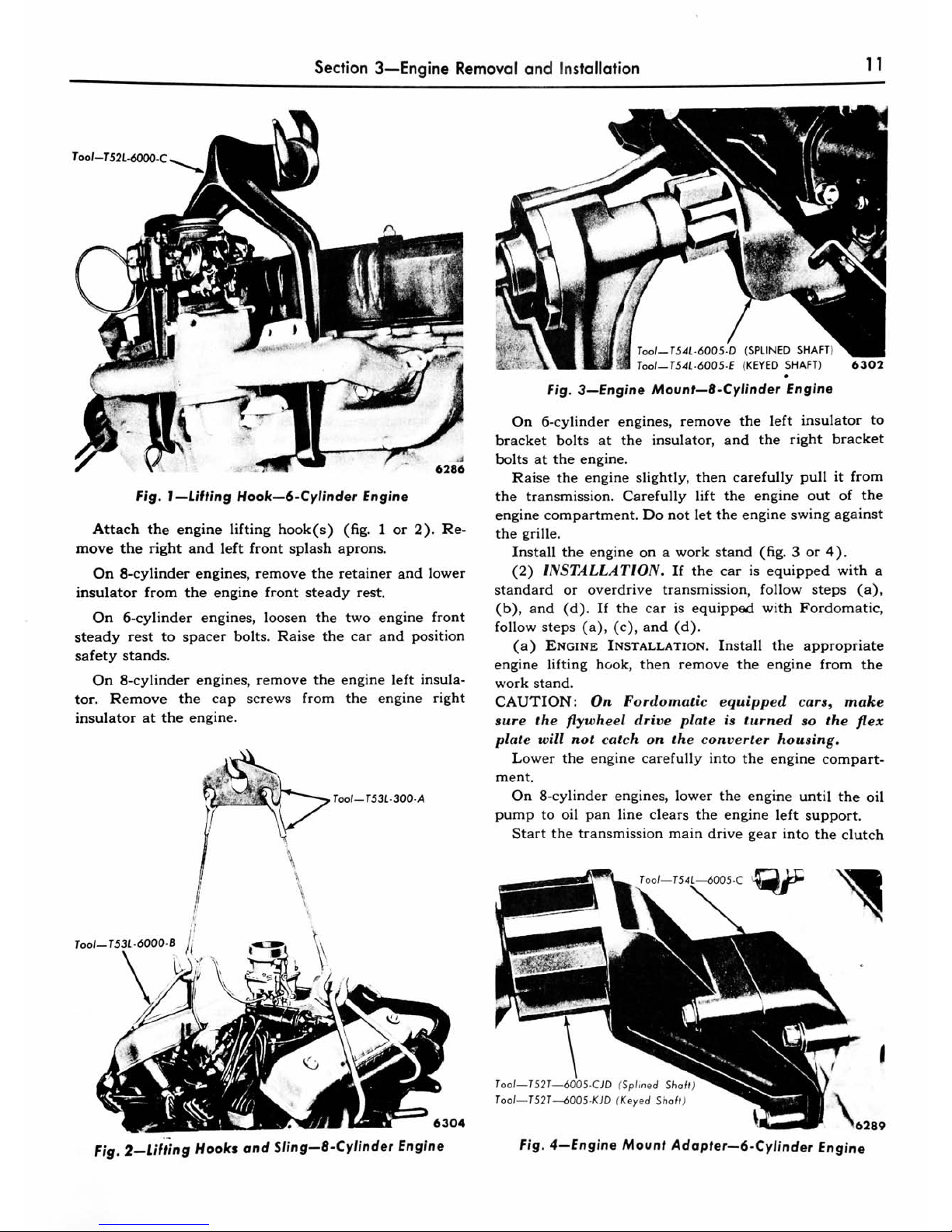
Too/-T52L-6000-C
Fig.
J
Lifting
Hook
6-Cylinder
Engine
Attach
the
engine
lifting
hook(s)
(fig.
1or2).
Re
move
the
right
and
left
front
splash
aprons.
On
8-cylinder
engines,
remove
the
retainer
and
lower
insulator
from
the
engine
front
steady
rest.
On
6-cylinder
engines,
loosen
the
two
engine
front
steady
rest
to
spacer
bolts.
Raise
the
car
and
position
safety
stands.
On
8-cylinder
engines,
remove
the
engine
left
insula
tor.
Remove
the
cap
screws
from
the
engine
right
insulator
at
the
engine.
Tool-T53L-300-A
ToolT53L-6000-B
Tool-
1
5
41-600
5-D
(SPLINED
SHAFT)
Tool
T54L-6005-E
(KEYED
SHAFT)
6302
Fig.
3
Engine
Mount
8
-Cylinder
Engine
On
6-cylinder
engines,
remove
the
left
insulator
to
bracket
bolts
at
the
insulator,
and
the
right
bracket
bolts
at
the
engine.
Raise
the
engine
slightly,
then
carefully
pull
it
from
the
transmission.
Carefully
lift
the
engine
out
of
the
engine
compartment.
Do
not
let
the
engine
swing
against
the
grille.
Install
the
engine
on
a
work
stand
(fig.
3
or
4).
(2)
INSTALLATION.
If
the
car
is
equipped
with
a
standard
or
overdrive
transmission,
follow
steps
(a),
(b),
and
(d).
If
the
car
is
equipped
with
Fordomatic,
follow
steps
(a),
(c),
and
(d).
(a)
Engine
Installation.
Install
the
appropriate
engine
lifting
hook,
then
remove
the
engine
from
the
work
stand.
CAUTION:
On
Fordomatic
equipped
cars,
make
sure
the
flywheel
drive
plate
is
turned
so
the
flex
plate
will
not
catch
on
the
converter
housing.
Lower
the
engine
carefully
into
the
engine
compart
ment.
On
8-cylinder
engines,
lower
the
engine
until
the
oil
pump
to
oil
pan
line
clears
the
engine
left
support.
Start
the
transmission
main
drive
gear
into
the
clutch
6304
ToolT52T6005-CJD
(Splined
Sha
ToolT52T-^>005-KJD
(Keyed
Shaft)
6289
Fig.
2
Lifting
Hooks
and
Sling
8-Cylinder
Engine
Fig.
4
Engine
Mount
Adapter
6-Cylinder
Engine
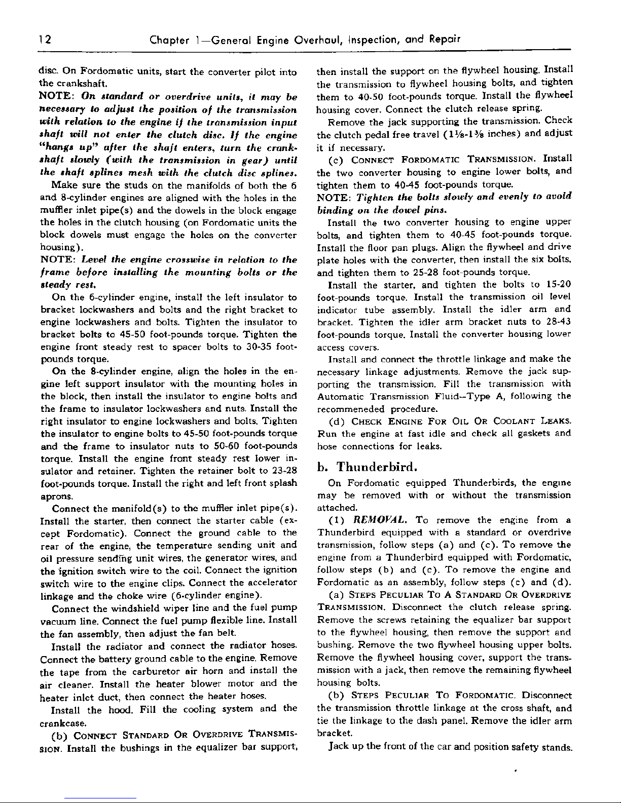
12
Chapter
1
General
Engine
Overhaul,
Inspection,
and
Repair
disc.
On
Fordomatic
units,
start
the
converter
pilot
into
the
crankshaft.
NOTE:
On
standard
or
overdrive
units,
it
may
be
necessary
to
adjust
the
position
of
the
transmission
with
relation
to
the
engine
if
the
transmission
input
shaft
will
not
enter
the
clutch
disc.
If
the
engine
"hangs
up"
after
the
shaft
enters,
turn
the
crank
shaft
slowly
(with
the
transmission
in
gear)
until
the
shaft
splines
mesh
with
the
clutch
disc
splines.
Make
sure
the
studs
on
the
manifolds
of
both
the
6
and
8-cylinder
engines
are
aligned
with
the
holes
in
the
muffler
inlet
pipe(s)
and
the
dowels
in
the
block
engage
the
holes
in
the
clutch
housing
(on
Fordomatic
units
the
block
dowels
must
engage
the
holes
on
the
converter
housing).
NOTE:
Level
the
engine
crosswise
in
relation
to
the
frame
before
installing
the
mounting
bolts
or
the
steady
rest.
On
the
6-cylinder
engine,
install
the
left
insulator
to
bracket
lockwashers
and
bolts
and
the
right
bracket
to
engine
lockwashers
and
bolts.
Tighten
the
insulator
to
bracket
bolts
to
45-50 foot-pounds
torque.
Tighten
the
engine
front
steady
rest
to
spacer
bolts
to
30-35
foot
pounds
torque.
On
the
8-cylinder
engine,
align
the
holes
in
the
en
gine
left
support
insulator
with
the
mounting
holes
in
the
block,
then
install
the
insulator
to
engine
bolts
and
the
frame
to
insulator
lockwashers
and
nuts.
Install
the
right
insulator
to
engine
lockwashers
and
bolts.
Tighten
the
insulator
to
engine
bolts
to
45-50
foot-pounds
torque
and
the
frame
to
insulator
nuts
to
50-60
foot-pounds
torque.
Install
the
engine
front
steady
rest
lower
in
sulator
and
retainer.
Tighten
the
retainer
bolt
to
23-28
foot-pounds
torque.
Install
the
right
and
left
front
splash
aprons.
Connect
the
manifold
(s)
to
the
muffler
inlet
pipe(s).
Install
the
starter,
then
connect
the
starter
cable
(ex
cept
Fordomatic).
Connect
the
ground
cable
to
the
rear
of
the
engine,
the
temperature
sending
unit
and
oil
pressure
sending
unit
wires,
the
generator
wires,
and
the
ignition
switch
wire
to
the
coil.
Connect
the
ignition
switch
wire
to
the
engine
clips.
Connect
the
accelerator
linkage
and
the
choke
wire
(6-cylinder
engine).
Connect
the
windshield
wiper
line
and
the
fuel
pump
vacuum
line.
Connect
the
fuel
pump
flexible
line.
Install
the
fan
assembly,
then
adjust
the
fan
belt.
Install
the
radiator
and
connect
the
radiator
hoses.
Connect
the
battery
ground
cable
to
the
engine.
Remove
the
tape
from
the
carburetor
air
horn
and
install
the
air
cleaner.
Install
the
heater
blower
motor
and
the
heater
inlet
duct,
then
connect
the
heater
hoses.
Install
the
hood.
Fill
the
cooling
system
and
the
crankcase.
(b)
Connect
Standard
Or
Overdrive
Transmis
sion.
Install
the
bushings
in
the
equalizer
bar
support,
then
install
the
support
on
the
flywheel
housing.
Install
the
transmission
to
flywheel
housing
bolts,
and
tighten
them
to
40-50
foot-pounds
torque.
Install
the
flywheel
housing
cover.
Connect
the
clutch
release
spring.
Remove
the
jack
supporting
the
transmission.
Check
the
clutch
pedal
free
travel
(lH-l3/8
inches)
and
adjust
it
if
necessary.
(c)
Connect
Fordomatic
Transmission.
Install
the
two
converter
housing
to
engine
lower
bolts,
and
tighten
them
to
40-45
foot-pounds
torque.
NOTE:
Tighten
the
bolts
slowly
and
evenly
to
avoid
binding
on
the
dowel
pins.
Install
the
two
converter
housing
to
engine
upper
bolts,
and
tighten
them
to
40-45
foot-pounds
torque.
Install
the
floor
pan
plugs.
Align
the
flywheel
and
drive
plate
holes
with
the
converter,
then
install
the
six
bolts,
and
tighten
them
to
25-28
foot-pounds
torque.
Install
the
starter,
and
tighten
the
bolts
to
15-20
foot-pounds
torque.
Install
the
transmission
oil
level
indicator
tube
assembly.
Install
the
idler
arm
and
bracket.
Tighten
the
idler
arm
bracket
nuts
to
28-43
foot-pounds
torque.
Install
the
converter
housing
lower
access
covers.
Install
and
connect
the
throttle
linkage
and
make
the
necessary
linkage
adjustments.
Remove
the
jack
sup
porting
the
transmission.
Fill
the
transmission
with
Automatic
Transmission
Fluid
Type
A,
following
the
recommeneded
procedure.
(d)
Check
Engine
For
Oil
Or
Coolant
Leaks.
Run
the
engine
at
fast idle
and
check
all
gaskets
and
hose
connections
for leaks.
b.
Thunderbird.
On
Fordomatic
equipped
Thunderbirds,
the
engine
may
be
removed
with
or
without
the
transmission
attached.
(1)
REMOVAL.
To
remove
the
engine
from
a
Thunderbird
equipped
with
a
standard
or
overdrive
transmission,
follow
steps
(a)
and
(c).
To
remove
the
engine
from
a
Thunderbird
equipped
with
Fordomatic,
follow
steps
(b)
and
(c).
To
remove
the
engine
and
Fordomatic
as
an
assembly,
follow
steps
(c)
and
(d).
(a)
Steps
Peculiar
To
A
Standard
Or
Overdrive
Transmission.
Disconnect
the
clutch
release
spring.
Remove
the
screws
retaining
the
equalizer
bar
support
to
the
flywheel
housing,
then
remove
the
support
and
bushing.
Remove
the
two
flywheel
housing
upper
bolts.
Remove
the
flywheel
housing
cover,
support
the
trans
mission
with
a
jack,
then
remove
the
remaining
flywheel
housing
bolts.
(b)
Steps
Peculiar
To
Fordomatic.
Disconnect
the
transmission
throttle
linkage
at
the
cross
shaft,
and
tie
the
linkage
to
the
dash
panel.
Remove
the
idler
arm
bracket.
Jack
up
the
front
of
the
car
and
position
safety
stands.
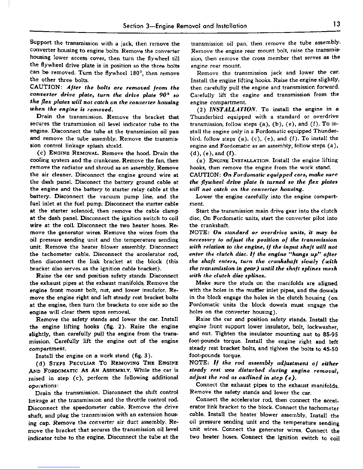
Section
3
Engine
Removal
and
Installation
13
Support
the
transmission
with
a
jack,
then
remove
the
converter
housing
to
engine
bolts.
Remove
the
converter
housing
lower
access
cover,
then
turn
the
flywheel
till
the
flywheel
drive
plate
is
in
position
so
the
three
bolts
can
be
removed.
Turn
the
flywheel
180,
then
remove
the
other
three
bolts.
CAUTION:
After
the
bolts
are
removed
from
the
converter
drive
plate,
turn
the
drive
plate
90
so
the
flex
plates
will
not
catch
on
the
converter
housing
when
the
engine
is
removed.
Drain
the
transmission.
Remove
the
bracket
that
secures
the
transmission
oil
level
indicator
tube
to
the
engine.
Disconnect
the
tube
at
the
transmission
oil
pan
and
remove
the
tube
assembly.
Remove
the
transmis
sion
control
linkage
splash
shield.
(c)
Engine
Removal.
Remove
the
hood.
Drain
the
cooling
system
and
the
crankcase.
Remove
the
fan,
then
remove
the
radiator
and
shroud
as
an
assembly.
Remove
the
air
cleaner.
Disconnect
the
engine
ground
wire
at
the
dash
panel.
Disconect
the
battery
ground
cable
at
the
engine
and
the
battery
to
starter
relay
cable
at
the
battery.
Disconnect
the
vacuum
pump
line,
and
the
fuel
inlet
at
the
fuel
pump.
Disconnect
the
starter
cable
at
the
starter
solenoid,
then
remove
the
cable
clamp
at
the
dash
panel.
Disconnect
the
ignition
switch
to
coil
wire
at
the
coil.
Disconnect
the
two
heater
hoses.
Re
move
the
generator
wires.
Remove
the
wires
from
the
oil
pressure
sending
unit
and
the
temperature
sending
unit.
Remove
the
heater
blower
assembly.
Disconnect
the
tachometer
cable.
Disconnect
the
accelerator
rod,
then
disconnect
the
link
bracket
at
the
block
(this
bracket
also
serves
as
the
ignition
cable
bracket).
Raise
the
car
and
position
safety
stands.
Disconnect
the
exhaust
pipes
at
the
exhaust
manifolds.
Remove
the
engine
front
mount
bolt,
nut,
and
lower
insulator.
Re
move
the
engine
right
and
left
steady
rest
bracket
bolts
at
the
engine,
then
turn
the
brackets
to
one
side
so
the
engine
will
clear
them
upon
removal.
Remove
the
safety
stands
and
lower
the
car.
Install
the
engine
lifting
hooks
(fig.
2).
Raise
the
engine
slightly,
then
carefully
pull
the
engine
from
the
trans
mission.
Carefully
lift
the
engine
out
of
the
engine
compartment.
Install
the
engine
on
a
work
stand
(fig.
3).
(d)
Steps
Peculiar
To
Removing
The
Engine
And
Fordomatic
As
An
Assembly.
While
the
car
is
raised
in
step
(c),
perform
the
following
additional
operations
:
Drain
the
transmission.
Disconnect
the
shift
control
linkage
at
the
transmission
and
the
throttle
control
rod.
Disconnect
the
speedometer
cable.
Remove
the
drive
shaft,
and
plug
the
transmission
with
an
extension
hous
ing
cap.
Remove
the
converter
air
duct
assembly.
Re
move
the
bracket
that
secures
the
transmission
oil
level
indicator
tube
to
the
engine.
Disconnect
the
tube
at
the
transmission
oil
pan,
then
remove
the
tube
assembly.
Remove
the
engine
rear
mount
bolt,
raise
the
transmis
sion,
then
remove
the
cross
member
that
serves
as
the
engine
rear
mount.
Remove
the
transmission
jack
and
lower
the
car.
Install
the
engine
lifting
hooks.
Raise
the
engine
slightly,
then
carefully
pull
the
engine
and
transmission
forward.
Carefully
lift
the
engine
and
transmission
from
the
engine
compartment.
(2)
INSTALLATION.
To
install
the
engine
in
a
Thunderbird
equipped
with
a
standard
or
overdrive
transmission,
follow
steps
(a),
(b),
(e),
and
(f).
To
in
stall
the
engine
only
in
a
Fordomatic
equipped
Thunder
bird,
follow
steps
(a),
(c),
(e),
and
(f).
To
install
the
engine
and
Fordomatic
as
an
assembly,
follow
steps
(a),
(d),(e),and(f).
(a)
Engine
Installation.
Install
the
engine
lifting
hooks,
then
remove
the
engine
from
the
work
stand.
CAUTION
:
On
Fordomatic
equipped
cars,
make
sure
the
flywheel
drive
plate
is
turned
so
the
flex
plates
will
not
catch
on
the
converter
housing.
Lower
the
engine
carefully
into
the
engine
compart
ment.
Start
the
transmission
main
drive
gear
into
the
clutch
disc.
On
Fordomatic
units,
start
the
converter
pilot
into
the
crankshaft.
NOTE:
On
standard
or
overdrive
units,
it
may
be
necessary
to
adjust
the
position
of
the
transmission
with
relation
to
the
engine,
if
the
input
shaft
will
not
enter
the
clutch
disc.
If
the
engine
"hangs
up"
after
the
shaft
enters,
turn
the
crankshaft
slowly
(with
the
transmission
in
gear)
until
the
shaft
splines
mesh
with
the
clutch
disc
splines.
Make
sure
the
studs
on
the
manifolds
are
aligned
with
the
holes
in
the
muffler
inlet
pipes,
and
the
dowels
in
the
block
engage
the
holes
in
the
clutch
housing
(on
Fordomatic
units
the
block
dowels
must
engage
the
holes
on
the
converter
housing).
Raise
the
car
and
position
safety
stands.
Install
the
engine
front
support
lower
insulator,
bolt,
lockwasher,
and
nut.
Tighten
the
insulator
mounting
nut
to
85-95
foot-pounds
torque.
Install
the
engine
right
and
left
steady
rest
bracket
bolts,
and
tighten
the
bolts
to
45-50
foot-pounds
torque.
NOTE:
If
the
rod
assembly
adjustment
of
either
steady
rest
was
disturbed
during
engine
removal,
adjust
the
rod
as
outlined
in
step
(e).
Connect
the
exhaust
pipes
to the
exhaust
manifolds.
Remove
the
safety
stands
and
lower
the
car.
Connect
the
accelerator
rod,
then
connect
the
accel
erator
link
bracket
to
the
block.
Connect
the
tachometer
cable.
Install
the
heater
blower
assembly.
Install
the
oil
pressure
sending
unit
and
the
temperature
sending
unit
wires.
Connect
the
generator
wires.
Connect
the
two
heater
hoses.
Connect
the
ignition
switch
to
coil
 Loading...