

Page 1
Page 2
www.carburetor-manual.com
Would you like some Free Manuals?
http://carburetor-manual.com/free-shop-manual-club-t-13.html
Also visit http://freeshopmanual.com for more Free Manuals
Also Visit my website for 7 FREE Download Manuals starting
with this one.
"The ABC's of Carburetion"
Click Here Now
file:///C|/Documents%20and%20Settings/Tim/Desktop/carburetor-manual-welcome/index.htm[4/25/2009 11:42:20 AM]
Page 3
-
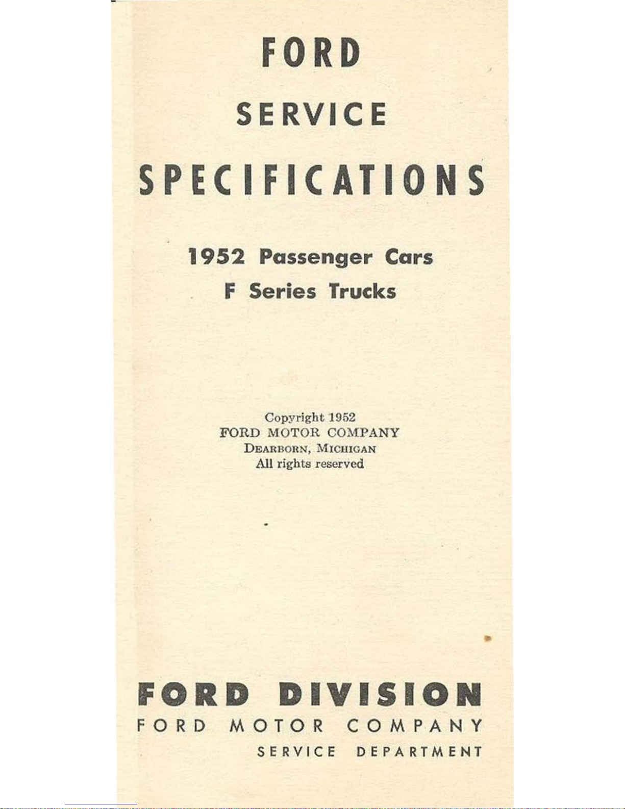
FORD
SERVICE
,
SPECIFICATIO S
1952
Passenger Cars
F Series Trucks
Copyrigbt
1952
FORD
MOTOR COMPANY
DEARnon~
.
MI
CUlCAN
All rights reserved
•
D
DIYISIO
FORD
MOTOR
COMPANY
S E RV I
CE
DEPARTMEN
T
,
Page 4
•
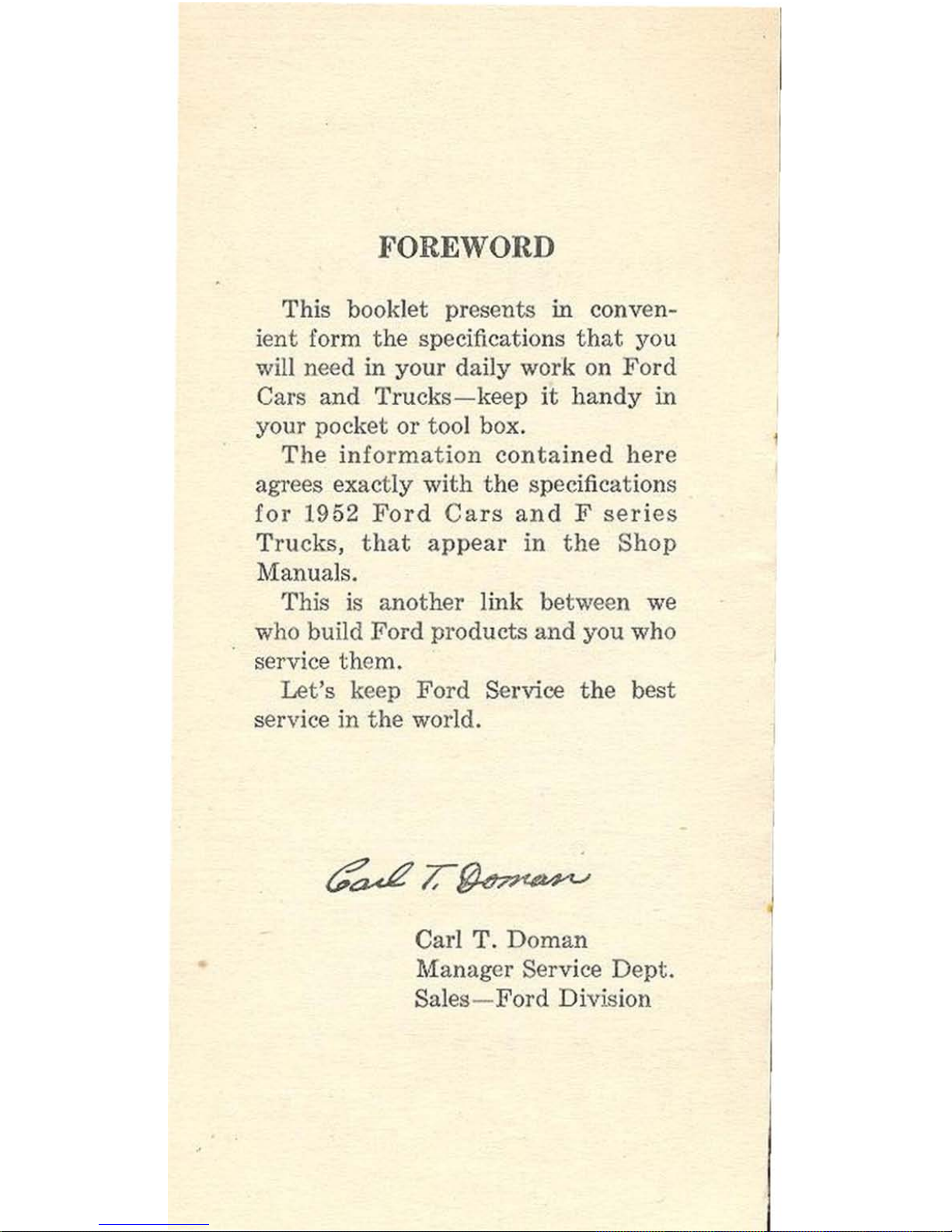
FOREWORD
This booklet presents in conven-
ient form
the
specifications
that
you
will need in your daily work on Ford
Cars and
Trucks-keep
it
handy
in
your pocket or tool box.
The
information
contained
here
agrees exactly with
the
specifications
for
1952
Ford
Ca
rs
and
F
series
Trucks,
that
appea
r in
the
Shop
Manuals.
This is another link between
we
who build
Ford
products
and
you who
service them.
Let's
keep
Ford
Service
the
best
service in
the
world.
Carl T.
Doman
Manager Serv i
ce
Dept
.
Sales-
Ford
Division
Page 5
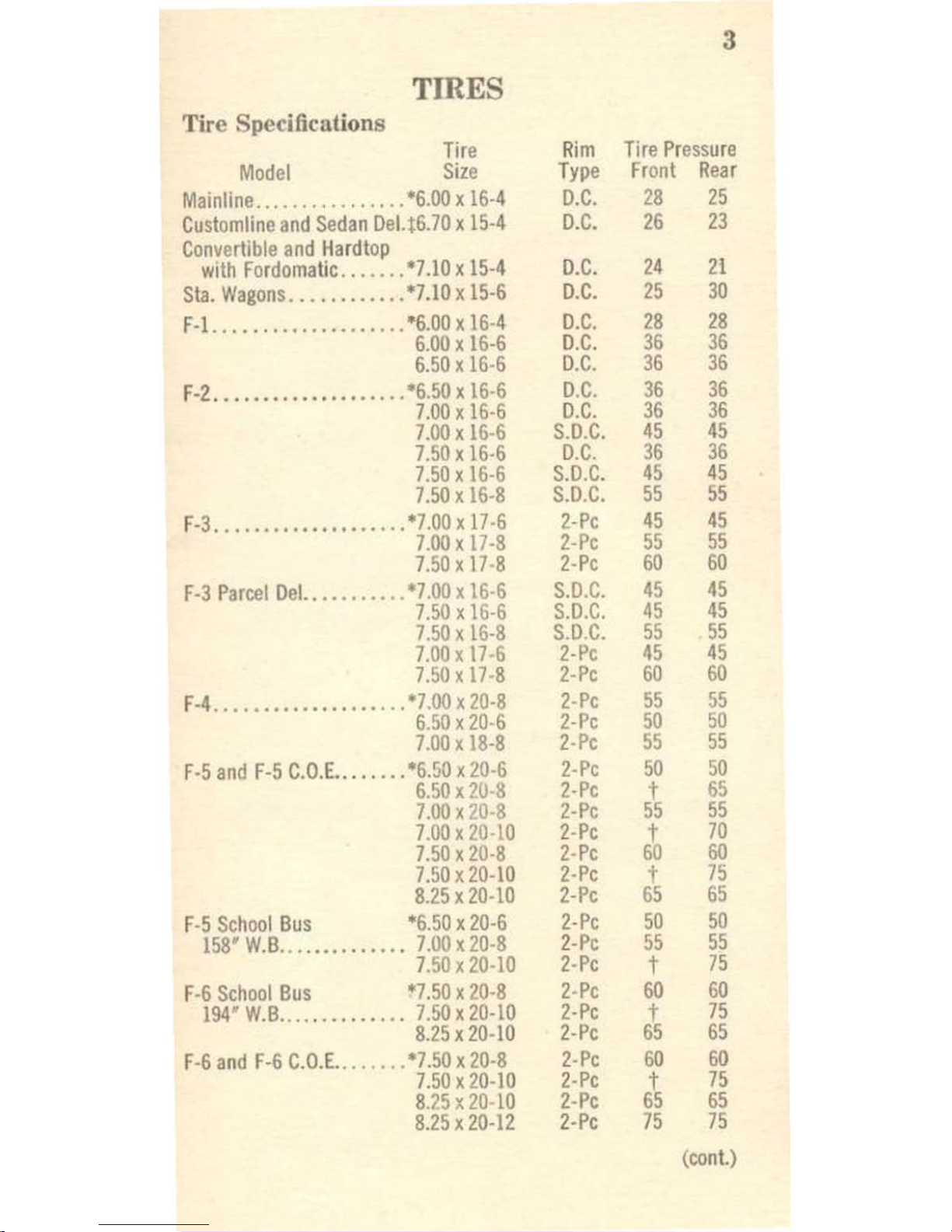
3
TffiES
Tire Specifications
Tire
R
im
Tire
Pressure
Model
Size
Type
Front
Rear
Mainline
................
*6.00 x 16·4
D
.C.
28
25
Customline
and
Sedan
DeLt6.70 x 15·4
D.C.
26
23
Convertible
and
Hardtop
with
Fordoma
tie
.......
*7.10 x 15·4
D.C.
24
21
Sta.
Wagons
............
'7.10 x
15·6
D.C.
25
30
F·l.
...................
*6.00 x 16
·4
D.C.
28
28
6.00 x 16·6
D
.C.
36 36
6.50 x 16
·6
D.C.
36
36
F-Z .........
.......
....
*6.50 x 16·6
D.C.
36 36
7.00xI6-6
D
.C.
36
36
7.00
xl6·6
S.D.C.
45
45
7.50 x 16
·6
D.C.
36
36
7.50xI6·6
S.D.C.
45 45
7.50 x 16·8
S.D.C.
55
55
F-3
....
...
.....
........
·7.00x
17·6
Z·Pe
45 45
7.00 x 17·8
2-Pe
55
55
7.50 x 17
-8
2·Pe
60
60
F-3
Parcel
Del.
..........
*7.00 x 16-6
S.D.C.
45
45
7.50 x 16-6
S.D.C.
45
45
7.50x
16-8
S.D
.C.
55
55
7
.00 x 17
-6
2-Pe
45
45
7.
50 x 17-8
2-Pe
60
60
F-4
....................
'7.00 x
20-8
2·Pe
55 55
6
.50 x 20·6
2-Pe
50
50
7.00 x 18-8
2·Pe
55
55
F·5
and
F-5
C.O.E
•..
...
..
*6.50 x 20-6
2·Pe
50
50
6.50 x 20-8
2-Pe
t
65
7.00 x 20-8
2-Pe
55
55
7.00 x 20·10
Z·Pe
6~
70
7.50 x 20·8
2·
Pe
60
7.50x20-10
2·Pe
t
75
8.25 x 20-10
Z-Pe
65 65
F·5
School
Bus
*6.50 x 20·6
2·Pe
50
50
158'
W.B
..............
7.00x20·8
2-Pe
55
55
7.50 x 20-10
2·Pe
t
75
F-6
School
Bus
'7
.50 x 20-8
2-Pe
60
60
194'
W.B
.......
.....
..
7.50 x 20-10
2
·Pe
t
75
8.25 x 20·10
2·Pe
65
65
F-6
and
F-6
C.O.E ........
*7.50 x 20·8
2·Pe
60
60
7
.50
x20-10
2-Pe
t
75
8.25 x 20·10
2·Pe
65 65
8.25 x 20-12
2·Pe
75 75
(eon
t.)
Page 6
4
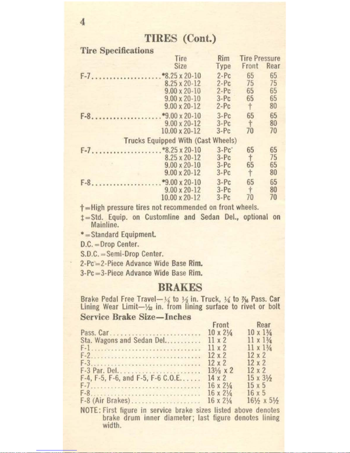
TffiES (Cont.)
Tire Specifications
Tire
Size
Rim
Tire
Pressure
Type
Front
Rear
F-7
....................
·S.25, 20-
10
S.25,20-
12
9.00,20-
to
9.00,20-
10
9.00,20-12
2-Pe
65 65
2-Pe
75
75
2-Pe
65
65
3-Pe
65
65
2-Pe
t
SO
F-S
•...•.•.............
'9.00, 20-
10
9.00,20-12
10.00 x 20·12
3-Pe
65
65
3-Pe
t
SO
3-Pe
70 70
Trucks
Equipped
With
(Cast
Wheels
)
F-7
...................
. *8.25,
20-10
3-Pe
'
8.25,20-12
3-Pe
9.00,20-
10
3-Pe
9.00,20-
12
3-Pe
F-S
...............
.....
'9.00, 20·
to
3-Pe
9.00,20-
12
3-Pe
10.00,20-12
3-
Pc
65
t
65
t
65
7b
65
75
65
80
65
SO
70
t=High
pressure
tires
not
recommended
on
front
wheels.
t =
Std_
Equip.
on
Customline
and
Sedan
Del..
optional
on
Mainline
.
• -
Standard
Equipmenl
D.C
. -
Drop
Center.
S.D.C. -Semi-Drop
Center.
2-
Pe
....
2-Pieee
Advance
Wide
Base
Rim.
3-Pe -3-Pieee
Advance
Wide
Base
Rim.
BRAKES
Brake
Pedal
Free
Travel-X
to
~
in.
Truck. X to
%6
Pass.
Car
Lining
Wear
Limit-Y.., in.
from
lining
surface
to
rivet
or
bolt
Service Brake
Size-Inches
Front
Rear
Pa
ss.
Car
...
.. ..
_....
........
.. .. ..
10,2\4
10,
1 %
Sta.
Wagons
and
Sedan
Del..
.........
11,2
11
,
1%
F-l
..................
..
........
..
..
11,2
11,1%
F -2..
.. .. .. .. .. .. .. .. ..
..
..
.. ..
.. ..
12,
2
12
, 2
F
·3.,.....
..
..
....
.. ..
..
.....
......
12,
2
12
, 2
F-3
Par.
Del
........
_....
....
. ..
....
13~,
2
12
, 2
F·
4. F-5, F-6.
and
F-5,
F-6 C.O.E.
. . . ..
14,
2
15
,
3~
F·7
........... _ .. _ .................
16,2\4
15,5
F-8
..
.............................
16,2\4
16,
5
F-8 (Air
Brakes
)............
........
16,2\4
16¥.,
,5¥.,
NOTE: Fir
st
figure
in
service
brake
sizes
listed
above
denotes
brake
drum
inner
diameter; last
figure
denotes
lining
width
.
Page 7
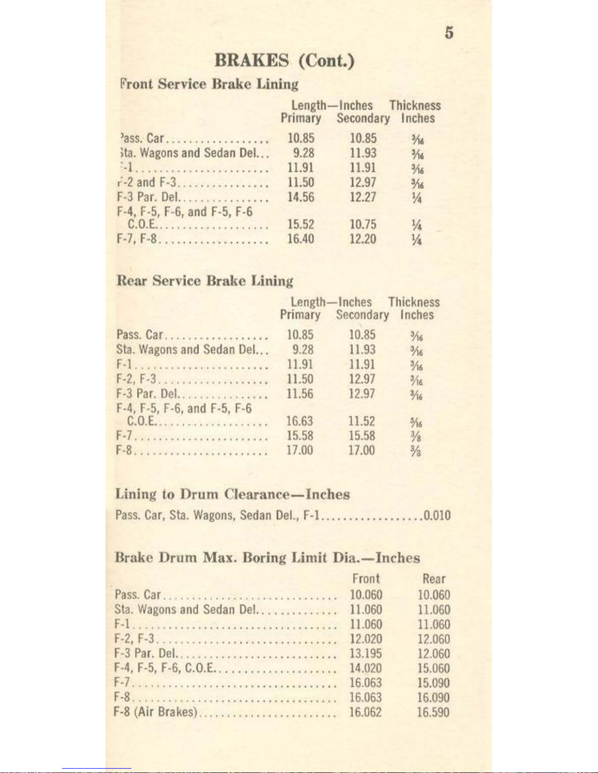
(Cont.)
Front Service Brake Lining
)as-s.
Car
....
.........
.... .
ita. Wagons
and
Sedan
Del.
..
• 1
' .
...............
....... .
,
-2
and
F-3..
............
. .
F-3
Par.
Del.
....
, ,
........
.
F-4 F-S F-6
and
F-S
F-6
I
r,
,
C.
O.E
................
, .. .
F-7.F
-8
.............
.
....
.
Length-Inches
Thickness
Primary
Secondary
Inches
10.85
10.85
M.
9.28
11.93
~.
11.91 11.91
~.
11.50
12.97
~.
14.56
12.27
~
IS.52
16.40
10.75
12.20
Rear Service Brake .Lining
Pas
s.
Car
..............
...
.
Sta. Wagons and
Sedan Del..
.
F-l
...... , ....
, ,
.......
.. .
F-2,F·3
...............
.
..
.
F
-3
Par
. De
l.
.............
"
F-4, F-
5, F-6,
and
F-S,
F-6
C.O.E
...................
.
F -7 . . . . . . . . . . . . • • . • . . . .•••
F -8. . . . . . . . . . • . . . . . . . .
....
Length-Inches
Thickne
ss
Primary
Secondary
Inches
10.85
10.
85 'A.
9.28
11.9
3
~.
11.91
11.91
~
.
11.50 12.97
~.
11.56
12.97
0/1,
16.63
15.58
17.00
11.52
15.58
17.00
Lining to Drum
Clearance-Inches
5
Pass.
Car,
Sta. Wagon
s,
Sedan
Del.,
F-I .. .......
......
...
0.010
Brake Drum Max. Boring Limit
nia.-Inches
Front
Rear
Pa
ss.
Car. . . . . . . . . . . . . . . . . . . . . . . . . . . . . .
10.060
10.06
0
S
ta
. Wagons
and Sedan
Del
.... ...
.......
11.060
11.0
60
F-t .......................
..
...••...
. .
11.060
11
,060
F-2, F-3. . . ..
...
. . . . . .
....
. . .
..
...
. ..
.. 12.02
0 12.060
F
-3
Par.
Del.. . . . . . . . . . . . . . . • .
..
.. . ..
..
. 13
.195
12
.06
0
F-
4, F-5, F·6, C.O.E..
. . . . . .
.........
...
.
14
.02
0
15.060
F-
7.
. . .
.....
... . .....
..
...
. ... .... .... 16.0
63
15
.090
F-B
....... , ... , .........•
_ ..••.....
... 16.063
16.090
F-8 (
Air
Brake
s)..............
..
........
16
.06
2 16.590
Page 8
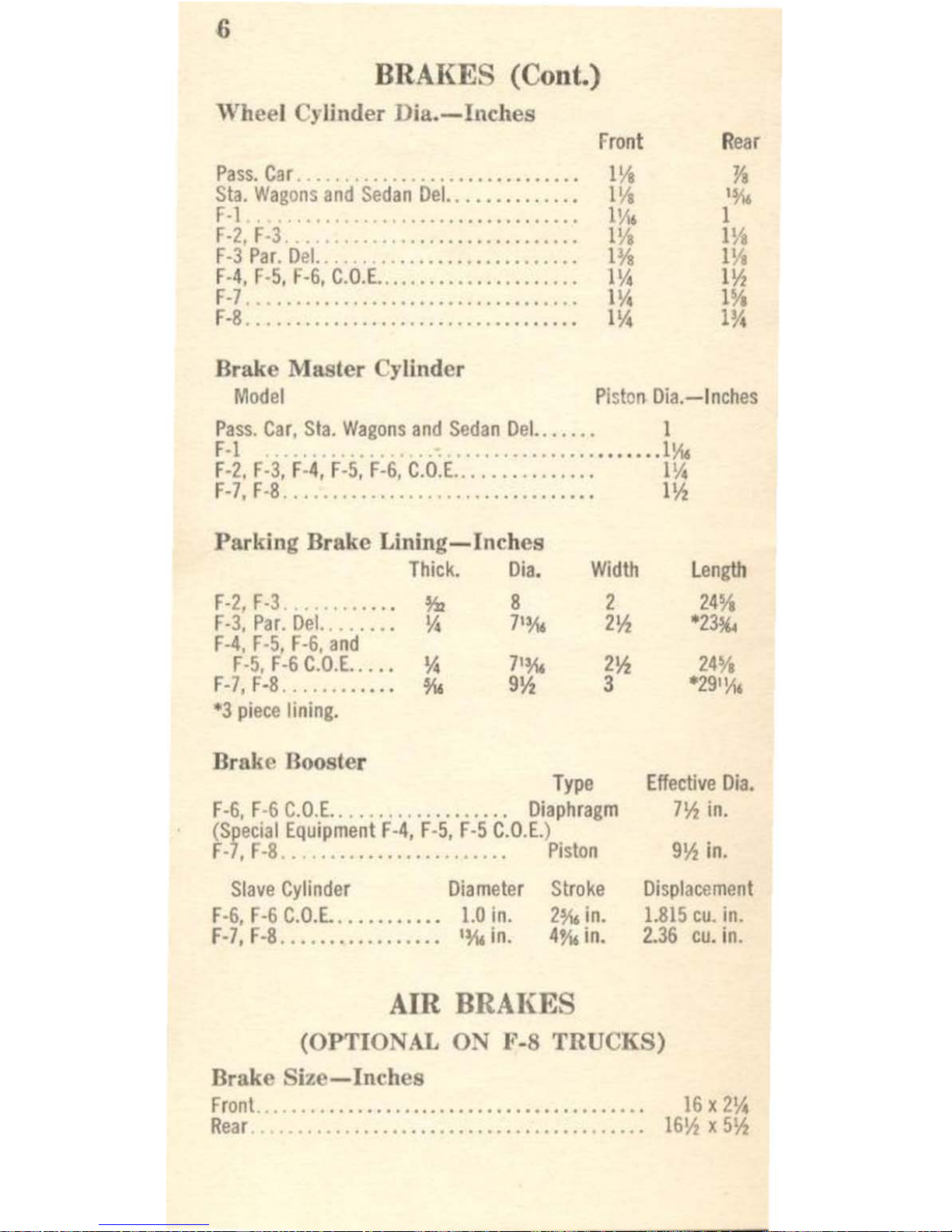
BRAI<:ES
(Cont.)
Wheel Cylinder
Dia.-IncItes
Front
Rear
Pass.
Car
...............
.........
IVa
Ya
Sta.
Wag
ons
and
Sedan
Del.
. . .
......
..
.• I
Va
't\6
r·1 .
.....
....
........
..
1\'\6
I
F·2
, F
·3
...
................
..
IVa
I
V,
F·3
Par. Del.
..
. . ........
......
.....
w.
m
F·
4,
F·5,
F·G,
C.O.E.
....
...
......
..
......
I~
l~
F·7
...
....
...............
........
...
I~
lYo
F·g
..........
......
..
.................
I~
lY.
Brake
Master
Cylinder
Model
Piston
Dia.-Inches
Pass. Car, Sta.
Wagons
and
Sedan
Del.
. . .
...
I
F·I
.
.. . ..............••.
.•..
11'1<
F·2,
F·3,
F·4,
F·5,
F·G,
C.O.E
...
, . ..
....
,...
I~
F·7,
F·g.
..........................
......
I~
Parking Brake
Lining-Inches
Thick.
Dia.
Width
F·2,
F·3
....
...
..
.
*'
g
2
F·3,
Par.
Del.
......
Yo
7'loI.
2~
F·4
, F·
5,
F·G,
and
F·5,
F·G
C.O.E
.....
~
7'loI.
2~
F·7,
F·8..
......
....
t\6
9~
3
"3
piece
lining.
Brake Booster
Type
F·G,
F·6
C.O.E.
....... ,...
......
.
Diaphragm
(Special
Equipment
F·4, F·5,
F·5
C.O.E.)
F·7,
F·g
..
..
.............
....
Piston
Slave
Cylinder
Diameter
Stroke
F·G,
F·G
C.O.E.
..
......
...
1.0
in.
2lo1.
in.
F·7,
F·g, ................
'loI.
in.
4lo1.
in.
length
24%
*23lO.
24
Yo
'29'\,\,
Effective
Dia.
7~
in,
9~
in.
Displacement
1.815
cu.
in.
2.36
cu. in.
Am
BRAJ<:ES
(OPTIO AL
O~
F-8
TRUCKS)
Brake
Size-Inches
Front
Rear
........................................
.
..
. ............................. .
IG
x
2~
IG
~ x 5~
Page 9
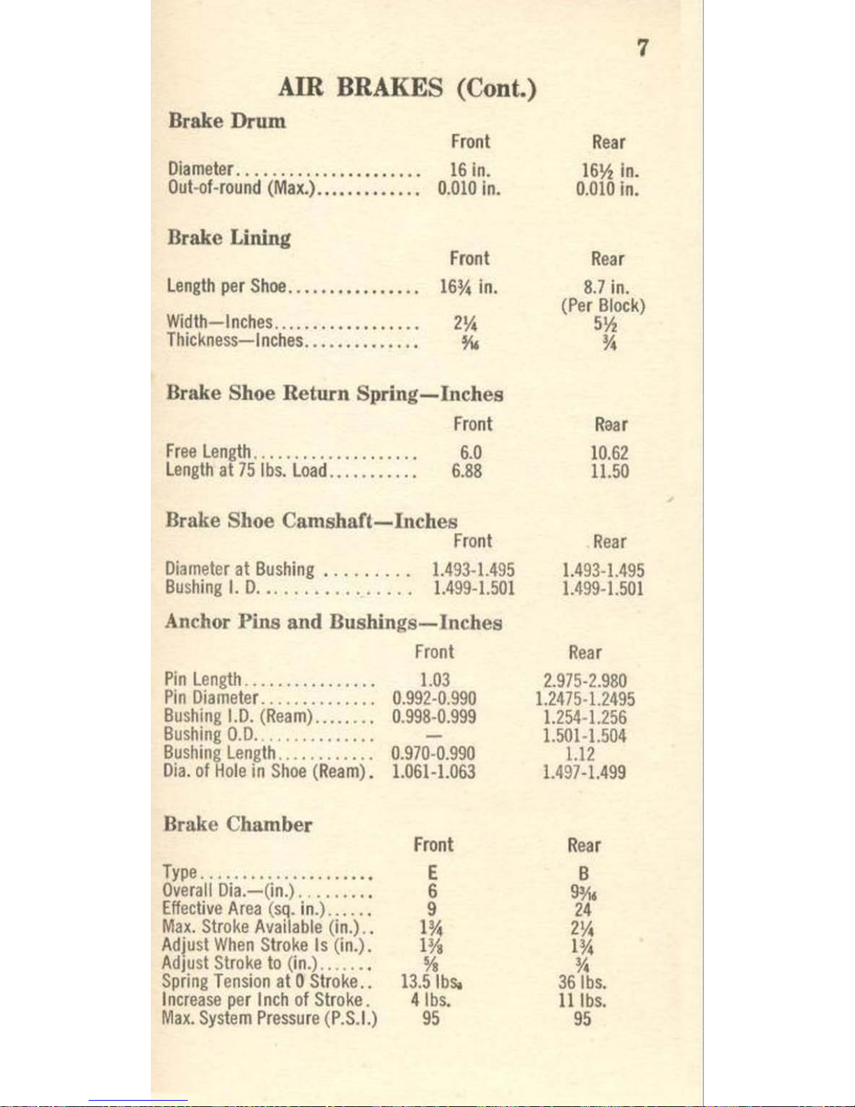
7
Am
BRAKES (Cont.)
Brake Drum
Front
Diameter. . ..
.. . ......
.......
..
16
in.
Out-of-round
(Max.).............
0.010
in.
Brake Lining
Front
length
per
Shoe.
. . . . . . • . . .
••
. . .
16~
in.
Width-Inches..................
2~
Thickness-Inches. . . . . . . . . . . . . .
~
Brake Shoe Return
Spring-Inches
Front
Free
length
...... . .....
. .
......
6.0
len
gth
at
75
Ibs.
load.. . . .
..
. .
..
6.88
Brake Shoe Cams
haft-Inches
Front
~iameter
at Bushing. . . . . . .
..
1.493-1.4
95
Bushing
I.
O. .. . . . . . . . . . . .
..
1.499-1.501
Anchor Pins and
Bushings-Inches
Pin
length
..............
..
Pin
~iameter.
.........
...
.
Bushing
1.0.
(Ream)
......
..
Bushing
0.0 .
..........
..
.
Bushing
length
...........
.
Oia.
of
Hole
in
Shoe (Ream
).
Brake Chamber
Type
. . . .
............
....
.
Overali
Oia.-(in.)
.......
. .
Effective
Area (sq. in.)
.....
.
Max.
Stroke
Available
(in.)
..
Adjust
When Stro
ke
Is
(in.).
Adjust
Stroke
to (
in.) ......
.
Spring
Tension
at 0 Stroke
..
Incr
ease
per
Inch
of
Stroke.
Max.
System
Pressure (P.S.I.
)
Front
1.03
0.992-0.990
0.
998-0.999
-
0.970-0.990
1.061-1.063
Front
E
6
9
1~
l¥.
%
13.5
Ibs.
4
Ibs.
95
Rear
16~
In.
0
.010
in.
Rear
8.7
in.
(Per Block)
5~
~
Roar
10.62
11.50
Rear
1.493-1.495
1.499
-
1.501
Rear
2.
975-2.980
1.2475
·1.249
5
1.254
-1.256
1.501·1.504
1.12
1.497-1.499
Rear
B
9116
24
2Y.
I
~
~
36
Ibs.
II
Ibs.
95
Page 10
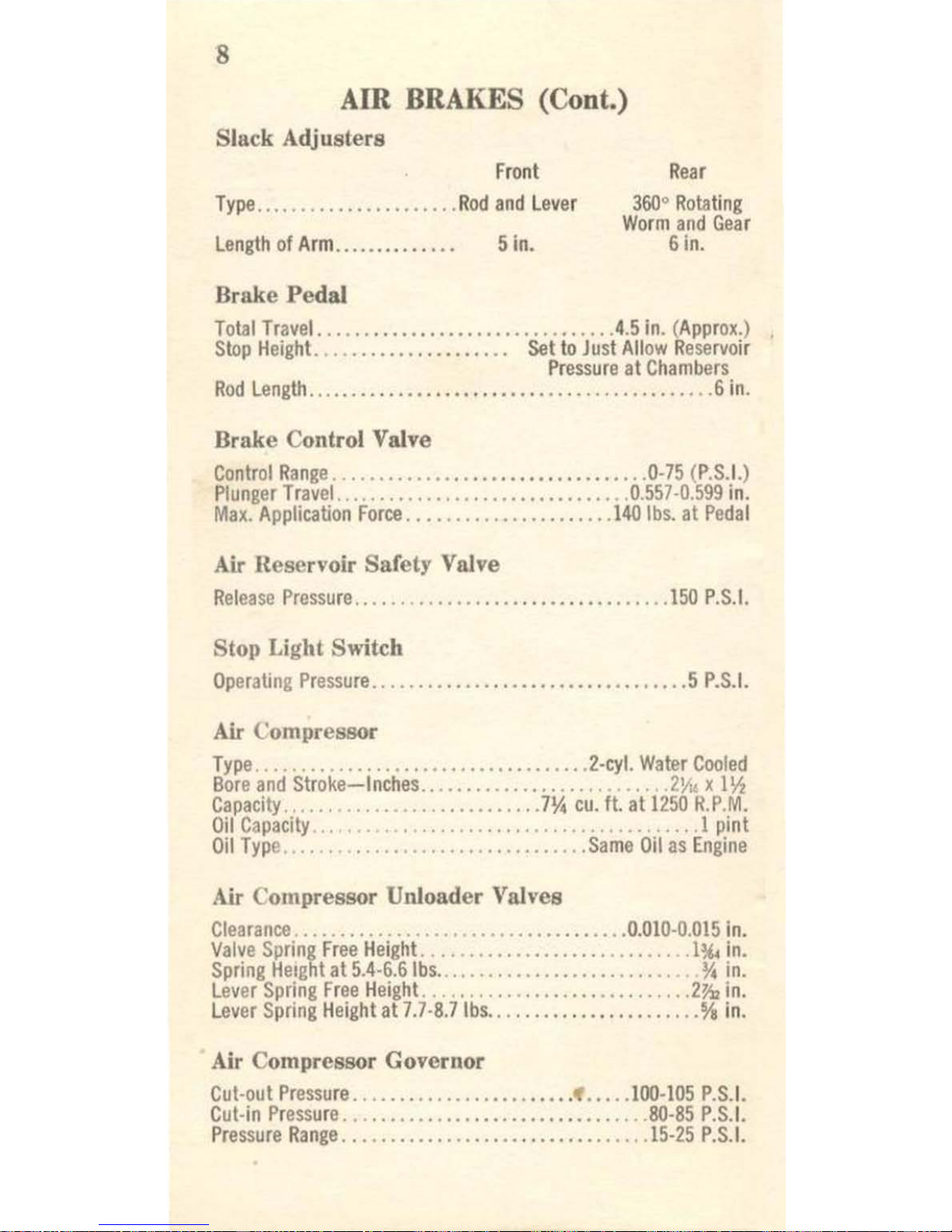
Am
BRAKES (Cont.)
Slack Adjusters
Front
Type
........
.......
.......
Rod
and
Lever
Length
of
Arm..
.....
..
..
..
. 5
in.
Brake
Pedal
Rear
360° Rotating
Worm
and
Gear
6
in.
Total
Travel.
.....
..................
..
...... 4.5
in. (Approx.)
.
Stop
Height.
....
.............
...
Set
to
Just
Allow Rese
rvoir
Pressure
at
Chambers
Rod
Length
........
..
....
................
.......
...
.... 6 in.
Brake Control Valve
Control
Range
......
............................
0·75 (P.S.!.)
Plunger
Travel.
...............................
0.557 ·0.599
in.
Max.
Application
Force .....................
.
140
Ibs.
at
Pedal
Air
Reservoir Safety Valve
Relea
se
Pressure
...............
.
.......
...
........
150
P.S.!.
Stop Light Switch
Op
erating
Pressure
..................................
5
P.S.!.
Air
Compressor
Type
....................................
2-cyl.
Water
Cooled
Bore
and
Stroke-Inches
...........................
2\10
x
I~
Capacity
........................
...
7%
cu.
It.
at
1250
R.P.M.
Oil
Capacity
.",
'"
. , .
............................
1
pint
Oil
Type
...............................
.
Same
Oil
as
Engine
Air
Compressor Unloader Valves
Clearance
. . . . . . . . .
..
. . . . .
.. . ................
0.010
-0.015
in.
Valve
Spring
Free
Height.
......
...
.....
......
........
Il(,
in.
Spring
HeIght
at
S.4-6.6Ibs
............................
%
in.
Lev
er
Spring
Free
Height.
............................
2)1,
in.
Lever
Spring
Height
at
7.7
·8.7
Ibs ....
...................
%
in.
Air Compressor Governor
Cut-out
Pressure
.......................
...
...
100-105 P.S.
!.
Cut-in
Pressure
....
....
...............
...
.......
80-85
P.S.!.
Pressure
Range
......................
..
.........
15-25
P.S.!.
Page 11
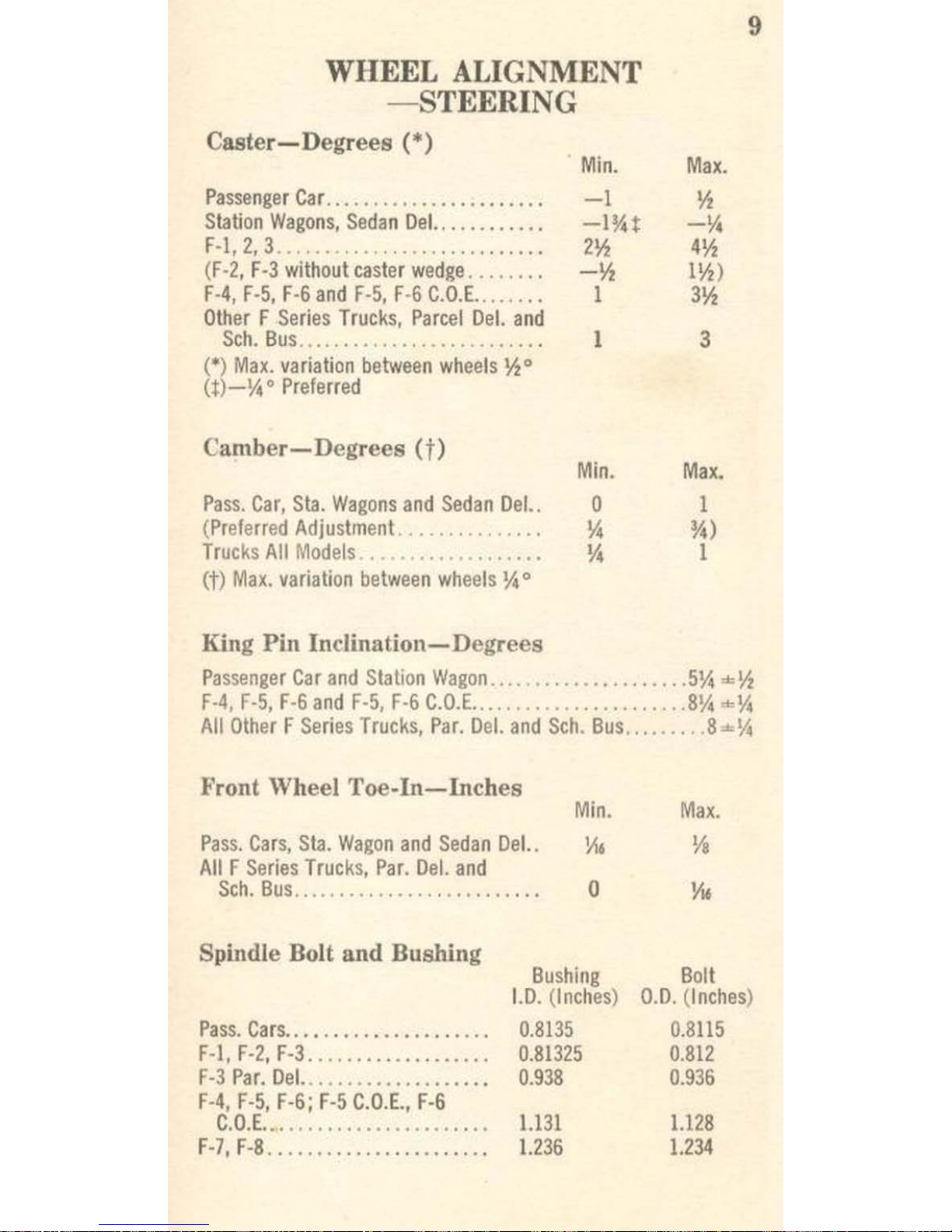
WHEEL
ALIGNMENT
-:STEERING
Caster-Degrees
(*)
Passenger
Car
......................
.
Station
Wagons,
Sedan
Del
.........
'"
F·l,2,3
........
.
..................
.
(F·2, F-3
without
caster
wedge
.......
.
F·4,
F-5,
F-6
and
F-5,
F-6
C.D.E
......
..
Other F Series
Trucks,
Parcel
Del.
and
Sch.
Bus
.....................
. ,
..
.
(0)
Max.
variation
between
wheels
y,o
(.)
_~
0
Preferred
Camber-Degrees
(t)
Pass. Car,
Sta.
Wagons
and
Sedan
Del
..
(Preferred
Adjustment
..............
.
Trucks All
Models.
.•
..
..........
.
..
(t)
Max.
variation
between
wheels
~
0
King Pill
Incliuation-Degrees
Min.
-1
-1%t
2Y,
-y,
1
1
Min.
a
~
~
Max.
y,
-~
4Y,
117)
3Y,
3
Max.
I
m
I
9
Passenger
Car
and
Station
Wagon
.....•...•..
.
........
5~
""y,
F·4, F-S,
F-6
and
F-S, F-6
C.O.E
..... " .....
...
........
8~
=~
All
Other F Series
Trucks,
Par.
Del.
and
Sch. Bus
....
..... 8""\1\
Front Wheel
Toe-In-Inches
Min.
Max.
Pass.
Cars,
Sta.
Wagon
and
Sedan
Del..
All F Series
Trucks,
Par.
Del.
and
Sch.
Bus
..........
.............
.. .
Spiudle Bolt and Bushing
o
Bushing
1.0. (Inches)
Pass.
Cars
.......
.....•...
..
...
F-I,
F·2,
F-3..
................
.
F-3
Par.
Del.
................
..
.
F-4, F·5,
F-6;
F-5
C.O.E.,
F-6
C.O.E
...... .
...
, .
....
......
.. .
F
~7,F-8
. .
........ , ... , .......
.
0.8135
0.81325
0.938
1.131
1.236
Bolt
0.
0. (Inches
)
0.8115
0.812
0.936
1.128
1.234
Page 12

10
WHEEL
ALIGNMENT
-STEERING
(Cont.)
Steering
Gear-Inches
Worm
End
Play
..............
..
Free
Play
at
Steering
Rim-
Straight
Ah
ead
Position
....
,.
Trucks
0.003
(Max.)
1.5
(Max.)
Steering Gear
Adjustments-Pounds
Worm
Bearing
Pre·load
Pull
to
Pa
ss.
Cars
No
Perceptible
No
Perceptible
keep
wheel
moving'
. . . . . . .
..
O·~
Va-%
Steering
Gea
r lash
Adjuslment
Pull
over
center'. .
..........
~-1~
1-1%
"With
steering-linkage
disconnected.
REAR
AXLE
Lubricant
Capacity-P
ints
Pass.
Car,
Sta.
Wagon,
Sedan
Del.
and
F-l.
.........
.
.....
3~
F-2, F-3
, F
-3
Par.
Del
..........
........................
. 3
F·4, F-5,
F-5
C.O.E.
and
Sch.
Bus
........................
5
F·5,
F-6,
F-5
C.O.E.
and
F·6
C.O.E.
(2-s
peed)
......••......
15
F·6,
F-6
C.O.E. (Single
Speed)
...........
................
10
F·7
..............
...................................
..
11
F·7, F·8
(2-s
peed)
..............................
...
....
20
F-8 (Single
Speed)
.........
....
.......
.................
22
Driving Gear and Pinion
Gear
Backlash
(I
nches)
Passenger
Car.
............
..
0.003 0.008
Sta.
Wagon,
Sedan
Del.,
F·l
..
0.003 0.008
F·2,
F·3,
F-3
Par.
Del.
F·4,
F·5
F·5
C.O.E .............
....
0.004 0.018
F·6, F·6
C.O.E ...............
0.004
0.018
F·5,
F·6-Conv.
and C.O.
E.
(2-
sp.)
.................
.. 0.004
oms
F-7
........................
0.006
0.010
F
·S
..........
....
........
0.006 0.010
F-7,
F·S
(2·sp.)
.....
.........
0.006
0.016
'Used
bearing
13-IS
inch-pounds.
Pinion
Bearing
Preload-
(
Inch-Pounds)
22
2S"
S
12
12
16
12
IS
S
15
12
IS
12
25
12
25
Page 13

REAR
AXLE
(Cont.)
Differential
Passen
ger
Car. ...
.............
.
S13.
Wagons,
Sedan
Del.,
F·I.
...
.
F·2,
F-3,
F-3
Par.
Del.
..........
.
F-4,
F-5,
F-5
C.O.E.,
F·5
Sch
.....
.
F·6
(2-spee
d)
.................
.
F-6,
F-6
C.O.E.
(Single
Speed)
...
.
F-7
..........................
.
F-7
(2-speed)
.................
.
F-8
(2-speed)
.........•.•
_
....
.
F-8
(Single
Speed)
.......
.....
.
Shaft (Spider)
Dia
. (I
nches)
0.750
0.7495
0.748
0.871
0.937
0.873
0.996
0.937
0.997
0.937
Differential Side Gear
Thrust
Washers
11
Gears
1.0
. (
Inches)
0.755
0755
0.753
0.878
0.941
0.877
1.004
0
.941
1.002
0.937
Thickness
(
Inches
)
Passenger
Car
..........................
_
........ 0.046-0.048
Sta.
Wagons,
Sedan
Del.,
F-I
......•.........•.....
0.030
-0.032
F-2,
F-3
.....................
..
.................
0.060-0.0S2
F-4,
F-5
........
..................
..
............
0.058·0.0S2
F-S
(2-speed)
...................................
0.OSI-0.OS3
F
-S (Single Speed)
.............•................
0
.058-0.0S2
F-7
....................
..
......................
0
.058-0.0S2
F-7
(2-speed)
......
.............................
0.OSI-0.OS5
F-8
(2-speed)
.....
... _ ••...••..•....
............
0.OSI-0.OS3
F-8 (Single
Speed)
.... _ ......•......
..
...
....... 0.121-0.125
Differential Pinion Gear
Thrust
Washers
Thickness
(Inches)
Passenger
Car.
. . . .
..
. .
........................
0.045·0.049
Sta.
Wagons,
Sedan
Del.,
F-I
......................
0.030-0.032
F-2,
F-3
..........................
..
............
0.061-00S3
F-4,
F-5,
F-S
.................................
... 0.058-0.0S2
F-S
(2-speed)
..................................
0.030-0.032
F-7
...............
'"
...........................
0.058-0.0S2
F-8
(2-speed)
F-7
(2-speed)
.......................
0.030-0.032
F-8
(Single
Speed)
.............................
0.OSI·0.OS3
Page 14

12
FRAMES
,.
·
•
a::(
(
·
•
·
o
e
. .
·
~
:lP
·
·
•
•
G
(.,D>
1-1·
---8
.\
u
•
•
•
•
•
•
•
•
,
..
•
co
..,
'It
..
I
Page 15

A B
C
D E
F
G
Width
Width
~
to ~ Rea
r
~
to ~ Fr
ont
Front
End
Front
Axle
Rear
Axle
Spring Spring
Front
Rear
Dip
Kick-Up
Kick-Up
Hangers Hangers
F-l
32
34
44
35~
2%
- 2
F-2
32
34
45
35~
2%
-
2
F-3
32
34
45
35~
2%
-
2
F-
3 Pa
r.
Del.
32
34
45
35)1,
2%
2
3%
F-4
32
34
44Yz
35Yz
2",1,
- -
00
F-5
32
34
44
Yz
3517
2'l'u
- -
r-.
F-5
C.O
.E.
32
34
44\1
37%
2'l'u
("')
- -
0
F-5
and
F-G
School
Bus
32
34
51lt.
35Yz
2'l'u
-
-
::I
...
•
F-G
32
34
44Yz
35Yz
2'l'u
'-'
-
-
F-6
C.O.E.
32
34
44\1
37%
2'l'u
-
-
F
-7
32
34
51%
45'A.
4 -
-
F-8 32
34
51l/4
4~.
4
-
••
-
F- Series T
rude Fr
ame
(Dimensions
in
Inches)
....
Coo>
Page 16

14
:.
~
~
-
•
. ,
..
~
~
-
'-
-
•
•
•
FRAMES (Cont.)
•
e
0
..::
~
.g
~
.e
~'
0
.,.
.e
.'
g-
.3
Page 17

15
FRAMES (Cont.)
~
G
E
0
.::
>.
~
~
--
-
c
Cl
c
~
J:
..,
c
0
~
c
0
Ol
~
c
-2
-
a
-V>
~-
~~
~~
Page 18

16
FRAMES (Cont.)
"
•
•
•
•
'"
•
•
---l
-
"
ft
"
-
1M'
·
~~I
•
"
'"
I
~
•
~
,
•
•
I
!
•
•
~
~
~
..
0
M
~
0
~
I
I
• •
.(
'-
'"
I
F'
0
"
· .
I
f.-
"
M
-1.
~
"
-
•
:<
M
•
,
I
;.:
II
•
I
~
•
,.
•
•
~
f-
•
~
~
-
~.
1=
•
0=-
.
'"
- -
~
•
;;,
~
~
•
:2
~
-
•
,
"
-
~
~
E
a
"
..t:
•
.~
~
J!
:i
;¥
•
~
~
~
II
~
-
-
!.--
.
~
;;,
'
,1
-
!:
~
,
i
f-
..
I
::l
•
'.
•
'"
;:
M
~
M
~
G
~
~
':
~
........-1
,~
..
~
-""
•
M
"
j
~,
~
'"
o~
q
r
~
~ ~
d
i
~
.
:
~
~ .
~o
~~
o~
x
,
~
•
·
.
•
;.
f.o
.
~
Page 19

FRAMES
(Cont.)
I
"
L "
~
+-"
U-Bolt
Nuts
Torque Specifications (Fl-Ibs.)
17
•
1
Front
Rear
Pass. Car, Sta. Wagons
and
Sedan
Del.
. . .
..
-
38-43
F -I..
...................................
108-125 108-125
F-2,
F-3,
F-3
Par. Del.
....................
108-125
165·185
F-4,
F-5,
F-6
.............................
108-125
285-310
F-
5,
C.D.E.,
F-6,
C.O.E
., F-7
and
F-8 ........
165-185
285-310
Page 20

T
ype
A
H
orsepower @ RPM
101
i&
3
500
Ma
in Bearings
0.020
ENGINES
M
Rand
B
112@35oo
0.
020
•
J
145 @ 3800
....
00
Page 21

Pistons
Type
Fitting
New
Piston
in
New
Bore
Gauge
Thickness (in.)
lib
lb
s.
Pull
Piston Rings
Type
-
Clearance
in
Piston
Groove
Top
Ring
(in.)
-
Second
Ring
s (in.)
lower
Rings
(in.)
Ov
ersizes
Available for
Service
-
End Gap of Ring in (.'ylin
der
CompH~ssion
Rings
(in.)
Oil
Rings
(in.)
·Passenger
Car
Engines
tTruck
Engines,
6·Cylinder
A
and
0
0.0015
(i'!,
6·12
2
compo 1 oil
0.002·0.0035
0.0015·0.003
'0.001·0.003,
to.001·O.ll025
0020,
0.030
0.040,
0.060
0.007·0.047
0.007·0.047
S-Cyllnder
M Rand B
J
and
K
0.0015
@,
5·10
0.0015
@3·
12
0.0015
@ 5·12
2
tomp. 1 oil
2
compo
2
oil
2
compo 2 oil
0.002·0.0035
0.0015·0.003
0.0015·0.003
0.00
15·0.003
0.001·0.0025
0.001·0.003
0.0015·0.003 0.0015·0.003
0.0015·0.003
.
0.020,
0.030,
0.
020,
0.030,
0.020, 0.030,
0.040,
0.060
0.
040,
0.060
0.
040,
0.060
•
0.007·0.047
0.007·0.047
0.
007-0.047
0.007·0.047
0.007·0.047
0.007·0.047
...
'"
Page 22

ENGINES (Cont.)
Type
6-Cylinder
A
and
0
M
--
.
. - _.
--
--
-
Connecting Rods
Mfg.
Side
Clearance
(in.)
0.003-0.009
0.003-0.007
Allowable
Rod
Twist
is
00015
ill.
par
in.
as
checked
on
Connecting
Rod
Aligner
Allowable
Rod
Bend
is 0.0005
in.
per in.
as
checked
on
Connecting
Rod
Aligner
Connecting Rod Bearings
Max.
Clearance
on
Crankpin
(in.)
*0.0021
to.OOl
0.003
Undersize
Bearings
Available
(in.)
0.
010,
0.020, O.OlO
0.010,
0.020,
0.030
Camshaft
Wear
Limit
Camshaft
Journals
(in.)
1.924
1.924
End
Play
(in.)
O.OOl-O.OO6
0.
003-0
.00
6
8-Cylinder
Rand B
.
__
..
0.006-0.020
O.OOl
'0.002.
0.010,
0.020,
O.
OlO,
0.040
to.OIO, 0.020,
O.OlO,
0.040
1.794
0.007-0.016
J
and
K
0.006-0.014
O.OOl
0.010,
0.020
O.OlO,
0.040
..
~
Page 23

Val
ves
Valve
l
Valve
l
\1_1
•• -('
Valve Springs
Test
Length
(in.)
\.821
2.11
1.89
\.80
•
Pressure (pounds)
54·62
47·53
39·44
64·70
Valve
0.Ql5
@ 13'
0.010
BTC
0.015
@,
68'
ABC
@5S'
Lash
(in.) at
B.
B.C
.
ATC
0.014
@
0.020
@
·Passenger
Car
Engine
tTruck
Engine
"Zero
Limit,
Restrained
by
Oil
Pressure
.
~
Page 24

22
ENGINE S (Cont.)
A&D R&B
M
J&K
Seri
es
Series
Series
Series
Engine
Engine
Engine Engine
Tightening Torque (Ft.-Lbs.)
Main
bearing
bolts
....
...... 95·105
95·105 95·
105
120-130
Cylinder
head
bolts
.........
65-70 65-70
65-70
80-90
Oil
pan
to
cylind
er
block .....
15
·18
15-18
Oil
pan
to
rear
engine
plate
..
10·15
10·15
Flywhe
el bo
lts
....
.......... 75·
85
75·85
75·85
75·85
Exhaust
manifold ......
...
. ,
23·28
25·30
25·30
23·28
Intake manifold
............ 23-
28
13·28
25·30
23·28
Oil
pump
to
cylind
er
block ... 30·
35
12·15 10·15
12·15
Oil
pump
cover
plat
e ...
....
.
7·
10
7·
10
7·10
7-
10
Oil
filter
to
cyli
oder
block
or
head
....................
17
·23
23·28 25·30
17-23
Cylinder
front
cover .........
7·10
12·15
15·18
23·28
Wat
er
pump ...
..........
.. 23·
28
23
·
28 27-32
23·28
Water
outlet
elbow ........
..
23·28
12·15
13·19
23·28
Fuel
pump
......
......
...
..
\0·15
6·9
15·20
23·28
Re
ar
oil
seal
retainer. ....
...
10·15
Valve
chamb
er
cover ......
..
8·10
4·7
8·10
Clean
out
plate
to
oil
pan ....
10·15
10
·
15
Generator
bracket ...
...
.... 30·
40
55-70
30·40
23·28
Camshaft gear
...........
.
.. 45·
50
15·20
15·20
23·28
Pressure
plate
assembly
..... 17·
20
17·20
17-20
17·20
Rear
plate to
block
.......
...
50
·60
Clutch
housing
to
trans
...
. " 23·
28
40·50
40-50 50·70
Clutch
housing
to
block
....
.. 45·
50
37·
42
37·42
45
·
50
Start
er to
engin
e rear
plat
e.. 15·2
0
15·20
15·
20
15·20
Damp
er to
crank
shaft.
...... 45·
55
45·55
55·60
Conn. rod
nuts ...........
.. 45·
50
45·50
45·50
45·50
I n
take
to exh
aus
t ma
nifold
.. .
23·28
30·35
Spark
Plu
gs ....... .....
.... 25·3
0
25·30
25·30
25·30
Page 25

TRANSMISSION
Transmission
USAGE
Gear
Type
GEAR
RATIOS
Type
S
tanda
rd
Optional
1st
2nd
3rd
4th
5th
Rev.
.....,
- _. -- .
---
- --
-----
--
-- --
.
----
-
-
--
---
- -
:rSpeed
Pa
ss.Ca
rs----
• ---All H
elic
al
2.779-
1.614
1.0
3.635
3-Speed
Light
Duty
F-1
All
Helical
2.78
1.62
1.0
3.63
Remote
ShIft
00
3-speed
Heavy
Duty
F-1, 2,
3,
4,
5;
Helical
2nd,
3rd;
3.714
1.871
1.0
4
.588
a::
Ce
nter
Shift
F
-5
C.O
.E.
Spur
1st, Rev_
....
3-Speed
Heavy
Duty
F-3
Par.
Del.
Helical
2nd,
3rd;
3.714
1.871
1.0
4.
588
~
Remote
Shift
F-5
Par. Del.
Spur
1st,
Rev.
....
4-Speed
Trans.
F-},_t."UCVE5,
F-1
All
Spur
6.4
3.090
1.690
1.0
7.820
~
.
Helical
2nd,
3rd,
,
4-Speed
Synchro-
F-6
w~th
M
F-4, F-5
and
4th;
Spur
1st,
6.4
3.090
1.690
1.0
7.820
n
Silent
Engine
F-6
Rev.
5-
Speed
Overdrive
F-7
F-8
5-
Speed
Direct
5th
F-8
F-7
'Overdrive
with
ratio
0.70
Optional.
Helical
3rd,
4th
,
0.0.;
Spur
1st,
2nd,
Rev
.
6.060 3.50
1.80
1.0
0.799
6.0
Helical 3rd, 4th
, III
5th; Spur
1st,
2nd, Rev.
7.58
4.38
2.40
1.48
1.0
7.51
~
Page 26

u
TRANSMISSION-CLUTCH (Cont.)
TRANSMISSION
Lubricant
Capacities-Refill-Pints
3-Speed (Pass.
). . . . . . . . . . . . .
..
... _ .........
... _ ...
3
(With
Overdrive
............................•
_ •.
.....
4)
Automatic
Transmission
.....•..........
...... _ .......
9%
3-Speed
...........
..
.......•
..•.•.• _ •.• _ ..
_ . _ ...
...
2%
3-Speed-Heavy
Duty .............
...........
....
....
5\4
4-Speed
.................
..
.....
.. . . .
......
_ . . . . . .
..
5
4-Speed
(Sync
ro-Sil
enl)
.......
....
............... _ ..
. 8
5-Speed
......
..
..................
_
............
_
....
8Y,
Intermediate
Gear
End
Play-Inches
Mfg.
3-Soeed-Passenger
...........................
0.002-0.011
3-Speed-lighl
.............................
. . .
0.003-0.011
3-Speed-Heavy
.........
...
...................
0.003-0.016
4-
Speed
(Syncro-Silenl)
(3rd
Sp.
Gear)
.. .
........
0.003-0.016
4-Speed
(Syncro-Silenl)
(2nd
Sp.
Gear)
.... _ ...
..
0.005-0.024
5-Speed-Direcl (
4th
Sp.
Gear) .......
.. _ .....
... 0.000-0.021
5-Speed-Direct (
3rd
Sp.
Gear)
..................
0.003-0.044
5-Speed-Overdrive (
3rd
Sp.
Idler
Gear)
....
..... 0.000-0.027
Countcrshaft Cluster
Gear
End
Play-In
ches
Mfg.
3-Speed-Passenger ......
. _
........
.. _ ........ 0.0045-0.018
3-Speed-light..
.....
.. _
...
....
............
... 0.0045-0.018
3-Speed-Heavy
.. _ ....•.....
•..
..
__
........... 0.006-0.020
4-Speed _ ............
. _ .......... _ ............
0.009-0.021
4-Speed (Syncro-Silenl) •...............
. _ •.....
0.006-0.020
CLUTCH
Clutch
Size-Inches
Passenger
Car,
Station
Wagons
and
Sedan
Del.
...
.......
9Y,
F-I
...... _ ................
.
.........
.........
......
IO
F-2
Ihru
6 (
Opt.
on
F-I) _ ...
...........
............ _ ..
11
F
-7,
8_
......................
_ .....•..
. _
............
12
Clutch
Pedal Free Travel-Inches
Passenger
Car,
Sialion
Wagons
and
Sedan
Del. ...
Vs-IYs
F-I
thru
F-6.. ..
....•..........
..
.....
...
....
Il-a-lo/s
F-7,
F-8
.............................
_ . .
... _ ..
Vs-
Il-a
Page 27

FORDOMATIC
TORQUES
Name
25
Torque
-
Ft.-Lbs.
Co
nvert
er
Cover
to Converter
Pump
Nut
s .
....
..•
.•.....
25-28
Converter
Pump
Hub
to
Converter
Pump
Housing
Bolts ...
8-1
0
Converter
Housing
to
Transmission
Case Bolts ...........
40-45
Front
Pump
to
Transmission
Case
Bolts
.....
......
...
.•.
17-22
Fronl
Servo
to
Transmission
Case
Bolts
.....
......
......
30-35
Rear
Servo
10
Transmission
Case
Bolls ...
........•....•
40-45
Planetary
Suppo
rl
to
Transmission
Case
Bolts .....•.
... .
20-25
Oil
Distributor to
Oil
Distributor
Sleeve
Bolts
...........•
8-10
Upper
Valve
Body
to Lower
Valve
Body
Bolts
...
.........
4-6
Control
Valve
Body
to
Transmission
Case
Bolts
....•.....
8-10
Pressure
Regulator
Assembly
10
Transmission
Case
Bol
ts
..
17
-22
Extension
Assembly
to
Transmission
Case
Bolts
.. .
....
..
28-33
Oil
Pan
to
Transmission
Case
Bolts
....
...
..............
10-13
Case Ass
embly-Gage
Hole
Piugs
......
....... .....
....
. 7-
15
Oil
Pan
Drain
Plug
. . . . . . . . . . . . .
.. . ....•
...
..........
20-25
Rear
Band
Adjusting
Screw
L.ock
Nut
......••••..
.......
35-40
Front
Band
Adjusting
Screw
Lock
Nut.
... .. .
...•.....
..
20-25
Detent
Lever
Attaching
Nut
. . .
.. . ..
...
............
..
.
35·40
Inner
Thr
ottle
Lever
Attaching
Nut. ... ..
.•.
...........
.
17-20
Fronl
Pump
Cover
Attaching
Screws
..............
..
....
25-35"
Rear
Pump
Cover
Attaching Screws
(\4
')
...............
50
-60'
Rear
Pump
Cover
Attaching Screw
(#10-24) ......•
...... 20-30'
Governor Inspe
ction Cover Attaching
Screws ....
...
.....
50-60"
Converter
Cov
er
Drain
Plug
...................
.
....
..
7-
10
Converter
Housing
to
Engine
Attaching Bolts
.. .
....•....
40-45
Upper Fro
nt
Plate
Attaching
Bolts
..........
...
.•......
.10-15
Starl
er
Attaching
Bolts,
Front.
. .
..............
........
15-
20
Starter
Attaching
Bolts,
Rear
.......................
.
..
15-20
Lower Fro
nt
Plate
Attaching
Bolts
......
...
......
......
.10-15
Re
ar
Universal
Joint
Flan
ge
Bolts
......................
20-25
Cross
Member to
Frame
Attaching
Bolts ................
25-32
Engine Rear
Sup
pori
to
Cro
ss Me
mber
Attaching
Bolts
...
.40·45
Engine
Rear
Support
to
Transmission
Case
Bolts
.........
20-25
Transmission
Vent
Assembly
.........................
7-
10
Governor
Valve
Body
to
Counterweight
Screws
....
.......
50
-60'
Governor
Valve
Body
Cover
Attaching
Screws
............
20
-30'
Pressure
Regulator
Studs
and
Nut
...........
....
...
..
.40-50'
Pressure Regu
lator
Cover A Ita
ching
Screws
.. .
....•..
... 20-30'
Control Valve
Body
Screws
...........
....
......
.....
..
20-30'
Control
Valve
Body
Plug .........
.................
..
..
10-14
Control
Valve
Lower Body
Plug
..........
..
......
..
....
7-
15
'Inch
Pounds
Page 28

26
COOLING
AND
FUEL SYSTEM
COOLING
SYSTEM
Thermostat
. Starts
to
Open
Pass.
Car-All
Models
............
157
°-152°
Pass.
Car-All
Models (Hi
Temp.) ..
177°-182·
Trucks-All
Models
..............
148·-153·
Cooling
System
Capacity-Quarts'
5
Cyl.
Passenger
Car,
Sta.
Wag. and
Sedan
Del.
...
15
FMl
thru
F-3, .............
,. .
............
15
F-4
thru
F-5.....
..
......... . .. . ..
. .
.....
15
F-G, M Engine
....
..
__
..
......
..
....
.....
19%
F·l,S
...............................
...
-
"Add
one
quart
if
equipped
with
Heater.
FUEL
SYSTEM
Fuel
Tank
Capacity (Gallons)
Fully
Open
177·-182·
195
·
168
·-173·
8
Cyl.
21
23
23
-
24%
Pass.
Car,
F-I,
F-2,
F-3
Panels,
F-3
Par. Del..
...............
16
Sta.
Wagons
and
Sedan
Del
...............................
19
F-l, F-2,
F-3
and
F-3
Par.
Del.
except those
with
Cabs
.......
17
F
-I
Ihru
F-8
with
Cab
....................................
20
F-4
thru
F-B
Cowl
and
Windshield
. .
.......... _ ............
25
F-5,
F-6
194'
School
Bus
....
.......... _ ... _ ....
.....
. _
...
30
Fuel
Pump
Pressure-Lbs_
Min.
Max.
6-cyl.
Pass.
Car
and
F-l
Ihru G .........
_...
4 5
8-cyl.-AII
Models
...
_ .
..............
.
... _ 3.5
4_5
Fllel
Pump
Vacllllm-Inches
6-cyl. A and D Engine
...................
.... ___ . __
.....
10
6-cyl. M Engine ........................................
1071
8-cyl.
Rand B Engine
..........
..
.....
.. _ ..............
10
8-cyl. J and K Engine
.................
.. _ ........
.. _ ....
lOY,
CARBURETOR
Main
Metering
Jet
Sizes-Inches
Standard
6-cyl. A and M Engine
. .
... . ..
0.064
6-cyl. D Engine
..... _ ..
.. . ..
. 0
.060
8-cyl. B Engine
........ _ .. .. . 0.050
8-cyl. R Engine
. .
..
..........
0.051
8-cyl. J and K Engine
. _ . . . . .
..
0.050
5
,00
0
10
10,000
ft.
Altitude
0
.062
0
.058
0.048
0.049
0.058
10
,000 to
15,000
ft.
Altitud
e
0
.060
0.056
0.046
0.047
0
.056
Page 29

CARBURETOR (Coot.)
Float
Setting-Inches
Pass.
Cars
and
F-l
thru
F-5 (6-cyl.
) (
Fuel
Level)
*
Pass. Cars
(8-cy
l.)
" . " " . " . " " .
..... " .......
1.275-1.305
F-t
thru
F-6
(d-
cyl.)" ..
" " . " " " " "
...
" " ,,1.3
22-
1.353
F-5
C.O.E;i
F-G
C.O.
E.
Par.
Del..
..................
1.l80
-1.2
00
F-7,
F-8
(~uel
Level
)""
.... " ""
..
""""
" "liz
~
'hJ
F
-G
with M Engine
..
,,""""""",,",,""
,,
1.283-1.315
F-6,
C.O. E.
with M Engine
""
" " "
.. " ",,""
.
1.l80-1.200
"Flush
to
\1,"
below
top
edge
of
noat
hinge
hanger.
Upper
Idle
Discharge
Hole
Size
6·cyl. A Engine
... " .... " .. " ..
6-
cyl. 0 Engine
.. " .. " .......
..
6·cyl. M Engine
.. " ......
" "
..
.
AlI8-cyl.
Models
except
F-7, 8 ...
.
F-7
and
F-8
."
.... " ....
""
..
.
Drill
No.
53
72
53
60 & 65
63
Lower
Idle
Discharge
Hole
Size
6-
cyl. A Engine
........
"
.....
"
6
·cyl. 0 Engine
....
""""
""
,
6-cyl. M Engine
.. " ...........
..
All 8-cyl.
Models" .. " .. " ....
..
Drill
No.
53
60
63
56
Inch
es
0.
0595
0.0250
0.
0595
0.040 & 0.035
0.0370
Inches
0.
0595
0.
0400
0.037
0.0465
GENERATOR SYSTEM
Generator
Output
(1500
!l.P.M.)
Volts
All
Models
exce
pt
F-7,
8. .
..
. . .
..
7.1
F-7, 8 (O
pt
F-t
thru
F-6). .. ...
..
7.1
Heavy
Duty
Generator
. . .
..
... . ..
7.1
Amps.
35
40
60
REGUT,ATOR
SETTINGS
Cutout Closing Voltage
Watts
245
285
425
Volts
All
Standard
Models
...
......
......................
6.0
to
6.6
Current Limits
R
egu
lat
or
Amps.
FAC-I0
505-A
& 8-AII
Models
..............
"
...... " .34-3
8
FAD-I0505-A-F-7,
F-8 (Opt
All
other model
s)
...
....
....
38-42
Voltage Limits
Volts
All
Standard
Models
......
.................
....... .7.2
to
7.6
Page 30

28
Type
STARTING SYSTEM
STARTER
MOTOR
All
Models
................................
.
...
Series
Wound
Drive
All
Models
except
F-7, F-8
... , .... , .......
_ .. _ .
.....
..
Spring
F
-7, F -8
and
Cars
with
Fordomatic
.......
_ • _
........
....
Barre
Brushes-All
Models
Number
......................
.
...
.....
...............
. , .4
Mfg.
Min.
Length
......
, . .
...............
_
..........
0.455
'
Wear
Length
............
..
.... , ..
. ,
................
0.330'
Brush
Spring
Tension
............
.......
.........
3-3.5 Ibs.
No Load
Test
R.P.M.
Volts
Amps.
All
Models
.............
..... 3000
to
6000
6
70
IGNITION
Timing
Mark
Location
A116·cyl.
Models
...............
.................
"
..
Damper
All 8·c
yl.
Models
except
F·7, 8 .. ..
..........
.. ..
Pulley
Flan
ge
F
·7
and
F-8 ............
"
...........
...............
Damper
Initial Timing PosH ion
6-
cyl. A En
gine,
..... , ...
...........................
TDC
6-cy
l. D
Engine
....
. ,
......
. , ...
...............
.....
2"
BTC
6·
cyl. M Engine
.... , .............
..
....
.......
.....
TDC
8·cyl.
Rand B Engine
......
...
..... _ ...............
. 2"
BTC
8·
cyl. J Engine
.. , ...............
...................
10" BTC
8-cyl. K Engine
.......... ' .............
,
............
6"
BTC
Total Advance (Crankshaft
Degrees)
6·
cyl. D and A Engine
..............
.......
.........
..
29·31.5
6·cyl. M Engine
...................
.................
18.5·20.5
All
8-cyl.
Models
except F·7, 8 .............
....
.......
22·24
.5
F-7
and
F·8..
..............
.................
.
...
....
32·34.5
Firing Order
All
6·cyl.
Models
........
.....................
....
1·5·3
·6·
2·4
All
8·cyl.
Models.
, ,
...
......................
. 1
·5·4-8-6
-3·
7·2
Page 31

IGNITION-(Cont.)
Ignition
Coil
Amperage Draw
Engine
All
Models
............
.
.................
St1.8
ed
Spark
Plug
Type
29
En~ine
Idhng
3.0
Pass. Car
and
Sta.
Wag
.................................
H·I0
F-l
thru F-8 ...... , ........
............................ H-9
Spark Plug
Gap-Inches
Pas
s.
Car,
Sta.
Wag.
and
Sedan
Del.
(8·
cyl.)
........ 0.029
·0.
032
Car
(6
cyl.) ...
.............................
.
.. .. 0.034 0.037
F-l
thru
F-B
....... , ............
. , ...
.....
. ,
..... 0.025-0.028
Spark Plug Tightening Torque
All
Models
........................
.............
25·30
ttAbs.
DISTRIBUTOR
Breaker Contact
Spacing-Inches
All
6·cyl.
Models
...............
..
................
0.024·0.026
AlI8
·cyl.
Models
........
.........................
0.014·0.016
Breaker C
ontact-Percent
Dwell
at
Idle Speed
All
Models
...........................................
58·63
Breaker Arm Spring
Tension-Ounces
All
Models .......
....
...
..... , ............
...
........
17-20
Condenser Capacity - Microfarads
All
Models
................•...................•.
0.
21
to
0.25
Page 32

D
·
t
'b
tAt
t'
Ad
Distributor
IS
rJ
II or II
oma
Ie
vance
R.P.M.
All
6·cyl.
Models
except
F·G
with
"M"
Engine
.....
,., ..... , ....
200
FAA·12127·A
Distributor
500
1000
1000
1500
2000
8·cyl.
Models
except
F·7, 8 ............ , ..................
...
200
8BA·12127
Distributor
500
OBA·12127
Distributor
1000
1500
2000
f·7 &
F·8 ...
.............
..............................
... 200
FAD·12127·A
Distributor
500
1000
1000
1500
2000
F·6
with
"M"
Engine
.......................................
200
8MTH·12127
Distributor
SOO
1000
1400
1600
Distributor
Degrees
Min.
Max.
o 0
3Y,
4Y,
8Y.
9Y.
14%
16Y.
11%
13
14Y,
15%
o 0
o 1
5.2
6.2
8%
10
10
Uy.
o 0
2
3Y,
lOY.
Uy,
15\4
16%
13%
15
16
17V.
o 0
2 3
6\4
7V.
lOY,
12
9V.
lOY.
Vacuum (Inches
of
Mercury)
o
0.5
1.8
6.5
3.8
6.0
o
0.30
1.32
2.85
3.7
o
0.77
2.63
4
.90
4.12
5.73
o
0.4
1.3
3.6
2.6
~
~E
c."l
~
00
~
"1:10
~Z
l:;j,....,
~~
,.,
=
....
~
0"'"
~
~
Page 33

31
LIGHTS-HORNS-FUSES
Headlight Aiming
Dimensions-Inch
es
Heig
ht
It
of
Vehicle
to
Ground
to
It
of Light
Pa
ss.
Car
and
Sta. Wa
g.
. .
.....
..
..
34
F-l
(6.50-16)
....... _ ..... _ .......
3
0;1
,
F
-2
(7.S0-16).....................
31
1~
F
-3
(7.0
0-17) ....................
..
32¥~
Parcel De
liv. F-3
(7.
50-17) ...
_...... 37\0
,
F-4
(7.00-18)
..............
_......
. 3S
Ys
F-S, F-G
(7.S0-2
0)
...
. . ..
..... , ...
, 36%
F-S, F
-G
C.O.E.
(7.S0-20)..
. . .
......
36*
F-7
(9.00-2
0)
.........
, .
...... . ....
40;1,
F-8 (
10.00-20
)......
. . . . .
..
. . . . .
...
40
116
HOUNS
Current
Draw-Amperes
It
of
Light
29
231;1,
23lH6
23
1
l>\,
23
%
23
1
l>\
,
23
1
l>\,
23
1
l>\,
23
1
l>\
,
23
1
l>\,
Pa
ss.
Car
and
Sill. Wag
. (2 Ho
rns) .......
_. _ ............ 24-
28
Truck
s (1 Horn)
...............
.
..........
__
..........
14-16
Trucks
(2
Horn
s)
..............................
..
......
28-3
2
FUSES
Clock Fuse
Pass. Ca
r.,
Sta. Wa
g.
and
Lo
cati
on
CapacIty
Se
dan
Del.
. . . .
..
. . ..
....
.
Clo
ck Le
ad
3
Amp
s.
Reater
Pa
ss.
Car,
Sill. Wa
g.
and
Se
dan
Del.
...............
Blow
er
Switch
Wire
14
Amps.
Interior Light Fuse
P
ass.
Car, Sta. W
ag.
and
Se
dan
Del.
. . . . . . . . . . . ....
Circuit Break
er
14
Amps.
O,
'erlirive Fuse
Pass. Car,
Sta.
Wag. and
Se
dan
Del.
. . . . . .. . ..
.. .. • Dverd
riv
e Re
lay
Radio
All
Cars
and
Trucks ... ...•
..
On
Rad
io-8 Tube
6
Tube
Light Circuit Breakers
Pass. Car
and
Sta.
Wag.
Headlight
..............
...
On
Inst.
Pan
el
to
Rt.
of
Temp. Gau
ge
Park
and
Tail
Light..
...
...
On Ins
t.
Pan
el
to
Rt.
of
Temp. Gauge
Convertible Top Control Circlli! Breaker
Pass. Car
...
...
..
...
. .
... ...
RL
Front Fender
Apron
30
Amp
s.
14
Amp
s.
9
Amps.
30
Amps
.
15
Amps.
40
Amps.
Page 34

IODY
BOLT
NUM8W
AND
MODns
USED
ON.
NO. I-
All
MODEtS
NO.
2-All
MODelS
NO. :J-AU
MODElS
NO. " - A
lt
MODELS
NO.
5-AU
MODE
LS
NO.
SA-MODEL
BA60
NO.
6--AU
M
ODE
l S
NO.
M--M
ODfL 8A6O
NO. 7- A
ll
MOORS
NO
.
8-AU
MODEtS
NO. 9---MOD£l
SAS9
AND
LEFT
SIDE
ON
BA1
9
NO
.
to-MODelS
&A60
. 70. 72, AND
13
NO
. lOA-MOOElS
~
9.
78, AND 79
NO. ll-MOOElS
BMO
. 70,
AND
72
NO
. 11 A-MODElS 8A59. 78,
AND
79
NO
. 1
2-MOOELS
BA60.
70, n. AND 73
10DY
BOLT TORQUE fOIit
AU
MODILS
EXCEPT
CONVlRTlIl£ ••• • 15
TO
18
n.
LIS.
CONVElitTI8U
80DY
BOLT
TORQue •
••
18
TO
20
n . LaS.
NorE
,
IF
SHIMMfNG
IS
NECESSARY
,
USE
ADD
ITIONAL
SPACERS
PAIU NO .
BA.·70r
1520
"'X'"
TYPE FRAME
USED
ON
W6
ONLY
~NO.
12
NO. 2
....
-
NO. SA
NO. 1
NO
. 5
;,
::::::.NO
. 7
NO.
lOA
-
.~
",-,,:
,-
~-
N
O:
-4
J1
~
It
Nt
NO
. 6 N
O.
6A
NO. 8
NO.~
r
--=
co
NO. 10 NO.
11
....
Possenger
Cor
Body Bolt Torque Specifications
~
t=
g
~
rn
Page 35

-
 Loading...