

Ford 1949-50-51 F-Series Truck, F-5, F-6, F-3, F-1 Shop Manual
...
1949-50-51
SHOP
WITH 1952 SUPPLEMENT
F-SERIES
TRUCKS
MANUAL
FORD
FORD
MOTOR
D I
YISION
COMPANY

Copyright © 2011, Forel Publishing Company, LLC, Woodbridge, Virginia
All Rights Reserved. No part of this book may be used or reproduced in any manner whatsoever
without written permission of Forel Publishing Company, LLC. For information write to Forel
Publishing Company, LLC, 3999 Peregrine Ridge Ct., Woodbridge, VA 22192
1949-52 Ford Truck Shop Manual
EAN: 978-1-60371-062-6
ISBN: 1-60371-062-0
Forel Publishing Company, LLC
3999 Peregrine Ridge Ct.
Woodbridge, VA 22192
Email address: sales@ForelPublishing.com
Website: http://www.ForelPublishing.com
This publication contains material that is reproduced and distributed under a license from Ford
Motor Company. No further reproduction or distribution of the Ford Motor Company material is
allowed without the express written permission of Ford Motor Company.
NNoottee ffrroomm tthhee PPuubblliisshheerr
This product was created from the original Ford Motor Company’s publication. Every effort has
been made to use the original scanned images, however, due to the condition of the material;
some pages have been modified to remove imperfections.
Disclaimer
Although every effort was made to ensure the accuracy of this book, no representations or
warranties of any kind are made concerning the accuracy, completeness or suitability of the
information, either expressed or implied. As a result, the information contained within this book
should be used as general information only. The author and Forel Publishing Company, LLC
shall have neither liability nor responsibility to any person or entity with respect to any loss or
damage caused, or alleged to be caused, directly or indirectly by the information contained in
this book. Further, the publisher and author are not engaged in rendering legal or other
professional services. If legal, mechanical, electrical, or other expert assistance is required, the
services of a competent professional should be sought.
1949-50-51
RD
SHOP
F-sERIEs
TRUCKS
MANUAL
FORD
Copyri,ht
MOTOR
DEARBORN, MICHIGAN
AU
rilhu
1951
COMPANY
rnerved
FORM
7099-A
FORD
FORD
DIYISION
MOTOR
•
COMPANY
April, 1951
This
manual
plete service
Trucks.
parts,
found here.
procedures plus disassembled views
assemblies used
tician will find
kind
Maintenance
for those
Service
of
everyday
customers. Collision
detail well
work.
principles,
as well for each
Upholstery
for
Step-by-step procedures for
inspection,
this manual.
illustrated disassembled,
ponent
or disassembly.
illustrations will tell
about
trations
parts.
ber
from
have a
In
rently practiced
this
divisions. These five
Part
the
are necessary
fuel system, ignition system,
system.
Part
clutch, covers
transmission, drive line,
running
pension, frames, steering gear,
Part
CESSORIES-covers
and
All
assemblies,
of
trouble
Managers
Electrical men will find simply
their
work.
parts
how
carry
These basic
of
the
any
"Parts
recognition
manual
ONE-POWER
Ford
TWO-CHASSIS-starting
gear
THREE-ELECTRICAr.~
units
combines
information
aspects
or
Repair
in
these
that
working procedures for each
he
will
and
lubrication
interested
and
care
that
illustrated
not
only
of
the
men
will find how-to-do-it procedures
and
repair
In
addition, each assembly
arranged
In
many
the
parts
basic
part
numbers
truck
Ford
engines
(other
will
dealer even
Book."
of
the
in
many
has
been divided
and
to
their
the
(wheels, tires, brakes, springs, sus-
than
under
for
of
the
systems involved will be
men
will find
models.
encounter
in
this
salesmen will find
they
men
will find construction
to
assist
of
operation,
electrical
are
with
in
the
cases, a glance
you
all
go together. These illus-
numbers
permit
specialization
service establishments,
parts
PLANT
the
operation. These include
entire
rear
all
of
ignition which is covered
one cover com-
the
1949-50-51
servicing
data
aspect
can
pass
them
but
units
the
presented
each
order
you
for each
plus
the
you
though
into
are
as follows:
-has
various systems
and
power
axles, etc.)
and
linkages, etc.).
the
electrical systems
PREFACE
Ford
of
step
by
step
of
all
of
The
diagnos-
are covered.
is provided
of
service.
hints
on
to
their
in
collision
written
of
testing
or
systems.
disassembly,
throughout
has
been
of
the
com-
of
assembly
at
these
need
to
know
of
model num-
to
order
you
that
the
train
AND
may
five
to
do
with
(clutch,
and
parts
is cur-
major
with
that
cooling
AC-
the
the
the
not
the
the
Part
in
models.
Part
formation
body
alignment
of
Part
SHOOTING,
been
for
this
quired for
men
chapters.
The
not
but
in each
divided
the
of
unit
izing, a glance
quickly
in which
in maintenance procedures,
specifications,
found in
one
the
involved will
Throughout
hand,
chapter;
numbered
involved.
manual, a glance
will tell
cussed
mechanic
these
have
your
for reference
ONE)
FOUR-BODIE.$-contains
components, including
doors, hoods, fenders,
FIVE-MAINTENANCE,
arranged
the
convenience
part,
has
Table
only
the
also
the
of
into
Table
service
of
the
direct
you
Part
of
the
chapter
even-numbered
and
Thus,
you
at
No
one expects even
trucks
to
occasionally refer
manual
and
accessories for
on
the
maintenance
not
only
of
the
and
AND
in
all
of
quick
been combined
of
Contents
part
chapters
the
five
sections which also are listed
of
Contents.
in
which
vehicle
you
are
the
FIVE.
four
and
direct
this
the
page gives
regardless
exactly
that
point.
to
remember
and
where
at
SPECIFICATIONS-has
the
back
of
quick
the
information
service
break-down
parts.
in
at
to
interested.
information
other
section listings
top
at
you
all times.
FORD
FORD
SERVICE
men
on
that
Each
Regardless
you
which
the
Table
the
portion
Otherwise,
parts. A quick
you
manual
page
of
the
the
what
all details
will
it
will
DIVISION
MOTOR
Ford
complete in-
and
repair
adjustment
body
of
each
the
proper,
shields.
the
book
service men.
and
into
three
the
next
as described above,
have
been established
chapter
are
interested
you
may
of
of
If
you
trouble
you
under
to
the
the
top
gives
the
right-hand, odd-
name
of
top
subject
to
be
of
where
of
the
most
find
that
this
readily available
DEPARTMENT
but
TROUBLE
separately
ordinarily re-
service sales-
separate
page shows
has been
of
the
be
Contents
this
are interested
shooting,
desire will
it
will fall in
glance
the
page
of
each left-
name
the
you
open
two
matter
experienced
of
servicing
you
manual. Keep
COMPANY
Truck
of
all
and
also
In
in
aspect
or
the
special-
will
manual
or
be
at
part
desired.
of
the
section
the
pages
is dis-
will
Preface..
TABLE
. . . . . . . . . . . . . . . . . . . . . . . . . . . . . . . . . . . . . . . . . . . . . . . . . . . . . . . . . . . . . . . . . . . . . . . . . . . . . . . . . . . . . . . . . . 2
OF
CONTENTS
Page
Section 1
2 Valves, Springs, Guides,
3
Section 1
2
3 Oil
4
Section 1
2
3 Oil
4
Section 1
2
3 Oil
4
Part
CHAPTER
Engine
Crankshaft,
Manifold
Cylinder
Crankshaft
Manifold
Cylinder
Crankshaft
Manifolds...........................
Cylinder
Crankshaft
Removal
Inserts.
Assemblies. . . . . . . . . . . . . . . . . . . . . .
Replacement
Head
Pan,
Relief Valve. . . . . . . . . . . . . . . . . . . . .
Relief
Relief Valve. . . . . . . . . . . . . . . . . . . . .
Oil
Replacement.
Head
Pan,
Oil
Valve. . . . . . . . . . . . . . . . . . . . .
Heads.
Pan,
Oil
and
Installation.
and
Valve
. . . . . . . . . . . . . . . . . . . . . . . . . . 9
Bearings,
Replacement.....
Pump,
Damper.
Replacement.
Pump,
Damper.
Pump,
Pulley.
and
Piston
CHAPTER
..............
and
Oil
Pressure
. . . . . . . . . . . . . . .
CHAPTER
. . . . . . . . . . . . .
and
Oil
. . . . . . . . . . . . . . .
CHAPTER
. . . . . . . . . . . . . . . . . . .
and
Oil
. . . . . . . . . . . . . . . . .
III-M-SERIES
. . . . . . . .
Pressure
IV-R-SERIES,
Pressure
ONE -
I-GENERAL
. . . . . 5
Seat
II-H-SERIES
. . . .
POWER
..
11
,
22
..
25
..
26
..
29
..
40
..
42
..
44
..
47
58
..
60
..
61
..
64
PLANT
ENGINE
Section 4
6-CYLINDER
Section 5
6-CYLINDER
Section 5
8-CYLINDER
Section 5
Connecting
5 Flywheel
6 Muffler,
Cylinder
6 Valves
7
Camshaft
8 Flywheel,
9
Piston
Cylinder
6
Valves
7
Camshaft
8 Flywheel,
9
Piston
Cylinder
Valves
6
7
Camshaft
8 Flywheel,
9
Piston
REPAIR
Rods,
Pistons,
Pins.
. . . . . . . . . . . . . . . . . . . . . . . . . . .
Repair.
Inlet
Crossover
ENGINE
Front
and
Gear,
Crankshaft,
and
ENGINE
Front
and
Gear,
Crankshaft,
and
ENGINE
Front
and
Gear,
Crankshaft,
and
. . . . . . . . . . . . . . . . . .
Pipe,
Outlet
Pipe
(8 cyl.
Cover
...............
Valve
Guides.
Camshaft,
and
Connecting
Cover.
Valve
Camshaft,
Connecting
Cover
Valve
Camshaft,
Connecting
Rod
. . . . . . . . . . . . .
Guides
and
Rod
...............
Guides
and
Rod
Rings,
only).
. . . . . . . . . .
and
Bearings. . ..
............
and
Bearings. . ..
............
and
Pipe,
and
. . . . . .
Bearings
Assemblies. 38
Bearings 50
Assemblies. 56
and
Bearings 66
Bearings. . ..
Assemblies.
..
..
..
, 30
..
..
, 48
, 64
, 65
15
19
20
31
32
35
47
54
69
70
Section 1
2
3 Oil
4
5
Section 1
3
4
Ii 8-Cylinder
Section 1
3 3 -Speed
CHAPTER
Manifolds...........................
Cylinder
Relief
Crankshaft
Cylinder
Ignition
Distributor
2
Adjustment
Distributor
Carburetor
and
6-Cylinder
5
(Single
(Dual
Clutch..............................
2
Transmission
and
Heads..
Pan,
Oil
Valve
Front
System
Construction,
Adjustments
Carburetor
Downdraft)
Carburetor
Downdraft)
Alignment.
Transmissions
. . . . . . . . . . . . . . . . . .
Pump,
.....................
Damper.
Cover
CHAPTER
.....................
Minor
Overhaul.
Repair
.......................
..................
CHAPTER
Cleaning,
. . . . . . . . . . . . . . . . .
V-E-SERIES
arid
Pressure
. . . . . . . . . . . . . . .
...............
VI-IGNITION,
and
................
Oper~t;on,
Overhaul
................
Overhaul
.................
Part
I-CLUTCH
Inspection,
...............
74
..
75
,.
77
..
80 9
, 80
FUEL,
91
95 8
99
103
108
112
TWO
..
- CHASSIS
AND
135
13R
140
8-CYLINDER
Section 6 Valves, Valve Guides,
7
8 Flywheel,
AND
Section 7
9
10
11
12
13
14
TRANSMISSION
Section 4 4-Speed
54-Speed
6 5
7
ENGINE
and
Tappets.
Camshaft
Piston
COOLING
8-Cylinder
6-Cylinder
Governors
Fuel
Fuel
Fans
Water
Radiators,
Gearshift
and
(Dual
(Single
Pumps
Tanks
and
Pumps
-Speed
. . . . . . . . . . . . . . . . . . .
Gear,
Camshaft,
Crankshaft,
Connecting
SYSTEM
Carburetor
Concentric)
Carburetor
Updraft)
..........
and
Belts
Hose,
Transmission
Synchro-Silent
Transmissions.
Linkage.
...................
and
Vacuum
Lines
......................
.......................
and
. . . . . . . . . . . . . . . . .
Hydraulic
and
and
Bearings..
Rod
Assemblies. 89
Overhaul
.................
Overhaul
,
...............
Booster
................
Thermostats
................
Transmission.
. . . . . . . . . . . . .
Lifters,
..
Bearings
..
......
.....
..
..
..
81
84
86
114
118
120
123
127
128
129
132
147
149
154
161
Section 1
2
3
Integral
Split
Housing
Split
Housing
Housing
Hypoid.
Spiral Bevel
CHAPTER
Hypoid. . .........
. . . . . . . . . . . . .
II-REAR
............
AXLES
" 163 Section 4
..
168
174
AND
DRIVE
Banjo
5
Planetary
6
Drive
LINES
Ho~sing
Lines.
Spiral
Two-Speed
. . . . . . . . . . . . . . . . . . . . . .
Bevel.
.................
. . . . . . . .
.. 1 78
182
..
193
Section 1
2
3
4 Shock Absorbers
Frames.............................
Front
Axle
..........................
Springs.............................
.....................
CHAPTER
III-RUNNING
195
196
198
199
Section 5 Steering
GEAR
Gear
.......................
6
Steering Connections. . . . . . . . . . . . . . .
7 Wheels
8
Hubs
and
and
Tires
....................
Bearings
...................
..
Page
201
203
204
209
CHAPTER
Section 1 Types, Description, Model Application.
2
Adjustments........................
3
4
Section 1
3 Lighting
Section 1
Hydraulic
Hydraulic
Generating
2
Starting
Radio
2
Heater.............................
System.
Brake
Part
System
System.
System.
..............................
. . . . . . . . . . . . . . . . .
Boosters. . . . . . . . . . .
THREE
CHAPTER
and
Battery
. . . . . . . . . . . . . . . . . .
. . . . . . . . . . . . . . . . . .
..
..
- ELECTRICAL AND ACCESSORIES
I-ELECTRICAL
.......
..
..
CHAPTER
Part
Section 1
Section 1
Construction
2
Door
Alignment
Door
Locking
2 Window
3
Door
Glass
CHAPTER
Details
....................
CHAPTER
Mechanism.
Regulators.
and
Ventilator
.................
. . . . . . . . . . . . . . .
I-CONSTRUCTION
II-HARDWARE,
. . . . . . . . . .
Assembly
..
..
...
IV-BRAKES
214
217
218
223
249
263
269
282
287
Section 5
Section 4
II-ACCESSORIES
Section 3 Windshield
Brake
6
Brake
7 Air
8
5
Brake
Parking
SYSTEMS
Horns..............................
Instruments
FOUR - BODIES
AND
MAINTENANCE
291
,
295
298 Section 4 Windshield
300 5
301
Section 3 General
GLASS,
AND
Seats
INTERIOR
Assemblies. . . . . . . . . . . . . . . . . .
Drums
and
........................
System.
Brakes
.........................
Wiper
Body
and
Interior
. . . . .
......................
....................
Maintenance.
TRIM
Rear
Trim.
..
...........
. . . . . . . .
Window.
. . . . . . . . . . .
. . . . . .
..
..
..
..
231
236
236
249
276
277
289
296
303
304
CHAPTER
Section 1
Section 1 Engine
Section 1
Section 1 Wheels
Front
2
Radiator
3
Hood
2 Wheel
Brake
3
Power
2 Suspension,
Tire
3
Brakes.............................
2
Brakes.............................
3 Wheel Alignment
4
Rear
5
6
7
8
Axle. . . . . . . . . . . . . . . . . . . . . . . . .
Frame
Engines.............................
Clutch
Cooling.........................
End
Sheet
Grille
......................
and
Component
Part
Tune-up
Alignment.
Adjustment.
Plant.
Wear.
and
and
and
FIVE - MAINTENANCE, TROUBLE SHOOTING,
. . . . . . . . . . . . . . . . . . . . . .
Stp.ering Gear,
. . . . . . . . . . . . . . . . . . . . .
Tires.
Springs
TransmIssIon
III-FRONT
Metal
Replacement.
Parts.
. . . . . . . .
AND
CHAPTER
.....................
. . . . . . . . . . . . . . . . .
. . . . . . . . . . . . . . . .
CHAPTER
and
CHAPTER
. . . . . . . . . . . . . . . . .
and
Steering.
...................
............
END
SHEET
..
308
309
..
312
METAL
Section 4
SPECIFICATIONS
I-MAINTENANCE
..
..
II-TROUBLE
..
..
..
. . . . .
..
..
321
323 5
328
336
346
348
III-SPECIFICATIONS
361
362
365
366
367
369
, 375
376
Section 4
Section 4 Electrical
Section 9
AND
5
6
PROCEDURES
SHOOTING
5
6
10
11
12
13
14
15
RUNNING
Fenders
Cab
Platform
Lubrication
Preventive
Accessories..........................
Power
Fuel
Generating
St~ng
IgnItion
Lights
Wiring
Tools
and
Replacement.
Body
and
Train.
System
Systerr.. . . . . . . . . . . . . . . . . .
............................
and
Diagrams.
and
Equipment.
BOARDS
Running
Replacement
.........................
Maintenance.
Instruments.
. . . . . . . . . . . . . . . . . . . . . .
........................
System
Horns.
Board.
. . . . . . . . . . . . . . . . .
..................
. . . . . . . . . . . . . . . . .
. . . . . . . . . . . . . . . . .
. . . . . . . .
.........
. . . . . . . . . . .
. . . . . . . . .
. . . . . . . . . . . . .
..
..
..
..
..
..
..
..
..
316
317
, 319
329
334
349
358
360
, 377
, 378
379
379
380
381
383
Part
ONE
8ecUoa
1
Engine
Valves, Springs, Guides,
2
Crankshaft,
3
Connecting
4
Flywheel
5
Muffler,
6
This
Chapter
are
common
various
conveniently list
eliminates
For
added
is included
to
engine
searching
convenience, a
in
the
Removal
Repair
Inlet
brings
all engines.
parts
the
back
and
Installation
Bearings,
Rods, Pistons, Rings,
Pipe,
together
are
tolerances
through
of
and
...........................................
Outlet
Instructions
accompanied
the
complete
the
book.
POWER
General
..............................
and
Valve
Piston
Pipe,
repair
for all engines.
book
list
Seat
Assemblies
ana
Pins
and
Crossover
procedures
for fitting
by
charts
for specifications.
of
specifications
PLANT
Chapter
I
Engine
Inserts
This
.................................
....................
......................
Pipe
that
the
that
sented
subdivided
tition
(luides
of
Repair
(8
cyl.
Engine
first
of
the
body
only)
...
removal
with
according
preliminary
reader
style
and
.........................
.
.
.
.
and
installation
respect
to
engine.
to
the
to
the
engine.
operation
the
procedure
..........
procedures
body
style
This
eliminates
procedures
for
any
Pq.
are
pre-
and
then
are
repe-
and
quickly
combination
5
9
11
15
19
20
A
detailed
engine is given in
Ford
trucks
thru
F -8
The
possible
engine
Removal
to
the
ing
removal
. ing
the
ings
are
Engine."
under
"(2) H or M Series
Engine
"(5)
truck
"c.
air cleaner,
the
headings
E Series
Installation."
Only
and
Parcel
a.
Conventional
Drain
engine.
Disconnect
unit wire,
procedure
are
according
combinations
that
may
and
type
of
any
heading
"a.
Conventional
Specific
Removal,"
Engine
the
H series
it is
Delivery."
the
radiator
and
the
and
oil
installation
of
engine
for a
"(
battery.
1.
for
this
section
classified
to
their
need
servicing
truck.
The
are
certain
information
1) H or
Engine
"(
4)
R Series
Removal,"
engine
handled
generator
pressure
separately
Truck.
and
Disconnect
ENGINE REMOVAL AND INSTALLATION
removing
for
by
a series
wheelbase
of
truck
procedures
operations
covered
type
Truck"
for
M Series
Installation,"
and
is
used
crankcase.
wires,
sending
and
the
various
number
and
series,
are
listed
are
immediately
truck.
and
each
engine
Engine
Engine
"(6)
in
the
under
Remove
the
temperature
unit
installing
body
trom
gross weight.
body
style,
in
Table
given accord-
common
The
major
"b.
Cab-Over-
is
Removal,"
"(3)
Installation,"
E Series
parcel
the
the
heater
wire.
Disconnect
the
styles.
f'-1
and
1.
to
the
follow-
head-
covered
R Series
Engine
delivery
heading
hood,
hoses
at
sending
the
flexible fuel line,
hose,
and
starter
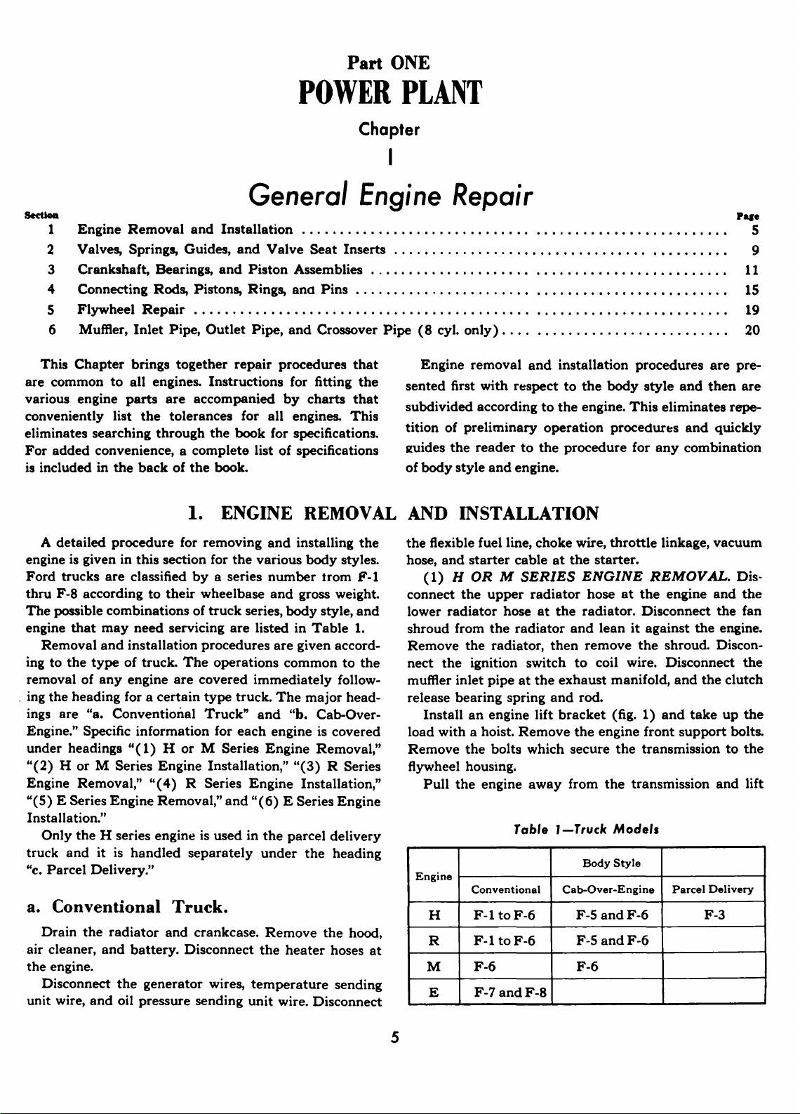
(1)
H
OR M SERIES
connect
lower
shroud
Remove
nect
muffler
release
load
Remove
flywheel housing.
Engine
radiator
from
the
Install
with
Pull
H
R
M
E
the
upper
the
the
radiator,
ignition
inlet
pipe
bearing
an
engine
a hoist.
the
bolts
the
engine
Conventional
F-l
to
F-l
to
F-6
F-7
andF-8
cable
radiator
hose
radiator
switch
at
spring
Remove
which
away
Tabl.
F-6
F-6
the
lift
choke
wire,
at
the
ENGINE
hose
at
the
radiator.
and
then
remove
to
exhaust
and
rod.
bracket
the
secure
from
J-Truck
Body
Cab-Over-Engine
F-S
F-5
F-6
throttle
starter.
at
the
Disconnect
lean
it
against
the
coil wire.
manifold,
(fig.
1)
engine
and
and
front
the
transmission
the
transmission
Models
Style
F-6
F-6
linkage,
vacuum
REMOVAL.
engine
shroud. DisconDisconnect
and
the
and
the
take
support
Parcel
F-3
and
the
engine.
and
Delivery
Dis-
the
fan
the
clutch
up
the
bolts.
to
the
lift
5
6
the
engine
strike
(2) H OR M SERIES
To
install
ment
transmission into Bny gear. Start
shaft
not
mesh, turn
on
the
shaft slides into
Install
tighten
engine
the engine.
Connect
pipe, and ignition switch
over
Fasten
radiator hoses.
To
starter cable,
temperature and pressure
wires,
and hood.
ing to
(3) R SERIES
upper radiator hoses.
the generator
radiator
Disconnect
pipe,
the
Place
it from dropping
Inst
take
engine front support bolts.
flywheel housing bolts.
transmission
Do
(4)
install
and
mission into
from
the
chassis.
the
grille.
the
engine, lower it into
and
align
it
with
into
the
clutch
the
crankshaft
crankshaft
the
them
front
the
the
engine
the
complete
Bnd
heater hoses.
Fill
the
prevailing temperature.
damper
the
clutch
transmission
to
40-50
support
clutch
and install
fan shroud to
the
vacuum
the
cooling
ENGINE
belt
and generator. Disco
ho
ses
at
the
the
ignition switch
and
the
clutch
road
draft
tube.
a support under
out
all
the
engine
up
the
slack
in
and
lift it from
not
allow
the
engine
R
SERIES
the
engine,
align it
with
any
gear. Start
lower
the
Do
ENGINE
the
flywheel
disc spline.
slowly
retaining
disc spline.
to
flywheel
foot-pounds
bolts.
Remove
spring
engine
hose, throttle linkage,
to
coil wire.
the
sending
Install
system
and
the
installation,
REMOVAL.
Remove
radiator
pedal
retracting spring.
the
of line
the
lift
cables
Pull
to strike
when
hook
Remove
the
ENGINE
it into
flywheel' housing.
the
not
Chapter
allow
the
I-General
engine
INSTALLATION
the
engine
compart-
housing. Shift
the
transmission
If
the
spline
with
a box wrench
bolt
until
housing
torque.
the
lift
bracket
rod,
the
muffler inlet
Lean
the fan shroud
radiator.
radiator.
unit wires, generator
the
battery, air cleaner,
and
Connect
connect
crankcase accord-
grooves
the
bolts
Install
choke
main
main
from
wire,
Remove
the
fan
belt
and
fan,
nnect
the
lower
and
remove
to
coil wire, muffler
transmission
the
assembly
with
a hoist.
the
engine
the
engine
the
INSTALLATION
the
engine
transmission main shaft
the
radiator .
Remove
to
engine
is removed.
(fig.
Remove
transmission to
away
from
compartment.
grille.
compartment
Shift
the
prevent
2)
.
trans-
to
the
do
and
the
the
the
the
and
inlet
and
the
the
To
Engine Repair
into
the
clutch
mesh, turn
slides into
.
Install
tighten
front
assembly.
inlet
Install
Install
fan belt.
starter cable,
temperature
heater
battery, air cleaner,
and crankcase
uI--per
the
radiator
Disconnect
to
linkage. Loosen
and
inlet cross
exhaust
up
engine
prevent
is
housing
forward
the
stall
and
O
to
support
Connect
pipe, ground strap,
the
the
To
complete
hoses.
(5)
E'
radiator hoses.
generator
hoses
distributor high
remove
manifolds.
Install
the
slack
front support
removed.
to
engine
(6)
E
the
align
INSTAll HOOK
PPOSITE
disc spline.
the
crankshaft
the
clutch
the
transmission
40-50
the
radiator
generator
Adjust
vacuum
and
Install
according
SERIES
belt
the
the
over
the
engine
in
it from dropping
Remove
the engine
to
clear
from
SERIES
engine, lower it
it
with
disc
foot-pounds
bolts.
clutch
and
belt
the
oil
Remove
pedal
and
connect
and
tension.
engine
hose,
pressure
the
and
ENGINE
Remove
and
generator.
at
the
radiator
distributor primary wire
tension
the
road
road draft tube.
pipe
and
lift
hook
the
cables
bolts
the
block.
the
transmission
the
chassis.
ENGINE
the
flywheel housing.
PLATES
ON
OF
ENGINE
If
the
spline
slowly
spline
.
to
flywheel housing
until
grooves do
the
torque. Install
the
engine lift hook
retracting spring, muffler
ignition
generator
Install
installation,
throttle
road
hood..
to
the
REMOVAL.
wire.
draft
muffler
assembly
with
. Support
out
bolts
Move
switch
the
lower radiator hoses.
belt
the
linkage,
sending
draft
Fill
the
prevailing temperatures.
to
and
the
radiator
connect
unit wires, and
tube. Install
cooling
Re
the
fan
belt
and
Disconnect
and
remove
Disconnect
tube
clamp
Disconnect
inlet
the
and
at
pipe
(fig.
a hoist.
the
of line
that
secure
the
main
Remove
transmission to
when
the
engine
shaft, then lift
INSTALLATION.
into
the
engine
compartment
Shift
~
~--To
not
main
shaft
bolts
and
the
engine
coil wire.
fan and
hoses.
the
choke
wire,
the
system
move
the
fan and
the
lower
radiator.
the
coil
the
throttle
the
elbow
the
muffler
from the
2)
and
take
the
the
engine
flywheel
far enough
To
in-
the
trans-
o/_6000·N
fig
E
ngi
ne liffi
Too/_6000
:
'-Engine
ng
Eye
·P
Lift Bracket for H
or
M Series Engines
1216
Fig.
2-fngine
Liff
Hook
Assembly
for
8-Cylinder
1185
fngines
Section
l-Engine
Removal
and
Installation
7
mission
from
until
spline
until
torque
front
turning.
the
gooves
the
Install
support
into
main
main
the
them
any
gear.
Move
shaft
do
not
shaft
flywheel
to
40-50
bolts.
This
the
engine
enters
mesh,
slides
housing
foot-pounds.
Remove
assembly.
Connect
cross
road
and
the
the
rad
sta
ll
the
fan belt.
radiator
To
starter
wire,
heater
Fill
the
prevailing
the
over
pipe
draft
tube. Connect
coil
to
iator
and
generator
Adjust
hoses.
complete
cable,
temperature
hoses.
Install
cooling
temperatures.
muffler
to
the
distributor
connect
and
the
the
vacuum
and
the
system
inlet
exhaust
generator
belt
engine
hose,
pressure
battery,
and crankcase
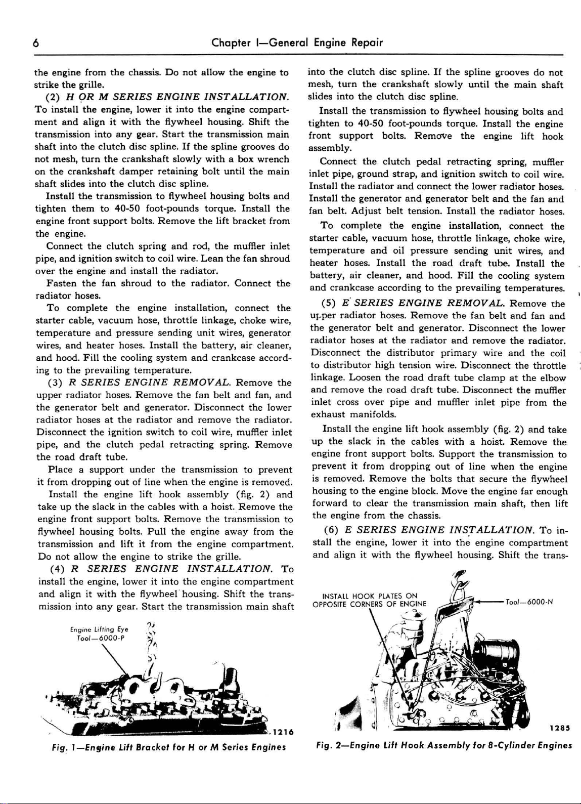
b. Cab.Over.Engine.
Begin
crankcase
,.Ieaner
dash
front
co
nnect
support
coil
sendi
starter
wire,
muffler
Remove
the
engine
and
and
flexible
panel.
Disconnect
wire, temperature
ng
and
wheel.
the
assemb
unit
motor
heater
in
let
the
Remove
Remove
radiator
the
wire,
cable
pipe, and
engine
removal
cooling
tube,
the
ly
with
generator
vacuum
at
hoses. D
front
system.
oi l filter lines.
the
hos
the
sending
the
isconnect
clutch
will
keep
toward
the
clutch
turn
the
into
the
to
the
pipe
manifolds.
the
distributor
high
tension
the
low
er
belt
tension. Install
installation,
throttle
sending
air
operation
Remove
floor
pan
over
grille
assembly
es
and
remove
radiator
wires,
unit
hose
at
the
starter,
support
throttle
the
release
bolts.
the
main
the
transmission
disc
spline.
crankshaft
clutch
engine
Install
engine
and
muffler
primary
wire.
radiator
and
connect
linkag
unit
cleaner,
according
by
draining the
the
the
Remove
(fig.
the
(fig. 4).
ignition
wire
, oil
intake manifold,
link
flexible fuel line,
bea
If
slowly
disc
spline.
bolts
the
engine
lift
Install
Install
hoses.
the
fan
the
upper
e,
choke
wires,
and
hood.
to
hood, a
engine,
either
3). Disradiator
switch
pressure
age,
choke
ring sprin
shaft
the
and
hook
inlet
the
wire
In-
and
the
and
the
ir
and
to
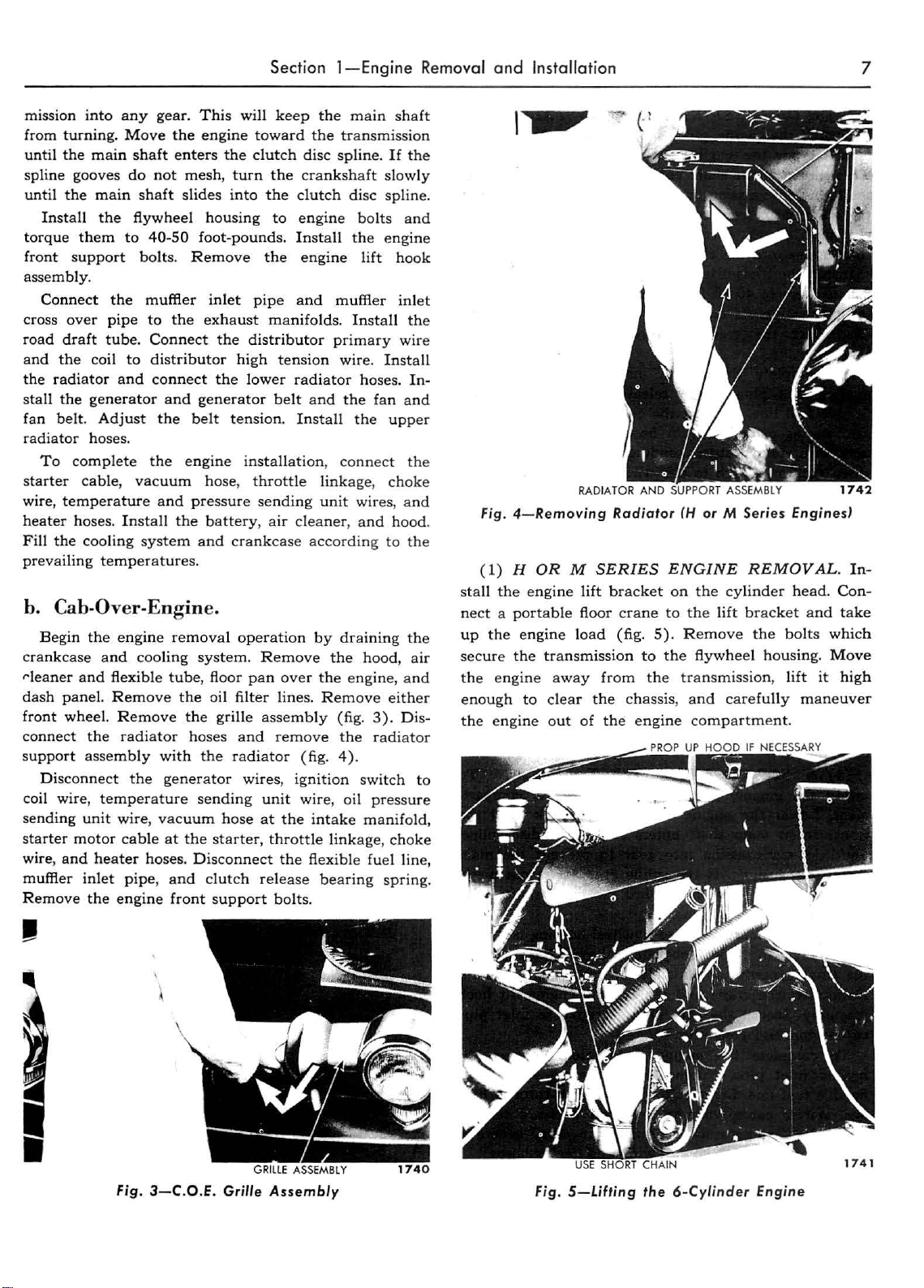
(1) H OR M SERIES
stall
nect a portable
up
secure
the
enough
the engine
g.
\,.,
Fig.
4-Removing
the
the
engine
the
eng
ine
engine
load
transmission
away
to
clear
out
Radiator
lift
bracket
floor c
rane
(fig. 5). Remove
to
from
the
the
chassis,
of
the
engine
(H
or
M
ENGINE
on
the
cylinder
to
the
lift
the
flywhe
transmission,
and
carefully
com
partment.
Series
Engines]
REMOVAL.
head.
bracket
the
el
and
bolts which
housing.
lift
maneuver
Move
it
In-
Con-
take
high
Fig.
\
3-C.O.E
. Grille
Assembly
Fig.
5-Lifting
the
6-Cylinder
Engine
 Loading...