

Page 1

48-Port Gigabit Ethernet Line Card with SFP Optics
FN00048A
Catalog Number: LC-EG-1GE-48P
Card Highlights
• Uses approved 1G Small-form Factor Pluggable (SFP) laser modules. Laser modules must comply with 21
CFR 1040 Class 1 requirements.
• Pluggable SFP optics providing support for SR, LR, ER, and ZR optical interfaces
• The EG series line cards support two 18Mb user configurable Content Addressable Memory (CAM)
modules with flexible partition assignments. The CAM forwarding table has the following maximum
entries:
• 32K Layer 2 Forward Information Base (FIB)
• 1K Ingress and Egress Layer 2 Access Control List (ACL)
• 512K IPv4 FIB
• 24K IPv4 Flow
• 12K Ingress IPv4 ACL
• 1K Egress IPv4 ACL
• 32K IPv6 FIB
• 4K IPv6 Flow (at 576 Bits)
• 3K Ingress IPv6 ACL (at 576 Bits)
• 1K Egress IPv6 ACL (at 576 Bits)
• Supports online insertion and removal (OIR) of line card
• Supports ingress and egress Layer 2 and Layer 3 ACL processing across all ports.
• Supports full duplex only
• Requires FTOS 7.5.1.0 or higher
Label Description
Port 48 1G Small-form Factor Pluggable (SFP) Ports
Port LEDs
Green = link up
Unlit = port is down
Flashing Green = activity
Laser Warning This is a Class 1 laser product which emits invisible laser radiation. This product
complies with CDRH 21 CFR 1040
Status LED Flashing Green = Initializing
Green = Line card online
Amber = Failed power-on self test or fault detected
Unlit = No power to the line card or the line card is administratively shut down
101-00198-02
Page 2

Warning: Electrostatic discharge (ESD) damage can occur if components are mishandled. Always wear
an ESD-preventive wrist or ankle strap when handling line cards. Connect the ESD strap to the
grounding plug. Place line cards on an antistatic surface and store in anti-static bags when they are not
installed.
Installation Instructions
The E-Series system line cards are hot-swappable. You can add, replace, or remove a card without interrupting the
system power or system operations. If you insert a new line card into a slot occupied by a blank panel or if you
hot-swap identical card types, no additional configuration is necessary.
Installation Notes:
• Do not remove a blank panel from the chassis until you are ready to install a line card into that slot. If
you remove a card, immediately fill the empty slot with a blank. Blanks are required to control airflow
and electromagnetic interference.
• Line cards fit only in chassis slots 0 through 13 in an E1200/E1200i chassis and slots 0 through 6 in the
E600/E600i chassis. Chassis slots R0 and R1 are designed for the route processor modules (RPMs).
• If you replace an existing line card with a different series line card, you must configure the system with
the updated line-card information.
Install a line card
Step Task
1 Hold the line card by the edges. Avoid touching the printed circuit board and connector pins. Extend the
top and bottom line-card levers before you insert the line card into the slot.
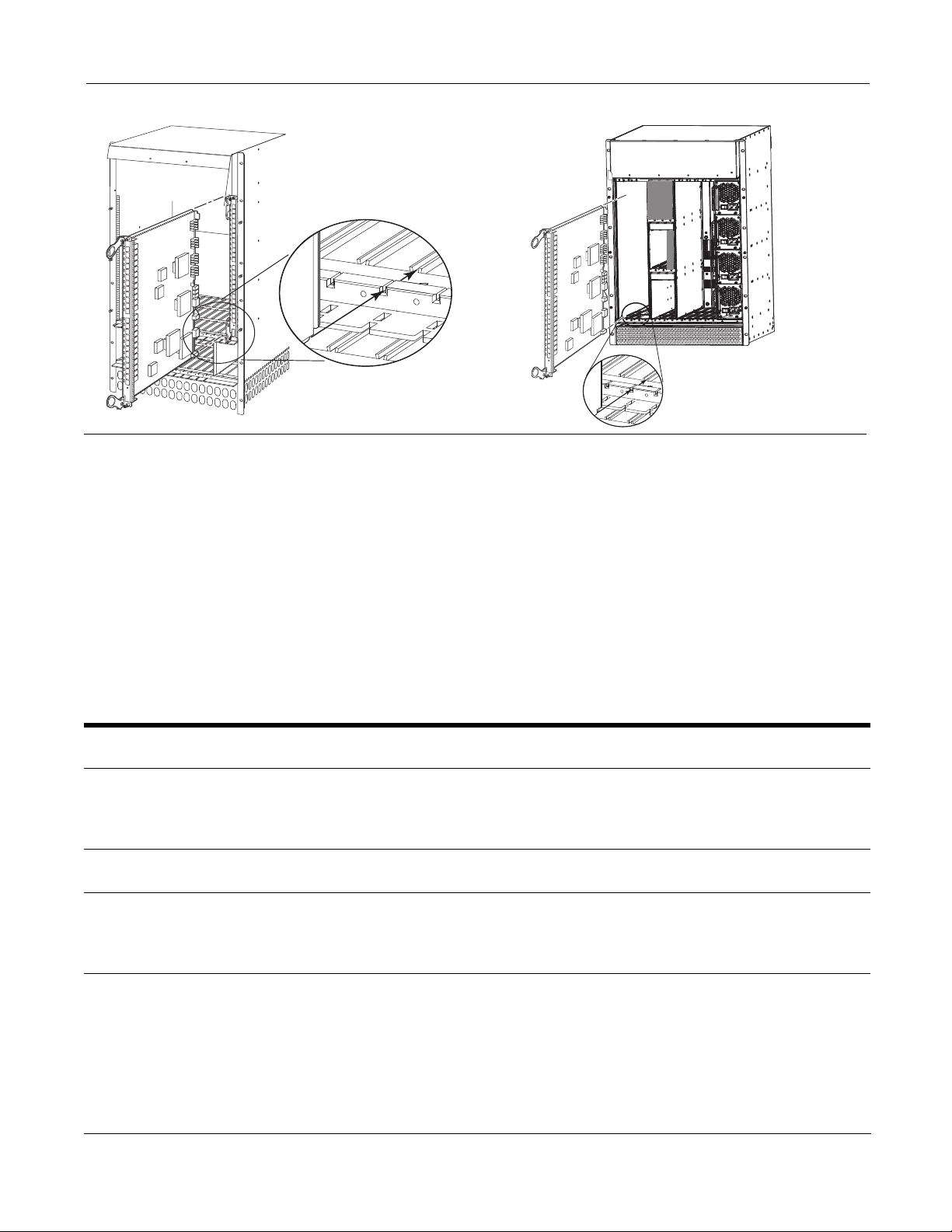
Align the card with the upper and lower card guides and gently slide the card into the slot until you feel
the connectors engage with the chassis backplane.
2
Rotate the levers to seat the backplane connectors and lock the line card in place.
3
Secure the line card in place by tightening the top and bottom screws on each line card, using a #2
Phillips screwdriver.
2 101-00198-02
Page 3
FN00079d
FN00036B
Figure 1 Inserting a line card into an E1200/E1200i (left) and an E600/E600i (right)
CLI Commands
It is not necessary to configure a slot when you install a new line card into a slot currently occupied by a blank or if
you replace (hot-swap) identical card types. You can also pre-configure an empty line card slot (virtual line card) if
you know which card you will be inserting into the empty slot. For more information on configuring a slot for a
new line card, refer to the FTOS Command Line Interface Reference.
To replace the current card with a different line-card type
Step Task
1 Remove the existing card from the chassis slot.
2
In the CONFIGURATION mode, execute the no linecard number command to remove the old line card
type configuration. Where number is the chassis slot number (range: 0 to 13 for the E1200/E1200i and
0 to 6 for the E600/E600i).
3
Insert the new card. FTOS will detect the new line card and enter it in the running configuration.
4
In the EXEC privilege mode, enter the copy running-config file-url command to save the
configuration. Where file-url is the location to save the file. To view a list of possible file locations, enter
copy running-config ?
101-00198-02 3
Page 4

Pre-configure a line card slot
Step Task
1 In the CONFIGURATION mode, enter the linecard number card-type command with the card
information. Where number is the chassis slot number (range: 0 to 13 for the E1200/E1200i and 0 to 6
for the E600/E600i) and card-type is the line card indicator.
2
In the EXEC privilege mode, enter the copy running-config file-url command to save the
configuration. Where file-url is the location to save the file. To view a list of possible file locations, enter
the copy running-config ? command.
3
The slot is now configured for your virtual line card. Ensure that you insert only the line card type that
you named in step 1.
To view line-card and chassis configurations, use the following commands:
show linecard [number] [brief]
show chassis [brief]
4 101-00198-02
 Loading...