

Page 1

PENT/CPCI-735R2/736R2 Family
Reference Guide
P/N 221843 Revision AC
January 2004
Page 2

Copyright
The information in this publication is subject to change without notice. Force Computers, GmbH reserves the right to make
changes without notice to this, or any of its products, to improve reliability, performance, or design.
Force Computers , GmbH shall n ot be liable f or technic al or editor ial error s or omissio ns contained he rein, nor for indirect, special,
incidental, or consequential damages resulting from the furnishing, performance, or use of this material. This information is provided “as is” and Force Computers, GmbH expressly disclaims any and all warranties, express, implied, statutory, or otherwise,
including without limitation, any express, statutory, or implied warranty of merchantability, fitness for a particular purpose, or
non-infringement.
This publication contai ns informat ion protected by copyright. T his public ation shall not be reproduced , transmit ted, or stored in
a retrieval system, nor its contents used for any purpose, without the prior written consent of Force Computers, GmbH.
Force Computers, GmbH assumes no responsibility for the use of any circuitry other than circuitry that is part of a product of
Force Computers, GmbH. Force Computers, GmbH does not convey to the purchaser of the product descri bed herein any license
under the patent rights of Force Computers, GmbH nor the rights of others.
Copyright
The Force logo is a trademark of Force Computers, GmbH. SENTINEL is a registered trademark of Force Computers, GmbH
IEEE is a registered trademark of the Institute for Electrical and Electronics Engineers, Inc.
PICMG, CompactPCI, and the CompactPCI logo are registered trademarks and the PICMG logo is a t rademark of the PCI Industrial Computer Manufact u r e r’s Group.
MS-DOS, Windows95, Windows98, Windows2000 and Windows NT are registered trademarks and the logos are a trademark of
the Microsoft Corporation .
Intel and Pentium are registered trademarks and the Intel logo is a trademark of the Intel Corporation.
SPARC is a registered trademark, the SPARC logo is a trademark and UltraSPARC is a registered trademark of SPARC International, I nc.
PowerPC is a registered trad e m ark and the PowerPC logo is a trademark of Internationa l Business Machines Corp oration.
AltiVec is a registered trademark and the AltiVec logo is a trademark of Motorola, Inc.
Sun, Sun Microsystems, the Sun logo, SPARCengine Ult ra, Solari s, Open Bo ot, SunVTS are trademarks or regis tered t rademarks
of SUN Microsystems, Inc.
The Linux Kernel is Copyright
GoAhead ia a registered trademark of GoAhead Software, Inc. and SelfReliant and Self Availability are trademarks of GoAhead
Software, Inc
LynxOS and BlueCat are registered trademarks of LynuxWorks, Inc.
Tornado, VxWorks, Wind, W in d Nav igator, Wind River Systems, Win d Riv e r Syst e m s an d d esign , WindView, WinRouter and
Xmath are registered trademarks or service marks of Wind River Systems, Inc.
Envoy, the Tornado logo, Wind River, and Zinc are trademarks or service marks of Wind River Systems, Inc.
Sony is a registered trademark of Sony Corporation, Japa n
Ethernet is a trademark an d Xe rox is a registered trademark of Xerox Corporation
2004 by Force Computers, GmbH. All rights reserved.
Linus B. Torvalds under the terms of the General Public License (GPL).
.
Other product names mentioned herein may be trademarks and/or registered trademarks of their respective companies.
Page 3

World Wide Web: www.fci.com
24-hour access to on-line manuals, driver updates, and application
notes is provided via SMART, our SolutionsPLUS customer support
program that provides current technical and services information.
Headquarters
The Americas Europe Asia
Force Computers Inc.
4211 Starboard Drive
Fremont CA 94538
Tel.: +1 (510) 624-5300
Fax: +1 (510) 624-5301
Email: [email protected]
Force Computers GmbH
Lilienthalstr. 15
D-85579 Neubiberg/München
Tel.: +49 (89) 608 14-0
Fax: +49 (89) 609 77 93
Email: [email protected]
Force Computers Japan K.K.
Shibadaimon MF Bldg. 4F
Shiba Daimon 2-1-16
Minato-ku, Tokyo 105-0012
Tel.: +81 (03) 3437-3948
Fax: +81 (03) 3437-3968
Email: [email protected]
221843 420 000 AC
Page 4

Page 5

Using This Guide
Other Sources of Information
Contents
Safety Notes
Sicherheitshinweise
1 Introduction
Features . . . . . . . . . . . . . . . . . . . . . . . . . . . . . . . . . . . . . . . . . . . . . . . . . . . . . . . . . 1-3
Variants . . . . . . . . . . . . . . . . . . . . . . . . . . . . . . . . . . . . . . . . . . . . . . . . . . . . . . . . . 1-4
Standard Compliances . . . . . . . . . . . . . . . . . . . . . . . . . . . . . . . . . . . . . . . . . . . . . 1-5
Ordering Information . . . . . . . . . . . . . . . . . . . . . . . . . . . . . . . . . . . . . . . . . . . . . . 1-6
Product Nomenclature . . . . . . . . . . . . . . . . . . . . . . . . . . . . . . . . . . . . . . . . . . . . . . . . . . . . . . . . . . . .1-6
Order Numbers . . . . . . . . . . . . . . . . . . . . . . . . . . . . . . . . . . . . . . . . . . . . . . . . . . . . . . . . . . . . . . . . . . 1-6
PENT/CPCI-735R2/736R2 Family v
Page 6

2Installation
Action Plan . . . . . . . . . . . . . . . . . . . . . . . . . . . . . . . . . . . . . . . . . . . . . . . . . . . . . . 2-3
Requirements . . . . . . . . . . . . . . . . . . . . . . . . . . . . . . . . . . . . . . . . . . . . . . . . . . . . 2-5
Environmental Requirements . . . . . . . . . . . . . . . . . . . . . . . . . . . . . . . . . . . . . . . . . . . . . . . . . . . . . . . 2-5
Power Requirements . . . . . . . . . . . . . . . . . . . . . . . . . . . . . . . . . . . . . . . . . . . . . . . . . . . . . . . . . . . . . 2-7
Hardware Upgrades and Accessories . . . . . . . . . . . . . . . . . . . . . . . . . . . . . . . . 2-8
Memory Module . . . . . . . . . . . . . . . . . . . . . . . . . . . . . . . . . . . . . . . . . . . . . . . . . . . . . . . . . . . . . . . . . 2-8
PMC Module . . . . . . . . . . . . . . . . . . . . . . . . . . . . . . . . . . . . . . . . . . . . . . . . . . . . . . . . . . . . . . . . . . . 2-9
Voltage Key . . . . . . . . . . . . . . . . . . . . . . . . . . . . . . . . . . . . . . . . . . . . . . . . . . . . . . . . . . . . . . . . . 2-9
Installation Procedure . . . . . . . . . . . . . . . . . . . . . . . . . . . . . . . . . . . . . . . . . . . . . . . . . . . . . . . . . 2-10
Removal Procedure . . . . . . . . . . . . . . . . . . . . . . . . . . . . . . . . . . . . . . . . . . . . . . . . . . . . . . . . . . 2-11
IDE Devices . . . . . . . . . . . . . . . . . . . . . . . . . . . . . . . . . . . . . . . . . . . . . . . . . . . . . . . . . . . . . . . . . . . 2-12
Hard-Disk Drive Accessory Kit . . . . . . . . . . . . . . . . . . . . . . . . . . . . . . . . . . . . . . . . . . . . . . . . . . 2-13
Rear Transition Board . . . . . . . . . . . . . . . . . . . . . . . . . . . . . . . . . . . . . . . . . . . . . . . . . . . . . . . . . . . 2-14
Switch Settings . . . . . . . . . . . . . . . . . . . . . . . . . . . . . . . . . . . . . . . . . . . . . . . . . . 2-15
Board Installation . . . . . . . . . . . . . . . . . . . . . . . . . . . . . . . . . . . . . . . . . . . . . . . . 2-18
Installation in a Nonpowered System . . . . . . . . . . . . . . . . . . . . . . . . . . . . . . . . . . . . . . . . . . . . . . . . 2-18
Installation Procedure . . . . . . . . . . . . . . . . . . . . . . . . . . . . . . . . . . . . . . . . . . . . . . . . . . . . . . . . . 2-18
Removal Procedure . . . . . . . . . . . . . . . . . . . . . . . . . . . . . . . . . . . . . . . . . . . . . . . . . . . . . . . . . . 2-19
Installation in a Powered System . . . . . . . . . . . . . . . . . . . . . . . . . . . . . . . . . . . . . . . . . . . . . . . . . . . 2-19
Signals . . . . . . . . . . . . . . . . . . . . . . . . . . . . . . . . . . . . . . . . . . . . . . . . . . . . . . . . . . . . . . . . . . . . 2-20
Control Elements . . . . . . . . . . . . . . . . . . . . . . . . . . . . . . . . . . . . . . . . . . . . . . . . . . . . . . . . . . . . 2-20
Removal Procedure . . . . . . . . . . . . . . . . . . . . . . . . . . . . . . . . . . . . . . . . . . . . . . . . . . . . . . . . . . 2-20
Installation Procedure . . . . . . . . . . . . . . . . . . . . . . . . . . . . . . . . . . . . . . . . . . . . . . . . . . . . . . . . . 2-21
Software Upgrades and Accessories . . . . . . . . . . . . . . . . . . . . . . . . . . . . . . . . 2-23
BIOS Upgrade . . . . . . . . . . . . . . . . . . . . . . . . . . . . . . . . . . . . . . . . . . . . . . . . . . . . . . . . . . . . . . . . . 2-23
NT-Support-Package . . . . . . . . . . . . . . . . . . . . . . . . . . . . . . . . . . . . . . . . . . . . . . . . . . . . . . . . . . . . 2-23
3 Controls, Indicators, and Connectors
Front Panel . . . . . . . . . . . . . . . . . . . . . . . . . . . . . . . . . . . . . . . . . . . . . . . . . . . . . . 3-3
PMC Cutouts . . . . . . . . . . . . . . . . . . . . . . . . . . . . . . . . . . . . . . . . . . . . . . . . . . . . . . . . . . . . . . . . . . . 3-4
LEDs . . . . . . . . . . . . . . . . . . . . . . . . . . . . . . . . . . . . . . . . . . . . . . . . . . . . . . . . . . . . . . . . . . . . . . . . . 3-5
Keys . . . . . . . . . . . . . . . . . . . . . . . . . . . . . . . . . . . . . . . . . . . . . . . . . . . . . . . . . . . . . . . . . . . . . . . . . . 3-6
Connectors . . . . . . . . . . . . . . . . . . . . . . . . . . . . . . . . . . . . . . . . . . . . . . . . . . . . . . . . . . . . . . . . . . . . . 3-7
vi PENT/CPCI-735R2/736R2 Family
Page 7

On-Board Connectors . . . . . . . . . . . . . . . . . . . . . . . . . . . . . . . . . . . . . . . . . . . . . 3-9
CompactPCI Connectors . . . . . . . . . . . . . . . . . . . . . . . . . . . . . . . . . . . . . . . . . . . . . . . . . . . . . . . . . . 3-9
J1 and J2 . . . . . . . . . . . . . . . . . . . . . . . . . . . . . . . . . . . . . . . . . . . . . . . . . . . . . . . . . . . . . . . . . . . .3-9
J3 . . . . . . . . . . . . . . . . . . . . . . . . . . . . . . . . . . . . . . . . . . . . . . . . . . . . . . . . . . . . . . . . . . . . . . . . .3-10
J4 . . . . . . . . . . . . . . . . . . . . . . . . . . . . . . . . . . . . . . . . . . . . . . . . . . . . . . . . . . . . . . . . . . . . . . . . .3-11
J5 . . . . . . . . . . . . . . . . . . . . . . . . . . . . . . . . . . . . . . . . . . . . . . . . . . . . . . . . . . . . . . . . . . . . . . . . .3-12
IDE Connector . . . . . . . . . . . . . . . . . . . . . . . . . . . . . . . . . . . . . . . . . . . . . . . . . . . . . . . . . . . . . . . . .3-13
PMC Connectors . . . . . . . . . . . . . . . . . . . . . . . . . . . . . . . . . . . . . . . . . . . . . . . . . . . . . . . . . . . . . . .3-14
4BIOS
Introduction . . . . . . . . . . . . . . . . . . . . . . . . . . . . . . . . . . . . . . . . . . . . . . . . . . . . . . 4-3
Changing Configuration Settings . . . . . . . . . . . . . . . . . . . . . . . . . . . . . . . . . . . . 4-4
Selecting The Boot Device . . . . . . . . . . . . . . . . . . . . . . . . . . . . . . . . . . . . . . . . . . 4-5
Via Setup . . . . . . . . . . . . . . . . . . . . . . . . . . . . . . . . . . . . . . . . . . . . . . . . . . . . . . . . . . . . . . . . . . . . . .4-5
Via Boot Selection Menu . . . . . . . . . . . . . . . . . . . . . . . . . . . . . . . . . . . . . . . . . . . . . . . . . . . . . . . . . .4-6
Booting the Board via Network . . . . . . . . . . . . . . . . . . . . . . . . . . . . . . . . . . . . . . 4-7
Serial Console Redirection . . . . . . . . . . . . . . . . . . . . . . . . . . . . . . . . . . . . . . . . . 4-8
Requirements . . . . . . . . . . . . . . . . . . . . . . . . . . . . . . . . . . . . . . . . . . . . . . . . . . . . . . . . . . . . . . . . . . .4-8
Remote Configuration . . . . . . . . . . . . . . . . . . . . . . . . . . . . . . . . . . . . . . . . . . . . . . . . . . . . . . . . . . . . .4-9
Remote Configuration Set . . . . . . . . . . . . . . . . . . . . . . . . . . . . . . . . . . . . . . . . . . . . . . . . . . . . . . .4-9
Remote Configuration Not Set . . . . . . . . . . . . . . . . . . . . . . . . . . . . . . . . . . . . . . . . . . . . . . . . . . . . 4-9
Updating BIOS . . . . . . . . . . . . . . . . . . . . . . . . . . . . . . . . . . . . . . . . . . . . . . . . . . 4-11
Downloading Software from S.M.A.R.T. . . . . . . . . . . . . . . . . . . . . . . . . . . . . . . . . . . . . . . . . . . . . . .4-11
Update Procedure . . . . . . . . . . . . . . . . . . . . . . . . . . . . . . . . . . . . . . . . . . . . . . . . . . . . . . . . . . . . . . .4-11
BIOS Messages . . . . . . . . . . . . . . . . . . . . . . . . . . . . . . . . . . . . . . . . . . . . . . . . . . 4-12
PENT/CPCI-735R2/736R2 Family vii
Page 8

5 Buses
Block Diagram . . . . . . . . . . . . . . . . . . . . . . . . . . . . . . . . . . . . . . . . . . . . . . . . . . . . 5-3
PCI Local Bus 0 . . . . . . . . . . . . . . . . . . . . . . . . . . . . . . . . . . . . . . . . . . . . . . . . . . . 5-4
Ethernet . . . . . . . . . . . . . . . . . . . . . . . . . . . . . . . . . . . . . . . . . . . . . . . . . . . . . . . . . . . . . . . . . . . . . . . 5-4
PMC2 . . . . . . . . . . . . . . . . . . . . . . . . . . . . . . . . . . . . . . . . . . . . . . . . . . . . . . . . . . . . . . . . . . . . . . . . . 5-5
SENTINEL . . . . . . . . . . . . . . . . . . . . . . . . . . . . . . . . . . . . . . . . . . . . . . . . . . . . . . . . . . . . . . . . . . . . . 5-5
ISA Bridge . . . . . . . . . . . . . . . . . . . . . . . . . . . . . . . . . . . . . . . . . . . . . . . . . . . . . . . . . . . . . . . . . . . . . 5-8
IDE Interfaces . . . . . . . . . . . . . . . . . . . . . . . . . . . . . . . . . . . . . . . . . . . . . . . . . . . . . . . . . . . . . . . . 5-8
USB . . . . . . . . . . . . . . . . . . . . . . . . . . . . . . . . . . . . . . . . . . . . . . . . . . . . . . . . . . . . . . . . . . . . . . . 5-9
SMB Interface . . . . . . . . . . . . . . . . . . . . . . . . . . . . . . . . . . . . . . . . . . . . . . . . . . . . . . . . . . . . . . . . 5-9
PCI Local Bus 1 . . . . . . . . . . . . . . . . . . . . . . . . . . . . . . . . . . . . . . . . . . . . . . . . . . 5-10
PMC1 . . . . . . . . . . . . . . . . . . . . . . . . . . . . . . . . . . . . . . . . . . . . . . . . . . . . . . . . . . . . . . . . . . . . . . . . 5-10
M66EN . . . . . . . . . . . . . . . . . . . . . . . . . . . . . . . . . . . . . . . . . . . . . . . . . . . . . . . . . . . . . . . . . . . . 5-10
REQ64_N and ACK64_N . . . . . . . . . . . . . . . . . . . . . . . . . . . . . . . . . . . . . . . . . . . . . . . . . . . . . . 5-10
ISA Bus . . . . . . . . . . . . . . . . . . . . . . . . . . . . . . . . . . . . . . . . . . . . . . . . . . . . . . . . 5-11
Flash Memory . . . . . . . . . . . . . . . . . . . . . . . . . . . . . . . . . . . . . . . . . . . . . . . . . . . . . . . . . . . . . . . . . 5-11
SRAM . . . . . . . . . . . . . . . . . . . . . . . . . . . . . . . . . . . . . . . . . . . . . . . . . . . . . . . . . . . . . . . . . . . . . . . . 5-12
Serial Port COM3 . . . . . . . . . . . . . . . . . . . . . . . . . . . . . . . . . . . . . . . . . . . . . . . . . . . . . . . . . . . . . . . 5-12
Super I/O Controller . . . . . . . . . . . . . . . . . . . . . . . . . . . . . . . . . . . . . . . . . . . . . . . . . . . . . . . . . . . . . 5-13
Real Time Clock . . . . . . . . . . . . . . . . . . . . . . . . . . . . . . . . . . . . . . . . . . . . . . . . . . . . . . . . . . . . . 5-13
Serial Ports . . . . . . . . . . . . . . . . . . . . . . . . . . . . . . . . . . . . . . . . . . . . . . . . . . . . . . . . . . . . . . . . . 5-13
Floppy Disk Interface . . . . . . . . . . . . . . . . . . . . . . . . . . . . . . . . . . . . . . . . . . . . . . . . . . . . . . . . . 5-14
Keyboard and Mouse . . . . . . . . . . . . . . . . . . . . . . . . . . . . . . . . . . . . . . . . . . . . . . . . . . . . . . . . . 5-14
Parallel Port . . . . . . . . . . . . . . . . . . . . . . . . . . . . . . . . . . . . . . . . . . . . . . . . . . . . . . . . . . . . . . . . 5-14
Glue Logic FPGA . . . . . . . . . . . . . . . . . . . . . . . . . . . . . . . . . . . . . . . . . . . . . . . . . . . . . . . . . . . . . . . 5-14
IPMI Controller . . . . . . . . . . . . . . . . . . . . . . . . . . . . . . . . . . . . . . . . . . . . . . . . . . . . . . . . . . . . . . . . . 5-15
Temperature Sensor . . . . . . . . . . . . . . . . . . . . . . . . . . . . . . . . . . . . . . . . . . . . . . . . . . . . . . . . . . 5-16
Available IPMI Drivers . . . . . . . . . . . . . . . . . . . . . . . . . . . . . . . . . . . . . . . . . . . . . . . . . . . . . . . . 5-17
2
C Addresses . . . . . . . . . . . . . . . . . . . . . . . . . . . . . . . . . . . . . . . . . . . . . . . . . . . . . . . . . . . . . . . 5-18
I
I2C Bus . . . . . . . . . . . . . . . . . . . . . . . . . . . . . . . . . . . . . . . . . . . . . . . . . . . . . . . . . 5-19
6 Maps and Registers
Overview . . . . . . . . . . . . . . . . . . . . . . . . . . . . . . . . . . . . . . . . . . . . . . . . . . . . . . . . 6-3
I/O and Memory Maps . . . . . . . . . . . . . . . . . . . . . . . . . . . . . . . . . . . . . . . . . . . . . . 6-5
viii PENT/CPCI-735R2/736R2 Family
Page 9

FPGA 1 . . . . . . . . . . . . . . . . . . . . . . . . . . . . . . . . . . . . . . . . . . . . . . . . . . . . . . . . . . 6-8
SRAM Configuration Register . . . . . . . . . . . . . . . . . . . . . . . . . . . . . . . . . . . . . . . . . . . . . . . . . . . . . . .6-9
BIOS Support Register . . . . . . . . . . . . . . . . . . . . . . . . . . . . . . . . . . . . . . . . . . . . . . . . . . . . . . . . . . .6-10
LED Control Register . . . . . . . . . . . . . . . . . . . . . . . . . . . . . . . . . . . . . . . . . . . . . . . . . . . . . . . . . . . .6-11
Version Register . . . . . . . . . . . . . . . . . . . . . . . . . . . . . . . . . . . . . . . . . . . . . . . . . . . . . . . . . . . . . . . .6-12
Hardware Configuration Register . . . . . . . . . . . . . . . . . . . . . . . . . . . . . . . . . . . . . . . . . . . . . . . . . . .6-13
FPGA 2 . . . . . . . . . . . . . . . . . . . . . . . . . . . . . . . . . . . . . . . . . . . . . . . . . . . . . . . . . 6-14
Reset Control Register . . . . . . . . . . . . . . . . . . . . . . . . . . . . . . . . . . . . . . . . . . . . . . . . . . . . . . . . . . .6-15
Reset Status Register . . . . . . . . . . . . . . . . . . . . . . . . . . . . . . . . . . . . . . . . . . . . . . . . . . . . . . . . . . . .6-16
Software Reset Register . . . . . . . . . . . . . . . . . . . . . . . . . . . . . . . . . . . . . . . . . . . . . . . . . . . . . . . . . .6-17
Watchdog Retrigger Register . . . . . . . . . . . . . . . . . . . . . . . . . . . . . . . . . . . . . . . . . . . . . . . . . . . . . .6-17
Watchdog Control Register . . . . . . . . . . . . . . . . . . . . . . . . . . . . . . . . . . . . . . . . . . . . . . . . . . . . . . . .6-18
Flash Control Register . . . . . . . . . . . . . . . . . . . . . . . . . . . . . . . . . . . . . . . . . . . . . . . . . . . . . . . . . . . 6-20
Using 512 KByte BIOS Address Range . . . . . . . . . . . . . . . . . . . . . . . . . . . . . . . . . . . . . . . . . . . . 6-22
Using 1 MByte BIOS Address Range . . . . . . . . . . . . . . . . . . . . . . . . . . . . . . . . . . . . . . . . . . . . .6-22
Version Register . . . . . . . . . . . . . . . . . . . . . . . . . . . . . . . . . . . . . . . . . . . . . . . . . . . . . . . . . . . . . . . .6-23
IPMI IRQ Register . . . . . . . . . . . . . . . . . . . . . . . . . . . . . . . . . . . . . . . . . . . . . . . . . . . . . . . . . . . . . . .6-24
IPMI IRQ 0 . . . . . . . . . . . . . . . . . . . . . . . . . . . . . . . . . . . . . . . . . . . . . . . . . . . . . . . . . . . . . . . . . .6-24
IPMI IRQ 1 . . . . . . . . . . . . . . . . . . . . . . . . . . . . . . . . . . . . . . . . . . . . . . . . . . . . . . . . . . . . . . . . . .6-26
IPMI IRQ 2 . . . . . . . . . . . . . . . . . . . . . . . . . . . . . . . . . . . . . . . . . . . . . . . . . . . . . . . . . . . . . . . . . .6-27
L_ENUM IRQ Register . . . . . . . . . . . . . . . . . . . . . . . . . . . . . . . . . . . . . . . . . . . . . . . . . . . . . . . . . . .6-28
PMC 1 IRQ Register . . . . . . . . . . . . . . . . . . . . . . . . . . . . . . . . . . . . . . . . . . . . . . . . . . . . . . . . . . . . .6-29
COM 3 IRQ Register . . . . . . . . . . . . . . . . . . . . . . . . . . . . . . . . . . . . . . . . . . . . . . . . . . . . . . . . . . . . .6-30
Interrupt Status Register . . . . . . . . . . . . . . . . . . . . . . . . . . . . . . . . . . . . . . . . . . . . . . . . . . . . . . . . . .6-31
A Battery Exchange
B Troubleshooting
Index
Product Error Report
PENT/CPCI-735R2/736R2 Family ix
Page 10

x PENT/CPCI-735R2/736R2 Family
Page 11

Tables
Introduction
Table 1 Standard Compliance. . . . . . . . . . . . . . . . . . . . . . . . . . . . . . . . . . . . . . . . . . . . . . . . . 1-5
Table 2 Ordering Information Excerpt. . . . . . . . . . . . . . . . . . . . . . . . . . . . . . . . . . . . . . . . . . . 1-6
Installation
Table 3 Environmental Requirements. . . . . . . . . . . . . . . . . . . . . . . . . . . . . . . . . . . . . . . . . . . 2-5
Table 4 Power Requirements . . . . . . . . . . . . . . . . . . . . . . . . . . . . . . . . . . . . . . . . . . . . . . . . . 2-7
Table 5 Possible On-Board Upgrades and Accessories. . . . . . . . . . . . . . . . . . . . . . . . . . . . . 2-8
Table 6 Possible On-Board Upgrades and Accessories Combinations . . . . . . . . . . . . . . . . . 2-8
Table 7 Default Settings . . . . . . . . . . . . . . . . . . . . . . . . . . . . . . . . . . . . . . . . . . . . . . . . . . . . 2-16
Controls, Indicators, and Connectors
Table 8 Description of Front Panel LEDs . . . . . . . . . . . . . . . . . . . . . . . . . . . . . . . . . . . . . . . . 3-5
Table 9 U1 and IDE LEDs During Power Up . . . . . . . . . . . . . . . . . . . . . . . . . . . . . . . . . . . . .3-5
BIOS
Table 10 Default Settings for Remote Configuration. . . . . . . . . . . . . . . . . . . . . . . . . . . . . . . . . 4-9
Buses
Table 11 Devices on PCI Local Bus 0. . . . . . . . . . . . . . . . . . . . . . . . . . . . . . . . . . . . . . . . . . . . 5-4
Table 12 Ethernet Interface. . . . . . . . . . . . . . . . . . . . . . . . . . . . . . . . . . . . . . . . . . . . . . . . . . . .5-4
Table 13 SENTINEL SPROM Contents . . . . . . . . . . . . . . . . . . . . . . . . . . . . . . . . . . . . . . . . . .5-5
Table 14 System Management I
Table 15 Devices on PCI Local Bus 1. . . . . . . . . . . . . . . . . . . . . . . . . . . . . . . . . . . . . . . . . . . 5-10
Table 16 IPMI Driver Documentation . . . . . . . . . . . . . . . . . . . . . . . . . . . . . . . . . . . . . . . . . . . 5-17
Table 17 I2C Addresses of Devices Attached to IPMI Controller . . . . . . . . . . . . . . . . . . . . . . 5-18
Table 18 Devices on I
2
C Bus . . . . . . . . . . . . . . . . . . . . . . . . . . . . . . . . . . . . . . . . . . . . . . . . . 5-19
2
C Bus . . . . . . . . . . . . . . . . . . . . . . . . . . . . . . . . . . . . . . . . . . 5-9
PENT/CPCI-735R2/736R2 Family xi
Page 12

Maps and Registers
Table 19 Register Overview. . . . . . . . . . . . . . . . . . . . . . . . . . . . . . . . . . . . . . . . . . . . . . . . . . . 6-3
Table 20 Overview of IPMI Related Register Signals . . . . . . . . . . . . . . . . . . . . . . . . . . . . . . . 6-4
Table 21 I/O Address Ranges . . . . . . . . . . . . . . . . . . . . . . . . . . . . . . . . . . . . . . . . . . . . . . . . . 6-5
Table 22 Memory Address Map . . . . . . . . . . . . . . . . . . . . . . . . . . . . . . . . . . . . . . . . . . . . . . . . 6-6
Table 23 FPGA Address Map . . . . . . . . . . . . . . . . . . . . . . . . . . . . . . . . . . . . . . . . . . . . . . . . . 6-7
Table 24 Index Register FPGA 1 . . . . . . . . . . . . . . . . . . . . . . . . . . . . . . . . . . . . . . . . . . . . . . . 6-8
Table 25 SRAM Configuration Register . . . . . . . . . . . . . . . . . . . . . . . . . . . . . . . . . . . . . . . . . . 6-9
Table 26 BIOS Support Register . . . . . . . . . . . . . . . . . . . . . . . . . . . . . . . . . . . . . . . . . . . . . . 6-10
Table 27 LED Control Register . . . . . . . . . . . . . . . . . . . . . . . . . . . . . . . . . . . . . . . . . . . . . . . 6-11
Table 28 Version Register . . . . . . . . . . . . . . . . . . . . . . . . . . . . . . . . . . . . . . . . . . . . . . . . . . . 6-12
Table 29 Hardware Configuration Register . . . . . . . . . . . . . . . . . . . . . . . . . . . . . . . . . . . . . . 6-13
Table 30 Index Register FPGA 2 . . . . . . . . . . . . . . . . . . . . . . . . . . . . . . . . . . . . . . . . . . . . . . 6-14
Table 31 Reset Control Register 1. . . . . . . . . . . . . . . . . . . . . . . . . . . . . . . . . . . . . . . . . . . . . 6-15
Table 32 Reset Status Register . . . . . . . . . . . . . . . . . . . . . . . . . . . . . . . . . . . . . . . . . . . . . . . 6-16
Table 33 Software Reset Register . . . . . . . . . . . . . . . . . . . . . . . . . . . . . . . . . . . . . . . . . . . . . 6-17
Table 34 Watchdog Retrigger Register . . . . . . . . . . . . . . . . . . . . . . . . . . . . . . . . . . . . . . . . . 6-17
Table 35 Watchdog Control Register. . . . . . . . . . . . . . . . . . . . . . . . . . . . . . . . . . . . . . . . . . . 6-18
Table 36 Watchdog Timer . . . . . . . . . . . . . . . . . . . . . . . . . . . . . . . . . . . . . . . . . . . . . . . . . . . 6-19
Table 37 Flash Control Register. . . . . . . . . . . . . . . . . . . . . . . . . . . . . . . . . . . . . . . . . . . . . . . 6-20
Table 38 Flash Page Addressing. . . . . . . . . . . . . . . . . . . . . . . . . . . . . . . . . . . . . . . . . . . . . . 6-22
Table 39 Version Register . . . . . . . . . . . . . . . . . . . . . . . . . . . . . . . . . . . . . . . . . . . . . . . . . . . 6-23
Table 40 IPMI IRQ 0 Register . . . . . . . . . . . . . . . . . . . . . . . . . . . . . . . . . . . . . . . . . . . . . . . . 6-24
Table 41 IPMI IRQ 1 Register . . . . . . . . . . . . . . . . . . . . . . . . . . . . . . . . . . . . . . . . . . . . . . . . 6-26
Table 42 IPMI IRQ 2 Register . . . . . . . . . . . . . . . . . . . . . . . . . . . . . . . . . . . . . . . . . . . . . . . . 6-27
Table 43 L_ENUM Interrupt Register. . . . . . . . . . . . . . . . . . . . . . . . . . . . . . . . . . . . . . . . . . . 6-28
Table 44 PMC 1 IRQ Register . . . . . . . . . . . . . . . . . . . . . . . . . . . . . . . . . . . . . . . . . . . . . . . . 6-29
Table 45 COM 3 IRQ Register . . . . . . . . . . . . . . . . . . . . . . . . . . . . . . . . . . . . . . . . . . . . . . . . 6-30
Table 46 Interrupt Status Register . . . . . . . . . . . . . . . . . . . . . . . . . . . . . . . . . . . . . . . . . . . . . 6-31
xii PENT/CPCI-735R2/736R2 Family
Page 13

Figures
Introduction
Figure 1 Function Blocks . . . . . . . . . . . . . . . . . . . . . . . . . . . . . . . . . . . . . . . . . . . . . . . . . . . . .1-3
Installation
Figure 2 Voltage Key . . . . . . . . . . . . . . . . . . . . . . . . . . . . . . . . . . . . . . . . . . . . . . . . . . . . . . . . 2-9
Figure 3 PMC Connectors and Slots . . . . . . . . . . . . . . . . . . . . . . . . . . . . . . . . . . . . . . . . . . . 2-10
Figure 4 Position of Mounting Holes . . . . . . . . . . . . . . . . . . . . . . . . . . . . . . . . . . . . . . . . . . . 2-11
Figure 5 Flash Disk and IDE Connector . . . . . . . . . . . . . . . . . . . . . . . . . . . . . . . . . . . . . . . . 2-12
Figure 6 Location of Switches . . . . . . . . . . . . . . . . . . . . . . . . . . . . . . . . . . . . . . . . . . . . . . . .2-15
Figure 7 Button on Handle . . . . . . . . . . . . . . . . . . . . . . . . . . . . . . . . . . . . . . . . . . . . . . . . . . . 2-21
Controls, Indicators, and Connectors
Figure 8 Standard and Ethernet Front Panel . . . . . . . . . . . . . . . . . . . . . . . . . . . . . . . . . . . . . 3-3
Figure 9 Cutouts for PMC Modules on Standard and Ethernet Front Panel . . . . . . . . . . . . . . 3-4
Figure 10 Connectors of Standard and Ethernet Front Panel . . . . . . . . . . . . . . . . . . . . . . . . . .3-7
Figure 11 Additional Connectors of Ethernet Front Panel . . . . . . . . . . . . . . . . . . . . . . . . . . . . . 3-7
Figure 12 COM1 Connector Pinout . . . . . . . . . . . . . . . . . . . . . . . . . . . . . . . . . . . . . . . . . . . . . .3-8
Figure 13 KBD/MS - Keyboard and Mouse Connector Pinout . . . . . . . . . . . . . . . . . . . . . . . . .3-8
Figure 14 Ethernet 1 and 2 Connector Pinout . . . . . . . . . . . . . . . . . . . . . . . . . . . . . . . . . . . . . . 3-8
Figure 15 USB Connector Pinout . . . . . . . . . . . . . . . . . . . . . . . . . . . . . . . . . . . . . . . . . . . . . . .3-8
Figure 16 Location of CompactPCI Connectors (Top View) . . . . . . . . . . . . . . . . . . . . . . . . . . . 3-9
Figure 17 J3 Connector Pinout . . . . . . . . . . . . . . . . . . . . . . . . . . . . . . . . . . . . . . . . . . . . . . . .3-10
Figure 18 J4 Connector Pinout . . . . . . . . . . . . . . . . . . . . . . . . . . . . . . . . . . . . . . . . . . . . . . . .3-11
Figure 19 J5 Connector Pinout, Rows A-C . . . . . . . . . . . . . . . . . . . . . . . . . . . . . . . . . . . . . . . 3-12
Figure 20 J5 Connector Pinout, Rows D and E . . . . . . . . . . . . . . . . . . . . . . . . . . . . . . . . . . . .3-13
Figure 21 IDE Connector Pinout . . . . . . . . . . . . . . . . . . . . . . . . . . . . . . . . . . . . . . . . . . . . . . . 3-13
PENT/CPCI-735R2/736R2 Family xiii
Page 14

Figure 22 PMC Connectors and Slots . . . . . . . . . . . . . . . . . . . . . . . . . . . . . . . . . . . . . . . . . . 3-14
Figure 23 PN14 Connector Pinout . . . . . . . . . . . . . . . . . . . . . . . . . . . . . . . . . . . . . . . . . . . . . 3-15
Figure 24 PN24 Connector Pinout . . . . . . . . . . . . . . . . . . . . . . . . . . . . . . . . . . . . . . . . . . . . . 3-16
BIOS
Figure 25 Main Menu . . . . . . . . . . . . . . . . . . . . . . . . . . . . . . . . . . . . . . . . . . . . . . . . . . . . . . . . 4-4
Figure 26 Boot Device Order . . . . . . . . . . . . . . . . . . . . . . . . . . . . . . . . . . . . . . . . . . . . . . . . . . 4-5
Figure 27 Boot Menu . . . . . . . . . . . . . . . . . . . . . . . . . . . . . . . . . . . . . . . . . . . . . . . . . . . . . . . . 4-6
Buses
Figure 28 Location of Board Temperature Sensor . . . . . . . . . . . . . . . . . . . . . . . . . . . . . . . . . 5-16
Maps and Registers
Figure 29 Flash Device Page Map . . . . . . . . . . . . . . . . . . . . . . . . . . . . . . . . . . . . . . . . . . . . . 6-21
Battery Exchange
Figure 30 Battery Location . . . . . . . . . . . . . . . . . . . . . . . . . . . . . . . . . . . . . . . . . . . . . . . . . . . . A- 3
xiv PENT/CPCI-735R2/736R2 Family
Page 15

Using This Guide
This Reference Guide is intended for users quali fied in e lectronics or electrical engineering. Users must have a working understanding of Peripheral
Component Interconnect (PCI), Compact Peripheral Component Interconnect (CPCI), and telecommunications.
Style Conventions
Notation Description
1234 All numbers are decimal numbers except when used with the nota-
tions described below
00000000
0000
x Generic use of a letter
n Generic use of numbers
n.nn Decimal point indicator is signaled
Bold Character format used to emphasize a word
Courier Character format used for on-screen output
Courier+Bold Character format used to characterize user input
Italics Character format for references, table, and figure descriptions
<text> Typical notation used for variables and keys
[text] Typical notation for buttons
... Repeated item
.
.
.
.. Ranges
16
2
Typical notation for hexadecimal numbers (digits are 0 through F),
e.g. used for addresses and offsets
Same for binary numbers (digits are 0 and 1)
Omission of information from example/com ma nd that is not necessary at the time being
:Extents
| Logical OR
PENT/CPCI-735R2/736R2 Family xv
Page 16

Notation Description
Note:
Caution Possibly dangerous situation: slight injuries to people or damage to
Danger Dangerous situation: injuries to people or severe damage to objects
Product Naming Conventions
The following product names are used in this documentation:
Product Name Used Description
CPCI-735R2 PENT/CPCI-735R 2/736R2 Family and the standar d board vari-
CPCI-735AR2 Board variant wi th Ethernet via front panel
CPCI-736R2 PICMG 2.16 compliant variant with Ethernet via CPCI connec-
No danger encountered. Pay attention to important information
marked using this layout.
objects possible
possible
ant
tor
Abbreviations
BCD Binary-Coded Decimal
BIB Board Information Block
BIOS Basic Input Output System
BMC Base Board Management Controller
CMOS Complementary Metal Oxide Semiconductor
CPCI Compact Peripheral Component Interconnect
CPU Central Processing Unit
DHC Dual Host Controller
DRAM Dynamic Random Access Memory
ESD Electrostatic Discharge
xvi PENT/CPCI-735R2/736R2 Family
Page 17

FPGA Field-Programmable Gate Array
FRU Field Replaceable Unit
GND Ground
HSC Hot-Swap Controller
IDE Integrated Device Electronics
ICMB Intelligent Chassis Managem ent Bus
IPMB Intelligent Peripheral Management Bus
IPMI Intelligent Platform Management Interface
ITE Informationstechnische Einrichtung
KSC Keyboard Controller Style
LED Light Emitting Diode
LFM Linear Feet per Minute
NMI Nonmaskable Int err upt
PCI Peripheral Component Interconnect
PM Peripheral Management Controller
POST Power-On Self-Test
PSU Power Supply Unit
RAM Random Access Memory
ROM Read-On ly Memory
RTB Rear Tra ns ition Boar d
SBC Single-Board Computer
SDR Sensor Data Record
SDRAM Synchronous Dynamic Random Access Memory
SEL System Event Log
SMB Serial Management Bus
SPP Standard Parallel Port
SRAM Static RAM
TPE Twisted-Pair Ethernet
VGA Video Graphics Adapter
PENT/CPCI-735R2/736R2 Family xvii
Page 18

Revision History
Order No. Revision Date Description
215764 AA January 2002 Preliminary Installation Guide
215764 AB May 2002 Removed “Product Naming Conventions”
from Preface,
modified “EMC” page xxiii and “EMV”
page xxvii,
corrected safety note in “Installation in a
Powered System” page 2-20, “Hot Swap”
page xxv and page xxix,
replaces NVRAM by SRAM in Figure 1
“Function Blocks” page 1-3,
added information on IDE flash disk in
“Features” page 1-3,
corrected “Standard Compliances” page 15,
added note to “Standard Compliances”
page 1-5 and “Board Installation” page 2-19,
modified “Order Numbers” page 1-6,
added step to “Action Plan” page 2-3,
added safety note to “Environmental
Requirements” page 2-5,
modified Table 4 “Power Requirements”
page 2-7,
added information to “Rear Transition
Board” page 2-14,
modified note in “Connectors” page 3-7 and
“J5” page 3-12,
corrected list in “J3” page 3-10 and “J4”
page 3-11,
corrected Figure 21 “IDE Connector Pinout”
page3-13,
corrected pin 21 row B in Fig ure 19 “J5 Connector Pinout, Rows A-C” page3-12,
added README.1ST to list in “Update Procedure” page 4-11,
corrected information on I DE flash disk an d
CompactPCI bus in “Block Diagram”
page 5-3,
added information to “IPMI Controller”
page 5-15,
corrected CIB byte size in T able 18 “Devices
on I2C Bus” page 5-19,
changed name of Figure “IPMI System
Interface for In te lligent Device s ” to “Com-
munication with Intelligent Devices” in
IPMI chapter,
xviii PENT/CPCI-735R2/736R2 Family
Page 19

Order No. Revision Date Description
215764 AB May 2002 changed name of Figu re “IPMI System
Interface for Non-Intelligent Devices” to
“Communication with Non-Intelligent
Devices” in IPMI chapter,
corrected Table 25 “SRAM Configuration
Register” page 6-9
217572 AA October 2002 Changed manual type from Installation
Guide to Reference Guide,
removed IPMI chapte r,
modified “Other Sources of Information”
page xxi,
modified “Order Numbers” page 1-6,
modified “SMB Interface” page 5-9,
added information to “IPMI Controller”
page 5 -15,
added information to “Overview” page 6-3,
added Table 20 “Overview of IPMI Related
Register Signals” page 6-4,
added IPMI_CS2 to Table 21 “I/O Address
Ranges” page 6-5,
added information on “IPMI IRQ Register”
page 6 -26,
editorial changes
217761 AA January 2003 Added 1.2 GHz variants to “Order Num-
bers” page 1-6,
added note and updated Temperature in
Table 3 “Environmental Requirements”
page 2 -5,
added note that BIOS does not support
booting from USB to section “Selecting The
Boot Device” page 4-5,
added information on keyboard configuration etc. to section “Requirements” page 48,
added USB version number to section
“USB” page 5-9,
added note that temperature sensor is not
IBMU powered to section “Temperature
Sensor” page 5-16,
editorial changes
220455 AA March 2003 Corrected Tab le4 “Power Requirements”
page 2 -7
220455 AB May 2003 Changed cable name in section “Require-
ments” page 4-8 of Serial Console Redirection section
PENT/CPCI-735R2/736R2 Family xix
Page 20

Order No. Revision Date Description
221091 AA June 2003 Removed order numbers of Force docu-
mentatio n f ro m “Other Sources of Information” page xxi
Modified description of switch es SW2-1 and
SW2-2 in Table 7 “Default Settings” page 216; added null modem adapter to requirement list in “Serial Console Redirection”
page 4-9; deleted entry “BIB (MEM-735 I2C
memory)” from Table 18 “Devices on I2C
Bus” page 5-19; added “I2C Addresses”
page 5-18; Corrected Table 14 “System
Management I2C Bus” page 5-9
221843 AA October 2003 Modified Table 1 “Standard Compliance”
page 1-5; modified Figure6 “Location of
Switches” page 2-15; modified “Via Setup”
page 4-5 and Figure 26 “Boot Device
Order” page 4-5
221843 AB December 2003 Modified description of switch SW3-2 in
Table 7 “Default Settings” page 2-16
221843 AC January 2004 Added section “PMC Connectors” page 3-
14
xx PENT/CPCI-735R2/736R2 Family
Page 21

Other Sources of Information
For further information refer to the following docume nts and data sheets of
the mentioned devices:
Company/Org. www. Document
Force Computers splus.forcecomput-
ers.com
Intel http://devel-
oper.intel.com
Micron micron.com BIOS Flash 28F800B3
National
Semiconductor
PCI Industrial
Computer
Manufacturers
Group
national.com Super I/O PC97317
picmg.com System Management Specification PICMG
Sentinel Rev. 1 Reference Guide )
Only available via S.M.A.R.T.
IPMI Reference Guide
Only available via S.M.A.R.T.
PENT/MEM-735 Installation Guide
ACC/RTB-735R2/736R2 Installation
Guide
CPCI-735/HD-AccKit Installation Guide
Ethernet 82559ER
Pentium III-M
User Flash E28F320J3
2.9 R1.0
1)
1)
Samsung samsung.com Flash Disc Contro ller KS32P6632-LC /TX
Server Works serverworks.com Northbridge CNB30LE
Southbridge OSB4
Texas Instruments ti.com PC Card Controller PCI1410
Serial Control ler TL16C550C
PENT/CPCI-735R2/736R2 Family xxi
Page 22

Company/Org. www. Document
XICOR xicor.com Serial EEPROM 24C02
Serial EEPROM 24 C04
-http://developer.intel.com/
design/servers/
ipmi/spec.htm
1) If you do not have a S.M.A.R.T. ac count, you can download the PD F fil e via a Publ ic
S.M.A.R.T. Access Account from Force Computers Internet Site (see URL above). To get an
account, click on the blue button labeled “log on S.M.A.R.T.” and sign up by entering a form.
IPMI specification V. 1.0.
xxii PENT/CPCI-735R2/736R2 Family
Page 23

Safety Notes
This section provides safety precautions to follow when installing, operating, and maintaining the PENT/CPCI-735R2/736R2 Family.
We intend to provide all necessary information to install and handle the
PENT/CPCI-735R2/736R2 Family in this Reference Guide. However, as
the product is complex and its usage manifold, we do not guarantee that
the given information is c omplete. If you need additio nal information, ask
your Force Computers representative.
The PENT/CPCI-735R2/736R2 Family has been designed to meet the st andard industrial safety requirements. It must not be used except in its specific area of office telecommunication industry and industrial control.
Only personnel trained by Force Computers or persons qualified in electronics or electrical engineering are authorized to install, maintain, and
operate the PENT/CPCI-735R2/736R2 Family. The information given in
this manual is meant to complete the knowledge of a specialist and must
not be taken as replacement for qualified personnel.
EMC
The board has been tested in a standard Force Computers system according to PCI specification and found to comply with the limits for a Class A
digital device in this system, pursuant to par t 15 of the FCC Rules respe ctively EN 55022 Class A and EN 55024. These limits are designed to provide reasonable protection against harmful interf erence when the syst em
is operated in a commercial, business or industrial environment.
The board generates and uses radio frequency energy and, if not
installed properly and used in accordance with this Reference Guide,
may cause harmful interfere nce to radio communications . Operating the
system in a residential area is likely to cause harmful interference, in
which case the user will be re quired t o co rrect the in terfer ence at his own
expense.
If you use the board without a PMC module, cover empty slots with
blind panels to ensure proper EMC shielding. If boards are integrated
into open systems, always cover empty slots.
PENT/CPCI-735R2/736R2 Family xxiii
Page 24

Installation
Operation
Electrostatic discharge and incorrect board installation and removal can
damage circuits or shorten their life. Therefore:
• Before touching boards or electr onic component s, make sure that you
are working in an ESD-safe environment.
• When plugging the board in or removing it, do not press on the front
panel but use the handles.
• Before installing or removing an additional device or module, read
the respective documentation.
• Make sure that the board is connected to the CompactPCI backplane
via all assembled connectors and t hat power i s ava il able on all power
pins.
While operating the board ensure that the environmental and power
requirements are met.
Do not operate the board outside the specified environmental limits.
High humidity and condensation may cause short circuits . Make sure the
board is completely dry and there is no moisture on any surface before
applying power. Do not operate the board below 0 °C.
When operating the board in areas of electromagnetic radiation ensure
that the board is bolted on the CompactPCI system and the system is
shielded by enclosure.
Make sure that contacts and cables of the board cannot be touched while
the board is operating.
To prevent damage to the board, do not change the switch settings while
the board is operating but before board installation.
xxiv PENT/CPCI-735R2/736R2 Family
Page 25

Hot Swap
Never remove the board from a syst em under hot-swap condi tions unle ss
a hot-swap or high-availability platform is used and the documentation
of all installed boards and the system documentation explicitly include
appropriate guidelines. For the hot-swap support of the board in a system slot, check the system documentation.
Removing the board from a powered system with IDE devices attached to
the board’s secondary IDE interface may result in data losses.
As long as the hot-swap LED is off, the board is in normal operation and
must not be removed.
Replacement/Expansion
Only replace or expand components or system parts with those recommended by Force Computers. Otherwise, you are fully responsible for
the impact on EMC and the possibly changed functionality of the product.
The total max. power consumption per PMC slot at +/–12V, 5V and 3.3V
level must not exceed 7.5W (total overall used voltages).
RJ-45 Connector
If the standard CPCI-735/HD-AccKit is installed, the operating and storage temperature of the board is limited by the maximum operating temperature of the hard dis k. If the maximu m temperature of the hard di sk is
lower than the one of the board, the maximum temperature specified for
the hard disk must not be exceeded.
An RJ-45 connector is used for both telephone and twisted-pair Ethernet
(TPE) connectors. Mismatching the two connectors may destroy your
telephone as well as the board. Therefore:
• TPE connectors near your working area have to be clearly marked as
network connectors.
• TPE bushing of the system has to be connected only to safety extra
low voltages (SELV) circuits.
• The length of the electric cable connected to a TPE bushing must not
exceed 100 meters.
If you have further questions, ask your system administrator.
PENT/CPCI-735R2/736R2 Family xxv
Page 26

Battery
Environment
If a Lithium battery on the board has to be exchanged, observe the following safety notes:
• Incorrect exchange of Lithium batteries can result in a hazardous
explosion.
• Exchange the battery before five years of actual battery use have
elapsed.
• Exchanging the battery always results in data loss of the devices
which use the battery as power backup. Therefore, backup affected
data before exchanging the battery.
• Always use the same type of Lithium battery as is installed.
Always dispose of used batteries and/or old boards according to your
country’s legislatio n, if possible in an en vironmen tally acce ptable way.
xxvi PENT/CPCI-735R2/736R2 Family
Page 27

Sicherheitshinweise
Dieser Abschnitt enthält Sicherheitshinweise, die bei Einbau, Betrieb und
Wartung des PENT/CPCI-735R2/736R2 Family zu beachten sind.
Wir sind darauf bedacht, alle notwendigen Informationen zum Einbau und
zum Umgang mit dem PENT/CPCI-735R2/736R2 Family in diesem
Handbuch bereit zu stellen. Da es sich jedoch bei dem PENT/CPCI735R2/736R2 Family um ein komplexes Produkt mit vielfältigen
Einsatzmöglichkeiten handelt, können wir die Vollständigkeit der im
Handbuch enthaltenen Informationen nicht garantieren. Fal ls Ihnen
Informationen fehlen sollten, wenden Sie sich bitte an Ihren Vertreter von
Force Computers.
Das PENT/CPCI-735R2/736R2 Family erfüllt die für die Industrie
geforderten Sicherheitsvorschriften und darf ausschließlich für
Anwendungen in der Telekommunikationsindustrie und im
Zusammenhang mit Industriesteuerungen verwendet werden.
Einbau, Wartung und Betrieb dürfen nur von durch Force Computers
ausgebildetem oder im Bereich Elektronik oder Elektrotechnik
qualifiziertem Personal durchgeführt werden. Die in diesem Handbuch
enthaltenen Informationen dienen ausschließlich dazu, das Wissen von
Fachpersonal zu ergänzen, können dieses jedoch nicht ersetzen.
EMV
Das Board wurde entsprechend der PCI Spezifikation in einem Force
Computers Standardsystem geteste t. Es erfüll t die für digitale Geräte der
Klasse A gültigen Grenzwerte in einem solchen System gemäß den FCCRichtlinien Abschnitt 15 bzw. EN 55022 Klasse A und EN 55024. Diese
Grenzwerte sollen einen angemessenen Schutz vor Störstrahlung beim
Betrieb des Boards in Gewerbe- sowie Industriegebieten gewährleisten.
Das Board arbeitet im Hochfrequenzbereich und erzeugt Störstrahlung.
Bei unsachgemäßem Einbau und anderem als in diesem Handbuch
beschriebenen Betrieb können Störungen im Hochfrequenzbereich
auftreten.
Warnung! Dies ist eine Einrichtung der Klasse A. Diese Einrichtung
kann im Wohnbereich Funkstörungen verursachen. In diesem Fall kann
vom Betreiber verlangt werden, angemessene Maßnahmen durchzuführen.
PENT/CPCI-735R2/736R2 Family xxvii
Page 28

Installation
Wenn Sie das Board ohne ein PMC-Modul verwenden, schirmen Sie
freie Steckplätze mit einer Blende ab, um einen ausreichenden EMV
Schutz zu gewährleisten. Wenn Sie Boards in Systeme einbauen,
schirmen Sie freie Steckplätze mit einer Blende ab.
Elektrostatische Entladung und unsachgemäßer Ein- und Ausbau des
Boards kann Schaltkreise beschädigen ode r ihre Lebensdauer verkürzen.
Beachten Sie deshalb die folgenden Punkte:
• Bevor Sie Boards oder elektronische Komponenten berühren,
vergewissern Sie sich, dass Sie in einem ESD-geschützten Bereich
arbeiten.
• Drücken Sie bei Ein- oder Ausbau des Boards nicht auf die
Frontblende, sondern benutzen Sie die Griffe.
• Lesen Sie vor dem Ein- oder Ausbau von zusätzlichen Geräten oder
Modulen das dazugehörige Benutzerhandbuch.
• Vergewissern Sie si ch, dass da s Board über alle Stecker an die
CompactPCI Backplane angeschlossen ist und Spannung an allen
Ve rsorgungs kontakten anliegt.
Betrieb
Achten Sie darauf, dass die Umgebungs- und die
Leistungsanforderungen während des Betriebs eingehalten werden.
Betreiben Sie das Produkt nur innerhalb der angegebenen Grenzwerte
für die relative Luftfeuchtigkeit und Temperatur, da durch hohe
Luftfeuchtigkeit Kurzschlüsse entstehen können. Stellen Sie vor dem
Einschalten des Stroms sicher, dass sich auf dem Produkt kein
Kondensat befindet und betreiben Sie das Produkt nicht unter 0°C.
Wenn Sie das Board in Gebieten mit elektromagnetischer Strahlung
betreiben, stellen Sie sicher, dass das Board mit dem CompactPCI
System verschraubt ist und das System durch ein Gehäuse abgeschirmt
wird.
Stellen Sie sicher, dass Anschlüsse und Kabel des Boards während des
Betriebs nicht berührt werden können.
Um Schäden am Board zu vermeiden, ändern sie die
Schaltereinstellungen nicht während des Betriebs sondern vor der
Installation.
xxviii PENT/CPCI-735R2/736R2 Family
Page 29

Hot Swap
Ein- oder Ausbau des Boards in einem System unter Hot-Swap-Bedingungen darf nur dann stattfinden, wenn die Basic Hot Swap Plattform,
die Full-Hot-Swap Plattform, oder die High-Avail ability Ho t-Swap-Pl attform benutzt wird und die Systembeschreibung dies ausdrücklich
erlaubt. In der Systembeschreibung finden Sie die Informationen über
die Unterstützung von Hot Swap, wenn sich das Board in einem Systemsteckplatz befindet.
Wenn Sie das Board, an dem an der zweiten IDE Schnittstelle Komponenten angeschlossen sind, aus einem lauf enden System entfernen, kann
dies zu Datenverlusten führen.
Leuchtet die Hot-Swap-LED nicht, so befindet sich das Board in
normalem Betrieb und darf auf keinen Fall entfernt werden.
Austausch/Erweiterung
Verwenden Sie bei Austausch oder Erweiterung nur von Force
Computers empfohlene Komponenten und Systemteile. Andernfalls
sind Sie für mögliche Auswirkungen auf EMV und geänderte
Funktionalität des Produktes voll verantwortlich.
Der Gesamtleistungsverbrauch pro PMC Modul bei +/-12 V, 5V und 3, 3V
darf 7,5W nicht übersteigen (Gesamtheit aller Spannungen).
Ist das Standard CPCI-735/HD-AccKi t install iert , wird die H öchsttemper-
atur des Boards durch die Höchsttemperatur der Festplatte bestimmt.
Liegt die Höchsttemperatur der Festplatte unter der des Boards, darf die
für die Festplatte festgelegte Höchsttemperatur nicht überschritten werden.
PENT/CPCI-735R2/736R2 Family xxix
Page 30

RJ-45 Stecker
Batterie
Das CPU Board ist mit RJ-45 Steckern ausgestattet. Dieser Stecker wird
sowohl für Telefonanschlüsse als auch für Netzwerkkabel (Twisted Pair
Ethernet - TPE) verwendet. Die Verwechslung dieser Anschlüsse kann
sowohl das Telefon als auch das Board zerstören. Beachten Sie deshalb
folgende Punkte:
• Vergewissern Sie sich, dass Anschlüsse an Ihrem Arbeitsplatz
deutlich als Netzwerkanschlüsse gekennzeichnet sind.
• Schließen Sie TPE-Stecker/Netzwerkstecker Ihres Systems nur an
Sicherheits-Kleinspannungs-Kreise (SELV) an.
• Vergewissern Sie sich, dass die an einem TPE-Anschluss
angeschlossene Leitung eine Gesamtlänge von 100 Metern nicht
überschreitet.
Falls Sie Fragen haben, wenden Sie sich an Ihren Systemadministrator.
Muss eine Lithiumbatterie auf dem Board ausgetauscht werden, müssen
die folgenden Sicherheitshinweise beachtet werden:
• Fehlerhafter Austausch von Lithiumbat teri en kann zu lebens gefährlichen Explosionen führen.
• Tauschen Sie die Batterie aus bevor fünf Jahre reine Betriebsdauer
vorüber sind.
• Der Austausch der Batterie bringt immer einen Datenverlust bei den
Komponenten mit sich, die sich durch die Batterie die Stromversorgung sichern. Sichern Sie deshalb vor dem Batteriewechsel Ihre
Daten.
• Verwenden Sie beim Batteriewechsel immer den selben Batterietyp,
der bereits eingesetzt wurde.
Umweltschutz
Entsorgen Sie alte Boards gemäß der in Ihrem Land gültigen
Gesetzgebung, wenn möglich immer umweltfreundlich.
xxx PENT/CPCI-735R2/736R2 Family
Page 31

1
Introduction
Page 32

Page 33
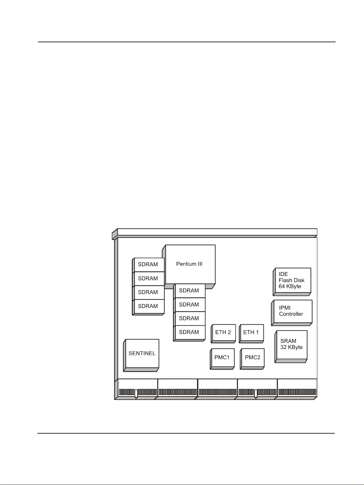
Introduction Features
Features
The PENT/CPCI-735R2/736R2 Family is a universal board using Force
Computers’ SENTINEL universal bridge technology. As it is based on an
Intel Mobile Processor-M of 800 MHz and higher, the PENT/CPCI735R2/736R2 Family offers high performance. Combined with full hotswap capabilities the PENT/CPCI-735R2/736R2 Family is an ideal component for multi-node processor systems.
Other important improvements of the PENT/CPCI-735R2/736R2 Family
are:
• Assembly variants with either two 100BaseT Ethernet controllers at the
front or at the rear or via CompactPCI connector (PICMG 2.16 or RTB)
• More memory: Up to 2 GBytes SDRAM in a single CompactPCI slot
• One 64-bit/66 MHz PMC interface
• IPMI (Intelligent Platform Management Interface) support
• IDE flash disk (assembly option)
Figure 1: Function Blocks
PENT/CPCI-735R2/736R2 Family 1 - 3
Page 34

Variants Introduction
Variants
The PENT/CPCI-735R2/736R2 Family comes in three main assembly variants:
Name Description
CPCI-735R2 PMC slots 1 (64 bit) and 2 (32 bit) accessible,
assembly option for hard disk,
RTB required for two Ethernet interfaces at CompactPCI connector J5
CPCI-735AR2 P M C slo t 1 (64 bi t) ac c e ssi ble ,
assembly option for hard disk,
two Ethernet inte rfaces at front panel,
transformers for Ethernet ports
1)
CPCI-736R2 PMC slots 1 (64 bit) and 2 (32 bit)
assembly option for hard disk,
Ethernet interfaces at CompactPCI connector J3 (PICMG 2.16)
accessible,
1) PMC slot 2 is not compliant to the PMC Specification since the transformer necessary for
PICMG support 2.16 is assembled under the I/O connectors of the PMC module. Only PMC
modules where thi s connector is not assembled and which have front I/O ac cess can be
used.
1 - 4 PENT/CPCI-735R2/736R2 Family
Page 35

Introduction Standard Compliances
Standard Compliances
The PENT/CPCI-735R2/736R2 Family meets the following standards:
Note: EN 55022 Class A and FCC Part 15 Class A are achieved by using
single-point grounding. If you ground the boar d at multiple poin ts, EMC
problems may occur.
Table 1: Standard Compliance
Standard Description
EN 60950
UL/cUL 60950
(predefined Force Computers system)
EN 61000-6-2
EN55022
EN55024
FCC Part 15 Class A
ANSI/IPC-A610 Rev.C Class 2
ANSI/IPC-7711
ANSI/IPC-7721
ANSI-J-001...003
Legal safety requirements
EMC requirements on system level
Manufacturing requirements
PENT/CPCI-735R2/736R2 Family 1 - 5
Page 36

Ordering Information Introduction
Ordering Information
When ordering the PENT/CPCI-735R2/736R2 Family board variants,
upgrades and accessories, use the order numbers given below.
Product Nomenclature
In the following you find the key for the product name extensions.
PENT/CPCI-735R2/736R2 Family/xxxx-ccc-Lyyy-zz
xxxx DRAM size in MByte
ccc Processor type and clock frequency in MHz
Lyyy L2 cache capacity in K Byte
zz Flash disk capacity in MByte
Order Numbers
Depending on the PENT/CPCI-735R2/736R2 Family type, the available
upgrades and accessories may differ. Consult your local sales representative to check the possibility of combinations.
Table 2: Ordering Information Excerpt
Order No. PENT/CPCI-... Description
110714 ...735R2/512-800-L512-0 Intel Processor-M, 800 MHz with
512 MByte main memory, 512 KByte 2nd
level cache
110715 ...735AR2/512-800-L512-0 Intel Processor-M, 800 MHz with
512 MByte main memory, 512 KByte 2nd
level cache
110958 ...735AR2/1G-800-L512-0 Intel Processor-M, 800 MHz with 1 GByte
main memory, 512 KByte 2nd level cache
110712 ...736R2/512-800-L512-0 Intel Processor-M, 800 MHz with
512 MByte main memory, 512 KByte 2nd
level cache
111035 ...735R2/1G-800-L512-0 Intel Processor-M, 800 MHz with 1 GByte
main memory, 512 KByte 2nd level cache
1 - 6 PENT/CPCI-735R2/736R2 Family
Page 37

Introduction Ordering Information
Table 2: Ordering Information Excerpt (cont.)
Order No. PENT/CPCI-... Description
111335 ...735R2/512- 1200 -L512 -0 Intel Processor-M, 1.2 GHz with 512 MByte
main memory, 512KByte 2nd level cache
111336 ...735AR2/51 2-1 200- L51 2-0 Inte l Pro cesso r-M , 1.2 GHz with 512 MByte
main memory, 512KByte 2nd level cache
111337 ...736R2/1G-120 0 - L51 2- 0 Intel Processor-M, 1.2GHz with 1 GByte
main memory, 512KByte 2nd level cache
Hardware Accessories
109895 ACC/RTB-735R2 Rear transition board for CPCI-735R2 and
related installation components
109896 ACC/RTB-736R2 Rear transition board for CPCI-736R2 and
related installation components
109374 PENT/MEM-735/1G-ACC-
KIT
110130 PENT/CPCI-7xx/CABLE-
ACCKIT
Software Accessories
105757 PENT/NT-Supp ort-Package Windows NT drivers
Memory module and related installation
components
Split cable for keyboard/mouse, cable for
serial interface
PENT/CPCI-735R2/736R2 Family 1 - 7
Page 38

Ordering Information Introduction
1 - 8 PENT/CPCI-735R2/736R2 Family
Page 39

2
Installation
Page 40

Page 41
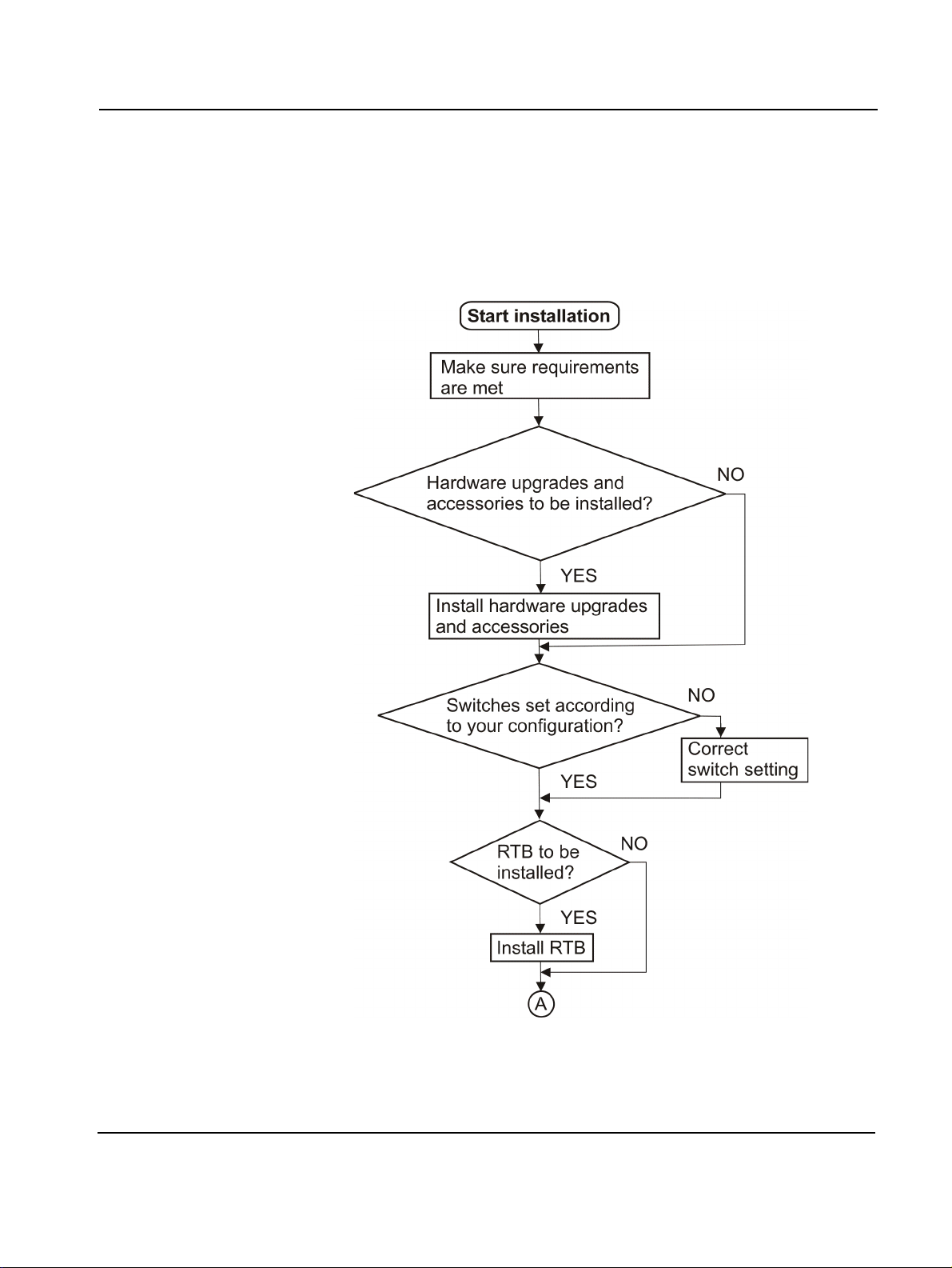
Installation Action Plan
Action Plan
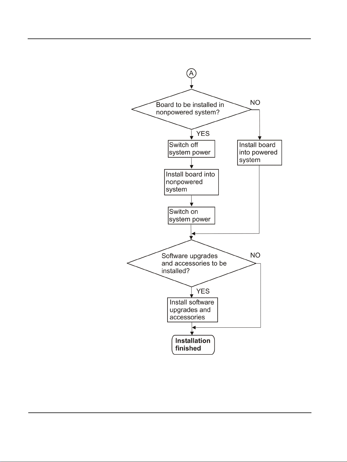
To install the board, the following steps are necessary and described in
detail in the following sections of this chapter.
PENT/CPCI-735R2/736R2 Family 2 - 3
Page 42
Action Plan Installation
2 - 4 PENT/CPCI-735R2/736R2 Family
Page 43

Installation Requirements
Requirements
To meet the environmental requirements, the board has to be tested in the
system where it is to be installed. Before you power up the board, calculate
the power needed according to your combination of board upgrades and
accessories.
Environmental Requirements
The environmental values must be tested and proven in the used system
configuration. The conditions listed below refer to the surroundings of the
board within the user environment.
Note:
• Operating temperatures refer to the temperature of the air circulating
around the board and not to the component temperature.
• Operating temperatures of the 1.2 GHz board variants are lower than
the Force standard temperature requirements. They are limited to
50°C.
Caution Do not operate the board outside the specified environmental limits.
High humidity and condensation may cause short c ircui ts. Make sure t he
board is completely dry and there is no moisture on any surface before
applying power. Do not operate the board below 0°C.
Table 3: Environmental Requirements
Requirement Operating Non-Operating
Temperature
800 MHz variant:
1.2 GHz variant:
Forced air flow 300 LFM –
Temp. change +/– 0.5°C/min +/– 1°C/min
Rel. humidity 5% to 95% non-condensing
0°C to +55°C
0°C to +50°C
(may be further limited by type of
hard disk)
at +40°C
–40°C to +85°C
–40°C to +85°C
5% to 95% non-con den sing
at +40°C
PENT/CPCI-735R2/736R2 Family 2 - 5
Page 44

Requirements Installation
Table 3: Env ironmental Requirements
Requirement Operating Non-Operating
Altitude –300 m to +3,000 m –300 m to +13,000 m
Vibration
10 to 15 Hz
15 to 150 Hz
Shock 5 g/11 ms halfsine 15 g/11 ms halfsine
Free fall 100 mm/3 axis 1,200 mm/all ed ges and
2 mm amplitude
2 g
5 mm amplitude
5 g
corners (packed state)
2 - 6 PENT/CPCI-735R2/736R2 Family
Page 45

Installation Requirements
Power Requirements
The board’s power requirements depend on the installed hardware accessories. The following table gives examples of typical power requirements
for 5V and 3.3V for a processor running at 800 MHz and 1.2 GHz without
any accessories. If you want to install any accessories, the load of the
respective accessory has to be added to the load of the used board variant.
For information on the accessories’ power requirements, refer to the documentation coming with the respective accessory or ask your local Force
Computers representative.
Table 4: Power Requirements
Variant 800 MHz 1.2 GHz
Requirement +5V +3.3V +5V +3.3V
Typical powe r requiremen ts 16 W 6.9 W 23.5 W 7.3 W
Min. voltage +4.85V +3.2V +4.85V +3.2V
Max. voltage +5.25V +3.46V +5.25V +3.46V
Max. current 3.2A 2.1A 4.7A 2.2A
Board in idle state 1.6A 1.4A 1.8A 1.4A
PENT/CPCI-735R2/736R2 Family 2 - 7
Page 46

Hardware Upgrades and Accessories Installation
Hardware Upgrades and Accessories
The PENT/CPCI-735R2/736R2 Family itself allows an easy and cost-efficient way to adapt the board to your application needs.
The following table gives an overview on the possible accessories, described in Table 2 “Ordering Information Excerpt” page 1-6. For the respective board variant, x indicates that the accessory can be used, - indicates
that the accessory cannot be used and a number indicates the available
PMC slot.
Table 5: Possible On-Board Upgrades and Accessories
Variant Mem. Module PMC HD RTB-735R2
CPCI-735R2 x 1+2 x x
CPCI-735AR2 x 1 x x
CPCI-736R2 x 1+2
1)
xx
Memory Module
1) PMC slot 2 is not compliant to the PMC Specification since the transformer necessary for
PIGMIC support 2.16 is assembled under the I/O connectors of the PMC m odule. Only
PMC modules wher e t hi s connector is not asse mbled and which have front I/ O access can
be used.
The following tables gives an overvi ew on the pos sible combinations of the
upgrades and accessories.
Table 6: Possible On-Board Upgrades and Accessories Combinations
Option Mem. Mod. PMC HD
Mem.
Module
PMC PMC: slot 2
HD HD: slot 2
-Mem.: slot 1
PMC: slot 2
1 PMC: slot 1
Mem.: slot 1
Mem.: slot 1
1 PMC: slot 2
HD: slot 2
PMC: slot1
Mem.: slot 1
HD: slot 2
PMC: slot 1
HD: slot 2
-
The memory module PENT/MEM-735 with SDRAM chips provides additional memory for the board. It is connected to the 133 MHz memory bus.
The memory module is available as 1 GByte variant. The maximum possible memory size can be 2 GByte.
For installation information, refer to the PENT/MEM-735 Installation Gu ide.
2 - 8 PENT/CPCI-735R2/736R2 Family
Page 47
Installation Hardware Upgrades and Accessories
PMC Module
All three board variants provide PMC slot 1. It supports e ither a 32- or a 64bit data bus width with a frequency of either 33 MHz or 66 MHz. PMC Slot
1 provides user I/O signals at connector J3.
The CPCI-735R2 and, with limitation, the CPCI-736R2 additionally provides PMC slot 2. It supports a 32-bit data bus width with a maximum frequency of 33 MHz. PMC Slot 2 provides user I/O signals at connector J4.
Both PMC slots provide +/–12V and can be used to in sta ll a stan dard PMC
module.
Note:
• To ensure proper EMC shielding, either operate the board with the
blind panels for the front panel or with the modules installed.
• If the board is upgraded, ensure that the blind panels are stored in a
safe place in order to be used again when removing the upgrades.
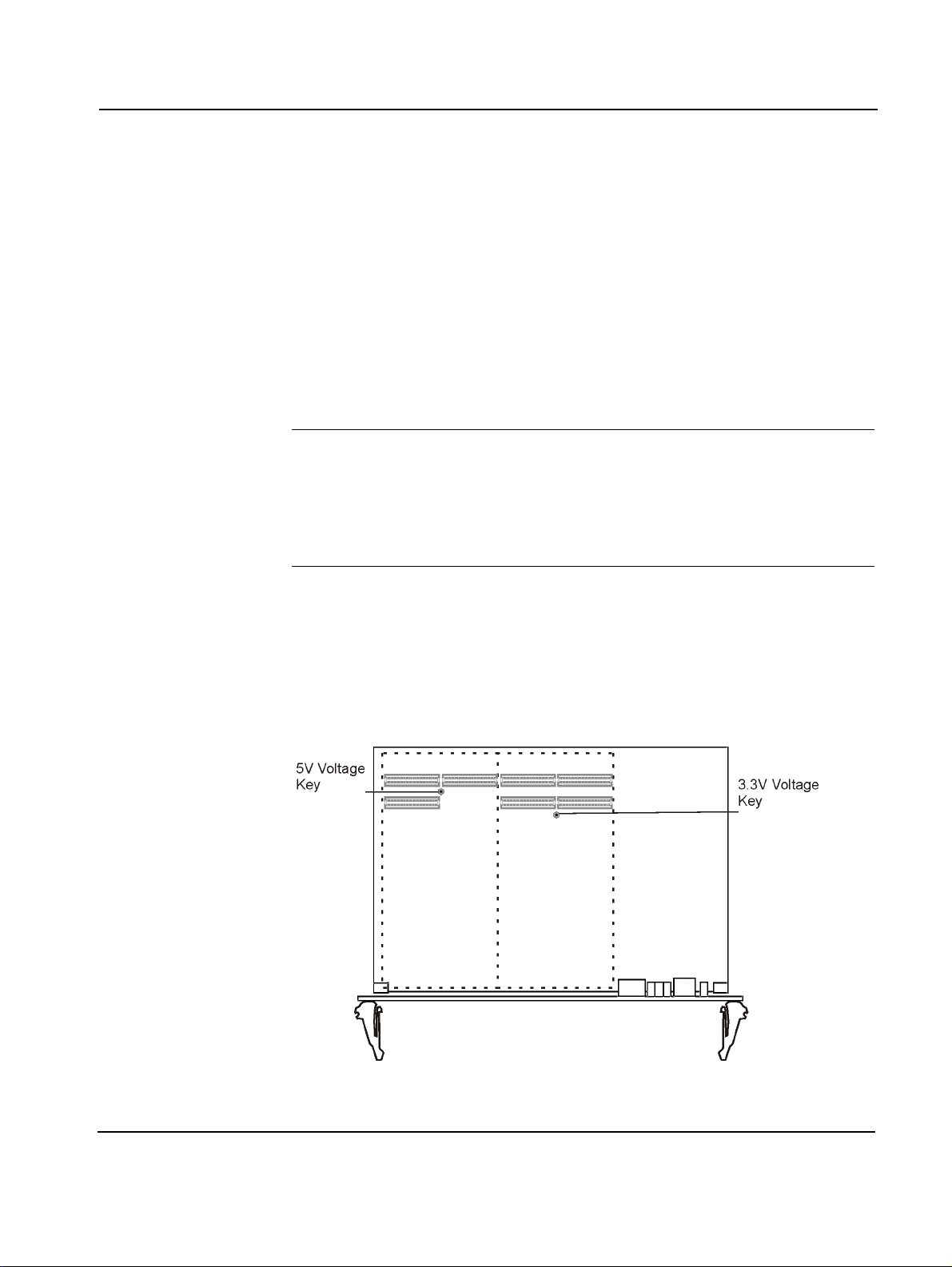
Voltage Key
PMC slot 1 provides a 3.3V PCI interface. Therefore, a voltage key for 3.3V
is assembled at PMC slot 1.
PMC slot 2 provides a 5V-only PCI interface. The voltage key prevents 3.3V
PMC modules from being plugged into PMC slot 2.
Figure 2: Voltage K ey
PENT/CPCI-735R2/736R2 Family 2 - 9
Page 48
Hardware Upgrades and Accessories Installation
Installation Procedure
1. Remove memory module from PMC slot 1 or remove hard disk
from PMC slot 2, if necessary
For removal information, refer to the
and to the CPCI-735/HD-AccKit Installation Guide.
Guide
PENT/MEM-735 Installation
2. Remove blind panel of respective PMC slot from front panel
3. Store blind panel in a safe place
Caution The max. power consumption per PMC slot at +/–12V, 5V and 3.3V level
must not exceed 7.5W (total overall used voltages).
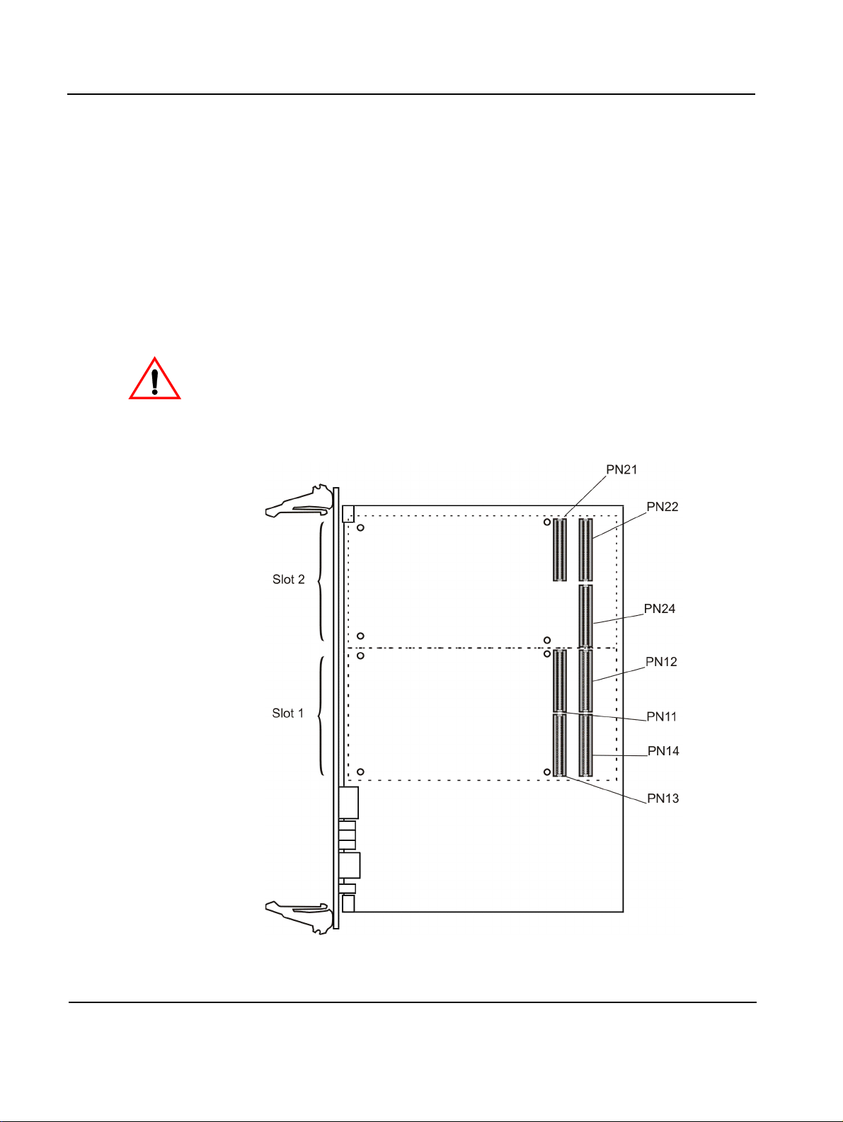
4. Plug PMC module into connectors of PMC slot 1 (PN11, 12, 13, 14)
or PMC slot 2 (PN21, 22 and 24)
Figure 3: PMC Connectors and Slots
2 - 10 PENT/CPCI-735R2/736R2 Family
Page 49
Installation Hardware Upgrades and Accessories
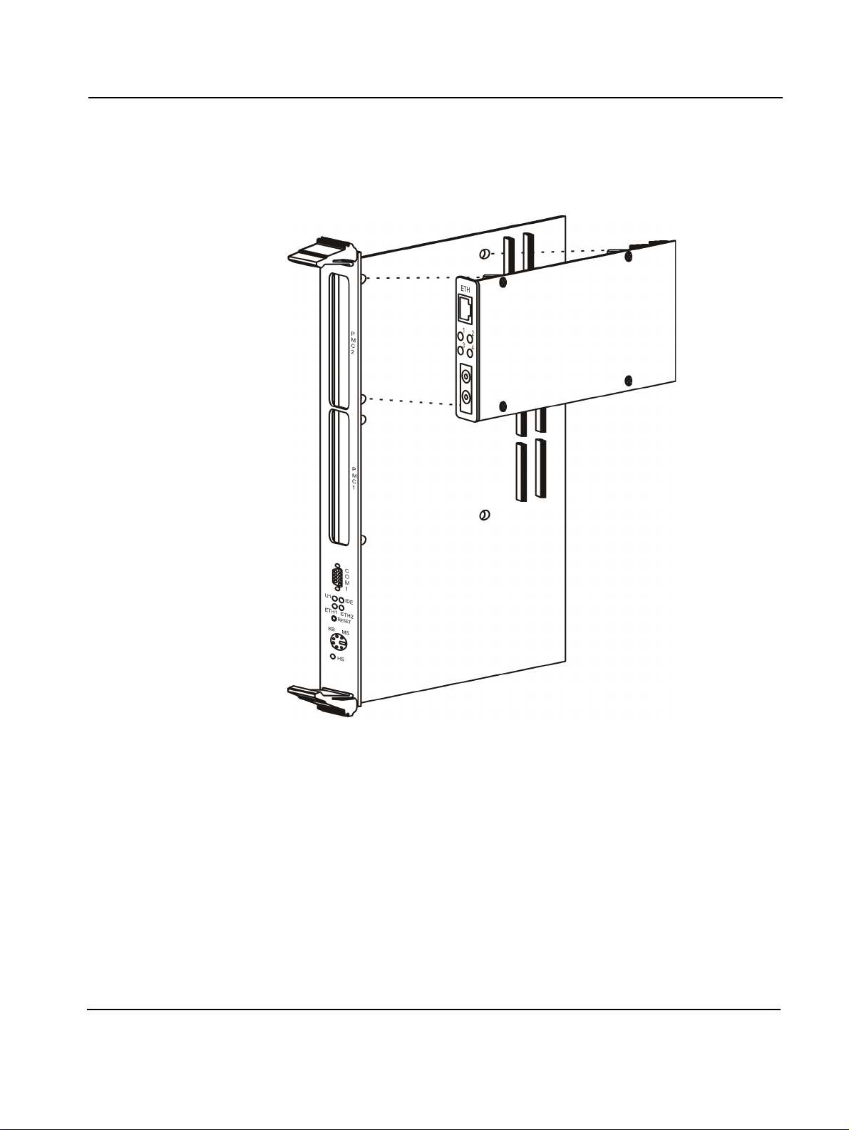
5. Check whether the standoffs of the module cover the mounting
holes of the board
Removal Procedure
Figure 4: Position of Mount ing Holes
6. Place screws delivered with PMC module into mounting holes
7. Fasten screws
1. Remove screws
2. Disconnect PMC module carefully from slot
3. Close front panel gap at free slot with blind panel
PENT/CPCI-735R2/736R2 Family 2 - 11
Page 50
Hardware Upgrades and Accessories Installation
IDE Devices
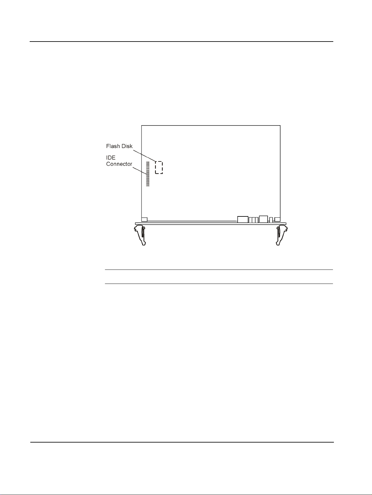
It is possible to have up to two IDE devices on the board which are connected to the primary IDE interface:
• As assembly option a flash disk can be installed
• A hard disk can be connected via on-board connector
Figure 5: Flash Disk and IDE Connector
Note: Never connect more than two devices t o the primar y IDE interf ace.
If only one device is connected to the primary IDE interface, it must be the
master. If two devices are connected, one must be the master, the other one
must be the slave. The flash disk can be configured as IDE master (device 0)
or IDE slave (device 1) via switch SW2-2 (see Table 7 “Default Settings”
page 2-15).
Further devices can be connected to the secondary IDE interface via a rear
transition board. For further information, refer to the ACC/RTB-735 Installa-
tion Guide.
At the first boot after connecting an IDE device use the appropriate menu in
setup to modify the BIOS parameters appropriately (see “Selecting The
Boot Device” page 4-5).
2 - 12 PENT/CPCI-735R2/736R2 Family
Page 51

Installation Hardware Upgrades and Accessories
Hard-Disk Drive Accessory Kit
The Force Computers’ hard-disk accessory kit CPCI-735/HD-AccKit provides a local mass storage device. It can be connected to the primary IDE
port via the on-board connector.
For installation information, refer to the CPCI-735/HD-AccKit Installation
Guide.
Caution If the standard CPCI-735/HD-AccKit is installed, the operating and stor-
age temperature of the board is limited by the maximum operating and
storage temperature of the hard disk. I f the maximum temperat ure of the
hard disk is lower than the one of the board, the maximum temperature
specified for the hard disk must not be exceeded. For information on the
allowed hard-disk operating temperature, consult the CPCI-735/HD-Acc-
Kit Installation Guide.
PENT/CPCI-735R2/736R2 Family 2 - 13
Page 52

Hardware Upgrades and Accessories Installation
Rear Transition Board
As a separate price list item, a rear transition board, the ACC/RTB735R2/736R2, is offered. The RTB provides acc ess to th e C PU board’s CompactPCI user I/O interfaces via industry standard connectors. In addition
to the IPMI specification, IPMB1 and ICMB are ava ilable at the CPU board’s
J5 connector. They can be accessed only via the RTB’s IPMB1 and ICMB
connectors.
In order to use the ICMB support of IPMI, you need the RTB for connecting
the BMCs of two or more chassis.
For further information, refer to IPMI Reference Guide or to the ACC/RTB-
735R2/736R2 Installation Guide.
Note: Only use the ACC/RTB-735R2/736R2 for boards of the PENT/CPCI-735R2/736R2 Family.
2 - 14 PENT/CPCI-735R2/736R2 Family
Page 53
Installation Switch Settings
Switch Settings
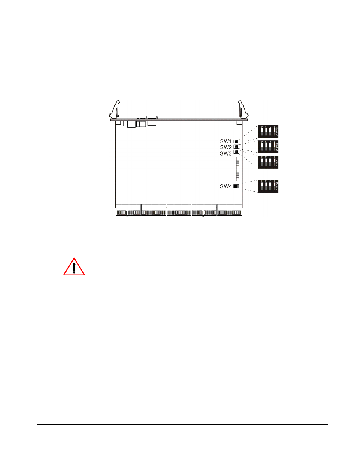
The board provides four configuration switches, SW1,SW2, SW3 and SW4.
Figure 6: Location of Switches
The board is delivered with the white switches set to the default position.
Caution • If the board is to be used in a Force Computers’ system, check
whether the System’s Guide contains information on system-specific
switch settings of the board.
• Do not change swi t ch settin g of switches marked as ‘reserved’ for
they might carry production-related functions which could cause the
board to malfunction.
• In order to prevent damage to the boot block do not change the flash
memory boot block write protec tion unless it is explicitly stated.
• To prevent da mage to the bo ard, do not change switch settings while
the board is operating.
PENT/CPCI-735R2/736R2 Family 2 - 15
Page 54
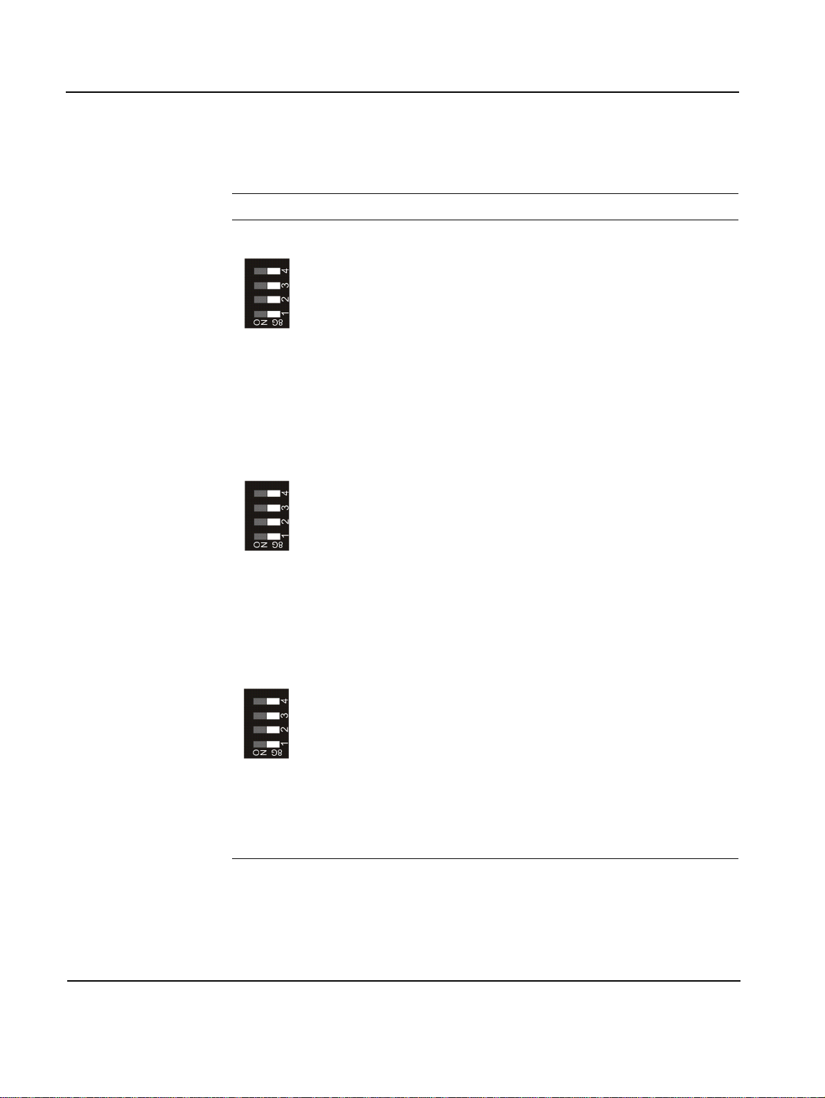
Table 7: Default Settings
Switch Number Description
SW1
1 BIOS crisis recovery (BIOS update)
OFF: Normal operation mode (default)
ON: BIOS crisis recovery mode
2 BIOS Flash memory boot block write protection
OFF: Write-protected (default)
ON: Write enabled
3 Reserved
OFF: Default
4 Reserved
OFF: Default
SW2
1 Reserved
OFF: Default
Installation
1)
2 Reserved
3 Reserved
4FORCE_PM
SW3
1 Reserved
2 Reserved
3PMC1 frequency
4 Reserved
OFF: Default
OFF: Default
OFF: IPMI controller in automatic mod e (de fau lt )
ON: IPMI controller acts as PM
OFF: Default
OFF: Default
OFF: Set by PMC module (default)
ON: Set to 33 MHz
OFF: Default
2)
2 - 16 PENT/CPCI-735R2/736R2 Family
Page 55
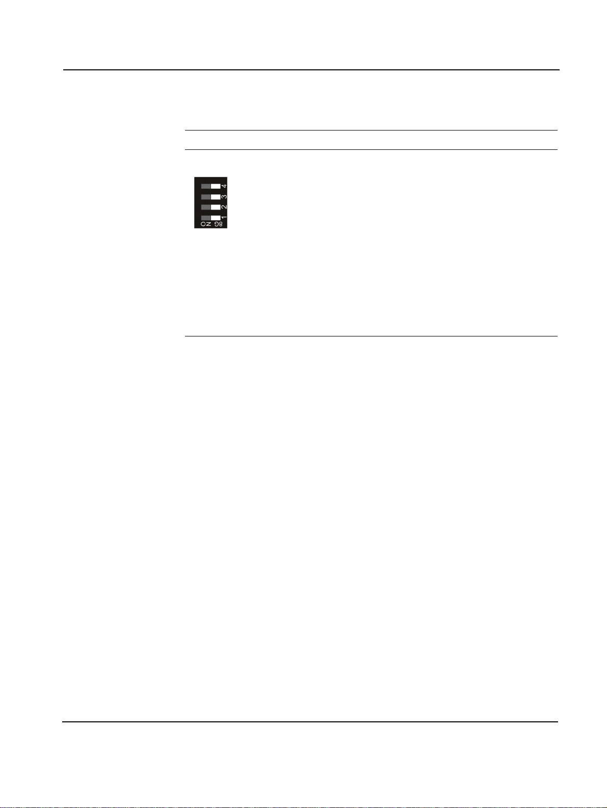
Installation
Table 7: Default Settings
Switch Number Description
SW4
1 Front pa nel reset key
OFF: Reset key enabled (default)
ON: Reset key disabled
2RTB reset key
OFF: Reset key enabled (default)
ON: Reset key disabled
3IPMI reset
OFF: Reset enabled (default)
ON: Reset disabled
4Watchdog
OFF: Enabled (but not started) (default)
ON: Disabled (cannot be started)
1) For further informat ion, refer to the READM E file on the floppy disk for BIOS upgrade
2) The IPMI controller mode depends on whether the board is installed into a CPCI system as
a peripheral or a system b oard:
As system board: BMC
As peripheral board: PM
3) If reset is disabled by switch, register settings have no effect
3)
3)
3)
PENT/CPCI-735R2/736R2 Family 2 - 17
Page 56

Board Installation Installation
Board Installation
The board carries Force Computer’s SENTINEL PCI to CPCI Universal
Bridge. With this technology the board is capable to run as System Controller in the CPCI system slot and as an intelligent I/O board in a peripheral
slot.
The board provides hot-swap support, i.e it may be installe d in or removed
from a powered system. This section is divided into two subsections for installing the board in a non-powered system and in a powered system supporting hot swap.
Note: EN 55022 Class A and FCC Part 15 Class A are achieved by using
single-point grounding. If you ground the CPCI-735R2 at multiple
points, EMC problems may occur.
Installation in a Nonpowered System
Installation Procedure
Caution Before touching integrated circuits, make sure that you are working in an
Due to the hot-swap capability the board has been designed to run in a 5V
Compact PCI System. A 5V key prevents the board from being installed
into an otherwise specified CompactPCI rack.
Note:
• Before installing the board install the upgrades and accessories, if
necessary (refer to “Hardware Upgrades and Accessories” page 2-7).
• If memory modules have been installed, check that a ll s ocket l ocks of
the board are closed before board installation.
1. Turn off system power
ESD-safe environment.
2. Check switch settings for consistency (see “Switch Settings”)
2 - 18 PENT/CPCI-735R2/736R2 Family
Page 57

Installation Board Installation
3. Plug in board depending on intended function either in system
slot marked with a triangle or in peripheral slot marked with a
circle
4. Press handles inwards to lock board on CompactPCI rack
5. Fasten board with screws
6. Plug in interface cables into front panel connectors, if applicable
7. Turn on system power
Removal Procedure
1. Turn off system power
2. Unfasten screws of front panel until board is detached from rack
frame
3. Press handles outwards to disconnect board from backplane
4. Remove board from rails of slot position
Installation in a Powered System
The PENT/CPCI-735R2/736R2 Family supports full hot swap and high
availability.
The basic purpose of hot-swap support and high availability is t o all ow t he
board to be installed and removed in a powered system without adversely
affecting system operation. With hot-swap support, defective boards can be
repaired and systems can be reconfigured without stopping system operation and with minimum operator interaction.
Caution Never remove the board from a system under hot-swap conditi ons unless
a hot-swap or high-availability platform is used and the documentation
of all installed boards and the system documentation explicitly include
appropriate guidelines. For the system hot-swap support of the board in
a system slot, check the system documentation.
The board is fully compliant to CompactPCI Hot Swap Specification PICMG 2.1 R2.0 and can run in a 5V Compact PCI System. A 5V key in connector J1 prevents the board from being installed into an otherwise specified
Compact PCI rack.
PENT/CPCI-735R2/736R2 Family 2 - 19
Page 58

Board Installation Installation
Signals
For information on board status concerning the hot-swap conditions, the
board provides ENUM# and HEALTHY# signals for hot-swap-controller
(HSC) notification and SENTINEL’s Control and Status registers.
After installing the board into or before removing it from a powered system, the interrupt ENUM# signal is generated and passed to the system
board of the CompactPCI system to indicate a service request. The Control
and Status registers allow to determine the source of the ENUM# signal
and to control the hot-swap LED. The HEALTHY# signal is active whenever all backplane and on-board voltages are within their operating range.
Control Elements
The board provides the following elements as man-machine interface:
• Hot-swap switch
Integrated in the lower handle of the front panel, it allows the user to
indicate the intention to remove the board.
Removal Procedure
Caution • Never remove the board from a system under hot-swap conditions
• Blue hot-swap LED
Indicates that you are allowed to remove the board.
Before removing the board, observe the following:
unless a hot-swap or high-availability platform is used and the documentation of all installed boards and the system documentation
explicitly include appropriate guidelines. For the system hot-swap
support of the board in a system slot, check the system documentation.
• Removing the board from a powered system with IDE devices
attached to the board’s secondary IDE interface may result in data
losses.
• Before touching integrated circuits, make sure that you are working
in an ESD-safe environment.
The removal procedure depends on the system the board is to be removed
from.
2 - 20 PENT/CPCI-735R2/736R2 Family
Page 59
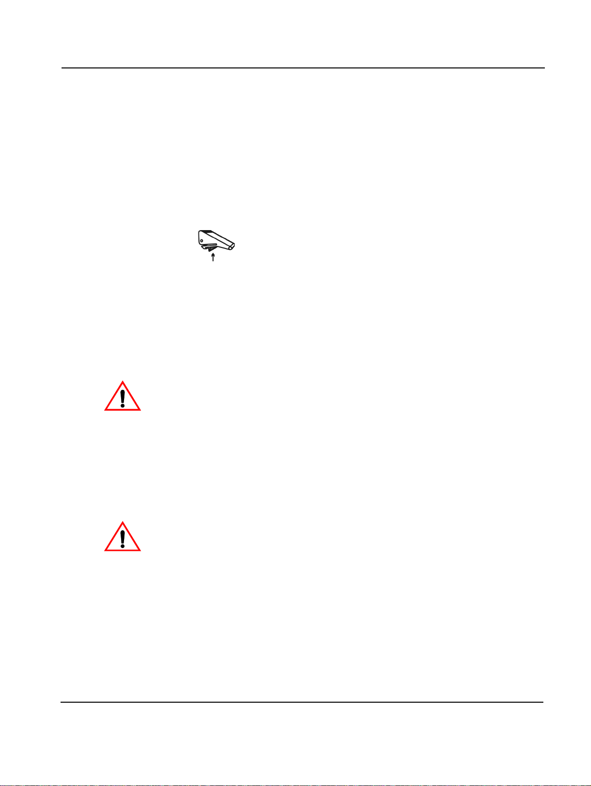
Installation Board Installation
From Basic HotSwap System
From Full Hot-Swap
or High-Availability
System
Caution As long as the hot-swap LED is off, the board is in normal operation and
1. Carry out software disconnection
2. Wait until software disconnection process has been completed
3. Open handles
4. Remove board from powered system
1. Press red button to unlock handles
Figure 7: Button on Handle
2. Open handles
The hot-swap switch will be opened automatically.
3. Wait until blue hot-swap LED is illuminated
must not be removed.
Installation Procedure
Caution • Only install the board under hot-swap conditions if the board i s to be
4. Remove board from powered system
Before installing the PENT/CPCI-735R2/736R2 Family, observe the following:
operated i n slots for w hich hot swap is explic itly permit ted by the
system documentation (in most hot-swap systems peripheral slots
only).
• Installation of the board under hot-swap condi tions is only suppo rted
without IDE devices attached to the board’s secondary IDE interface.
• Before touching integrated circuits, make sure that you are working
in an ESD-safe environment.
PENT/CPCI-735R2/736R2 Family 2 - 21
Page 60

Board Installation Installation
The installation procedure depends upon the system the board is to be installed in.
Into Basic Hot-Swap
System
Into Full Hot-Swap or
High-Availability
System
1. Check board configuration e.g. switch settings, additional memory modules
2. Check that you are using an appropriate rear transition board, if
applicable
3. Insert board into powered system
4. Press handles inwards to lock board on CompactPCI rack
5. Carry out software connection according to system documentation
1. Check board configuration e.g. switch settings, additional memory modules
2. Check that you are using an appropriate rear transition board, if
applicable
3. Insert board into powered system
The hot-swap LED stays blue until the board goes healthy.
4. Press handles inwards to lock board on CompactPCI rack
2 - 22 PENT/CPCI-735R2/736R2 Family
Page 61

Installation Software Upgrades and Accessories
Software Upgrades and Accessories
The following software upgrades and accessories are offered for the
PENT/CPCI-735R2/736R2 Family.
BIOS Upgrade
From the S.M.A.R.T. server you can download a zip file to create a floppy
disk containing a BIOS upgrade file and upgrade utilities. For information
on how to upgrade your BIOS, refer to the README file provided on your
created BIOS upgrade disk.
NT-Support-Package
With the Pent/NT-Support-Package comes a CD-ROM with Windows NT
drivers e.g. to extend hardware support for Windows NT such as an
Ethernet driver.
For information on how to install the NT-Support-Package, refer to the
README file on the CD-ROM.
PENT/CPCI-735R2/736R2 Family 2 - 23
Page 62

Software Upgrades and Accessories Installation
2 - 24 PENT/CPCI-735R2/736R2 Family
Page 63

3
Controls, Indicators, and Connectors
Page 64

Page 65
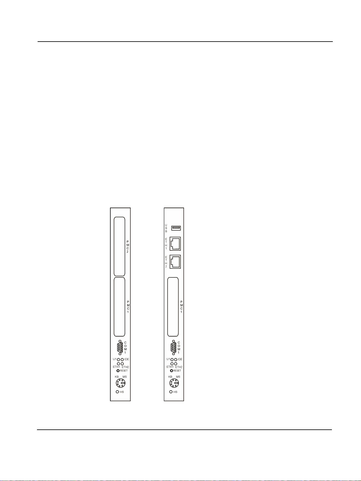
Controls, Indicators, and Connectors Front Panel
Front Panel
Two front panels are available:
• Standard front panel, providing two cutouts for PMC module 1 and 2
• Ethernet front panel, providing:
– Cutout for PMC module 1
– Two connectors for Ethernet 1 and 2
– One USB connector
The standard front panel is used for both, CPCI-7 35R2 and CPCI-73 6R2, the
Ethernet front panel is used for CPCI-735AR2.
The following figure shows the position of cutouts for PMC modules, connectors, LEDs and keys for the standard front panel (left) and the Ethernet
front panel variant (right).
Figure 8: Standard and Ethernet Front Panel
PENT/CPCI-735R2/736R2 Family 3 - 3
Page 66
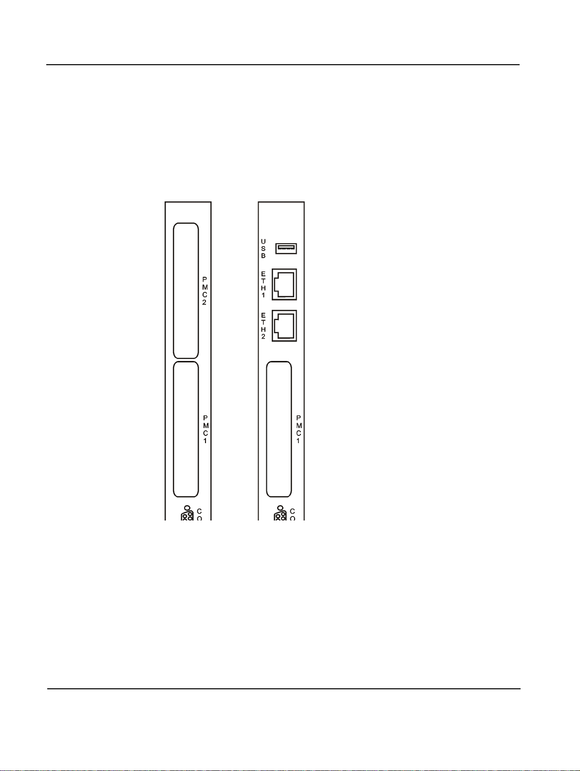
Front Panel Controls, Indicators, and Connectors
PMC Cutouts
The number of PMC cutouts provided depends on the used front panel
variant.
The standard front panel provides two cutouts for PMC module 1 and 2.
The Ethernet front panel provides only one cutout for PMC module 1.
Figure 9: Cutouts for PMC Modules on Standard and Ethernet Front Panel
3 - 4 PENT/CPCI-735R2/736R2 Family
Page 67
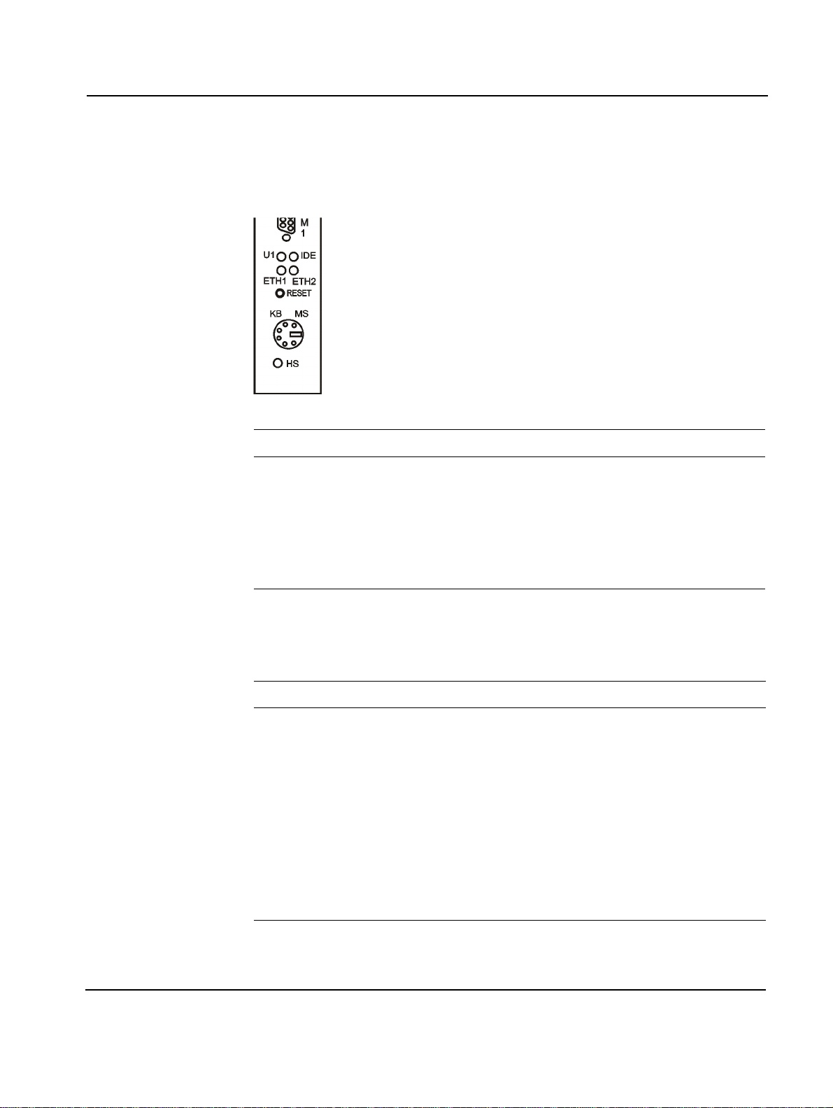
Controls, Indicators, and Connectors Front Panel
LEDs
The following LEDs are provided on both front panel variants:
Table 8: Description of Front Panel LEDs
LED Description
1)
U1
IDE
ETH1
ETH2
1)
1)
1)
User LED: Indicates POST status (green after POST)
User LED: Indicates POST status and IDE activity (green)
User LED: Indicates link/activity of Ethernet controller 1 (green)
User LED: Indicates link/activity of Ethernet controller 2 (green)
HS Hot Swap LED: Indicates hot swap status (blue)
1) LED can be fully user defined (gree n , red , off) b y se ttin g t he L ED Con t rol register
During power up, the settings of the LEDs U1 and IDE are as follows:
Table 9: U1 and IDE LEDs During Power Up
State LED Status
Before POST (Initial Register Values) U1 Red
IDE Red
During Boot Block execution U1 Red
IDE OFF
During POST U1 Red/green
IDE Green/red
After POST U1 Green
IDE Green (indicating IDE activity)
1) LED’s colors change alternately
1)
1)
PENT/CPCI-735R2/736R2 Family 3 - 5
Page 68
Front Panel Controls, Indicators, and Connectors
Keys
The only front panel key available by both front panel variants is the
mechanical reset key.
When enabled and toggled, it instantaneously affects the board by generating a main reset. The main reset generates a CompactPCI reset if the board
is assembled in a system slot.
A reset of all on-board I/O devices and the CPU is performed when the reset key is pushed to the active position. Reset is held active until the key is
back in the inactive position, however at least 200 ms are guaranteed by a
local timer.
For information on how to disable the key, Table 7 “Default Settings”
page 2-15.
3 - 6 PENT/CPCI-735R2/736R2 Family
Page 69
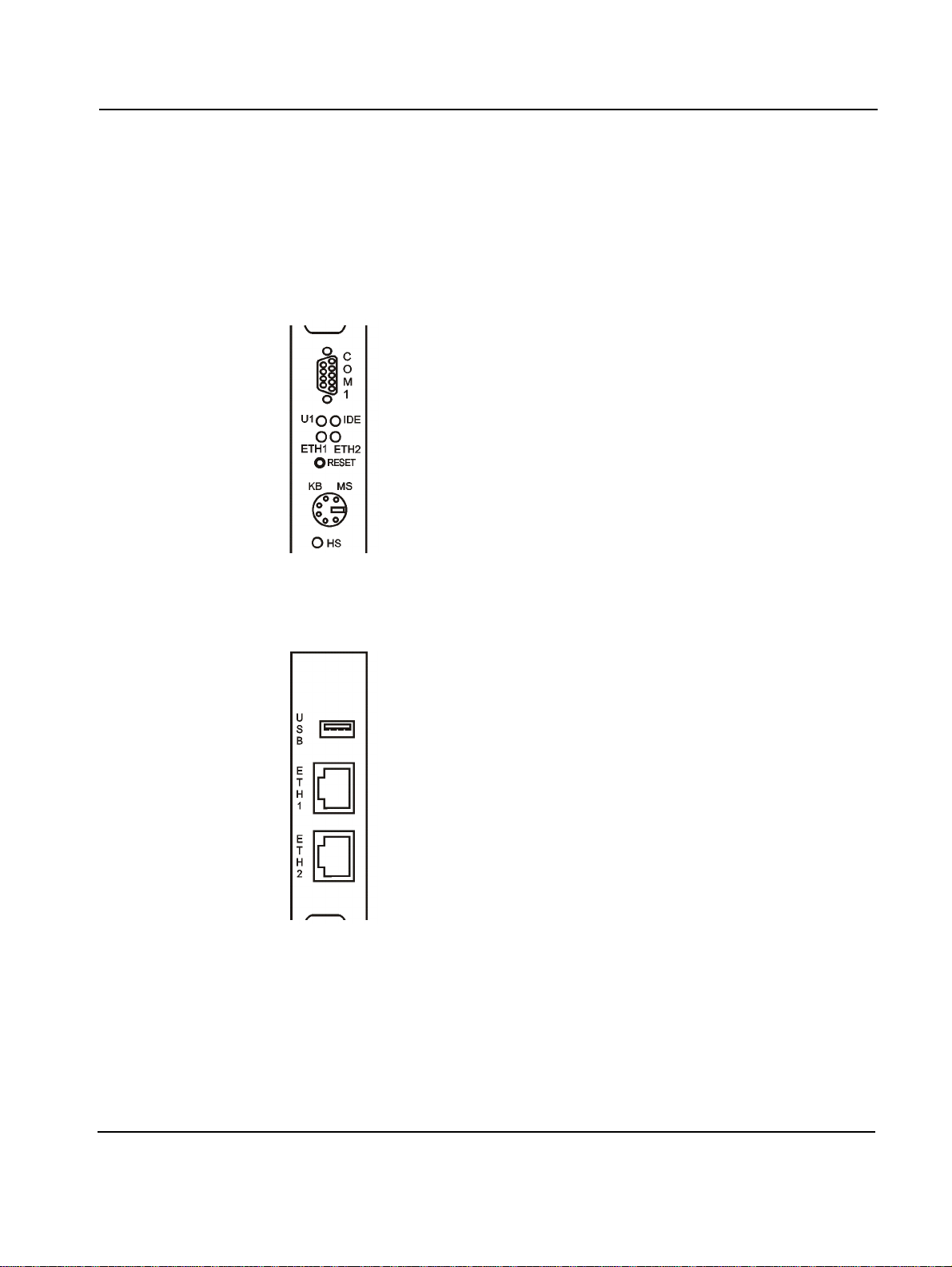
Controls, Indicators, and Connectors Front Panel
Connectors
Both, the standard and the Ethernet front panel provide the following connectors:
• COM1
• Keyboard/Mouse
Figure 10: Connectors of Standard and Ethernet Front Panel
Additionally, the Ethernet front panel provides two RJ-45 connectors for
Ethernet 1 and 2 and one USB connector.
Figure 11: Additional Connectors of Ethernet Front Panel
PENT/CPCI-735R2/736R2 Family 3 - 7
Page 70
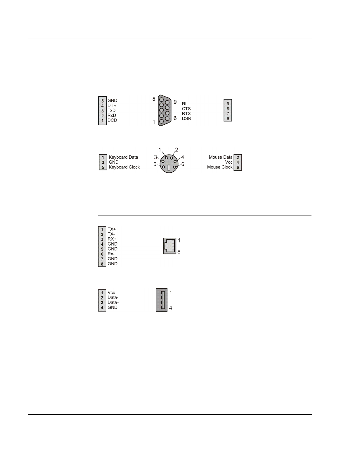
Front Panel Controls, Indicators, and Connectors
If the board is to be incorporated in larger systems and adapted to specific
needs, the following connector pinouts may be useful to give information
on which signal is assigned to which pin.
Figure 12: COM1 Connector Pinout
Figure 13: KBD/MS - Keyboard and Mouse Connector Pinout
Note: Make sure that the length of keyboard and mouse cables does not
exceed three meters.
Figure 14: Ethernet 1 and 2 Connector Pinout
Figure 15: USB Connector Pinout
3 - 8 PENT/CPCI-735R2/736R2 Family
Page 71
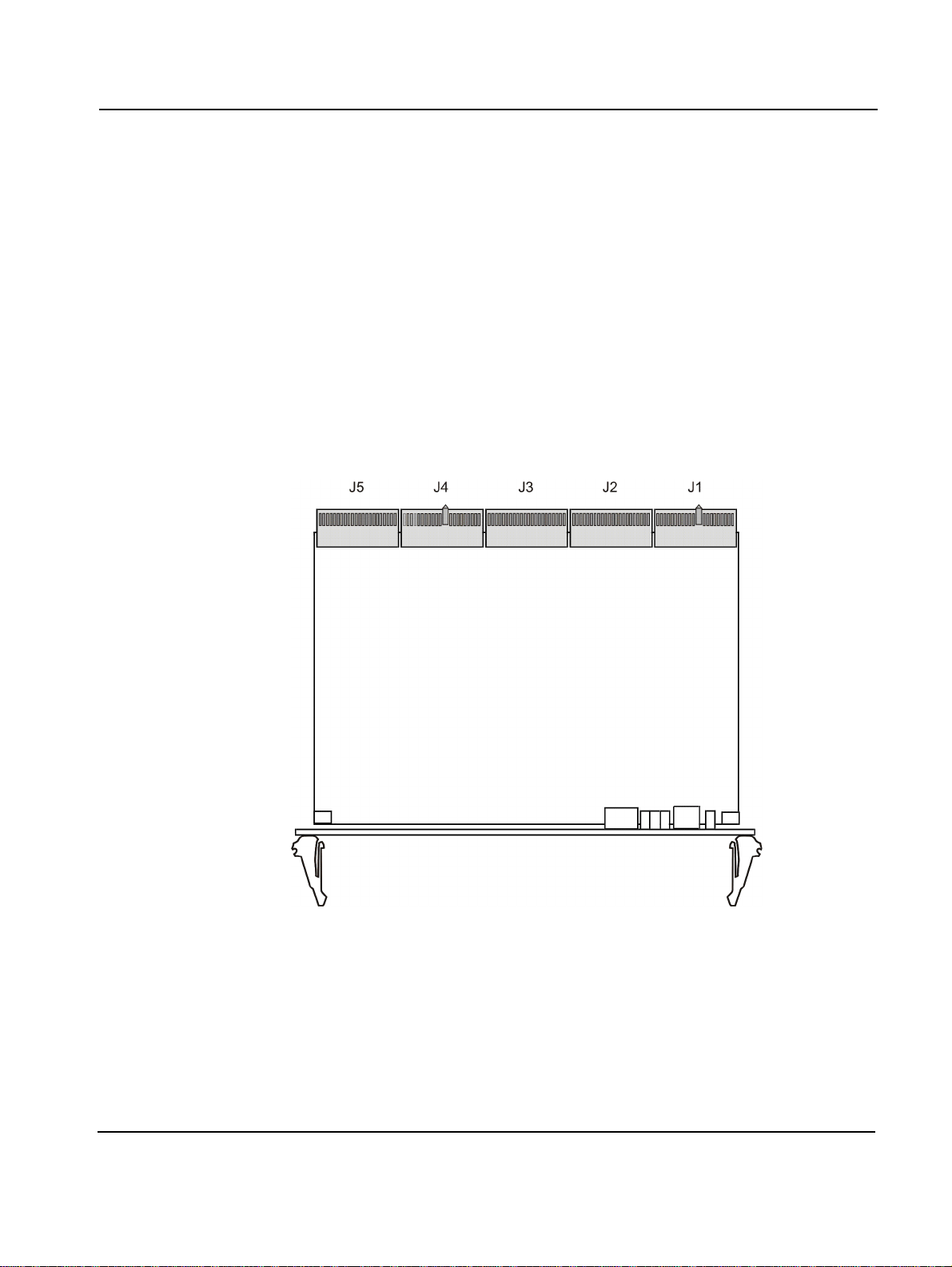
Controls, Indicators and Connectors On-Board Connectors
On-Board Connectors
The following connectors are on-board:
• CompactPCI connectors
• IDE Connector
• PMC connectors
CompactPCI Connectors
The board provides the CompactPCI connectors J1, J2, J3, J4 and J5. The
CompactPCI interface is clocked with 33 MHz and is 32-bit wide.
J1 and J2
Figure 16: Location of CompactPCI Connectors (Top View)
The J1 and J2 connectors implement the CompactPCI 64-bit connector
pinout as specified by the CompactPCI specification PICMG 2.0 R3.0.
Therefore, these pinouts are not documented.
PENT/CPCI-735R2/736R2 Family 3 - 9
Page 72
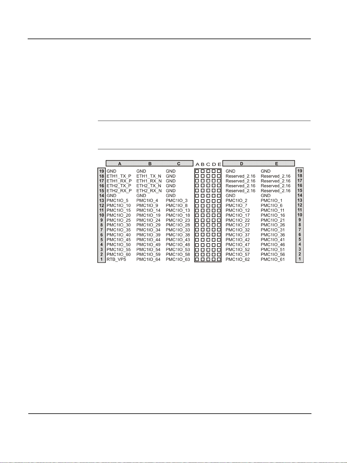
On-Board Connectors Controls, Indicators and Connectors
J3
Connector J3 provides interfaces to:
• Ethernet signals (ETHx, reserved_2.16) for PICMG 2.16 and RTB
• PMC1 I/O (PMC1IO_*)
• Rear transition board information block (RTB_*)
Note: The interface to PICMG 2.16 Ethernet signals is only available on
the CPCI-735R2 and the CPCI-736R2. For CPCI-735AR2 the pins are not
connected.
Figure 17: J3 Connector Pinout
3 - 10 PENT/CPCI-735R2/736R2 Family
Page 73
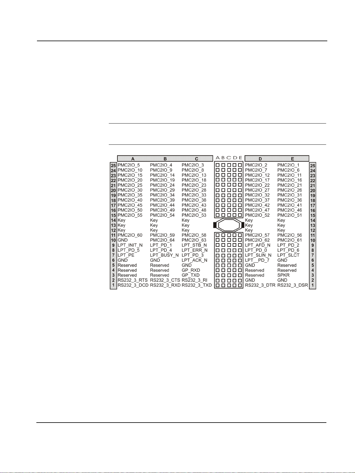
Controls, Indicators and Connectors On-Board Connectors
J4
Connector J4 provides interfaces to:
• Parallel (LPT_*)
• PMC 2 I/O (PMC2IO_*)
• COM3 (RS232_3_*)
Note: The connector J4 is only available on CPCI-735R2 and CPCI735AR2.
Figure 18: J4 Connector Pinout
PENT/CPCI-735R2/736R2 Family 3 - 11
Page 74
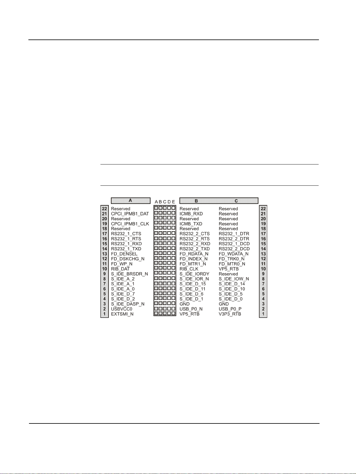
On-Board Connectors Controls, Indicators and Connectors
J5
Connector J5 provides interfaces to:
• Secondary IDE (IDE_*)
• USB (USB_*)
• Keyboard (KBD)
• PS2 mouse (MS)
• COM1 (RS232_1_*) and COM2 (RS232_2_*)
• Floppy (FD_*)
• IPMB and ICMB
Note: Make sure that the length of keyboard, mouse and USB cables
does not exceed three meter.
Figure 19: J5 Connector Pinout, Rows A-C
3 - 12 PENT/CPCI-735R2/736R2 Family
Page 75
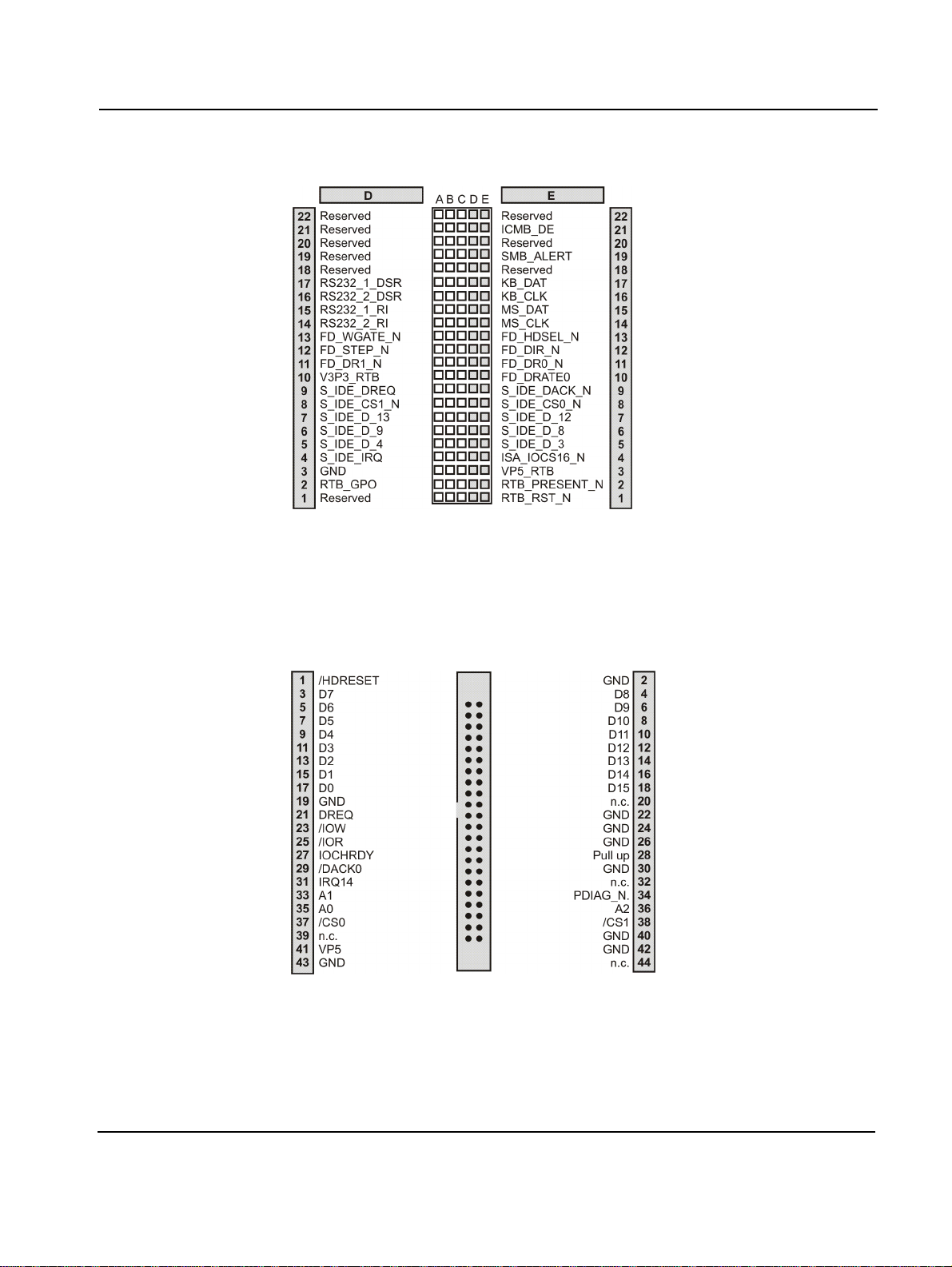
Controls, Indicators and Connectors On-Board Connectors
Figure 20: J5 Connector Pinout, Rows D and E
IDE Connector
A 2.5” hard disk can be connected to the primary IDE interface of the board.
The pinout is given below.
Figure 21: IDE Connector Pinout
PENT/CPCI-735R2/736R2 Family 3 - 13
Page 76
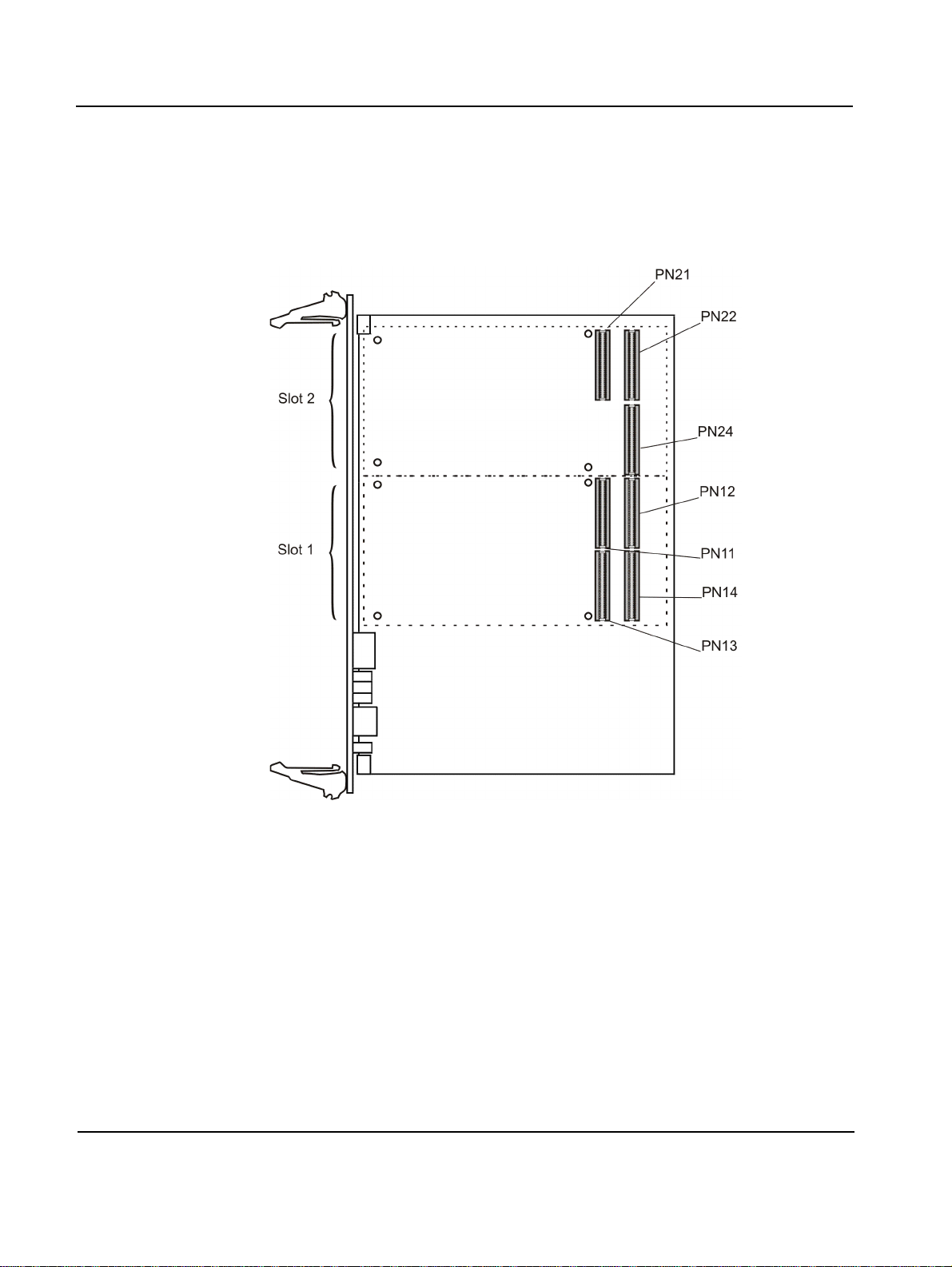
On-Board Connectors Controls, Indicators and Connectors
PMC Connectors
At PMC slot 1, the board provides the connectors PN11-PN14 and at PMC
slot 2, the board provides the connectors PN21, PN22 and PN24.
Figure 22: PMC Connectors and Slots
The connectors PN11-13 and PN21-22 implement the pinout as specified by
the PMC specification IEEE Standard 1386.1-2001. Therefore, these pinouts
are not documented. The following figures show the pinouts for PN14 and
PN24.
3 - 14 PENT/CPCI-735R2/736R2 Family
Page 77
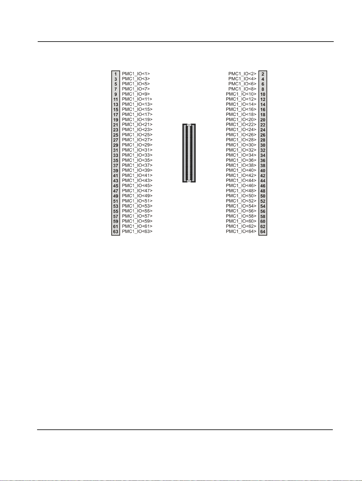
Controls, Indicators and Connectors On-Board Connectors
Figure 23: PN14 Connector Pinout
PENT/CPCI-735R2/736R2 Family 3 - 15
Page 78
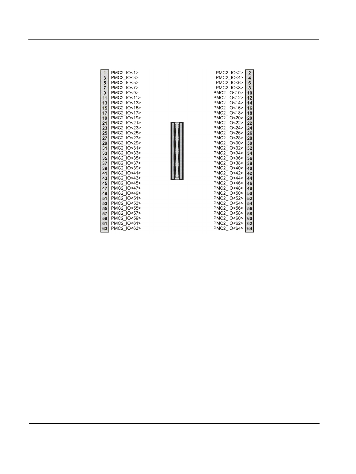
On-Board Connectors Controls, Indicators and Connectors
Figure 24: PN24 Connector Pinout
For information on the signaling level and data b us width of the PMC slots,
refer to section “PMC Module” page 2-9.
3 - 16 PENT/CPCI-735R2/736R2 Family
Page 79

4
BIOS
Page 80

Page 81

BIOS Introduction
Introduction
BIOS (Basic Input Output System) provides an interface between the operating system and the hardware of the board and is used for hardware configuration. Before loading the operating system, BIOS performs basic
hardware tests and prepares the board for the initial boot-up procedure.
BIOS offers the following features:
• Hardware set-up utility for setting configuration data
• Multiboot for a flexible boot order
• Serial Cons ole redirection for remote board con figur ation
• Software upgrade utility
The BIOS complies to the following specifications:
• Plug and Play BIOS Specification 1.0A
• PCI BIOS Specification 2. 1
• SMBIOS Specification 2.3
• BIOS Boot Specification 1.01
• PXE 2.0
The BIOS set-up program is required to configure the hardware of the
board. This configuration is necessary for operating the board and
connected peripherals and is stored in the CMOS memory. A battery
preserves configuration data when the board is powered off.
Whenever you are not sure about configuration settings, restore the default
values. They are provided in case that a value has been changed and one
wishes to reset settings. To restore the default values, press <F9> in setup.
Note:
• Loading the BIOS default values will affect all setup items and will
reset options previously altered.
• If you set the default values, the displayed default values are not yet
stored to be effective for the next boot. They are just loaded to be displayed. However, they become effective if the BIOS setup is exited
after changes have been saved.
PENT/CPCI-735R2/736R2 Family 4 - 3
Page 82
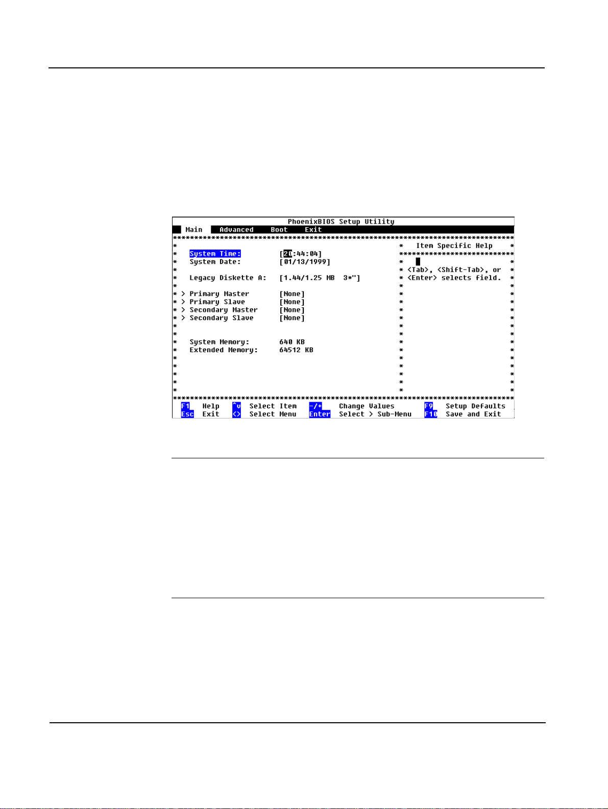
Changing Configuration Settings BIOS
Changing Configuration Settings
When the system is turned on or rebooted, the presence and functionality
of the system components is tested by POST (Power-On Self Test).
Press <F2> while the message Press <F2> to enter SETUP appears on
the screen. The main menu appears.
Figure 25: Main Menu
Note:
• Make sure that BIOS is properly configured prior to ins talling the
operating system and its drivers.
• If you saved changes in setup, the next time the board boots BIOS
will configure the system according to the setup selections stored. If
those values cause the system boot to fail, reboot and enter setup to
get the default values or to change the se lections that caused the failure. If the boot fails or is interrupted three times in a row, the default
values are then loaded automatically.
In order to navigate in setup, use the arrow keys on the keyboard to
highlight items on the menu. All other navigation possibilities are shown at
the bottom of the menu.
Additionally, an item-specific help is displayed on the right side of the
menu window.
4 - 4 PENT/CPCI-735R2/736R2 Family
Page 83
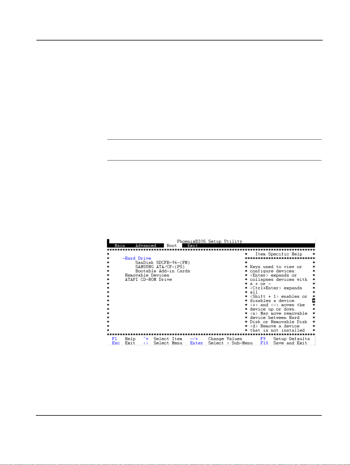
BIOS Selecting The Boot Device
Selecting The Boot Device
There are two possibilities to determine the device from which BIOS
attempts to boot:
• Via setup to select a permanent order of boot devices
• Via boot selection menu to select any device for the next boot-up proce-
dure only
Note: BIOS does not support USB, therefore, booting from USB devices
is not possible.
Via Setup
To determine the order of boot devices in setup, proceed as follows:
1. In menu line, select [Boot]
2. Select order of devices from which BIOS attempts to boot operating system
Figure 26: Boot Device Or der
If BIOS is not successful at booting from a device, it tries to boot from the
first device of the next main entry. If, for example, BIOS cannot boot from
the SanDisk SDCFB-96-(PM), it does not try to boot from the hard disk
PENT/CPCI-735R2/736R2 Family 4 - 5
Page 84
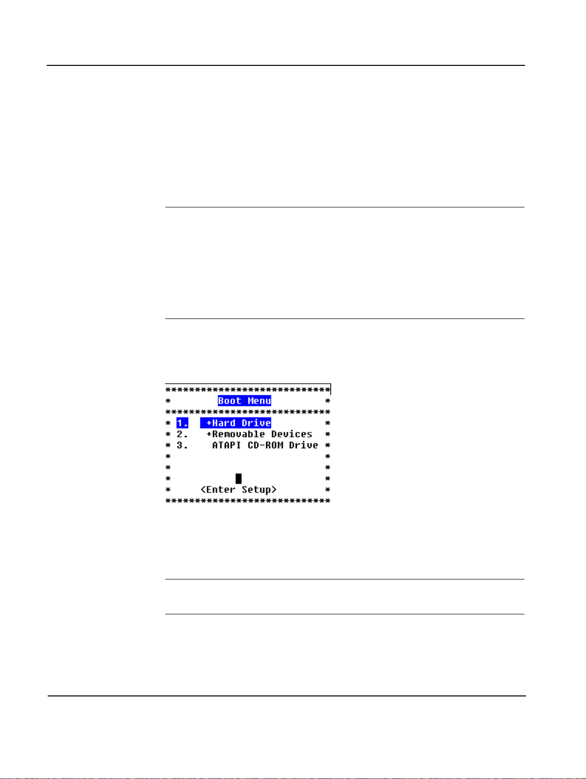
Selecting The Boot Device BIOS
SAMSUNG ATA/CF-(PS) but from the first device listed under
“Removable devices”.
The same options determine the order in wh ich POST installs the devices
and the operating system assigns device letters. BIOS supports up to two
floppy devices to which the operating system may assign, e.g. drive letters
A: and B:. The drives C:, D:, E: etc. are reserved for hard-disk drives.
Note: There is not always an exact correspondence between the order
specified in setup an d the lett ers assigned by the operat ing system. M any
devices, such as legacy option ROMs, support more than one device that
can be assigned to several lett ers. If t he CD-ROM dri ve should have a le tter coming before the one assigned to the hard drive, move it in front of
the hard drive. The group of bootable add-in cards refers to devices with
non-multiboot-compliant BIOS option ROM from which you can boot
the operating system.
Via Boot Selection Menu
To enter the boot menu, press <ESC> during POST.
Figure 27: Boot Menu
Continue with one of the following options:
a) Override existing boot sequence by selecting another boot device from
the boot order list
Note: If the selected device does not load the operating system, BIOS reverts to the previous boot sequence.
b) Select [Enter Setup] to enter setup utility
c) Press <Esc> to return to POST screen and continue with previous boot
sequence
4 - 6 PENT/CPCI-735R2/736R2 Family
Page 85

BIOS Booting the Board via Network
Booting the Board via Network
By default, the possibility to boot the board via network is disabled. This is
done because the boot process takes significantly more time if network boot
is enabled.
In order to enable the possibility to boot from network, proceed as follows:
1. Turn on board
2. Press <F2> when Press <F2> to enter SETUP appears
3. Select [Advanced]
4. Select [POST Options]
5. Set [Network Option ROM] to enabled
6. Save setup
7. Reboot board
Now ETH1 and ETH2 boot devices are displayed in setup and boot
selection menu and can be selected.
PENT/CPCI-735R2/736R2 Family 4 - 7
Page 86

Serial Console Redirection BIOS
Serial Console Redirection
The firmware of the board provides a serial console redirection feature.
This allows remote board configuration by connecting a terminal to the
board via a serial communication link.
The terminal can be connected to display VGA text information. Terminal
keyboard input is redirected and treated as a normal PC keyboard input.
The serial console redirection feature can be configured via setup utility.
Note: If serial console redirection is enabled the terminal represents an
option and is not necessarily required for boot-up procedure.
Requirements
For serial console redirection, the following is required:
• Terminal which supports a VT100 or ANSI mode
• Serial interface cable (part of cable accessory kit available from Force
Computers)
• Null modem adapter
Terminal emulation programs such as TeraTermPro can be used.
Before using TeraTermPro the keyboard configuration of TeraTermPro has
to be modified to guarantee that the function keys work properly. The following function key codes have to be entered into the relevant configuration file:
• PF1=59
• PF2=60
The respective key codes can be found with the keycode.exe utility of the
TeraTerm software package. The required modifications are described in
detail in the TeraTerm help files.
Serial console redirection does not necessarily require a VGA card to be
present. If no VGA card is present, on-board SRAM memory is used as
video buffer.
4 - 8 PENT/CPCI-735R2/736R2 Family
Page 87

BIOS Serial Console Redirection
Remote Configuration
The procedure to configure the board remotely for boot up depends on the
board’s configuration. For boards with standard BIOS the followi ng default
settings for remote configuration are used.
Table 10: Default Settings for Remote Configuration
Parameter Default Setting
Console type VT100
COM port COM1 (on front panel)
Baud rate 9600
Flow control Xon/Xoff
Remote Configuration Set
If the board is set for remote configuration and if you are familiar with the
setting, proceed as follows:
1. Configure terminal to communicate using the same parameters as
in BIOS setup
2. Connect terminal to serial interface cable
3. Connect serial interface cable to COM port you have selected in
setup
4. Turn on board
Remote Configuration Not Set
If the board is not set for remote configuration, proceed as follows:
1. Connect monitor and keyboard to board
2. Turn on board
3. Press <F2> when Press <F2> to enter SETUP appears on
screen
4. Select [Advanced]
5. Select [Console Redirection]
6. Select appropriate parameters for communication
7. Save setup
PENT/CPCI-735R2/736R2 Family 4 - 9
Page 88

Serial Console Redirection BIOS
8. Reboot board
9. Configure terminal to communicate using the same parameters as
in BIOS setup
10.Connect erial interface cable to COM port you have selected in
setup
4 - 10 PENT/CPCI-735R2/736R2 Family
Page 89

BIOS Updating BIOS
Updating BIOS
Via the Software Maintenance And Reference Tools (S.M.A.R.T.) you can
get help on configuration, installation, usage and functionality issues of
Force Computers’ products. You can download documentation via limited
public S.M.A.R.T. access and software via full access after subscribing to a
TSA contra ct.
Downloading Software from S.M.A.R.T.
In order to get access to the S.M.A.R.T. server proceed as follows:
1. Go to Force Computers internet site (www.fci.com)
2. Click on blue button labeled “log on S.M.A.R.T.”
3. Follow the instructions on screen
Update Procedure
For a limited public S.M.A.R.T. account, enter a User ID. A password will
be given to you automatically.
For a full S.M.A.R.T. account, download and subscribe to the TSA contract.
For further information, contact your local sales representative.
To update BIOS, you first have to create a floppy disk containing a BIOS
upgrade file and upgrade utilities. Therefore, download a zip file from the
S.M.A.R.T. server that contains the following files:
• rawrite.exe
• bios_upd.img
• README.1ST
Insert a floppy disk into the drive of your computer and execute rawrite.exe
to write the bios_upd.img file to the disk. This file contains a README file
providing further information for updating your BIOS.
PENT/CPCI-735R2/736R2 Family 4 - 11
Page 90

BIOS Messages BIOS
BIOS Messages
The following messages may be displayed, e.g. if your system fails after
you made changes in the setup menus. If it is not possible to fix a problem
with the help of this section, contact your local sales representative or services for fur t h e r s u p po rt.
Message Explanation Corrective Action
nnnn Cache SRAM Passed nnnn is amount of system
cache in KBytes successfully tested
CD-ROM Drive Identified Autotyping identifi ed CD-
ROM Drive
Diskette drive A error
Diskette drive B error
Drive A: or B: fails the BIOS
POST disk tests. Drive is
selected via setup but either
not present or defect.
Entering SETUP ... Starting setup program None
Extended RAM Failed at
offset: nnnn
nnnn Extended RAM Passed nnnn is amount of RAM in
Extended memory not
working or not configured
properly at offset nnnn
MBytes successfully tested.
None
None
Check that drive is
defined with
proper disk type in
setup, that disk
drive is attached
correctly and that
controller is
enabled.
Check if memory
modules are
installed correctly.
Otherwise contact
your local sales representative or services for further
support.
None
Failing Bits: nnnn nnnn is a map of the bits at
the RAM address (in system, extended or shadow
memory) which failed the
memory test. Each 1 (one) in
the map indicates a failed
bit.
4 - 12 PENT/CPCI-735R2/736R2 Family
Check if memory
modules are
installed correctly.
Otherwise contact
your local sales representative or services for further
support.
Page 91

BIOS BIOS Messages
Message Explanation Corrective Action
Fixed Disk 0 Failure
Fixed Disk 1 Failure
Fixed Disk Controller
Failure
Fixed Disk 0...3 Identified
Incorrect Drive A type run SETUP
Incorrect Drive B type run SETUP
Keyboard controller error Keyboard controller failed
Keyboard error Keyboard not working Check for correct
Keyboard error nnn BIOS discover ed a stuck key
Operating system not
found
Fixed disk not working or
not configured properly
Autotyping identified specified fixed disk.
Type of floppy drive not
correctly identified in setup
test
and displays scan code nn
for stuck key.
Operating system cannot be
located on either driv e A: or
drive C:.
Check if fixed disk
is attached properly. Run setup to
be sure the fixeddisk type is correctly identified.
None
Check for correct
floppy drive in
setup.
Replace keyboard
keyboard connection.
Replace keyboard,
check for stuck
keys.
Enter setup and
check if fixed disk
and drive A: are
properly identified.
Parity Check 1 nnnn Parity error found i n sys-
tem bus. BIOS attempts to
locate address nnnn and display it on screen. If it cannot
locate the address, it displays ????.
Parity Check 2 nnnn Parity error found i n sys-
tem bus. BIOS attempts to
locate address nnnn and display it on the screen. If it
cannot locate the address, it
displays ????.
Press <F1> to resume,
<F2> to Setup
PENT/CPCI-735R2/736R2 Family 4 - 13
Displayed after any recoverable error message
Check for correct
memory module
types.
Check for correct
memory module
types.
Press <F1> to start
boot process or
<F2> to enter setup
and change any settings.
Page 92

BIOS Messages BIOS
Message Explanation Corrective Action
Previous boot incomplete
- Default configuration
used
Real time clock error Real-time clock fails BIOS
Resource allocation conflict on motherboard Run Configuration Utility
Shadow RAM Failed at offset: nnnn
nnnn Shadow RAM Passed nnnn is amount of shadow
System battery is dead Replace and run SETUP
Previous POST did not complete successfully. POST
loads default values and
offers to run setup . I f fa ilure
was caused by incorrect values and they are not corrected, the next boot is li kely
to fail.
test
Possible interrupt or inter-
face resource conflict.
Shadow RAM failed at offset nnnn of the 64k block at
which error was detected.
RAM in KBytes successfully
tested
The SRAM (CMOS) clock
battery indicator shows the
battery is dead
Run setup to
restore original configuration. This
error is cleared the
next time the system is booted.
May require board
repair
Run ISA or EISA
Configuration Utility to resolve
resource conflict.
Contact your local
sales representative or services for
further support.
None
Replace battery and
run Setup to reconfigure system.
System BIOS shadowed System BIOS copied to
shadow RAM
System cache error Cache disabled
System CMOS checksum bad
- run SETUP
RAM cache failed BIOS test.
BIOS disabled cache
System SRAM (CMOS) has
been corrupted or modified
incorrectly, perhaps by an
application program that
changes data stored in
SRAM (CMOS).
None
Contact your local
sales representative or services for
further support.
Run setup and
reconfigure system
either by getting
default values
and/or making
your own selections.
4 - 14 PENT/CPCI-735R2/736R2 Family
Page 93

BIOS BIOS Messages
Message Explanation Corrective Action
System RAM Failed at offset: nnnn
nnnn System RAM Passed nnnn is amount of system
System timer error Timer test failed Requires repair of
UMB upper limit segment
address: nnnn
Video BIOS shadowed Video BIOS successfully
Invalid System Configuration Data – run configuration utility
System RAM failed at offset
nnnn in the 64k block at
which the error was
detected.
RAM in KBytes successfully
tested
Address nnnn of the upper
limit of upper memory
blocks indicates released
segments of BIOS which
may be reclaimed by a virtual memo ry manager
copied to shadow RAM
Check for correct
memory modules.
Otherwise contact
your local sales representative or services for further
support.
None
system board
None
None
Enter setup and use
advanced configuration option to
reset configuration
data (due to corrupted ESCD data).
PENT/CPCI-735R2/736R2 Family 4 - 15
Page 94

BIOS Messages BIOS
4 - 16 PENT/CPCI-735R2/736R2 Family
Page 95

5
Buses
Page 96

Page 97
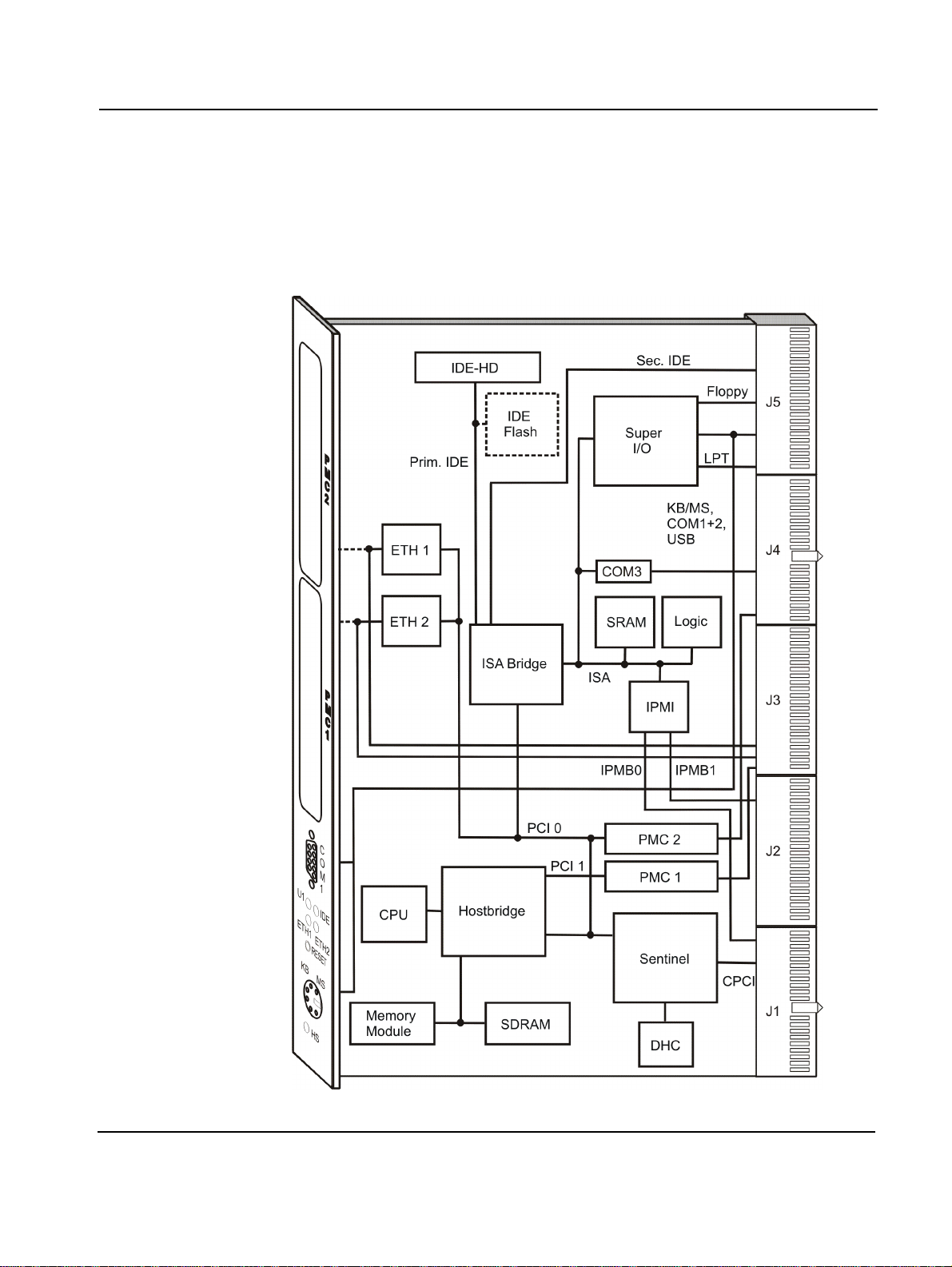
Buses Block Diagram
Block Diagram
The block diagram shows how the CPCI-735R2 devices work together and
which data paths they use. The brok en line marks opti onal devi ces or paths.
PENT/CPCI-735R2/736R2 Family 5 - 3
Page 98

PCI Local Bus 0 Buses
PCI Local Bus 0
PCI local bus 0 is capable to run at 32 Bit and 33 MHz only.
Table 11: Devices on PCI Local Bus 0
PCI Device Device Type IDSEL Dev. No PCI IRQ REQ/GNT
LAN #1 Intel 82559ER AD[17] 1 INTB 0
LAN #2 Intel 82559ER AD[18] 2 INTC 1
Ethernet
PMC Slot 2
(upper)
PCI/CPCIBridge
Primary PCI
Interface
South Bridge OSB4 Open South
PMC2 AD[24] 8 INTA 3
Force Computers
SENTINEL
CNB30LE North
Bridge
Bridge
AD[20] 4 INTA 2
-0 - -
AD[31] 20 - -
The PENT/CPCI-735R2/736R2 Family is equipped with t wo Intel 8 2559ER
10Base-T/100Base-T Ethernet controllers, LAN#1 and LAN#2, which are
able to operate in either full duplex or half duplex mode.
The Ethernet interface is available depending on the variant of the
PENT/CPCI-735R2/736R2 Family board:
Table 12: Ethernet Interface
Board Variant Ethernet Available
CPCI-735R2 Via CompactPCI connector J5 (transformer on rear transition board)
CPCI-735AR2 Via front panel (transformer on CPCI-735AR2)
CPCI-736R2 Via CompactPCI Connector J3 (PICMG 2.16) (transformer on CPCI-
736R2)
Two LEDs at the front panel of the CPCI-735R2, designated as ETH1 and
ETH2, indicate Ethernet link and activity.
5 - 4 PENT/CPCI-735R2/736R2 Family
Page 99

Buses PCI Local Bus 0
PMC2
The PMC 2 interface is a 5V compliant PCI interface with its I/O signals
routed towards CPCI I/O Connector J4.
Note: The space of the PMC 2 I/O connector is used for the Ethernet
transformers to support PICMG 2.16 on CPCI-736R2 boards. Therefore,
the PMC 2 Interface on CPCI-736R2 boards doe s not fully comply to PM C
specifications and can only carry PMC modules without PMC I/O connector assembled.
SENTINEL
Force Computers SENTINEL is used as PCI-to-CompactPCI universal
bridge that enables the board to work as either CompactPCI system (host)
or peripheral board.
SENTINEL is capable to run in either 3.3V or 5V VIO environment. However, hot-swap requirements for the 3.3V environment differ from requirements for the 5V environment. The PENT/CPCI-735R2/736R2 Family
boards are designed for 5V CompactPCI systems only. For further information, refer to “Installation in a Powered System” page 2-19.
The table below lists all fields in the SPROM of the SENTINEL, the contents
loaded into the registers at power up.
Note: Invalid SPROM contents may cause malfunction of the board.
Table 13: SENTINEL SPROM Contents
Register Name Offset Configurable Default Value Comment
Magic word 0
Downstream IR
mask
Upstream IR
mask
16
2
16
6
16
No 1146
No FFFF
No FFFF
16
16
16
-
-
-
PENT/CPCI-735R2/736R2 Family 5 - 5
Page 100

PCI Local Bus 0 Buses
Table 13: SENTINEL SPROM Contents (cont.)
Register Name Offset Configurable Default Value Comment
Downstream BAR
0 DSR setup
8
16
Yes FFFFF000
Maps 4 KByte DSR reg-
16
isters by default.
Larger values provide
access to on-board
resources. A value less
than FFFFF000 is not
allowed.
Downstream BAR
C
16
Yes 00000000
16
-
0 DSR translate
Downstream BAR
2 DSR setup
10
16
Yes FFF00000
This defines a default
16
PCI window of
1MByte.
Downstream BAR
14
16
Yes 00000000
16
-
2 DSR translate
Downstream BAR
18
16
Yes 00000000
16
-
3 DSR setup
Downstream BAR
3 DSR translate
Downstream BAR
1C
20
16
16
Yes 00000000
Yes 00000000
16
16
-
-
4 DSR setup
Downstream BAR
24
16
Yes 00000000
16
-
4 DSR translate
Upstream BAR 2
DSR setup
Upstream BAR 2
28
2C
16
Yes FFF8000016 Defines a default PCI
window of 512 KByte.
16
Yes 00000000
16
-
DSR translate
Memory base pre-
load
30
16
No 0001
16
These two settings
effectively disable the
memory window
(base>limit).
Memory limit
32
16
No 0000
16
-
preload
I
O outbound
2
34
16
No FFFFFFFF
16
post list interr u pt
mask
Subsystem ven-
38
16
No 1146
16
dor ID preload
5 - 6 PENT/CPCI-735R2/736R2 Family
 Loading...