

Page 1

OPERATION
MANUAL
USF-212S
Universal System Frame
USF-212PS
Power Supply Unit
2nd Edition
Page 2
Precautions
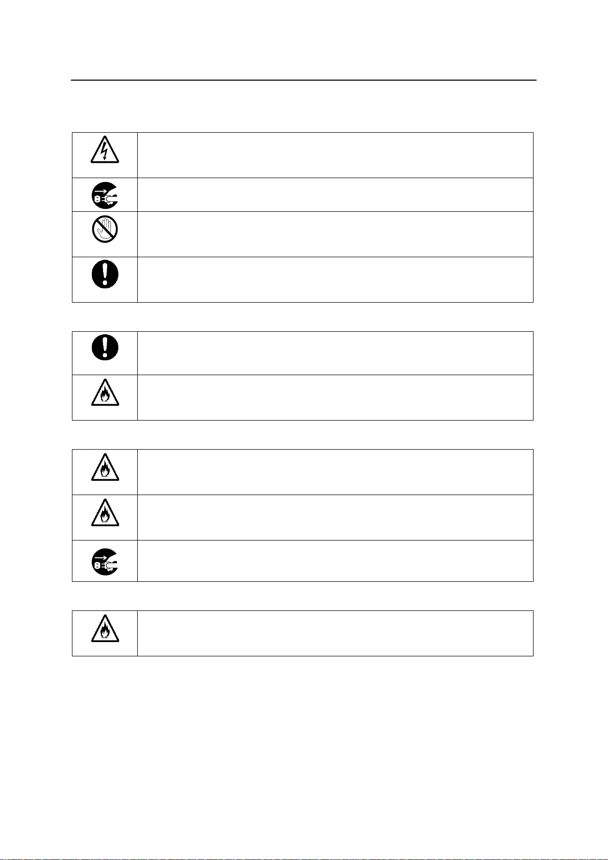
Caution
Operate unit only at the specified supply voltage.
Disconnect the power cord via the power plug only. Do not pull on the cable portion.
Stop
Do not place or drop heavy or sharp-edged objects on the power cord. A damaged
cord can cause fire or electrical shock hazards. Regularly check the power cord for
excessive wear or damage to avoid possible fire / electrical hazards.
Caution
Ensure the power cord is firmly plugged into the AC outlet.
Caution
Ensure the unit is properly grounded at all times to prevent electrical shock.
Hazard
Do not ground the unit to gas lines, units, or fixtures of an explosive or dangerous
nature.
Hazard
Do not operate the unit under hazardous or potentially explosive atmospheric
conditions. Doing so could result in fire, explosion, or other hazardous results.
Hazard
Do not allow liquids, metal pieces, or other foreign materials to enter the unit. Doing so
could result in fire, other hazards, or a unit malfunction.
If a foreign material does enter the unit, turn the power off and immediately disconnect
the power cord. Remove the material and contact an authorized service representative
if damage has occurred.
Hazard
Handle with care to avoid impact shock during transit, which may cause malfunction.
When you need to transport the unit, use the original or suitable alternative packing
material.
Important Safety Warnings
[Power]
[Grounding]
[Operation]
[Transportation]
2
Page 3
[Circuitry Access]
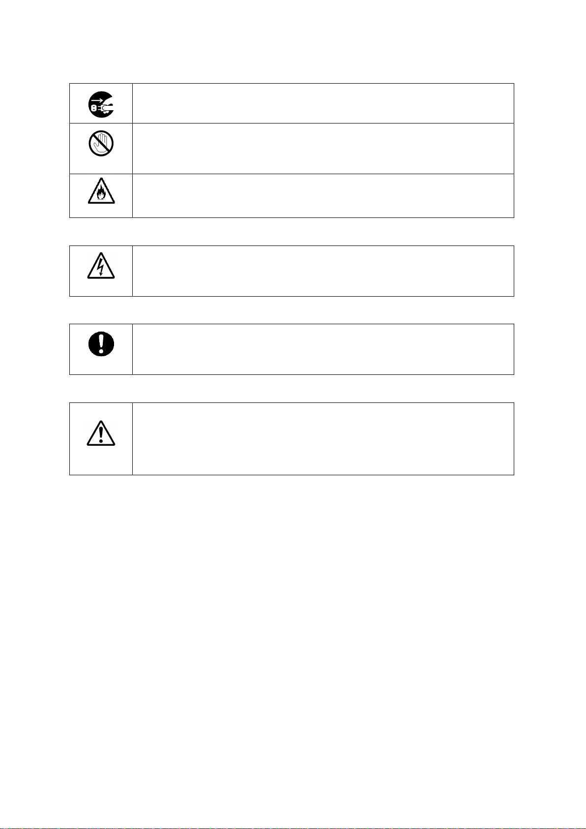
Do not remove covers, panels, casing, or access the circuitry with power applied to the
unit. Turn the power off and disconnect the power cord prior to removal. Internal
servicing / adjustment of unit should only be performed by qualified personnel.
Stop
Do not touch any parts / circuitry with a high heat factor.
Capacitors can retain enough electric charge to cause mild to serious shock, even after
the power has been disconnected. Capacitors associated with the power supply are
especially hazardous.
Hazard
Unit should not be operated or stored with cover, panels, and / or casing removed.
Operating the unit with circuitry exposed could result in electric shock / fire hazards or
a unit malfunction.
Caution
If abnormal odors or noises are noticed coming from the unit, immediately turn the
power off and disconnect the power cord to avoid potentially hazardous conditions. If
problems similar to the above occur, contact an authorized service representative
before attempting to operate the unit again.
Caution
To rack-mount or ground the unit, or to install rubber feet, do not use screws or
materials other than those supplied. Doing so may cause damage to the internal
circuits or components of the unit. If you remove the rubber feet that are attached to the
unit, do not reinsert the screws that secure the rubber feet.
Caution
Consumable items that are used in the unit must be periodically replaced. For further
details on which parts are consumables and when they should be replaced, refer to the
specifications at the end of the Operation Manual. Since the service life of the
consumables varies greatly depending on the environment in which they are used,
such items should be replaced at an early date. For details on replacing consumable
items, contact your dealer.
[Potential Hazards]
[Rack Mount Brackets, Ground Terminal, and Rubber Feet]
[Consumables]
3
Page 4
Upon Receipt
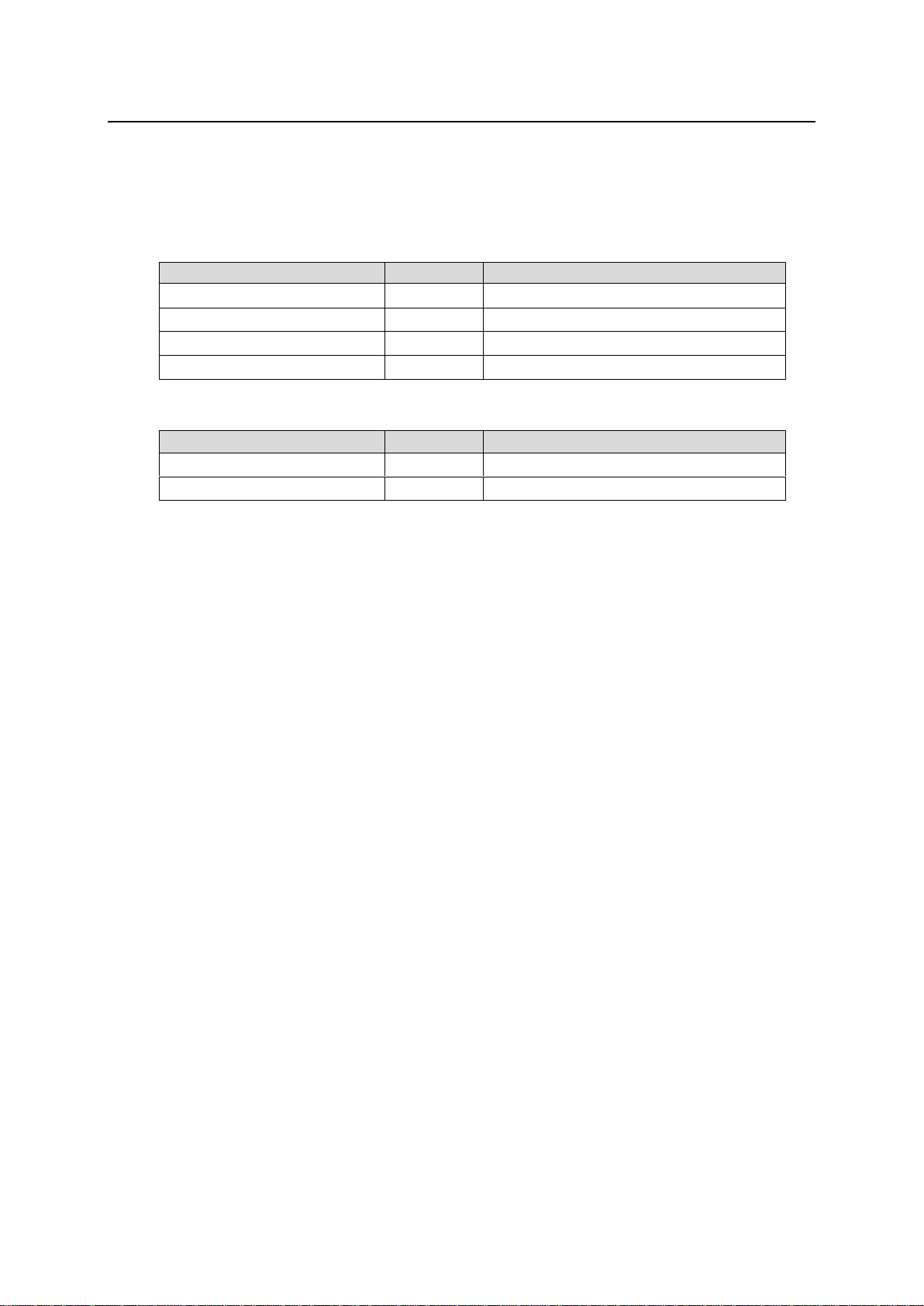
ITEM
QTY
REMARKS
USF-212S
1
AC Cable
1 set
Includes AC Cord Retaining Clip
CD-ROM
1
Operation Manual (PDF)
Set up Guide
1
ITEM
QTY
REMARKS
USF-212PS
1
Redundant Power Supply Unit
AC Cable
1 set
Includes AC Cord Retaining Clip
USF-212S units and their accessories are fully inspected and adjusted prior to shipment. Operation can
be performed immediately upon completing all required connections and operational settings.
Check your received items against the packing lists below. Check to ensure no damage has occurred
during shipment. If damage has occurred, or items are missing, inform your supplier immediately.
USF-212S
USF-212PS Option
4
Page 5

Table of Contents
1. Prior to Starting ..................................................................................................................................... 7
1-1. Overview ..................................................................................................................................... 7
1-2. Features ...................................................................................................................................... 7
1-3. About This Manual ...................................................................................................................... 7
2. Installing AC Cord Retaining Clip ......................................................................................................... 8
3. USF-212S Module List ......................................................................................................................... 9
4. Part Descriptions .................................................................................................................................. 9
4-1. Front Panel .................................................................................................................................. 9
4-2. Opening the Front Panel ...........................................................................................................10
4-3. Detaching the Front Panel ........................................................................................................11
4-4. Front Interior ..............................................................................................................................12
4-5. Slot Number ..............................................................................................................................13
4-6. Power Supply ............................................................................................................................13
4-7. Rear Panel ................................................................................................................................14
4-8. Fan ............................................................................................................................................15
4-9. Internal SDI Bus ........................................................................................................................15
4-10. ALARM Connector ..................................................................................................................16
4-10-1. Example of Alarm Connection .........................................................................................16
5. USF Module Installation .....................................................................................................................17
5-1. Installing of a USF Rear Module ...............................................................................................17
5-2. Installing a USF Front Module ..................................................................................................18
6. Replacing a USF Module....................................................................................................................19
6-1. Removing the Front Module ......................................................................................................19
6-2. Removing the Rear Module ......................................................................................................19
7. Installing or Removing a Power Supply Unit ......................................................................................20
7-1. Installing a Power Supply Unit ..................................................................................................20
7-2. Removing a Power Supply Unit ................................................................................................21
8. Control Module ...................................................................................................................................22
8-1. Internal Control Module Settings ...............................................................................................22
9. Control via Web GUI ...........................................................................................................................23
9-1. Connecting USF-212S to a PC .................................................................................................23
9-1-1. Connecting LAN 1 and LAN 2 Ports ..................................................................................23
9-1-2. LAN A Port .........................................................................................................................24
9-2. PC System Requirements .........................................................................................................24
10. USF-212S Web GUI .........................................................................................................................25
10-1. Status Tab ...............................................................................................................................25
10-2. Alarm Tab ................................................................................................................................27
10-3. Network Tab ............................................................................................................................28
10-4. SNMP Tab ...............................................................................................................................30
10-5. Utility Tab ................................................................................................................................32
11. About SNMP .....................................................................................................................................34
12. Specifications and Dimensions ........................................................................................................36
12-1. Specifications ..........................................................................................................................36
12-1-1. USF-212S ........................................................................................................................36
12-1-2. USF-212PS ......................................................................................................................36
12-2. External Dimensions ...............................................................................................................37
12-2-1. USF-212S ........................................................................................................................37
12-2-2. USF-212PS ......................................................................................................................37
5
Page 6

6 7
Page 7

1. Prior to Starting
1-1. Overview
The USF-212S is a low cost and space saving Universal System Frame that can be freely
configured. Up to 12 modules can be installed into one USF frame.
Dual, redundant power supplies can be configured by adding an optional USF-212PS power unit,
improving operation safety.
An internal switching hub and router allows high speed network communications and flexible
network systems.
1-2. Features
Up to 12 USF modules (boards) can be installed to match your system requirements.
Installing a USF-212PS enables a redundant (dual power supply) configuration.
All modules can be replaced from the front. Power supply units and front USF module units
both support hot-swapping.
Alarm sensors (Fan Stop/ Power Unit Voltage Error/ Temperature Error) and status indicators
(Power/ Fan/ Temperature) are shown on front LEDs.
Alarm data able to output from rear connectors.
Two genlock inputs (BB or Tri-level sync) with loop-through.
(Input reference signal able to be supplied to all frame modules installed in the unit.)
EIA Standard 2RU size.
Monitoring with SNMP available.
High speed connection of each module via internal switching hub.
USF modules can be monitored and controlled via PC web browser.
1-3. About This Manual
This manual is intended to help the user easily operate this product and make full use of its
functions during operation. Before connecting or operating your unit, read this operation manual
thoroughly to ensure you understand the product. Afterwards, store this manual in a safe place for
future reference.
Page 8
2. Installing AC Cord Retaining Clip
1)
2)
2)
4)
3)
5)
6)
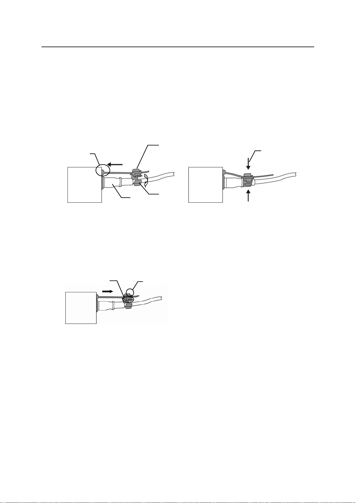
Secure the AC cord with the supplied ladder strap/retaining clip assembly to prevent accidental
disconnection from the USF-212S.
Installing the clip
1) Wrap the retaining clip around the AC cord (with the anchor of the ladder strap toward the unit).
2) Insert the anchor into the hole next to the AC IN socket.
3) Lightly fasten the clip around the AC cord.
4) Plug in the power cord.
5) Slide the clip on the ladder strap toward the plug.
6) Fasten the clip tightly.
7) Gently pull on the AC cord to ensure it is secured.
Unplugging the AC Cord
1) Push the tab on the retaining clip to unfasten the clip.
2) Push the tab on the ladder strap up and slide the clip back.
3) Unplug the AC cord.
8
Page 9
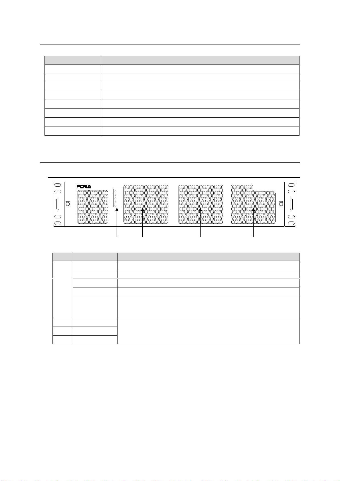
3. USF-212S Module List
Module
Comments
USF-1040VEA
Optional USF-VEAIF is required to set via Web GUI.
USF-1100VEA
Optional USF-VEAIF is required to set via Web GUI.
USF-1053DDA
USF-108ADA
Optional USF-ADAIF is required to set via Web GUI.
USF-1043FS
USF-1043DCC
Remote control requires FA-10DCCRU option.
USF-1013MUX
USF-1013DEMUX
TEMP
FAN
DC 2
DC 1
ALARM
ON
POWER
USF-212
UNIVERSAL SYSTEM FRAME
LOCK LOCK
No.
Name
Description
(1)
POWER ON
This LED lights green when DC power is supplied normally
DC 1
This LED lights red when a voltage error occurs in power module 1.
DC 2
This LED lights red when a voltage error occurs in power module 2.
FAN
This LED lights red when at least one fan has stopped.
TEMP
This LED lights red when a temperature error occurs in the power
supply module(s). Lower the environmental temperature to continue
operation.
(2)
FAN1
Cooling fans. Operation status can be monitored by Web GUI Status
Tab. Refer to Sec.10-1. “Status Tab.”
(3)
FAN2
(4)
FAN3
(1)
(4)
(3)
(2)
4. Part Descriptions
4-1. Front Panel
* DC 1 and DC 2 become functional when a USF-212PS power supply option is installed.
9
Page 10
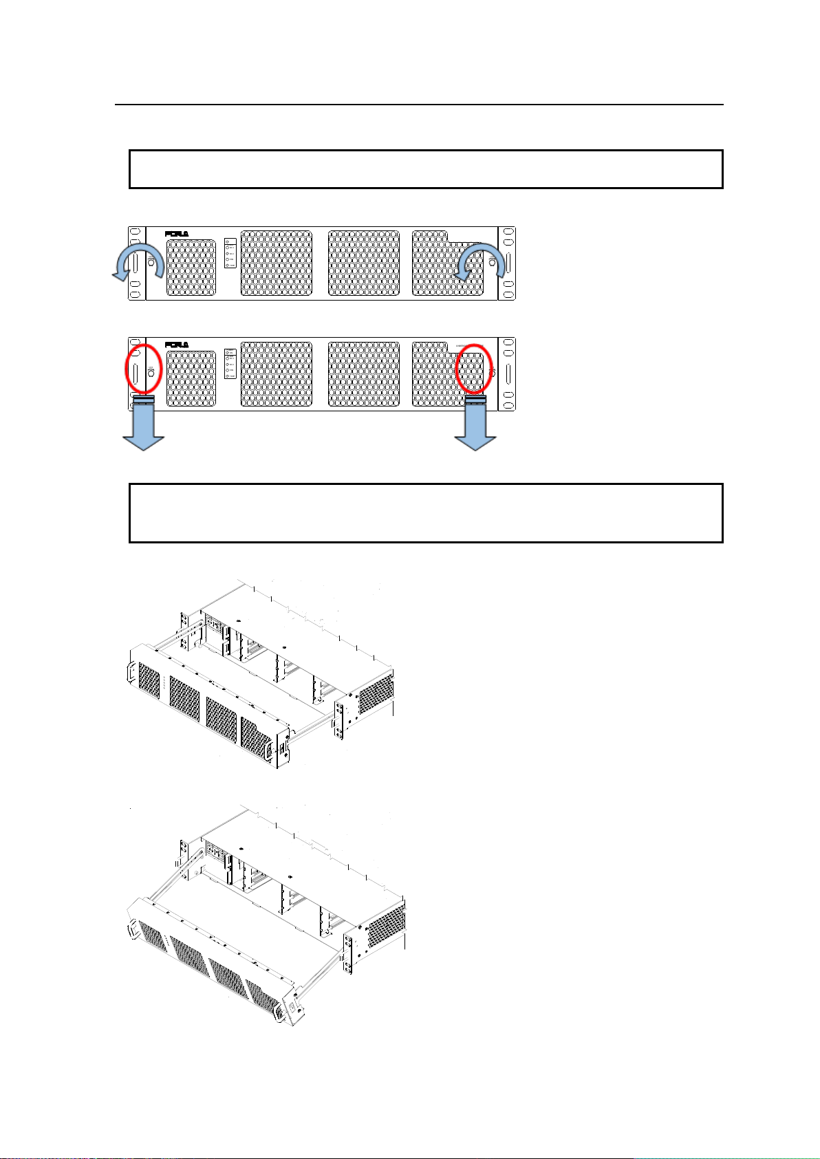
4-2. Opening the Front Panel
IMPORTANT
The front panel may be difficult to open if the USF frame is placed on a desk, and may be
damaged if it is forced to open. Perform the following steps after setting the frame in a rack
TEMP
FAN
DC 2
DC 1
ALARM
ON
POWER
USF-212
UNIVERSAL SYSTEM FRAME
LOCK LOCK
TEMP
FAN
DC 2
DC 1
ALARM
ON
POWER
USF-212
UNIVERSAL SYSTEM FRAME
LOCK LOCK
IMPORTANT
An OPEN alarm sounds intermittently, every 30 seconds, when the front panel is opened.
After 5 minutes, the alarm will sound continuously until the front panel is closed.
In case the power is on, complete the procedure in a short period of time
1. Loosen the two thumbscrews on the front panel by turning them counterclockwise.
2. Pull out the front panel using the pull handles. The fan stops while the front panel is open.
3. Pull out the front panel as shown in the figure below.
4. The front panel rails can be tilted down.
10
Page 11
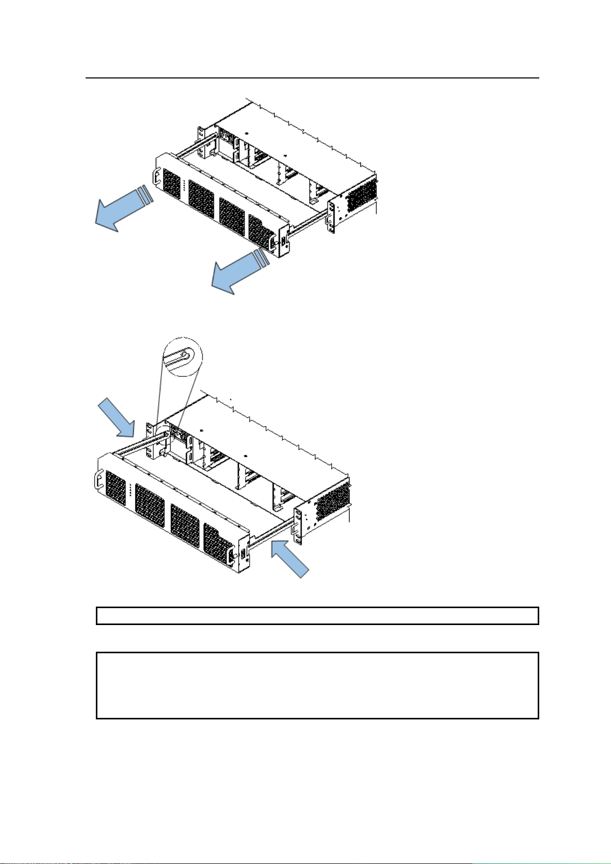
4-3. Detaching the Front Panel
NOTE
Handle the front panel carefully so as not to bend the rails.
IMPORTANT
After the front panel is installed, the ALARM LED on the front panel will light in the following
order.
DC1 → DC2 → FAN → TEMP
The ALARM LEDs not lighting in the above order indicates the front panel have not been
installed properly. Re-install the front panel.
1. Fully draw out the front panel.
2. The front panel can be detached by gently pushing both rails inward.
11
Page 12
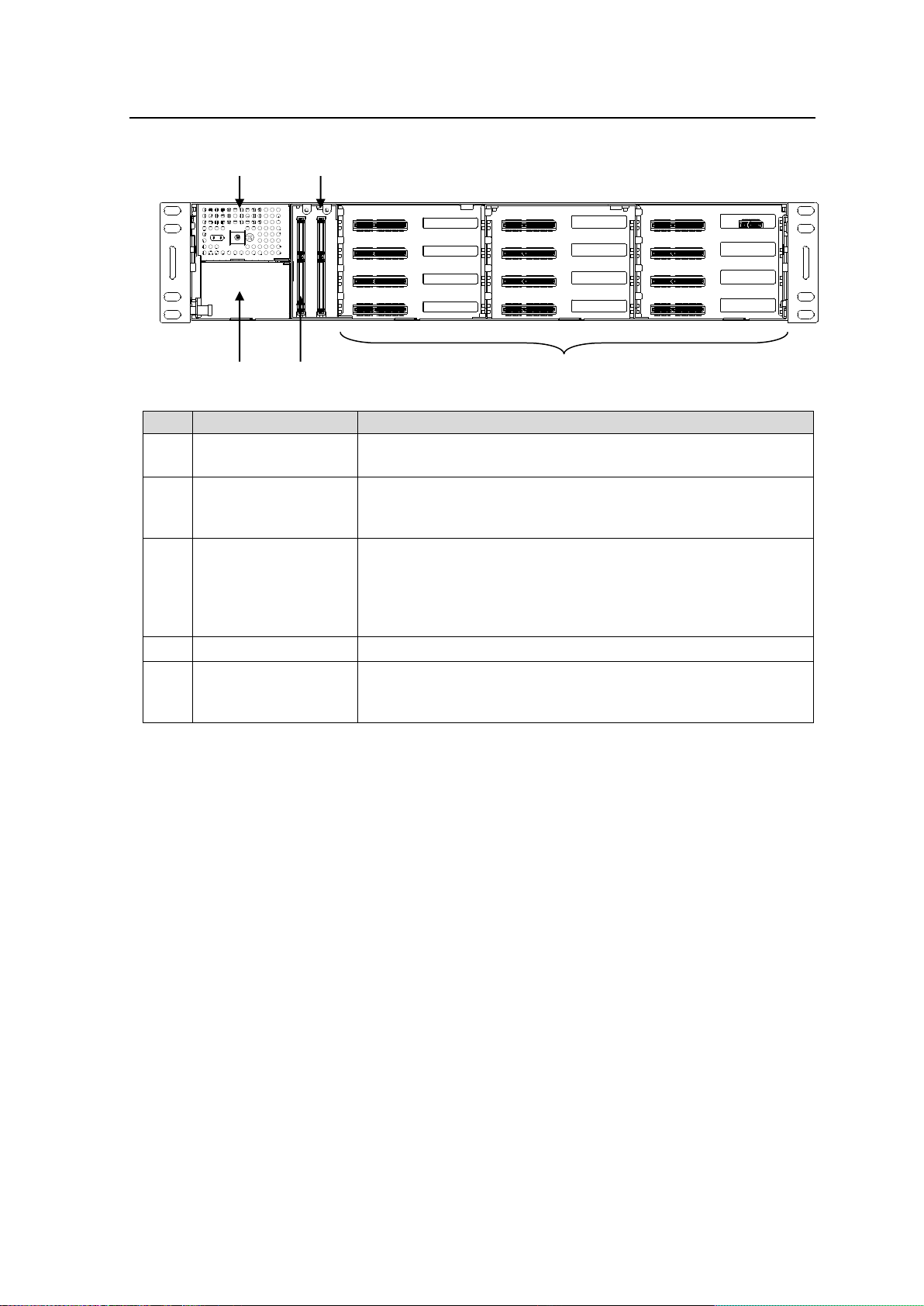
4-4. Front Interior
No.
Slot Type
Description
(1)
Power Supply 1 Slot
Dedicated power unit installed in this slot as standard.
Power is supplied when the power supply switch is turned on.
(2)
Power Supply 2 Slot
Slot for redundant power supply USF-212PS. Redundant
operation available when optional USF-212PS is installed.
A blank panel will otherwise cover the slot.
(3)
Control module Slot
Slot for network module.
SNMP Monitoring and GPI alarm output from the rear terminal
LAN1/LAN2/LAN A are available. Allows control over the
respective modules.
Allows to supply GENLOCK1/2 to respective slots.
(4)
Expansion slot
Not used.
(5)
USF Module Slots
Dedicated USF module slots. (Front USF modules)
For details on module operation, refer to the respective operation
manuals.
(1)
(2)
(3)
(4)
(5)
The slot configuration as shown below is revealed when the front panel is removed.
Redundant Power Supply System
Two power supply units can be mounted in the USF-212S. By mounting two power supply
units and turning both units on, operation can continue without the DC power supply shutting
down if either power unit fails.
The dedicated and optional USF-212PS power supply units are the same configuration, and
can be exchanged. Refer to Sec. 7. "Installing or Removing a Redundant Power Supply Unit”
for installation details.
12
Page 13
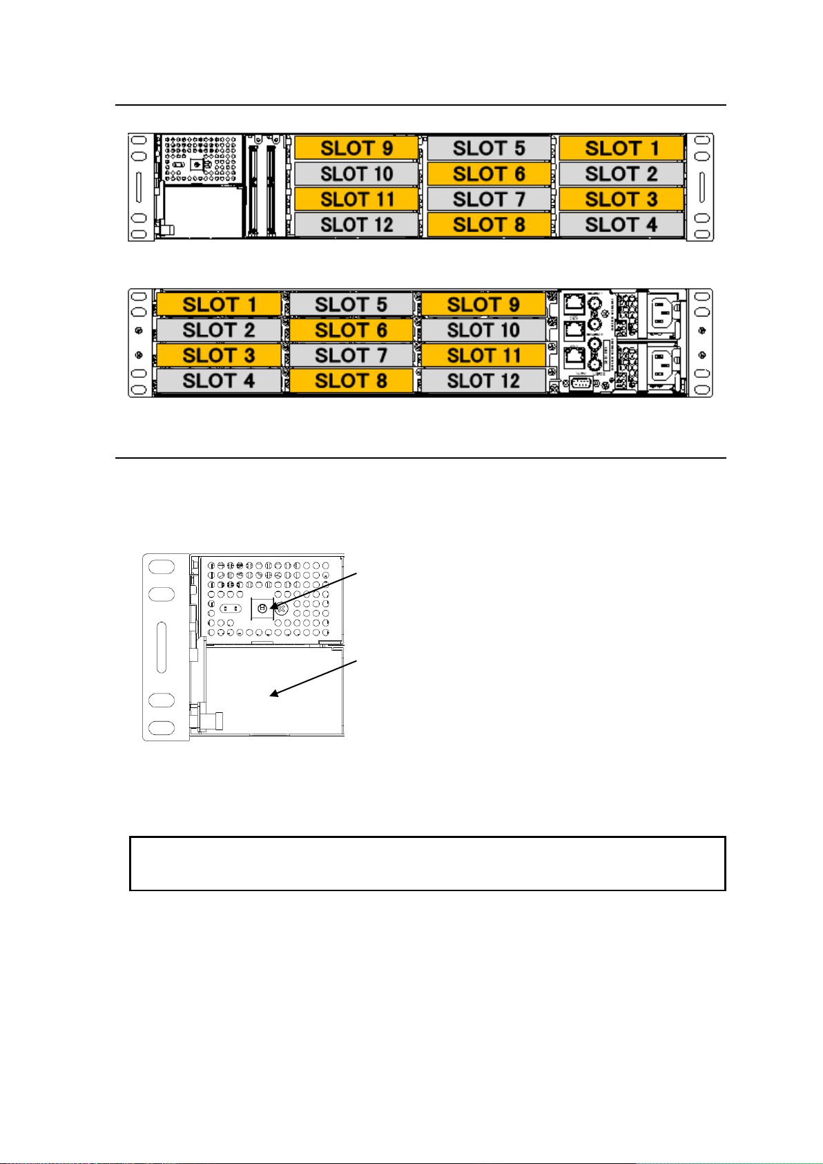
4-5. Slot Number
NOTE
Turn on the power supply switch on the front panel after connecting the power supply cable.
Turn on both the dedicated and redundant power supply units. If only one power supply unit is
turned on, redundant power will not be enabled if power fails in a power supply unit.
On/Off switch of Power
Supply Unit 1
Slot for USF-212PS optional
power supply unit
Front internal view.
Rear view.
4-6. Power Supply
Stand by power is activated in the USF-212S power supply unit when the AC cable is inserted.
When the front switch of the USF-212PS Power Supply unit is turned off, the DC supply to
USF-212S is disconnected. Redundant operation is available by installing an optional USF-212PS
power supply unit.
* When an optional USF-212PS is not installed, a blank panel is used to cover the blank power
supply unit 2 (PS2) slot.
13
Page 14
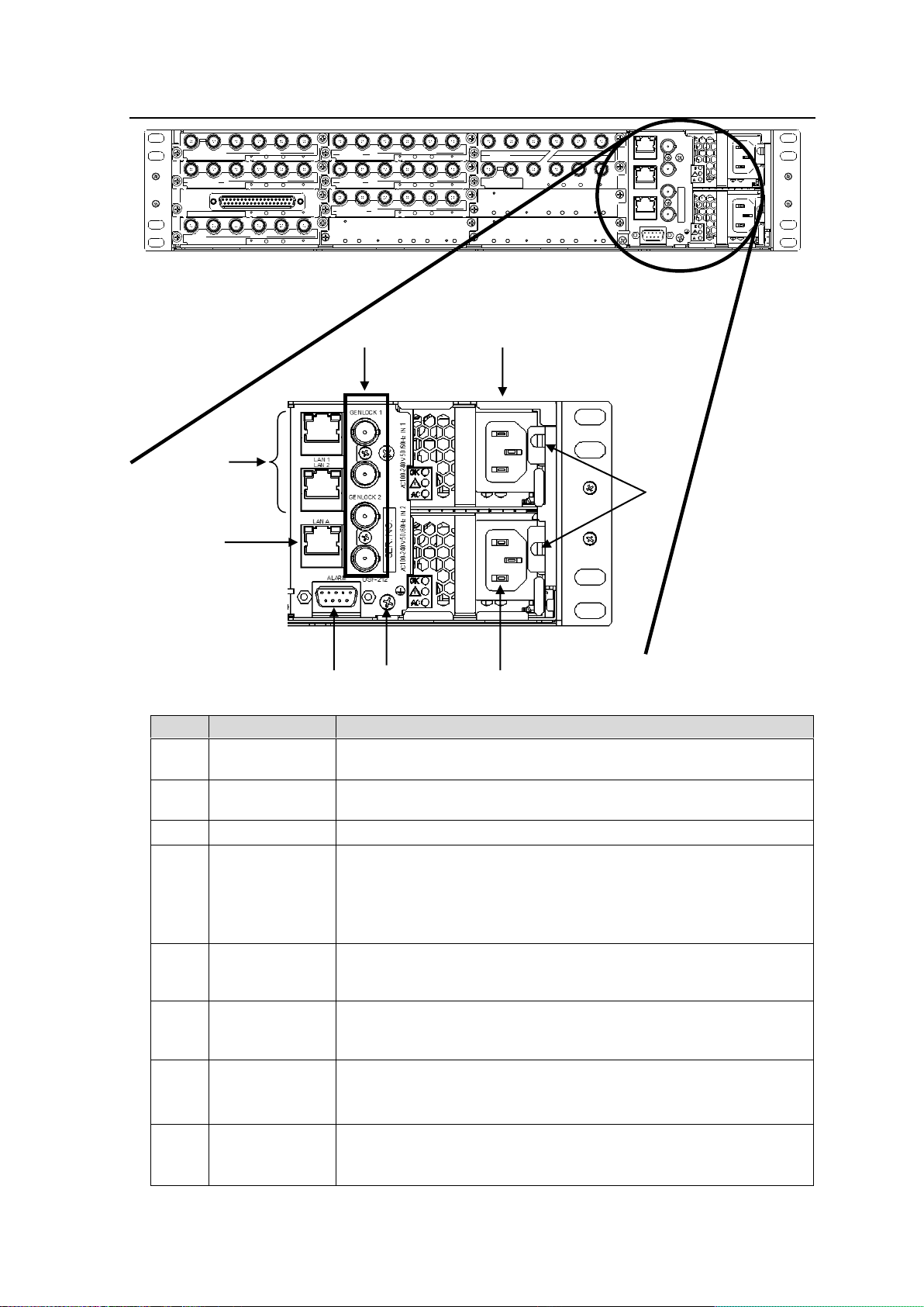
4-7. Rear Panel
VIDEO IN THRU
1 2
1
3G/HD/SDSDI IN
USF-1043FS
USF-1040VEA
1 2
2
3G/HD/SD SDI OUT
VIDEO OUT
334
4
IN OUT
1/2 3/4 5/6
7/8
-LTC
DIGITAL AUDIO IN
1/2 3/4 5/6
7/8
-LTC
DIGITAL AUDIO OUT
IN OUT
3G/HD/SD SDI
3G/HD/SD SDI
USF-1013MUX
USF-1013DEMUX
1 2
3G/HD/SD SDI IN
USF-1043DCC
1 2
3G/HD/SD SDI OUT
3 4
5 6 7
VIDEO OUT
1
VIDEO IN THRU
USF-1100VEA
8 9
2 3104
LAN 1
LAN 2
GENLOCK 1
GENLOCK 2
LAN A
SER. NO.
AC100-240V 50/60Hz IN 1
AC100-240V 50/60Hz IN 2
ALARM
USF-212
ANALOG AUDIO
SDI IN
1 2 3 4 5
SDI OUT
USF-108ADA
USF-1053DDA
No.
Connector
Descriptions
(1)
AC Inlet for
power supply 1
Supplies AC100 to 240V power using the provided power supply
cable.
(2)
AC Inlet for
power supply 2
When an optional USF-212PS is installed, supplies AC100 to 240V
power using the provided power supply cable.
(3)
Ground terminal
Grounds the power supply for safety.
(4)
GENLOCK 1
GENLOCK 2
Inputs genlock signals: Black Burst (BB) or tri-level sync.
The lower connector is for a loop-through connection. Terminate
with 75Ω. if unused.
*BB or tri-level sync signal input to GENLOCK1 or 2 should meet
respective modules signal format specifications.
(5)
LAN 1
LAN 2
USF-212S and each module installed in Slot 1 to 12 are accessible
via the USF-212S internal switching hub. Refer to Sec. 9-1-1.
"Connecting LAN 1 and LAN 2 Ports” for details.
(6)
LAN A
USF-212S and each module installed in Slot 1 to 12 are accessible
via the USF-212S internal router. Refer to Sec. 9-1-2 "LAN A Port”
for details.
(7)
ALARM
Open collector output allows the respective output of alarms.
Refer to Sec. 4-10. "ALARM Connector” for details.
Refer to Sec. 10-2. "Alarm Tab” for details on alarm terminal settings
(8)
AC Cord
Retainer
Installation
An anchor bolt is placed to install the AC cord retainer. Refer to
Sec. 2 "Installing AC Cord Retaining Clip” for installation.
(5)
(6)
(1)
(2)
(7)
(4)
(3)
(8)
14
Page 15
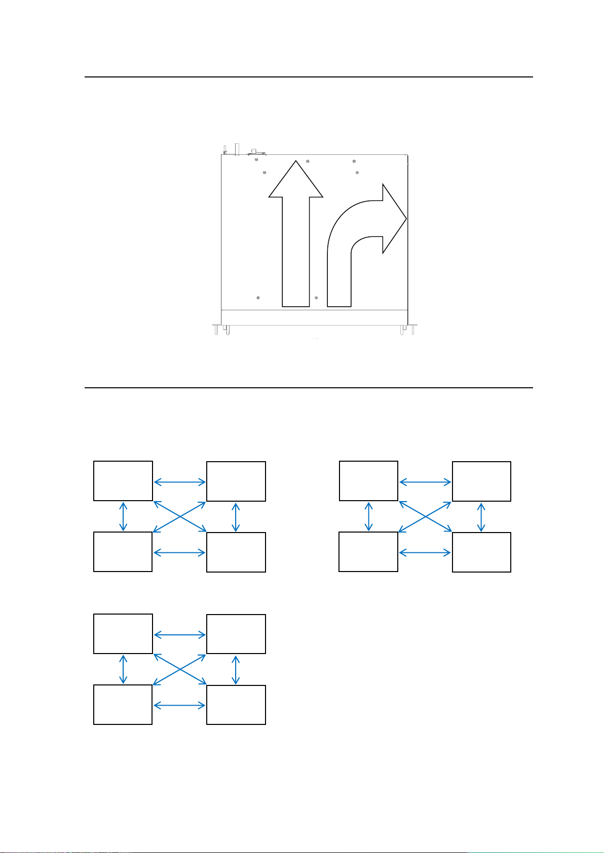
4-8. Fan
Slot 1
Slot 3
Slot 4
Slot 2
Slot 5
Slot 7
Slot 8
Slot 6
Slot 9
Slot 11
Slot 12
Slot 10
Fan unit prevents overheating from internal heat generation, pulling air through the front panel and
out the rear and right side panels. Do not block the fan vents.
(Rear Panel)
(Front Panel)
Air Flow Diagram
4-9. Internal SDI Bus
The USF-212S frame provides 4-slot groupings internal SDI bus which allows SDI signals to be
transferred bi-directionally. The signal application differs for each module. Refer to the operation
manual of each module for details.
♦Internal bus connections, Slots 1 to 4 ♦ Internal bus connections, Slots 5 to 8
♦Internal bus connections, Slots 9 to 12
15
Page 16
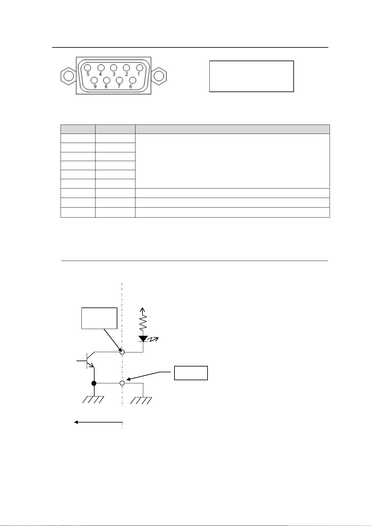
4-10. ALARM Connector
No.
Signal
Signal Details
1
ALARM 1
ALARM 1 to 6 functions assigned through Web GUI setting page.
Refer to Sec. 10-2. "Alarm Tab”
2
ALARM 2
3
ALARM 3
4
ALARM 4
5
ALARM 5
6
ALARM 6
7
GND
GND
8
GND
GND
9
GND
GND
Power
Supply
50mA
Max
Set the resistance so that the output
pin current stays within 50 mA.
R
External power supply
Max. +24VDC.
GND
ALARM 1
ALARM 2
USF-212S Side
Matching connector
9-pin D-sub male
*Using inch screws
9-pin D-sub female
ALARM Connector Assignment Table (9-pin D-sub female)
* Open collector alarm output (ALARM 1 to 6)
Maximum current limit: 24VDC / 50mA
4-10-1. Example of Alarm Connection
Example of ALARM1/ALARM2 (Open-Collector Output) Circuit
16
Page 17
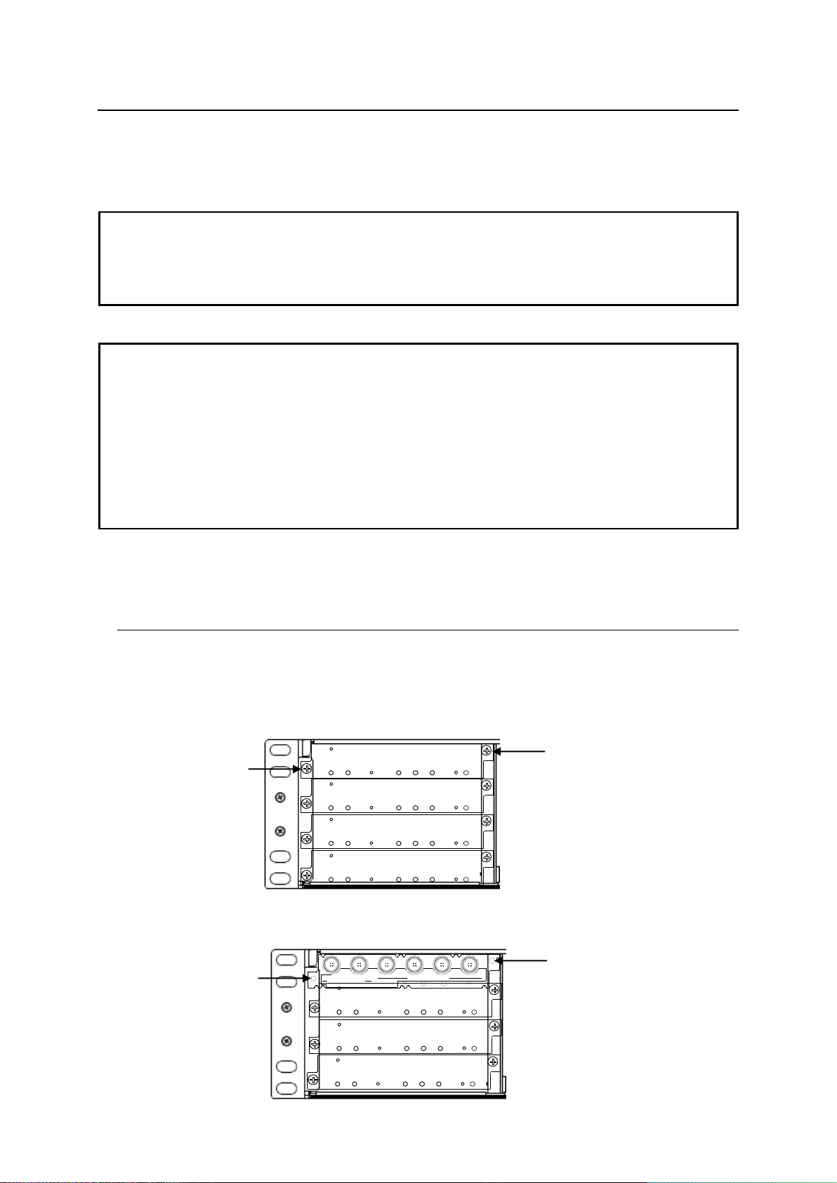
5. USF Module Installation
NOTE
USF Modules come as front and rear sets. Be sure to install set modules into the same (front and
rear) slot locations.
Always install the rear module first, then the front module.
Install blank panels over free slots to prevent foreign material from entering and overheating the
chassis.
IMPORTANT
Beware of the occurrence of electrical breakdown in USF Modules.
Wear an antistatic wrist strap or equivalent material to equalize the electrical potential of the
USF-212S unit and the worker’s body. Do not touch the PCB wiring or parts legs directly with your
fingers while working.
Each USF Module can be installed and uninstalled while the power is on in case of emergency.
Shut down the power for non-emergency work.
When installing/uninstalling the front module while the power is on, the front panel will be open
state. The fan will stop during the procedure, so it is essential to complete the installation within a
short period and to close the front panel immediately.
Be sure to shut down the power to install and uninstall a control module.
AC100
-
240V
50/60Hz
IN
S
E R
.
N O
.
Loosen
screw
Loosen
screw
3G/HD/SD SDI IN
USF-1043FS
1 2
1 2 3 4
3G/HD/SD SDI OUT
Fasten
screw
Fasten
screw.
USF Modules can be installed into any free slot. If multiple free slots exist, do not install modules
side-by-side but leave slots open to prevent overheating and facilitate signal connection from the rear
panel.
The procedure for installing the USF module in SLOT1 is described below as an example.
5-1. Installing of a USF Rear Module
1. Open the front panel and shut down the USF-212 power supply.
Refer to Sec. 4-2. "Opening the Front Panel”.
2. Slot 1 is the top slot in the left module block in the rear panel. Remove the blank panel by
detaching the two screws on both ends. Keep the blank panel and screws in a safe place after
removal.
3. Insert the rear module into the slot and fasten both screws.
17
Page 18
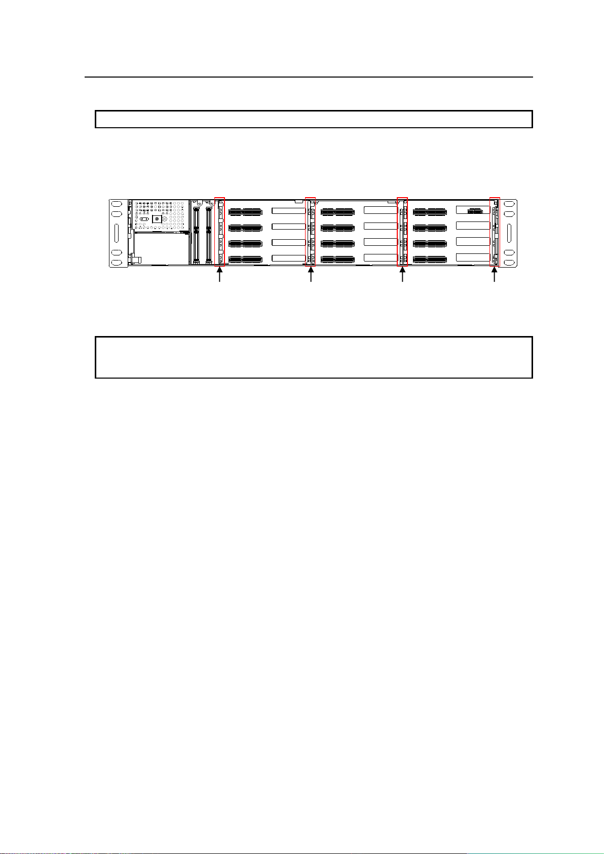
5-2. Installing a USF Front Module
IMPORTANT
Make sure to install the front module after installing the rear module.
IMPORTANT
Inserting the module by pressing on other than the handle may damage the module.
When a front module is installed with power on, maximum 1 minute is required until the
module is detected and identified on the web.
PCB Guide Rail
PCB Guide Rail
PCB Guide Rail
PCB Guide Rail
1. Slot 1 is the top slot in the right block of the front panel. Refer to Sec. 4-5. "Slot Number”
2. Set the front module on the guide rail and carefully insert the front module slowly.
PCB Guide Rail Locations
3. Push the handle until the front module clicks into the connectors.
18
Page 19
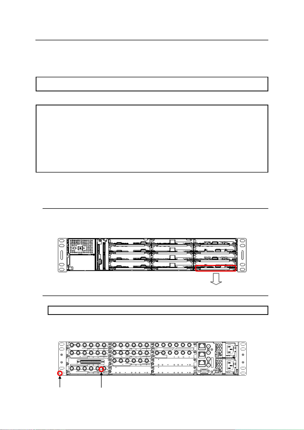
6. Replacing a USF Module
NOTE
When both front and rear module are to be replaced, make sure to replace the rear module after
pulling out the front module.
IMPORTANT
Beware of the occurrence of electrical breakdown in USF Modules.
Wear an antistatic wrist strap or equivalent material to equalize the electrical potential of the
USF-212S unit and the worker’s body. Do not touch the PCB wiring or parts legs directly with your
fingers while working.
Each USF Module can be installed and uninstalled while the power is on in case of emergency.
Shut down the power for non-emergency work.
When installing/uninstalling the front module while the power is on, the front panel will be open
state. The fan will stop during the procedure, so it is essential to complete the installation within a
short period and to close the front panel immediately.
Be sure to shut down the power to install and uninstall a control module.
IMPORTANT
Always remove the front module first, then the rear module without exception.
VIDEO IN THRU
1 2
1
3G/HD/SDSDI IN
USF-1043FS
USF-1040VEA
1 2
2
3G/HD/SD SDI OUT
VIDEO OUT
334
4
IN OUT
1/2 3/4 5/6
7/8
-LTC
DIGITAL AUDIO IN
1/2 3/4 5/6
7/8
-LTC
DIGITAL AUDIO OUT
IN OUT
3G/HD/SD SDI
3G/HD/SD SDI
USF-1013MUX
USF-1013DEMUX
1 2
3G/HD/SD SDI IN
USF-1043DCC
1 2
3G/HD/SD SDI OUT
3 4
5 6 7
VIDEO OUT
1
VIDEO IN THRU
USF-1100VEA
8 9
2 3104
LAN 1
LAN 2
GENLOCK 1
GENLOCK 2
LAN A
SER. NO.
AC100-240V 50/60Hz IN 1
AC100-240V 50/60Hz IN 2
ALARM
USF-212
ANALOG AUDIO
SDI IN
1 2 3 4 5
SDI OUT
USF-108ADA
USF-1053DDA
Screw
Screw
Follow the procedure described below to remove and replace a defective USF Module. Since no
electrical components are mounted on most USF rear modules, it is possible to recover proper operation
by replacing front modules.
The procedure for replacing a module in Slot 4 is described below as an example.
6-1. Removing the Front Module
1. Open the front panel and shut down the USF-212S power supply.
Refer to Sec. 4-2. "Opening the Front Panel.”
2. Slot 4 is the bottom slot in the right block of the front panel. Refer to Sec. 4-5. "Slot Number.”
3. Slide the module out using the grab handle.
6-2. Removing the Rear Module
1. Slot 4 is the bottom slot in the left block of the rear panel. Refer to Sec. 4-5. "Slot Number”
2. Loosen the screws on both ends. Secure the rear module while loosening the screws in order
not to drop the module.
19
Page 20
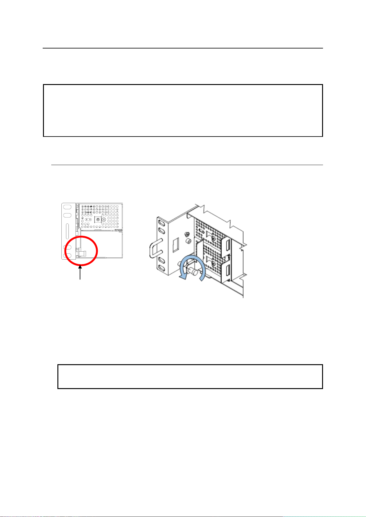
7. Installing or Removing a Power Supply Unit
IMPORTANT
To avoid electric shock, make sure to ground the grounding terminal before operation or pull out the
AC cable from the outlet.
A USF-212PS redundant power supply unit can be installed while the power is on, although the (main)
USF-212S power supply should normally be turned off when doing so. To install or remove a power
supply unit while the power is on, open the front panel. The cooling fan of the unit is turned off when
the front panel is open, so the installation should be completed in a short time to avoid overheating.
Close the front panel immediately after the operation is completed.
IMPORTANT
After connecting the power supply cable, turn the front switch on. Turn on both the dedicated
power supply and redundant power supply. If both power supplies are not turned on, redundant
operation will not work in the case of a power supply unit failure.
Screw of Fixing
Bracket
The procedure for installing a USF-212PS Optional Redundant Power Supply Unit into a USF frame is
described as follows. Power supply unit replacement can be performed in the same manner.
7-1. Installing a Power Supply Unit
The procedure for installing a USF-212PS unit into the PS2 Slot is explained as an example.
1. Open the front panel. Refer to Sec. 4-2.”Opening the Front Panel”
2. Turn counterclockwise to remove the screw of the power supply mounting bracket.
3. Remove the blank panel when a power unit blank panel is installed.
4. Insert the power supply unit USF-212PS slowly into the power supply slot from the front.
5 Fix the power supply unit with the fixing bracket removed in step 2, then tighten the screw.
6. Connect the power supply cable from the rear.
7. Turn on the USF-212PS front switch.
8. Close the front panel.
20
Page 21
7-2. Removing a Power Supply Unit
The procedure for removing a USF-212PS from the PS1 SLOT is explained as an example.
1. Open the front panel. Refer to Sec. 4-2 "Opening the Front Panel.”
2. Shut down the Power Supply 1.
3. Unplug the AC cable of Power Supply 1 from the back side. Refer to Sec. 2 "Installing the AC
Cord Retaining Clip” for details.
4. Loosen the screw of the power supply fixing bracket by turning it counterclockwise. When the
screw is completely loose, the fixing bracket can be detached.
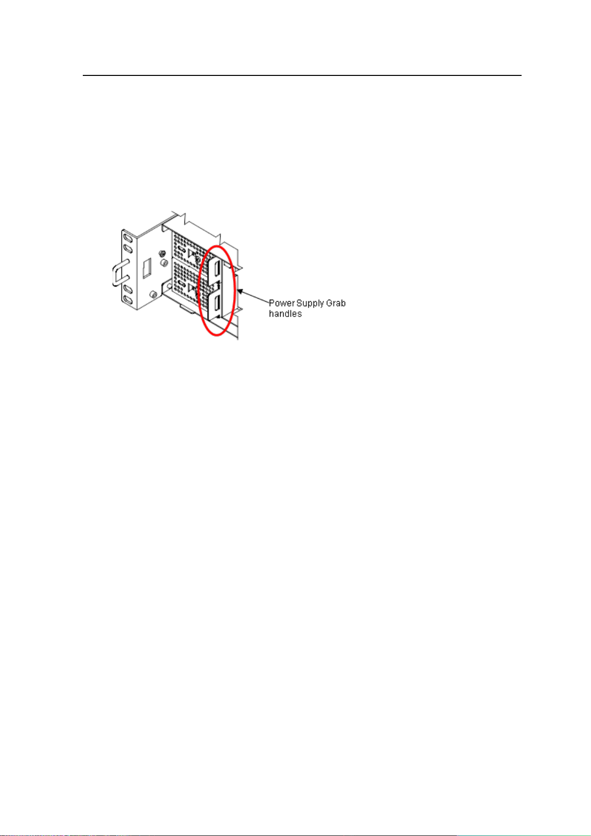
5. Pull the unit out slowly using the grab handle.
6. Fix the remaining power supply unit with the fixing bracket removed in Step 4, then tighten the
screw.
7 Close the front panel immediately.
21
Page 22
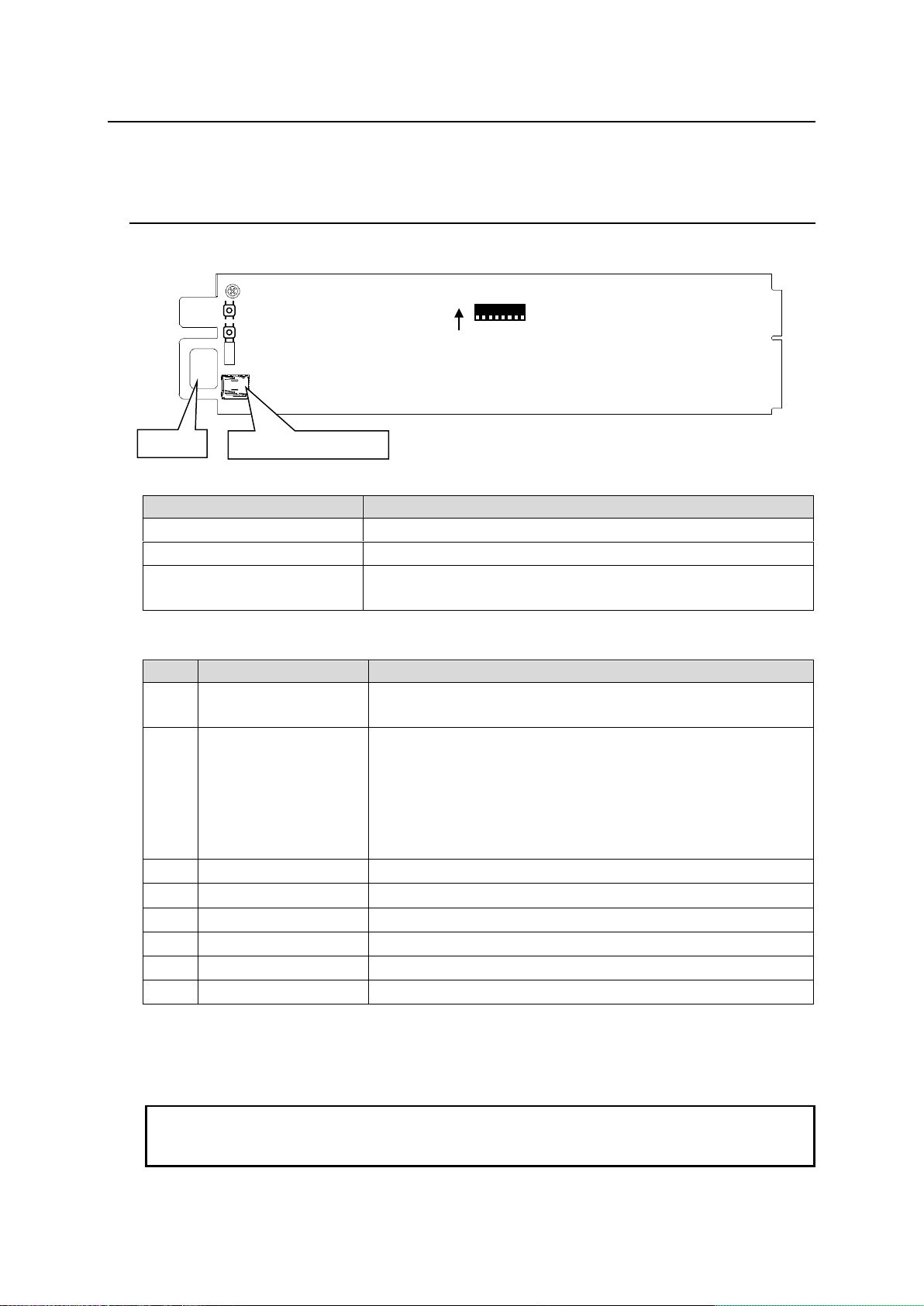
8. Control Module
Name
Descriptions
Switch S2
CPU reset switch. Not used normally.
Switch S3
Reset switch for the built-in hub. Not used normally.
Micro SD CARD Connector
For maintenance purposes only.
Do not connect Micro SD CARD.
No.
Factory Setting
Description
1
Off
Off: Front Panel Open warning alarm is enabled.
On: Front Panel Open warning alarm is disabled.
2
Off
Off: Normal use.
On: The USF-212S operates at the default network settings.
If the IP address of the LAN1/2 or LAN A port is forgotten, use
this setting, which allows you to access the USF-212S from the
web browser with the factory default IP address of the port.
(LAN1/2: 192.168.0.10, LAN A: 172.16.0.10) The lost network
configuration is displayed on network tab of the web page. (*1)
3
Off
Off: Do not change the setting.
4
Off
Off: Do not change the setting.
5
Off
Off: Do not change the setting.
6
Off
Off: Do not change the setting.
7
Off
Off: Do not change the setting.
8
Off
Off: Do not change the setting.
IMPORTANT
If SW2 is turned ON while the network cable is connected, IP addresses are set as default
(LAN1/2: 192.168.0.10 to 22, LAN A: 172.160.0.10). Proceed after confirming these IP
addresses do not conflict with the IP addresses of other devices in the network.
S2
S3
DS1
8
ON
1
Handle
Micro SD connector
Make sure to shut down the power when replacing the control module.
8-1. Internal Control Module Settings
Remove the module by loosening the screw on front and pulling the module out using the grab
handle.
DS1 Settings
*1 When DS1-2 is turned on, IP addresses of Slot 1 to 12 also returns to default
(192.168.0.11 to 22).
22
Page 23
9. Control via Web GUI
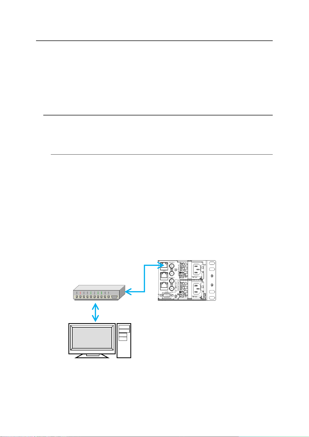
LAN1 LED (LAN2 LED)
Lit Green: Connected
Flashing Orange: Transmitting
and receiving data
USF-212S Rear
Web Browser
SNMP Manager
USF-212S operation can be monitored by a web browser or SNMP Manager via a PC-network
connection. Power supply, fan, and temperature states can be displayed by opening the USF-212S
Web GUI from a web browser. Control and monitoring of the modules (*1) installed in USF-212S can be
done via Web GUI. ALARM function assignments of the rear ALARM connector can be set via Web GUI.
It is also possible to monitor power supply, fan, temperature, modules (1*) through an SNMP manager.
(*1)Possible for the network support modules only. Refer to the operation manual of respective
modules.
9-1. Connecting USF-212S to a PC
Connect LAN 1, LAN 2 or LAN A connector to a PC via a hub.
LAN 1, LAN 2 and LAN A have different functions.
9-1-1. Connecting LAN 1 and LAN 2 Ports
The installed control modules are connected to the USF-212S internal switching hub. The LAN
1 and LAN 2 ports on the rear panel are also connected to the USF-212S internal switching
hub. This requires different IP addresses to be set for these ports and other devices in this
network. When a large amount of data is to be exchanged per module, use the LAN 1 or LAN
2 port.
Factory settings
LAN 1 and LAN 2 IP address: 192.168.0.10
Refer to LAN 1 and LAN 2 settings of Sec. 10-3. "Network Tab” for details on changing network
settings.
Connection Example
23
Page 24
9-1-2. LAN A Port
OS
Windows® 7, 8, 8.1 operating system
Professional (32/64bit)
CPU
Intel® Core™ 2 Duo processor, 2GHz or more
Memory
2GB or more
Display
Resolution of 1280×1024pixels or higher recommended
Must be capable of full color (24-bit) display
Network port
Ethernet at least one port
100BASE-TX/1000BASE-T
Network cable
100BASE-TX: Category 5 or better
1000BASE-T: Category 6 or enhanced category 5
Web Browser
Windows® 7 Internet Explorer11
Windows® 8 Internet Explorer11
Google Chrome 45.0.2454 or later
Fire fox 40.0.3 or later
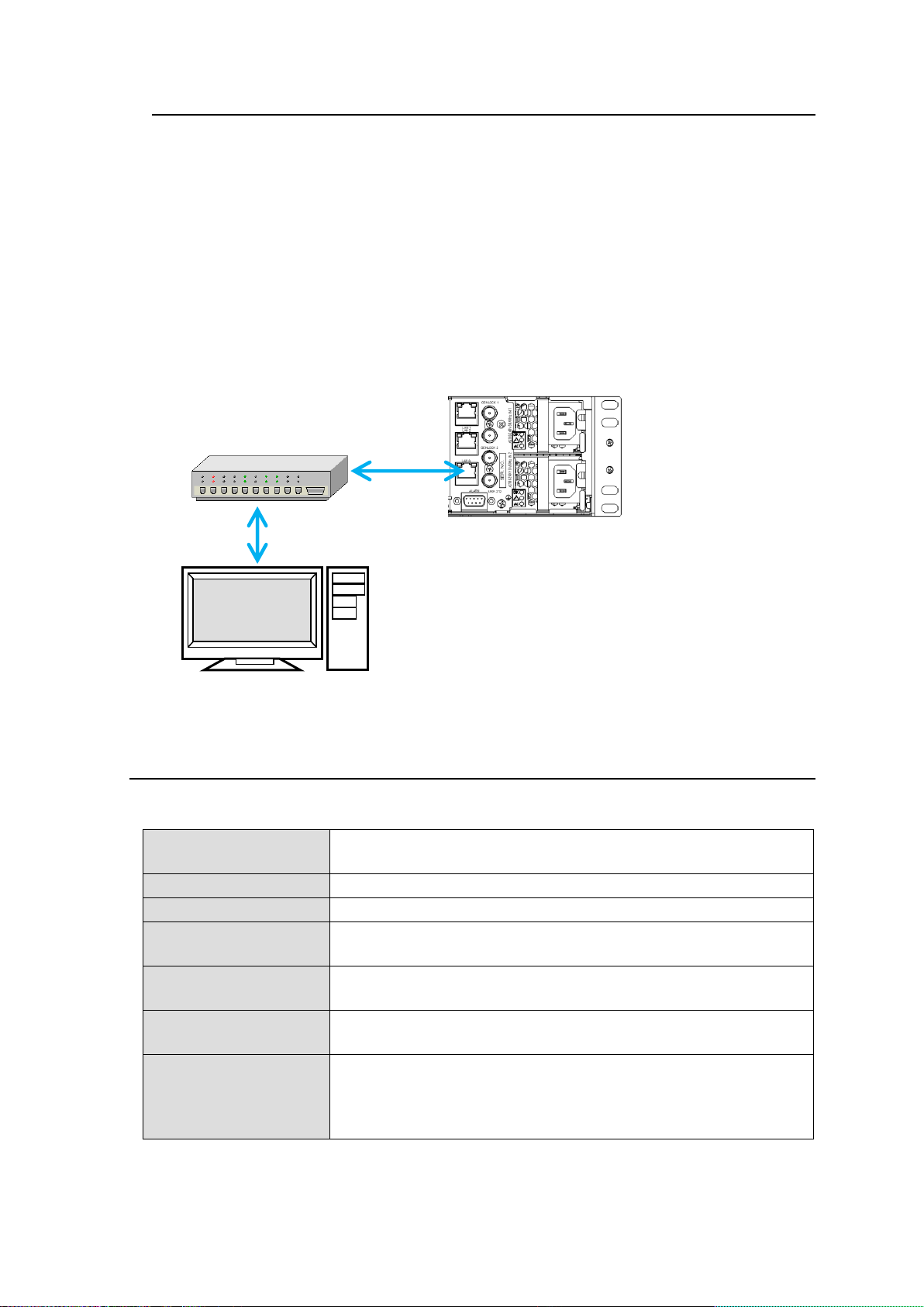
LAN A LED
Lit Green: Connected
Flashing Orange: Transmitting
and receiving data
USF-212S Rear Panel
Web Browser
SNMP Manger
LAN A port functions via the built-in USF-212S router. Therefore, LAN A can display
respective modules states via Web GUI and SNMP monitor with one IP address assigned for
respective modules IP addresses. When building a large scale system with multiple
USF-212S units, you can reduce the number of IP addresses. Connect the LAN A Port via an
external switching hub.
Factory settings
LAN A IP Address: 172.16.0.10
Refer to WAN Settings of Sec.10-3. “Network Tab” for details on changing network settings.
Connection Example
9-2. PC System Requirements
Web GUI requires the following minimum PC specifications.
24
Page 25
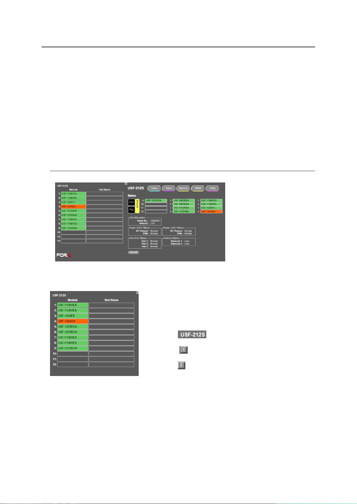
10. USF-212S Web GUI
The modules mounted in slots 1 to 12 and associated slot names
are indicated.
Modules whose connection is lost are indicated in gray. Clicking
on a mounted module (slot 1 to 12) displays its setting window in
the right side of the Web GUI.
Clicking on changes the window to USF-212S Status
Tab.
Clicking on makes the module list window (slots 1 to 12)
disappear and a full screen window appear.
Clicking on
makes the module list (slots 1 to 12) reappear.
Refer to the respective module operation manual for details on
module window settings on Web GUI.
Module status web browser display settings are different between LAN1, 2 and LAN A.
Displaying the web browser from LAN 1 and LAN 2
Open the web browser on the PC connected to LAN 1 and LAN 2, then input the address
http://192.168.0.10/ (factory default setting). The status of USF-212S is displayed on the web
browser.
Displaying the web browser from LAN A
Open the web browser on the PC connected to LAN A, then input the address
http://172.16.0.10/ (factory default setting). The status window of USF-212S is displayed on
the web browser.
10-1. Status Tab
Clicking the Status tab opens a window as shown below.
Clicking Refresh allows you to update the window contents.
25
Page 26
Status
Serial No.
Serial number
Version
Version information
DC Output
DC output status of the Power Unit is indicated.
Normal: Functioning
Abnormal: Not functioning. Immediately turn off the power supply and
contact your supplier.
Fan
Operation status of Power Unit FAN is indicated.
Normal: Functioning
Stopped: The fan has stopped. Immediately turn off the power supply
and contact your supplier.
Fan 1 to 3
Status of front FAN 1 to FAN 3. Refer to Sec. 4-1 "Front Panel” for
FAN location.
Normal: Functioning
Stopped: The fan has Stopped. Immediately turn off the power supply
and contact your supplier.
Genlock 1
Detected: Input signal is detected.
Loss: Input signal is not detected.
Genlock 2
Detected: Genlock 2 input signal is detected.
Loss: Input signal is not detected.
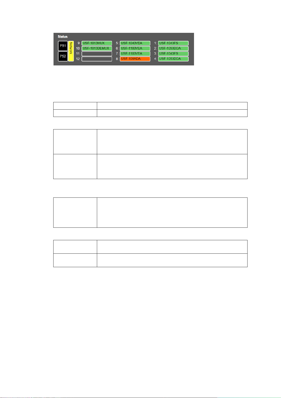
Model names of the modules installed in slots 1 to 12 of USF-212S are displayed.
PS1 and PS2 indicate the respective power supply mounting and operational states.
A red flashing LED indicates abnormal power output, inoperative fan, or a high temperature
state being detected.
Unit Information
Power Unit 1 Status / Power Unit 2 Status (*)
* Not indicated when the power is turned on for a power supply that is not installed.
Front Fan Status
Genlock Status
26
Page 27
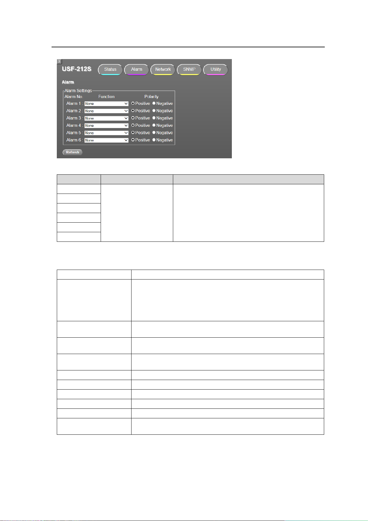
10-2. Alarm Tab
Item
Function(Default)
Description
Alarm 1
None
Assigns a function for each alarm terminal.
A function is selected from the list below.
Polarity enables you to select alarm output polarity.
Polarity is positive by default.
Alarm 2
Alarm 3
Alarm 4
Alarm 5
Alarm 6
None
No function is set.
Unit All Alarm
Alarm signal output if one of failures listed below occurs:
Abnormal DC output from power supply unit 1 or 2.
Stopped FAN 1, 2, or 3
High temperature
Front panel open
Power Unit1/2 Alarm
Alarm signal output: Indicates abnormal DC output from Power
Supply unit 1 or 2.
Power Unit1 Alarm
Alarm signal output: Indicates abnormal DC output from Power
Supply unit 1.
Power Unit2 Alarm
Alarm signal output: Indicates abnormal DC output from Power
Supply unit 2.
FAN 1 / 2 / 3 Alarm
Alarm signal output: Indicates stopped FAN 1, 2 or 3.
FAN 1 Alarm
Alarm signal output: Indicates stopped FAN 1.
FAN 2 Alarm
Alarm signal output: Indicates stopped FAN 2.
FAN 3 Alarm
Alarm signal output: Indicates stopped FAN 3.
Temperature Alarm
Alarm signal output: High Temperature indication.
Front Panel Open Alarm
Alarm signal output: Indicates front panel open longer than 5
minutes.
Clicking an Alarm tab opens a window on the web browser as shown below.
Clicking Refresh allows you to update the window contents.
* Refer to Sec. 4-10. "Alarm Connector” for terminal number details on Alarm 1 to 6.
Function
27
Page 28
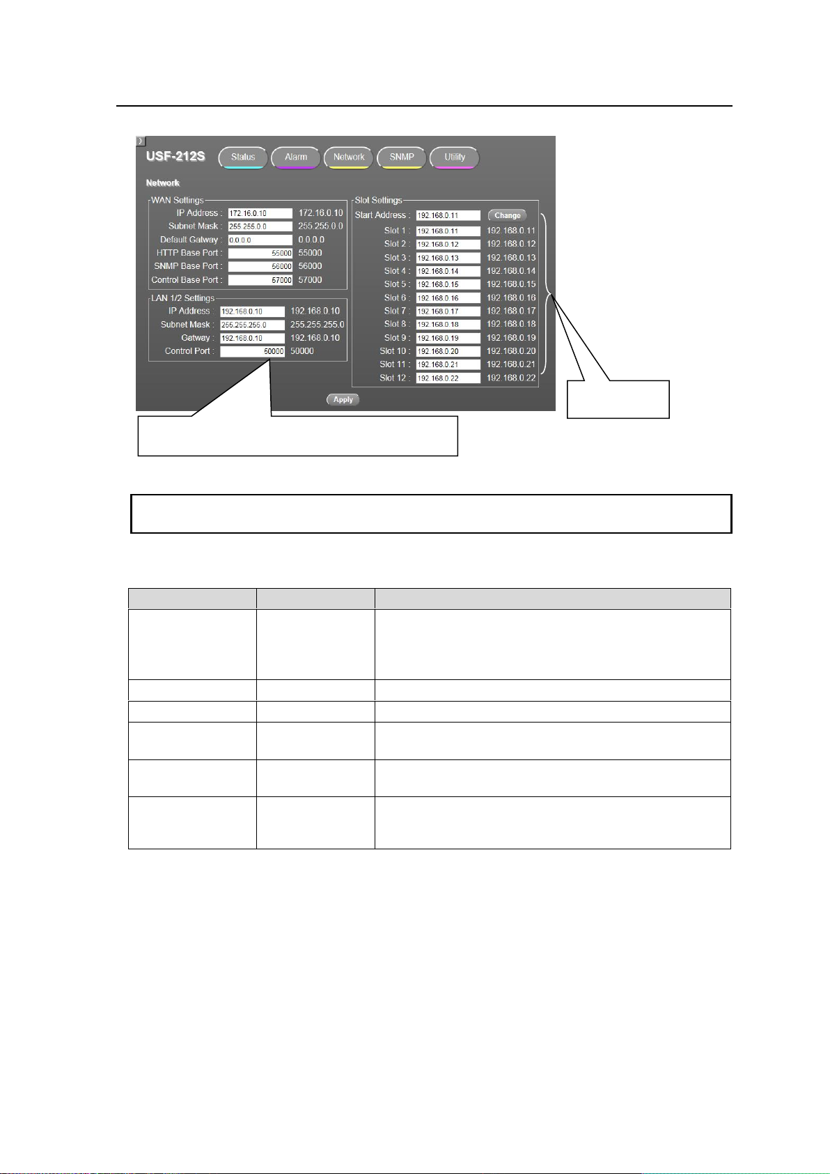
10-3. Network Tab
IMPORTANT
Setting changes performed in the Network Tab require the USF-212S to be restarted after they
are entered by clicking Apply.
Item
Factory Setting
Description
IP Address
172.16.0.10
Sets the external LAN A IP Address.
(Setting Range: 10.0.0.0-10.255.255.255,
172.16.0.0-172.31.255.255,
192.168.0.0-192.168.255.255)
Subnet Mask
255.255.0.0
Sets the external LAN A Subnet Mask.
Default Gateway
0.0.0.0
Sets the external LAN A Default Gateway.
HTTP Base Port
55000
Sets the TCP/UDP port number through which the Web
GUI accesses to the external LAN A.
SNMP Base Port
56000
Sets the TCP/UDP port number through which the
SNMP Manager accesses to the external LAN A.
Control Base Port
57000
Sets the TCP/UDP port number through which
FA-10DCCRU Remote Control Unit accesses to the
external LAN A.
Input values to change settings. The changes are
applied by clicking Apply.
Set values are
indicated.
Clicking the Network tab opens a window as shown below.
WAN (LAN A) Settings
Network settings of WAN side (LAN A) port are set.
Example 1: To Display Slot 1 Module on the Web Browser by Addressing.
When the HTTP Base Port setting is 55000, input http://172.16.0.10:55001 in the address bar of the
web browser to display the Slot 1 module Web GUI.
Similarly, input http://172.16.0.10:55002 for Slot 2.
Example 2: To Get/Set Slot 1 Module via SNMP Manager
When SNMP Base Port setting is 56000, input 172.16.0.10 for the IP address. Input 56001 for the
SNMP port number.
Similarly, input 56002 for the port number of Slot 2.
28
Page 29
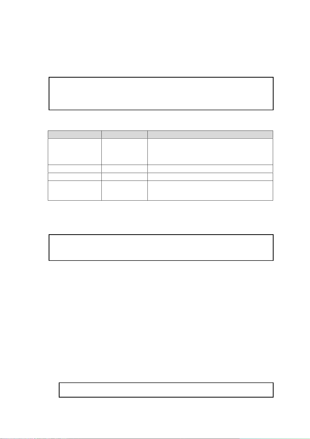
Example 3: To Control Slot 1 Module by Remote Control Connection.
IMPORTANT
Multiple port numbers, HTTP Base Port/ SNMP Base Port/ Control Base Port, are used in order
to prevent system glitches from occurring when a PC connects to and control multiple modules
on the USF-212S via the external LAN A port.
The port numbers of USF-212S and other components should all be set to different settings in
the control PC.
Item
Factory Setting
Description
IP Address
192.168.0.10
Sets IP Address of the LAN 1/2 port.
(Setting Range: 10.0.0.0-10.255.255.255,
172.16.0.0-172.31.255.255,
192.168.0.0-192.168.255.255)
Subnet Mask
255.255.255.0
Sets Subnet Mask of the LAN 1/2 port.
Gateway
192.168.0.10
Sets Gateway of the LAN 1/2 port.
Control Port
57000
Sets the TCP/UDP port number through which
FA-10DCCRU Remote Control Unit accesses to the
LAN 1/2 port.
IMPORTANT
LAN 1/2 and modules in Slot 1 to 12 are connected to the built-in USF-212S switching hub.
Accordingly, avoid using the same IP addresses of LAN 1/2 port and Slot 1 to 12 as those of
devices in the network. If the addresses are improperly set, network failure may occur and
produce instable operation or web displays may not appear.
NOTE
Set the forth octet of the start address, Slot 1, with the range 1 to 243. Any value of 244 and
over will not be set since it exceeds the settable range.
When the Control Base Port setting is 57000, input 172.16.0.10 for the IP address. Input 57001 for
the port number.
Similarly, input 57002 for the port number of Slot 2.
Refer to the FA-10DCCRU operation manual for further details on setting.
LAN 1/2 Settings
LAN 1 or LAN 2 port that connects to the built-in USF-212S switching hub can be set.
Subnet Mask and Gateway setting values apply to all modules mounted in slots 1 to 12.
IP Address and Gateway should be the same address when utilizing the router function to
control the Web display and SNMP together through LAN A.
Slot settings
Two procedures allow each slot IP address to be set one by one, or in one operation.
Setting one by one
Input IP addresses in Slots 1 through 12. The addresses are set when Apply is clicked.
Setting in one operation
1. Input an IP address (for instance 192.168.0.11) that you want to set to Slot 1 in Start
Address.
2. Click Change.
3. An IP address plus 1 (192.168.0.12) will appear automatically in the input column of
Slot 2.
4. Similarly, the IP addresses plus 2 to 11 respectively to the Slot 1 IP address will
appear in the input columns of Slot 3 to 12.
5. Click Apply to apply these changes.
29
Page 30
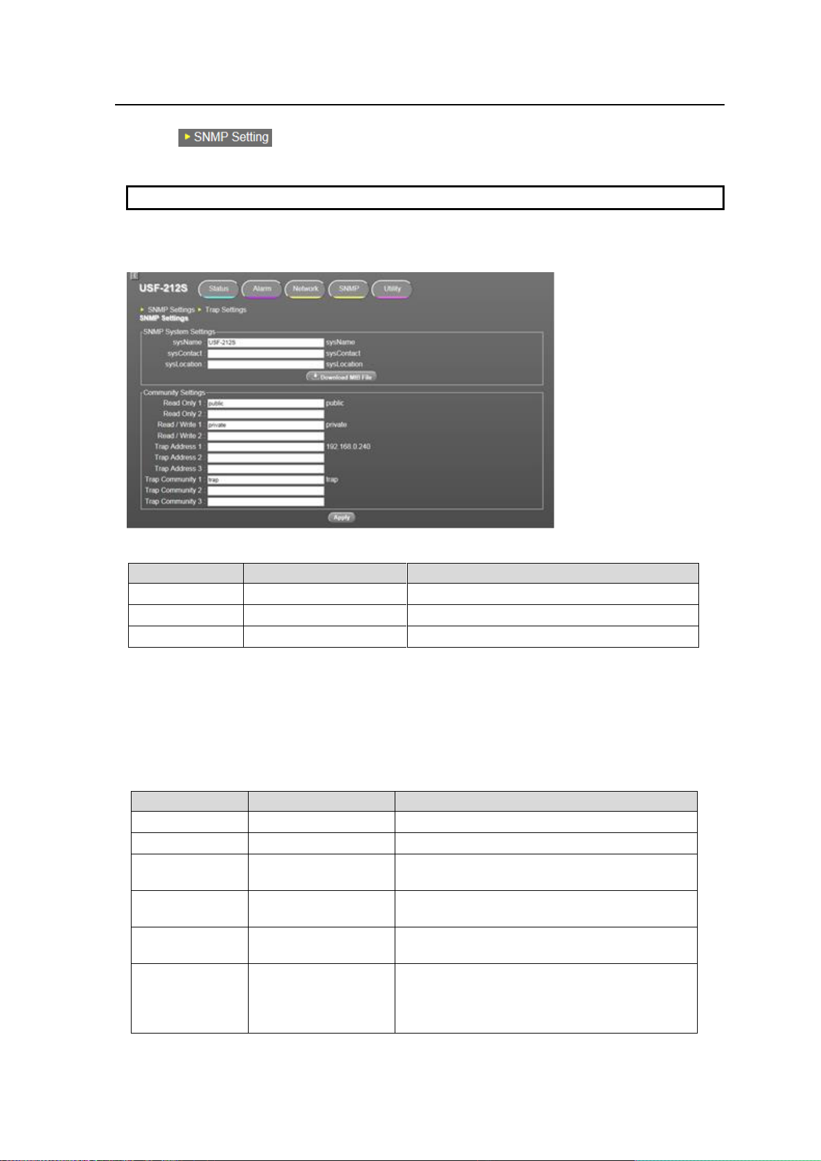
10-4. SNMP Tab
IMPORTANT
In order to confirm changes in SNMP Tab, click Apply to restart the USF-212S.
Item
Number of Characters
Description
sysName
Under 31 Characters
Name of unit
sysContact
Under 31 Characters
Administrator comments
sysLocation
Under 31 Characters
Details on installation location
Item
Number of Characters
Description
Read Only1-2
Under 31 Characters
Read only community name of SNMP.
Read/Write1-2
Under 31 Characters
Read and write community name of SNMP.
Trap Address 1-3
---
IP address of SNMP manager to which SNMP
trap is sent.
Trap Community
1-3
Under 31 Characters
Community name to send trap to Trap 1
Address.
Trap1 Address
---
IP address of SNMP manager to which SNMP
trap is sent.
Apply
-
Applies setting change of SNMP System or
Community Settings.
The applied settings appear in the right columns
when they are applied.
Clicking SNMP Tab opens the following page on the web browser.
Clicking also opens the same page.
SNMP Settings
This page allows you to apply various settings to monitor USF-212S by SNMP manager.
SNMP System Settings
Downloading of MIB (Management Information Base) file.
The MIB file can be downloaded according to the following procedure.
1. Click Download MIB File.
2. Click Save of FORA-USF-212S-MIB.zip file.
3. Unzip the file and load it to SNMP Manager.
Community Settings
30
Page 31
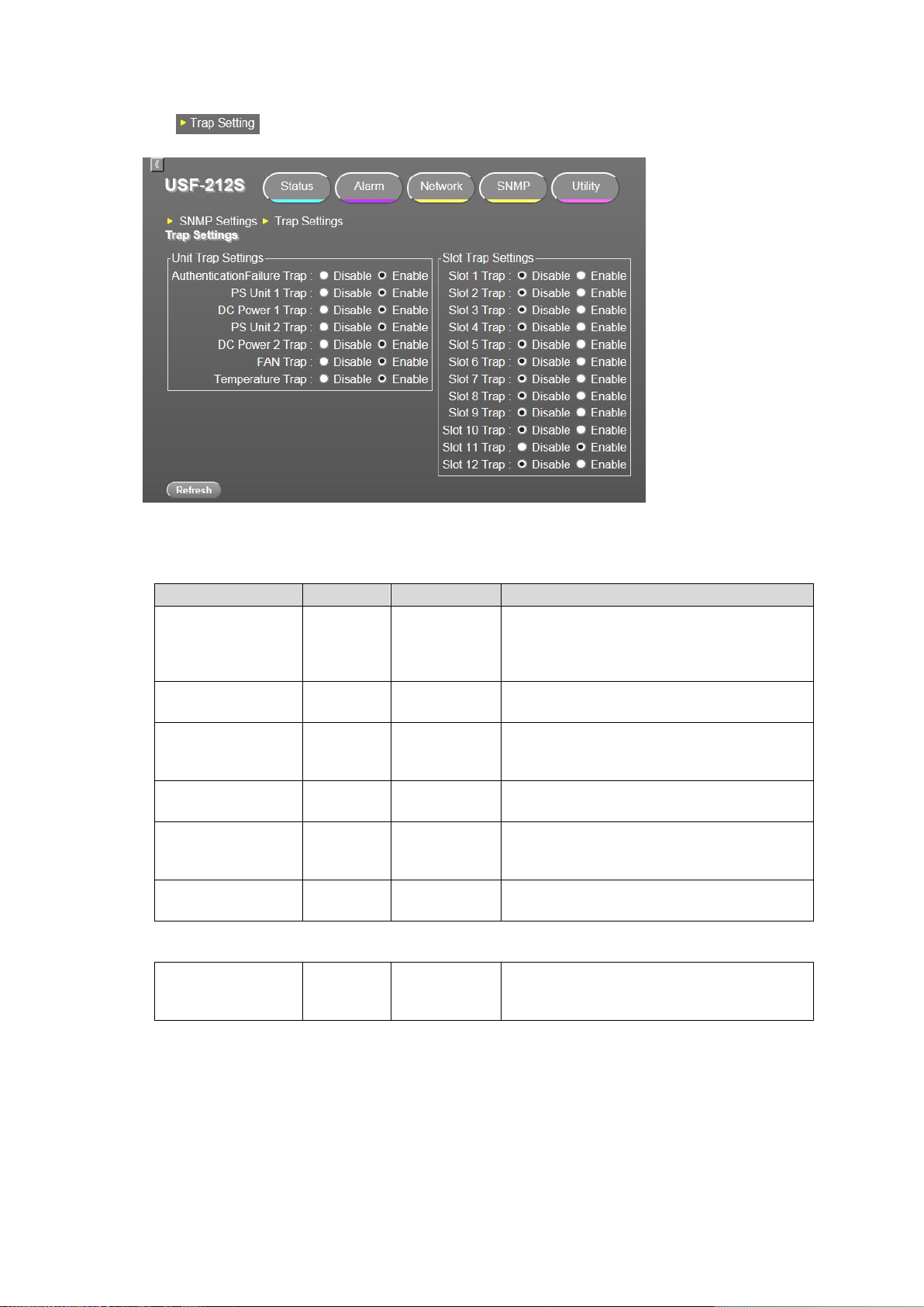
Trap Settings
Item
Default
Settings
Description
Authentication
failure Trap
Enable
Disable
Enable
Enable: If the community names set on
Read Only1, 2/ Read/Write1, 2 are different
from the community names set by SNMP
manager, a Trap command is sent.
PS Unit 1 Trap
Enable
Disable
Enable
Enable: If Power Supply Unit 1 failure
occurs, a Trap command is sent.
DC Power 1 Trap
Enable
Disable
Enable
Enable: If DC power supply failure occurs
in Power Supply Unit 1, a Trap command is
sent.
PS Unit 2 Trap
Enable
Disable
Enable
Enable: If Power Supply Unit 2 failure
occurs, a Trap command is sent.
DC Power 2 Trap
Enable
Disable
Enable
Enable: If DC power supply failure occurs
in Power Supply Unit 2, a Trap command is
sent.
FAN Trap
Enable
Disable
Enable
Enable: When conditions of fan 1 to 3 are
changed, a Trap is sent.
Slot1 to 12 Trap
Enable
Disable
Enable
Enable: If communications between Slot1
to Slot12 with the control board are lost, a
Trap command is sent.
Click .
This window allows you to set various trap transmission from USF-212S to SNMP Manager.
Clicking Refresh updates window to the latest.
Unit Trap Settings
Slot Trap Settings
31
Page 32
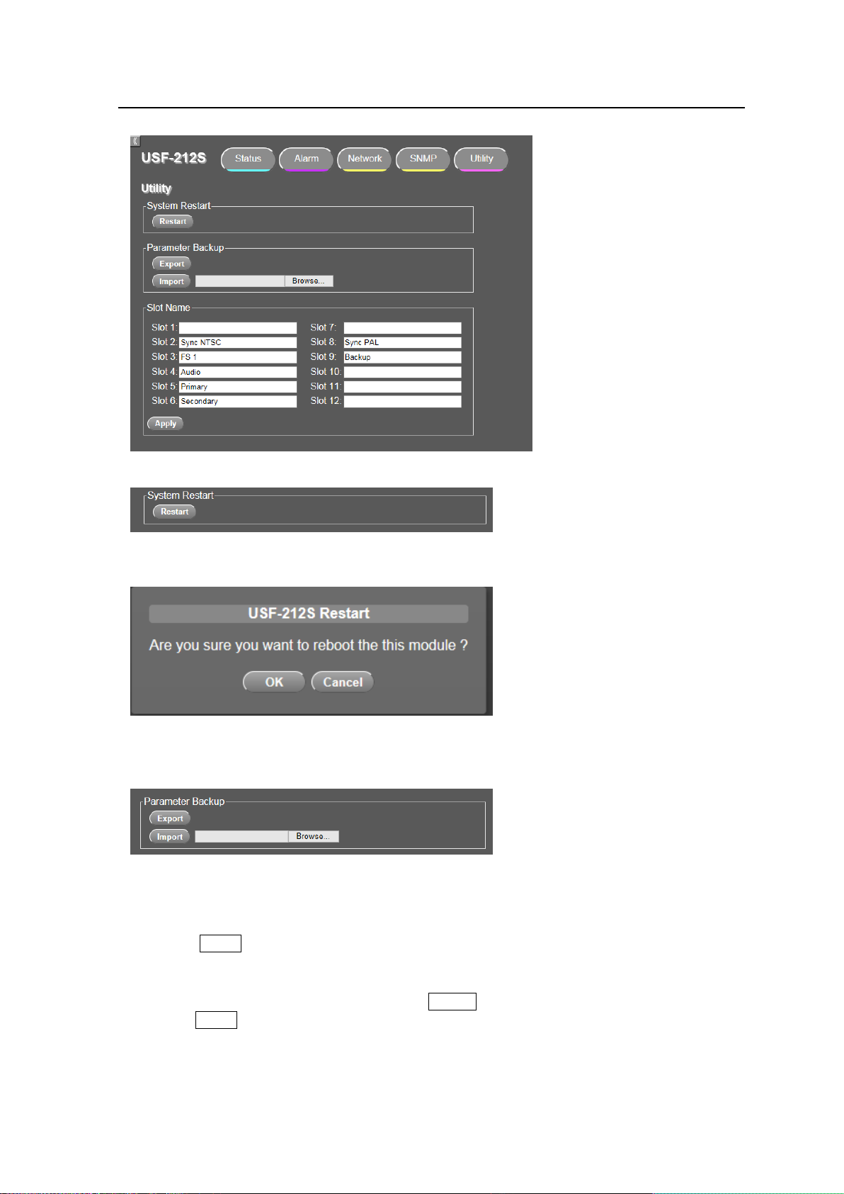
10-5. Utility Tab
Clicking the Utility tab opens the window as shown below on the web browser.
System Restart
Execute System Restart when network settings or SNMP settings are changed.
The following confirmation window will appear when Restart is clicked.
* Other tab windows cannot be accessed until this window is closed
Click OK to execute restart.
Parameter Backup
Exports (saves as a file) and imports (loads from a file) USF-212S setting parameters.
Export
(1) Click Export to save the settings to a file. (File name: usf-212s.csv (Default))
Import
(1) Select a setting parameters file by clicking Browse.
(2) Click Import to load the settings.
When the following parameters are changed, USF-212S is updated after the unit is restarted.
IP address / Subnet mask / Default gateway / Communication port / IP addresses of modules /
/SNMP (Excluding Trap Enable / Disable settings)
32
Page 33
IMPORTANT
Save setting parameters to a UTF-8 encoded CSV(Comma-Separated Value) file without BOM
(Byte Order Mark).
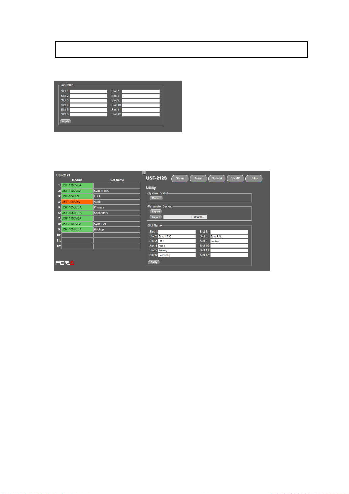
Slot Name
Any name up to 15 characters can be given to Slots 1 to 12. (Half-width and Full-width characters)
The set name is displayed in the pane under Slot Name.
Slot names are set.
33
Page 34
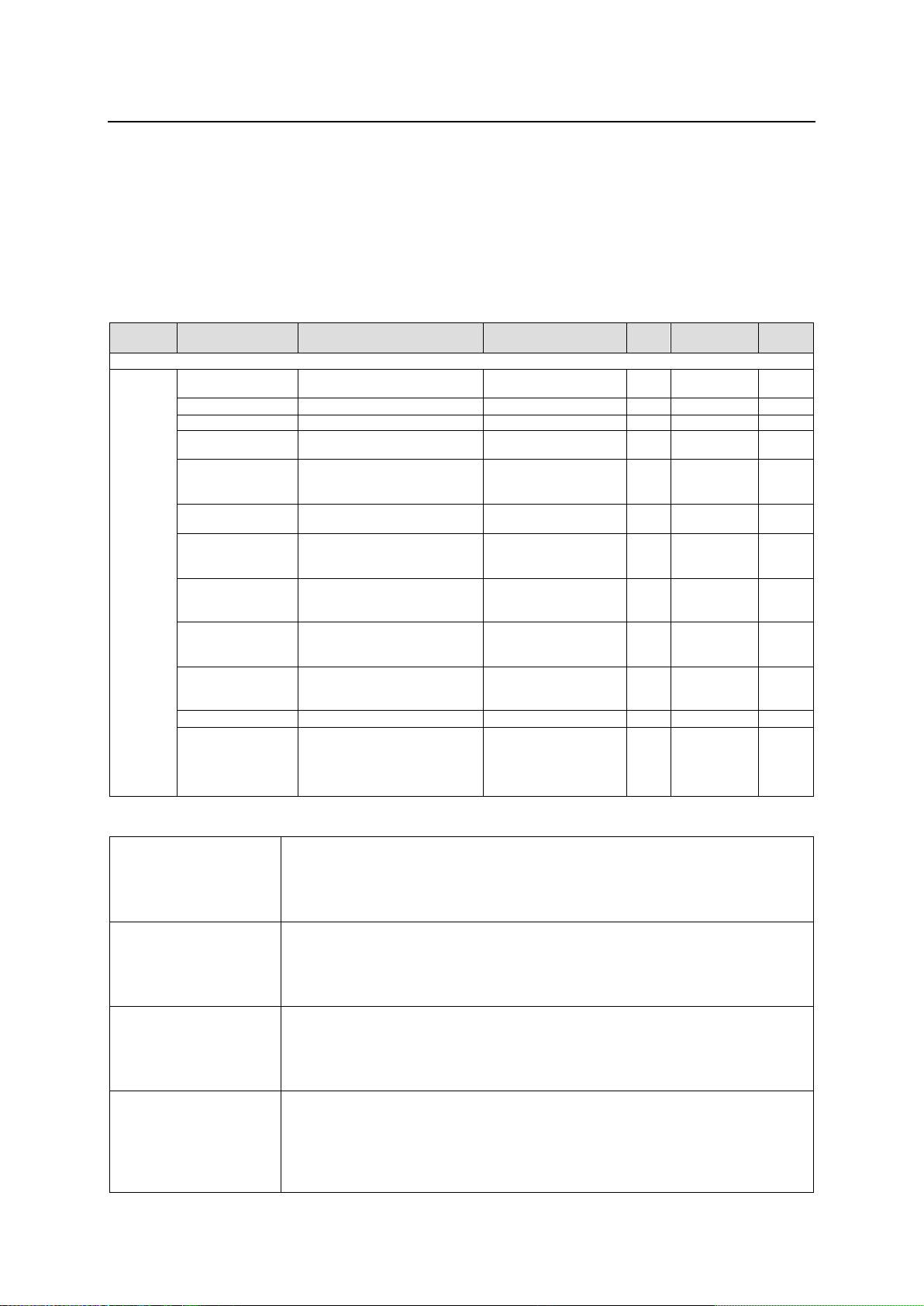
11. About SNMP
Object
group
Item Name
Object name in MIB file
Value
OID
Type
TRAP
Function
OID: 1.3.6.1.4.1.20175.1.310.1.
Unit Status
Product Name
usf212SProductName
USF-212S
1
OCTET
STRING
Product Code
usf212SProductCode
1023809
2
INTEGER
Serial Number
usf212SerialNumber
1596****
3
INTEGER
Soft Ver
usf212SVersion
**.**
4
OCTET
STRING
Power Unit1
Detection
usf212SPowerUnit1Detection
-1:notInstalled
0:notDetected
1:detected
5
INTEGER
Power Unit1 DC
Output
usf212SPowerUnit1DcStatus
-1:notInstalled 0:normal
1:abnormal
6
INTEGER
Power Unit1 FAN
Status
usf212SPowerUnit1FanStatus
-1:notInstalled
0:normal
1:stopped
7
INTEGER
Power Unit2
Detection
usf212SPowerUnit2Detection
-1:notInstalled
0:notDetected
1:detected
8
INTEGER
Power Unit2 DC
Output
usf212SPowerUnit2DcStatus
-1:notInstalled
0:normal
1:abnormal
9
INTEGER
Power Unit2 FAN
Status
usf212SPowerUnit2FanStatus
-1:notInstalled
0:normal
1:stopped
10
INTEGER
Card Temperature
usf212SCardTemperature
**degree Celsius
11
INTEGER
Front FAN Status
usf212SFrontFanStatus
0:normal
1:stopped
fan1 Stopped (Bit0) fan2
Stopped (Bit1) fan3
Stopped (Bit2)
12
INTEGER
Power Unit 1
Detection
Obtains the Power Unit 1 status.
normal: Indicates Power Unit 1 output is normal.
abnormal: Indicates Power Unit 1 output is not detected.
notInstalled: Indicates Power Unit 1 is not installed when turned on.
Power Unit 1 DC
Output
Obtains the Power Unit 1 DC output status.
normal: Indicates Power Unit 1 DC output is normal.
abnormal: Indicates Power Unit 1 DC output is abnormal.
notInstalled: Indicates Power Unit 1 is not installed when turned on.
Power Unit 1 FAN
Status
Obtains the Power Unit 1 FAN status.
normal: Indicates the FAN DC output is normal.
stopped: Indicates the FAN DC output is abnormal.
notInstalled: Indicates Power Unit 1 is not installed when turned on.
Power Unit 2
Detection
Obtains the Power Unit 2 status.
normal: Indicates Power Unit 2 output is normal.
abnormal: Indicates Power Unit 2 output is not detected.
notInstalled: Indicates Power Unit 2 is not installed at the point of powered
on.
The USF-212S can be remotely monitored using an SNMP monitoring system that supports SNMPv2C.
Since functions between the USF-212 and USF-212S are different, refer to the SNMP function
descriptions of the unit you are using.
MIB (Management Information Base) files required for SNMP monitoring system can be downloaded
from Web GUI. Refer to Sec. 10-3. "Network Tab" for details on downloading MIB files and SNMP
settings.
GET List
* No item can be set through SNMP.
34
Page 35
Power Unit 2 DC
Output
Obtains the Power Unit 2 DC status.
normal: Indicates Power Unit 2 DC output is normal.
abnormal: Indicates Power Unit 2 DC output is abnormal.
notInstalled: Indicates Power Unit 2 is not installed when turned on.
Power Unit 2 FAN
Status
Obtains the Power Unit 2 FAN status.
normal: Indicates the FAN DC output is normal.
stopped: Indicates the FAN DC output is abnormal.
notInstalled: Indicates Power Unit 2 is not installed when turned on.
Card Temperature
Obtains the Control Module temperature status.
Front FAN Status
Obtains the USF-212S Front fan status as Bit0 to Bit2. Bit0 to Bit2 indicate
FAN1 to FAN3 states respectively. Each bit indicates 0 when the fan is
operating, and indicates 1 when the fan has stopped.
Object group
Item Name
Object name in MIB file
Value
OID
Type
TRAP
Function
Note
OID : 1.3.6.1.4.1.20175.1.310.1.13.1.
Module
Information
Slot number inserted
usf212SSlotNumber
1 to 12
1. a
INTEGER
Slot inserted status
usf212SSlotStatus
0:moduleIn
1:noModule
2. a
INTEGER
Slot installed module
name
usf212SSlotModuleName
**********
3. a
OCTET
STRING
Object
group
Item Name
Object name in MIB file
OID
Type
Reference Object
TRAP
Power Supply Unit1
Detection Change
usf212SPowerUnit1DetectionChanged
1
INTEGER
usf212PowerUnit1Detection
Power Supply Unit1 DC
Output Status Change
usf212SPowerUnit1DcStatusChanged
2
INTEGER
usf212PowerUnit1DcStatus
Power Supply Unit1 FAN
Status Change
usf212SPowerUnit1FanStatusChanged
3
INTEGER
usf212PowerUnit1FanStatus
Power Supply Unit2
Detection Change
usf212SPowerUnit2DetectionChanged
4
INTEGER
usf212PowerUnit2Detection
Power Supply Unit2 DC
Output Status Change
usf212SPowerUnit2DcStatusChanged
5
INTEGER
usf212PowerUnit2DcStatus
Power Supply Unit2 FAN
Status Change
usf212SPowerUnit2FanStatusChanged
6
INTEGER
usf212PowerUnit2FanStatus
Front FAN Status Change
usf212SFrontFanStatusChanged
8
INTEGER
usf212SFrontFanStatus
Module Status Change
usf212SSlotStatusChanged
11
INTEGER
usf212SSlotNumber
usf212SSlotStatus
Power Supply Unit1
Detection Change
Trap command transmitted when the usf212PowerUnit1Detection
changes.
Power Supply Unit1 Status
Change
Trap command transmitted when the usf212PowerUnit1DcStatus
changes.
Power Supply Unit2
Detection Change
Trap command transmitted when the usf212PowerUnit2Detection
changes.
Power Supply Unit2 Status
Change
Trap command transmitted when the usf212PowerUnit2DcStatus
changes.
Front FAN Status Change
Trap command transmitted when the usf212SFrontFanStatus changes.
Module Status Change
Trap command transmitted when a slot module communication status
changes.
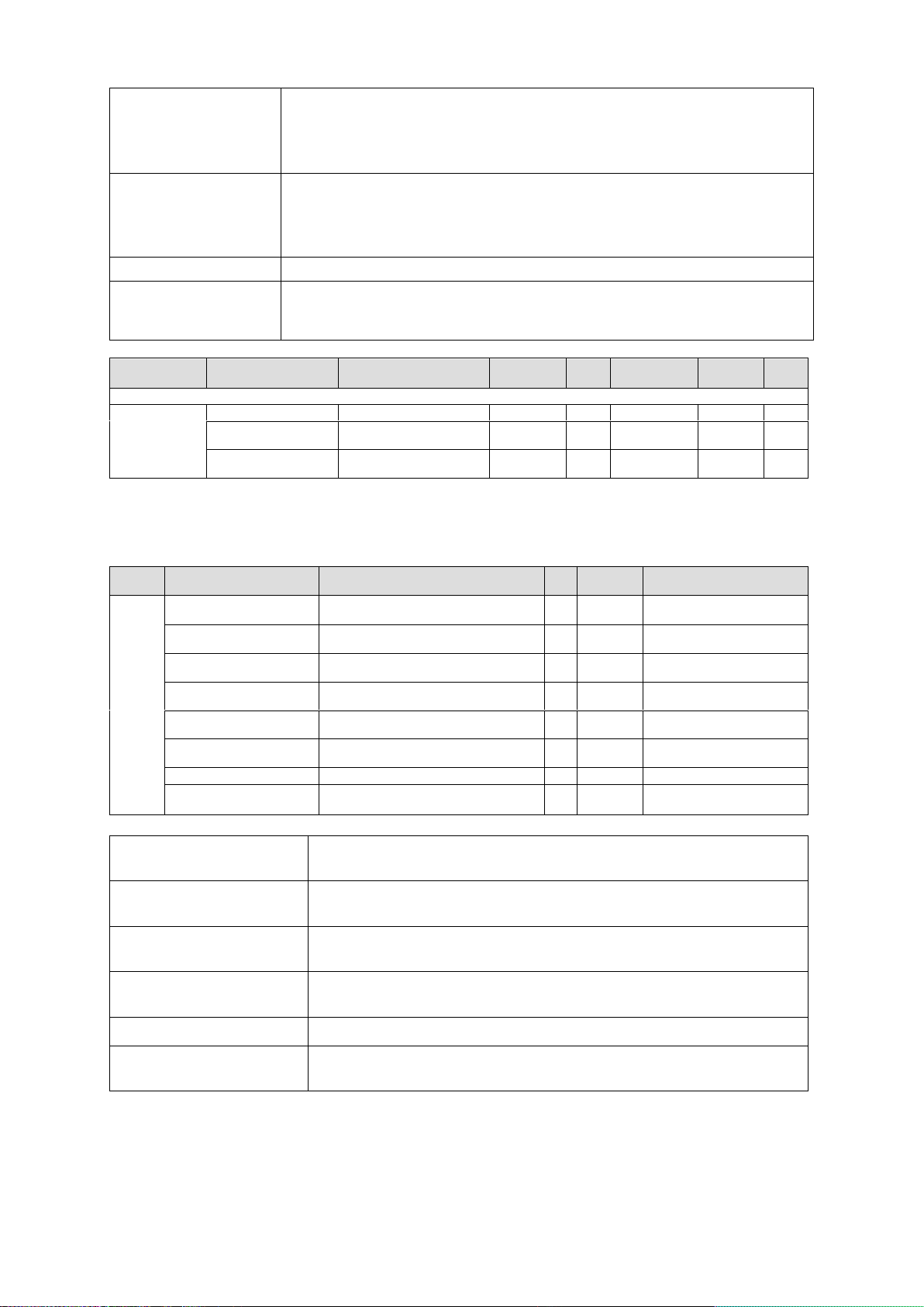
* Letter "a" represents slot number 1 to 12.
* Module
TRAP List
35
Page 36

12. Specifications and Dimensions
Number of Modules
Max. 12
Genlok Input
BB: 0.429Vp-p (NTSC)/0.45Vp-p (PAL) or
Tri-level Sync: 0.6Vp-p
2 inputs: 75Ω BNC x 1 and Loop-through BNC x 1 for each
(Terminate with 75Ω terminator, if unused.)
Interface
Ethernet
100BASE-TX / 1000BASE-T RJ-45 x 2 (LAN 1, LAN 2)
100BASE-TX RJ-45 x 1 (LAN A)
GPI
9-pin D-sub Female
Temperature
0°C to 40°C
Humidity
30% to 90% (no condensation)
Power
100 to 240 V AC ±10%, 50/60 Hz
Power Consumption
670VA (at 100 to 120V AC at maximum output current)
660VA (at 220 to 240V AC at maximum output current)
Dimensions
440 (W) x 88 (H) x 401 (D) mm
Weight
10 kg (Including 1 unit of power supply)
Consumables
(Recommended replacement timespans at room temperature for 24 hour operation)
Power unit: Within 5 years
Cooling fan: Within 6 years
Power Supply
100 to 240 V AC 50/60Hz
Power Consumption
670VA (at 100 to 120V AC at maximum output current)
660VA (at 220 to 240V AC at maximum output current)
Maximum Output Current
+12 V DC 58.4 A
Dimensions
68.6 (W) x 41.3 (H) x 397 (D)mm
Weight
2.5 kg
Temperature
0°C to 40°C
Humidity
30% to 90% (no condensation)
12-1. Specifications
12-1-1. USF-212S
12-1-2. USF-212PS
36
Page 37
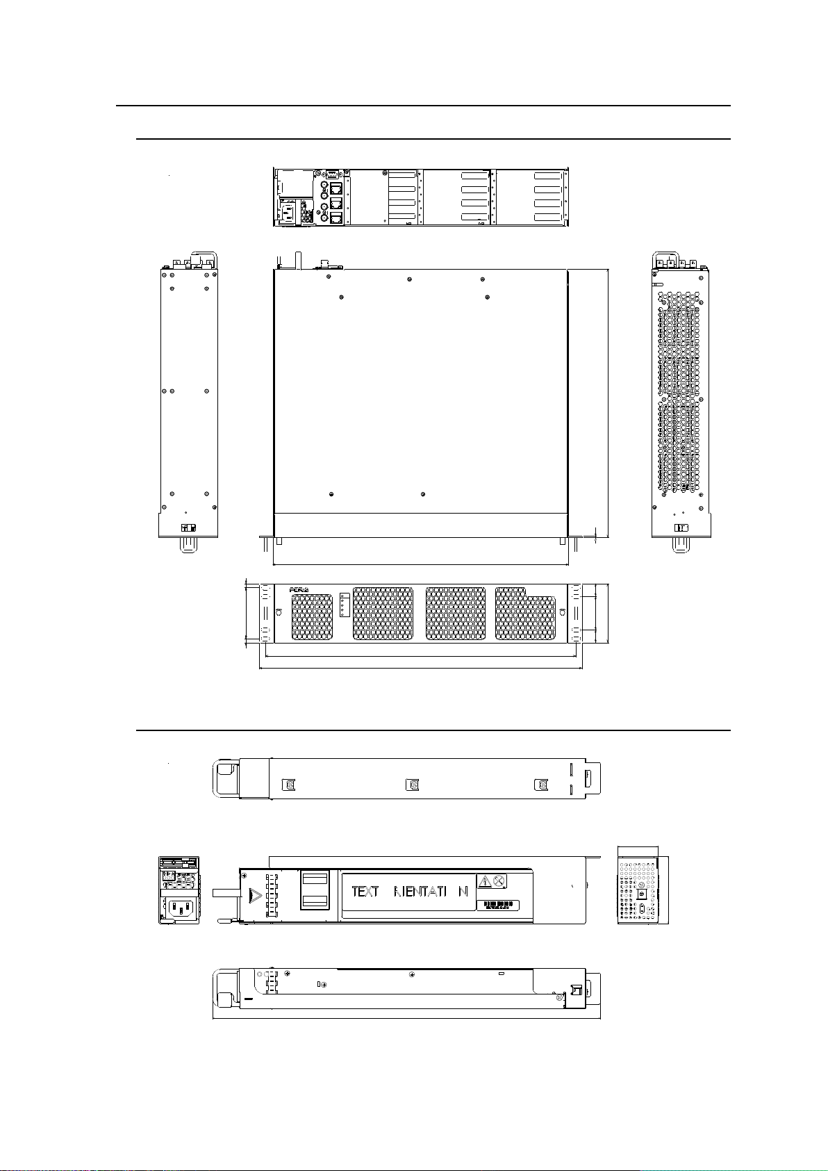
12-2. External Dimensions
UNIVERSAL S YSTEM FRAME
USF-212
LOCK
POWER
ON
ALARM
DC 1
DC 2
FAN
TEMP
LOCK
USF-212
ALARM
LAN A
LAN 2
LAN 1
GENLOCK 2
GENLOCK 1
A
C1
0
0
-2
4
0
V 5
0
/60
H
z IN
2
A
C
10
0
-2
40
V
5
0/6
0
H
z IN
1
462
19
50
19
76
6
6
480
440
88
401
2
P
O
W
E
R
O
N
O
F
F
6
8
.6
41.3
397
12-2-1. USF-212S
(All dimensions in mm.)
12-2-2. USF-212PS
(All dimensions in mm.)
37
Page 38

Page 39

Warning
This equipment has been tested and found to comply with the limits for a
Class A digital device, pursuant to Part 15 of FCC Rules. These limits are
designed to provide reasonable protection against harmful interference
when the equipment is operated in a commercial environment. This
equipment generates, uses, and can radiate radio frequency energy and,
if not installed and used in accordance with the instruction manual, may
cause harmful interference to radio communications. Operation of this
equipment in a residential area is likely to cause harmful interference, in
which case the user will be required to correct the interference at his own
expense.
Page 40

FOR-A COMPANY LIMITED
Head Office 3-8-1 Ebisu, Shibuya-ku, Tokyo 150-0013, Japan
Overseas Division Tel: +81(0)3 3446 3936 Fax: +81(0)3 3446 1470
Japan Branch Offices Osaka/Okinawa/Fukuoka/Hiroshima/Nagoya/Sendai/Sapporo
R&D/Production Sakura Center/Sapporo Center
FOR-A Corporation of America
11155 Knott Ave., Suite G&H, Cypress, CA 90630, USA.
Tel: +1 714 894 3311 Fax: +1 714 894 5399
FOR-A Corporation of America East Coast Office
2 Executive Drive, Suite 670, Fort Lee Executive Park, Fort Lee, NJ 07024, USA
Tel: +1 201 944 1120 Fax: +1 201 944 1132
FOR-A Corporation of America Distribution & Service Center
2400 N.E. Waldo Road, Gainesville, FL 32609, USA
Tel: +1 352 371 1505 Fax: +1 352 378 5320
FOR-A Corporation of America Miami Office
8333 North West 53rd Street Suite 427 Doral, FL 33166, USA
Tel: +1 305 931 1700 Fax: +1 714 894 5399
FOR-A Corporation of Canada
1131A, Leslie Street Suite 209, Toronto, Ontario M3C 2J6, Canada
Tel: +1 416 977 0343 Fax: +1 416 977 0657
FOR-A Europe S.r.l.
Via Volturno 37, 20861 Brugherio MB, Italy
Tel: +39 039 91 64 811 Fax: +39 039 878 140
FOR A UK Limited
Trident Court, 1 Oakcroft Road, Chessington, KT9 1BD, UK
Tel: +44 (0)20 3044 2935 Fax: +44(0)20 3044 2936
FOR-A Italia S.r.l.
Via Volturno 37, 20861 Brugherio MB, Italy
Tel: +39 039 881 086/103 Fax: +39 039 878 140
FOR-A Corporation of Korea
1007, 57-5, Yangsan-ro, Yeongdeungpo-gu, Seoul 150-103, Korea
Tel: +82 (0)2 2637 0761 Fax: +82 (0)2 2637 0760
FOR-A China Limited
708B Huateng Building, No. 302, 3 District, Jinsong, Chaoyang, Beijing 100021, China
Tel: +86 (0)10 8721 6023 Fax: +86 (0)10 8721 6033
FOR-A Middle East-Africa Office
Dubai Media City, Aurora Tower, Office 1407, P.O. Box 502688, Dubai, UAE
Tel: +971 (0)4 551 5830 Fax: +971 (0)4 551 5832
Agiv (India) Private Limited (FOR-A India)
2nd Floor, Valecha Chambers, Link Road, Andheri(W), Mumbai 400053
Tel: +91-22-26733623 Fax: +91-22-26393415
December 28, 2016 Printed in Japan
http://www.for-a.com/
 Loading...