

Page 1

OPERATION
MANUAL
USF-105DADA
Digital Audio Distribution Amplifier
1st Edition
Page 2
Precautions
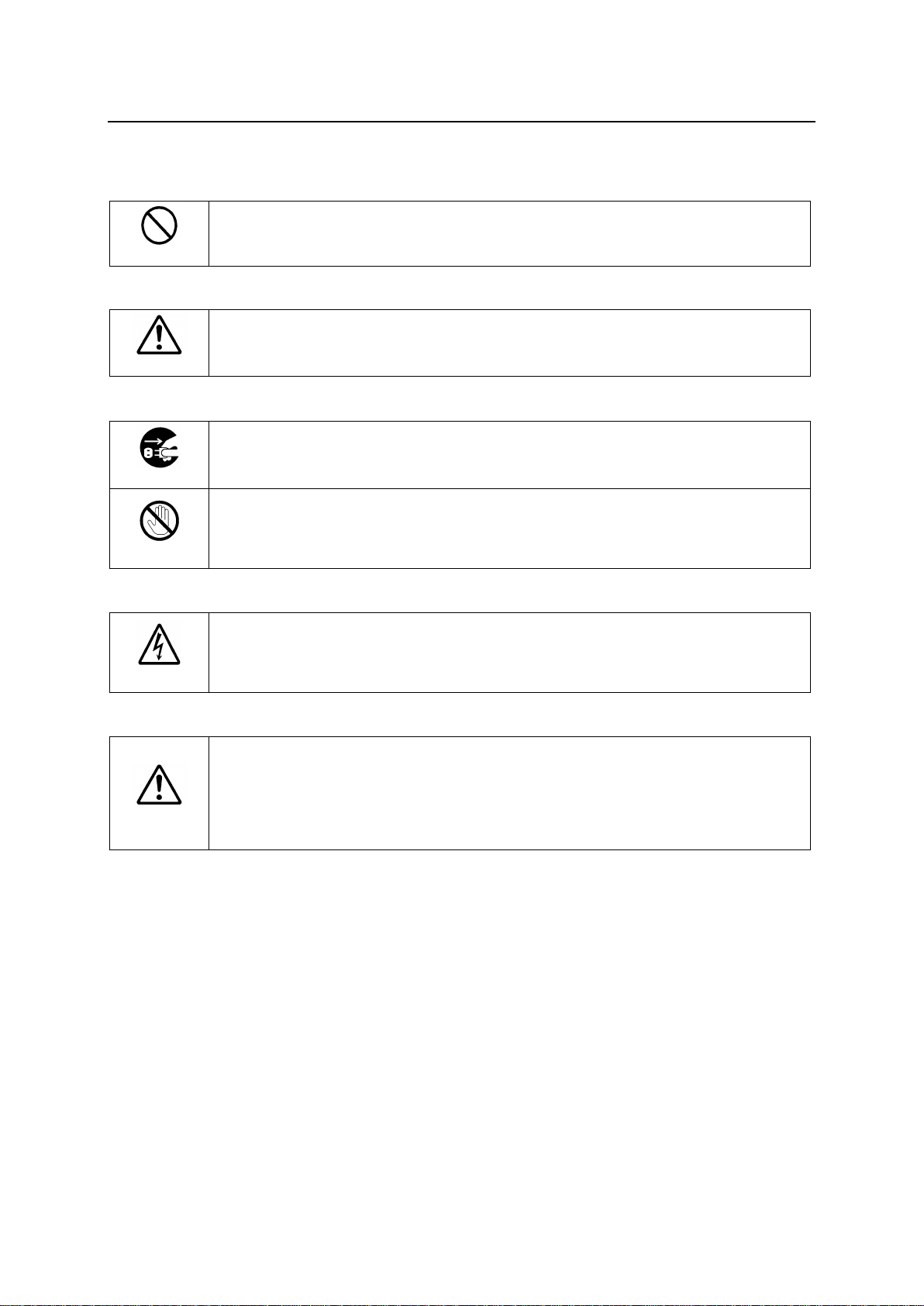
Stop
Do not place the unit in the place of high temperature and high humidity, dusty, or high
vibrations. Operation other than the operating environment conditions may cause
malfunction, fire, or electrical shock.
Caution
Handle with care to avoid impact shock during transit, which may cause malfunction.
When you need to transport the unit, use the original or suitable alternative packing
material.
Caution
Do not remove covers, panels, casing, or access the circuitry with power applied to the
unit. Turn the power off and disconnect the power cord prior to removal. Internal
servicing / adjustment of unit should only be performed by qualified personnel.
Stop
Do not touch any parts / circuitry with a high heat factor.
Capacitors can retain enough electric charge to cause mild to serious shock, even after
the power has been disconnected. Capacitors associated with the power supply are
especially hazardous.
Caution
If abnormal odors or noises are noticed coming from the unit, immediately turn the
power off and disconnect the power cord to avoid potentially hazardous conditions. If
problems similar to the above occur, contact an authorized service representative
before attempting to operate the unit again.
Caution
Consumable items that are used in the unit must be periodically replaced. For further
details on which parts are consumables and when they should be replaced, refer to the
specifications at the end of the Operation Manual. Since the service life of the
consumables varies greatly depending on the environment in which they are used,
such items should be replaced at an early date. For details on replacing consumable
items, contact your dealer.
Important Safety Warnings
[Operation]
[Transportation]
[Circuitry Access]
[Potential Hazards]
[Consumables]
2
Page 3

Upon Receipt
ITEM
QTY
REMARKS
USF-105DADA
1 each
USF-105DADA Front module
USF-105DADA Rear module
CD-ROM
1
Operation Manual (PDF)
Screws
4
Rear module installation
USF-105DADA modules and their accessories are fully inspected and adjusted prior to shipment. Check
your received items against the packing lists below. Check to ensure no damage has occurred during
shipment. If damage has occurred, or items are missing, inform your supplier immediately.
USF-105DADA Box
* The USF-105DADA is used by installing into a USF-212 / USF-212S frame.
3
Page 4

Table of Contents
1. 1. Prior to Starting ................................................................................................................................. 5
1-1. Overview ..................................................................................................................................... 5
1-2. Features ...................................................................................................................................... 5
2. Panel Descriptions ................................................................................................................................ 6
2-1. Front Panel .................................................................................................................................. 6
2-2. Rear Panel .................................................................................................................................. 7
3. Switch Settings ..................................................................................................................................... 8
3-1. S1: Reboot ................................................................................................................................. 8
3-2. DS1 Switches 1 and 2: Signal Mode Settings ........................................................................... 8
3-3. DS2 Switches 1 and 2: Signal Mode Settings ........................................................................... 8
3-4. DS2 Switches 3 and 4: Input Signal Switch Settings ................................................................. 8
3-5. DS2 Switch 5, 6, and 7: Internal Bus Switch Output Settings ................................................... 9
3-6. Switch S2: MODE Set ..............................................................................................................10
3-7. Switch S3: TERM Set ................................................................................................................10
4. Signal Mode Settings ..........................................................................................................................11
4-1. When Signal Mode Is Correctly Set ..........................................................................................12
4-2. When Signal Mode Is NOT Set correctly ..................................................................................13
5. Output Gain Adjustment .....................................................................................................................13
6. Input Signal Detection ........................................................................................................................13
7. Web GUI Setup ..................................................................................................................................14
8. SNMP (Simple Network Message Protocol) Function ........................................................................16
9. Extended Distribution Using Multiple USF-105DADAs ......................................................................17
9-1. Settings to Distribute 10 Output Signals from 1 Input ...............................................................18
9-2. Settings to Distribute 15 Output Signals from 1 Input ...............................................................19
9-3. Settings to Distribute 20 Output Signals from 1 Input ...............................................................20
10. Specifications and Dimensions ........................................................................................................21
10-1. Unit Specifications ...................................................................................................................21
10-2. External Dimensions ...............................................................................................................21
4
Page 5

1. 1. Prior to Starting
1-1. Overview
The USF-105DADA is a digital audio distribution amplifier that can be installed in a USF frame. The
USF-105DADA supports AES/EBU signals and is capable of producing up to 5 outputs from 1
input.
LTS and Word Clock signals can be supported by changing the signal mode.
Distribution numbers can be extended using multiple USF-105DADAs.
1-2. Features
Installs into USF frames
1 input 5 distribution outputs
Supports AES/EBU, LTC or Word Clock signals for 5 distribution outputs
Audio output gain adjustable per Out port for LTC or Word Clock signal distribution
SNMP monitoring available (when installed into a USF-212S frame)
Up to 4 USF-105DADA can be installed to extend distribution up to 20 outputs.
Limitation on installation methods may apply.
5
Page 6
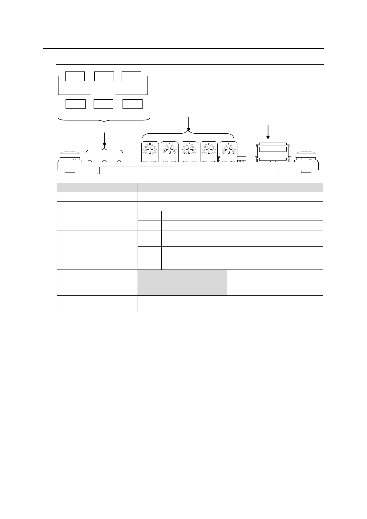
2. Panel Descriptions
USF-105DADA
No.
Name
Description
(1)
POWER LED
Lights green when normal DC power is supplied by USF frame.
(2)
INPUT LED
*1
Lights when input signal is detected.
(3)
TERM LED
On
Input signal impedance is set to 75Ω.
Off
Input signal impedance is set to 1kΩ.
(4)
MODE LED
On
LEDs to confirm signal mode. One of the LED from AES,
LTC, or WC is lit to indicate current signal mode.
Flash
or
Off
When LEDs are flashing or all LEDs are turned off, card
switches are incorrectly set. See Sec. 4 “Signal Mode
Settings” for correct switch settings.
(5)
OUTPUT GAIN
OUT1 to OUT5
LTC/
Word Clock Distribution Mode
About ±3.0dB of gain adjustment
is available per output port.
AES Distribution Mode
Output gain is not adjustable.
(6)
USB Connector
Used for USF-105DADA software version upgrades.
(Do not connect a USB device.)
(5)
(6)
(1) to (4)
AES
LTC WC
POWER
MODE
INPUT
TERM
2-1. Front Panel
*1
Input is not detected when input signal is distributed via USF-212/212S Internal Bus.
INPUT LED turns off.
6
Page 7
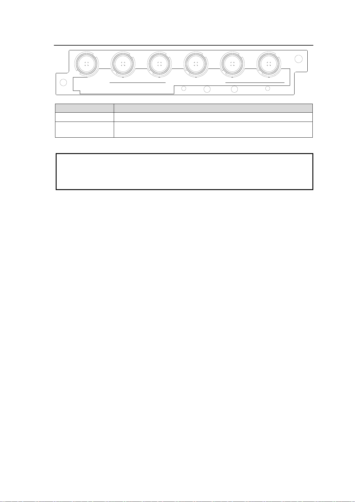
2-2. Rear Panel
DIGITAL
AUDIO IN
USF-105DADA
1 2 3 4 5
DIGITAL AUDIO OUT
Name
Description
DIGITAL AUDIO IN
Input port. Signals compliant with the selected signal mode are input.
DIGITAL AUDIO
OUT 1 - 5
Output port. Distributes 5 outputs from signals that are input in DIGITAL
AUDIO IN.
IMPORTANT
Maximum 7.5Vp-p signal is output from a DIGITAL AUDIO OUT port. Check that the signal mode
is set correctly and the output signal level meets the equivalent level of a connecting device to
prevent damage to the device. Change the signal mode after dis-connecting the DIGITAL
AUDIO OUT port, then check the output signal level before re-connection. If the signal mode has
been incorrectly set, no distribution signal is output. (See Sec. 4 “Signal Mode Setting”)
7
Page 8
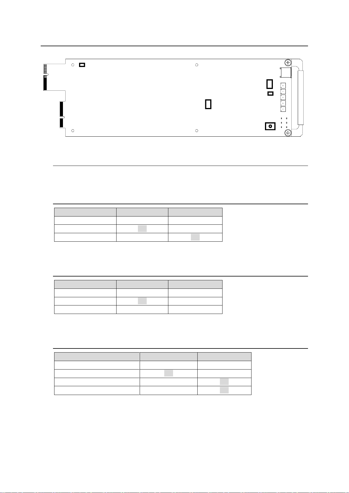
3. Switch Settings
Operation Mode
Switch 1Setting
Switch 2 Setting
AES (Default)
OFF
OFF
LTC
ON
OFF
Word Clock
OFF
ON
Signal Mode
Switch 1 Setting
Switch 2 Setting
AES (Default)
OFF
OFF
LTC
ON
OFF
Word Clock
OFF
ON
Input Signal Selection
Switch 3 Setting
Switch 4 Setting
Rear BNC Input (Default)
OFF
OFF
Internal Bus Signal 1
ON
OFF
Internal Bus Signal 2
OFF
ON
Internal Bus Signal 3
ON
ON
DS1
S2
S1
S3
DS2
Switch Locations
3-1. S1: Reboot
Power Reboot switch. Pressing the switch for 1 second starts rebooting the unit.
3-2. DS1 Switches 1 and 2: Signal Mode Settings
Do not change Switch 3 to 8 settings. Leave them OFF.
3-3. DS2 Switches 1 and 2: Signal Mode Settings
Do not change the Switch 8 setting. Leave it OFF.
3-4. DS2 Switches 3 and 4: Input Signal Switch Settings
* Internal Bus Signals 1 to 3 are used to increase distribution by installing multiple
USF-105DADAs.
8
Page 9
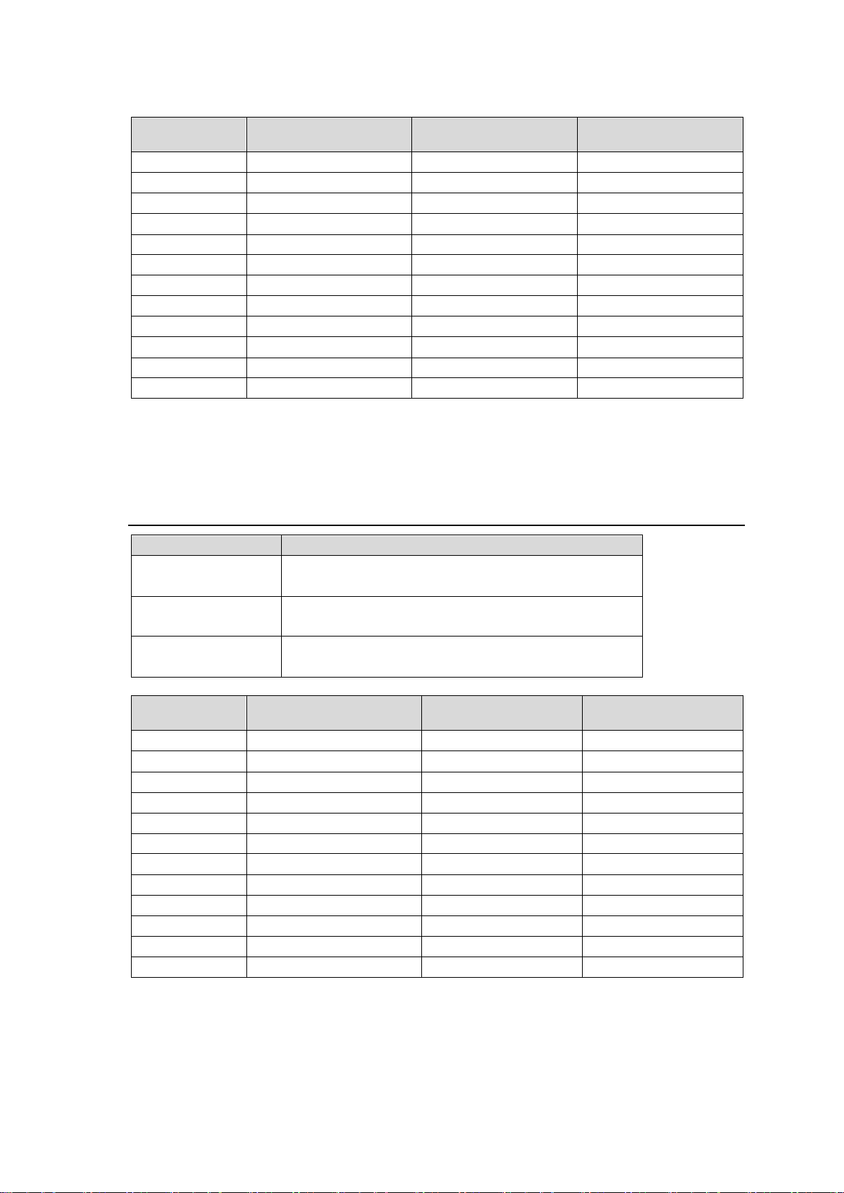
Internal Bus Signal 1 to 3 varies according to the slot number in which the USF-105DADA is
Installed Slot
No.
Internal Bus Signal 1
Internal Bus Signal 2
Internal Bus Signal 3
1
Output from Slot 2
Output from Slot 3
Output from Slot 4
2
Output from Slot 1
Output from Slot 3
Output from Slot 4
3
Output from Slot 4
Output from Slot 2
Output from Slot 1
4
Output from Slot 3
Output from Slot 2
Output from Slot 1
5
Output from Slot 6
Output from Slot 7
Output from Slot 8
6
Output from Slot 5
Output from Slot 7
Output from Slot 8
7
Output from Slot 8
Output from Slot 6
Output from Slot 5
8
Output from Slot 7
Output from Slot 6
Output from Slot 5
9
Output from Slot 10
Output from Slot 11
Output from Slot 12
10
Output from Slot 9
Output from Slot 11
Output from Slot 12
11
Output from Slot 12
Output from Slot 10
Output from Slot 9
12
Output from Slot 11
Output from Slot 10
Output from Slot 9
DS2
Internal Bus Output Setting
Switch 5 Setting
ON: Outputs to Internal Bus 1.
OFF: Does not output to Internal Bus 1. (Default)
Switch 6 Setting
ON: Outputs to Internal Bus 2.
OFF: Does not output to Internal Bus 2. (Default)
Switch 7 Setting
ON: Outputs to Internal Bus 3.
OFF: Does not output to Internal Bus 3. (Default)
Installed Slot
No.
Internal Bus Signal 1
Internal Bus Signal 2
Internal Bus Signal 3
1
Output to Slot 2
Output to Slot 3
Output to Slot 4
2
Output to Slot 1
Output to Slot 3
Output to Slot 4
3
Output to Slot 4
Output to Slot 2
Output to Slot 1
4
Output to Slot 3
Output to Slot 2
Output to Slot 1
5
Output to Slot 6
Output to Slot 7
Output to Slot 8
6
Output to Slot 5
Output to Slot 7
Output to Slot 8
7
Output to Slot 8
Output to Slot 6
Output to Slot 5
8
Output to Slot 7
Output to Slot 6
Output to Slot 5
9
Output to Slot 10
Output to Slot 11
Output to Slot 12
10
Output to Slot 9
Output to Slot 11
Output to Slot 12
11
Output to Slot 12
Output to Slot 10
Output to Slot 9
12
Output to Slot 11
Output to Slot 10
Output to Slot 9
installed. See the table below for details.
* When distributing signals from an Internal Bus, USF-105DADA Internal Bus output signals
should be set to “Enable.” Do not change Switch 8 setting. Keep it OFF.
3-5. DS2 Switch 5, 6, and 7: Internal Bus Switch Output
Settings
9
Page 10
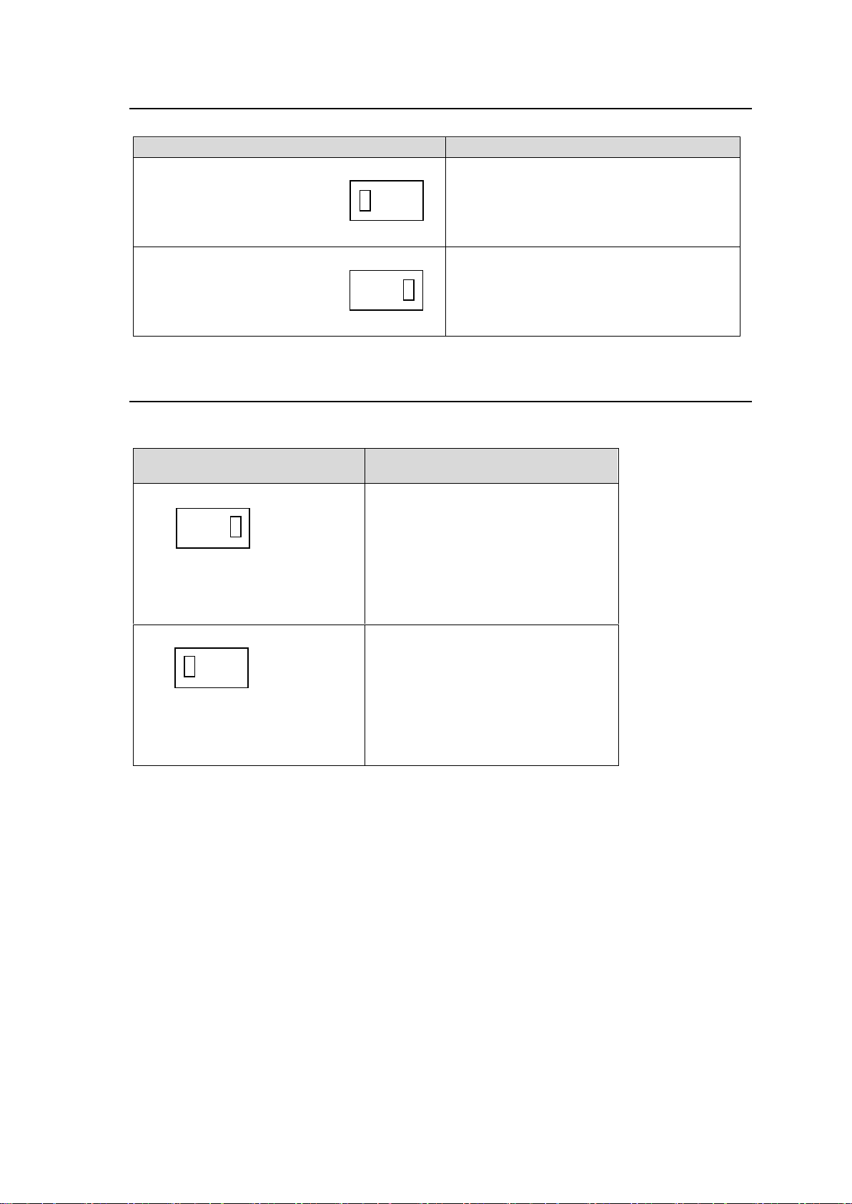
3-6. Switch S2: MODE Set
Setting
Distribution Mode Settings
AES distribution mode (Default)
Set the switch toward AES.
LTC distribution mode / Word Clock
distribution mode
Set the switch toward LTC/WC.
Setting
Input Signal Impedance and
Distribution Mode Settings
Set impedance to 75Ω (default) in
AES distribution mode.
Set impedance to 1kΩ in LTC / Word
Clock distribution mode.
6
4
1
3
S2:MODE SET
1 ⇔ 3
AES LTC/WC
6
4
1
3
S2:MODE SET
1 ⇔ 3
AES LTC/WC
3 1 4
6
S3:TERM SET
3 ⇔ 1
1KΩ 75Ω
3 1 4
6
S3:TERM SET
3 ⇔ 1
1KΩ 75Ω
Sets distribution mode settings.
3-7. Switch S3: TERM Set
Sets input signal impedance.
Adjusts with input signal impedance in USF-105DADA.
10
Page 11
4. Signal Mode Settings
AES Distribution Mode
Inputs and distributes digital audio signals.
Inputs AES/EBU signals with sample frequencies from 32 to 96KHz.
* Gain is not adjustable using the front panel.
LTC Distribution Mode
Inputs and distributes LTC signals.
Inputs LTC signal as signal input.
Gain is adjustable using the front panel.
(Adjustable gain range: Approx. ±3.0dB)
Word Clock Distribution
Mode
Inputs and distributes Word Clock signals.
Gain is adjustable using the front panel.
(Adjustable gain range: Approx. ±3.0dB)
After changing the Distribution Mode…
Outputs signal level changes according to the distribution mode. Before connecting a device, check
that the distribution mode is set correctly and the output signal level meets the equivalent level of a
connecting device to prevent damage to the device.
AES Distribution Mode Setting
DS1 Switch 1
OFF
DS1 Switch 2
OFF
DS2 Switch 1
OFF
DS2 Switch 2
OFF
S2 Switch
Set the switch toward AES.
S3 Switch
Set impedance to 75Ω (default).
3
1
4
6
S3:TERM SET
3 ⇔ 1
1KΩ 75Ω
6 4 1
3
S2:MODE SET
1 ⇔ 3
AES LTC/WC
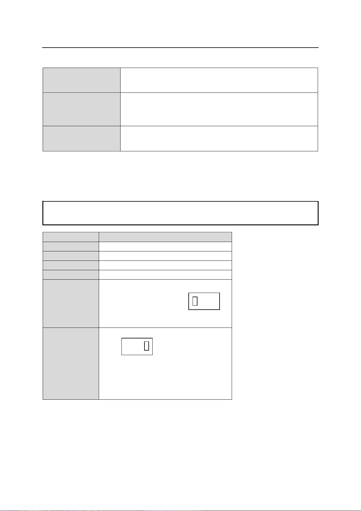
Three signal modes are available using USF-105DADA.
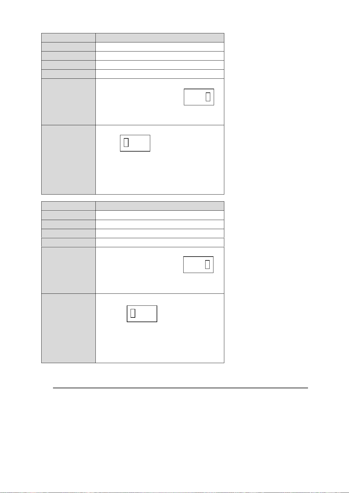
Sets distribution mode according to the signal input referring to illustrations in the table below. (Default:
AES distribution mode)
Sets distribution mode using DS1, DS2, S2, and S3 switches on the card. See Sec. 3 “Switch Settings”
for switch locations.
11
Page 12
LTC Distribution Mode Setting
DS1 Switch 1
ON
DS1 Switch 2
OFF
DS2 Switch 1
ON
DS2 Switch 2
OFF
S2 Switch
Set the switch toward LTC/WC.
S3 Switch
Set impedance to 1kΩ.
Word Clock Distribution Mode Setting
DS1 Switch 1
OFF
DS1 Switch 2
ON
DS2 Switch 1
OFF
DS2 Switch 2
ON
S2 Switch
Set the switch toward LTC/WC.
S3 Switch
Set impedance to 1kΩ.
3 1 4
6
S3:TERM SET
3 ⇔ 1
1KΩ 75Ω
3 1 4
6
S3:TERM SET
3 ⇔ 1
1KΩ 75Ω
6 4 1
3
S2:MODE SET
1 ⇔ 3
AES LTC/WC
6
4
1
3
S2:MODE SET
1 ⇔ 3
AES LTC/WC
4-1. When Signal Mode Is Correctly Set
MODE LED on the front panel lights when power is turned on after installing a USF-105DADA into
a USF frame. Confirm that the LED of your selected distribution mode is lit.
When a USF-105DADA is installed in a USF-212S, Board Settings in Web GUI are indicated as
Correct.
12
Page 13
4-2. When Signal Mode Is NOT Set correctly
AES Distribution Mode
Digital audio input signal is detected when the sample frequency is from
32 to 96kHz. If a signal with a sample frequency different from 32 to 96kHz
is input, 0V is output from the DIGITAL AUDIO OUT port.
LTC Distribution Mode
For an LTC input signal, if a signal with a frequency different from about
950Hz to 13kHz is input, 0V is output from the DIGITAL AUDIO OUT port.
Word Clock Distribution
Mode
For a Word Clock input signal, if a signal with a frequency different from
about 31kHz to 200 kHz is input, 0V is output from DIGITAL AUDIO OUT
port.
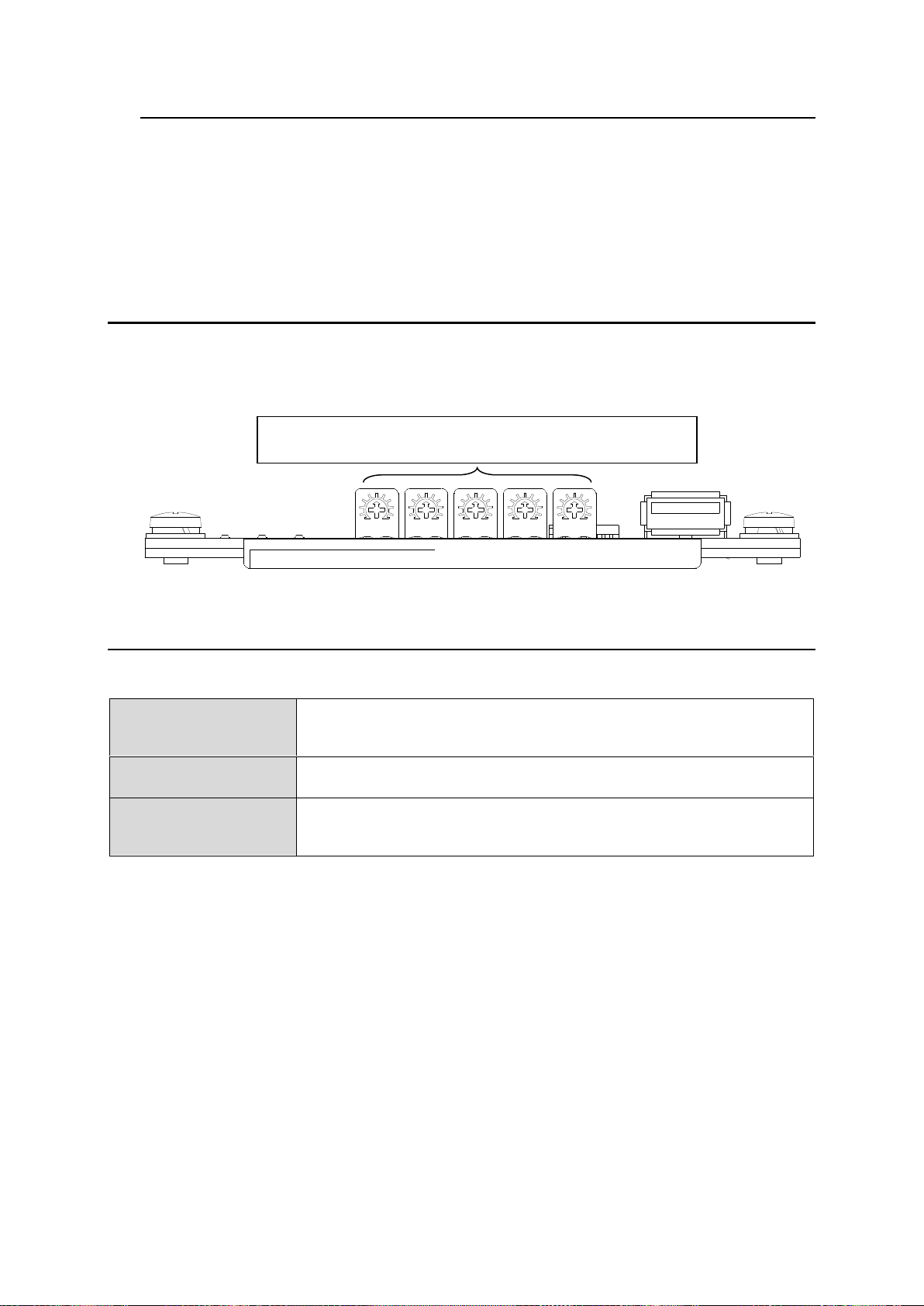
USF-105DADA
Volume controllers for output gain adjustment.
Outputs 1 to 5 are adjusted in order from the left controller.
MODE LED on the front panel flashes or turned off when power is turned on after installing a
USF-105DADA into a USF frame.
When a USF-105DADA is installed in a USF-212S, Board Settings in Web GUI are indicated as
Incorrect (Check FRONT CARD. S2, S3, DS1 and DS2 settings.). See Sec. 7 “Web GUI” for
details.
The output port is fixed to 0V. See Sec. 2-2 “Rear Panel” for details on output port details.
5. Output Gain Adjustment
When USF-105DADA distribution is in LTC or Word Clock mode, output gain can be adjusted using front
panel volume controllers. Gain adjustment is available for output ports 1 to 5 respectively.
Adjustment ranges from -3dB to +3dB.
6. Input Signal Detection
USF-105DADA signal detection differs with the distribution mode.
13
Page 14
7. Web GUI Setup
Item
Description
Slot
Installed slot number of USF-212S
S/N
USF-105DADA serial number
MAC Address
USF-105DADA MAC address
Software Version
USF-105DADA software version
FPGA Version
USF-105DADA FPGA version
IP Address
USF-105DADA IP address
Installed Cards
Installed cards matching
Matched: Matched cards are installed.
Mismatched: A mismatched rear card is installed. Install a correct rear card.
CPU Temperature
CPU temperature on the USF-105DADA
Input
Input signal condition
Detected: Signal is correctly input.
Not Detected: Input signal is not detected.
See Sec.5 “Input Signal Detection” for details.
* When an input signal is set to be input other than via a rear BNC connector, the
input signal is not detected and “------“ is indicated.
Input Status Trap
When monitoring using SNMP Manager,
Enable: Sends input status trap
Disable: Not send input status trap
* When an input signal is set to be input other than via a rear BNC connector, the
input signal is not detected and a trap is not sent out.
See Sec. 5 “Input Signal Detection” for trap sending conditions. See
Sec. 8 ”SNMP (Simple Network Message Protocol) Function” for trap details.
Signal Mode
USF-105DADA signal mode
See Sec. 4 “Signal Mode Setting” for details.
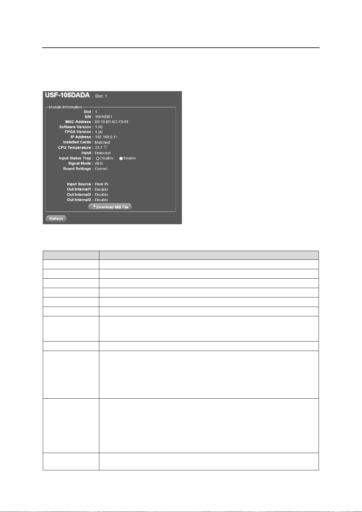
Web GUI can be displayed when a USF-105DADA is installed into a USF-212S frame, but is not
displayed when it is installed into a USF-212 frame. See USF-212S operation manual for details on
displaying a Web GUI.
Launch Web GUI and click USF-105DADA from slot no.1 to 12 of the USF-212S. The screen below
opens.
Module Information
14
Page 15
Item
Description
Board Settings
Correct: Signal mode is correctly set.
Incorrect (Check FRONT CARD. S2, S3, DS1 and DS2 settings.): Signal mode
is incorrectly set. See Sec.4 “Signal Mode Setting” and set the mode correctly.
When signal mode is incorrectly set, signal is not output.
Input Source
Input Signal that gets distributed.
Rear IN: Input signal via rear panel BNC “DIGITAL AUDIO IN”
Slot1 - 12: Input signal via internal USF frame bus.
Out Internal1 to 3
Signal output status to USF frame Internal Bus.
Disable: Internal bus is not used.
Slot 1 - 12: Signal is output via frame Internal Bus to the indicated slot number
module. See Sec.9 “Extended Distribution Using Multiple USF-105DADA” for
details on output extension using internal buses.
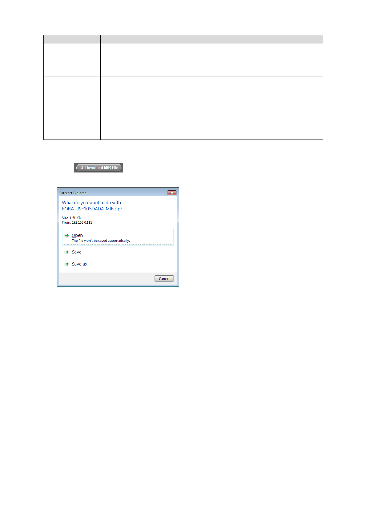
Downloading MIB Files
(1) Click to download the MIB (Management Information Base) for your SNMP
manager.
(2) Select Save (S) from the opened dialog box.
んb
(3) FORA-USF105DADA-MIB.zip File is downloaded.
(4) Unzip the file and load it into your SNMP manager.
15
Page 16
8. SNMP (Simple Network Message Protocol) Function
Category
Object name
Object name in MIB file
Value
OID
Type
Trap
OID : 1.3.6.1.4.1.20175.1.332.1.
Unit
information
Product Name
usf105DadaProductName
USF-105DADA
1
OCTET
STRING
Product Code
usf105DadaProductCode
1023828
2
INTEGER
Serial Number
usf105DadaSerialNumber
1684****
3
INTEGER
Soft Version
usf105DadaVersion
**.**
4
OCTET
STRING
FPGA Version
usf105DadaFpgaVersion
**.**
5
OCTET
STRING
Slot Number
usf105DadaSlotNumber
1~12
6
INTEGER
CPU Temperature
usf105DadaCpuTemperature
** degree Celsius
7
INTEGER
Input Status
usf105DadaInputStatus
-1:cannotDetect
0:notDetected
1:detected
8
INTEGER
Signal Mode
usf105DadaModeStatus
0:aes
1:ltc
2:wordClock
9
INTEGER
Board Settings
usf105DadaBoardSettings
0:correct
1: incorrect
10
INTEGER
Input Source
usf105DadaInputSource
0:Rear,
1-12:Slot1-12
11
INTEGER
Out Internal1 Status
usf105DadaOutInternal1
0:Disable
1-12=Slot1-12
12
INTEGER
Out Internal2 Status
usf105DadaOutInternal2
0:Disable
1-12:Slot1-12
13
INTEGER
Out Internal3 Status
usf105DadaOutInternal3
0:Disable
1-12:Slot1-12
14
INTEGER
Object
Group
Item Name
Object name in MIB file
OID
Reference Object
Type
OID : 1.3.6.1.4.1.20175.1.332.0.
TRAP
Input Signal
usf105DadaInputStatusChanged
1
usf105DadaSlotNumber
INTEGER
usf105DadaInputStatus
INTEGER
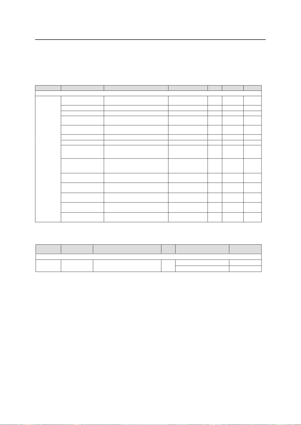
The USF-105DADA can be remotely monitored using the SNMP (Simple Network Message Protocol)
v2C protocol. An MIB (Management Information Base) file required in monitoring can be downloaded
from Web GUI. See “Downloading MIB File” on the previous page.
See the USF-212S Operation Manual for details on SNMP network settings.
GET List
* No item can be set from SNMP.
TRAP List
* Input Signal Trap is not sent when input signal is distributed from USF-212S internal bus.
16
Page 17
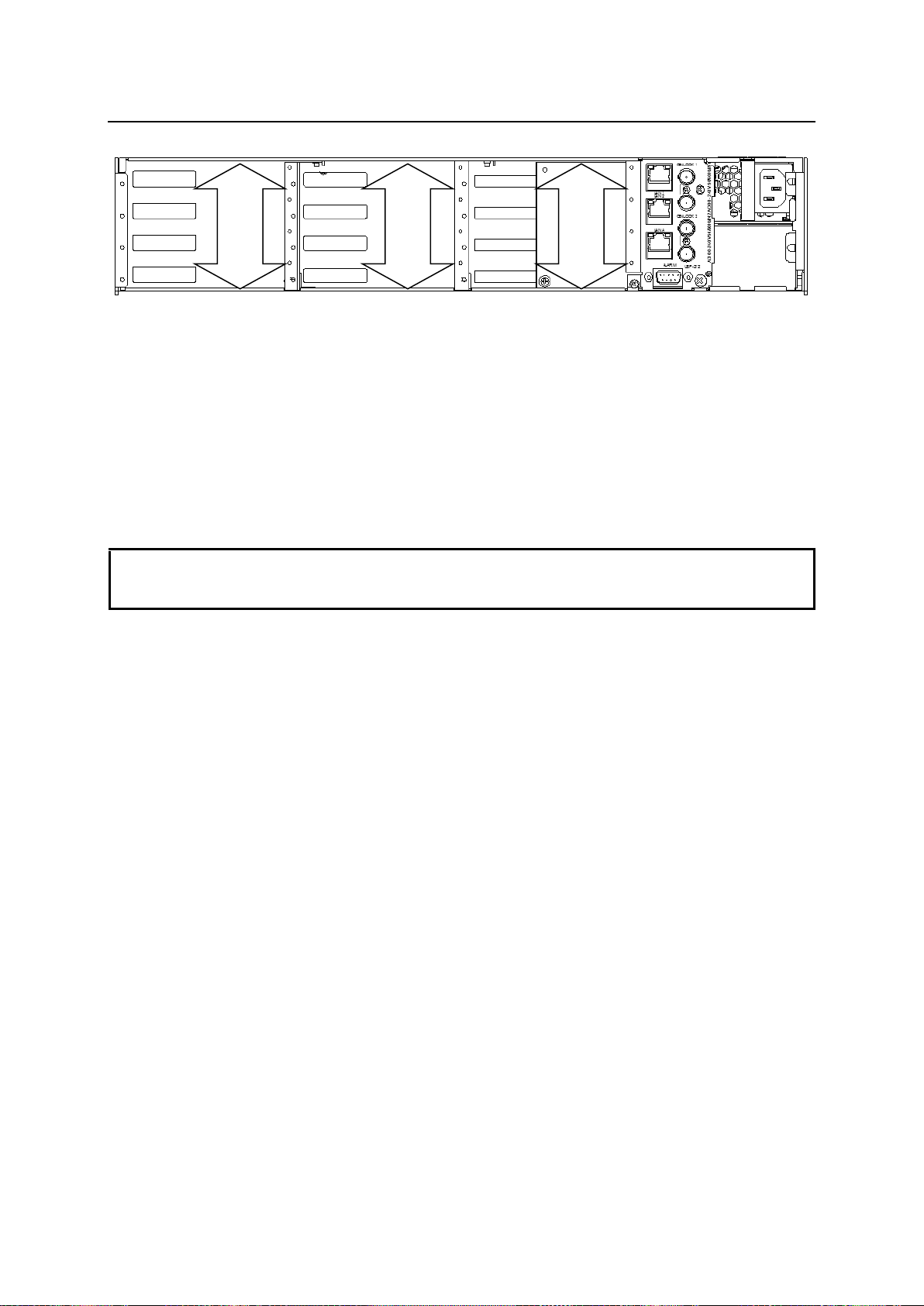
9. Extended Distribution Using Multiple USF-105DADAs
IMPORTANT
When using USF-105DADA units in a USF frame internal bus, apply multiple USF-105DADAs to
extend distributions. Other USF modules cannot be combined with USF-105DADA for this purpose.
When using an internal bus, ensure that the settings do not affect other modules.
Slot
9 - 12
Slot
5 - 8
Slot
1 - 4
Internal Bus Configuration
Applying multiple USF-105DADAs enable you to increase the distribution number via a USF frame
internal bus.
Up to 4 USF-105DADAs can be applied and 20 distributed, from 1 input. Install USF-105DADAs in the
internal bus slot that is the same as for the input signal. (Slot 1 to 4, Slot 5 to 8, or Slot 9 to 12)
Set DS2, and Switch 3 to 7 to increase distribution number via an internal bus. See Sec. 3-4 “DS2
Switches 3 and 4: Input Signal Switches Settings” and Sec. 3-5 “DS2 Switch 5, 6, and 7: Internal Bus
Switch Output Settings” for details on switch settings.
17
Page 18
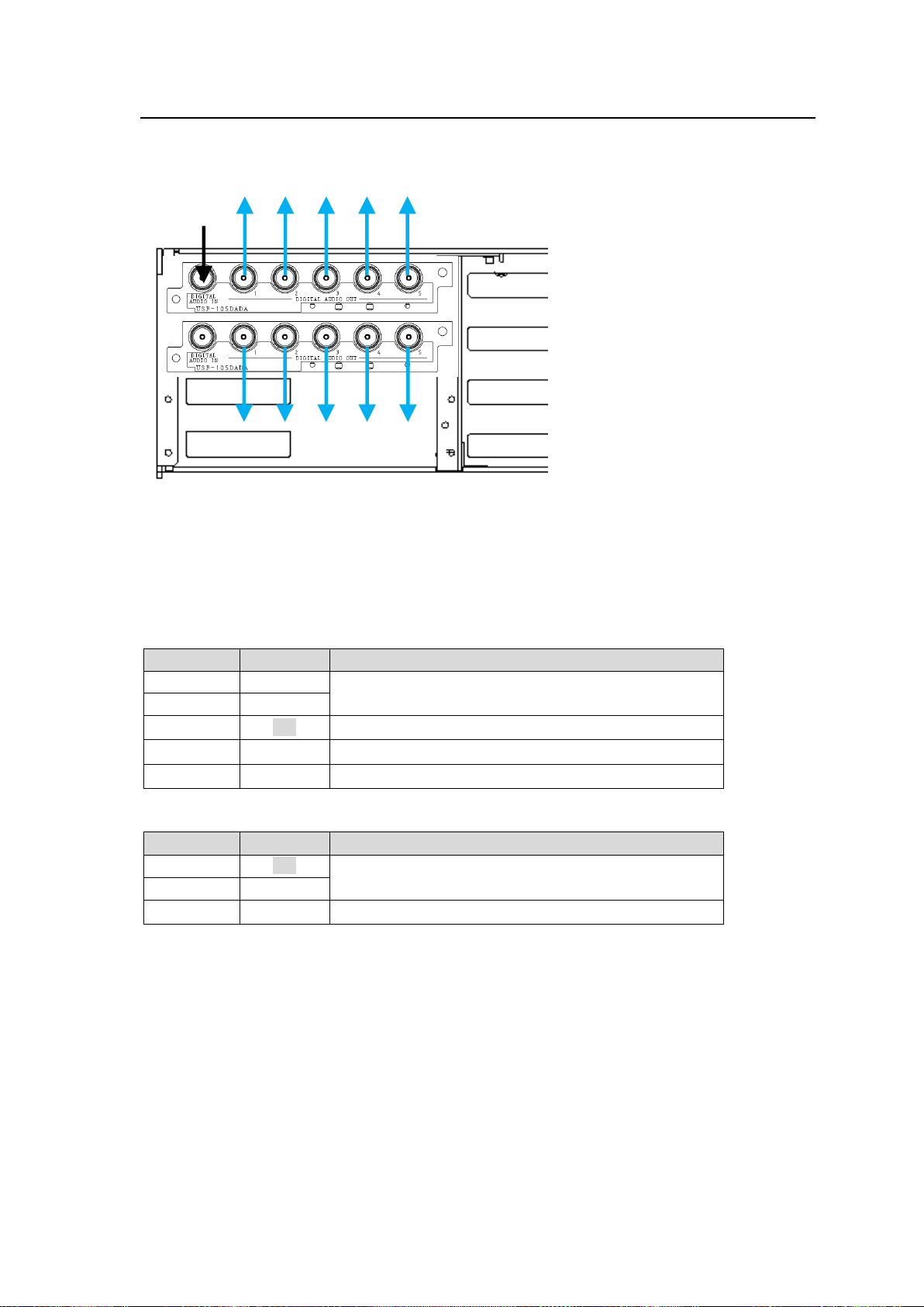
9-1. Settings to Distribute 10 Output Signals from 1 Input
Switch
Setting
Description
Switch 3
OFF
Uses input via rear panel BNC. (Default)
Switch 4
OFF
Switch 5
ON
Outputs to Slot 2 through Internal Bus1.
Switch 6
OFF
(Default)
Switch 7
OFF
(Default)
Switch
Setting
Description
Switch 3
ON
Uses input via Internal Bus 1 and distributes from Slot1
out.
Switch 4
OFF
Switch 5-7
OFF
(Default)
Input
Signal
When USF-105DADAs are installed into Slots 1 and 2 as shown below, settings to distribute 10
outputs from the Slot 1 input signal are explained in this section.
(1) Set the signal mode of USF-105DADA in Slots 1 and 2 to the same mode. (Default: AES
distribution mode) See Sec. 4 “Signal Mode Settings” for details.
(2) Set DS2 of USF-105DADAs as shown in the table below.
Slot 1 USF-105DADA - DS2 settings
Slot 2 USF-105DADA - DS2 settings
18
Page 19
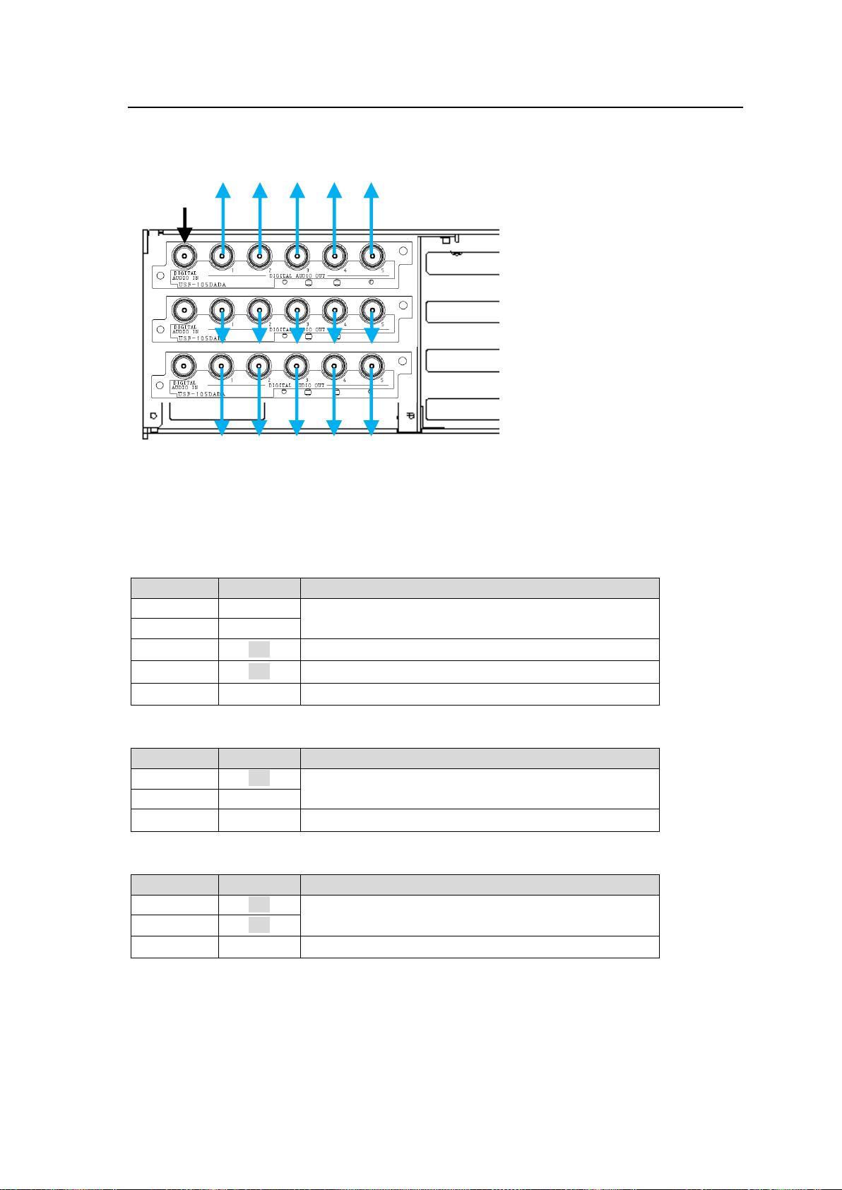
9-2. Settings to Distribute 15 Output Signals from 1 Input
Switch
Setting
Description
Switch 3
OFF
Uses input via rear panel BNC. (Default)
Switch 4
OFF
Switch 5
ON
Outputs to Slot2 through Internal Bus1.
Switch 6
ON
Outputs to Slot3 through Internal Bus2.
Switch 7
OFF
(Default)
Switch
Setting
Description
Switch 3
ON
Uses input via Internal Bus 1 and distributes output via
Slot 1.
Switch 4
OFF
Switch 5-7
OFF
(Default)
Switch
Setting
Description
Switch 3
ON
Uses input via Internal Bus 3 and distributes output via
Slot. 1.
Switch 4
ON
Switch 5-7
OFF
(Default)
Input
Signal
When USF-105DADAs are installed in Slots 1, 2 and 3 as shown below, settings to distribute 15
outputs from the Slot 1 input signal are explained in this section.
(1) Set signal mode of USF-105DADA in Slot1 - 3 as the same mode. (Default: AES distribution
mode) See Sec. 4 “Signal Mode Setting” for details.
(2) Set DS2 of USF-105DADAs as shown in the table below.
Slot 1 USF-105DADA - DS2 settings
Slot 2 USF-105DADA - DS2 settings
Slot 3 USF-105DADA - DS2 settings
19
Page 20
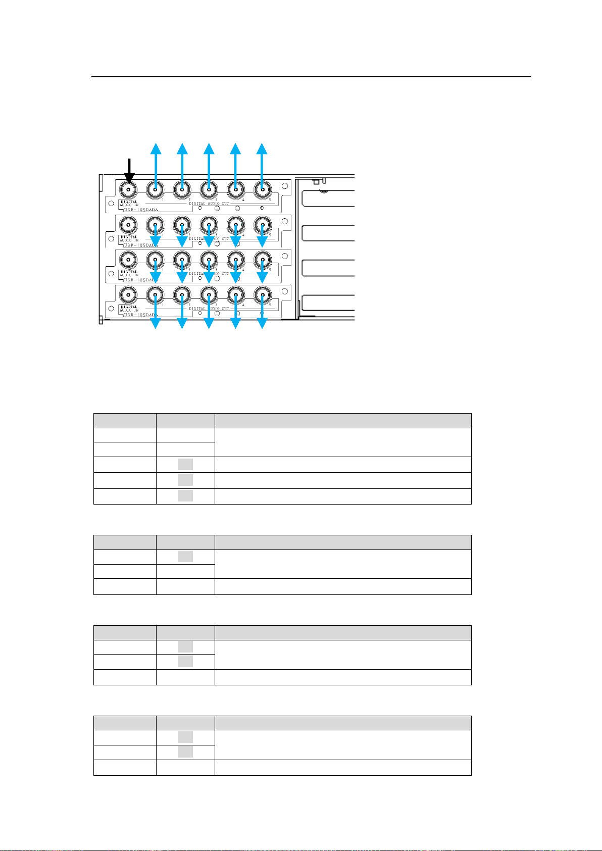
9-3. Settings to Distribute 20 Output Signals from 1 Input
Switch
Setting
Description
Switch 3
OFF
Uses input via rear panel BNC. (Default)
Switch 4
OFF
Switch 5
ON
Outputs to Slot2 through Internal Bus1.
Switch 6
ON
Outputs to Slot3 through Internal Bus2.
Switch 7
ON
Outputs to Slot4 through Internal Bus3.
Switch
Setting
Description
Switch 3
ON
Uses input via Internal Bus 1 and distributes from Slot1
out.
Switch 4
OFF
Switch 5-7
OFF
(Default)
Switch
Setting
Description
Switch 3
ON
Uses input via Internal Bus 3 and distributes from Slot1
out.
Switch 4
ON
Switch 5-7
OFF
(Default)
Switch
Setting
Description
Switch 3
ON
Uses input via Internal Bus 3 and distributes from Slot1
out.
Switch 4
ON
Switch 5-7
OFF
(Default)
Input
Signal
When USF-105DADAs are installed into Slot 1 to 4 as shown below, settings to distribute 20
outputs from the Slot 1 input signal are explained in this section.
(1) Set signal mode of USF-105DADA in Slots 1 to 4 to the same mode. (Default: AES distribution
mode) See Sec. 4 “Signal Mode Settings” for details.
(2) Set DS2 of USF-105DADAs as shown in the table below.
Slot 1 USF-105DADA - DS2 settings
Slot 2 USF-105DADA - DS2 settings
Slot 3 USF-105DADA - DS2 settings
Slot 4 USF-105DADA - DS2 settings
20
Page 21
10. Specifications and Dimensions
Input Signal
AES Distribution Mode
AES/EBU 75Ω BNC x 1 1.0Vp-p
LTC Distribution Mode
LTC 1kΩ BNC x 1 0.5 to 4.5Vp-p
Word Clock Distribution
Mode
Word Clock 1kΩ BNC x 1 2 to 5Vp-p
Output Signal
AES Distribution Mode
AES/EBU 75Ω BNC x 5 1.0V p-p within ±10%
LTC Distribution Mode
LTC 75Ω BNC x 5 2.0V p-p within ±10%
(Terminated at 75Ω)
Word Clock Distribution
Mode
Word Clock 75Ω BNC x 5 2.5Vp-p within ±10%
(Terminated at 75Ω)
Output level is adjusted to DC 0V as midpoint of amplitude in all distribution
modes. Apply minimum output load resistance 75Ω or over.
Output Gain
Adjusting
Range
AES Distribution Mode
Not adjustable
LTC Distribution Mode
Settings per output port are available.
Adjustable to about ±3dB on input signal.
Word Clock Distribution
Mode
SNMP
Via Web browser or SNMP (USF-212S frame required)
SNMP applicable version v2C
Temperature
0ºC to 40ºC
Humidity
30% to 90% (no condensation)
Power
Supplied from USF frame, +24 VDC
Power
Consumption
6.2VA (6.2W)
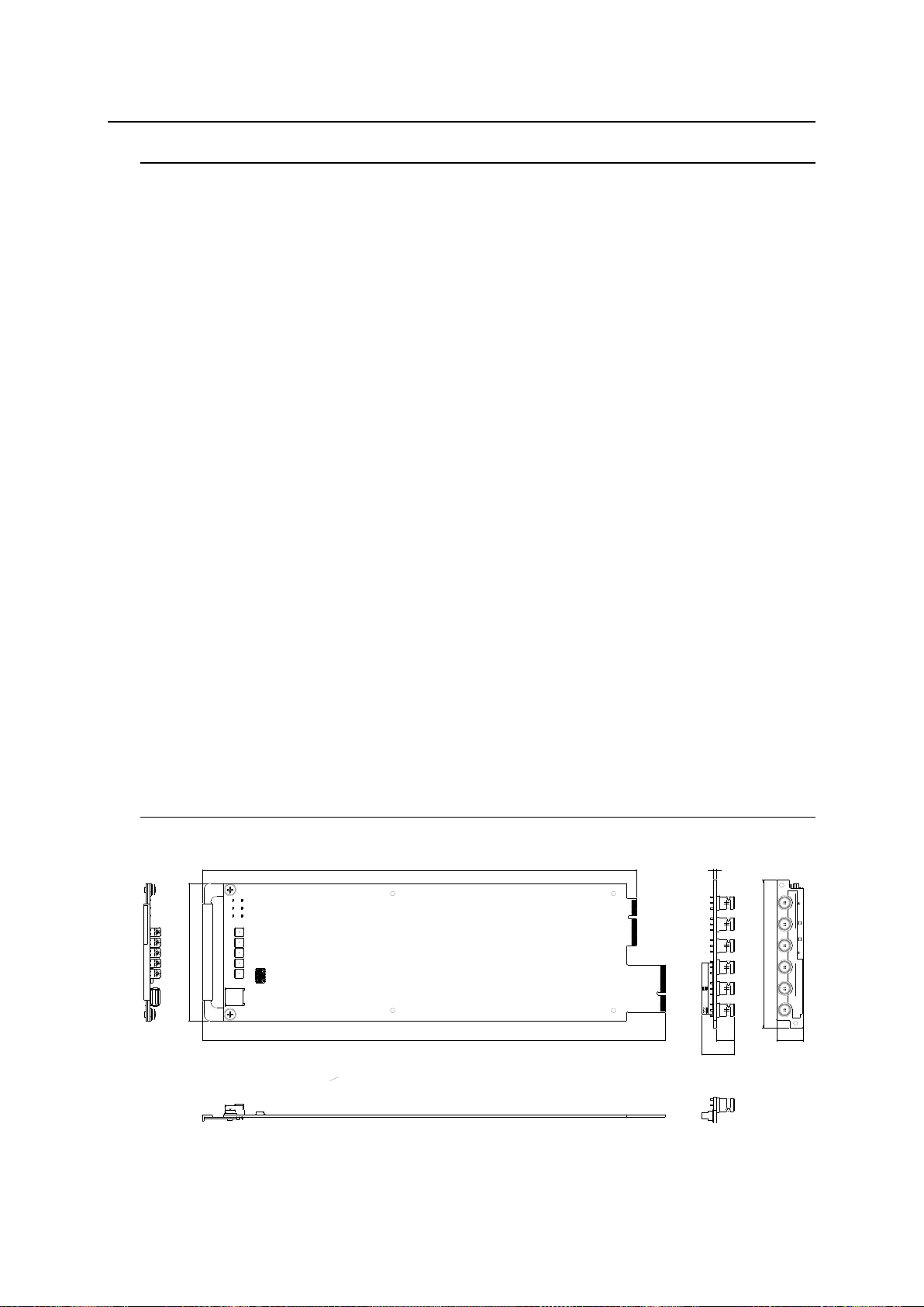
Dimensions
106 (W) x 356 (D) mm (Front card)
114(W) x 20.2 (D) mm (Rear card)
Weight
250 g
Required Slot
1
334
1
0
6
356
1
1
4
20
2.8
24.7
13.3
D
I
G
I
T
A
L
A
U
D
I
O
I
N
U
S
F
-
1
0
5
D
A
D
A
1
2
3
4
5
D
I
G
I
T
A
L
A
U
D
I
O
O
U
T
U
S
F
1
0
5
D
A
D
A
10-1. Unit Specifications
10-2. External Dimensions
21
(All dimensions in mm.)
 Loading...