

Page 1
OPERATION
MANUAL
USF-1053DDA
Digital Distribution Amplifier
2nd Edition – Rev. 3
Page 2
Precautions
Stop
Do not place or drop heavy or sharp-edged objects on the power cord. A damaged
cord can cause fire or electrical shock hazards. Regularly check the power cord for
excessive wear or damage to avoid possible fire / electrical hazards.
Stop
Do not touch any parts / circuitry with a high heat factor.
Capacitors can retain enough electric charge to cause mild to serious shock, even after
the power has been disconnected. Capacitors associated with the power supply are
especially hazardous.
Hazard
Unit should not be operated or stored with cover, panels, and / or casing removed.
Operating the unit with circuitry exposed could result in electric shock / fire hazards or
a unit malfunction.
Caution
If abnormal odors or noises are noticed coming from the unit, immediately turn the
power off and disconnect the power cord to avoid potentially hazardous conditions. If
problems similar to the above occur, contact an authorized service representative
before attempting to operate the unit again.
Caution
Consumable items that are used in the unit must be periodically replaced. For further
details on which parts are consumables and when they should be replaced, refer to the
specifications at the end of the Operation Manual. Since the service life of the
consumables varies greatly depending on the environment in which they are used,
such items should be replaced at an early date. For details on replacing consumable
items, contact your dealer.
Important Safety Warnings
[Power]
[Circuitry Access]
[Potential Hazards]
[Consumables]
2
Page 3
Upon Receipt
ITEM
QTY
REMARKS
USF-1053DDA
1 set
USF-1053DDA Front Module
USF-1053DDA Rear Module
DVD-ROM
1
Operation Manual (PDF)
Screw (for Rear Module Installation)
2
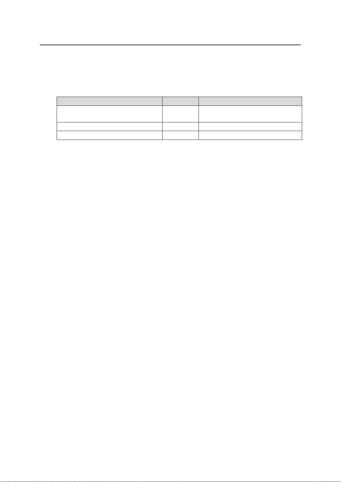
Congratulations! By purchasing a USF-1053DDA Digital Distribution Amplifier, you have entered the
world of FOR-A and its many innovative products.
Check your received items against the packing list below. Check to ensure no damage has occurred
during shipment. If damage has occurred, or items are missing, inform your supplier immediately.
USF-1053DDA
* This product can be installed into the following frames:
USF-212
USF-212S/AS
USF-105S/AS
3
Page 4

Table of Contents
1. Product Overview ................................................................................................................................. 5
1-1. Overview ..................................................................................................................................... 5
1-2. Features ...................................................................................................................................... 5
2. Panel Descriptions ................................................................................................................................ 6
2-1. Front Panel .................................................................................................................................. 6
2-2. Rear Panel .................................................................................................................................. 6
3. DIP Switch Settings .............................................................................................................................. 7
4. USF-1053DDA I/O via USF-212S/AS Internal Bus .............................................................................. 9
4-1. Distributing another USF-1053DDA module input (1 x 10) .......................................................10
4-1-1. Input Settings via DIP Switch .............................................................................................10
4-1-2. Input Settings via Web GUI ...............................................................................................10
4-2. Distributing another type module input .....................................................................................11
4-2-1. Input Settings via DIP Switch .............................................................................................11
4-2-2. Input Settings via Web GUI ...............................................................................................11
5. USF-1053DDA I/O via USF-105S/AS Internal Bus ............................................................................12
5-1. Slot 1 to Slot 2 ...........................................................................................................................12
5-1-1. Input Settings via DIP Switch .............................................................................................12
5-1-2. Input Settings via Web GUI ...............................................................................................12
5-2. Slot 2 to Slot 1 ...........................................................................................................................13
5-2-1. Input Settings via DIP Switch .............................................................................................13
5-2-2. Input Settings via Web GUI ...............................................................................................13
5-3. Slot 3 to Slot 4 ...........................................................................................................................13
5-3-1. Input Settings via DIP Switch .............................................................................................14
5-3-2. Input Settings via Web GUI ...............................................................................................14
5-4. Slot 4 to Slot 3 ...........................................................................................................................14
5-4-1. Input Settings via DIP Switch .............................................................................................14
5-4-2. Input Settings via Web GUI ...............................................................................................14
6. Web GUI .............................................................................................................................................15
6-1. Web Display Information ...........................................................................................................15
6-2. syslog Functions .......................................................................................................................17
7. About SNMP .......................................................................................................................................18
8. Specifications and Dimensions ..........................................................................................................19
8-1. Specifications ............................................................................................................................19
8-2. External Dimensions .................................................................................................................19
4
Page 5

1. Product Overview
1-1. Overview
The USF-1053DDA is a multi-bit rate video distribution amplifier that can be installed in a USF
frame. The USF-1053DDA supports 3G-SDI, HD-SDI, SD-SDI, and DVB-ASI, and is capable of
producing up to 5 outputs from 1 input.
1-2. Features
Installs into USF frames.
1 input 5 distribution outputs
Supports SDI 3Gbps,1.5Gbps, and 270Mbps. (Automatic)
3G/HD/SD-SDI equalizer and re-clock functions.
Detection of input signal and identification of 3Gbps/1.5Gbps/270Mbps is possible.
Supports DVB-ASI (270Mbps) signal.
1 input 10 distribution outputs available with two USF-1053DDA modules.
Limitation on installation methods may apply.
5
Page 6
2. Panel Descriptions
No.
Name
Description
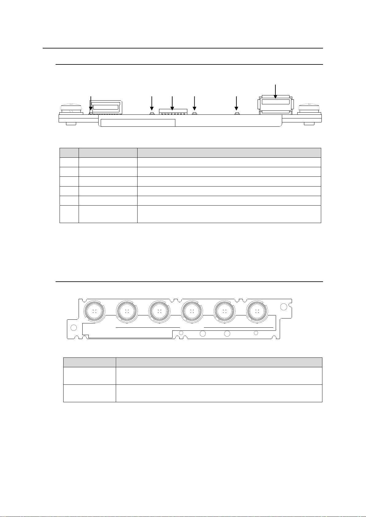
(1)
OPERATE LED
Lights green when power is supplied by USF frame.
(2)
270Mb/s LED *1
Lights green when input SDI signal is 270M b/s.
(3)
DIP Switch
Sets input signal switching.
(4)
1.5Gb/s LED *1
Lights green when input SDI signal is 1.5G b/s.
(5)
3.0Gb/s LED *1
Lights green when input SDI signal is 3G b/s.
(6)
USB connector
Used to upgrade USF-1053DDA software.
(Do not connect USB devices.)
Name
Description
SDI IN
SDI signal input.
Accepts an SD/HD/3G-SDI signal.
SDI OUT 1 - 5
SDI signal outputs.
Distributes the SDI IN input to 5 outputs.
SDI IN
1 2 3 4 5
SDI OUT
USF-1053DDA
(2)
(3)
(4)
(5)
(1)
(6)
USF-1053DDA
2-1. Front Panel
*1 When video signals routed from USF frame internal bus are distributed, video signal bit rate detection is
not available. All the LEDs; 270Mb/s, 1.5Gb/s, and 3.0Gb/s are turned off.
Refer to Sec. 4 “USF-1053DDA I/O via USF-212S/AS Internal Bus” for switching the video
signal source.
2-2. Rear Panel
6
Page 7
3. DIP Switch Settings
SW
No.
Function
Setting
Factory Setting*1
OFF
ON
1
Input Signal
Switching
Input
Signal
Switching
(See
Table1)
Input
Signal
Switching
(See
Table1)
When installed in USF-212: ON (Recommended)
When installed in USF-212S/AS: OFF (Recommended)
When only USF-1053DDA is shipped: OFF
2
OFF
3
OFF
4
OFF
5
(Factory use)
-
-
ON
6
(Factory use)
-
-
OFF
7
(Factory use)
-
-
OFF
8
(Factory use)
-
-
OFF
IMPORTANT
SW Nos. 5 to 8 are factory use only. Do not change these settings.
Slot
SW1
SW2
SW3
SW4
Input signal for distribution
-
OFF
OFF
OFF
OFF
Set by Web GUI.
1
ON
OFF
OFF
OFF
Distributes Slot 1 input. (Rear input)
OFF
ON
OFF
OFF
Distributes Slot 2 input. (Via frame internal bus)
OFF
OFF
ON
OFF
Distributes Slot 3 input. (Via frame internal bus)
OFF
OFF
OFF
ON
Distributes Slot 4 input. (Via frame internal bus)
2
ON
OFF
OFF
OFF
Distributes Slot 2 input. (Rear input).
OFF
ON
OFF
OFF
Distributes Slot 1 input. (Via frame internal bus).
OFF
OFF
ON
OFF
Distributes Slot 3 input. (Via frame internal bus)
OFF
OFF
OFF
ON
Distributes Slot 4 input. (Via frame internal bus)
3
ON
OFF
OFF
OFF
Distributes Slot 3 input. (Rear input)
OFF
ON
OFF
OFF
Distributes Slot 1 input. (Via frame internal bus)
OFF
OFF
ON
OFF
Distributes Slot 2 input. (Via frame internal bus).
OFF
OFF
OFF
ON
Distributes Slot 4 input. (Via frame internal bus)
4
ON
OFF
OFF
OFF
Distributes Slot 4 input. (Rear input)
OFF
ON
OFF
OFF
Distributes Slot 1 input. (Via frame internal bus).
OFF
OFF
ON
OFF
Distributes Slot 2 input. (Via frame internal bus)
OFF
OFF
OFF
ON
Distributes Slot 3 input. (Via frame internal bus).
5
ON
OFF
OFF
OFF
Distributes Slot 5 input. (Rear input).
OFF
ON
OFF
OFF
Distributes Slot 6 input. (Via frame internal bus)
OFF
OFF
ON
OFF
Distributes Slot 7 input. (Via frame internal bus)
OFF
OFF
OFF
ON
Distributes Slot 8 input. (Via frame internal bus)
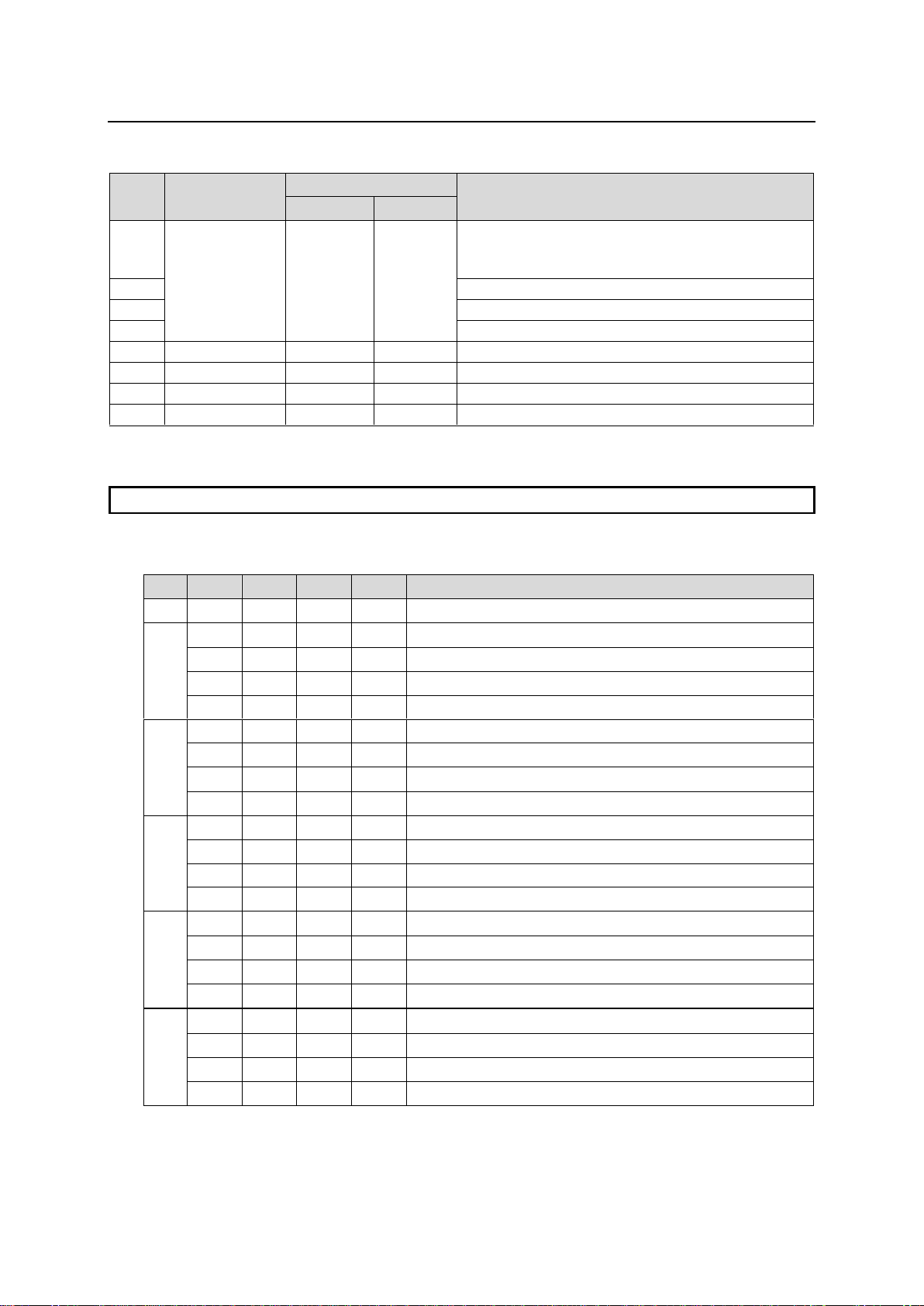
The front DIP switch settings allow you to set input signal switching, re-clock function settings, etc.
*1 The switch is set suitable for the main unit when shipped out from our factory.
Table 1: Input Signal Switch Settings
Slot: USF frame slot no. into which USF-1053DDA is installed.
7
Page 8
Slot
SW1
SW2
SW3
SW4
Output Signal
6
ON
OFF
OFF
OFF
Distributes Slot 6 input. (Rear input)
OFF
ON
OFF
OFF
Distributes Slot 5 input. (Via frame internal bus)
OFF
OFF
ON
OFF
Distributes Slot 7 input. (Via frame internal bus)
OFF
OFF
OFF
ON
Distributes Slot 8 input. (Via frame internal bus)
7
ON
OFF
OFF
OFF
Distributes Slot 7 input. (Rear input)
OFF
ON
OFF
OFF
Distributes Slot 5 input. (Via frame internal bus)
OFF
OFF
ON
OFF
Distributes Slot 6 input. (Via frame internal bus)
OFF
OFF
OFF
ON
Distributes Slot 8 input. (Via frame internal bus).
8
ON
OFF
OFF
OFF
Distributes Slot 8 input. (Rear input)
OFF
ON
OFF
OFF
Distributes Slot 5 input. (Via frame internal bus).
OFF
OFF
ON
OFF
Distributes Slot 6 input. (Via frame internal bus)
OFF
OFF
OFF
ON
Distributes Slot 7 input. (Via frame internal bus).
9
ON
OFF
OFF
OFF
Distributes Slot 9 input. (Rear input)
OFF
ON
OFF
OFF
Distributes Slot 10 input. (Via frame internal bus)
OFF
OFF
ON
OFF
Distributes Slot 11 input. (Via frame internal bus).
OFF
OFF
OFF
ON
Distributes Slot 12 input. (Via frame internal bus).
10
ON
OFF
OFF
OFF
Distributes Slot 10 input. (Rear input)
OFF
ON
OFF
OFF
Distributes Slot 9 input. (Via frame internal bus).
OFF
OFF
ON
OFF
Distributes Slot 11 input. (Via frame internal bus).
OFF
OFF
OFF
ON
Distributes Slot 12 input. (Via frame internal bus)
11
ON
OFF
OFF
OFF
Distributes Slot 11 input. (Rear input)
OFF
ON
OFF
OFF
Distributes Slot 9 input. (Via frame internal bus)
OFF
OFF
ON
OFF
Distributes Slot 10 input. (Via frame internal bus).
OFF
OFF
OFF
ON
Distributes Slot 12 input. (Via frame internal bus)
12
ON
OFF
OFF
OFF
Distributes Slot 12 input. (Rear input).
OFF
ON
OFF
OFF
Distributes Slot 9 input. (Via frame internal bus)
OFF
OFF
ON
OFF
Distributes Slot 10 input. (Via frame internal bus)
OFF
OFF
OFF
ON
Distributes Slot 11 input. (Via frame internal bus)
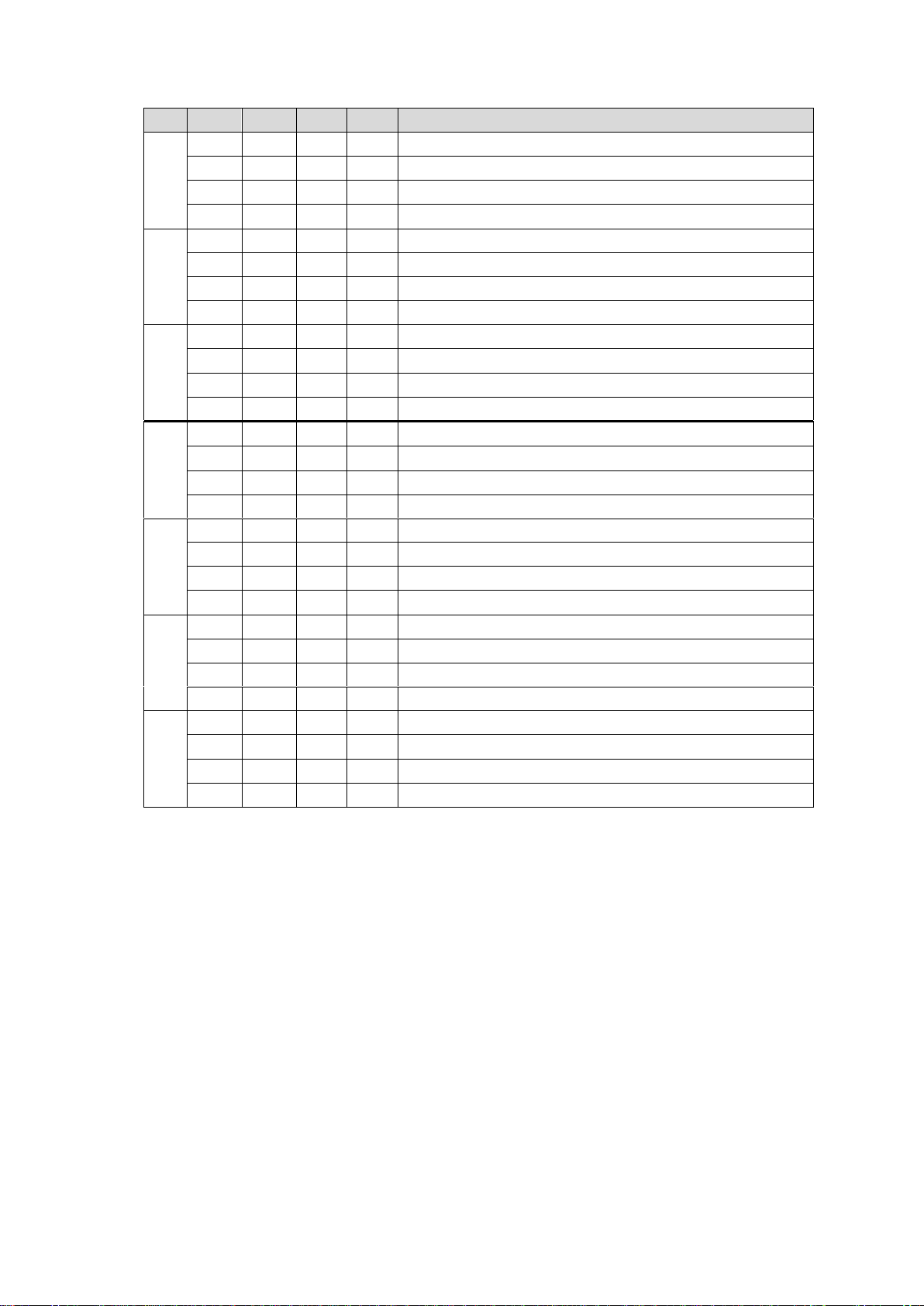
In case SW1 to SW4 are set to other than those described in Table 1: Input Signal
Switching Settings, USF-1053DDA will distribute its input.
8
Page 9
4. USF-1053DDA I/O via USF-212S/AS Internal Bus
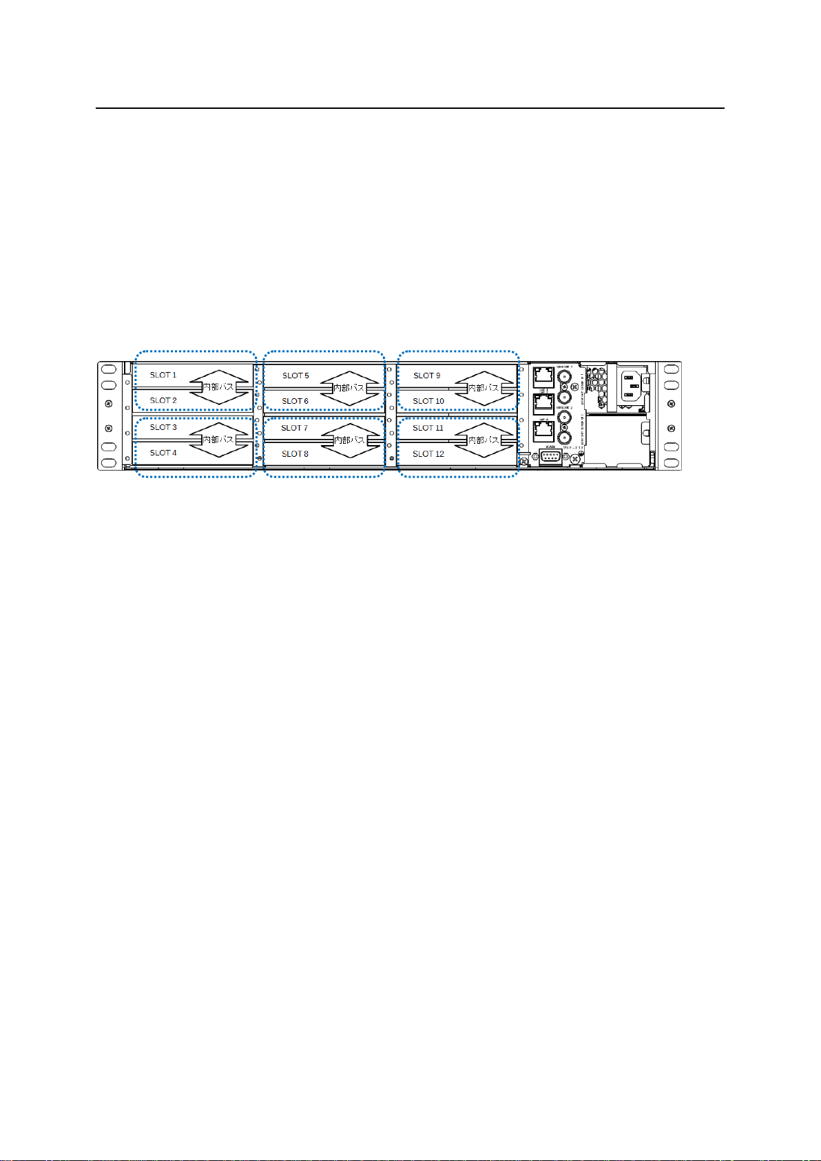
USF-1053DDA modules can input an SDI signal via USF-212S/AS frame internal bus.
USF-1053DDA modules can output an SDI signal via USF-212S/AS frame internal bus.
To use frame internal buses for video signal distribution, change module settings using dip switches on
USF-1053DDA front panels or Web GUI pages.
Distributing another USF-1053DDA module input (1 x 10)
The number of outputs can be increased up to 10 by installing two USF-1053DDA modules into a USF
frame and using internal bus lines. Install module pairs according to the figure shown above (e.g., into
Slot 1 and Slot 2.). (See Sec. 4-1. “Distributing another USF-1053DDA module input (1 x 10).”)
USF-212S/AS Frame Rear Panel
Distributing another type module input
A USF-1053DDA module can be paired with another type of USF module, for instance a USF-1043FS.
In such cases these two modules should be installed in any slots, from Slots 1 to 4. The same applies
for Slots 5 to 8 and Slots 9 to 12. (Refer to Sec. 4-2. “Distributing another type module input.”)
9
Page 10
4-1. Distributing another USF-1053DDA module input (1 x 10)
USF-1053DDA
SW1
SW2
SW3
SW4
Uses the rear panel input.
Slot 1
ON
OFF
OFF
OFF
USF-1053DDA
SW1
SW2
SW3
SW4
Uses the Slot 1 input.
Slot 2
OFF
ON
OFF
OFF
3G/HD/SD SDI IN
USF-1043FS
1 2
1 2 3 4
3G/HD/SD SDI OUT
SDI IN
1 2 3 4 5
SDI OUT
USF-1053DDA
Slot 1
(USF-1053DDA)
Slot 2
(USF-1053DDA)
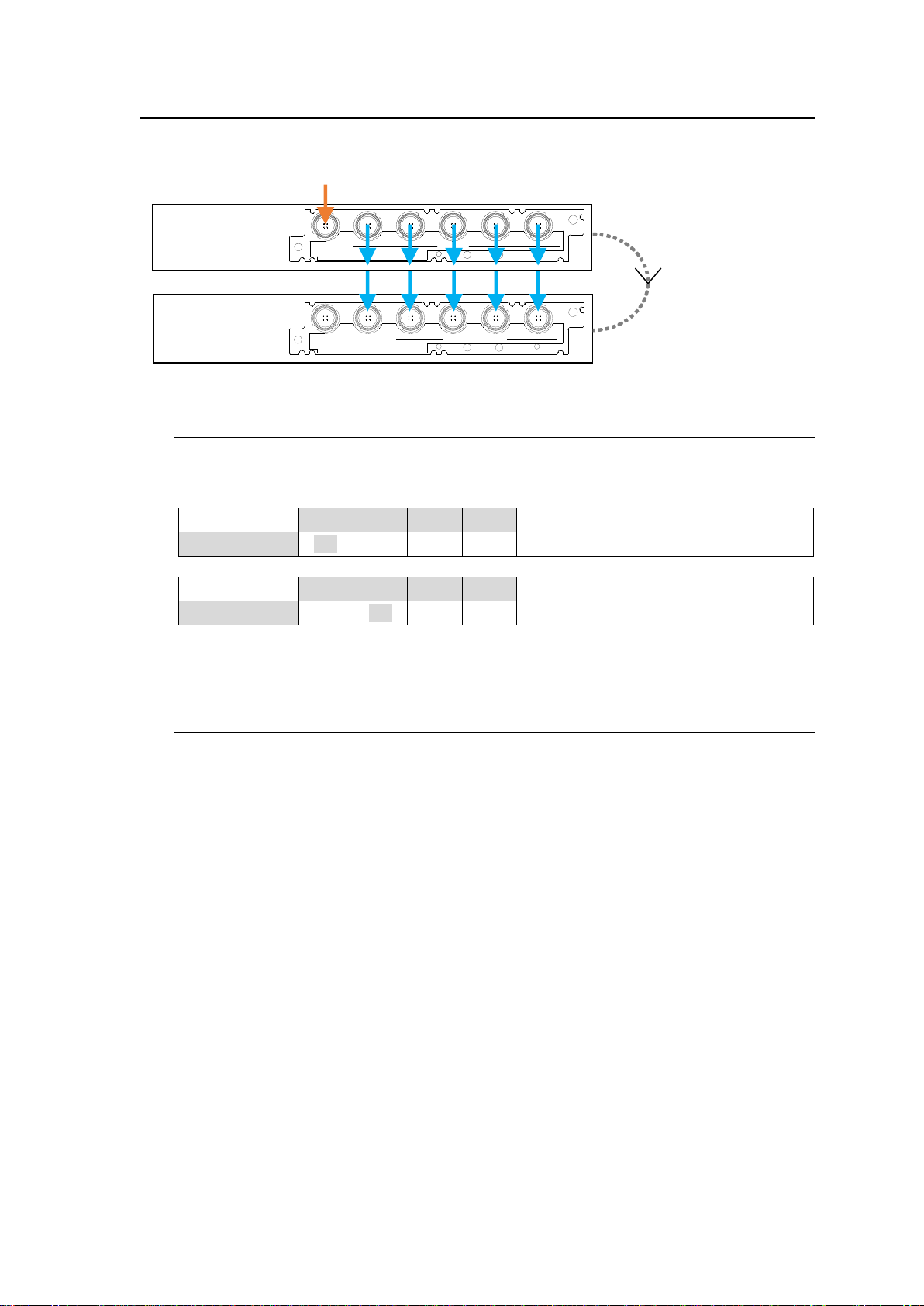
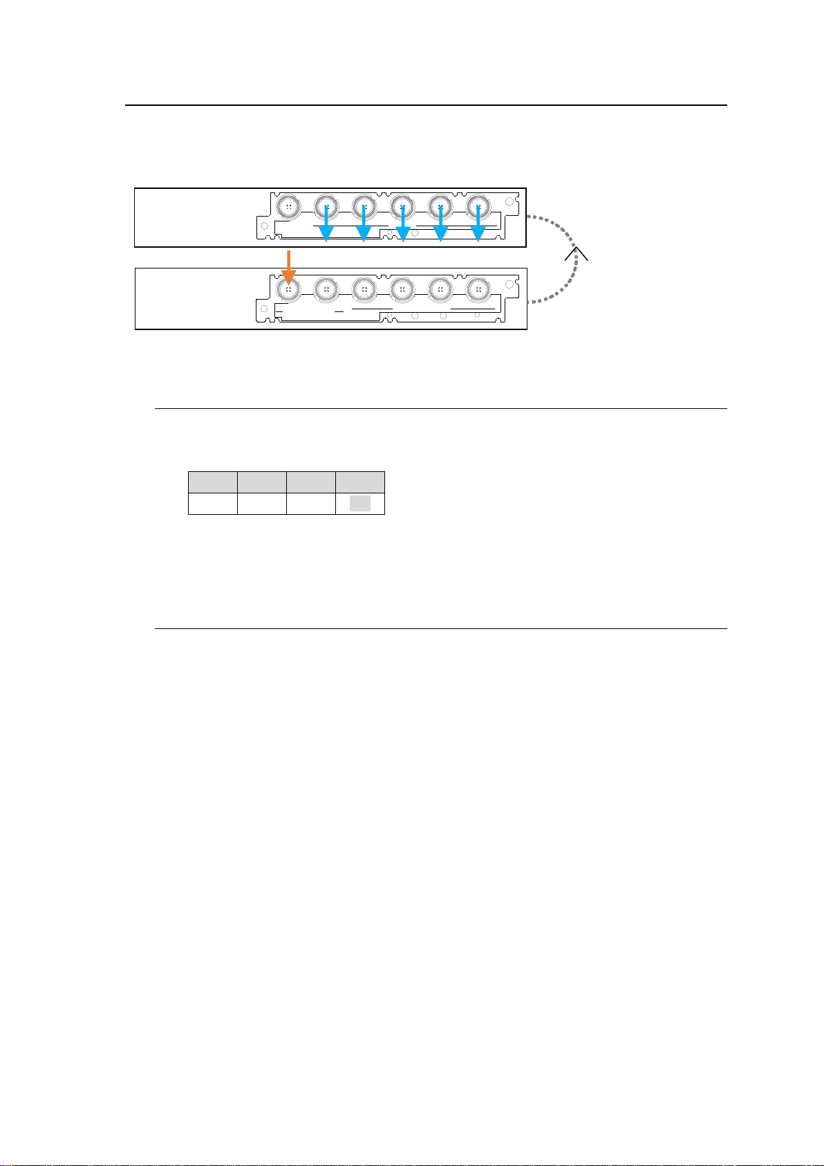
This section describes an example of how to distribute the Slot 1 input to 10 outputs when two
USF-1053DDA modules are installed into Slots 1 and 2.
4-1-1. Input Settings via DIP Switch
Set the front panel DIP switches on USF-1053DDA modules to those shown in the tables
below and install them into Slot 1 and Slot 2 on the USF frame.
See Sec. 3. “DIP Switch Settings” for other USF-1053 module pair settings.
4-1-2. Input Settings via Web GUI
(1) Install two USF-1053DDA modules into Slots 1 and 2.
(2) Start the Web GUI and set as follows.
Set Slot 1 Input Source to Rear In.
Set Slot 2 Input Source to Slot 1.
(3) Input a video signal into SDI IN of the USF-1053DDA in Slot 1.
10
Page 11
4-2. Distributing another type module input
SW1
SW2
SW3
SW4
OFF
OFF
OFF
ON
3G/HD/SD SDI IN
USF-1043FS
1 2
1 2 3 4
3G/HD/SD SDI OUT
SDI IN
1 2 3 4 5
SDI OUT
USF-1053DDA
Slot 1
(USF-1053DDA)
Slot 4
(USF-1043FS)
This section describes an example of how to route the Slot 4 input to Slot 1 output when
USF-1053DDA is installed in Slot 1 and USF-1043FS is installed in Slot 4.
4-2-1. Input Settings via DIP Switch
(1) Set USF-1053DDA DIP switch settings to those shown in the table below and install the
module into Slot 1 on the USF Frame.
(2) Install a USF-1043FS into Slot 4 of the USF frame.
(3) Input a video signal into SDI IN1 of the USF-1043FS in Slot 4.
4-2-2. Input Settings via Web GUI
(1) Install a USF-1053DDA into Slot 1 and USF-1043FS into Slot 4.
(2) Start the Web GUI and set as follows.
<USF-1053DDA>
Set Slot 4 as the Slot 1 Input Source.
<USF-1043FS>
Go to VIDEO Tab > [Video System] > [System Settings] and set Primary Source as SDI 1.
(3) Input a video signal into SDI IN1 of the USF-1043FS in Slot 4.
11
Page 12
5. USF-1053DDA I/O via USF-105S/AS Internal Bus
A
L
A
R
M
12
AC100-240V 50/60Hz IN
L
A
N
1
L
A
N
A
GENLOCK
USF-1053DDA
SW1
SW2
SW3
SW4
Uses the rear panel input.
Slot 1
ON
OFF
OFF
OFF
USF-1053DDA
SW1
SW2
SW3
SW4
Uses the Slot 1 input.
Slot 2
OFF
ON
OFF
OFF
3G/HD/SD SDI IN
USF-1043FS
1 2
1 2 3 4
3G/HD/SD SDI OUT
SDI IN
1 2 3 4 5
SDI OUT
USF-1053DDA
SLOT 1
(USF-1053DDA)
SLOT 2
(USF-1053DDA)
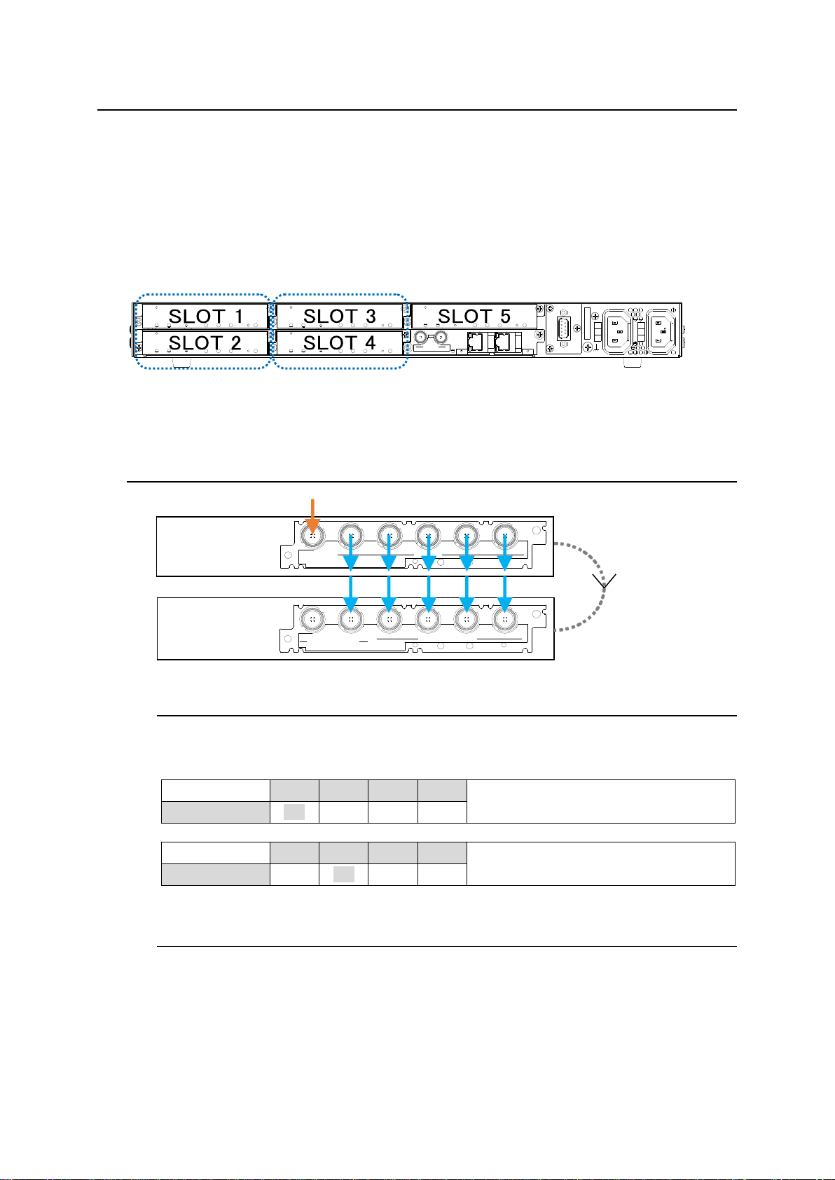
USF-1053DDA modules can input an SDI signal via USF-105S/AS frame internal bus.
USF-1053DDA modules can output an SDI signal via USF-105S/AS frame internal bus.
The number of outputs can be increased up to 10 by installing two USF-1053DDA modules into a USF
frame and using internal bus lines. Install a module pair into Slot 1 and Slot 2 or Slot 3 and Slot 4 on
the USF-105S/AS frame
USF-105S/AS Frame Rear Panel
To use frame internal buses for video signal distribution, change module settings using dip switches on
the USF-1053DDA front panel or in the Web GUI page.
5-1. Slot 1 to Slot 2
5-1-1. Input Settings via DIP Switch
Set the front panel DIP switches on USF-1053DDA modules to those shown in the tables
below and install them into Slot 1 and Slot 2 on the USF frame.
5-1-2. Input Settings via Web GUI
(1) Install two USF-1053DDA modules into Slots 1 and 2.
(2) Start the 1053DDA Web GUI and set as follows.
Set Slot 1 Input Source to Rear In.
Set Slot 2 Input Source to Slot 1.
12
Page 13
5-2. Slot 2 to Slot 1
USF-1053DDA
SW1
SW2
SW3
SW4
Uses the Slot 2 input.
Slot 1
OFF
ON
OFF
OFF
USF-1053DDA
SW1
SW2
SW3
SW4
Uses the rear panel input.
Slot 2
ON
OFF
OFF
OFF
3G/HD/SD SDI IN
USF-1043FS
1 2
1 2 3 4
3G/HD/SD SDI OUT
SDI IN
1 2 3 4 5
SDI OUT
USF-1053DDA
Slot 3
(USF-1053DDA)
Slot 4
(USF-1053DDA)
3G/HD/SD SDI IN
USF-1043FS
1 2
1 2 3 4
3G/HD/SD SDI OUT
SDI IN
1 2 3 4 5
SDI OUT
USF-1053DDA
Slot 1
(USF-1053DDA)
Slot 2
(USF-1053DDA)
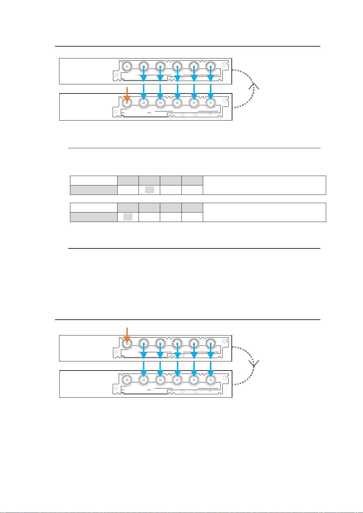
5-2-1. Input Settings via DIP Switch
Set the DIP switch settings to those shown in the tables below for two USF-1053DDA modules
and install them into Slot 1 and Slot 2 on the USF frame.
5-2-2. Input Settings via Web GUI
(1) Install two USF-1053DDA modules into Slots 1 and 2.
(2) Start the 1053DDA Web GUI and set as follows.
Set Slot 1 Input Source to Slot 2.
Set Slot 2 Input Source to Rear In.
5-3. Slot 3 to Slot 4
13
Page 14
USF-1053DDA
SW1
SW2
SW3
SW4
Uses the rear panel input.
Slot 3
ON
OFF
OFF
OFF
USF-1053DDA
SW1
SW2
SW3
SW4
Uses the Slot 3 input.
Slot 4
OFF
OFF
OFF
ON
USF-1053DDA
SW1
SW2
SW3
SW4
Uses the Slot 4 input.
Slot 3
OFF
OFF
OFF
ON
USF-1053DDA
SW1
SW2
SW3
SW4
Uses the rear panel input.
Slot 4
ON
OFF
OFF
OFF
3G/HD/SD SDI IN
USF-1043FS
1 2
1 2 3 4
3G/HD/SD SDI OUT
SDI IN
1 2 3 4 5
SDI OUT
USF-1053DDA
Slot 3
(USF-1053DDA)
Slot 4
(USF-1053DDA)
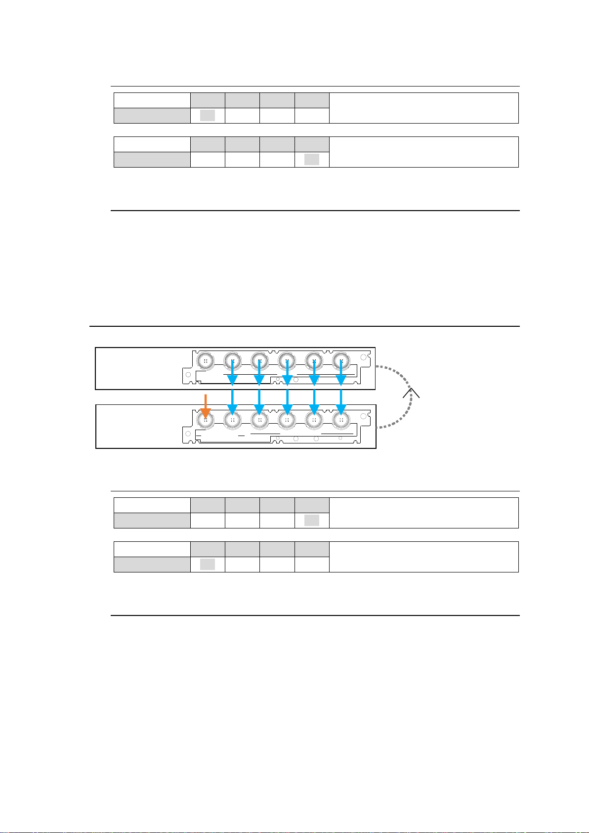
5-3-1. Input Settings via DIP Switch
5-3-2. Input Settings via Web GUI
(1) Install two USF-1053DDA modules into Slots 3 and 4.
(2) Start the 1053DDA Web GUI and set as follows.
Set Slot 3 Input Source to Rear In.
Set Slot 4 Input Source to Slot 3.
5-4. Slot 4 to Slot 3
5-4-1. Input Settings via DIP Switch
5-4-2. Input Settings via Web GUI
(1) Install two USF-1053DDA modules into Slots 3 and 4.
(2) Start the 1053DDA Web GUI and set as follows.
Set Slot 3 Input Source to Slot 4.
Set Slot 4 Input Source to Rear In.
14
Page 15
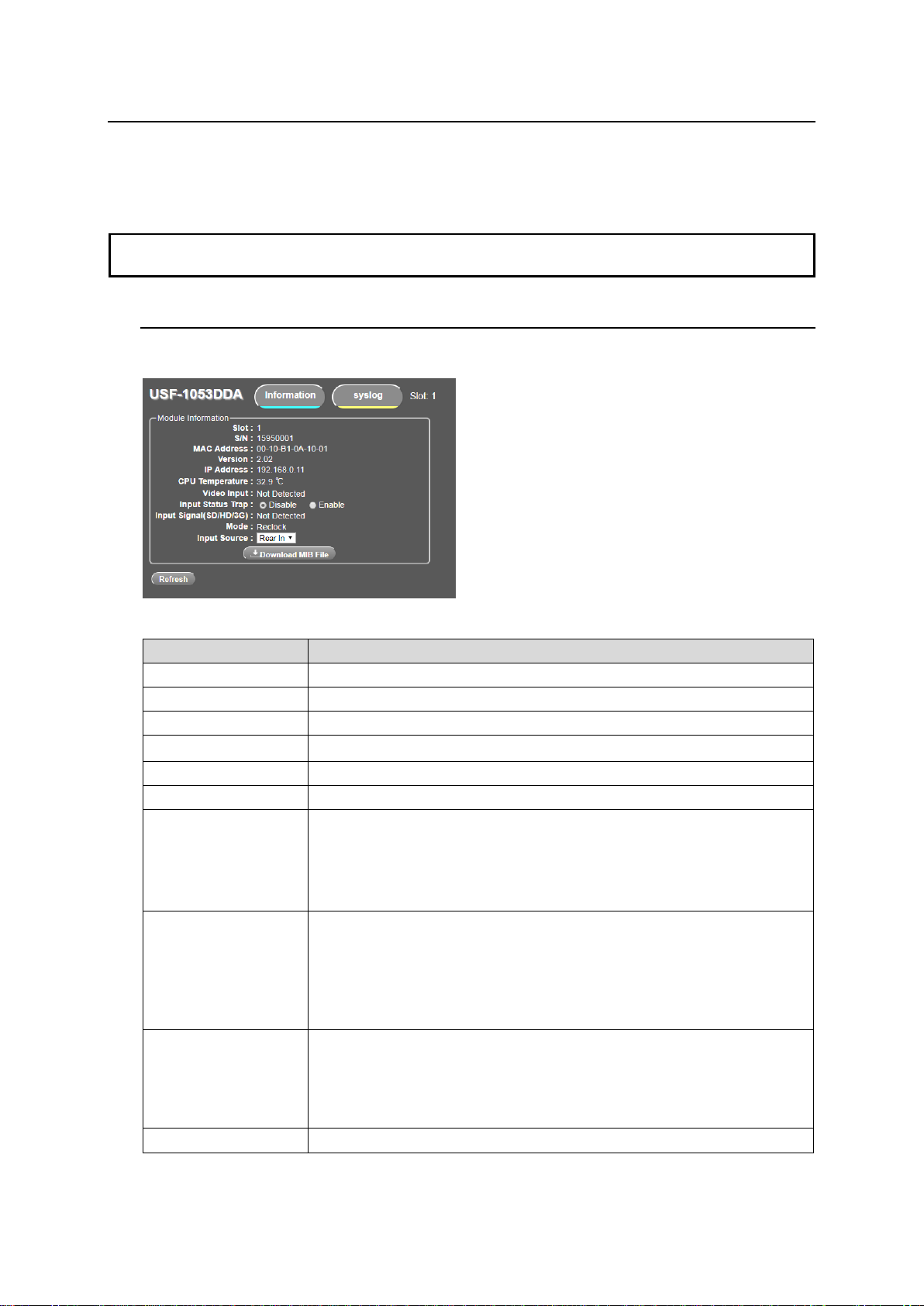
6. Web GUI
NOTE
USF-1053DDA does not support simultaneous Web GUI access from multiple PCs. To
simultaneously monitor a USF-1053DDA from multiple PCs, use the SNMP function.
Item
Description
Slot
Slot no. of the USF frame in which USF-1053DDA is installed.
S/N
Serial Number of USF-1053DDA.
MAC Address
MAC address of USF-1053DDA.
Version
Software version of USF-1053DDA.
IP Address
IP address of USF-1053DDA.
CPU Temperature
Temperature of the CPU on the USF-1053DDA.
Video Input
Displays video input status.
Detected: Normal video input.
Not Detected: No video input, or input level is low.
When Input Source is set other than Rear In, input signal cannot be
detected. “------“ is displayed.
Input Status Trap
Sets the SNMP trap setting when monitoring USF-1053DDA via SNMP
manger;
Enable: Sends input status traps
Disable: Sends no traps.
When Input Source is set other than Rear In, input signal cannot be
detected so no trap is sent although Enable is selected.
Input Signal
(SD/HD/3G)
Displays the bit rate of SDI input;
SD (270Mbit/sec), HD (1.5Gbit/sec) or 3G (3.0Gbit/sec).
No Signal: No input signal.
When Input Source is set other than Rear In, input signal bit rate cannot
be detected. “------“ is displayed.
Mode
Displays the re-clock function mode.
Status parameters of USF-1053DDA can be displayed on the Web display if the module is installed in a
USF frame. SNMP monitoring is also available. Refer to the USF frame operation manual for details on
displaying the Web GUI window.
6-1. Web Display Information
Start the Web GUI and click on a USF-1053DDA from the installed slot number to open the window
as shown below.
Module Information
15
Page 16
Input Source
Displays the USF-1053DDA Input Source.
Rear In or Slot 1 to 12
Input Sources are settable via Web GUI if SW1 to SW4 are all Off.
The slot number(s) set by “Table 1: Input Signal Switch Settings” are
shown grayed out here if any of SW1 to SW4 switch(es) is(are) On,
Downloading MIB Files
(1) Click to download the MIB (Management Information Base) for your SNMP
manager.
(2) Select Save (S) from the opened dialog box.
(3) FORA-USF1053DDA-MIB.zip File is downloaded.
(4) Unzip the file and load it into your SNMP manager.
16
Page 17
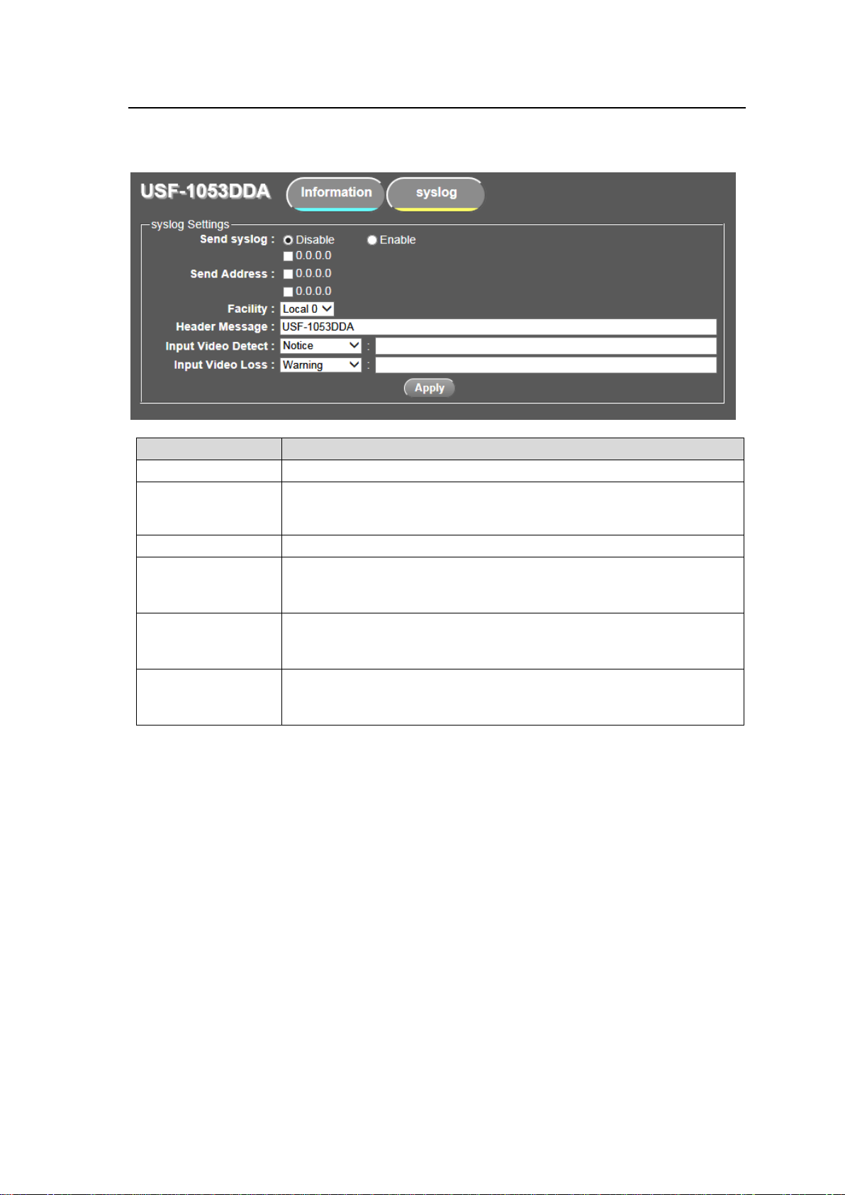
6-2. syslog Functions
Item
Descriptions
Send syslog
Select Enable to send syslog messages to the management terminal.
Send address
Sets the IP address to send syslog messages to. The IP address is the
same as the SNMP trap address. Refer to the USF frame operation
manual for details on setting SNMP trap addresses.
Facility
Sets syslog logging facilities in Local 0 through Local 7.
Header message
Sets syslog header messages up to a maximum of 63 alphanumeric
characters.
Factory setting: USF-1053DDA.
Input video detect
Sets detection messages for video input into USF-1053DDA (maximum
of 63 alphanumeric characters). Sets priority in 9 steps.
Factory setting: Notice.
Input video loss
Sets detection messages for input video into USF-1053DDA is lost
(maximum 63 alphanumeric characters). Sets priority in 9 steps.
Factory setting: Warning.
The USF-1053DDA supports log monitoring and message transmission via syslog protocol.
Clicking the syslog tab opens a window shown as below.
* Click Apply when settings are changed.
* When video signals routed from USF frame internal bus are distributed, , syslog messages are
not sent out.
17
Page 18
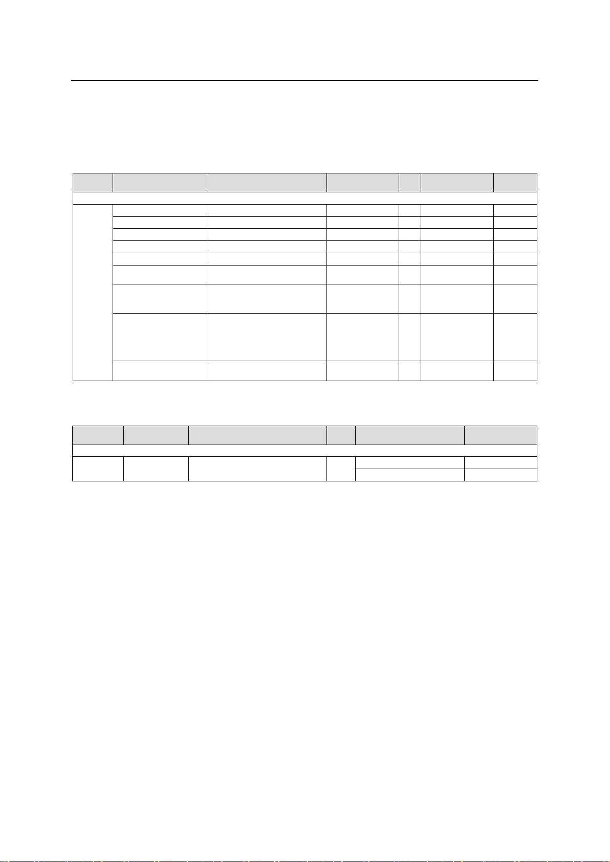
7. About SNMP
Object
group
Item Name
Object name in MIB file
Value
OID
Type
TRAP
Function
OID: 1.3.6.1.4.1.20175.1.312.1.
Unit
Status
Product Name
usf1053DdaProductName
USF-1053DDA
1
OCTET STRING
Product Code
usf1053DdaProductCode
1023808
2
INTEGER
Serial Number
usf1053DdaSerialNumber
1595****
3
INTEGER
Soft Version
usf1053DdaVersion
**.** 4 OCTET STRING
Slot Number
usf1053DdaSlotNumber
1~12
5
INTEGER
CPU Temperature
usf1053DdaCpuTemperature
** degree
Celsius
6
INTEGER
Input Video Status
usf1053DdaInputStatus
-1:cannotDetect
0: not Detected
1: detected
7
INTEGER
Input SDI Bit Rate
usf1053DdaSdiRate
-1:cannotDetect
0: not Detected
1: sdi SD
2: sdi HD
3: sdi 3G
8
INTEGER
Reclock Bypass
Setting
usf1053DdaReclockBypass
0:reclocking
1:reclock Bypass
9
INTEGER
Object
Group
Item Name
Object name in MIB file
OID
Reference Object
Type
OID: 1.3.6.1.4.1.20175.1.312.0.
TRAP
SDI Input
usf1053DdaInputStatusChanged
1
usf1053DdaSlotNumber
INTEGER
usf1053DdaInputStatus
INTEGER
The USF-1053DDA can be remotely monitored using an external SNMP monitoring system that
supports SNMPv2C. MIB (Management Information Base) files that are required for SNMP monitoring
systems can be downloaded from the Web GUI. Refer to the prior section for details on downloading
MIB files. Refer to the USF frame operation manual for details on SNMP settings.
GET List
* No item can be set from SNMP.
TRAP List
* When video signals routed from USF frame internal bus are distributed, SDI Input trap is not sent out.
18
Page 19
8. Specifications and Dimensions
Video Input
3G-SDI: 3Gbps
HD-SDI: 1.5Gbps
SD-SDI: 270Mbps
DVB-ASI: 270Mbps
75Ω BNC x 1
Video Output
3G-SDI: 3Gbps
HD-SDI: 1.5Gbps
SD-SDI: 270Mbps
DVB-ASI: 270Mbps
75Ω BNC x 5
Cable Compensation
Automatic Cable Compensation
3G-SDI: Max. 70m (Using 5C-FB-equivalent cable)
HD-SDI: Max.100m (Using 5C-FB-equivalent cable)
SD-SDI: Max. 200m (Using 5C-2V-equivalent cable)
SNMP
SNMP Monitoring available (via USF frame)
SNMP version v2C
Temperature
0ºC to 40 ºC
Humidity
30% to 90% (no condensation)
Power
+12V DC (Supplied by USF frame)
Power Consumption
3VA (3W)
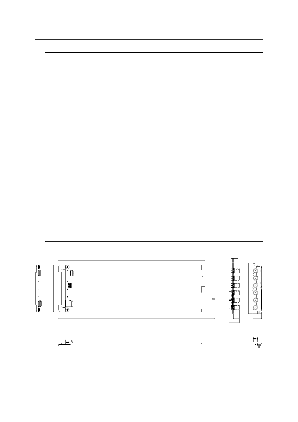
Dimensions
Front Module: 106 (W) x 356 (D) mm
Rear Module: 114 (W) x 20.2 (H) mm
Weight
220 g
Required Slot
1 Slot
1.6
1
0
6
334
356 13.5
23.6
1
1
4
U
S
F
-
1
0
5
3
D
D
A
S
D
I
I
N
1
2
3
4
5
S
D
I
O
U
T
U
S
F
-
1
0
5
3
D
D
A
20.2
8-1. Specifications
8-2. External Dimensions
(All dimensions in mm)
19
 Loading...